Embed Size (px)
Citation preview
Corrosion Control using Cathodic Protection for
Prefabricated Buried Steel Pump Stations1
Jeff Schramuk – NACE CP Specialist #7695, CP Solutions, Inc.
Abstract
Municipal water and sewer utilities can face significant economic and safety consequences
from external corrosion of buried prefabricated steel pump stations. Avoiding corrosion failure
is paramount since these structures contain sophisticated electronic controls or protect
important access points for future pump maintenance. The author’s empirical field data
shows that cathodic protection (CP) systems using sacrificial anodes on pump stations rarely
have a service life that exceeds five to seven years. Since sacrificial anode CP systems have
been shown to have a limited service life, a municipal utility that wants long-term corrosion
protection should consider a properly-designed, installed, and maintained rectified-anode CP
system. A recent study by the U.S. Federal Highway Administration and NACE International
concluded that external corrosion of buried utility structures can be effectively mitigated by
the application of coatings and cathodic protection (1).
Introduction
For the discussion that follows, a prefabricated buried steel pump station (pump station)
could be one of two types:
A water booster pump enclosure that has its pumps located at a relatively shallow depth
of approximately 10 to 15 feet below grade. Typical shapes are circular for single pump
units and oval for multi-pump installations. A single incoming water pipe enters the pump
station, runs through one or more booster pumps, and a single pipeline runs out of the
pump chamber into a water main.
Dry-pit flooded-suction sewage pump stations have ejector pumps that can be located as
much as 30 to 35 feet below grade. Typically shaped as a vertical cylinder set alongside a
cast-in-place sewage wet well. Multiple suction pipes run from the wet well into the pump
chamber. A single ejector line runs out of the pump chamber into a sewage main.
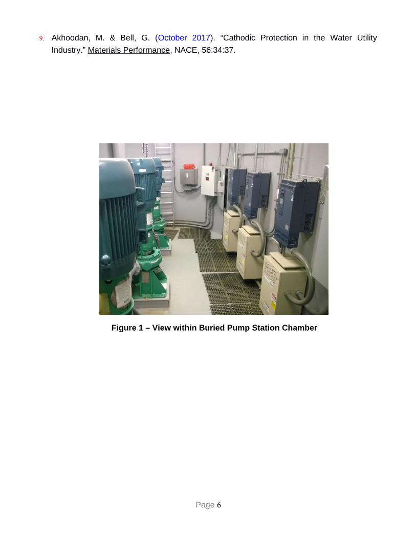
Regardless of the fluid being pumped (potable water or sewage), a pump station as shown in
Figure 1 relies on a carbon steel pump chamber to house the pumps and contain their
associated piping in a safe and controlled environment. Dehumidification, sump drains, and
air-circulation blowers work to reduce accumulated moisture within the pump station.
1� Copyright (2018): Reproducton of this informaton, in whole or in part, in any manner, without the prior writenconsent of CP Solutons, Inc., is a violaton of copyright law.
Page 1
Preventing corrosion in the pump chamber is paramount since the structure contains
sophisticated electronic controls that are necessary to operate the pump station with minimal
direct human intervention as well as to provide an access point for pump maintenance.
Corrosion Control using Coatings
Considering that typical installation costs for a new pump station can range from $300K to
$500K, external corrosion of buried prefabricated steel pump stations can present significant
economic and safety concerns to municipal water and sewer utilities. If left unprotected in
aggressive soils, a pump station can experience external corrosion failures in less than 10
years. This rapid failure rate is often exacerbated by corrosion concentrated at small defects
in the pump chamber’s external coating. Steel corrosion can manifest by separation of the
bottom floor plate from the pump chamber shell or by corrosion pitting and subsequent
perforation of the shell walls as shown in Figure 2.
To increase the effective service life of a pump station, manufacturers typically apply a
bonded urethane or epoxy coating to the exterior surfaces of the pump chamber. High-quality
coatings will limit water and oxygen access to the metal surface; unfortunately, no coating is
perfect, and installation defects and third-party damage can contribute to corrosion failures.
Corrosion Control using Cathodic Protection
Corrosion is defined as the electrochemical degradation of a metal resulting from its reaction
with its environment. Cathodic protection is a system for reducing corrosion of a metal
structure by turning the entire structure into the cathode of a galvanic or electrolytic corrosion
cell. Direct electrical current, either generated by the galvanic cell or fed into the electrolytic
cell from an external source, flows into the protected structure, overcoming any currents that
might be created by naturally occurring corrosion cells in which the structure would be the
anode (2).
Design standards for critical military installations require CP installation for critical buried
infrastructure (3). It is also a regulatory requirement that buried pipelines that convey both
hazardous liquids or gases in the United States must be installed with CP (4,5). Although
there are many variations of cathodic protection, there are essentially two basic methods, i.e.,
sacrificial (galvanic-anode) CP and impressed current (rectified-anode) CP.
Cathodic Protection using Sacrificial Anodes
Design engineers commonly address external corrosion control posed by aggressive soils
through specific requirements in their bid specifications. Common requirements could include
Page 2
the following language or something similar to “the station shall be provided with a minimum
of four magnesium anodes. The CP test box shall be mounted on the electrical rack.”
Such a specification could be improved by providing details as to the anode alloy, burial
installation details, and how the Owner will verify the anodes are effective at the test box. For
buried prefabricated steel pump stations, a typical anode alloy is magnesium, or in very low
resistivity soils, zinc. The installation depth of each anode can range from just below the soil
surface, to halfway between grade and the bottom depth of the pump station, to unspecified.
Verification of a sacrificial anode CP system’s effectiveness is inferred by viewing the CP test
box (i.e. an ammeter as shown in Figure 3) and seeing a meter needle deflection greater than
zero milliamperes (mA) when the “TEST” switch is engaged. However, other than the
ammeter reading equal to zero (indicating a “dead” anode), the ammeter reading is
meaningless to the Owner as there are no guidelines given as to how much DC current any
individual anode should produce nor what reading would be considered “NORMAL. “
Empirical field data shows that CP systems using sacrificial anodes on pump stations rarely
have a service life that exceeds five to seven years (6). Because the pump station’s electrical
equipment is grounded under such a scenario, the resistance-to-earth of the combined
anode-pump station circuit is just a few ohms. Consequently, the sacrificial anodes (having a
fixed driving voltage) will be quickly consumed when trying to provide DC current to the pump
station and every other buried structure that is interconnected with the same low-resistance
ground.
Cathodic Protection using Rectified Anodes
If conditions require investment beyond the typical use of “anode bags” (Figure 4), it is
recommended to include a bid specification that requires the CP system to automatically
supply a constant amount of DC current regardless of wet or dry soil conditions. Such
situations likely require a CP system that uses multiple canistered anodes placed around the
periphery of the pump station (Figure 5) and installed in vertically-drilled boreholes reaching
down to the bottom of the pump chamber. The anodes come preassembled with an insulated
lead cable that is direct buried. Once entering the pump chamber, the cables typically run in a
conduit to the CP rectifier, which is a device that steps down an input AC voltage (via a
transformer) and converts it to output DC voltage (via diodes). The minimum service life of a
rectified anode is typically at least 20 years, which is significantly longer than that typical of a
sacrificial anode for this type of structure.
The CP system’s automatic rectifier (Figure 6) is equipped with the following features:
Page 3

Termination points for each individual anode to measure separate DC current outputs.
A separate termination for a buried reference electrode to validate the structure-to-soil
potential of the station per NACE International Standard Practices (7).
Individual voltage and amperage meters to verify the rectifier’s DC outputs.
There is no routine maintenance other than periodic verification of the rectifier’s AC power
source. Since many municipal utilities have stringent safety protocols for personnel access
into pump chambers, a utility’s SCADA system can be connected to the rectifier to remotely
monitor its operation.
Comparison of Sacrificial- versus Rectified-Anode CP Systems
Typically, sacrificial anode CP systems are used to deliver small amounts of DC current to an
electrically-isolated structure such as a well-coated natural gas service pipe. Conversely,
rectified-anode CP systems are used to supply large amounts of DC current on structures
that are either poorly-coated or not electrically-isolated, such as buried piping at a power
plant.
To illustrate by comparison the difference in the magnitude of DC current provided by
sacrificial anodes versus rectified anodes on a pump station, consider the following example:
The typical DC current output from a single sacrificial magnesium anode (typically a 17-
pound ingot) installed in clay-loam soils is usually between 50 and 100 milliamperes.
Empirical field data shows that, on average, most buried pump stations will require
between 4 and 7 DC amperes (equivalent to between 4000 and 7000 milliamperes) to
meet the minimum requirements for corrosion control established by NACE International®
(7).
Thus, and in general, assuming a conservative output of 100 DC mA per anode, it would
take from 40 to 70 anodes to meet the same performance capability of a rectified-anode
CP system. By this simple example, the practical limitations of having to install so many
sacrificial anodes should be obvious.
The Benefits of a Rectified-Anode CP system
In the end, sacrificial anodes installed on a buried steel pump station are merely a short-term
corrosion-reduction strategy. A rectified-anode CP system that can overcome aggressive soil
conditions, coating degradation, and interconnections with foreign grounds will add years of
additional service life to the pump station. Industry experience (8) and the professional
literature (9) have shown a benefit-to-cost ratio of between 7:1 and 10:1 by applying CP as a
corrosion mitigation practice in municipal water utilities. Considering both the direct (operating
losses from non-operation) and also the indirect (societal) costs of pump station corrosion
Page 4
failures, similar benefits will apply to rectified-anode CP systems installed on buried steel
pump stations.
References 1. Federal Highway Administration (FHWA) (2001). “Corrosion Costs and Preventative
Strategies in the United States,” Report FHWA-RD-01-156.” Office of Infrastructure
Research and Development, Washington, D.C.
2. American Water Works Association (2013), Manual of Water Supply Practices M27,
External Corrosion – Introduction to Chemistry and Control, Second Edition, Denver, CO.
3. U.S. Department of Defense (2005). “Unified Facilities Criteria, Cathodic Protection,
Manual UFC 3-570-02A,” U.S. Army Corps of Engineers, Washington, D.C.
4. The Office of Pipeline Safety, “CFR Title 49, Section 192 – Transportation of Natural and
Other Gas by Pipeline,” Department of Transportation, Pipeline and Hazardous Materials
Safety Administration, Washington, D.C.
5. Office of Pipeline Safety, “CFR Title 49, Section 195, – Transportation of Hazardous
Liquids by Pipeline,” Department of Transportation, Pipeline and Hazardous Materials
Safety Administration, Washington, D.C.
6. CP Solutions, Inc. (2007), Field Testing Report for 27 Metro Area Water Booster Pump
Stations; CPSI Project #2007-P19, Contract for Professional Services #P0068, Louisville
Water Company, Louisville, KY.
7. NACE International Standard SP0169 (2013), “Standard Recommended Practice -
Control of External Corrosion on Underground or Submerged Metallic Piping Systems,”
Section 6.2: Criteria, NACE, Houston, TX.
8. Ho, C. “Five Things You Might Not Have Known about the City’s Water Main Network.”
Calgary Herald, February 5, 2015, pp. unknown.
Page 5
9. Akhoodan, M. & Bell, G. (October 2017). “Cathodic Protection in the Water Utility
Industry.” Materials Performance, NACE, 56:34:37.
Figure 1 – View within Buried Pump Station Chamber
Page 6
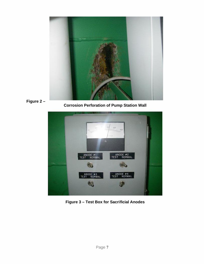
Figure 2 –Corrosion Perforation of Pump Station Wall
Figure 3 – Test Box for Sacrificial Anodes
Page 7
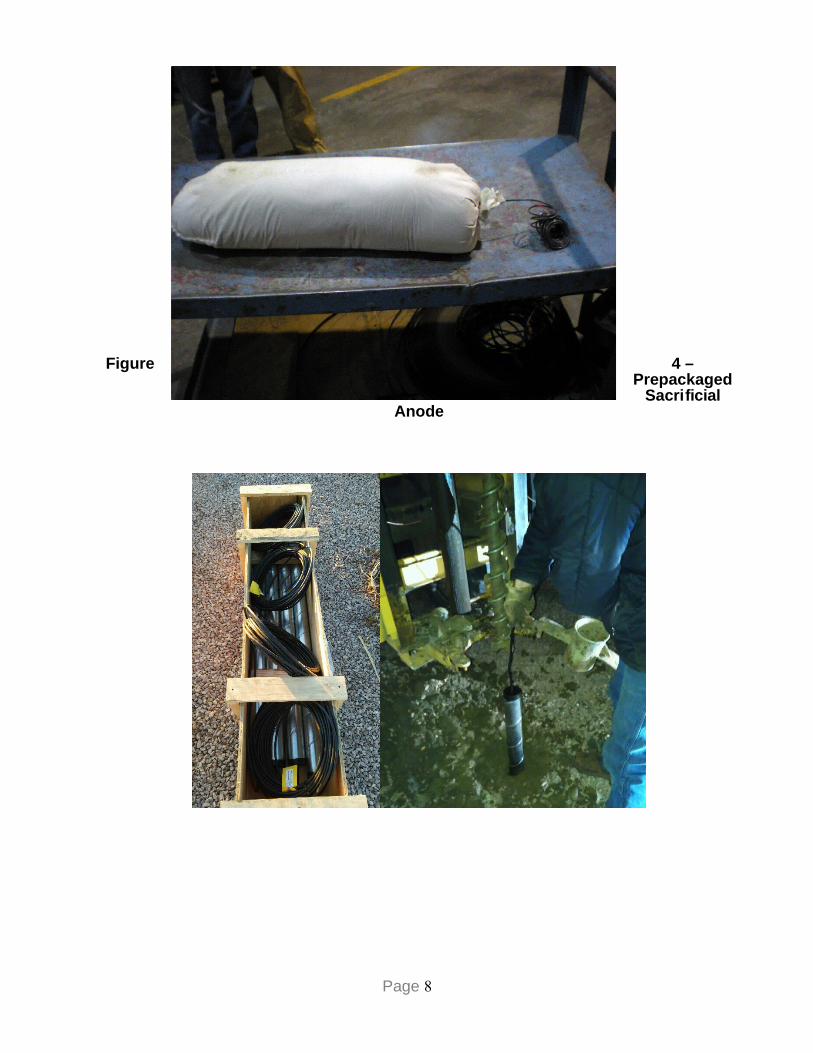
Figure 4 –Prepackaged
SacrificialAnode
Page 8
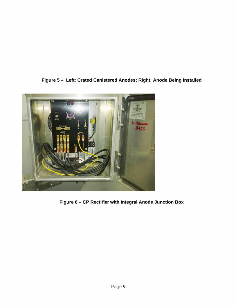
Figure 5 – Left: Crated Canistered Anodes; Right: Anode Being Installed
Figure 6 – CP Rectifier with Integral Anode Junction Box
Page 9