Embed Size (px)
Citation preview

SANDIA REPORT SAND2014-0602C Unlimited Release Printed February 2014
Corrosion and Erosion Behavior in Supercritical CO2 Power Cycles
Darryn D. Fleming, James J. Pasch, Thomas M. Conboy, Matt D. Carlson, Alan M. Kruizenga
Prepared by Sandia National Laboratories Albuquerque, New Mexico 87185 and Livermore, California 94550
Sandia National Laboratories is a multi-program laboratory managed and operated by Sandia Corporation, a wholly owned subsidiary of Lockheed Martin Corporation, for the U.S. Department of Energy's National Nuclear Security Administration under contract DE-AC04-94AL85000. Approved for public release; further dissemination unlimited.

2
Issued by Sandia National Laboratories, operated for the United States Department of Energy
by Sandia Corporation.
NOTICE: This report was prepared as an account of work sponsored by an agency of the
United States Government. Neither the United States Government, nor any agency thereof, nor
any of their employees, nor any of their contractors, subcontractors, or their employees, make
any warranty, express or implied, or assume any legal liability or responsibility for the
accuracy, completeness, or usefulness of any information, apparatus, product, or process
disclosed, or represent that its use would not infringe privately owned rights. Reference herein
to any specific commercial product, process, or service by trade name, trademark,
manufacturer, or otherwise, does not necessarily constitute or imply its endorsement,
recommendation, or favoring by the United States Government, any agency thereof, or any of
their contractors or subcontractors. The views and opinions expressed herein do not
necessarily state or reflect those of the United States Government, any agency thereof, or any
of their contractors.
Printed in the United States of America. This report has been reproduced directly from the best
available copy.
Available to DOE and DOE contractors from
U.S. Department of Energy
Office of Scientific and Technical Information
P.O. Box 62
Oak Ridge, TN 37831
Telephone: (865) 576-8401
Facsimile: (865) 576-5728
E-Mail: [email protected]
Online ordering: http://www.osti.gov/bridge
Available to the public from
U.S. Department of Commerce
National Technical Information Service
5285 Port Royal Rd.
Springfield, VA 22161
Telephone: (800) 553-6847
Facsimile: (703) 605-6900
E-Mail: [email protected]
Online order: http://www.ntis.gov/help/ordermethods.asp?loc=7-4-0#online

3
SAND2014-0602C
Unlimited Release
Printed February 2014
Corrosion and Erosion Behavior in Supercritical CO2 Power Cycles
Darryn D. Fleming, James J. Pasch, Thomas M. Conboy, Matthew D. Carlson
Advanced Nuclear Concepts
Alan M. Kruizenga
Materials Chemistry
Sandia National Laboratories
P.O. Box 5800
Albuquerque, New Mexico 87185-1130
Abstract
Supercritical Carbon Dioxide (S-CO2) is emerging as a potential working fluid in
power-production Brayton cycles. As a result, concerns have been raised regarding
fluid purity within the power cycle loops. Additionally, investigations into the
longevity of the S-CO2 power cycle materials are being conducted to quantify the
advantages of using S-CO2 versus other fluids, since S-CO2 promises substantially
higher efficiencies. One potential issue with S-CO2 systems is intergrannular
corrosion [1]. At this time, Sandia National Laboratories (SNL) is establishing a
materials baseline through the analysis of 1) “as received” stainless steel piping and
2) piping exposed to S-CO2 under typical operating conditions with SNL’s Brayton
systems. Results from ongoing investigations are presented.
A second issue that SNL has discovered involves substantial erosion in the turbine
blade and inlet nozzle. It is believed that this is caused by small particulates that
originate from different materials around the loop that are entrained by the S-CO2 to
the nozzle, where they impact the inlet nozzle vanes, causing erosion. We believe
that, in some way, this is linked to the purity of the S-CO2, the corrosion
contaminants, and the metal particulates that are present in the loop and its
components.

4
THIS PAGE INTENTIONALLY LEFT BLANK

5
CONTENTS
Figures............................................................................................................................................. 6
Tables .............................................................................................................................................. 6
Nomenclature .................................................................................................................................. 7
1. Introduction ............................................................................................................................... 8
2. Pipe analysis.............................................................................................................................. 8
3. Erosion Samples...................................................................................................................... 13
4. Nozzle Analysis ...................................................................................................................... 17
5. Conclusion .............................................................................................................................. 18
6. Acknowledgements ................................................................................................................. 19
7. References ............................................................................................................................... 20 Electronic Distribution ............................................................................................................ 22

6
FIGURES
Figure 2-1: Two SEM images of the in-service SS 316L piping showing significant
intergrannular corrosion and pitting. ........................................................................... 9 Figure 2-2: Sample location in schematic view (a) Sample location in physical view (b),
corrosion sample removed (c). .................................................................................. 11
Figure 2-3: 100x (upper) and 500x (lower) images indicate surface features indicative of
intergrannular attack. Some surface scale was observed and will be identified using
electron spectroscopy techniques. ............................................................................. 12 Figure 3-1: Turbine nozzle with substantial amount of erosion, .................................................. 14
Figure 3-2: Compressor and compressor diffuser showing signs ................................................. 15 Figure 3-3: Erosion on the Turbine, particulate erosion on turbine blade .................................... 16 Figure 3-4: SEM showing different microstructure ...................................................................... 17
Figure 4-1: Turbine Nozzle with undercut and the EDS .............................................................. 18
TABLES
Table 3-1. EDS comparison: IN C-22 vs. actual on turbine wheel ............................................... 17 Table 4-1. EDS comparison: IN 718 vs. actual on nozzle ............................................................ 18

7
NOMENCLATURE
BEI Backscatter Electron Imaging
°C Degrees Centigrade
CO2 Carbon Dioxide
DOE-NE U.S. Department of Energy –
Office of Nuclear Energy
EDS Energy Dispersive Spectroscopy
GEN IV Generation IV
IA Intergrannular Attack
IN Inconel
Ni Nickel
PCHE Printed Circuit Heat Exchanger
± Plus or Minus
RCBC Recompression Closed Loop
Brayton Cycle
SEM Scanning Electron Microscopy
S-CO2 Supercritical Carbon Dioxide
SNL Sandia National Laboratories
SS Stainless Steel
TAC Turbine Alternator Compressor
µm Micrometer
XS Cross-sectional
8
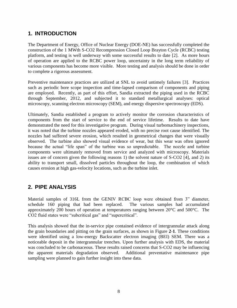
1. INTRODUCTION
The Department of Energy, Office of Nuclear Energy (DOE-NE) has successfully completed the
construction of the 1 MWth S-CO2 Recompression Closed Loop Brayton Cycle (RCBC) testing
platform, and testing is well underway with some successful results to date [2]. As more hours
of operation are applied to the RCBC power loop, uncertainty in the long term reliability of
various components has become more visible. More testing and analysis should be done in order
to complete a rigorous assessment.
Preventive maintenance practices are utilized at SNL to avoid untimely failures [3]. Practices
such as periodic bore scope inspection and time-lapsed comparison of components and piping
are employed. Recently, as part of this effort, Sandia extracted the piping used in the RCBC
through September, 2012, and subjected it to standard metallurgical analyses: optical
microscopy, scanning electron microscopy (SEM), and energy dispersive spectroscopy (EDS).
Ultimately, Sandia established a program to actively monitor the corrosion characteristics of
components from the start of service to the end of service lifetime. Results to date have
demonstrated the need for this investigative program. During visual turbomachinery inspections,
it was noted that the turbine nozzles appeared eroded, with no precise root cause identified. The
nozzles had suffered severe erosion, which resulted in geometrical changes that were visually
observed. The turbine also showed visual evidence of wear, but this wear was often ignored
because the actual “life span” of the turbine was so unpredictable. The nozzle and turbine
components were ultimately removed from service and analyzed with microscopy. Materials
issues are of concern given the following reasons 1) the solvent nature of S-CO2 [4], and 2) its
ability to transport small, dissolved particles throughout the loop, the combination of which
causes erosion at high gas-velocity locations, such as the turbine inlet.
2. PIPE ANALYSIS
Material samples of 316L from the GENIV RCBC loop were obtained from 3” diameter,
schedule 160 piping that had been replaced. The various samples had accumulated
approximately 200 hours of operation at temperatures ranging between 20°C and 500°C. The
CO2 fluid states were “subcritical gas” and “supercritical”.
This analysis showed that the in-service pipe contained evidence of intergrannular attack along
the grain boundaries and pitting on the grain surfaces, as shown in Figure 2-1. These conditions
were identified using a low-energy Backscatter electron imaging (BEI) SEM. There was a
noticeable deposit in the intergrannular trenches. Upon further analysis with EDS, the material
was concluded to be carbonaceous. These results raised concerns that S-CO2 may be influencing
the apparent materials degradation observed. Additional preventative maintenance pipe
sampling were planned to gain further insight into these data.

9
Figure 2-1: Two SEM images of the in-service SS 316L piping showing significant
intergrannular corrosion and pitting.
In early May 2013, the Brayton team decided to obtain a sample from the GEN IV S-CO2 RCBC
loop. It was determined that the leg that had the highest temperature should represent conditions
where corrosion would be the most severe in the loop. The sample was taken from the heater
outlet indicated by the red circle in Figure 2-2 (a). The sample was cut using a low-speed
reciprocating saw to avoid sample contamination from cutting oils. Cross-sectional microscopy
was used to gauge the depth of the affected base material to quantify the depth of the
intergrannular attack initially found in fresh pipe Figure 2-2 (b) shows the physical location of
the sample taken from the loop and the actual sample is shown in Figure 2-2 (c).

10
(2a)
(2b)

11
(2c)
Figure 2-2: Sample location in schematic view (a) Sample location in physical view (b),
corrosion sample removed (c).
It was apparent that the inside diameter of the pipe exhibited uniform intergrannular attack to a
depth of 15µm ± 4µm. When analyzing the sample at 500x, small amount of surface scale on the
inside diameters (IDs) of the pipe were noticeable. Scale was not uniform, and only presented
itself in small amounts on the IDs of the pipe, which indicated that corrosion was insignificant
over the range of conditions and durations that the 316L were exposed to during system
operation. Furthermore, the scale was not found in the intergrannular trenches, but rather only on
the surface, as shown in Figure 2-3.

12
Figure 2-3: 100x (upper) and 500x (lower) images indicate surface features indicative of
intergrannular attack. Some surface scale was observed and will be identified using electron
spectroscopy techniques.
Observations during the piping analysis raised questions regarding the as-received material
quality and specifications obtained on the 316L piping. The original GEN IV piping is thought
to be of lesser quality than domestic US piping material and possibly a counterfeit material.
Details about the source of the piping and the level of manufacturing quality control are still
uncertain. A pre-exposed material sample to establish a baseline was not secured, despite
repeated requests of the manufacturer. In spite of this lack of baseline data it is thought that the
13
picking process, used in removing surface scales during manufacturing, resulted in the grain
boundary trenching.
Pickling of stainless steels is a multi-step process that must be done after alloys are hot-worked
to remove oxide scales that develop on the surface. Due to their high chromium content,
stainless steels typically develop adherent, robust chromium oxide scales, which are difficult to
remove. Pickle liquors for stainless steels are thus required to utilize a variety of acid mixtures
that typically contain various concentrations or mixtures of three acids: sulfuric, nitric, and
hydrofluoric acid [5]. Lack of control during picking can result in pitting and increase in surface
roughness. Hydrofluoric acid has been shown to induce significant intergrannular attacked and
pitting on 304SS, which is compositionally similar to 316SS, in only 42 seconds [6].
In view of this information, SNL has currently benchmarked all newly installed SS 316L pipes in
the RCBC loop to keep track of the number of hours in service and will continue periodic
materials sampling. It will provide information for material requirements and pipe quality
standards related to S-CO2 systems. A mass spectrometer (Pfeiffer Vacuum Omni-Star) was
installed downstream of the heater discharge and the turbine inlet to actively monitor the relative
elemental compositions of materials being transported throughout the loop. These tests were
initially benchmarked, and the details of these tests will be presented.
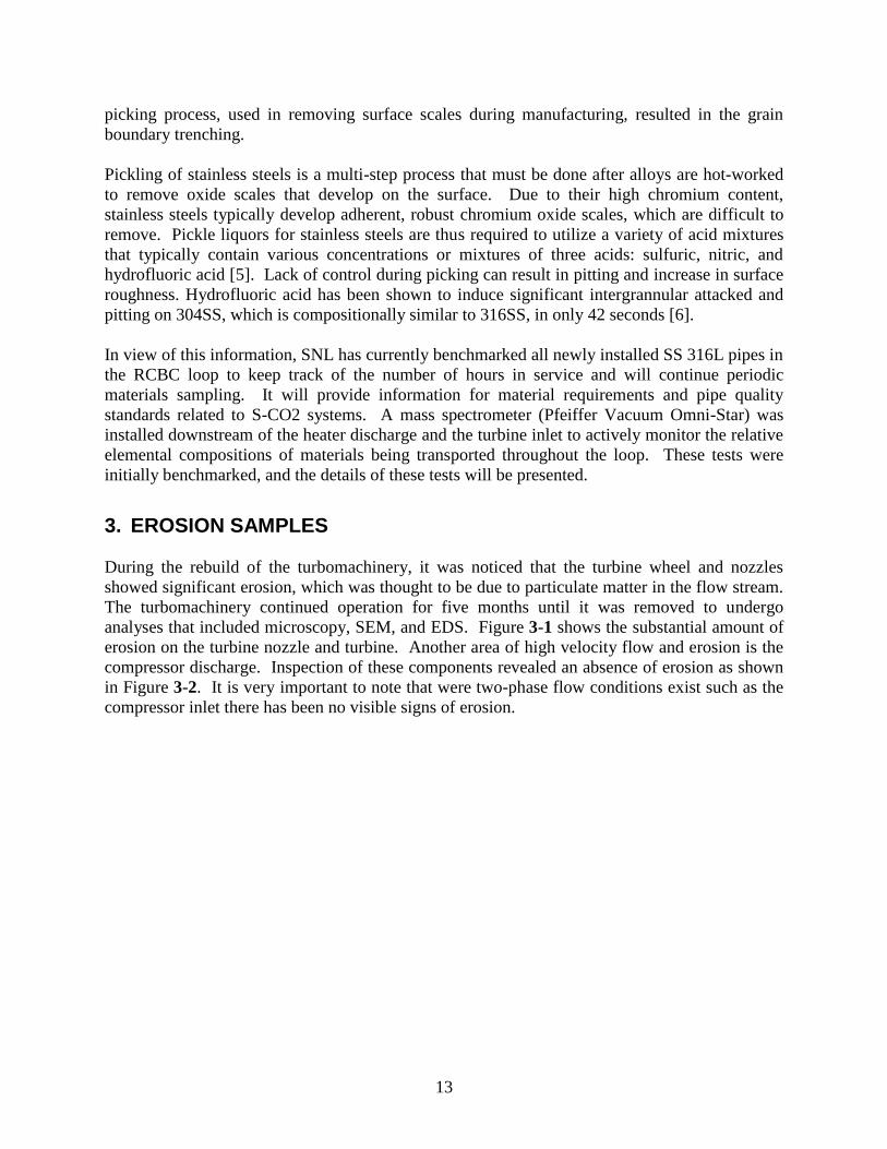
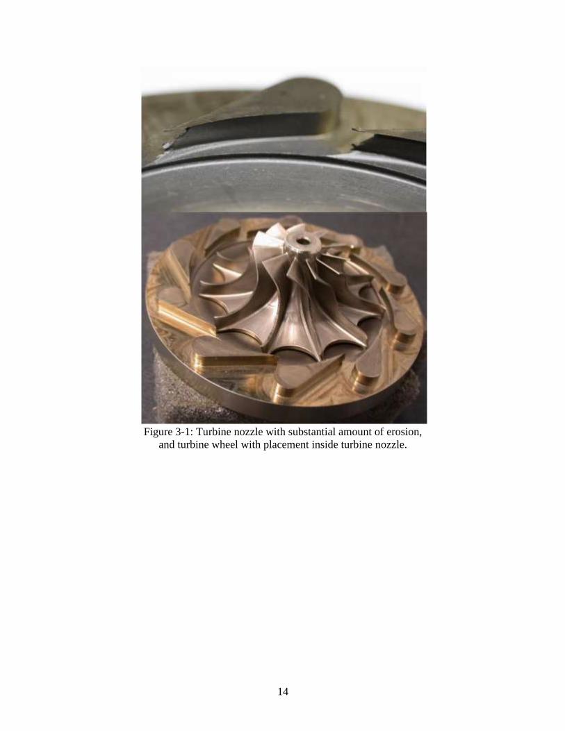
3. EROSION SAMPLES
During the rebuild of the turbomachinery, it was noticed that the turbine wheel and nozzles
showed significant erosion, which was thought to be due to particulate matter in the flow stream.
The turbomachinery continued operation for five months until it was removed to undergo
analyses that included microscopy, SEM, and EDS. Figure 3-1 shows the substantial amount of
erosion on the turbine nozzle and turbine. Another area of high velocity flow and erosion is the
compressor discharge. Inspection of these components revealed an absence of erosion as shown
in Figure 3-2. It is very important to note that were two-phase flow conditions exist such as the
compressor inlet there has been no visible signs of erosion.
14
Figure 3-1: Turbine nozzle with substantial amount of erosion,
and turbine wheel with placement inside turbine nozzle.

15
Figure 3-2: Compressor and compressor diffuser showing signs
of no erosion or liquid impingent.
Turbine analysis was accomplished using microscopy and SEM/EDS. The results from
microscopy showed substantial amounts of erosion. In addition, the inlet of the turbine wheel
showed erosion that was apparently purely mechanical, resulting from particulate erosion, as
seen in Figure 3-3. The reasoning behind the assumption of mechanical caused erosion is the
fact that we operate with high temperatures that are far in excess of the critical temperature
precluding the possibility of two-phase conditions that might lead to liquid impingement.
Furthermore, erosion occurred primarily on the suction side of the blade.

16
Figure 3-3: Erosion on the Turbine, particulate erosion on turbine blade
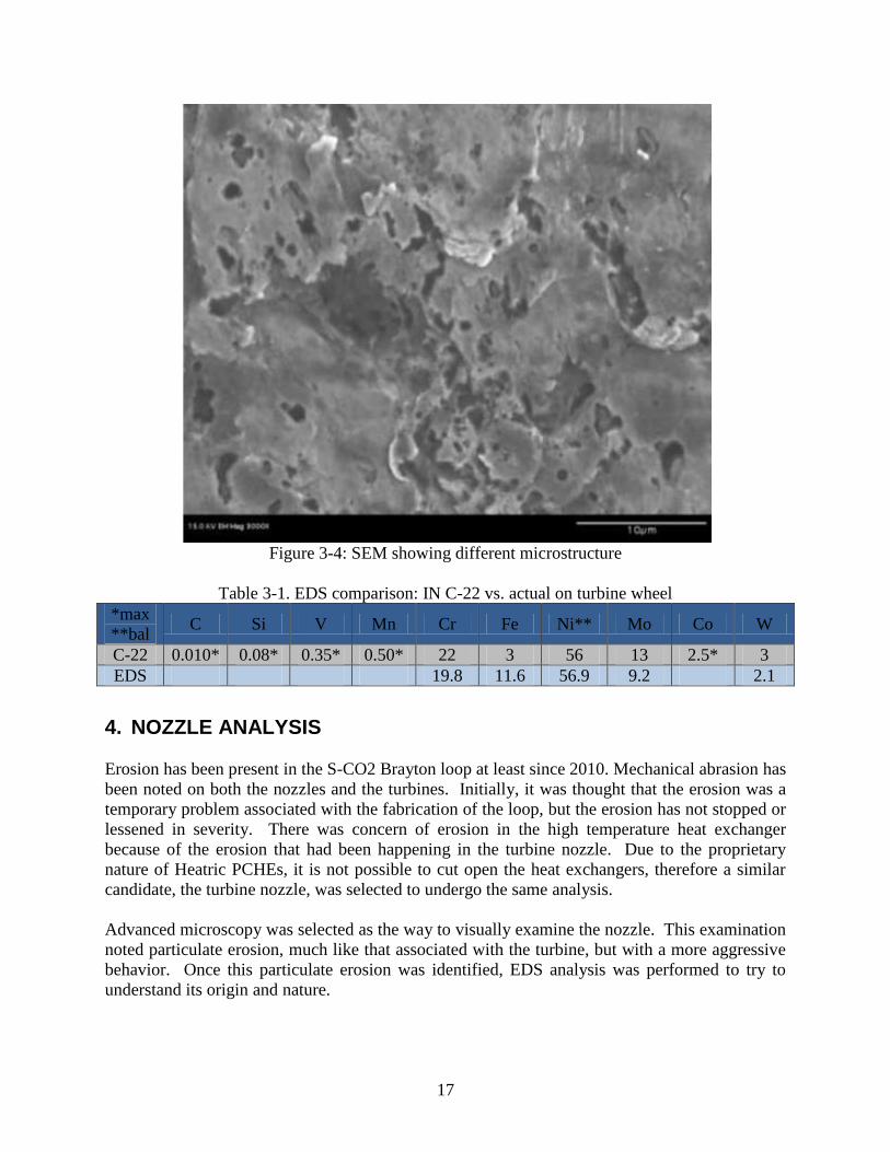
Results from the SEM, displayed in Figure 3-4, showed a different microstructure than what had
been expected. There are indications of plastic deformation from abrasion, potentially due to a
plastically deformed layer of some metal. To accurately identify the material causing abrasion,
the material composition of C-22 (the material from which the turbine was constructed) was
researched and compared it to the EDS measurement, as shown in Table 3-1. There was a high
amount of Fe present on the surface of the turbine. The current best hypothesis is that small
shavings of Ferritic steel may be the cause of the erosion.
17
Figure 3-4: SEM showing different microstructure
Table 3-1. EDS comparison: IN C-22 vs. actual on turbine wheel
*max
**bal C Si V Mn Cr Fe Ni** Mo Co W
C-22 0.010* 0.08* 0.35* 0.50* 22 3 56 13 2.5* 3
EDS 19.8 11.6 56.9 9.2 2.1
4. NOZZLE ANALYSIS
Erosion has been present in the S-CO2 Brayton loop at least since 2010. Mechanical abrasion has
been noted on both the nozzles and the turbines. Initially, it was thought that the erosion was a
temporary problem associated with the fabrication of the loop, but the erosion has not stopped or
lessened in severity. There was concern of erosion in the high temperature heat exchanger
because of the erosion that had been happening in the turbine nozzle. Due to the proprietary
nature of Heatric PCHEs, it is not possible to cut open the heat exchangers, therefore a similar
candidate, the turbine nozzle, was selected to undergo the same analysis.
Advanced microscopy was selected as the way to visually examine the nozzle. This examination
noted particulate erosion, much like that associated with the turbine, but with a more aggressive
behavior. Once this particulate erosion was identified, EDS analysis was performed to try to
understand its origin and nature.

18
Visual inspection of the sample showed extreme wastage. Figure 4-1 shows a channel eroded
out of the nozzle the height of the inlet of the turbine vane.
Figure 4-1: Turbine Nozzle with undercut and the EDS
sample location represented by red square
Following these initial observations, the nozzle underwent analysis using EDS on the undercut of
the nozzle. Because time would not permit sectioning the nozzle with a cutting technique, a
similar location was chosen for analysis (See Figure 4-1). The EDS analysis showed that there
was significant iron enrichment present on the surface, as well as a decrease in Ni. As shown in
Table 4-1, the iron content was 40.7 by percent, which was significantly higher than the expected
23.8 percent.
Table 4-1. EDS comparison: IN 718 vs. actual on nozzle
*max
**bal C Si V Mn Cr Fe Ni** Mo Co Ti Nb+Ta
IN
718 0.008* 0.35
0.35-
0.80 0.35*
17-
21
11.5-
23.8 50-55
2.8-
2.2 1.0*
0.65-
1.15
4.75-
5.50
EDS 19 40.7 35.8 3.1
5. CONCLUSION
Sandia National Laboratories is currently investigating erosion mechanisms in the recompression
closed Brayton cycle. It was found that there is currently an absence of corrosion in the S-CO2
cycle components. The initial speculation of the intergrannular attack was suspected to be
corrosion, but after careful consideration it was found the intergrannular attack was caused by an
ASTM 312 and 376 processes in which the pipe was pickle passivated in order to remove any

19
surface scale that had formed during the fabrication of the pipe. Testing will continue to look for
signs of intergrannular corrosion with well documented (hours of operation) 316L schedule 160
pipe samples.
After investigating the erosion samples from the turbine and turbine nozzle, a stronger level of
effort will be placed on the identification of the source of this damage. Currently, it is thought
that the erosion is caused by iron particulates, which are believed to come either from the
machining of loop components or from the mild steel inventory tanks. The investigation is not
limited to these sources, but it has been determined that the erosion particles are high in iron
content.
Several general strategies are being employed to respond to erosion in S-CO2 power cycles.
This includes installation of an in-situ Thermostar mass spectrometer to identify loop
contaminates. Also, erosion-resistant materials and coatings for use on the turbines and turbine
nozzles associated with these prototype systems are being investigated.
6. ACKNOWLEDGEMENTS
Sandia National Laboratories is a multi-program laboratory managed and operated by Sandia
Corporation, a wholly owned subsidiary of Lockheed Martin Corporation, for the U.S.
Department of Energy's National Nuclear Security Administration under contract DE-AC04-
94AL85000, SAND2013-6747A.

20
7. REFERENCES
1. C.H. Oh, T. Lillo, W. Windes, T. Totemeier, B. Ward, R. Moore, R. Barner,
Development Of A Supercritical Carbon Dioxide Brayton Cycle: Improving VHTR
Efficiency And Testing Material Compatibility, in: Idaho National Laboratory,
INL/EXT-06-01271, 2006.
2. J.J. Pasch, T.M. Conboy, D.D. Fleming, G.E. Rochau, Supercritical CO2 recompression
Brayton cycle : completed assembly description, in: SAND2012-9546, Sandia National
Laboratories, Albuquerque, N. M. 2012.
3. D.A. Jones, Principles and prevention of corrosion, Prentice Hall, Upper Saddle River,
NJ, 1996.
4. E.M. Russick, G.A. Poulter, C.L.J. Adkins, N.R. Sorensen, Journal of Supercritical Fluids
9 (1996) 43-43.
5. Metals Handbook Desk Edition, in: J.R. Davis (Ed.) ASM International, 2013.
6. L.-F. Li, P. Caenen, M. Daerden, D. Vaes, G. Meers, C. Dhondt, J.-P. Celis, Corrosion
Science 47 (2005) 1307-1324.

21
THIS PAGE INTENTIONALLY LEFT BLANK

22
Electronic Distribution
[email protected] Gary Rochau 06221
[email protected] Matt Carlson 06221
[email protected] Tom Conboy 06221
[email protected] Darryn Fleming 06221
[email protected] Jim Pasch 06221
[email protected] Alan Kruizenga 08223
[email protected] Technical Library 09536

23
THIS PAGE INTENTIONALLY LEFT BLANK