Embed Size (px)
DESCRIPTION
Hose
Citation preview
CorroflonC O N V O L U T E D P T F E L I N E D H O S E
• C H E M I C A L R E S I S T A N T
• S E L F - C L E A N I N G
• F L E X I B L E
• H Y G I E N I C
ContentsFront Cover Page 1
Contents Page 2
PTFE - The Optimum Choice For Hose Linings Page 3
Aflex Hose and Corroflon Page 4
Corroflon Temperatures, Pressures & Flow Rates Page 5
Corroflon Sizes, Grades, Bend Radius and Dimensions Page 6
Corroflon Sizes, Grades, Pressure Ratings and Weights Page 7
Corroflon Special Usage Conditions Page 8
Quality Assurance Certification & Approvals and Hose Testing Page 9
How to Order Corroflon Page 10
Corroflon Part Number System Page 11
HOSE
Corroflon Hose Liners Page 12
Corroflon Hose Braids (and Electrical Continuity) Page 13
Corroflon Rubber Covers Page 14
Corroflon External Protection Systems Page 15
FLANGE FITTINGS
Flange Fittings, Non-Lined Page 16
Flange Fittings, PTFE Lined Page 17
CAM AND GROOVE FITTINGS (CAMLOCKS)
Female Cam & Groove Fittings, PTFE Lined and Not Lined Page 18
Male Cam & Groove Fittings, PTFE Lined and Not Lined and Cam Male-to-Flange Adaptors, PTFE Lined Page 19
SANITARY (TRICLOVER) FITTINGS
Mini Sanitary & Sanitary Triclover Fittings, PTFE Lined Page 20
Mini Sanitary & Sanitary Triclover Fittings, Not Lined Page 21
90˚ Elbow Sanitary Triclover Fittings, Not Lined Page 22
HYGIENIC FITTINGS (EUROPEAN)
DIN11851 Male & Female Fittings, PTFE Lined and DIN11851 Female Fittings, Non-Lined Page 23
SMS and RJT Female Fittings, PTFE Lined Page 24
BSP, NPT & JIC THREADED FITTINGS (Not Lined)
NPT & BSPT Fixed Male and NPT Fixed Female Fittings Page 25
BSP 60˚ Cone Seat Female Fittings and Lug-Type Female Fittings Page 26
37˚ JIC Female Fittings & NPT Male or Female Unions Page 27
PTFE Dip Pipes
PTFE Dip Pipes, Straight or 90˚ Elbow Page 28
90˚ELBOW FITTINGS
90˚ Elbow Fittings, PTFE Lined and Non-Lined Page 29
HEAT JACKETED HOSE ASSEMBLIES
Steam Heated Hose Assemblies (CH Grade) Page 30
Electrically Trace Heated Hose Assemblies (ETH Grade) Page 31
CORROFLON STANDARD AND PURETAG LABELLING & COLOUR CODING Page 32
CORRECT HOSE CONFIGURATION & LENGTH CALCULATIONS
Bend Radius Page 33
Abrasion & Torque Page 34
Length Calculation Page 35
CONDITIONS OF SALE Pages 36 & 37
Page 2
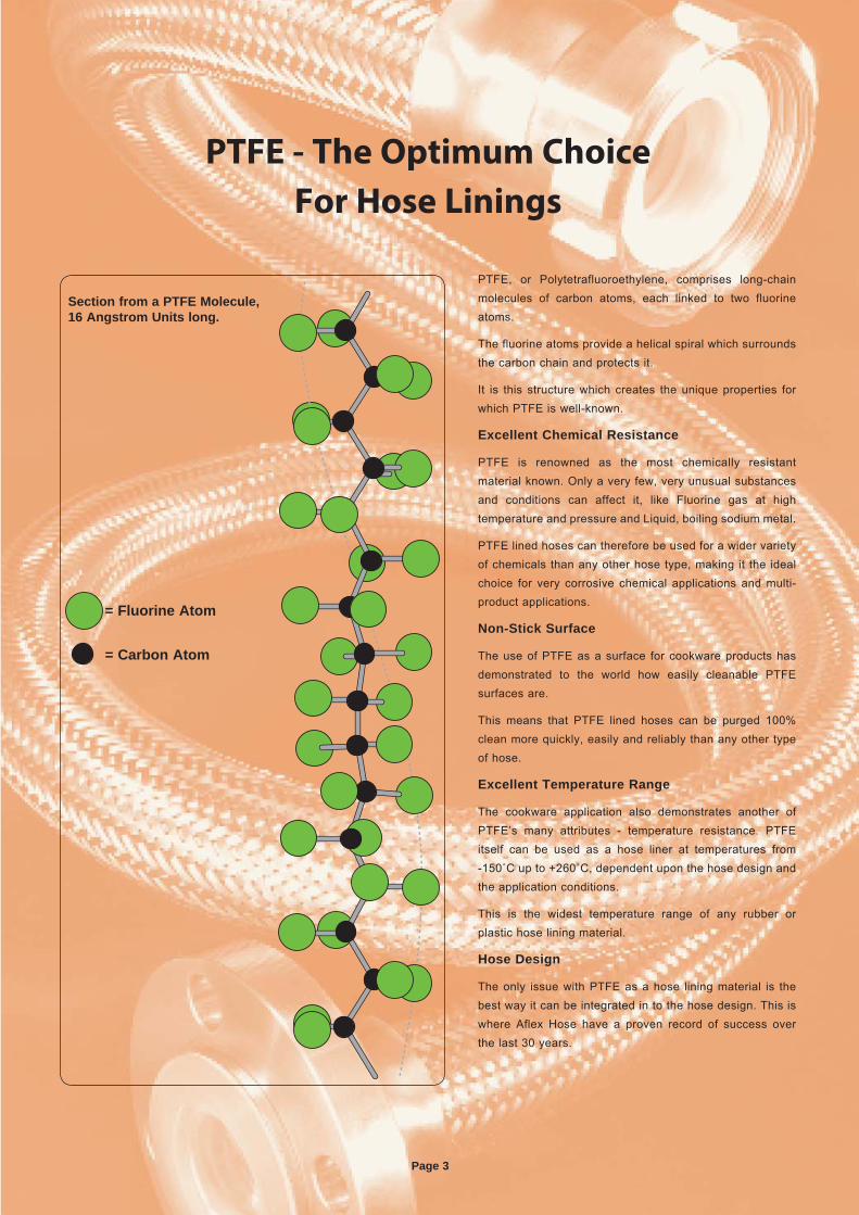
PTFE, or Polytetrafluoroethylene, comprises long-chain molecules of carbon atoms, each linked to two fluorine atoms.
The fluorine atoms provide a helical spiral which surrounds the carbon chain and protects it.
It is this structure which creates the unique properties for which PTFE is well-known.
Excellent Chemical Resistance
PTFE is renowned as the most chemically resistant material known. Only a very few, very unusual substances and conditions can affect it, like Fluorine gas at high temperature and pressure and Liquid, boiling sodium metal.
PTFE lined hoses can therefore be used for a wider variety of chemicals than any other hose type, making it the ideal choice for very corrosive chemical applications and multi-product applications.
Non-Stick Surface
The use of PTFE as a surface for cookware products has demonstrated to the world how easily cleanable PTFE surfaces are.
This means that PTFE lined hoses can be purged 100% clean more quickly, easily and reliably than any other type of hose.
Excellent Temperature Range
The cookware application also demonstrates another of PTFE’s many attributes - temperature resistance. PTFE itself can be used as a hose liner at temperatures from -150˚C up to +260˚C, dependent upon the hose design and the application conditions.
This is the widest temperature range of any rubber or plastic hose lining material.
Hose Design
The only issue with PTFE as a hose lining material is the best way it can be integrated in to the hose design. This is where Aflex Hose have a proven record of success over the last 30 years.
PTFE - The Optimum Choice
For Hose Linings
Section from a PTFE Molecule, 16 Angstrom Units long.
= Fluorine Atom
= Carbon Atom
Page 3
Page 4
Aflex Hose and CORROFLONThe World’s Leading Manufacturer of PTFE Flexible Hose
CorroflonConvoluted, Reinforced PTFE Lined Hose
Corroflon was launched in 1978 and, since then, has been continually updated and improved. Now it is the industry-standard convoluted flexible PTFE hose for major chemical, pharmaceutical and food companies worldwide.
The key to Corroflon’s success lies in its design and build quality, which guarantees a long, safe and reliable service life.
Corroflon’s design differs from every other convoluted PTFE hose on the market, which results in distinctive and measurable performance and safety advantages.
Firstly, Corroflon will give better cleanability and drainability than any other convoluted PTFE hose on the market. This is because Corroflon is designed and manufactured in such a way that the angle of the convolutions is extremely shallow - 80˚ to 120˚, compared with only 45˚ to 65˚ in other convoluted hose designs.
Secondly, Corroflon is the only PTFE lined convoluted hose on the market to be fully kink and vacuum resistant at high pressures and temperatures. This is because Corroflon’s design incorporates a thick section external helical reinforcement wire which gives the radial support necessary to ensure maximum strength, whilst maintaining optimum flexibility and cleanability. The helix wire is welded directly to the end fittings at each end, ensuring security of attachment and electrical continuity.
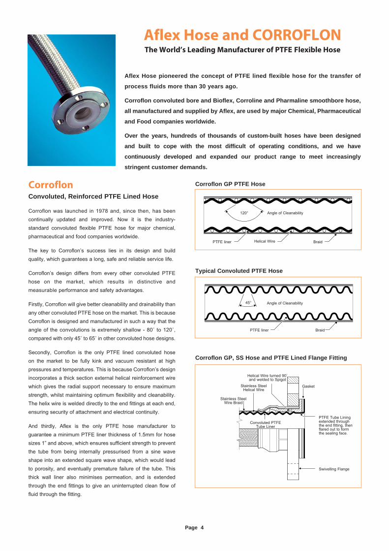
And thirdly, Aflex is the only PTFE hose manufacturer to guarantee a minimum PTFE liner thickness of 1.5mm for hose sizes 1” and above, which ensures sufficient strength to prevent the tube from being internally pressurised from a sine wave shape into an extended square wave shape, which would lead to porosity, and eventually premature failure of the tube. This thick wall liner also minimises permeation, and is extended through the end fittings to give an uninterrupted clean flow of fluid through the fitting.
Angle of Cleanability
PTFE liner Braid
45°
Typical Convoluted PTFE Hose
PTFE liner Helical Wire Braid
Angle of Cleanability120°
Corroflon GP PTFE Hose
Corroflon GP, SS Hose and PTFE Lined Flange Fitting
Aflex Hose pioneered the concept of PTFE lined flexible hose for the transfer of
process fluids more than 30 years ago.
Corroflon convoluted bore and Bioflex, Corroline and Pharmaline smoothbore hose,
all manufactured and supplied by Aflex, are used by major Chemical, Pharmaceutical
and Food companies worldwide.
Over the years, hundreds of thousands of custom-built hoses have been designed
and built to cope with the most difficult of operating conditions, and we have
continuously developed and expanded our product range to meet increasingly
stringent customer demands.
Stainless Steel Wire Braid
Stainless Steel Helical Wire
Helical Wire turned 90˚ and welded to Spigot
PTFE Tube Lining extended through the end fitting, then flared out to form the sealing face.
Swivelling Flange
Gasket
Convoluted PTFE Tube Liner
Page 5
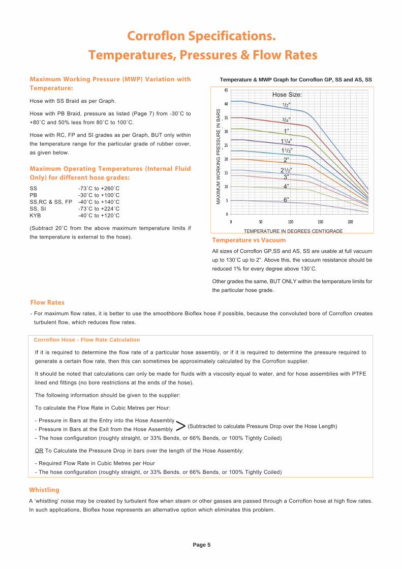
Flow Rates
- For maximum flow rates, it is better to use the smoothbore Bioflex hose if possible, because the convoluted bore of Corroflon creates turbulent flow, which reduces flow rates.
Corroflon Specifications.
Temperatures, Pressures & Flow Rates
Temperature vs Vacuum
All sizes of Corroflon GP,SS and AS, SS are usable at full vacuum up to 130˚C up to 2”. Above this, the vacuum resistance should be reduced 1% for every degree above 130˚C.
Other grades the same, BUT ONLY within the temperature limits for the particular hose grade.
Temperature & MWP Graph for Corroflon GP, SS and AS, SS
Whistling
A ‘whistling’ noise may be created by turbulent flow when steam or other gasses are passed through a Corroflon hose at high flow rates. In such applications, Bioflex hose represents an alternative option which eliminates this problem.
Corroflon Hose - Flow Rate Calculation
If it is required to determine the flow rate of a particular hose assembly, or if it is required to determine the pressure required to generate a certain flow rate, then this can sometimes be approximately calculated by the Corroflon supplier.
It should be noted that calculations can only be made for fluids with a viscosity equal to water, and for hose assemblies with PTFE lined end fittings (no bore restrictions at the ends of the hose).
The following information should be given to the supplier:
To calculate the Flow Rate in Cubic Metres per Hour:
- Pressure in Bars at the Entry into the Hose Assembly- Pressure in Bars at the Exit from the Hose Assembly- The hose configuration (roughly straight, or 33% Bends, or 66% Bends, or 100% Tightly Coiled)
OR To Calculate the Pressure Drop in bars over the length of the Hose Assembly:
- Required Flow Rate in Cubic Metres per Hour- The hose configuration (roughly straight, or 33% Bends. or 66% Bends, or 100% Tightly Coiled)
> (Subtracted to calculate Pressure Drop over the Hose Length)
Maximum Working Pressure (MWP) Variation with
Temperature:
Hose with SS Braid as per Graph.
Hose with PB Braid, pressure as listed (Page 7) from -30˚C to +80˚C and 50% less from 80˚C to 100˚C.
Hose with RC, FP and SI grades as per Graph, BUT only within the temperature range for the particular grade of rubber cover, as given below.
Maximum Operating Temperatures (Internal Fluid
Only) for different hose grades:
SS -73˚C to +260˚CPB -30˚C to +100˚CSS,RC & SS, FP -40˚C to +140˚CSS, SI -73˚C to +224˚CKYB -40˚C to +120˚C
(Subtract 20˚C from the above maximum temperature limits if the temperature is external to the hose).
MA
XIM
UM
WO
RK
ING
PR
ES
SU
RE
IN B
AR
S
TEMPERATURE IN DEGREES CENTIGRADE
Hose Size:1/2”
3/4”
1”11/4”11/2”
4”
6”
2”
21/2”3”
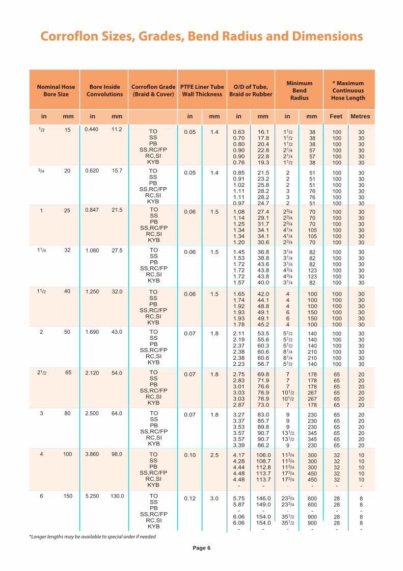
Corroflon Sizes, Grades, Bend Radius and Dimensions
Page 6
Nominal Hose
Bore Size
Bore Inside
Convolutions
Corroflon Grade
(Braid & Cover)
PTFE Liner Tube
Wall Thickness
O/D of Tube,
Braid or Rubber
Minimum
Bend
Radius
* Maximum
Continuous
Hose Length
0.07 1.8 2.752.833.013.033.032.87
69.871.976.676.976.973.0
777
101/2101/2
7
178178178267267178
656565656565
202020202020
0.05 1.4 0.630.700.800.900.900.76
16.117.820.422.822.819.3
11/211/211/221/421/411/2
383838575738
100100100100100100
303030303030
0.05 1.4 0.850.911.021.111.110.97
21.523.225.828.228.224.7
222332
515151767651
100100100100100100
303030303030
0.06 1.5 1.081.141.251.341.341.20
27.429.131.734.134.130.6
23/423/423/441/441/423/4
70707010510570
100100100100100100
303030303030
0.06 1.5 1.451.531.721.721.721.57
36.838.843.643.843.840.0
31/431/431/443/443/431/4
82828212312382
100100100100100100
303030303030
0.06 1.5 1.651.741.921.931.931.78
42.044.148.849.149.145.2
444664
100100100150150100
100100100100100100
303030303030
0.07 1.8 2.112.192.372.382.382.23
53.555.660.360.660.656.7
51/251/251/281/481/451/2
140140140210210140
100100100100100100
303030303030
0.07 1.8 3.273.373.533.573.573.39
83.085.789.890.790.786.2
999
131/2131/2
9
230230230345345230
656565656565
202020202020
0.12 3.0 5.755.87
-6.066.06
-
146.0149.0
-154.0154.0
-
233/4233/4
-351/2351/2
-
600600
-900900
-
2828-
2828-
88-88-
0.10 2.5 4.174.284.444.484.48
-
106.0108.7112.8113.7113.7
-
113/4113/4113/4173/4173/4
-
300300300450450
-
3232323232-
1010101010-
in mm in mm in mm in mm in mm Feet Metres
5.250 130.0
1/2 15
0.620 15.7
1 25
1.080 27.5
1.250 32.0
1.690 43.0
2.120 54.0
2.500 64.0
3.860 98.0
0.440 11.2 TOSSPB
SS,RC/FPRC,SIKYBTOSSPB
SS,RC/FPRC,SIKYBTOSSPB
SS,RC/FPRC,SIKYB
TOSSPB
SS,RC/FPRC,SIKYB
TOSSPB
SS,RC/FPRC,SIKYB
TOSSPB
SS,RC/FPRC,SIKYB
TOSSPB
SS,RC/FPRC,SIKYB
TOSSPB
SS,RC/FPRC,SIKYB
TOSSPB
SS,RC/FPRC,SIKYB
TOSSPB
SS,RC/FPRC,SIKYB
3/4 20
0.847 21.5
11/4 32
11/2 40
2 50
21/2 65
3 80
4 100
6 150
*Longer lengths may be available to special order if needed
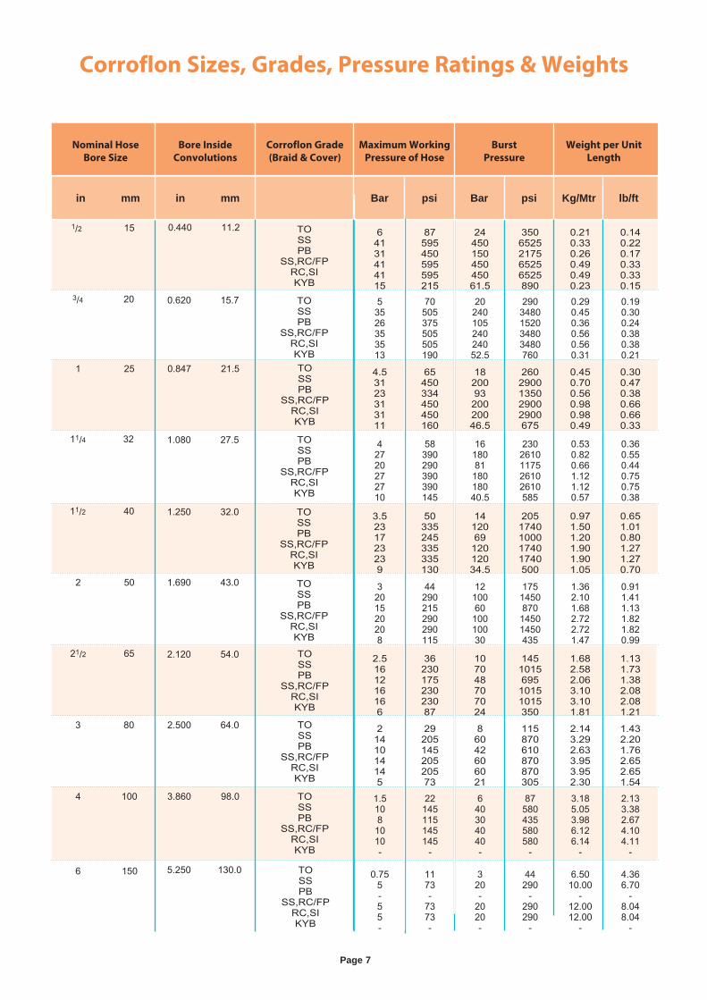
Corroflon Sizes, Grades, Pressure Ratings & Weights
Page 7
Nominal Hose
Bore Size
Bore Inside
Convolutions
Corroflon Grade
(Braid & Cover)
Maximum Working
Pressure of Hose
Burst
Pressure
Weight per Unit
Length
2.5161216166
3623017523023087
107048707024
1451015695
10151015350
1.682.582.063.103.101.81
1.131.731.382.082.081.21
64131414115
87595450595595215
2445015045045061.5
3506525217565256525890
0.210.330.260.490.490.23
0.140.220.170.330.330.15
53526353513
70505375505505190
2024010524024052.5
2903480152034803480760
0.290.450.360.560.560.31
0.190.300.240.380.380.21
4.53123313111
65450334450450160
1820093
20020046.5
2602900135029002900675
0.450.700.560.980.980.49
0.300.470.380.660.660.33
42720272710
58390290390390145
1618081
18018040.5
2302610117526102610585
0.530.820.661.121.120.57
0.360.550.440.750.750.38
3.5231723239
50335245335335130
1412069
12012034.5
2051740100017401740500
0.971.501.201.901.901.05
0.651.010.801.271.270.70
3201520208
44290215290290115
1210060
10010030
175145087014501450435
1.362.101.682.722.721.47
0.911.411.131.821.820.99
2141014145
2920514520520573
86042606021
115870610870870305
2.143.292.633.953.952.30
1.432.201.762.652.651.54
0.755-55-
1173-
7373-
320-
2020-
44290
-290290
-
6.5010.00
-12.0012.00
-
4.366.70
-8.048.04
-
1.51081010-
22145115145145
-
640304040-
87580435580580
-
3.185.053.986.126.14
-
2.133.382.674.104.11
-
in mm in mm Bar psi Bar psi Kg/Mtr lb/ft
5.250 130.0
1/2 15
0.620 15.7
1 25
1.080 27.5
1.250 32.0
1.690 43.0
2.120 54.0
2.500 64.0
3.860 98.0
0.440 11.2 TOSSPB
SS,RC/FPRC,SIKYB
TOSSPB
SS,RC/FPRC,SIKYBTOSSPB
SS,RC/FPRC,SIKYB
TOSSPB
SS,RC/FPRC,SIKYB
TOSSPB
SS,RC/FPRC,SIKYB
TOSSPB
SS,RC/FPRC,SIKYB
TOSSPB
SS,RC/FPRC,SIKYB
TOSSPB
SS,RC/FPRC,SIKYB
TOSSPB
SS,RC/FPRC,SIKYB
TOSSPB
SS,RC/FPRC,SIKYB
3/4 20
0.847 21.5
11/4 32
11/2 40
2 50
21/2 65
3 80
4 100
6 150
Page 8
Cleaning & Steril ising Systems - CIP, SIP and AutoclaveCIP & SIP – PTFE liner tubes are chemically resistant to all CIP, SIP and Autoclave conditions. The primary consideration is whether the cleaning and purging cycle is likely to develop an electrostatic charge on the internal surface of the liner, in which case AS (Anti-Static) grade hose is required.
AS grade hose and Electrostatic charge generating systems are fully described in the hose liner section.
CIP systems using high electrical resistivity solvents like Toluene will require AS grade hose.
Another electrostatic generation problem arises when wet steam is used, or when the cleaning fluids or WFI are purged out of the line using nitrogen, compressed air or another gas, because droplets of liquid or water in the gas then generate a multi-phase condition until they are cleared out, which will generate a static charge, and so will require AS grade hose.
In static generating applications where AS grade hose is not acceptable due to the black PTFE liner, alternative solutions are available – please consult Aflex Hose for advice.
Autoclave – Autoclave sterilisation does not normally involve any high flow rates through the hose bore, so static generation is not a problem. Aflex hose grades GP and AS, with SS or HB braids are fully resistant to all autoclave conditions throughout the service life of the hose.
The rubber covered grades EPDM, (RC) and Silicone Rubber (RC, SI) are able to withstand at least 100 x 30 minute autoclave cycles at relatively high autoclave temperatures (121°C, 250°F or 135°C, 275°F). Consult Aflex Hose for more specific information.
PTFE Hose-Use with Alkali Metals, Halogens and Halogen containing ChemicalsPTFE hose liners react chemically with Fluorine, Chlorine Trifluoride and molten Alkali Metals.
When PTFE lined hose is used to carry Chlorine or Bromine, either as gasses or fluids, they will diffuse into and through the PTFE liner wall thickness. Trace quantities will then combine with atmospheric moisture to corrode any braid/rubber outer coverings.
Heavily halogenated chemicals, like Hydrogen Fluoride, Hydrogen Chloride, Phosgene (Carbonyl Chloride) Carbon Tetrachloride and other organic chemicals with a high halogen content can also be absorbed and transmitted through the PTFE liner tube.
Other “Penetrating” Fluids and GasesSulphur Trioxide, Methyl Methacrylate, Caprolactam and Glacial Acetic Acid are some other chemicals which can be absorbed and transmitted through the PTFE liner tube wall.
Generally, however, as a hydrophobic (non-wetting) material, PTFE is very resistant to the absorption of chemicals. In some cases, PTFE has superior resistance to diffusion, for example to the diffusion of automotive fuels, in comparison with all other plastics and rubbers.
Gas/Fluid Cycling There are some applications where the fluid passing through the hose turns into a gas, then back into a fluid, then into a gas etc, in a cyclic sequence.
This is normally associated with changes in temperature and/or pressure. For complex reasons these conditions are extremely damaging to the hose liner, whatever material it is made from.
For example, hoses are sometimes used to pass steam, water, steam etc into rubber moulding presses, in order to heat the mould, then rapidly cool it before reheating in the next cycle. Hoses of all types fail rapidly in such an application and PTFE lined hoses are no exception.
Please contact Aflex Hose for further information if these conditions apply.
Connecting Assemblies for Use in ApplicationsThe lengths of hose assemblies and their configuration in use when connected into the application must always be in accordance with the Hose Configuration information at the end of this product literature.
When being connected for use in applications, the end fittings on hose assemblies must be connected to correct mating parts in the correct way, using the correct tools, spanners, clamps, nuts and bolts etc. The connections must be sufficiently tightened to ensure that the joint is leak free but not be over tightened as this can damage the sealing surfaces, especially with PTFE lined and flared end fittings.
In applications involving the transfer through the hose of expensive or dangerous fluids or gases, the hoses and connections must be pressure tested in situ before being put in to service. This should be done with some harmless media to 1½ times the maximum working pressure of the hose assembly, as stated in the product literature.
If in doubt please contact Aflex Hose for advice.
Special Applications
Aflex Hose PTFE lined hose products are not rated as suitable for use in the following, special applications:
All Radioactive Applications involving high energy radiation, including Gamma radiation (degrades PTFE)
All Medical Implantation Applications.
All Aerospace Applications.
Sil icone-Free Application Requirements
Some applications, particularly paint manufacturing plants, and other specialised applications require that hoses do not include any silicone containing materials in their manufacture (which is possible), or sometimes that hoses are 100% Silicone Free (which may not be possible). Customers or Distributors must identify and define any such requirements in writing on all enquiries/orders.
Corroflon Hose: Special Usage Conditions
Corroflon andQuality Assurance, Certification and Approvals,
and Hose Testing
BS EN ISO 9001:2008
Aflex products are all manufactured in accordance with BS EN ISO 9001: 2008 Quality Management Systems independently assessed and registered by National Quality Assurance Limited (NQA).
TS16949
Aflex Hose Ltd manufactures PTFE flexible hose for the automotive industry in accordance with TS16949 and is assessed and certified by National Quality Assurance Limited (NQA).
USP Class VI and ISO 10993-5, 6, 10 & 11 GUIDELINES
Natural and Antistatic PTFE Hose Liners, Platinum Cured Silicone Rubber Covers (White and Clear) and EPDM Rubber Cover (Blue) have been independently tested in accordance with USP protocols and are found to conform to the requirements of USP Class VI Chapter <88>.
Natural and Antistatic PTFE Hose Liners and Platinum Cured Silicone Rubber Covers (White and Clear) have also been tested in accordance with USP protocols and are found to conform to the requirements of USP Class VI <87>, the L929 MEM Elution Test and are considered non-cytotoxic.
FDA The Materials used to manufacture the natural PTFE Tube liner conforms to FDA 21 CFR 177.1550, and the antistatic PTFE liner conforms to FDA 21 CFR 178.3297.
3-A Sanitary Standards
The PTFE used in the liner is manufactured solely from materials which meet the requirements of the 3-A Sanitary Standards.
Pharmaceutical Manufacturers Approvals
Most of the major pharmaceutical manufacturing companies in the world have audited and/or approved Aflex Hose as a Hose Supplier.
BPSA Leachables and Extractables Testing
Aflex Hose Natural and Antistatic PTFE Hose Liner Tube has been independently tested in accordance with BPSA recommendations, and found to be satisfactory.Copies of the Test Report are available for specific assessments to be made.
CE Marking (Europe only)
Aflex has been assessed by a notified body and found to comply with the Pressure Equipment Directive 97/23/EC (European Community) Conformity Assessment Module D1, approved to CE Mark applicable hose products, accompanied by a Hose Usage Data Sheet, and a Declaration of Conformity.
Attestations of Conformity to ATEX Directive 94/9/EC (Potentially Explosive
Atmospheres)
Available for hose and assemblies for components used in Gas Zones 1 & 2 and Dust Zones 21 & 22, when applicable.
Material Certification to EN10204
Available for all the hose or hose assembly components.
Certificates of Conformity to BS EN ISO/IEC 17050
Are available for all products.
Hose Testing Each assembly is pressure tested to 1.5 times maximum working pressure before despatch, and pressure test certificates can be supplied.
Fire Resistance to BS5173 Section 103.13 Part 6.2 and 6.3
RC Grade Corroflon hose assemblies are “Fire Resistant”. If DRC-300 is added at both ends, the assemblies are upgraded to “Fire Proof”.
Page 9
Page 10
How to Order Corroflon Hose Assemblies
Selecting the Hose Length (see also pages 33 - 35)
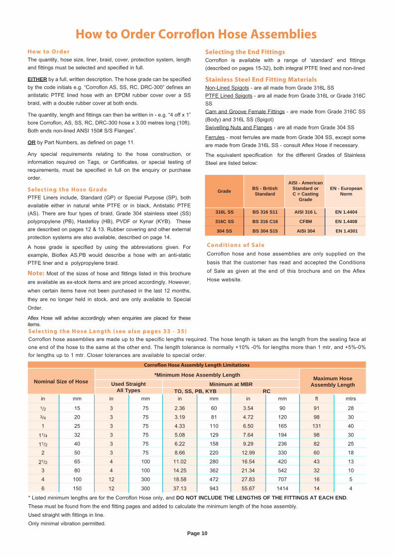
Corroflon hose assemblies are made up to the specific lengths required. The hose length is taken as the length from the sealing face at one end of the hose to the same at the other end. The length tolerance is normally +10% -0% for lengths more than 1 mtr, and +5%-0% for lengths up to 1 mtr. Closer tolerances are available to special order.
Conditions of Sale
Corroflon hose and hose assemblies are only supplied on the basis that the customer has read and accepted the Conditions of Sale as given at the end of this brochure and on the Aflex Hose website.
Selecting the End Fittings
Corroflon is available with a range of ‘standard’ end fittings (described on pages 15-32), both integral PTFE lined and non-lined
Stainless Steel End Fitting Materials
Non-Lined Spigots - are all made from Grade 316L SSPTFE Lined Spigots - are all made from Grade 316L or Grade 316C SSCam and Groove Female Fittings - are made from Grade 316C SS (Body) and 316L SS (Spigot)Swivelling Nuts and Flanges - are all made from Grade 304 SS
Ferrules - most ferrules are made from Grade 304 SS, except some are made from Grade 316L SS - consult Aflex Hose if necessary.
The equivalent specification for the different Grades of Stainless Steel are listed below:
How to Order
The quantity, hose size, liner, braid, cover, protection system, length and fittings must be selected and specified in full.
EITHER by a full, written description. The hose grade can be specified by the code initials e.g. “Corroflon AS, SS, RC, DRC-300” defines an antistatic PTFE lined hose with an EPDM rubber cover over a SS braid, with a double rubber cover at both ends.
The quantity, length and fittings can then be written in - e.g. “4 off x 1” bore Corroflon, AS, SS, RC, DRC-300 hose x 3.00 metres long (10ft). Both ends non-lined ANSI 150# S/S Flanges”.
OR by Part Numbers, as defined on page 11.
Any special requirements relating to the hose construction, or information required on Tags, or Certificates, or special testing of requirements, must be specified in full on the enquiry or purchase order.
Selecting the Hose Grade
PTFE Liners include, Standard (GP) or Special Purpose (SP), both available either in natural white PTFE or in black, Antistatic PTFE (AS). There are four types of braid, Grade 304 stainless steel (SS) polypropylene (PB), Hastelloy (HB), PVDF or Kynar (KYB). These are described on pages 12 & 13. Rubber covering and other external protection systems are also available, described on page 14.
A hose grade is specified by using the abbreviations given. For example, Bioflex AS,PB would describe a hose with an anti-static PTFE liner and a polypropylene braid.
Note: Most of the sizes of hose and fittings listed in this brochure are available as ex-stock items and are priced accordingly. However, when certain items have not been purchased in the last 12 months, they are no longer held in stock, and are only available to Special Order.
Aflex Hose will advise accordingly when enquiries are placed for these items.
Grade BS - British Standard
AISI - American Standard or C = Casting
Grade
EN - European Norm
316L SS BS 316 S11 AISI 316 L EN 1.4404
316C SS BS 316 C16 CF8M EN 1.4408
304 SS BS 304 S15 AISI 304 EN 1.4301
* Listed minimum lengths are for the Corroflon Hose only, and DO NOT INCLUDE THE LENGTHS OF THE FITTINGS AT EACH END.These must be found from the end fitting pages and added to calculate the minimum length of the hose assembly.Used straight with fittings in line.Only minimal vibration permitted.
Maximum Hose Assembly LengthNominal Size of Hose
Corroflon Hose Assembly Length Limitations
Minimum at MBRUsed StraightAll Types
*Minimum Hose Assembly Length
in mm in mm in mm in mm ft mtrs
1/2 15 3 75 2.36 60 3.54 90 91 283/4 20 3 75 3.19 81 4.72 120 98 30
1 25 3 75 4.33 110 6.50 165 131 40
11/4 32 3 75 5.08 129 7.64 194 98 30
11/2 40 3 75 6.22 158 9.29 236 82 25
2 50 3 75 8.66 220 12.99 330 60 18
21/2 65 4 100 11.02 280 16.54 420 43 13
3 80 4 100 14.25 362 21.34 542 32 10
4 100 12 300 18.58 472 27.83 707 16 5
6 150 12 300 37.13 943 55.67 1414 14 4
TO, SS, PB, KYB RC
Page 11
Corroflon Hose Assembly Part Number System
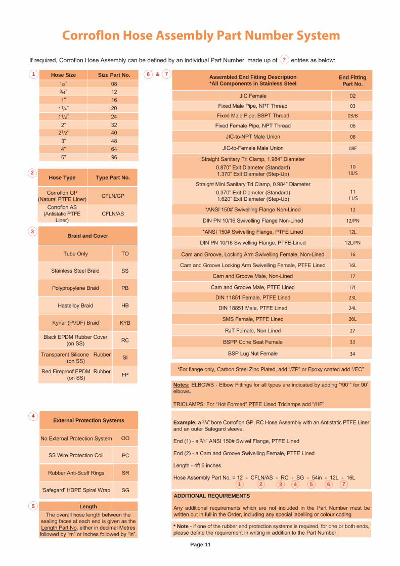
If required, Corroflon Hose Assembly can be defined by an individual Part Number, made up of 7 entries as below:
Hose Size Size Part No.1/2” 083/4” 121” 16
11/4” 2011/2” 242” 32
21/2” 403” 48
6” 964” 64
LengthThe overall hose length between the
sealing faces at each end is given as the Length Part No, either in decimal Metres followed by “m” or Inches followed by “in”.
ADDITIONAL REQUIREMENTS
Any additional requirements which are not included in the Part Number must be written out in full in the Order, including any special labelling or colour coding
1 6 & 7
2
Assembled End Fitting Description*All Components in Stainless Steel
End Fitting Part No.
JIC Female 02
Fixed Male Pipe, NPT Thread 03
Fixed Male Pipe, BSPT Thread 03/B
Fixed Female Pipe, NPT Thread 06
JIC-to-NPT Male Union 08
Notes: ELBOWS - Elbow Fittings for all types are indicated by adding “/90˚” for 90˚ elbows.
TRICLAMPS: For “Hot Formed” PTFE Lined Triclamps add “/HF”
JIC-to-Female Male Union 08F
Straight Sanitary Tri Clamp, 1.984” Diameter0.870” Exit Diameter (Standard)1.370” Exit Diameter (Step-Up)
1010/S
Straight Mini Sanitary Tri Clamp, 0.984” Diameter0.370” Exit Diameter (Standard)1.620” Exit Diameter (Step-Up)
1111/S
Example: a 3/4” bore Corroflon GP, RC Hose Assembly with an Antistatic PTFE Liner and an outer Safegard sleeve.
End (1) - a 3/4” ANSI 150# Swivel Flange, PTFE Lined
End (2) - a Cam and Groove Swivelling Female, PTFE Lined
Length - 4ft 6 inches
Hose Assembly Part No. = 12 - CFLN/AS - RC - SG - 54in - 12L - 16L
*For flange only, Carbon Steel Zinc Plated, add “/ZP” or Epoxy coated add “/EC”
1 2 3 4 5 6 7
5
4External Protection Systems
No External Protection System
SS Wire Protection Coil
Rubber Anti-Scuff Rings
OO
PC
SR
‘Safegard’ HDPE Spiral Wrap SG
*ANSI 150# Swivelling Flange Non-Lined 12
DIN PN 10/16 Swivelling Flange Non-Lined 12/PN
*ANSI 150# Swivelling Flange, PTFE Lined 12L
DIN PN 10/16 Swivelling Flange, PTFE-Lined 12L/PN
Cam and Groove, Locking Arm Swivelling Female, Non-Lined 16
Cam and Groove Locking Arm Swivelling Female, PTFE Lined 16L
Cam and Groove Male, Non-Lined 17
Cam and Groove Male, PTFE Lined 17L
DIN 11851 Female, PTFE Lined 23L
DIN 18851 Male, PTFE Lined 24L
SMS Female, PTFE Lined 26L
RJT Female, Non-Lined 27
BSPP Cone Seat Female 33
BSP Lug Nut Female 34
Hose Type Type Part No.
Corroflon GP (Natural PTFE Liner) CFLN/GP
Corroflon AS (Antistatic PTFE
Liner)CFLN/AS
* Note - if one of the rubber end protection systems is required, for one or both ends, please define the requirement in writing in addition to the Part Number.
3Braid and Cover
Tube Only
Stainless Steel Braid
Polypropylene Braid
Hastelloy Braid
Kynar (PVDF) Braid
Black EPDM Rubber Cover (on SS)
Red Fireproof EPDM Rubber (on SS)
Transparent Silicone Rubber (on SS)
TO
SS
PB
HB
KYB
RC
FP
SI
Page 12
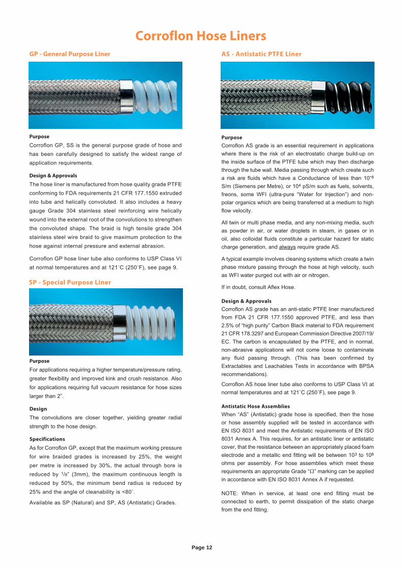
Corroflon Hose Liners
Purpose
Corroflon GP, SS is the general purpose grade of hose and has been carefully designed to satisfy the widest range of application requirements.
Design & Approvals
The hose liner is manufactured from hose quality grade PTFEconforming to FDA requirements 21 CFR 177.1550 extruded into tube and helically convoluted. It also includes a heavy gauge Grade 304 stainless steel reinforcing wire helically wound into the external root of the convolutions to strengthen the convoluted shape. The braid is high tensile grade 304 stainless steel wire braid to give maximum protection to the hose against internal pressure and external abrasion.
Corroflon GP hose liner tube also conforms to USP Class VI at normal temperatures and at 121˚C (250˚F), see page 9.
Purpose
For applications requiring a higher temperature/pressure rating, greater flexibility and improved kink and crush resistance. Also for applications requiring full vacuum resistance for hose sizes larger than 2”.
Design
The convolutions are closer together, yielding greater radial strength to the hose design.
Specifications
As for Corroflon GP, except that the maximum working pressure for wire braided grades is increased by 25%, the weight per metre is increased by 30%, the actual through bore is reduced by 1/8” (3mm), the maximum continuous length is reduced by 50%, the minimum bend radius is reduced by 25% and the angle of cleanability is <80˚.
Available as SP (Natural) and SP, AS (Antistatic) Grades.
Purpose
Corroflon AS grade is an essential requirement in applications where there is the risk of an electrostatic charge build-up on the inside surface of the PTFE tube which may then discharge through the tube wall. Media passing through which create such a risk are fluids which have a Conductance of less than 10-8 S/m (Siemens per Metre), or 104 pS/m such as fuels, solvents, freons, some WFI (ultra-pure “Water for Injection”) and non-polar organics which are being transferred at a medium to high flow velocity.
All twin or multi phase media, and any non-mixing media, such as powder in air, or water droplets in steam, in gases or in oil, also colloidal fluids constitute a particular hazard for static charge generation, and always require grade AS.
A typical example involves cleaning systems which create a twin phase mixture passing through the hose at high velocity, such as WFI water purged out with air or nitrogen.
If in doubt, consult Aflex Hose.
Design & Approvals
Corroflon AS grade has an anti-static PTFE liner manufactured from FDA 21 CFR 177.1550 approved PTFE, and less than 2.5% of “high purity” Carbon Black material to FDA requirement 21 CFR 178.3297 and European Commission Directive 2007/19/EC. The carbon is encapsulated by the PTFE, and in normal, non-abrasive applications will not come loose to contaminate any fluid passing through. (This has been confirmed by Extractables and Leachables Tests in accordance with BPSA recommendations).
Corroflon AS hose liner tube also conforms to USP Class VI at normal temperatures and at 121˚C (250˚F), see page 9.
Antistatic Hose Assemblies
When “AS” (Antistatic) grade hose is specified, then the hose or hose assembly supplied will be tested in accordance with EN ISO 8031 and meet the Antistatic requirements of EN ISO 8031 Annex A. This requires, for an antistatic liner or antistatic cover, that the resistance between an appropriately placed foam electrode and a metallic end fitting will be between 103 to 108 ohms per assembly. For hose assemblies which meet these requirements an appropriate Grade “Ω” marking can be applied in accordance with EN ISO 8031 Annex A if requested.
NOTE: When in service, at least one end fitting must be connected to earth, to permit dissipation of the static charge from the end fitting.
GP - General Purpose Liner AS - Antistatic PTFE Liner
SP - Special Purpose Liner
Page 13
Corroflon Hose Braids
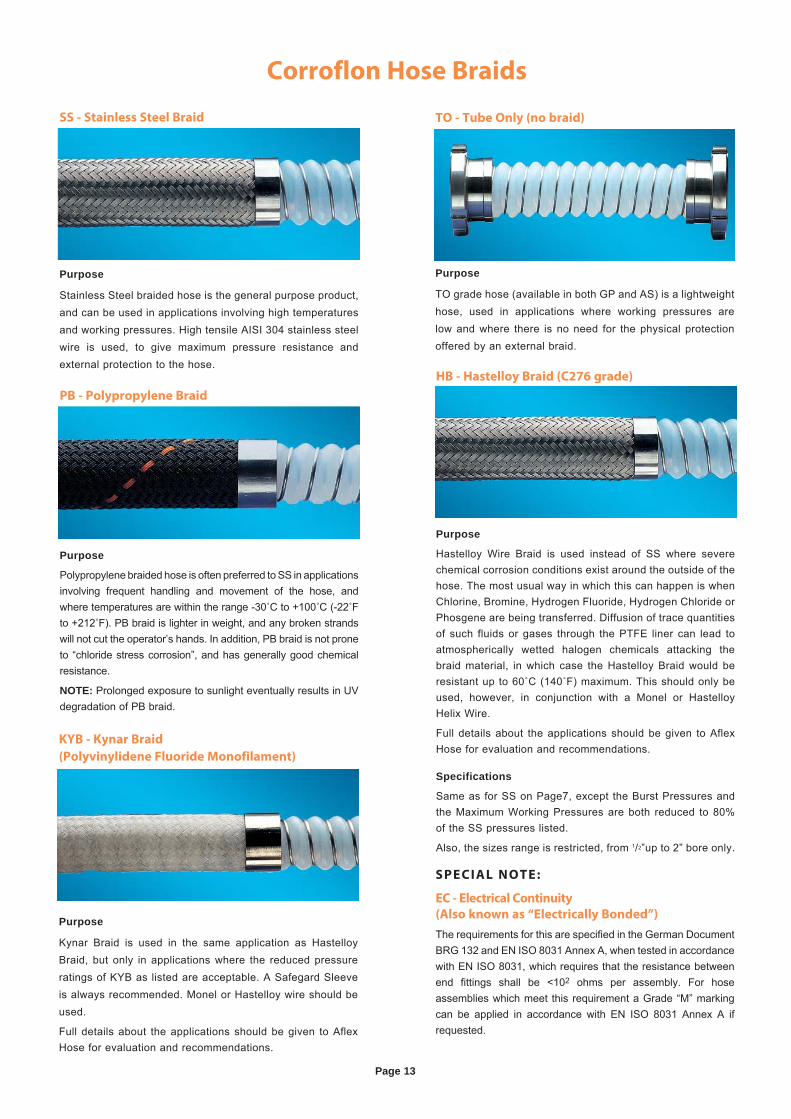
Purpose
TO grade hose (available in both GP and AS) is a lightweight hose, used in applications where working pressures are low and where there is no need for the physical protection offered by an external braid.
Purpose
Polypropylene braided hose is often preferred to SS in applications involving frequent handling and movement of the hose, and where temperatures are within the range -30˚C to +100˚C (-22˚F to +212˚F). PB braid is lighter in weight, and any broken strands will not cut the operator’s hands. In addition, PB braid is not prone to “chloride stress corrosion”, and has generally good chemical resistance.
NOTE: Prolonged exposure to sunlight eventually results in UV degradation of PB braid.
Purpose
Kynar Braid is used in the same application as Hastelloy Braid, but only in applications where the reduced pressure ratings of KYB as listed are acceptable. A Safegard Sleeve is always recommended. Monel or Hastelloy wire should be used.
Full details about the applications should be given to Aflex Hose for evaluation and recommendations.
TO - Tube Only (no braid)
PB - Polypropylene Braid
Purpose
Stainless Steel braided hose is the general purpose product, and can be used in applications involving high temperatures and working pressures. High tensile AISI 304 stainless steel wire is used, to give maximum pressure resistance and external protection to the hose.
SS - Stainless Steel Braid
SPECIAL NOTE:
EC - Electrical Continuity
(Also known as “Electrically Bonded”)
The requirements for this are specified in the German Document BRG 132 and EN ISO 8031 Annex A, when tested in accordance with EN ISO 8031, which requires that the resistance between end fittings shall be <102 ohms per assembly. For hose assemblies which meet this requirement a Grade “M” marking can be applied in accordance with EN ISO 8031 Annex A if requested.
Purpose
Hastelloy Wire Braid is used instead of SS where severe chemical corrosion conditions exist around the outside of the hose. The most usual way in which this can happen is when Chlorine, Bromine, Hydrogen Fluoride, Hydrogen Chloride or Phosgene are being transferred. Diffusion of trace quantities of such fluids or gases through the PTFE liner can lead to atmospherically wetted halogen chemicals attacking the braid material, in which case the Hastelloy Braid would be resistant up to 60˚C (140˚F) maximum. This should only be used, however, in conjunction with a Monel or Hastelloy Helix Wire.
Full details about the applications should be given to Aflex Hose for evaluation and recommendations.
Specifications
Same as for SS on Page7, except the Burst Pressures and the Maximum Working Pressures are both reduced to 80% of the SS pressures listed.
Also, the sizes range is restricted, from 1/2”up to 2” bore only.
HB - Hastelloy Braid (C276 grade)
KYB - Kynar Braid
(Polyvinylidene Fluoride Monofilament)
Page 14
Corroflon Rubber Covers
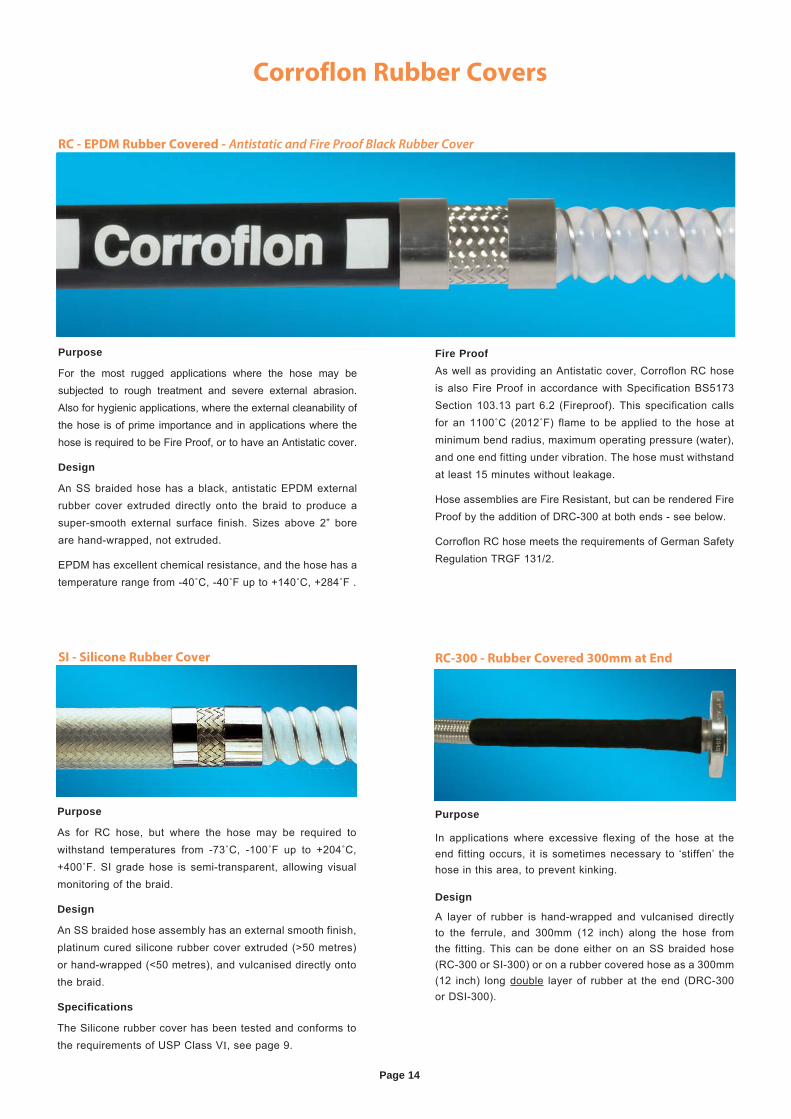
RC - EPDM Rubber Covered - Antistatic and Fire Proof Black Rubber Cover
Purpose
As for RC hose, but where the hose may be required to withstand temperatures from -73˚C, -100˚F up to +204˚C, +400˚F. SI grade hose is semi-transparent, allowing visual monitoring of the braid.
Design
An SS braided hose assembly has an external smooth finish, platinum cured silicone rubber cover extruded (>50 metres) or hand-wrapped (<50 metres), and vulcanised directly onto the braid.
Specifications
The Silicone rubber cover has been tested and conforms to the requirements of USP Class VI, see page 9.
SI - Silicone Rubber Cover
Purpose
In applications where excessive flexing of the hose at the end fitting occurs, it is sometimes necessary to ‘stiffen’ the hose in this area, to prevent kinking.
Design
A layer of rubber is hand-wrapped and vulcanised directly to the ferrule, and 300mm (12 inch) along the hose from the fitting. This can be done either on an SS braided hose (RC-300 or SI-300) or on a rubber covered hose as a 300mm (12 inch) long double layer of rubber at the end (DRC-300 or DSI-300).
RC-300 - Rubber Covered 300mm at End
Purpose
For the most rugged applications where the hose may be subjected to rough treatment and severe external abrasion. Also for hygienic applications, where the external cleanability of the hose is of prime importance and in applications where the hose is required to be Fire Proof, or to have an Antistatic cover.
Design
An SS braided hose has a black, antistatic EPDM external rubber cover extruded directly onto the braid to produce a super-smooth external surface finish. Sizes above 2” bore are hand-wrapped, not extruded.
EPDM has excellent chemical resistance, and the hose has a temperature range from -40˚C, -40˚F up to +140˚C, +284˚F .
Fire ProofAs well as providing an Antistatic cover, Corroflon RC hose is also Fire Proof in accordance with Specification BS5173 Section 103.13 part 6.2 (Fireproof). This specification calls for an 1100˚C (2012˚F) flame to be applied to the hose at minimum bend radius, maximum operating pressure (water), and one end fitting under vibration. The hose must withstand at least 15 minutes without leakage.
Hose assemblies are Fire Resistant, but can be rendered Fire Proof by the addition of DRC-300 at both ends - see below.
Corroflon RC hose meets the requirements of German Safety Regulation TRGF 131/2.
Page 15
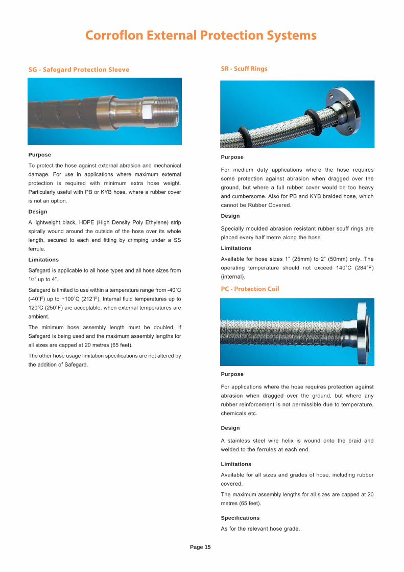
Corroflon External Protection Systems
Purpose
For medium duty applications where the hose requires some protection against abrasion when dragged over the ground, but where a full rubber cover would be too heavy and cumbersome. Also for PB and KYB braided hose, which cannot be Rubber Covered.
Design
Specially moulded abrasion resistant rubber scuff rings are placed every half metre along the hose.
Limitations
Available for hose sizes 1” (25mm) to 2” (50mm) only. The operating temperature should not exceed 140˚C (284˚F) (internal).
SR - Scuff Rings
Purpose
For applications where the hose requires protection against abrasion when dragged over the ground, but where any rubber reinforcement is not permissible due to temperature, chemicals etc.
Design
A stainless steel wire helix is wound onto the braid and welded to the ferrules at each end.
Limitations
Available for all sizes and grades of hose, including rubber covered.
The maximum assembly lengths for all sizes are capped at 20 metres (65 feet).
Specifications
As for the relevant hose grade.
PC - Protection Coil
SG - Safegard Protection Sleeve
Purpose
To protect the hose against external abrasion and mechanical damage. For use in applications where maximum external protection is required with minimum extra hose weight. Particularly useful with PB or KYB hose, where a rubber cover is not an option.
Design
A lightweight black, HDPE (High Density Poly Ethylene) strip spirally wound around the outside of the hose over its whole length, secured to each end fitting by crimping under a SS ferrule.
Limitations
Safegard is applicable to all hose types and all hose sizes from 1/2” up to 4”.
Safegard is limited to use within a temperature range from -40˚C (-40˚F) up to +100˚C (212˚F). Internal fluid temperatures up to 120˚C (250˚F) are acceptable, when external temperatures are ambient.
The minimum hose assembly length must be doubled, if Safegard is being used and the maximum assembly lengths for all sizes are capped at 20 metres (65 feet).
The other hose usage limitation specifications are not altered by the addition of Safegard.
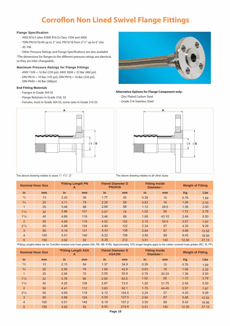
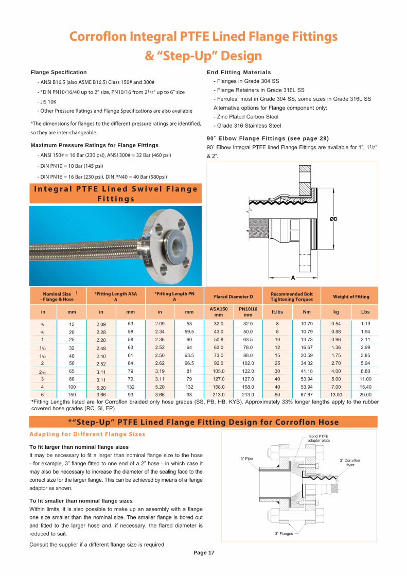
Flange Specification - ANSI B16.5 (also ASME B16.5) Class 150# and 300#
- *DIN PN10/16/40 up to 2” size, PN10/16 from 21/2” up to 6” size
- JIS 10K
- Other Pressure Ratings and Flange Specifications are also available
*The dimensions for flanges to the different pressure ratings are identical, so they are inter-changeable.
Maximum Pressure Ratings for Flange Fittings - ANSI 150# = 16 Bar (230 psi), ANSI 300# = 32 Bar (460 psi)
- DIN PN10 = 10 Bar (145 psi), DIN PN16 = 16 Bar (230 psi), DIN PN40 = 40 Bar (580psi)
End Fitting Materials
- Flanges in Grade 304 SS
- Flange Retainers in Grade 316L SS
- Ferrules, most in Grade 304 SS, some sizes in Grade 316 SS
Alternative Options for Flange Component only:
- Zinc Plated Carbon Steel
- Grade 316 Stainless Steel
Page 16
Corroflon Non Lined Swivel Flange Fittings
*Fitting Lengths listed are for Corroflon braided only hose grades (SS, PB, HB, KYB). Approximately 33% longer lengths apply to the rubber covered hose grades (RC, SI, FP).
Nominal Hose Size *Fitting Length PNA
Flared Diameter DPN10/16
Fitting Inside Diameter I
Weight of Fitting
in mm in mm in mm in mm Kg Lbs1/2 13 2.20 56 1.77 45 0.39 10 0.76 1.693/4 20 3.11 79 2.28 58 0.63 16 1.06 2.351 25 3.46 88 2.68 68 1.12 28.5 1.36 3.00
11/2 40 4.69 119 3.46 88 1.69 43.10 2.49 5.502 50 4.69 119 4.02 102 2.15 54.5 3.57 7.87
21/2 65 4.88 124 4.80 122 2.24 57 4.20 9.263 80 5.16 131 5.43 138 2.64 67 5.68 12.524 100 5.51 140 6.22 158 3.50 89 8.42 18.566 150 3.62 92 8.35 212 5.51 140 12.30 27.12
11/4 32 3.98 101 3.07 78 1.02 26 1.72 3.79
Nominal Hose Size *Fitting Length ASAA
Flared Diameter DASA150
Fitting Inside Diameter I Weight of Fitting
in mm in mm in mm in mm Kg Lbs1/2 13 2.13 54 1.37 34.9 0.39 10 0.76 1.693/4 20 2.99 76 1.69 42.9 0.63 16 1.06 2.351 25 2.95 75 2.00 50.8 0.79 20.24 1.36 3.00
11/2 40 4.25 108 2.87 73.0 1.25 31.75 2.49 5.502 50 4.41 112 3.63 92.1 1.75 44.45 3.57 7.87
21/2 65 4.65 118 4.12 104.5 2.24 57 4.20 9.263 80 4.88 124 5.00 127.0 2.64 67 5.68 12.524 100 5.51 140 6.19 157.2 3.50 89 8.42 18.566 150 3.62 92 8.50 215.9 5.51 140 12.30 27.12
11/4 32 3.78 96 2.50 63.5 1.02 26 1.72 3.79
The above drawing relates to sizes 1", 11/2", 2" The above drawing relates to all other sizes
Corroflon Integral PTFE Lined Flange Fittings
& “Step-Up” Design
Solid PTFE adaptor plate
2” Corroflon Hose
3” Flanges
3” Pipe
Adapting for Different Flange Sizes
To fit larger than nominal flange sizesIt may be necessary to fit a larger than nominal flange size to the hose - for example, 3” flange fitted to one end of a 2” hose - in which case it may also be necessary to increase the diameter of the sealing face to the correct size for the larger flange. This can be achieved by means of a flange adaptor as shown.
To fit smaller than nominal flange sizesWithin limits, it is also possible to make up an assembly with a flange one size smaller than the nominal size. The smaller flange is bored out and fitted to the larger hose and, if necessary, the flared diameter is reduced to suit.
Consult the supplier if a different flange size is required.
Flange Specification
- ANSI B16.5 (also ASME B16.5) Class 150# and 300#
- *DIN PN10/16/40 up to 2” size, PN10/16 from 21/2” up to 6” size
- JIS 10K
- Other Pressure Ratings and Flange Specifications are also available
*The dimensions for flanges to the different pressure ratings are identified,
so they are inter-changeable.
Maximum Pressure Ratings for Flange Fittings
- ANSI 150# = 16 Bar (230 psi), ANSI 300# = 32 Bar (460 psi)
- DIN PN10 = 10 Bar (145 psi)
- DIN PN16 = 16 Bar (230 psi), DIN PN40 = 40 Bar (580psi)
End Fitting Materials - Flanges in Grade 304 SS - Flange Retainers in Grade 316L SS - Ferrules, most in Grade 304 SS, some sizes in Grade 316L SS Alternative options for Flange component only: - Zinc Plated Carbon Steel - Grade 316 Stainless Steel
90˚ Elbow Flange Fittings (see page 29) 90˚ Elbow Integral PTFE lined Flange Fittings are available for 1”, 11/2” & 2”.
I n t e g r a l P T F E L i n e d S w i v e l F l a n g e
F i t t i n g s
*“Step-Up” PTFE Lined Flange Fitting Design for Corroflon Hose
Nominal Size- Flange & Hose
*Fitting Length ASA
A
*Fitting Length PN
AFlared Diameter D
Recommended BoltTightening Torques
Weight of FittingI
in mm in mm in mm ASA150mm
PN10/16mm ft.lbs Nm kg Lbs
1/2 15 2.09 53 2.09 53 32.0 32.0 8 10.79 0.54 1.193/4 20 2.28 58 2.34 59.5 43.0 50.0 8 10.79 0.88 1.941 25 2.28 58 2.36 60 50.8 63.5 10 13.73 0.96 2.11
11/4 32 2.48 63 2.52 64 63.0 78.0 12 16.67 1.36 2.99
11/2 40 2.40 61 2.50 63.5 73.0 88.0 15 20.59 1.75 3.852 50 2.52 64 2.62 66.5 92.0 102.0 25 34.32 2.70 5.94
21/2 65 3.11 79 3.19 81 105.0 122.0 30 41.18 4.00 8.803 80 3.11 79 3.11 79 127.0 127.0 40 53.94 5.00 11.004 100 5.20 132 5.20 132 158.0 158.0 40 53.94 7.00 15.406 150 3.66 93 3.66 93 213.0 213.0 50 67.67 13.00 29.00
*Fitting Lengths listed are for Corroflon braided only hose grades (SS, PB, HB, KYB). Approximately 33% longer lengths apply to the rubber covered hose grades (RC, SI, FP).
Page 17
Page 18
Corroflon Female Cam & Groove Fittings PTFE Lined (Fixed)
and Non-Lined (Swivel), Locking Arms
F i x e d , L o c k i n g A r m F e m a l e C a m a n d G r o o v e F i t t i n g
- I n t e g r a l P T F E L i n e d
S w i v e l l i n g , L o c k i n g A r m F e m a l e C a m a n d G r o o v e F i t t i n g s
- N o n L i n e d
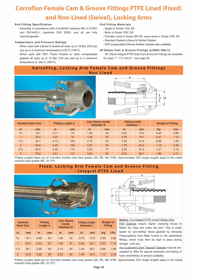
End Fitting Specification - Generally in accordance with A-A-59326 (replaces MIL-C-27487)
and EN14420-1 (replaces DIN 2828), and all are fully interchangeable.
Temperature and Pressure Ratings - When used with a Buna N Gasket all sizes up to 16 Bar (230 psi)
and up to a maximum temperature of 65˚C (149˚F). - When used with FEP, Fluoro Rubber or other encapsulated
gaskets all sizes up to 10 Bar (145 psi) and up to a maximum temperature of 204˚C (400˚F).
End Fitting Materials - Spigot in Grade 316L SS - Body in Grade 316C SS - Ferrules, most in Grade 304 SS, some sizes in Grade 316L SS - Standard Gasket is Buna N (Nitrile) Rubber. - FEP encapsulated Silicone Rubber Gaskets also available.
90˚Elbow Cam & Groove Fittings (LINED ONLY) - 90˚ Elbow Integral PTFE lined Cam & Groove Fittings are available for sizes 1”, 11/2” and 2” - see page 29.
Nominal Hose Size *Fitting Length A Cam Sleeve Inside Diameter D
Fitting Inside Diameter I Weight of Fitting
1 25.4 3.07 78 1.46 37 0.75 19.1 0.51 1.1211/2 38.1 4.13 105 2.13 54 1.25 31.8 0.88 1.94
21/2 63.5 4.49 114 3.03 77 2.25 57.2 1.41 3.103 76.2 4.61 117 3.62 92 2.63 66.7 1.89 4.17
3/4 19.1 3.11 79 1.26 32 0.63 15.9 0.40 0.88in mm in mm in mm in mm Kg Lbs
*Fitting Lengths listed are for Corroflon braided only hose grades (SS, PB, HB, KYB). Approximately 33% longer lengths apply to the rubber covered hose grades (RC, SI, FP).
*Fitting Lengths listed are for Corroflon braided only hose grades (SS, PB, HB, KYB). Approximately 33% longer lengths apply to the rubber covered hose grades (RC, SI, FP).
2 50.8 4.25 108 2.52 64 1.75 44.5 1.15 2.53
Notes: For Integral PTFE Lined Fittings Only FEP Gaskets require higher clamping forces to flatten the Seal and make the joint. This is made easier by “pre-setting” these gaskets by clamping Polypropylene Cam Male Inserts to the assembled fittings, which must then be kept in place during storage, until use.Any Customer’s Own “Special” Gaskets must be pre-supplied to Aflex for special assembly and testing of hose assemblies, to ensure suitability.
3/4 19.1 2.48 63 1.26 32 0.70 17.8 0.39 0.86
in mm in mm in mm in mm Kg
1 25.4 2.40 61 1.46 37 0.95 24.1 0.50 1.10
11/2 38.1 2.56 65 2.13 54 1.44 36.7 0.86 1.89
2 50.8 2.56 65 2.52 64 1.94 49.3 1.10 2.42
Nominal Hose Size
*Fitting Length A
Cam Sleeve Inside
Diameter D
Fitting Inside Diameter I
Weight of Fitting
Lbs
2 50 3.63 92 43/8 118 1.69 43 3.359 7.40
Page 19
Corroflon Male Cam & Groove Fittings, PTFE Lined & Non-
Lined and Flange Adaptors, PTFE Lined
*Fitting Lengths listed are for Corroflon braided only hose grades (SS, PB, HB, KYB). Approximately 33% longer lengths apply to the rubber covered hose grades (RC, SI, FP).
P T F E L i n e d o r N o n - L i n e d M a l e C a m a n d G r o o v e F i t t i n g s
I n t e g r a l P T F E L i n e d C a m & G r o o v e
M a l e F i t t i n g
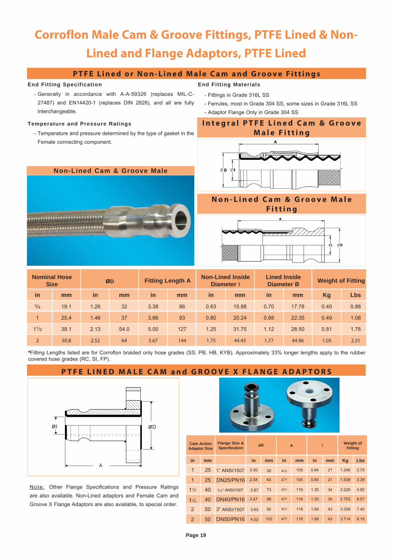
End Fitting Specification
- Generally in accordance with A-A-59326 (replaces MIL-C-27487) and EN14420-1 (replaces DIN 2828), and all are fully interchangeable.
Temperature and Pressure Ratings
- Temperature and pressure determined by the type of gasket in the Female connecting component.
End Fitting Materials
- Fittings in Grade 316L SS - Ferrules, most in Grade 304 SS, some sizes in Grade 316L SS - Adaptor Flange Only in Grade 304 SS
P T F E L I N E D M A L E C A M a n d G R O O V E X F L A N G E A D A P T O R S
Nominal Hose Size øD Fitting Length A Non-Lined Inside
Diameter ILined Inside Diameter B Weight of Fitting
in mm in mm in mm in mm in mm Kg Lbs3/4 19.1 1.26 32 3.38 86 0.63 15.88 0.70 17.78 0.40 0.88
1 25.4 1.46 37 3.66 93 0.80 20.24 0.88 22.35 0.49 1.08
11/2 38.1 2.13 54.0 5.00 127 1.25 31.75 1.12 28.50 0.81 1.78
2 50.8 2.52 64 5.67 144 1.75 44.45 1.77 44.96 1.05 2.31
Note: Other Flange Specifications and Pressure Ratings are also available. Non-Lined adaptors and Female Cam and Groove X Flange Adaptors are also available, to special order.
øDøI
A
N o n - L i n e d C a m & G r o o v e M a l e
F i t t i n g
Non-Lined Cam & Groove Male
in mm in mm in mm in mm Kg Lbs
1 25 2.00 50 41/8 105 0.84 21 1.246 2.75
1 25 2.58 64 41/8 105 0.84 21 1.538 3.39
11/2 40 2.87 73 43/8 118 1.35 34 2.228 4.92
11/2 40 3.47 88 43/8 118 1.35 34 2.753 6.07
2 50 4.02 102 43/8 118 1.69 43 3.714 8.19
Cam ActionAdaptor Size
øD A I Weight of Fitting
DN25/PN16
11/2” ANSI/1507
DN40/PN16
2” ANSI/1507
DN50/PN16
1” ANSI/1507
Flange Size & Specification
Page 20
Corroflon Mini-Sanitary and Sanitary Triclover Fittings -
PTFE Lined
*Fitting Lengths listed are for Corroflon braided only hose grades (SS, PB, HB, KYB). Approximately 33% longer lengths apply to the rubber covered hose grades (RC, SI, FP).
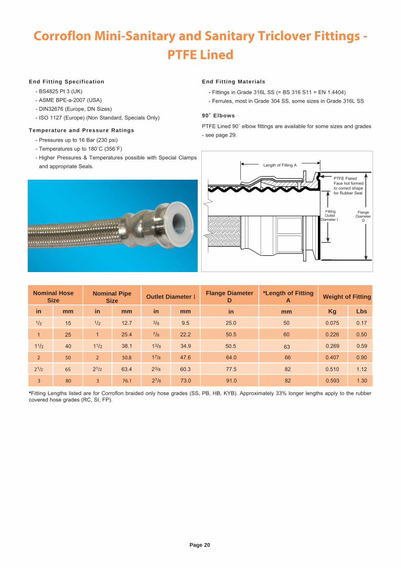
Length of Fitting A
Fitting Outlet
Diameter II
PTFE Flared Face hot formed to correct shape for Rubber Seal
Flange Diameter
D
End Fitting Specification
- BS4825 Pt 3 (UK) - ASME BPE-a-2007 (USA) - DIN32676 (Europe, DN Sizes) - ISO 1127 (Europe) (Non Standard, Specials Only)
Temperature and Pressure Ratings
- Pressures up to 16 Bar (230 psi) - Temperatures up to 180˚C (356˚F) - Higher Pressures & Temperatures possible with Special Clamps
and appropriate Seals.
End Fitting Materials
- Fittings in Grade 316L SS (= BS 316 S11 = EN 1.4404) - Ferrules, most in Grade 304 SS, some sizes in Grade 316L SS
90˚ Elbows
PTFE Lined 90˚ elbow fittings are available for some sizes and grades - see page 29.
11/2 40 11/2 38.1 13/8 34.9 0.269 0.59
Nominal Hose Size
Nominal Pipe Size Outlet Diameter I Flange Diameter
D*Length of Fitting
A Weight of Fitting
in mm in mm in mm Kg Lbs1/2 15 1/2 12.7 3/8 9.5 0.075 0.17
1 25 1 25.4 7/8 22.2 0.226 0.50
2 50 2 50.8 17/8 47.6 0.407 0.90
21/2 65 21/2 63.4 23/8 60.3 0.510 1.12
3 80 3 76.1 27/8 73.0 0.593 1.30
50.5 60
25.0 50
in mm
64.0 66
77.5 82
91.0 82
50.5 63
Page 21
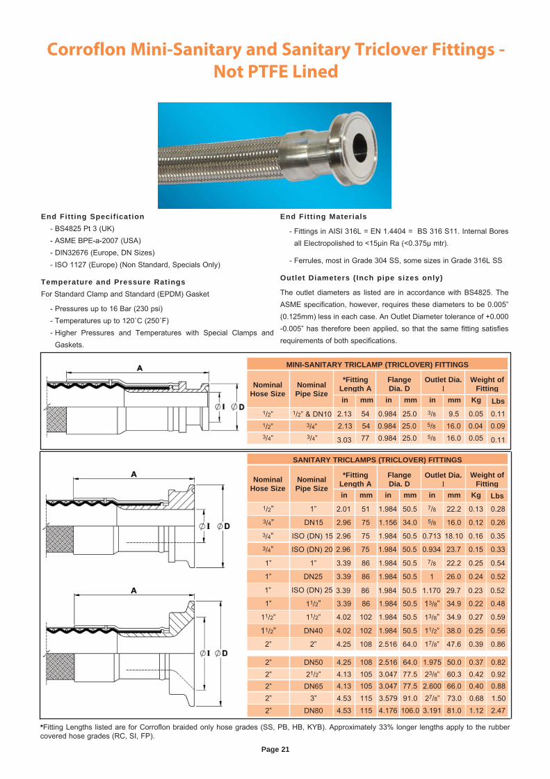
Corroflon Mini-Sanitary and Sanitary Triclover Fittings -
Not PTFE Lined
End Fitting Specification - BS4825 Pt 3 (UK) - ASME BPE-a-2007 (USA) - DIN32676 (Europe, DN Sizes) - ISO 1127 (Europe) (Non Standard, Specials Only)
Temperature and Pressure RatingsFor Standard Clamp and Standard (EPDM) Gasket
- Pressures up to 16 Bar (230 psi) - Temperatures up to 120˚C (250˚F) - Higher Pressures and Temperatures with Special Clamps and
Gaskets.
End Fitting Materials
- Fittings in AISI 316L = EN 1.4404 = BS 316 S11. Internal Bores all Electropolished to <15μin Ra (<0.375μ mtr).
- Ferrules, most in Grade 304 SS, some sizes in Grade 316L SS
Outlet Diameters (Inch pipe sizes only)
The outlet diameters as listed are in accordance with BS4825. The ASME specification, however, requires these diameters to be 0.005” (0.125mm) less in each case. An Outlet Diameter tolerance of +0.000 -0.005” has therefore been applied, so that the same fitting satisfies requirements of both specifications.
*Fitting Lengths listed are for Corroflon braided only hose grades (SS, PB, HB, KYB). Approximately 33% longer lengths apply to the rubber covered hose grades (RC, SI, FP).
SANITARY TRICLAMPS (TRICLOVER) FITTINGS
Nominal Hose Size
Nominal Pipe Size
*Fitting Length A
Flange Dia. D
Outlet Dia. I
Weight of Fitting
in mm in mm in mm Kg
2.96 75 1.156 34.0 5/8 16.0 0.12 0.26
3.39 86 1.984 50.5 7/8 22.2 0.25 0.54
3.39 86 1.984 50.5 1 26.0 0.24 0.52
3.39 86 1.984 50.5 1.170 29.7 0.23 0.52
3.39 86 1.984 50.5 13/8” 34.9 0.22 0.48
4.02 102 1.984 50.5 13/8” 34.9 0.27 0.59
4.02 102 1.984 50.5 11/2” 38.0 0.25 0.56
4.25 108 2.516 64.0 17/8” 47.6 0.39 0.86
2.96 75 1.984 50.5 0.713 18.10 0.16 0.35
2.96 75 1.984 50.5 0.934 23.7 0.15 0.33
2.01 51 1.984 50.5 7/8 22.2 0.13 0.28
4.25 108 2.516 64.0 1.975 50.0 0.37 0.824.13 105 3.047 77.5 23/8” 60.3 0.42 0.924.13 105 3.047 77.5 2.600 66.0 0.40 0.884.53 115 3.579 91.0 27/8” 73.0 0.68 1.504.53 115 4.176 106.0 3.191 81.0 1.12 2.47
1” 1”
1” DN25
1” ISO (DN) 25
1” 11/2”11/2” 11/2”
11/2” DN40
2” 2”
3/4” DN153/4” ISO (DN) 153/4” ISO (DN) 20
1/2” 1”
2” 21/2”2” DN652” 3”
2” DN80
2” DN50
MINI-SANITARY TRICLAMP (TRICLOVER) FITTINGS
Nominal Hose Size
Nominal Pipe Size
*Fitting Length A
Flange Dia. D
Outlet Dia. I
Weight of Fitting
3/4” 3/4”
in mm in mm in mm Kg
3.03 77 0.984 25.0 5/8 16.0 0.05 0.11
1/2” 3/4” 2.13 54 0.984 25.0 5/8 16.0 0.04 0.09 2.13 54 0.984 25.0 3/8 9.5 0.05 0.111/2” 1/2” & DN10
Lbs
Lbs
Page 22
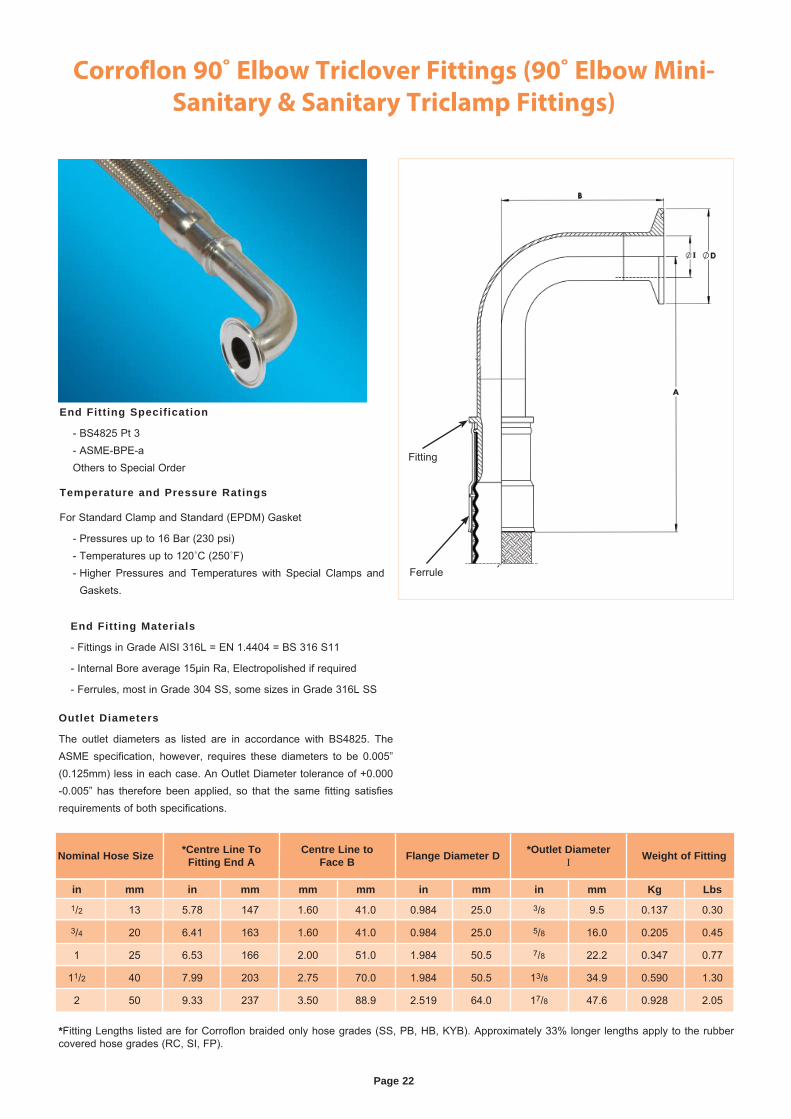
Corroflon 90˚ Elbow Triclover Fittings (90˚ Elbow Mini-
Sanitary & Sanitary Triclamp Fittings)
End Fitting Specification
- BS4825 Pt 3 - ASME-BPE-a Others to Special Order
Temperature and Pressure Ratings
For Standard Clamp and Standard (EPDM) Gasket
- Pressures up to 16 Bar (230 psi) - Temperatures up to 120˚C (250˚F) - Higher Pressures and Temperatures with Special Clamps and
Gaskets.
*Fitting Lengths listed are for Corroflon braided only hose grades (SS, PB, HB, KYB). Approximately 33% longer lengths apply to the rubber covered hose grades (RC, SI, FP).
End Fitting Materials
- Fittings in Grade AISI 316L = EN 1.4404 = BS 316 S11
- Internal Bore average 15μin Ra, Electropolished if required
- Ferrules, most in Grade 304 SS, some sizes in Grade 316L SS
Outlet Diameters
The outlet diameters as listed are in accordance with BS4825. The ASME specification, however, requires these diameters to be 0.005” (0.125mm) less in each case. An Outlet Diameter tolerance of +0.000 -0.005” has therefore been applied, so that the same fitting satisfies requirements of both specifications.
Nominal Hose Size *Centre Line To Fitting End A
Centre Line to Face B Flange Diameter D *Outlet Diameter
I Weight of Fitting
in mm in mm mm mm in mm in mm Kg Lbs1/2 13 5.78 147 1.60 41.0 0.984 25.0 3/8 9.5 0.137 0.30
3/4 20 6.41 163 1.60 41.0 0.984 25.0 5/8 16.0 0.205 0.45
1 25 6.53 166 2.00 51.0 1.984 50.5 7/8 22.2 0.347 0.77
11/2 40 7.99 203 2.75 70.0 1.984 50.5 13/8 34.9 0.590 1.30
2 50 9.33 237 3.50 88.9 2.519 64.0 17/8 47.6 0.928 2.05
Ferrule
Fitting
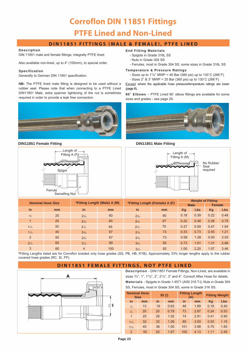
Corroflon DIN 11851 Fittings
PTFE Lined and Non-Lined
Length of Fitting A (F)
Spigot
FerruleSwivelling Nut
DIN11851 Female Fitting
Length of Fitting A (M)
No Rubber Seal required
DIN11851 Male Fitting
DescriptionDIN 11851 male and female fittings, integrally PTFE lined.
Also available non-lined, up to 4” (100mm), to special order.
SpecificationGenerally to German DIN 11851 specification.
NB: The PTFE lined male fitting is designed to be used without a rubber seal. Please note that when connecting to a PTFE Lined DIN11851 Male, extra spanner tightening of the nut is sometimes required in order to provide a leak free connection.
Description - DIN11851 Female Fittings, Non-Lined, are available in sizes 3/4”, 1”, 11/2”, 2”, 21/2”, 3” and 4”. Consult Aflex Hose for details.Materials - Spigots in Grade 1.4571 (AISI 316 Ti), Nuts in Grade 304 SS, Ferrules, most in Grade 304 SS, some in Grade 316 SS.
End Fitting Materials - Spigots in Grade 316L SS - Nuts in Grade 304 SS - Ferrules, most in Grade 304 SS, some sizes in Grade 316L SS
Temperature & Pressure Ratings - Sizes up to 11/2” MWP = 40 Bar (580 psi) up to 130˚C (266˚F) - Sizes 2” & 3” MWP = 25 Bar (360 psi) up to 130˚C (266˚F)Except where the applicable hose pressure/temperature ratings are lower (page 8).
90˚ Elbows - PTFE Lined 90˚ elbow fittings are available for some sizes and grades - see page 29.
*Fitting Lengths listed are for Corroflon braided only hose grades (SS, PB, HB, KYB). Approximately 33% longer lengths apply to the rubber covered hose grades (RC, SI, FP).
D I N 1 1 8 5 1 F I T T I N G S ( M A L E & F E M A L E ) , P T F E L I N E D
D I N 1 1 8 5 1 F E M A L E F I T T I N G S , N O T P T F E L I N E D
Page 23
Nominal Hose Size ID (I) Fitting Length
(A) Fitting Weight
in mm in mm in mm Kg Lbs1/2 13 16 0.63 48 1.89 0.18 0.403/4 20 20 0.79 73 2.87 0.24 0.531 25 26 1.02 74 2.91 0.41 0.90
11/4 32 32 1.26 89 3.50 0.52 1.1511/2 40 38 1.50 101 3.98 0.75 1.652 50 50 1.97 105 4.13 1.11 2.45
in mm in mm in mm3/4 20 23/8 60 23/8 601 25 23/8 60 25/8 67
11/4 32 21/2 65 23/4 70
11/2 40 25/8 67 27/8 732 50 25/8 67 27/8 73
21/2 65 31/2 89 35/8 923 80 4 100 35/8 92
Nominal Hose Size *Fitting Length (Male) A (M) *Fitting Length (Female) A (F) Weight of FittingMale Female
Kg Lbs Kg Lbs0.18 0.39 0.22 0.48
0.22 0.48 0.36 0.79
0.27 0.59 0.47 1.040.33 0.73 0.55 1.210.58 1.28 0.93 2.05
0.73 1.61 1.31 2.88
1.00 2.20 1.57 3.46
Page 24
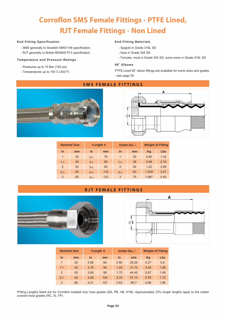
Corroflon SMS Female Fittings - PTFE Lined,
RJT Female Fittings - Non Lined
*Fitting Lengths listed are for Corroflon braided only hose grades (SS, PB, HB, KYB). Approximately 33% longer lengths apply to the rubber covered hose grades (RC, SI, FP).
S M S F E M A L E F I T T I N G S
R J T F E M A L E F I T T I N G S
End Fitting Specification
- SMS generally to Swedish SMS1148 specification. - RJT generally to British BS4825 Pt 5 specification.
Temperature and Pressure Ratings
- Pressures up to 10 Bar (150 psi) - Temperatures up to 150˚C (302˚F)
End Fitting Materials
- Spigots in Grade 316L SS - Nuts in Grade 304 SS - Ferrules, most in Grade 304 SS, some sizes in Grade 316L SS
90˚ Elbows
PTFE Lined 90˚ elbow fittings are available for some sizes and grades - see page 29.
in mm in mm in mm Kg Lbs1 25 31/8 79 1 25 0.60 1.32
11/2 40 31/2 89 11/2 38 0.98 2.162 50 33/4 95 2 50 1.22 2.69
21/2 65 45/8 116 21/2 63 1.549 3.41
3 80 43/4 122 3 75 1.997 4.40
Nominal Size *Length A Outlet Dia. I Weight of Fitting
in mm in mm in mm Kg Lbs1 25 2.68 68 0.80 20.24 0.27 0.6
11/2 40 3.78 96 1.25 31.75 0.49 1.082 50 3.90 99 1.75 44.45 0.67 1.48
21/2 65 4.09 104 2.25 57.15 0.78 1.72
3 80 4.21 107 2.63 66.7 0.89 1.96
Nominal Size *Length A Outlet Dia. I Weight of Fitting
Page 25
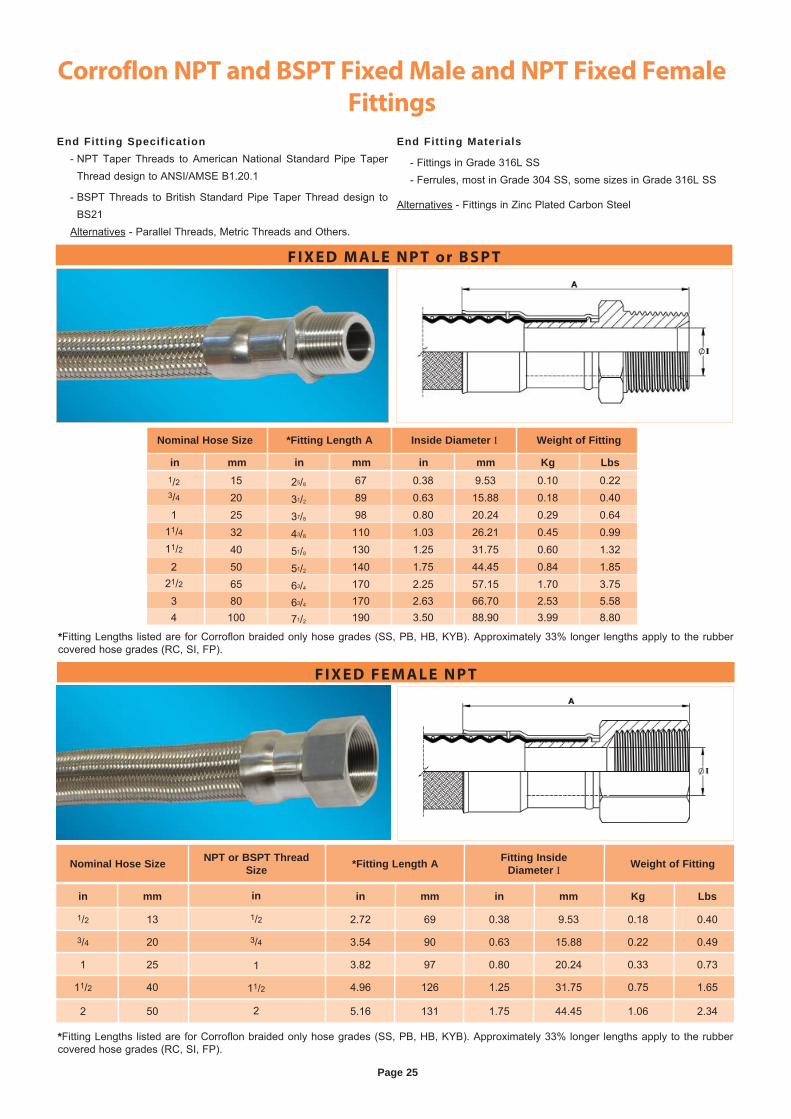
Corroflon NPT and BSPT Fixed Male and NPT Fixed Female
Fittings
F I X E D M A L E N P T or B S P T
F I X E D F E M A L E N P T
End Fitting Specification - NPT Taper Threads to American National Standard Pipe Taper
Thread design to ANSI/AMSE B1.20.1
- BSPT Threads to British Standard Pipe Taper Thread design to BS21
Alternatives - Parallel Threads, Metric Threads and Others.
End Fitting Materials
- Fittings in Grade 316L SS - Ferrules, most in Grade 304 SS, some sizes in Grade 316L SS
Alternatives - Fittings in Zinc Plated Carbon Steel
Nominal Hose Size NPT or BSPT Thread Size *Fitting Length A Fitting Inside
Diameter I Weight of Fitting
in mm in mm in mm Kg Lbs
1/2 13 2.72 69 0.38 9.53 0.18 0.40
3/4 20 3.54 90 0.63 15.88 0.22 0.49
1 25 3.82 97 0.80 20.24 0.33 0.73
11/2 40 4.96 126 1.25 31.75 0.75 1.65
2 50 5.16 131 1.75 44.45 1.06 2.34
in
1/2
3/4
1
11/2
2
in mm in mm in mm Kg Lbs1/2 15 25/8 67 0.38 9.53 0.10 0.223/4 20 31/2 89 0.63 15.88 0.18 0.401 25 37/8 98 0.80 20.24 0.29 0.64
11/4 32 43/8 110 1.03 26.21 0.45 0.9911/2 40 51/8 130 1.25 31.75 0.60 1.322 50 51/2 140 1.75 44.45 0.84 1.85
21/2 65 63/4 170 2.25 57.15 1.70 3.753 80 63/4 170 2.63 66.70 2.53 5.584 100 71/2 190 3.50 88.90 3.99 8.80
Nominal Hose Size *Fitting Length A Inside Diameter I Weight of Fitting
*Fitting Lengths listed are for Corroflon braided only hose grades (SS, PB, HB, KYB). Approximately 33% longer lengths apply to the rubber covered hose grades (RC, SI, FP).
*Fitting Lengths listed are for Corroflon braided only hose grades (SS, PB, HB, KYB). Approximately 33% longer lengths apply to the rubber covered hose grades (RC, SI, FP).
Page 26
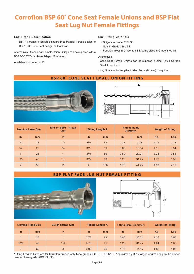
*Fitting Lengths listed are for Corroflon braided only hose grades (SS, PB, HB, KYB). Approximately 33% longer lengths apply to the rubber covered hose grades (RC, SI, FP).
Corroflon BSP 60˚ Cone Seat Female Unions and BSP Flat
Seat Lug Nut Female Fittings
End Fitting Specification
- BSPP Threads to British Standard Pipe Parallel Thread design to BS21, 60˚ Cone Seat design, or Flat Seat.
Alternatives - Cone Seat Female Union Fittings can be supplied with a BSPP/BSPT Taper Male Adaptor if required.
Available in sizes up to 4”
End Fitting Materials
- Spigots in Grade 316L SS - Nuts in Grade 316L SS - Ferrules, most in Grade 304 SS, some sizes in Grade 316L SS
Alternatives - Cone Seat Female Unions can be supplied in Zinc Plated Carbon
Steel if required.
- Lug Nuts can be supplied in Gun Metal (Bronze) if required.
Nominal Hose Size BSPP Thread Size *Fitting Length A Fitting Bore Diameter I Weight of Fitting
in mm in mm in mm Kg Lbs
11/2 40 3.78 96 1.25 31.75 0.61 1.33
2 50 3.90 99 1.75 44.45 0.88 1.95
1 25 2.72 69 0.80 20.24 0.25 0.55
in
1
11/2
2
B S P F L A T F A C E L U G N U T F E M A L E F I T T I N G
B S P 60˚ C O N E S E A T F E M A L E U N I O N F I T T I N G
in mm in mm in mm Kg Lbs
1/2 13 21/2 63 0.37 9.35 0.11 0.25
3/4 20 31/2 89 0.63 15.88 0.15 0.34
1 25 31/2 89 0.80 20.24 0.24 0.53
11/2 40 37/8 98 1.25 31.75 0.72 1.59
2 50 4 100 1.75 44.45 0.99 2.19
in
1/2
3/4
1
11/2
2
Nominal Hose Size NPT or BSPT Thread Size *Fitting Length A Fitting Inside
Diameter I Weight of Fitting
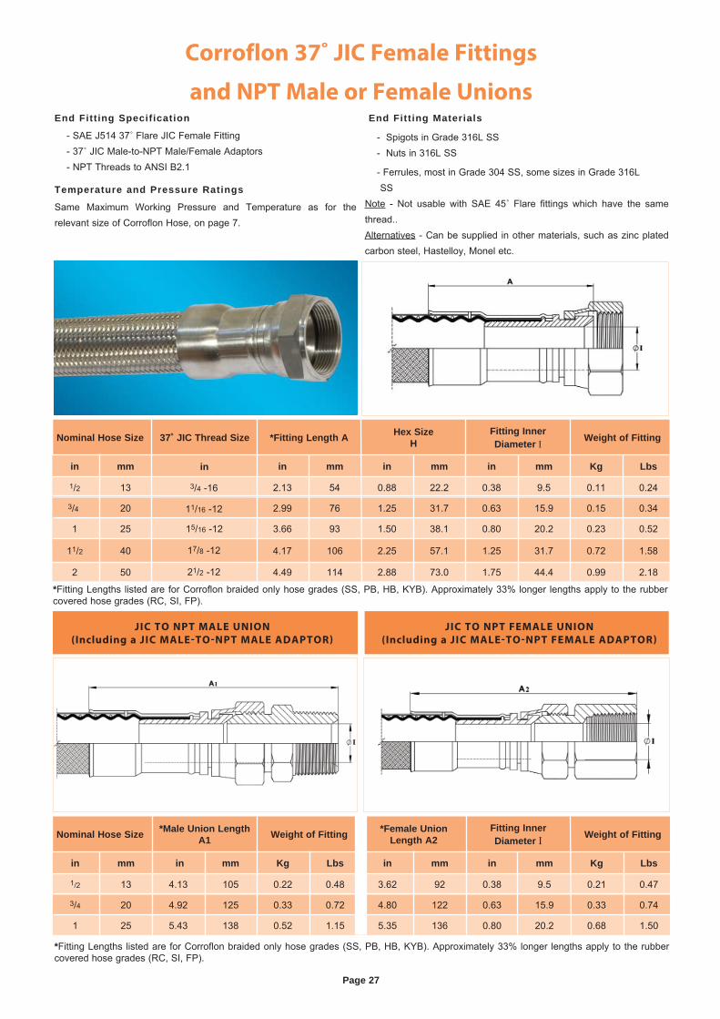
Corroflon 37˚ JIC Female Fittings
and NPT Male or Female UnionsEnd Fitting Specification
- SAE J514 37˚ Flare JIC Female Fitting - 37˚ JIC Male-to-NPT Male/Female Adaptors - NPT Threads to ANSI B2.1
Temperature and Pressure Ratings
Same Maximum Working Pressure and Temperature as for the relevant size of Corroflon Hose, on page 7.
End Fitting Materials
- Spigots in Grade 316L SS - Nuts in 316L SS
- Ferrules, most in Grade 304 SS, some sizes in Grade 316L SS
Note - Not usable with SAE 45˚ Flare fittings which have the same thread..Alternatives - Can be supplied in other materials, such as zinc plated carbon steel, Hastelloy, Monel etc.
JIC TO NPT MALE UNION
(Including a JIC MALE-TO-NPT MALE ADAPTOR)
JIC TO NPT FEMALE UNION
(Including a JIC MALE-TO-NPT FEMALE ADAPTOR)
Nominal Hose Size *Male Union Length A1 Weight of Fitting *Female Union
Length A2Fitting InnerDiameter I Weight of Fitting
3/4 20 4.92 125 0.33 0.72 4.80 122 0.63 15.9 0.33 0.74
1 25 5.43 138 0.52 1.15 5.35 136 0.80 20.2 0.68 1.50
in mm in mm Kg Lbs in mm in mm Kg Lbs
1/2 13 4.13 105 0.22 0.48 3.62 92 0.38 9.5 0.21 0.47
Nominal Hose Size 37˚ JIC Thread Size *Fitting Length A Hex SizeH
Fitting InnerDiameter I Weight of Fitting
3/4 20 2.99 76 1.25 31.7 0.63 15.9 0.15 0.34
1 25 3.66 93 1.50 38.1 0.80 20.2 0.23 0.52
11/2 40 4.17 106 2.25 57.1 1.25 31.7 0.72 1.58
2 50 4.49 114 2.88 73.0 1.75 44.4 0.99 2.18
in mm in mm in mm in mm Kg Lbs
1/2 13 2.13 54 0.88 22.2 0.38 9.5 0.11 0.24
in
15/16 -12
21/2 -12
17/8 -12
11/16 -12
3/4 -16
*Fitting Lengths listed are for Corroflon braided only hose grades (SS, PB, HB, KYB). Approximately 33% longer lengths apply to the rubber covered hose grades (RC, SI, FP).
*Fitting Lengths listed are for Corroflon braided only hose grades (SS, PB, HB, KYB). Approximately 33% longer lengths apply to the rubber covered hose grades (RC, SI, FP).
Page 27
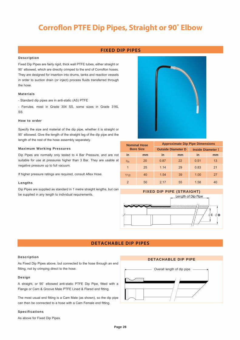
Corroflon PTFE Dip Pipes, Straight or 90˚ Elbow
FIXED DIP PIPES
DETACHABLE DIP PIPES
Description
Fixed Dip Pipes are fairly rigid, thick wall PTFE tubes, either straight or 90˚ elbowed, which are directly crimped to the end of Corroflon hoses. They are designed for insertion into drums, tanks and reaction vessels in order to suction drain (or inject) process fluids transferred through the hose.
Materials
- Standard dip pipes are in anti-static (AS) PTFE
- Ferrules, most in Grade 304 SS, some sizes in Grade 316L SS
How to order
Specify the size and material of the dip pipe, whether it is straight or 90˚ elbowed. Give the length of the straight leg of the dip pipe and the length of the rest of the hose assembly separately.
Maximum Working Pressures
Dip Pipes are normally only tested to 4 Bar Pressure, and are not suitable for use at pressures higher than 3 Bar. They are usable at negative pressure up to full vacuum.
If higher pressure ratings are required, consult Aflex Hose.
Lengths
Dip Pipes are supplied as standard in 1 metre straight lengths, but can be supplied in any length to individual requirements.
Description
As Fixed Dip Pipes above, but connected to the hose through an end fitting, not by crimping direct to the hose.
Design
A straight, or 90˚ elbowed anti-static PTFE Dip Pipe, fitted with a Flange or Cam & Groove Male PTFE Lined & Flared end fitting.
The most usual end fitting is a Cam Male (as shown), so the dip pipe can then be connected to a hose with a Cam Female end fitting.
Specifications
As above for Fixed Dip Pipes.
Overall length of dip pipe
DETACHABLE DIP PIPE
FIXED DIP PIPE (STRAIGHT)
in mm in mm in mm
Nominal HoseBore Size Outside Diameter D Inside Diameter I
Approximate Dip Pipe Dimensions
3/4 20 0.87 22 0.51 13
1 25 1.14 29 0.83 21
11/2 40 1.54 39 1.00 27
2 50 2.17 55 1.58 40
Page 28
Corroflon 90˚ Elbow Fittings,
PTFE Lined and Non-Lined
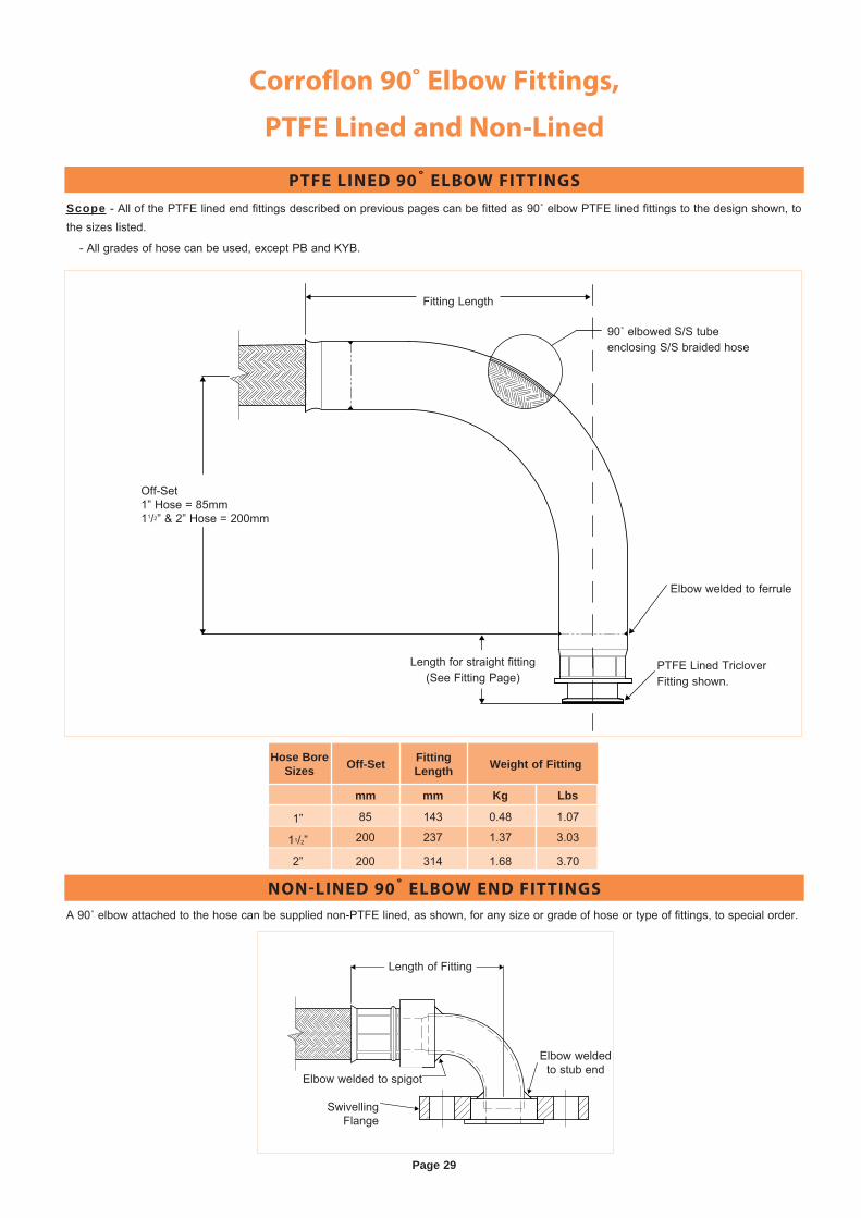
Scope - All of the PTFE lined end fittings described on previous pages can be fitted as 90˚ elbow PTFE lined fittings to the design shown, to the sizes listed.
- All grades of hose can be used, except PB and KYB.
A 90˚ elbow attached to the hose can be supplied non-PTFE lined, as shown, for any size or grade of hose or type of fittings, to special order.
PTFE LINED 90˚ ELBOW FITTINGS
NON-LINED 90˚ ELBOW END FITTINGS
90˚ elbowed S/S tube enclosing S/S braided hose
Fitting Length
Length for straight fitting (See Fitting Page)
Elbow welded to ferrule
PTFE Lined Triclover Fitting shown.
Off-Set1” Hose = 85mm11/2” & 2” Hose = 200mm
Length of Fitting
Elbow welded to stub end
Elbow welded to spigot
Swivelling Flange
Page 29
Off-Set Fitting Length Weight of Fitting
mm mm Kg Lbs
1” 85 143 0.48 1.07
11/2” 200 237 1.37 3.03
2” 200 314 1.68 3.70
Hose Bore Sizes
Page 30
Corroflon Steam Heated
Hose Assemblies. (CH Grade)
Purpose
For use in applications where the temperature of the process fluid entering the hose assembly must be maintained as it passes through the hose. This is usually required to prevent solidification or an increase in the fluid viscosity. Steam or hot oil heating is preferred to electrical heating in some applications for reasons of availability or safety, but is less controllable.
Description
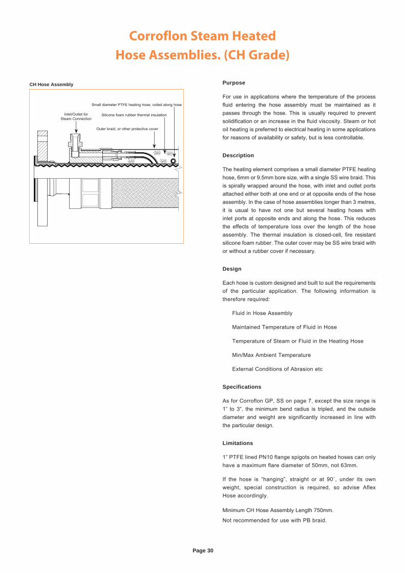
The heating element comprises a small diameter PTFE heating hose, 6mm or 9.5mm bore size, with a single SS wire braid. This is spirally wrapped around the hose, with inlet and outlet ports attached either both at one end or at opposite ends of the hose assembly. In the case of hose assemblies longer than 3 metres, it is usual to have not one but several heating hoses with inlet ports at opposite ends and along the hose. This reduces the effects of temperature loss over the length of the hose assembly. The thermal insulation is closed-cell, fire resistant silicone foam rubber. The outer cover may be SS wire braid with or without a rubber cover if necessary.
Design
Each hose is custom designed and built to suit the requirements of the particular application. The following information is therefore required:
Fluid in Hose Assembly
Maintained Temperature of Fluid in Hose
Temperature of Steam or Fluid in the Heating Hose
Min/Max Ambient Temperature
External Conditions of Abrasion etc
Specifications
As for Corroflon GP, SS on page 7, except the size range is1” to 3”, the minimum bend radius is tripled, and the outside diameter and weight are significantly increased in line with the particular design.
Limitations
1” PTFE lined PN10 flange spigots on heated hoses can only have a maximum flare diameter of 50mm, not 63mm.
If the hose is “hanging”, straight or at 90˚, under its own weight, special construction is required, so advise Aflex Hose accordingly.
Minimum CH Hose Assembly Length 750mm.
Not recommended for use with PB braid.
Inlet/Outlet for Steam Connection
Small diameter PTFE heating hose, coiled along hose
Silicone foam rubber thermal insulation
Outer braid, or other protective cover
CH Hose Assembly
Page 31
Corroflon Electrically Trace Heated
Hose Assemblies. (ETH Grade)
PurposeFor use in applications where the temperature of the process fluid entering the hose assembly must be regulated as it passes through the hose. This is usually required to prevent solidification or an increase in the fluid viscosity. In some applications, an additional ‘heating up’ or ‘melting’ facility is also required. Electrical heating is often preferred to steam heating because it is more convenient, more controllable and usually more readily available. ‘Zone 1 Hazardous Area’ requirements can be met.
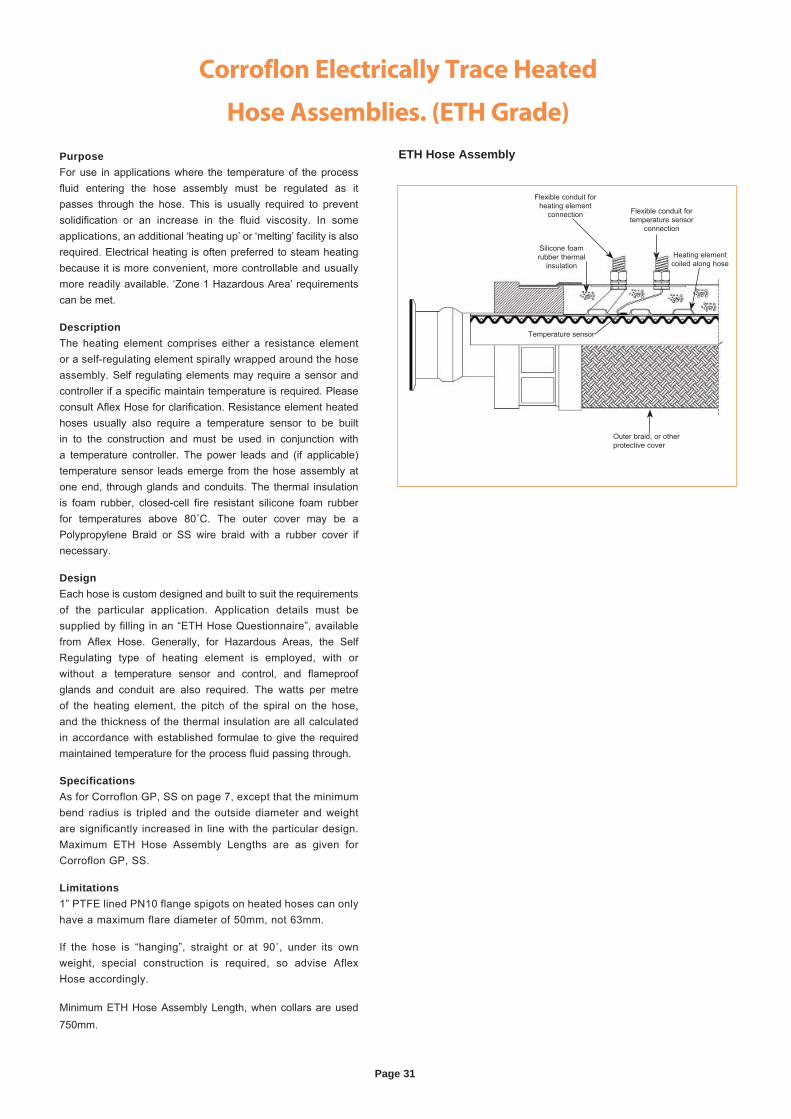
DescriptionThe heating element comprises either a resistance element or a self-regulating element spirally wrapped around the hose assembly. Self regulating elements may require a sensor and controller if a specific maintain temperature is required. Please consult Aflex Hose for clarification. Resistance element heated hoses usually also require a temperature sensor to be built in to the construction and must be used in conjunction with a temperature controller. The power leads and (if applicable) temperature sensor leads emerge from the hose assembly at one end, through glands and conduits. The thermal insulation is foam rubber, closed-cell fire resistant silicone foam rubber for temperatures above 80˚C. The outer cover may be a Polypropylene Braid or SS wire braid with a rubber cover if necessary.
DesignEach hose is custom designed and built to suit the requirements of the particular application. Application details must besupplied by filling in an “ETH Hose Questionnaire”, available from Aflex Hose. Generally, for Hazardous Areas, the Self Regulating type of heating element is employed, with or without a temperature sensor and control, and flameproof glands and conduit are also required. The watts per metre of the heating element, the pitch of the spiral on the hose, and the thickness of the thermal insulation are all calculated in accordance with established formulae to give the required maintained temperature for the process fluid passing through.
SpecificationsAs for Corroflon GP, SS on page 7, except that the minimum bend radius is tripled and the outside diameter and weight are significantly increased in line with the particular design. Maximum ETH Hose Assembly Lengths are as given for Corroflon GP, SS.
Limitations1” PTFE lined PN10 flange spigots on heated hoses can only have a maximum flare diameter of 50mm, not 63mm.
If the hose is “hanging”, straight or at 90˚, under its own weight, special construction is required, so advise Aflex Hose accordingly.
Minimum ETH Hose Assembly Length, when collars are used 750mm.
ETH Hose Assembly
Flexible conduit for temperature sensor
connection
Heating element coiled along hose
Temperature sensor
Outer braid, or other protective cover
Silicone foam rubber thermal
insulation
Flexible conduit for heating element
connection
Page 32
Corroflon Standard and Puretag Labelling and Colour
Coding Systems
Standard Labelling
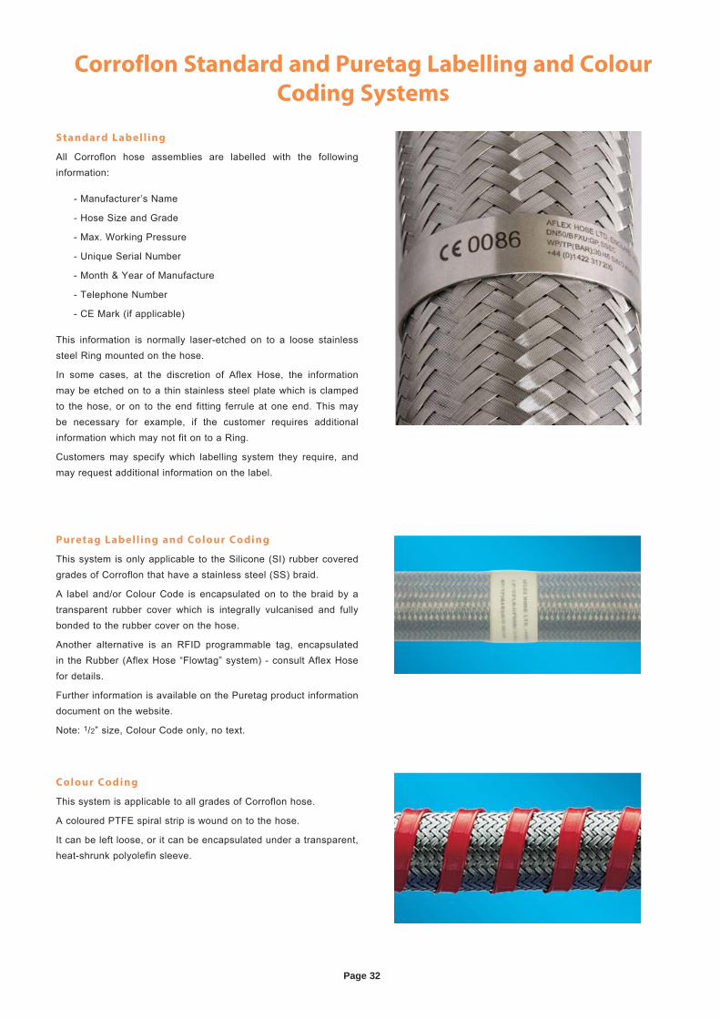
All Corroflon hose assemblies are labelled with the following information:
- Manufacturer’s Name
- Hose Size and Grade
- Max. Working Pressure
- Unique Serial Number
- Month & Year of Manufacture
- Telephone Number
- CE Mark (if applicable)
This information is normally laser-etched on to a loose stainless steel Ring mounted on the hose.
In some cases, at the discretion of Aflex Hose, the information may be etched on to a thin stainless steel plate which is clamped to the hose, or on to the end fitting ferrule at one end. This may be necessary for example, if the customer requires additional information which may not fit on to a Ring.
Customers may specify which labelling system they require, and may request additional information on the label.
Puretag Labelling and Colour Coding
This system is only applicable to the Silicone (SI) rubber covered grades of Corroflon that have a stainless steel (SS) braid.
A label and/or Colour Code is encapsulated on to the braid by a transparent rubber cover which is integrally vulcanised and fully bonded to the rubber cover on the hose.
Another alternative is an RFID programmable tag, encapsulated in the Rubber (Aflex Hose “Flowtag” system) - consult Aflex Hose for details.
Further information is available on the Puretag product information document on the website.
Note: 1/2” size, Colour Code only, no text.
Colour Coding
This system is applicable to all grades of Corroflon hose.
A coloured PTFE spiral strip is wound on to the hose.
It can be left loose, or it can be encapsulated under a transparent, heat-shrunk polyolefin sleeve.
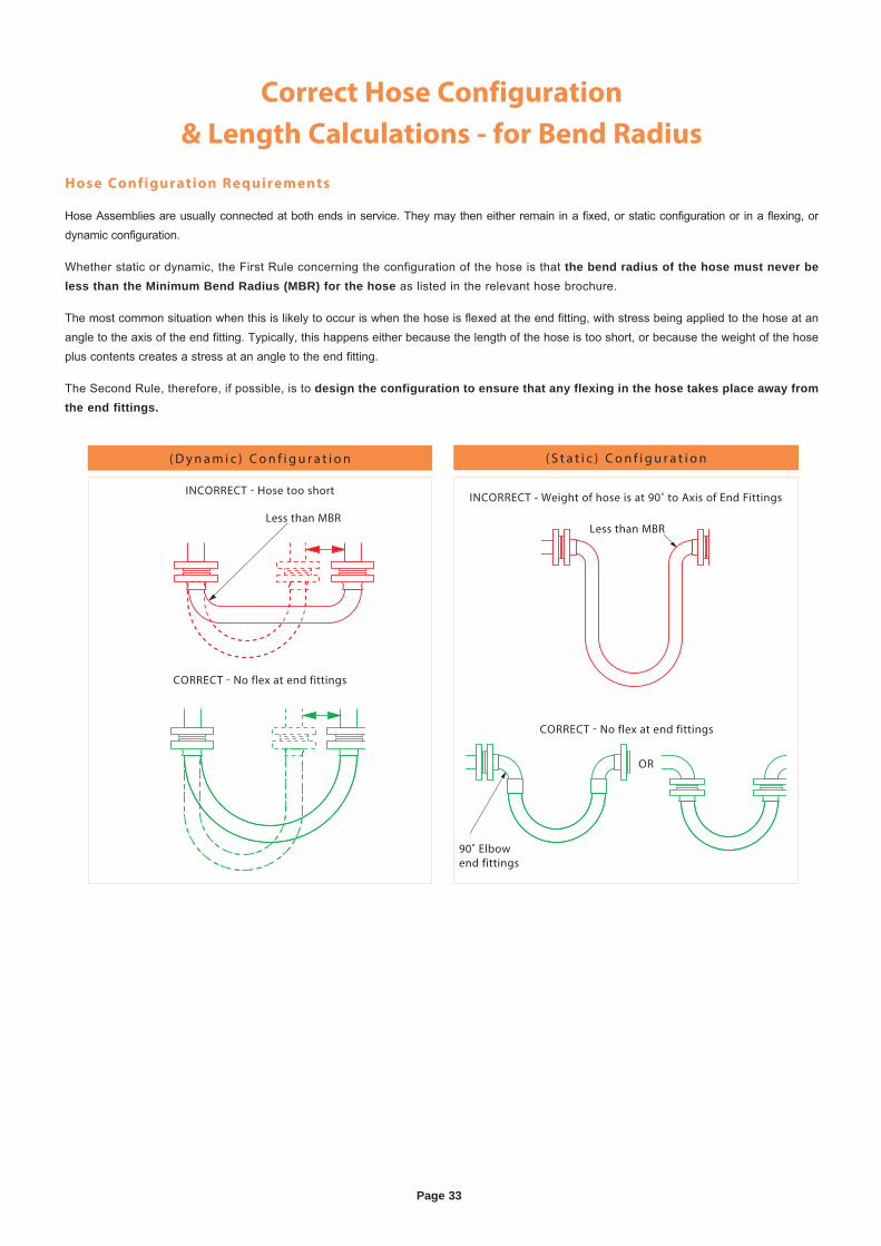
Page 33
Correct Hose Configuration
& Length Calculations - for Bend Radius
Hose Configuration Requirements
Hose Assemblies are usually connected at both ends in service. They may then either remain in a fixed, or static configuration or in a flexing, or dynamic configuration.
Whether static or dynamic, the First Rule concerning the configuration of the hose is that the bend radius of the hose must never be less than the Minimum Bend Radius (MBR) for the hose as listed in the relevant hose brochure.
The most common situation when this is likely to occur is when the hose is flexed at the end fitting, with stress being applied to the hose at an angle to the axis of the end fitting. Typically, this happens either because the length of the hose is too short, or because the weight of the hose plus contents creates a stress at an angle to the end fitting.
The Second Rule, therefore, if possible, is to design the configuration to ensure that any flexing in the hose takes place away from the end fittings.
CORRECT - No flex at end fittings
INCORRECT - Hose too short
( D y n a m i c ) C o n f i g u r a t i o n
Less than MBR
( S t a t i c ) C o n f i g u r a t i o n
INCORRECT - Weight of hose is at 90˚ to Axis of End Fittings
OR
CORRECT - No flex at end fittings
Less than MBR
90˚ Elbowend fittings
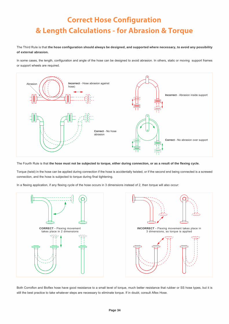
Page 34
Correct Hose Configuration
& Length Calculations - for Abrasion & Torque
The Third Rule is that the hose configuration should always be designed, and supported where necessary, to avoid any possibility of external abrasion.
In some cases, the length, configuration and angle of the hose can be designed to avoid abrasion. In others, static or moving support frames or support wheels are required.
The Fourth Rule is that the hose must not be subjected to torque, either during connection, or as a result of the flexing cycle.
Torque (twist) in the hose can be applied during connection if the hose is accidentally twisted, or if the second end being connected is a screwed connection, and the hose is subjected to torque during final tightening.
In a flexing application, if any flexing cycle of the hose occurs in 3 dimensions instead of 2, then torque will also occur:
Both Corroflon and Bioflex hose have good resistance to a small level of torque, much better resistance that rubber or SS hose types, but it is still the best practice to take whatever steps are necessary to eliminate torque. If in doubt, consult Aflex Hose.
CORRECT - Flexing movementtakes place in 2 dimensions
INCORRECT - Flexing movement takes place in3 dimensions, so torque is applied
Abrasion Incorrect - Hose abrasion against hose)
Incorrect - Abrasion inside support
Correct - No abrasion over support
Correct - No hose abrasion
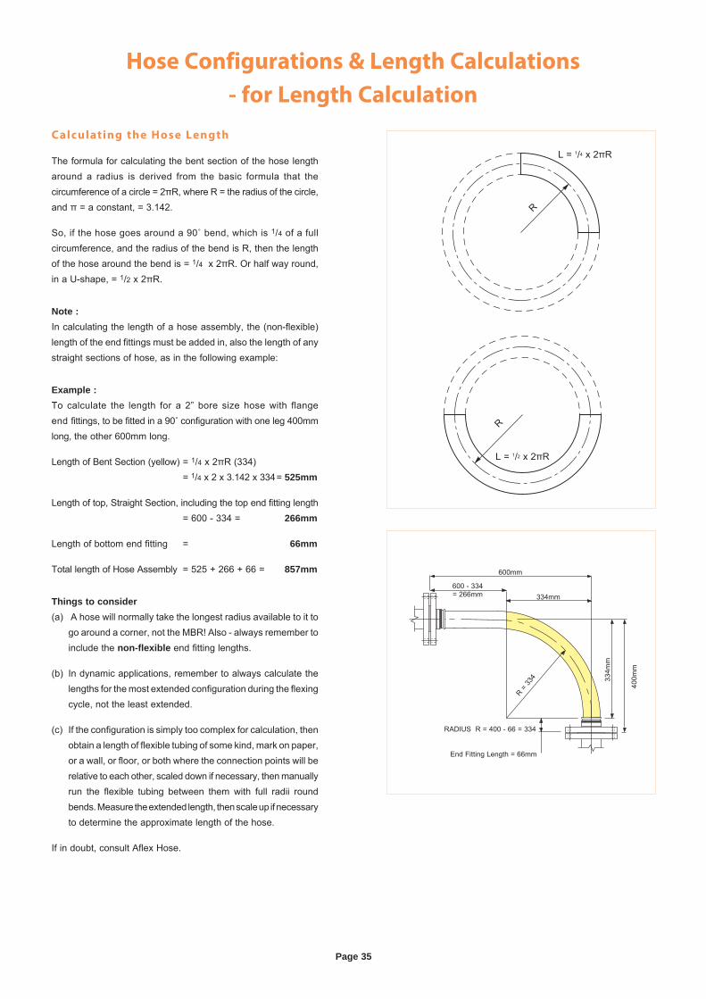
Page 35
Hose Configurations & Length Calculations
- for Length Calculation
Calculating the Hose Length
The formula for calculating the bent section of the hose length around a radius is derived from the basic formula that thecircumference of a circle = 2πR, where R = the radius of the circle, and π = a constant, = 3.142.
So, if the hose goes around a 90˚ bend, which is 1/4 of a full circumference, and the radius of the bend is R, then the length of the hose around the bend is = 1/4 x 2πR. Or half way round, in a U-shape, = 1/2 x 2πR.
Note :In calculating the length of a hose assembly, the (non-flexible) length of the end fittings must be added in, also the length of any straight sections of hose, as in the following example:
Example :To calculate the length for a 2” bore size hose with flange end fittings, to be fitted in a 90˚ configuration with one leg 400mm long, the other 600mm long.
Length of Bent Section (yellow) = 1/4 x 2πR (334) = 1/4 x 2 x 3.142 x 334 = 525mm
Length of top, Straight Section, including the top end fitting length = 600 - 334 = 266mm
Length of bottom end fitting = 66mm
Total length of Hose Assembly = 525 + 266 + 66 = 857mm
Things to consider(a) A hose will normally take the longest radius available to it to go around a corner, not the MBR! Also - always remember to include the non-flexible end fitting lengths.
(b) In dynamic applications, remember to always calculate the lengths for the most extended configuration during the flexing cycle, not the least extended.
(c) If the configuration is simply too complex for calculation, then obtain a length of flexible tubing of some kind, mark on paper, or a wall, or floor, or both where the connection points will be relative to each other, scaled down if necessary, then manually run the flexible tubing between them with full radii round bends. Measure the extended length, then scale up if necessary to determine the approximate length of the hose.
If in doubt, consult Aflex Hose.
L = 1/4 x 2πR
R
R
L = 1/2 x 2πR
400m
m
334m
m334mm
RADIUS R = 400 - 66 = 334
End Fitting Length = 66mm
600mm
600 - 334= 266mm
R = 33
4

Page 36
Conditions of SaleDefinitions
(1) “Aflex Hose” shal l mean Aflex Hose Limited
(2) “Aflex Hose Products” shal l mean those products the Customer is purchasing from Aflex Hose.
(3) “Customer” shal l mean the individual or enti ty that is purchasing Aflex Hose Products hereunder.
(4) “Ful l Product Brochure” shal l mean the brochure for each specif ic product avai lable at http:/ /www.aflex-hose.com/products/.
General
(5) These Condit ions of Sale form the basis of the contract of sale between Aflex Hose and the Customer. In the event of any confl ict between the terms and condit ions set forth in these Condit ions of Sale and any other Customer document, these Condit ions of Sale shal l govern, unless otherwise agreed to in writ ing and authorized and signed for by a Director or General Manager of Aflex Hose.
(6) Unless otherwise agreed to in writ ing, del ivery wil l be at cost from Aflex Hose’s faci l i t ies Brighouse, West Yorkshire, England. Tit le and al l r isks of loss or damage pass to the Customer upon del ivery to the Customer or third party carr ier. Del ivery dates specif ied by Aflex Hose are only Aflex Hose’s best est imates and Aflex Hose’s only responsibi l i ty wi l l be to use reasonable commercial efforts to meet al l specif ied del ivery dates.
Customer Responsibilit ies and Obligations
(7) I t is the Customer’s str ict responsibi l i ty to review al l of the usage condit ions and usage l imitat ions given for the Aflex Hose Products which are intended for use in a part icular appl icat ion, to ensure that the application condit ions are in compliance with those usage l imitat ions. The usage condit ions and l imitat ions are referred to in these Condit ions of Sale, and are further specif ied in the relevant Ful l Product Brochure. The Customer shal l consult the latest, up to date hose product information and Ful l Product Brochure at the t ime of ordering, which are only avai lable and downloadable from the Aflex Hose website at http:/ /www.aflex-hose.com/products/, or on request from Aflex Hose. The Customer here represents and warrants that i t has read and understands the applicable Ful l Product Brochure and the usage condit ions and the usage l imitat ions set forth therein, and has ensured their compliance with the application condit ions.
(8) I f the Customer sel ls or assigns any Aflex Hose Products to any other person or enti ty, the Customer shal l ensure that the f inal end user of the Aflex Hose Products is supplied with these Condit ions to Sale, the applicable Ful l Product Brochures, the Aflex Hose website address, together with noti f icat ion of the requirement to review the usage condit ions and l imitat ions. The Customer shal l include the terms and condit ions set forth herein in i ts Condit ions of Sale to any third party. The Customer hereby agrees and acknowledges that Aflex Hose shal l have no l iabi l i ty whatsoever for claims arising in whole or in part out of the Customer sel l ing or assigning the Aflex Hose Products to a third party that does not use the Aflex Hose Products in accordance with Aflex Hose’s usage requirements and l imi tat ions (“Non-Conforming Use Claims”) . The Customer shal l indemnify and hold harmless Aflex Hose, i ts off icers, directors, employees, aff i l iates and representatives for any and al l claims, damages, penalt ies and losses arising out of or related to Non-Conforming Use Claims.
(9) The Customer agrees and acknowledges that for any intended hose application in which special condit ions apply which are not defined, or not defined suff iciently in the Product Brochure, the Customer shal l wri te to Aflex Hose requesting writ ten advice relat ing to any usage l imitat ions result ing from special condit ions. The Customer shal l ensure the design suitabi l i ty and safety of the Aflex Hose Products in their intended applications, giving part icular consideration to any special condit ion relat ing to, but not restr icted to the chemical and electrostat ic compatibi l i ty of the f luids or gases passing through, the possibi l i ty of dif fusion of f luid or gases through the PTFE hose l ining, the possibi l i ty of external corrosive condit ions, the types and l ikel ihood of excessive mechanical abuse, such as abrasion ( internal or external), crushing, excessive f lexing or vibrat ions, etc. and any excessive temperature and/or pressure “pulsing” condit ions, or any other condit ion which may cause premature hose fai lure. The Customer shal l consider, and take account of the degree of r isk involved in any hose fai lure, including the provision of adequate protection in the event of any r isk to any persons. In appl icat ions where any type of hose
fai lure would lead to f inancial losses i f the hose is not replaced immediately, the Customer agrees and acknowledges that i t shal l be the Customer’s responsibi l i ty to order and hold in stock spare hose(s) accordingly. The Customer shal l advise Aflex Hose in writ ing at the t ime of placing the enquiry and on any purchase order i f there are any special requirements for the hose, including special cleaning, or drying, or extra test ing requirements which are in addit ion to normal industr ial standards. The Customer agrees and acknowledges that Aflex Hose, i ts off icers, directors, employees, aff i l iates and representatives shal l not be held l iable for any claims or obl igations arising out of the Customer’s fai lure to fulf i l l any or al l of i ts responsibi l i t ies set forth in this Section 9.
(10) I f the Customer has any doubts concerning these or any other usage condit ions and l imitat ion or safety parameters, the Customer shal l consult Aflex Hose at the number and address in the Notice Provisions below and request a writ ten response to any queries.
Hose Service Life; 24 Month Warranty
(11) I t is not possible to guarantee a minimum service l i fe for any of the Aflex Hose Products which can be applicable for every type of appl icat ion. As such, Customer acknowledges that, except as provided below in Sections 12, 13 and 14 Aflex Hose is not guaranteeing a minimum service l i fe of any of the Aflex Hose Products.
(12) Service l i fe predict ions or guarantees can only be given in cases where al l the relevant information concerning the application is given in writ ing to Aflex Hose, and Aflex Hose subsequently repl ies in writ ing with the service l i fe predict ion prior to the order being placed.
(13) I f such a writ ten undertaking is not sought and given, Aflex Hose shal l not be held l iable for any Aflex Hose Product fai lure which the Customer considers to be premature, excepting fai lures which are due to faulty materials or manufacturing defects which occur within 24 months or 12 months, as appl icable, of supply as provided in Section 14 below.
(14) Af lex Hose warrants i ts Aflex Hose Products to be free from faulty materials or manufacturing defects from the date of the del ivery, for 24 months; provided, however, that al l Hose Assemblies which are “ETH” (Electr ical Trace Heated) Grade are only warranted for 12 months.
(15) AFLEX HOSE MAKES NO WARRANTY OF ANY KIND WHATSOEVER, EXPRESS OR IMPLIED OTHER THAN AS SPECIFICALLY STATED HEREIN, AND THERE ARE NO WARRANTIES OF MERCHANTABILITY AND/OR FITNESS FOR A PARTICULAR PURPOSE WHICH EXCEED THE OBLIGATIONS AND WARRANTIES SPECIFICALLY STATED HEREIN.
Product Failure
(16) In the event of a product fai lure during the applicable warranty period set forth in Section 14, the Customer shal l provide Aflex Hose with writ ten noti f icat ion within forty-eight (48) hours of discovering the fault . Af lex Hose requires that the Aflex Hose Products not be cut up or tampered with, but should be decontaminated and returned to Aflex Hose, plus a decontamination cert i f icate, for examination and analysis of the fault . The Customer should also provide ful l detai ls in writ ing of the application condit ions under which the hose fai led, including Pressure, Vacuum, Temperature, Flexing and any cycl ing of any of these, also the f luids, gases and any cleaning products passed through the hose, and the total t ime that the hose has been in service also the original order number and the Serial Number for the hose. The Customer may send i ts own witness to the examination i f required. Aflex Hose wil l provide a Non-Conformance Report to the Customer. The Customer shal l bear the cost of returning the Aflex Hose Products that have fai led; provided, however, as set forth in Section 17 below, Aflex Hose shal l reimburse the Customer for any shipping costs i f i t is determined that the fai lure is covered by the warranty set forth in Section 14.
Page 37
Conditions of Sale Continued(17) I f Af lex Hose determines that the faulty materials or a manufacturing defect in the hose is responsible for the hose fai lure, Aflex Hose’s maximum l iabi l i ty shal l be the invoice value of the fai led hose i tself , or the invoice value of the whole customer order as determined by Aflex Hose in i ts sole discret ion, along with any reasonable costs for removal and replacement of the hose, and costs for packing and despatching the fai led hose back to Aflex Hose.
Untested Hose for Self Assembly by Customers
(18) Af lex Hose sometimes supplies “ loose” hose, without end f i t t ings attached to a Self Assembly Customer, who wil l then cut the hose to length and attach end f i t t ings to make up Hose Assemblies for their own use, or for sale to their own customers.
(19) Unless the Customer requests, and Aflex Hose confirms that the ‘ loose’ hose is pressure tested before supply, such test ing is not normally appl ied by Aflex Hose, because this test ing requirement is otherwise satisf ied by the Self Assembly Customer during his own test ing of the f inished Hose Assemblies made up using the “ loose” hose. Self Assembly Customers agree and acknowledge that they are solely responsible for carrying out hydrostat ic pressure test ing of 100% of such assemblies to 11/2 t imes the Maximum Working Pressure (MWP) of the hose assembly as specif ied in the relevant Ful l Product Brochure before supply for end use, to val idate both the hose and the end f i t t ing attachment.
(20) When pressure test ing braided hoses with a plast ic or rubber outer cover, the cover wil l mask any signs of leakage for a t ime. The Customer agrees and acknowledges that after the hydrostat ic pressure test, i t is required to test each covered hose assembly with an internal hel ium gas pressure of 30 Bar (450 psi) for hose sizes up to 1” and 15 Bar (225 psi) for hose sizes above 1”, with the hose assembly immersed in water to enable leak detection by gas bubbles, for a minimum test period of 5 minutes.
(21) The “Self Assembly” Customer agrees and acknowledges that i t shal l determine and approve the Design Suitabi l i ty of the hose assemblies for their intended use before supply and that, except as set forth in Section 22, i t shal l indemnify and hold Aflex Hose harmless from any Claims and Losses arising from Design Suitabi l i ty for a Self Assembly Customer. This includes proceeding in accordance with Section (7) and Section (8) above.
(22) Aflex Hose’s l iabi l i ty is l imited to Aflex Hose Products which are assembled by approved Self Assembly Customers i f al l the hose and f i t t ing components were supplied by Aflex Hose or approved for use by Aflex Hose in writ ing, and they were assembled and tested in accordance with Aflex Hose’s current Manufacturing and Testing Instruct ions, avai lable to approved Self Assemblers in an I-Bay on the Aflex Hose website.
Untested Hose Assemblies
(23) Aflex Hose is sometimes requested by Customers to attach non-standard end f i t t ings to hose assemblies which they, supply, and in some cases i t is not possible to connect these f i t t ings to the Aflex Hose pressure test system. In such cases a “concession not to test” is obtained from the Customer, and a label is attached to the hose assembly, warning that i t requires pressure test ing before use. The Customer agrees and acknowledges that Aflex Hose shal l have no l iabi l i ty whatsoever i f the Customer does not comply with the warning that requires pressure test ing before use.
Force Majeure
(24) Af lex Hose shal l not be l iable for any delay in del ivery, fai lure to del iver or default in performing in accordance with any Customer’s order i f the delay or default is due to: (a) f i res, f loods, str ikes, or other labor disputes, accidents to Aflex Hose’s production faci l i t ies, acts of sabotage, r iots, natural disasters, d i f f icu l t ies procur ing mater ia ls , shortages of raw mater ia ls , interference by civi l or mil i tary authorit ies, whether legal or de facto, governmental restr ic t ions, including but not l imi ted to fai lure to obtain export l icenses, delays in transportat ion or lack of transportat ion faci l i t ies, restr ict ions imposed by federal, state or other governmental legislat ion or, rules or regulat ions thereof, including a force majeure event occurring in respect to one of Aflex Hose’s suppliers; or (b) any other cause beyond Aflex Hose’s control.
Governing Law; Jurisdiction
(25) These Condit ions of Sale and al l r ights, duties and obl igations hereunder, including any and al l other Customer agreements and orders shal l be governed by and subject to English Law.
(26) The Customer acknowledges and agrees that any disputes arising out of or related in any way to this Agreement, including a breach of this Agreement, shal l be brought exclusively in the courts of England, United Kingdom. Furthermore, Customer knowingly, voluntari ly and irrevocably (a) consents to the exclusive jurisdict ion of these courts, (b) waives any immunity or objection, including any objection to personal jur isdict ion or the laying of venue or based on the grounds of forum non conveniens, which i t may have from or to the bringing of the dispute in such jurisdict ion, (c) waives any personal service of any summons, complaint or other process that may be made by any other means permitted by England, United Kingdom, (d) waives any r ight to tr ial by jury, (e) agrees that any such dispute wil l be decided by court tr ial without a jury, (f) understands that i t is giving up valuable legal r ights under this Section 26, including the r ight to tr ial by jury, and that i t voluntari ly and knowingly waives those r ights.
Limitations of Liability
(27) Af lex Hose Products have not been designed or tested for use in aerospace, medical implantat ion or radioactive appl ications, and such use is therefore str ic t ly prohib i ted unless wr i t ten approval from Aflex Hose has been given. Customer agrees and acknowledges that i t is aware of the l imitat ions set forth in this Section 26 and hereby agrees that Aflex Hose shal l not have any l iabi l i ty whatsoever in the event Customer uses Aflex Hose Products for aerospace, medical implantat ion or radioactive appl icat ions. Customer agrees to indemnify Af lex Hose, i ts off icers, directors, employees, aff i l iates and representatives for any and al l Claims and Losses arising out of Customer’s use of the Aflex Hose Products for aerospace, medical implantat ion or radioactive appl icat ions.
(28) Aflex Hose wil l not accept l iabi l i ty for any fai lures of the Aflex Hose Products which are caused by Customers fai l ing to perform their Responsibi l i t ies as specif ied in these Condit ions of Sale.
(29) NOTWITHSTANDING ANYTHING TO THE CONTRARY HEREIN, IN NO EVENT SHALL AFLEX HOSE BE LIABLE FOR ANY SPECIAL, INDIRECT, INCIDENTAL, CONSEQUENTIAL, EXEMPLARY, OR PUNITIVE DAMAGES, LOSS OF PROFITS OR REVENUE, LOSS OF PROCESS PRODUCTS, DAMAGE TO EQUIPMENT, DOWNTIME COSTS, OR LOSS OF USE EVEN IF INFORMED OF THE POSSIBILITY OF SUCH DAMAGES. TO THE EXTENT PERMITTED BY APPLICABLE LAW, THESE EXCLUSIONS AND LIMITATIONS WILL APPLY REGARDLESS OF WHETHER LIABILITY ARISES FROM FAILURE OF THE PRODUCT(S), BREACH OF CONTRACT, FAILURE TO DELIVER ON TIME, WARRANTY, TORT (INCLUDING, BUT NOT LIMITED TO, NEGLIGENCE), BY OPERATION OF LAW, OR OTHERWISE.
Completion of Bulk Hose Orders
(30) Due to the nature of the production of PTFE hose, Aflex Hose reserves the r ight to cal l an order complete in the fol lowing situations. I f a product is a standard Aflex product (as l isted in Aflex product brochures) a f igure of +10% of original order quanti ty can be supplied. I f the product is a non-standard product and outside the Aflex standard product range the f igure of +/- 10% of the original order quanti ty can be supplied. Goods supplied within these parameters would render the order complete.
Notice Provisions
(31) Any writ ten notice required to be provided to Aflex Hose shal l be sent to the fol lowing address: Aflex Hose Limited, Spring Bank Industr ial Estate, Watson Mil l Lane, Sowerby Bridge, Hali fax, West Yorkshire, HX6 3BW.
Exclusion of CISG
(32) The Uni ted Nat ions Convent ion on Contracts for the International Sale of Goods shal l not apply to these Condit ions of Sale and any and al l other Customer documents.

www.aflex-hose.com
UK USASpring Bank Industrial EstateWatson Mill LaneSowerby BridgeHalifaxWest Yorkshire, HX6 3BW
6111 Kellers Church RoadUnit BPipersville,Pa 18947
Tel: +44 (0) 1422 317200
Fax: +44 (0) 1422 836000
Tel: 215 - 766 - 1455
Fax: 215 - 766 - 1688
UK Corrof lon/08.08.14 Rev 36