Embed Size (px)
Citation preview
CORREÇÃO DO FATOR DE POTÊNCIAPOWER FACTOR CORRECTION UNITS
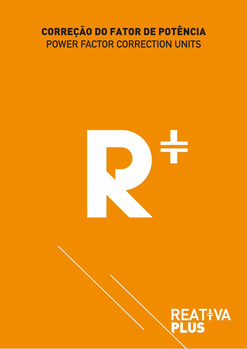
ÍNDICE INDEX
SISTEMAS AUTOMÁTICOS C. F. P. // 1 / 2 / 3
SISTEMAS TIPO 1 // 4
SISTEMAS TIPO 2 // 5
SISTEMAS TIPO 3 // 6
SISTEMAS TIPO 4 // 7
SISTEMAS CFP ESPECIAIS // 8
P. F. C. AUTOMATIC SYSTEMS // 1 / 2 / 3
TYPE 1 UNITS // 4
TYPE 2 UNITS // 5
TYPE 3 UNITS // 6
TYPE 4 UNITS // 7
SPECIAL PFC SYSTEMS // 8
1
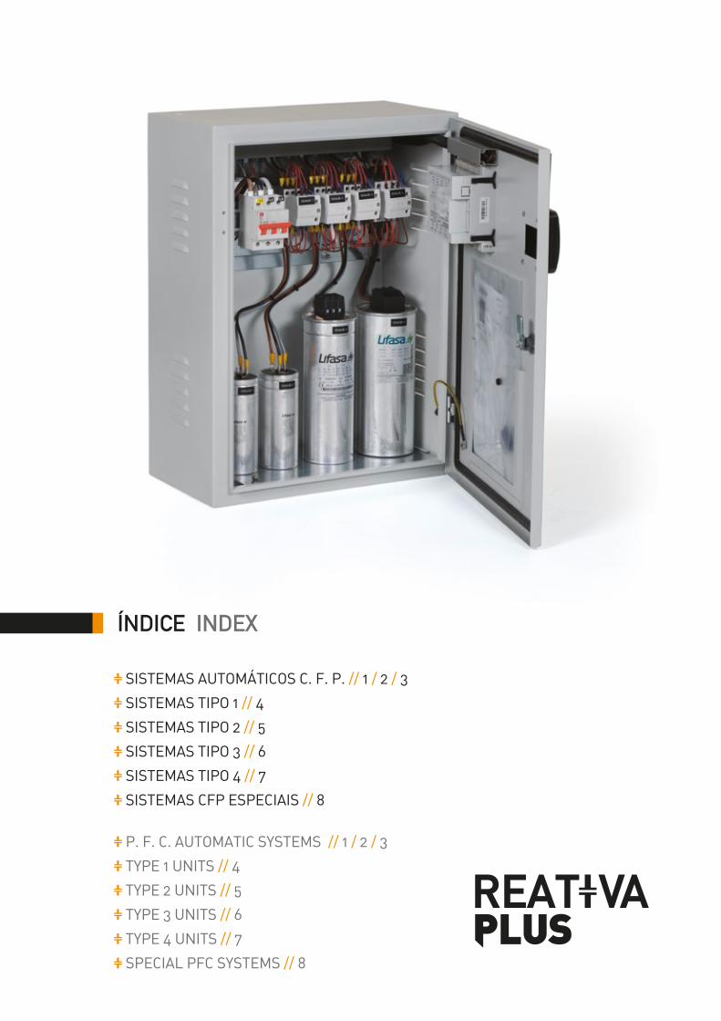
CORREÇÃO DO FATOR DE POTÊNCIAPOWER FACTOR CORRECTION UNITS
MODELO TIPO 1Dimensões (h) 600 x (l) 450 x (p) 250mm
TYPE 1 MODELDimensions (h) 600 x (w) 450 x (d) 250mm
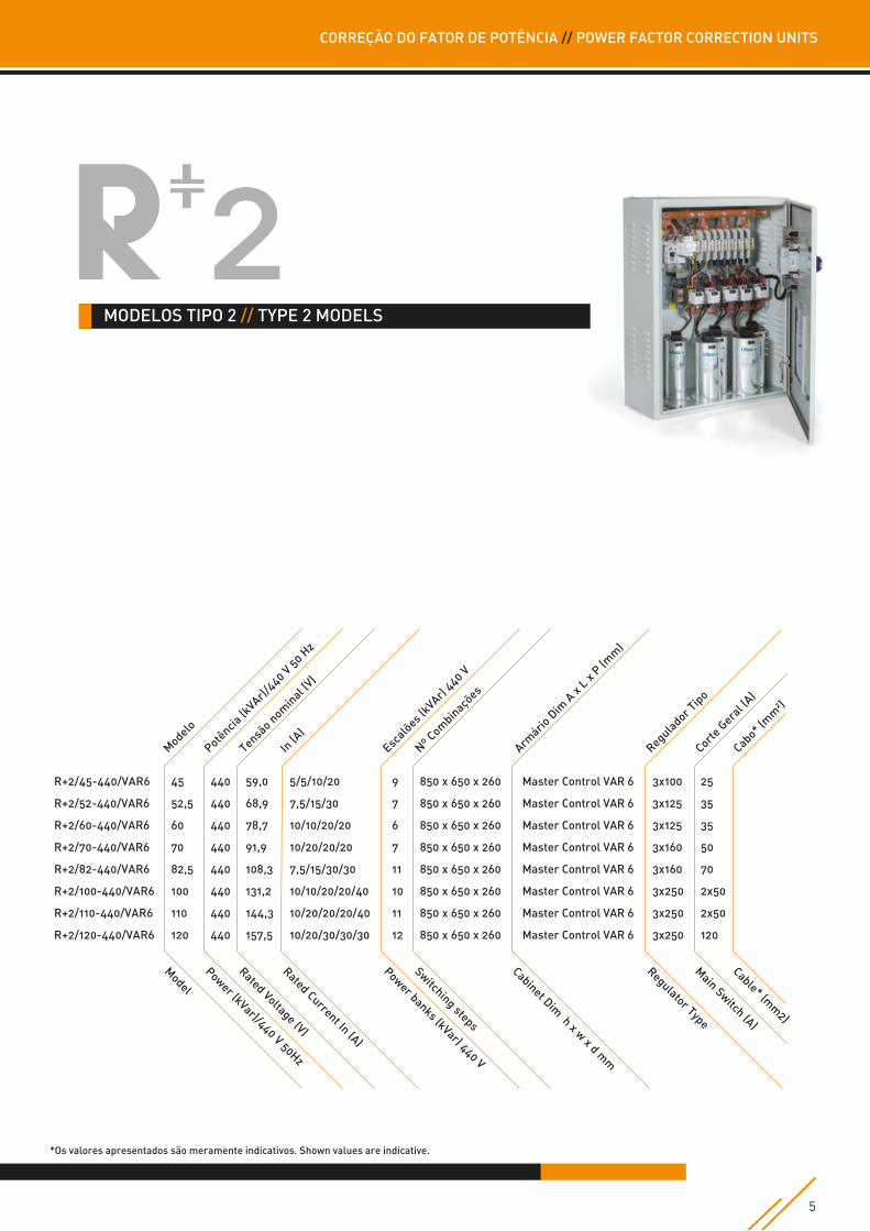
MODELO TIPO 2Dimensões (h) 850 x (l) 650 x (p) 260mm
TYPE 2 MODELDimensions (h) 850 x (w) 650 x (d) 260mm
MODELO TIPO 3Dimensões (h) 1050x (l) 750 x (p) 360mm
TYPE 3 MODELDimensions (h) 1050 x (w) 750 x (d) 360mm
MODELO TIPO 4Dimensões (h) 1800 x (l) 1000 x (p) 400mm
TYPE 4 MODELDimensions (h) 1800 x (w) 1000 x (d) 400mm
2
Tensão nominal440 Vac // Tensão Máxima 1,1 Un// Corrente Máxima 1,3 In
Potência nominal15...420 kVAr
Frequência nominal50 - 60 Hz
Potência nominalÉ referida em termos da tensão nominal e da frequência.
Tensão Circuitos Auxiliares400 Vac
ControladorOs controladores eletrónicos Master Control VAR, permitem o controlo, com alta sensibilidade e precisão, da potencia reativa de uma dada instalação, em função de um cosφ (fator de potência) estabelecido, e da repartição de potencia (n.º de escalões), da bateria de condensadores que equipam. Para além das funções básicas de controlo e comando, da bateria vs instalação, acrescem ainda as seguintes funcionalidades:
• Acesso, local e remoto, aos parâmetros da instalação/rede onde está inserido, como se de um analisador de rede se tratasse, com acesso às diversas grandezas e múltiplos parâmetros.• Função de “Plug & Play” no arranque e configuração dos parâmetros da instalação de destino.• Função de Autoteste e Teste Manual, para ensaio e teste dos diversos escalões/condensadores constituintes da bateria.• Sistema de otimização (FCP-Fast Computerized Program) do fator de potencia, minimizando o n.º de entradas e retiradas dos escalões de serviço.• Funciona com diversos tipos de ligações (3U.3C; 3U.1C; 2U.1C).• Permite a medição da corrente de fugas, associada a alarme, e realizar a identificação e anulação do condensador com defeito.• Dispõe de múltiplos alarmes, para sinalizar possíveis defeitos quer ao nível da bateria, quer da instalação.
SeccionadorModelos R+1, por disjuntor tripolar // Restantes modelos por interruptor seccionador tripolar, com bloqueio de porta
CablagemOs cabos interiores na eletrificação são do tipo N07VK CEI 20-22 anti chama.
ArmárioMetálico de montagem mural ou pedestal. Modular em chapa metálica de 15mm, tratada contra corrosão por fosfatização e de seguida pintada a epoxy poliéster (RAL 7035).Porta frontal com fecho por fechadura. Outras cores a pedido. Suporte de manual e diagrama, no interior da porta.
Grau de proteçãoIP 22 porta fechada
VentilaçãoNatural (ou forçada a pedido dependendo das condições ambientais)
InstalaçãoInterior
MontagemMural ou pedestal
Gama de temperaturas-20 / + 50 ºC
Entrada de cabosModelos R+1/R+2/R+3 pelo topo do armário quando em montagem mural.Modelos R+2/R+3/R+4 pelo rodapé, quando em monta-gem pedestal.
ComutaçãoPor contactores tripolares específicos, para cargas capacitivas, a cada escalão. Para limitar os picos de corrente na inserção, são utilizadas resistências limitadoras. Contactores com bobines a 400 Vac 50 Hz.
ProteçõesCada escalão de condensadores é protegido por disjun-tor magneto-térmico 3P (modelos R+1), ou por fusíveis tripolares, tipo NH00, com alto poder de corte. Também os circuitos auxiliares são protegidos por fusíveis 10x38.
CondensadoresDa marca Lifasa, tipo POLT e POLB HD, cilíndricos, trifási-cos, com capacidade de sobrecargas de 1,8 x In e 1,1 x Un, autoregenerantes, realizados em filme de polipropileno metalizado, estão de acordo com as normas CEI e homologados, dotados de interruptor a sobrepressão e de resistência de descarga.
Rated Power15 … 420 kVar
Rated Voltage440 Vac // Maximum overvoltage 1,1 Un// Maximum overcurrent 1,3 In
Auxiliary Circuits Voltage400 Vac
Rated PowerReferred to rated voltage and frequency.
Rated Frequency50 – 60 Hz
Isolating main SwitchR+1 models, by three-pole circuit breaker // Othermodels by three-pole isolator switch with doorinterlocking block.
WiringThe internal cables are self-extinguishing N07VKCEI 20-22 type.The auxiliary circuits are identified according tothe electrical drawings.
CabinetMetallic for wall and/or floor installation.Modular in 15mm sheet-metal protected againstcorrosion by phosphating treatment.Epossidic dust painted (RAL 7035 color)Front door with locking system.Other colors by request.User Manual support behind the door.
Protection DegreeIP 22 closed door
VentilationNatural (or forced by request, and depending ofthe environmental conditions).
InstallationIndoor
MontageWall or Floor.
Operating Temperature Range-20 / +50 ºC
Cable entrancesBy the cabinet top when wall mounted in the R+1/ R+2/and R+3 models.By the footer when floor mounted in the R+2/ R+3/ andR+4 models.
ContactorsEach bank of capacitors is controlled by specific three-pole contactors, for capacitive loads. To limit the inrushcurrent peaks, each contactor is equipped with insertionresistors. Rated voltage of the auxiliary circuits 400Vac, 50Hz.
ProtectionsEach bank of capacitors is protected by a 3P magneto-thermal circuit breaker (R+1 models), or by a set of three-pole fuses NH00 type with high breaking capacity. The auxiliary circuits are also protected by10x38 fuses.
CapacitorsCEI EN 60831-1/2; IEC 831-1/2
REFERENCE STANDARDS
LV Directive73/23 EEC (93/68)
EquipmentCEI EN 60439-81; IEC 439-1 // CIS EN 61921-1
Protection degreeFor IP40 to IP54
OTHER OPTIONS (BY REQUEST)
ProtectionsProtection and control instruments against overvoltageand overcurrent due to harmonic distortions.
Note: Other models, different features, level of tension andfrequencies available by request.ReativaPlus reserves the right to modify the above-mentionedfeatures and dimensions without previous notice.
CORREÇÃO DO FATOR DE POTÊNCIA // POWER FACTOR CORRECTION UNITS
3
ControllerThe automatic microprocessor PFC controllers Master Control VAR, allow control the reactive power of one plant, with high sensitivity and accuracy, according to established cosφ goals (PFC-Power Factor Correction), and the banks power (number of steps) of the automatic PFC systems.
In addition to the basic control and operation functions of the controller vs plant, it has the following extra features:
• Local and remote access to the measuring of the various parameters of the electrical power distribution system, where the PFC unit is inserted, as if it was an energy analyser, • "Plug & Play" function at start-up and set-up of each plant parameters.• Self-Test and Manual Test operation for testing each banks/capacitors of the unit.• Power factor optimization system (FCP-Fast Computerized Program), for the uniform use of the batteries banks/capacitors.• Works with various types of connections (3U.3C; 3U.1C; 2U.1C).• Allows measurement of leakage current (with alarm notification) and the identification and isolation of the default bank/capacitor.• Has multiple alarms to trigger and monitor possible defects in the battery and/or in the plant.
TECHNICAL DATA
CapacitorsLIFASA brand, type POLT and POLB HD, cylindrical, three-phase, with overloads capacity of 1.8 x In and 1.1 x Un, self-healing, produced in metallized polypropylene film, are according with the CEI standards, equipped with overpressure and discharge resistance light switch.
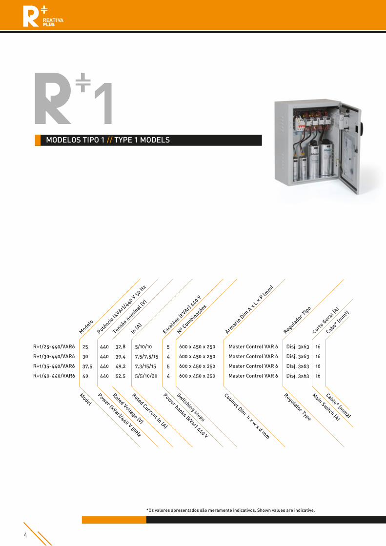
MODELOS TIPO 1 // TYPE 1 MODELS
Power (kVar)/440 V 50Hz
Model
Rated Voltage (V)
Rated Current In (A)
Power banks (kVar) 440 V
Switching steps
Cabinet Dim h x w x d m
m
Regulator Type
Main Switch (A)
Cable* (mm
2)
Modelo
R+1/25-440/VAR6
R+1/30-440/VAR6
R+1/35-440/VAR6
R+1/40-440/VAR6
Potência
(kVAr)/
440 V 50 Hz
Tensão nom
inal (V)
In (A
)Esc
alões (
kVAr) 440 V
Nº Com
binações
Armário
Dim
A x L x P
(mm
)
Regulador T
ipo
Cabo* (m
m²)
Corte G
eral (
A)
25
30
37,5
40
440
440
440
440
32,8
39,4
49,2
52,5
5/10/10
7,5/7,5/15
7,3/15/15
5/5/10/20
5
4
5
4
600 x 450 x 250
600 x 450 x 250
600 x 450 x 250
600 x 450 x 250
Master Control VAR 6
Master Control VAR 6
Master Control VAR 6
Master Control VAR 6
Disj. 3x63
Disj. 3x63
Disj. 3x63
Disj. 3x63
16
16
16
16
4
*Os valores apresentados são meramente indicativos. Shown values are indicative.
CORREÇÃO DO FATOR DE POTÊNCIA // POWER FACTOR CORRECTION UNITS
5
MODELOS TIPO 2 // TYPE 2 MODELS
Power (kVar)/440 V 50Hz
Model
Rated Voltage (V)
Rated Current In (A)
Power banks (kVar) 440 V
Switching steps
Cabinet Dim h x w x d m
m
Regulator Type
Main Switch (A)
Cable* (mm
2)
Modelo
R+2/45-440/VAR6
R+2/52-440/VAR6
R+2/60-440/VAR6
R+2/70-440/VAR6
R+2/82-440/VAR6
R+2/100-440/VAR6
R+2/110-440/VAR6
R+2/120-440/VAR6
Potência
(kVAr)/
440 V 50 Hz
Tensão nom
inal (V)
In (A
)Esc
alões (
kVAr) 440 V
Nº Com
binações
Armário
Dim
A x L x P
(mm
)
Regulador T
ipo
Cabo* (m
m²)
Corte G
eral (
A)
45
52,5
60
70
82,5
100
110
120
440
440
440
440
440
440
440
440
59,0
68,9
78,7
91,9
108,3
131,2
144,3
157,5
5/5/10/20
7,5/15/30
10/10/20/20
10/20/20/20
7,5/15/30/30
10/10/20/20/40
10/20/20/20/40
10/20/30/30/30
9
7
6
7
11
10
11
12
850 x 650 x 260
850 x 650 x 260
850 x 650 x 260
850 x 650 x 260
850 x 650 x 260
850 x 650 x 260
850 x 650 x 260
850 x 650 x 260
Master Control VAR 6
Master Control VAR 6
Master Control VAR 6
Master Control VAR 6
Master Control VAR 6
Master Control VAR 6
Master Control VAR 6
Master Control VAR 6
3x100
3x125
3x125
3x160
3x160
3x250
3x250
3x250
25
35
35
50
70
2x50
2x50
120
*Os valores apresentados são meramente indicativos. Shown values are indicative.
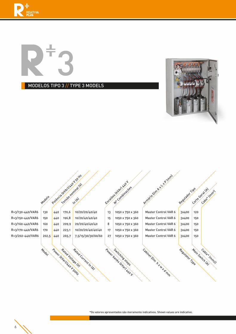
MODELOS TIPO 3 // TYPE 3 MODELS
Power (kVar)/440 V 50Hz
Model
Rated Voltage (V)
Rated Current In (A)
Power banks (kVar) 440 V
Switching steps
Cabinet Dim h x w x d m
m
Regulator Type
Main Switch (A)
Cable* (mm
2)
Modelo
R+3/130-440/VAR6
R+3/150-440/VAR6
R+3/160-440/VAR6
R+3/170-440/VAR6
R+3/202-440/VAR6
Potência
(kVAr)/
440 V 50 Hz
Tensão nom
inal (V)
In (A
)Esc
alões (
kVAr) 440 V
Nº Com
binações
Armário
Dim
A x L x P
(mm
)
Regulador T
ipo
Cabo* (m
m²)
Corte G
eral (
A)
130
150
160
170
202,5
440
440
440
440
440
170,6
196,8
209,9
223,1
265,7
10/20/20/40/40
10/20/40/40/40
20/20/40/40/40
10/20/20/40/40/40
7,5/15/30/30/60/60
13
15
8
17
27
1050 x 750 x 360
1050 x 750 x 360
1050 x 750 x 360
1050 x 750 x 360
1050 x 750 x 360
Master Control VAR 6
Master Control VAR 6
Master Control VAR 6
Master Control VAR 6
Master Control VAR 6
3x400
3x400
3x400
3x400
3x400
120
150
150
150
150
6
*Os valores apresentados são meramente indicativos. Shown values are indicative.
CORREÇÃO DO FATOR DE POTÊNCIA // POWER FACTOR CORRECTION UNITS
7
*Os valores apresentados são meramente indicativos. Shown values are indicative.
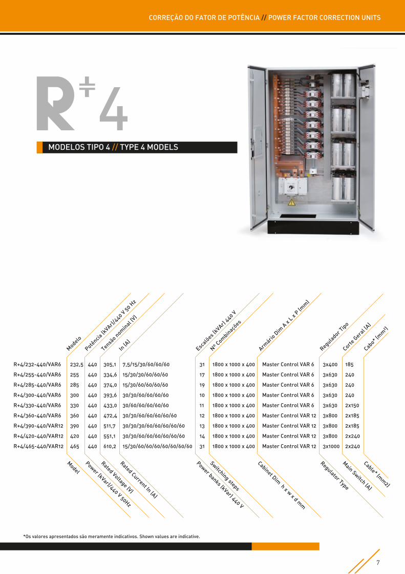
MODELOS TIPO 4 // TYPE 4 MODELS
Power (kVar)/440 V 50Hz
Model
Rated Voltage (V)
Rated Current In (A)
Power banks (kVar) 440 V
Switching steps
Cabinet Dim h x w x d m
m
Regulator Type
Main Switch (A)
Cable* (mm
2)
Modelo
R+4/232-440/VAR6
R+4/255-440/VAR6
R+4/285-440/VAR6
R+4/300-440/VAR6
R+4/330-440/VAR6
R+4/360-440/VAR6
R+4/390-440/VAR12
R+4/420-440/VAR12
R+4/465-440/VAR12
Potência
(kVAr)/
440 V 50 Hz
Tensão nom
inal (V)
In (A
)Esc
alões (
kVAr) 440 V
Nº Com
binações
Armário
Dim
A x L x P
(mm
)
Regulador T
ipo
Cabo* (m
m²)
Corte G
eral (
A)
232,5
255
285
300
330
360
390
420
465
440
440
440
440
440
440
440
440
440
305,1
334,6
374,0
393,6
433,0
472,4
511,7
551,1
610,2
7,5/15/30/60/60/60
15/30/30/60/60/60
15/30/60/60/60/60
30/30/60/60/60/60
30/60/60/60/60/60
30/30/60/60/60/60/60
30/30/30/60/60/60/60/60
30/30/60/60/60/60/60/60
15/30/60/60/60/60/60/60/60
31
17
19
10
11
12
13
14
31
1800 x 1000 x 400
1800 x 1000 x 400
1800 x 1000 x 400
1800 x 1000 x 400
1800 x 1000 x 400
1800 x 1000 x 400
1800 x 1000 x 400
1800 x 1000 x 400
1800 x 1000 x 400
Master Control VAR 6
Master Control VAR 6
Master Control VAR 6
Master Control VAR 6
Master Control VAR 6
Master Control VAR 12
Master Control VAR 12
Master Control VAR 12
Master Control VAR 12
3x400
3x630
3x630
3x630
3x630
3x800
3x800
3x800
3x1000
185
240
240
240
2x150
2x185
2x185
2x240
2x240
8
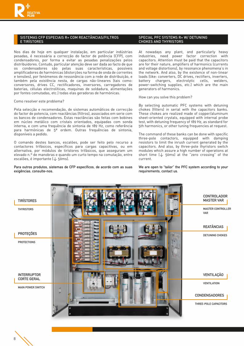
SISTEMAS CFP ESPECIAIS R+ COM REACTÂNCIAS/FILTROS E TIRÍSTORES
Nos dias de hoje em qualquer instalação, em particular indústrias pesadas, é necessária a correcção do factor de potência (CFP), com condensadores, por forma a evitar as pesadas penalizações pelos distribuidores. Contudo, particular atenção deve ser dada ao facto de que os condensadores são pelas suas características, possíveis amplificadores de harmónicas (distorções na forma de onda de correntes e tensões), por fenómenos de ressonância com a rede de distribuição, e também pela existência nesta, de cargas não-lineares (tais como: conversores, drives CC, rectificadores, inversores, carregadores de baterias, células electrolíticas, maquinas de soldadura, alimentações por fontes comutadas, etc.) todas elas geradoras de harmónicas.
Como resolver este problema?
Pela selecção e recomendação, de sistemas automáticos de correcção do factor de potencia, com reactâncias (filtros), associados em serie com os bancos de condensadores. Estas reactâncias são feitas com bobines em núcleo metálico com cristais orientados, equipadas com sonda interna, e com uma frequência de sintonia de 189 Hz, como referência para harmónicas de 5ª ordem. Outras frequências de sintonia, disponíveis a pedido.
O comando destes bancos, escalões, pode ser feito pelo recurso a contactores trifásicos, específicos para cargas capacitivas, ou em alternativa, por módulos de tirístores trifásicos, que asseguram um elevado n.º de manobras e quando um curto tempo na comutação, entre escalões, é importante (< 50ms).
Para outros produtos, sistemas de CFP específicos, de acordo com as suas exigências, consulte-nos.
SPECIAL PFC SYSTEMS R+ W/ DETUNING CHOKES AND THYRISTORS
At nowadays any plant, and particularly heavy industries, need power factor correction with capacitors. Attention must be paid that the capacitors are for their nature, amplifiers of harmonics (currents and voltage distortions), by resonance phenomena’s in the network. And also, by the existence of non-linear loads (like: converters, DC drives, rectifiers, inverters, battery chargers, electrolytic cells, welders, power-switching supplies, etc.) which are the main generators of harmonics.
How can you solve this problem?
By selecting automatic PFC systems with detuning chokes (filters) in serial with the capacitors banks. These chokes are realized made of copper/aluminum sheet-oriented crystals, equipped with internal probe test, with detuning frequency of 189 Hz, as standard for 5th harmonics, or other tuning frequencies at request.
The command of these banks can be done with specific three-pole contactors, equipped with damping resistors to limit the inrush current generated by the capacitors. And also, by three-pole thyristors switch modules which assure a high number of operations at short time (< 50ms) at the “zero crossing” of the current.
We are open to “tailor” the PFC system according to your requirements, contact us.
CONTROLADORMASTER VAR
MASTER CONTROLLERVAR
VENTILAÇÃO
VENTILATION
REATÂNCIAS
DETUNING CHOKES
CONDENSADORES
THREE-POLE CAPACITORS
PROTEÇÕES
PROTECTIONS
TIRÍSTORES
THYRISTORS
INTERRUPTORCORTE GERAL
MAIN POWER SWITCH
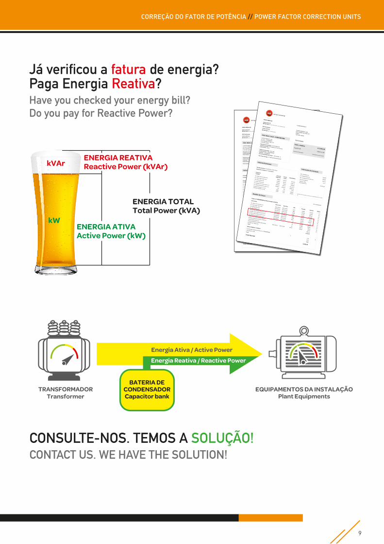
TRANSFORMADORTransformer
Energia Ativa / Active Power
EQUIPAMENTOS DA INSTALAÇÃOPlant Equipments
Energia Reativa / Reactive Power
BATERIA DECONDENSADORCapacitor bank
ENERGIA ATIVAActive Power (kW)
ENERGIA TOTALTotal Power (kVA)
kVArENERGIA REATIVAReactive Power (kVAr)
Já verificou a fatura de energia?Paga Energia Reativa?Have you checked your energy bill?Do you pay for Reactive Power?
9
CORREÇÃO DO FATOR DE POTÊNCIA // POWER FACTOR CORRECTION UNITS
CONSULTE-NOS. TEMOS A SOLUÇÃO!CONTACT US. WE HAVE THE SOLUTION!

CTR
P18
.0
DISTRIBUIDOR // DISTRIBUTOR