Embed Size (px)
Citation preview

1
Corporate AntennaSolutions380-512MHz746-870MHz

2
About RFI
RFI is a global technology solutions company, specialising in wireless coverage. RFI has one of the largest, most innovative and experienced wireless solutions teams with dedicated engineers, product managers, deployment engineers, logistics, distribution and R&D staff.
Our network of international sales offices means that all customers get the attention and advice they require, providing local support on a global scale. This includes our 16,000 ft² American office and distribution center with local product stock and engineering services for the Americas region.
RFI develops, manufactures and distributes world-class, high performance, wireless products including; antenna systems, rebroadcast & monitoring equipment, power systems and cabling and connectors. RFI is recognised as a market leader in wireless products and offers the best products backed with outstanding technical support.
RFI is continually strengthening its technology solutions portfolio, including the recent acquisition of Maxon Australia, allowing us to offer industry leading M2M solutions.
Award Winning Manufacturing
RFI is proud to be an award winning manufacturer with wireless coverage products that perform on a global stage. RFI Technology solutions are manufactured in Australia and exported to 80 + countries. RFI operates manufacturing sites in Victoria and South Australia, both with a proud history in quality, safety and environmental performance. Our two sites include Australia’s largest antenna manufacturing facility, producing world class Antenna and Multicoupling Systems for both Domestic and International Markets and the only Australian manufacturing site producing frequency translating repeater systems.
Leading-Edge Technology
RFI utilises leading RF design and drafting modelling packages. Our world-class testing environment has an extensive suite of test equipment and custom automated testing.
3
Corporate Antenna Family
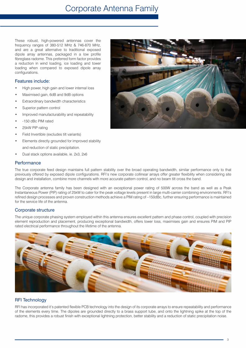
These robust, high-powered antennas cover the frequency ranges of 380-512 MHz & 746-870 MHz, and are a great alternative to traditional exposed dipole array antennas, packaged in a low profile fibreglass radome. This preferred form factor provides a reduction in wind loading, ice loading and tower loading when compared to exposed dipole array configurations.
Features include:• High power, high gain and lower internal loss
• Maximised gain, 6dB and 9dB options
• Extraordinary bandwidth characteristics
• Superior pattern control
• Improved manufacturability and repeatability
• -150 dBc PIM rated
• 25kW PIP rating
• Field Invertible (excludes tilt variants)
• Elements directly grounded for improved stability
and reduction of static precipitation.
• Dual stack options available, ie. 2x3, 2x6
PerformanceThe true corporate feed design maintains full pattern stability over the broad operating bandwidth, similar performance only to that previously offered by exposed dipole configurations. RFI’s new corporate collinear arrays offer greater flexibility when considering site design and installation, combine more channels with more accurate pattern control, and no beam tilt cross the band.
The Corporate antenna family has been designed with an exceptional power rating of 500W across the band as well as a Peak Instantaneous Power (PIP) rating of 25kW to cater for the peak voltage levels present in large multi-carrier combining environments. RFI’s refined design processes and proven construction methods achieve a PIM rating of –150dBc, further ensuring performance is maintained for the service life of the antenna.
Corporate structureThe unique corporate phasing system employed within this antenna ensures excellent pattern and phase control, coupled with precision element reproduction and placement, producing exceptional bandwidth, offers lower loss, maximises gain and ensures PIM and PIP rated electrical performance throughout the lifetime of the antenna.
RFI TechnologyRFI has incorporated it’s patented flexible PCB technology into the design of its corporate arrays to ensure repeatability and performance of the elements every time. The dipoles are grounded directly to a brass support tube, and onto the lightning spike at the top of the radome, this provides a robust finish with exceptional lightning protection, better stability and a reduction of static precipitation noise.

4
Corporate Collinear Antennas
CC380 Series 380-420 MHz
These industry leading PIM rated collinear arrays allow site operators to combine, with complete integrity, a large number of communications services into a single, low profile collinear antenna array. The true corporate feed of these arrays maintains total pattern integrity over a very broad operating bandwidth, similar to that previously available only in exposed dipole configurations. This is now achieved in the preferred from factor of a fully enclosed fiberglass radome.
The corporate collinears employ a unique corporate phasing system enabling precision control of the element placements ensuring phase purity resulting in exceptional bandwidth and electrical performance. Gain is maximized and side lobes reduced dramatically.
The dipole elements are soldered to a brass support tube which is directly connected to the mounting tube and the lightning spike at the top of the antenna.
Features:• Extraordinary bandwidth characteristics with superior pattern control
over an extended band coverage
• Light weight dipole construction with low center of gravity reducing tip deflection and sway
• Sealed PTFE insulated cables in harnessing ensure high power capability
• CC380-33 operates as 2 individual antennas in the one radome
• -150dBc Passive Intermodulation (PIM) rating
Typical VSWR Response (CC380-06)
VSW
R
Frequency (MHz)
Model Number CC380-06 CC380-33
Nominal Gain dBd (dBi) 5 (7.1) 2 x 3 (5.1)
Frequency MHz 380 - 420
Tuned Bandwidth Full Band
VSWR (Return Loss) <1.5:1 (14dB)
Nominal Impedance Ω 50
Vertical Beamwidtho 15 40
Horizontal Beamwidtho Omni +/- 0.5dB
Input Power W 250
Passive IM 3rd order (2x20W) dBc -150
Electrical
Model Number CC380-06 CC380-33
Construction & Configuration Composite fiberglass sky blue radome, aluminum mounting tube
Length m (ft) 3.1 (10) 3.8 (12.5)
Radome Diameter mm (inches) 76 (3)
Weight kg (lbs) 11 (24) 15 (33)
Shipping Weight kg (lbs) 24 (53) 35 (77)
Shipping Dimensions mm(inches)
H 139 (6)
W 139 (6)
L 3510 (138) 4400 (173)
Termination 7/16” DIN fixed female 2 x 7/16” DIN fixed female
Mounting Area mm (inches) 500mm x 90mm diam. (20 X 3.5) diam. Aluminum
Suggested Clamps (not included) 2 x UC-114
Projected area cm² (ft²)
no ice 2600 (2.8) 3340 (3.6)
with ice 3060 (3.3) 4000 (4.3)
Lateral Thrust @ 160km/h N (100mph lbs)
301 (68) 401 (90)
Wind Gust No ice >240 (>150)
Torque @160km/h Nm (100mph ft-lbs)
335 (247) 580 (428)
Mechanical
USA Patent: 7,365,698, and Australian Patent: 2005904524
350 360 370 380 390 400 410 420 430 440 450
2.0
1.9
1.8
1.7
1.6
1.5
1.4
1.3
1.2
1.1

5
Corporate Collinear Antennas
CC450 Series 450-512 MHz
These industry leading, full featured corporate collinear arrays allow site operators to combine, with complete integrity, a large number of communications services into a single, low profile antenna solution. The corporate feed design employed by RFI maintains superior pattern control, allowing gain to be maximised with zero tilt variation over a very broad bandwidth, comparable to that only previously available in exposed dipole array configurations. This is achieved in the preferred form factor of a fully enclosed fibreglass radome, providing a reduction in wind loading, ice loading and tower loading by comparison.
The CC450 series have been designed with an exceptional power rating of 500W across the band as well as a Peak Instantaneous Power (PIP) rating of 25kW to cater for the peak voltage levels present in large multi-carrier combining environments. RFI’s refined design processes and proven construction methods achieve a PIM rating of –150dBc, further ensuring performance is maintained for the service life of the antenna.
Features:• 500W continuous power rating
• -150dBc passive intermodulation (PIM) rating
• Preset downtilt variations of 3 and 6 degrees available in the CC450-09 & CC450-06 models - see notes (1)
• 25 kW peak instantaneous Power (PIP) rating
• DC grounding on all elements for the ultimate in lightning protection and dissipation of static noise
• CC450-06 and CC450-09 are field invertible (excluding tilt variations and -66 model)
Model Number CC450-66 CC450-06 CC450-09
Nominal Gain dBi (dBd) 2 x 6.0 (8.1) 6.0 (8.1) 8.5 (10.5)
Frequency MHz 450 - 512
Tuned Bandwidth Full Band
VSWR (Return Loss) <1.5:1 (14dB)
Nominal Impedance Ω 50°
Vertical Beamwidth° 15 8
Horizontal Beamwidth° Omni +/- 0.5dB
Power W 500
Passive IM 3rd order (dBc) -150
Peak Instantaneous Power (kW) 25
Model Number CC450-66 CC450-06 CC450-09
Construction & Configuration Sky blue fiberglass radome
Length mm (inches) 5406 (213) 2876 (113) 5206 (205)
Radome Diameter mm (inches) 77 (3)
Weight kg (lbs) 25.5 (119) 10.0 (22) 24.5 (54)
Termination 7/16” DIN fixed female + DIN cable tail 7/16” DIN fixed female
Shipping Dimensions mm (inches)
H 115 (4.5)
W 115 (4.5)
L 5606 (221) 3076 (122) 5406 (215)
Mounting Area mm (inches)750mm x 89.0mm diameter
(20” x 3.5”)Eco-filmTM plated aluminium
500mm x 89.0mm diameter (20” x 3.5”)
Eco-filmTM plated aluminium
750mm x 89.0mm diameter (30” x 3.5”)
Eco-filmTM plated aluminium
Suggested Clamps 2 x UC-114
Projected area cm2
(ft2)
No ice 4799 (5.2) 2378 (2.6) 4615 (5)
With ice 6076 (6.5) 2903 (3.1) 5843 (6.3)
Lateral Thrust @ 160km/h N (100mph lbs)
569 (128) 282 (63) 547 (123)
Wind Gust Rating km/h (mph) >240 (>150)
Torque @160km/h Nm (100mph ft-lbs)
1338 (987) 342 (252) 1232 (987)
Typical VSWR Response (CC450-06)
VSW
R
Electrical
Mechanical
2.00
1.90
1.80
1.70
1.60
1.50
1.40
1.30
1.20
1.10
Frequency (MHz)733 748 763 778 793 808 823 838 853 868 883
(1) Downtilt versions and dual -66 version cannot be field inverted
Note: Preset downtilt variations of -3 and -6 degrees are available in both the CC450-06 and CC450-09 models. Simply add -T3 or -T6 at the end of the model being ordered Eg. CC450-09-T3

6
Corporate Collinear Antennas
CC807 Series 746-870 MHz
These industry leading PIM and PIP rated collinear arrays allow site operators to combine, with complete integrity, a large number of communications services into a single, low profile collinear antenna array.
The true corporate feed of these arrays maintains total pattern integrity over a very broad operating bandwidth, similar to that previously available only in exposed dipole configurations. This is now achieved in the preferred from factor of a fully enclosed fiberglass radome. The corporate collinears employ a unique corporate phasing system enabling precision control of the element placements ensuring phase purity resulting in exceptional bandwidth and electrical performance.
Gain is maximized and side lobes reduced dramatically. In a patented design approach the individual dipole elements including matching network are fabricated entirely of a flexible circuit board. The dipole elements are soldered to a brass support tube which is directly connected to the mounting tube and the lightning spike at the top of the antenna.
Features:• 500W continuous power rating for CC807-11, CC807-08, CC807-06
• -150dBc passive intermodulation (PIM) rating
• 25 kW peak instantaneous Power (PIP) rating
• Extraordinary bandwidth characteristics with superious pattern control
• DC grounding on all elements for the ultimate in lightning protection and dissipation of static noise
• Pre-set downtilit variations of 1, 3 and 5 degrees are available on CC807-08 & CC807-11 Models (see notes)
Model Number CC807-03 CC807-06 CC807-08 CC807-11
Nominal Gain dBi (dBd) 3 (5.1) 6 (8.1) 8 (10.1) 10.5 (12.6)
Frequency MHz 746 - 870
Tuned Bandwidth Full Band
VSWR (Return Loss) <1.5:1
Nominal Impedance Ω 50
Vertical Beamwidth° 28 17 9 4.5
Horizontal Beamwidth° Omni +/- 0.5dB
Power W 250 500
Passive IM 3rd order (dBc) -150
Peak Instantaneous Power (kW) 25
Model Number CC807-03 CC807-06 CC807-08 CC807-11
Construction & Configuration Composite fiberglass sky, blue radome, aluminum mounting tube
Length m (ft) 1.3 (4.3) 1.8 (6) 2.9 (9.5) 5.3 (17.4)
Radome Diameter mm (inches) 76 (3)
Weight kg (lbs) 4 (9) 7 (16) 12 (27) 22 (49)
Shipping Weight kg (lbs) 8 (18) 11 (25) 18 (40) 30 (66)
Shipping Dimensions mm (inches)
H 139 (6)
W 139 (6)
L 1400 (55) 1900 (75) 3000 (118) 5600 (220)
Termination 7/16” DIN fixed female
Suggested Clamps (not included) 2 x UC-114
Invertible Mounting Yes (1)
Projected area cm2 (ft2)No ice 806 (0.9) 1268 (1.4) 2320 (2.5) 4560 (4.9)
With ice 1048 (1.2) 1571 (1.7) 2880 (3.1) 5760 (6.2)
Lateral Thrust @ 160km/h N (100mph lbs) 96 (22) 150 (34) 276 (62) 540 (121)
Wind Gust Rating km/h (mph) >240 (>150)
Torque @160km/h Nm (100mph ft-lbs) 20 (15) 73 (54) 278 (205) 1032 (761)
(1) Downtilt versions can not be field inverted.
Note: Pre-set downtilt variations of 1, 3 and 5 degrees are available in the following models CC807-08, CC807-11. Simply add -T1, -T3 or -T5 at the end of the model being ordered. E.g. CC807-08-T3,
CC807-11-T3.
USA Patent: 7,365,698, and Australian Patent: 2005904524
Typical VSWR Response (CC807-06)
VSW
R
Frequency (MHz)
Electrical
Mechanical
733 748 763 778 793 808 823 838 853 868 883
2.00
1.90
1.80
1.70
1.60
1.50
1.40
1.30
1.20
1.10

7
Corporate Collinear Antennas
Corporate Antenna Range
With such wide bandwidth performance and exceptional PIM (-150dBc) and PIP (25kW) ratings, this range offers up a great compliment to our multicoupling systems, combining more channels with complete integrity and pattern stability. A great alternative to dipole arrays; saving on space as well as tower loading, with a reduction in both ice and wind loading as well.
Model Bandwidth MHz Power W Length m Gain dBd Tilt* PIM dBc
CC380-06 380-420 250 3.1 5 0° -150
CC380-33 380-420 250 3.8 2 x 3 0° -150
CC380-06 E Plane CC380-33 E Plane
Model Bandwidth (MHz) Power (W) Length (m) Gain (dBd) Tilt* PIM (dBc) PIP (kW)
CC450-06 450 - 512 500 2.9 6 0° -150 25
CC450-06-T3 450 - 512 500 2.9 6 -3° -150 25
CC450-06-T6 450 - 512 500 2.9 6 -6° -150 25
CC450-66 450 - 512 500 5.4 2x6 0° -150 25
CC450-09 450 - 512 500 5.2 8.5 0° -150 25
C450-09-T3 450 - 512 500 5.2 8.5 -3° -150 25
CC450-09-T6 450 - 512 500 5.2 8.5 -6° -150 25
0°180°
-90°
10°
100°
-170°
-80°
20°
110°
-160°
-70°
30°
120°
-150°
-60°
40°
130°
-140°
-50°
50°
140°
-130°
-40°
60°
150°
-120°
-30°
70°
160°
-110°
-20°
80°
170°
-100°
-10°
0 dB
-5 dB
-10 dB
-15 dB
-20 dB
-25 dB
0°180°
-90°
10°
100°
-170°
-80°
20°
110°
-160°
-70°
30°
120°
-150°
-60°
40°
130°
-140°
-50°
50°
140°
-130°
-40°
60°
150°
-120°
-30°
70°
160°
-110°
-20°
80°
170°
-100°
-10°
0 dB
-5 dB
-10 dB
-15 dB
-20 dB
-25 dB
0°180°
-90°
10°
100°
-170°
-80°
20°
110°
-160°
-70°
30°
120°
-150°
-60°
40°
130°
-140°
-50°
50°
140°
-130°
-40°
60°
150°
-120°
-30°
70°
160°
-110°
-20°
80°
170°
-100°
-10°
0 dB
-5 dB
-10 dB
-15 dB
-20 dB
-25 dB
0°180°
-90°
10°
100°
-170°
-80°
20°
110°
-160°
-70°
30°
120°
-150°
-60°
40°
130°
-140°
-50°
50°
140°
-130°
-40°
60°
150°
-120°
-30°
70°
160°
-110°
-20°
80°
170°
-100°
-10°
0 dB
-5 dB
-10 dB
-15 dB
-20 dB
-25 dB
*Downtilt versions cannot be field inverted
0°180°
-90°
10°
100°
-170°
-80°
20°
110°
-160°
-70°
30°
120°
-150°
-60°
40°
130°
-140°
-50°
50°
140°
-130°
-40°
60°
150°
-120°
-30°
70°
160°
-110°
-20°
80°
170°
-100°
-10°
0 dB
-5 dB
-10 dB
-15 dB
-20 dB
-25 dB
CC450-06-T3 E PlaneCC450-06 E Plane
CC450-09 E Plane
0°180°
-90°
10°
100°
-170°
-80°
20°
110°
-160°
-70°
30°
120°
-150°
-60°
40°
130°
-140°
-50°
50°
140°
-130°
-40°
60°
150°
-120°
-30°
70°
160°
-110°
-20°
80°
170°
-100°
-10°
0 dB
-5 dB
-10 dB
-15 dB
-20 dB
-25 dB
CC450-06-T6 E Plane
CC450-09-T3 E Plane CC450-09-T6 E Plane

8
Corporate Collinear Antennas
700/800 MHz Corporate Antenna Range
Model Bandwidth MHz Power W Length m Gain dBd Tilt* PIM dBc PIP kW
CC807-03 746-870 250 1.3 3 0° -150 25
CC806-66 746-870 250 2.7 2 x 5 0° -150 -
CC807-06 746-870 500 1.8 6 0° -150 25
CC807-06-T3 746-870 500 1.8 6 -3° -150 25
CC807-06-T5 746-870 500 1.8 6 -5° -150 25
Model Bandwidth MHz Power W Length m Gain dBd Tilt* PIM dBc PIP kW
CC807-08 746-870 500 2.9 8 0° -150 25
CC807-08-T1 746-870 500 2.9 8 -1° -150 25
CC807-08-T3 746-870 500 2.9 8 -3° -150 25
CC807-08-T5 746-870 500 2.9 8 -5° -150 25
CC807-08-T5-INV 746-870 500 2.9 8 -5° invert mount -150 25
Model Bandwidth MHz Power W Length m Gain dBd Tilt* PIM dBc PIP kW
CC807-11 746-870 500 5.3 10.5 0° -150 25
CC807-11-T1 746-870 500 5.3 10.5 -1° -150 25
CC807-11-T3 746-870 500 5.3 10.5 -3° -150 25
CC807-11-T5 746-870 500 5.3 10.5 -5° -150 25
CC807-08 E Plane CC807-08-T1 E Plane CC807-08-T3 E Plane CC807-08-T5 E Plane
CC807-11 E Plane CC807-11-T1 E Plane CC807-11-T3 E Plane CC807-11-T5 E Plane
CC807-06 E PlaneCC806-66 E Plane CC807-06-T5 E Plane
*Downtilt versions cannot be field inverted
0°180°
-90°
10°
100°
-170°
-80°
20°
110°
-160°
-70°
30°
120°
-150°
-60°
40°
130°
-140°
-50°
50°
140°
-130°
-40°
60°
150°
-120°
-30°
70°
160°
-110°
-20°
80°
170°
-100°
-10°
0 dB
-5 dB
-10 dB
-15 dB
-20 dB
-25 dB
0°180°
-90°
10°
100°
-170°
-80°
20°
110°
-160°
-70°
30°
120°
-150°
-60°
40°
130°
-140°
-50°
50°
140°
-130°
-40°
60°
150°
-120°
-30°
70°
160°
-110°
-20°
80°
170°
-100°
-10°
0 dB
-5 dB
-10 dB
-15 dB
-20 dB
-25 dB
0°180°
-90°
10°
100°
-170°
-80°
20°
110°
-160°
-70°
30°
120°
-150°
-60°
40°
130°
-140°
-50°
50°
140°
-130°
-40°
60°
150°
-120°
-30°
70°
160°
-110°
-20°
80°
170°
-100°
-10°
0 dB
-5 dB
-10 dB
-15 dB
-20 dB
-25 dB
0°180°
-90°
10°
100°
-170°
-80°
20°
110°
-160°
-70°
30°
120°
-150°
-60°
40°
130°
-140°
-50°
50°
140°
-130°
-40°
60°
150°
-120°
-30°
70°
160°
-110°
-20°
80°
170°
-100°
-10°
0 dB
-5 dB
-10 dB
-15 dB
-20 dB
-25 dB
0°180°
-90°
10°
100°
-170°
-80°
20°
110°
-160°
-70°
30°
120°
-150°
-60°
40°
130°
-140°
-50°
50°
140°
-130°
-40°
60°
150°
-120°
-30°
70°
160°
-110°
-20°
80°
170°
-100°
-10°
0 dB
-5 dB
-10 dB
-15 dB
-20 dB
-25 dB
0°180°
-90°
10°
100°
-170°
-80°
20°
110°
-160°
-70°
30°
120°
-150°
-60°
40°
130°
-140°
-50°
50°
140°
-130°
-40°
60°
150°
-120°
-30°
70°
160°
-110°
-20°
80°
170°
-100°
-10°
0 dB
-5 dB
-10 dB
-15 dB
-20 dB
-25 dB
0°180°
-90°
10°
100°
-170°
-80°
20°
110°
-160°
-70°
30°
120°
-150°
-60°
40°
130°
-140°
-50°
50°
140°
-130°
-40°
60°
150°
-120°
-30°
70°
160°
-110°
-20°
80°
170°
-100°
-10°
0 dB
-5 dB
-10 dB
-15 dB
-20 dB
-25 dB
0°180°
-90°
10°
100°
-170°
-80°
20°
110°
-160°
-70°
30°
120°
-150°
-60°
40°
130°
-140°
-50°
50°
140°
-130°
-40°
60°
150°
-120°
-30°
70°
160°
-110°
-20°
80°
170°
-100°
-10°
0 dB
-5 dB
-10 dB
-15 dB
-20 dB
-25 dB
CC807-06-T3 E Plane
0°180°
-90°
10°
100°
-170°
-80°
20°
110°
-160°
-70°
30°
120°
-150°
-60°
40°
130°
-140°
-50°
50°
140°
-130°
-40°
60°
150°
-120°
-30°
70°
160°
-110°
-20°
80°
170°
-100°
-10°
0 dB
-5 dB
-10 dB
-15 dB
-20 dB
-25 dB
CC806-03 E Plane