Embed Size (px)
Citation preview

BA 097D/06/en/12.0350106488valid as of software versionVersion 1.00.XX
dosimassCoriolis mass flow measuring system
For filling applications
Operating Instructions

Dosimass
2 Endress+Hauser
Dosimass brief operating instructionsYou can commission your device quickly and easily with the following brief operating instructions:
Safety instructions Page 5 ff.
▼
Installation Page 8 ff.
▼
Wiring Page 13 ff.
▼
Operation Page 17 ff.
▼
Customer-specific configuration
Complex measuring tasks require the configuration of additional functions which users can individually select, configure and adapt to their process conditions via the function matrix.
! Note! A detailed description of all the functions as well as a detailed overview of the function matrix is provided on Chap. 11, Page 46.

Dosimass Endress+Hauser
Endress+Hauser 3
Table of contents
1 Safety instructions . . . . . . . . . . . . . . 51.1 Designated use . . . . . . . . . . . . . . . . . . . . . . . . 51.2 Installation, commissioning and operation . . . 51.3 Operational safety . . . . . . . . . . . . . . . . . . . . . . 51.4 Return . . . . . . . . . . . . . . . . . . . . . . . . . . . . . . . 61.5 Notes on safety conventions and icons . . . . . . 6
2 Identification . . . . . . . . . . . . . . . . . . . 72.1 Device designation . . . . . . . . . . . . . . . . . . . . . 7
2.1.1 Nameplate . . . . . . . . . . . . . . . . . . . . . . 72.2 Certificates and approvals . . . . . . . . . . . . . . . . 72.3 Registered trademarks . . . . . . . . . . . . . . . . . . 7
3 Installation. . . . . . . . . . . . . . . . . . . . . 83.1 Incoming acceptance, transport, storage . . . . 8
3.1.1 Incoming acceptance . . . . . . . . . . . . . 83.1.2 Transport . . . . . . . . . . . . . . . . . . . . . . . 83.1.3 Storage . . . . . . . . . . . . . . . . . . . . . . . . . 8
3.2 Installation conditions . . . . . . . . . . . . . . . . . . . 83.2.1 Dimensions . . . . . . . . . . . . . . . . . . . . . . 83.2.2 Mounting location . . . . . . . . . . . . . . . . . 93.2.3 Orientation . . . . . . . . . . . . . . . . . . . . . 113.2.4 Heating, heating insulation . . . . . . . . . 123.2.5 Inlet and outlet run . . . . . . . . . . . . . . . 123.2.6 Vibrations . . . . . . . . . . . . . . . . . . . . . . 123.2.7 Limiting flow . . . . . . . . . . . . . . . . . . . . 12
3.3 Post-installation check . . . . . . . . . . . . . . . . . . 12
4 Wiring . . . . . . . . . . . . . . . . . . . . . . . . 134.1 Connecting the measuring unit . . . . . . . . . . . 13
4.1.1 Wiring diagram . . . . . . . . . . . . . . . . . . 134.1.2 Ground connection . . . . . . . . . . . . . . . 144.1.3 Cable specification . . . . . . . . . . . . . . . 144.1.4 Connection examples . . . . . . . . . . . . . 15
4.2 Potential equalisation . . . . . . . . . . . . . . . . . . . 164.3 Degree of protection . . . . . . . . . . . . . . . . . . . 164.4 Post-connection check . . . . . . . . . . . . . . . . . 16
5 Operation . . . . . . . . . . . . . . . . . . . . . 175.1 FieldTool operating program . . . . . . . . . . . . . 175.2 Structure of the function matrix . . . . . . . . . . . 18
5.2.1 General notes . . . . . . . . . . . . . . . . . . . 19
6 Commissioning . . . . . . . . . . . . . . . . 206.1 Function check . . . . . . . . . . . . . . . . . . . . . . . 206.2 Switching on the measuring device . . . . . . . . 206.3 Zero point adjustment . . . . . . . . . . . . . . . . . . 20
6.3.1 Preconditions for a zero pointadjustment . . . . . . . . . . . . . . . . . . . . . 21
6.3.2 Performing a zero point adjustment . . 21
7 Maintenance . . . . . . . . . . . . . . . . . . . 22
8 Accessories/spare parts. . . . . . . . . . 23
9 Trouble-shooting . . . . . . . . . . . . . . . 249.1 Trouble-shooting instructions . . . . . . . . . . . . . 249.2 Types of error . . . . . . . . . . . . . . . . . . . . . . . . . 24
9.2.1 Type of error . . . . . . . . . . . . . . . . . . . . 249.2.2 Error message types . . . . . . . . . . . . . . 24
9.3 Fault diagnosis via the light emitting diode (LED) . . . . . . . . . . . . . . . . 25
9.4 System error messages (FieldTool) . . . . . . . . 269.5 Process error messages (FieldTool) . . . . . . . . 289.6 Process errors without message . . . . . . . . . . 299.7 Response of outputs to errors . . . . . . . . . . . . 309.8 Spare parts . . . . . . . . . . . . . . . . . . . . . . . . . . . 309.9 Installing/removing the electronics . . . . . . . . . 319.10 Replacing the device fuse . . . . . . . . . . . . . . . 329.11 Software history . . . . . . . . . . . . . . . . . . . . . . . 329.12 Return . . . . . . . . . . . . . . . . . . . . . . . . . . . . . . . 329.13 Disposal . . . . . . . . . . . . . . . . . . . . . . . . . . . . . 32
10 Technical data . . . . . . . . . . . . . . . . . 3310.1 Technical data at a glance . . . . . . . . . . . . . . . 33
10.1.1 Application . . . . . . . . . . . . . . . . . . . . . . 3310.1.2 Function and system design . . . . . . . . 3310.1.3 Input . . . . . . . . . . . . . . . . . . . . . . . . . . . 3310.1.4 Output . . . . . . . . . . . . . . . . . . . . . . . . . 3410.1.5 Power supply . . . . . . . . . . . . . . . . . . . . 3410.1.6 Performance characteristics . . . . . . . . 3510.1.7 Operating conditions: Installation . . . . 3610.1.8 Operating conditions: Environment . . . 3610.1.9 Operating conditions: Process . . . . . . 3710.1.10 Mechanical construction . . . . . . . . . . 3910.1.11 User interface . . . . . . . . . . . . . . . . . . 3910.1.12 Certificates and approvals . . . . . . . . . 4010.1.13 Ordering information . . . . . . . . . . . . . 4010.1.14 Accessories/spare parts . . . . . . . . . . 4010.1.15 Supplementary Documentation . . . . . 40
10.2 Dimensions . . . . . . . . . . . . . . . . . . . . . . . . . . . 4110.2.1 Dosimass dimensions:
Tri-Clamp connections . . . . . . . . . . . . 4110.2.2 Dosimass dimensions:
DIN 11851 connections (sanitary connection) . . . . . . . . . . . . . . 42
10.2.3 Dosimass dimensions : DIN 11864-1 Form A (threaded joint) . 43
10.2.4 Dosimass dimensions : ISO 2853 connections (threaded joint) 44
10.2.5 Dosimass dimensions: SMS 1145 connections (sanitary connection) . . . . . . . . . . . . . . 45

Dosimass Endress+Hauser
4 Endress+Hauser
11 Appendix - Function description . . 4611.1 Function group "MEASURING VALUES" . . . . 4611.2 Function group "SYSTEM UNITS" . . . . . . . . . 4711.3 Function group "PULSE OUTPUT" . . . . . . . . 4911.4 Function group "STATUS OUTPUT" . . . . . . . 5111.5 Function group "COMMUNICATION" . . . . . . 5111.6 Function group "PROCESS PARAMETER" . . 5211.7 Function group "SYSTEM PARAMETER" . . . . 5511.8 Function group "SENSOR PARAMETER" . . . 5611.9 Function group "SUPERVISION" . . . . . . . . . . 5711.10 Function group "SIMULATION" . . . . . . . . . . . 5811.11 Function group "SENSOR VERSION" . . . . . . 5811.12 Function group "AMPLIFIER VERSION" . . . . 58
Index. . . . . . . . . . . . . . . . . . . . . . . . . . . . . . 59

Dosimass Safety instructions
Endress+Hauser 5
1 Safety instructions
1.1 Designated useThe measuring device described in these Operating Instructions is to be used only for measuring the mass flow or volume flow rate of liquids. Fluids with widely differing properties can be measured.
Examples:• Additives• Oils, fats• Acids, alkalis• Varnishes, paints• Suspensions
Resulting from incorrect use or from use other than that designated, the operational safety of the measuring devices can be suspended. The manufacturer accepts no liability for damages being produced from this.
1.2 Installation, commissioning and operationNote the following points:• Installation, connection to the electricity supply, commissioning and maintenance of
the device must be carried out by trained, qualified specialists authorised to perform such work by the facility's owner operator. The specialist must have read and understood these Operating Instructions and must follow the instructions they contain.
• The device must be operated by persons authorised and trained by the facility's owner-operator. Strict compliance with the instructions in the Operating Instructions is mandatory.
• Endress+Hauser will be happy to assist in clarifying the chemical resistance properties of parts wetted by special fluids, including fluids used for cleaning. However the user is responsible for the choice of fluid wetted materials for their in-process resistance to corrosion. The manufacturer refuses to accept liability.
• The installer must ensure that the measuring system is correctly wired in accordance with the wiring diagrams.
• Invariably, local regulations governing the opening and repair of electrical devices apply.
1.3 Operational safetyNote the following points:• Measuring systems for use in hazardous environments are accompanied by separate
“Ex documentation”, which is an integral part of these Operating Instructions. Strict compliance with the installation instructions and ratings as stated in this supplementary documentation is mandatory. The symbol on the front of the supplementary Ex documentation indicates the approval and the testing body (0 Europe, 2 USA, 1 Canada).
• The measuring device complies with the general safety requirements in accordance with EN 61010, the EMC requirements of EN 61326/A1 and NAMUR recommendation NE 21.
• The manufacturer reserves the right to modify technical data without prior notice. Your E+H distributor will supply you with current information and updates to these Operating Instructions.

Safety instructions Dosimass
6 Endress+Hauser
1.4 ReturnThe following procedures must be carried out before a flowmeter requiring repair or calibration, for example, is returned to Endress+Hauser:• Always enclose a duly completed “Declaration of contamination” form. Only then can
Endress+Hauser transport, examine and repair a returned device.• Enclose special handling instructions if necessary, for example a safety data sheet as
per EN 91/155/EEC.• Remove all residues. Pay special attention to the grooves for seals and crevices which
could contain residues. This is particularly important if the substance is hazardous to health, e.g. flammable, toxic, caustic, carcinogenic, etc.
! Note! You will find a preprinted “Declaration of contamination” form at the back of this manual.
# Warning! • Do not return a measuring device if you are not absolutely certain that all traces of
hazardous substances have been removed, e.g. substances which have penetrated crevices or diffused through plastic.
• Costs incurred for waste disposal and injury (burns, etc.) due to inadequate cleaning will be charged to the owner operator.
1.5 Notes on safety conventions and iconsThe devices are designed to meet state-of-the-art safety requirements, have been tested, and left the factory in a condition in which they are safe to operate. The devices comply with the applicable standards and regulations in accordance with EN 61010 “Protection Measures for Electrical Equipment for Measurement, Control, Regulation and Laboratory Procedures”. They can, however, be a source of danger if used incorrectly or for use other than that designated.Consequently, always pay particular attention to the safety instructions indicated in these Operating Instructions by the following icons:
# Warning! “Warning” indicates an action or procedure which, if not performed correctly, can result in injury or a safety hazard. Comply strictly with the instructions and proceed with care.
" Caution! “Caution” indicates an action or procedure which, if not performed correctly, can result in incorrect operation or destruction of the device. Comply strictly with the instructions.
! Note! “Note” indicates an action or procedure which, if not performed correctly, can have an indirect effect on operation or trigger an unexpected response on the part of the device.

Dosimass Identification
Endress+Hauser 7
2 Identification
2.1 Device designationThe “Dosimass” flow measuring system consists of a compact measuring device and is supplied as a mechanical unit.
2.1.1 Nameplate
F06-8BExxxxx-18-06-xx-xx-000
Fig. 1: Nameplate specifications for the “ Dosimass” transmitter (example)
1 Order code/serial number: see the specifications on the order confirmation for the meanings of the individual letters and digits.
2 Power supply: 24VDC (20...30 VDC)Power consumption: 4.3 W
3 Process connection: DN 25, 1" Tri-Clamp4 Materials: 1.4539 (AISI UNS N 08904)5 Maximum process temperature: +125°C (+257°F)6 Flow calibration: calibration factor = 1.000, zero point = 07 Reserved for information on special products8 Ambient temperature range9 Reserved for additional information on device version (approvals, certificates)10 Degree of protection11 Fluid flow direction
2.2 Certificates and approvalsThe devices are designed to meet state-of-the-art safety requirements, have been tested, and left the factory in a condition in which they are safe to operate. The devices comply with the applicable standards and regulations in accordance with EN 61010 “Protection Measures for Electrical Equipment for Measurement, Control, Regulation and Laboratory Procedures”. The measuring system described in these Operating Instructions thus complies with the statutory requirements of the EC Directives. Endress+Hauser confirms successful testing of the device by affixing to it the CE mark.
2.3 Registered trademarksTRI-CLAMP ®Registered trademark of Ladish & Co., Inc., Kenosha, USA
FieldTool™, FieldCheck™, Applicator™Registered or registration-pending trademarks of Endress+Hauser Flowtec AG, Reinach, CH
i
-20°C (-4°F) <Tamb<+60°C (140°F)
DOSIMASSENDRESS+HAUSER
Materials:
TMmax.: 125°C/257°F
1.4539/904L
Order Code:
24 VDC nominal (20...30VDC)
TAG No.:
DN25 - 1” TRICLAMP
Ser.No.:
XXXXX-XXXXXXX
12345678901
ABCDEFGHJKLMNP
IP67 / NEMA/Type4X
4.3W
FEK148628 - 03
R
Ta+20°C/68°F
1.000 / 0K-factor:
3.1B, 0.8 / 150gritµm
1
2
34567
8
9
10
11

Installation Dosimass
8 Endress+Hauser
3 Installation
3.1 Incoming acceptance, transport, storage
3.1.1 Incoming acceptanceOn receipt of the goods, check the following points:• Check the packaging and the contents for damage.• Check the shipment, make sure nothing is missing and that the scope of supply
matches your order.
3.1.2 TransportThe following instructions apply to unpacking and to transporting the device to its final location:
• Transport the devices in the containers in which they are delivered.• The covers or caps fitted to the process connections prevent mechanical damage to
the sealing faces and the ingress of foreign matter to the measuring tube during transportation and storage. Consequently, do not remove these covers or caps until immediately before installation.
# Warning! Risk of injury if the measuring device slips. The centre of gravity of the assembled measuring device might be higher than the points around which the slings are slung.At all times, therefore, make sure that the device does not unexpectedly turn around its axis or slip.
3.1.3 StorageNote the following points:• Pack the measuring device in such a way as to protect it reliably against impact for
storage (and transportation). The original packaging provides optimum protection.• The permissible storage temperature is -40...+80 °C (preferably +20 °C).• Do not remove the protective covers or caps on the process connections until you are
ready to install the device.• The measuring device must be protected against direct sunlight during storage in
order to avoid unacceptably high surface temperatures.
3.2 Installation conditionsNote the following points:• No special measures such as supports are necessary. External forces are absorbed
by the construction of the instrument.• The high oscillation frequency of the measuring tubes ensures that the correct
operation of the measuring system is not influenced by plant vibrations.• No special precautions need to be taken for fittings which create turbulence (valves,
elbows, Tpieces, etc.), as long as no cavitation occurs.
3.2.1 DimensionsThe dimensions and the fitting lengths of the transmitter and sensor are on Page 41.

Dosimass Installation
Endress+Hauser 9
3.2.2 Mounting locationCorrect measurement is only possible if the pipe is filled. For this reason, avoid the following mounting locations in the pipe:• At the highest point of the pipeline. Risk of air accumulating.• Directly upstream of a free pipe outlet in a down pipe.
F06-8BExxxxx-11-00-00-xx-004
Fig. 2: Mounting location
The following proposed installation, however, permits installation in an open down pipe. Pipe restrictors or the use of an orifice with a cross-section smaller than the nominal diameter prevent the pipe from running empty during measurement.
F06-8BExxxxx-11-00-00-xx-002
Fig. 3: Installation in a down pipe (e.g. for batching applications)
1 Supply tank 2 Sensor3 Orifice plate, pipe restriction4 Valve5 Batching tank
1
2
3
4
5
Dosimass / DN 8 15 25
∅ Orifice plate, pipe restriction 6 mm 10 mm 14 mm

Installation Dosimass
10 Endress+Hauser
System pressure
It is important to ensure that cavitation does not occur because it would influence the oscillation of the measuring tube. No special measures need to be taken for fluids which have properties similar to water under normal conditions.In the case of liquids with a low boiling point (hydrocarbons, solvents, liquefied gases) or in suction lines, it is important to ensure that pressure does not drop below the vapour pressure and that the liquid does not start to boil. It is also important to ensure that the gases that occur naturally in many liquids do not outgas. Such effects can be prevented when system pressure is sufficiently high.
Consequently, it is generally best to install the sensor:• downstream from pumps (no danger of vacuum),• at the lowest point in an ascending pipeline.

Dosimass Installation
Endress+Hauser 11
3.2.3 OrientationVertical:Recommended orientation with upward direction of flow. When fluid is not flowing, entrained solids will sink down and gases will rise away from the measuring tube. The measuring tubes can be completely drained and protected against solids build-up.
F06-8BExxxxx-11-00-00-xx-000
Fig. 4: Dosimass orientation
Horizontal:The measuring tubes of Dosimass must be horizontal and beside each other. When installation is correct, the transmitter housing is above or below the pipe (View 2, 3). Always avoid having the transmitter housing in a lateral position.
" Caution! The measuring tubes of Dosimass are slightly curved. The position of the sensor, therefore, has to be matched to the fluid properties when the sensor is installed horizontally (→ Fig. 5).
F06-8BExxxxx-11-00-00-xx-003
Fig. 5: Horizontal installation with Dosimass
1 Not suitable for fluids with entrained solids. Risk of solids accumulating.2 Not suitable for outgassing fluids. Risk of air accumulating.
Fluid temperature
" Caution! Hot surface temperatures can arise at the housing of the device if fluid temperatures are >70°C.
In order to ensure that the maximum permissible ambient temperature for the transmitter (-20...+60 °C) is not exceeded, we recommend the following orientations:
High fluid temperatureVertical line: installation as per diagram → Fig. 4/ view 1Horizontal line: installation as per diagram → Fig. 4/ view 3
Low fluid temperatureVertical line: installation as per diagram → Fig. 4/ view 1Horizontal line: installation as per diagram → Fig. 4/ view 2
1 2 3
1 2

Installation Dosimass
12 Endress+Hauser
3.2.4 Heating, heating insulationSome fluids require suitable measures to avoid loss of heat or heat supply at the sensor.A wide range of materials can be used to provide the required thermal insulation. Heating can be electric, e.g. with electric band heaters, or by means of hot water or steam pipes made of copper.
" Caution! Risk of electronics overheating!• Consequently, make sure that the adapter between sensor and transmitter always
remains free of insulating material. Note that a certain orientation might be required, depending on the fluid temperature (Chap. 3.2.3 “Fluid temperature” sectionPage 11).
• Information on permissible temperature ranges → Page 36.
3.2.5 Inlet and outlet runThere are no installation requirements regarding inlet and outlet runs. If possible, install the sensor before fittings such as valves, T-pieces, elbows, etc.
3.2.6 VibrationsThe high oscillation frequency of the measuring tubes ensures that the correct operation of the measuring system is not influenced by pipe vibrations. Consequently, the sensors require no special measures for attachment.
3.2.7 Limiting flowSee the information on Page 33 and 37.
3.3 Post-installation checkPerform the following checks after installing the measuring device in the pipe:
Device condition and specifications Notes
Is the device damaged (visual inspection)? -
Does the device correspond to specifications at the measuring point, including process temperature and pressure, ambient temperature, measuring range, etc.?
see Page 33 ff.
Installation Notes
Does the arrow on the sensor nameplate match the direction of flow through the pipe?
-
Are the measuring point number and labelling correct (visual inspection)?
-
Is the orientation chosen for the sensor correct, in other words suitable for sensor type, fluid properties (outgassing, with entrained solids) and fluid temperature?
see Page 8 ff.
Process environment / process conditions Notes
Is the measuring device protected against moisture and direct sunlight? -
Dosimass Wiring
Endress+Hauser 13
4 Wiring
# Warning! When connecting Ex-certified devices, see the notes and diagrams in the Ex-specific supplement to these Operating Instructions. Please do not hesitate to contact your E+H sales office if you have any questions.
4.1 Connecting the measuring unit
# Warning! The device may only be connected to SELV, PELV or CLASS 2 circuits. This applies both to the power supply and to the outputs.
! Note! • Switch off the power supply before opening the device. Do not install or wire the
device while it is connected to the power supply.• Earth the device before applying the power supply.
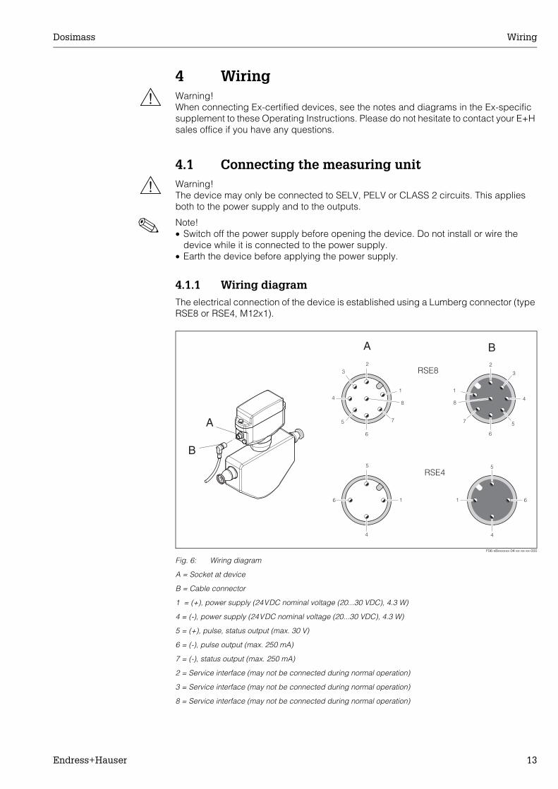
4.1.1 Wiring diagramThe electrical connection of the device is established using a Lumberg connector (type RSE8 or RSE4, M12x1).
F06-xBxxxxxx-04-xx-xx-xx-000
Fig. 6: Wiring diagram
A = Socket at device
B = Cable connector
1 = (+), power supply (24VDC nominal voltage (20...30 VDC), 4.3 W)
4 = (-), power supply (24VDC nominal voltage (20...30 VDC), 4.3 W)
5 = (+), pulse, status output (max. 30 V)
6 = (-), pulse output (max. 250 mA)
7 = (-), status output (max. 250 mA)
2 = Service interface (may not be connected during normal operation)
3 = Service interface (may not be connected during normal operation)
8 = Service interface (may not be connected during normal operation)
A
A
1
23
4
5
6
7
8
1
5
4
6
RSE4
1
2
3
4
5
6
7
8
1
5
4
6
B
B
RSE8

Wiring Dosimass
14 Endress+Hauser
4.1.2 Ground connectionThe ground connection is established via a cable lug.
F06-xBxxxxxx-04-xx-xx-xx-001
Fig. 7: Dosimass ground connection
4.1.3 Cable specificationEvery suitable cable with a temperature specification at least 20 °C higher than the ambient temperature in the application. We recommend you use a cable with a temperature specification of +80 °C.

Dosimass Wiring
Endress+Hauser 15
4.1.4 Connection examples
Eight-pin version
F06-8BExxxxx-04-xx-xx-xx-001
Fig. 8: Connection example (eight-pin version)
a PELV or SELV power supplyb Housing
Four-pin version
F06-8BExxxxx-04-xx-xx-xx-000
Fig. 9: Connection example (four-pin version)
a PELV or SELV power supplyb Housing
+
-
=
PE
a
1
4
5
6
7
b
+
-
=
PE
a
1
4
5
6
7

Wiring Dosimass
16 Endress+Hauser
4.2 Potential equalisationNo special measures are necessary for potential equalisation.
! Note! For devices for the Ex area, see the notes in the Ex-specific supplement to these Operating Instructions.
4.3 Degree of protectionThe devices fulfil all the requirements for IP 67.
Compliance with the following points is mandatory following installation in the field or servicing, in order to ensure that IP 67 protection is maintained:• The housing seals must be clean and undamaged when inserted into their grooves.
The seals must be dried, cleaned or replaced if necessary.• All threaded fasteners and screw covers must be firmly tightened.
4.4 Post-connection checkPerform the following checks after completing electrical installation of the measuring device:
Device condition and specifications Notes
Is the device damaged (visual inspection)? -
Electrical connection Notes
Does the supply voltage match the specifications on the nameplate? 24VDC nominal voltage (20...30VDC)
Do the cables have adequate strain relief? -
Is the cable type route completely isolated?Without loops and crossovers?
-
Are the power supply and signal cables correctly connected? -
Is the housing cover installed and firmly tightened? -

Dosimass Operation
Endress+Hauser 17
5 Operation
5.1 FieldTool operating programThe Dosimass flow measuring device is operated via the “FieldTool” operating program. FieldTool is a universal service and configuration software package from Endress+Hauser. Connection is by means of the PROline service interface (service connector) with a Commubox FXA 193.
! Note! You can find more information on FieldTool and how it is operated in the appropriate on-line help.
The functionality of FieldTool includes the following:• Configuration of device functions• Visualisation of measuring values (including data logging)• Data backup of device parameters• Measuring-point documentation

Operation Dosimass
18 Endress+Hauser
5.2 Structure of the function matrix
Function group Function
MEASURING VALUES
(Page 46)
MASS FLOW
(Page 46)
VOLUME FLOW
(Page 46)
DENSITY
(Page 46)
TEMPERATURE
(Page 46)
SYSTEM UNITS
(Page 47)
UNIT MASS FLOW
(Page 47)
UNIT MASS
(Page 47)
UNIT VOL. FLOW
(Page 47)
UNIT VOLUME
(Page 48)
UNIT DENSITY
(Page 48)
UNIT TEMPERATURE
(Page 48)
PULSE OUTPUT
(Page 49)
ASSIGN PULSE
(Page 49)
PULSE VALUE
(Page 49)
PULSE WIDTH
(Page 49)
OUTPUT SIGNAL
(Page 50)
FAILSAFE MODE
(Page 50)
STATUS OUTPUT
(Page 51)
ASSIGN STATUS
(Page 51)
ACTUAL STATUS
(Page 51)
COMMUNICATION
(Page 51)
TAG NAME
(Page 51)
PROCESS PARAMETER
(Page 52)
ASSIGN LOW-FLOW CUTOFF
(Page 52)
ON-VAL. LOW-FLOW CUTOFF
(Page 52)
PRESS. SHOCK SUPPRESSION
(Page 53)
EPD VALUE LOW
(Page 53)
EPD RESPONSE TIME
(Page 54)
ZERO ADJUST.
(Page 54)
ZERO POINT
(Page 54)
SYSTEM PARAMETER
(Page 55)
INSTALL. DIRECT. SENSOR(Page 55)
FLOW DAMPING
(Page 55)
SENSOR PARAMETER
(Page 56)
K-FACTOR
(Page 56)
ZEROPOINT
(Page 56)
NOMINAL DIAMETER(Page 56)
C0
(Page 56)
C1
(Page 56)
C2
(Page 56)
C3
(Page 56)
C4
(Page 56)
C5
(Page 56)
MIN.TEMP. MEAS.
(Page 56)
MAX.TEMP. MEAS.
(Page 56)
SUPERVISION
(Page 57)
ACT. SYS. COND
(Page 57)
PREV. SYS. COND
(Page 57)
ALARM DELAY
(Page 57)
SYSTEM RESET
(Page 57)
SIMULATION SYSTEM
(Page 58)
SIM. MEASURAND
(Page 58)
VALUE SIM. MEAS.
(Page 58) continued on next page

Dosimass Operation
Endress+Hauser 19
5.2.1 General notesThe function matrix comprises a multiplicity of functions which, for the sake of clarity, are arranged in a number of function groups.
! Note! • The transmitter continues to measure while data entry is in progress, i.e. the current
measured values are output via the signal outputs in the normal way.• If the supply voltage fails, all preset and configured values remain safely stored in the
EEPROM.
" Caution! Changing certain parameters such as all sensor characteristics, for example, influences numerous functions of the entire measuring system, particularly measuring accuracy.Such parameters normally may not be altered and are thus protected. Please contact Endress+Hauser if you have any questions.
Function group Function
SENSOR VERSION
(Page 58)
SERIAL NUMBER
(Page 58)
SENSOR TYPE
(Page 58)
SW REV. DAT
(Page 58)
AMPLIFIER VERSION(Page 58)
SW REV. AMP.
(Page 58)

Commissioning Dosimass
20 Endress+Hauser
6 Commissioning
6.1 Function checkMake sure that all final checks have been completed before you start up your measuring point:• Checklist for “Post-installation check” → Page 12• Checklist for “Post-connection check” → Page 16
6.2 Switching on the measuring deviceOnce the function checks have been successfully completed, it is time to switch on the supply voltage. The device is now operational.The measuring device performs a number of power on self-tests. Normal measuring mode commences as soon as start-up completes.
! Note! If start-up fails, an error message indicating the cause is displayed in the FieldTool operating program.
6.3 Zero point adjustmentAll Dosimass measuring devices are calibrated with state-of-the-art technology. The zero point obtained in this way is printed on the nameplate. Calibration takes place under reference operating conditions (→ Page 35). Consequently, zero point adjustment is generally not necessary for Dosimass!
Experience shows that the zero point adjustment is advisable only in special cases:• To achieve highest measuring accuracy also with very small flow rates.• Under extreme process or operating conditions (e.g. very high process temperatures
or very high-viscosity fluids).

Dosimass Commissioning
Endress+Hauser 21
6.3.1 Preconditions for a zero point adjustmentNote the following before you perform a zero point adjustment:• A zero point adjustment can be performed only with fluids that contain no gas or solid
contents.• A zero point adjustment is performed with the measuring tubes completely filled and
at zero flow (v = 0 m/s). This can be achieved, for example, with shut-off valves upstream and/or downstream of the sensor or by using existing valves and gates (→ Fig. 10).– Normal operation → valves 1 and 2 open– Zero point adjustment with pump pressure → valve 1 open / valve 2 closed– Zero point adjustment without pump pressure → valve 1 closed / valve 2 open
F06-8BExxxxx-11-00-00-xx-001
Fig. 10: Zero point adjustment and shut-off valves
6.3.2 Performing a zero point adjustment1. Operate the system until operating conditions have settled.
2. Stop the flow (v = 0 m/s).
3. Check the shut-off valves for leaks.
4. Check that operating pressure is correct.
5. Now perform the calibration via the "ZERO POINT ADJUST." function (→ Page 54).
1
2

Maintenance Dosimass
22 Endress+Hauser
7 MaintenanceNo special maintenance work is required.
Exterior cleaningWhen cleaning the exterior of measuring devices, always use cleaning agents that do not attack the surface of the housing and the seals.
SealsThe seals should be replaced periodically especially if moulded seals are used (aseptic version)! The period between changes depends on the frequency of the cleaning cycles and the fluid and cleaning temperature.
Dosimass Accessories/spare parts
Endress+Hauser 23
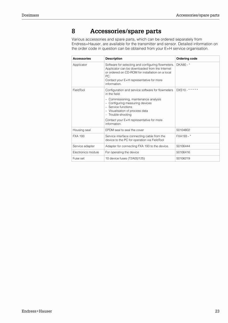
8 Accessories/spare partsVarious accessories and spare parts, which can be ordered separately from Endress+Hauser, are available for the transmitter and sensor. Detailed information on the order code in question can be obtained from your E+H service organisation.
Accessories Description Ordering code
Applicator Software for selecting and configuring flowmeters.Applicator can be downloaded from the Internet or ordered on CD-ROM for installation on a local PC.Contact your E+H representative for more information.
DKA80 - *
FieldTool Configuration and service software for flowmeters in the field:
– Commissioning, maintenance analysis– Configuring measuring devices– Service functions– Visualisation of process data– Trouble-shooting
Contact your E+H representative for more information.
DXS10 - * * * * *
Housing seal EPDM seal to seal the cover 50104802
FXA 193 Service interface connecting cable from the device to the PC for operation via FieldTool
FXA193 - *
Service adapter Adapter for connecting FXA 193 to the device. 50106444
Electronics module For operating the device 50106416
Fuse set 10 device fuses (T2A00/125) 50106219

Trouble-shooting Dosimass
24 Endress+Hauser
9 Trouble-shooting
9.1 Trouble-shooting instructionsFault conditions that arise during operation are immediately identified by Dosimass and signalled and output in different ways:
• Via a light-emitting diode (LED) on the electronics (→ Page 25)• Via the status output (→ Page 30)• Via error messages in the "FieldTool" operating program:
System error messages (→ Page 26)Process error messages (→ Page 28
9.2 Types of error
9.2.1 Type of errorErrors that occur during commissioning or measuring are signalled and/or displayed immediately. If two or more system or process errors occur, the error with the highest priority is the one shown on the display.
The measuring system distinguishes between two types of error:• System error: This group includes all device errors, for example communication
errors, hardware errors, etc. → Page 26• Process error: This group includes all application errors, for example partially filled
pipes. → Page 28
! Note! System and process errors are only differentiated in detail in the FieldTool operating program but not by error signalising via the LED or the status output.
9.2.2 Error message typesWhen system/process errors occur, the measuring system also differentiates between fault or notice messages. Serious system errors, e.g. module defects, are always identified and signalled as “fault messages” by the measuring device.
Notice message:• Display:
– LED flashes red/green alternately (approx. once a second)– FieldTool operating program: display via SN or PN (N = Notice)
• The error in question has no impact on the pulse output of the device.
Fault message:• Display:
– LED flashes red (approx. three times a second)– FieldTool operating program: display via SF or PF (F = Error, Fault)
• The response of the pulse output can be defined by means of the relevant function in the function matrix.
! Note! • Fault and notice messages are differentiated during fault diagnosis via the LED and
in the FieldTool operating program but not by the status output.• For security reasons, error messages should be output via the status output.

Dosimass Trouble-shooting
Endress+Hauser 25
9.3 Fault diagnosis via the light emitting diode (LED)There is a light-emitting diode (LED) on the electronics board by means of which easy fault diagnosis is always possible. This kind of error signalling is particularly important in the following instances:
• If the status output was not configured for outputting errors or notices.• If fault diagnosis is no longer possible via the FieldTool operating program.
# Warning! This kind of fault diagnosis is not possible in Ex-areas since the electronics compartment can only be opened if no voltage is being supplied to the device.
F06-8BExxxxx-16-xx-xx-xx-000
Fig. 11: Fault diagnosis with Dosimass using light emitting diode (LED)
Status of light-emitting diode (LED) Status of measuring system
LED lights up green Measuring system OK, low flow cutoff is active
LED flashes green (once a second) Measuring system OK, operation
LED does not light up Measuring system no longer working
LED flashes red (three times a second) – Operation not possible– Error (fault message) pending
LED flashes red/green (once a second) – Operation possible but may be restricted by application conditions.
– Notice message pending
LED flashes red/green (three times a second)
Zero point adjustment running

Trouble-shooting Dosimass
26 Endress+Hauser
9.4 System error messages (FieldTool)Serious system errors are always recognised by the device as “Fault messages” (SF = System Fault message) and displayed appropriately in the FieldTool operating program.On the other hand, simulations are only classed and displayed as notice messages (SN = System Notice message).
" Caution! In the event of a serious fault, a flowmeter might have to be returned to the manufacturer for repair. The procedures on Page 6 must be carried out before you return the device to Endress+Hauser. Always enclose a duly completed "Declaration of contamination" form. You will find a preprinted form at the back of this manual.
Type No./error message Cause Remedy / spare part
S = System errorF = Fault message (with an impact on the pulse output)N = Notice (without an impact on the pulse output)
System error - fault messages (LED = red, flashes quickly)
SF # 011AMP HW EEPROM
Electronics module:Defective EEPROM
Replace electronics module (→ Page 31). Spare parts: Page 23
SF # 012AMP SW EEPROM
Electronics module:Error accessing EEPROM data
The EEPROM data blocks in which an error has occurred are displayed in the “RESTORE DATA FAILURE” function.Faulty parameters are then replaced by predefined default values.
SF # 031HW DAT
Sensor DAT:
1. DAT is defective.
2. DAT is not plugged in or is missing.
1. Replace DAT.Spare parts: Page 23Check the spare part set number to ensure that the new, replacement DAT is compatible with the measuring electronics.
2. Insert DAT: → Page 31
SF # 032SW DAT
Sensor:Error accessing the calibration values stored in the DAT.
1. Check whether the DAT is correctly plugged in → Page 31
2. Replace DAT. Spare parts Page 23. Before replacing the DAT, check that the new, replacement DAT is compatible with the measuring electronics. Check the:– Spare part set number– Hardware revision code
3. Replace the electronics module if necessary (→ Page 31).Spare parts: Page 23
SF # 359PULSE RANGE
Pulse output:Pulse output frequency is out of range.
1. Increase the setting for pulse value.
2. Reduce flow
SF # 379LOWER FREQUENCY-LIMIT
The measuring tube oscillation frequency is below the permitted range.
Causes:– Damaged measuring tube– Sensor defective or damaged
Contact your E+H service organisation.

Dosimass Trouble-shooting
Endress+Hauser 27
SF # 380UPPER FREQUENCY-LIMIT
The measuring tube oscillation frequency is above the permitted range.
Causes:– Damaged measuring tube– Sensor defective or damaged
Contact your E+H service organisation.
SF # 381LOWER MEAS. TUBE TEMPERATURE LIMIT
The temperature sensor on the measuring tube is likely defective.
Check whether the plug of the sensor signal cable is correctly inserted into the electronics module before contacting your local E+H service organisation (→ Page 31)SF # 382
UPPER MEAS. TUBE TEMPERATURE LIMIT
SF # 385INLET SENSOR DEFECTIVE
The sensor coil on the inlet side is probably defective.
Check whether the plug of the sensor signal cable is correctly inserted into the electronics module before contacting your local E+H service organisation (→ Page 31)
SF # 386OUTLET SENSOR DEFECTIVE
The sensor coil on the outlet side is probably defective.
Check whether the plug of the sensor signal cable is correctly inserted into the electronics module before contacting your local E+H service organisation (→ Page 31)
SF # 387SENSORS ASYMMETRICAL
One of the sensor coils (inlet or outlet) is probably defective.
Check whether the plug of the sensor signal cable is correctly inserted into the electronics module before contacting your local E+H service organisation (→ Page 31)
SF # 388NOISE LIMIT CH2
The electronics module is probably defective.
Replace the electronics module (→ Page 31).
SF # 389NOISE LIMIT CH3
The electronics module is probably defective.
Replace the electronics module → Page 31
SF # 390COMMUNICATION DSP
The electronics module is probably defective.
Replace the electronics module → Page 31
System error - notice messages (LED = red/green, flashes slowly)
SN # 692SIMULATION MEASURAND
Simulation of a measured variable active (e.g. mass flow)
Switch off simulation
Type No./error message Cause Remedy / spare part

Trouble-shooting Dosimass
28 Endress+Hauser
9.5 Process error messages (FieldTool)
Type No./error message Cause Remedy / spare part
P = Process errorF = Fault message (with an impact on the pulse output)N = Notice (without an impact on the pulse output)
Process error - fault messages (LED = red, flashes quickly)
PF # 586OSCILLATION AMPLITUDE LIMIT
The fluid properties do not allow a continuation of the measurement.
Causes:– Extremely high viscosity– Process fluid is very
inhomogeneous (gas or solid content)
Change or improve process conditions.
PF # 587MEASURING TUBES NOT OSCILLATING
Extreme process conditions exist. The measuring system can therefore not be started.
Change or improve process conditions.
Process error - notice messages (LED = red/green, flashes slowly)
PN # 700EMPTY PIPE
The density is below the lower limit value set in the "EPD" function.
Causes:– Air in the measuring tube– Change or improve process
conditions.
1. Ensure that there is no gas content in the process liquid.
2. Adapt the values in the "EPD RESPONSE TIME" function to the current process conditions.
PN # 701EXCITING CURRENT LIMIT
The maximum current value for the measuring tube exciter coils has been reached, since certain process fluid characteristics are extreme, e.g. high gas or solid content.
The instrument continues to work correctly.
In particular with outgassing fluids and/or increased gas content, the following measures are recommended to increase system pressure:
1. Mount the instrument on the pressure side of a pump.
2. Mount the instrument at the lowest point of an ascending pipeline.
3. Install a valve or orifice plate downstream from the measuring device.
PN # 702FLUID INHOMOGENEOUS
Frequency control is not stable due to inhomogeneous fluid properties e.g. gas or solid content.
In particular with outgassing fluids and/or increased gas content, the following measures are recommended to increase system pressure:
1. Mount the instrument on the pressure side of a pump.
2. Mount the instrument at the lowest point of an ascending pipeline.
3. Install a valve or orifice plate downstream from the measuring device.
PN # 704NOISE LIMIT CH1
Overdriving of the internal analog to digital converter.
Causes:– Cavitation– Extreme pressure pulses– High gas flow velocity
A continuation of the measurement is still possible!
Change or improve process conditions, e.g. by reducing the flow velocity.
PN # 704NOISE LIMIT CH1

Dosimass Trouble-shooting
Endress+Hauser 29
9.6 Process errors without message
PN # 705FLOW LIMIT
The mass flow is too high. The electronics' measuring range is exceeded.
Reduce flow
PN # 731ZERO ADJUST NOT POSSIBLE
Zero point is not possible or has been cancelled.
Make sure that zero point adjustment is carried out at "zero flow" only (v = 0 m/s) (→ Page 20).
Symptoms Rectification
Measured value reading shown on display, even though the fluid is at a standstill and the measuring tube is full.
1. Check the fluid for presence of gas bubbles.
2. Activate the “ON-VAL. LF-CUTOFF” function, i.e. enter or increase value for the switch point (→ Page 52).
The fault cannot be rectified or some other fault not described above has occurred.In these instances, please contact your E+H service organisation.
The following options are available for tackling problems of this nature:
Request the services of an E+H service technicianIf you contact our service organisation to have a service technician sent out, please be ready with the following information:– Brief description of the fault– Nameplate specifications (→ Page 7): Order code and serial
number
Returning devices to E+HThe procedures on Page 6 must be carried out before you return a flowmeter requiring repair or calibration to Endress+Hauser. Always enclose a duly completed “Declaration of contamination” form with the flowmeter. You will find a preprinted “Declaration of contamination” form at the back of this manual.
Replace transmitter electronicsElectronics module defective → order spare part → Page 23
Type No./error message Cause Remedy / spare part

Trouble-shooting Dosimass
30 Endress+Hauser
9.7 Response of outputs to errors
9.8 Spare partsChap. 9.1 Page 24 ff. contains a detailed trouble-shooting guide. The measuring device, moreover, provides additional support in the form of continuous self-diagnosis and error messages.Fault rectification can entail replacing defective components with tested spare parts. An overview is provided on Page 23.
Failsafe mode of pulse and status output
Output Failsafe mode
Pulse output ! Note! The failsafe mode of the pulse output can be configured differently with the aid of the FieldTool operating program (→ Page 50):
FALLBACK VALUESignal output → no pulses
ACTUAL VALUEFault is ignored, i.e. normal measured value output on the basis of ongoing flow measurement.
" Caution! Notice messages do not have any impact on the pulse output! See the information on Page 26
Status output ! Note! The assignment of the status output can be defined via the FieldTool operating program (→ Page 51).
In the event of a fault or notice or if the power supply fails → status output not conducting

Dosimass Trouble-shooting
Endress+Hauser 31
9.9 Installing/removing the electronics
# Warning! Risk of damaging Electronics components (ESD protection). Static electricity can damage Electronics components or impair their operability. Use a workplace with a grounded working surface purposely built for electrostatically sensitive devices!
1. Switch off power supply.
2. Loosen hexagonal-headed bolt (1) and remove electronics cover (2).
3. Disconnect cable connectors from the electronics boards:– Plug of the sensor signal cable (3) incl. DAT (4)– Plug of the exciting current cable (5)– Plug for power supply and signal outputs (6)
4. Loosen Phillips screws (7) and remove Electronics module (8).
5. Installation is the reverse of the removal procedure.
" Caution! Use only original Endress+Hauser parts.
F06-8BExxxxx-03-06-06-xx-000
Fig. 12: Installing and removing the electronics
1 Hexagonal-headed bolt (AF 10)2 Electronics compartment cover3 Plug of the sensor signal cable4 DAT (sensor and measuring point memory)5 Plug of the exciting current cable6 Cable connector for power supply/pulse output/status output7 Phillips screw8 Electronics module9 Socket for device connection
34
56
2 3
5
4
6
8
1
7
9
9

Trouble-shooting Dosimass
32 Endress+Hauser
9.10 Replacing the device fuse1. Switch off power supply.
2. Remove the electronics module (→ Page 31).
3. Replace the fuse (1) with a pincers.
4. Installation is the reverse of the removal procedure.
" Caution! Use only original Endress+Hauser parts.
F06-8BExxxxx-03-xx-06-xx-001
Fig. 13: Replacing the device fuse on the electronics.
1 Device fuse
9.11 Software history
9.12 ReturnPlease comply with the instructions on Page 6.
9.13 DisposalObserve the regulations applicable in your country or region.
E+H FLOWTEC AG 321642-0200 A
1
1
Software version / date Changes to software DocumentationChanges, amendments
V1.00.00/01.12.2003 Original software
Compatible with FieldTool:
-

Dosimass Technical data
Endress+Hauser 33
10 Technical data
10.1 Technical data at a glance
10.1.1 ApplicationThe measuring device is for measuring the mass flow and volume flow of liquids in sealed piping systems. Fluids with widely differing properties can be measured, for example:
• Additives• Oils, fats• Acids, alkalis• Varnishes, paints• Suspensions
10.1.2 Function and system design
Measuring principle Mass flow measurement by the Coriolis principle
Measuring system The measuring system comprises a compact unit consisting of a sensor and transmitter.
10.1.3 Input
Measured variable • Mass flow• Volume flow (calculated from mass flow and density)• Density• Fluid temperature (measured with temperature sensors)
Measuring range
Recommended full scale values:See details on Page 37, (“Limiting flow”)
Operable flow range Greater than 1000 :1. Flows above the preset full scale value do not overload the amplifier, i.e. totalizer values are registered correctly.
DN Range of full scale values (liquids)mmin...mmax
81525
0... 2000 kg/h0... 6500 kg/h0...18000 kg/h

Technical data Dosimass
34 Endress+Hauser
10.1.4 Output
Output signal Pulse output:Passive, max. 30VDC/250mA, pulse value and pulse polarity can be selected, pulse width adjustable (0.05 ms ... 1 s).
! Note! The device may only be connected to SELV, PELV or CLASS 2 circuits.
Signal on alarm Pulse output → behaviour can be selectedTransistor status output not conducting in the event of a fault/notice (depending on setting) or if the power supply fails
Switching output Status output:Passive, max. 30 VDC / 250 mA
! Note! The device may only be connected to SELV, PELV or CLASS 2 circuits.
Low flow cutoff Switch point for low flow cutoff selectable.
Galvanic isolation The power supply and outputs are galvanically isolated from one another.
10.1.5 Power supply
Electrical connections See Page 17 ff.
Supply voltage 24VDC nominal voltage (20...30 VDC)
! Note! • The power supply may not exceed a maximum short-circuit current of 50 A.• The device may only be connected to SELV, PELV or CLASS 2 circuits.
Potential equalisation No special measures are necessary for potential equalisation. For devices for the Ex area, see the notes in the Ex-specific supplement to these Operating Instructions.
Cable connection Lumberg plug (RSE8 or RSE4, M12x1) for power supply and signal outputs
Cable specification Every suitable cable with a temperature specification at least 20 °C higher than the ambient temperature in the application. We recommend you use a cable with a temperature specification of +80 °C.
Power consumption Max. 4.3 WSwitch-on current: max. 1A (< 6 ms)
Power supply failure Lasting min. 20 ms.:All sensor and measuring point data remain in the DAT

Dosimass Technical data
Endress+Hauser 35
10.1.6 Performance characteristics
Reference operating conditions
Error limits following ISO/DIS 11631:
• 20...30 °C; 2...4 bar• Calibration systems traced to national norms. • Zero point calibrated under operating conditions• Density calibration performed
Max. measured error Mass flow:±0.15% o.r. (1...4 m/s)or ±0.3% ± [(zero point stability / measured value) x 100]% o.r.or ±5% ± [(zero point stability / measured value) x 100]% o.r.
o.r. = of reading
Zero point stability:
Calculation example:Give that: Dosimass DN 15, flow = 1300 kg/h, measured error: ±0.3% ± [(zero point stability / measured value) x 100]% o.r.
Measured error →
Repeatability
Influence of medium temperature
When there is a difference between the temperature for zero point adjustment and the process temperature, the typical measured error of the Promass sensor is ±0.0003% of the full scale value / °C.
Influence of medium pressure
The effect of a difference in pressure between the calibration pressure and the process pressure on the measured error for mass flow is negligible.
DN Maximum full scale value[kg/h]
Zero point stability[kg/h]
8 2000 0.20
15 6500 0.65
25 18000 1.8
35,0%100hkg1300
hkg65,0%3,0 �����
Dosing time [s]
Standard deviation [%]
Confidence limit of the mean
3s = 99.7% [%]
≥ 0.75 0.2 ± 0.6
≥ 1.5 0.1 ± 0.3
≥ 3.0 0.05 ± 0.15

Technical data Dosimass
36 Endress+Hauser
10.1.7 Operating conditions: Installation
Installation instructions Page 8 ff.
Inlet and outlet runs There are no installation requirements regarding inlet and outlet runs.
System pressure Page 10
10.1.8 Operating conditions: Environment
Ambient temperature range
-20...+60 °C (sensor, transmitter)Install the device at a shady location. Avoid direct sunlight, particularly in warm climatic regions.
Storage temperature -40...+80 °C (preferably +20 °C)
Degree of protection Standard: IP 67 (NEMA 4X) for transmitter and sensor
Shock resistance In accordance with IEC 68-2-31

Dosimass Technical data
Endress+Hauser 37
10.1.9 Operating conditions: Process
Medium temperature range
Sensor:• -40...+125 °C
Seals:• No internal seals
Medium pressure range Max. 100bar, depending on process connection
Limiting flow See information on Page 33, ("Measuring range")
Select nominal diameter by optimising between required flow range and permissible pressure loss. See Page 33, "Measuring range," for a list of maximum possible full scale values.• The minimum recommended full scale value is approx. 1/20 of the maximum full scale
value.• In most applications, 20...50% of the maximum full scale value can be considered
ideal.• Select a lower full scale value for abrasive substances such as fluids with entrained
solids (flow velocity < 1 m/s).

Technical data Dosimass
38 Endress+Hauser
Pressure loss Pressure loss depends on the fluid properties and on its flow rate. The following formulas can be used to approximately calculate the pressure loss:
Pressure loss coefficients:
F06-8BExxxxx-05-xx-xx-xx-001
Fig. 14: Pressure loss diagram for water
Reynolds number
Re ≥ 2300
Re < 2300
∆p = pressure loss [mbar]υ = kinematic viscosity [m2/s]g = mass flow [kg/s]
ρ = density [kg/m3]d = inside diameter of measuring tubes [m]K...K2 = constants (depending on nominal diameter)
DN d [m] K K1 K2
8 5.35 ⋅ 10-3 5.70 ⋅ 107 7.91 ⋅ 107 2.10 ⋅ 107
15 8.30 ⋅ 10-3 7.62 ⋅ 106 1.73 ⋅ 107 2.13 ⋅ 106
25 12.00 ⋅ 10-3 1.89 ⋅ 106 4.66 ⋅ 106 6.11 ⋅ 105
Pressure loss data including interface between measuring tubes and piping
�� �����
d
m2Re
�
86.085.125.0 mKp ���� ��� �
�� ��� ���
225.0 m2Km1Kp
��
DN 25
DN 8
10000
1000
100
10
1
0.10.001 0.01 0.1 1 10 100 1000
DN 15
[mbar]
[t/h]

Dosimass Technical data
Endress+Hauser 39
10.1.10 Mechanical construction
Design / dimensions → Page 41 ff.
Weight
Material Transmitter housing:1.4308/304
Sensor housing:Acid and alkali-resistant outer surface; stainless steel 1.4301/304
Process connection:• Threaded joint DIN 11864-1 → stainless steel 1.4404/316L• Sanitary connection DIN 11851 / SMS 1145 → stainless steel 1.4404/316L• Threaded joint ISO 2853 / DIN 11864-1 → stainless steel 1.4404/316L• Tri-Clamp → stainless steel 1.4404/316L
Measuring pipes:Stainless steel 1.4539/904L
Seals:Welded process connections without internal seals
Material load diagram The material load curves (pressure-temperature diagrams) for the process connections are to be found in the following documents:Technical Information Dosimass (TI 065D/06/en)
Process connection Sanitary connections: Tri-Clamp, threaded joints (DIN 11851, SMS 1145, ISO 2853, DIN 11864-1)
10.1.11 User interface
Display elements Dosimass does not have a display or display elements.
Remote operation Operation takes place via the "FieldTool" configuration and service program from Endress+Hauser. This can be used to configure functions and read off measured values.
Dosimass / DN 8 15 25
Weight in [kg] 3.5 4.0 4.5

Technical data Dosimass
40 Endress+Hauser
10.1.12 Certificates and approvals
Ex approval Information about currently available Ex versions (ATEX, FM, CSA etc.) can be supplied by your E+H Sales Centre on request. All explosion protection data are given in a separate documentation which is available upon request.
Sanitary compatibility 3A approval
Pressure measuring device approval
All Dosimass devices correspond to Article 3(3) of the EC Directive 97/23/EC (Pressure Equipment Directive) and have been designed and manufactured according to good engineering practice.
CE mark The measuring system is in conformity with the statutory requirements of the EC Directives. Endress+Hauser confirms successful testing of the device by affixing to it the CE mark.
Other standards and guidelines
EN 60529:Degrees of protection by housing (IP code)
EN 61010-1:Protection Measures for Electrical Equipment for Measurement, Control, Regulation and Laboratory Procedures.
EN 61326 (IEC 1326):Electromagnetic compatibility (EMC requirements)
EN 61000-4-3 (IEC 1000-4-3)Operating behaviour A with shielded connecting cable possible (shield placed as short as possible on both sides), otherwise operating behaviour B.
NAMUR NE 21:Association for Standards for Control and Regulation in the Chemical Industry
10.1.13 Ordering information
The E+H service organisation can provide detailed ordering information and information on specific order codes on request.
10.1.14 Accessories/spare parts
Page 23
10.1.15 Supplementary Documentation
❑Technical Information Dosimass (TI 065D/06/en)❑Supplementary documentation on Ex-ratings: ATEX

Dosimass Technical data
Endress+Hauser 41
10.2 Dimensions
10.2.1 Dosimass dimensions: Tri-Clamp connections
F06-8BExxxxx-06-00-xx-xx-003
Fig. 15: Dosimass dimensions: Tri-Clamp connections
G U
di
CB
A
L+1.5–2.0
14654
54
1/2" Tri-Clamp: 1.4404/316L
DN Clamp A B C G L U di
8 1/2" 253 160 93 25.0 229 9.5 5.35
15 1/2" 267 167 105 25.0 273 9.5 8.30
3A version also available (Ra ≤0.8 µm/150 grit)
3/4" Tri-Clamp: 1.4404/316L
DN Clamp A B C G L U di
8 3/4" 253 160 93 25.0 229 16 5.35
15 3/4" 267 167 105 25.0 273 16 8.30
3A version also available (Ra ≤0.8 µm/150 grit)
1" Tri-Clamp: 1.4404/316L
DN Clamp A B C G L U di
8 1" 253 160 93 50.4 229 22.1 5.35
15 1" 267 162 105 50.4 273 22.1 8.30
25 1" 273 167 106 50.4 324 22.1 12.00
3A version also available (Ra ≤0.8 µm/150 grit)

Technical data Dosimass
42 Endress+Hauser
10.2.2 Dosimass dimensions: DIN 11851 connections (sanitary connection)
F06-8BExxxxx-06-00-xx-xx-001
Fig. 16: Dosimass dimensions : DIN 11851 connections (sanitary connection)
G U
L+1.5–2.0
CB
A
146
di
54
54
Sanitary connection DIN 11851: 1.4404/316L
DN A B C G L U di
8 253 160 93 Rd 34 x 1/8" 229 16 5.35
15 267 162 105 Rd 34 x 1/8" 273 16 8.30
25 273 167 106 Rd 52 x 1/6" 324 26 12.00
3A version also available (Ra ≤0.8 µm/150 grit)
Dosimass Technical data
Endress+Hauser 43
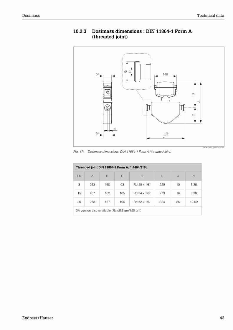
10.2.3 Dosimass dimensions : DIN 11864-1 Form A (threaded joint)
F06-8BExxxxx-06-00-xx-xx-004
Fig. 17: Dosimass dimensions: DIN 11864-1 Form A (threaded joint)
G Udi
L+1.5–2.0
CB
A
54
54
146
Threaded joint DIN 11864-1 Form A: 1.4404/316L
DN A B C G L U di
8 253 160 93 Rd 28 x 1/8" 229 10 5.35
15 267 162 105 Rd 34 x 1/8" 273 16 8.30
25 273 167 106 Rd 52 x 1/6" 324 26 12.00
3A version also available (Ra ≤0.8 µm/150 grit)

Technical data Dosimass
44 Endress+Hauser
10.2.4 Dosimass dimensions : ISO 2853 connections (threaded joint)
F06-8BExxxxx-06-00-xx-xx-006
Fig. 18: Dosimass dimensions: ISO 2853 connections (threaded joint)
G U
di
L+1.5–2.0
CB
A
14654
54
Threaded joint ISO 2853: 1.4404/316L
DN A B C G1) L U di
8 253 160 93 37.13 229 22.6 5.35
15 267 162 105 37.13 273 22.6 8.30
25 273 167 106 37.13 324 22.6 12.00
1) Max. thread diameter to ISO 2853 Annex A, 3A version also available (Ra ≤0.8 µm/150 grit)

Dosimass Technical data
Endress+Hauser 45
10.2.5 Dosimass dimensions: SMS 1145 connections (sanitary connection)
F06-8BExxxxx-06-00-xx-xx-002
Fig. 19: Dosimass dimensions : SMS 1145 connections (sanitary connection)
G Udi
L+1.5–2.0
CB
A
14654
54
Sanitary connection SMS 1145: 1.4404/316L
DN A B C G L U di
8 253 160 93 Rd 40 x 1/6" 229 22.5 5.35
15 267 162 105 Rd 40 x 1/6" 273 22.5 8.30
25 273 167 106 Rd 40 x 1/6" 324 22.5 12.00
3A version also available (Ra ≤0.8 µm/150 grit)
Appendix - Function description Dosimass
46 Endress+Hauser
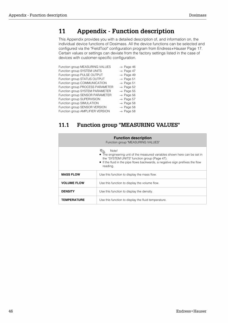
11 Appendix - Function descriptionThis Appendix provides you with a detailed description of, and information on, the individual device functions of Dosimass. All the device functions can be selected and configured via the "FieldTool" configuration program from Endress+Hauser Page 17.Certain values or settings can deviate from the factory settings listed in the case of devices with customer-specific configuration.
11.1 Function group "MEASURING VALUES"
Function group MEASURING VALUES → Page 46Function group SYSTEM UNITS → Page 47Function group PULSE OUTPUT → Page 49Function group STATUS OUTPUT → Page 51Function group COMMUNICATION → Page 51Function group PROCESS PARAMETER → Page 52Function group SYSTEM PARAMETER → Page 55Function group SENSOR PARAMETER → Page 56Function group SUPERVISION → Page 57Function group SIMULATION → Page 58Function group SENSOR VERSION → Page 58Function group AMPLIFIER VERSION → Page 58
Function descriptionFunction group "MEASURING VALUES"
! Note! • The engineering unit of the measured variables shown here can be set in
the “SYSTEM UNITS" function group (Page 47).• If the fluid in the pipe flows backwards, a negative sign prefixes the flow
reading.
MASS FLOW Use this function to display the mass flow.
VOLUME FLOW Use this function to display the volume flow.
DENSITY Use this function to display the density.
TEMPERATURE Use this function to display the fluid temperature.

Dosimass Appendix - Function description
Endress+Hauser 47
11.2 Function group "SYSTEM UNITS"
Function descriptionFunction group "SYSTEM UNITS"
UNIT MASS FLOW Use this function to select the unit for displaying the mass flow (mass/time).
Options:
Metric:gram → g/s; g/min; g/h; g/daykilogram → kg/s; kg/min; kg/h; kg/dayMetric ton → t/s; t/min; t/h; t/day
US:ounce → oz/s; oz/min; oz/h; oz/daypound → lb/s; lb/min; lb/h; lb/dayton → ton/s; ton/min; ton/h; ton/day
Factory setting:Country dependent (kg/h or lb/min)
UNIT MASS Use this function to select the unit for displaying the mass.
Options:Metric → mg; g; kg; tUS → oz; lb; ton
Factory setting:Country dependent (g or oz)
UNIT VOLUME FLOW Use this function to select the unit for the volume flow.
Options:
Metric:Cubic centimetre → cm3/s; cm3/min; cm3/h; cm3/dayCubic decimetre → dm3/s; dm3/min; dm3/h; dm3/dayCubic metre → m3/s; m3/min; m3/h; m3/dayMillilitre → ml/s; ml/min; ml/h; ml/dayLitre → l/s; l/min; l/h; l/dayHectolitre → hl/s; hl/min; hl/h; hl/dayMegalitre → Ml/s; Ml/min; Ml/h; Ml/day
US:Cubic centimeter → cc/s; cc/min; cc/h; cc/dayAcre foot → af/s; af/min; af/h; af/dayCubic foot → ft3/s; ft3/min; ft3/h; ft3/dayFluid ounce → oz f/s; oz f/min; oz f/h; oz f/dayGallon → gal/s; gal/min; gal/h; gal/dayBarrel (normal fluids: 31.5 gal/bbl) → bbl/s; bbl/min; bbl/h; bbl/dayBarrel (beer: 31.0 gal/bbl) → bbl/s; bbl/min; bbl/h; bbl/dayBarrel (petrochemicals: 42.0 gal/bbl) → bbl/s; bbl/min; bbl/h; bbl/dayBarrel (filling tanks: 55.0 gal/bbl) → bbl/s; bbl/min; bbl/h; bbl/day
Imperial:Gallon → gal/s; gal/min; gal/h; gal/dayBarrel (beer: 36.0 gal/bbl) → bbl/s; bbl/min; bbl/h; bbl/dayBarrel (petrochemicals: 42.0 gal/bbl) → bbl/s; bbl/min; bbl/h; bbl/day
Factory setting:Country dependent (l/h or USgal/min)

Appendix - Function description Dosimass
48 Endress+Hauser
UNIT VOLUME Use this function to select the unit for the volume.
Options:Metric → cm3; dm3; m3; µl; ml; l; hl; MlUS → cc; af; ft3; oz f; gal; bbl (normal fluids); bbl (beer); bbl (petrochemicals); bbl (filling tanks)Imperial → gal; bbl (beer); bbl (petrochemicals)
Factory settings:Country dependent (ml or cc)
UNIT DENSITY Use this function to select the unit for displaying the fluid density.
Options:Metric → g/cm3; g/cc; kg/dm3; kg/l; kg/m3; SD 4 °C, SD 15 °C, SD 20 °C; SG 4 °C, SG 15 °C, SG 20 °CUS → lb/ft3; lb/gal; lb/bbl (normal fluids); lb/bbl (beer); lb/bbl (petrochemicals); lb/bbl (filling tanks)Imperial → lb/gal; lb/bbl (beer); lb/bbl (petrochemicals)
SD = Specific Density, SG = Specific GravityThe specific density is the ratio of fluid density to water (at water temperature = 4, 15, 20 °C)
Factory setting:Country dependent (kg/l or g/cc)
UNIT TEMPERATURE Use this function to select the unit for displaying the temperature.
Options:°C (CELSIUS)°F (FAHRENHEIT)K (KELVIN)
Factory setting:Country dependent (°C or °F)
Function descriptionFunction group "SYSTEM UNITS"

Dosimass Appendix - Function description
Endress+Hauser 49
11.3 Function group "PULSE OUTPUT"
Function descriptionFunction group "PULSE OUTPUT"
ASSIGN PULSE Use this function to assign a measured variable to the pulse output.
Options:OFFMASS FLOWVOLUME FLOW
Factory setting:MASS FLOW
PULSE VALUE Use this function to define the flow at which a pulse is triggered. These pulses can be totalled by an external totalizer, and the total flow quantity since measuring started can be registered in this way.
Factory setting:
SI units:DN 8 → 0.02 gDN 15 → 0.10 gDN 25 → 0.20 g
US units:DN 8 → 0.001 ozDN 15 → 0.004 ozDN 25 → 0.010 oz
! Note! The appropriate unit is taken from the SYSTEM UNITS function group (→ Page 47 ff.).
PULSE WIDTH Use this function to enter the pulse width of the output pulses.
User input:0.05...1000 ms
Factory setting:0.05 ms
The pulses are always output with the pulse width (B) entered in this function. The intervals (P) between the individual pulses are automatically configured. However, they must at least correspond to the pulse width (B = P).
F06-xxxxxxxx-05-xx-xx-xx-012
B= Pulse width entered (the illustration applies to positive pulses)P= Intervals between the individual pulses
! Note! When entering the pulse width, select a value that can still be processed by an external totalizer (e.g. mechanical totalizer, PLC, etc.).
" Caution! If the pulse frequency resulting from the pulse value entered (see PULSE VALUE function on Page 49) and the current flow is too big (fmax = 1/2x1/T), to maintain the pulse width selected, a system error message is generated.
B=P
B
PP
B
B< P

Appendix - Function description Dosimass
50 Endress+Hauser
OUTPUT SIGNAL Use this function to configure the output in such a way that it for example matches an external totalizer. According to the application, the direction of the pulses can be selected here.
Options:PASSIVE-POSITIVEPASSIVE-NEGATIVE
Factory setting:PASSIVE-POSITIVE
F-xxxxxxxx-05-xx-xx-en-001
FAILSAFE MODE For reasons of safety it is advisable to ensure that the pulse output assumes a predefined state in the event of a fault. Use this function to define this state.
Options:
FALLBACK VALUEOutput is 0 pulse.
ACTUAL VALUEMeasured value output is based on the current flow measurement. The fault is ignored.
Factory setting:FALLBACK VALUE
Function descriptionFunction group "PULSE OUTPUT"
B B
PASSIVE-POSITIVEpulses
conducting conducting
nonconducting
nonconducting
t t
transistor transistor
PASSIVE-NEGATIVEpulses
B = Pulse width

Dosimass Appendix - Function description
Endress+Hauser 51
11.4 Function group "STATUS OUTPUT"
11.5 Function group "COMMUNICATION"
Function descriptionFunction group "STATUS OUTPUT"
ASSIGN STATUS Use this function to assign a switching function to the status output.
Options:NON CONDUCTIVECONDUCTIVEFAULT MESSAGEFAULT & NOTICE
Factory setting:FAULT MESSAGE
! Note! • The behaviour of the status output is of the quiescent-current type, in other
words the transistor is conductive when normal, error-free measuring is in progress.
• Please read and comply with the information on the switching characteristics of the status output (see Pages 35, 36).
ACTUAL STATUS Use this function to display the current status of the status output.
DISPLAY:NON CONDUCTIVECONDUCTIVE
Function descriptionFunction group "COMMUNICATION"
TAG NAME Use this function to assign a tag name to the measuring device.
User input:Max. 8-character text, permissible: A-Z, 0-9, +,-, punctuation marks
Factory setting:"_ _ _ _ _ _ _ _" (without text)

Appendix - Function description Dosimass
52 Endress+Hauser
11.6 Function group "PROCESS PARAMETER"
Function descriptionFunction group "PROCESS PARAMETER"
ASSIGN LOW-FLOW CUTOFF
Use this function to assign the measured variable for the low flow cutoff.
Options:MASS FLOWVOLUME FLOW
Factory setting:MASS FLOW
ON VALUE LOW-FLOW CUTOFF
For entering the on-value for low flow cutoff. Low flow cutoff is active if the setting is a value not equal to 0. Low flow cutoff works with a hysteresis of 50% (off-value = 150% of the on-value).
Factory setting:The following factory settings correspond to a flow velocity of approx. v = 0.04 m/s.
SI units:DN 8 → 8.00 kg/hDN 15 → 26.00 kg/hDN 25 → 72.00 kg/h
US units:DN 8 → 0.300 lb/minDN 15 → 1.000 lb/minDN 25 → 2.600 lb/min

Dosimass Appendix - Function description
Endress+Hauser 53
PRESSURE SHOCK SUPPRESSION
Severe liquid movement can occur briefly in the pipeline when a valve is closed. This is recorded by the measuring system. For this reason, the device is equipped with pressure shock suppression (= time-based signal suppression) which can eliminate "faults" conditioned by the system. Use this function to determine the time span of the active pressure shock suppression.
! Note! Low flow cutoff must be activated for pressure shock suppression to be used (see ON-VALUE LOW FLOW CUTOFF function on Page 52).
Activating pressure shock suppressionPressure shock suppression is activated once the flow undershoots the on-value of the low flow cutoff (see graphic, point 1).
The following applies when activating pressure shock suppression:• Pulse output → does not output any more pulses
Deactivating pressure shock suppressionPressure shock suppression is inactive once the time specified in this function has expired (see graphic, point 2).
! Note! The current flow value is not processed and displayed again until the specified time for pressure shock suppression has expired and the flow has exceeded the off-value for low flow cutoff (see graphic, point 3).
F06-xxxxxxxx-05-xx-xx-en-000
User input:Max. 4-digit number, including unit: 0...10 s
Factory setting:0 s
EPD VALUE LOW Use this function to set a lower threshold (limit value) for the measured density since problems in the process can occur if the density is too low.
Factory setting:Country dependent (SI: 0.2 kg/l; US: 0.2 g/cc)
Function descriptionFunction group "PROCESS PARAMETER"
2
3
➝ active➝ inactive ➝ inactivetime
Low flow cutoff
Pressure shock suppression
OFF-ValueON-Value
Valve closes
Flowrate
1
Given time
Appendix - Function description Dosimass
54 Endress+Hauser
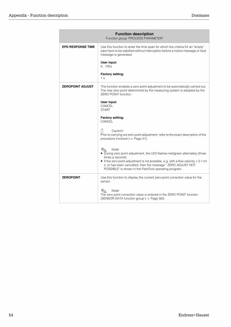
EPD RESPONSE TIME Use this function to enter the time span for which the criteria for an "empty" pipe have to be satisfied without interruption before a notice message or fault message is generated.
User input:0...100s
Factory setting:1 s
ZEROPOINT ADJUST This function enables a zero point adjustment to be automatically carried out. The new zero point determined by the measuring system is adopted by the ZERO POINT function.
User input:CANCELSTART
Factory setting:CANCEL
" Caution! Prior to carrying out zero point adjustment, refer to the exact description of the procedure involved (→ Page 21).
! Note! • During zero point adjustment, the LED flashes red/green alternately (three
times a second).• If the zero point adjustment is not possible, e.g. with a flow velocity > 0.1 m/
s, or has been cancelled, then the message " ZERO ADJUST NOT POSSIBLE" is shown in the FieldTool operating program.
ZEROPOINT Use this function to display the current zero-point correction value for the sensor.
! Note! The zero point correction value is entered in the ZERO POINT function (SENSOR DATA function group (→ Page 56))
Function descriptionFunction group "PROCESS PARAMETER"

Dosimass Appendix - Function description
Endress+Hauser 55
11.7 Function group "SYSTEM PARAMETER"
Function descriptionFunction group "SYSTEM PARAMETER"
INSTALLATION DIRECTION SENSOR
Use this function to reverse the sign of the measured variable, if necessary.
! Note! Ascertain the actual direction of fluid flow with reference to the direction indicated by the arrow on the sensor nameplate.
Options:FORWARDS (flow as indicated by the arrow on the nameplate)REVERSE (flow in the opposite direction to the arrow on the nameplate)
Factory setting:FORWARD
FLOW DAMPING For setting the time constant of flow damping. This can be used to reduce the sensitivity of the measuring signal to interference peaks (e.g. in the event of high solids content, gas pockets in the fluid, etc.). The reaction time of the measuring system increases with an increase in the time constant.
User input:0...100 s
Factory setting:0 s
! Note! The damping acts on all functions and outputs of the measuring device.

Appendix - Function description Dosimass
56 Endress+Hauser
11.8 Function group "SENSOR PARAMETER"
Function descriptionFunction group "SENSOR PARAMETER"
All sensor data, including calibration factor, zero point, nominal diameter, etc. are set at the factory. All the sensor's parameter settings are saved on the DAT memory chip.
K-FACTOR Use this function to display the current calibration factor for the sensor.
Factory setting:Depends on nominal diameter and calibration
ZEROPOINT Use this function to display and enter the current zero-point correction value for the sensor.
Factory setting:Depends on the calibration
NOMINAL DIAMETER Use this function to display the nominal diameter for the sensor.
Factory setting:Depends on the size of the sensor
C0 Use this function to display the actual density coefficient C0.
C1 Use this function to display the actual density coefficient C1.
C2 Use this function to display the actual density coefficient C2.
C3 Use this function to display the actual density coefficient C3.
C4 Use this function to display the actual density coefficient C4.
C5 Use this function to display the actual density coefficient C5.
MIN. TEMPERATURE MEAS.
Use this function to display the lowest fluid temperature measured.
MAX. TEMPERATURE MEAS.
Use this function to display the highest fluid temperature measured.

Dosimass Appendix - Function description
Endress+Hauser 57
11.9 Function group "SUPERVISION"
Function descriptionFunction group "SUPERVISION"
ACTUAL SYSTEM CONDITION
Use this function to display the current system status.
Display:"SYSTEM OK"or the fault/notice message with the highest priority.
PREVIOUS SYSTEM CONDITIONS
Use this function to display the 16 most recent fault and notice messages.
Display:The 16 most recent fault or notice messages.
PERSISTENT RECORDING
Use this function to switch persistent recording of the system conditions on or off.
Options:ONOFF
Factory setting:ON
ALARM DELAY Use this function to define a time span for which the criteria for an error have to be satisfied without interruption before an error or notice message is generated.
User input:0...10 s (in steps of one second)
Factory setting:0 s
" Caution! If this function is activated, fault and notice messages are delayed by the time corresponding to the setting before being forwarded to the higher-order controller (process controller, etc.). It is therefore imperative to check in advance in order to make sure whether a delay of this nature could affect the safety requirements of the process. If fault and notice messages cannot be suppressed, a value of 0 seconds must be entered here.
SYSTEM RESET Use this function to perform a reset of the measuring system.
Options:CANCELRESTART SYSTEM (restart without interrupting power supply)
Factory setting:CANCEL

Appendix - Function description Dosimass
58 Endress+Hauser
11.10 Function group "SIMULATION"
11.11 Function group "SENSOR VERSION"
11.12 Function group "AMPLIFIER VERSION"
Function descriptionFunction group "SIMULATION"
SIMULATION MEASURAND
Use this function to simulate a measured variable to check that the pulse output behaves correctly, for example. During this time, the words "SIMULATION MEASURAND" appear in the operating program.
Options:OFFMASS FLOWVOLUME FLOWDENSITYTEMPERATURE
Factory setting:OFF
" Caution! • The measuring device cannot be used for measuring while this simulation
is in progress.• The setting is not saved if the power supply fails.
VALUE SIMULATION MEASURAND
! Note! This function is not available unless the SIMULATION MEASURAND function was activated.
Use this function to define a selectable value (e.g. 12 kg/s). This value is used to test downstream devices and the measuring device itself.
Factory setting:0 kg/h or 0 m3/h or 0 kg/l or 0°C
" Caution! The setting is not saved if the power supply fails.
Function descriptionFunction group "SENSOR VERSION"
SERIAL NUMBER Use this function to display the serial number of the device.
SENSOR TYPE Use this function to display the sensor type.
SOFTWARE REV. DAT Use this function to display the revision number of the software used to programme the DAT.
Function descriptionFunction group "AMPLIFIER VERSION"
SOFTWARE REV. AMPLIFIER
Use this function to display the software revision number of the amplifier.

Dosimass Endress+Hauser
Endress+Hauser 59
Index
AAccessories . . . . . . . . . . . . . . . . . . . . . . . . . . . . . . . 23ACTUAL STATUS . . . . . . . . . . . . . . . . . . . . . . . . . . . 51ACTUAL SYSTEM CONDITION . . . . . . . . . . . . . . . . 57ALARM DELAY . . . . . . . . . . . . . . . . . . . . . . . . . . . . . 57Ambient temperature range . . . . . . . . . . . . . . . . . . . 36AMPLIFIER VERSION (function group). . . . . . . . . . . 58Application . . . . . . . . . . . . . . . . . . . . . . . . . . . . . . . . 33Approvals . . . . . . . . . . . . . . . . . . . . . . . . . . . . . . . 7, 40ASSIGN LOW-FLOW CUTOFF . . . . . . . . . . . . . . . . . 52ASSIGN PULSE. . . . . . . . . . . . . . . . . . . . . . . . . . . . . 49ASSIGN STATUS. . . . . . . . . . . . . . . . . . . . . . . . . . . . 51
BBrief operating instructions. . . . . . . . . . . . . . . . . . . . . 2
CC0 . . . . . . . . . . . . . . . . . . . . . . . . . . . . . . . . . . . . . . . 56C1 . . . . . . . . . . . . . . . . . . . . . . . . . . . . . . . . . . . . . . . 56C2 . . . . . . . . . . . . . . . . . . . . . . . . . . . . . . . . . . . . . . . 56C3 . . . . . . . . . . . . . . . . . . . . . . . . . . . . . . . . . . . . . . . 56C4 . . . . . . . . . . . . . . . . . . . . . . . . . . . . . . . . . . . . . . . 56C5 . . . . . . . . . . . . . . . . . . . . . . . . . . . . . . . . . . . . . . . 56Cable connection . . . . . . . . . . . . . . . . . . . . . . . . . . . 34Cable specification . . . . . . . . . . . . . . . . . . . . . . . . . . 34CE mark . . . . . . . . . . . . . . . . . . . . . . . . . . . . . . . . . . 40Certificates . . . . . . . . . . . . . . . . . . . . . . . . . . . . . . 7, 40Cleaning
Exterior cleaning . . . . . . . . . . . . . . . . . . . . . . . . . 22Commissioning
Zero point adjustment . . . . . . . . . . . . . . . . . . . . . 20COMMUNICATION (function group) . . . . . . . . . . . . 51Connection
See Electrical connection
DDegree of protection. . . . . . . . . . . . . . . . . . . . . . . . . 36DENSITY . . . . . . . . . . . . . . . . . . . . . . . . . . . . . . . . . . 46Designated use. . . . . . . . . . . . . . . . . . . . . . . . . . . . . . 5Device designation . . . . . . . . . . . . . . . . . . . . . . . . . . . 7Device fuse (replacing). . . . . . . . . . . . . . . . . . . . . . . 32Dimensions
DIN 11851 . . . . . . . . . . . . . . . . . . . . . . . . . . . . . . 42DIN 11864-1 Form A . . . . . . . . . . . . . . . . . . . . . . 43ISO 2853 . . . . . . . . . . . . . . . . . . . . . . . . . . . . . . . 44SMS 1145. . . . . . . . . . . . . . . . . . . . . . . . . . . . . . . 45Tri-Clamp connections. . . . . . . . . . . . . . . . . . . . . 41
Disposal . . . . . . . . . . . . . . . . . . . . . . . . . . . . . . . . . . 32
EElectrical connection
Cable specification . . . . . . . . . . . . . . . . . . . . . . . 14Connection examples . . . . . . . . . . . . . . . . . . . . . 15Degree of protection . . . . . . . . . . . . . . . . . . . . . . 16Ground connection . . . . . . . . . . . . . . . . . . . . . . . 14Measuring unit . . . . . . . . . . . . . . . . . . . . . . . . . . . 13Post-connection check (check list) . . . . . . . . . . . 16
Potential equalisation . . . . . . . . . . . . . . . . . . . . . . 16Wiring diagram . . . . . . . . . . . . . . . . . . . . . . . . . . . 13
Electrical connections . . . . . . . . . . . . . . . . . . . . . . . . 34Electronics (installing) . . . . . . . . . . . . . . . . . . . . . . . . 31EPD RESPONSE TIME . . . . . . . . . . . . . . . . . . . . . . . . 54EPD VALUE LOW. . . . . . . . . . . . . . . . . . . . . . . . . . . . 53Error types (system and process errors) . . . . . . . . . . 24Ex approval . . . . . . . . . . . . . . . . . . . . . . . . . . . . . . . . 40Exterior cleaning . . . . . . . . . . . . . . . . . . . . . . . . . . . . 22
FFAILSAFE MODE . . . . . . . . . . . . . . . . . . . . . . . . . . . . 50Fault diagnosis (LED). . . . . . . . . . . . . . . . . . . . . . . . . 25FieldTool (configuration and service software) . . . . . 23FLOW DAMPING . . . . . . . . . . . . . . . . . . . . . . . . . . . . 55Function description . . . . . . . . . . . . . . . . . . . . . . . . . 46Function matrix (overview) . . . . . . . . . . . . . . . . . . . . . 18Fuse (replacing). . . . . . . . . . . . . . . . . . . . . . . . . . . . . 32
GGalvanic isolation. . . . . . . . . . . . . . . . . . . . . . . . . . . . 34
Hheating . . . . . . . . . . . . . . . . . . . . . . . . . . . . . . . . . . . . 12
IIdentification. . . . . . . . . . . . . . . . . . . . . . . . . . . . . . . . . 7Incoming acceptance . . . . . . . . . . . . . . . . . . . . . . . . . 8Influence of medium pressure . . . . . . . . . . . . . . . . . . 35Influence of medium temperature . . . . . . . . . . . . . . . 35Inlet and outlet run . . . . . . . . . . . . . . . . . . . . . . . . . . . 12Installation
Heating . . . . . . . . . . . . . . . . . . . . . . . . . . . . . . . . . 12Inlet and outlet run . . . . . . . . . . . . . . . . . . . . . . . . 12Limiting flow . . . . . . . . . . . . . . . . . . . . . . . . . . . . . 12Vibrations . . . . . . . . . . . . . . . . . . . . . . . . . . . . . . . 12
Installation conditionsDimensions . . . . . . . . . . . . . . . . . . . . . . . . . . . . . . . 8Down pipes. . . . . . . . . . . . . . . . . . . . . . . . . . . . . . . 9Mounting location . . . . . . . . . . . . . . . . . . . . . . . . . . 9Orientation . . . . . . . . . . . . . . . . . . . . . . . . . . . . . . 11System pressure . . . . . . . . . . . . . . . . . . . . . . . . . . 10
INSTALLATION DIRECTION SENSOR. . . . . . . . . . . . 55Installing the electronics . . . . . . . . . . . . . . . . . . . . . . 31
KK-FACTOR . . . . . . . . . . . . . . . . . . . . . . . . . . . . . . . . . 56
LLimiting flow . . . . . . . . . . . . . . . . . . . . . . . . . . . . . 12, 37Low flow cutoff . . . . . . . . . . . . . . . . . . . . . . . . . . . . . . 34
MMaintenance . . . . . . . . . . . . . . . . . . . . . . . . . . . . . . . 22MASS FLOW . . . . . . . . . . . . . . . . . . . . . . . . . . . . . . . 46Material . . . . . . . . . . . . . . . . . . . . . . . . . . . . . . . . . . . 39Material load diagram . . . . . . . . . . . . . . . . . . . . . . . . 39

Dosimass Endress+Hauser
60 Endress+Hauser
Max. measured error . . . . . . . . . . . . . . . . . . . . . . . . 35MAX. TEMPERATURE MEAS. . . . . . . . . . . . . . . . . . 56Measured variable . . . . . . . . . . . . . . . . . . . . . . . . . . 33Measuring principle . . . . . . . . . . . . . . . . . . . . . . . . . 33Measuring range . . . . . . . . . . . . . . . . . . . . . . . . . . . 33Measuring system . . . . . . . . . . . . . . . . . . . . . . . . . . 33MEASURING VALUES (function group). . . . . . . . . . 46Mechanical construction . . . . . . . . . . . . . . . . . . . . . 39Medium pressure range. . . . . . . . . . . . . . . . . . . . . . 37Medium temperature range . . . . . . . . . . . . . . . . . . . 37MIN. TEMPERATURE MEAS. . . . . . . . . . . . . . . . . . . 56
NNameplate . . . . . . . . . . . . . . . . . . . . . . . . . . . . . . . . . 7Nameplate specifications
Transmitter . . . . . . . . . . . . . . . . . . . . . . . . . . . . . . 7NOMINAL DIAMETER . . . . . . . . . . . . . . . . . . . . . . . 56
OON VALUE LOW-FLOW CUTOFF . . . . . . . . . . . . . . 52Operable flow range . . . . . . . . . . . . . . . . . . . . . . . . 33Operating conditions (Environment) . . . . . . . . . . . . 36Operating conditions (Installation) . . . . . . . . . . . . . . 36Operating conditions (Process) . . . . . . . . . . . . . . . . 37Operation . . . . . . . . . . . . . . . . . . . . . . . . . . . . . . . . . 17Operational safety . . . . . . . . . . . . . . . . . . . . . . . . . . . 5Order code
Accessories . . . . . . . . . . . . . . . . . . . . . . . . . . . . 23transmitter . . . . . . . . . . . . . . . . . . . . . . . . . . . . . . . 7
Other standards . . . . . . . . . . . . . . . . . . . . . . . . . . . . 40Output . . . . . . . . . . . . . . . . . . . . . . . . . . . . . . . . . . . 34OUTPUT SIGNAL . . . . . . . . . . . . . . . . . . . . . . . . . . . 50Output signal . . . . . . . . . . . . . . . . . . . . . . . . . . . . . . 34
PPerformance characteristics . . . . . . . . . . . . . . . . . . 35
Influence of medium pressure . . . . . . . . . . . . . . 35Influence of medium temperature. . . . . . . . . . . . 35Max. measured error. . . . . . . . . . . . . . . . . . . . . . 35Reference operating conditions . . . . . . . . . . . . . 35Repeatability . . . . . . . . . . . . . . . . . . . . . . . . . . . . 35
PERSISTENT RECORDING . . . . . . . . . . . . . . . . . . . 57Post-installation check . . . . . . . . . . . . . . . . . . . . . . . 12Potential equalisation . . . . . . . . . . . . . . . . . . . . . . . . 34Power consumption . . . . . . . . . . . . . . . . . . . . . . . . . 34Power supply failure. . . . . . . . . . . . . . . . . . . . . . . . . 34Pressure loss . . . . . . . . . . . . . . . . . . . . . . . . . . . . . . 38Pressure measuring device approval . . . . . . . . . . . 40PRESSURE SHOCK SUPPRESSION . . . . . . . . . . . . 53PREVIOUS SYSTEM CONDITIONS . . . . . . . . . . . . . 57Process connection . . . . . . . . . . . . . . . . . . . . . . . . . 39Process error
Definition . . . . . . . . . . . . . . . . . . . . . . . . . . . . . . . 24Process error messages (FieldTool) . . . . . . . . . . . . 28Process errors (without message) . . . . . . . . . . . . . . 29PROCESS PARAMETER (function group) . . . . . . . . 52PULSE OUTPUT (function group) . . . . . . . . . . . . . . 49PULSE VALUE . . . . . . . . . . . . . . . . . . . . . . . . . . . . . 49PULSE WIDTH . . . . . . . . . . . . . . . . . . . . . . . . . . . . . 49
RReference operating conditions. . . . . . . . . . . . . . . . 35Remote operation. . . . . . . . . . . . . . . . . . . . . . . . . . . 39Repeatability . . . . . . . . . . . . . . . . . . . . . . . . . . . . . . 35Replacing the device fuse . . . . . . . . . . . . . . . . . . . . 32Return. . . . . . . . . . . . . . . . . . . . . . . . . . . . . . . . . . . . . 6
SSafety conventions . . . . . . . . . . . . . . . . . . . . . . . . . . . 6Safety instructions . . . . . . . . . . . . . . . . . . . . . . . . . . . 5Sanitary compatibility . . . . . . . . . . . . . . . . . . . . . . . . 40Seals. . . . . . . . . . . . . . . . . . . . . . . . . . . . . . . . . . . . . 22Sensor insulation, heating . . . . . . . . . . . . . . . . . . . . 12SENSOR PARAMETER(function group) . . . . . . . . . . 56SENSOR TYPE . . . . . . . . . . . . . . . . . . . . . . . . . . . . . 58SENSOR VERSION (function group) . . . . . . . . . . . . 58SERIAL NUMBER . . . . . . . . . . . . . . . . . . . . . . . . . . . 58Serial number . . . . . . . . . . . . . . . . . . . . . . . . . . . . . . . 7Shock resistance . . . . . . . . . . . . . . . . . . . . . . . . . . . 36Signal on alarm . . . . . . . . . . . . . . . . . . . . . . . . . . . . 34SIMULATION (function group) . . . . . . . . . . . . . . . . . 58SIMULATION MEASURAND . . . . . . . . . . . . . . . . . . 58Software (history) . . . . . . . . . . . . . . . . . . . . . . . . . . . 32SOFTWARE REV. AMPLIFIER . . . . . . . . . . . . . . . . . 58SOFTWARE REV. DAT . . . . . . . . . . . . . . . . . . . . . . . 58STATUS OUTPUT (function group) . . . . . . . . . . . . . 51Storage. . . . . . . . . . . . . . . . . . . . . . . . . . . . . . . . . . . . 8Storage temperature . . . . . . . . . . . . . . . . . . . . . . . . 36SUPERVISION (function group) . . . . . . . . . . . . . . . . 57Supply voltage . . . . . . . . . . . . . . . . . . . . . . . . . . . . . 34Switching output. . . . . . . . . . . . . . . . . . . . . . . . . . . . 34System error
Definition . . . . . . . . . . . . . . . . . . . . . . . . . . . . . . . 24System error messages (FieldTool) . . . . . . . . . . . . . 26SYSTEM PARAMETER (function group). . . . . . . . . . 55SYSTEM RESET . . . . . . . . . . . . . . . . . . . . . . . . . . . . 57SYSTEM UNITS (function group) . . . . . . . . . . . . . . . 47
TTAG NAME . . . . . . . . . . . . . . . . . . . . . . . . . . . . . . . . 51Technical data at a glance. . . . . . . . . . . . . . . . . . . . 33TEMPERATURE . . . . . . . . . . . . . . . . . . . . . . . . . . . . 46Trademarks . . . . . . . . . . . . . . . . . . . . . . . . . . . . . . . . 7Transport . . . . . . . . . . . . . . . . . . . . . . . . . . . . . . . . . . 8Trouble-shooting . . . . . . . . . . . . . . . . . . . . . . . . . . . 24Types of error . . . . . . . . . . . . . . . . . . . . . . . . . . . . . . 24
UUNIT DENSITY . . . . . . . . . . . . . . . . . . . . . . . . . . . . . 48UNIT MASS . . . . . . . . . . . . . . . . . . . . . . . . . . . . . . . 47UNIT MASS FLOW . . . . . . . . . . . . . . . . . . . . . . . . . . 47UNIT TEMPERATURE. . . . . . . . . . . . . . . . . . . . . . . . 48UNIT VOLUME . . . . . . . . . . . . . . . . . . . . . . . . . . . . . 48UNIT VOLUME FLOW . . . . . . . . . . . . . . . . . . . . . . . 47
VVALUE SIMULATION MEASURAND . . . . . . . . . . . . 58Vibrations . . . . . . . . . . . . . . . . . . . . . . . . . . . . . . . . . 12VOLUME FLOW . . . . . . . . . . . . . . . . . . . . . . . . . . . . 46

Dosimass Endress+Hauser
Endress+Hauser 61
WWeight . . . . . . . . . . . . . . . . . . . . . . . . . . . . . . . . . . . . 39Wiring
See Electrical connection
ZZero point adjustment . . . . . . . . . . . . . . . . . . . . . . . . 20ZEROPOINT . . . . . . . . . . . . . . . . . . . . . . . . . . . . 54, 56ZEROPOINT ADJUST . . . . . . . . . . . . . . . . . . . . . . . . 54

Dosimass Endress+Hauser
62 Endress+Hauser

IMPORTANT NOTICERETURN AUTHORIZATION POLICY
Endress+Hauser must pre-approve and assign a Return Authorization number to any instrumentyou plan to return. Please identify the Return Authorization number clearly on all shippingcartons and paperwork.
Please note that the issuance of a Return Authorization number does not automatically meanthat credit will be issued, or that the return is covered by our warranty. An Endress+Hauserassociate will contact you regarding the disposition of your returned equipment.
In order to serve you better, and to protect our employees from any potentially hazardouscontaminants, Endress+Hauser must return unopened, at the sender’s expense, all items thatdo not have a Return Authorization number.
To get a Return Authorization number for credit, call 888-ENDRESS
To get a Return Authorization number for calibration or repair, call 800-642-8737
To get a Return Authorization number in Canada, call 800-668-3199
Please be sure to include the following information when requesting a Return Authorizationnumber. This information will help us speed up the repair and return process.
Customer name:Customer address:Customer phone number:Customer contact:Equipment type:Original sales order or purchase order number:Reason for return:Failure description, if applicable:Process material(s) to which the equipment has been exposed:
OSHA Hazard Communication Standard 29CFR 1910.1200 mandates that we take specificsteps to protect our employees from exposure to potentially hazardous materials. Therefore,all equipment so exposed must be accompanied by a letter certifying that the equipment hasbeen decontaminated prior to its acceptance by Endress+Hauser.
The employees of Endress+Hauser sincerely appreciate your cooperation in following thispolicy.
Address your equipment to: In Canada:
Endress+HauserFlowtec, Dock C Endress+Hauser2350 Endress Place 1440 Graham’s Lane, #1, BurlingtonGreenwood, IN 46143 Ont. Canada L7S 1W3Return Authorization number: Return Authorization number:
Effective November 1987

Europe
Austria – Wien❑ Endress+Hauser Ges.m.b.H.Tel. (01) 88 05 60, Fax (01) 88 05 63 35
Belarus – MinskBelorgsintezTel. (017) 2 50 84 73, Fax (017) 2 50 85 83
Belgium / Luxembourg – Bruxelles❑ Endress+Hauser S.A. / N.V.Tel. (02) 2 48 06 00, Fax (02) 2 48 05 53
Bulgaria – SofiaIntertech-Automation Ltd.Tel. (02) 9 62 71 52, Fax (02) 9 62 14 71
Croatia – Zagreb❑ Endress+Hauser GmbH+Co.Tel. (01) 6 63 77 85, Fax (01) 6 63 78 23
Cyprus – NicosiaI+G Electrical Services Co. Ltd.Tel. (02) 48 47 88, Fax (02) 48 46 90
Czech Republic – Praha❑ Endress+Hauser Czech s.r.o.Tel. (02) 66 78 42 00, Fax (026) 66 78 41 79
Denmark – Søborg❑ Endress+Hauser A/STel. (70) 13 11 32, Fax (70) 13 21 33
Estonia – TartuElvi-Aqua OÜTel. (7) 30 27 32, Fax (7) 30 27 31
Finland – Helsinki❑ Metso Endress+Hauser OyTel. (204) 8 31 60, Fax (204) 8 31 61
France – Huningue❑ Endress+Hauser S.A.Tel. (389) 69 67 68, Fax (389) 69 48 02
Germany – Weil am Rhein❑ Endress+Hauser Messtechnik GmbH+Co. KGTel. (07621) 9 75 01, Fax (07621) 97 55 55
Great Britain – Manchester❑ Endress+Hauser Ltd.Tel. (0161) 2 86 50 00, Fax (0161) 9 98 18 41
Greece – AthensI & G Building Services Automation S.A.Tel. (01) 9 24 15 00, Fax (01) 9 22 17 14
Hungary – Budapest❑ Endress+Hauser MagyarországTel. (01) 4 12 04 21, Fax (01) 4 12 04 24
Iceland – ReykjavikSindra-Stál hfTel. 5 75 00 00, Fax 5 75 00 10
Ireland – Clane / County Kildare❑ Flomeaco Endress+Hauser Ltd.Tel. (045) 86 86 15, Fax (045) 86 81 82
Italy – Cernusco s/N, Milano❑ Endress+Hauser S.p.A.Tel. (02) 92 19 21, Fax (02) 92 19 23 62
Latvia – RigaElekoms Ltd.Tel. (07) 33 64 44, Fax (07) 33 64 48
Lithuania – KaunasUAB Agava Ltd.Tel. (03) 7 20 24 10, Fax (03) 7 20 74 14
Macedonia – BeogradMeris d.o.o.Tel. (11) 44 42 96 6, Fax (11) 30 85 77 8
Moldavia – ChisinauS.C. Techno Test SRLTel. (02) 22 61 60, Fax (02) 22 83 13
Netherlands – Naarden❑ Endress+Hauser B.V.Tel. (035) 6 95 86 11, Fax (035) 6 95 88 25
Norway – Lierskogen❑ Endress+Hauser A/STel. 32 85 98 50, Fax 32 85 98 51
Poland – Wroclaw❑ Endress+Hauser Polska Sp. z o.o.Tel. (071) 7 80 37 00, Fax (071) 7 80 37 60
Portugal – Cacem❑ Endress+Hauser Lda.Tel. (21) 4 26 72 90, Fax (21) 4 26 72 99
Romania – BucharestRomconseng S.R.L.Tel. (021) 41 12 50 1, Fax (021) 41 01 63 4
Russia – Moscow❑ Endress+Hauser GmbH+CoTel. (095) 78 32 85 0, Fax (095) 78 32 85 5
Slovak Republic – BratislavaTranscom Technik s.r.o.Tel. (2) 44 88 86 90, Fax (2) 44 88 71 12
Slovenia – Ljubljana❑ Endress+Hauser (Slovenija) D.O.O.Tel. (01) 5 19 22 17, Fax (01) 5 19 22 98
Spain – Sant Just Desvern❑ Endress+Hauser S.A.Tel. (93) 4 80 33 66, Fax (93) 4 73 38 39
Sweden – Sollentuna❑ Endress+Hauser ABTel. (08) 55 51 16 00, Fax (08) 55 51 16 55
Switzerland – Reinach/BL 1❑ Endress+Hauser Metso AGTel. (061) 7 15 75 75, Fax (061) 7 11 16 50
Turkey – Levent/IstanbulIntek Endüstriyel Ölcü ve Kontrol SistemleriTel. (0212) 2 75 13 55, Fax (0212) 2 66 27 75
Ukraine – KievPhotonika GmbHTel. (44) 2 68 81 02, Fax (44) 2 69 07 05
Yugoslavia Republic – BeogradMeris d.o.o.Tel. (11) 4 44 29 66, Fax (11) 3 08 57 78
Africa
Algeria – AnnabaSymes Systemes et MesuresTel. (38) 88 30 03, Fax (38) 88 30 02
Egypt – Heliopolis/CairoAnasia Egypt For Trading (S.A.E.)Tel. (02) 2 68 41 59, Fax (02) 2 68 41 69
Morocco – CasablancaOussama S.A.Tel. (02) 22 24 13 38, Fax (02) 2 40 26 57
Rep. South Africa – Sandton❑ Endress+Hauser (Pty.) Ltd.Tel. (011) 2 62 80 00, Fax (011) 2 62 80 62
Tunisia – TunisCMR Controle, Maintenance et RegulationTel. (07) 17 93 07 7, Fax (07) 17 88 59 5
America
Argentina – Buenos Aires❑ Endress+Hauser Argentina S.A.Tel. (11) 45 22 79 70, Fax (11) 45 22 79 09
Brazil – Sao Paulo❑ Samson Endress+Hauser Ltda.Tel. (011) 50 33 43 33, Fax (011) 50 31 30 67
Canada – Burlington, Ontario❑ Endress+Hauser Canada Ltd.Tel. (905) 68 19 29 2, Fax (905) 68 19 44 4
Chile – Santiago de Chile❑ Endress+Hauser (Chile) Ltd.Tel. (02) 3 21 30 09, Fax (02) 3 21 30 25
Colombia – Bogota D.C.Colsein Ltda.Tel. (01) 2 36 76 59, Fax (01) 6 10 78 68
Costa Rica – San JoseEuro-Tec S.A.Tel. 2 20 28 08, Fax 2 96 15 42
Ecuador – QuitoInsetec Cia. Ltda.Tel. (02) 2 26 91 48, Fax (02) 2 46 18 33
El Salvador – San SalvadorAutomatizacion y Control Industrial de El Salvador, S.A. de C.V.Tel. 2 60 24 24, Fax 2 60 56 77
Guatemala – Ciudad de GuatemalaAutomatizacion y Control Industrial, S.A.Tel. (03) 34 59 85, Fax (03) 32 74 31
Honduras – San Pedro Sula, CortesAutomatizacion y Control Industrial de Honduras, S.A. de C.V.Tel. 5 57 91 36, Fax 5 57 91 39
Mexico – México, D.F❑ Endress+Hauser (México), S.A. de C.V.Tel. (5) 5 55 68 24 07, Fax (5) 5 55 68 74 59
Nicaragua – ManaguaAutomatización y Control Industrial de Nicaragua, S.A.Tel. 2 22 61 90, Fax 2 28 70 24
Peru – MirafloresCorsusa InternationalTel. (1) 44 41 20 0, Fax (1) 44 43 66 4
USA – Greenwood, Indiana❑ Endress+Hauser Inc.Tel. (317) 5 35 71 38, Fax (317) 5 35 84 98
USA – Norcross, Atlanta❑ Endress+Hauser Systems & Gauging Inc.Tel. (770) 4 47 92 02, Fax (770) 4 47 57 67
Venezuela – CaracasControval C.A.Tel. (212) 9 44 09 66, Fax (212) 9 44 45 54
Asia
Azerbaijan – BakuModcon Systems - BakuTel. (12) 92 98 59, Fax (12) 99 13 72
Brunei – Negara Brunei DarussalamAmerican International Industries (B) Sdn. Bhd.Tel. (3) 22 37 37, Fax (3) 22 54 58
Cambodia – Khan Daun Penh, Phom PenhComin Khmere Co. Ltd.Tel. (23) 42 60 56, Fax (23) 42 66 22
China – Shanghai❑ Endress+Hauser (Shanghai) Instrumentation Co. Ltd.Tel. (021) 54 90 23 00, Fax (021) 54 90 23 03
China – Beijing❑ Endress+Hauser (Beijing) Instrumentation Co. Ltd.Tel. (010) 65 88 24 68, Fax (010) 65 88 17 25
Hong Kong – Tsimshatsui / Kowloon❑ Endress+Hauser (H.K.) Ltd.Tel. 8 52 25 28 31 20, Fax 8 52 28 65 41 71
India – Mumbai❑ Endress+Hauser (India) Pvt. Ltd.Tel. (022) 56 93 83 33, Fax (022) 56 93 88 330
Indonesia – JakartaPT Grama BazitaTel. (21) 7 95 50 83, Fax (21) 7 97 50 89
Iran – TehranPatsa IndustryTel. (021) 8 72 68 69, Fax (021) 8 71 96 66
Israel – NetanyaInstrumetrics Industrial Control Ltd.Tel. (09) 8 35 70 90, Fax (09) 8 35 06 19
Japan – Tokyo❑ Sakura Endress Co. Ltd.Tel. (0422) 54 06 11, Fax (0422) 55 02 75
Jordan – AmmanA.P. Parpas Engineering S.A.Tel. (06) 5 53 92 83, Fax (06) 5 53 92 05
Kazakhstan – AlmatyBEI ElectroTel. (72) 30 00 28, Fax (72) 50 71 30
Korea, South – Seoul❑ Endress+Hauser (Korea) Co. Ltd.Tel. (02) 26 58 72 00, Fax (02) 26 59 28 38
Kuwait – SafatUnited Technical Services Est. For General TradingTel. 2 41 12 63, Fax 2 41 15 93
Lebanon – Jbeil Main EntryNetwork EngineeringTel. (3) 94 40 80, Fax (9) 54 80 38
Malaysia – Shah Alam, Selangor Darul Ehsan❑ Endress+Hauser (M) Sdn. Bhd.Tel. (03) 78 46 48 48, Fax (03) 78 46 88 00
Pakistan – KarachiSpeedy AutomationTel. (021) 7 72 29 53, Fax (021) 7 73 68 84
Philippines – Pasig City, Metro Manila❑ Endress+Hauser (Phillipines) Inc.Tel. (2) 6 38 18 71, Fax (2) 6 38 80 42
Saudi Arabia – JeddahAnasia Trading Est.Tel. (02) 6 53 36 61, Fax (02) 6 53 35 04
Singapore – Singapore❑ Endress+Hauser (S.E.A.) Pte. Ltd.Tel. (65) 66 82 22, Fax (65) 66 68 48
Sultanate of Oman – RuwiMustafa & Sultan Sience & Industry Co. L.L.C.Tel. 63 60 00, Fax 60 70 66
Taiwan – TaipeiKingjarl CorporationTel. (02) 27 18 39 38, Fax (02) 27 13 41 90
Thailand – Bangkok 10210❑ Endress+Hauser (Thailand) Ltd.Tel. (2) 9 96 78 11-20, Fax (2) 9 96 78 10
United Arab Emirates – DubaiDescon Trading L.L.C.Tel. (04) 2 65 36 51, Fax (04) 2 65 32 64
Uzbekistan – TashkentIm Mexatronika-TesTel. (71) 1 91 77 07, Fax (71) 1 91 76 94
Vietnam – Ho Chi Minh CityTan Viet Bao Co. Ltd.Tel. (08) 8 33 52 25, Fax (08) 8 33 52 27
Australia + New Zealand
Australia – North Ryde NSW 2113❑ Endress+Hauser Australia Pty. Ltd.Tel. (02) 88 77 70 00, Fax (02) 88 77 70 99
New Zealand – AucklandEMC Industrial Group Ltd.Tel. (09) 4 15 51 10, Fax (09) 4 15 51 15
All other countries❑ Endress+Hauser GmbH+Co. KGInstruments InternationalWeil am Rhein, GermanyTel. (07621) 9 75 02, Fax (07621) 97 53 45
❑ Members of the Endress+Hauser group
http://www.endress.com
05.03
BA 097D/06/en/12.0350106488FM+SGML6.0 ProMoDo