Embed Size (px)
Citation preview
Agilent 75000 Series C
C-Size VXIbus Systems
Configuration Guide
Where to Find it - Online and Printed Information:
System installation (hardware/software)............. This Manual Agilent VIC (VXI installation software)
Module configuration and wiring........................ Module User’s ManualSCPI programming.............................................. Module User’s ManualSCPI example programs...................................... Module User’s ManualSCPI command reference ................................... Module User’s ManualRegister-Based Programming ............................. Module User’s Manual
VXIplug&play programming ............................. VXIplug&play Online HelpVXIplug&play example programs...................... VXIplug&play Online HelpVXIplug&play function reference ...................... VXIplug&play Online HelpSoft Front Panel information............................... VXIplug&play Online Help
VISA language information ................................ Agilent VISA User’s Guide
Agilent VEE programming information ............. Agilent VEE User’s Manual
*E1406-90028*Manual Part Number: E1406-90028
Printed in Malaysia E0706

Errata Agilent References in this manual NOTICE: This document contains references to Agilent Technologies. Agilent’s former Test and Measurement business has become Keysight Technologies. For more information, go to:
www.keysight.com About this manual We’ve added this manual to the Keysight website in an effort to help you support your product. This manual provides the best information we could find. It may be incomplete or contain dated information. Support for your product You can find information about technical and professional services, product support, and equipment repair and service on the web:
www.keysight.com
Select your country from the drop-down menu at the top. Under Electronic Test and Measurement, click on Services. The web page that appears next has contact information specific to your country.
For more detailed product information, go to: www.keysight.com/find/<product model> i.e., for the M9514A, use: www.keysight.com/find/M9514A Hypertext links to documents on agilent.com are no longer active. Use this substitution to access PDF files:
Broken links have the form: http://cp.literature.agilent.com/litweb/pdf/<literature_part_number> Substitute links with this form: http://literature.cdn.keysight.com/litweb/pdf/<literature_part_number> Where <literature_part_number> has the form: M9300-90001.pdf
For service notes, use: www.keysight.com/find/servicenotes

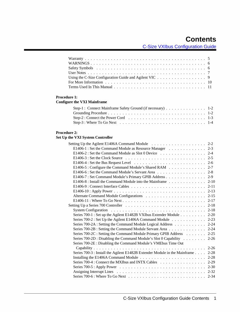
ContentsC-Size VXIbus Configuration Guide
Warranty . . . . . . . . . . . . . . . . . . . . . . . . . . . . . . . . . . . . . . . . . . 5WARNINGS . . . . . . . . . . . . . . . . . . . . . . . . . . . . . . . . . . . . . . . . 6Safety Symbols . . . . . . . . . . . . . . . . . . . . . . . . . . . . . . . . . . . . . . 6User Notes . . . . . . . . . . . . . . . . . . . . . . . . . . . . . . . . . . . . . . . . . 7Using the C-Size Configuration Guide and Agilent VIC . . . . . . . . . . . . . . . . . 9For More Information . . . . . . . . . . . . . . . . . . . . . . . . . . . . . . . . . . . 10Terms Used In This Manual . . . . . . . . . . . . . . . . . . . . . . . . . . . . . . . . 11
Procedure 1:Configure the VXI Mainframe
Step-1 : Connect Mainframe Safety Ground (if necessary) . . . . . . . . . . . . . . 1-2Grounding Procedure . . . . . . . . . . . . . . . . . . . . . . . . . . . . . . . . . . 1-2Step-2 : Connect the Power Cord . . . . . . . . . . . . . . . . . . . . . . . . . . . 1-3Step-3 : Where To Go Next . . . . . . . . . . . . . . . . . . . . . . . . . . . . . . 1-4
Procedure 2:Set Up the VXI System Controller
Setting Up the Agilent E1406A Command Module . . . . . . . . . . . . . . . . . . . 2-2E1406-1 : Set the Command Module as Resource Manager . . . . . . . . . . . . . 2-3E1406-2 : Set the Command Module as Slot 0 Device . . . . . . . . . . . . . . . . 2-4E1406-3 : Set the Clock Source . . . . . . . . . . . . . . . . . . . . . . . . . . . . 2-5E1406-4 : Set the Bus Request Level . . . . . . . . . . . . . . . . . . . . . . . . . 2-6E1406-5 : Configure the Command Module’s Shared RAM . . . . . . . . . . . . . 2-7E1406-6 : Set the Command Module’s Servant Area . . . . . . . . . . . . . . . . . 2-8E1406-7 : Set Command Module’s Primary GPIB Address . . . . . . . . . . . . . . 2-9E1406-8 : Install the Command Module into the Mainframe . . . . . . . . . . . . . 2-10E1406-9 : Connect Interface Cables . . . . . . . . . . . . . . . . . . . . . . . . . . 2-11E1406-10 : Apply Power . . . . . . . . . . . . . . . . . . . . . . . . . . . . . . . . 2-13Alternate Command Module Configurations . . . . . . . . . . . . . . . . . . . . . 2-15E1406-11 : Where To Go Next . . . . . . . . . . . . . . . . . . . . . . . . . . . . . 2-17
Setting Up a Series 700 Controller . . . . . . . . . . . . . . . . . . . . . . . . . . . . 2-18System Configuration . . . . . . . . . . . . . . . . . . . . . . . . . . . . . . . . . 2-18Series 700-1 : Set up the Agilent E1482B VXIbus Extender Module . . . . . . . . . 2-20Series 700-2 : Set Up the Agilent E1406A Command Module . . . . . . . . . . . . 2-23Series 700-2A : Setting the Command Module Logical Address . . . . . . . . . . . 2-24Series 700-2B : Setting the Command Module Servant Area . . . . . . . . . . . . . 2-24Series 700-2C : Setting the Command Module Primary GPIB Address . . . . . . . 2-25Series 700-2D : Disabling the Command Module’s Slot 0 Capability . . . . . . . . 2-26Series 700-2E : Disabling the Command Module’s VMEbus Time Out
Capability . . . . . . . . . . . . . . . . . . . . . . . . . . . . . . . . . . . . . . . 2-26Series 700-3 : Install the Agilent E1482B Extender Module in the Mainframe . . . . 2-28Installing the E1406A Command Module . . . . . . . . . . . . . . . . . . . . . . . 2-28Series 700-4 : Connect the MXIbus and INTX Cables . . . . . . . . . . . . . . . . 2-29Series 700-5 : Apply Power . . . . . . . . . . . . . . . . . . . . . . . . . . . . . . 2-30Assigning Interrupt Lines . . . . . . . . . . . . . . . . . . . . . . . . . . . . . . . 2-32Series 700-6 : Where To Go Next . . . . . . . . . . . . . . . . . . . . . . . . . . . 2-34
C-Size VXIbus Configuration Guide Contents 1
Setting Up an Embedded V743 Controller . . . . . . . . . . . . . . . . . . . . . . . . 2-35V743-1 : The V743 Configuration . . . . . . . . . . . . . . . . . . . . . . . . . . . 2-35The V743 Logical Address and Servant Area . . . . . . . . . . . . . . . . . . . . . 2-37V743-2 : Set Up the Agilent E1406A Command Module . . . . . . . . . . . . . . . 2-37V743-2A : Setting the Command Module Logical Address . . . . . . . . . . . . . . 2-38V743-2B : Setting the Command Module Servant Area . . . . . . . . . . . . . . . . 2-39V743-2C : Setting the Command Module Primary GPIB Address . . . . . . . . . . 2-40V743-2D : Disabling the Command Module’s Slot 0 Capability . . . . . . . . . . . 2-41V743-3 : Install the V743 Controller in the Mainframe . . . . . . . . . . . . . . . . 2-42Installing the E1406A Command Module . . . . . . . . . . . . . . . . . . . . . . . 2-44V743-4 : Apply Power . . . . . . . . . . . . . . . . . . . . . . . . . . . . . . . . . 2-45V743-4A : Enabling Shared Memory . . . . . . . . . . . . . . . . . . . . . . . . . 2-46V743-4B : Assigning Interrupt Lines . . . . . . . . . . . . . . . . . . . . . . . . . 2-47V743-5 : Where To Go Next . . . . . . . . . . . . . . . . . . . . . . . . . . . . . . 2-48
Setting Up an Embedded Agilent RADI-EPC7 486 Computer . . . . . . . . . . . . . . 2-49EPC7-1 : Set the EPC7 as Slot 0 Device . . . . . . . . . . . . . . . . . . . . . . . . 2-50EPC7-1A : Set the EPC7 as Non-Slot 0 Device if Using Multiple Mainframes . . . 2-51EPC7-2 : Install the EPC7 into the Mainframe . . . . . . . . . . . . . . . . . . . . 2-52EPC7-3 : Install EXM Expansion Modules . . . . . . . . . . . . . . . . . . . . . . 2-54EPC7-4 : Configure the Command Module to Work with the EPC7 . . . . . . . . . 2-55EPC7-4A : Set the Command Module’s Logical Address . . . . . . . . . . . . . . . 2-56EPC7-4B : Set the Command Module’s Servant Area . . . . . . . . . . . . . . . . 2-57EPC7-4C : Set the Command Module’s Primary GPIB Address . . . . . . . . . . . 2-58EPC7-4D : Disable the Command Module’s slot 0 and System Controller
Capability . . . . . . . . . . . . . . . . . . . . . . . . . . . . . . . . . . . . . . . 2-59EPC7-5 : Connect Interface Cables . . . . . . . . . . . . . . . . . . . . . . . . . . 2-60EPC7-6 : Apply Power . . . . . . . . . . . . . . . . . . . . . . . . . . . . . . . . . 2-61EPC7-7 : Where To Go Next . . . . . . . . . . . . . . . . . . . . . . . . . . . . . . 2-63
Procedure 3:Set Up the System for Multiple Mainframes
MXIbus-1 : Set Up VXI-MXI Modules for Slot 0 . . . . . . . . . . . . . . . . . . 3-4MXIbus-2 : Set VXI-MXI Modules for Non-Slot 0 . . . . . . . . . . . . . . . . . 3-5MXIbus-3 : Remove the Terminating Networks from Middle VXI-MXI Modules . 3-9MXIbus-4 : Set the VXI-MXI Module’s Logical Address . . . . . . . . . . . . . . 3-10MXIbus-5 : Disable the VMEbus Timeout on Other Modules (VME BTO) . . . . . 3-20MXIbus-6 : Install VXI-MXI Modules into Mainframes . . . . . . . . . . . . . . . 3-22MXIbus-7 : Connect Interface Cables . . . . . . . . . . . . . . . . . . . . . . . . . 3-24MXIbus-8 : Apply Power . . . . . . . . . . . . . . . . . . . . . . . . . . . . . . . 3-25MXIbus-9 : Where To Go Next . . . . . . . . . . . . . . . . . . . . . . . . . . . . 3-25
Procedure 4:Configure and Install Instruments
Step-1 : Download Instrument Drivers . . . . . . . . . . . . . . . . . . . . . . . . . 4-3Step-2 : Set Instrument Logical Addresses . . . . . . . . . . . . . . . . . . . . . . 4-4Step-3 : Install A- and B-Size Modules . . . . . . . . . . . . . . . . . . . . . . . . 4-8Step-4 : Install C-Size Modules . . . . . . . . . . . . . . . . . . . . . . . . . . . . 4-11Step-5 : Install a Chassis Shield . . . . . . . . . . . . . . . . . . . . . . . . . . . . 4-14Step-6 : Install Backplane Connector Shields . . . . . . . . . . . . . . . . . . . . . 4-15Step-7 : Install Faceplate Panels . . . . . . . . . . . . . . . . . . . . . . . . . . . . 4-16Step-8 : Where To Go Next . . . . . . . . . . . . . . . . . . . . . . . . . . . . . . 4-17
2 C-Size VXIbus Configuration Guide Contents
Procedure 5:Apply Power
Agilent E1406 Command Module with an External Computer . . . . . . . . . . . . 5-1HP 9000 Series 700 Computer . . . . . . . . . . . . . . . . . . . . . . . . . . . . . 5-4Agilent E1497A/ E1498A Embedded V743 Controller . . . . . . . . . . . . . . . . 5-7Agilent RADI-EPC7 Embedded 486 Computer . . . . . . . . . . . . . . . . . . . . 5-9Where To Go Next . . . . . . . . . . . . . . . . . . . . . . . . . . . . . . . . . . . 5-13
Procedure 6: System Programming and Debugging
COMM1 : Verify Communication with the Instruments . . . . . . . . . . . . . . . 6-2COMM1A : GPIB Addressing . . . . . . . . . . . . . . . . . . . . . . . . . . . . . 6-2COMM1B : Embedded Controller Addressing . . . . . . . . . . . . . . . . . . . . 6-3COMM1C : SICL Addressing . . . . . . . . . . . . . . . . . . . . . . . . . . . . . 6-4COMM1D : C-SCPI Addressing . . . . . . . . . . . . . . . . . . . . . . . . . . . . 6-5
Debugging Programs . . . . . . . . . . . . . . . . . . . . . . . . . . . . . . . . . . . 6-6DEBUG1 : Sending SCPI Commands . . . . . . . . . . . . . . . . . . . . . . . . . 6-7SCPI Command Structure . . . . . . . . . . . . . . . . . . . . . . . . . . . . . . . 6-7DEBUG2 : Verify the System Logical Addresses . . . . . . . . . . . . . . . . . . . 6-8DEBUG3 : Start Each Program by Fully Resetting Each Instrument . . . . . . . . . 6-9DEBUG4 : Query the Instrument for Errors . . . . . . . . . . . . . . . . . . . . . . 6-9DEBUG5 : Query all Command Parameter Settings . . . . . . . . . . . . . . . . . 6-10DEBUG6 : Verify that the Amount of Data to be Entered is Equal to the Amount of
Data Generated . . . . . . . . . . . . . . . . . . . . . . . . . . . . . . . . . . . . 6-10DEBUG7 : Check the Instrument’s Arm-Trigger Subsystem . . . . . . . . . . . . . 6-11DEBUG8 : Execute Coupled Commands Within a Coupling Group . . . . . . . . . 6-12How to Execute Coupled Commands . . . . . . . . . . . . . . . . . . . . . . . . . 6-12DEBUG9 : Check for Command Synchronization Errors . . . . . . . . . . . . . . . 6-13
Appendix A:Terms and Definitions
What is the Resource Manager? . . . . . . . . . . . . . . . . . . . . . . . . . . . . A-2What are the Slot 0 Functions? . . . . . . . . . . . . . . . . . . . . . . . . . . . . . A-2What is the Command Module’s 10 MHz Clock Source? . . . . . . . . . . . . . . . A-3What is the Command Module’s Bus Request Level? . . . . . . . . . . . . . . . . . A-3What is Command Module Memory . . . . . . . . . . . . . . . . . . . . . . . . . . A-4What is the Servant Area? . . . . . . . . . . . . . . . . . . . . . . . . . . . . . . . A-5What is the Command Module’s Primary GPIB Address? . . . . . . . . . . . . . . A-7What is the VXI-MXI Module? . . . . . . . . . . . . . . . . . . . . . . . . . . . . A-8What are the VXI-MXI Logical Address Windows . . . . . . . . . . . . . . . . . . A-8What is an Instrument Identifier? . . . . . . . . . . . . . . . . . . . . . . . . . . . A-9What are Virtual Instruments? . . . . . . . . . . . . . . . . . . . . . . . . . . . . . A-9What is the Logical Address? . . . . . . . . . . . . . . . . . . . . . . . . . . . . . A-10What are Downloadable Instrument Drivers? . . . . . . . . . . . . . . . . . . . . . A-11What Display Terminals Can Be Used? . . . . . . . . . . . . . . . . . . . . . . . . A-12What are Interrupt Lines? . . . . . . . . . . . . . . . . . . . . . . . . . . . . . . . A-12
Appendix B :Configuration and Start-up Errors
Checking for Instrument Errors . . . . . . . . . . . . . . . . . . . . . . . . . . . . B-7
C-Size VXIbus Configuration Guide Contents 3

Notes
4 C-Size VXIbus Configuration Guide Contents
CertificationAgilent Technologies certifies that this product met its published specifications at the time of shipment from the factory. AgilentTechnologies further certifies that its calibration measurements are traceable to the United States National Institute of Standards andTechnology (formerly National Bureau of Standards), to the extent allowed by that organization’s calibration facility, and to the calibrationfacilities of other International Standards Organization members.
WarrantyThis Agilent Technologies product is warranted against defects in materials and workmanship for a period of one (1) year from date ofshipment. Duration and conditions of warranty for this product may be superseded when the product is integrated into (becomes a partof) other Agilent products. During the warranty period, Agilent Technologies will, at its option, either repair or replace products whichprove to be defective.
For warranty service or repair, this product must be returned to a service facility designated by Agilent Technologies. Buyer shall prepayshipping charges to Agilent and Agilent shall pay shipping charges to return the product to Buyer. However, Buyer shall pay all shippingcharges, duties, and taxes for products returned to Agilent from another country.
Agilent warrants that its software and firmware designated by Agilent for use with a product will execute its programming instructionswhen properly installed on that product. Agilent does not warrant that the operation of the product, or software, or firmware will beuninterrupted or error free.
Limitation Of WarrantyThe foregoing warranty shall not apply to defects resulting from improper or inadequate maintenance by Buyer, Buyer-supplied productsor interfacing, unauthorized modification or misuse, operation outside of the environmental specifications for the product, or improper sitepreparation or maintenance.
The design and implementation of any circuit on this product is the sole responsibility of the Buyer. Agilent does not warrant the Buyer’scircuitry or malfunctions of Agilent products that result from the Buyer’s circuitry. In addition, Agilent does not warrant any damage thatoccurs as a result of the Buyer’s circuit or any defects that result from Buyer-supplied products.
NO OTHER WARRANTY IS EXPRESSED OR IMPLIED. Agilent SPECIFICALLY DISCLAIMS THE IMPLIED WARRANTIESOF MERCHANTABILITY AND FITNESS FOR A PARTICULAR PURPOSE.
Exclusive RemediesTHE REMEDIES PROVIDED HEREIN ARE BUYER’S SOLE AND EXCLUSIVE REMEDIES. Agilent SHALL NOT BE LIABLEFOR ANY DIRECT, INDIRECT, SPECIAL, INCIDENTAL, OR CONSEQUENTIAL DAMAGES, WHETHER BASED ON CON-TRACT, TORT, OR ANY OTHER LEGAL THEORY.
NoticeThe information contained in this document is subject to change without notice. Agilent Technologies MAKES NO WARRANTY OFANY KIND WITH REGARD TO THIS MATERIAL, INCLUDING, BUT NOT LIMITED TO, THE IMPLIED WARRANTIES OFMERCHANTABILITY AND FITNESS FOR A PARTICULAR PURPOSE. Agilent shall not be liable for errors contained herein or forincidental or consequential damages in connection with the furnishing, performance or use of this material. This document containsproprietary information which is protected by copyright. All rights are reserved. No part of this document may be photocopied, reproduced,or translated to another language without the prior written consent of Agilent Technologies, Inc. Agilent assumes no responsibility for theuse or reliability of its software on equipment that is not furnished by Agilent.
U.S. Government Restricted RightsThe Software and Documentation have been developed entirely at private expense. They are delivered and licensed as "commercialcomputer software" as defined in DFARS 252.227- 7013 (Oct 1988), DFARS 252.211-7015 (May 1991) or DFARS 252.227-7014 (Jun1995), as a "commercial item" as defined in FAR 2.101(a), or as "Restricted computer software" as defined in FAR 52.227-19 (Jun 1987)(orany equivalent agency regulation or contract clause), whichever is applicable. You have only those rights provided for such Software andDocumentation by the applicable FAR or DFARS clause or the Agilent standard software agreement for the product involved.
Agilent C-Size VXIbus Configuration GuideEdition 1 Rev 2
Copyright © 1998-2006 Agilent Technologies, Inc. All Rights Reserved.
Agilent C-Size VXIbus Configuration Guide 5
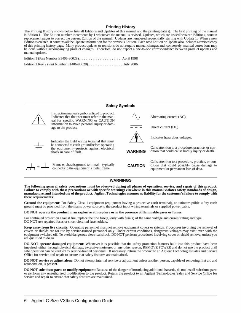
Frame or chassis ground terminal—typicallyconnects to the equipment’s metal frame.
Alternating current (AC).
Direct current (DC).
Indicates hazardous voltages.
Calls attention to a procedure, practice, or con-dition that could cause bodily injury or death.
Calls attention to a procedure, practice, or con-dition that could possibly cause damage toequipment or permanent loss of data.
Indicates the field wiring terminal that mustbe connected to earth ground before operatingthe equipment—protects against electricalshock in case of fault.
Instruction manual symbol affixed to product.Indicates that the user must refer to the man-ual for specific WARNING or CAUTIONinformation to avoid personal injury or dam-age to the product.
or
WARNINGSThe following general safety precautions must be observed during all phases of operation, service, and repair of this product.Failure to comply with these precautions or with specific warnings elsewhere in this manual violates safety standards of design,manufacture, and intended use of the product. Agilent Technologies assumes no liability for the customer’s failure to comply withthese requirements.
Ground the equipment: For Safety Class 1 equipment (equipment having a protective earth terminal), an uninterruptible safety earthground must be provided from the mains power source to the product input wiring terminals or supplied power cable.
DO NOT operate the product in an explosive atmosphere or in the presence of flammable gases or fumes.
For continued protection against fire, replace the line fuse(s) only with fuse(s) of the same voltage and current rating and type. DO NOT use repaired fuses or short-circuited fuse holders.
Keep away from live circuits: Operating personnel must not remove equipment covers or shields. Procedures involving the removal ofcovers or shields are for use by service-trained personnel only. Under certain conditions, dangerous voltages may exist even with theequipment switched off. To avoid dangerous electrical shock, DO NOT perform procedures involving cover or shield removal unless youare qualified to do so.
DO NOT operate damaged equipment: Whenever it is possible that the safety protection features built into this product have beenimpaired, either through physical damage, excessive moisture, or any other reason, REMOVE POWER and do not use the product untilsafe operation can be verified by service-trained personnel. If necessary, return the product to an Agilent Technologies Sales and ServiceOffice for service and repair to ensure that safety features are maintained.
DO NOT service or adjust alone: Do not attempt internal service or adjustment unless another person, capable of rendering first aid andresuscitation, is present.
DO NOT substitute parts or modify equipment: Because of the danger of introducing additional hazards, do not install substitute partsor perform any unauthorized modification to the product. Return the product to an Agilent Technologies Sales and Service Office forservice and repair to ensure that safety features are maintained.
Printing HistoryThe Printing History shown below lists all Editions and Updates of this manual and the printing date(s). The first printing of the manualis Edition 1. The Edition number increments by 1 whenever the manual is revised. Updates, which are issued between Editions, containreplacement pages to correct the current Edition of the manual. Updates are numbered sequentially starting with Update 1. When a newEdition is created, it contains all the Update information for the previous Edition. Each new Edition or Update also includes a revised copyof this printing history page. Many product updates or revisions do not require manual changes and, conversely, manual corrections maybe done without accompanying product changes. Therefore, do not expect a one-to-one correspondence between product updates andmanual updates.
Edition 1 (Part Number E1406-90028). . . . . . . . . . . . . . . . . . . . . . . . April 1998
Edition 1 Rev 2 (Part Number E1406-90028) . . . . . . . . . . . . . . . . . . . July 2006
Safety Symbols
WARNING
CAUTION
6 Agilent C-Size VXIbus Configuration Guide

Notes
Agilent C-Size VXIbus Configuration Guide 7

Notes
8 Agilent C-Size VXIbus Configuration Guide
Using the C-Size Configuration Guide and Agilent VIC
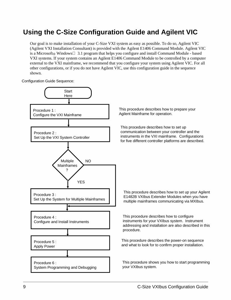
Our goal is to make installation of your C-Size VXI system as easy as possible. To do so, Agilent VIC (Agilent VXI Installation Consultant) is provided with the Agilent E1406 Command Module. Agilent VICis a Microsoft® Windows 3.1 program that helps you configure and install Command Module - basedVXI systems. If your system contains an Agilent E1406 Command Module to be controlled by a computerexternal to the VXI mainframe, we recommend that you configure your system using Agilent VIC. For allother configurations, or if you do not have Agilent VIC, use this configuration guide in the sequenceshown.
Procedure 1 :Configure the VXI Mainframe
StartHere
Procedure 2 :Set Up the VXI System Controller
MultipleMainframes ?
Procedure 3 :Set Up the System for Multiple Mainframes
Procedure 4 :Configure and Install Instruments
Procedure 5 :Apply Power
This procedure describes how to prepare yourAgilent Mainframe for operation.
This procedure describes how to set upcommunication between your controller and theinstruments in the VXI mainframe. Configurationsfor five different controller platforms are described.
This procedure describes how to set up your AgilentE1482B VXIbus Extender Modules when you havemultiple mainframes communicating via MXIbus.
This procedure describes how to configureinstruments for your VXIbus system. Instrumentaddressing and installation are also described in thisprocedure.
This procedure describes the power-on sequenceand what to look for to confirm proper installation.
YES
NO
Procedure 6 :System Programming and Debugging
This procedure shows you how to start programmingyour VXIbus system.
Configuration Guide Sequence:
9 C-Size VXIbus Configuration Guide
For More Information
This manual describes how to get a C-Size VXIbus System up and runningquickly. You may require information from other manuals. The followinglist describes other manuals you may need to refer to.
• To find additional information on the Agilent E1406/05 CommandModule:
Agilent E1406A Command Module User’s Manual (E1406-9000x)
• To find operating and programming information on Agilent plug-inmodules:
Refer to the manual that came with the module (E14xx-9000x or(E13xx-9000x)
• To find information on the Standard Commands for ProgrammableInstruments language (SCPI):
Beginner’s Guide to SCPI Available from Addison-WesleyPublishing at 1-800-822-6339
• To find information on installing the Agilent E1489I MXIbusController Interface Card in an HP 9000 Series 700 Computer:
Agilent E1489I MXIbus Controller Interface For HP 9000 Series700 workstations installation Guide and Overview
• To find information on Agilent Compiled SCPI
Agilent E1570A/B E1572A Compiled SCPI for HP-UX Agilent E1571A Compiled SCPI for MS-DOS
• To find information on the VISA Language
Agilent VISA User’s Guide
C-Size VXIbus Configuration Guide 10
Terms Used In This Manual
The following is a list of terms used in this manual. For more informationon these terms, see Appendix A, "Terms and Definitions."
Bus Request Level The bus request level is a priority at which theCommand Module can request the use of the data transfer bus.
Cardcage A cardcage is a VXIbus mainframe which allowsinstruments on a card to be plugged in and operate in a VXIenvironment. The Agilent E1401A Mainframe is an example of anAgilent cardcage.
CLK10 This is the 10 MHz system clock. Clk10 is usuallyprovided by the system controller.
Command Module Primary GPIB Address The primary GPIBaddress identifies the GPIB port.
C-SCPI Compiled SCPI is a set of C programming tools that allowyou to program register-based instruments using the high-levelSCPI language.
Data Transfer Bus The data transfer bus (DTB) is used foraddressing and data transfer.
Downloadable Device Drivers Device drivers enableregister-based modules to be programmed from the Agilent E1406Command Module with SCPI Commands. Some drivers areinstalled at the factory and other have to be installed by the user.
GPIB GPIB is Agilent Technologies’ implementation ofANSI/IEEE Standard 488.1-1978 "IEEE Standard Digital Interfacefor Programmable Instrumentation."
Instrument In this manual an instrument refers to an instrument ona card that can be plugged into a VXI cardcage.
Logical Address The logical address is used to identify aninstrument in a VXIbus system.
Mainframe A mainframe is a VXIbus cardcage which allowsinstruments on a card to be plugged in and operate in a VXIenvironment. The Agilent E1401A is an example of an Agilentmainframe.
Module A module is an instrument on a card.
11 C-Size VXIbus Configuration Guide
Resource Manager The resource manager runs at power on andidentifies all plug-in modules installed in the mainframe. Theresource manager also controls commander / servant hierarchies,allocates interrupt lines, performs address mapping, and starts thesystem operation.
SCPI SCPI stands for Standard Commands for ProgrammableInstruments. It is an industry standard instrument control languagethat is supported by a consortium of manufacturers.
Servant Area The servant area of a commander defines a range oflogical addresses in which all instruments within the address rangespecified report to that commander.
Secondary GPIB Address The secondary GPIB address iscombined with the computer’s interface select code and CommandModules primary GPIB address to form a module’s complete GPIBaddress.
Slot 0 Device The slot 0 device locates where modules are installedin the mainframe and manages data flow across the VXIbusbackplane. The system clock is also provided by the slot 0 device.
Virtual Instruments A virtual instrument is a combination ofseveral modules that are treated as a single instrument and accessedat a single address.
VXI VXIbus is an open architecture instrument interface forcardcage instrumentation.
VXI-MXI Module A VXI-MXI Module allows you to configuremultiple mainframes to function as a single VXIbus System.
C-Size VXIbus Configuration Guide 12
Procedure 1:Configure the VXI Mainframe
This procedure describes how to configure the Agilent E1401B and AgilentE1421B VXI mainframes in preparation for installing modules and applyingpower. This procedure consists of the following steps:
• Connect mainframe safety ground (if necessary)
• Connect the power cord
Once you have completed the applicable steps in this procedure, continuewith the next procedure, "Procedure 2 : Set Up the VXI SystemController."
WARNING SHOCK HAZARD. Only service-trained personnel who areaware of the hazards involved should install, remove, orconfigure the system. Before you perform any procedures,disconnect AC power and field wiring from the mainframe.
CAUTION STATIC ELECTRICITY. Static electricity is a major cause ofcomponent failure. To prevent damage to the electricalcomponents in the mainframe and plug-in modules, useanti-static techniques whenever handling a module.
1-1 Configure the VXI Mainframe C-Size Configuration Guide
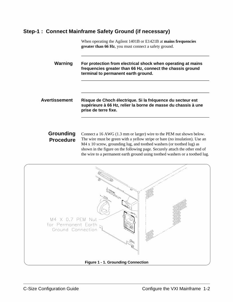
Step-1 : Connect Mainframe Safety Ground (if necessary)
When operating the Agilent 1401B or E1421B at mains frequenciesgreater than 66 Hz, you must connect a safety ground.
Warning For protection from electrical shock when operating at mainsfrequencies greater than 66 Hz, connect the chassis groundterminal to permanent earth ground.
Avertissement Risque de Choch électrique. Si la fréquence du secteur estsupérieure à 66 Hz, relier la borne de masse du chassis à uneprise de terre fixe.
GroundingProcedure
Connect a 16 AWG (1.3 mm or larger) wire to the PEM nut shown below.The wire must be green with a yellow stripe or bare (no insulation). Use anM4 x 10 screw, grounding lug, and toothed washers (or toothed lug) asshown in the figure on the following page. Securely attach the other end ofthe wire to a permanent earth ground using toothed washers or a toothed lug.
Figure 1 - 1. Grounding Connection
C-Size Configuration Guide Configure the VXI Mainframe 1-2
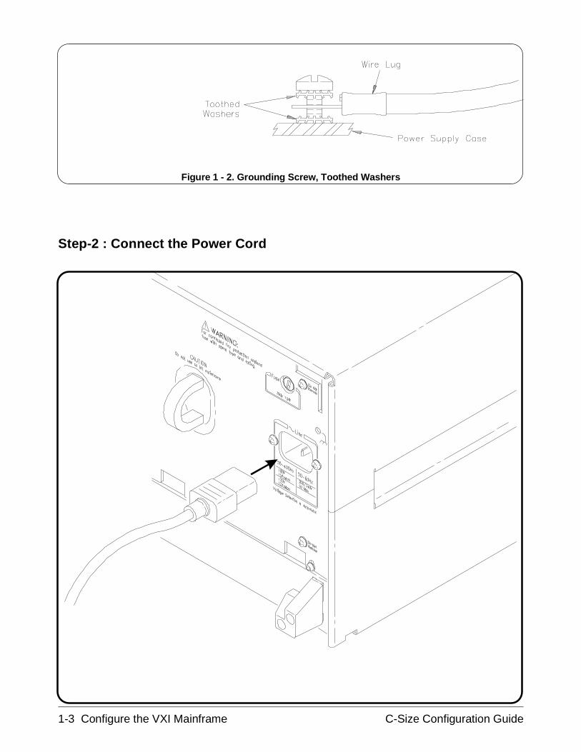
Step-2 : Connect the Power Cord
Figure 1 - 2. Grounding Screw, Toothed Washers
1-3 Configure the VXI Mainframe C-Size Configuration Guide
Step-3 : Where To Go Next
If you have additional mainframes repeat this procedure until allmainframes are configured. Once configured, continue with the followingprocedure:
• "Procedure 2 : Set Up the VXI System Controller"
C-Size Configuration Guide Configure the VXI Mainframe 1-4
Procedure 2:Set Up the VXI System Controller
The controller to VXI mainframe interface determines how commands anddata will flow between the controller and the mainframe. This procedure isdivided into five sections according to the controller used:
• Setting Up the Agilent E1406A Command Module - This sectioncovers the setup of the Agilent E1406A Command Moduleconnected to an external controller using the General PurposeInterface Bus (GPIB). See Page 2-2
• Setting Up a Series 700 Controller - This section covers the setupof an HP 9000 Series 700 external controller with an Agilent E1489IMXIbus Controller Interface Card connected to an Agilent E1482VXI-MXI Bus Extender Module in slot 0. See Page 2-18
• Setting Up an Embedded V743 Controller - This section coversthe setup of an Agilent E1497A/98A Embedded V743 controllerwith the VXIbus as the communication path. See Page 2-35
• Setting Up an Embedded Agilent RADI-EPC7 486 Computer -This section covers the setup of an Agilent RADI-EPC7 EmbeddedComputer with the VXIbus as the communication path. See Page 2-49
WARNING SHOCK HAZARD. Only service-trained personnel who are awareof the hazards involved should install, remove, or configure thesystem. Before you perform any procedures in this guide,disconnect AC power and field wiring from the mainframe.
CAUTION STATIC ELECTRICITY. Static electricity is a major cause ofcomponent failure. To prevent damage to the electricalcomponents in the mainframe and plug-in modules, observeanti-static techniques whenever handling a module.
2-1 Set Up the VXI System Controller C-Size Configuration Guide
Setting Up the Agilent E1406A Command Module
This procedure explains how to set up and install an Agilent 75000 Series CVXIbus system with an external computer (Personal Computer orWorkstation) connected to the Agilent E1406A Command Module viaGPIB. This procedure consists of the following steps:
• E1406-1 : Set the Command Module as Resource Manager
• E1406-2 : Set the Command Module as Slot 0 Device
• E1406-3 : Set the Clock Source
• E1406-4 : Set the Bus Request Level
• E1406-5 : Configure the Command Module’s Shared RAM
• E1406-6 : Set the Command Module’s Servant Area
• E1406-7 : Set the Command Module’s Primary GPIB Address
• E1406-8 : Install the Command Module into the Mainframe
• E1406-9 : Connect Interface Cables
• E1406-10 : Apply Power
• E1406-11 : Where To Go Next
If you need information on terms used in this manual, see Appendix A,"Terms and Definitions."
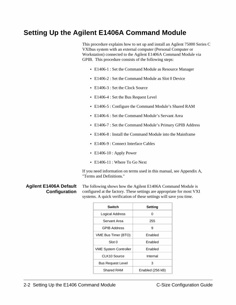
Agilent E1406A DefaultConfiguration
The following shows how the Agilent E1406A Command Module isconfigured at the factory. These settings are appropriate for most VXIsystems. A quick verification of these settings will save you time.
Switch Setting
Logical Address 0
Servant Area 255
GPIB Address 9
VME Bus Timer (BTO) Enabled
Slot 0 Enabled
VME System Controller Enabled
CLK10 Source Internal
Bus Request Level 3
Shared RAM Enabled (256 kB)
2-2 Setting Up the E1406 Command Module C-Size Configuration Guide
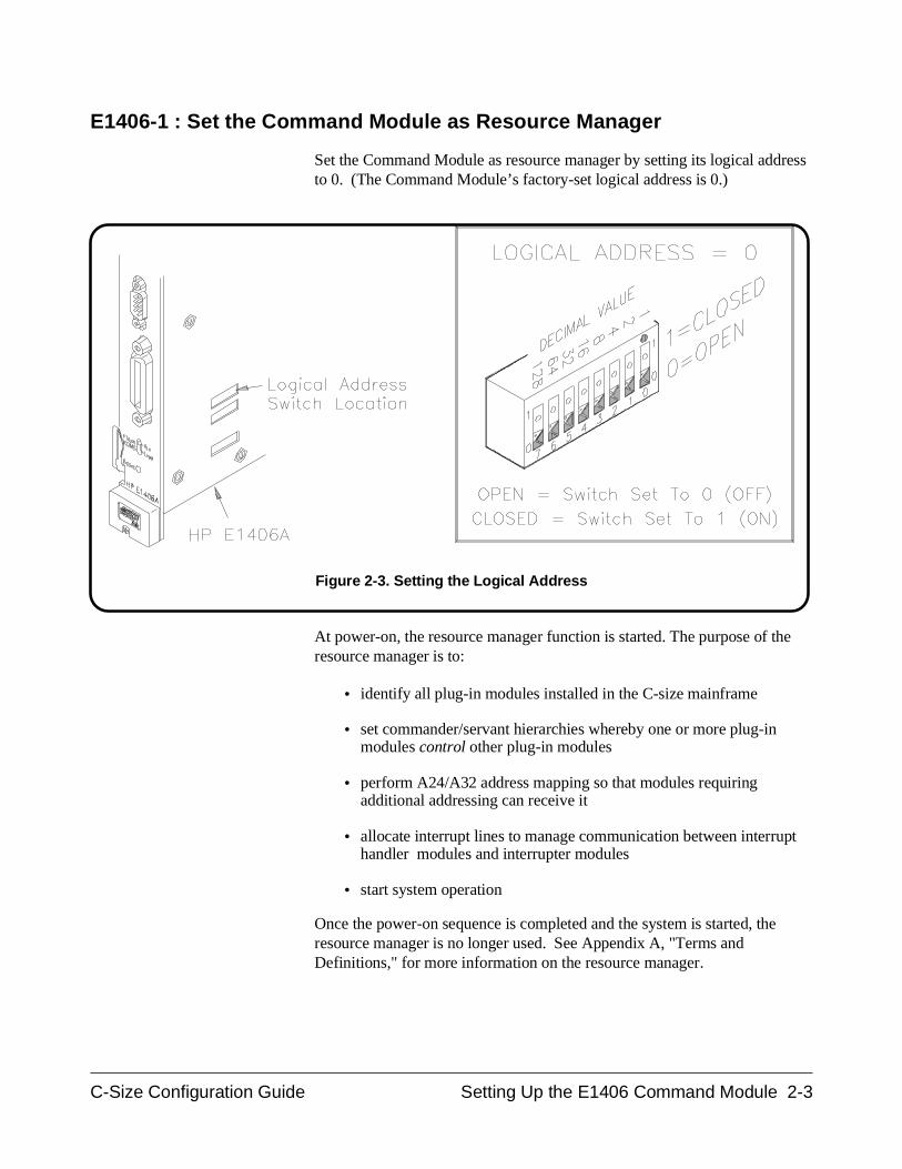
E1406-1 : Set the Command Module as Resource Manager
Set the Command Module as resource manager by setting its logical addressto 0. (The Command Module’s factory-set logical address is 0.)
At power-on, the resource manager function is started. The purpose of theresource manager is to:
• identify all plug-in modules installed in the C-size mainframe
• set commander/servant hierarchies whereby one or more plug-inmodules control other plug-in modules
• perform A24/A32 address mapping so that modules requiringadditional addressing can receive it
• allocate interrupt lines to manage communication between interrupthandler modules and interrupter modules
• start system operation
Once the power-on sequence is completed and the system is started, theresource manager is no longer used. See Appendix A, "Terms andDefinitions," for more information on the resource manager.
Figure 2-3. Setting the Logical Address
C-Size Configuration Guide Setting Up the E1406 Command Module 2-3
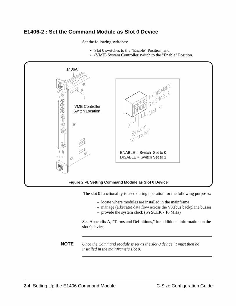
E1406-2 : Set the Command Module as Slot 0 Device
Set the following switches:
• Slot 0 switches to the "Enable" Position, and • (VME) System Controller switch to the "Enable" Position.
The slot 0 functionality is used during operation for the following purposes:
– locate where modules are installed in the mainframe– manage (arbitrate) data flow across the VXIbus backplane busses– provide the system clock (SYSCLK - 16 MHz)
See Appendix A, "Terms and Definitions," for additional information on theslot 0 device.
NOTE Once the Command Module is set as the slot 0 device, it must then beinstalled in the mainframe’s slot 0.
E1406A
VME ControllerSwitch Location
ENABLE = Switch Set to 0DISABLE = Switch Set to 1
Figure 2 -4. Setting Command Module as Slot 0 Device
2-4 Setting Up the E1406 Command Module C-Size Configuration Guide
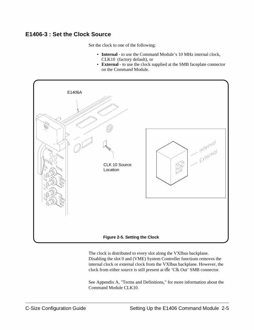
E1406-3 : Set the Clock Source
Set the clock to one of the following:
• Internal - to use the Command Module’s 10 MHz internal clock,CLK10 (factory default), or
• External - to use the clock supplied at the SMB faceplate connectoron the Command Module.
The clock is distributed to every slot along the VXIbus backplane.Disabling the slot 0 and (VME) System Controller functions removes theinternal clock or external clock from the VXIbus backplane. However, theclock from either source is still present at the ’Clk Out’ SMB connector.
See Appendix A, "Terms and Definitions," for more information about theCommand Module CLK10.
E1406A
CLK 10 SourceLocation
Figure 2-5. Setting the Clock
C-Size Configuration Guide Setting Up the E1406 Command Module 2-5
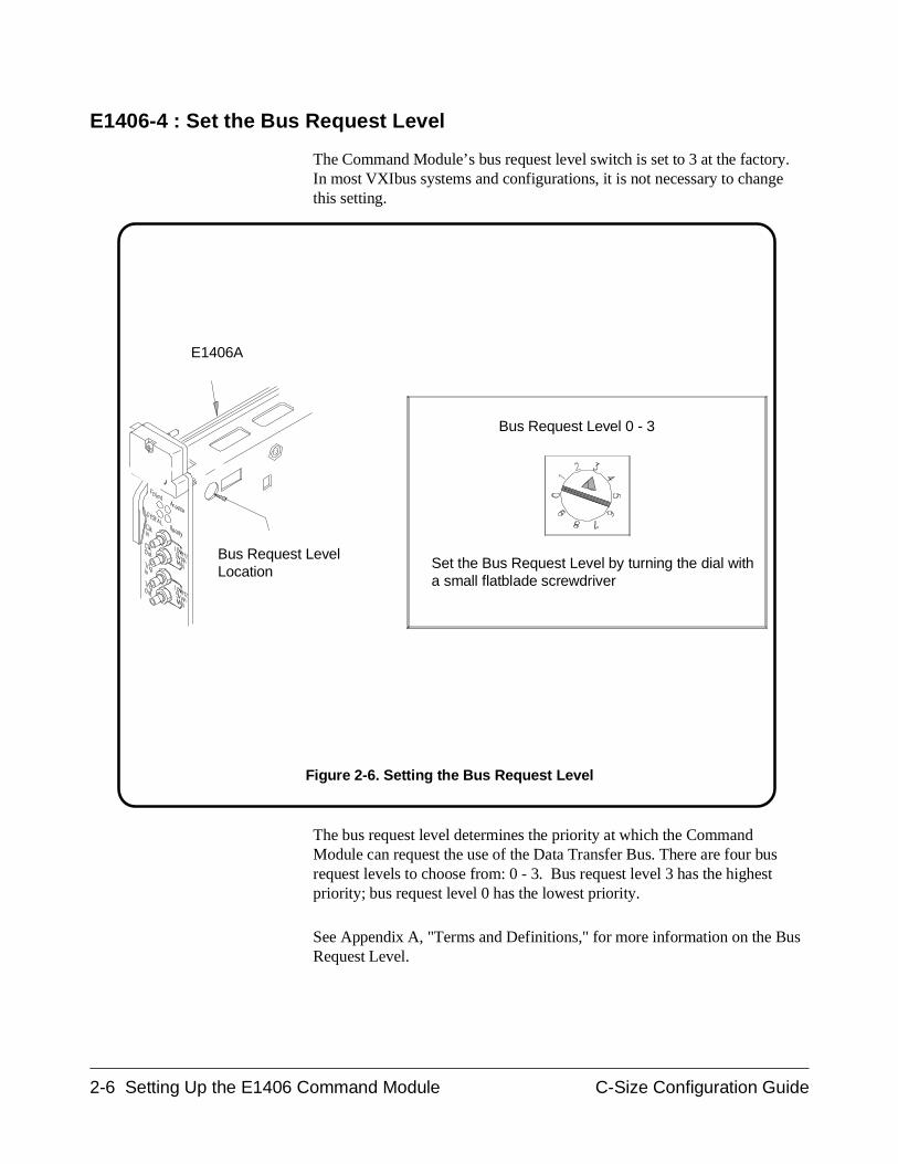
E1406-4 : Set the Bus Request Level
The Command Module’s bus request level switch is set to 3 at the factory.In most VXIbus systems and configurations, it is not necessary to changethis setting.
The bus request level determines the priority at which the CommandModule can request the use of the Data Transfer Bus. There are four busrequest levels to choose from: 0 - 3. Bus request level 3 has the highestpriority; bus request level 0 has the lowest priority.
See Appendix A, "Terms and Definitions," for more information on the BusRequest Level.
E1406A
Bus Request LevelLocation Set the Bus Request Level by turning the dial with
a small flatblade screwdriver
Bus Request Level 0 - 3
Figure 2-6. Setting the Bus Request Level
2-6 Setting Up the E1406 Command Module C-Size Configuration Guide
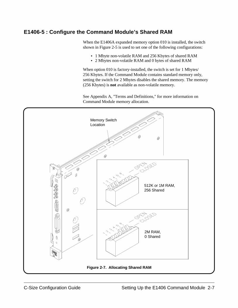
E1406-5 : Configure the Command Module’s Shared RAM
When the E1406A expanded memory option 010 is installed, the switchshown in Figure 2-5 is used to set one of the following configurations:
• 1 Mbyte non-volatile RAM and 256 Kbytes of shared RAM• 2 Mbytes non-volatile RAM and 0 bytes of shared RAM
When option 010 is factory-installed, the switch is set for 1 Mbytes/256 Kbytes. If the Command Module contains standard memory only,setting the switch for 2 Mbytes disables the shared memory. The memory(256 Kbytes) is not available as non-volatile memory.
See Appendix A, "Terms and Definitions," for more information onCommand Module memory allocation.
Memory SwitchLocation
512K or 1M RAM, 256 Shared
2M RAM, 0 Shared
Figure 2-7. Allocating Shared RAM
C-Size Configuration Guide Setting Up the E1406 Command Module 2-7
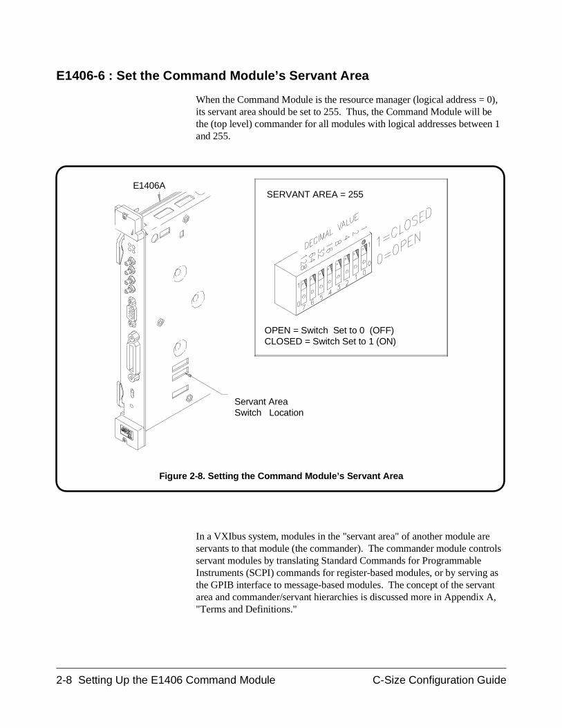
E1406-6 : Set the Command Module’s Servant Area
When the Command Module is the resource manager (logical address = 0),its servant area should be set to 255. Thus, the Command Module will bethe (top level) commander for all modules with logical addresses between 1and 255.
In a VXIbus system, modules in the "servant area" of another module areservants to that module (the commander). The commander module controlsservant modules by translating Standard Commands for ProgrammableInstruments (SCPI) commands for register-based modules, or by serving asthe GPIB interface to message-based modules. The concept of the servantarea and commander/servant hierarchies is discussed more in Appendix A,"Terms and Definitions."
SERVANT AREA = 255
Servant AreaSwitch Location
OPEN = Switch Set to 0 (OFF) CLOSED = Switch Set to 1 (ON)
E1406A
Figure 2-8. Setting the Command Module’s Servant Area
2-8 Setting Up the E1406 Command Module C-Size Configuration Guide
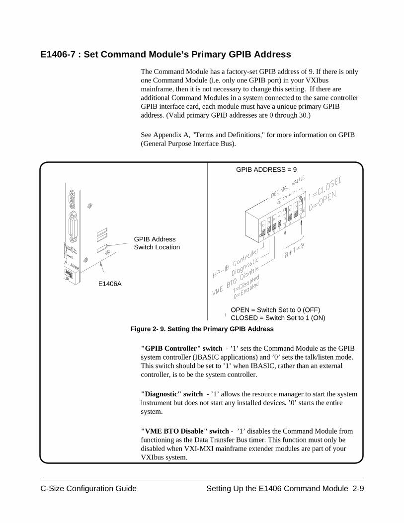
E1406-7 : Set Command Module’s Primary GPIB Address
The Command Module has a factory-set GPIB address of 9. If there is onlyone Command Module (i.e. only one GPIB port) in your VXIbusmainframe, then it is not necessary to change this setting. If there areadditional Command Modules in a system connected to the same controllerGPIB interface card, each module must have a unique primary GPIBaddress. (Valid primary GPIB addresses are 0 through 30.)
See Appendix A, "Terms and Definitions," for more information on GPIB(General Purpose Interface Bus).
"GPIB Controller" switch - ’1’ sets the Command Module as the GPIBsystem controller (IBASIC applications) and ’0’ sets the talk/listen mode.This switch should be set to ’1’ when IBASIC, rather than an externalcontroller, is to be the system controller.
"Diagnostic" switch - ’1’ allows the resource manager to start the systeminstrument but does not start any installed devices. ’0’ starts the entiresystem.
"VME BTO Disable" switch - ’1’ disables the Command Module fromfunctioning as the Data Transfer Bus timer. This function must only bedisabled when VXI-MXI mainframe extender modules are part of yourVXIbus system.
E1406A
GPIB AddressSwitch Location
OPEN = Switch Set to 0 (OFF)CLOSED = Switch Set to 1 (ON)
GPIB ADDRESS = 9
Figure 2- 9. Setting the Primary GPIB Address
C-Size Configuration Guide Setting Up the E1406 Command Module 2-9
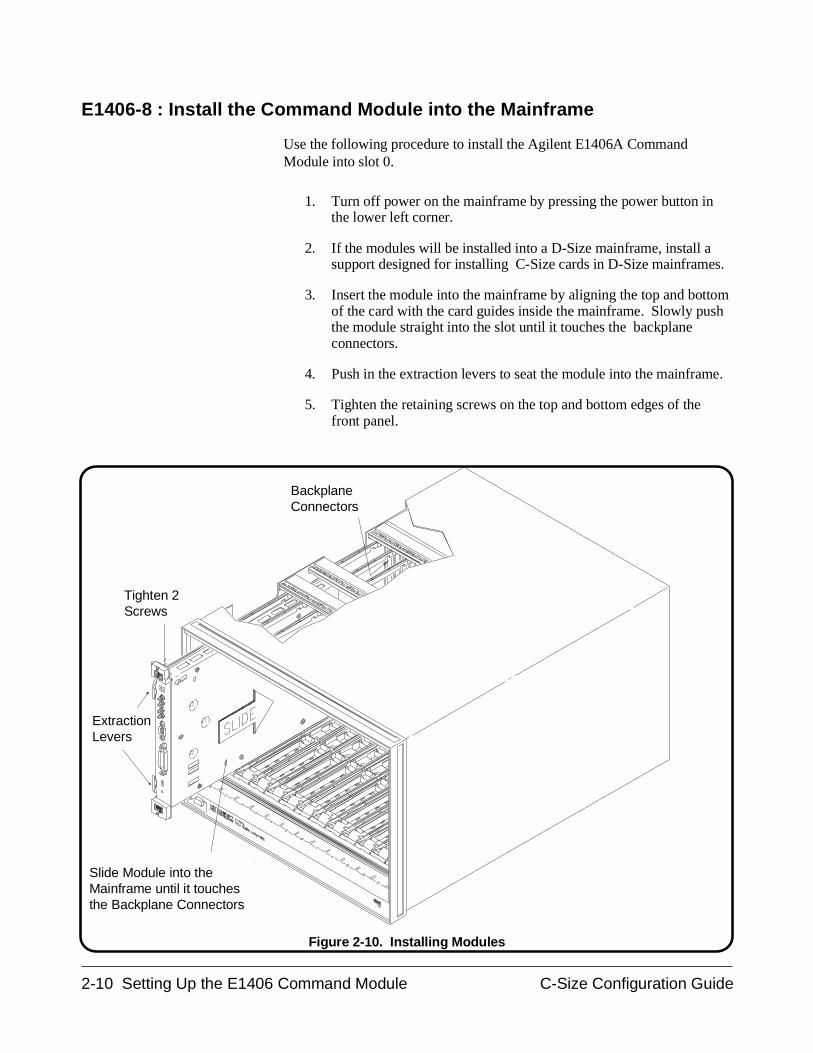
E1406-8 : Install the Command Module into the Mainframe
Use the following procedure to install the Agilent E1406A CommandModule into slot 0.
1. Turn off power on the mainframe by pressing the power button inthe lower left corner.
2. If the modules will be installed into a D-Size mainframe, install asupport designed for installing C-Size cards in D-Size mainframes.
3. Insert the module into the mainframe by aligning the top and bottomof the card with the card guides inside the mainframe. Slowly pushthe module straight into the slot until it touches the backplaneconnectors.
4. Push in the extraction levers to seat the module into the mainframe.
5. Tighten the retaining screws on the top and bottom edges of thefront panel.
BackplaneConnectors
Tighten 2Screws
Slide Module into theMainframe until it touchesthe Backplane Connectors
Extraction Levers
Figure 2-10. Installing Modules
2-10 Setting Up the E1406 Command Module C-Size Configuration Guide
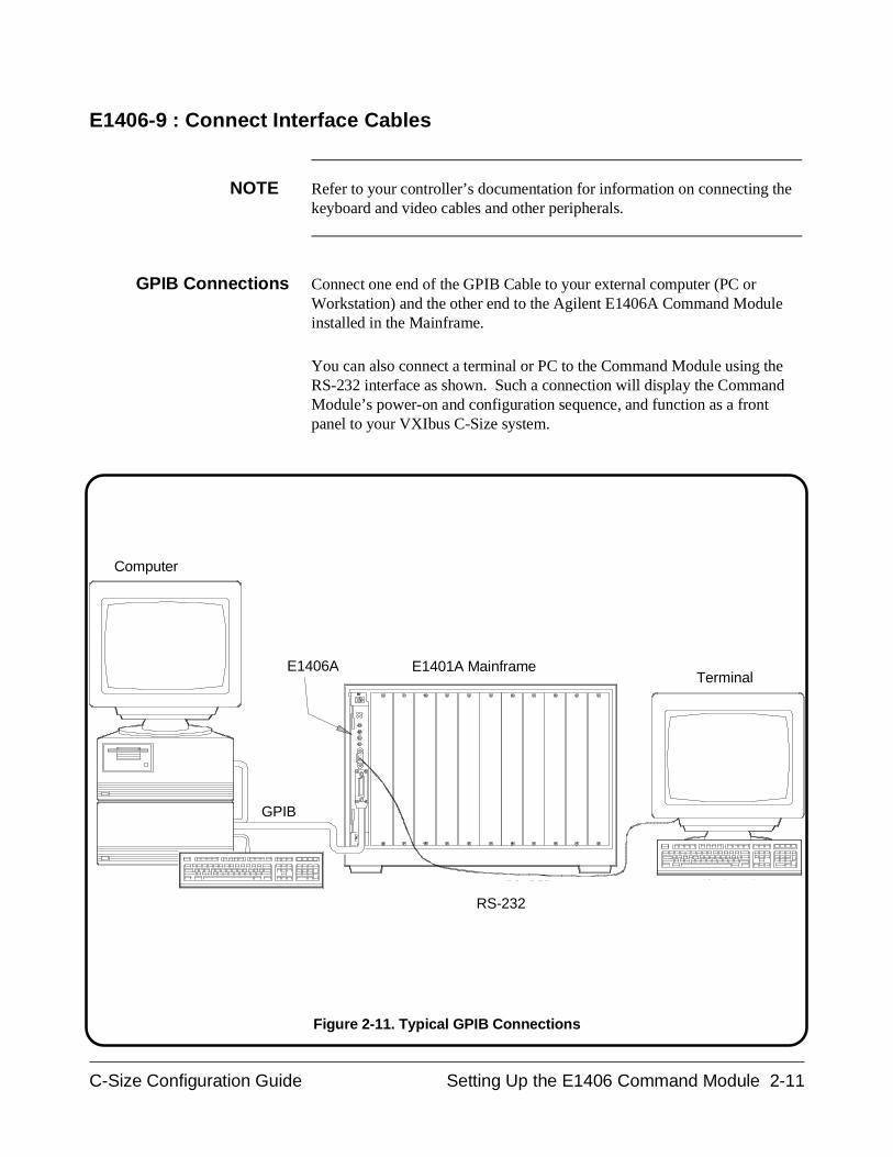
E1406-9 : Connect Interface Cables
NOTE Refer to your controller’s documentation for information on connecting thekeyboard and video cables and other peripherals.
GPIB Connections Connect one end of the GPIB Cable to your external computer (PC orWorkstation) and the other end to the Agilent E1406A Command Moduleinstalled in the Mainframe.
You can also connect a terminal or PC to the Command Module using theRS-232 interface as shown. Such a connection will display the CommandModule’s power-on and configuration sequence, and function as a frontpanel to your VXIbus C-Size system.
E1406ATerminal
RS-232
Computer
E1401A Mainframe
GPIB
Figure 2-11. Typical GPIB Connections
C-Size Configuration Guide Setting Up the E1406 Command Module 2-11
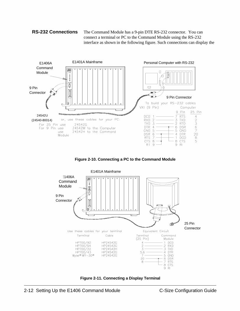
RS-232 Connections The Command Module has a 9-pin DTE RS-232 connector. You canconnect a terminal or PC to the Command Module using the RS-232interface as shown in the following figure. Such connections can display the
25 Pin Connector
9 Pin Connector
E1401A Mainframe
E1406ACommandModule
Figure 2-11. Connecting a Display Terminal
E1406ACommandModule
E1401A Mainframe
9 Pin Connector
HP 24542U
(24540-80014)
Personal Computer with RS-232
9 PinConnector
Figure 2-10. Connecting a PC to the Command Module
2-12 Setting Up the E1406 Command Module C-Size Configuration Guide
Command Module’s power-on and configuration sequence, and function asa front panel to your VXIbus C-Size system.
See Appendix A, "Terms and Definitions," for information on theCommand Module’s RS-232 interface configuration
E1406-10 : Apply Power
Check that the Agilent E1406A Flash ROMS switch is in the "Run"position and then turn on the VXI mainframe. An example of the E1406A’spower-on and configuration sequence is shown in Figure 2-12. Thissequence can be monitored on an RS-232 terminal or printer connected tothe Command Module’s RS-232 serial interface port (see "RS-232Connections" on page 2- 12). Pressing CTRL S on the terminal keyboardpauses the sequence. Pressing CTRL Q allows the sequence to resume. Notethat once the sequence is paused, it remains paused until CTRL Q ispressed.
NOTE If a serial terminal or printer is not available, the program in Procedure 6can be used to check your system.
Configuration andStart-Up Errors
If the Command Module fails its self test, the "Failed" annunciator lights upon the faceplate. Should this occur:
• turn the mainframe off, remove the Command Module, check theconfiguration switches (i.e. logical address, slot 0/system controllerenable).
• if necessary, call your nearest Agilent Technologies sales and serviceoffice.
NOTE When using the Command Module for the first time or when the mainframehas not been turned on for at least one week, leave the mainframe on for atleast 15 hours to fully charge the Command Module’s battery.
If a configuration or start-up error such as an invalid address or failed selftest occurs, the error is reported in the power-on and configurationsequence. A list of the configuration and start-up error messages and theircauses can be found at the end of this guide.
C-Size Configuration Guide Setting Up the E1406 Command Module 2-13
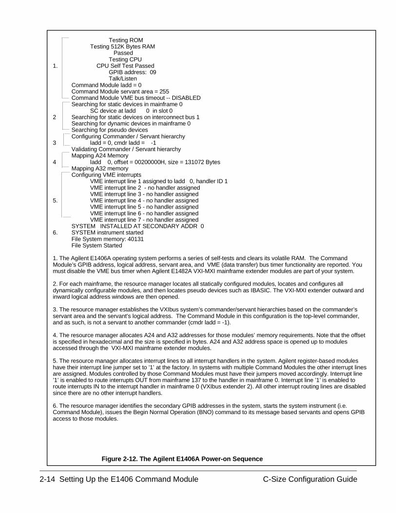
Testing ROMTesting 512K Bytes RAM
PassedTesting CPU
1. CPU Self Test PassedGPIB address: 09Talk/Listen
Command Module ladd = 0Command Module servant area = 255Command Module VME bus timeout -- DISABLEDSearching for static devices in mainframe 0
SC device at ladd 0 in slot 02 Searching for static devices on interconnect bus 1
Searching for dynamic devices in mainframe 0Searching for pseudo devicesConfiguring Commander / Servant hierarchy
3 ladd = 0, cmdr ladd = -1Validating Commander / Servant hierarchyMapping A24 Memory
4 ladd 0, offset = 00200000H, size = 131072 BytesMapping A32 memoryConfiguring VME interrupts
VME interrupt line 1 assigned to ladd 0, handler ID 1VME interrupt line 2 - no handler assignedVME interrupt line 3 - no handler assigned
5. VME interrupt line 4 - no handler assignedVME interrupt line 5 - no handler assignedVME interrupt line 6 - no handler assignedVME interrupt line 7 - no handler assigned
SYSTEM INSTALLED AT SECONDARY ADDR 06. SYSTEM instrument started
File System memory: 40131File System Started
1. The Agilent E1406A operating system performs a series of self-tests and clears its volatile RAM. The CommandModule’s GPIB address, logical address, servant area, and VME (data transfer) bus timer functionality are reported. Youmust disable the VME bus timer when Agilent E1482A VXI-MXI mainframe extender modules are part of your system.
2. For each mainframe, the resource manager locates all statically configured modules, locates and configures alldynamically configurable modules, and then locates pseudo devices such as IBASIC. The VXI-MXI extender outward andinward logical address windows are then opened.
3. The resource manager establishes the VXIbus system’s commander/servant hierarchies based on the commander’sservant area and the servant’s logical address. The Command Module in this configuration is the top-level commander,and as such, is not a servant to another commander (cmdr ladd = -1).
4. The resource manager allocates A24 and A32 addresses for those modules’ memory requirements. Note that the offsetis specified in hexadecimal and the size is specified in bytes. A24 and A32 address space is opened up to modulesaccessed through the VXI-MXI mainframe extender modules.
5. The resource manager allocates interrupt lines to all interrupt handlers in the system. Agilent register-based moduleshave their interrupt line jumper set to ’1’ at the factory. In systems with multiple Command Modules the other interrupt linesare assigned. Modules controlled by those Command Modules must have their jumpers moved accordingly. Interrupt line’1’ is enabled to route interrupts OUT from mainframe 137 to the handler in mainframe 0. Interrupt line ’1’ is enabled toroute interrupts IN to the interrupt handler in mainframe 0 (VXIbus extender 2). All other interrupt routing lines are disabledsince there are no other interrupt handlers.
6. The resource manager identifies the secondary GPIB addresses in the system, starts the system instrument (i.e.Command Module), issues the Begin Normal Operation (BNO) command to its message based servants and opens GPIBaccess to those modules.
Figure 2-12. The Agilent E1406A Power-on Sequence
2-14 Setting Up the E1406 Command Module C-Size Configuration Guide
AlternateCommand Module
Configurations
The procedures in this chapter have described how to configure theAgilent E1406A Command Module as the system’s resource manager andslot 0 device. There may be times when you do not need a CommandModule configured for these functions. The following sections describesuch situations.
Resource ManagerOnly
If the Command Module is to function only as the resource manager and notas the slot 0 device (note that dynamic configuration and slot identificationwill not be done):
1. Set the Command Module’s logical address to 0.
2. Set the Slot 0 and System Controller switches to "Disable".
3. Install the Command Module in a slot other than slot 0.
4. Configure another device to provide the system’s slot 0 functions.
Slot 0 Only If the Command Module is to function only as the slot 0 device and not asthe resource manager:
1. Set the Command Module’s logical address to a value other than 0.
2. Set the Slot 0 and System Controller switches to "Enable".
3. Set the CLK10 source to "Internal".
4. Install the Command Module in slot 0.
5. Configure another device to perform the resource manager function.
Multiple CommandModules
In systems where there are several Command Modules:
1. Configure one Command Module as the resource manager andslot 0 device as described earlier in this procedure.
2. Set the logical addresses and servant areas of the additionalCommand Modules based on the logical addresses of their servantmodules.
3. Each Command Module must have a unique primary GPIB addressif it is connected to the same controller GPIB interface card.
4. Disable the Slot 0 and (VME) System Controller functions on eachCommand Module not functioning as the resource manager or slot 0device; there can be only one resource manager and slot 0 device ina system.
C-Size Configuration Guide Setting Up the E1406 Command Module 2-15
5. Only one Command Module is required to translate SCPIcommands for the system’s Agilent register-based modules -provided the register-based modules are in the Command Module’sservant area, they are assigned secondary addresses, and theCommand Module contains the instrument drivers.
6. When a Command Module is in the servant area of anotherCommand Module, the Command Module functioning as theresource manager will report one of the following error conditions:
Error 11: INVALID INSTRUMENT ADDRESS
3, Config warning, Device driver not found
Error 11 occurs when the Command Module’s logical address is nota multiple of 8. The configuration warning occurs when the logicaladdress is a multiple of 8. In either case, the error or warning can beignored.
7. Communication and timing between a Command Module and itsservants is achieved using VXIbus backplane interrupt lines. Theinterrupt lines are assigned at power-on by the resource manager.The Command Module resource manager assigns interrupt line 1 toitself. The other interrupt lines are assigned to the system’sprogrammable handlers. Unused interrupt lines are not assigned.
Agilent’s register-based modules are factory-set to interrupt line 1.Thus, for those modules which are servants to a Command Moduleassigned an interrupt line other than 1, the jumper must be moved tomatch their Command Module. Refer to the module’sdocumentation for the jumper location. The Command Moduleresource manager configuration sequence earlier in this procedureshows the interrupt line assigned.
2-16 Setting Up the E1406 Command Module C-Size Configuration Guide
E1406-11 : Where To Go Next
So far you should have done the following:
• Configured your Agilent E1406A Command Module for operationwith an external computer (PC or Workstation)
• Installed the Command Module into the Mainframe• Connected Interface Cables• Applied Power and verified operation
Once you are done with this procedure, continue with one of the followingprocedures:
If you have multiple mainframes connected via MXIbus:
• "Procedure 3: Set Up Your System for Multiple Mainframes"
If you are using one mainframe:
• "Procedure 4: Configure and Install Instruments"
C-Size Configuration Guide Setting Up the E1406 Command Module 2-17
Setting Up a Series 700 Controller
This procedure describes the system configuration and steps necessary foran HP 9000 Series 700 controller to be used as a VXI instrument controller.The steps in this procedure include:
• Series 700-1 : Set Up the Agilent E1482B VXIbus Extender Module
• Series 700-2 : Set Up the Agilent E1406A Command Module
• Series 700-3 : Install the Agilent E1482B Extender Module in theMainframe
• Series 700-4 : Connect the MXIbus and INTX Cables
• Series 700-5 : Apply Power
• Series 700-6 : Where To Go Next
SystemConfiguration
As shown in Figure 2-13, the HP 9000 Series 700 computer interfaces to theVXI mainframe through the Agilent E1489I MXIbus controller interfacecard and a Agilent E1482B VXIbus Extender (VXI-MXI) Module installedin mainframe slot 0. The Agilent E1489I requires the Agilent E2093B SICLsoftware. The E1489I and the SICL software provide the system’s resourcemanager functionality. The Agilent E1482B module performs the system’sslot 0 functions.
When using a Series 700 controller, communication between the computerand the instruments in the mainframe is through the SICL language orCompiled SCPI (C-SCPI).
Note This procedure covers configuration of the Agilent E1482B VXIbusExtender Module for use with the Series 700 controller. The procedureassumes the Agilent E1489I MXIbus controller interface card and theAgilent E2093B SICL software are already installed in the Series 700controller. The following manuals contain installation information on thecard and software:
Agilent E1489I MXIbus Controller Interface for HP 9000 Series 700Workstations "Installation Guide and Overview" (E1489-90000)
"SICL Installation Guide" (E2090-90003)
2-18 Setting Up a Series 700 Computer C-Size Configuration Guide
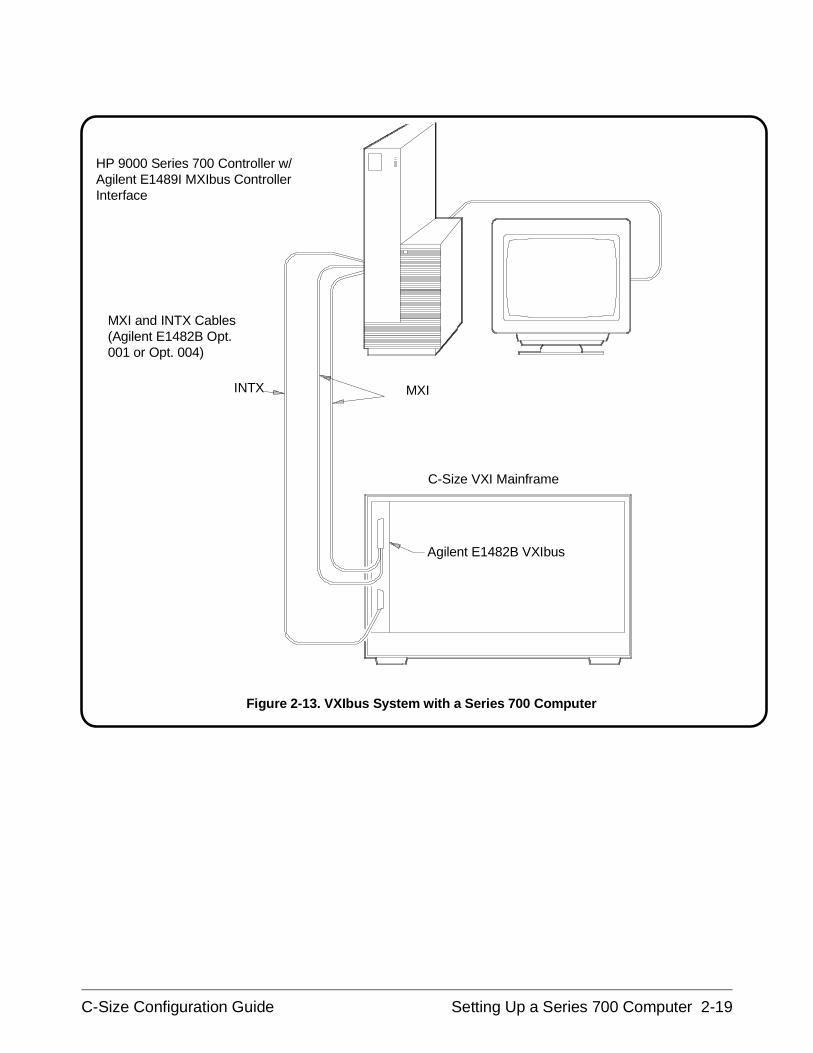
HP 9000 Series 700 Controller w/Agilent E1489I MXIbus ControllerInterface
Agilent E1482B VXIbus
C-Size VXI Mainframe
MXI and INTX Cables(Agilent E1482B Opt.001 or Opt. 004)
MXIINTX
Figure 2-13. VXIbus System with a Series 700 Computer
C-Size Configuration Guide Setting Up a Series 700 Computer 2-19
Series 700-1 : Set up the Agilent E1482B VXIbus Extender Module
The Agilent E1482B VXI-MXI module is factory configured for use inmainframe slot 0. Table 2-1 lists the factory (slot 0) settings. Verify themodule settings against Table 2-1 and Figure 2-14.
CAUTION STATIC ELECTRICITY. Static electricity is a major cause ofcomponent failure. To prevent damage to the electricalcomponents in the mainframe and plug-in modules, observeanti-static techniques whenever handling a module.
2-20 Setting Up a Series 700 Computer C-Size Configuration Guide
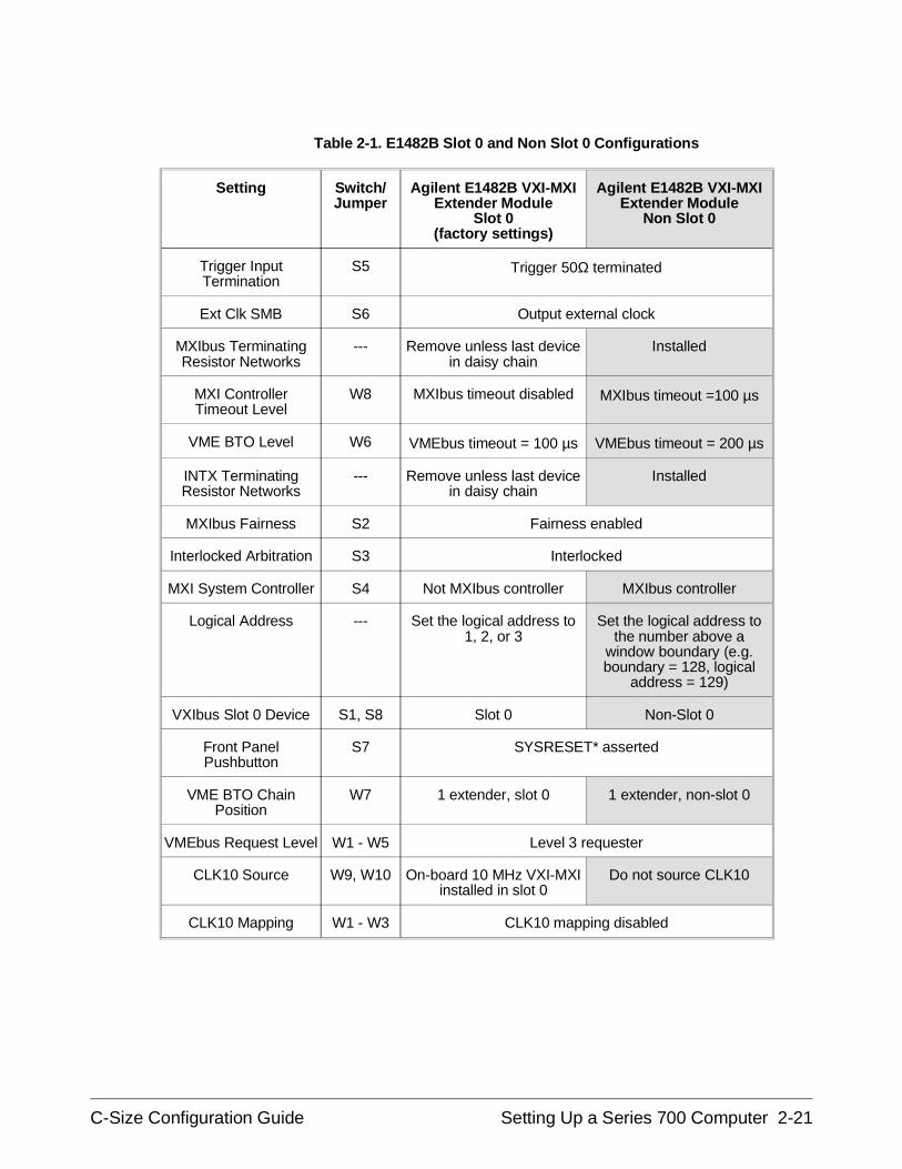
Setting Switch/Jumper
Agilent E1482B VXI-MXIExtender Module
Slot 0(factory settings)
Agilent E1482B VXI-MXIExtender Module
Non Slot 0
Trigger InputTermination
S5 Trigger 50Ω terminated
Ext Clk SMB S6 Output external clock
MXIbus TerminatingResistor Networks
--- Remove unless last devicein daisy chain
Installed
MXI ControllerTimeout Level
W8 MXIbus timeout disabled MXIbus timeout =100 µs
VME BTO Level W6 VMEbus timeout = 100 µs VMEbus timeout = 200 µs
INTX TerminatingResistor Networks
--- Remove unless last devicein daisy chain
Installed
MXIbus Fairness S2 Fairness enabled
Interlocked Arbitration S3 Interlocked
MXI System Controller S4 Not MXIbus controller MXIbus controller
Logical Address --- Set the logical address to1, 2, or 3
Set the logical address tothe number above a
window boundary (e.g.boundary = 128, logical
address = 129)
VXIbus Slot 0 Device S1, S8 Slot 0 Non-Slot 0
Front PanelPushbutton
S7 SYSRESET* asserted
VME BTO ChainPosition
W7 1 extender, slot 0 1 extender, non-slot 0
VMEbus Request Level W1 - W5 Level 3 requester
CLK10 Source W9, W10 On-board 10 MHz VXI-MXIinstalled in slot 0
Do not source CLK10
CLK10 Mapping W1 - W3 CLK10 mapping disabled
Table 2-1. E1482B Slot 0 and Non Slot 0 Configurations
C-Size Configuration Guide Setting Up a Series 700 Computer 2-21
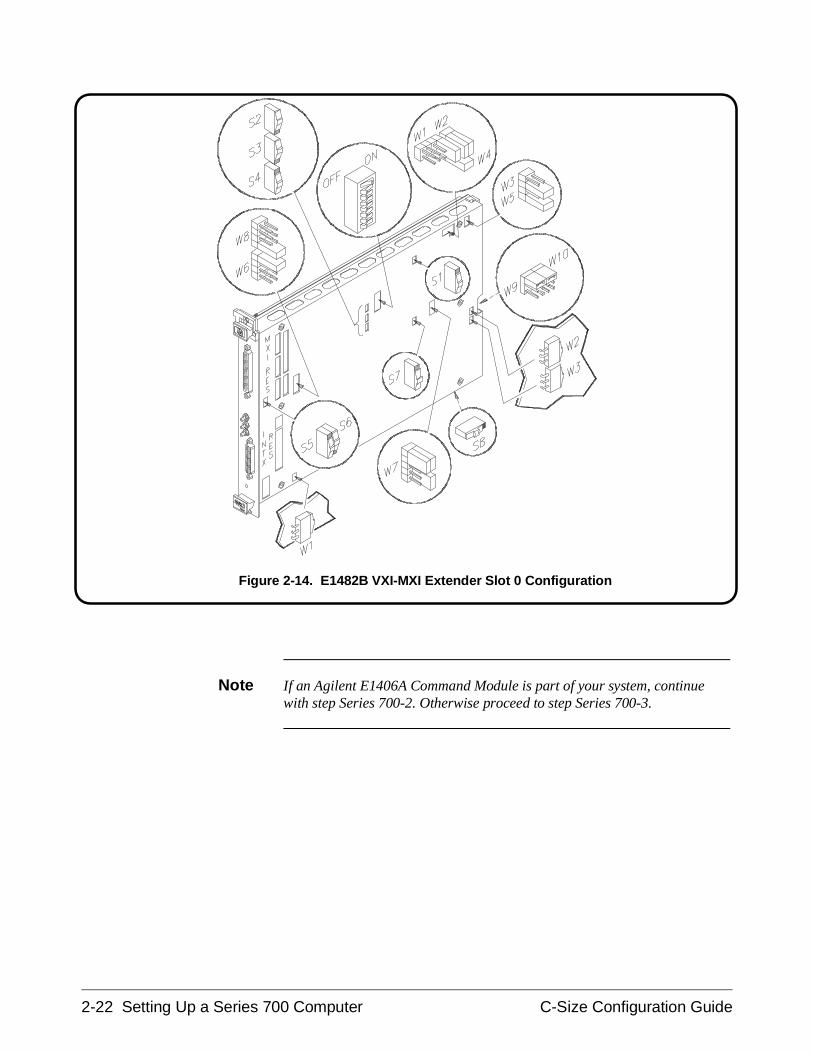
Note If an Agilent E1406A Command Module is part of your system, continuewith step Series 700-2. Otherwise proceed to step Series 700-3.
Figure 2-14. E1482B VXI-MXI Extender Slot 0 Configuration
2-22 Setting Up a Series 700 Computer C-Size Configuration Guide
Series 700-2 : Set Up the Agilent E1406A Command Module
If an Agilent E1406A Command Module is part of your Series 700/MXIbased VXIbus system, you must configure the Command Module for usewith the Series 700 computer and the Agilent E1482B VXIbus Extendermodule. This includes:
• setting the Command Module logical address so that it is a servant tothe Series 700
• setting the Command Module servant area so that it is thecommander of the system’s Agilent Technologies register-basedmodules
• setting the Command Module primary GPIB address
• disabling the Command Module’s slot 0 and system controllercapability
• disabling the Command Module’s VMEbus Time Out capability
In VXIbus systems with an HP Series 700 computer, Agilent E1482BMXIbus Extender, and a Agilent E1406A Command Module, thefollowing configuration is recommended:
– Series 700 (with the Agilent E1489I MXIbus ControllerInterface) is the resource manager
– Agilent E1482B MXIbus Extender is the slot 0 device
– Agilent E1406A Command Module is the commander to thesystem’s Agilent Technologies register-based modules
The resource manager and slot 0 functions and commander/servanthierarchy concepts are covered in Appendix A "Terms and Definitions".
C-Size Configuration Guide Setting Up a Series 700 Computer 2-23
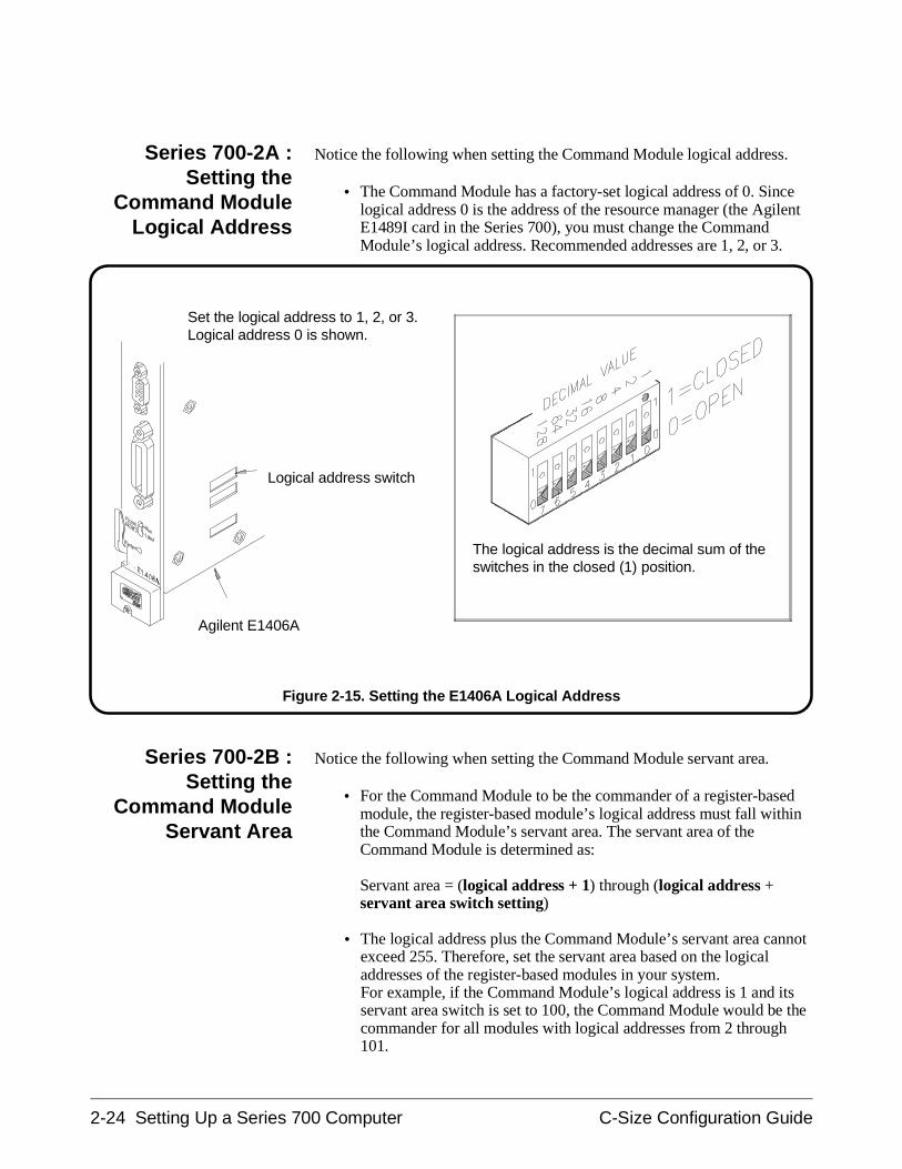
Series 700-2A :Setting the
Command ModuleLogical Address
Notice the following when setting the Command Module logical address.
• The Command Module has a factory-set logical address of 0. Sincelogical address 0 is the address of the resource manager (the AgilentE1489I card in the Series 700), you must change the CommandModule’s logical address. Recommended addresses are 1, 2, or 3.
Series 700-2B :Setting the
Command ModuleServant Area
Notice the following when setting the Command Module servant area.
• For the Command Module to be the commander of a register-basedmodule, the register-based module’s logical address must fall withinthe Command Module’s servant area. The servant area of theCommand Module is determined as:
Servant area = (logical address + 1) through (logical address +servant area switch setting)
• The logical address plus the Command Module’s servant area cannotexceed 255. Therefore, set the servant area based on the logicaladdresses of the register-based modules in your system. For example, if the Command Module’s logical address is 1 and itsservant area switch is set to 100, the Command Module would be thecommander for all modules with logical addresses from 2 through101.
Set the logical address to 1, 2, or 3.Logical address 0 is shown.
The logical address is the decimal sum of theswitches in the closed (1) position.
Agilent E1406A
Logical address switch
Figure 2-15. Setting the E1406A Logical Address
2-24 Setting Up a Series 700 Computer C-Size Configuration Guide
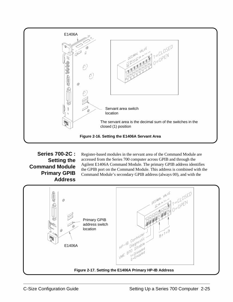
Series 700-2C :Setting the
Command ModulePrimary GPIB
Address
Register-based modules in the servant area of the Command Module areaccessed from the Series 700 computer across GPIB and through theAgilent E1406A Command Module. The primary GPIB address identifiesthe GPIB port on the Command Module. This address is combined with theCommand Module’s secondary GPIB address (always 00), and with the
The servant area is the decimal sum of the switches in theclosed (1) position
Servant area switchlocation
E1406A
Figure 2-16. Setting the E1406A Servant Area
E1406A
Primary GPIBaddress switchlocation
Figure 2-17. Setting the E1406A Primary HP-IB Address
C-Size Configuration Guide Setting Up a Series 700 Computer 2-25
Series 700 computer’s (GPIB) interface select code (typically 7), to formthe Command Module’s complete GPIB address.
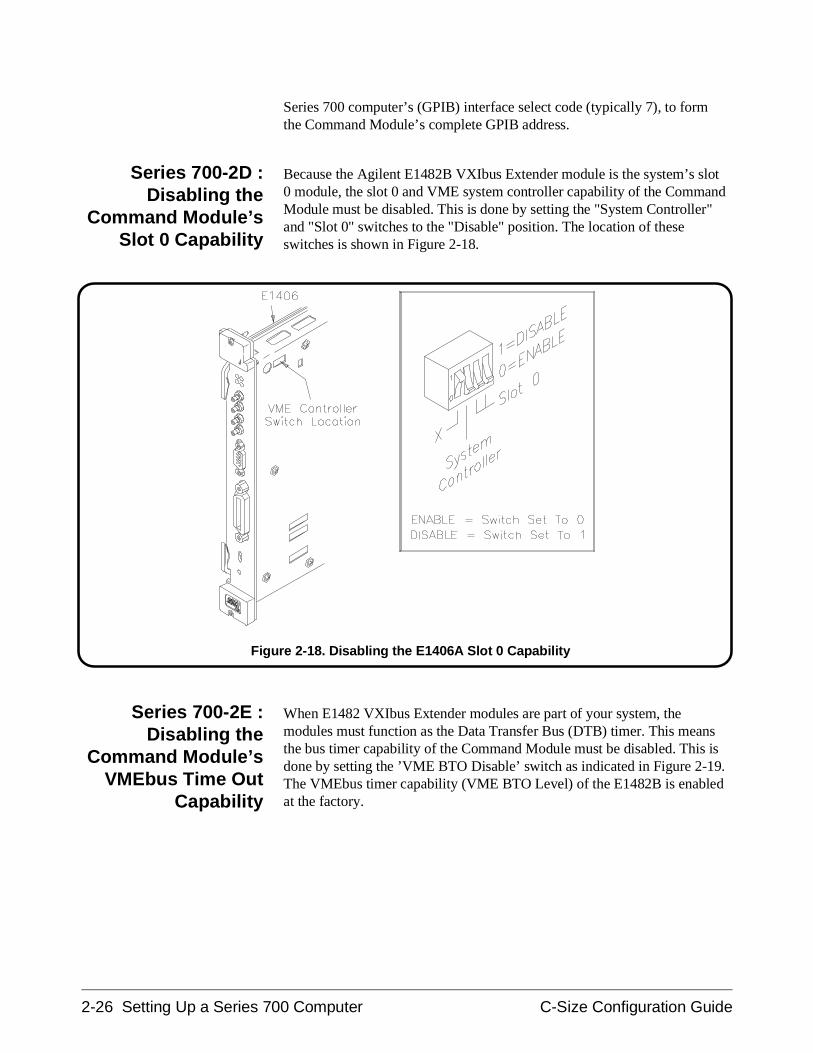
Series 700-2D :Disabling the
Command Module’sSlot 0 Capability
Because the Agilent E1482B VXIbus Extender module is the system’s slot0 module, the slot 0 and VME system controller capability of the CommandModule must be disabled. This is done by setting the "System Controller"and "Slot 0" switches to the "Disable" position. The location of theseswitches is shown in Figure 2-18.
Series 700-2E :Disabling the
Command Module’sVMEbus Time Out
Capability
When E1482 VXIbus Extender modules are part of your system, themodules must function as the Data Transfer Bus (DTB) timer. This meansthe bus timer capability of the Command Module must be disabled. This isdone by setting the ’VME BTO Disable’ switch as indicated in Figure 2-19.The VMEbus timer capability (VME BTO Level) of the E1482B is enabledat the factory.
Figure 2-18. Disabling the E1406A Slot 0 Capability
2-26 Setting Up a Series 700 Computer C-Size Configuration Guide
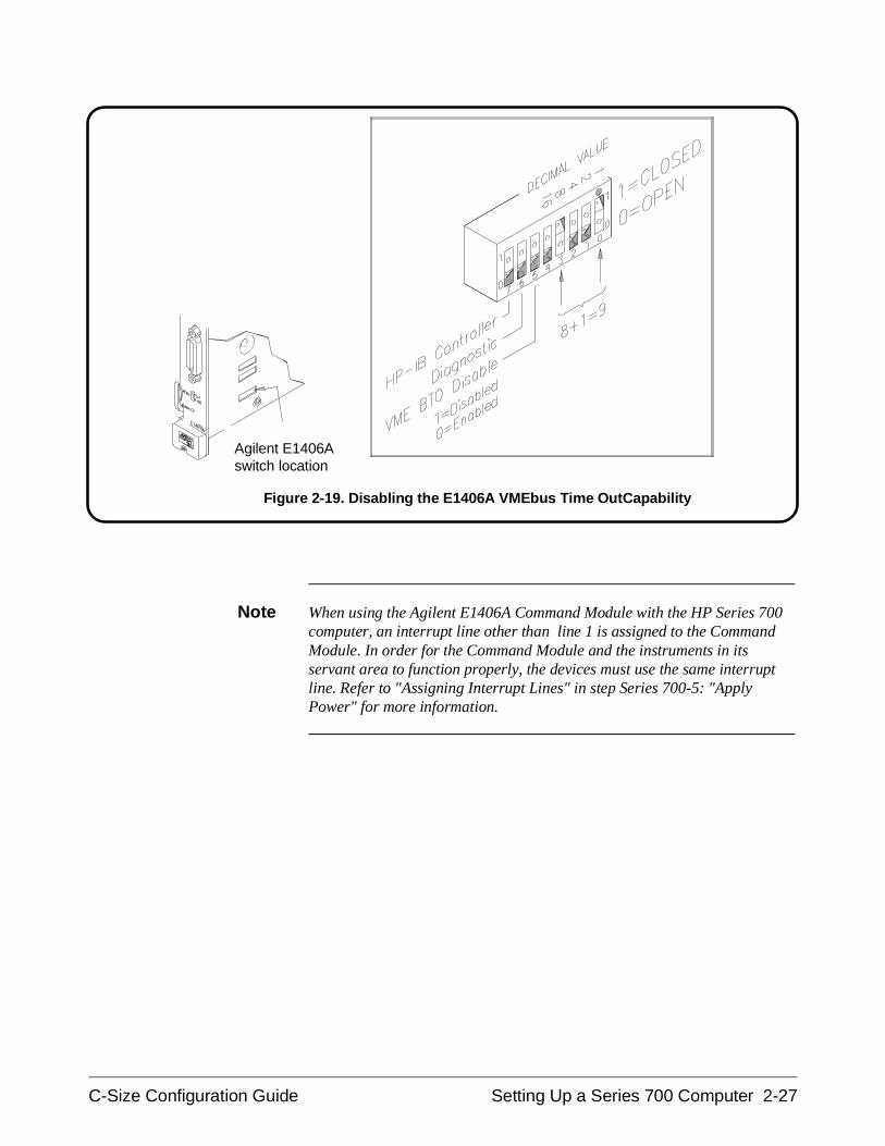
Note When using the Agilent E1406A Command Module with the HP Series 700computer, an interrupt line other than line 1 is assigned to the CommandModule. In order for the Command Module and the instruments in itsservant area to function properly, the devices must use the same interruptline. Refer to "Assigning Interrupt Lines" in step Series 700-5: "ApplyPower" for more information.
Agilent E1406Aswitch location
Figure 2-19. Disabling the E1406A VMEbus Time OutCapability
C-Size Configuration Guide Setting Up a Series 700 Computer 2-27
Series 700-3 : Install the Agilent E1482B Extender Module in theMainframe
Use the following procedure to install the Agilent E1482B VXIbusExtender Module into mainframe slot 0.
1. If the mainframe is on, turn it off.
2. Insert the module into the mainframe by aligning the top andbottom of the VXIbus extender module with the card guides insidethe mainframe. Slowly push the module into slot 0 until it seats inthe backplane connector.
3. Tighten the retaining screws on the top and bottom edges of themodule’s front panel.
Installing theE1406A Command
Module
Use the following procedure to install the Agilent E1406A CommandModule into slot 1 (when the Agilent E1482B module is installed in slot 0).
1. If the mainframe is on, turn it off.
2. Insert the Command Module into the mainframe by aligning the topand bottom of the card with the card guides inside the mainframe.Slowly push the module straight into the slot until it seats in thebackplane connectors. The front panel of the module should beeven with the front panel of the mainframe.
3. Tighten the retaining screws on the top and bottom edges of theCommand Module front panel.
2-28 Setting Up a Series 700 Computer C-Size Configuration Guide
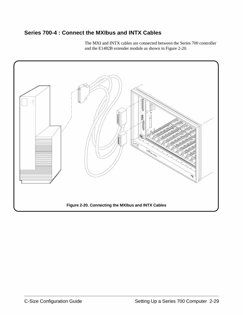
Series 700-4 : Connect the MXIbus and INTX Cables
The MXI and INTX cables are connected between the Series 700 controllerand the E1482B extender module as shown in Figure 2-20.
Figure 2-20. Connecting the MXIbus and INTX Cables
C-Size Configuration Guide Setting Up a Series 700 Computer 2-29
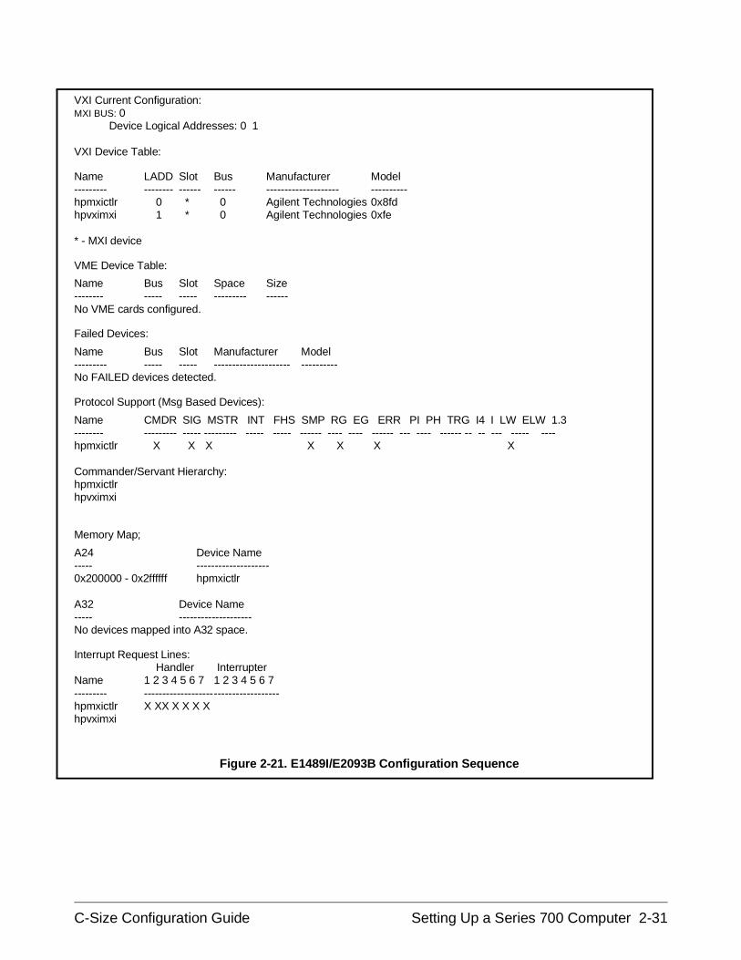
Series 700-5 : Apply Power
To verify that the E1482B VXIbus extender module and the MXIbus andINTX cables are correctly installed, turn on the mainframe. This starts thesystem resource manager function (ivxirm) provided by the Agilent E1489IMXIbus Controller Interface card and the Agilent E2093B SICL software.To view the contents of the configuration file (rsrcmgr.out) written to by theresource manager, type the following command:
/usr/pil/bin/ivxisc (HP-UX)
or
IVXISC (from the directory the resource manager executes from)
An example of the configuration file (sequence) with only the E1482Binstalled is shown in Figure 2-21.
2-30 Setting Up a Series 700 Computer C-Size Configuration Guide
VXI Current Configuration:MXI BUS: 0
Device Logical Addresses: 0 1
VXI Device Table:
Name LADD Slot Bus Manufacturer Model--------- -------- ------ ------ -------------------- ----------hpmxictlr 0 * 0 Agilent Technologies 0x8fdhpvximxi 1 * 0 Agilent Technologies 0xfe
* - MXI device
VME Device Table:
Name Bus Slot Space Size-------- ----- ----- --------- ------No VME cards configured.
Failed Devices:
Name Bus Slot Manufacturer Model--------- ----- ----- --------------------- ----------No FAILED devices detected.
Protocol Support (Msg Based Devices):
Name CMDR SIG MSTR INT FHS SMP RG EG ERR PI PH TRG I4 I LW ELW 1.3-------- --------- ----- --------- ----- ----- ------ ---- ---- ------ --- ---- ------ -- -- --- ----- ----hpmxictlr X X X X X X X
Commander/Servant Hierarchy:hpmxictlrhpvximxi
Memory Map;
A24 Device Name----- --------------------0x200000 - 0x2ffffff hpmxictlr
A32 Device Name----- --------------------No devices mapped into A32 space.
Interrupt Request Lines: Handler Interrupter
Name 1 2 3 4 5 6 7 1 2 3 4 5 6 7--------- -------------------------------------hpmxictlr X XX X X X Xhpvximxi
Figure 2-21. E1489I/E2093B Configuration Sequence
C-Size Configuration Guide Setting Up a Series 700 Computer 2-31
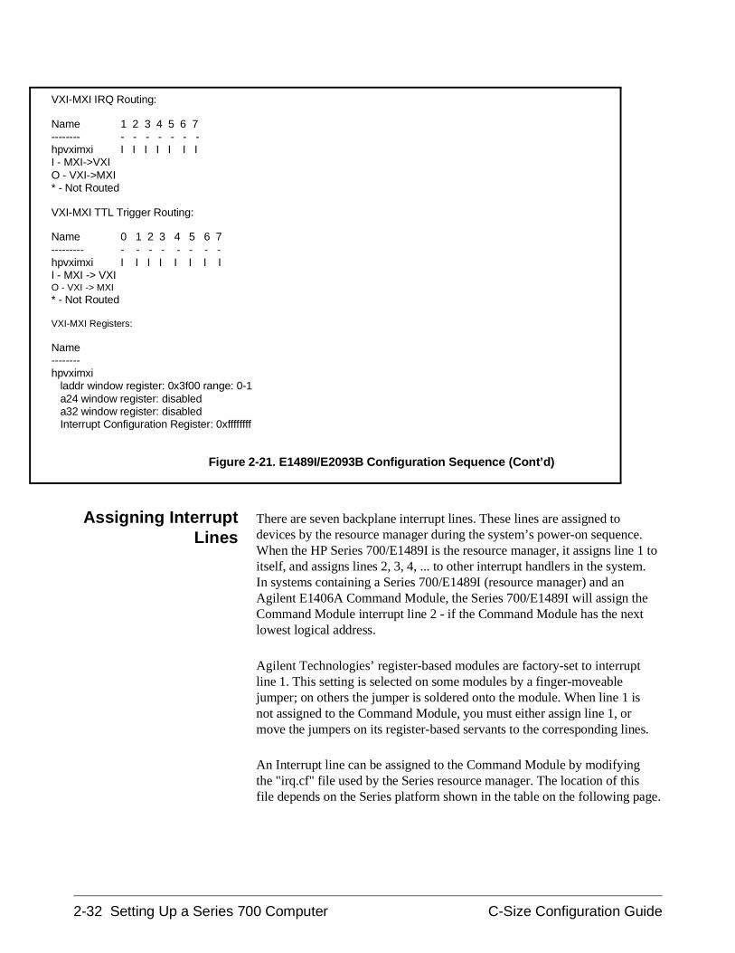
Assigning InterruptLines
There are seven backplane interrupt lines. These lines are assigned todevices by the resource manager during the system’s power-on sequence.When the HP Series 700/E1489I is the resource manager, it assigns line 1 toitself, and assigns lines 2, 3, 4, ... to other interrupt handlers in the system.In systems containing a Series 700/E1489I (resource manager) and an Agilent E1406A Command Module, the Series 700/E1489I will assign theCommand Module interrupt line 2 - if the Command Module has the nextlowest logical address.
Agilent Technologies’ register-based modules are factory-set to interruptline 1. This setting is selected on some modules by a finger-moveablejumper; on others the jumper is soldered onto the module. When line 1 isnot assigned to the Command Module, you must either assign line 1, ormove the jumpers on its register-based servants to the corresponding lines.
An Interrupt line can be assigned to the Command Module by modifyingthe "irq.cf" file used by the Series resource manager. The location of thisfile depends on the Series platform shown in the table on the following page.
VXI-MXI IRQ Routing:
Name 1 2 3 4 5 6 7-------- - - - - - - -hpvximxi I I I I I I II - MXI->VXIO - VXI->MXI* - Not Routed
VXI-MXI TTL Trigger Routing:
Name 0 1 2 3 4 5 6 7--------- - - - - - - - -hpvximxi I I I I I I I II - MXI -> VXIO - VXI -> MXI* - Not Routed
VXI-MXI Registers:
Name--------hpvximxi laddr window register: 0x3f00 range: 0-1 a24 window register: disabled a32 window register: disabled Interrupt Configuration Register: 0xffffffff
Figure 2-21. E1489I/E2093B Configuration Sequence (Cont’d)
2-32 Setting Up a Series 700 Computer C-Size Configuration Guide
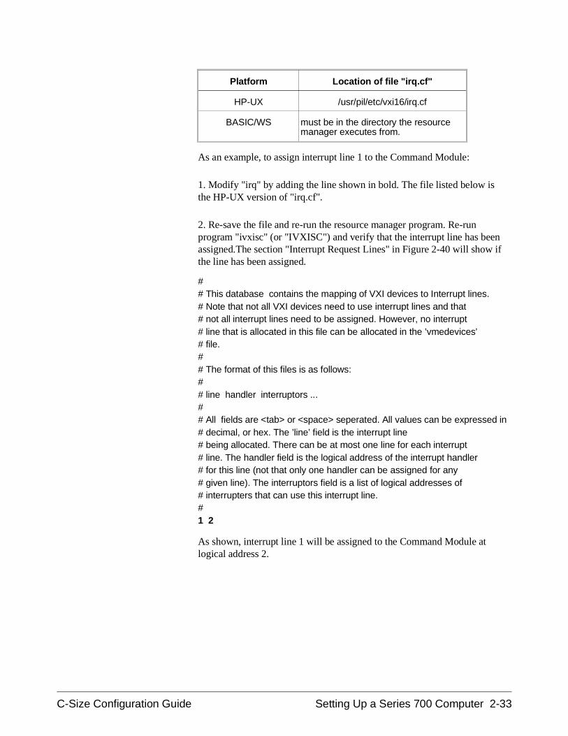
Platform Location of file "irq.cf"
HP-UX /usr/pil/etc/vxi16/irq.cf
BASIC/WS must be in the directory the resourcemanager executes from.
As an example, to assign interrupt line 1 to the Command Module:
1. Modify "irq" by adding the line shown in bold. The file listed below isthe HP-UX version of "irq.cf".
2. Re-save the file and re-run the resource manager program. Re-runprogram "ivxisc" (or "IVXISC") and verify that the interrupt line has beenassigned.The section "Interrupt Request Lines" in Figure 2-40 will show ifthe line has been assigned.
## This database contains the mapping of VXI devices to Interrupt lines.# Note that not all VXI devices need to use interrupt lines and that# not all interrupt lines need to be assigned. However, no interrupt# line that is allocated in this file can be allocated in the ’vmedevices’# file.## The format of this files is as follows:## line handler interruptors ...## All fields are <tab> or <space> seperated. All values can be expressed in# decimal, or hex. The ’line’ field is the interrupt line# being allocated. There can be at most one line for each interrupt# line. The handler field is the logical address of the interrupt handler# for this line (not that only one handler can be assigned for any# given line). The interruptors field is a list of logical addresses of# interrupters that can use this interrupt line.# 1 2
As shown, interrupt line 1 will be assigned to the Command Module atlogical address 2.
C-Size Configuration Guide Setting Up a Series 700 Computer 2-33
Series 700-6 : Where To Go Next
Once you have installed the Agilent E1482 VXIbus extender module,continue with one of the following procedures:
If you have multiple mainframes connected via MXIbus:
• "Procedure 3: Set Up Your System for Multiple Mainframes"
If you are using one mainframe:
• "Procedure 4: Configure and Install Instruments"
2-34 Setting Up a Series 700 Computer C-Size Configuration Guide
Setting Up an Embedded V743 Controller
This procedure describes the system configuration and steps necessary foran Agilent E1497A V743/64 or Agilent E1498A V743/100 EmbeddedController to be used as a VXI instrument controller. The steps in thisprocedure include:
• V743-1 : The V743 VXI Configuration
• V743-2 : Set Up the Agilent E1406A Command Module
• V743-3 : Install the V743 Controller in the Mainframe
• V743-4 : Apply Power
• V743-5 : Where To Go Next
V743-1 : The V743 Configuration
As shown in Figure 2-31, the V743 controller requires the followingsoftware package:
Agilent E2091C - Standard Instrument Control Library (SICL) HP-UX 9.05(version C.03.02)
The V743 with the Agilent E2091C software provides the system’s resourcemanager functionality. The V743 also provides the system’s slot 0 functionswhen the controller is installed in mainframe slot 0.
Communication between the V743 controller and the instruments in themainframe is across the VXIbus backplane, or across GPIB through the Agilent E1406A Command Module.
Note This procedure lists the V743 VXI configuration and covers installation ofthe controller into a VXI mainframe. The procedure does not coverinstallation of the Agilent E2091C software. Refer to the softwaredocumentation for software installation information.
C-Size Configuration Guide Setting Up an Embedded V743 Controller 2-35
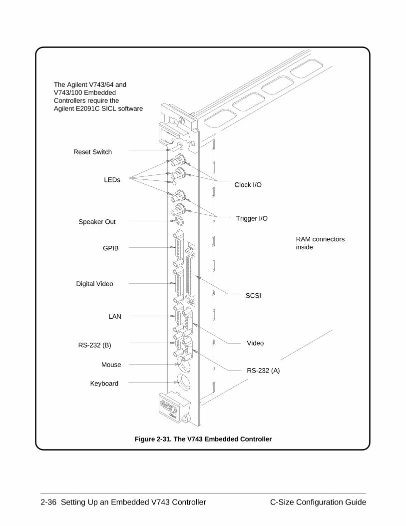
RAM connectorsinside
Reset Switch
LEDs
Speaker Out
GPIB
Clock I/O
Trigger I/O
Digital Video
SCSI
LAN
VideoRS-232 (B)
RS-232 (A)Mouse
Keyboard
The Agilent V743/64 andV743/100 EmbeddedControllers require the Agilent E2091C SICL software
Figure 2-31. The V743 Embedded Controller
2-36 Setting Up an Embedded V743 Controller C-Size Configuration Guide
The V743 LogicalAddress andServant Area
The following pertains to the V743 logical address and servant area:
• The V743 controller has a logical address of 0 and a servant area of255. These values are stored in software and cannot be changed.
• With a logical address of 0, the V743 is the VXI system’s resourcemanager. It is recommended that the V743 be installed in mainframeslot 0 so that it also functions as the system’s slot 0 device.
• With its logical address set at 0 and its servant area set at 255, theV743 controller is the system’s top level commander. However, acommander can be a servant to another commander thus forming ahierarchial system. Servants in the servant area of the "lower-level"commander are controlled by the lower-level commander.
• The V743 should be the commander of the system’s message-basedmodules (including other commanders). This enables themessage-based modules to be programmed at higher speeds acrossthe VXIbus backplane. A commander such as the Agilent E1406ACommand Module should be the commander for the system’sAgilent Technologies register-based modules. This enables theregister-based modules to be programmed with SCPI commands viathe Command Module.
V743-2 : Set Up the Agilent E1406A Command Module
Note If an Agilent E1406A Command Module is part of your system, continuewith Step V743-2. Otherwise, proceed to step V743-3.
When an embedded controller such as the Agilent E1497A V743/64 orAgilent E1498A V743/100 and a Agilent E1406A Command Module arepart of your VXIbus system, you must configure the Command Module foruse with the V743. This includes:
• setting the Command Module logical address so that it is a servant tothe V743
• setting the Command Module servant area so that it is thecommander of the system’s Agilent Technologies register-basedmodules
• setting the Command Module primary GPIB address
• disabling the Command Module’s slot 0 and system controllercapability
C-Size Configuration Guide Setting Up an Embedded V743 Controller 2-37
In VXIbus systems with a V743 controller and a Agilent E1406ACommand Module, the V743 must function as the resource manager sinceits logical address is fixed at 0. The V743 should be installed in slot 0 tofunction as the system’s slot 0 device. The E1406A Command Module isthen a servant of the V743.
The resource manager and slot 0 functions, and the commander/servanthierarchy concepts are covered in Appendix A "Terms and Definitions".
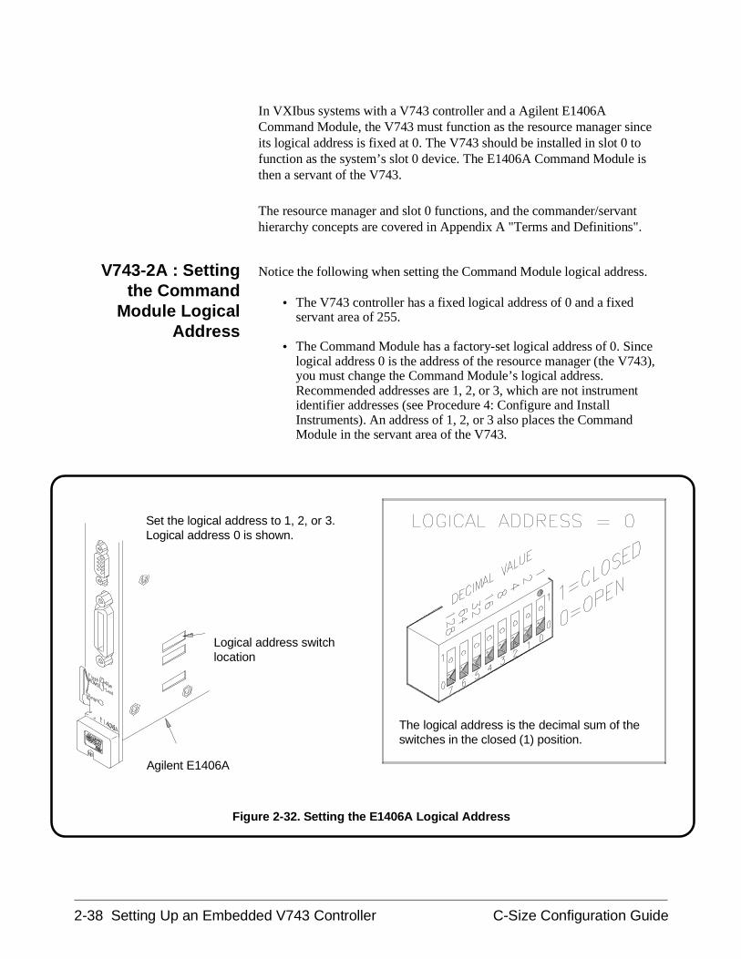
V743-2A : Settingthe Command
Module LogicalAddress
Notice the following when setting the Command Module logical address.
• The V743 controller has a fixed logical address of 0 and a fixedservant area of 255.
• The Command Module has a factory-set logical address of 0. Sincelogical address 0 is the address of the resource manager (the V743),you must change the Command Module’s logical address.Recommended addresses are 1, 2, or 3, which are not instrumentidentifier addresses (see Procedure 4: Configure and InstallInstruments). An address of 1, 2, or 3 also places the CommandModule in the servant area of the V743.
Set the logical address to 1, 2, or 3.Logical address 0 is shown.
The logical address is the decimal sum of theswitches in the closed (1) position.
Agilent E1406A
Logical address switchlocation
Figure 2-32. Setting the E1406A Logical Address
2-38 Setting Up an Embedded V743 Controller C-Size Configuration Guide
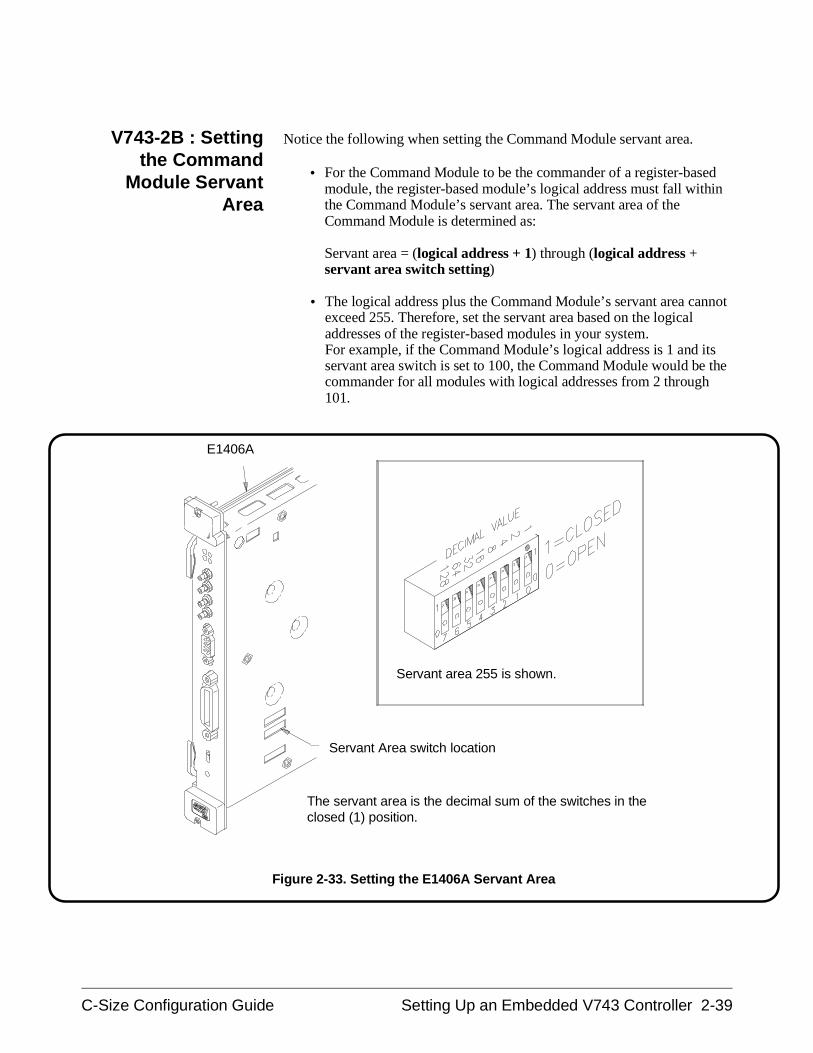
V743-2B : Settingthe Command
Module ServantArea
Notice the following when setting the Command Module servant area.
• For the Command Module to be the commander of a register-basedmodule, the register-based module’s logical address must fall withinthe Command Module’s servant area. The servant area of theCommand Module is determined as:
Servant area = (logical address + 1) through (logical address +servant area switch setting)
• The logical address plus the Command Module’s servant area cannotexceed 255. Therefore, set the servant area based on the logicaladdresses of the register-based modules in your system. For example, if the Command Module’s logical address is 1 and itsservant area switch is set to 100, the Command Module would be thecommander for all modules with logical addresses from 2 through101.
Servant area 255 is shown.
The servant area is the decimal sum of the switches in theclosed (1) position.
E1406A
Servant Area switch location
Figure 2-33. Setting the E1406A Servant Area
C-Size Configuration Guide Setting Up an Embedded V743 Controller 2-39
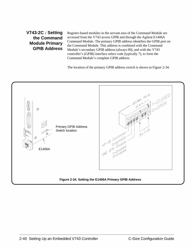
V743-2C : Settingthe Command
Module PrimaryGPIB Address
Register-based modules in the servant area of the Command Module areaccessed from the V743 across GPIB and through the Agilent E1406ACommand Module. The primary GPIB address identifies the GPIB port onthe Command Module. This address is combined with the CommandModule’s secondary GPIB address (always 00), and with the V743controller’s (GPIB) interface select code (typically 7), to form theCommand Module’s complete GPIB address.
The location of the primary GPIB address switch is shown in Figure 2-34.
E1406A
Primary GPIB AddressSwitch location
Figure 2-34. Setting the E1406A Primary GPIB Address
2-40 Setting Up an Embedded V743 Controller C-Size Configuration Guide
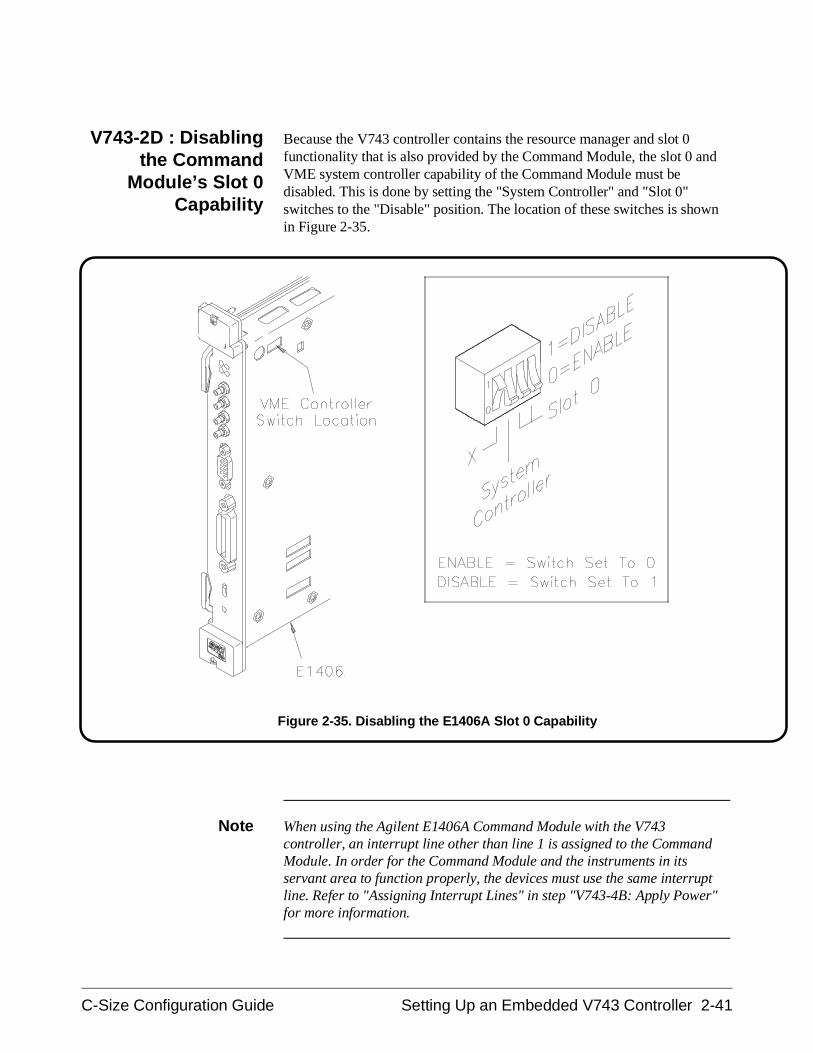
V743-2D : Disablingthe Command
Module’s Slot 0Capability
Because the V743 controller contains the resource manager and slot 0functionality that is also provided by the Command Module, the slot 0 andVME system controller capability of the Command Module must bedisabled. This is done by setting the "System Controller" and "Slot 0"switches to the "Disable" position. The location of these switches is shownin Figure 2-35.
Note When using the Agilent E1406A Command Module with the V743controller, an interrupt line other than line 1 is assigned to the CommandModule. In order for the Command Module and the instruments in itsservant area to function properly, the devices must use the same interruptline. Refer to "Assigning Interrupt Lines" in step "V743-4B: Apply Power"for more information.
Figure 2-35. Disabling the E1406A Slot 0 Capability
C-Size Configuration Guide Setting Up an Embedded V743 Controller 2-41
V743-3 : Install the V743 Controller in the Mainframe
Use the following procedure to install the V743 controller into mainframeslot 0.
1. If the mainframe is on, turn it off.
2. Insert the V743 into the mainframe by aligning the top and bottomof the controller with the card guides inside the mainframe. Slowlypush the V743 into slot 0 until it seats in the backplane connectors.
3. Tighten the retaining screws on the top and bottom of thecontroller’s front panel.
Note If your system contains an Agilent E1406A Command Module, continuethrough step V743-3. Otherwise, continue with step V743-4.
Note For information on connecting the monitor, keyboard, mouse, and externalperipherals, refer to the "Model V743 VXI Controller Installation Guide".Step V743-4 of this procedure assumes that a keyboard and monitor havebeen connected.
2-42 Setting Up an Embedded V743 Controller C-Size Configuration Guide
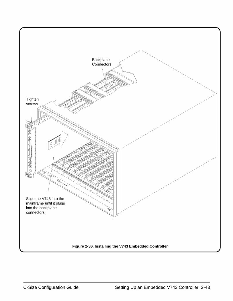
BackplaneConnectors
Tighten screws
Slide the V743 into themainframe until it plugsinto the backplaneconnectors
Figure 2-36. Installing the V743 Embedded Controller
C-Size Configuration Guide Setting Up an Embedded V743 Controller 2-43
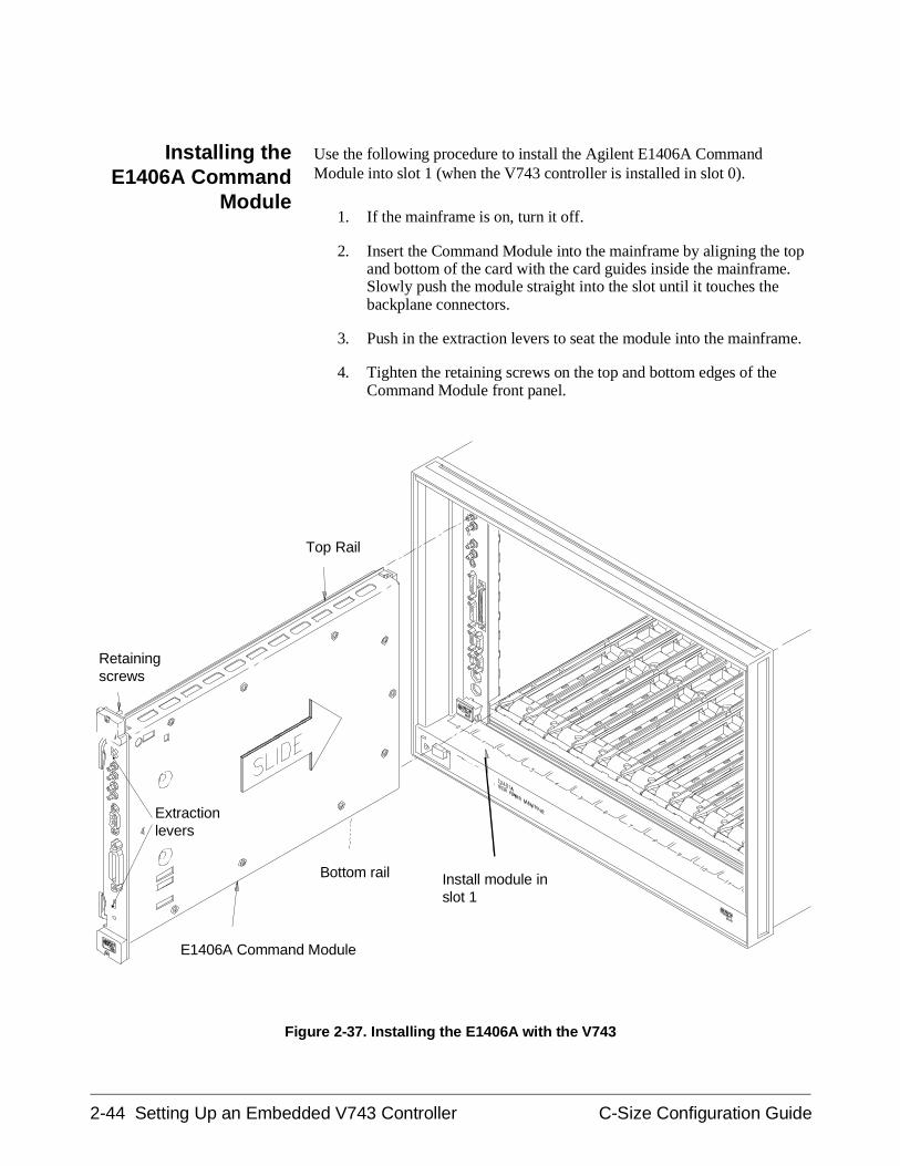
Installing theE1406A Command
Module
Use the following procedure to install the Agilent E1406A CommandModule into slot 1 (when the V743 controller is installed in slot 0).
1. If the mainframe is on, turn it off.
2. Insert the Command Module into the mainframe by aligning the topand bottom of the card with the card guides inside the mainframe.Slowly push the module straight into the slot until it touches thebackplane connectors.
3. Push in the extraction levers to seat the module into the mainframe.
4. Tighten the retaining screws on the top and bottom edges of theCommand Module front panel.
Top Rail
Retainingscrews
Bottom rail Install module inslot 1
E1406A Command Module
Extractionlevers
Figure 2-37. Installing the E1406A with the V743
2-44 Setting Up an Embedded V743 Controller C-Size Configuration Guide
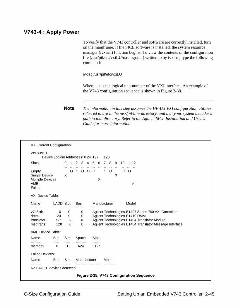
V743-4 : Apply Power
To verify that the V743 controller and software are correctly installed, turnon the mainframe. If the SICL software is installed, the system resourcemanager (ivxirm) function begins. To view the contents of the configurationfile (/usr/pil/etc/vxiLU/rsrcmgr.out) written to by ivxirm, type the followingcommand:
ivxisc /usr/pil/etc/vxiLU
Where LU is the logical unit number of the VXI interface. An example ofthe V743 configuration sequence is shown in Figure 2-38.
Note The information in this step assumes the HP-UX VXI configuration utilitiesreferred to are in the /usr/pil/bin/ directory, and that your system includes apath to that directory. Refer to the Agilent SICL Installation and User’sGuide for more information.
VXI Current Configuration:
VXI BUS: 0Device Logical Addresses: 0 24 127 128
Slots: 0 1 2 3 4 5 6 7 8 9 10 11 12-- -- -- -- -- -- -- -- -- -- -- -- --
Empty O O O O O O O O O Single Device X XMultiple Devices XVME VFailed
VXI Device Table:
Name LADD Slot Bus Manufacturer Model--------- -------- ------ ------ -------------------- ----------v743ctlr 0 0 0 Agilent Technologies E1497 Series 700 VXI Controllerdmm 24 9 0 Agilent Technologies E1410 DMMtranslator 127 6 0 Agilent Technologies E1404 Translator Modulemsgtrans 128 6 0 Agilent Technologies E1404 Translator Message Interface
VME Device Table:
Name Bus Slot Space Size-------- ----- ----- --------- ------memdev 0 12 A24 512K
Failed Devices:
Name Bus Slot Manufacturer Model--------- ----- ----- --------------------- ----------No FAILED devices detected.
Figure 2-38. V743 Configuration Sequence
C-Size Configuration Guide Setting Up an Embedded V743 Controller 2-45
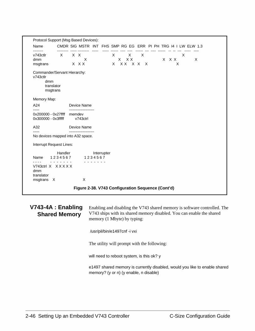
V743-4A : EnablingShared Memory
Enabling and disabling the V743 shared memory is software controlled. TheV743 ships with its shared memory disabled. You can enable the sharedmemory (1 Mbyte) by typing:
/usr/pil/bin/e1497cnf -i vxi
The utility will prompt with the following:
will need to reboot system, is this ok? y
e1497 shared memory is currently disabled, would you like to enable sharedmemory? (y or n) (y enable, n disable)
Protocol Support (Msg Based Devices):
Name CMDR SIG MSTR INT FHS SMP RG EG ERR PI PH TRG I4 I LW ELW 1.3-------- --------- ----- --------- ----- ----- ------ ---- ---- ------ --- ---- ------ -- -- --- ----- ----v743ctlr X X X X X X Xdmm X X X X X X X Xmsgtrans X X X X X X X X X X
Commander/Servant Hierarchy:v743ctlr
dmmtranslatormsgtrans
Memory Map:
A24 Device Name----- --------------------0x200000 - 0x27ffff memdev0x300000 - 0x3fffff v743ctrl
A32 Device Name----- --------------------No devices mapped into A32 space.
Interrupt Request Lines:
Handler InterrupterName 1 2 3 4 5 6 7 1 2 3 4 5 6 7- - - - - - - - - - - - - - - - - -V743ctrl X X X X X Xdmmtranslatormsgtrans X X
Figure 2-38. V743 Configuration Sequence (Cont’d)
2-46 Setting Up an Embedded V743 Controller C-Size Configuration Guide
The V743 shared memory is mapped into VXI A24 address space. Thus, thememory is accessible from the V743 and from other devices such as theAgilent E1406A Command Module. Notice that the V743 accesses thememory as SHARED, and not from the A24 memory map (Figure 2-38).
V743-4B :Assigning Interrupt
Lines
There are seven VME backplane interrupt lines. These lines are assigned todevices by the resource manager during the system’s power-on or resetsequence. When the V743 controller is the resource manager, it assigns line1 to itself, and assigns lines 2 through 7 to other interrupt handlers in thesystem. In systems containing a V743 controller (resource manager) and anAgilent E1406A Command Module, the V743 will, by default, assign theCommand Module interrupt line 2 - if the Command Module has the nextlowest logical address.
Agilent Technologies’ register-based modules are factory-set to interruptline 1. This setting is selected on some modules by a finger-moveablejumper; on others the jumper is soldered onto the module. When line 1 isnot assigned to the Command Module, you must either assign line 1, ormove the jumpers on its register-based servants to the corresponding lines.
An interrupt line can be assigned to the Command Module by modifying the/usr/pil/etc/vxiLU/irq.cf configuration file. The location of this file dependson the SICL logical unit number assigned to the VXI interface (default =24). For example:
SICL Logical Unit Location of file "irq.cf"
24 /usr/pil/etc/vxi24/irq.cf
Example - Assigningan Interrupt Line
As an example, to assign interrupt line 1 to the Command Module at logicaladdress 2:
1. Modify irq.cf by adding the line shown in bold on the next page.
2. Re-save the file and re-run the resource manager utility ivxirm. Run ivxisc/usr/pil/etc/vxi24 and verify that the interrupt line has been assigned.(The"Interrupt Request Lines" section of the configuration sequence will show ifthe line has been assigned.)
C-Size Configuration Guide Setting Up an Embedded V743 Controller 2-47
## This database contains the mapping of VXI devices to Interrupt lines.# Note that not all VXI devices need to use interrupt lines and that# not all interrupt lines need to be assigned. However, no interrupt# line that is allocated in this file can be allocated in the ’vmedevices’# file.## The format of this files is as follows:## line handler interruptors ...## All fields are <tab> or <space> seperated. All values can be #expressed in# decimal, or hex. The ’line’ field is the interrupt line# being allocated. There can be at most one line for each interrupt# line. The handler field is the logical address of the interrupt handler# for this line (not that only one handler can be assigned for any# given line). The interruptors field is a list of logical addresses of# interrupters that can use this interrupt line.# 1 2
As shown, interrupt line 1 will be assigned to the Command Module atlogical address 2.
V743-5 : Where To Go Next
Once you have installed the V743 controller, continue with one of thefollowing procedures:
If you have multiple mainframes connected via MXIbus:
• "Procedure 3: Set Up Your System for Multiple Mainframes"
If you are using one mainframe:
• "Procedure 4: Configure and Install Instruments"
2-48 Setting Up an Embedded V743 Controller C-Size Configuration Guide
Setting Up an Embedded RADI-EPC7 486 Computer
This procedure explains how to set up and install an Agilent 75000 Series CVXIbus system equipped with an Embedded Agilent RADI-EPC7Computer. The steps in this procedure consists of the following:
• EPC7-1 : Set the EPC7 as Slot 0 Device
• EPC7-1A : Set the EPC7 as Non-Slot 0 Device if Using MultipleMainframes
• EPC7-2 : Install the EPC7 into the Mainframe
• EPC7-3 : Install EXM Expansion Modules
• EPC7-4 : Configure the Command Module to Work With the EPC7
• EPC7-5 : Connect Interface Cables
• EPC7-6 : Apply Power
• EPC7-7 : Where To Go Next
The embedded Agilent RADI-EPC7 computer is shipped from the factorywith software already installed. EPConnect is a set of system developmenttools that can be used on the VXIbus system containing one or more AgilentRADI-EPC modules. One of the tools is the Start-Up Resource Manager(SURM). The SURM performs the required functions of the resourcemanager.
If you need information on terms used in this manual, see Appendix A,"Terms and Definitions."
CAUTION STATIC ELECTRICITY. Static electricity is a major cause ofcomponent failure. To prevent damage to the electricalcomponents in the mainframe and plug-in modules, observeanti-static techniques whenever handling a module.
NOTE The EPC7 contains a hard disk. Please handle it with care. Avoid jarringthe unit while it is in operation, and do not use excessive force wheninserting or removing the EPC7 in a VXIbus mainframe.
C-Size Configuration Guide Setting Up an Embedded RADI-EPC7 Computer 2-49
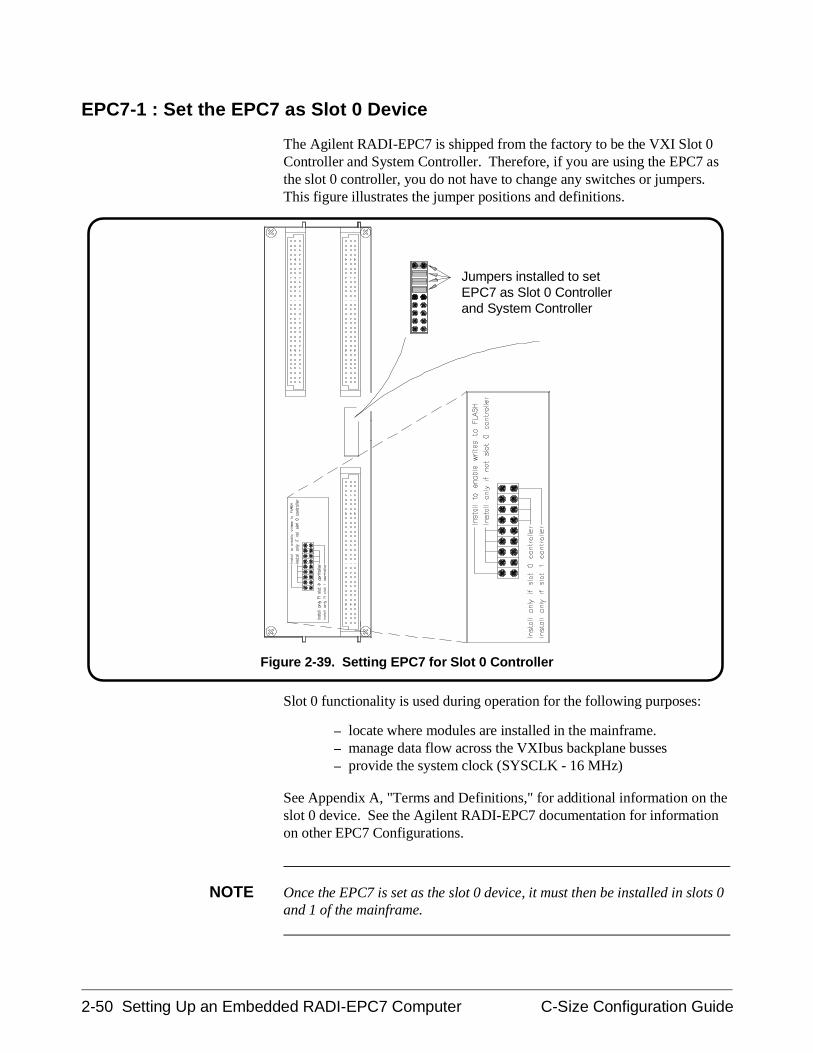
EPC7-1 : Set the EPC7 as Slot 0 Device
The Agilent RADI-EPC7 is shipped from the factory to be the VXI Slot 0Controller and System Controller. Therefore, if you are using the EPC7 asthe slot 0 controller, you do not have to change any switches or jumpers.This figure illustrates the jumper positions and definitions.
Slot 0 functionality is used during operation for the following purposes:
– locate where modules are installed in the mainframe.– manage data flow across the VXIbus backplane busses– provide the system clock (SYSCLK - 16 MHz)
See Appendix A, "Terms and Definitions," for additional information on theslot 0 device. See the Agilent RADI-EPC7 documentation for informationon other EPC7 Configurations.
NOTE Once the EPC7 is set as the slot 0 device, it must then be installed in slots 0and 1 of the mainframe.
Jumpers installed to setEPC7 as Slot 0 Controllerand System Controller
Figure 2-39. Setting EPC7 for Slot 0 Controller
2-50 Setting Up an Embedded RADI-EPC7 Computer C-Size Configuration Guide
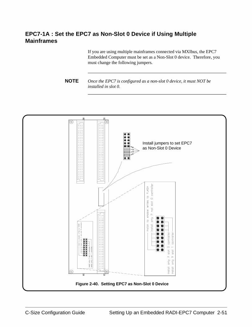
EPC7-1A : Set the EPC7 as Non-Slot 0 Device if Using MultipleMainframes
If you are using multiple mainframes connected via MXIbus, the EPC7Embedded Computer must be set as a Non-Slot 0 device. Therefore, youmust change the following jumpers.
NOTE Once the EPC7 is configured as a non-slot 0 device, it must NOT beinstalled in slot 0.
Install jumpers to set EPC7as Non-Slot 0 Device
Figure 2-40. Setting EPC7 as Non-Slot 0 Device
C-Size Configuration Guide Setting Up an Embedded RADI-EPC7 Computer 2-51

EPC7-2 : Install the EPC7 into the Mainframe
Use the following procedure to install the Agilent RADI-EPC7 EmbeddedComputer into slots 0 and 1 of the mainframe.
NOTE If you are using multiple mainframes via MXIbus, install the VXI-MXImodule into slot 0 (according to "Procedure 3 : Set Up Your System forMultiple Mainframes") and the EPC7 into slots 1 and 2.
1. Turn off mainframe power by pressing the button in the lower leftcorner of the mainframe.
2. Insert the module into the mainframe by aligning the top andbottom of the EPC7 with the card guides inside the mainframe.Slowly push the EPC7 straight into the slots until it seats in thebackplane receptacles. The front panel of the EPC7 should be evenwith the front panel of the mainframe.
3. Tighten the retaining screws on the top and bottom edges of thefront panel.
NOTE The EPC7 has a front panel key that prevents its insertion next to certainother types of modules. This is done to prevent problems associated withincompatible signal levels on the VXI daisy-chained Local Bus. See theAgilent RADI-EPC7 documentation for more information.
2-52 Setting Up an Embedded RADI-EPC7 Computer C-Size Configuration Guide
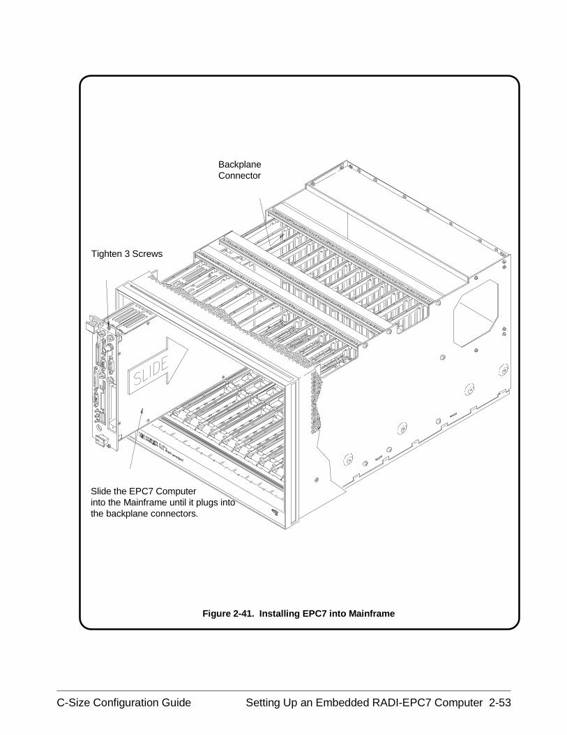
BackplaneConnector
Tighten 3 Screws
Slide the EPC7 Computerinto the Mainframe until it plugs intothe backplane connectors.
Figure 2-41. Installing EPC7 into Mainframe
C-Size Configuration Guide Setting Up an Embedded RADI-EPC7 Computer 2-53
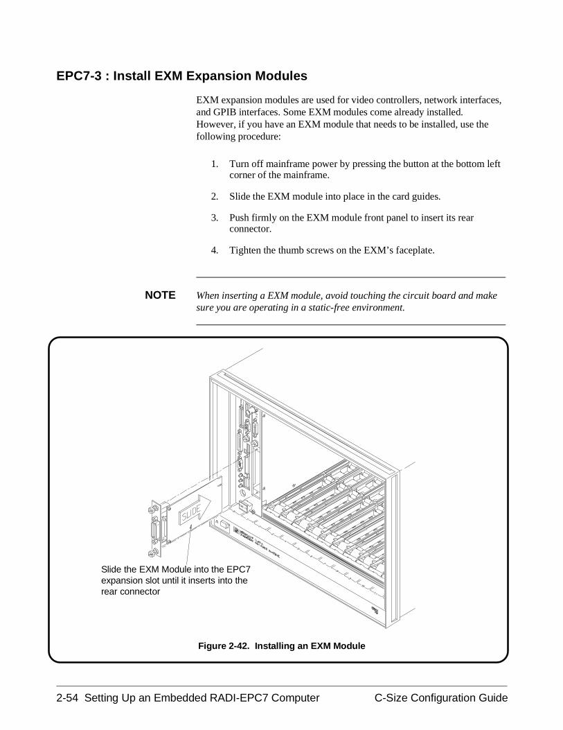
EPC7-3 : Install EXM Expansion Modules
EXM expansion modules are used for video controllers, network interfaces,and GPIB interfaces. Some EXM modules come already installed.However, if you have an EXM module that needs to be installed, use thefollowing procedure:
1. Turn off mainframe power by pressing the button at the bottom leftcorner of the mainframe.
2. Slide the EXM module into place in the card guides.
3. Push firmly on the EXM module front panel to insert its rearconnector.
4. Tighten the thumb screws on the EXM’s faceplate.
NOTE When inserting a EXM module, avoid touching the circuit board and makesure you are operating in a static-free environment.
Slide the EXM Module into the EPC7expansion slot until it inserts into therear connector
Figure 2-42. Installing an EXM Module
2-54 Setting Up an Embedded RADI-EPC7 Computer C-Size Configuration Guide
EPC7-4 : Configure the Command Module to Work with the EPC7
When you are using a Command Module in your system to interpret SCPIcommands for the register-based instruments, you must configure yourCommand Module as a non-slot 0 device. The steps involved are as follows:
• Set the Command Module’s Logical Address
• Set the Command Module’s Servant Area
• Set the Command Module’s Primary GPIB Address
• Disable the Command Module’s slot 0 and System ControllerCapability
In a VXIbus system with an EPC7 computer and Agilent E1406ACommand Module, it is recommended that the EPC7 functions as theresource manger and slot 0 device, and that the E1406A Command Modulebe a servant of the EPC7. The resource manager and slot 0 functions andcommander/servant hierarchy concepts are covered in Appendix A, "Termsand Definitions."
If you need to assign selected instruments to report to the CommandModule in the Commader/Servant Hierarchy, see the "Agilent RADI-EPC7Embedded Computer" section in Procedure 5, "Apply Power."
C-Size Configuration Guide Setting Up an Embedded RADI-EPC7 Computer 2-55
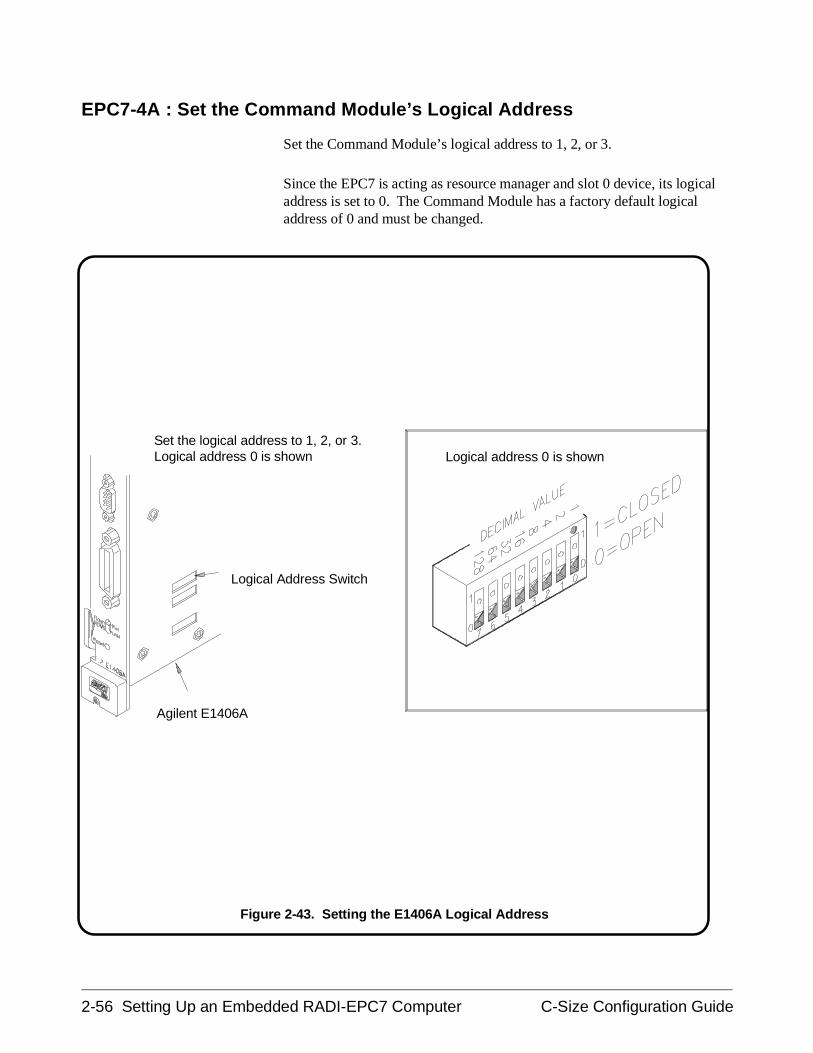
EPC7-4A : Set the Command Module’s Logical Address
Set the Command Module’s logical address to 1, 2, or 3.
Since the EPC7 is acting as resource manager and slot 0 device, its logicaladdress is set to 0. The Command Module has a factory default logicaladdress of 0 and must be changed.
Logical Address Switch
Agilent E1406A
Logical address 0 is shownSet the logical address to 1, 2, or 3.Logical address 0 is shown
Figure 2-43. Setting the E1406A Logical Address
2-56 Setting Up an Embedded RADI-EPC7 Computer C-Size Configuration Guide
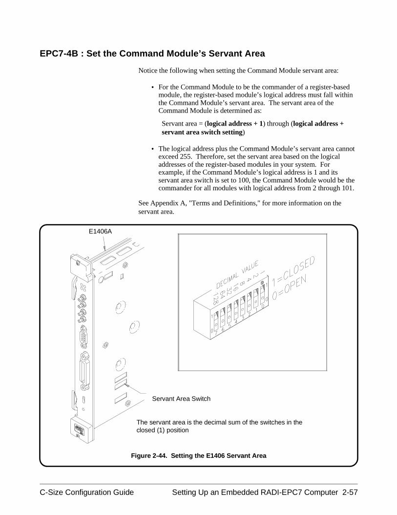
EPC7-4B : Set the Command Module’s Servant Area
Notice the following when setting the Command Module servant area:
• For the Command Module to be the commander of a register-basedmodule, the register-based module’s logical address must fall withinthe Command Module’s servant area. The servant area of theCommand Module is determined as:
Servant area = (logical address + 1) through (logical address +servant area switch setting)
• The logical address plus the Command Module’s servant area cannotexceed 255. Therefore, set the servant area based on the logicaladdresses of the register-based modules in your system. Forexample, if the Command Module’s logical address is 1 and itsservant area switch is set to 100, the Command Module would be thecommander for all modules with logical address from 2 through 101.
See Appendix A, "Terms and Definitions," for more information on theservant area.
Servant Area Switch
E1406A
The servant area is the decimal sum of the switches in theclosed (1) position
Figure 2-44. Setting the E1406 Servant Area
C-Size Configuration Guide Setting Up an Embedded RADI-EPC7 Computer 2-57
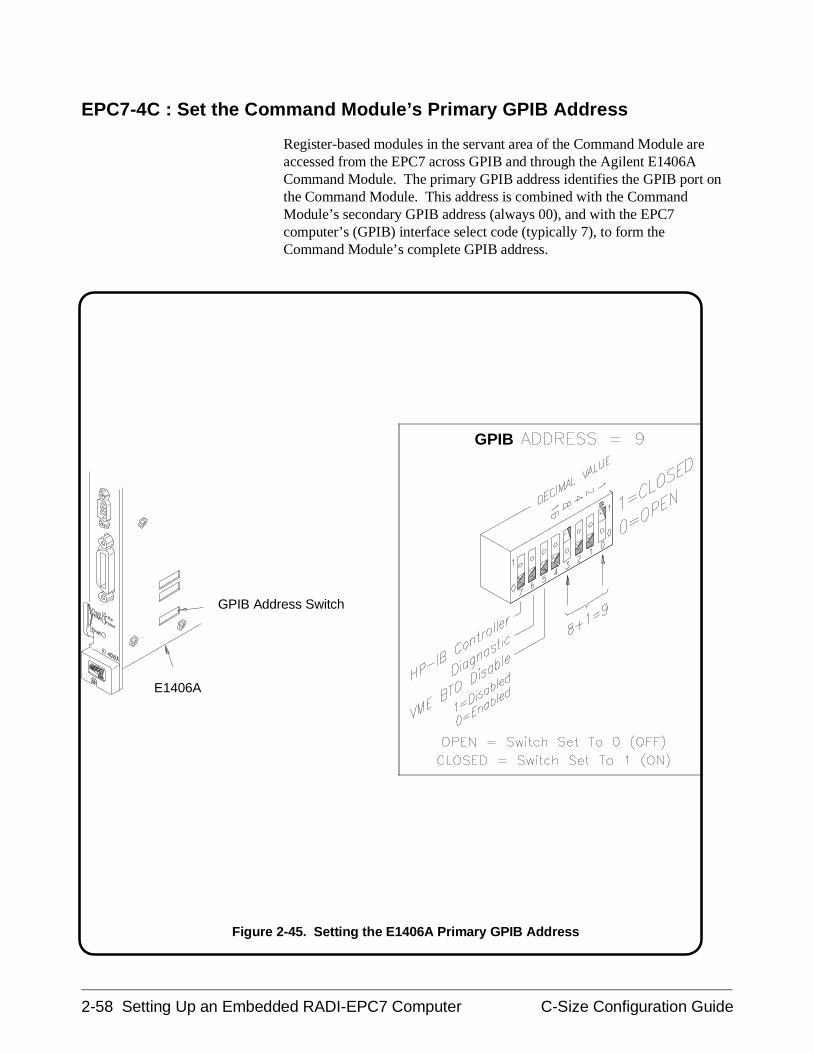
EPC7-4C : Set the Command Module’s Primary GPIB Address
Register-based modules in the servant area of the Command Module areaccessed from the EPC7 across GPIB and through the Agilent E1406ACommand Module. The primary GPIB address identifies the GPIB port onthe Command Module. This address is combined with the CommandModule’s secondary GPIB address (always 00), and with the EPC7computer’s (GPIB) interface select code (typically 7), to form theCommand Module’s complete GPIB address.
E1406A
GPIB Address Switch
GPIB
Figure 2-45. Setting the E1406A Primary GPIB Address
2-58 Setting Up an Embedded RADI-EPC7 Computer C-Size Configuration Guide
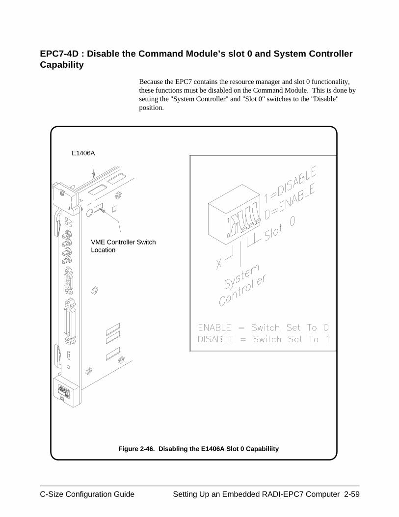
EPC7-4D : Disable the Command Module’s slot 0 and System ControllerCapability
Because the EPC7 contains the resource manager and slot 0 functionality,these functions must be disabled on the Command Module. This is done bysetting the "System Controller" and "Slot 0" switches to the "Disable"position.
VME Controller SwitchLocation
E1406A
Figure 2-46. Disabling the E1406A Slot 0 Capabiliity
C-Size Configuration Guide Setting Up an Embedded RADI-EPC7 Computer 2-59
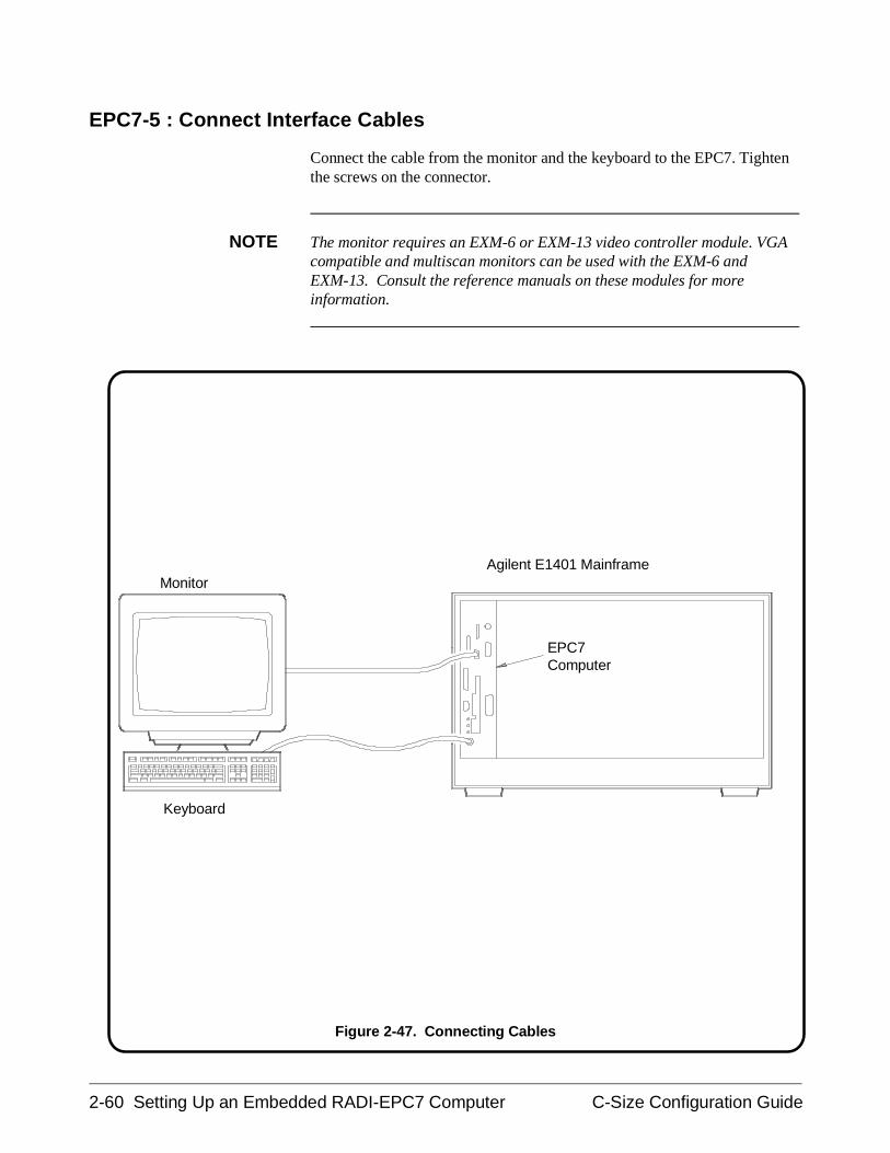
EPC7-5 : Connect Interface Cables
Connect the cable from the monitor and the keyboard to the EPC7. Tightenthe screws on the connector.
NOTE The monitor requires an EXM-6 or EXM-13 video controller module. VGAcompatible and multiscan monitors can be used with the EXM-6 andEXM-13. Consult the reference manuals on these modules for moreinformation.
EPC7Computer
Keyboard
MonitorAgilent E1401 Mainframe
Figure 2-47. Connecting Cables
2-60 Setting Up an Embedded RADI-EPC7 Computer C-Size Configuration Guide
EPC7-6 : Apply Power
When power is applied to the mainframe, the Start-Up Resource Manager(SURM) on the EPC7 will execute. An example of the configurationsequence is shown in Figure 2-48.
Use the Pg Up / Pg Dn keys to view the entire configuration. Pay particularattention to the Slot Reporting and ULA (Unique Logical Address). Theseitems will help you confirm a proper installation. Press ESC to exit theEPC7 start-up Resource Manager.
When you have a Agilent RADI-EPC7 and a Command Module in thesame system, you may want to change the commander/servant hierarchy sothat selected instruments report to the Command Module instead of theEPC7. See the "Agilent RADI-EPC7 Embedded Computer" section inProcedure 5, "Apply Power," for information on this procedure.
NOTE Refer to the EPConnect/VXI for DOS User’s Guide for more information onthe Agilent RADI-EPC7 resource manager configuration sequence and forinformation on configuration and start up errors.
C-Size Configuration Guide Setting Up an Embedded RADI-EPC7 Computer 2-61
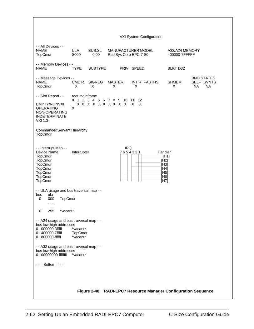
VXI System Configuration
- - All Devices - -NAME ULA BUS.SL MANUFACTURER MODEL A32/A24 MEMORYTopCmdr S000 0.00 RadiSys Corp EPC-7 S0 400000-7FFFFF
- - Memory Devices - -NAME TYPE SUBTYPE PRIV SPEED BLKT D32
- - Message Devices - - BNO STATESNAME CMD’R SIGREG MASTER INT’R FASTHS SHMEM SELF SVNTSTopCmdr X X X X X NA NA
- - Slot Report - - root mainframe0 1 2 3 4 5 6 7 8 9 10 11 12
EMPTY/NONVXI X X X X X X X X X X X X OPERATING X NON-OPERATINGINDETERMINATEVXI 1.3
Commander/Servant HierarchyTopCmdr
- - Interrupt Map - - IRQDevice Name Interrupter 7 6 5 4 3 2 1 HandlerTopCmdr [H1]TopCmdr [H2]TopCmdr [H3]TopCmdr [H4]TopCmdr [H5]TopCmdr [H6]TopCmdr [H7]
- - ULA usage and bus traversal map - -bus ula 0 000 TopCmdr
. . . . . . 0 255 *vacant*
- - A24 usage and bus traversal map - -bus low-high addresses0 000000-3fffff *vacant*0 400000-7fffff TopCmdr0 800000-ffffff *vacant*
- - A32 usage and bus traversal map - -bus low-high addresses0 00000000-ffffffff *vacant*
=== Bottom ===
Figure 2-48. RADI-EPC7 Resource Manager Configuration Sequence
2-62 Setting Up an Embedded RADI-EPC7 Computer C-Size Configuration Guide
EPC7-7 : Where To Go Next
So far you should have done the following:
• Configured the Agilent RADI-EPC7 as a Slot 0 (or Non-Slot 0 formultiple mainframes) Device
• Installed the EPC7 into the mainframe• Installed EXM expansion modules• Installed the Command Module (optional)• Connected cables• Applied power and verified installation
Once you have completed this procedure, continue with one of thefollowing procedures:
If you have multiple mainframes connected via MXIbus:
• "Procedure 3: Set Up Your System for Multiple Mainframes"
If you are using one mainframe:
• "Procedure 4: Configure and Install Instruments"
C-Size Configuration Guide Setting Up an Embedded RADI-EPC7 Computer 2-63

2-64 Setting Up an Embedded RADI-EPC7 Computer C-Size Configuration Guide
Procedure 3:Set Up the System for Multiple Mainframes
If you only have one mainframe, continue with the next procedure,Procedure 4: Configure and Install Instruments. Otherwise, if you areusing MXIbus to connect to multiple mainframes, continue with thisprocedure.
This procedure describes the recommended MXIbus configurations for2-frame and 3-frame MXIbus systems. The Agilent E1482B VXIbusExtender Module (VXI-MXI module) is shipped from the factoryconfigured for installation into slot 0. In some cases, however, you mustreconfigure the VXI-MXI module for non-slot 0 operation. This isdescribed in the following procedure. This procedure consists of thefollowing steps:
• MXIbus-1 : Set Up VXI-MXI Modules for Slot 0
• MXIbus-2 : Set Up VXI-MXI Modules for Non-Slot 0
• MXIbus-3 : Remove Terminating Networks from Middle VXI-MXIModules
• MXIbus-4 : Set the VXI-MXI Module’s Logical Address
• MXIbus-5 : Disable the VMEbus Timeout on Other Devices
• MXIbus-6 : Install VXI-MXI Modules into the Mainframe
• MXIbus-7 : Connect Interface Cables
• MXIbus-8 : Apply Power
• MXIbus-9 : What To Do Next
If you need any information on terms used in this manual, see Appendix A,"Terms and Definitions."
C-Size Configuration Guide Set Up the System for Multiple Mainframes 3-1
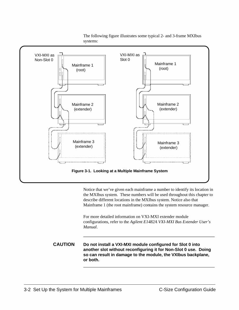
The following figure illustrates some typical 2- and 3-frame MXIbussystems:
Notice that we’ve given each mainframe a number to identify its location inthe MXIbus system. These numbers will be used throughout this chapter todescribe different locations in the MXIbus system. Notice also thatMainframe 1 (the root mainframe) contains the system resource manager.
For more detailed information on VXI-MXI extender moduleconfigurations, refer to the Agilent E1482A VXI-MXI Bus Extender User’sManual.
CAUTION Do not install a VXI-MXI module configured for Slot 0 intoanother slot without reconfiguring it for Non-Slot 0 use. Doingso can result in damage to the module, the VXIbus backplane,or both.
VXI-MXI asSlot 0
Mainframe 3 (extender)
Mainframe 2 (extender)
Mainframe 3 (extender)
Mainframe 2 (extender)
Mainframe 1 (root)
Mainframe 1 (root)
VXI-MXI asNon-Slot 0
Figure 3-1. Looking at a Multiple Mainframe System
3-2 Set Up the System for Multiple Mainframes C-Size Configuration Guide
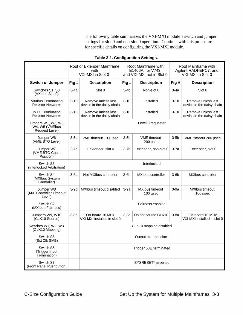
The following table summarizes the VXI-MXI module’s switch and jumpersettings for slot 0 and non-slot 0 operation. Continue with this procedurefor specific details on configuring the VXI-MXI module.
Root or Extender Mainframewith
VXI-MXI in Slot 0
Root Mainframe withE1406A, or V743
and VXI-MXI not in Slot 0
Root Mainframe withAgilent RADI-EPC7, and
VXI-MXI in Slot 0
Switch or Jumper Fig # Description Fig # Description Fig # Description
Switches S1, S8(VXIbus Slot 0)
3-4a Slot 0 3-4b Non-slot 0 3-4a Slot 0
MXIbus TerminatingResistor Networks
3-10 Remove unless lastdevice in the daisy chain
3-10 Installed 3-10 Remove unless lastdevice in the daisy chain
INTX TerminatingResistor Networks
3-10 Remove unless lastdevice in the daisy chain
3-10 Installed 3-10 Remove unless lastdevice in the daisy chain
Jumpers W1, W2, W3,W4, W5 (VMEbus
Request Level)
Level 3 requester
Jumper W6(VME BTO Level)
3-5a VME timeout 100 µsec 3-5b VME timeout 200 µsec
3-5b VME timeout 200 µsec
Jumper W7(VME BTO Chain
Position)
3-7a 1 extender, slot 0 3-7b 1 extender, non-slot 0 3-7a 1 extender, slot 0
Switch S3(Interlocked Arbitration)
Interlocked
Switch S4(MXIbus System
Controller)
3-6a Not MXIbus controller 3-6b MXIbus controller 3-6b MXIbus controller
Jumper W8(MXI Controller Timeout
Level)
3-9d MXIbus timeout disabled 3-9a MXIbus timeout 100 µsec
3-9a MXIbus timeout 100 µsec
Switch S2(MXIbus Fairness)
Fairness enabled
Jumpers W9, W10(CLK10 Source)
3-8a On-board 10 MHzVXI-MXI installed in slot 0
3-8c Do not source CLK10 3-8a On-board 10 MHzVXI-MXI installed in slot 0
Switches W1, W2, W3 (CLK10 Mapping)
CLK10 mapping disabled
Switch S6(Ext Clk SMB)
Output external clock
Switch S5(Trigger InputTermination)
Trigger 50Ω terminated
Switch S7(Front Panel Pushbutton)
SYSRESET* asserted
Table 3-1. Configuration Settings.
C-Size Configuration Guide Set Up the System for Multiple Mainframes 3-3
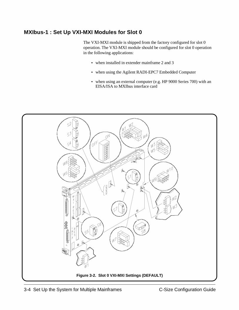
MXIbus-1 : Set Up VXI-MXI Modules for Slot 0
The VXI-MXI module is shipped from the factory configured for slot 0operation. The VXI-MXI module should be configured for slot 0 operationin the following applications:
• when installed in extender mainframe 2 and 3
• when using the Agilent RADI-EPC7 Embedded Computer
• when using an external computer (e.g. HP 9000 Series 700) with anEISA/ISA to MXIbus interface card
Figure 3-2. Slot 0 VXI-MXI Settings (DEFAULT)
3-4 Set Up the System for Multiple Mainframes C-Size Configuration Guide
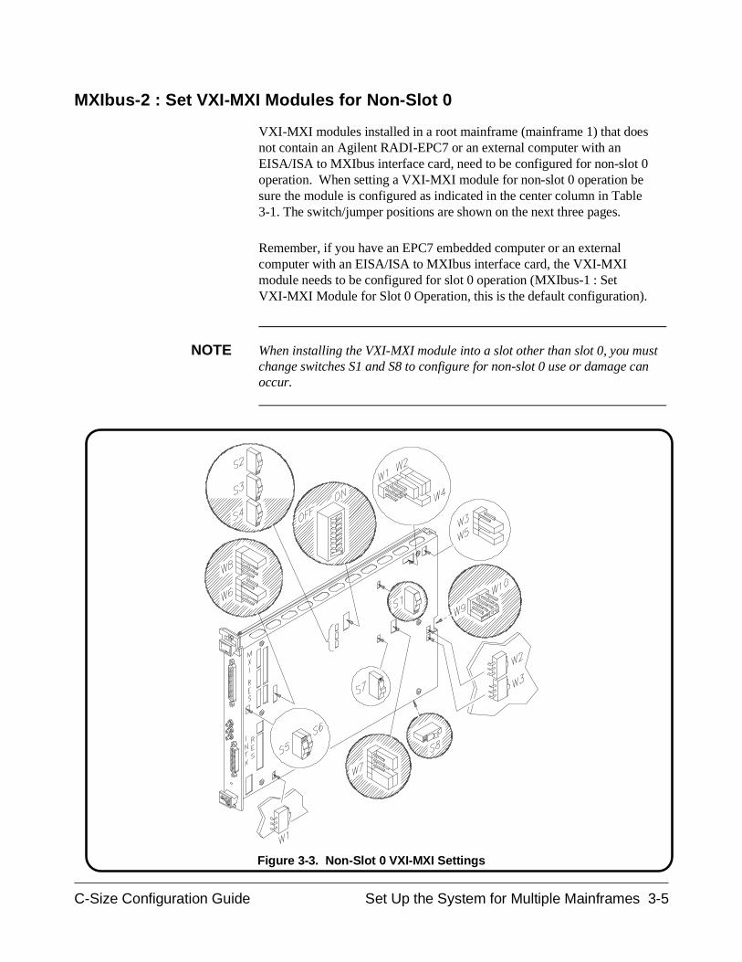
MXIbus-2 : Set VXI-MXI Modules for Non-Slot 0
VXI-MXI modules installed in a root mainframe (mainframe 1) that doesnot contain an Agilent RADI-EPC7 or an external computer with anEISA/ISA to MXIbus interface card, need to be configured for non-slot 0operation. When setting a VXI-MXI module for non-slot 0 operation besure the module is configured as indicated in the center column in Table3-1. The switch/jumper positions are shown on the next three pages.
Remember, if you have an EPC7 embedded computer or an externalcomputer with an EISA/ISA to MXIbus interface card, the VXI-MXImodule needs to be configured for slot 0 operation (MXIbus-1 : SetVXI-MXI Module for Slot 0 Operation, this is the default configuration).
NOTE When installing the VXI-MXI module into a slot other than slot 0, you mustchange switches S1 and S8 to configure for non-slot 0 use or damage canoccur.
Figure 3-3. Non-Slot 0 VXI-MXI Settings
C-Size Configuration Guide Set Up the System for Multiple Mainframes 3-5
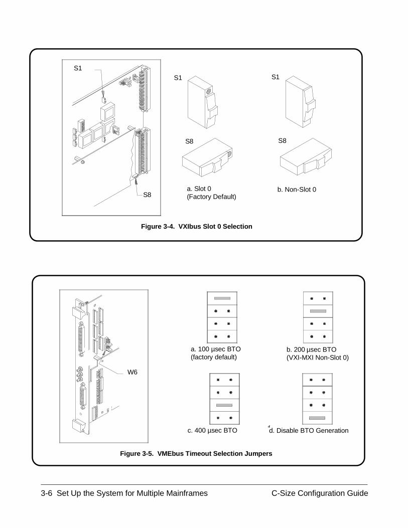
S8
S8
S1
S8
S1S1
a. Slot 0 (Factory Default)
b. Non-Slot 0
c. 400 µsec BTO d. Disable BTO Generation
W6
a. 100 µsec BTO (factory default)
b. 200 µsec BTO (VXI-MXI Non-Slot 0)
Figure 3-4. VXIbus Slot 0 Selection
Figure 3-5. VMEbus Timeout Selection Jumpers
3-6 Set Up the System for Multiple Mainframes C-Size Configuration Guide
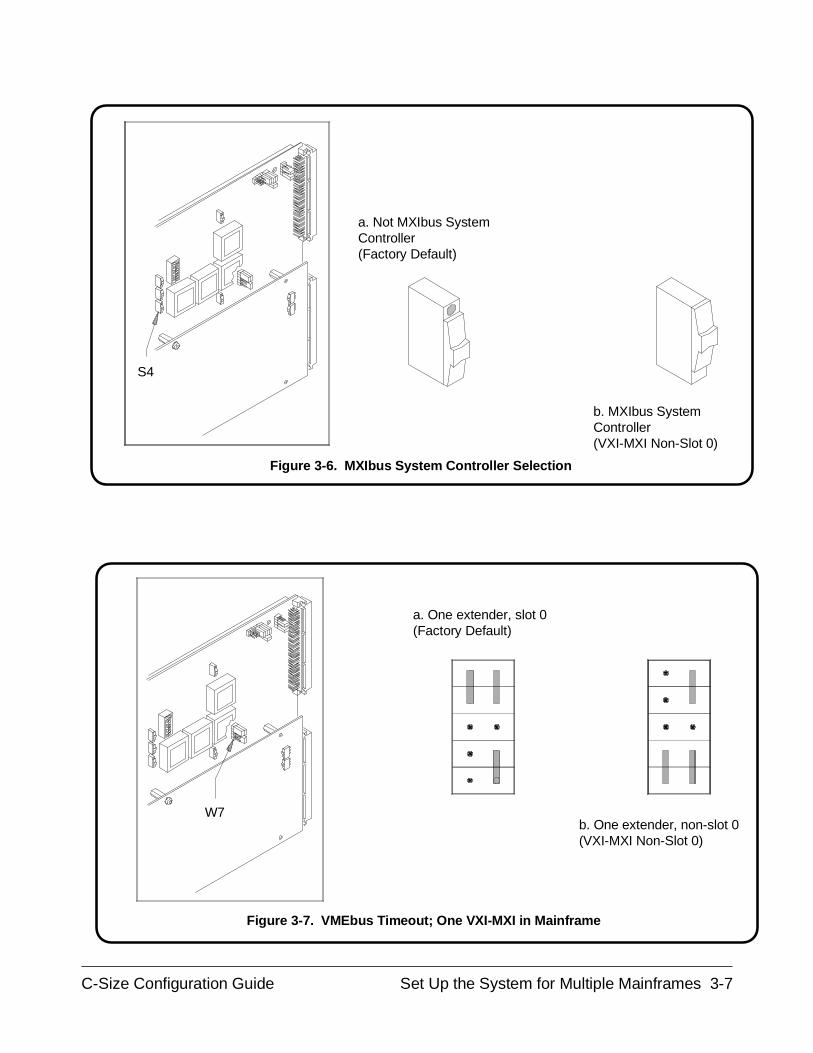
S4
a. Not MXIbus System Controller(Factory Default)
b. MXIbus System Controller(VXI-MXI Non-Slot 0)
W7
a. One extender, slot 0(Factory Default)
b. One extender, non-slot 0(VXI-MXI Non-Slot 0)
Figure 3-6. MXIbus System Controller Selection
Figure 3-7. VMEbus Timeout; One VXI-MXI in Mainframe
C-Size Configuration Guide Set Up the System for Multiple Mainframes 3-7
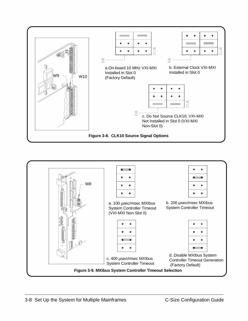
a. 100 µsec/msec MXIbusSystem Controller Timeout(VXI-MXI Non-Slot 0)
W8
d. Disable MXIbus SystemController Timeout Generation (Factory Default)
c. 400 µsec/msec MXIbusSystem Controller Timeout
b. 200 µsec/msec MXIbusSystem Controller Timeout
b. External Clock VXI-MXIInstalled in Slot 0
a.On-board 10 MHz VXI-MXIInstalled in Slot 0 (Factory Default)W9 W10
c. Do Not Source CLK10; VXI-MXINot Installed in Slot 0 (VXI-MXINon-Slot 0)
Figure 3-8. CLK10 Source Signal Options
Figure 3-9. MXIbus System Controller Timeout Selection
3-8 Set Up the System for Multiple Mainframes C-Size Configuration Guide
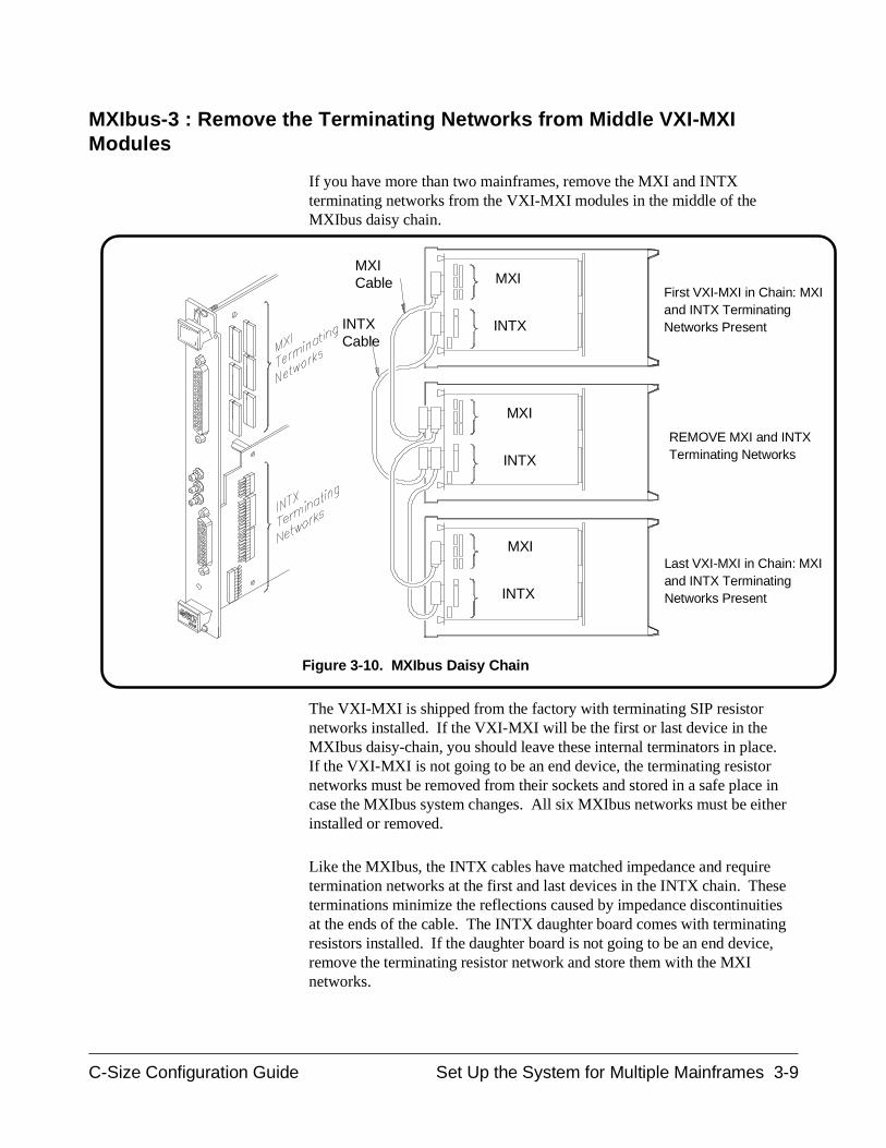
MXIbus-3 : Remove the Terminating Networks from Middle VXI-MXIModules
If you have more than two mainframes, remove the MXI and INTXterminating networks from the VXI-MXI modules in the middle of theMXIbus daisy chain.
The VXI-MXI is shipped from the factory with terminating SIP resistornetworks installed. If the VXI-MXI will be the first or last device in theMXIbus daisy-chain, you should leave these internal terminators in place.If the VXI-MXI is not going to be an end device, the terminating resistornetworks must be removed from their sockets and stored in a safe place incase the MXIbus system changes. All six MXIbus networks must be eitherinstalled or removed.
Like the MXIbus, the INTX cables have matched impedance and requiretermination networks at the first and last devices in the INTX chain. Theseterminations minimize the reflections caused by impedance discontinuitiesat the ends of the cable. The INTX daughter board comes with terminatingresistors installed. If the daughter board is not going to be an end device,remove the terminating resistor network and store them with the MXInetworks.
MXICable
INTXCable
First VXI-MXI in Chain: MXIand INTX TerminatingNetworks Present
Last VXI-MXI in Chain: MXIand INTX TerminatingNetworks Present
REMOVE MXI and INTXTerminating NetworksINTX
INTX
INTX
MXI
MXI
MXI
Figure 3-10. MXIbus Daisy Chain
C-Size Configuration Guide Set Up the System for Multiple Mainframes 3-9
MXIbus-4 : Set the VXI-MXI Module’s Logical Address
Set the logical address on your VXI-MXI modules by using the followingsteps:
1. Locate the logical address switch, an 8-bit DIP switch at U64. SeeFigure 3-11.
2. Determine your system configuration from the following figures:
– 2-Frame System - Command Module (Figure 3-12)
– 3-Frame System - Command Module (Figure 3-13)
– 2-Frame - VXI-MXI (Figure 3-14)
– 3-Frame - VXI-MXI (Figure 3-15)
– 2-Frame - RadiSys EPC-7 (Figure 3-16)
– 3-Frame - RadiSys EPC-7 (Figure 3-17)
– 2-Frame - Agilent V743 (Figure 3-18)
– 3-Frame - Agilent V743 (Figure 3-19)
3. Set the VXI-MXI logical address recommended in the abovefigures. Table 3-2 shows switch positions for some of the mostcommonly used VXI-MXI logical address.
NOTE Since the VXI-MXI does not have VXIbus resource manager capability, donot set the logical address for the VXI-MXI to 0.
3-10 Set Up the System for Multiple Mainframes C-Size Configuration Guide
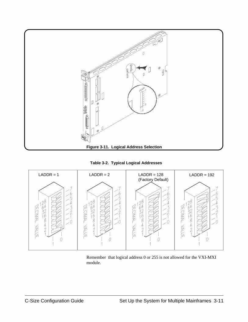
Remember that logical address 0 or 255 is not allowed for the VXI-MXImodule.
LADDR = 192LADDR = 128(Factory Default)
LADDR = 2
Figure 3-11. Logical Address Selection
LADDR = 1
Table 3-2. Typical Logical Addresses
C-Size Configuration Guide Set Up the System for Multiple Mainframes 3-11
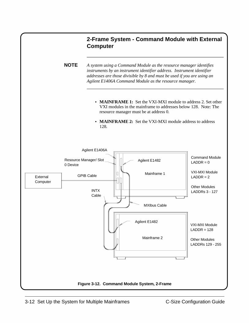
2-Frame System - Command Module with ExternalComputer
NOTE A system using a Command Module as the resource manager identifiesinstruments by an instrument identifier address. Instrument identifieraddresses are those divisible by 8 and must be used if you are using anAgilent E1406A Command Module as the resource manager.
• MAINFRAME 1: Set the VXI-MXI module to address 2. Set otherVXI modules in the mainframe to addresses below 128. Note: Theresource manager must be at address 0.
• MAINFRAME 2: Set the VXI-MXI module address to address128.
INTX Cable
Agilent E1482Resource Manager/ Slot0 Device
GPIB Cable
Agilent E1406A
ExternalComputer
MXIbus Cable
Mainframe 2
Mainframe 1
Agilent E1482VXI-MXI ModuleLADDR = 128
Other ModulesLADDRs 129 - 255
Command ModuleLADDR = 0
VXI-MXI ModuleLADDR = 2
Other ModulesLADDRs 3 - 127
Figure 3-12. Command Module System, 2-Frame
3-12 Set Up the System for Multiple Mainframes C-Size Configuration Guide
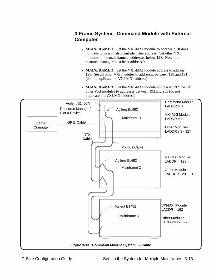
3-Frame System - Command Module with ExternalComputer
• MAINFRAME 1: Set the VXI-MXI module to address 2. It doesnot have to be an instrument identifier address. Set other VXImodules in the mainframe to addresses below 128. Note: theresource manager must be at address 0.
• MAINFRAME 2: Set the VXI-MXI module address to address128. Set all other VXI modules to addresses between 128 and 191(do not duplicate the VXI-MXI address).
• MAINFRAME 3: Set the VXI-MXI module address to 192. Set allother VXI modules to addresses between 192 and 255 (do notduplicate the VXI-MXI address).
VXI-MXI ModuleLADDR = 128
Other ModulesLADDR’s 129 - 191
Command ModuleLADDR = 0
VXI-MXI ModuleLADDR = 2
Other ModulesLADDR’s 3 - 127
ExternalComputer
Agilent E1482
INTX Cable
GPIB Cable
Agilent E1406A
Mainframe 1
Agilent E1482
Agilent E1482
VXI-MXI ModuleLADDR = 192
Other ModulesLADDR’s 193 - 255
Resource Manager/Slot 0 Device
Mainframe 3
Mainframe 2
MXIbus Cable
Figure 3-13. Command Module System, 3-Frame
C-Size Configuration Guide Set Up the System for Multiple Mainframes 3-13
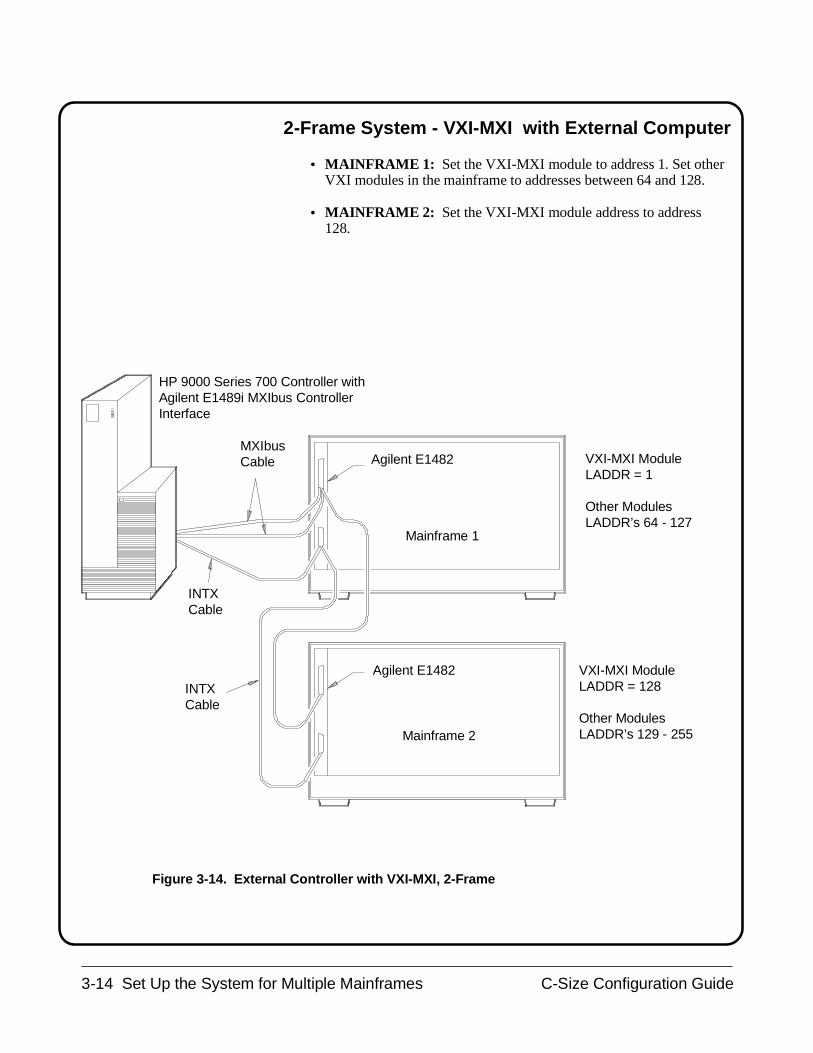
2-Frame System - VXI-MXI with External Computer
• MAINFRAME 1: Set the VXI-MXI module to address 1. Set otherVXI modules in the mainframe to addresses between 64 and 128.
• MAINFRAME 2: Set the VXI-MXI module address to address128.
VXI-MXI ModuleLADDR = 128
Other ModulesLADDR’s 129 - 255
VXI-MXI ModuleLADDR = 1
Other ModulesLADDR’s 64 - 127
Agilent E1482
Agilent E1482
Mainframe 1
Mainframe 2
HP 9000 Series 700 Controller withAgilent E1489i MXIbus ControllerInterface
MXIbusCable
INTXCable
INTXCable
Figure 3-14. External Controller with VXI-MXI, 2-Frame
3-14 Set Up the System for Multiple Mainframes C-Size Configuration Guide
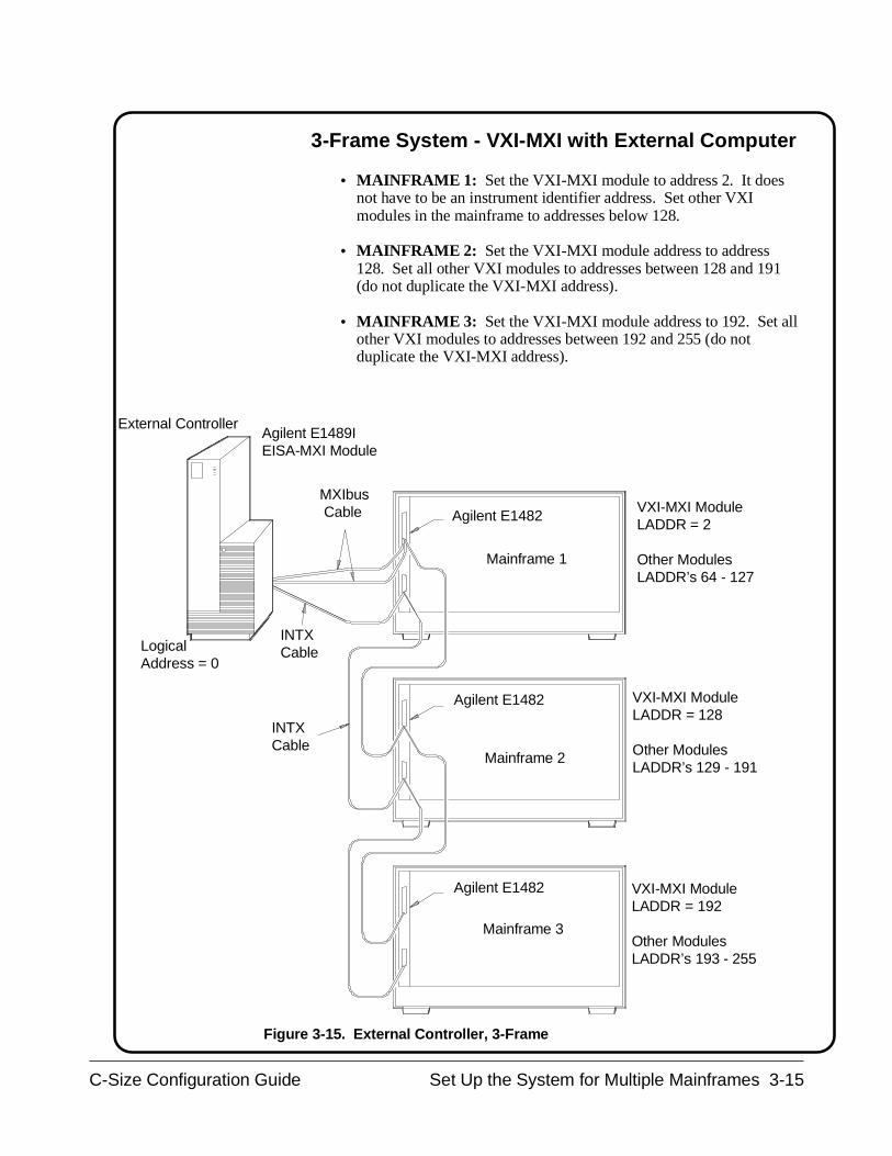
3-Frame System - VXI-MXI with External Computer
• MAINFRAME 1: Set the VXI-MXI module to address 2. It doesnot have to be an instrument identifier address. Set other VXImodules in the mainframe to addresses below 128.
• MAINFRAME 2: Set the VXI-MXI module address to address128. Set all other VXI modules to addresses between 128 and 191(do not duplicate the VXI-MXI address).
• MAINFRAME 3: Set the VXI-MXI module address to 192. Set allother VXI modules to addresses between 192 and 255 (do notduplicate the VXI-MXI address).
VXI-MXI ModuleLADDR = 128
Other ModulesLADDR’s 129 - 191
VXI-MXI ModuleLADDR = 2
Other ModulesLADDR’s 64 - 127
External Controller
Agilent E1482
INTX Cable
Mainframe 1
Agilent E1482
Agilent E1482
VXI-MXI ModuleLADDR = 192
Other ModulesLADDR’s 193 - 255
Agilent E1489IEISA-MXI Module
Mainframe 3
Mainframe 2
MXIbus Cable
INTX CableLogical
Address = 0
Figure 3-15. External Controller, 3-Frame
C-Size Configuration Guide Set Up the System for Multiple Mainframes 3-15
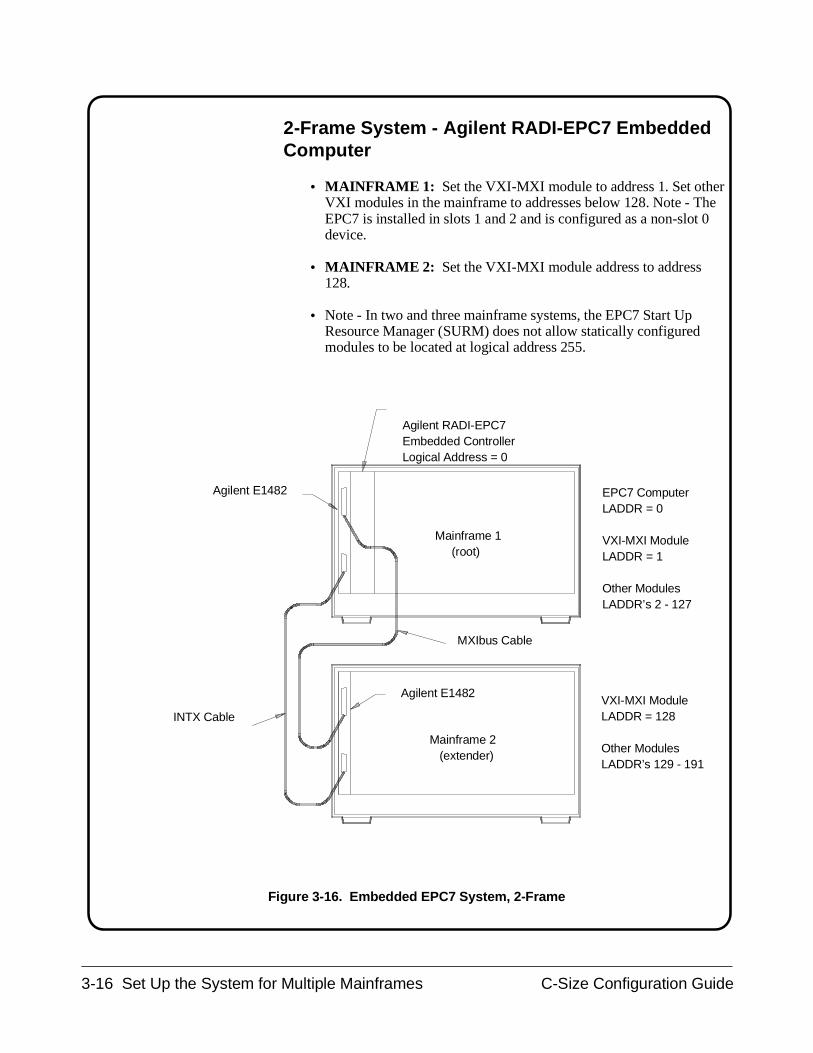
2-Frame System - Agilent RADI-EPC7 EmbeddedComputer
• MAINFRAME 1: Set the VXI-MXI module to address 1. Set otherVXI modules in the mainframe to addresses below 128. Note - TheEPC7 is installed in slots 1 and 2 and is configured as a non-slot 0device.
• MAINFRAME 2: Set the VXI-MXI module address to address128.
• Note - In two and three mainframe systems, the EPC7 Start UpResource Manager (SURM) does not allow statically configuredmodules to be located at logical address 255.
VXI-MXI ModuleLADDR = 128
Other ModulesLADDR’s 129 - 191
EPC7 ComputerLADDR = 0
VXI-MXI ModuleLADDR = 1
Other ModulesLADDR’s 2 - 127
Agilent E1482
Agilent E1482
Mainframe 1 (root)
Mainframe 2 (extender)
Agilent RADI-EPC7Embedded ControllerLogical Address = 0
MXIbus Cable
INTX Cable
Figure 3-16. Embedded EPC7 System, 2-Frame
3-16 Set Up the System for Multiple Mainframes C-Size Configuration Guide
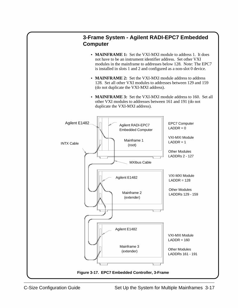
3-Frame System - Agilent RADI-EPC7 EmbeddedComputer
• MAINFRAME 1: Set the VXI-MXI module to address 1. It doesnot have to be an instrument identifier address. Set other VXImodules in the mainframe to addresses below 128. Note: The EPC7is installed in slots 1 and 2 and configured as a non-slot 0 device.
• MAINFRAME 2: Set the VXI-MXI module address to address128. Set all other VXI modules to addresses between 129 and 159(do not duplicate the VXI-MXI address).
• MAINFRAME 3: Set the VXI-MXI module address to 160. Set allother VXI modules to addresses between 161 and 191 (do notduplicate the VXI-MXI address).
VXI-MXI ModuleLADDR = 128
Other ModulesLADDRs 129 - 159
EPC7 ComputerLADDR = 0
VXI-MXI ModuleLADDR = 1
Other ModulesLADDRs 2 - 127
Agilent E1482
Agilent E1482
Mainframe 1 (root)
Mainframe 3 (extender)
Agilent RADI-EPC7Embedded Computer
MXIbus Cable
INTX Cable
VXI-MXI ModuleLADDR = 160
Other ModulesLADDRs 161 - 191
Agilent E1482
Mainframe 2 (extender)
Figure 3-17. EPC7 Embedded Controller, 3-Frame
C-Size Configuration Guide Set Up the System for Multiple Mainframes 3-17
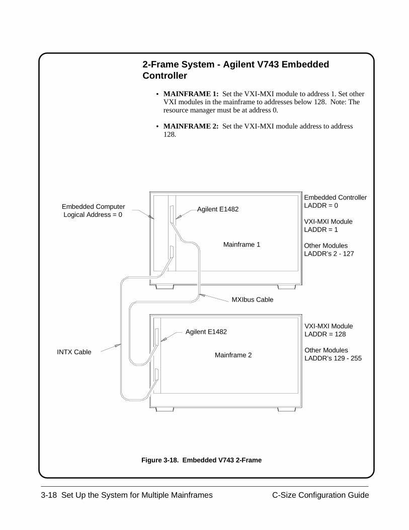
2-Frame System - Agilent V743 EmbeddedController
• MAINFRAME 1: Set the VXI-MXI module to address 1. Set otherVXI modules in the mainframe to addresses below 128. Note: Theresource manager must be at address 0.
• MAINFRAME 2: Set the VXI-MXI module address to address128.
VXI-MXI ModuleLADDR = 128
Other ModulesLADDR’s 129 - 255
Embedded ControllerLADDR = 0
VXI-MXI ModuleLADDR = 1
Other ModulesLADDR’s 2 - 127
Agilent E1482
Agilent E1482
Mainframe 1
Mainframe 2
Embedded Computer Logical Address = 0
MXIbus Cable
INTX Cable
Figure 3-18. Embedded V743 2-Frame
3-18 Set Up the System for Multiple Mainframes C-Size Configuration Guide
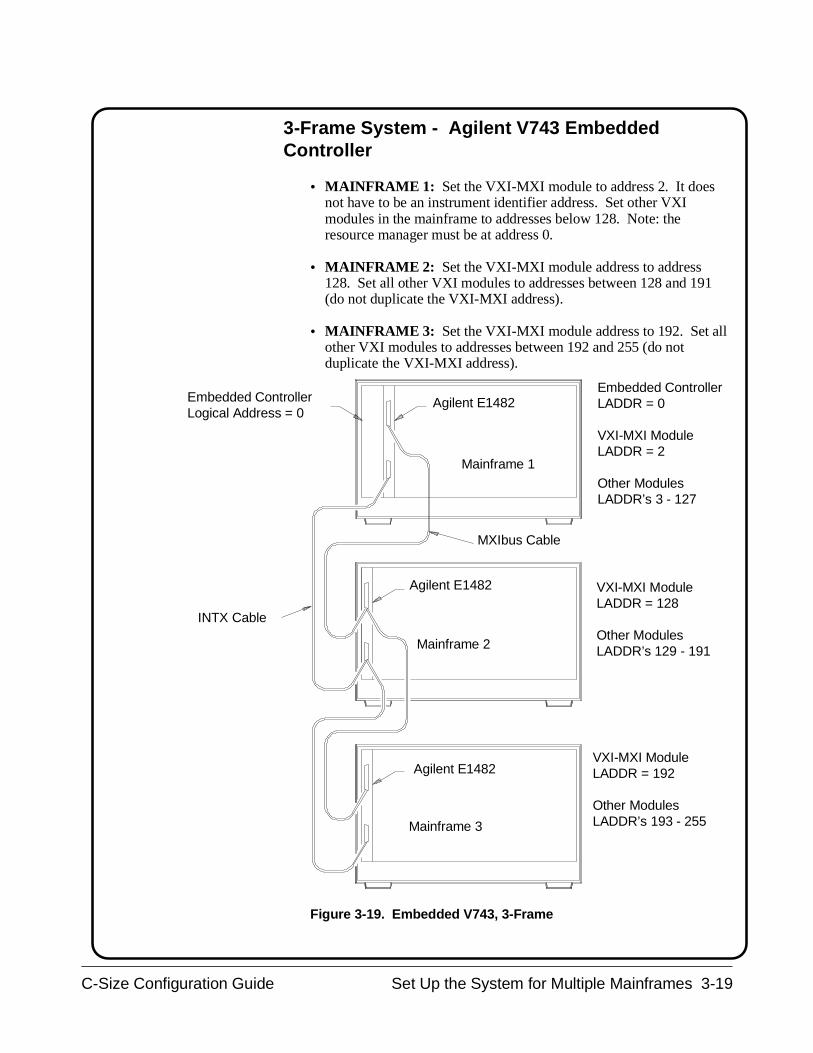
3-Frame System - Agilent V743 EmbeddedController
• MAINFRAME 1: Set the VXI-MXI module to address 2. It doesnot have to be an instrument identifier address. Set other VXImodules in the mainframe to addresses below 128. Note: theresource manager must be at address 0.
• MAINFRAME 2: Set the VXI-MXI module address to address128. Set all other VXI modules to addresses between 128 and 191(do not duplicate the VXI-MXI address).
• MAINFRAME 3: Set the VXI-MXI module address to 192. Set allother VXI modules to addresses between 192 and 255 (do notduplicate the VXI-MXI address).
VXI-MXI ModuleLADDR = 128
Other ModulesLADDR’s 129 - 191
Embedded ControllerLADDR = 0
VXI-MXI ModuleLADDR = 2
Other ModulesLADDR’s 3 - 127
Agilent E1482
Agilent E1482
Mainframe 1
Mainframe 3
Embedded ControllerLogical Address = 0
MXIbus Cable
INTX Cable
VXI-MXI ModuleLADDR = 192
Other ModulesLADDR’s 193 - 255
Agilent E1482
Mainframe 2
Figure 3-19. Embedded V743, 3-Frame
C-Size Configuration Guide Set Up the System for Multiple Mainframes 3-19
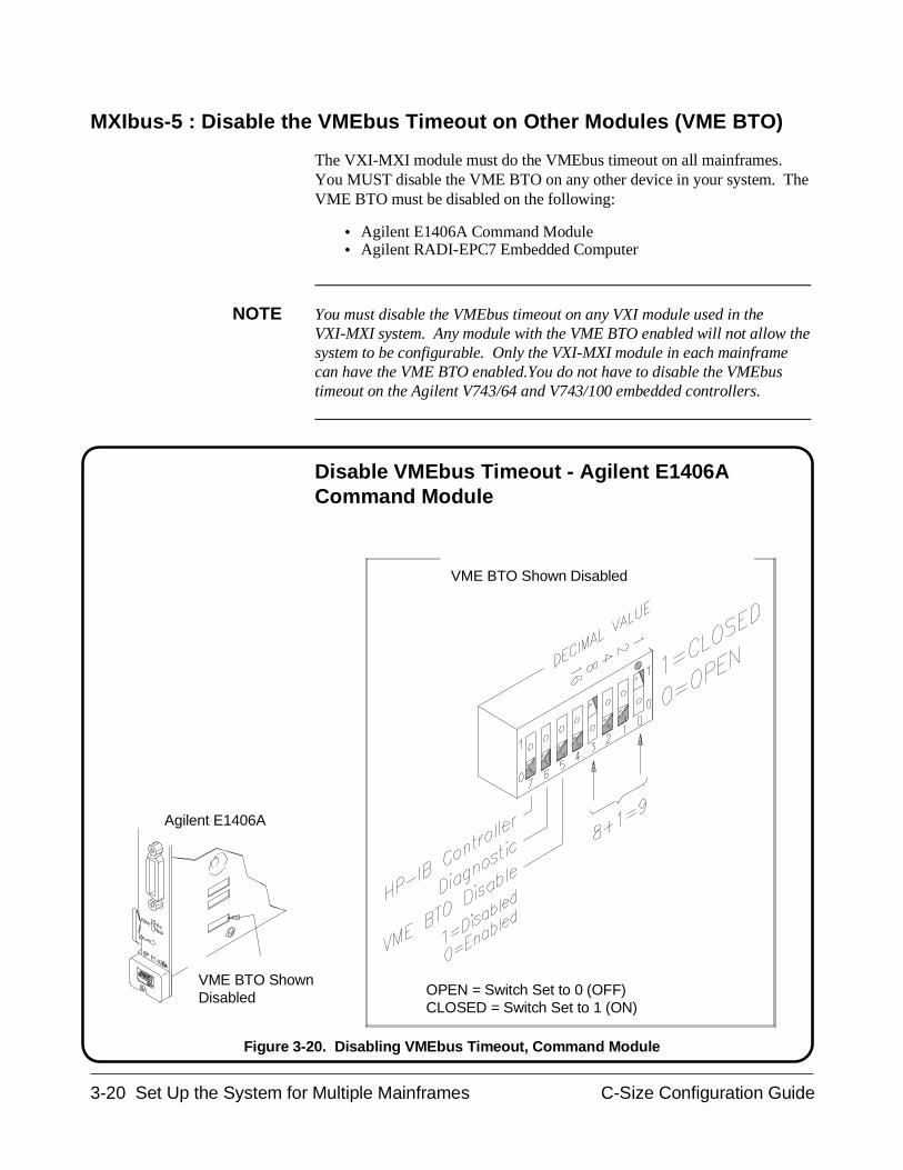
MXIbus-5 : Disable the VMEbus Timeout on Other Modules (VME BTO)
The VXI-MXI module must do the VMEbus timeout on all mainframes.You MUST disable the VME BTO on any other device in your system. TheVME BTO must be disabled on the following:
• Agilent E1406A Command Module• Agilent RADI-EPC7 Embedded Computer
NOTE You must disable the VMEbus timeout on any VXI module used in theVXI-MXI system. Any module with the VME BTO enabled will not allow thesystem to be configurable. Only the VXI-MXI module in each mainframecan have the VME BTO enabled.You do not have to disable the VMEbustimeout on the Agilent V743/64 and V743/100 embedded controllers.
Disable VMEbus Timeout - Agilent E1406ACommand Module
Agilent E1406A
VME BTO ShownDisabled
VME BTO Shown Disabled
OPEN = Switch Set to 0 (OFF)CLOSED = Switch Set to 1 (ON)
Figure 3-20. Disabling VMEbus Timeout, Command Module
3-20 Set Up the System for Multiple Mainframes C-Size Configuration Guide
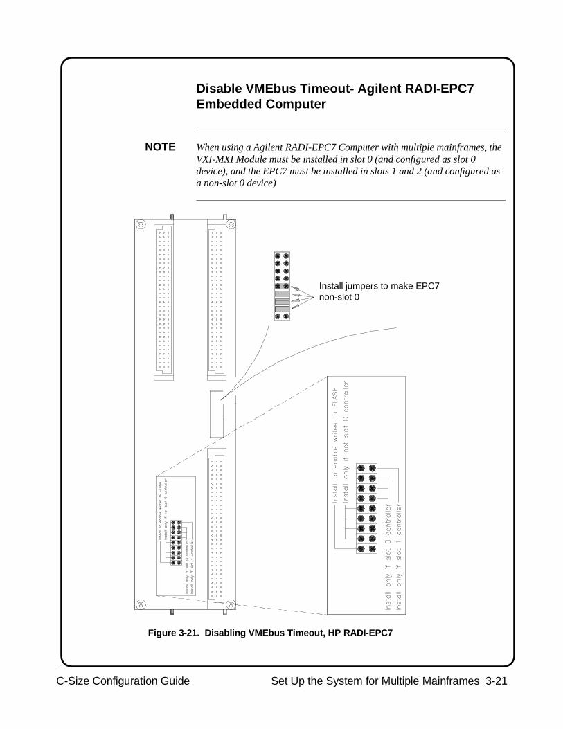
Disable VMEbus Timeout- Agilent RADI-EPC7Embedded Computer
NOTE When using a Agilent RADI-EPC7 Computer with multiple mainframes, theVXI-MXI Module must be installed in slot 0 (and configured as slot 0device), and the EPC7 must be installed in slots 1 and 2 (and configured asa non-slot 0 device)
Install jumpers to make EPC7non-slot 0
Figure 3-21. Disabling VMEbus Timeout, HP RADI-EPC7
C-Size Configuration Guide Set Up the System for Multiple Mainframes 3-21

MXIbus-6 : Install VXI-MXI Modules into Mainframes
Use the following steps to install the VXI-MXI Modules into themainframes. Install VXI-MXI modules in mainframes 2 and 3 into slot 0 ofthe mainframe. Install VXI-MXI module in mainframe 1 into the slot nextto the slot 0 device unless the VXI-MXI module needs to be the slot 0device (when EPC7 or EISA/ISA to MXIbus is used). See Figure 3-23 onthe next page.
NOTE If you have an EPC7 embedded computer or an external computer with anEISA/ISA to MXIbus interface card, the VXI-MXI module in mainframe 1needs to be installed in slot 0 (and configured as a slot 0 device).
1. Turn off mainframe power by pressing the button in the bottom leftcorner of the mainframe.
2. If the modules will be installed into a D-Size mainframe, install asupport designed for installing C-Size cards in D-Size mainframes.
3. Insert the module into the mainframe by aligning the top andbottom of the card with the card guides inside the mainframe.Slowly push the module straight into the slot until it seats in thebackplane receptacles. The front panel of the module should beeven with the front panel of the mainframe.
4. Tighten the retaining screws on the top and bottom edges of thefront panel.
3-22 Set Up the System for Multiple Mainframes C-Size Configuration Guide
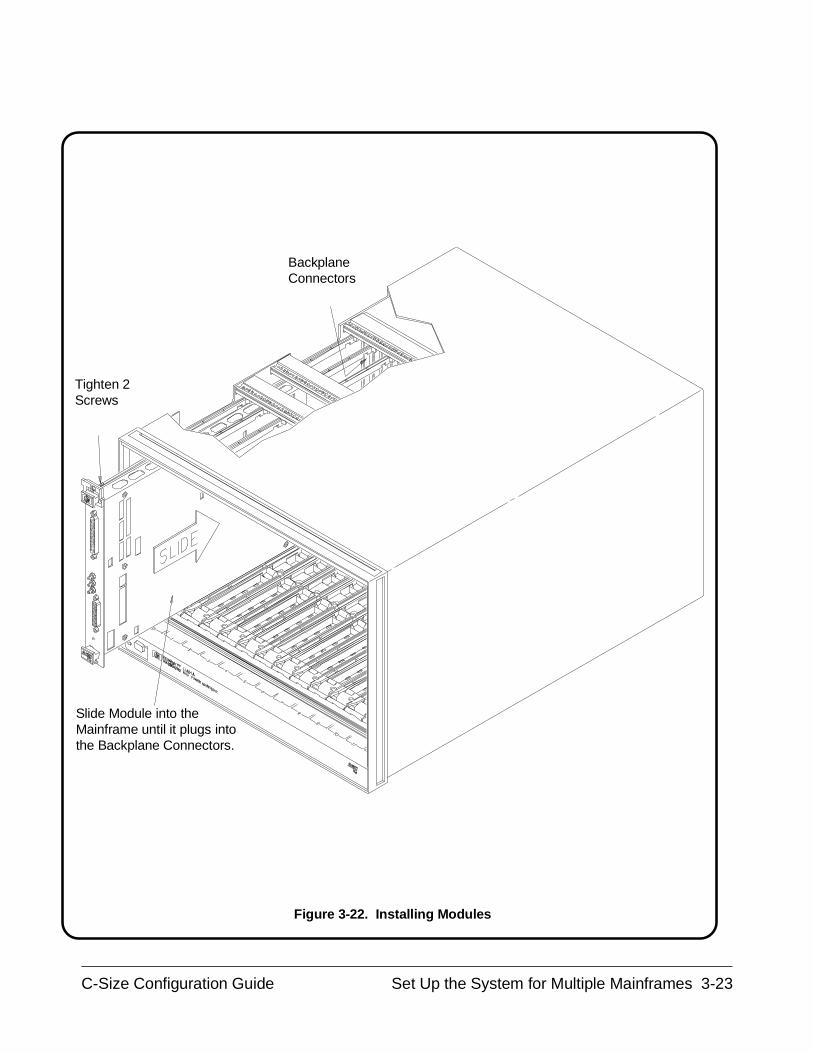
BackplaneConnectors
Tighten 2Screws
Slide Module into theMainframe until it plugs intothe Backplane Connectors.
Figure 3-22. Installing Modules
C-Size Configuration Guide Set Up the System for Multiple Mainframes 3-23
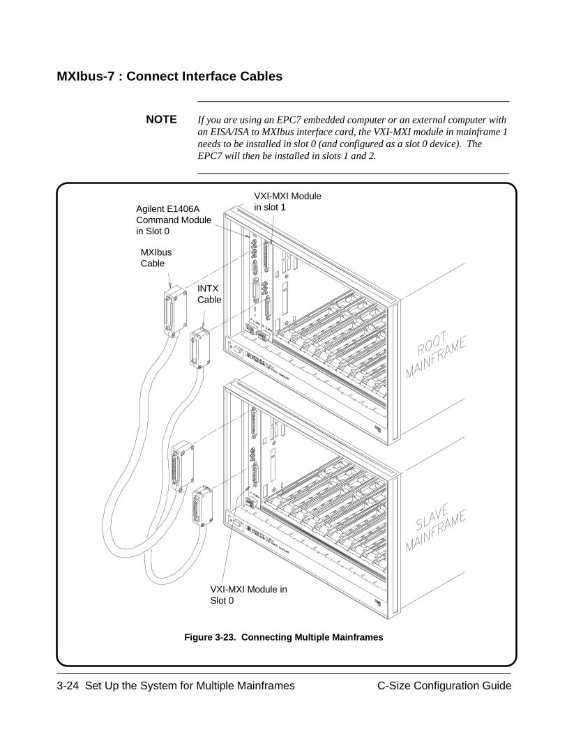
MXIbus-7 : Connect Interface Cables
NOTE If you are using an EPC7 embedded computer or an external computer withan EISA/ISA to MXIbus interface card, the VXI-MXI module in mainframe 1needs to be installed in slot 0 (and configured as a slot 0 device). TheEPC7 will then be installed in slots 1 and 2.
MXIbus Cable
INTXCable
VXI-MXI Module inSlot 0
Agilent E1406A Command Modulein Slot 0
VXI-MXI Module in slot 1
Figure 3-23. Connecting Multiple Mainframes
3-24 Set Up the System for Multiple Mainframes C-Size Configuration Guide

MXIbus-8 : Apply Power
Once you have installed your MXIbus system, you can apply power bypressing the button in the lower left corner of the mainframe. There areseveral ways you can confirm installation. However, the method useddepends on what type of system controller you are using.
Turn the mainframe’s power on and check the system configuration withthe examples shown in Procedure 5 : Apply Power later in this guide.Confirm installation by checking the card address and slot location.
MXIbus-9 : Where To Go Next
So far you should have done the following:
• Set up the VXI-MXI modules for slot 0 and non-slot 0 operation• Removed terminating networks from the middle VXI-MXI modules • Set the VXI-MXI module logical address• Disable VMEbus Timeout on other devices• Installed the VXI-MXI Modules• Connected Interface Cables• Applied Power and confirmed installation
Once you have completed these steps, continue with the followingprocedure:
• "Procedure 4: Configure and Install Instruments"
C-Size Configuration Guide Set Up the System for Multiple Mainframes 3-25

3-26 Set Up the System for Multiple Mainframes C-Size Configuration Guide
Procedure 4:Configure and Install Instruments
This procedure describes how to configure and install VXI modules intoyour Agilent 75000 Series C VXIbus System. The procedure consists of thefollowing steps:
• Step-1 : Download Instrument Drivers
• Step-2 : Set Instrument Logical Addresses
• Step-3 : Install A- and B-Size Modules With a Module Carrier
• Step-4 : Install C-Size Modules
• Step-5 : Install a Chassis Shield
• Step-6 : Install Backplane Connector Shields
• Step-7 : Install Faceplate Panels
• Step-8 : Where To Go Next
WARNING SHOCK HAZARD. Only service-trained personnel who are awareof the hazards involved should install, remove, or configure thesystem. Before you perform any procedures in this guide,disconnect AC power and field wiring from the mainframe.
To avoid electrical shock, always cover unused slots with thefaceplate panels that came with the mainframe.
CAUTION STATIC ELECTRICITY. Static electricity is a major cause ofcomponent failure. To prevent damage to the electricalcomponents in the mainframe and plug-in modules, observeanti-static techniques whenever handling a module.
C-Size Configuration Guide Configure and Install Instruments 4-1
CAUTION It is your responsibility to ensure adequate cooling is suppliedto all modules installed in the mainframe. Section B.7.2.4 of theVXIbus Specification (Revision 1.3) discusses module coolingrequirements. Section B.7.3.5 discusses mainframe coolingrequirements.
NOTE When installing VME devices in the Agilent 75000 Series C mainframe, thedevices must not be in conflict with the A24/A32 addresses allocated by theCommand Module when functioning as the resource manager. Refer to theAgilent E1406 user’s manual for information on A24/A32 address mapping.
4-2 Configure and Install Instruments C-Size Configuration Guide
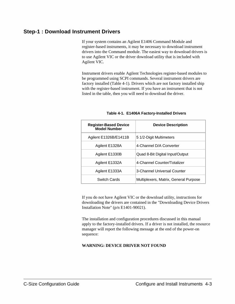
Step-1 : Download Instrument Drivers
If your system contains an Agilent E1406 Command Module andregister-based instruments, it may be necessary to download instrumentdrivers into the Command module. The easiest way to download drivers isto use Agilent VIC or the driver download utility that is included withAgilent VIC.
Instrument drivers enable Agilent Technologies register-based modules tobe programmed using SCPI commands. Several instrument drivers arefactory installed (Table 4-1). Drivers which are not factory installed shipwith the register-based instrument. If you have an instrument that is notlisted in the table, then you will need to download the driver.
If you do not have Agilent VIC or the download utility, instructions fordownloading the drivers are contained in the "Downloading Device DriversInstallation Note" (p/n E1401-90021).
The installation and configuration procedures discussed in this manualapply to the factory-installed drivers. If a driver is not installed, the resourcemanager will report the following message at the end of the power-onsequence:
WARNING: DEVICE DRIVER NOT FOUND
Register-Based DeviceModel Number
Device Description
Agilent E1326B/E1411B 5 1/2-Digit Multimeters
Agilent E1328A 4-Channel D/A Converter
Agilent E1330B Quad 8-Bit Digital Input/Output
Agilent E1332A 4-Channel Counter/Totalizer
Agilent E1333A 3-Channel Universal Counter
Switch Cards Multiplexers, Matrix, General Purpose
Table 4-1. E1406A Factory-Installed Drivers
C-Size Configuration Guide Configure and Install Instruments 4-3
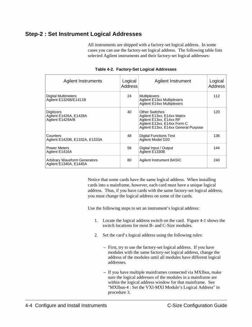
Step-2 : Set Instrument Logical Addresses
All instruments are shipped with a factory-set logical address. In somecases you can use the factory-set logical address. The following table listsselected Agilent instruments and their factory-set logical addresses:
Notice that some cards have the same logical address. When installingcards into a mainframe, however, each card must have a unique logicaladdress. Thus, if you have cards with the same factory-set logical address,you must change the logical address on some of the cards.
Use the following steps to set an instrument’s logical address:
1. Locate the logical address switch on the card. Figure 4-1 shows theswitch locations for most B- and C-Size modules.
2. Set the card’s logical address using the following rules:
– First, try to use the factory-set logical address. If you havemodules with the same factory-set logical address, change theaddress of the modules until all modules have different logicaladdresses.
– If you have multiple mainframes connected via MXIbus, makesure the logical addresses of the modules in a mainframe arewithin the logical address window for that mainframe. See"MXIbus-4 : Set the VXI-MXI Module’s Logical Address" inprocedure 3.
Agilent Instruments LogicalAddress
Agilent Instrument LogicalAddress
Digital MultimetersAgilent E1326B/E1411B
24 MultiplexersAgilent E13xx MultiplexersAgilent E14xx Multiplexers
112
DigitizersAgilent E1426A, E1428AAgilent E1429A/B
40 Other SwitchesAgilent E13xx, E14xx MatrixAgilent E13xx, E14xx RFAgilent E13xx, E14xx Form CAgilent E13xx, E14xx General Purpose
120
CountersAgilent E1420B, E1332A, E1333A
48 Digital Functions TestAgilent Model D20
136
Power MetersAgilent E1416A
56 Digital Input / OutputAgilent E1330B
144
Arbitrary Waveform GeneratorsAgilent E1340A, E1445A
80 Agilent Instrument BASIC 240
Table 4-2. Factory-Set Logical Addresses
4-4 Configure and Install Instruments C-Size Configuration Guide
– Valid logical addresses are 1 through 255. Most Agilentmodules are statically configured modules, which means thatyou have to physically set the address on the switch. Todynamically configure a module which supports dynamicconfiguration, its logical address must be set to 255. Adynamically configured module’s address is setprogrammatically by the resource manager. Note, however, if astatically configured module is set to 255, the resource managerwill not dynamically configure any module.
For Agilent E1406Command Module
Only
– Each instrument must have one plug-in module assigned as anInstrument Identifier. The Instrument Identifier is the modulewith its logical address set to a multiple of 8, such as 8, 16, or 24.
– An instrument consisting of multiple modules is called a virtualinstrument. The modules of the virtual instrument must beassigned successive logical addresses beginning with the addressof the Instrument Identifier. For example, to create a scanningmultimeter virtual instrument which consists of a multimeter andtwo multiplexers, the logical addresses could be set to:
24 (multimeter)25 (1st multiplexer)26 (2nd multiplexer)
Note, however, you cannot combine multiple modules of thesame type (like multiple multimeters or multiple counters) intovirtual instruments.
– A plug-in module with a logical address that is not a multiple of8, or that is not part of a virtual instrument, is an unassignedmodule. Such modules must be programmed at the register level,rather than with SCPI commands. (A secondary GPIB addresscan be given to an unassigned module with the CommandModule’s User-Defined Commander/Servant Hierarchy table(see the Agilent E1406 User’s Manual).)
C-Size Configuration Guide Configure and Install Instruments 4-5
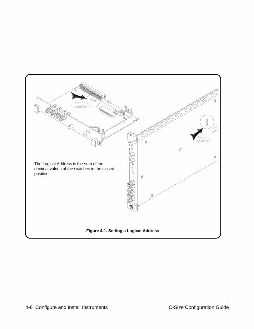
The Logical Address is the sum of thedecimal values of the switches in the closedposition
Figure 4-1. Setting a Logical Address
4-6 Configure and Install Instruments C-Size Configuration Guide
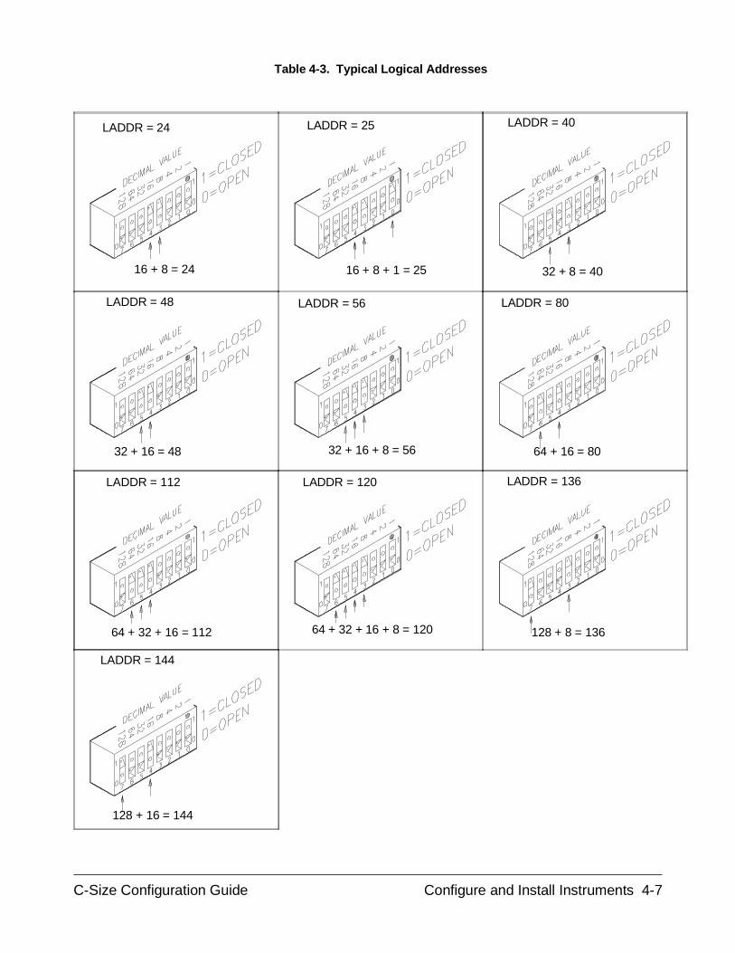
LADDR = 24
64 + 16 = 8032 + 16 + 8 = 5632 + 16 = 48
16 + 8 = 24
128 + 8 = 13664 + 32 + 16 + 8 = 12064 + 32 + 16 = 112
128 + 16 = 144
16 + 8 + 1 = 25 32 + 8 = 40
LADDR = 40LADDR = 25
LADDR = 48 LADDR = 80LADDR = 56
LADDR = 112 LADDR = 136LADDR = 120
LADDR = 144
Table 4-3. Typical Logical Addresses
C-Size Configuration Guide Configure and Install Instruments 4-7
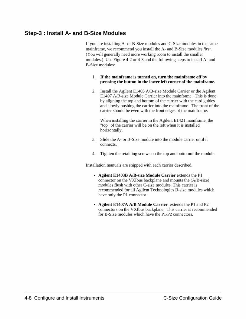
Step-3 : Install A- and B-Size Modules
If you are installing A- or B-Size modules and C-Size modules in the samemainframe, we recommend you install the A- and B-Size modules first.(You will generally need more working room to install the smallermodules.) Use Figure 4-2 or 4-3 and the following steps to install A- andB-Size modules:
1. If the mainframe is turned on, turn the mainframe off bypressing the button in the lower left corner of the mainframe.
2. Install the Agilent E1403 A/B-size Module Carrier or the AgilentE1407 A/B-size Module Carrier into the mainframe. This is doneby aligning the top and bottom of the carrier with the card guidesand slowly pushing the carrier into the mainframe. The front of thecarrier should be even with the front edges of the mainframe.
When installing the carrier in the Agilent E1421 mainframe, the"top" of the carrier will be on the left when it is installedhorizontally.
3. Slide the A- or B-Size module into the module carrier until itconnects.
4. Tighten the retaining screws on the top and bottomof the module.
Installation manuals are shipped with each carrier described.
• Agilent E1403B A/B-size Module Carrier extends the P1connector on the VXIbus backplane and mounts the (A/B-size)modules flush with other C-size modules. This carrier isrecommended for all Agilent Technologies B-size modules whichhave only the P1 connector.
• Agilent E1407A A/B Module Carrier extends the P1 and P2connectors on the VXIbus backplane. This carrier is recommendedfor B-Size modules which have the P1/P2 connectors.
4-8 Configure and Install Instruments C-Size Configuration Guide
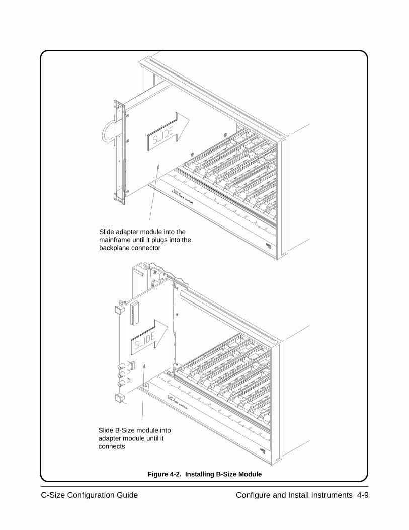
Slide adapter module into themainframe until it plugs into thebackplane connector
Slide B-Size module intoadapter module until itconnects
Figure 4-2. Installing B-Size Module
C-Size Configuration Guide Configure and Install Instruments 4-9
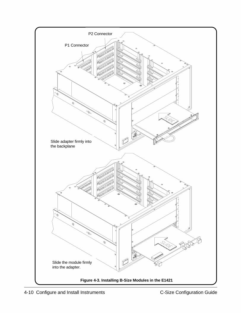
Slide the module firmlyinto the adapter.
Slide adapter firmly intothe backplane
P1 Connector
P2 Connector
Figure 4-3. Installing B-Size Modules in the E1421
4-10 Configure and Install Instruments C-Size Configuration Guide
Step-4 : Install C-Size Modules
C-Size Modules can be installed in any slot except slot 0, and need not beinstalled in adjacent slots. However, when installing multiple moduleswhich make a virtual instrument, the modules should be installed inadjacent slots. This allows cables to be easily connected between themodules. When installing a virtual instrument such as a scanningmultimeter, install the multimeter to the left of the multiplexers, which arethen installed in adjacent slots to the right.
Use Figure 4-4 or 4-5 and the the following steps to install C-Size modules:
1. If the mainframe is turned on, turn the mainframe off bypressing the button in the lower left corner of the mainframe.
2. Insert the module into the mainframe by aligning the top andbottom of the module with the card guides inside the mainframe.Slowly push the module straight into the slot until it seats in thebackplane connectors. The front panel of the module should beeven with the front edges of the mainframe.
When installing the module in the Agilent E1421 mainframe, the"top" of the module will be on the left when it is installedhorizontally.
3. Tighten the retaining screws on the top and bottom of the module.
NOTE If the module fails to insert properly, make sure you are lined up in the cardguides and make sure the tabs are turned towards the center of the card.
C-Size Configuration Guide Configure and Install Instruments 4-11

1. Slide the module into themainframe until it touches thebackplane connectors
3. Tighten2 screws
2. Seat the module into themainframe by pushing in theextraction levers
Figure 4.4. Installing C-Size Modules
4-12 Configure and Install Instruments C-Size Configuration Guide
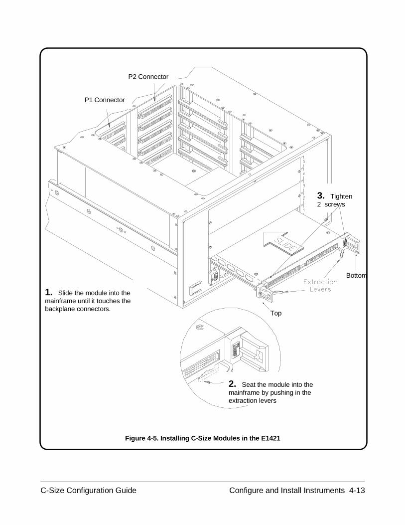
1. Slide the module into themainframe until it touches thebackplane connectors.
P1 Connector
P2 Connector
Top
Bottom
2. Seat the module into themainframe by pushing in theextraction levers
3. Tighten2 screws
Figure 4-5. Installing C-Size Modules in the E1421
C-Size Configuration Guide Configure and Install Instruments 4-13
Step-5 : Install a Chassis Shield
If EMI shielding is needed, install the Agilent E1409A/B Chassis Shieldaccording to the instructions in the Agilent E1409A/B Installation Manual.
This shield is the Agilent Technologies implementation of Section B.7.3.4of the VXIbus Specification (Revision 1.3) that allows grounded shieldingbetween mainframe slots. Typical applications for the chassis shieldinclude isolating modules that generate electro-magnetic interference (EMI)at excessive levels, and shielding modules from noise sources duringsensitive measurements.
The chassis shield assembly contains a plated-steel shield with fourconductive chassis shield guides and mounting hardware. Twoadhesive-backed thermoplastic insulators are also included and can beattached to the chassis shield if desired. Since the chassis shield fitsbetween slots in the mainframe, you do not lose the use of a slot byinstalling the shield.
4-14 Configure and Install Instruments C-Size Configuration Guide
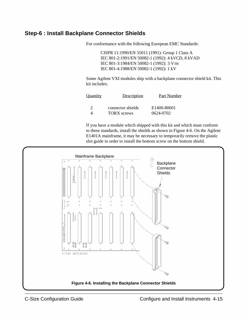
Step-6 : Install Backplane Connector Shields
For conformance with the following European EMC Standards:
CISPR 11:1990/EN 55011 (1991): Group 1 Class AIEC 801-2:1991/EN 50082-1 (1992): 4 kVCD, 8 kVADIEC 801-3:1984/EN 50082-1 (1992): 3 V/mIEC 801-4:1988/EN 50082-1 (1992): 1 kV
Some Agilent VXI modules ship with a backplane connector shield kit. Thiskit includes:
Quantity Description Part Number
2 connector shields E1400-80601 4 TORX screws 0624-0702
If you have a module which shipped with this kit and which must conformto these standards, install the shields as shown in Figure 4-6. On the AgilentE1401A mainframe, it may be necessary to temporarily remove the plasticslot guide in order to install the bottom screw on the bottom shield.
BackplaneConnectorShields
Mainframe Backplane
Figure 4-6. Installing the Backplane Connector Shields
C-Size Configuration Guide Configure and Install Instruments 4-15
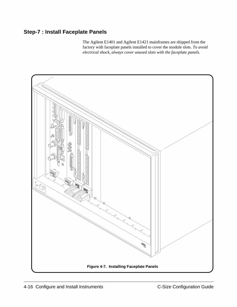
Step-7 : Install Faceplate Panels
The Agilent E1401 and Agilent E1421 mainframes are shipped from thefactory with faceplate panels installed to cover the module slots. To avoidelectrical shock, always cover unused slots with the faceplate panels.
Figure 4-7. Installing Faceplate Panels
4-16 Configure and Install Instruments C-Size Configuration Guide

Step-8 : Where To Go Next
So far you should have done the following:
• Downloaded device drivers (with Command Module Only)• Set the instrument logical addresses• Installed A-, B-, and C-size modules• Installed chassis shield (optional)• Installed faceplate panels
Once you have installed all your VXI modules, continue with the followingprocedure:
• Procedure 5 : Apply Power
C-Size Configuration Guide Configure and Install Instruments 4-17

4-18 Configure and Install Instruments C-Size Configuration Guide
Procedure 5:Apply Power
Once the controller to VXI mainframe interface has been set up andmodules have been installed, power can be applied to the system again. Thissection covers the power-on sequences of the following controller-basedVXIbus systems:
• Agilent E1406 Command Module with an External Computer
• HP 9000 Series 700 Computer
• Agilent E1497A/E1498A Embedded V743 Controller
• Agilent RADI-EPC7 Embedded 486 Computer
Power is applied by pressing the mainframe’s power switch. At power-on,the installed modules begin their self-test routines and the system resourcemanager begins its configuration sequence. If a plug-in module fails its selftest, the device is taken off-line by the system’s resource manager and isexcluded from the configuration process.
Agilent E1406Command Module
with an ExternalComputer
In a system controlled by an external computer, the Agilent E1406ACommand Module is often the system’s resource manager. An example ofthe E1406A’s power-on and configuration sequence is shown in Figure 5-1.This sequence can be monitored on an RS-232 terminal or printer connectedto the Command Module’s RS-232 serial interface port. Pressing CTRL Son the terminal keyboard pauses the sequence. Pressing CTRL Q allows thesequence to resume. Note that once the sequence is paused, it remainspaused until CTRL Q is pressed.
NOTE The Agilent E1406 Command Module’s Flash ROM switch must be set tothe ’Run’ position when the Command Module is turned on.
C-Size Configuration Guide Applying Power 5-1
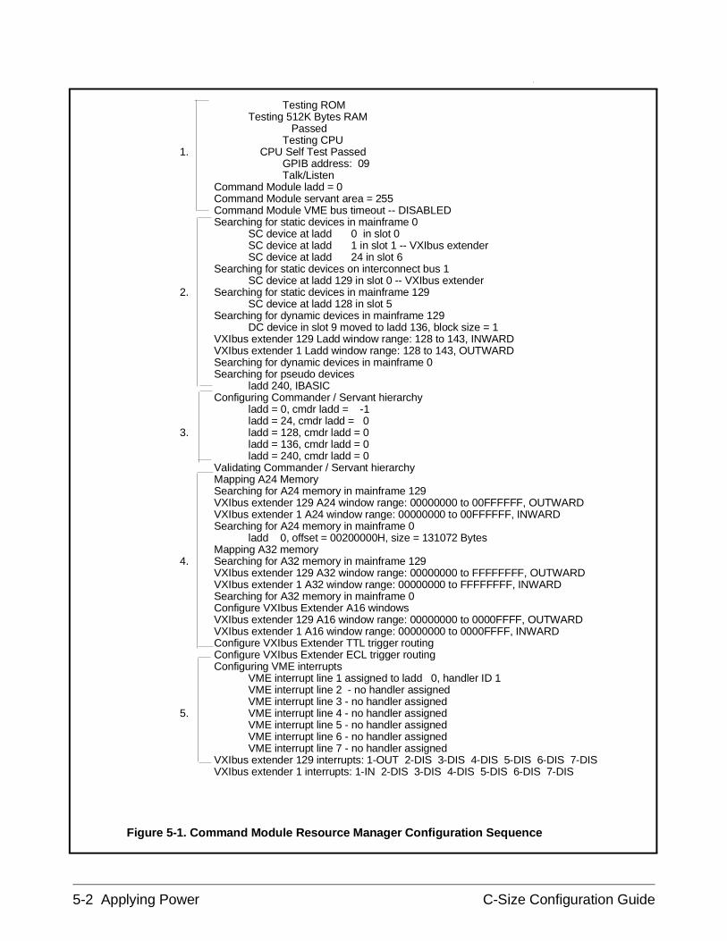
Testing ROMTesting 512K Bytes RAM
PassedTesting CPU
1. CPU Self Test PassedGPIB address: 09Talk/Listen
Command Module ladd = 0Command Module servant area = 255Command Module VME bus timeout -- DISABLEDSearching for static devices in mainframe 0
SC device at ladd 0 in slot 0SC device at ladd 1 in slot 1 -- VXIbus extenderSC device at ladd 24 in slot 6
Searching for static devices on interconnect bus 1SC device at ladd 129 in slot 0 -- VXIbus extender
2. Searching for static devices in mainframe 129SC device at ladd 128 in slot 5
Searching for dynamic devices in mainframe 129DC device in slot 9 moved to ladd 136, block size = 1
VXIbus extender 129 Ladd window range: 128 to 143, INWARDVXIbus extender 1 Ladd window range: 128 to 143, OUTWARDSearching for dynamic devices in mainframe 0Searching for pseudo devices
ladd 240, IBASICConfiguring Commander / Servant hierarchy
ladd = 0, cmdr ladd = -1ladd = 24, cmdr ladd = 0
3. ladd = 128, cmdr ladd = 0ladd = 136, cmdr ladd = 0ladd = 240, cmdr ladd = 0
Validating Commander / Servant hierarchyMapping A24 MemorySearching for A24 memory in mainframe 129VXIbus extender 129 A24 window range: 00000000 to 00FFFFFF, OUTWARDVXIbus extender 1 A24 window range: 00000000 to 00FFFFFF, INWARDSearching for A24 memory in mainframe 0
ladd 0, offset = 00200000H, size = 131072 BytesMapping A32 memory
4. Searching for A32 memory in mainframe 129VXIbus extender 129 A32 window range: 00000000 to FFFFFFFF, OUTWARDVXIbus extender 1 A32 window range: 00000000 to FFFFFFFF, INWARDSearching for A32 memory in mainframe 0Configure VXIbus Extender A16 windowsVXIbus extender 129 A16 window range: 00000000 to 0000FFFF, OUTWARDVXIbus extender 1 A16 window range: 00000000 to 0000FFFF, INWARDConfigure VXIbus Extender TTL trigger routingConfigure VXIbus Extender ECL trigger routingConfiguring VME interrupts
VME interrupt line 1 assigned to ladd 0, handler ID 1VME interrupt line 2 - no handler assignedVME interrupt line 3 - no handler assigned
5. VME interrupt line 4 - no handler assignedVME interrupt line 5 - no handler assignedVME interrupt line 6 - no handler assignedVME interrupt line 7 - no handler assigned
VXIbus extender 129 interrupts: 1-OUT 2-DIS 3-DIS 4-DIS 5-DIS 6-DIS 7-DISVXIbus extender 1 interrupts: 1-IN 2-DIS 3-DIS 4-DIS 5-DIS 6-DIS 7-DIS
Figure 5-1. Command Module Resource Manager Configuration Sequence
5-2 Applying Power C-Size Configuration Guide
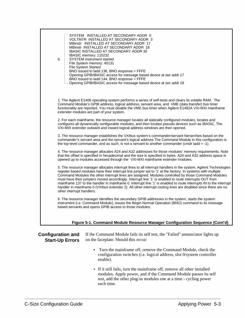
Configuration andStart-Up Errors
If the Command Module fails its self test, the "Failed" annunciator lights upon the faceplate. Should this occur:
• Turn the mainframe off, remove the Command Module, check theconfiguration switches (i.e. logical address, slot 0/system controllerenable).
• If it still fails, turn the mainframe off, remove all other installedmodules. Apply power, and if the Command Module passes its selftest, add the other plug-in modules one at a time - cycling powereach time.
SYSTEM INSTALLED AT SECONDARY ADDR 0VOLTMTR INSTALLED AT SECONDARY ADDR 3MBinstr INSTALLED AT SECONDARY ADDR 17MBinstr INSTALLED AT SECONDARY ADDR 18IBASIC INSTALLED AT SECONDARY ADDR 30IBASIC memory: 115232
6. SYSTEM instrument startedFile System memory: 40131File System StartedBNO issued to ladd 136, BNO response = FFFEOpening GPIB/IBASIC access for message based device at sec addr 17BNO issued to ladd 144, BNO response = FFFEOpening GPIB/IBASIC access for message based device at sec addr 18
1. The Agilent E1406 operating system performs a series of self-tests and clears its volatile RAM. TheCommand Module’s GPIB address, logical address, servant area, and VME (data transfer) bus timerfunctionality are reported. You must disable the VME bus timer when Agilent E1482A VXI-MXI mainframeextender modules are part of your system.
2. For each mainframe, the resource manager locates all statically configured modules, locates andconfigures all dynamically configurable modules, and then locates pseudo devices such as IBASIC. TheVXI-MXI extender outward and inward logical address windows are then opened.
3. The resource manager establishes the VXIbus system’s commander/servant hierarchies based on thecommander’s servant area and the servant’s logical address.The Command Module in this configuration isthe top-level commander, and as such, is not a servant to another commander (cmdr ladd = -1).
4. The resource manager allocates A24 and A32 addresses for those modules’ memory requirements. Notethat the offset is specified in hexadecimal and the size is specified in bytes. A24 and A32 address space isopened up to modules accessed through the VXI-MXI mainframe extender modules.
5. The resource manager allocates interrupt lines to all interrupt handlers in the system. Agilent Technologiesregister-based modules have their interrupt line jumper set to ’1’ at the factory. In systems with multipleCommand Modules the other interrupt lines are assigned. Modules controlled by those Command Modulesmust have their jumpers moved accordingly. Interrupt line ’1’ is enabled to route interrupts OUT frommainframe 137 to the handler in mainframe 0. Interrupt line ’1’ is enabled to route interrupts IN to the interrupthandler in mainframe 0 (VXIbus extender 2). All other interrupt routing lines are disabled since there are noother interrupt handlers.
6. The resource manager identifies the secondary GPIB addresses in the system, starts the systeminstrument (i.e. Command Module), issues the Begin Normal Operation (BNO) command to its messagebased servants and opens GPIB access to those modules.
Figure 5-1. Command Module Resource Manager Configuration Sequence (Cont’d)
C-Size Configuration Guide Applying Power 5-3
• if necessary, call your nearest Agilent Technologies sales and serviceoffice.
When using the Command Module for the first time or when the mainframehas not been turned on for at least one week, leave the mainframe on for atleast 15 hours to fully charge the Command Module’s battery.
If a configuration or start-up error such as an invalid address or failed selftest occurs, the error is reported in the power-on and configurationsequence. A list of the configuration and start-up error messages and theircauses can be found at the end of this guide.
HP 9000 Series 700Computer
To verify that the E1482B VXIbus extender module, the MXIbus and INTXcables, and all VXI instruments are correctly installed, turn on themainframe. This starts the system resource manager function (ivxirm)provided by the Agilent E1489I MXIbus Controller Interface card and the Agilent E2093B SICL software. To view the contents of the configurationfile (rsrcmgr.out) written to by the resource manager, type the followingcommand:
/usr/pil/bin/ivxisc
An example of a configuration file (sequence) is shown in Figure 5-2.
5-4 Applying Power C-Size Configuration Guide
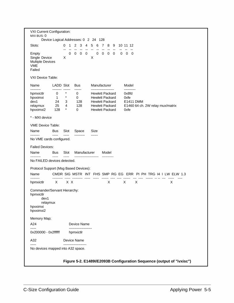
VXI Current Configuration:MXI BUS: 0
Device Logical Addresses: 0 2 24 128
Slots: 0 1 2 3 4 5 6 7 8 9 10 11 12-- -- -- -- -- -- -- -- -- -- -- -- --
Empty 0 0 0 0 0 0 0 0 0 0 0Single Device X XMultiple DevicesVMEFailed
VXI Device Table:
Name LADD Slot Bus Manufacturer Model--------- -------- ------ ------ -------------------- ----------hpmxictlr 0 * 0 Hewlett Packard 0x8fdhpvximxi 1 * 0 Hewlett Packard 0xfedev1 24 3 128 Hewlett Packard E1411 DMMrelaymux 25 4 128 Hewlett Packard E1460 64 ch. 2W relay mux/matrixhpvximxi2 128 * 0 Hewlett Packard 0xfe
* - MXI device
VME Device Table:
Name Bus Slot Space Size-------- ----- ----- --------- ------No VME cards configured.
Failed Devices:
Name Bus Slot Manufacturer Model--------- ----- ----- --------------------- ----------No FAILED devices detected.
Protocol Support (Msg Based Devices):
Name CMDR SIG MSTR INT FHS SMP RG EG ERR PI PH TRG I4 I LW ELW 1.3-------- --------- ----- --------- ----- ----- ------ ---- ---- ------ --- ---- ------ -- -- --- ----- ----hpmxictlr X X X X X X X
Commander/Servant Hierarchy:hpmxictlr
dev1relaymux
hpvximxihpvximxi2
Memory Map;
A24 Device Name----- --------------------0x200000 - 0x2ffffff hpmxictlr
A32 Device Name----- --------------------No devices mapped into A32 space.
Figure 5-2. E1489I/E2093B Configuration Sequence (output of "ivxisc")
C-Size Configuration Guide Applying Power 5-5
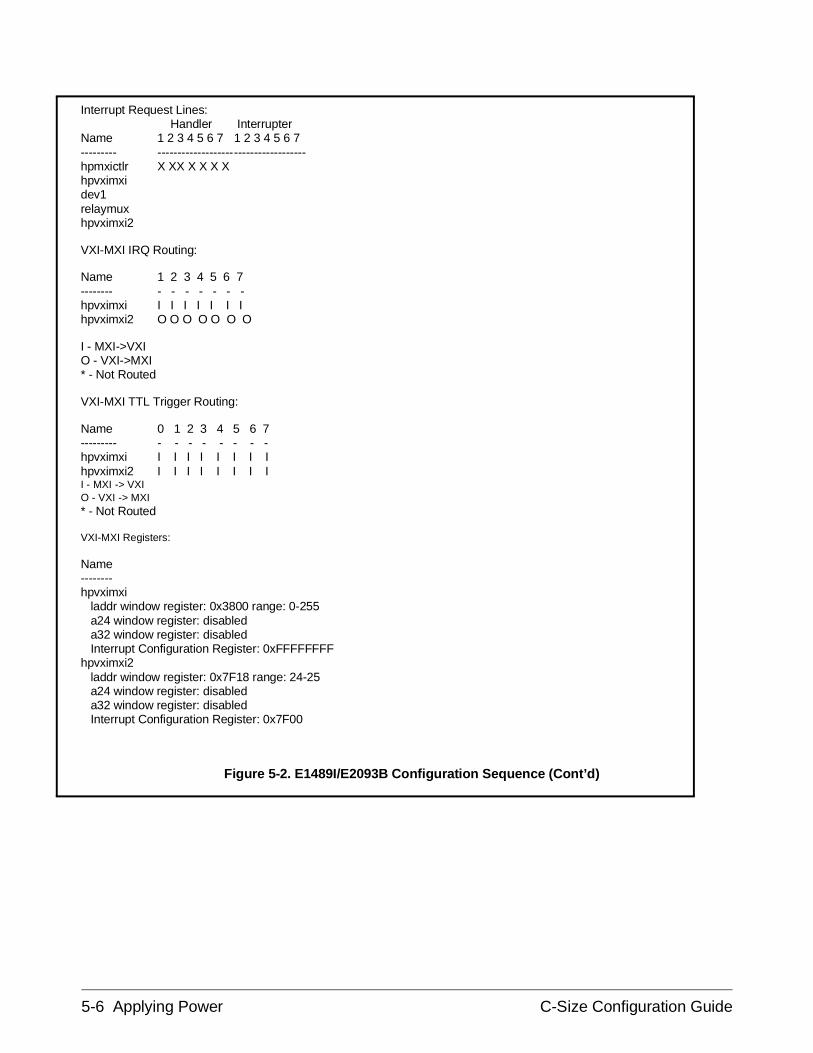
Interrupt Request Lines: Handler Interrupter
Name 1 2 3 4 5 6 7 1 2 3 4 5 6 7--------- -------------------------------------hpmxictlr X XX X X X Xhpvximxidev1relaymuxhpvximxi2
VXI-MXI IRQ Routing:
Name 1 2 3 4 5 6 7-------- - - - - - - -hpvximxi I I I I I I Ihpvximxi2 O O O O O O O
I - MXI->VXIO - VXI->MXI* - Not Routed
VXI-MXI TTL Trigger Routing:
Name 0 1 2 3 4 5 6 7--------- - - - - - - - -hpvximxi I I I I I I I Ihpvximxi2 I I I I I I I II - MXI -> VXIO - VXI -> MXI* - Not Routed
VXI-MXI Registers:
Name--------hpvximxi laddr window register: 0x3800 range: 0-255 a24 window register: disabled a32 window register: disabled Interrupt Configuration Register: 0xFFFFFFFFhpvximxi2 laddr window register: 0x7F18 range: 24-25 a24 window register: disabled a32 window register: disabled Interrupt Configuration Register: 0x7F00
Figure 5-2. E1489I/E2093B Configuration Sequence (Cont’d)
5-6 Applying Power C-Size Configuration Guide
Agilent E1497A/E1498A Embedded
V743 Controller
To verify that the V743 controller-based system is installed correctly, turnon the mainframe. If configured, this starts the system resource manager(ivxirm) provided by the V743. To view the contents of the configurationfile (/usr/pil/etc/vxiLU/rsrcmgr.out) written to by ivxirm, type the followingcommand:
ivxisc /usr/pil/etc/vxiLU
Where LU is the logical unit number of the VXI interface. An example ofthe V743 configuration sequence is shown in Figure 5-3.
C-Size Configuration Guide Applying Power 5-7
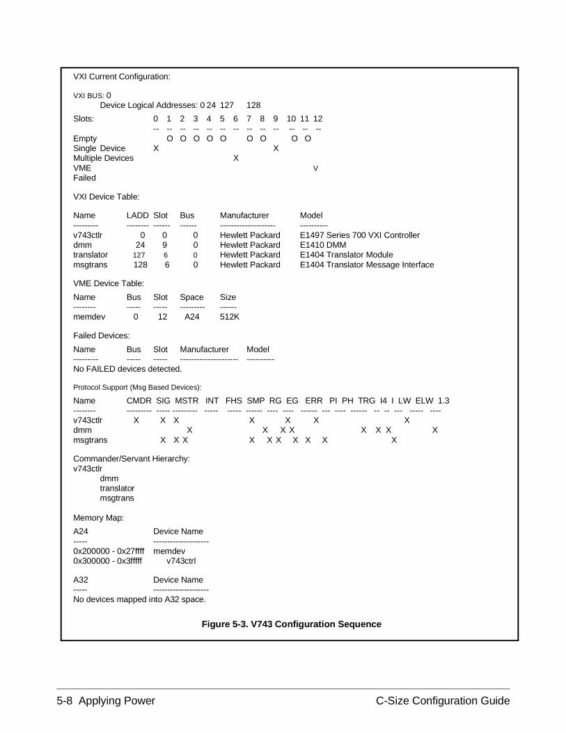
VXI Current Configuration:
VXI BUS: 0Device Logical Addresses: 0 24 127 128
Slots: 0 1 2 3 4 5 6 7 8 9 10 11 12-- -- -- -- -- -- -- -- -- -- -- -- --
Empty O O O O O O O O O Single Device X XMultiple Devices XVME VFailed
VXI Device Table:
Name LADD Slot Bus Manufacturer Model--------- -------- ------ ------ -------------------- ----------v743ctlr 0 0 0 Hewlett Packard E1497 Series 700 VXI Controllerdmm 24 9 0 Hewlett Packard E1410 DMMtranslator 127 6 0 Hewlett Packard E1404 Translator Modulemsgtrans 128 6 0 Hewlett Packard E1404 Translator Message Interface
VME Device Table:
Name Bus Slot Space Size-------- ----- ----- --------- ------memdev 0 12 A24 512K
Failed Devices:
Name Bus Slot Manufacturer Model--------- ----- ----- --------------------- ----------No FAILED devices detected.
Protocol Support (Msg Based Devices):
Name CMDR SIG MSTR INT FHS SMP RG EG ERR PI PH TRG I4 I LW ELW 1.3-------- --------- ----- --------- ----- ----- ------ ---- ---- ------ --- ---- ------ -- -- --- ----- ----v743ctlr X X X X X X Xdmm X X X X X X X Xmsgtrans X X X X X X X X X X
Commander/Servant Hierarchy:v743ctlr
dmmtranslatormsgtrans
Memory Map:
A24 Device Name----- --------------------0x200000 - 0x27ffff memdev0x300000 - 0x3fffff v743ctrl
A32 Device Name----- --------------------No devices mapped into A32 space.
Figure 5-3. V743 Configuration Sequence
5-8 Applying Power C-Size Configuration Guide
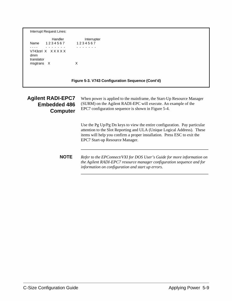
Agilent RADI-EPC7Embedded 486
Computer
When power is applied to the mainframe, the Start-Up Resource Manager(SURM) on the Agilent RADI-EPC will execute. An example of the EPC7 configuration sequence is shown in Figure 5-4.
Use the Pg Up/Pg Dn keys to view the entire configuration. Pay particularattention to the Slot Reporting and ULA (Unique Logical Address). Theseitems will help you confirm a proper installation. Press ESC to exit theEPC7 Start-up Resource Manager.
NOTE Refer to the EPConnect/VXI for DOS User’s Guide for more information onthe Agilent RADI-EPC7 resource manager configuration sequence and forinformation on configuration and start up errors.
Interrupt Request Lines:
Handler InterrupterName 1 2 3 4 5 6 7 1 2 3 4 5 6 7- - - - - - - - - - - - - - - - - -V743ctrl X X X X X Xdmmtranslatormsgtrans X X
Figure 5-3. V743 Configuration Sequence (Cont’d)
C-Size Configuration Guide Applying Power 5-9
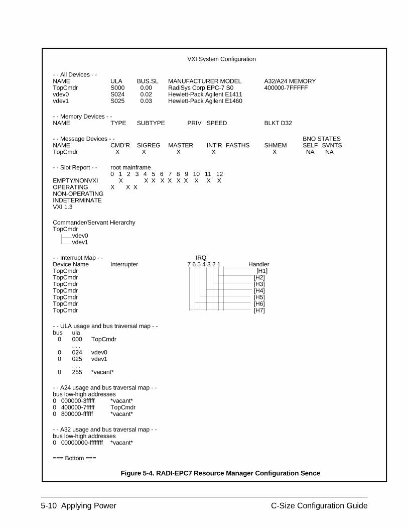
VXI System Configuration
- - All Devices - -NAME ULA BUS.SL MANUFACTURER MODEL A32/A24 MEMORYTopCmdr S000 0.00 RadiSys Corp EPC-7 S0 400000-7FFFFFvdev0 S024 0.02 Hewlett-Pack Agilent E1411vdev1 S025 0.03 Hewlett-Pack Agilent E1460
- - Memory Devices - -NAME TYPE SUBTYPE PRIV SPEED BLKT D32
- - Message Devices - - BNO STATESNAME CMD’R SIGREG MASTER INT’R FASTHS SHMEM SELF SVNTSTopCmdr X X X X X NA NA
- - Slot Report - - root mainframe0 1 2 3 4 5 6 7 8 9 10 11 12
EMPTY/NONVXI X X X X X X X X X XOPERATING X X XNON-OPERATINGINDETERMINATEVXI 1.3
Commander/Servant HierarchyTopCmdr
vdev0vdev1
- - Interrupt Map - - IRQDevice Name Interrupter 7 6 5 4 3 2 1 HandlerTopCmdr [H1]TopCmdr [H2]TopCmdr [H3]TopCmdr [H4]TopCmdr [H5]TopCmdr [H6]TopCmdr [H7]
- - ULA usage and bus traversal map - -bus ula 0 000 TopCmdr
. . . 0 024 vdev0 0 025 vdev1
. . . 0 255 *vacant*
- - A24 usage and bus traversal map - -bus low-high addresses0 000000-3fffff *vacant*0 400000-7fffff TopCmdr0 800000-ffffff *vacant*
- - A32 usage and bus traversal map - -bus low-high addresses0 00000000-ffffffff *vacant*
=== Bottom ===
Figure 5-4. RADI-EPC7 Resource Manager Configuration Sence
5-10 Applying Power C-Size Configuration Guide
SettingCommander/Servant
Hierarchies whenusing a Command
Module
When you have an EPC7, Command Module, and Agilent register-basedinstruments to be accessed via GPIB in the same system, you must changethe commander/servant hierarchy and interrupt mapping so that selectedinstruments report to the Command Module instead of the EPC7. Changingthe commander/servant hierarchy involves the following:
• Verifying instruments in the database• Assigning VXI device names• Assigning Commander/Servant Hierarchy• Assigning interrupt lines
Each procedure is described in following sections and can be run byopening the VXI Configurator icon in the EPConnect Program Group. Seethe EPC7 documentation for additional information on these procedures.
Verifying Instruments in the Database
1. From Windows, select the VXI Configurator icon.
2. Select Database and scroll to Models.
3. Verify that your instruments are listed in the database. If you needto add an instrument, fill in the data and select the Add button. Thefollowing is an example of adding an Agilent E1406A :
– Select Manufacturer - Hewlett-Pack– Enter Model - Agilent E1406A– Enter Model number - 276 (This is the model code printed on
side of the instrument.)– Select the Add button
Repeat this step for each instrument that needs to be added to thedatabase.
4. Select OK to end.
Assigning VXI Device Names
1. From the VXI Configurator, select Devices and scroll to VXI.
2. Each instrument in your system needs to have a device nameassigned. The following in an example of assigning a name to theE1406A Command Module:
– Enter a device name in the Name field - Cmdmod– Select the device from the Manufacturer/Model menu -
Hewlett-Pack Agilent E1406 276
– Clear the Location and Logical address check boxes.
C-Size Configuration Guide Applying Power 5-11
– Select the Add button.
Repeat this procedure for each VXI instrument in your system.
3. Select OK to end.
Assigning Commander/Servant Hierarchy
1. From the VXI Configurator, select VXI Control and scroll toCommander hierarchy.
2. Select the commander (Cmdmod, for example) from the All knownnames box and select the Add commander button. Thecommander added will now be shown in the Commanders box.
3. Now, select the commander (Cmdmod, for example) from theCommanders box and select the device you want to add as aservant in the All known names box. Select the Add servantbutton to add the device as a servant to the commander. (Thedevices listed in the All known names box are the same devicesyou assigned names in the "Assigning VXI Device Names" section.)
Repeat this step for each device to add as a servant to thecommander.
4. Select OK to end.
Assigning Interrupt Lines
1. From the VXI Configurator, select VXI Control and scroll toInterrupt mapping.
2. Select the Commander (Cmdmod, for example) from the Selecteddevice box.
3. Clear the Assign IRQs at runtime box so that you can assigninterrupt lines to the selected commander. Assign the interruptlines as follows:
– In the attributes box, assign interrupt line 1 to the commander byplacing a 1 under H 1 in the Handlers, IRQ number or 0 box.
– Select the Change button to change interrupt line assignments.
4. If you now have two commanders assigned to interrupt line 1, selectthe other commander and change H1 in the Handlers, IRQnumber or 0 box so that interrupt line 1 is assigned only to theCommand Module.
5. Select OK to end.
5-12 Applying Power C-Size Configuration Guide
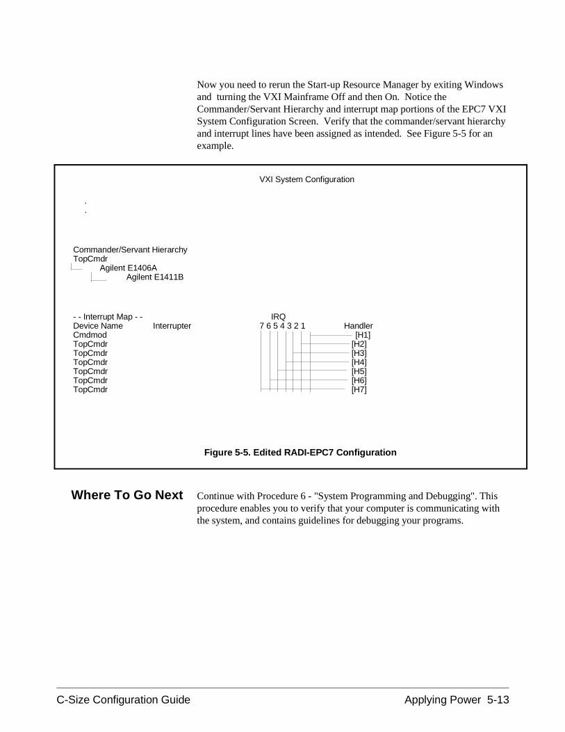
Now you need to rerun the Start-up Resource Manager by exiting Windowsand turning the VXI Mainframe Off and then On. Notice theCommander/Servant Hierarchy and interrupt map portions of the EPC7 VXISystem Configuration Screen. Verify that the commander/servant hierarchyand interrupt lines have been assigned as intended. See Figure 5-5 for anexample.
Where To Go Next Continue with Procedure 6 - "System Programming and Debugging". Thisprocedure enables you to verify that your computer is communicating withthe system, and contains guidelines for debugging your programs.
VXI System Configuration
. .
Commander/Servant HierarchyTopCmdr
Agilent E1406AAgilent E1411B
- - Interrupt Map - - IRQDevice Name Interrupter 7 6 5 4 3 2 1 HandlerCmdmod [H1]TopCmdr [H2]TopCmdr [H3]TopCmdr [H4]TopCmdr [H5]TopCmdr [H6]TopCmdr [H7]
Figure 5-5. Edited RADI-EPC7 Configuration
C-Size Configuration Guide Applying Power 5-13

5-14 Applying Power C-Size Configuration Guide
Procedure 6: System Programming and Debugging
After your instruments have been installed in the VXI mainframe, the nextstep is to program them. This procedure outlines a general approach tobegin communicating with the instruments and for debugging yourprograms. The steps within this procedure include:
Communication
• COMM1 : Verify communication with the instruments.
Debugging Programs
• DEBUG1 : Sending SCPI Commands
• DEBUG2 : Verify the System Logical Addresses
• DEBUG3 : Start Each Program by Fully Resetting Each Instrument
• DEBUG4 : Query the Instrument for Errors
• DEBUG5 : Query all Command Parameter Settings
• DEBUG6 : Verify that the Amount of Data to be Entered is Equal tothe Amount of Data Generated
• DEBUG7 : Check the Instrument’s Arm-Trigger Subsystem
• DEBUG8 : Execute Coupled Commands Within a Coupling Group
• DEBUG9 : Check for Command Synchronization Errors
C-Size Configuration Guide System Programming and Debugging 6-1
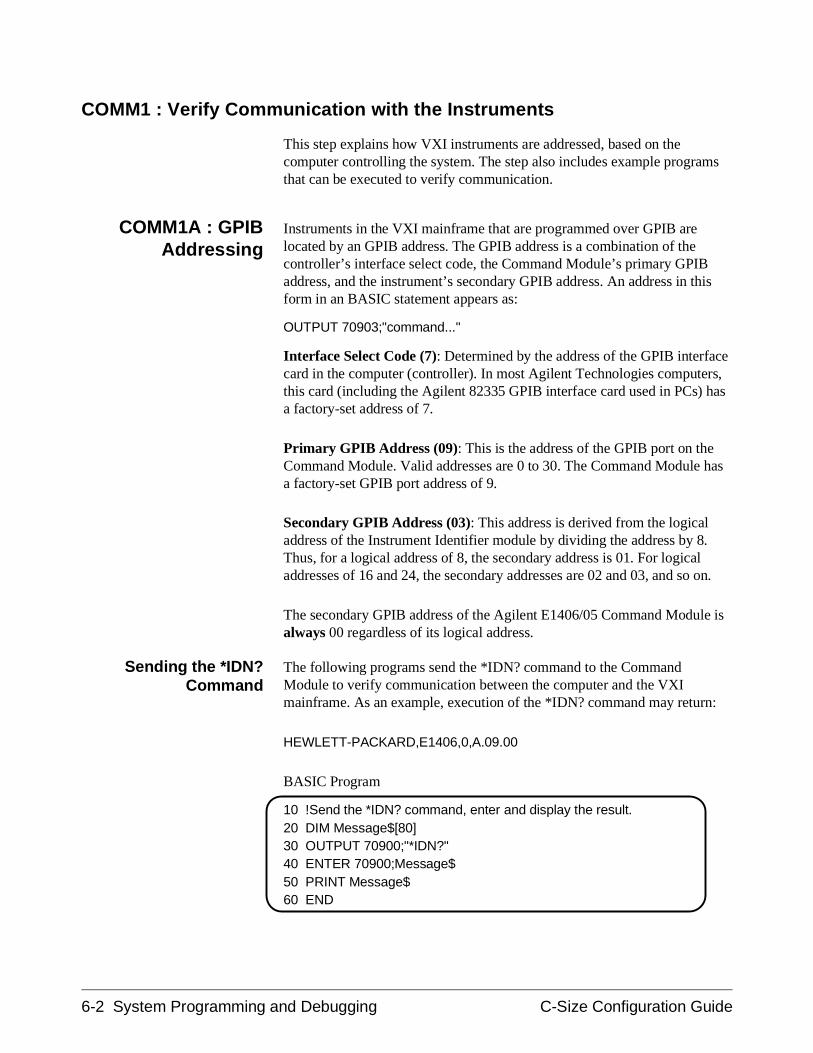
COMM1 : Verify Communication with the Instruments
This step explains how VXI instruments are addressed, based on thecomputer controlling the system. The step also includes example programsthat can be executed to verify communication.
COMM1A : GPIBAddressing
Instruments in the VXI mainframe that are programmed over GPIB arelocated by an GPIB address. The GPIB address is a combination of thecontroller’s interface select code, the Command Module’s primary GPIBaddress, and the instrument’s secondary GPIB address. An address in thisform in an BASIC statement appears as:
OUTPUT 70903;"command..."
Interface Select Code (7): Determined by the address of the GPIB interfacecard in the computer (controller). In most Agilent Technologies computers,this card (including the Agilent 82335 GPIB interface card used in PCs) hasa factory-set address of 7.
Primary GPIB Address (09): This is the address of the GPIB port on theCommand Module. Valid addresses are 0 to 30. The Command Module hasa factory-set GPIB port address of 9.
Secondary GPIB Address (03): This address is derived from the logicaladdress of the Instrument Identifier module by dividing the address by 8.Thus, for a logical address of 8, the secondary address is 01. For logicaladdresses of 16 and 24, the secondary addresses are 02 and 03, and so on.
The secondary GPIB address of the Agilent E1406/05 Command Module isalways 00 regardless of its logical address.
Sending the *IDN?Command
The following programs send the *IDN? command to the CommandModule to verify communication between the computer and the VXImainframe. As an example, execution of the *IDN? command may return:
HEWLETT-PACKARD,E1406,0,A.09.00
BASIC Program
10 !Send the *IDN? command, enter and display the result.20 DIM Message$[80]30 OUTPUT 70900;"*IDN?"40 ENTER 70900;Message$50 PRINT Message$60 END
6-2 System Programming and Debugging C-Size Configuration Guide
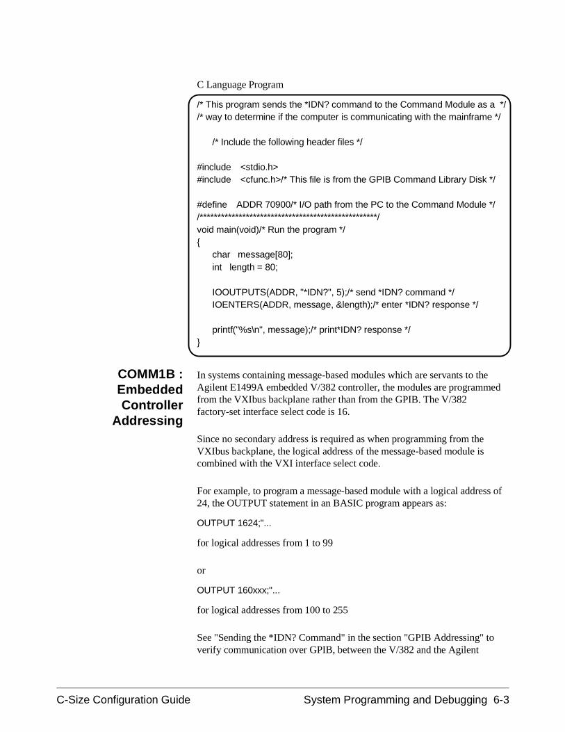
C Language Program
/* This program sends the *IDN? command to the Command Module as a *//* way to determine if the computer is communicating with the mainframe */
/* Include the following header files */
#include <stdio.h>#include <cfunc.h>/* This file is from the GPIB Command Library Disk */
#define ADDR 70900/* I/O path from the PC to the Command Module *//**************************************************/void main(void)/* Run the program */
char message[80];int length = 80;
IOOUTPUTS(ADDR, "*IDN?", 5);/* send *IDN? command */IOENTERS(ADDR, message, &length);/* enter *IDN? response */
printf("%s\n", message);/* print*IDN? response */
COMM1B :EmbeddedController
Addressing
In systems containing message-based modules which are servants to the Agilent E1499A embedded V/382 controller, the modules are programmedfrom the VXIbus backplane rather than from the GPIB. The V/382factory-set interface select code is 16.
Since no secondary address is required as when programming from theVXIbus backplane, the logical address of the message-based module iscombined with the VXI interface select code.
For example, to program a message-based module with a logical address of24, the OUTPUT statement in an BASIC program appears as:
OUTPUT 1624;"...
for logical addresses from 1 to 99
or
OUTPUT 160xxx;"...
for logical addresses from 100 to 255
See "Sending the *IDN? Command" in the section "GPIB Addressing" toverify communication over GPIB, between the V/382 and the Agilent
C-Size Configuration Guide System Programming and Debugging 6-3
E1406/05 Command Module. See the sections "SICL Addressing" and"Compiled SCPI Addressing" for programs to verify communication withV/382 HP-UX operating systems.
COMM1C : SICLAddressing
In systems using the Standard Instrument Command Language (SICL), acommunication channel must be opened between the computer and a VXIinstrument. This communication channel is referred to as a device session.A device session is opened by specifying a device address within theIOPEN function. For example:
instrument = iopen("vxi,24");
opens a device session over the VXIbus between the computer and the VXIinstrument at logical address 24. Similarly:
instrument = iopen("hpib,9,3");
opens a device session over GPIB between the computer and the VXIinstrument at secondary GPIB address 3 (logical address 24).
Sending the *IDN?Command
The following SICL program sends the *IDN? command to the AgilentE1411B multimeter to verify communication between the computer and theVXI mainframe. As an example, execution of the *IDN? command mayreturn:
HEWLETT-PACKARD,E1411B,0,B.05.00
6-4 System Programming and Debugging C-Size Configuration Guide
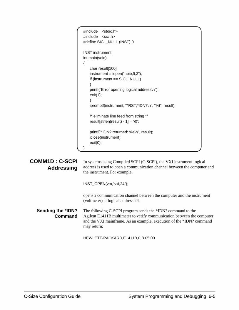
#include <stdio.h>#include <sicl.h>#define SICL_NULL (INST) 0 INST instrument;int main(void)
char result[100];instrument = iopen("hpib,9,3");if (instrument == SICL_NULL)printf("Error opening logical address\n"); exit(1); ipromptf(instrument, "*RST;*IDN?\n", "%t", result);
/* eliminate line feed from string */result[strlen(result) - 1] = ’\0’;
printf("*IDN? returned: %s\n", result);iclose(instrument);exit(0);
COMM1D : C-SCPIAddressing
In systems using Compiled SCPI (C-SCPI), the VXI instrument logicaladdress is used to open a communication channel between the computer andthe instrument. For example,
INST_OPEN(vm,"vxi,24");
opens a communication channel between the computer and the instrument(voltmeter) at logical address 24.
Sending the *IDN?Command
The following C-SCPI program sends the *IDN? command to the Agilent E1411B multimeter to verify communication between the computerand the VXI mainframe. As an example, execution of the *IDN? commandmay return:
HEWLETT-PACKARD,E1411B,0,B.05.00
C-Size Configuration Guide System Programming and Debugging 6-5
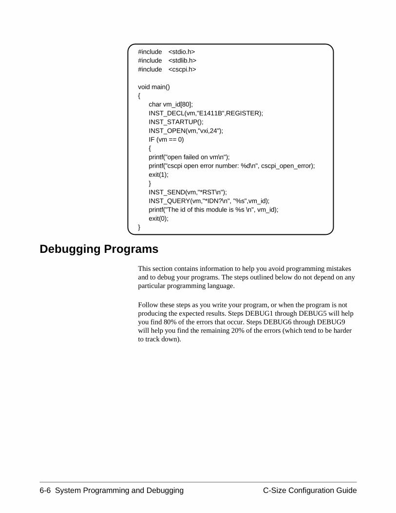
#include <stdio.h>#include <stdlib.h>#include <cscpi.h>
void main()
char vm_id[80];INST_DECL(vm,"E1411B",REGISTER);INST_STARTUP();INST_OPEN(vm,"vxi,24");IF (vm == 0)printf("open failed on vm\n");printf("cscpi open error number: %d\n", cscpi_open_error);exit(1);INST_SEND(vm,"*RST\n");INST_QUERY(vm,"*IDN?\n", "%s",vm_id);printf("The id of this module is %s \n", vm_id);exit(0);
Debugging Programs
This section contains information to help you avoid programming mistakesand to debug your programs. The steps outlined below do not depend on anyparticular programming language.
Follow these steps as you write your program, or when the program is notproducing the expected results. Steps DEBUG1 through DEBUG5 will helpyou find 80% of the errors that occur. Steps DEBUG6 through DEBUG9will help you find the remaining 20% of the errors (which tend to be harderto track down).
6-6 System Programming and Debugging C-Size Configuration Guide
DEBUG1 : Sending SCPI Commands
Standard Commands for Programmable Instruments (SCPI) is anASCII-based instrument command language designed for test andmeasurement instruments. The Agilent E1406/05 Command Moduleinterprets the ASCII command strings for its register-based servantmodules. Agilent Technologies message-based modules have an on-boardmicroprocessor which makes them capable of interpreting the commandstrings themselves.
SCPI CommandStructure
SCPI commands are based on a hierarchical structure, also known as a treesystem. In this system, associated commands are grouped together under acommon node or root, thus, forming subtrees or subsystems. An example isthe Agilent E1445A Arbitrary Function Generator’s "ARM" subsystem.
ARM[:STARt|SEQuence[1]]
[:LAYer[1]] :COUNt <number>
:LAYer2 :COUNt <number>[:IMMediate] [no query]:SLOPe <edge>:SOURce <source>
:SWEep|SEQuence3:COUNt <number>[:IMMediate] [no query]:LINK <link>:SOURce <source>
ARM is the root keyword of the command, :STARt|SEQuence1 and:SWEep|SEQuence3 are second level keywords, :LAYer1 and :LAYer2 arethird level keywords, and so on. A colon (:) always separates a commandkeyword from a lower level keyword as shown below.
ARM:LAY2:SOUR EXT
A semicolon (;) is used to separate two commands within the samesubsystem, and can also save typing. For example, sending this commandmessage:
ARM:LAY2:SOUR EXT;SLOP POS;COUN 10
is the same as sending these three commands:
C-Size Configuration Guide System Programming and Debugging 6-7
ARM:LAY2:SOUR EXT
ARM:LAY2:SLOP POS
ARM:LAY2:COUN 10
Note that the semicolon (;) and colon (:) link commands within differentsubsystems. Only a semicolon (;) is required to link commands within thesame subsystem.
Terminating Commands All command sequences must end with a proper terminator called aprogram message terminator. This may be a Line Feed (LF), Line Feed withEOI (End-Or-Identify), or EOI. Most programming systems provide somemethod of specifying the terminator. BASIC for example, automaticallyprovides a Line Feed at the end of all OUTPUT statements.
Data returned from a VXI instrument will always terminate with a LineFeed and EOI. BASIC ENTER statements will terminate with this.
DEBUG2 : Verify the System Logical Addresses
One of the most common errors encountered is a logical address that is setincorrectly. A common mistake is to interpret the most-significant-bit(MSB) for the least-significant-bit (LSB), or to interpret a 1 setting for a 0setting.
Use the VXI:CONF:LADD? command to return a list of all logicaladdresses in the system. This allows you to verify that the system sees theswitch settings as you intended.
/* reserve computer memory (approximately 128 bytes) for the data */ /* returned */VXI:CONF:LADD?/* enter and print results of command */
These logical addresses, divided by eight, are the secondary (GPIB)addresses of the instruments in the system.
You can execute the following query to find additional information about aninstrument at a specific logical address:
/* select the instrument at logical address 24 */VXI:SEL 24/* send INFormation? command to receive information on the instrument *//* enter and print the data returned */VXI:CONF:INF?
6-8 System Programming and Debugging C-Size Configuration Guide
DEBUG3 : Start Each Program by Fully Resetting Each Instrument
An instrument is fully reset when you cycle power or go through the threelevels of the reset hierarchy. It is important to go through all levels in theproper order because some instruments can set conditions that can only beaborted by this sequence.
1. Issue an IEEE-488 Interface clear which will remove any busdeadlocks. (i.e. ABORT 7)
2. Issue an IEEE-488 selected device clear which will terminateinstrument activity and clear the input/output buffers (i.e. CLEAR70900).
3. Reset each instrument and wait for the reset to complete.
*RST;*CLS;*ESE 0;*SRE 0;*OPC?
/* enter the data (1) returned by *OPC? */
*RST resets the instrument.
*CLS;*ESE 0;*SRE 0 resets the instrument’s status subsystem thatis defined by IEEE 488.2.
*OPC? outputs a “1” when all commands before it have completed.
DEBUG4 : Query the Instrument for Errors
SCPI defines that all instruments will have an error queue. Any time anerror occurs, a message is placed in this queue. This error queue is read bysending the SYST:ERR? command.
Knowing that the error queue exists and reading it frequently is one of themost important things to do. Another common problem is to send acommand string that has a syntax error. When the command is parsed andthe error is detected, a message is written to the error queue. However, noother action is taken as the instrument does not know what the commandwas supposed to do. Generally, no indication of an error is given, andreading the error queue is the only way to get feedback if an error isdetected.
/* repeat */SYST:ERR?
/* enter and print error data *//* until there are no more errors in the queue */
C-Size Configuration Guide System Programming and Debugging 6-9
DEBUG5 : Query all Command Parameter Settings
When the error queue contains an error, the next task is to determine whichcommand caused it. When a command has an error, it is not executed. Aneffective debugging technique is to query previously sent commands fortheir current settings. When a queried setting doesn’t match what was to beset, then the error exists in the corresponding command.
The most common command-related errors are:
– misspelled commands
– eliminating the space between the command and the firstparameter
– parameters out of range
– settings conflict errors caused by coupled commands notexecuted within a coupling group
DEBUG6 : Verify that the Amount of Data to be Entered is Equal to theAmount of Data Generated
Another error which frequently occurs is not receiving the exact amount ofdata expected from the instrument. Check the parameter settings as in stepDEBUG5, and then compare this with the number of data itemsprogrammed to receive. Also notice whether arrays start with zero or one.Multiple results to one query command will be separated by commas.
6-10 System Programming and Debugging C-Size Configuration Guide
DEBUG7 : Check the Instrument’s Arm-Trigger Subsystem
All SCPI instruments follow an Arm-Trigger model that is described inmost operating manuals and in the "Beginner’s Guide to SCPI" document.This model has both required and optional levels:
IDLE requiredARM:LAYer<x> optionalARM:LAYer<2> optionalARM:LAYer1 optionalINITIATED requiredTRIGger optionalsequence operation required
The Arm-Trigger subsystem starts with the IDLE state which occurs atpower-on, following ABORT or *RST, or after a previous Arm-Triggercycle that has completed.
Command configuration occurs when the instrument is in the IDLE state.After the instrument has been configured (including its ARM and TRIGgerfunctions), the INITiate command is executed which moves the instrumentto the INITIATED state. Once initiated, reception of the appropriate armand trigger signals start the sequence operation.
Since each instrument may implement different ARM layers, TRIGgersources, etc., refer to the operating manual for information on the exactARM/TRIGger sequence used.
An example ARM/TRIGger sequence follows:
/* Program a Function Generator to output 100 cycles of a waveformwhenever a signal is applied to its "Aux In" port */
/* Arm source = Aux In port source */ARM:STAR:LAY2:SOUR EXT;
/* Infinite number of Aux In arms */ARM:STAR:LAY2:COUN INF;
/* 100 cycles */ARM:STAR:LAY1:COUN 1E2
/* Initiate the waveform (trigger source internal) */INIT
C-Size Configuration Guide System Programming and Debugging 6-11
DEBUG8 : Execute Coupled Commands Within a Coupling Group
Certain SCPI commands are functional coupled or value coupled.Functionally coupled commands are those that for one command to haveaffect, another command must be set to a particular value. Value coupledcommands are those where changing the value of one command, changesthe value of the others.
Coupled commands can cause “Settings conflict” errors when the programexecutes. When a coupled command is executed, the command setting isevaluated by the Command Module’s (or message-based instrument’s)processor. If the setting causes an illegal digitizer configuration, a "Settingsconflict" error occurs. The error message lists the conflicting settings, andthen reports the values set by the processor.
The "Comments" section of each command reference entry in theinstrument manual usually indicates if a command is coupled, and if it is,what the coupling constraints are.
How to ExecuteCoupled Commands
To prevent possible "Settings conflict" errors, coupled commands must becontiguous and executed in the same program statement. This is done byplacing the commands in the same program line, or for BASIC programs,by suppressing the EOL terminator until the last (coupled) command hasbeen sent.
To send multiple commands in a single line or in a single statement, thecommands are linked with a semicolon (;) and a colon (:). This is illustratedin the following lines:
OUTP:EXT1:STAT ON;:TRIG:SOUR EXT1;:OUTP:EXT1:STAT OFF
or
OUTP:EXT1:STAT ON;
:TRIG:SOUR EXT1;
:OUTP:EXT1:STAT OFF
Notice that the semicolon (;) and colon (:) link commands within differentsubsystems. Only a semicolon (;) is required to link commands at the samelevel within the same subsystem.
6-12 System Programming and Debugging C-Size Configuration Guide
In an instrument where the previous commands are coupled, sending thecommands as shown prevents "Settings conflict" errors. The commandsettings are not evaluated until the EOL terminator is received after the lastcommand. If these commands were sent individually (an EOL terminatorafter each command), a "Settings conflict" error would occur because of thecoupling between OUTP:EXT1:STAT ON and TRIG:SOUR EXT1.
DEBUG9 : Check for Command Synchronization Errors
IEEE 488.2 specifies that all instruments will have an input buffer and thatexecution of these commands does not start until a program messageterminator is received (i.e. Line Feed, Line Feed with EOI, or EOI).
A common problem is the computer will send commands to the inputbuffers of two instruments. It is possible that the second instrument mayexecute its commands before the first instrument executes the commands.Thus, instruments may execute their functions in an order that is differentfrom the command sequence in the computer program.
Synchronization of instrument-to-computer is accomplished by sending acommand that returns data. The computer must wait for the data to bereturned. The *OPC? command defined by IEEE 488.2 was created for thispurpose. *OPC? will return a one (1) when the commands before it havefinished executing.
The following example closes four relays and waits for the command tocomplete before continuing with the next command:
CLOSE (@100,101,102,103);*OPC?/* enter the data returned by *OPC? (1) */READ?
C-Size Configuration Guide System Programming and Debugging 6-13

6-14 System Programming and Debugging C-Size Configuration Guide
Appendix A:Terms and Definitions
This chapter contains additional information on specific terms and functionsrefereed to in the procedures throughout this manual. The following topicsare covered:
• Resource Manager.........................................................A-2• Slot 0 Functionality.......................................................A-2• 10 MHz Clock Source...................................................A-3• Bus Request Level ........................................................A-3• Command Module Memory..........................................A-4• Servant Area..................................................................A-5• Primary GPIB Address .................................................A-7• VXI-MXI Interface .......................................................A-8• What is an Instrument Identifier? .................................A-9• Virtual Instruments .......................................................A-9• Logical Address ............................................................A-10• Downloadable Instrument Drivers................................A-11• Display Terminals .........................................................A-12• Interrupt Lines...............................................................A-12
C-Size Configuration Guide Terms and Definitions A-1
What is theResource Manager?
Every VXIbus system must have a module that provides the system’sresource manager requirements. The resource manager function in moduleswith this capability, such as the Command Module, is activated by settingthe logical address to 0.
At power-on, the resource manager function is started. The purpose of theresource manager is to:
• identify all plug-in modules installed in the C-size mainframe
• set commander/servant hierarchies whereby one or more plug-inmodules control other plug-in modules
• perform A24/A32 address mapping so that modules requiringadditional addressing can receive it
• allocate interrupt lines to manage communication between interrupthandler modules and interrupter modules
• start system operation
Once the power-on sequence is completed and the system is started, theresource manager is no longer used.
What are the Slot 0Functions?
Every VXIbus system must have a module that provides the slot 0functionality. Modules that have slot 0 functionality include the AgilentE1406/05 Command Module, Agilent E1482B VXI-MXI Module, AgilentE1499A Embedded V/382 Controller, Agilent E1497A/E1498A EmbeddedV743 Controllers, and the Agilent RADI-EPC7 Embedded Computer. Themodule set up as the slot 0 device must then be installed in the mainframe’sslot 0.
The slot 0 functionality is used during operation for the following purposes:
• locate where modules are installed in the mainframe.
• manage (arbitrate) data flow across the VXIbus backplane busses
• provide the system clock (SYSCLK - 16 MHz)
A-2 Terms and Definitions C-Size Configuration Guide
What is theCommand Module’s
10 MHz ClockSource?
One of the slot 0 resources supplied by the Command Module is the10 MHz system clock: CLK10. This clock is distributed to every slot alongthe VXIbus backplane. The clock may be an internal signal generated bythe Command Module, or an external signal supplied to the backplane viathe SMB faceplate connector on the Command Module. The followingguidelines will help you set the system clock configuration:
• The Agilent E1406 Command Module’s CLK10 source is set to"Internal" at the factory.
• The initial accuracy of the internal 10 MHz ECL clock is ± 50 ppm. The duty cycle is 50% ±5%.
• The CLK10 source can be routed to external devices using the ’ClkOut’ SMB connector.
• If an external clock is selected, the signal is input to the CommandModule through the ’Clk In’ SMB connector.
• Disabling the slot 0 and (VME) System Controller functionsremoves the internal system clock or external clock from the VXIbusbackplane. However, the clock from either source is still present atthe ’Clk Out’ SMB connector.
What is theCommand Module’sBus Request Level?
The bus request level is a priority at which the Agilent E1406 CommandModule can request the use of the Data Transfer Bus. The followingguidelines will help you set the level:
• There are four bus request levels to choose from: 0 - 3. Bus requestlevel 3 has the highest priority; bus request level 0 has the lowestpriority.
• The Command Module’s bus request level switch is set to 3 at thefactory. In most VXIbus systems and configurations, it is notnecessary to change this setting.
Data Transfer BusArbitration
In a VXIbus system, the Data Transfer Bus (DTB) is used for addressingand data transfer. As a result, many instruments in a typical VXIbus systemrequest the use of the bus. Arbitration of the DTB is done by the slot 0module, using a Fair Requester protocol. This protocol requires that once amodule has requested and has been granted the bus, it may not request thebus again until 30 ns after the bus request line is released. Although the busgrant signal is daisy-chained from module to module, the 30 ns delayprevents a module in a lower slot from continually being granted the bus.The Command Module, even though it may be the slot 0 module, must alsorequest the bus in the same manner as any other module.
C-Size Configuration Guide Terms and Definitions A-3
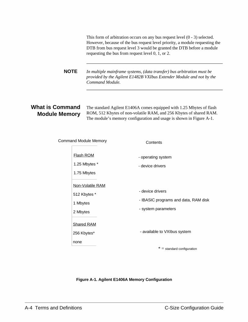
This form of arbitration occurs on any bus request level (0 - 3) selected.However, because of the bus request level priority, a module requesting theDTB from bus request level 3 would be granted the DTB before a modulerequesting the bus from request level 0, 1, or 2.
NOTE In multiple mainframe systems, (data transfer) bus arbitration must beprovided by the Agilent E1482B VXIbus Extender Module and not by theCommand Module.
What is CommandModule Memory
The standard Agilent E1406A comes equipped with 1.25 Mbytes of flashROM, 512 Kbytes of non-volatile RAM, and 256 Kbytes of shared RAM.The module’s memory configuration and usage is shown in Figure A-1.
Non-Volatile RAM
512 Kbytes *
1 Mbytes
2 Mbytes
Shared RAM
256 Kbytes*
none
Flash ROM
1.25 Mbytes *
1.75 Mbytes
* = standard configuration
Command Module Memory
- operating system
- device drivers
- device drivers
- IBASIC programs and data, RAM disk
- system parameters
- available to VXIbus system
Contents
Figure A-1. Agilent E1406A Memory Configuration
A-4 Terms and Definitions C-Size Configuration Guide
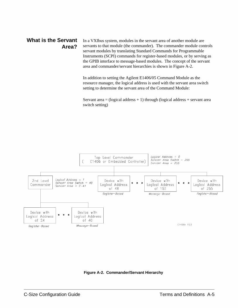
What is the ServantArea?
In a VXIbus system, modules in the servant area of another module areservants to that module (the commander). The commander module controlsservant modules by translating Standard Commands for ProgrammableInstruments (SCPI) commands for register-based modules, or by serving asthe GPIB interface to message-based modules. The concept of the servantarea and commander/servant hierarchies is shown in Figure A-2.
In addition to setting the Agilent E1406/05 Command Module as theresource manager, the logical address is used with the servant area switchsetting to determine the servant area of the Command Module:
Servant area = (logical address + 1) through (logical address + servant areaswitch setting)
Figure A-2. Commander/Servant Hierarchy
C-Size Configuration Guide Terms and Definitions A-5
Servant Area with theCommand Module as
Resource Manager/Slot0 Device
The Command Module should be set so it is the top level commander. TheCommand Module’s logical address setting is combined with its servantarea switch setting to define the Command Module’s servant area.
When the Command Module is the resource manager, its logical address is0. To set the Command Module as the top level commander, its servantarea switch should be set to 255. Then the Command Module’s servant areaincludes all modules with logical addresses from 1 through 255.
The Command Module controls servant modules by translating StandardCommands for Programmable Instruments (SCPI) commands forregister-based modules, or by serving as the GPIB interface tomessage-based modules.
When the Command Module is the resource manager/slot 0 device, thefollowing guidelines apply:
• The Command Module should be the commander for the system’sAgilent Technologies register-based modules. This enables Agilent’sregister-based modules to be programmed with SCPI commands viathe Command Module. The Command Module should also be thecommander for the system’s message-based modules so that theCommand Module will serve as the GPIB interface to thosemodules.
• The Command Module will always be the commander of InstrumentBASIC (IBASIC) whether or not IBASIC is in the CommandModule’s servant area.
• A commander may be a servant to another commander (forming ahierarchical system as shown in Figure A-2). Servants in the servantarea of the "lower-level" commander are controlled by thelower-level commander.
Servant Area with anEmbedded Computer
as ResourceManager/Slot 0 Device
An embedded computer, such as the Agilent E1499A V/382, should be thecommander for the system’s message-based modules (including othercommanders). Modules such as the Agilent E1406/05 Command Moduleshould be the commander for the system’s register-based modules. Thisenables Agilent Technologies’ register-based modules to be programmedwith SCPI commands via the Command Module.
A commander may be a servant to another commander (forming ahierarchical system). Servants in the servant area of the "lower-level"commander are controlled by the lower-level commander.
A-6 Terms and Definitions C-Size Configuration Guide
The embedded computer’s servant area should be set to 255. Thus, if theembedded computer’s logical address is 0 and its servant area setting is 255,the embedded computer will be the top-level commander for all moduleswith logical address between 1 and 255.
When the command module is a servant to an embedded computer, thefollowing guidelines apply:
• For the Command Module to be the commander for a register-basedmodule, the register-based module’s logical address must fall withinthe Command Module’s servant area.
• The Command Module’s logical address plus the CommandModule’s servant area cannot exceed 255. Recommended CommandModule logical addresses are 1, 2, and 3 (0 is reserved for theresource manager, the embedded computer). Therefore, the servantarea should be set based on the logical addresses of theregister-based modules in your system.
What is theCommand Module’s
Primary GPIBAddress?
GPIB is the implementation of ANSI/IEEE Standard 488.1-1978 "IEEEStandard Digital Interface for Programmable Instrumentation". The primaryGPIB address identifies the GPIB port on the Command Module. Thisaddress is combined with the Command Module’s secondary GPIB address(always 00), and with the external computer’s (GPIB) interface select code(typically 7 for HP Computers), to form the Command Module’s completeGPIB address.
The following guidelines will help you set the Command Module’s primaryGPIB address:
• The Command Module has a factory-set GPIB address of 9. If thereis only one Command Module (i.e. only one GPIB port) in yourVXIbus mainframe, then it is not necessary to change this setting. Ifthere are additional Command Modules in a system connected to thesame computer GPIB interface card, each module must have aunique primary GPIB address.
• Valid primary GPIB addresses are 0 through 30.
C-Size Configuration Guide Terms and Definitions A-7
What is the VXI-MXIModule?
With the Agilent E1482B VXI-MXI mainframe extender module, multipleE1401A/E1400B mainframes are integrated into a single VXIbus system.The Agilent E1482 extends the VXI backplane from mainframe tomainframe by converting VXIbus signals to and from the appropriateMXIbus signals, and transmitting them over the MXIbus cables.
For detailed information on VXI-MXI extender module configuration, referto the Agilent E1482B VXI-MXI Bus Extender User’s Manual.
When E1482 VXI-MXI mainframe extender modules are part of yoursystem, the MXI modules must function as the Data Transfer Bus (DTB)timer. This means the bus timer capability of the Command Module orV/382 Controller must be disabled. This is done by setting the ’VME BTODisable’ switch (Command Module) or ’VXIbus Error Timer’ switch(V/382). The bus timer capability of the V743 controller does not have to bedisabled. If you are using an EPC7 as system controller, the EPC7 must be anon-slot 0 device and installed in a slot other than slot 0. This is describedin Procedure 3: Set Up the System for Multiple Mainframes.
What are theVXI-MXI Logical
Address Windows
Each mainframe in a multiple-mainframe VXIbus system is allocated alogical address window. The window is allocated by the resource managerduring the power-on sequence. The size and starting address of the logicaladdress window is determined by the logical addresses of the modules ineach mainframe. When setting the logical addresses of the modules, note thefollowing guidelines.
• The logical address of the VXI-MXI extender module in mainframe1 should be set to 1, 2, 3, ... The logical addresses of the VXI-MXImodules in the other mainframes should be set to values near thestarting address of that mainframe’s logical address window. Forexample, if a mainframe’s logical address window is 128 to 159, setthe VXI-MXI extender module’s address to 129, 130, ... This allowsfor a register-based module to be set to 128, and then be assigned asecondary GPIB address (16) by the Command Module resourcemanager.
• The logical address window size is set to a power of 2 (2, 4, 8,...).The size is the number of logical addresses in the window. Thestarting address is an integer multiple of the size. For example, toallocate a window for 30 logical addresses, the resource managerwill set a window size of 32. Valid starting addresses are 0, 32, 64,96, 128, 160, 192, or 224.
Incidentally, the logical address of the VXI-MXI extender module inthat mainframe should be set to 1, 33, 65, 97, ...
A-8 Terms and Definitions C-Size Configuration Guide
• The logical address window of the root mainframe must be a validwindow (valid starting address and size), and include all of themodules in all of the extender mainframes connected to it.
• No module in one mainframe can be in another mainframe’s logicaladdress window. Therefore, the logical addresses within amainframe should be set such that as small a window as possible isallocated.
• The logical address window of an extender mainframe must includeall modules in that mainframe. The VXI-MXI extender module,however, does not have to be within the window, but must not bewithin the window of another mainframe.
See the Agilent E1482B VXI-MXI Bus Extender User’s Manual foradditional information on determining the Logical Address Window.
What is anInstrumentIdentifier?
Instruments comprised of Agilent Technologies message-based andregister-based modules which are servants to the Agilent E1406/05Command Module are created according to the following rules:
• Each instrument must have one plug-in module assigned as anInstrument Identifier. The Instrument Identifier is the module withits logical address set to a multiple of 8, such as 8, 16, or 24.
• The Instrument Identifier is the lowest logical address in theinstrument. The Command Module maps the Instrument Identifierlogical address to a secondary GPIB address by dividing the logicaladdress by 8. Thus, a logical address of 8 maps to a secondary GPIBaddress of 1; logical address 16 maps to secondary address 2; logicaladdress 24 maps to 3 and so on.
• If an instrument consists of a single module, then its logical addressmust be set to an Instrument Identifier address (multiple of 8).
What are VirtualInstruments?
• An instrument consisting of multiple modules is called a virtualinstrument. The modules of the virtual instrument must be assignedsuccessive logical addresses beginning with the address of theInstrument Identifier. For example, to create a scanning multimetervirtual instrument which consists of a multimeter and twomultiplexers, the logical addresses could be set to:
24 (multimeter)25 (1st multiplexer)26 (2nd multiplexer)
C-Size Configuration Guide Terms and Definitions A-9
Note, however, you cannot combine multiple modules of the same typesuch as multimeters, counters, and function generators into virtualinstruments.
What is the LogicalAddress?
Every device in a VXIbus system has a unique logical address. In AgilentVXIbus systems, the logical address is used to:
• Create instruments
• Establish servant areas
• Derive secondary GPIB addresses that are used to programinstruments from the GPIB
• Determine the base address of the device’s registers in A16 addressspace
• Set the device as the system resource manager (Agilent E1406Command Module)
Setting the LogicalAddress
The following guidelines will help you set logical addresses:
• Notice the factory-set logical address. Most Agilent Technologiesmodules such as DMMs, counters, and function generators have afactory-set address that is an Instrument Identifier (multiple of 8, 8,16, 32, etc).
• Valid logical addresses are 1 through 255. To dynamically configurea module which supports dynamic configuration, its logical addressmust be set to 255. However, if a statically configured module is setto 255, the resource manager will not dynamically configure anymodule.
• If your system consists of statically and dynamically configuredmodules, set the statically configured modules to the "lower"multiples of 8 (e.g. 8, 16, 24). The dynamically configured moduleswill be assigned Instrument Identifier addresses beginning with thelowest available multiple of 8. If all multiples are used, thedynamically configured module is given the first available address.
• A plug-in module with a logical address that is not a multiple of 8,or that is not part of a virtual instrument, is an unassigned module.Such modules must be programmed at the register level, rather thanwith SCPI commands. (A secondary GPIB address can be given toan unassigned module with the Command Module’s User-DefinedCommander/Servant Hierarchy table (see the Agilent E1406 User’sManual).)
A-10 Terms and Definitions C-Size Configuration Guide
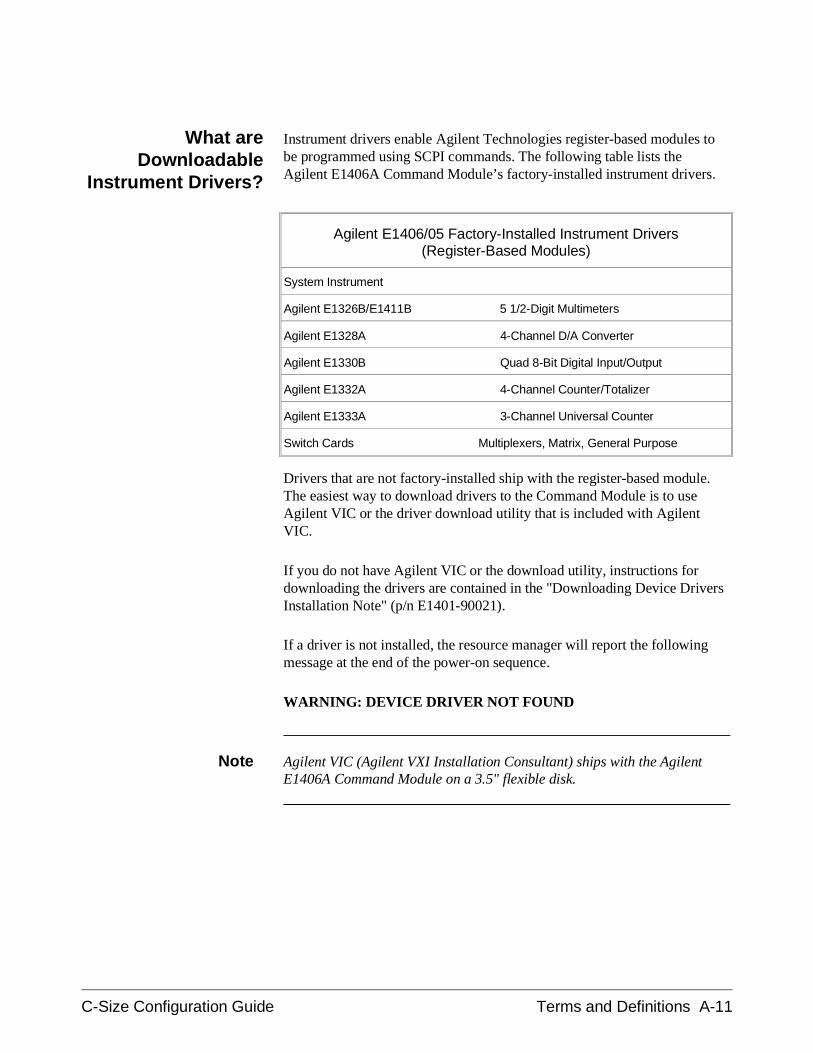
What areDownloadable
Instrument Drivers?
Instrument drivers enable Agilent Technologies register-based modules tobe programmed using SCPI commands. The following table lists theAgilent E1406A Command Module’s factory-installed instrument drivers.
Agilent E1406/05 Factory-Installed Instrument Drivers(Register-Based Modules)
System Instrument
Agilent E1326B/E1411B 5 1/2-Digit Multimeters
Agilent E1328A 4-Channel D/A Converter
Agilent E1330B Quad 8-Bit Digital Input/Output
Agilent E1332A 4-Channel Counter/Totalizer
Agilent E1333A 3-Channel Universal Counter
Switch Cards Multiplexers, Matrix, General Purpose
Drivers that are not factory-installed ship with the register-based module.The easiest way to download drivers to the Command Module is to useAgilent VIC or the driver download utility that is included with AgilentVIC.
If you do not have Agilent VIC or the download utility, instructions fordownloading the drivers are contained in the "Downloading Device DriversInstallation Note" (p/n E1401-90021).
If a driver is not installed, the resource manager will report the followingmessage at the end of the power-on sequence.
WARNING: DEVICE DRIVER NOT FOUND
Note Agilent VIC (Agilent VXI Installation Consultant) ships with the AgilentE1406A Command Module on a 3.5" flexible disk.
C-Size Configuration Guide Terms and Definitions A-11
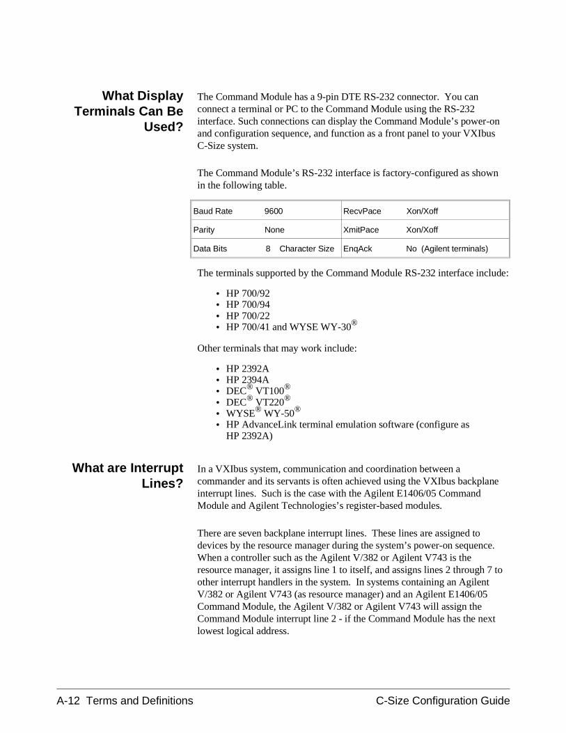
What DisplayTerminals Can Be
Used?
The Command Module has a 9-pin DTE RS-232 connector. You canconnect a terminal or PC to the Command Module using the RS-232interface. Such connections can display the Command Module’s power-onand configuration sequence, and function as a front panel to your VXIbusC-Size system.
The Command Module’s RS-232 interface is factory-configured as shownin the following table.
Baud Rate 9600 RecvPace Xon/Xoff
Parity None XmitPace Xon/Xoff
Data Bits 8 Character Size EnqAck No (Agilent terminals)
The terminals supported by the Command Module RS-232 interface include:
• HP 700/92• HP 700/94• HP 700/22• HP 700/41 and WYSE WY-30®
Other terminals that may work include:
• HP 2392A• HP 2394A• DEC® VT100®
• DEC® VT220®
• WYSE® WY-50®
• HP AdvanceLink terminal emulation software (configure asHP 2392A)
What are InterruptLines?
In a VXIbus system, communication and coordination between acommander and its servants is often achieved using the VXIbus backplaneinterrupt lines. Such is the case with the Agilent E1406/05 CommandModule and Agilent Technologies’s register-based modules.
There are seven backplane interrupt lines. These lines are assigned todevices by the resource manager during the system’s power-on sequence.When a controller such as the Agilent V/382 or Agilent V743 is theresource manager, it assigns line 1 to itself, and assigns lines 2 through 7 toother interrupt handlers in the system. In systems containing an AgilentV/382 or Agilent V743 (as resource manager) and an Agilent E1406/05Command Module, the Agilent V/382 or Agilent V743 will assign theCommand Module interrupt line 2 - if the Command Module has the nextlowest logical address.
A-12 Terms and Definitions C-Size Configuration Guide
Appendix B :Configuration and Start-up Errors
The Agilent E1406 Command Module error messages associated withsystem installation and configuration are shown on the following pages.These messages are displayed if a terminal or printer is connected to theCommand Module’s RS-232 port. If a terminal or printer is not used, themessages can be read from the system instrument error queue, usingSYST:ERR?. An BASIC example using SYST:ERR? is shown below:
DIM Err_msg$[256]REPEAT OUTPUT 70900;"SYST:ERR?" ENTER 70900;Code,Err_msg$ PRINT Code,Err_msg$UNTIL Code=0
NOTE Error codes read from the error queue are preceded by the number 21. Forexample, error code 11 displayed on a monitor would appear as 2111 ifread from the error queue instead.
NOTE If a fatal error has occurred and the system instrument is not started,SYST:ERR? cannot be used to read the error queue.
C-Size Configuration Guide Configuration and Start-up Errors B-1
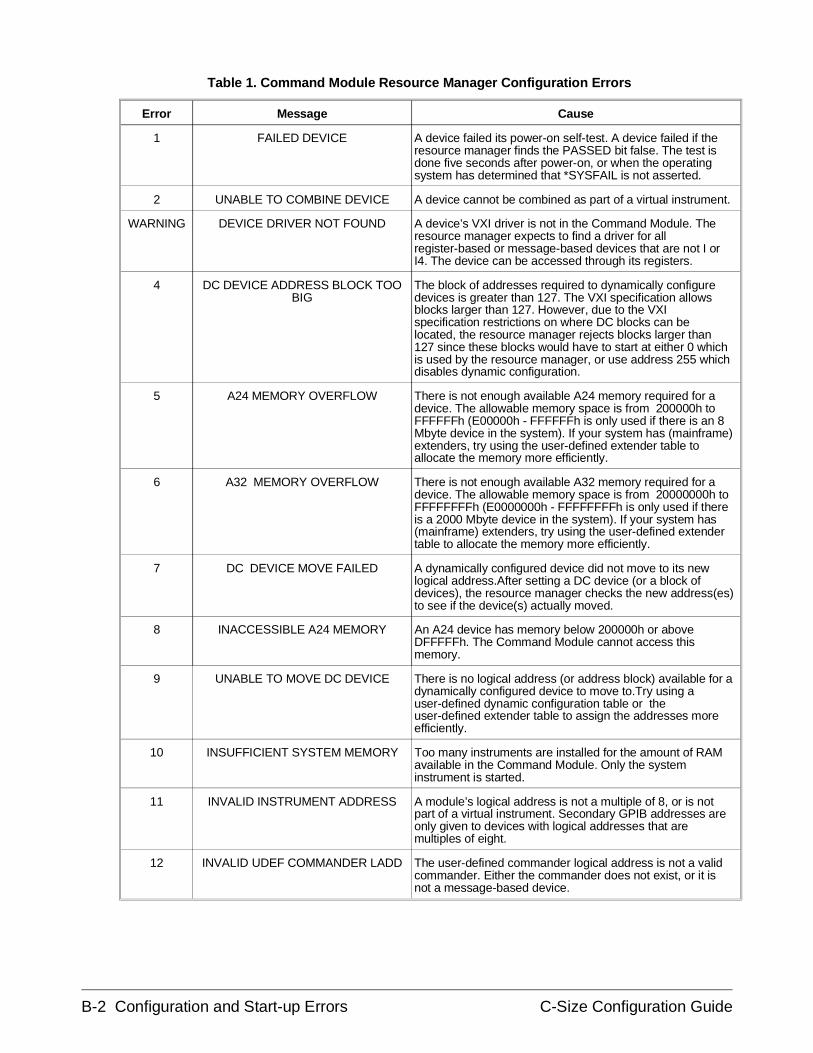
Error Message Cause
1 FAILED DEVICE A device failed its power-on self-test. A device failed if theresource manager finds the PASSED bit false. The test isdone five seconds after power-on, or when the operatingsystem has determined that *SYSFAIL is not asserted.
2 UNABLE TO COMBINE DEVICE A device cannot be combined as part of a virtual instrument.
WARNING DEVICE DRIVER NOT FOUND A device’s VXI driver is not in the Command Module. Theresource manager expects to find a driver for allregister-based or message-based devices that are not I orI4. The device can be accessed through its registers.
4 DC DEVICE ADDRESS BLOCK TOOBIG
The block of addresses required to dynamically configuredevices is greater than 127. The VXI specification allowsblocks larger than 127. However, due to the VXIspecification restrictions on where DC blocks can belocated, the resource manager rejects blocks larger than127 since these blocks would have to start at either 0 whichis used by the resource manager, or use address 255 whichdisables dynamic configuration.
5 A24 MEMORY OVERFLOW There is not enough available A24 memory required for adevice. The allowable memory space is from 200000h toFFFFFFh (E00000h - FFFFFFh is only used if there is an 8Mbyte device in the system). If your system has (mainframe)extenders, try using the user-defined extender table toallocate the memory more efficiently.
6 A32 MEMORY OVERFLOW There is not enough available A32 memory required for adevice. The allowable memory space is from 20000000h toFFFFFFFFh (E0000000h - FFFFFFFFh is only used if thereis a 2000 Mbyte device in the system). If your system has(mainframe) extenders, try using the user-defined extendertable to allocate the memory more efficiently.
7 DC DEVICE MOVE FAILED A dynamically configured device did not move to its newlogical address.After setting a DC device (or a block ofdevices), the resource manager checks the new address(es)to see if the device(s) actually moved.
8 INACCESSIBLE A24 MEMORY An A24 device has memory below 200000h or aboveDFFFFFh. The Command Module cannot access thismemory.
9 UNABLE TO MOVE DC DEVICE There is no logical address (or address block) available for adynamically configured device to move to.Try using auser-defined dynamic configuration table or theuser-defined extender table to assign the addresses moreefficiently.
10 INSUFFICIENT SYSTEM MEMORY Too many instruments are installed for the amount of RAMavailable in the Command Module. Only the systeminstrument is started.
11 INVALID INSTRUMENT ADDRESS A module’s logical address is not a multiple of 8, or is notpart of a virtual instrument. Secondary GPIB addresses areonly given to devices with logical addresses that aremultiples of eight.
12 INVALID UDEF COMMANDER LADD The user-defined commander logical address is not a validcommander. Either the commander does not exist, or it isnot a message-based device.
Table 1. Command Module Resource Manager Configuration Errors
B-2 Configuration and Start-up Errors C-Size Configuration Guide
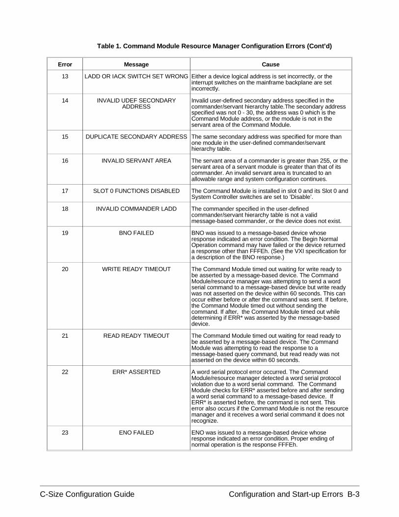
Error Message Cause
13 LADD OR IACK SWITCH SET WRONG Either a device logical address is set incorrectly, or theinterrupt switches on the mainframe backplane are setincorrectly.
14 INVALID UDEF SECONDARYADDRESS
Invalid user-defined secondary address specified in thecommander/servant hierarchy table.The secondary addressspecified was not 0 - 30, the address was 0 which is theCommand Module address, or the module is not in theservant area of the Command Module.
15 DUPLICATE SECONDARY ADDRESS The same secondary address was specified for more thanone module in the user-defined commander/servanthierarchy table.
16 INVALID SERVANT AREA The servant area of a commander is greater than 255, or theservant area of a servant module is greater than that of itscommander. An invalid servant area is truncated to anallowable range and system configuration continues.
17 SLOT 0 FUNCTIONS DISABLED The Command Module is installed in slot 0 and its Slot 0 andSystem Controller switches are set to ’Disable’.
18 INVALID COMMANDER LADD The commander specified in the user-definedcommander/servant hierarchy table is not a validmessage-based commander, or the device does not exist.
19 BNO FAILED BNO was issued to a message-based device whoseresponse indicated an error condition. The Begin NormalOperation command may have failed or the device returneda response other than FFFEh. (See the VXI specification fora description of the BNO response.)
20 WRITE READY TIMEOUT The Command Module timed out waiting for write ready tobe asserted by a message-based device. The CommandModule/resource manager was attempting to send a wordserial command to a message-based device but write readywas not asserted on the device within 60 seconds. This canoccur either before or after the command was sent. If before,the Command Module timed out without sending thecommand. If after, the Command Module timed out whiledetermining if ERR* was asserted by the message-baseddevice.
21 READ READY TIMEOUT The Command Module timed out waiting for read ready tobe asserted by a message-based device. The CommandModule was attempting to read the response to amessage-based query command, but read ready was notasserted on the device within 60 seconds.
22 ERR* ASSERTED A word serial protocol error occurred. The CommandModule/resource manager detected a word serial protocolviolation due to a word serial command. The CommandModule checks for ERR* asserted before and after sendinga word serial command to a message-based device. IfERR* is asserted before, the command is not sent. Thiserror also occurs if the Command Module is not the resourcemanager and it receives a word serial command it does notrecognize.
23 ENO FAILED ENO was issued to a message-based device whoseresponse indicated an error condition. Proper ending ofnormal operation is the response FFFEh.
Table 1. Command Module Resource Manager Configuration Errors (Cont’d)
C-Size Configuration Guide Configuration and Start-up Errors B-3
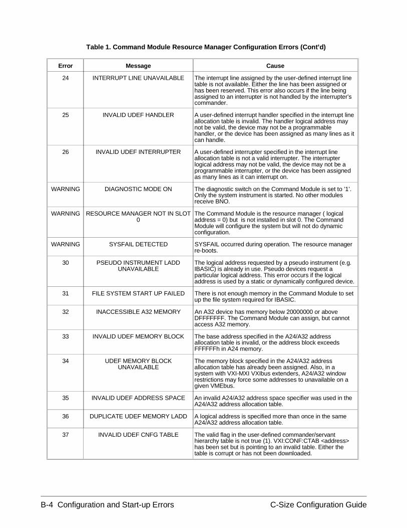
Error Message Cause
24 INTERRUPT LINE UNAVAILABLE The interrupt line assigned by the user-defined interrupt linetable is not available. Either the line has been assigned orhas been reserved. This error also occurs if the line beingassigned to an interrupter is not handled by the interrupter’scommander.
25 INVALID UDEF HANDLER A user-defined interrupt handler specified in the interrupt lineallocation table is invalid. The handler logical address maynot be valid, the device may not be a programmablehandler, or the device has been assigned as many lines as itcan handle.
26 INVALID UDEF INTERRUPTER A user-defined interrupter specified in the interrupt lineallocation table is not a valid interrupter. The interrupterlogical address may not be valid, the device may not be aprogrammable interrupter, or the device has been assignedas many lines as it can interrupt on.
WARNING DIAGNOSTIC MODE ON The diagnostic switch on the Command Module is set to ’1’.Only the system instrument is started. No other modulesreceive BNO.
WARNING RESOURCE MANAGER NOT IN SLOT0
The Command Module is the resource manager ( logicaladdress = 0) but is not installed in slot 0. The CommandModule will configure the system but will not do dynamicconfiguration.
WARNING SYSFAIL DETECTED SYSFAIL occurred during operation. The resource managerre-boots.
30 PSEUDO INSTRUMENT LADDUNAVAILABLE
The logical address requested by a pseudo instrument (e.g.IBASIC) is already in use. Pseudo devices request aparticular logical address. This error occurs if the logicaladdress is used by a static or dynamically configured device.
31 FILE SYSTEM START UP FAILED There is not enough memory in the Command Module to setup the file system required for IBASIC.
32 INACCESSIBLE A32 MEMORY An A32 device has memory below 20000000 or aboveDFFFFFFF. The Command Module can assign, but cannotaccess A32 memory.
33 INVALID UDEF MEMORY BLOCK The base address specified in the A24/A32 addressallocation table is invalid, or the address block exceedsFFFFFFh in A24 memory.
34 UDEF MEMORY BLOCKUNAVAILABLE
The memory block specified in the A24/A32 addressallocation table has already been assigned. Also, in asystem with VXI-MXI VXIbus extenders, A24/A32 windowrestrictions may force some addresses to unavailable on agiven VMEbus.
35 INVALID UDEF ADDRESS SPACE An invalid A24/A32 address space specifier was used in theA24/A32 address allocation table.
36 DUPLICATE UDEF MEMORY LADD A logical address is specified more than once in the sameA24/A32 address allocation table.
37 INVALID UDEF CNFG TABLE The valid flag in the user-defined commander/servanthierarchy table is not true (1). VXI:CONF:CTAB <address>has been set but is pointing to an invalid table. Either thetable is corrupt or has not been downloaded.
Table 1. Command Module Resource Manager Configuration Errors (Cont’d)
B-4 Configuration and Start-up Errors C-Size Configuration Guide
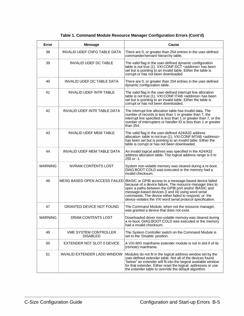
Error Message Cause
38 INVALID UDEF CNFG TABLE DATA There are 0, or greater than 254 entries in the user-definedcommander/servant hierarchy table.
39 INVALID UDEF DC TABLE The valid flag in the user-defined dynamic configurationtable is not true (1). VXI:CONF:DCT <address> has beenset but is pointing to an invalid table. Either the table iscorrupt or has not been downloaded.
40 INVALID UDEF DC TABLE DATA There are 0, or greater than 254 entries in the user-defineddynamic configuration table.
41 INVALID UDEF INTR TABLE The valid flag in the user-defined interrupt line allocationtable is not true (1). VXI:CONF:ITAB <address> has beenset but is pointing to an invalid table. Either the table iscorrupt or has not been downloaded.
42 INVALID UDEF INTR TABLE DATA The interrupt line allocation table has invalid data. Thenumber of records is less than 1 or greater than 7, theinterrupt line specified is less than 1 or greater than 7, or thenumber of interrupters or handler ID is less than 1 or greaterthan 254.
43 INVALID UDEF MEM TABLE The valid flag in the user-defined A24/A32 addressallocation table is not true (1). VXI:CONF:MTAB <address>has been set but is pointing to an invalid table. Either thetable is corrupt or has not been downloaded.
44 INVALID UDEF MEM TABLE DATA An invalid logical address was specified in the A24/A32address allocation table. The logical address range is 0 to255 or -1.
WARNING NVRAM CONTENTS LOST System non-volatile memory was cleared during a re-boot.DIAG:BOOT:COLD was executed or the memory had ainvalid checksum.
46 MESG BASED OPEN ACCESS FAILED IBASIC or GPIB access to a message-based device failedbecause of a device failure. The resource manager tries toopen a paths between the GPIB port and/or IBASIC andmessage-based devices (I and I4) using word serialcommands. The device either failed to respond, or thedevice violates the VXI word serial protocol specification.
47 GRANTED DEVICE NOT FOUND The Command Module, when not the resource manager,was granted a device that does not exist.
WARNING DRAM CONTENTS LOST Downloaded driver non-volatile memory was cleared duringa re-boot. DIAG:BOOT:COLD was executed or the memoryhad a invalid checksum.
49 VME SYSTEM CONTROLLERDISABLED
The System Controller switch on the Command Module isset to the ’Disable’ position.
50 EXTENDER NOT SLOT 0 DEVICE A VXI-MXI mainframe extender module is not in slot 0 of its(remote) mainframe.
51 INVALID EXTENDER LADD WINDOW Modules do not fit in the logical address window set by theuser-defined extender table. Not all of the devices found"below" an extender will fit into the largest available windowfor that extender. Either reset the logical addresses or usethe extender table to override the default algorithm.
Table 1. Command Module Resource Manager Configuration Errors (Cont’d)
C-Size Configuration Guide Configuration and Start-up Errors B-5
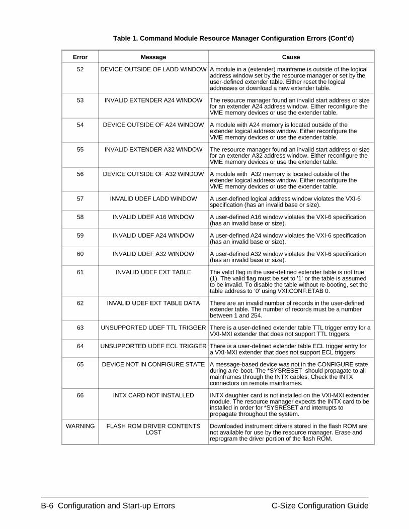
Error Message Cause
52 DEVICE OUTSIDE OF LADD WINDOW A module in a (extender) mainframe is outside of the logicaladdress window set by the resource manager or set by theuser-defined extender table. Either reset the logicaladdresses or download a new extender table.
53 INVALID EXTENDER A24 WINDOW The resource manager found an invalid start address or sizefor an extender A24 address window. Either reconfigure theVME memory devices or use the extender table.
54 DEVICE OUTSIDE OF A24 WINDOW A module with A24 memory is located outside of theextender logical address window. Either reconfigure theVME memory devices or use the extender table.
55 INVALID EXTENDER A32 WINDOW The resource manager found an invalid start address or sizefor an extender A32 address window. Either reconfigure theVME memory devices or use the extender table.
56 DEVICE OUTSIDE OF A32 WINDOW A module with A32 memory is located outside of theextender logical address window. Either reconfigure theVME memory devices or use the extender table.
57 INVALID UDEF LADD WINDOW A user-defined logical address window violates the VXI-6specification (has an invalid base or size).
58 INVALID UDEF A16 WINDOW A user-defined A16 window violates the VXI-6 specification(has an invalid base or size).
59 INVALID UDEF A24 WINDOW A user-defined A24 window violates the VXI-6 specification(has an invalid base or size).
60 INVALID UDEF A32 WINDOW A user-defined A32 window violates the VXI-6 specification(has an invalid base or size).
61 INVALID UDEF EXT TABLE The valid flag in the user-defined extender table is not true(1). The valid flag must be set to ’1’ or the table is assumedto be invalid. To disable the table without re-booting, set thetable address to ’0’ using VXI:CONF:ETAB 0.
62 INVALID UDEF EXT TABLE DATA There are an invalid number of records in the user-definedextender table. The number of records must be a numberbetween 1 and 254.
63 UNSUPPORTED UDEF TTL TRIGGER There is a user-defined extender table TTL trigger entry for aVXI-MXI extender that does not support TTL triggers.
64 UNSUPPORTED UDEF ECL TRIGGER There is a user-defined extender table ECL trigger entry fora VXI-MXI extender that does not support ECL triggers.
65 DEVICE NOT IN CONFIGURE STATE A message-based device was not in the CONFIGURE stateduring a re-boot. The *SYSRESET should propagate to allmainframes through the INTX cables. Check the INTXconnectors on remote mainframes.
66 INTX CARD NOT INSTALLED INTX daughter card is not installed on the VXI-MXI extendermodule. The resource manager expects the INTX card to beinstalled in order for *SYSRESET and interrupts topropagate throughout the system.
WARNING FLASH ROM DRIVER CONTENTSLOST
Downloaded instrument drivers stored in the flash ROM arenot available for use by the resource manager. Erase andreprogram the driver portion of the flash ROM.
Table 1. Command Module Resource Manager Configuration Errors (Cont’d)
B-6 Configuration and Start-up Errors C-Size Configuration Guide
Checking forInstrument Errors
The following BASIC program is a method of checking for errors as youprogram the instruments (plug-in modules) in your VXIbus system. Theprogram monitors the instrument’s Standard Event Status Register for errorconditions. If no errors occur, the instrument functions as programmed. Iferrors are detected, the instrument interrupts the controller. The controllerreads the error codes and messages from the instrument’s error queue anddisplays them. In this program, the instrument (multimeter) at secondaryGPIB address 03 (logical address 24) is monitored. The controllercommands used are for an HP Series 300 controller (external or anembedded controller) running the BASIC language.
NOTE If an RS-232 display terminal is used, typing:
SYST:ERR?
at the VOLTMTR_24: prompt reads and displays the error messages fromthe multimeter’s error queue.
C-Size Configuration Guide Configuration and Start-up Errors B-7
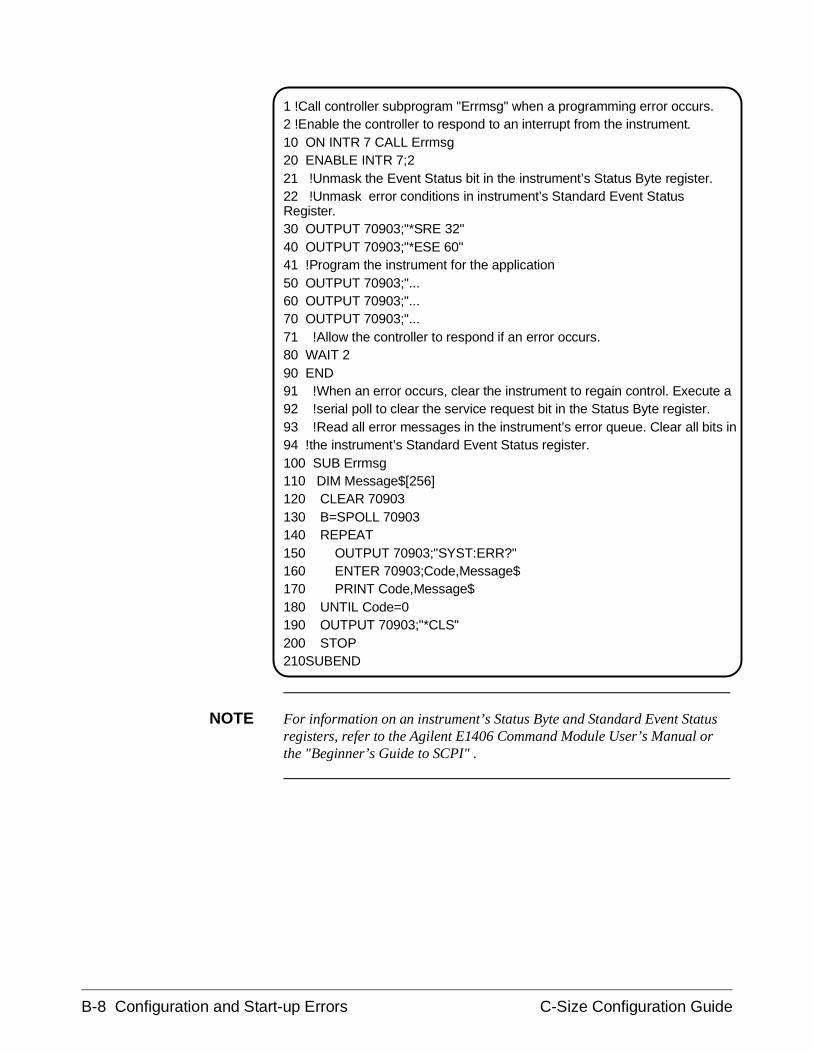
1 !Call controller subprogram "Errmsg" when a programming error occurs.2 !Enable the controller to respond to an interrupt from the instrument.10 ON INTR 7 CALL Errmsg20 ENABLE INTR 7;221 !Unmask the Event Status bit in the instrument’s Status Byte register.22 !Unmask error conditions in instrument’s Standard Event StatusRegister.30 OUTPUT 70903;"*SRE 32"40 OUTPUT 70903;"*ESE 60"41 !Program the instrument for the application50 OUTPUT 70903;"...60 OUTPUT 70903;"...70 OUTPUT 70903;"...71 !Allow the controller to respond if an error occurs.80 WAIT 290 END91 !When an error occurs, clear the instrument to regain control. Execute a92 !serial poll to clear the service request bit in the Status Byte register.93 !Read all error messages in the instrument’s error queue. Clear all bits in94 !the instrument’s Standard Event Status register.100 SUB Errmsg110 DIM Message$[256]120 CLEAR 70903130 B=SPOLL 70903140 REPEAT150 OUTPUT 70903;"SYST:ERR?"160 ENTER 70903;Code,Message$170 PRINT Code,Message$180 UNTIL Code=0190 OUTPUT 70903;"*CLS"200 STOP210SUBEND
NOTE For information on an instrument’s Status Byte and Standard Event Statusregisters, refer to the Agilent E1406 Command Module User’s Manual orthe "Beginner’s Guide to SCPI" .
B-8 Configuration and Start-up Errors C-Size Configuration Guide
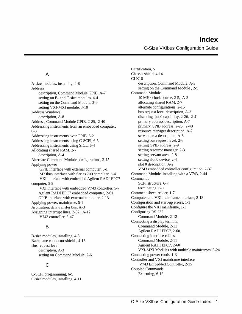
IndexC-Size VXIbus Configuration Guide
A
A-size modules, installing, 4-8Address
description, Command Module GPIB, A-7setting on B- and C-size modules, 4-4setting on the Command Module, 2-9setting VXI-MXI module, 3-10
Address Windowsdescription, A-8
Address, Command Module GPIB, 2-25, 2-40Addressing instruments from an embedded computer,6-3Addressing instruments over GPIB, 6-2Addressing instruments using C-SCPI, 6-5Addressing instruments using SICL, 6-4Allocating shared RAM, 2-7
description, A-4Alternate Command Module configurations, 2-15Applying power
GPIB interface with external computer, 5-1 MXIbus interface with Series 700 computer, 5-4 VXI interface with embedded Agilent RADI-EPC7
computer, 5-9 VXI interface with embedded V743 controller, 5-7Agilent RADI EPC7 embedded computer, 2-61GPIB interface with external computer, 2-13
Applying power, mainframe, 5-1Arbitration, data transfer bus, A-3Assigning interrupt lines, 2-32, A-12
V743 controller, 2-47
B
B-size modules, installing, 4-8Backplane connector shields, 4-15Bus request level
description, A-3setting on Command Module, 2-6
C
C-SCPI programming, 6-5C-size modules, installing, 4-11
Certification, 5Chassis shield, 4-14CLK10
description, Command Module, A-3setting on the Command Module , 2-5
Command Module10 MHz clock source, 2-5, A-3allocating shared RAM, 2-7alternate configurations, 2-15bus request level description, A-3disabling slot 0 capability, 2-26, 2-41primary address description, A-7primary GPIB address, 2-25, 2-40resource manager description, A-2servant area description, A-5setting bus request level, 2-6setting GPIB address, 2-9setting resource manager, 2-3setting servant area , 2-8setting slot 0 device, 2-4slot 0 description, A-2V743 embedded controller configuration, 2-37
Command Module, installing with a V743, 2-44Commands
SCPI structure, 6-7terminating, 6-8
Comment sheet, reader, 1-7Computer and VXI mainframe interface, 2-18Configuration and start-up errors, 1-1Configure the VXI mainframe, 1-1Configuring RS-232
Command Module, 2-12Connecting a display terminal
Command Module, 2-11Agilent RADI EPC7, 2-60
Connecting interface cablesCommand Module, 2-11Agilent RADI EPC7, 2-60VXI-MXI Modules with multiple mainframes, 3-24
Connecting power cords, 1-3Controller and VXI mainframe interface
V743 Embedded Controller, 2-35Coupled Commands
Executing, 6-12
C-Size VXIbus Configuration Guide Index 1

D
Data Transfer Bus Arbitration, A-3Debugging Programs, 6-6Disable VME BTO Timeout
Command Module, 3-20RadiSys EPC-7, 3-21
Disabling the Command Module’s VMEbus Time Outcapability, 2-26Display Terminals
connecting Command Module, 2-11connecting EPC7, 2-60description, A-12
Documentation history, 6Downloading instrument drivers
description, A-11procedure, 4-3
Drivers, downloading, 4-3, A-11
E
Embedded computer programming, 6-3Enabling shared memory, V743 controller, 2-46EPC7
installing, 2-52non-slot 0, 2-51Slot 0 Device, 2-50
Error messagesconfiguration and start-up, 1-1
Errorschecking for, 1-7
Example programschecking for instrument errors, 1-7
Executing Coupled Commands, 6-12
F
Faceplate panels, installing, 4-16
G
GPIB addressdescription, A-7setting, 2-25, 2-40setting on the Command Module, 2-9
GPIB cables, connectingCommand Module, 2-11
GPIB programming, 6-2
H
How to Create an Instrumentlogical address description, A-10setting the logical address, 4-4
I
Installation backplane connector shields, 4-15A-size modules, 4-8B-size modules, 4-8C-size modules, 4-11chassis shield, 4-14faceplate panels, 4-16RADI EPC7, 2-52RADI EXM Modules, 2-54VXI-MXI Modules, 3-22
Installing the Command Module, 2-44Installing the V743 controller, 2-42Instrument drivers, downloading, 4-3Instrument errors, checking for, 1-7Instrument identifier
description, A-9Instrument language, SCPI, 6-7Instruments
description on creating, A-9Interface cables
connecting Command Module, 2-11connecting Agilent RADI EPC7, 2-60connecting VXI-MXI Modules, 3-24
Interrupt linesdescription, A-12
Interrupt lines, assigned by V743 controller, 2-47Interrupt lines, assigning, 2-32
L
Line feed, terminating commands, 6-8Logical address
V743 and servant area, 2-37description of setting, A-10description, Command Module, A-2description, plug-in module, A-10setting on Command Module, 2-3setting plug-in module, 4-4
Logical address and servant area guidelinesV743 controller, 2-38
Logical address windowsdescription of setting, A-8
Logical addresses, verifying, 6-8
2 C-Size VXIbus Configuration Guide Index
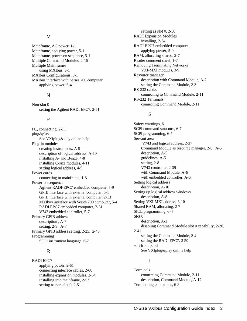
M
Mainframe, AC power, 1-1Mainframe, applying power, 5-1Mainframe, power-on sequence, 5-1Multiple Command Modules, 2-15Multiple Mainframes
using MXIbus, 3-1MXIbus Configurations, 3-1MXIbus interface with Series 700 computer
applying power, 5-4
N
Non-slot 0setting the Agilent RADI EPC7, 2-51
P
PC, connecting, 2-11plug&play
See VXIplug&play online helpPlug-in modules
creating instruments, A-9description of logical address, A-10installing A- and B-size, 4-8installing C-size modules, 4-11setting logical address, 4-5
Power cordsconnecting to mainframe, 1-3
Power-on sequenceAgilent RADI-EPC7 embedded computer, 5-9GPIB interface with external computer, 5-1GPIB interface with external computer, 2-13MXIbus interface with Series 700 computer, 5-4RADI EPC7 embedded computer, 2-61V743 embedded controller, 5-7
Primary GPIB addressdescription , A-7setting, 2-9, A-7
Primary GPIB address setting, 2-25, 2-40Programming
SCPI instrument language, 6-7
R
RADI EPC7applying power, 2-61connecting interface cables, 2-60installing expansion modules, 2-54installing into mainframe, 2-52setting as non-slot 0, 2-51
setting as slot 0, 2-50RADI Expansion Modules
installing, 2-54RADI-EPC7 embedded computer
applying power, 5-9RAM, allocating shared, 2-7Reader comment sheet, 1-7Removing Terminating Networks
VXI-MXI modules, 3-9Resource manager
description with Command Module, A-2setting the Command Module, 2-3
RS-232 cablesconnecting to Command Module, 2-11
RS-232 Terminalsconnecting Command Module, 2-11
S
Safety warnings, 6SCPI command structure, 6-7SCPI programming, 6-7Servant area
V743 and logical address, 2-37Command Module as resource manager, 2-8, A-5description, A-5guidelines, A-5setting, 2-8V743 controller, 2-39with Command Module, A-6with embedded controller, A-6
Setting logical addressdescription, A-10
Setting up logical address windowsdescription, A-8
Setting VXI-MXI address, 3-10Shared RAM, allocating, 2-7SICL programming, 6-4Slot 0
description, A-2disabling Command Module slot 0 capability, 2-26,
2-41setting the Command Module, 2-4setting the RADI EPC7, 2-50
soft front panelSee VXIplug&play online help
T
Terminalsconnecting Command Module, 2-11description, Command Module, A-12
Terminating commands, 6-8
C-Size VXIbus Configuration Guide Index 3
Terminating Networksremoving, VXI-MXI modules, 3-9
Turning on the mainframe, 5-1
V
V743 Controller and Command Module configuration, 2-37 enabling shared memory, 2-46 installing, 2-42Command Module servant area guidelines, 2-39logical address and servant area guidelines, 2-38
V743 embedded controllerapplying power, 5-7
V743 logical address and servant area, 2-37Verifying communication, 6-2Verifying system logical addresses, 6-8Virtual Instruments
create, 4-4description, A-9
VME BTO Timeoutdisabling, Command Module, 3-20disabling, EPC-7, 3-21
VMEbus Time Out, disabling on the CommandModule, 2-26VXI mainframe, computer interface and, 2-18VXI mainframe, V743 embedded controller and, 2-35VXI-MXI Configurations, 3-1VXI-MXI module
2-frame, 3-182-frame, Command Module, 3-122-frame, EPC-7 embedded controller, 3-162-frame, external controller, 3-143-frame, 3-193-frame, Command Module, 3-133-frame, EPC-7 embedded controller, 3-173-frame, external controller, 3-15removing terminating networks, 3-9setting address, 3-10
VXI-MXI systemlogical address windows, A-8
VXI-MXI with multiple mainframes, 3-1VXIplug&play example programs
See VXIplug&play online helpVXIplug&play function reference
See VXIplug&play online helpVXIplug&play programming
See VXIplug&play online helpVXIplug&play Soft Front Panel
See VXIplug&play online help
W
WARNINGS, 6Warranty, 5What are address windows?, A-8What are interrupt lines?, A-12What are virtual instruments?, A-9What is a downloadable driver?, A-11What is an instrument identifier?, A-9What is bus request level?, A-3What is CLK10?, A-3What is primary GPIB address?, A-7What is Resource Manager?, A-2What is servant area?, A-5What is the slot 0 device?, A-2
4 C-Size VXIbus Configuration Guide Index