Embed Size (px)
Citation preview
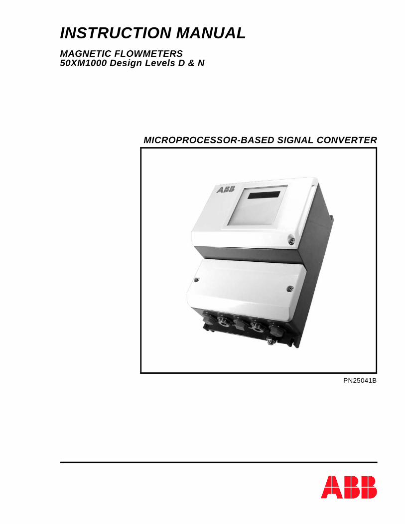
INSTRUCTION MANUALMAGNETIC FLOWMETERS50XM1000 Design Levels D & N
MICROPROCESSOR-BASED SIGNAL CONVERTER
PN25041B
The following are registered trademarks of ABB Inc.: MAG-X®
MICRO-DCI
The following is a registered trademark of Littelfuse Tracor Inc: LITTELFUSE®
The following is a registered trademark of the HART Communications Foundation: HART®
WARNING notices as used in this manual apply to hazards or unsafe practices which could result in personal in-jury or death.
CAUTION notices apply to hazards or unsafe practices which could result in property damage.
NOTES highlight procedures and contain information which assist the operator in understanding the informationcontained in this manual.
All software, including design, appearance, algorithms and source codes, is owned and copyrighted byABB Inc. or its suppliers.
WARNINGINSTRUCTION MANUALSDo not install, maintain or operate this equipment without reading, understanding and following theproper ABB Inc. instructions and manuals, otherwise injury or damage may result.
POSSIBLE PROCESS UPSETSOperation & maintenance must be performed only by qualified personnel and only after securingequipment controlled by this product. Adjusting or removing this product while it is in the system mayupset the process being controlled. Some process upsets may cause injury or damage.
NOTICE
The information contained in this document is subject to change without notice. ABB Inc. reserves theright to make minor changes to this publication, such as company name & logos as well as other minorcorrections, without necessarily changing the publication number.
ABB Inc., its affiliates, employees, and agents, and the authors of and contributors to this publicationspecifically disclaim all liabilities and warranties, express and implied (including warranties ofmerchantability and fitness for a particular purpose), for the accuracy, currency, completeness, and/orreliability of the information contained herein and/or for the fitness for any particular use and/or for theperformance of any material and/or equipment selected in whole or part with the user of/or in relianceupon information contained herein. Selection of materials and/or equipment is at the sole risk of theuser of this publication.
This document contains proprietary information of ABB Inc. and is issued in strict confidence. Its use,or reproduction for use, for the reverse engineering, development or manufacture of hardware orsoftware described herein is prohibited. No part of this document may be photocopied or reproducedwithout the prior written consent of ABB Inc.
Copyright 2005 ABB Inc. [January, 2005]

Model 50XM1000Design Levels D & NMagmeter Signal Converter
ADDENDUM TO MAGNETIC FLOWMETER50XM1000D/N INSTRUCTION MANUAL
The purpose of this addendum is to revise the Model Number Breakdownsection of the 50XM1000D/N Magnetic Flowmeter Signal Converter
Instruction Manual
The information on the following pages supersedes the existing information in Section 1.2 (pages 1-6 & 1-7)of the Model 50XM1000 Design Levels D & N Instruction Manual (PN25041B). Only the "Certifications"section of the Model Number Breakdown on Page 1-6 has been revised, all other model number informationis identical to that shown in the instruction manual.
Copyright 2002 ABB Inc. [September, 2002] PN25063
ADDENDUM
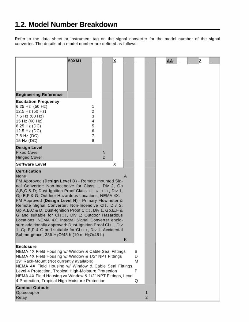
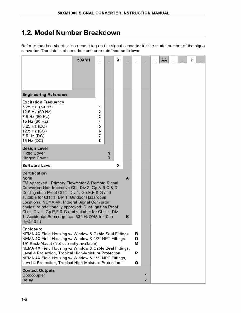
1.2. Model Number Breakdown
Refer to the data sheet or instrument tag on the signal converter for the model number of the signalconverter. The details of a model number are defined as follows:
50XM1 _ _ X _ _ _ _ AA _ _ 2 _
Engineering Reference
Excitation Frequency6.25 Hz (50 Hz)12.5 Hz (50 Hz)7.5 Hz (60 Hz)15 Hz (60 Hz)6.25 Hz (DC)12.5 Hz (DC)7.5 Hz (DC)15 Hz (DC)
12345678
Design LevelFixed CoverHinged Cover
ND
Software Level X
CertificationNoneFM Approved (Design Level D) - Remote mounted Sig-nal Converter: Non-Incendive for Class I, Div 2, GpA,B,C & D; Dust-Ignition Proof Class II & III, Div 1,Gp E,F & G; Outdoor Hazardous Locations, NEMA 4X. FM Approved (Design Level N) - Primary Flowmeter &Remote Signal Converter: Non-Incendive ClI, Div 2,Gp.A,B,C & D, Dust-Ignition Proof ClII, Div 1, Gp.E,F &G and suitable for ClIII, Div 1; Outdoor HazardousLocations, NEMA 4X. Integral Signal Converter enclo-sure additionally approved: Dust-Ignition Proof ClII, Div1, Gp.E,F & G and suitable for ClIII, Div 1; AccidentalSubmergence, 33ft H2O/48 h (10 m H2O/48 h)
A
K
EnclosureNEMA 4X Field Housing w/ Window & Cable Seal FittingsNEMA 4X Field Housing w/ Window & 1/2" NPT Fittings19" Rack-Mount (Not currently available)NEMA 4X Field Housing w/ Window & Cable Seal Fittings,Level 4 Protection, Tropical High-Moisture ProtectionNEMA 4X Field Housing w/ Window & 1/2" NPT Fittings, Level4 Protection, Tropical High-Moisture Protection
BDM
P
Q
Contact OutputsOptocouplerRelay
12
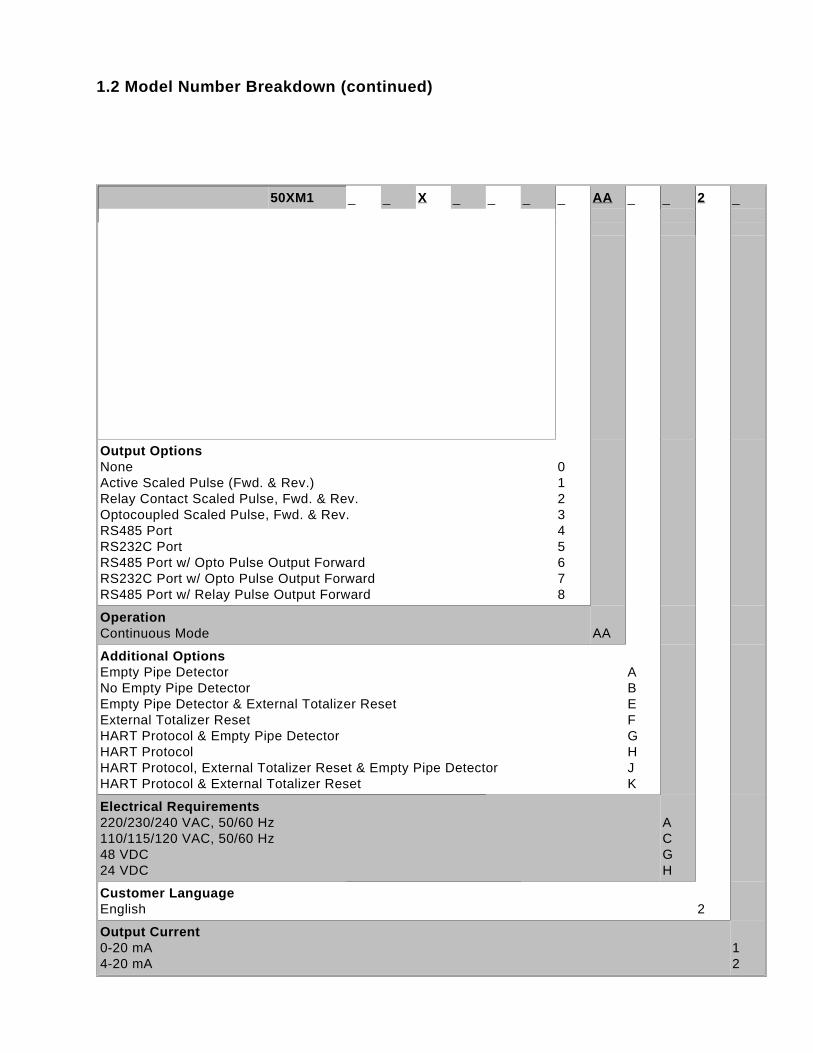
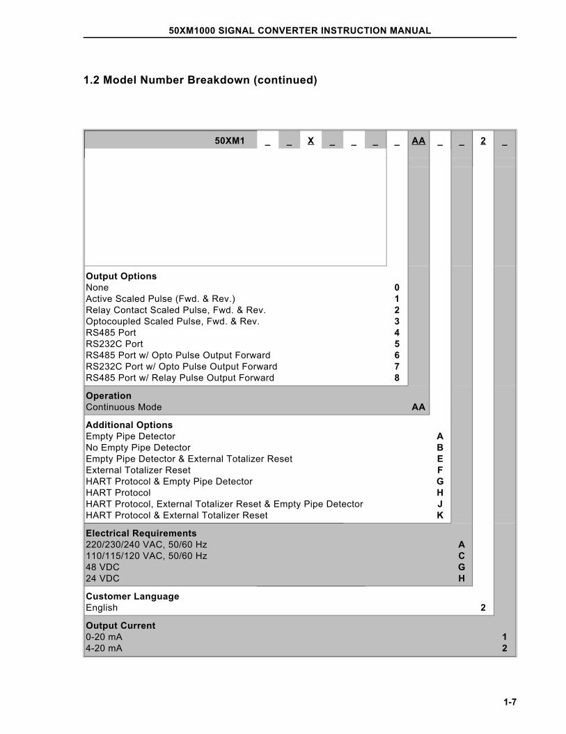
1.2 Model Number Breakdown (continued)
50XM1 _ _ X _ _ _ _ AA _ _ 2 _
Output OptionsNoneActive Scaled Pulse (Fwd. & Rev.)Relay Contact Scaled Pulse, Fwd. & Rev.Optocoupled Scaled Pulse, Fwd. & Rev.RS485 PortRS232C PortRS485 Port w/ Opto Pulse Output ForwardRS232C Port w/ Opto Pulse Output ForwardRS485 Port w/ Relay Pulse Output Forward
012345678
OperationContinuous Mode AA
Additional OptionsEmpty Pipe DetectorNo Empty Pipe DetectorEmpty Pipe Detector & External Totalizer ResetExternal Totalizer ResetHART Protocol & Empty Pipe Detector HART ProtocolHART Protocol, External Totalizer Reset & Empty Pipe DetectorHART Protocol & External Totalizer Reset
ABEFGHJK
Electrical Requirements220/230/240 VAC, 50/60 Hz110/115/120 VAC, 50/60 Hz48 VDC24 VDC
ACGH
Customer LanguageEnglish 2
Output Current0-20 mA4-20 mA
12
Table of ContentsSAFETY SUMMARY . . . . . . . . . . . . . . . . . . . . . . . . . . . . . . . . . . . . . . . . . . . . . . . . . . . . . I
READ FIRST . . . . . . . . . . . . . . . . . . . . . . . . . . . . . . . . . . . . . . . . . . . . . . . . . . . . . . . . . V
1.0 INTRODUCTION . . . . . . . . . . . . . . . . . . . . . . . . . . . . . . . . . . . . . . . . . . . . . . . . . . 1-11.1 General Description . . . . . . . . . . . . . . . . . . . . . . . . . . . . . . . . . . . . . . . . . . . . . . . . . . . . . . . . . . . . . . 1-11.2. Model Number Breakdown . . . . . . . . . . . . . . . . . . . . . . . . . . . . . . . . . . . . . . . . . . . . . . . . . . . . . . . . 1-61.3. Specifications. . . . . . . . . . . . . . . . . . . . . . . . . . . . . . . . . . . . . . . . . . . . . . . . . . . . . . . . . . . . . . . . . . . 1-8
2.0 INSTALLATION . . . . . . . . . . . . . . . . . . . . . . . . . . . . . . . . . . . . . . . . . . . . . . . . . . . 2-12.1 Inspection . . . . . . . . . . . . . . . . . . . . . . . . . . . . . . . . . . . . . . . . . . . . . . . . . . . . . . . . . . . . . . . . . . . . . . 2-12.2 Location and Mounting . . . . . . . . . . . . . . . . . . . . . . . . . . . . . . . . . . . . . . . . . . . . . . . . . . . . . . . . . . . . 2-22.3 Electrical Interconnections . . . . . . . . . . . . . . . . . . . . . . . . . . . . . . . . . . . . . . . . . . . . . . . . . . . . . . . . . 2-5
2.3.1 Integrally Mounted Signal Converter . . . . . . . . . . . . . . . . . . . . . . . . . . . . . . . . . . . . . . . . . . . 2-52.3.2 Remotely Mounted Signal Converter . . . . . . . . . . . . . . . . . . . . . . . . . . . . . . . . . . . . . . . . . . . 2-8
2.3.2.1 Customer Connections . . . . . . . . . . . . . . . . . . . . . . . . . . . . . . . . . . . . . . . . . . . . . . . . 2-8
3.0 START-UP AND OPERATION . . . . . . . . . . . . . . . . . . . . . . . . . . . . . . . . . . . . . . . 3-13.1 Start-Up . . . . . . . . . . . . . . . . . . . . . . . . . . . . . . . . . . . . . . . . . . . . . . . . . . . . . . . . . . . . . . . . . . . . . . . 3-1
3.1.1 Calibration Data . . . . . . . . . . . . . . . . . . . . . . . . . . . . . . . . . . . . . . . . . . . . . . . . . . . . . . . . . . . 3-13.1.2 Flow Measurement . . . . . . . . . . . . . . . . . . . . . . . . . . . . . . . . . . . . . . . . . . . . . . . . . . . . . . . . . 3-23.1.3 Menu Sequence . . . . . . . . . . . . . . . . . . . . . . . . . . . . . . . . . . . . . . . . . . . . . . . . . . . . . . . . . . . 3-43.1.4 Engineering Units . . . . . . . . . . . . . . . . . . . . . . . . . . . . . . . . . . . . . . . . . . . . . . . . . . . . . . . . . 3-11
3.2 Configuration Procedure. . . . . . . . . . . . . . . . . . . . . . . . . . . . . . . . . . . . . . . . . . . . . . . . . . . . . . . . . . 3-123.3 Changing Parameters. . . . . . . . . . . . . . . . . . . . . . . . . . . . . . . . . . . . . . . . . . . . . . . . . . . . . . . . . . . . 3-15
3.3.1 Language . . . . . . . . . . . . . . . . . . . . . . . . . . . . . . . . . . . . . . . . . . . . . . . . . . . . . . . . . . . . . . . 3-153.3.2 Meter Size. . . . . . . . . . . . . . . . . . . . . . . . . . . . . . . . . . . . . . . . . . . . . . . . . . . . . . . . . . . . . . . 3-153.3.3 Cal Factor/Meter Capacity . . . . . . . . . . . . . . . . . . . . . . . . . . . . . . . . . . . . . . . . . . . . . . . . . . 3-163.3.4 Range . . . . . . . . . . . . . . . . . . . . . . . . . . . . . . . . . . . . . . . . . . . . . . . . . . . . . . . . . . . . . . . . . . 3-163.3.5 Pulse Factor . . . . . . . . . . . . . . . . . . . . . . . . . . . . . . . . . . . . . . . . . . . . . . . . . . . . . . . . . . . . . 3-19
3.3.5.1 Allowable Pulse Factors . . . . . . . . . . . . . . . . . . . . . . . . . . . . . . . . . . . . . . . . . . . . . . 3-193.3.5.2 Pulse Factor Summary . . . . . . . . . . . . . . . . . . . . . . . . . . . . . . . . . . . . . . . . . . . . . . . 3-20
3.3.6 Pulse Width. . . . . . . . . . . . . . . . . . . . . . . . . . . . . . . . . . . . . . . . . . . . . . . . . . . . . . . . . . . . . . 3-213.3.7 Low Flow Cut-off. . . . . . . . . . . . . . . . . . . . . . . . . . . . . . . . . . . . . . . . . . . . . . . . . . . . . . . . . . 3-213.3.8 Damping . . . . . . . . . . . . . . . . . . . . . . . . . . . . . . . . . . . . . . . . . . . . . . . . . . . . . . . . . . . . . . . . 3-213.3.9 Filter . . . . . . . . . . . . . . . . . . . . . . . . . . . . . . . . . . . . . . . . . . . . . . . . . . . . . . . . . . . . . . . . . . . 3-223.3.10 Density . . . . . . . . . . . . . . . . . . . . . . . . . . . . . . . . . . . . . . . . . . . . . . . . . . . . . . . . . . . . . . . . 3-223.3.11 System Zero Adjustment. . . . . . . . . . . . . . . . . . . . . . . . . . . . . . . . . . . . . . . . . . . . . . . . . . . 3-223.3.12 Submenu - Unit. . . . . . . . . . . . . . . . . . . . . . . . . . . . . . . . . . . . . . . . . . . . . . . . . . . . . . . . . . 3-243.3.13 Submenu - Alarm . . . . . . . . . . . . . . . . . . . . . . . . . . . . . . . . . . . . . . . . . . . . . . . . . . . . . . . . 3-26
3.3.13.1 Maximum Alarm . . . . . . . . . . . . . . . . . . . . . . . . . . . . . . . . . . . . . . . . . . . . . . . . . . . 3-263.3.13.2 Minimum Alarm. . . . . . . . . . . . . . . . . . . . . . . . . . . . . . . . . . . . . . . . . . . . . . . . . . . . 3-263.3.13.3 Error Log. . . . . . . . . . . . . . . . . . . . . . . . . . . . . . . . . . . . . . . . . . . . . . . . . . . . . . . . . 3-26
3.3.14 Submenu - Program Input/Output. . . . . . . . . . . . . . . . . . . . . . . . . . . . . . . . . . . . . . . . . . . . 3-273.3.15 Submenu-Current Output . . . . . . . . . . . . . . . . . . . . . . . . . . . . . . . . . . . . . . . . . . . . . . . . . . 3-303.3.16 Submenu-Data link . . . . . . . . . . . . . . . . . . . . . . . . . . . . . . . . . . . . . . . . . . . . . . . . . . . . . . . 3-313.3.17 Submenu-Function Test . . . . . . . . . . . . . . . . . . . . . . . . . . . . . . . . . . . . . . . . . . . . . . . . . . . 3-323.3.18 Submenu-Detector Empty Pipe . . . . . . . . . . . . . . . . . . . . . . . . . . . . . . . . . . . . . . . . . . . . . 3-36
50XM1000 SIGNAL CONVERTER INSTRUCTION MANUAL
i
3.3.19 Submenu-Totalizer. . . . . . . . . . . . . . . . . . . . . . . . . . . . . . . . . . . . . . . . . . . . . . . . . . . . . . . 3-373.3.20 Submenu-Display . . . . . . . . . . . . . . . . . . . . . . . . . . . . . . . . . . . . . . . . . . . . . . . . . . . . . . . 3-393.3.21 Submenu-Operating Mode . . . . . . . . . . . . . . . . . . . . . . . . . . . . . . . . . . . . . . . . . . . . . . . . 3-403.3.22 Firmware Level . . . . . . . . . . . . . . . . . . . . . . . . . . . . . . . . . . . . . . . . . . . . . . . . . . . . . . . . . 3-423.3.23 Code Number (Service Code) . . . . . . . . . . . . . . . . . . . . . . . . . . . . . . . . . . . . . . . . . . . . . . 3-42
3.4 Supplemental Information . . . . . . . . . . . . . . . . . . . . . . . . . . . . . . . . . . . . . . . . . . . . . . . . . . . . . . . . 3-433.4.1 Purpose . . . . . . . . . . . . . . . . . . . . . . . . . . . . . . . . . . . . . . . . . . . . . . . . . . . . . . . . . . . . . . . 3-433.4.2 Converter Replacement Modules . . . . . . . . . . . . . . . . . . . . . . . . . . . . . . . . . . . . . . . . . . . . 3-433.4.3 Firmware. . . . . . . . . . . . . . . . . . . . . . . . . . . . . . . . . . . . . . . . . . . . . . . . . . . . . . . . . . . . . . . 3-43
3.4.3.1 Version A.28 Standard Firmware . . . . . . . . . . . . . . . . . . . . . . . . . . . . . . . . . . . . . . 3-433.4.3.2 Version X.21 HART Protocol Firmware . . . . . . . . . . . . . . . . . . . . . . . . . . . . . . . . . 3-46
4.0 FUNCTIONAL DESCRIPTION. . . . . . . . . . . . . . . . . . . . . . . . . . . . . . . . . . . . . . . . 4-14.1 Basic Functions . . . . . . . . . . . . . . . . . . . . . . . . . . . . . . . . . . . . . . . . . . . . . . . . . . . . . . . . . . . . . . . . . 4-14.2 Design Features. . . . . . . . . . . . . . . . . . . . . . . . . . . . . . . . . . . . . . . . . . . . . . . . . . . . . . . . . . . . . . . . . 4-1
4.2.1 Micro-Processor Controlled . . . . . . . . . . . . . . . . . . . . . . . . . . . . . . . . . . . . . . . . . . . . . . . . . . 4-14.2.2 Display . . . . . . . . . . . . . . . . . . . . . . . . . . . . . . . . . . . . . . . . . . . . . . . . . . . . . . . . . . . . . . . . . . 4-14.2.3 Rangeability . . . . . . . . . . . . . . . . . . . . . . . . . . . . . . . . . . . . . . . . . . . . . . . . . . . . . . . . . . . . . . 4-14.2.4 Bi-Directional Flow. . . . . . . . . . . . . . . . . . . . . . . . . . . . . . . . . . . . . . . . . . . . . . . . . . . . . . . . . 4-14.2.5 Flow Direction . . . . . . . . . . . . . . . . . . . . . . . . . . . . . . . . . . . . . . . . . . . . . . . . . . . . . . . . . . . . 4-24.2.6 Output Signals . . . . . . . . . . . . . . . . . . . . . . . . . . . . . . . . . . . . . . . . . . . . . . . . . . . . . . . . . . . . 4-2
4.2.6.1 Analog Output . . . . . . . . . . . . . . . . . . . . . . . . . . . . . . . . . . . . . . . . . . . . . . . . . . . . . . 4-24.2.6.2 Incremental Pulse . . . . . . . . . . . . . . . . . . . . . . . . . . . . . . . . . . . . . . . . . . . . . . . . . . . 4-24.2.6.3 Optional Outputs . . . . . . . . . . . . . . . . . . . . . . . . . . . . . . . . . . . . . . . . . . . . . . . . . . . . 4-24.2.6.4 Scaled Pulse . . . . . . . . . . . . . . . . . . . . . . . . . . . . . . . . . . . . . . . . . . . . . . . . . . . . . . . 4-2
4.2.7 Data Link . . . . . . . . . . . . . . . . . . . . . . . . . . . . . . . . . . . . . . . . . . . . . . . . . . . . . . . . . . . . . . . . 4-24.2.7.1 ASCII . . . . . . . . . . . . . . . . . . . . . . . . . . . . . . . . . . . . . . . . . . . . . . . . . . . . . . . . . . . . . 4-34.2.8 Power . . . . . . . . . . . . . . . . . . . . . . . . . . . . . . . . . . . . . . . . . . . . . . . . . . . . . . . . . . . . . . 4-3
5.0 CALIBRATION . . . . . . . . . . . . . . . . . . . . . . . . . . . . . . . . . . . . . . . . . . . . . . . . . . . . 5-15.1 General Discussion . . . . . . . . . . . . . . . . . . . . . . . . . . . . . . . . . . . . . . . . . . . . . . . . . . . . . . . . . . . . . . 5-15.2 Test Equipment Requirements. . . . . . . . . . . . . . . . . . . . . . . . . . . . . . . . . . . . . . . . . . . . . . . . . . . . . . 5-2
5.2.1 Equipment . . . . . . . . . . . . . . . . . . . . . . . . . . . . . . . . . . . . . . . . . . . . . . . . . . . . . . . . . . . . . . . 5-25.2.2 D55XC2000 Signal Simulator . . . . . . . . . . . . . . . . . . . . . . . . . . . . . . . . . . . . . . . . . . . . . . . . 5-2
5.3 Performance Verification . . . . . . . . . . . . . . . . . . . . . . . . . . . . . . . . . . . . . . . . . . . . . . . . . . . . . . . . . . 5-45.4 Calibration Procedure . . . . . . . . . . . . . . . . . . . . . . . . . . . . . . . . . . . . . . . . . . . . . . . . . . . . . . . . . . . . 5-6
5.4.1 Code Number (Service Code) . . . . . . . . . . . . . . . . . . . . . . . . . . . . . . . . . . . . . . . . . . . . . . . . 5-75.4.2 Module . . . . . . . . . . . . . . . . . . . . . . . . . . . . . . . . . . . . . . . . . . . . . . . . . . . . . . . . . . . . . . . . . . 5-75.4.3 QmaxDN Velocity . . . . . . . . . . . . . . . . . . . . . . . . . . . . . . . . . . . . . . . . . . . . . . . . . . . . . . . . . . 5-75.4.4 Span Adjust-Forward Flow. . . . . . . . . . . . . . . . . . . . . . . . . . . . . . . . . . . . . . . . . . . . . . . . . . . 5-85.4.5 Span Adjust - Reverse Flow . . . . . . . . . . . . . . . . . . . . . . . . . . . . . . . . . . . . . . . . . . . . . . . . . 5-85.4.6 Zero Adjust. . . . . . . . . . . . . . . . . . . . . . . . . . . . . . . . . . . . . . . . . . . . . . . . . . . . . . . . . . . . . . . 5-95.4.7 Adjust Iout 4 mA and Iout 20 mA . . . . . . . . . . . . . . . . . . . . . . . . . . . . . . . . . . . . . . . . . . . . . . . 5-95.4.8 < .05 Range DN. . . . . . . . . . . . . . . . . . . . . . . . . . . . . . . . . . . . . . . . . . . . . . . . . . . . . . . . . . 5-105.4.9 Range DN . . . . . . . . . . . . . . . . . . . . . . . . . . . . . . . . . . . . . . . . . . . . . . . . . . . . . . . . . . . . . . 5-105.4.10 Calibration . . . . . . . . . . . . . . . . . . . . . . . . . . . . . . . . . . . . . . . . . . . . . . . . . . . . . . . . . . . . . 5-105.4.11 Debit Excitation . . . . . . . . . . . . . . . . . . . . . . . . . . . . . . . . . . . . . . . . . . . . . . . . . . . . . . . . . . 5-115.4.12 Excitation . . . . . . . . . . . . . . . . . . . . . . . . . . . . . . . . . . . . . . . . . . . . . . . . . . . . . . . . . . . . . . . 5-115.4.13 Instrument Number . . . . . . . . . . . . . . . . . . . . . . . . . . . . . . . . . . . . . . . . . . . . . . . . . . . . . . . 5-115.4.14 Reset . . . . . . . . . . . . . . . . . . . . . . . . . . . . . . . . . . . . . . . . . . . . . . . . . . . . . . . . . . . . . . . . . . 5-115.4.15 Output Data . . . . . . . . . . . . . . . . . . . . . . . . . . . . . . . . . . . . . . . . . . . . . . . . . . . . . . . . . . . . 5-125.4.16 Initialization . . . . . . . . . . . . . . . . . . . . . . . . . . . . . . . . . . . . . . . . . . . . . . . . . . . . . . . . . . . . 5-12
50XM1000 SIGNAL CONVERTER INSTRUCTION MANUAL
ii
5.4.17 Analog Range . . . . . . . . . . . . . . . . . . . . . . . . . . . . . . . . . . . . . . . . . . . . . . . . . . . . . . . . . . . 5-125.4.18 Parameter Update . . . . . . . . . . . . . . . . . . . . . . . . . . . . . . . . . . . . . . . . . . . . . . . . . . . . . . . 5-125.4.19 Operating Time . . . . . . . . . . . . . . . . . . . . . . . . . . . . . . . . . . . . . . . . . . . . . . . . . . . . . . . . . . 5-12
6.0 MAINTENANCE . . . . . . . . . . . . . . . . . . . . . . . . . . . . . . . . . . . . . . . . . . . . . . . . . . 6-16.1 General Discussion. . . . . . . . . . . . . . . . . . . . . . . . . . . . . . . . . . . . . . . . . . . . . . . . . . . . . . . . . . . . . . . 6-16.2 Removing the Signal Converter . . . . . . . . . . . . . . . . . . . . . . . . . . . . . . . . . . . . . . . . . . . . . . . . . . . . . 6-26.3 Troubleshooting . . . . . . . . . . . . . . . . . . . . . . . . . . . . . . . . . . . . . . . . . . . . . . . . . . . . . . . . . . . . . . . . . 6-2
6.3.1 Procedure . . . . . . . . . . . . . . . . . . . . . . . . . . . . . . . . . . . . . . . . . . . . . . . . . . . . . . . . . . . . . . . . 6-26.4 Parts List . . . . . . . . . . . . . . . . . . . . . . . . . . . . . . . . . . . . . . . . . . . . . . . . . . . . . . . . . . . . . . . . . . . . . . 6-10
6.4.1 Signal Converter Assemblies . . . . . . . . . . . . . . . . . . . . . . . . . . . . . . . . . . . . . . . . . . . . . . . . 6-106.4.2 Converter Modules . . . . . . . . . . . . . . . . . . . . . . . . . . . . . . . . . . . . . . . . . . . . . . . . . . . . . . . . 6-106.4.3 Fuses . . . . . . . . . . . . . . . . . . . . . . . . . . . . . . . . . . . . . . . . . . . . . . . . . . . . . . . . . . . . . . . . . . 6-10
APPENDIX A . . . . . . . . . . . . . . . . . . . . . . . . . . . . . . . . . . . . . . . . . . . . . . . . . . . . . . . . A-1A.1 Preset Totalizer. . . . . . . . . . . . . . . . . . . . . . . . . . . . . . . . . . . . . . . . . . . . . . . . . . . . . . . . . . . . . . . . . . A-1A.2 Dual Range Capability . . . . . . . . . . . . . . . . . . . . . . . . . . . . . . . . . . . . . . . . . . . . . . . . . . . . . . . . . . . . A-3A.3 Current-Sense Network . . . . . . . . . . . . . . . . . . . . . . . . . . . . . . . . . . . . . . . . . . . . . . . . . . . . . . . . . . . A-4
Table List
TABLE 2-1. TERMINAL MARKINGS vs. MODEL NUMBER . . . . . . . . . . . . . . . . . . . . . . . . . . . . . . . . . 2-19
TABLE 4-1. RANGE UNITS . . . . . . . . . . . . . . . . . . . . . . . . . . . . . . . . . . . . . . . . . . . . . . . . . . . . . . . . . . 3-47TABLE 4-2. TOTALIZER UNITS . . . . . . . . . . . . . . . . . . . . . . . . . . . . . . . . . . . . . . . . . . . . . . . . . . . . . . . 3-47
50XM1000 SIGNAL CONVERTER INSTRUCTION MANUAL
iii
Figure ListFIGURE 1-1. ENCLOSURE MOUNTED SIGNAL CONVERTER SHOWING TERMINAL CONNECTIONS AND ENTRANCES . . . . . . . . . . . . . . . . . . . . . . . . . . . . . . . 1-2FIGURE 1-2. ENCLOSURE MOUNTED SIGNAL CONVERTER SHOWING SIGNAL CONVERTER AND GROUND TERMINALS . . . . . . . . . . . . . . . . . . . . . . . . . . . . 1-3FIGURE 1-3. SIGNAL CONVERTER ASSEMBLY SHOWING INTERCONNECTION TERMINALS AND FUSE HOLDER . . . . . . . . . . . . . . . . . . . . . . . . 1-4FIGURE 1-4. SIGNAL CONVERTER ASSEMBLY SHOWING DISPLAY, PUSHBUTTONS, S401 SWITCH AND FIRMWARE CHIP. . . . . . . . . . . . . . . . 1-5
FIGURE 2-1. OUTLINE DIMENSIONS, REMOTELY MOUNTED SIGNAL CONVERTER WITH FIXED-COVER & 1/2 INCH NPT CONNECTIONS. . . . . . . . . . . . . . . . . . . . . . . . . 2-3FIGURE 2-2. OUTLINE DIMENSIONS, REMOTELY MOUNTED SIGNAL CONVERTER WITH FIXED-COVER & CABLE SEAL CONNECTIONS . . . . . . . . . . . . . . . . . . . . . . . . . 2-4FIGURE 2-3. OUTLINE DIMENSIONS, REMOTELY MOUNTED SIGNAL CONVERTER WITH HINGED COVER & 1/2 INCH NPT CONNECTIONS . . . . . . . . . . . . . . . . . . . . . . . 2-5FIGURE 2-4. OUTLINE DIMENSIONS, REMOTELY MOUNTED SIGNAL CONVERTER WITH HINGED COVER & CABLE SEAL CONNECTIONS. . . . . . . . . . . . . . . . . . . . . . . . 2-6FIGURE 2-5. RECOMMENDED WIRE PREPARATION . . . . . . . . . . . . . . . . . . . . . . . . . . . . . . . . . . . . . 2-7FIGURE 2-6. RECOMMENDED CUSTOMER CONNECTION BOX WIRING . . . . . . . . . . . . . . . . . . . . 2-8FIGURE 2-7. POWER CABLE WIRING . . . . . . . . . . . . . . . . . . . . . . . . . . . . . . . . . . . . . . . . . . . . . . . . . 2-8FIGURE 2-8. SIGNAL CABLE WIRING. . . . . . . . . . . . . . . . . . . . . . . . . . . . . . . . . . . . . . . . . . . . . . . . . . 2-9FIGURE 2-9a. INTERCONNECTION WIRING FOR MODELS 10D1465, 10D1475 & 10D1476 w/INTEGRAL 50XM1000 CONVERTER PRIOR TO JANUARY 1999 . . . . . . . . . . . . . . 2-10FIGURE 2-9b. INTERCONNECTION WIRING FOR MODELS 10D1475 & 10D1476 w/INTEGRAL 50XM1000 CONVERTER AFTER JANUARY 1999 . . . . . . . . . . . . . . . . . . . . . . . . . . . . . 2-11FIGURE 2-10. INTERCONNECTION WIRING FOR INTEGRALLY MOUNTED SIGNAL CONVERTER FOR MODEL 10DX3300 . . . . . . . . . . . . . . . . . . . . . . . . . . . . . . . . . . . . . . . . . . . . . . . . 2-12FIGURE 2-11. INTERCONNECTION WIRING FOR REMOTELY MOUNTED SIGNAL CONVERTER MODEL 10DX3111 WITH CONTINUOUS SUBMERGENCE FLOWMETER, SIZES 14 THROUGH 24 INCH. . . . . . . . . . . . . . . . . . . . . . . . . . . . . . . . . . . . . . . . . . . . 2-15FIGURE 2-12. INTERCONNECTION WIRING FOR REMOTELY MOUNTED SIGNAL CONVERTER MODELS 10DX2100 AND 10DX3100 WITH 1/2 INCH NPT CONNECTIONS . . . . . . 2-16FIGURE 2-13. INTERCONNECTION WIRING FOR REMOTELY MOUNTED SIGNAL CONVERTER MODELS 10D1465, 10D1475, 10D1476 & 10D1477 WITH 1/2 INCH NPT CONN. . . . 2-18FIGURE 2-14. INTERCONNECTION WIRING FOR MODELS MFE & MFF WITH REMOTELY MOUNTED SIGNAL CONVERTER . . . . . . . . . . . . . . . . . . . . . . . . . . . . . . . . . . . . . . . . 2-20FIGURE 2-15. INTERCONNECTION WIRING DIAGRAM; SCALER ASSEMBLY . . . . . . . . . . . . . . . . 2-21
FIGURE 3-1. TYPICAL DATA TAG, REMOTELY MOUNTED CONVERTER . . . . . . . . . . . . . . . . . . . . . 3-1FIGURE 3-2. TYPICAL 50XM1000 CALIBRATION TAG. . . . . . . . . . . . . . . . . . . . . . . . . . . . . . . . . . . . . 3-1FIGURE 3-3. CONFIGURATION AND CALIBRATION FLOWCHART . . . . . . . . . . . . . . . . . . . . . . . . . . 3-3FIGURE 3-4. 50XM1000 DISPLAY AND PUSHBUTTONS . . . . . . . . . . . . . . . . . . . . . . . . . . . . . . . . . . 3-12
FIGURE 5-1. TEST WIRING FOR 50XM1000. . . . . . . . . . . . . . . . . . . . . . . . . . . . . . . . . . . . . . . . . . . . . 5-3
FIGURE 6-1. OPTO PULSE OUTPUT MODULE . . . . . . . . . . . . . . . . . . . . . . . . . . . . . . . . . . . . . . . . . . 6-11FIGURE 6-2. ACTIVE PULSE OUTPUT MODULE . . . . . . . . . . . . . . . . . . . . . . . . . . . . . . . . . . . . . . . . . 6-11FIGURE 6-3. DIGITAL DISPLAY MODULE . . . . . . . . . . . . . . . . . . . . . . . . . . . . . . . . . . . . . . . . . . . . . . 6-12FIGURE 6-4. 686B735U07 CURRENT-SENSE MODULE . . . . . . . . . . . . . . . . . . . . . . . . . . . . . . . . . . 6-12
50XM1000 SIGNAL CONVERTER INSTRUCTION MANUAL
iv
SAFETY SUMMARY
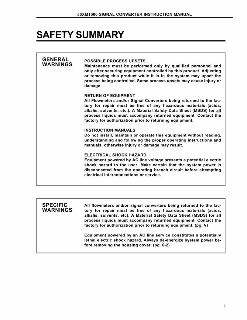
GENERALWARNINGS
POSSIBLE PROCESS UPSETSMaintenance must be performed only by qualified personnel andonly after securing equipment controlled by this product. Adjustingor removing this product while it is in the system may upset theprocess being controlled. Some process upsets may cause injury ordamage.
RETURN OF EQUIPMENTAll Flowmeters and/or Signal Converters being returned to the fac-tory for repair must be free of any hazardous materials (acids,alkalis, solvents, etc.). A Material Safety Data Sheet (MSDS) for allprocess liquids must accompany returned equipment. Contact thefactory for authorization prior to returning equipment.
INSTRUCTION MANUALSDo not install, maintain or operate this equipment without reading,understanding and following the proper operating instructions andmanuals, otherwise injury or damage may result.
ELECTRICAL SHOCK HAZARDEquipment powered by AC line voltage presents a potential electricshock hazard to the user. Make certain that the system power isdisconnected from the operating branch circuit before attemptingelectrical interconnections or service.
SPECIFICWARNINGS
All flowmeters and/or signal converters being returned to the fac-tory for repair must be free of any hazardous materials (acids,alkalis, solvents, etc). A Material Safety Data Sheet (MSDS) for allprocess liquids must accompany returned equipment. Contact thefactory for authorization prior to returning equipment. (pg. V)
Equipment powered by an AC line service constitutes a potentiallylethal electric shock hazard. Always de-energize system power be-fore removing the housing cover. (pg. 6-2)
50XM1000 SIGNAL CONVERTER INSTRUCTION MANUAL
I
SPECIFICCAUTIONS
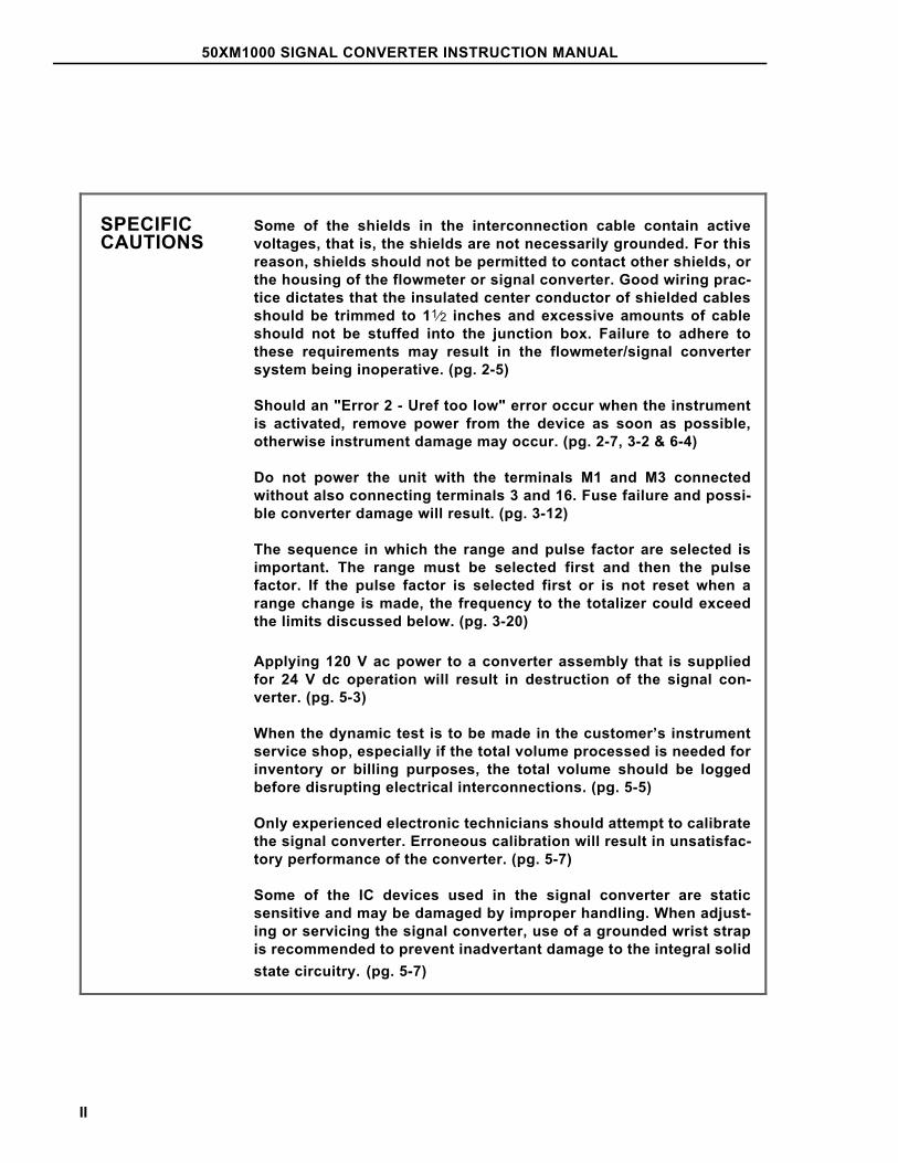
Some of the shields in the interconnection cable contain activevoltages, that is, the shields are not necessarily grounded. For thisreason, shields should not be permitted to contact other shields, orthe housing of the flowmeter or signal converter. Good wiring prac-tice dictates that the insulated center conductor of shielded cablesshould be trimmed to 11⁄2 inches and excessive amounts of cableshould not be stuffed into the junction box. Failure to adhere tothese requirements may result in the flowmeter/signal convertersystem being inoperative. (pg. 2-5)
Should an "Error 2 - Uref too low" error occur when the instrumentis activated, remove power from the device as soon as possible,otherwise instrument damage may occur. (pg. 2-7, 3-2 & 6-4)
Do not power the unit with the terminals M1 and M3 connectedwithout also connecting terminals 3 and 16. Fuse failure and possi-ble converter damage will result. (pg. 3-12)
The sequence in which the range and pulse factor are selected isimportant. The range must be selected first and then the pulsefactor. If the pulse factor is selected first or is not reset when arange change is made, the frequency to the totalizer could exceedthe limits discussed below. (pg. 3-20)
Applying 120 V ac power to a converter assembly that is suppliedfor 24 V dc operation will result in destruction of the signal con-verter. (pg. 5-3)
When the dynamic test is to be made in the customer’s instrumentservice shop, especially if the total volume processed is needed forinventory or billing purposes, the total volume should be loggedbefore disrupting electrical interconnections. (pg. 5-5)
Only experienced electronic technicians should attempt to calibratethe signal converter. Erroneous calibration will result in unsatisfac-tory performance of the converter. (pg. 5-7)
Some of the IC devices used in the signal converter are staticsensitive and may be damaged by improper handling. When adjust-ing or servicing the signal converter, use of a grounded wrist strapis recommended to prevent inadvertant damage to the integral solidstate circuitry. (pg. 5-7)
50XM1000 SIGNAL CONVERTER INSTRUCTION MANUAL
II
GÉNÉRAUXAVERTISSEMENTS
PROBLÈMES POTENTIELS. La maintenance doit être réaliséepar du personnel qualifié et seulement après avoir sécuriséles équipements contrôlés par ce produit. L’ajustement ou ledémontage de ce produit lorsqu’il est lié au système peutentraîner des dysfonctionnements dans le procédé qu’il con-trôle. Ces dysfonctionnements peuvent entraîner des bles-sures ou des dommages.
RETOUR D’ÉQUIPEMENT. Tout débitmètre et(ou) convert-isseur retourné à the factory pour réparation doit être exemptde toute trace de produit dangereux (acide, base, solvant, …). Un certificat de sécurité matériel doit être joint pour tousles liquides utilisés dans le procédé. Contacter the factorypour autorisation avant renvoi du matériel.
MANUEL DE MISE EN ROUTE. Ne pas installer, maintenir ouutiliser cet équipement sans avoir lu, compris et suivi lesinstructions et manuels, dans le cas contraire il y a risqued’entraîner blessures ou dommages.
RISQUE DE CHOC ÉLECTRIQUELes équipements alimentés en courant alternatif constituentun risque de choc électrique potentiel pour l’utilisateur. As-surez-vous que les câbles d’alimentation amont sont décon-nectés avant de procéder à des branchements, des essais outests.
SPÉCIFIQUESAVERTISSEMENTS
Tout débitmètre et(ou) convertisseur retourné à the factorypour réparation doit être exempt de toute trace de produitdangereux (acide, base, solvant, … ). Un certificat de sécuritématériel doit être joint pour tous les liquides utilisés dans leprocédé. Contacter the factory pour autorisation avant renvoidu matériel. (pg. V)
RISQUE DE CHOC ÉLECTRIQUE. Le matériel actionné par unservice de ligne à C.A. constitue un risque potentiellementmortel de décharge électrique. Déactivez toujours la puis-sance de système avant de retirer la couverture de logement.(pg. 6-2)
50XM1000 SIGNAL CONVERTER INSTRUCTION MANUAL
III
SPÉCIFIQUESATTENTIONS
Certains des boucliers dans le câble d’interconnexion con-tiennent des tensions actives, c.-à-d., les boucliers ne sontpas nécessairement fondus. Pour cette raison, des boucliersne devraient pas être autorisés pour entrer en contact avecd’autres boucliers, ou le logement du convertisseur de débit-mètre ou de signal. Bon câblage pratique dicter que isolercentral conducteur protéger câble devoir équilibrer 11⁄2pouce et excessif quantité câble devoir non bourrer dans dejonction boîte. Le manque d’adhérer à ces conditions peutavoir comme conséquence le système de convertisseur deflowmeter/signal étant inopérant. (pg. 2-5)
N’actionnez pas l’unité avec les terminaux M1 et M3 reliésans terminaux se reliants également 3 et 16. Fondez lapanne et les dommages possibles de convertisseur résul-teront. (pg. 3-12)
L’ordre dans lequel le facteur d’intervalle et d’impulsion sontchoisis est important. L’intervalle doit d’abord et puis êtrechoisi le facteur d’impulsion. Si le facteur d’impulsion estchoisi d’abord ou n’est pas remis à l’état initial quand unchangement d’intervalle est fait, la fréquence au totalisateurpourrait dépasser les limites discutées ci-dessous. (pg. 3-20)
Appliquer le courant alternatif de 120 V à un convertisseurqui est fourni pour 24 Vdc aura comme conséquence la de-struction du convertisseur de signal. (pg. 5-3)
Quand l’essai dynamique doit être fait dans le système deservice de l’instrument du client, particulièrement si tout levolume traité est nécessaire pour des buts de inventaire oude facturation, tout le volume devrait être enregistré avantdes interconnexions électriques de perturbation. (pg. 5-5)
Seulement les techniciens électroniques expérimentésdevraient essayer de calibrer le convertisseur de signal.L’étalonnage incorrect aura comme conséquence l’exécutioninsuffisante du convertisseur. (pg. 5-7)
Certains Circuits Intégrés utilisés dans le convertisseur sontsensibles à l’électricité statique et peuvent être endommagéspar une mauvaise manipulation. Pendant l’ajustement ou lamaintenance d’un convertisseur, l’utilisation d’un braceletantistatique est recommandé pour éviter la destruction parinadvertance d’un circuit intégré. (pg. 5-7)
50XM1000 SIGNAL CONVERTER INSTRUCTION MANUAL
IV
READ FIRST
WARNING
INSTRUCTION MANUALSDo not install, maintain, or operate this equipment without reading,
understanding and following the proper factory-supplied instructions andmanuals, otherwise injury or damage may result.
RETURN OF EQUIPMENTAll Flowmeters and/or Signal Converters being returned to the factory for repair
must be free of any hazardous materials (acids, alkalis, solvents, etc). AMaterial Safety Data Sheet (MSDS) for all process liquids must accompanyreturned equipment. Contact the factory for authorization prior to returning
equipment.
Read these instructions before starting installation; save these instructions for future reference.
Contacting the Factory. . .Should assistance be required with any of the company’s products, contact the following:
Telephone:
Automation Services Call Center1-800-HELP-365
E-Mail:
50XM1000 SIGNAL CONVERTER INSTRUCTION MANUAL
V
The NEMA 4X rating applies to the meter body and electronics enclosure only. The following accessories (ifsupplied) may not meet NEMA 4X unless specifically ordered as NEMA 4X:
• meter flanges
• meter installation hardware: studs, nuts, bolts
• enclosure mounting hardware for pipe or wall mounting
• conduit hardware
This product is painted with a high performance epoxy paint. The corrosion protection provided by this finishis only effective if the finish is unbroken. It is the users’ responsibility to "touch-up" any damage that hasoccurred to the finish during shipping or installation of the product. Special attention must be given to: meterflange bolting, pipe mounting of electronics, conduit entries and covers that are removed to facilitateinstallation or repair. For continued corrosion protection throughout the product life, it is the users’ responsi-bility to maintain the product finish. Incidental scratches and other finish damage must be repaired andpromptly re-painted with approved touch-up paint. Provide the model number and size of your product to thenearest factory representative to obtain the correct touch-up paint.
50XM1000 SIGNAL CONVERTER INSTRUCTION MANUAL
VI
1.0 INTRODUCTION
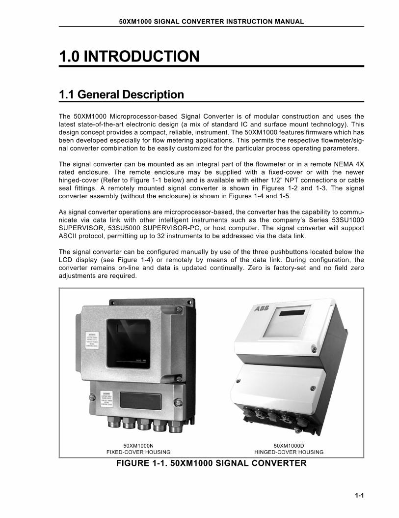
1.1 General DescriptionThe 50XM1000 Microprocessor-based Signal Converter is of modular construction and uses thelatest state-of-the-art electronic design (a mix of standard IC and surface mount technology). Thisdesign concept provides a compact, reliable, instrument. The 50XM1000 features firmware which hasbeen developed especially for flow metering applications. This permits the respective flowmeter/sig-nal converter combination to be easily customized for the particular process operating parameters.
The signal converter can be mounted as an integral part of the flowmeter or in a remote NEMA 4Xrated enclosure. The remote enclosure may be supplied with a fixed-cover or with the newerhinged-cover (Refer to Figure 1-1 below) and is available with either 1/2" NPT connections or cableseal fittings. A remotely mounted signal converter is shown in Figures 1-2 and 1-3. The signalconverter assembly (without the enclosure) is shown in Figures 1-4 and 1-5.
As signal converter operations are microprocessor-based, the converter has the capability to commu-nicate via data link with other intelligent instruments such as the company’s Series 53SU1000SUPERVISOR, 53SU5000 SUPERVISOR-PC, or host computer. The signal converter will supportASCII protocol, permitting up to 32 instruments to be addressed via the data link.
The signal converter can be configured manually by use of the three pushbuttons located below theLCD display (see Figure 1-4) or remotely by means of the data link. During configuration, theconverter remains on-line and data is updated continually. Zero is factory-set and no field zeroadjustments are required.
FIGURE 1-1. 50XM1000 SIGNAL CONVERTER
50XM1000NFIXED-COVER HOUSING
50XM1000DHINGED-COVER HOUSING
50XM1000 SIGNAL CONVERTER INSTRUCTION MANUAL
1-1
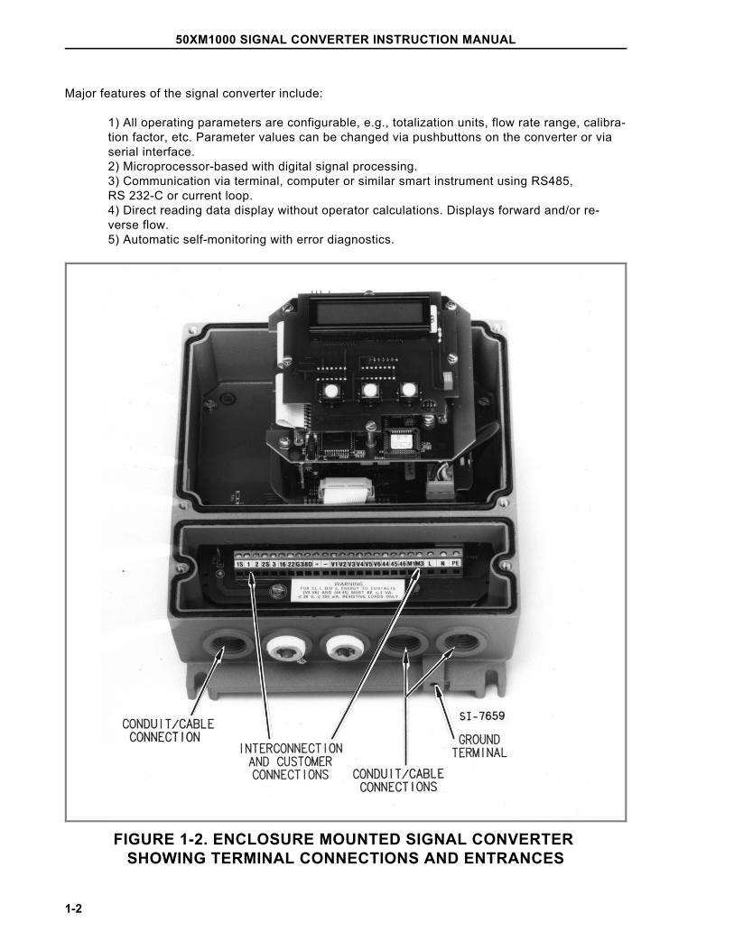
Major features of the signal converter include:
1) All operating parameters are configurable, e.g., totalization units, flow rate range, calibra-tion factor, etc. Parameter values can be changed via pushbuttons on the converter or viaserial interface.2) Microprocessor-based with digital signal processing.3) Communication via terminal, computer or similar smart instrument using RS485, RS 232-C or current loop.4) Direct reading data display without operator calculations. Displays forward and/or re-verse flow.5) Automatic self-monitoring with error diagnostics.
FIGURE 1-2. ENCLOSURE MOUNTED SIGNAL CONVERTER SHOWING TERMINAL CONNECTIONS AND ENTRANCES
50XM1000 SIGNAL CONVERTER INSTRUCTION MANUAL
1-2
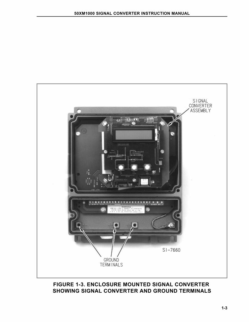
FIGURE 1-3. ENCLOSURE MOUNTED SIGNAL CONVERTER SHOWING SIGNAL CONVERTER AND GROUND TERMINALS
50XM1000 SIGNAL CONVERTER INSTRUCTION MANUAL
1-3
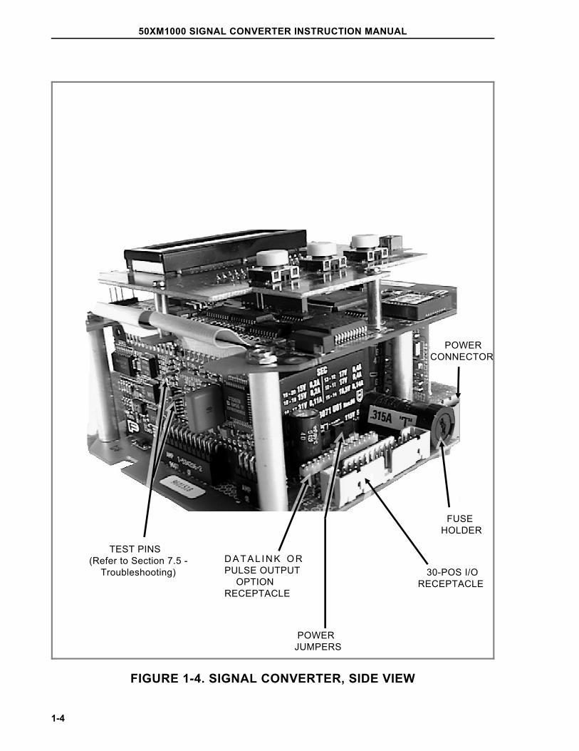
FIGURE 1-4. SIGNAL CONVERTER, SIDE VIEW
POWERCONNECTOR
TEST PINS(Refer to Section 7.5 - Troubleshooting)
D A T A L I N K O RPULSE OUTPUT OPTIONRECEPTACLE
30-POS I/ORECEPTACLE
FUSEHOLDER
POWERJUMPERS
50XM1000 SIGNAL CONVERTER INSTRUCTION MANUAL
1-4
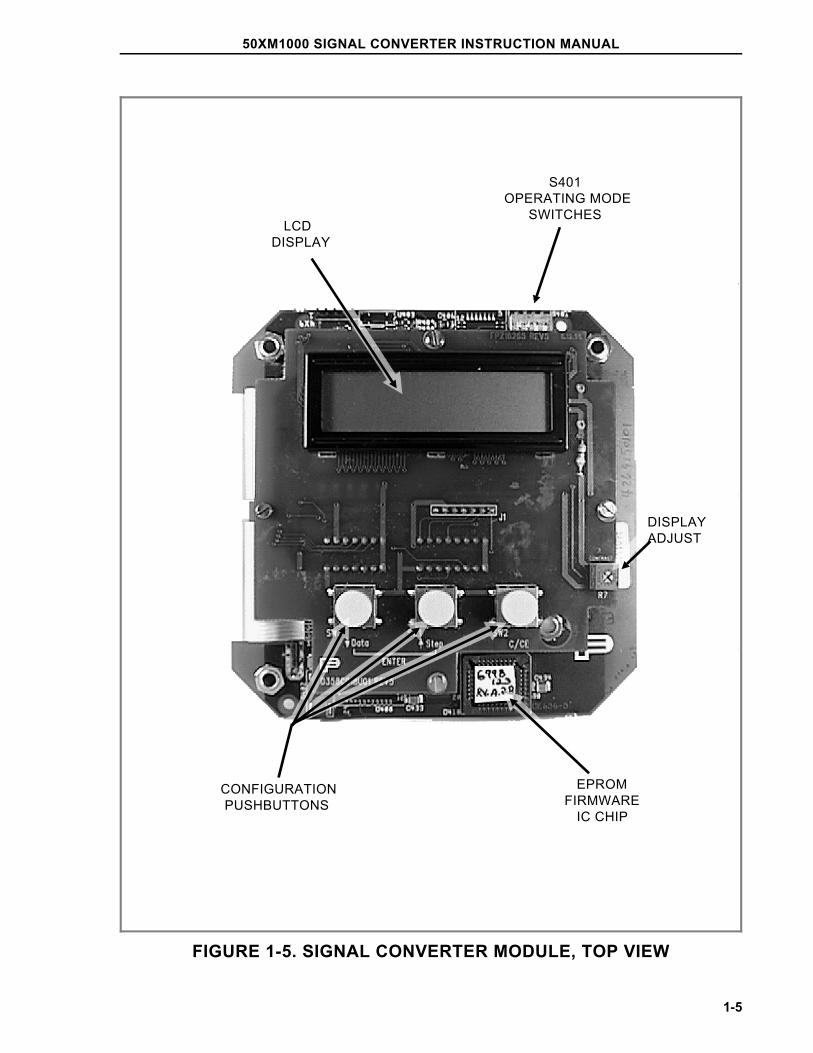
FIGURE 1-5. SIGNAL CONVERTER MODULE, TOP VIEW
LCDDISPLAY
S401OPERATING MODE SWITCHES
CONFIGURATION PUSHBUTTONS
EPROMFIRMWARE IC CHIP
DISPLAYADJUST
50XM1000 SIGNAL CONVERTER INSTRUCTION MANUAL
1-5
1.2. Model Number BreakdownRefer to the data sheet or instrument tag on the signal converter for the model number of the signalconverter. The details of a model number are defined as follows:
50XM1 _ _ X _ _ _ _ AA _ _ 2 _
Engineering Reference
Excitation Frequency6.25 Hz (50 Hz)12.5 Hz (50 Hz)7.5 Hz (60 Hz)15 Hz (60 Hz)6.25 Hz (DC)12.5 Hz (DC)7.5 Hz (DC)15 Hz (DC)
12345678
Design LevelFixed CoverHinged Cover
ND
Software Level X
CertificationNoneFM Approved - Primary Flowmeter & Remote SignalConverter: Non-Incendive ClI, Div 2, Gp.A,B,C & D,Dust-Ignition Proof ClII, Div 1, Gp.E,F & G andsuitable for ClIII, Div 1; Outdoor HazardousLocations, NEMA 4X. Integral Signal Converterenclosure additionally approved: Dust-Ignition ProofClII, Div 1, Gp.E,F & G and suitable for ClIII, Div1; Accidental Submergence, 33ft H2O/48 h (10 mH2O/48 h)
A
K
EnclosureNEMA 4X Field Housing w/ Window & Cable Seal FittingsNEMA 4X Field Housing w/ Window & 1/2" NPT Fittings19" Rack-Mount (Not currently available)NEMA 4X Field Housing w/ Window & Cable Seal Fittings,Level 4 Protection, Tropical High-Moisture ProtectionNEMA 4X Field Housing w/ Window & 1/2" NPT Fittings,Level 4 Protection, Tropical High-Moisture Protection
BDM
P
Q
Contact OutputsOptocouplerRelay
12
50XM1000 SIGNAL CONVERTER INSTRUCTION MANUAL
1-6
1.2 Model Number Breakdown (continued)
50XM1 _ _ X _ _ _ _ AA _ _ 2 _
Output OptionsNoneActive Scaled Pulse (Fwd. & Rev.)Relay Contact Scaled Pulse, Fwd. & Rev.Optocoupled Scaled Pulse, Fwd. & Rev.RS485 PortRS232C PortRS485 Port w/ Opto Pulse Output ForwardRS232C Port w/ Opto Pulse Output ForwardRS485 Port w/ Relay Pulse Output Forward
012345678
OperationContinuous Mode AA
Additional OptionsEmpty Pipe DetectorNo Empty Pipe DetectorEmpty Pipe Detector & External Totalizer ResetExternal Totalizer ResetHART Protocol & Empty Pipe Detector HART ProtocolHART Protocol, External Totalizer Reset & Empty Pipe DetectorHART Protocol & External Totalizer Reset
ABEFGHJK
Electrical Requirements220/230/240 VAC, 50/60 Hz110/115/120 VAC, 50/60 Hz48 VDC24 VDC
ACGH
Customer LanguageEnglish 2
Output Current0-20 mA4-20 mA
12
50XM1000 SIGNAL CONVERTER INSTRUCTION MANUAL
1-7
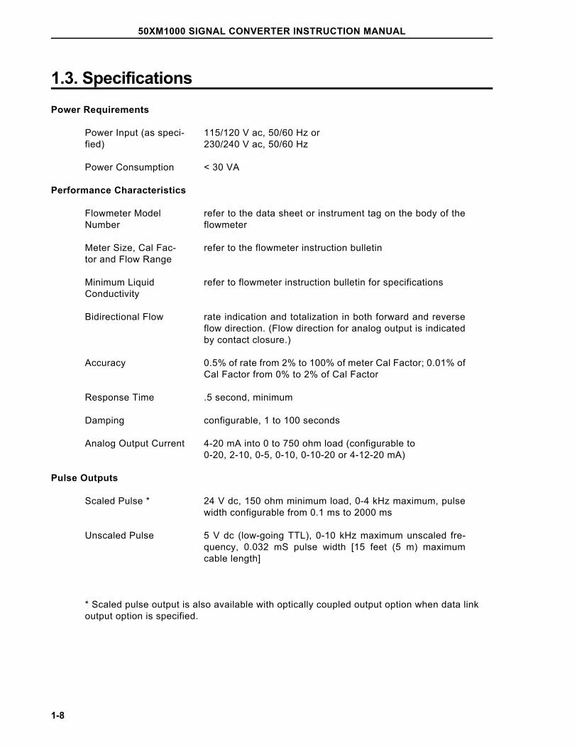
1.3. SpecificationsPower Requirements
Power Input (as speci-fied)
115/120 V ac, 50/60 Hz or230/240 V ac, 50/60 Hz
Power Consumption < 30 VA
Performance Characteristics
Flowmeter ModelNumber
refer to the data sheet or instrument tag on the body of theflowmeter
Meter Size, Cal Fac-tor and Flow Range
refer to the flowmeter instruction bulletin
Minimum Liquid Conductivity
refer to flowmeter instruction bulletin for specifications
Bidirectional Flow rate indication and totalization in both forward and reverseflow direction. (Flow direction for analog output is indicatedby contact closure.)
Accuracy 0.5% of rate from 2% to 100% of meter Cal Factor; 0.01% ofCal Factor from 0% to 2% of Cal Factor
Response Time .5 second, minimum
Damping configurable, 1 to 100 seconds
Analog Output Current 4-20 mA into 0 to 750 ohm load (configurable to0-20, 2-10, 0-5, 0-10, 0-10-20 or 4-12-20 mA)
Pulse Outputs
Scaled Pulse * 24 V dc, 150 ohm minimum load, 0-4 kHz maximum, pulsewidth configurable from 0.1 ms to 2000 ms
Unscaled Pulse 5 V dc (low-going TTL), 0-10 kHz maximum unscaled fre-quency, 0.032 mS pulse width [15 feet (5 m) maximumcable length]
* Scaled pulse output is also available with optically coupled output option when data linkoutput option is specified.
50XM1000 SIGNAL CONVERTER INSTRUCTION MANUAL
1-8
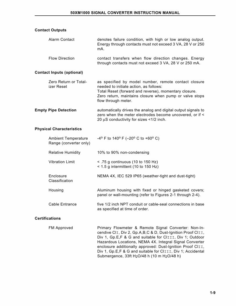
Contact Outputs
Alarm Contact denotes failure condition, with high or low analog output.Energy through contacts must not exceed 3 VA, 28 V or 250mA.
Flow Direction contact transfers when flow direction changes. Energythrough contacts must not exceed 3 VA, 28 V or 250 mA.
Contact Inputs (optional)
Zero Return or Total-izer Reset
as specified by model number, remote contact closureneeded to initiate action, as follows: Total Reset (forward and reverse), momentary closure. Zero return, maintains closure when pump or valve stopsflow through meter.
Empty Pipe Detection automatically drives the analog and digital output signals tozero when the meter electrodes become uncovered, or if <20 µS conductivity for sizes <1/2 inch.
Physical Characteristics
Ambient TemperatureRange (converter only)
-4o F to 140o F (–20o C to +60o C)
Relative Humidity 10% to 90% non-condensing
Vibration Limit < .75 g continuous (10 to 150 Hz)< 1.5 g intermittent (10 to 150 Hz)
EnclosureClassification
NEMA 4X, IEC 529 IP65 (weather-tight and dust-tight)
Housing Aluminum housing with fixed or hinged gasketed covers;panel or wall-mounting (refer to Figures 2-1 through 2-4).
Cable Entrance five 1/2 inch NPT conduit or cable-seal connections in baseas specified at time of order.
Certifications
FM Approved Primary Flowmeter & Remote Signal Converter: Non-In-cendive ClI, Div 2, Gp.A,B,C & D, Dust-Ignition Proof ClII,Div 1, Gp.E,F & G and suitable for ClIII, Div 1; OutdoorHazardous Locations, NEMA 4X. Integral Signal Converterenclosure additionally approved: Dust-Ignition Proof ClII,Div 1, Gp.E,F & G and suitable for ClIII, Div 1; AccidentalSubmergence, 33ft H2O/48 h (10 m H2O/48 h)
50XM1000 SIGNAL CONVERTER INSTRUCTION MANUAL
1-9
2.0 INSTALLATION2.1 InspectionThe 50XM1000 signal converter is shipped in a heavy-duty protective container that is speciallydesigned to provide adequate protection of the equipment during transit. The packaging is certifiedfor air shipment by the Container Testing Laboratory. An itemized list of all items included in theshipment is attached to the shipping container.
The signal converter can be supplied as an integrally mounted assembly of the flowmeter, or in aseparate wall or panel mounted enclosure. When the 50XM Converter is integrally mounted with theflowmeter, outline and mounting dimensions are provided in the instruction bulletin supplied with theflowmeter. Outline dimensions and clearance requirements for the remotely mounted signal con-verter are provided in Figures 2-1 through 2-4.
The equipment should be inspected immediately upon arrival for indications of damage that mayhave occurred during shipment. In most cases a careful visual inspection is all that is required toestablish apparent damage.
All damage claims should be reported to the shipping agent involved before installing the equipment.In the event damage is such that faulty operation is likely to result, this damage should be brought tothe attention of the our Service Department before installation. Always reference the completeinstrument serial number and model number in all correspondence concerning the equipment sup-plied.
Following inspection of the shipment contents, it is suggested that all items be carefully replaced inthe shipping container for storage and/or transit to the installation site. The use of normal care in thehandling and installation of this equipment will contribute substantially toward satisfactory perform-ance.
50XM1000 SIGNAL CONVERTER INSTRUCTION MANUAL
2-1
2.2 Location and MountingWhen the signal converter is integrally mounted, refer to the installation section of the instructionmanual supplied with the flowmeter for location and mounting requirements.
The installation site for the remotely mounted signal converter should be clean, well lighted andadequately ventilated. The remote mounted enclosure is designed to meet NEMA 4X standards andis suitable for indoor or outdoor installation in an environment that is within the temperature, humidityand vibration limits as shown in Section 1.3. Mounting dimensions for the wall or panel mountedenclosures are provided in Figures 2-1 through 2-4. Mounting hardware is to be supplied by the user.
Also, consideration should be given to access requirements for repair and maintenance of theequipment.
The installation site must be provided with a power source that is compatible with the signal converterpower requirements. Refer to the converter data tag for power requirements.
50XM1000 SIGNAL CONVERTER INSTRUCTION MANUAL
2-2
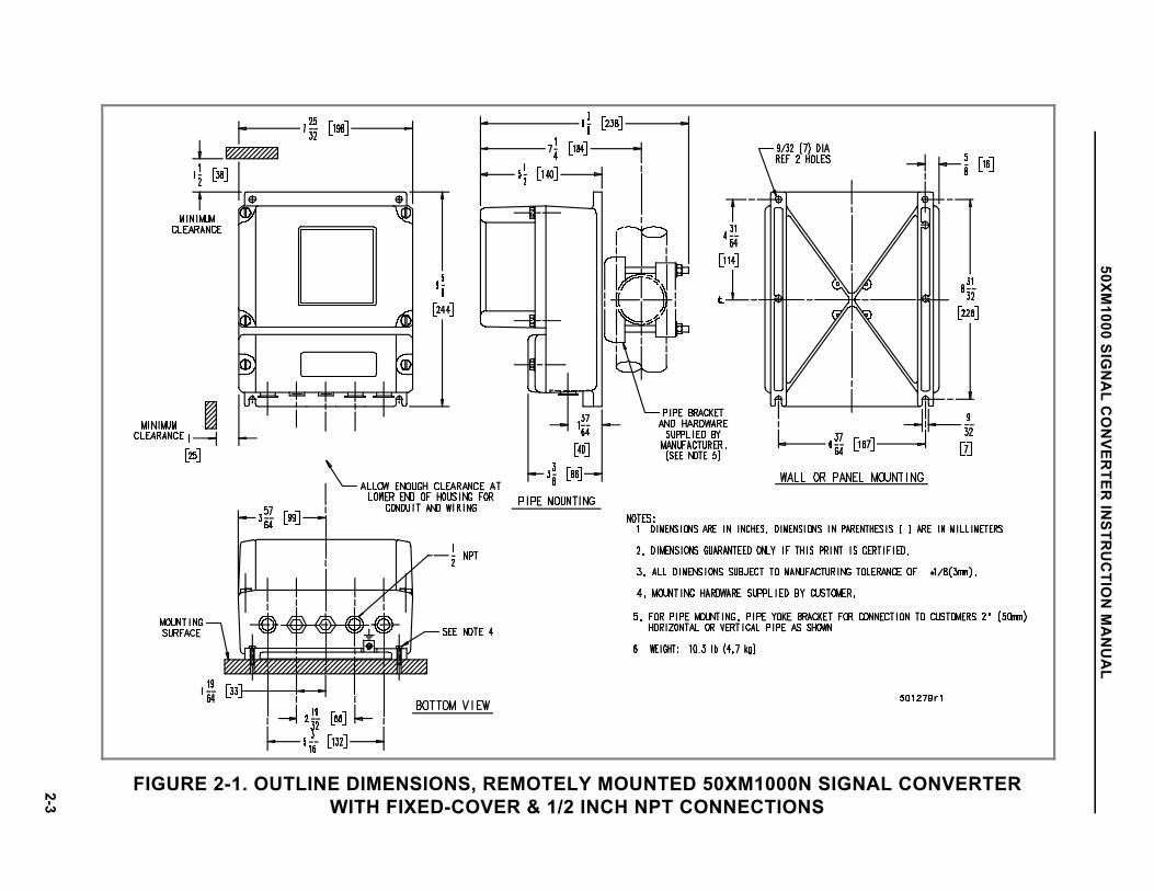
FIGURE 2-1. OUTLINE DIMENSIONS, REMOTELY MOUNTED 50XM1000N SIGNAL CONVERTERWITH FIXED-COVER & 1/2 INCH NPT CONNECTIONS
50XM1000 SIG
NA
L CO
NVER
TER IN
STRU
CTIO
N M
AN
UA
L
2-3
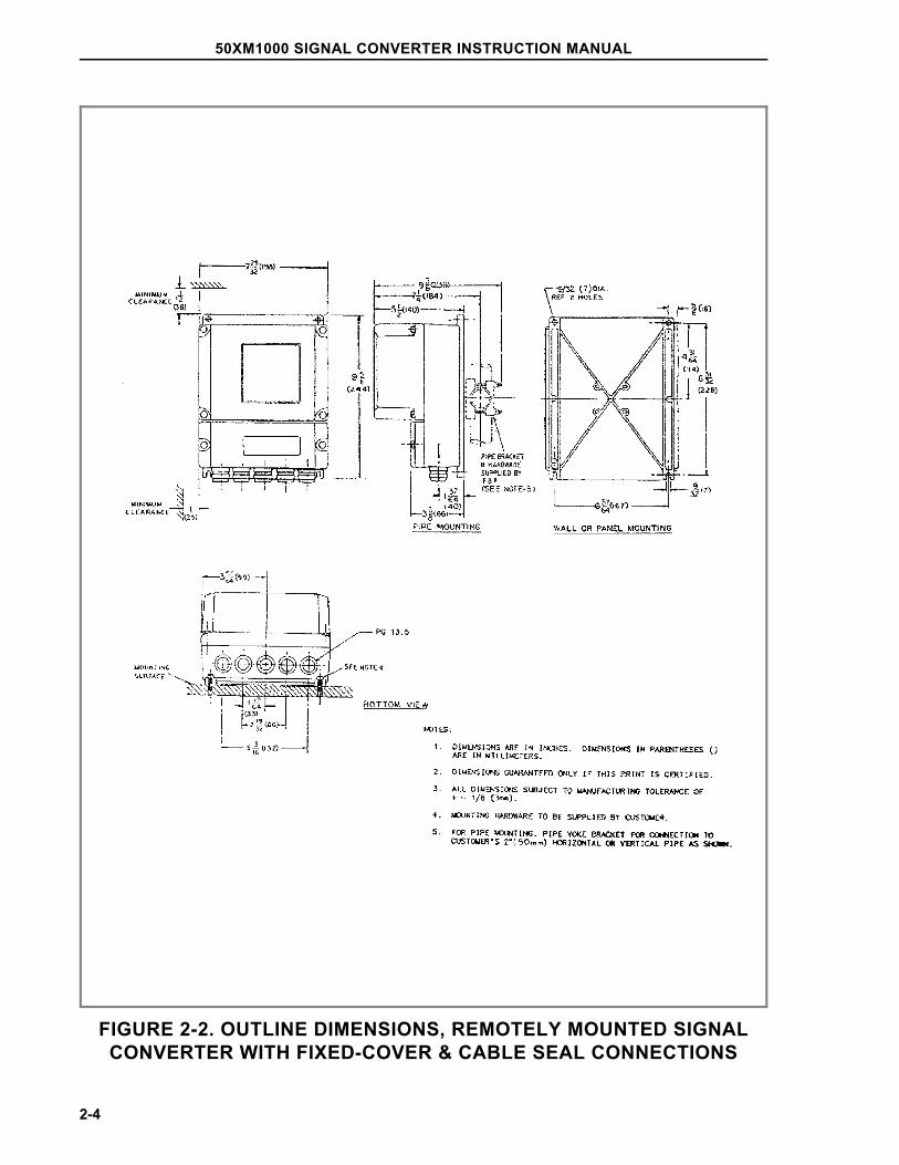
FIGURE 2-2. OUTLINE DIMENSIONS, REMOTELY MOUNTED SIGNALCONVERTER WITH FIXED-COVER & CABLE SEAL CONNECTIONS
50XM1000 SIGNAL CONVERTER INSTRUCTION MANUAL
2-4
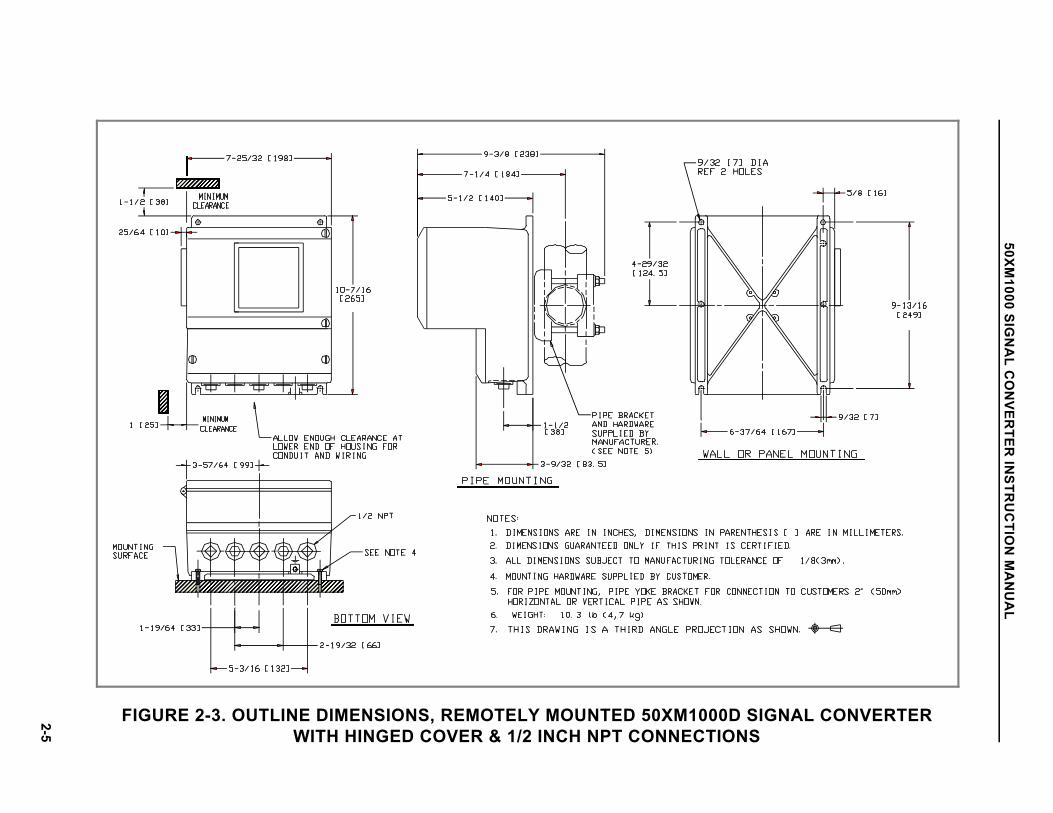
FIGURE 2-3. OUTLINE DIMENSIONS, REMOTELY MOUNTED 50XM1000D SIGNAL CONVERTERWITH HINGED COVER & 1/2 INCH NPT CONNECTIONS
50XM1000 SIG
NA
L CO
NVER
TER IN
STRU
CTIO
N M
AN
UA
L
2-5
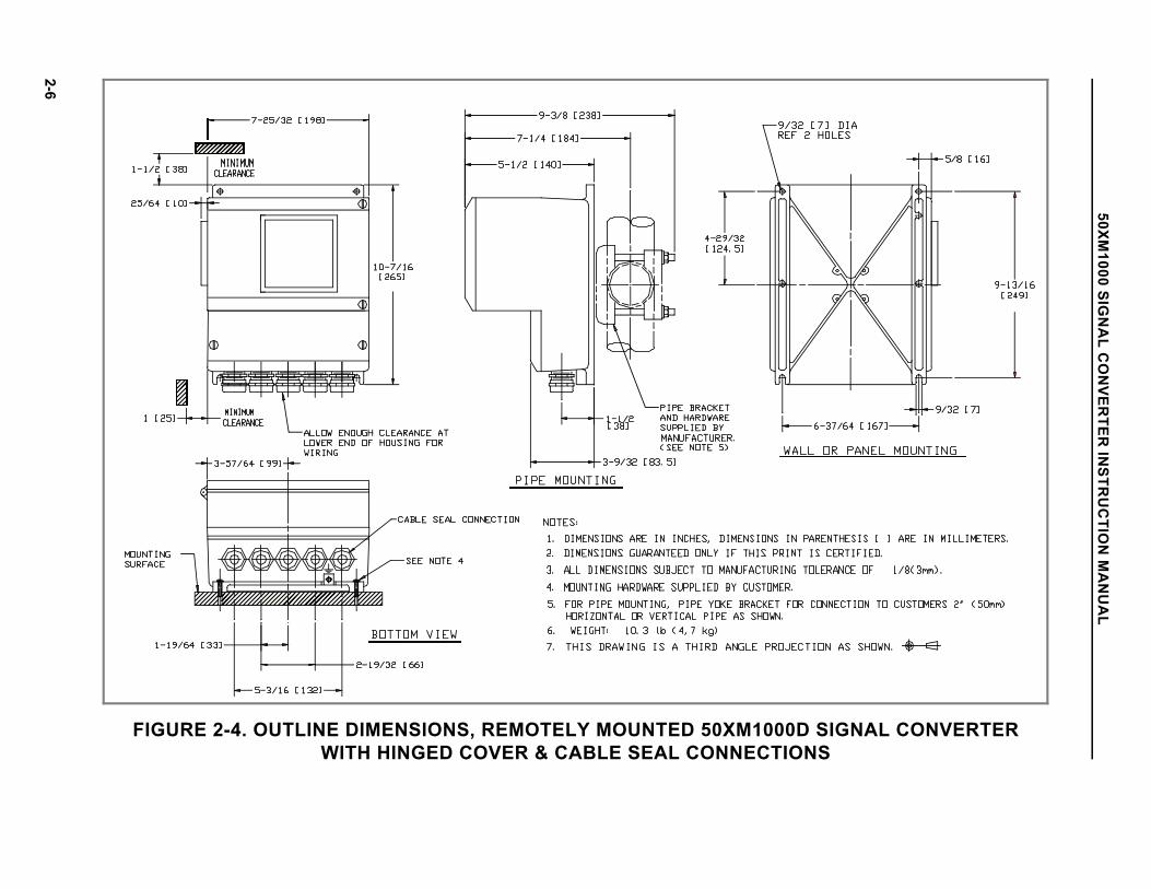
FIGURE 2-4. OUTLINE DIMENSIONS, REMOTELY MOUNTED 50XM1000D SIGNAL CONVERTERWITH HINGED COVER & CABLE SEAL CONNECTIONS
50XM1000 SIG
NA
L CO
NVER
TER IN
STRU
CTIO
N M
AN
UA
L
2-6
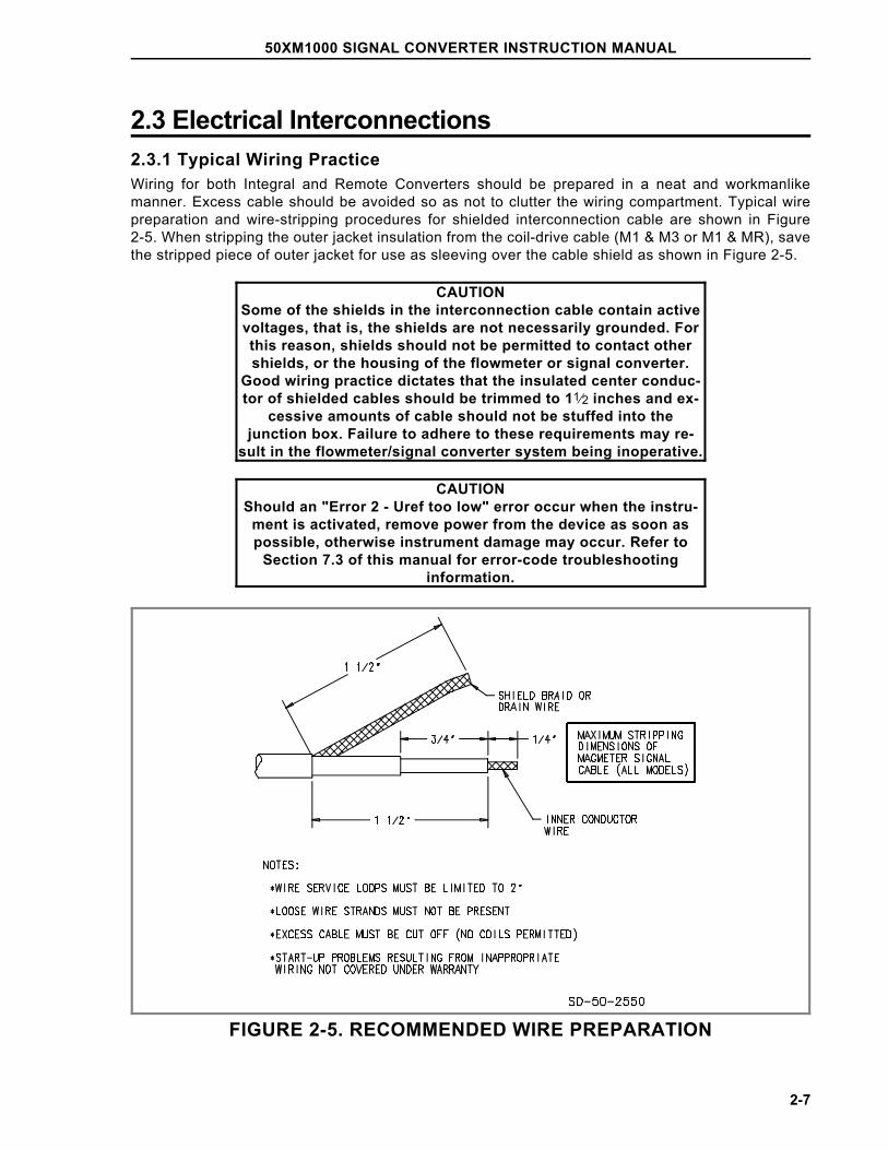
2.3 Electrical Interconnections2.3.1 Typical Wiring PracticeWiring for both Integral and Remote Converters should be prepared in a neat and workmanlikemanner. Excess cable should be avoided so as not to clutter the wiring compartment. Typical wirepreparation and wire-stripping procedures for shielded interconnection cable are shown in Figure2-5. When stripping the outer jacket insulation from the coil-drive cable (M1 & M3 or M1 & MR), savethe stripped piece of outer jacket for use as sleeving over the cable shield as shown in Figure 2-5.
CAUTIONSome of the shields in the interconnection cable contain activevoltages, that is, the shields are not necessarily grounded. Forthis reason, shields should not be permitted to contact othershields, or the housing of the flowmeter or signal converter.
Good wiring practice dictates that the insulated center conduc-tor of shielded cables should be trimmed to 11⁄2 inches and ex-
cessive amounts of cable should not be stuffed into thejunction box. Failure to adhere to these requirements may re-
sult in the flowmeter/signal converter system being inoperative.
CAUTIONShould an "Error 2 - Uref too low" error occur when the instru-
ment is activated, remove power from the device as soon aspossible, otherwise instrument damage may occur. Refer to
Section 7.3 of this manual for error-code troubleshootinginformation.
FIGURE 2-5. RECOMMENDED WIRE PREPARATION
50XM1000 SIGNAL CONVERTER INSTRUCTION MANUAL
2-7
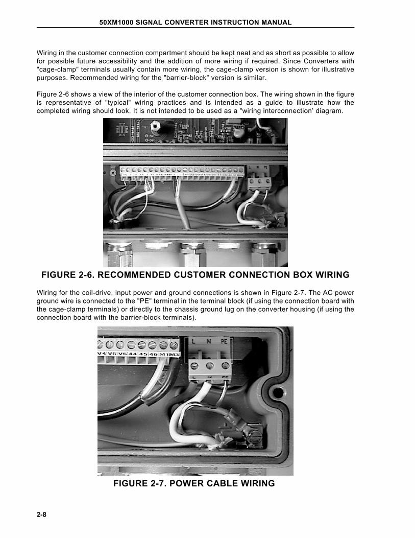
Wiring in the customer connection compartment should be kept neat and as short as possible to allowfor possible future accessibility and the addition of more wiring if required. Since Converters with"cage-clamp" terminals usually contain more wiring, the cage-clamp version is shown for illustrativepurposes. Recommended wiring for the "barrier-block" version is similar.
Figure 2-6 shows a view of the interior of the customer connection box. The wiring shown in the figureis representative of "typical" wiring practices and is intended as a guide to illustrate how thecompleted wiring should look. It is not intended to be used as a "wiring interconnection’ diagram.
FIGURE 2-6. RECOMMENDED CUSTOMER CONNECTION BOX WIRING
Wiring for the coil-drive, input power and ground connections is shown in Figure 2-7. The AC powerground wire is connected to the "PE" terminal in the terminal block (if using the connection board withthe cage-clamp terminals) or directly to the chassis ground lug on the converter housing (if using theconnection board with the barrier-block terminals).
FIGURE 2-7. POWER CABLE WIRING
50XM1000 SIGNAL CONVERTER INSTRUCTION MANUAL
2-8
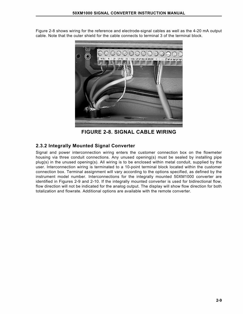
Figure 2-8 shows wiring for the reference and electrode-signal cables as well as the 4-20 mA outputcable. Note that the outer shield for the cable connects to terminal 3 of the terminal block.
FIGURE 2-8. SIGNAL CABLE WIRING
2.3.2 Integrally Mounted Signal ConverterSignal and power interconnection wiring enters the customer connection box on the flowmeterhousing via three conduit connections. Any unused opening(s) must be sealed by installing pipeplug(s) in the unused opening(s). All wiring is to be enclosed within metal conduit, supplied by theuser. Interconnection wiring is terminated to a 10-point terminal block located within the customerconnection box. Terminal assignment will vary according to the options specified, as defined by theinstrument model number. Interconnections for the integrally mounted 50XM1000 converter areidentified in Figures 2-9 and 2-10. If the integrally mounted converter is used for bidirectional flow,flow direction will not be indicated for the analog output. The display will show flow direction for bothtotalization and flowrate. Additional options are available with the remote converter.
50XM1000 SIGNAL CONVERTER INSTRUCTION MANUAL
2-9
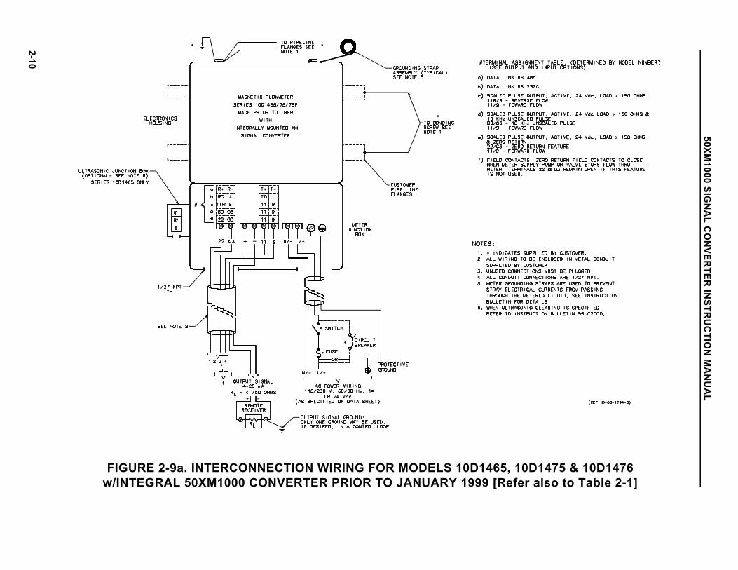
FIGURE 2-9a. INTERCONNECTION WIRING FOR MODELS 10D1465, 10D1475 & 10D1476w/INTEGRAL 50XM1000 CONVERTER PRIOR TO JANUARY 1999 [Refer also to Table 2-1]
50XM1000 SIG
NA
L CO
NVER
TER IN
STRU
CTIO
N M
AN
UA
L
2-10
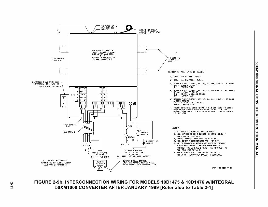
FIGURE 2-9b. INTERCONNECTION WIRING FOR MODELS 10D1475 & 10D1476 w/INTEGRAL50XM1000 CONVERTER AFTER JANUARY 1999 [Refer also to Table 2-1]
50XM1000 SIG
NA
L CO
NVER
TER IN
STRU
CTIO
N M
AN
UA
L
2-11
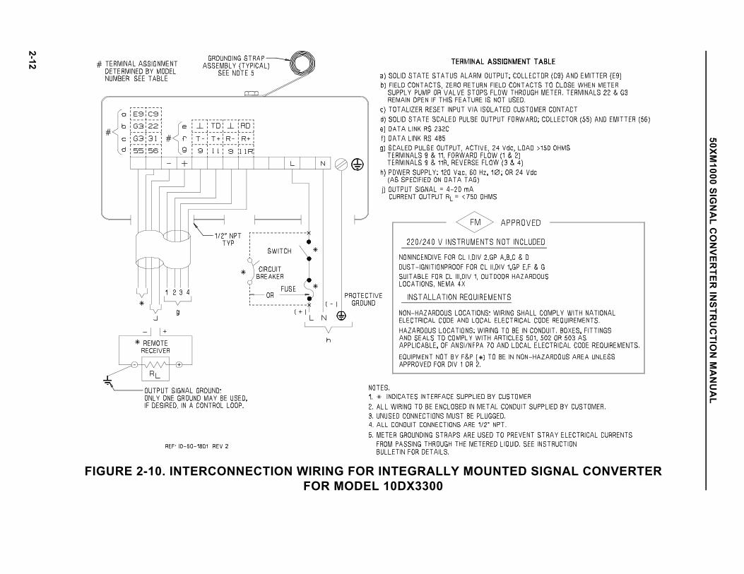
FIGURE 2-10. INTERCONNECTION WIRING FOR INTEGRALLY MOUNTED SIGNAL CONVERTERFOR MODEL 10DX3300
50XM1000 SIG
NA
L CO
NVER
TER IN
STRU
CTIO
N M
AN
UA
L
2-12
2.3.2 Remotely Mounted Signal ConverterThe signal converter customer connection box is supplied with five openings for 1/2 inch NPT conduitfittings or cable-seal cable fittings as specified at time of purchase. Any unused opening(s) must besealed by installing an applicable plug(s) in the unused opening(s). This is required to maintain theNEMA 4X rating of the enclosure. All interconnection wiring in North America is to be enclosed withinmetal conduit supplied by user.
The signal converter signal and power interconnection cables are to be terminated to the 25 pointterminal block located in the remote customer connection box. Certain terminal assignments vary inaccordance with the model number as defined in the terminal assignment table in Figures 2-11through 2-14. Note that the terminals labeled V1 through V4 are used for the active pulse output aswell as the data link. Consequently, only one of these can be selected as an option. If a pulse outputis required as well as the data link, the output pulse must be optocoupled, and is available onterminals 55 and 56 (V5 and V6). When this combination is selected, the alarm contact on terminalsV5 and V6 (39 and 40) is not available.
Unless otherwise specified, thirty feet (10 m) of signal and ground cable is supplied for connectingthe flowmeter process signal (1 and 2), reference signal (16 and 3-shield) and magnet coil drive (M1and M3-shield) to the remotely mounted signal converter. The flowmeter housing ground terminal isconnected to the signal converter housing ground terminal, which is connected to an external earthground. Refer to the flowmeter grounding procedure given in the instruction bulletin provided with theflowmeter.
2.3.2.1 Customer ConnectionsThe following descriptions are for a converter in a remote mounted enclosure. Converters which areintegrally mounted use subsets of these, and their application and availability varies with the modelnumber. Verify the applicable features by checking the model number.
Terminals 1S, 1, 2, and 2S These are the measuring electrodes of the flowmeter, along with their shields. The shield of eachelectrode is driven at the same potential as that electrode so as to minimize the effects of signalcable length.
Terminals 3 and 16 Terminal 3 is the circuit common of the magmeter measuring system, and is connected by thecustomer to a quality earth ground at the flowmeter. Terminal 16 is referred to as reference voltageand is proportional to the excitation current used for the primary. This voltage is regulated to ± 70 mVby the converter electronics. The wiring between the flowmeter and converter places 16 inside acable shielded by terminal 3.
Terminal 22 This terminal is referred to as X1 in the firmware, and can be configured for positive zero return ortotalizer reset. An isolated contact closure capable of passing 5 mA DC is required for activation ofthe selected function.
Terminal G3 This is the circuit common for all digital functions, which include the terminal 8D 10 kHz unscaledpulse and terminal 22. It is electrically connected to terminal 3 but should only be used for interfacewith terminals 8D and 22.
50XM1000 SIGNAL CONVERTER INSTRUCTION MANUAL
2-13
Terminal 8D This is an unscaled 0 to 10 kHz unscaled logic pulse representing zero to full scale (range value) flowof the converter. The pulses are fixed at 30 µsec width and make a logic transition from 5 volts to zerovolts. A maximum cable length of 15 feet (5 m) should be used when measuring this output.
Terminals + and - These terminals are the process current output. This is an active current output which can beconfigured by firmware to various levels and operating modes. The converter can source 20 mA intoa maximum of 750 ohms load resistance.
Terminals V1 - V4 The exact nomenclature of these terminals is determined by the option card selected for theconverter. Designations 9/11 (V1/V2) and 9/11R (V3/V4) denote a scaled pulse output. This may beeither opto coupled or active, with 11 being active for forward flow and 11R for reverse. Terminals 9are common for both flow directions. When an RS323C data link option is specified, V1 and V3 are common, while the converter transmitsdata out terminal V2 and receives it into V4.When the RS485 data link is specified, the converter will transmit data out V1 and V2, (V2 normallyhigh) and will receive data into V3 and V4, with the logic signal at V4 normally high going low.
Terminals V5 and V6 These terminals are used for alarm indication from the converter, and may be either a pair of relaycontacts or the collector (V6) and emitter (V5) of an opto coupler. These contacts are closed duringnormal operation and will open during any alarm condition shown on the converter display.
Terminals 44, 45 and 46 These terminals constitute the contacts of a form "C" relay which connects terminals 44 and 45 of anunpowered converter and connects 45 and 46 when the relay is energized by the converter. Thefirmware refers to these terminals as P1/P2, with an "on" or closed condition being one which willenergize the relay. The status of a P1/P2 connection may be considered analogous to that ofterminals 45 and 46.
Terminals M1 and M3 These terminals are intended to energize the magnet coils of the flowmeter. A shielded cable is usedfor this purpose, with M1 being the inner conductor and M3 having a relatively low millivoltage.
Terminals L, N, and GroundThese are the terminals used to power the system, with L being the voltage supply and N beingneutral. If the converter is purchased with DC power, then L is the positive connection. The groundterminal is for the converter enclosure and must be connected to ground at the local electricalservice.
50XM1000 SIGNAL CONVERTER INSTRUCTION MANUAL
2-14
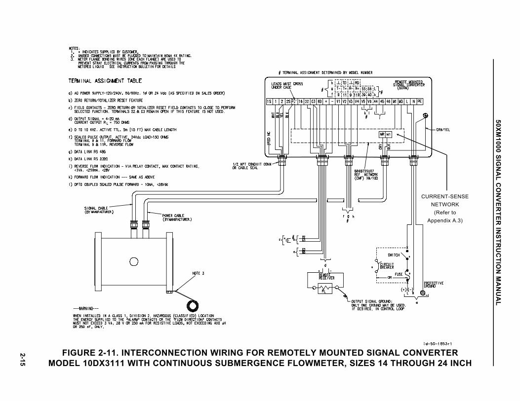
FIGURE 2-11. INTERCONNECTION WIRING FOR REMOTELY MOUNTED SIGNAL CONVERTERMODEL 10DX3111 WITH CONTINUOUS SUBMERGENCE FLOWMETER, SIZES 14 THROUGH 24 INCH
CURRENT-SENSENETWORK
(Refer toAppendix A.3)
50XM1000 SIG
NA
L CO
NVER
TER IN
STRU
CTIO
N M
AN
UA
L
2-15
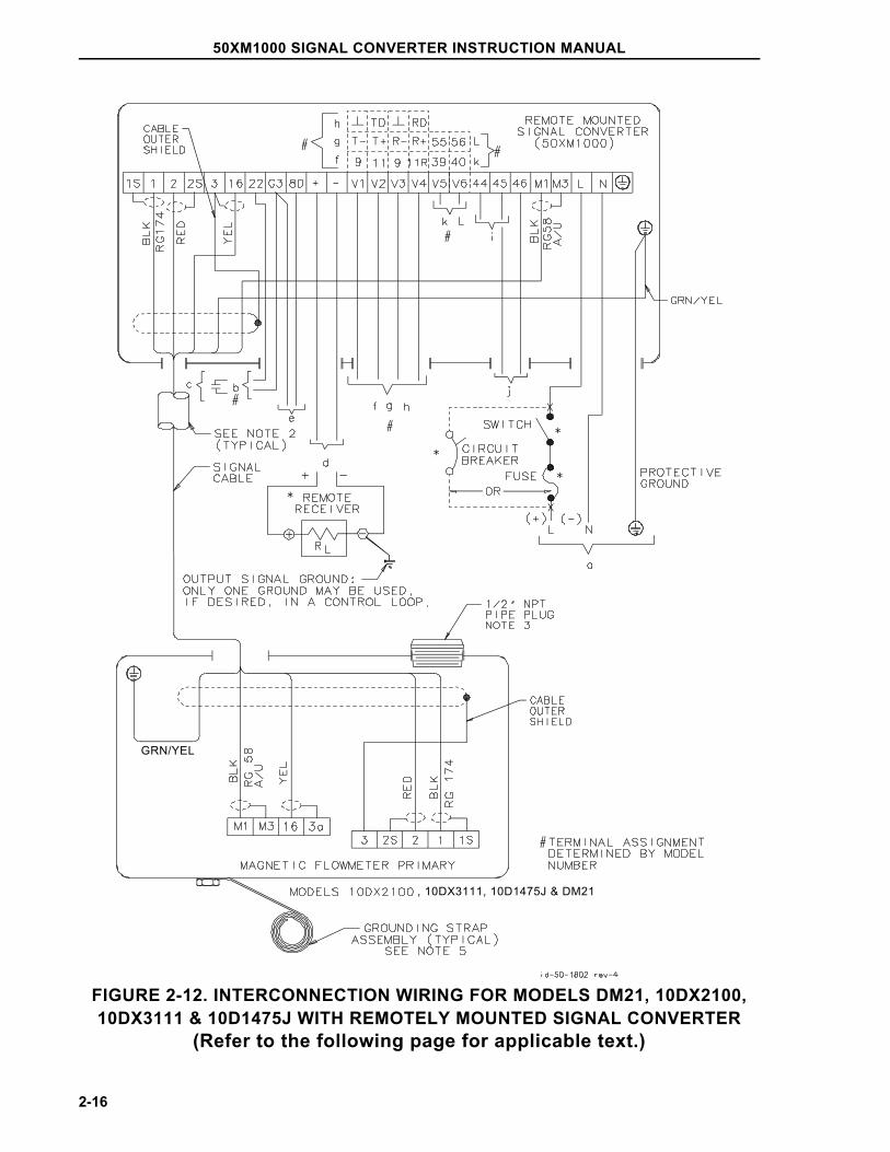
FIGURE 2-12. INTERCONNECTION WIRING FOR MODELS DM21, 10DX2100,10DX3111 & 10D1475J WITH REMOTELY MOUNTED SIGNAL CONVERTER
(Refer to the following page for applicable text.)
, 10DX3111, 10D1475J & DM21
GRN/YEL
50XM1000 SIGNAL CONVERTER INSTRUCTION MANUAL
2-16
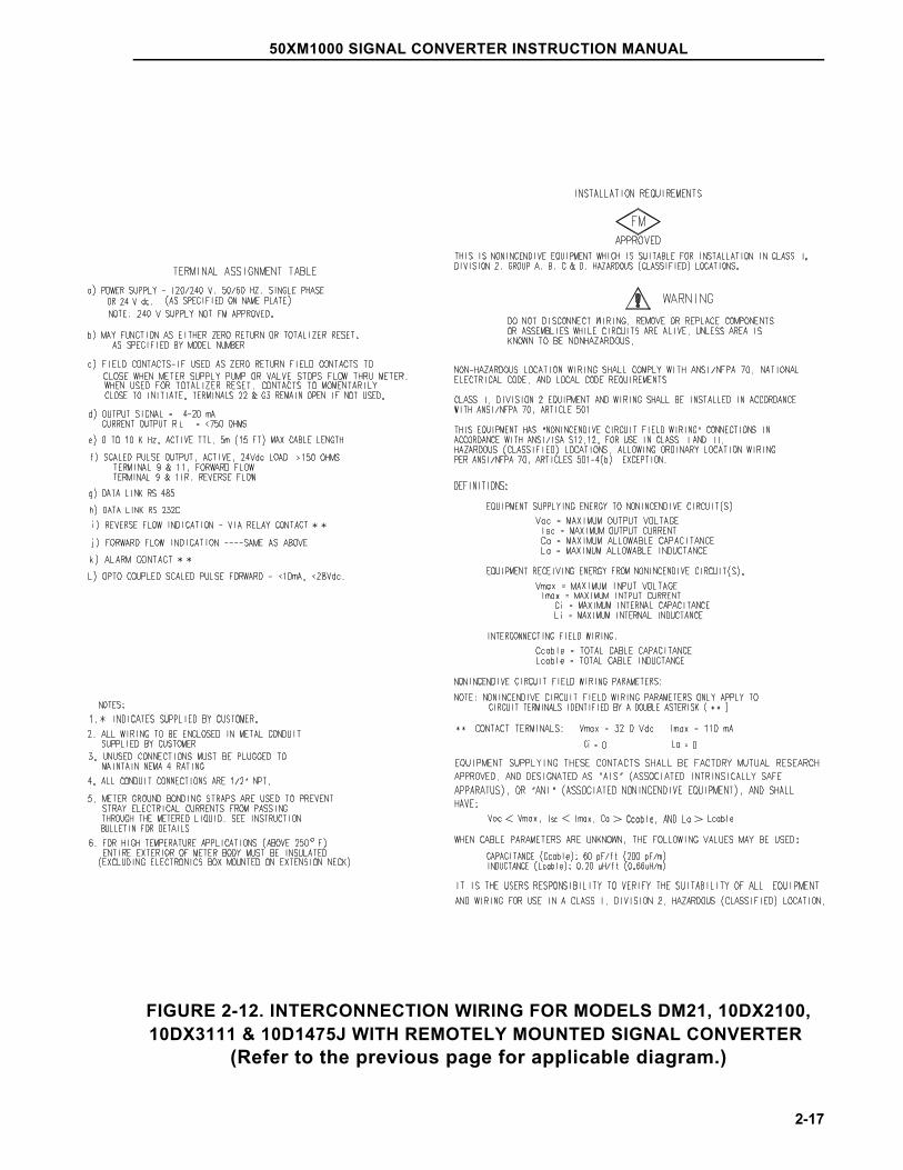
FIGURE 2-12. INTERCONNECTION WIRING FOR MODELS DM21, 10DX2100,10DX3111 & 10D1475J WITH REMOTELY MOUNTED SIGNAL CONVERTER
(Refer to the previous page for applicable diagram.)
50XM1000 SIGNAL CONVERTER INSTRUCTION MANUAL
2-17
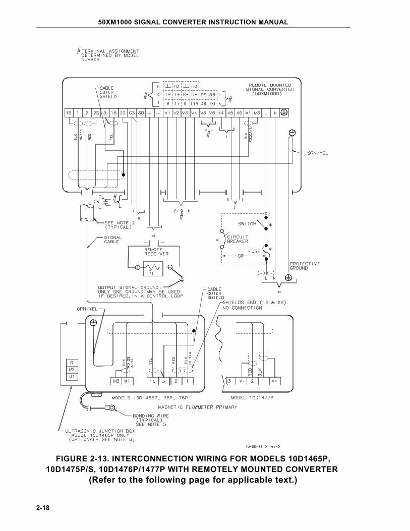
FIGURE 2-13. INTERCONNECTION WIRING FOR MODELS 10D1465P,10D1475P/S, 10D1476P/1477P WITH REMOTELY MOUNTED CONVERTER
(Refer to the following page for applicable text.)
50XM1000 SIGNAL CONVERTER INSTRUCTION MANUAL
2-18
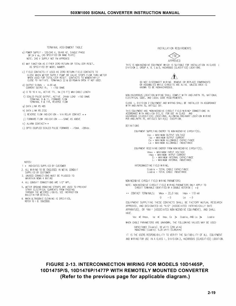
FIGURE 2-13. INTERCONNECTION WIRING FOR MODELS 10D1465P,10D1475P/S, 10D1476P/1477P WITH REMOTELY MOUNTED CONVERTER
(Refer to the previous page for applicable diagram.)
50XM1000 SIGNAL CONVERTER INSTRUCTION MANUAL
2-19
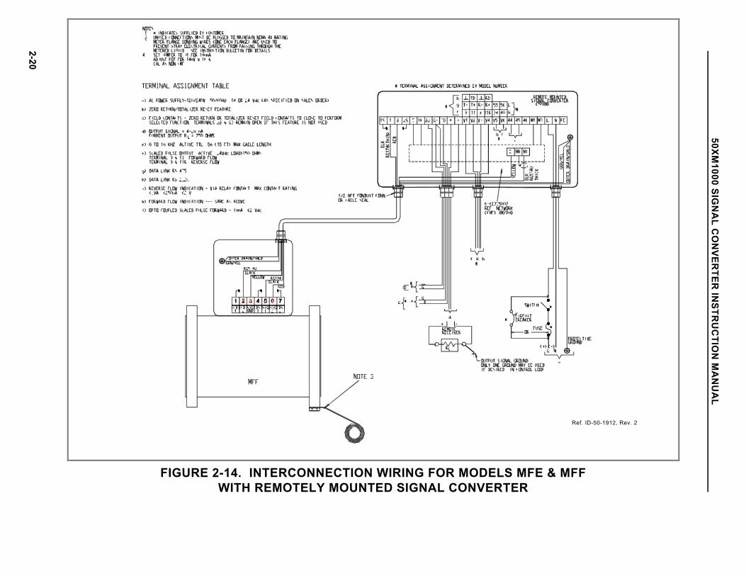
FIGURE 2-14. INTERCONNECTION WIRING FOR MODELS MFE & MFFWITH REMOTELY MOUNTED SIGNAL CONVERTER
Ref. ID-50-1912, Rev. 2
50XM1000 SIG
NA
L CO
NVER
TER IN
STRU
CTIO
N M
AN
UA
L
2-20
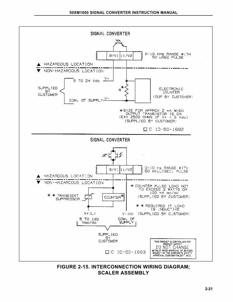
FIGURE 2-15. INTERCONNECTION WIRING DIAGRAM;SCALER ASSEMBLY
50XM1000 SIGNAL CONVERTER INSTRUCTION MANUAL
2-21
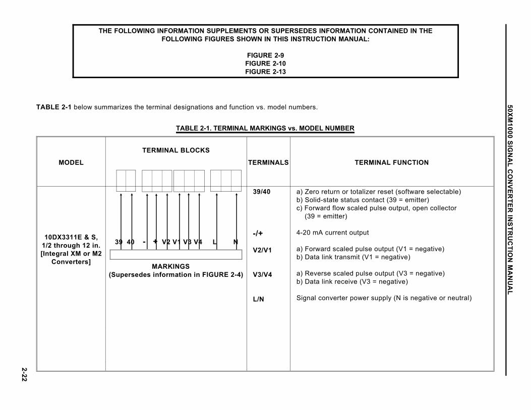
THE FOLLOWING INFORMATION SUPPLEMENTS OR SUPERSEDES INFORMATION CONTAINED IN THEFOLLOWING FIGURES SHOWN IN THIS INSTRUCTION MANUAL:
FIGURE 2-9FIGURE 2-10FIGURE 2-13
TABLE 2-1 below summarizes the terminal designations and function vs. model numbers.
TABLE 2-1. TERMINAL MARKINGS vs. MODEL NUMBER
MODEL
TERMINAL BLOCKS
TERMINALS TERMINAL FUNCTION
10DX3311E & S,1/2 through 12 in.[Integral XM or M2
Converters]
39 40 - + V2 V1 V3 V4 L N
MARKINGS (Supersedes information in FIGURE 2-4)
39/40
-/+
V2/V1
V3/V4
L/N
a) Zero return or totalizer reset (software selectable)b) Solid-state status contact (39 = emitter)c) Forward flow scaled pulse output, open collector (39 = emitter)
4-20 mA current output
a) Forward scaled pulse output (V1 = negative)b) Data link transmit (V1 = negative)
a) Reverse scaled pulse output (V3 = negative)b) Data link receive (V3 = negative)
Signal converter power supply (N is negative or neutral)
2-22
50XM1000 SIG
NA
L CO
NVER
TER IN
STRU
CTIO
N M
AN
UA
L
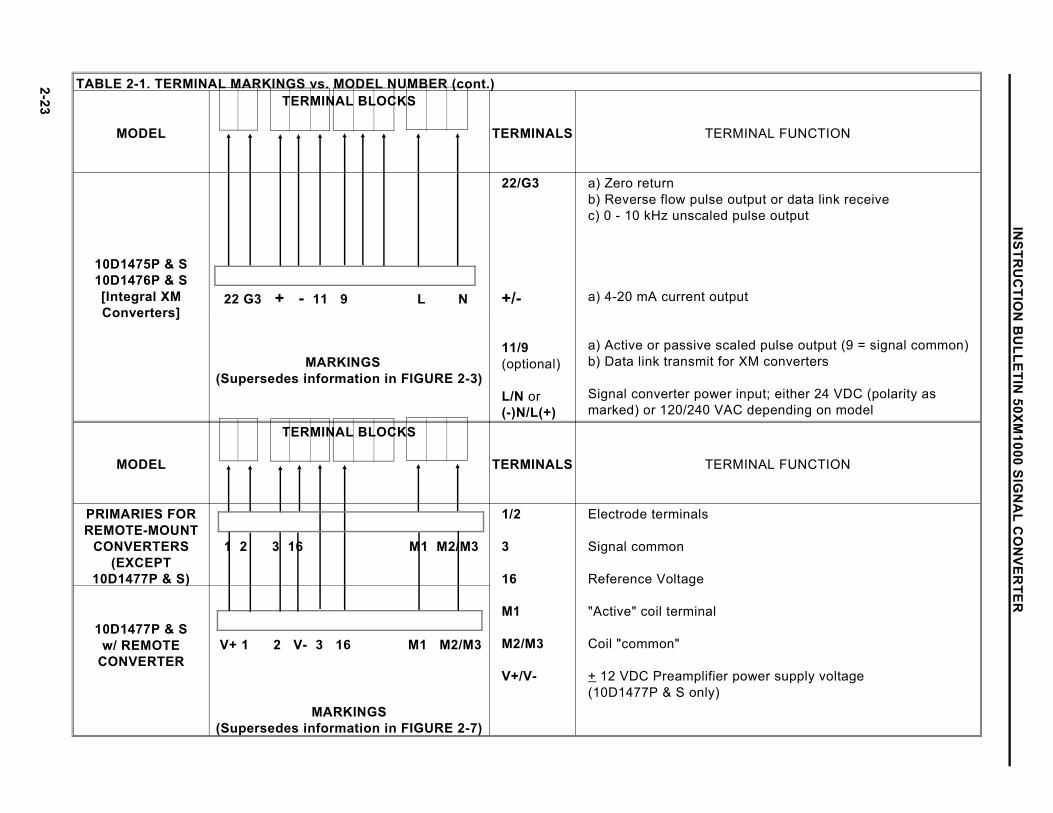
TABLE 2-1. TERMINAL MARKINGS vs. MODEL NUMBER (cont.)
MODEL
TERMINAL BLOCKS
TERMINALS TERMINAL FUNCTION
10D1475P & S10D1476P & S[Integral XMConverters]
22 G3 + - 11 9 L N
22/G3
+/-
11/9(optional)
L/N or(-)N/L(+)
a) Zero returnb) Reverse flow pulse output or data link receivec) 0 - 10 kHz unscaled pulse output
a) 4-20 mA current output
a) Active or passive scaled pulse output (9 = signal common)b) Data link transmit for XM converters
Signal converter power input; either 24 VDC (polarity asmarked) or 120/240 VAC depending on model
MARKINGS (Supersedes information in FIGURE 2-3)
MODEL
TERMINAL BLOCKS
TERMINALS TERMINAL FUNCTION
PRIMARIES FORREMOTE-MOUNT
CONVERTERS(EXCEPT
10D1477P & S)
1 2 3 16 M1 M2/M3
1/2
3
16
M1
M2/M3
V+/V-
Electrode terminals
Signal common
Reference Voltage
"Active" coil terminal
Coil "common"
+ 12 VDC Preamplifier power supply voltage(10D1477P & S only)
10D1477P & Sw/ REMOTE
CONVERTER V+ 1 2 V- 3 16 M1 M2/M3
MARKINGS(Supersedes information in FIGURE 2-7)
2-23
INSTR
UC
TION
BU
LLETIN 50XM
1000 SIGN
AL C
ON
VERTER
3.0 START-UP AND OPERATION
3.1 Start-Up
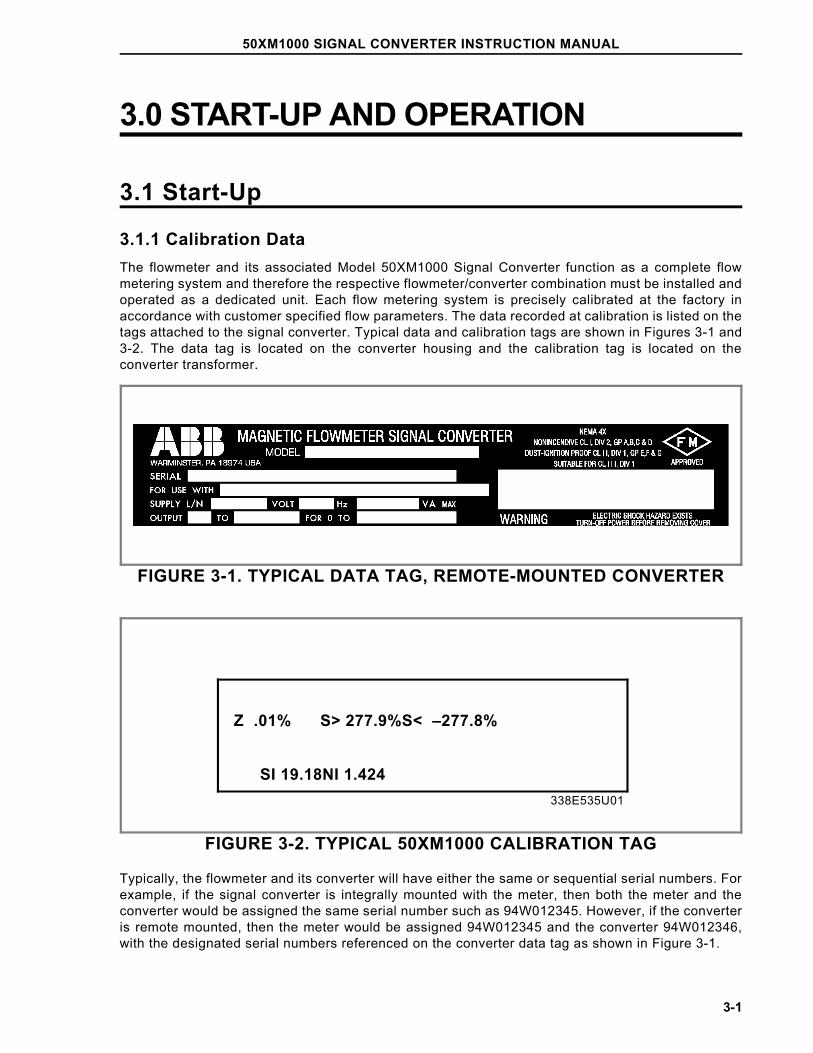
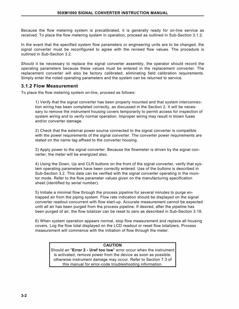
3.1.1 Calibration DataThe flowmeter and its associated Model 50XM1000 Signal Converter function as a complete flowmetering system and therefore the respective flowmeter/converter combination must be installed andoperated as a dedicated unit. Each flow metering system is precisely calibrated at the factory inaccordance with customer specified flow parameters. The data recorded at calibration is listed on thetags attached to the signal converter. Typical data and calibration tags are shown in Figures 3-1 and3-2. The data tag is located on the converter housing and the calibration tag is located on theconverter transformer.
FIGURE 3-1. TYPICAL DATA TAG, REMOTE-MOUNTED CONVERTER
FIGURE 3-2. TYPICAL 50XM1000 CALIBRATION TAG
Typically, the flowmeter and its converter will have either the same or sequential serial numbers. Forexample, if the signal converter is integrally mounted with the meter, then both the meter and theconverter would be assigned the same serial number such as 94W012345. However, if the converteris remote mounted, then the meter would be assigned 94W012345 and the converter 94W012346,with the designated serial numbers referenced on the converter data tag as shown in Figure 3-1.
Z .01% S> 277.9%S< –277.8%
SI 19.18NI 1.424338E535U01
50XM1000 SIGNAL CONVERTER INSTRUCTION MANUAL
3-1
Because the flow metering system is precalibrated, it is generally ready for on-line service asreceived. To place the flow metering system in operation, proceed as outlined in Sub-Section 3.1.2.
In the event that the specified system flow parameters or engineering units are to be changed, thesignal converter must be reconfigured to agree with the revised flow values. The procedure isoutlined in Sub-Section 3.2.
Should it be necessary to replace the signal converter assembly, the operator should record theoperating parameters because these values must be entered in the replacement converter. Thereplacement converter will also be factory calibrated, eliminating field calibration requirements.Simply enter the noted operating parameters and the system can be returned to service.
3.1.2 Flow MeasurementTo place the flow metering system on-line, proceed as follows:
1) Verify that the signal converter has been properly mounted and that system interconnec-tion wiring has been completed correctly, as discussed in the Section 2. It will be neces-sary to remove the instrument housing covers temporarily to permit access for inspection ofsystem wiring and to verify normal operation. Improper wiring may result in blown fusesand/or converter damage.
2) Check that the external power source connected to the signal converter is compatiblewith the power requirements of the signal converter. The converter power requirements arestated on the name tag affixed to the converter housing.
3) Apply power to the signal converter. Because the flowmeter is driven by the signal con-verter, the meter will be energized also.
4) Using the Down, Up and CLR buttons on the front of the signal converter, verify that sys-tem operating parameters have been correctly entered. Use of the buttons is described inSub-Section 3.2. This data can be verified with the signal converter operating in the moni-tor mode. Refer to the flow parameter values given on the manufacturing specificationsheet (identified by serial number).
5) Initiate a minimal flow through the process pipeline for several minutes to purge en-trapped air from the piping system. Flow rate indication should be displayed on the signalconverter readout concurrent with flow start-up. Accurate measurement cannot be expecteduntil all air has been purged from the process pipeline. If desired, after the pipeline hasbeen purged of air, the flow totalizer can be reset to zero as described in Sub-Section 3.18.
6) When system operation appears normal, stop flow measurement and replace all housingcovers. Log the flow total displayed on the LCD readout or reset flow totalizers. Processmeasurement will commence with the initiation of flow through the meter.
CAUTIONShould an "Error 2 - Uref too low" error occur when the instrument
is activated, remove power from the device as soon as possible,otherwise instrument damage may occur. Refer to Section 7.3 of
this manual for error-code troubleshooting information.
50XM1000 SIGNAL CONVERTER INSTRUCTION MANUAL
3-2
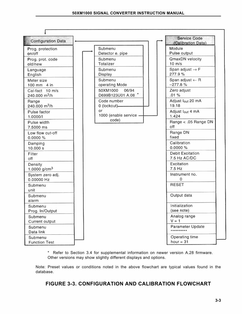
Note: Preset values or conditions noted in the above flowchart are typical values found in thedatabase.
FIGURE 3-3. CONFIGURATION AND CALIBRATION FLOWCHART
*
* Refer to Section 3.4 for supplemental information on newer version A.28 firmware.Other versions may show slightly different displays and options.
50XM1000 SIGNAL CONVERTER INSTRUCTION MANUAL
3-3
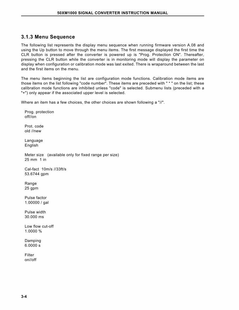
3.1.3 Menu SequenceThe following list represents the display menu sequence when running firmware version A.08 andusing the Up button to move through the menu items. The first message displayed the first time theCLR button is pressed after the converter is powered up is "Prog. Protection ON". Thereafter,pressing the CLR button while the converter is in monitoring mode will display the parameter ondisplay when configuration or calibration mode was last exited. There is wraparound between the lastand the first items on the menu.
The menu items beginning the list are configuration mode functions. Calibration mode items arethose items on the list following "code number". These items are preceded with " * " on the list; thesecalibration mode functions are inhibited unless "code" is selected. Submenu lists (preceded with a"+") only appear if the associated upper level is selected.
Where an item has a few choices, the other choices are shown following a "//".
Prog. protection off//on
Prot. code old //new
Language English
Meter size (available only for fixed range per size) 25 mm 1 in
Cal-fact 10m/s //33ft/s 53.6744 gpm
Range 25 gpm
Pulse factor 1.00000 / gal
Pulse width 30.000 ms
Low flow cut-off 1.0000 %
Damping 6.0000 s
Filter on//off
50XM1000 SIGNAL CONVERTER INSTRUCTION MANUAL
3-4
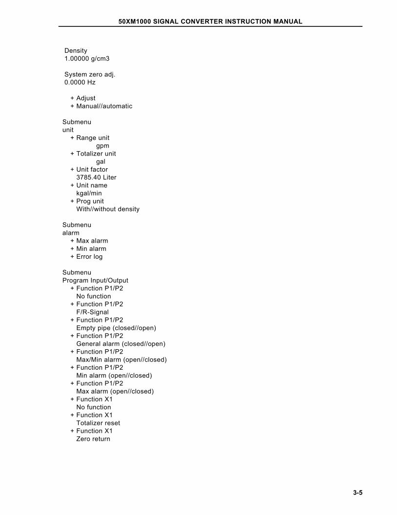
Density 1.00000 g/cm3
System zero adj. 0.0000 Hz
+ Adjust + Manual//automatic
Submenu unit + Range unit gpm + Totalizer unit gal + Unit factor 3785.40 Liter + Unit name kgal/min + Prog unit With//without density
Submenu alarm + Max alarm + Min alarm + Error log
Submenu Program Input/Output + Function P1/P2 No function + Function P1/P2 F/R-Signal + Function P1/P2 Empty pipe (closed//open) + Function P1/P2 General alarm (closed//open) + Function P1/P2 Max/Min alarm (open//closed) + Function P1/P2 Min alarm (open//closed) + Function P1/P2 Max alarm (open//closed) + Function X1 No function + Function X1 Totalizer reset + Function X1 Zero return
50XM1000 SIGNAL CONVERTER INSTRUCTION MANUAL
3-5
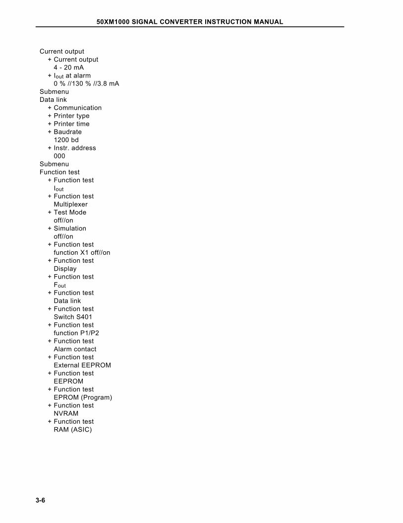
Current output + Current output 4 - 20 mA + Iout at alarm 0 % //130 % //3.8 mA Submenu Data link + Communication + Printer type + Printer time + Baudrate 1200 bd + Instr. address 000 Submenu Function test + Function test Iout + Function test Multiplexer + Test Mode off//on + Simulation off//on + Function test function X1 off//on + Function test Display + Function test Fout + Function test Data link + Function test Switch S401 + Function test function P1/P2 + Function test Alarm contact + Function test External EEPROM + Function test EEPROM + Function test EPROM (Program) + Function test NVRAM + Function test RAM (ASIC)
50XM1000 SIGNAL CONVERTER INSTRUCTION MANUAL
3-6
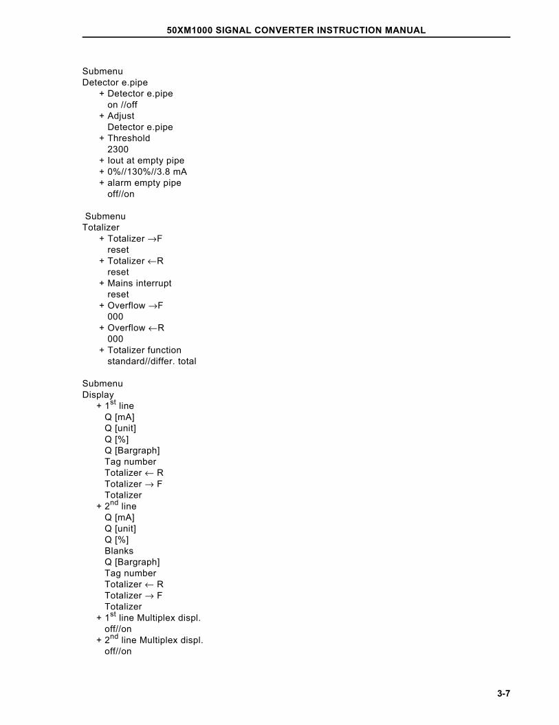
SubmenuDetector e.pipe + Detector e.pipe on //off + Adjust Detector e.pipe + Threshold 2300 + Iout at empty pipe + 0%//130%//3.8 mA + alarm empty pipe off//on
SubmenuTotalizer + Totalizer →F reset + Totalizer ←R reset + Mains interrupt reset + Overflow →F 000 + Overflow ←R 000 + Totalizer function standard//differ. total
SubmenuDisplay + 1st line Q [mA] Q [unit] Q [%] Q [Bargraph] Tag number Totalizer ← R Totalizer → F Totalizer + 2nd line Q [mA] Q [unit] Q [%] Blanks Q [Bargraph] Tag number Totalizer ← R Totalizer → F Totalizer + 1st line Multiplex displ. off//on + 2nd line Multiplex displ. off//on
50XM1000 SIGNAL CONVERTER INSTRUCTION MANUAL
3-7
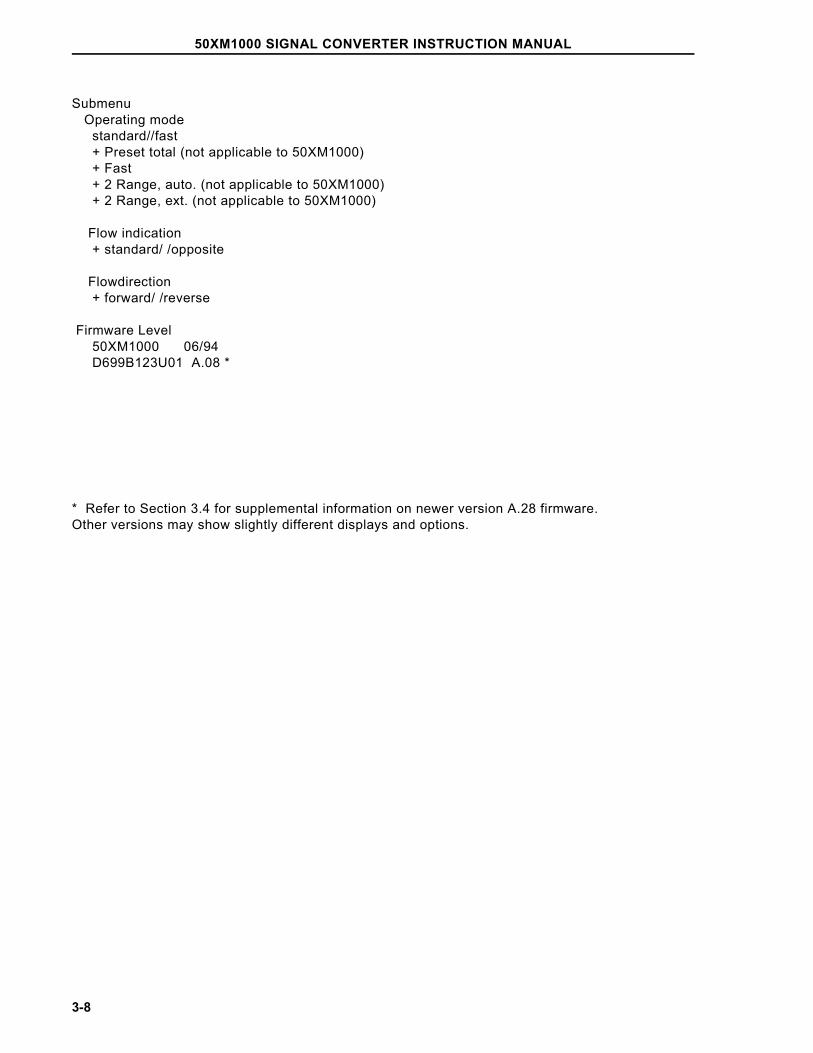
Submenu Operating mode standard//fast + Preset total (not applicable to 50XM1000) + Fast + 2 Range, auto. (not applicable to 50XM1000) + 2 Range, ext. (not applicable to 50XM1000)
Flow indication + standard/ /opposite
Flowdirection + forward/ /reverse
Firmware Level 50XM1000 06/94 D699B123U01 A.08 *
* Refer to Section 3.4 for supplemental information on newer version A.28 firmware.Other versions may show slightly different displays and options.
50XM1000 SIGNAL CONVERTER INSTRUCTION MANUAL
3-8
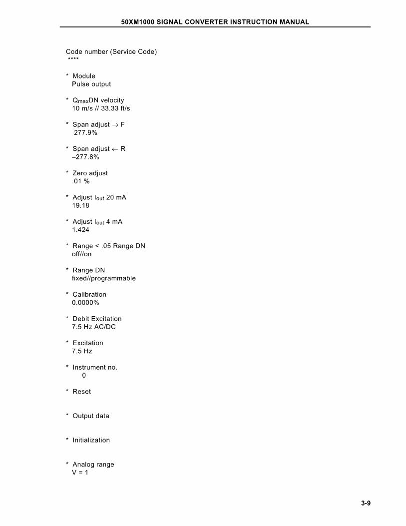
Code number (Service Code) ****
* Module Pulse output
* QmaxDN velocity 10 m/s // 33.33 ft/s
* Span adjust → F 277.9%
* Span adjust ← R –277.8%
* Zero adjust .01 %
* Adjust Iout 20 mA 19.18
* Adjust Iout 4 mA 1.424
* Range < .05 Range DN off//on
* Range DN fixed//programmable
* Calibration 0.0000%
* Debit Excitation 7.5 Hz AC/DC
* Excitation 7.5 Hz
* Instrument no. 0
* Reset * Output data
* Initialization
* Analog range V = 1
50XM1000 SIGNAL CONVERTER INSTRUCTION MANUAL
3-9

* Parameter Update ********
* Operating time hour = 31
50XM1000 SIGNAL CONVERTER INSTRUCTION MANUAL
3-10
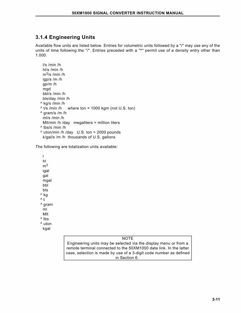
3.1.4 Engineering UnitsAvailable flow units are listed below. Entries for volumetric units followed by a "/" may use any of theunits of time following the "/". Entries preceded with a "^" permit use of a density entry other than1.000.
l/s /min /h hl/s /min /h m3/s /min /h igp/s /m /h gp/m /h mgd bbl/s /min /h bls/day /min /h ^ kg/s /min /h ^ t/s /min /h where ton = 1000 kgm (not U.S. ton) ^ gram/s /m /h ml/s /min /h Mlt/min /h /day megaliters = million liters ^ lbs/s /min /h ^ uton/min /h /day U.S. ton = 2000 pounds k/gal/s /m /h thousands of U.S. gallons
The following are totalization units available:
l hl m3
igal gal mgal bbl bls ^ kg ^ t ^ gram ml Mlt ^ lbs ^ uton kgal
NOTEEngineering units may be selected via the display menu or from aremote terminal connected to the 50XM1000 data link. In the lattercase, selection is made by use of a 3-digit code number as defined
in Section 6.
50XM1000 SIGNAL CONVERTER INSTRUCTION MANUAL
3-11
3.2 Configuration Procedure
The unit has been pre-configured at the factory per the specifications given at the time the order wasplaced. However, parameters can be changed using the procedure described in this section. Notethat the firmware version described in this bulletin is D699B123U01, A.08 (refer to Section 3.4 forsupplemental information on newer versions A.28 Standard and X.21 HART Protocol firmware); otherversions may show slightly different displays and options.
CAUTIONDo not power the unit with the terminals M1 and M3 connected with-
out also connecting terminals 3 and 16. Fuse failure and possible converter damage will result.
NOTEReplacement fuses must be the same as the original type suppliedwith the converter (i.e., 5x20 mm "T" type), LITTELFUSE type 218.
Other type fuses may blow as power is applied.
NOTEAdditional configuration information and a typical Test Wiring Dia-
gram are provided in Section 5.
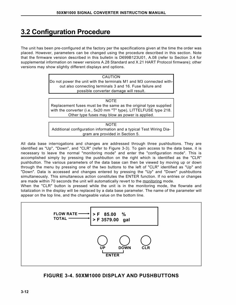
All data base interrogations and changes are addressed through three pushbuttons. They areidentified as "Up", "Down", and "CLR" (refer to Figure 3-3). To gain access to the data base, it isnecessary to leave the normal "monitoring mode" and enter the "configuration mode". This isaccomplished simply by pressing the pushbutton on the right which is identified as the "CLR"pushbutton. The various parameters of the data base can then be viewed by moving up or downthrough the menu by pressing one of the two buttons to the left of "CLR" identified as "Up" and"Down". Data is accessed and changes entered by pressing the "Up" and "Down" pushbuttonssimultaneously. This simultaneous action constitutes the ENTER function. If no entries or changesare made within 70 seconds the unit will automatically revert to the monitoring mode.When the "CLR" button is pressed while the unit is in the monitoring mode, the flowrate andtotalization in the display will be replaced by a data base parameter. The name of the parameter willappear on the top line, and the changeable value on the bottom line.
FIGURE 3-4. 50XM1000 DISPLAY AND PUSHBUTTONS
FLOW RATETOTAL
UP DOWN CLR
ENTER
> F 85.00 % > F 3579.00 gal
50XM1000 SIGNAL CONVERTER INSTRUCTION MANUAL
3-12
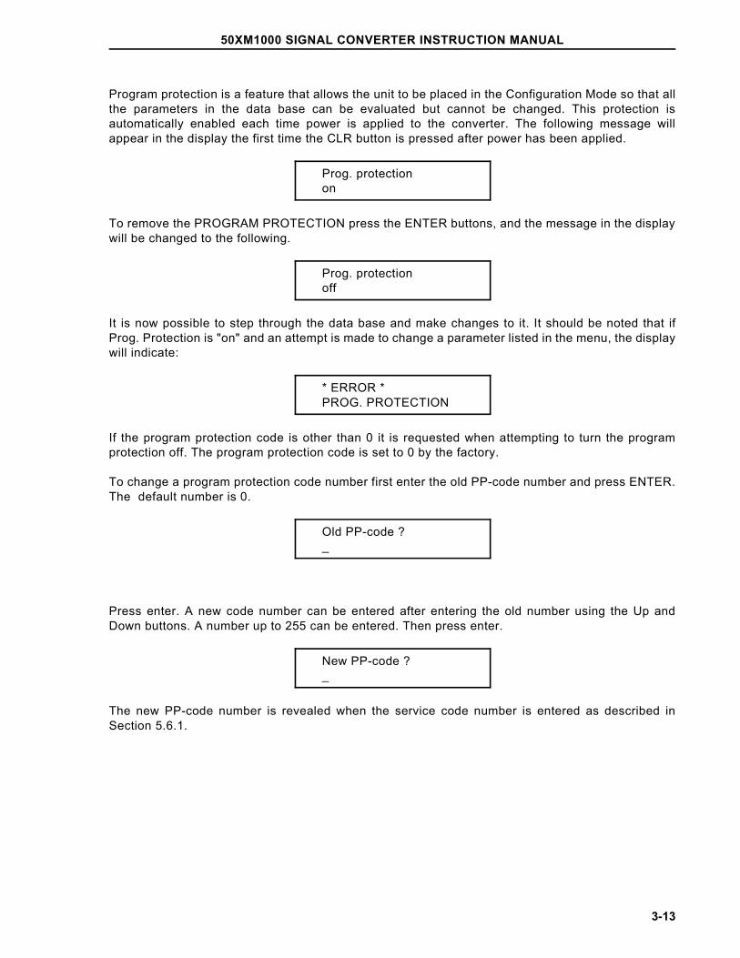
Program protection is a feature that allows the unit to be placed in the Configuration Mode so that allthe parameters in the data base can be evaluated but cannot be changed. This protection isautomatically enabled each time power is applied to the converter. The following message willappear in the display the first time the CLR button is pressed after power has been applied.
Prog. protectionon
To remove the PROGRAM PROTECTION press the ENTER buttons, and the message in the displaywill be changed to the following.
Prog. protectionoff
It is now possible to step through the data base and make changes to it. It should be noted that ifProg. Protection is "on" and an attempt is made to change a parameter listed in the menu, the displaywill indicate:
* ERROR *PROG. PROTECTION
If the program protection code is other than 0 it is requested when attempting to turn the programprotection off. The program protection code is set to 0 by the factory.
To change a program protection code number first enter the old PP-code number and press ENTER.The default number is 0.
Old PP-code ?_
Press enter. A new code number can be entered after entering the old number using the Up andDown buttons. A number up to 255 can be entered. Then press enter.
New PP-code ?_
The new PP-code number is revealed when the service code number is entered as described inSection 5.6.1.
50XM1000 SIGNAL CONVERTER INSTRUCTION MANUAL
3-13
There are two ways to make changes to the data base. One is by entering numeric values, and theother is by making a selection from the menu. Numbers are entered by pressing the Up and Downbuttons. The Up button is used to select numbers 0 through 9, decimal point, minus sign, or a blankspace. The Down button is used to move to the next digit.
An overview of the menu sequence is provided in Sub-Secton 3.1.3 and Figure 3-3.
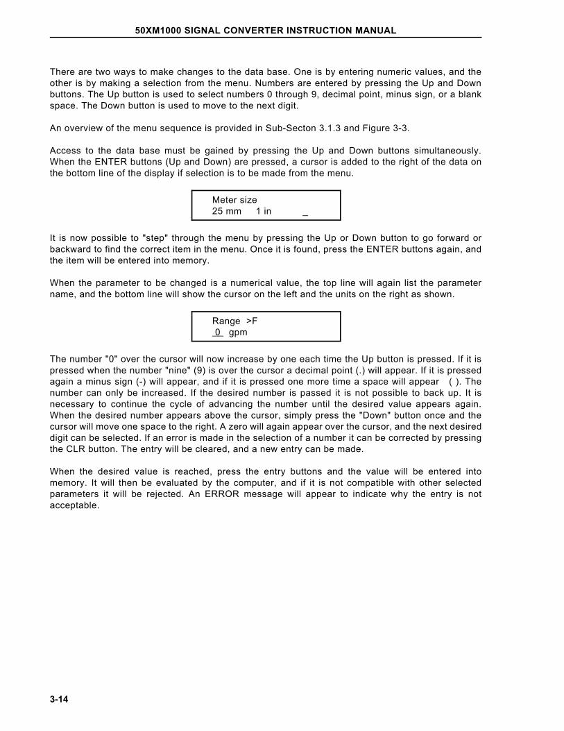
Access to the data base must be gained by pressing the Up and Down buttons simultaneously.When the ENTER buttons (Up and Down) are pressed, a cursor is added to the right of the data onthe bottom line of the display if selection is to be made from the menu.
Meter size 25 mm 1 in _
It is now possible to "step" through the menu by pressing the Up or Down button to go forward orbackward to find the correct item in the menu. Once it is found, press the ENTER buttons again, andthe item will be entered into memory.
When the parameter to be changed is a numerical value, the top line will again list the parametername, and the bottom line will show the cursor on the left and the units on the right as shown.
Range >F 0 gpm
The number "0" over the cursor will now increase by one each time the Up button is pressed. If it ispressed when the number "nine" (9) is over the cursor a decimal point (.) will appear. If it is pressedagain a minus sign (-) will appear, and if it is pressed one more time a space will appear ( ). Thenumber can only be increased. If the desired number is passed it is not possible to back up. It isnecessary to continue the cycle of advancing the number until the desired value appears again.When the desired number appears above the cursor, simply press the "Down" button once and thecursor will move one space to the right. A zero will again appear over the cursor, and the next desireddigit can be selected. If an error is made in the selection of a number it can be corrected by pressingthe CLR button. The entry will be cleared, and a new entry can be made.
When the desired value is reached, press the entry buttons and the value will be entered intomemory. It will then be evaluated by the computer, and if it is not compatible with other selectedparameters it will be rejected. An ERROR message will appear to indicate why the entry is notacceptable.
50XM1000 SIGNAL CONVERTER INSTRUCTION MANUAL
3-14
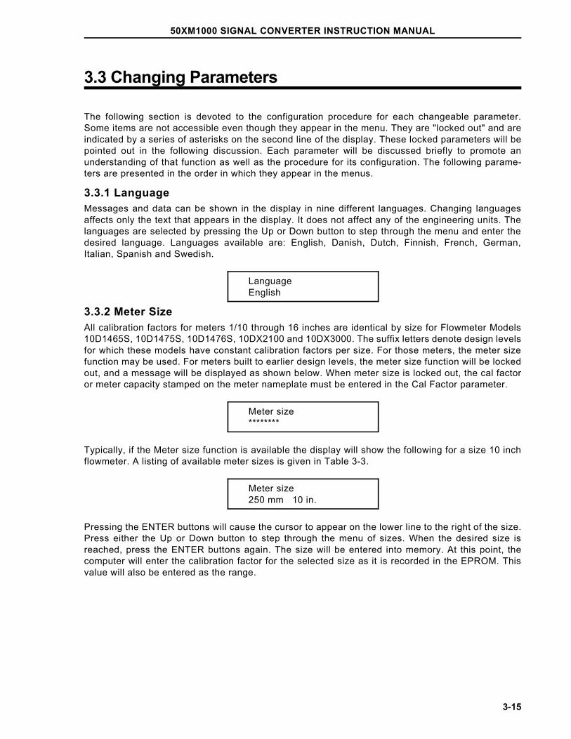
3.3 Changing Parameters
The following section is devoted to the configuration procedure for each changeable parameter.Some items are not accessible even though they appear in the menu. They are "locked out" and areindicated by a series of asterisks on the second line of the display. These locked parameters will bepointed out in the following discussion. Each parameter will be discussed briefly to promote anunderstanding of that function as well as the procedure for its configuration. The following parame-ters are presented in the order in which they appear in the menus.
3.3.1 Language Messages and data can be shown in the display in nine different languages. Changing languagesaffects only the text that appears in the display. It does not affect any of the engineering units. Thelanguages are selected by pressing the Up or Down button to step through the menu and enter thedesired language. Languages available are: English, Danish, Dutch, Finnish, French, German,Italian, Spanish and Swedish.
LanguageEnglish
3.3.2 Meter SizeAll calibration factors for meters 1/10 through 16 inches are identical by size for Flowmeter Models10D1465S, 10D1475S, 10D1476S, 10DX2100 and 10DX3000. The suffix letters denote design levelsfor which these models have constant calibration factors per size. For those meters, the meter sizefunction may be used. For meters built to earlier design levels, the meter size function will be lockedout, and a message will be displayed as shown below. When meter size is locked out, the cal factoror meter capacity stamped on the meter nameplate must be entered in the Cal Factor parameter.
Meter size********
Typically, if the Meter size function is available the display will show the following for a size 10 inchflowmeter. A listing of available meter sizes is given in Table 3-3.
Meter size250 mm 10 in.
Pressing the ENTER buttons will cause the cursor to appear on the lower line to the right of the size.Press either the Up or Down button to step through the menu of sizes. When the desired size isreached, press the ENTER buttons again. The size will be entered into memory. At this point, thecomputer will enter the calibration factor for the selected size as it is recorded in the EPROM. Thisvalue will also be entered as the range.
50XM1000 SIGNAL CONVERTER INSTRUCTION MANUAL
3-15
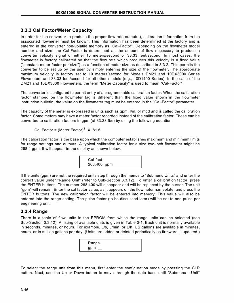
3.3.3 Cal Factor/Meter CapacityIn order for the converter to produce the proper flow rate output(s), calibration information from theassociated flowmeter must be known. This information has been determined at the factory and isentered in the converter non-volatile memory as "Cal-Factor". Depending on the flowmeter modelnumber and size, the Cal-Factor is determined as the amount of flow necessary to produce aconverter velocity signal of either 10 meters/second or 33.33 feet/second. In most cases, theflowmeter is factory calibrated so that the flow rate which produces this velocity is a fixed value("constant meter factor per size") as a function of meter size as described in 3.3.2. This permits theconverter to be set up by the user by simply entering the size of the flowmeter. The appropriatemaximum velocity is factory set to 10 meters/second for Models DM21 and 10DX3000 SeriesFlowmeters and 33.33 feet/second for all other models (e.g., 10D1400 Series). In the case of theDM21 and 10DX3000 Flowmeters, the term "Meter Capacity" is used to mean "Cal-Factor".
The converter is configured to permit entry of a programmable calibration factor. When the calibrationfactor stamped on the flowmeter tag is different than the fixed value shown in the flowmeterinstruction bulletin, the value on the flowmeter tag must be entered in the "Cal-Factor" parameter.
The capacity of the meter is expressed in units such as gpm, l/m, or mgd and is called the calibrationfactor. Some meters may have a meter factor recorded instead of the calibration factor. These can beconverted to calibration factors in gpm (at 33.33 ft/s) by using the following equation:
Cal Factor = (Meter Factor)2 X 81.6
The calibration factor is the base upon which the computer establishes maximum and minimum limitsfor range settings and outputs. A typical calibration factor for a size two-inch flowmeter might be268.4 gpm. It will appear in the display as shown below.
Cal-fact268.400 gpm
If the units (gpm) are not the required units step through the menus to "Submenu Units" and enter thecorrect value under "Range Unit" (refer to Sub-Section 3.3.12). To enter a calibration factor, pressthe ENTER buttons. The number 268.400 will disappear and will be replaced by the cursor. The unit"gpm" will remain. Enter the cal factor value, as it appears on the flowmeter nameplate, and press theENTER buttons. The new calibration factor will be entered into memory. This value will also beentered into the range setting. The pulse factor (to be discussed later) will be set to one pulse perengineering unit.
3.3.4 RangeThere is a table of flow units in the EPROM from which the range units can be selected (seeSub-Section 3.3.12). A listing of available units is given in Table 3-1. Each unit is normally availablein seconds, minutes, or hours. For example, L/s, L/min, or L/h. US gallons are available in minutes,hours, or in million gallons per day. (Units are added or deleted periodically as firmware is updated.)
Range gpm
To select the range unit from this menu, first enter the configuration mode by pressing the CLRbutton. Next, use the Up or Down button to move through the data base until "Submenu - Unit"
50XM1000 SIGNAL CONVERTER INSTRUCTION MANUAL
3-16
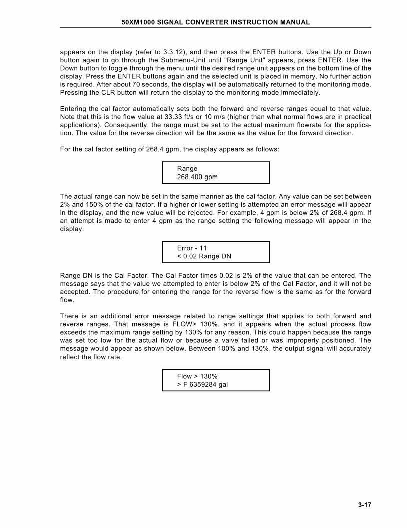
appears on the display (refer to 3.3.12), and then press the ENTER buttons. Use the Up or Downbutton again to go through the Submenu-Unit until "Range Unit" appears, press ENTER. Use theDown button to toggle through the menu until the desired range unit appears on the bottom line of thedisplay. Press the ENTER buttons again and the selected unit is placed in memory. No further actionis required. After about 70 seconds, the display will be automatically returned to the monitoring mode.Pressing the CLR button will return the display to the monitoring mode immediately.
Entering the cal factor automatically sets both the forward and reverse ranges equal to that value.Note that this is the flow value at 33.33 ft/s or 10 m/s (higher than what normal flows are in practicalapplications). Consequently, the range must be set to the actual maximum flowrate for the applica-tion. The value for the reverse direction will be the same as the value for the forward direction.
For the cal factor setting of 268.4 gpm, the display appears as follows:
Range 268.400 gpm
The actual range can now be set in the same manner as the cal factor. Any value can be set between2% and 150% of the cal factor. If a higher or lower setting is attempted an error message will appearin the display, and the new value will be rejected. For example, 4 gpm is below 2% of 268.4 gpm. Ifan attempt is made to enter 4 gpm as the range setting the following message will appear in thedisplay.
Error - 11< 0.02 Range DN
Range DN is the Cal Factor. The Cal Factor times 0.02 is 2% of the value that can be entered. Themessage says that the value we attempted to enter is below 2% of the Cal Factor, and it will not beaccepted. The procedure for entering the range for the reverse flow is the same as for the forwardflow.
There is an additional error message related to range settings that applies to both forward andreverse ranges. That message is FLOW> 130%, and it appears when the actual process flowexceeds the maximum range setting by 130% for any reason. This could happen because the rangewas set too low for the actual flow or because a valve failed or was improperly positioned. Themessage would appear as shown below. Between 100% and 130%, the output signal will accuratelyreflect the flow rate.
Flow > 130%> F 6359284 gal
50XM1000 SIGNAL CONVERTER INSTRUCTION MANUAL
3-17
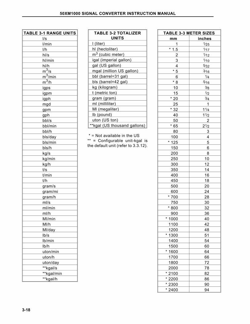
TABLE 3-1 RANGE UNITSl/sl/minl/hhl/shl/minhl/hm3/sm3/minm3/higpsigpmigphmgdgpmgphbbl/sbbl/minbbl/hbls/daybls/minbls/hkg/skg/minkg/ht/st/mint/hgram/sgram/migram/hml/sml/minml/hMI/minMl/hMl/daylb/slb/minlb/huton/minuton/huton/day**kgal/s**kgal/min**kgal/h
TABLE 3-2 TOTALIZERUNITS
l (liter)hl (hectoliter)m3 (cubic meter)igal (imperial gallon)gal (US gallon)mgal (million US gallon)bbl (barrel=31 gal)bls (barrel=42 gal)kg (kilogram)t (metric ton)gram (gram)ml (milliliter)Ml (megaliter)lb (pound)uton (US ton)
**kgal (US thousand gallons)
* = Not available in the US** = Configurable unit-kgal isthe default unit (refer to 3.3.12).
TABLE 3-3 METER SIZESmm inches
1 1⁄25* 1.5 1⁄17
2 1⁄123 1⁄104 5⁄32
* 5 3⁄166 1⁄4
* 8 5⁄1610 3⁄815 1⁄2
* 20 3⁄425 1
* 32 11⁄440 11⁄250 2
* 65 21⁄280 3
100 4* 125 5
150 6200 8250 10300 12350 14400 16450 18500 20600 24
* 700 28750 30
* 800 32900 36
* 1000 401100 421200 48
* 1300 511400 541500 60
* 1600 641700 661800 722000 78
* 2100 82* 2200 86* 2300 90* 2400 94
50XM1000 SIGNAL CONVERTER INSTRUCTION MANUAL
3-18
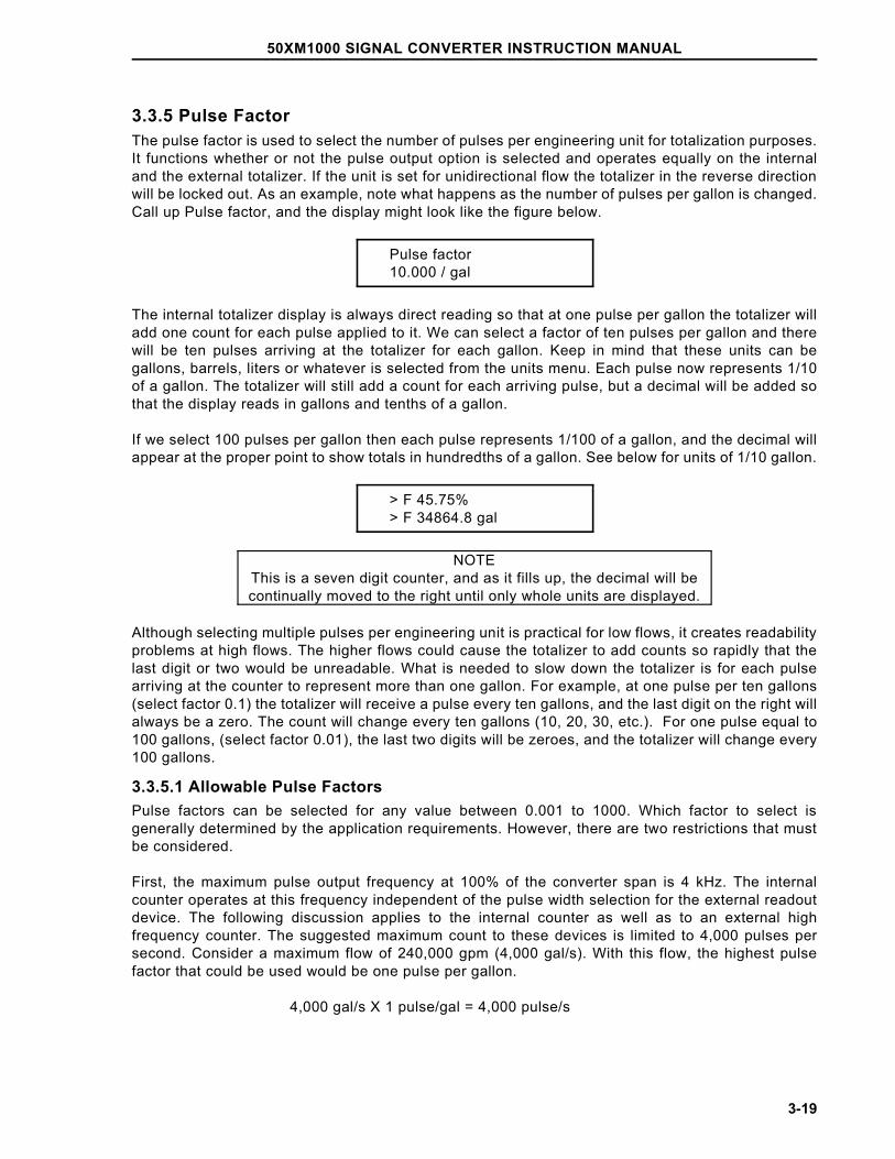
3.3.5 Pulse FactorThe pulse factor is used to select the number of pulses per engineering unit for totalization purposes.It functions whether or not the pulse output option is selected and operates equally on the internaland the external totalizer. If the unit is set for unidirectional flow the totalizer in the reverse directionwill be locked out. As an example, note what happens as the number of pulses per gallon is changed.Call up Pulse factor, and the display might look like the figure below.
Pulse factor 10.000 / gal
The internal totalizer display is always direct reading so that at one pulse per gallon the totalizer willadd one count for each pulse applied to it. We can select a factor of ten pulses per gallon and therewill be ten pulses arriving at the totalizer for each gallon. Keep in mind that these units can begallons, barrels, liters or whatever is selected from the units menu. Each pulse now represents 1/10of a gallon. The totalizer will still add a count for each arriving pulse, but a decimal will be added sothat the display reads in gallons and tenths of a gallon.
If we select 100 pulses per gallon then each pulse represents 1/100 of a gallon, and the decimal willappear at the proper point to show totals in hundredths of a gallon. See below for units of 1/10 gallon.
> F 45.75%> F 34864.8 gal
NOTEThis is a seven digit counter, and as it fills up, the decimal will becontinually moved to the right until only whole units are displayed.
Although selecting multiple pulses per engineering unit is practical for low flows, it creates readabilityproblems at high flows. The higher flows could cause the totalizer to add counts so rapidly that thelast digit or two would be unreadable. What is needed to slow down the totalizer is for each pulsearriving at the counter to represent more than one gallon. For example, at one pulse per ten gallons(select factor 0.1) the totalizer will receive a pulse every ten gallons, and the last digit on the right willalways be a zero. The count will change every ten gallons (10, 20, 30, etc.). For one pulse equal to100 gallons, (select factor 0.01), the last two digits will be zeroes, and the totalizer will change every100 gallons.
3.3.5.1 Allowable Pulse FactorsPulse factors can be selected for any value between 0.001 to 1000. Which factor to select isgenerally determined by the application requirements. However, there are two restrictions that mustbe considered.
First, the maximum pulse output frequency at 100% of the converter span is 4 kHz. The internalcounter operates at this frequency independent of the pulse width selection for the external readoutdevice. The following discussion applies to the internal counter as well as to an external highfrequency counter. The suggested maximum count to these devices is limited to 4,000 pulses persecond. Consider a maximum flow of 240,000 gpm (4,000 gal/s). With this flow, the highest pulsefactor that could be used would be one pulse per gallon.
4,000 gal/s X 1 pulse/gal = 4,000 pulse/s
50XM1000 SIGNAL CONVERTER INSTRUCTION MANUAL
3-19
However, the converter will normally function properly up to 130% of the range setting. This meansthat for a range setting of 4,000 gal/s (and 4000 pulses/s at 100%) a proper output signal will begenerated for flows up to 5,200 gal/s (4,000 X 1.3 = 5,200). The analog value at 130% of the rangesetting will be 24.8 mA dc. Although this condition is acceptable, it is not considered good practice.
Ideally, a pulse factor should be selected to keep the pulses to the counter within the 4,000 persecond limit. For example, if we apply a pulse factor of 0.1 to the above example then each pulse willrepresent 10 gallons, and the pulses at the counter will be within 4,000 per second.
4,000 gal/s X 1.3 X 0.1 pulse/gal = 520 pulses/s
Second, electromechanical counters typically require a pulse width of 30 milliseconds or more andare limited to about 15 counts (pulses) per second. They require time between pulses to complete themechanical operation of moving a wheel to its next count position. If there is not sufficient timebetween pulses to do this the counter will jam. A high pulse factor could create a condition where anexternal electromechanical counter would jam while the internal counter would continue to operate.Because the ERROR message is based upon 4 kHz (operating frequency of internal counter), therewould be no alert to signal this condition.
A conservative approach would assume a 50 millisecond on time and 50 milliseconds betweenpulses at maximum flow. This gives 100 milliseconds total time for each pulse or ten pulses persecond. Consider a flow of 750 gpm or 12.5 gal/s.
12.5 gal/s X 1 pulse/gal = 12.5 pulses/s
The converter can operate up to 130% of range setting!
12.5 gal/s X 1.3 X 1 pulse/sec = 16.25 pulses/s
This condition would not generate an ERROR message, but it could cause the electromechanicalcounter to jam. It would operate normally up to the maximum range setting, and as the flowapproached 130% of the range setting, the counter could jam. The internal counter would continue tocount.
3.3.5.2 Pulse Factor SummaryThe important thing to remember about pulse factor selection is that the high frequency output islimited to 4,000 counts per second and the external electromechanical devices are limited to about15 counts per second. Also, remember that the internal counter operates independently of the pulsewidth selection and the external counter. To select a pulse factor, convert flowrate to units persecond. Then multiply by 1.3 to determine flowrate at 130% of range setting. This cannot exceed5200 per second for high frequency devices or 15 counts per second for electromechanical counters.Select a pulse factor that will keep the counts within these limits.
CAUTIONThe sequence in which the range and pulse factor are selected areimportant. The range must be selected first and then the pulse fac-tor. If the pulse factor is selected first or is not reset when a range
change is made, the frequency to the totalizer could exceed the lim-its discussed above.
50XM1000 SIGNAL CONVERTER INSTRUCTION MANUAL
3-20
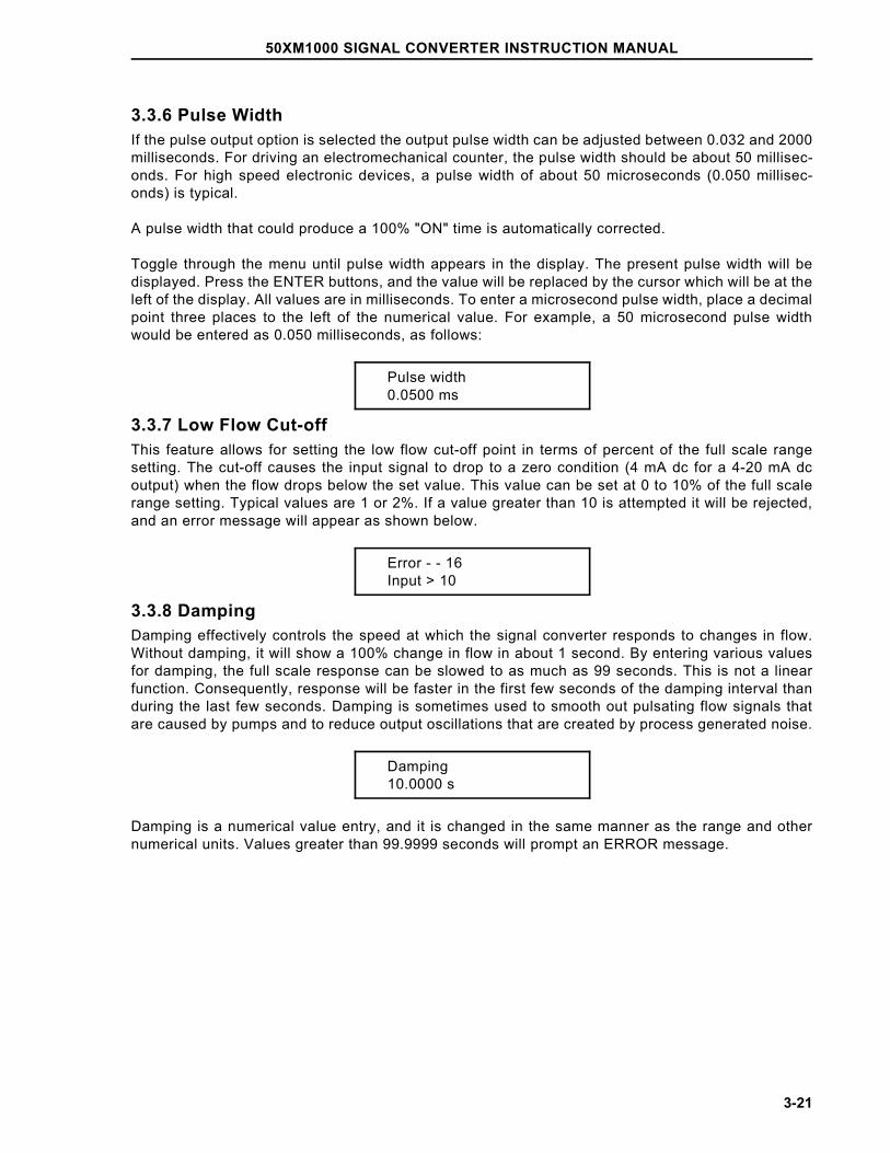
3.3.6 Pulse WidthIf the pulse output option is selected the output pulse width can be adjusted between 0.032 and 2000milliseconds. For driving an electromechanical counter, the pulse width should be about 50 millisec-onds. For high speed electronic devices, a pulse width of about 50 microseconds (0.050 millisec-onds) is typical.
A pulse width that could produce a 100% "ON" time is automatically corrected.
Toggle through the menu until pulse width appears in the display. The present pulse width will bedisplayed. Press the ENTER buttons, and the value will be replaced by the cursor which will be at theleft of the display. All values are in milliseconds. To enter a microsecond pulse width, place a decimalpoint three places to the left of the numerical value. For example, a 50 microsecond pulse widthwould be entered as 0.050 milliseconds, as follows:
Pulse width0.0500 ms
3.3.7 Low Flow Cut-offThis feature allows for setting the low flow cut-off point in terms of percent of the full scale rangesetting. The cut-off causes the input signal to drop to a zero condition (4 mA dc for a 4-20 mA dcoutput) when the flow drops below the set value. This value can be set at 0 to 10% of the full scalerange setting. Typical values are 1 or 2%. If a value greater than 10 is attempted it will be rejected,and an error message will appear as shown below.
Error - - 16Input > 10
3.3.8 DampingDamping effectively controls the speed at which the signal converter responds to changes in flow.Without damping, it will show a 100% change in flow in about 1 second. By entering various valuesfor damping, the full scale response can be slowed to as much as 99 seconds. This is not a linearfunction. Consequently, response will be faster in the first few seconds of the damping interval thanduring the last few seconds. Damping is sometimes used to smooth out pulsating flow signals thatare caused by pumps and to reduce output oscillations that are created by process generated noise.
Damping10.0000 s
Damping is a numerical value entry, and it is changed in the same manner as the range and othernumerical units. Values greater than 99.9999 seconds will prompt an ERROR message.
50XM1000 SIGNAL CONVERTER INSTRUCTION MANUAL
3-21
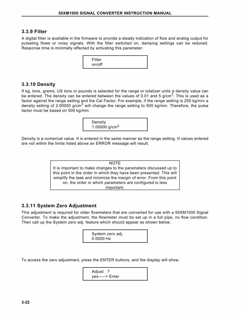
3.3.9 FilterA digital filter is available in the firmware to provide a steady indication of flow and analog output forpulsating flows or noisy signals. With the filter switched on, damping settings can be reduced.Response time is minimally effected by activating this parameter.
Filteron/off
3.3.10 DensityIf kg, tons, grams, US tons or pounds is selected for the range or totalizer units a density value canbe entered. The density can be entered between the values of 0.01 and 5 g/cm3. This is used as afactor against the range setting and the Cal Factor. For example, if the range setting is 250 kg/min adensity setting of 2.00000 g/cm3 will change the range setting to 500 kg/min. Therefore, the pulsefactor must be based on 500 kg/min.
Density1.00000 g/cm3
Density is a numerical value. It is entered in the same manner as the range setting. If values enteredare not within the limits listed above an ERROR message will result.
NOTEIt is important to make changes to the parameters discussed up tothis point in the order in which they have been presented. This willsimplify the task and minimize the margin of error. From this point
on, the order in which parameters are configured is lessimportant.
3.3.11 System Zero AdjustmentThis adjustment is required for older flowmeters that are converted for use with a 50XM1000 SignalConverter. To make the adjustment, the flowmeter must be set up in a full pipe, no flow condition.Then call up the System zero adj. feature which should appear as shown below.
System zero adj.0.0000 Hz
To access the zero adjustment, press the ENTER buttons, and the display will show:
Adjust ?yes-----> Enter
50XM1000 SIGNAL CONVERTER INSTRUCTION MANUAL
3-22
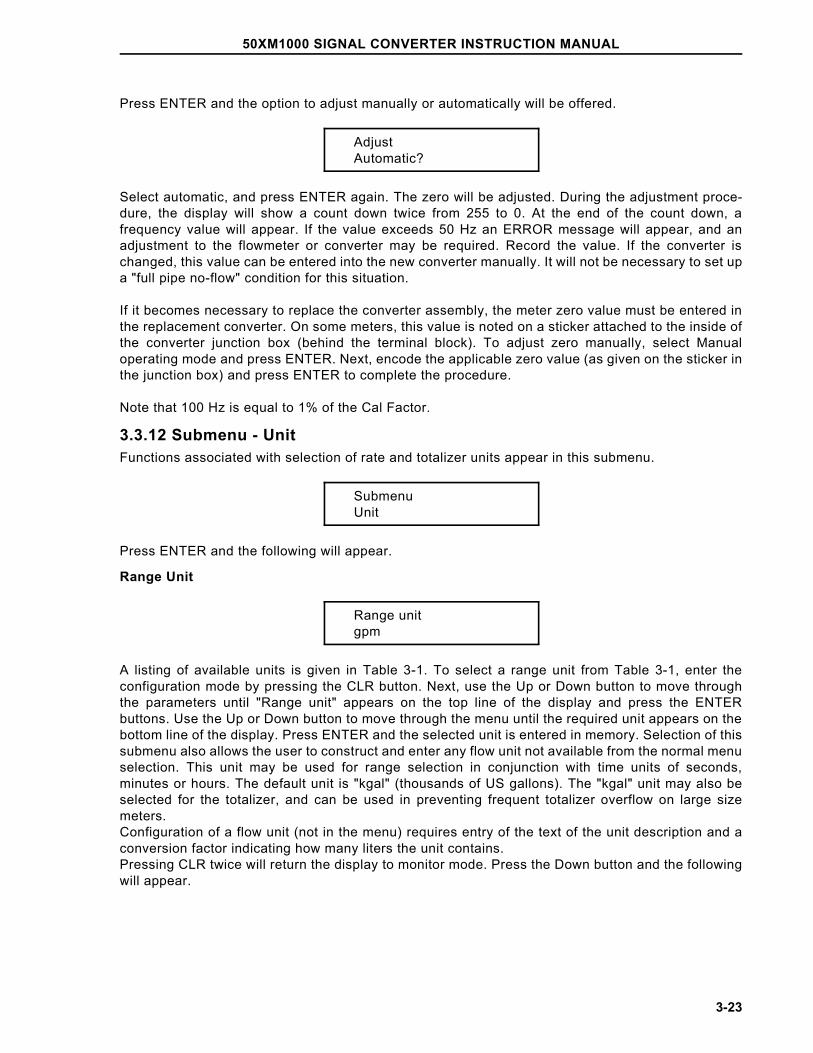
Press ENTER and the option to adjust manually or automatically will be offered.
AdjustAutomatic?
Select automatic, and press ENTER again. The zero will be adjusted. During the adjustment proce-dure, the display will show a count down twice from 255 to 0. At the end of the count down, afrequency value will appear. If the value exceeds 50 Hz an ERROR message will appear, and anadjustment to the flowmeter or converter may be required. Record the value. If the converter ischanged, this value can be entered into the new converter manually. It will not be necessary to set upa "full pipe no-flow" condition for this situation.
If it becomes necessary to replace the converter assembly, the meter zero value must be entered inthe replacement converter. On some meters, this value is noted on a sticker attached to the inside ofthe converter junction box (behind the terminal block). To adjust zero manually, select Manualoperating mode and press ENTER. Next, encode the applicable zero value (as given on the sticker inthe junction box) and press ENTER to complete the procedure.
Note that 100 Hz is equal to 1% of the Cal Factor.
3.3.12 Submenu - UnitFunctions associated with selection of rate and totalizer units appear in this submenu.
SubmenuUnit
Press ENTER and the following will appear.
Range Unit
Range unitgpm
A listing of available units is given in Table 3-1. To select a range unit from Table 3-1, enter theconfiguration mode by pressing the CLR button. Next, use the Up or Down button to move throughthe parameters until "Range unit" appears on the top line of the display and press the ENTERbuttons. Use the Up or Down button to move through the menu until the required unit appears on thebottom line of the display. Press ENTER and the selected unit is entered in memory. Selection of thissubmenu also allows the user to construct and enter any flow unit not available from the normal menuselection. This unit may be used for range selection in conjunction with time units of seconds,minutes or hours. The default unit is "kgal" (thousands of US gallons). The "kgal" unit may also beselected for the totalizer, and can be used in preventing frequent totalizer overflow on large sizemeters. Configuration of a flow unit (not in the menu) requires entry of the text of the unit description and aconversion factor indicating how many liters the unit contains.Pressing CLR twice will return the display to monitor mode. Press the Down button and the followingwill appear.
50XM1000 SIGNAL CONVERTER INSTRUCTION MANUAL
3-23
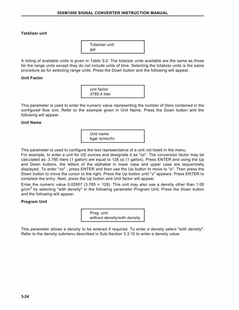
Totalizer unit
Totalizer unitgal
A listing of available units is given in Table 3-2. The totalizer units available are the same as thosefor the range units except they do not include units of time. Selecting the totalizer units is the sameprocedure as for selecting range units. Press the Down button and the following will appear.
Unit Factor
unit factor3785.4 liter
This parameter is used to enter the numeric value representing the number of liters contained in theconfigured flow unit. Refer to the example given in Unit Name. Press the Down button and thefollowing will appear.
Unit Name
Unit namekgal /s/min/hr
This parameter is used to configure the text representative of a unit not listed in the menu. For example, to enter a unit for US ounces and designate it as "oz". The conversion factor may becalculated as: 3.785 liters (1 gallon) are equal to 128 oz (1 gallon). Press ENTER and using the Upand Down buttons, the letters of the alphabet in lower case and upper case are sequentiallydisplayed. To enter "oz" , press ENTER and then use the Up button to move to "o". Then press theDown button to move the cursor to the right. Press the Up button until "z" appears. Press ENTER tocomplete the entry. Next, press the Up button and Unit factor will appear. Enter the numeric value 0.02957 (3.785 ÷ 128). This unit may also use a density other than 1.00g/cm3 by selecting "with density" in the following parameter Program Unit. Press the Down buttonand the following will appear.
Program Unit
Prog. unitwithout density/with density
This parameter allows a density to be entered if required. To enter a density select "with density".Refer to the density submenu described in Sub-Section 3.3.10 to enter a density value.
50XM1000 SIGNAL CONVERTER INSTRUCTION MANUAL
3-24
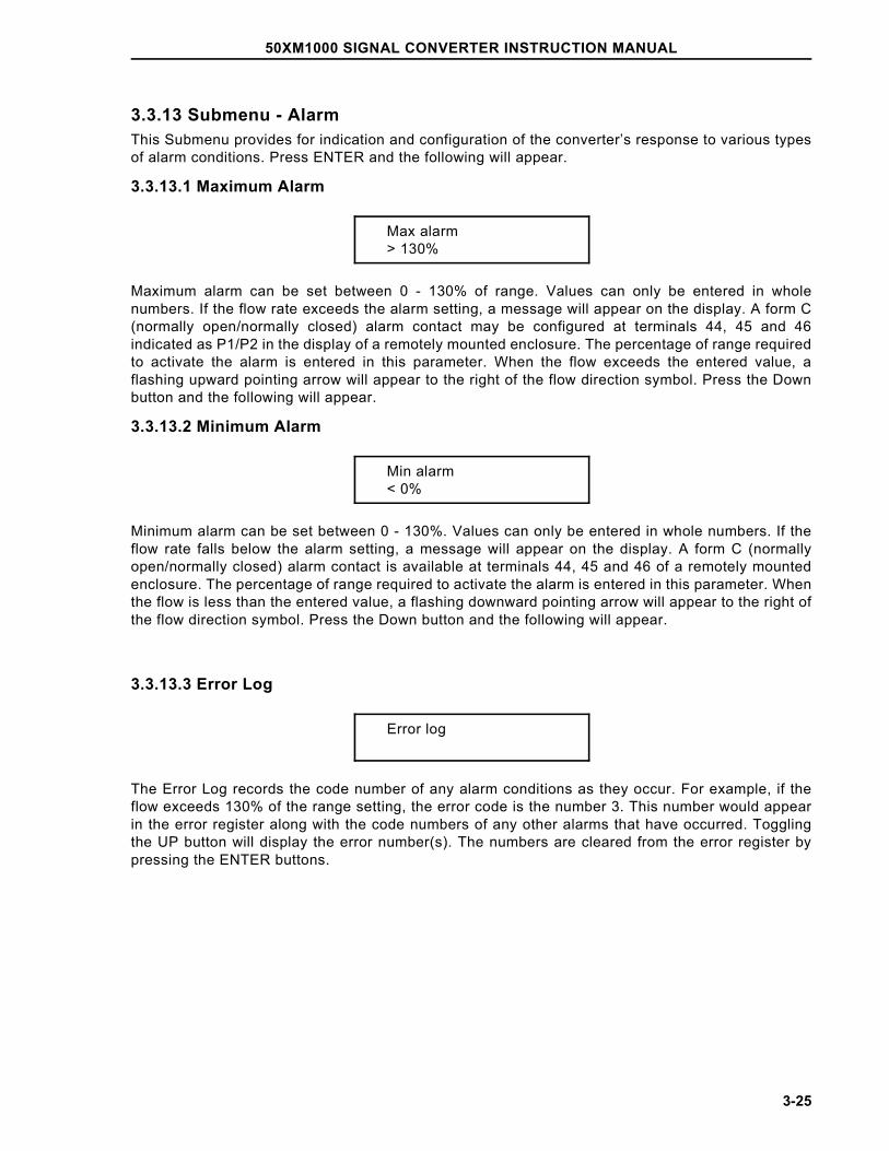
3.3.13 Submenu - AlarmThis Submenu provides for indication and configuration of the converter’s response to various typesof alarm conditions. Press ENTER and the following will appear.
3.3.13.1 Maximum Alarm
Max alarm> 130%
Maximum alarm can be set between 0 - 130% of range. Values can only be entered in wholenumbers. If the flow rate exceeds the alarm setting, a message will appear on the display. A form C(normally open/normally closed) alarm contact may be configured at terminals 44, 45 and 46indicated as P1/P2 in the display of a remotely mounted enclosure. The percentage of range requiredto activate the alarm is entered in this parameter. When the flow exceeds the entered value, aflashing upward pointing arrow will appear to the right of the flow direction symbol. Press the Downbutton and the following will appear.
3.3.13.2 Minimum Alarm
Min alarm< 0%
Minimum alarm can be set between 0 - 130%. Values can only be entered in whole numbers. If theflow rate falls below the alarm setting, a message will appear on the display. A form C (normallyopen/normally closed) alarm contact is available at terminals 44, 45 and 46 of a remotely mountedenclosure. The percentage of range required to activate the alarm is entered in this parameter. Whenthe flow is less than the entered value, a flashing downward pointing arrow will appear to the right ofthe flow direction symbol. Press the Down button and the following will appear.
3.3.13.3 Error Log
Error log
The Error Log records the code number of any alarm conditions as they occur. For example, if theflow exceeds 130% of the range setting, the error code is the number 3. This number would appearin the error register along with the code numbers of any other alarms that have occurred. Togglingthe UP button will display the error number(s). The numbers are cleared from the error register bypressing the ENTER buttons.
50XM1000 SIGNAL CONVERTER INSTRUCTION MANUAL
3-25
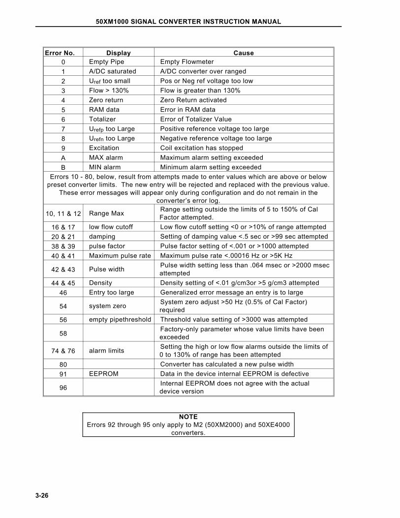
Error No. Display Cause0 Empty Pipe Empty Flowmeter1 A/DC saturated A/DC converter over ranged2 Uref too small Pos or Neg ref voltage too low3 Flow > 130% Flow is greater than 130%4 Zero return Zero Return activated5 RAM data Error in RAM data6 Totalizer Error of Totalizer Value7 Urefp too Large Positive reference voltage too large8 Urefn too Large Negative reference voltage too large9 Excitation Coil excitation has stoppedA MAX alarm Maximum alarm setting exceededB MIN alarm Minimum alarm setting exceeded
Errors 10 - 80, below, result from attempts made to enter values which are above or belowpreset converter limits. The new entry will be rejected and replaced with the previous value.
These error messages will appear only during configuration and do not remain in theconverter’s error log.
10, 11 & 12 Range Max Range setting outside the limits of 5 to 150% of Cal Factor attempted.
16 & 17 low flow cutoff Low flow cutoff setting <0 or >10% of range attempted20 & 21 damping Setting of damping value <.5 sec or >99 sec attempted38 & 39 pulse factor Pulse factor setting of <.001 or >1000 attempted40 & 41 Maximum pulse rate Maximum pulse rate <.00016 Hz or >5K Hz
42 & 43 Pulse width Pulse width setting less than .064 msec or >2000 msec attempted
44 & 45 Density Density setting of <.01 g/cm3or >5 g/cm3 attempted46 Entry too large Generalized error message an entry is to large
54 system zero System zero adjust >50 Hz (0.5% of Cal Factor) required
56 empty pipethreshold Threshold value setting of >3000 was attempted
58 Factory-only parameter whose value limits have been exceeded
74 & 76 alarm limits Setting the high or low flow alarms outside the limits of 0 to 130% of range has been attempted
80 Converter has calculated a new pulse width91 EEPROM Data in the device internal EEPROM is defective
96 Internal EEPROM does not agree with the actual device version
NOTEErrors 92 through 95 only apply to M2 (50XM2000) and 50XE4000
converters.
50XM1000 SIGNAL CONVERTER INSTRUCTION MANUAL
3-26
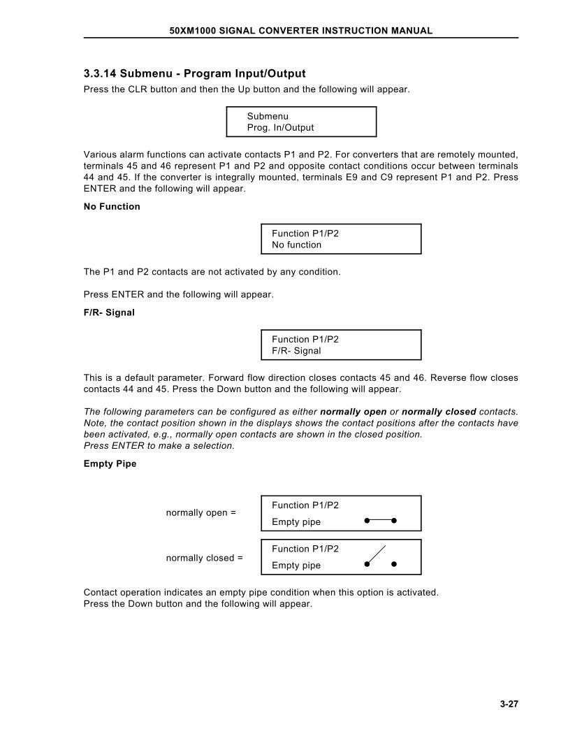
3.3.14 Submenu - Program Input/OutputPress the CLR button and then the Up button and the following will appear.
SubmenuProg. In/Output
Various alarm functions can activate contacts P1 and P2. For converters that are remotely mounted,terminals 45 and 46 represent P1 and P2 and opposite contact conditions occur between terminals44 and 45. If the converter is integrally mounted, terminals E9 and C9 represent P1 and P2. PressENTER and the following will appear.
No Function
Function P1/P2No function
The P1 and P2 contacts are not activated by any condition.
Press ENTER and the following will appear.
F/R- Signal
Function P1/P2F/R- Signal
This is a default parameter. Forward flow direction closes contacts 45 and 46. Reverse flow closescontacts 44 and 45. Press the Down button and the following will appear.
The following parameters can be configured as either normally open or normally closed contacts.Note, the contact position shown in the displays shows the contact positions after the contacts havebeen activated, e.g., normally open contacts are shown in the closed position. Press ENTER to make a selection.
Empty Pipe
Function P1/P2
Empty pipe • •
Function P1/P2
Empty pipe • •
Contact operation indicates an empty pipe condition when this option is activated. Press the Down button and the following will appear.
normally open =
normally closed =
50XM1000 SIGNAL CONVERTER INSTRUCTION MANUAL
3-27
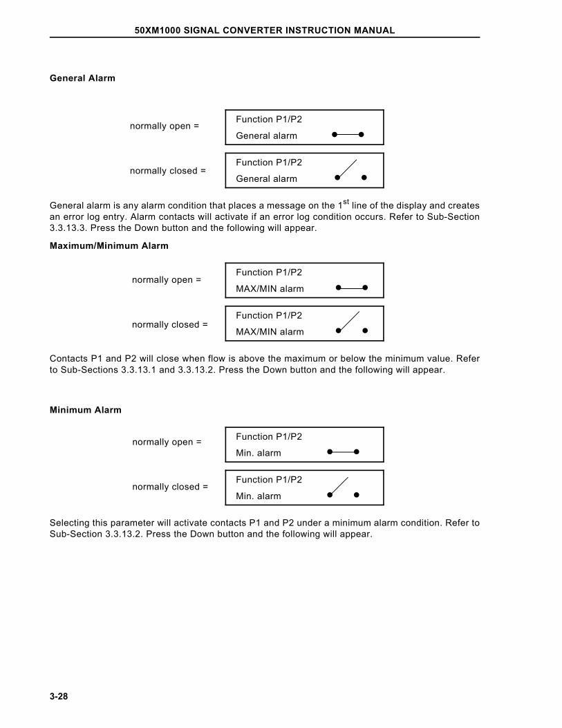
General Alarm
Function P1/P2
General alarm • •
Function P1/P2
General alarm • •
General alarm is any alarm condition that places a message on the 1st line of the display and createsan error log entry. Alarm contacts will activate if an error log condition occurs. Refer to Sub-Section3.3.13.3. Press the Down button and the following will appear.
Maximum/Minimum Alarm
Function P1/P2
MAX/MIN alarm • •
Function P1/P2
MAX/MIN alarm • •
Contacts P1 and P2 will close when flow is above the maximum or below the minimum value. Referto Sub-Sections 3.3.13.1 and 3.3.13.2. Press the Down button and the following will appear.
Minimum Alarm
Function P1/P2
Min. alarm • •
Function P1/P2
Min. alarm • •
Selecting this parameter will activate contacts P1 and P2 under a minimum alarm condition. Refer toSub-Section 3.3.13.2. Press the Down button and the following will appear.
normally open =
normally closed =
normally open =
normally closed =
normally open =
normally closed =
50XM1000 SIGNAL CONVERTER INSTRUCTION MANUAL
3-28
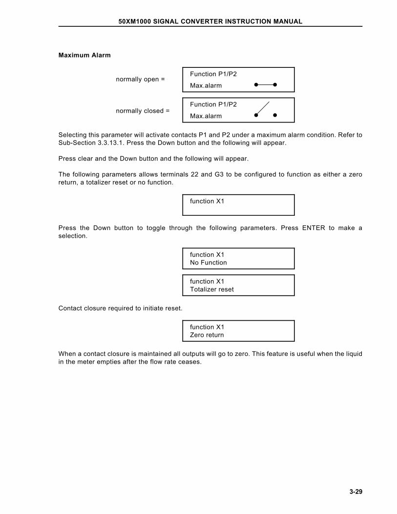
Maximum Alarm
Function P1/P2
Max.alarm • •
Function P1/P2
Max.alarm • •
Selecting this parameter will activate contacts P1 and P2 under a maximum alarm condition. Refer toSub-Section 3.3.13.1. Press the Down button and the following will appear.
Press clear and the Down button and the following will appear.
The following parameters allows terminals 22 and G3 to be configured to function as either a zeroreturn, a totalizer reset or no function.
function X1
Press the Down button to toggle through the following parameters. Press ENTER to make aselection.
function X1No Function
function X1Totalizer reset
Contact closure required to initiate reset.
function X1Zero return
When a contact closure is maintained all outputs will go to zero. This feature is useful when the liquidin the meter empties after the flow rate ceases.
normally open =
normally closed =
50XM1000 SIGNAL CONVERTER INSTRUCTION MANUAL
3-29
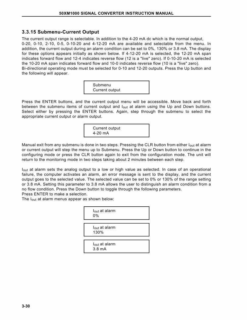
3.3.15 Submenu-Current OutputThe current output range is selectable. In addition to the 4-20 mA dc which is the normal output, 0-20, 0-10, 2-10, 0-5, 0-10-20 and 4-12-20 mA are available and selectable from the menu. Inaddition, the current output during an alarm condition can be set to 0%, 130% or 3.8 mA. The displayfor these options appears initially as shown below. If 4-12-20 mA is selected, the 12-20 mA spanindicates forward flow and 12-4 indicates reverse flow (12 is a "live" zero). If 0-10-20 mA is selectedthe 10-20 mA span indicates forward flow and 10-0 indicates reverse flow (10 is a "live" zero). Bi-directional operating mode must be selected for 0-10 and 12-20 outputs. Press the Up button andthe following will appear.
SubmenuCurrent output
Press the ENTER buttons, and the current output menu will be accessible. Move back and forthbetween the submenu items of current output and Iout at alarm using the Up and Down buttons.Select either by pressing the ENTER buttons. Again, step through the submenu to select theappropriate current output or alarm output.
Current output4-20 mA
Manual exit from any submenu is done in two steps. Pressing the CLR button from either Iout at alarmor current output will step the menu up to Submenu. Press the Up or Down button to continue in theconfiguring mode or press the CLR button again to exit from the configuration mode. The unit willreturn to the monitoring mode in two steps taking about 2 minutes between each step.
Iout at alarm sets the analog output to a low or high value as selected. In case of an operationalfailure, the computer activates an alarm, an error message is sent to the display, and the currentoutput goes to the selected value. The selected value can be set to 0% or 130% of the range settingor 3.8 mA. Setting this parameter to 3.8 mA allows the user to distinguish an alarm condition from ano flow condition. Press the Down button to toggle through the following parameters. Press ENTER to make a selection.The Iout at alarm menus appear as shown below:
Iout at alarm0%
Iout at alarm130%
Iout at alarm3.8 mA
50XM1000 SIGNAL CONVERTER INSTRUCTION MANUAL
3-30
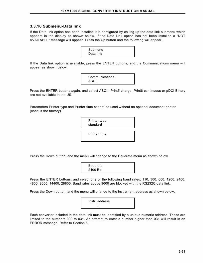
3.3.16 Submenu-Data linkIf the Data link option has been installed it is configured by calling up the data link submenu whichappears in the display as shown below. If the Data Link option has not been installed a "NOTAVAILABLE" message will appear. Press the Up button and the following will appear.
SubmenuData link
If the Data link option is available, press the ENTER buttons, and the Communications menu willappear as shown below.
CommunicationsASCII
Press the ENTER buttons again, and select ASCII. Print5 charge, Print6 continuous or µDCI Binaryare not available in the US.
Parameters Printer type and Printer time cannot be used without an optional document printer (consult the factory).
Printer typestandard
Printer time
Press the Down button, and the menu will change to the Baudrate menu as shown below.
Baudrate2400 Bd
Press the ENTER buttons, and select one of the following baud rates: 110, 300, 600, 1200, 2400,4800, 9600, 14400, 28800. Baud rates above 9600 are blocked with the RS232C data link.
Press the Down button, and the menu will change to the instrument address as shown below.
Instr. address 0
Each converter included in the data link must be identified by a unique numeric address. These arelimited to the numbers 000 to 031. An attempt to enter a number higher than 031 will result in anERROR message. Refer to Section 6.
50XM1000 SIGNAL CONVERTER INSTRUCTION MANUAL
3-31
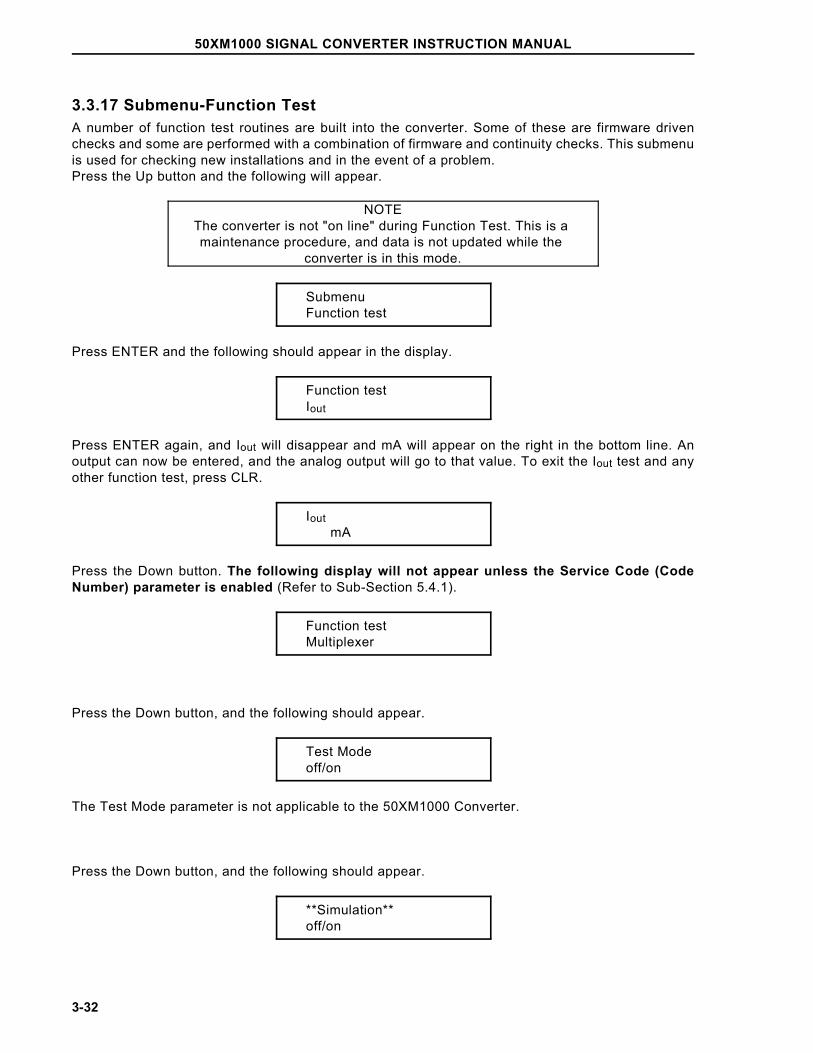
3.3.17 Submenu-Function TestA number of function test routines are built into the converter. Some of these are firmware drivenchecks and some are performed with a combination of firmware and continuity checks. This submenuis used for checking new installations and in the event of a problem.Press the Up button and the following will appear.
NOTEThe converter is not "on line" during Function Test. This is a maintenance procedure, and data is not updated while the
converter is in this mode.
SubmenuFunction test
Press ENTER and the following should appear in the display.
Function testIout
Press ENTER again, and Iout will disappear and mA will appear on the right in the bottom line. Anoutput can now be entered, and the analog output will go to that value. To exit the Iout test and anyother function test, press CLR.
Iout mA
Press the Down button. The following display will not appear unless the Service Code (CodeNumber) parameter is enabled (Refer to Sub-Section 5.4.1).
Function testMultiplexer
Press the Down button, and the following should appear.
Test Modeoff/on
The Test Mode parameter is not applicable to the 50XM1000 Converter.
Press the Down button, and the following should appear.
**Simulation**off/on
50XM1000 SIGNAL CONVERTER INSTRUCTION MANUAL
3-32
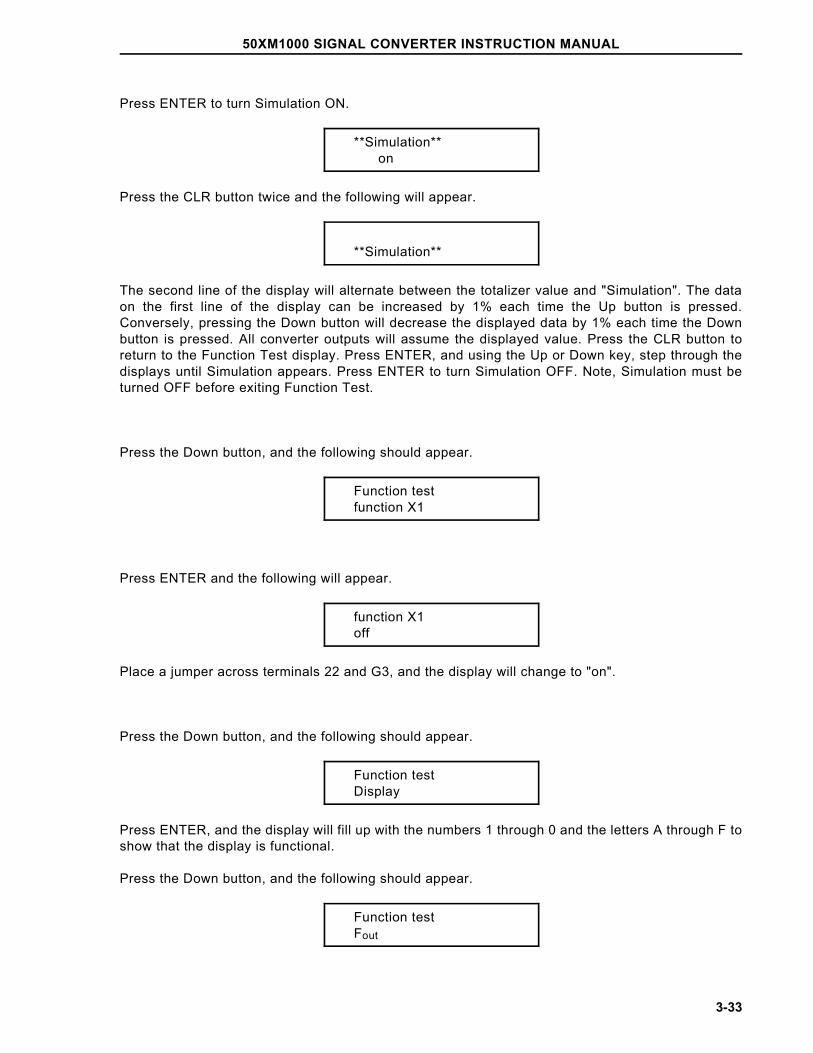
Press ENTER to turn Simulation ON.
**Simulation** on
Press the CLR button twice and the following will appear.
**Simulation**
The second line of the display will alternate between the totalizer value and "Simulation". The dataon the first line of the display can be increased by 1% each time the Up button is pressed.Conversely, pressing the Down button will decrease the displayed data by 1% each time the Downbutton is pressed. All converter outputs will assume the displayed value. Press the CLR button toreturn to the Function Test display. Press ENTER, and using the Up or Down key, step through thedisplays until Simulation appears. Press ENTER to turn Simulation OFF. Note, Simulation must beturned OFF before exiting Function Test.
Press the Down button, and the following should appear.
Function testfunction X1
Press ENTER and the following will appear.
function X1off
Place a jumper across terminals 22 and G3, and the display will change to "on".
Press the Down button, and the following should appear.
Function testDisplay
Press ENTER, and the display will fill up with the numbers 1 through 0 and the letters A through F toshow that the display is functional.
Press the Down button, and the following should appear.
Function testFout
50XM1000 SIGNAL CONVERTER INSTRUCTION MANUAL
3-33
Note that 10,000 Hz represents the full scale range setting of the instrument.
A function test of the frequency output will test the 0 to 10KHz unscaled output, and the optionalscaled pulse output if it is present in the converter.
Negative frequencies can be entered for testing reverse flow totalizers.
Press the Down button, and the following should appear.
Function testData link
The Data Link check requires that jumpers be installed in the wiring so that the converter can transmitand receive its own signal. For the RS 232 link, place the jumper between terminals TD and RD. Forthe RS 485 link, place a jumper between terminals T- and R- and another between T+ and R+. Theseterminals are located in the converter customer connection box.
Press ENTER. The computer will output 1000 characters of ASCII code 31 Hex ("1") and check thereceived characters. In the display, the output data count appears on the left, and the error datacount appears on the right. After 1000 characters are sent, the computer ends the check on thereceived data and continues to transmit the value 31 Hex until the CLR button is pressed.
Press the Down button, and the following should appear.
Function testSwitch S401
The Switch S401 test is for factory use only
Function testfunction P1/P2
This parameter exercises contacts 44, 45 and 46, also identified as P1/P2.
Press the Down button, and the following should appear.
Function testAlarm contact
This test checks the alarm contacts 39 and 40 (V5 and V6).
50XM1000 SIGNAL CONVERTER INSTRUCTION MANUAL
3-34
Press ENTER, and the display will show "Alarm contact" on the top line, and either Off or On on thebottom line. Press the Up button to switch from On to Off. Continuity should be present when themenu reads On.
Function testExternal EEPROM
The external EEPROM test is not applicable to 50XM1000 Converters.
Press the Down button and the EEPROM test should appear as shown below.
Function testEEPROM
Press the Down button, and the following should appear.
Function testEPROM (Program)
Press ENTER and an EPROM OK or an ERROR message will appear in the display.
Press the Down button and the NVRAM check should appear as shown below.
Function testNVRAM
Press ENTER and an NVRAM OK or an ERROR message will appear in the display.
Press the Down button and the RAM check should appear as shown below.
Function testRAM (ASIC)
50XM1000 SIGNAL CONVERTER INSTRUCTION MANUAL
3-35
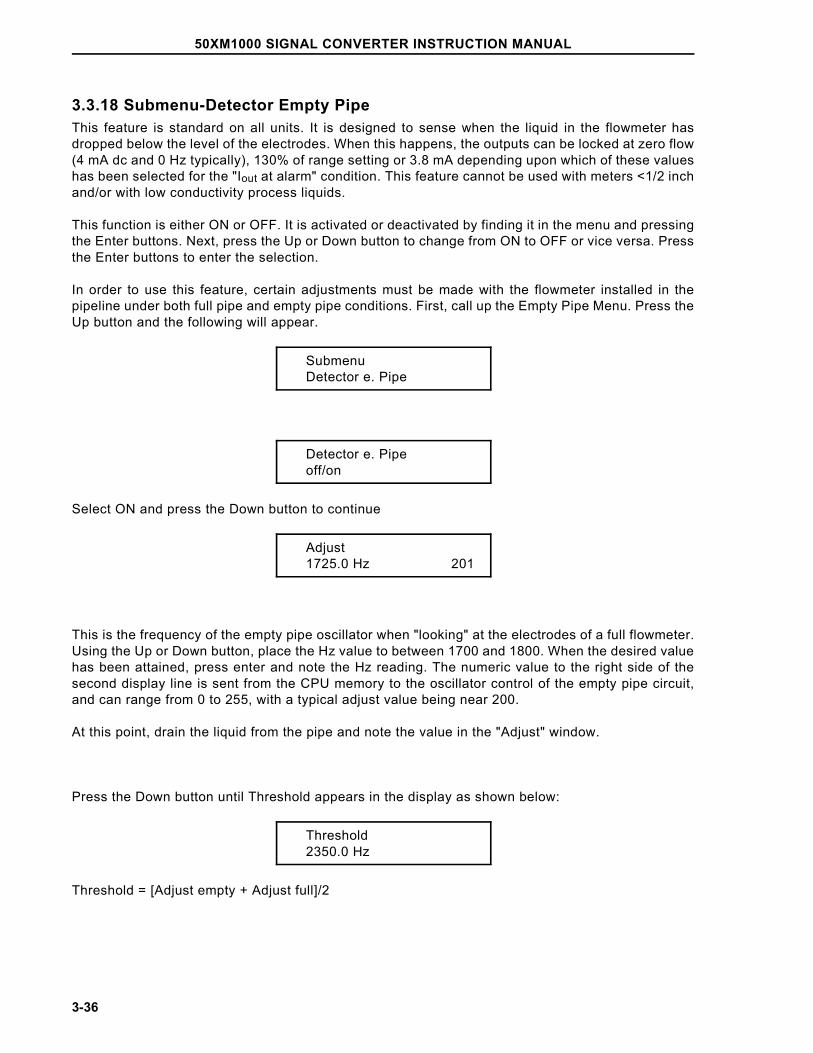
3.3.18 Submenu-Detector Empty PipeThis feature is standard on all units. It is designed to sense when the liquid in the flowmeter hasdropped below the level of the electrodes. When this happens, the outputs can be locked at zero flow(4 mA dc and 0 Hz typically), 130% of range setting or 3.8 mA depending upon which of these valueshas been selected for the "Iout at alarm" condition. This feature cannot be used with meters <1/2 inchand/or with low conductivity process liquids.
This function is either ON or OFF. It is activated or deactivated by finding it in the menu and pressingthe Enter buttons. Next, press the Up or Down button to change from ON to OFF or vice versa. Pressthe Enter buttons to enter the selection.
In order to use this feature, certain adjustments must be made with the flowmeter installed in thepipeline under both full pipe and empty pipe conditions. First, call up the Empty Pipe Menu. Press theUp button and the following will appear.
SubmenuDetector e. Pipe
Detector e. Pipeoff/on
Select ON and press the Down button to continue
Adjust1725.0 Hz 201
This is the frequency of the empty pipe oscillator when "looking" at the electrodes of a full flowmeter.Using the Up or Down button, place the Hz value to between 1700 and 1800. When the desired valuehas been attained, press enter and note the Hz reading. The numeric value to the right side of thesecond display line is sent from the CPU memory to the oscillator control of the empty pipe circuit,and can range from 0 to 255, with a typical adjust value being near 200.
At this point, drain the liquid from the pipe and note the value in the "Adjust" window.
Press the Down button until Threshold appears in the display as shown below:
Threshold2350.0 Hz
Threshold = [Adjust empty + Adjust full]/2
50XM1000 SIGNAL CONVERTER INSTRUCTION MANUAL
3-36
Example:
Full pipe adjust value is 1725 Hz and the empty pipe adjust value is 2975 Hz. The Threshold shouldbe set as follows:
Threshold = [2975 + 1725]/2 = 2350 Hz
Press ENTER and change the numerical value that appears on the second line of the display to thevalue calculated above.
Press the Down button, and the following should appear.
Iout at empty pi(pe) %
This parameter can be set at 0%, 130% or 3.8 mA, as desired.
Press the Down button, and the following should appear.
alarm empty pipeoff/on
This parameter determines whether an empty pipe will cause an alarm at contacts V5 and V6.
3.3.19 Submenu-TotalizerThe totalizer is reset and overflows cleared using this submenu. Totalizer "Standard" separates thetotalizer into forward and reverse flow. Totalizer "differ. total" (differential totalizer) displays thedifference between forward and reverse flow.
Press the Up button and the following will appear.
Submenutotalizer
Press ENTER and the following will appear.
Totalizerreset
50XM1000 SIGNAL CONVERTER INSTRUCTION MANUAL
3-37
The Forward and Reverse totalizers can be reset to zero individually. Toggle through the menu untilthe Totalizer> F reset message appears in the display. Forward or reverse flow will be indicated by"> F" and "< R". Press the ENTER buttons, and the appropriate counter will be reset to zero. Pressthe Down button and the following will appear.
Mains interruptreset
The converter may be configured for Custody Transfer (Billing) applications using Switch S401(location of switch is shown in Figure 1-4). In this mode, a power interruption will create a flashingasterisk to the right of the flow rate indicator. Pressing ENTER under this submenu clears thatasterisk.
Press the Down button and the following will appear.
Overflow →F
Overflow ←R
When the totalizer reaches its maximum count (9,999,999,) it "rolls over" and starts to count again atzero. When this occurs, the direction indicator (> F or < R) at the left of the register and the units (i.e.,gal) at the right of the register will blink, and an overflow register will record the overflow. Thecumulative total can be determined by multiplying the number in the overflow register times10,000,000 and adding the value in the totals register. The overflow message is removed by togglingthrough the menu using the Up or Down button. At this time, pressing the ENTER buttons will resetthe overflow register, and the blinking will stop.
Press the Down button and the following will appear.
Totalizer functstandard/differ. total
Press the ENTER buttons and the cursor will appear to the right of "standard". Press the Up or Downbutton and the indication will toggle between "standard" and "differ. total".
"Differ. total" subtracts reverse flow from forward flow. Indication shows net direction and value.
3.3.20 Submenu-DisplayThe Submenu Display parameters can be configured by selecting the appropriate parameters listedbelow and entering the desired information. Some parameters are only available (as indicted) whenthe Code Number (Service Code) is activated (refer to 5.4.1). The display may be configured so thatany available information may be placed on either first or second line of the display.
In addition, a multiplex feature is available which can alternate any of two sets of parameters oneither line of the display. This feature can be activated by turning ON the line(s) of the display desiredfor multiplexing and then selecting the parameter to be shown. The display will alternate between thedisplay value and the multiplex value approximately every 7 seconds.
50XM1000 SIGNAL CONVERTER INSTRUCTION MANUAL
3-38
Press the Up button and the following will appear.
SubmenuDisplay
Press ENTER and the following will appear
1st line
2nd line
Press the Down button and the following parameters will appear on the display.
Q [%] - flow rate as a percentage of range setting
Q [Bargraph] - left to right graphic of flow rate as a percentage of range, with nu-meric percentage to the right of the bar graph
TAG number - not available for the 50XM1000
Totalizer - ←R totalized flow for reverse direction only
Totalizer - →F totalized flow for forward direction only
Totalizer - totalized flow for the direction currently indicated on the flow rate display
Q [mA] - flow rate expressed as the number of mA present at the + and – analogoutput terminals
Q [unit] - flow rate in actual selected units
The second display line can also be chosen as blank
The Code Number (Service Code), see 5.4.1, must be enabled to display the following parametersthat are included in the Display Submenu.
Detector e.p.
Reference p/n
Signal p/n
Refer to Sub Section 7.3.
50XM1000 SIGNAL CONVERTER INSTRUCTION MANUAL
3-39
3.3.21 Submenu-Operating ModePress the Up button and the following menu will appear.
Operating modestandard
Press ENTER and the Down button to display the following menu.
Operating mode* Fast
* Consult the factory for applications assistance before selectingthe Fast mode. This mode is used to specifically characterizeconverter response.
Flow IndicationThis feature makes it possible to reverse the forward and reverse flow signals. If the flowmeter isinstalled so that flow through the meter is in the direction opposite to that in which it is wired andcalibrated, the flow indication will be reversed. Forward flow will read as reverse flow and vice versa.This can be corrected by reversing the wires on terminals 1 and 2 of either the flowmeter or the signalconverter. This change can be made through the firmware by selecting the flow indication feature.
Press the Down button and the following will appear.
Flow indicationstandard/opposite
Press the ENTER buttons and the cursor will appear to the right of "standard". Press the Up or Downbutton and the indication will toggle between standard and opposite. Select opposite, press ENTER,and the flowrate and totalizer indications will display in the forward direction even though theflowmeter has been installed so that the actual flow enters from the reverse direction. The purpose ofthis parameter is to compensate for the incorrect installation of the meter. Note that the flow arrowon the meter points in the opposite direction of actual flow.
FlowdirectionThe converter offers bidirectional and forward only flow measurement. If the converter is in theforward mode, the parameters Range R, Pulse Factor R and Multiplex Display are not available.
Press ENTER and the Down button to display the following menu. Press ENTER to enter a selection.
Flowdirectionforward/reverse
50XM1000 SIGNAL CONVERTER INSTRUCTION MANUAL
3-40
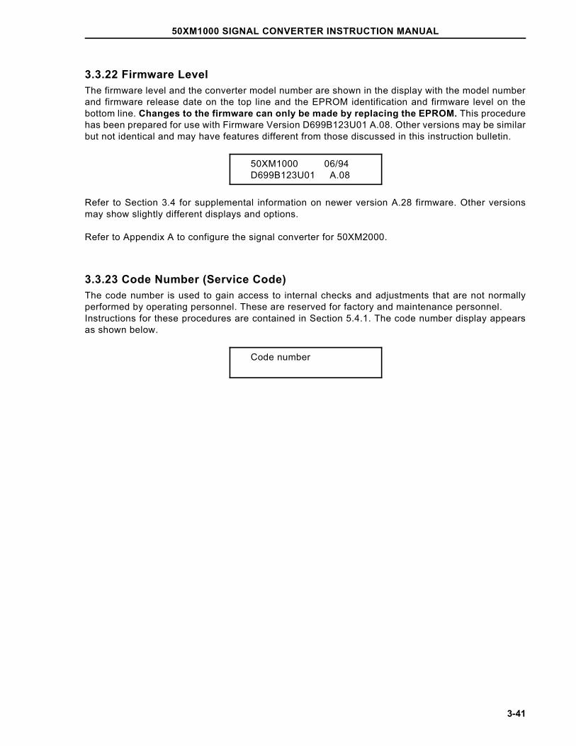
3.3.22 Firmware LevelThe firmware level and the converter model number are shown in the display with the model numberand firmware release date on the top line and the EPROM identification and firmware level on thebottom line. Changes to the firmware can only be made by replacing the EPROM. This procedurehas been prepared for use with Firmware Version D699B123U01 A.08. Other versions may be similarbut not identical and may have features different from those discussed in this instruction bulletin.
50XM1000 06/94D699B123U01 A.08
Refer to Section 3.4 for supplemental information on newer version A.28 firmware. Other versionsmay show slightly different displays and options.
Refer to Appendix A to configure the signal converter for 50XM2000.
3.3.23 Code Number (Service Code)The code number is used to gain access to internal checks and adjustments that are not normallyperformed by operating personnel. These are reserved for factory and maintenance personnel. Instructions for these procedures are contained in Section 5.4.1. The code number display appearsas shown below.
Code number
50XM1000 SIGNAL CONVERTER INSTRUCTION MANUAL
3-41
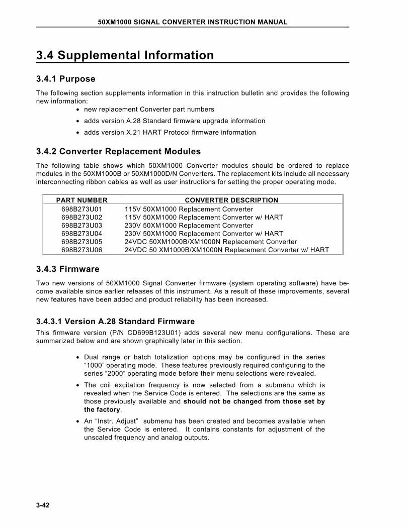
3.4 Supplemental Information
3.4.1 PurposeThe following section supplements information in this instruction bulletin and provides the followingnew information:
• new replacement Converter part numbers
• adds version A.28 Standard firmware upgrade information
• adds version X.21 HART Protocol firmware information
3.4.2 Converter Replacement ModulesThe following table shows which 50XM1000 Converter modules should be ordered to replacemodules in the 50XM1000B or 50XM1000D/N Converters. The replacement kits include all necessaryinterconnecting ribbon cables as well as user instructions for setting the proper operating mode.
PART NUMBER CONVERTER DESCRIPTION698B273U01698B273U02698B273U03698B273U04698B273U05698B273U06
115V 50XM1000 Replacement Converter115V 50XM1000 Replacement Converter w/ HART230V 50XM1000 Replacement Converter230V 50XM1000 Replacement Converter w/ HART24VDC 50XM1000B/XM1000N Replacement Converter24VDC 50 XM1000B/XM1000N Replacement Converter w/ HART
3.4.3 FirmwareTwo new versions of 50XM1000 Signal Converter firmware (system operating software) have be-come available since earlier releases of this instrument. As a result of these improvements, severalnew features have been added and product reliability has been increased.
3.4.3.1 Version A.28 Standard FirmwareThis firmware version (P/N CD699B123U01) adds several new menu configurations. These aresummarized below and are shown graphically later in this section.
• Dual range or batch totalization options may be configured in the series“1000” operating mode. These features previously required configuring to theseries “2000” operating mode before their menu selections were revealed.
• The coil excitation frequency is now selected from a submenu which isrevealed when the Service Code is entered. The selections are the same asthose previously available and should not be changed from those set bythe factory.
• An “Instr. Adjust” submenu has been created and becomes available whenthe Service Code is entered. It contains constants for adjustment of theunscaled frequency and analog outputs.
50XM1000 SIGNAL CONVERTER INSTRUCTION MANUAL
3-42
• An “Options” submenu has been created and appears after the Service Codeis entered. It defines the startup mode of the instrument (Language, etc.) andthe type of circuit card plugged into the option socket (data link, pulse).
• "System Zero" has been limited to a maximum + 0.5% of meter capacity (+50Hz). This may present some problems when using the new converters witholder primaries, many of which require more than this limited amount of zerooffset.
If using version A.28 firmware in conjunction with an older Primary causes an error message to bedisplayed when attempting to perform a system zero, contact Tech Support or Product Management.This may indicate that A.28 firmware is not compatible with the older Primary.
The corresponding menus for the items described above for the A.28 firmware are shown on the nextpage.
50XM1000 SIGNAL CONVERTER INSTRUCTION MANUAL
3-43
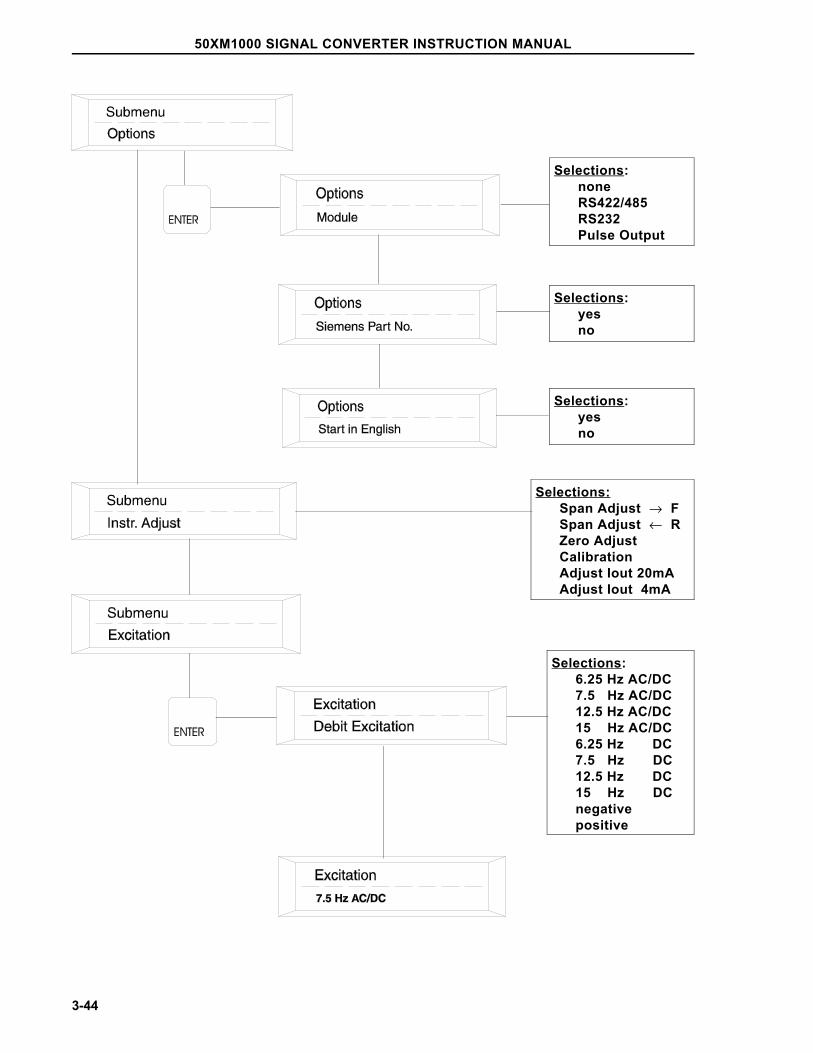
Selections:noneRS422/485RS232Pulse Output
Selections:yesno
Selections:Span Adjust → FSpan Adjust ← RZero AdjustCalibrationAdjust Iout 20mAAdjust Iout 4mA
Selections:6.25 Hz AC/DC7.5 Hz AC/DC12.5 Hz AC/DC15 Hz AC/DC6.25 Hz DC7.5 Hz DC12.5 Hz DC15 Hz DCnegativepositive
Selections:yesno
50XM1000 SIGNAL CONVERTER INSTRUCTION MANUAL
3-44
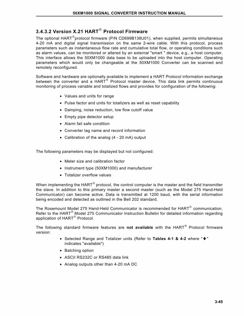
3.4.3.2 Version X.21 HART Protocol FirmwareThe optional HARTprotocol firmware (P/N CD699B138U01), when supplied, permits simultaneous4-20 mA and digital signal transmission on the same 2-wire cable. With this protocol, processparameters such as instantaneous flow rate and cumulative total flow, or operating conditions suchas alarm values, can be monitored or altered by an external "smart " device, e.g., a host computer.This interface allows the 50XM1000 data base to be uploaded into the host computer. Operatingparameters which would only be changeable at the 50XM1000 Converter can be scanned andremotely reconfigured.
Software and hardware are optionally available to implement a HART Protocol information exchangebetween the converter and a HART Protocol master device. This data link permits continuousmonitoring of process variable and totalized flows and provides for configuration of the following:
• Values and units for range
• Pulse factor and units for totalizers as well as reset capability
• Damping, noise reduction, low flow cutoff value
• Empty pipe detector setup
• Alarm fail safe condition
• Converter tag name and record information
• Calibration of the analog (4 - 20 mA) output
The following parameters may be displayed but not configured:
• Meter size and calibration factor
• Instrument type (50XM1000) and manufacturer
• Totalizer overflow values
When implementing the HART protocol, the control computer is the master and the field transmitterthe slave. In addition to this primary master a second master (such as the Model 275 Hand-HeldCommunicator) can become active. Data is transmitted at 1200 baud, with the serial informationbeing encoded and detected as outlined in the Bell 202 standard.
The Rosemount Model 275 Hand-Held Communicator is recommended for HART communication.Refer to the HART Model 275 Communicator Instruction Bulletin for detailed information regardingapplication of HART Protocol.
The following standard firmware features are not available with the HART Protocol firmwareversion:
• Selected Range and Totalizer units (Refer to Tables 4-1 & 4-2 where "♦"indicates "available")
• Batching option
• ASCII RS232C or RS485 data link
• Analog outputs other than 4-20 mA DC
50XM1000 SIGNAL CONVERTER INSTRUCTION MANUAL
3-45
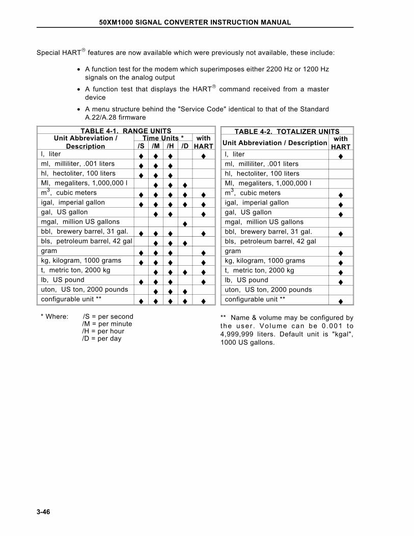
Special HART features are now available which were previously not available, these include:
• A function test for the modem which superimposes either 2200 Hz or 1200 Hzsignals on the analog output
• A function test that displays the HART command received from a masterdevice
• A menu structure behind the "Service Code" identical to that of the StandardA.22/A.28 firmware
TABLE 4-1. RANGE UNITSUnit Abbreviation /
DescriptionTime Units * with
HART/S /M /H /Dl, liter ♦ ♦ ♦ ♦ml, milliliter, .001 liters ♦ ♦ ♦hl, hectoliter, 100 liters ♦ ♦ ♦Ml, megaliters, 1,000,000 l ♦ ♦ ♦m3, cubic meters ♦ ♦ ♦ ♦ ♦igal, imperial gallon ♦ ♦ ♦ ♦ ♦gal, US gallon ♦ ♦ ♦mgal, million US gallons ♦bbl, brewery barrel, 31 gal. ♦ ♦ ♦ ♦bls, petroleum barrel, 42 gal ♦ ♦ ♦gram ♦ ♦ ♦ ♦kg, kilogram, 1000 grams ♦ ♦ ♦ ♦t, metric ton, 2000 kg ♦ ♦ ♦ ♦lb, US pound ♦ ♦ ♦ ♦uton, US ton, 2000 pounds ♦ ♦ ♦configurable unit ** ♦ ♦ ♦ ♦ ♦
* Where: /S = per second /M = per minute /H = per hour /D = per day
TABLE 4-2. TOTALIZER UNITSUnit Abbreviation / Description with
HARTl, liter ♦ml, milliliter, .001 litershl, hectoliter, 100 litersMl, megaliters, 1,000,000 lm3, cubic meters ♦igal, imperial gallon ♦gal, US gallon ♦mgal, million US gallonsbbl, brewery barrel, 31 gal. ♦bls, petroleum barrel, 42 galgram ♦kg, kilogram, 1000 grams ♦t, metric ton, 2000 kg ♦lb, US pound ♦uton, US ton, 2000 poundsconfigurable unit ** ♦
** Name & volume may be configured bythe user . Vo lume can be 0 .001 to4,999,999 liters. Default unit is "kgal",1000 US gallons.
50XM1000 SIGNAL CONVERTER INSTRUCTION MANUAL
3-46
4.0 FUNCTIONAL DESCRIPTION
4.1 Basic FunctionsThe signal converter is of the pulsed dc type, i.e., it supplies a pulsed constant current dc signal tothe magnet coils of the flowmeter to establish the magnetic field. Also it receives the electrode flowsignal from the flowmeter, and converts it into analog and digital output signals. Zero is factory set,and no field zero adjustments are required.
Two field selectable coil operating frequencies are incorporated in this design. They are 7.5 Hz and15 Hz for 60 Hz power and 6.25 and 12.5 Hz for 50 Hz power. The standard coil drive frequency is7.5 Hz. The 15 Hz, when used with the digital filter feature, is only recommended for applications inwhich the process generates noise signals that interfere with the flow signal.
4.2 Design Features
4.2.1 Micro-Processor ControlledThe converter is micro-processor controlled with nonvolatile memory. All operating parameters areconfigurable via three pushbuttons on the converter or via an optional data link. During configuration,the converter remains on line, and data is updated continually. The data base is updated at the timethe ENTER buttons are pressed to enter a parameter change.
4.2.2 DisplayThe liquid crystal display (LCD) is back lit and contains two lines of 16 alphameric (5 X 7 dot matrix)characters. The display is used to show flow rate on the top line in either percent of flow or in directengineering units and totalization in direct engineering units on the bottom line (see Figure 3-4). Inaddition, the display is used to show configuring data or error messages in English language (or theselected language). Both the rate indicator and the seven digit totalizer are included in everyconverter as standard.
4.2.3 RangeabilityAny flow rate from 0 to 100% can be measured provided the full scale value is between 49 ft/s (15 m/s) and 0.66 ft/s (0.2 m/s).
4.2.4 Bi-Directional FlowThe converter can be either unidirectional or bidirectional. Selection of the directional mode is madethrough firmware. The standard mode is unidirectional. This can easily be changed at the factory orin the field. Instructions for this firmware change are contained in Section 3.3.21. In the bidirectionalmode, the converter will automatically display rate and totalization in forward and reverse directions.A pulse output option for each direction is available for retransmission to an external totalizer. A flowdirection contact is included in the converter to indicate flow direction for the one analog output.
50XM1000 SIGNAL CONVERTER INSTRUCTION MANUAL
4-1
4.2.5 Flow DirectionThe flow direction is indicated at the left side of the display as "F" for forward flow and "R" for reverseflow. Totalization is also shown in this manner. The totalizer can be switched manually from forwardto reverse or vice versa by pressing the Up or Down button located below the display. The totalizercan also be switched automatically every 7 seconds by selecting MULTIPLEX DISPLAY from theconfiguring menu.
A separate external totalizer for each flow direction can be driven by the 24 V dc scaled pulse if thescaled pulse option has been selected.
There is one analog output available. Flow in the reverse direction is indicated by the same analogsignal as the forward. To make the distinction between forward and reverse flow, contact closures areprovided in the converter. In a two pen recorder, for example, one pen could be used to record flowwhile the second pen could rest at zero with the contact open and could be elevated to some positivevalue when the contact closes. Therefore, the position of the second pen would indicate the directionof flow. If the analog signal goes to a computer or other intelligent instrument the contact closurecondition is easily recognized as an indication of flow direction. Also (alternatively) the zero centeranalog outputs may be selected (see 3.3.15).
4.2.6 Output Signals4.2.6.1 Analog OutputA 4-20 mA dc output signal into 0-750 ohms is standard and is always available regardless of whichoutput options are selected.
4.2.6.2 Incremental PulseThis is a 5 volt, 0-10 kHz unscaled frequency which is normally used during calibration. It can beadapted for use as an output in special applications. This output is also provided regardless of outputoptions.
4.2.6.3 Optional OutputsEither a scaled pulse output or a data link can be selected.
4.2.6.4 Scaled PulseThis is a 24 V dc pulse that operates a load of 150 ohms or more. It can be used to drive anelectromechanical counter at 0-10 Hz with a 50 millisecond pulse width or a high speed electronicdevice at 0-4 kHz with a 50 microsecond pulse width. The pulse width can be adjusted as a part ofthe data base and does not require a hardware change.
4.2.7 Data LinkThe data link is the hardware and firmware by which the data base may be examined. The data baseis a collection of elements in the converter memory which may be either altered or examined throughfirmware. In addition, the data base represents the information the instrument is working with in thecourse of its normal computations. A few of the parameters included in the data base are calibrationfactor, range setting, damping value and pulse width. The data link consists of two transmitting andtwo receiving wires which pass serial data at 110 bits per second up to 28,800 bits per second (110Baud to 28.8 kBaud). It does not carry the analog output signal from the con-verter. The analog signalis carried over its own wires directly to the receiving device (recorder, controller, indicator, computer,etc.) in the normal manner. There are two industry standard hardware arrangements for the data linkoption. They are RS232C and RS485.
50XM1000 SIGNAL CONVERTER INSTRUCTION MANUAL
4-2
The RS232C interface is probably the most common serial data link in use today. It permitscommunication between two devices normally within 50 feet (15 m) of each other at baud rates up toabout 9600. Devices are available to convert from RS232C to RS485 to allow connection of morethan one converter to a single computer and to transmit well beyond 50 feet.The RS485 interface isa high speed link used by intelligent instruments. It permits any transmitter to be shut off or ’tri-stated’when not in use. For instruments such as the company’s SUPERVISOR, it means that up to 32instruments may ’talk’ over one data link. This link can send data at 28.8 kBaud over lines up to 4000feet (1200 m). ASCII is the only key pad selectable communication mode available.
4.2.7.1 ASCIIIn the ASCII mode, a sequence of ASCII characters is sent back and forth.
4.2.8 PowerRefer to the converter data tag for power requirements.
50XM1000 SIGNAL CONVERTER INSTRUCTION MANUAL
4-3
5.0 CALIBRATION
5.1 General DiscussionNOTE
The signal converter should never require recalibration, unless a hardware failure has occurred. If the non-volatile memorydata proves defective, calibration data must be re-entered. In the
event of component failure, existing calibration data may no longerbe valid.
One notable feature of the converter is that it can be configured independent of any particularflowmeter, as long as the flowmeters are of the same size and use the constant meter factor/sizedesign concept. The design of the microprocessor-based converter permits configuration and calibra-tion of the converter prior to its installation.
Each converter is configured and precisely calibrated at the factory in accordance with customerspecified flow parameters.
Since the flow metering system is precalibrated, it is generally ready for on-line service as received.In the event that the specified system flow parameters or engineering units are to be changed, theconverter must be reconfigured to agree with the revised flow values.
Signal converter performance can be verified periodically using the procedure described in Section5.3. If problems are experienced which may be originating with the signal processor, use theperformance verification procedure first. Recalibration should be done only when it has been deter-mined that it is actually required. If calibration is necessary, it can be done using the proceduredescribed in Section 5.4.
Performance verification and calibration of the converter require the use of the Model 55XC2000 or55XC4000 Signal Simulator. The signal simulator is supplied with an interface adaptor which in-cludes test cables that mate with receptacles provided on the converter assembly.
Essential calibration data is recorded and listed on a data tag that is attached to the side of thetransformer in the signal converter assembly. The calibration data provided can be used to restorethe signal converter to a calibrated condition when data held in the non-volatile memory data hasbeen corrupted. RAM corruption can result from a lightning strike or severe electrical disturbancenear the installation site. In this event, all of the calibration data can be re-entered manually.However, if the signal converter has malfunctioned and a defective component must be replaced, thecalibration data is no longer valid; the unit must then be recalibrated as described in this section.
50XM1000 SIGNAL CONVERTER INSTRUCTION MANUAL
5-1
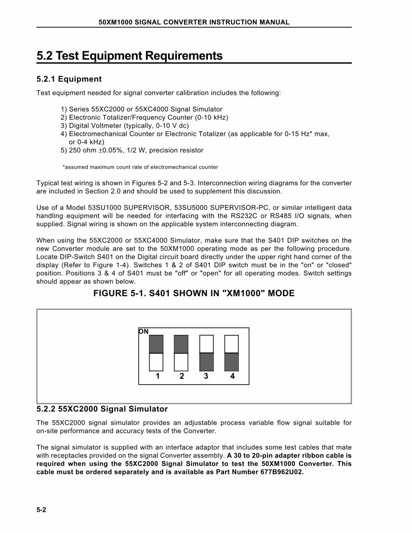
5.2 Test Equipment Requirements
5.2.1 EquipmentTest equipment needed for signal converter calibration includes the following:
1) Series 55XC2000 or 55XC4000 Signal Simulator2) Electronic Totalizer/Frequency Counter (0-10 kHz)3) Digital Voltmeter (typically, 0-10 V dc)4) Electromechanical Counter or Electronic Totalizer (as applicable for 0-15 Hz* max, or 0-4 kHz)5) 250 ohm ±0.05%, 1/2 W, precision resistor
*assumed maximum count rate of electromechanical counter
Typical test wiring is shown in Figures 5-2 and 5-3. Interconnection wiring diagrams for the converterare included in Section 2.0 and should be used to supplement this discussion.
Use of a Model 53SU1000 SUPERVISOR, 53SU5000 SUPERVISOR-PC, or similar intelligent datahandling equipment will be needed for interfacing with the RS232C or RS485 I/O signals, whensupplied. Signal wiring is shown on the applicable system interconnecting diagram.
When using the 55XC2000 or 55XC4000 Simulator, make sure that the S401 DIP switches on thenew Converter module are set to the 50XM1000 operating mode as per the following procedure.Locate DIP-Switch S401 on the Digital circuit board directly under the upper right hand corner of thedisplay (Refer to Figure 1-4). Switches 1 & 2 of S401 DIP switch must be in the "on" or "closed"position. Positions 3 & 4 of S401 must be "off" or "open" for all operating modes. Switch settingsshould appear as shown below.
FIGURE 5-1. S401 SHOWN IN "XM1000" MODE
5.2.2 55XC2000 Signal SimulatorThe 55XC2000 signal simulator provides an adjustable process variable flow signal suitable foron-site performance and accuracy tests of the Converter.
The signal simulator is supplied with an interface adaptor that includes some test cables that matewith receptacles provided on the signal Converter assembly. A 30 to 20-pin adapter ribbon cable isrequired when using the 55XC2000 Signal Simulator to test the 50XM1000 Converter. Thiscable must be ordered separately and is available as Part Number 677B962U02.
ON
1 2 3 4
50XM1000 SIGNAL CONVERTER INSTRUCTION MANUAL
5-2
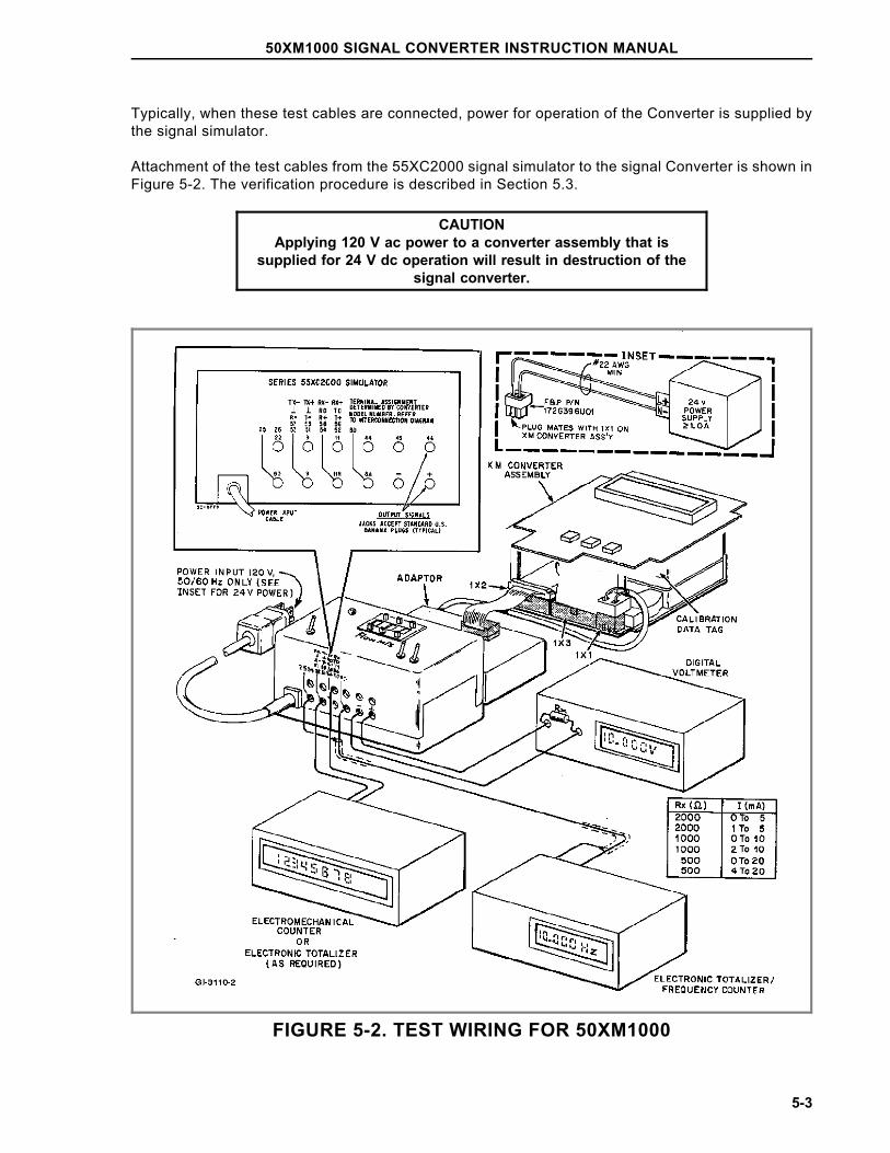
Typically, when these test cables are connected, power for operation of the Converter is supplied bythe signal simulator.
Attachment of the test cables from the 55XC2000 signal simulator to the signal Converter is shown inFigure 5-2. The verification procedure is described in Section 5.3.
CAUTIONApplying 120 V ac power to a converter assembly that is
supplied for 24 V dc operation will result in destruction of thesignal converter.
FIGURE 5-2. TEST WIRING FOR 50XM1000
50XM1000 SIGNAL CONVERTER INSTRUCTION MANUAL
5-3
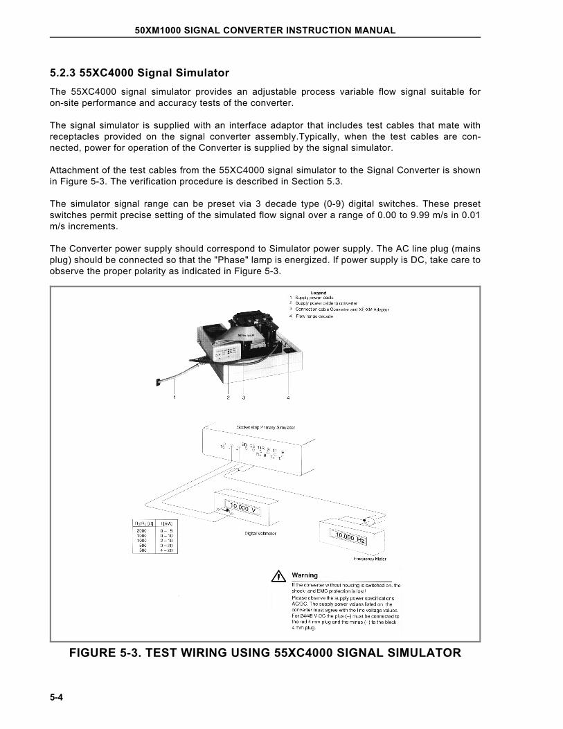
5.2.3 55XC4000 Signal SimulatorThe 55XC4000 signal simulator provides an adjustable process variable flow signal suitable foron-site performance and accuracy tests of the converter.
The signal simulator is supplied with an interface adaptor that includes test cables that mate withreceptacles provided on the signal converter assembly.Typically, when the test cables are con-nected, power for operation of the Converter is supplied by the signal simulator.
Attachment of the test cables from the 55XC4000 signal simulator to the Signal Converter is shownin Figure 5-3. The verification procedure is described in Section 5.3.
The simulator signal range can be preset via 3 decade type (0-9) digital switches. These presetswitches permit precise setting of the simulated flow signal over a range of 0.00 to 9.99 m/s in 0.01m/s increments.
The Converter power supply should correspond to Simulator power supply. The AC line plug (mainsplug) should be connected so that the "Phase" lamp is energized. If power supply is DC, take care toobserve the proper polarity as indicated in Figure 5-3.
FIGURE 5-3. TEST WIRING USING 55XC4000 SIGNAL SIMULATOR
50XM1000 SIGNAL CONVERTER INSTRUCTION MANUAL
5-4
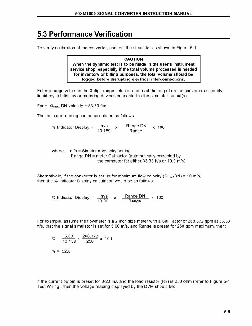
5.3 Performance VerificationTo verify calibration of the converter, connect the simulator as shown in Figure 5-1.
CAUTIONWhen the dynamic test is to be made in the user’s instrument
service shop, especially if the total volume processed is neededfor inventory or billing purposes, the total volume should be
logged before disrupting electrical interconnections.
Enter a range value on the 3-digit range selector and read the output on the converter assembly liquid crystal display or metering devices connected to the simulator output(s).
For = Qmax DN velocity = 33.33 ft/s
The indicator reading can be calculated as follows:
% Indicator Display = m/s x Range DN x 100 10.159 Range
where, m/s = Simulator velocity setting Range DN = meter Cal factor (automatically corrected by the computer for either 33.33 ft/s or 10.0 m/s)
Alternatively, if the converter is set up for maximum flow velocity (QmaxDN) = 10 m/s, then the % Indicator Display calculation would be as follows:
% Indicator Display = m/s x Range DN x 100 10.00 Range
For example, assume the flowmeter is a 2 inch size meter with a Cal Factor of 268.372 gpm at 33.33ft/s, that the signal simulator is set for 5.00 m/s, and Range is preset for 250 gpm maximum, then:
% = 5.0010.159 x 268.372
250 x 100
% = 52.8
If the current output is preset for 0-20 mA and the load resistor (Rx) is 250 ohm (refer to Figure 5-1Test Wiring), then the voltage reading displayed by the DVM should be:
50XM1000 SIGNAL CONVERTER INSTRUCTION MANUAL
5-5
E = (Imax x indicator %100 ) (Rx)
E = ( 0.020 x 52.8100.0 ) (250)
E = 2.64 V dc
The flow velocity in ft/s at the operating flow rate can be calculated as shown below.
ft/s = OPER(gpm) x 33.33 CALFACTOR(gpm)
Using values given in the above example,
ft/s = 250 x 33.33 = 31.0 268.372
To convert velocity in ft/s to m/s,
m/s = ft⁄s
3.2808
typically,
m/s = 31.03.2808 = 9.45
When satisfactory performance has been demonstrated, select the desired current output span (4-20, 0-20, 4-12-20, 0-10-20, 0-5, 2-10 or 0-10 mA) before returning the converter to service.Standard output is 4-20 mA.
50XM1000 SIGNAL CONVERTER INSTRUCTION MANUAL
5-6
5.4 Calibration ProcedureNOTE
The signal converter should not require recalibration in its lifetime,unless a hardware failure has occurred. If the non-volatile memorydata proves defective, calibration data must be reentered. In the
event of component failure, existing calibration data may no longerbe valid.
The converter firmware includes some configuring routines whose use permits special entriesspecific to the calibration of the device to be set. When the calibration mode has been invoked, it ispossible to access parameters normally blocked because they are either linked to options notinstalled or because they are not compatible with other parametric settings.
For example, the firmware includes an automatic module identification for the RS485 and RS232serial interface modules. When configuring the converter, the parameters "Instr. address","Baudrate" and "Communication" in the "Data link" submenu are programmable only if a serialinterface module has been installed. The absence of such a module is indicated by "ERROR-NOTAVAILABLE" on the display whenever an attempt is made to call up that parameter. However, in thecalibration mode, any of these menu items may be accessed and changed if the proper module hasbeen installed.
NOTEThis procedure has been prepared for use with firmware version
699B123, A.08 of the 50XM1000 Signal Converter. Other versionswill be similar but not necessarily identical, and may have features
different from those discussed in this section.
CAUTIONOnly experienced electronic technicians should attempt to
calibrate the signal converter. Erroneous calibration will result inunsatisfactory performance of the converter.
CAUTIONSome of the surface mounted IC devices used in the signal
converter are static sensitive and may be damaged by improperhandling. When adjusting or servicing the signal converter, use
of a grounded wrist strap is recommended to prevent inadvertentdamage to the integral solid state circuitry.
50XM1000 SIGNAL CONVERTER INSTRUCTION MANUAL
5-7
5.4.1 Quick-Check Procedure1. Calculate input value for 100% using the formula below:
m/sec = Range x 10.159/Cal Factor (Cal Factor in ft/sec) or
m/sec = Range x 10.0/Cal Factor (Cal Factor in m/sec)
2. Disconnect the converter from the primary and connect the signal simulator.
3. Set the simulator to the calculated m/s value.
4. The converter should display the 100% range of the converter and read a 20mA output on thesimulator.
5. If this is not the case, perform the extensive calibration procedure in Section 5.4.2.
5.4.2 Comprehensive Procedure1. Disconnect the converter from the primary and connect a 55XC2000 or 55XC4000 flow simulatorto the converter. Refer to Figure 5-1 for proper test wiring configuration.
2. Enter Code Number (Service Code). Access to special functions including calibration parametersis achieved by entering the proper code number. In order to enter the factory calibration mode it isnecessary to enter the number 1000. The calibration mode is locked out with the entry of a numberother than 1000 or after a power-on reset. To provide security for this mode, each digit is over-writtenby an asterisk (*) when the next digit is selected.
4. Scroll to the appropriate menus and record the Cal Factor rate (33.33ft/sec or 10m/sec), Range,Low Flow cut off, System Zero adj., Detector e.pipe settings (M/T pipe) and Operating ModeFlow Direction settings (forward / reverse).
5. Scroll to the Range DN or QmaxDN Velocity menu selection and set the converter to 10m/sec.
This parameter is used to select either 10 m/s or 33.33 ft/s as the velocity corresponding to CalFactor. Span calibration adjustments of both frequency and current outputs are to be made with thisparameter set to 10 m/s and the Span Adjust display set to indicate flow in "%" (See Step 7).
6. Scroll to Submenu - Operating Mode and set Operating Mode Flow Direction to forward/reverse.
7. Scroll to Submenu - Display and set the bottom line of the display to indicate percent (%).
8. Scroll to Submenu - Detector e. pipe and turn off the empty pipe detector.
9. Set the Low Flow cut off to zero percent.
10. Set the forward and reverse Range to equal the Cal Factor.
NOTEOlder meters used a Cal Factor value of 33.33ft/sec. If Cal Factorreading in step 4 was 33.33ft/sec it should be changed to the new
10m/s for calibration purposes.
50XM1000 SIGNAL CONVERTER INSTRUCTION MANUAL
5-8
11. Set System zero adj. to zero.
12. Adjust the flow simulator to 9.99 m/s Forward and connect a mA meter to the simulator. If a mAmeter is not available, the resulting output may be read across a precision 250 ohm, 0.1% resistorwith a voltmeter.
If the resistor method is used, the output current is calculated as follows:
Iout = Vout / 0.250
where Vout is the voltage measured across the 250 ohm resistor. This observed value of currentshould be entered as the 20 mA Adjust parameter.
Once the simulator is set to 9.99 m/s Forward,
o The converter should read 99.9%
o The meter flow rate should read 99.9% of cal factor
o The mA meter should read 19.984mA.
For example: if the cal factor is 2077.72 the meter should read 2075.64. (Cal factor x 0.999)
If this is not correct, the converter will need to have the span adjusted. Go to next step.
If the reading is correct, restore the converter back to its original configuration by restoring theconverter settings recorded in Step 4. Recheck calibration after all original data is reloaded.
13. Set simulator to 9.99 Forward
14. Select Span adj.>F and press enter.This parameter determines the calibration of both thedisplay and the 10 kHz unscaled pulse output (on some converters this may be found in the instr.Adj. menu). Select auto. Press enter and the adjustment progresses. The display will count downfrom "001 255" to "000 001".
After approximately 20 seconds, the adjustment is completed and the converter will return tomonitoring mode; the display reading will be 99.9% (± 0.1%).
15. Set simulator to 9.99 Reverse
16. Select Span adj.<R and press enter. Select auto. Press enter and converter will count down.
17. Set simulator to 0.00 Forward
18. Select Zero adj. and press enter. Select auto. Press enter and converter will count down.
19. Set simulator to 9.99 Forward
20. Select Adjust Iout 20mA and press enter. Record the mA output current from simulator and enterthis mA reading into the "Adjust Iout 20mA" parameter.
21. Set simulator to 0.00
50XM1000 SIGNAL CONVERTER INSTRUCTION MANUAL
5-9
22. Select Adjust Iout 4mA and press enter. Record the mA output current from simulator and enterthis mA reading into the "Adjust Iout 4mA" parameter.
23. Set simulator to 0.00 and check the display and mA output current. The converter should read0%. The simulator should have a 4 mA output. Check the unit’s span using Step 12.
24. Restore the converter back to its original configuration by restoring the converter settingsrecorded in Step 4. Recheck calibration after all original data is reloaded.
5.4.3 < .05 Range DNSelecting "ON" permits ranges to 2% of Cal Factor.Selecting "OFF" permits ranges to 5% of Cal Factor.
Qmax > = .02 max DN on/off
5.4.4 Range DNRange DN - fixed/programmable
Range DN fixed
The range DN can be entered either through meter size selection (fixed) or by direct entry (program-mable). In the programmable mode a further choice regarding the velocity at the cal factor (33.33 ft/s)or meter capacity (10 m/s) can be made. Refer to 5.4.3.
If the "Fixed" mode has been chosen, Range DN is automatically configured upon selection of metersize. Attempts to configure these parameters will be ignored as long as "Fixed" mode is active.
5.4.5 CalibrationFor factory use only.
Calibration 0%
5.4.6 Debit ExcitationThis is the excitation mode and frequency which will be invoked each time the unit is powered up.Those entries indicated as DC are applicable to units with DC power supplies. Those entriesindicated as AC/DC are applicable to units with line power. Frequencies 25 and 30 Hz are not to beused without factory approval. Modes positiv and negativ are used for testing excitation at a DCconstant current level (excitation does not reverse).
50XM1000 SIGNAL CONVERTER INSTRUCTION MANUAL
5-10
Press Enter and then the Down key to toggle through the selections. When the appropriate selectionappears, press Enter.
Debit Excitation 6.25 Hz DC 7.5 Hz DC 12.5 Hz DC 15 Hz DC 25 Hz DC 30 Hz DCPositivNegativ 6.25 Hz AC/DC 7.5 Hz AC/DC 12.5 Hz AC/DC 15 Hz AC/DC 25 Hz AC/DC 30 Hz AC/DC
5.4.7 ExcitationIndicates the actual frequency of the coil excitation.
Excitation 7-1/2 Hz
5.4.8 Instrument NumberInstrument no. 0
All converters have a factory installed sequential number, reflecting their relative time of manufac-ture.
5.4.9 Reset* * RESET * *
This function executes a "warm" CPU hardware reset, after which switch positions, hardware options,etc. are polled. This function is normally completed whenever power is applied to the converter. Thepower line interrupt counter is not incremented and the code number is not cleared when "RESET" isinvoked.
50XM1000 SIGNAL CONVERTER INSTRUCTION MANUAL
5-11
5.4.10 Output DataThis function outputs all the converter’s configured data in plain ASCII text to both the converterdisplay and the data link simultaneously. This can be useful in establishing data link protocol orsaving all device parameters.
5.4.11 InitializationIf initialization is selected all parameters are set to the default values, replacing the factory installedsettings. Therefore, extreme caution should be exercised in using initialization. In general, initializa-tion need only be performed if there has been a loss of data in non-volatile memory. If a record of thecalibration data is available from the tag, the data should be re-entered following the initialization.Otherwise, the unit must be calibrated again to place it back to within specified accuracy. The userwill be prompted (yes → ENTER) for assurance that initialization is desired.
5.4.12 Analog RangeIndicates the relative amplitude of the electrode signal as required by the internal automatic gainchanging circuitry. These are normally either "1" or "2", but may sometimes be at "4" or "8" (highestgain available).
Analog Range:
V = 1V = 2V = 4V = 8
5.4.13 Parameter UpdateParameter Update************
Not applicable to the 50XM1000 Converter.
5.4.14 Operating TimeOperating Timehour = 31
Indicates the hours the instrument has been powered.
50XM1000 SIGNAL CONVERTER INSTRUCTION MANUAL
5-12
6.0 MAINTENANCE
6.1 General DiscussionThe 50XM1000 Signal Converter is a microprocessor-based instrument. All computations, datamanipulation and sequencing operations are software controlled. Display of flow rate and thecumulative total flow are performed automatically concurrent with flow through the associatedflowmeter. As the flowmeter has no moving parts that are subject to mechanical wear and the signalconverter has no operating controls that require field adjustment, there are no recommended periodictests to be performed. As a result, routine system maintenance is not required.
Due to the complexity of troubleshooting microprocessor-based instruments, maintenance beyondthe assembly level is not recommended. If troubleshooting of the signal converter assembly isattempted, it should be noted that many of the CMOS type IC chips used in this assembly are staticsensitive devices that can be internally damaged if not handled properly. Also, caution must be usedwhen connecting test probes, as even a momentary accidental short may damage or destroy anintegrated circuit. Further, although protection is provided against electro-static effects by built-incircuitry, the following precautions should be taken if it is necessary to handle the Converter printedcircuit assembly:
1) Ground all test equipment.
2) Technicians should use grounding-type wrist straps.
3) The surface of the service bench should be grounded to preclude static electric build-up.
4) All CMOS devices should be stored or transported in materials that are anti-static. (Do not useordinary plastic wraps or bags). Typically, protection of the converter assembly can be effected byfirst covering the printed circuit assembly with aluminum foil and then providing an outer wrap ofheavy paper.
When a system malfunction is evident, the first step is to determine whether the problem is hardwareor software related. If the signal converter appears to respond normally to functional operations suchas those expected to occur during the course of parameter monitoring, self test procedures, etc., andsystem constants can be verified as correct, but the displayed process values are wrong, then properoperation of the flowmeter should be verified.
When the signal converter exhibits total failure (no display can be obtained on the LCD), thenpossible loss of the external power source or an internal hardware malfunction could be the cause. Asimple volt-ohm analysis will quickly indicate whether the problem is external or internal. Use of aconventional V-O-M type multimeter is considered adequate for voltage and resistance analysis. Anelectronic frequency counter and oscilloscope will also be useful for verifying the output frequencyrate, signal tracing, etc. Should any doubt arise regarding the proper procedure for solving a serviceproblem, it is suggested that users contact their local factory-service facility for technical assistance.
50XM1000 SIGNAL CONVERTER INSTRUCTION MANUAL
6-1
When communicating with the factory regarding a replacement converter assembly, it is important torefer to the complete instrument serial number and model number to assure that the correct replace-ment assembly will be provided. The serial number and model number are given on the manufactur-ing specification sheet and on the instrument nameplate (attached to the housing base).
6.2 Removing the Signal ConverterShould it be necessary to disassemble the signal converter for calibration, troubleshooting, orreplacement of a defective assembly, proceed as outlined below.
WARNING Equipment powered by an ac line service constitutes a
potentially lethal electric shock hazard. Always de-energizesystem power before removing the housing cover.
1) To remove the converter housing cover, unscrew the four hex head mounting screws located in thecorners of the cover. These are captive-type screws and should not be removed from the housingcover. Store the housing cover for re-assembly.
2) On top of the digital printed circuit board (see Figure 6-1), unscrew the four screws that passthrough the 1-7/8 inch standoffs located near the corners of the converter module. Support theconverter module while removing the last of the 4 mounting screws. This will prevent excessive strainon interconnection cables. Save this mounting hardware.
3) Disconnect the 30-pin ribbon-type signal cable from the I/O receptacle (refer to Figure 1-3).Disconnect the 3-pin power plug from the power receptacle (refer to Figure 1-3).
The converter module is now disconnected and can be removed from the housing.
6.3 TroubleshootingA series of simple tests may be performed on the signal converter module to determine problemareas. If proper converter operation cannot be achieved when these steps are completed, then itshould be assumed that the converter has a failed component, most of which are not field replace-able. It is assumed that persons following this procedure are thoroughly familiar with operation of thedevice and that the entire flowmeter system has previously operated correctly. Servicing of thesignal converter should only be attempted by a qualified electronics technician.
6.3.1 ProcedureTypical problems with causes and/or correction procedures are outlined in the following sections.
1. No characters present on display:
* Check display contrast adjustment on the display pc board.
50XM1000 SIGNAL CONVERTER INSTRUCTION MANUAL
6-2
2. Error messages appear on display instead of the normal flow rate and totalization information:
NoteErrors 0 through C will be "chained" together on the converter dis-play if more than one occurs. Thus it might be possible to have a
display with error "1237C", for example.
* Attempt to determine the source of any error message (some are detailed further on inthis procedure). Error code numbers are also defined in Section 3.3.13 of this manual.
* Check system interconnection wiring for loose connections, open or shorted cable(s),etc.
Error Indication Cause
Error 0 - empty pipe This error is present when the empty pipe detector has beenactivated ("on") and the adjust frequency of the detector cir-cuit exceeds the threshold value. In short, the converter be-lieves the pipe to be empty based on parameter settings andmeasurements. Refer to Section 3.3.18 for Empty Pipe Detec-tor adjustment and operation.
Error 1 - A/DC satu-rated
The analog to digital converter device(A/DC) in the electrodesignal measurement circuit has been overloaded by excessivesignal or noise. This is often the result of poor grounding ofthe liquid flowing in the meter or extreme process noise fromcertain slurries. This message may also result when the pipeis empty and the converter is picking up random open circuitnoise. The message frequently occurs during system start-upand will disappear when normal flow conditions have beenestablished.
Check for incorrect range, non-full pipe, excessive flow noise,incorrect reference, improper grounding, excessive dc voltageon meter electrodes.
Apply a short circuit between flowmeter terminals 1, 2, and 3(except on model 10D1477). The current output should dropto less than 1% of calibration factor (Range DN).
Error 2 - U ref toolow
The converter provides pulsed constant current to the coils ofthe primary, using the measured "reference voltage" as thefeedback means for setting coil current. Reference voltage ispresent between converter terminals 16 and 3 (com). Nominalvoltage is 70 millivolts, and the tolerance band is +/-10%.Therefore, error 2 will result if the converter measures a refer-ence voltage of less than 64 millivolts. In some instances,voltages greater than 100 millivolts will also result in the lowref. message. If error 2 occurs after the converter has oper-ated properly over a sustained time interval, then there hasbeen either a failure of the coil drive circuit or loss of aconnection to 3, 16, M1, or M3.
50XM1000 SIGNAL CONVERTER INSTRUCTION MANUAL
6-3
Check for proper reference voltage (±65 to ±75 mV). UseExcitation positive or negative to place reference voltage intoa dc condition. Always return settings to previous conditionwhen complete.
Check magnet coil wiring (in flowmeter) for proper circuit re-sistance.
Cycle converter power off and on.
CAUTIONShould an "Error 2 - Uref too low" error occur when the instrument
is activated, remove power from the device as soon as possible,otherwise instrument damage may occur.
Error 3 - Flow > 130% The measured flow rate is more than 30% greater than thevalue of the converter’s range. This message may also resultwhen the pipe is empty and the converter is picking up randomopen circuit noise.
Error 4 - Zero return The external zero return contact has been activated, causingall converter outputs to go to their zero flow state. Totaliza-tion will cease.
Error 5 - EEPROM orNVRAM Defect
All the converter’s non-volatile data is stored in either anEEPROM or NVRAM type of device. A checksum of the datais placed in the last byte, and the error message will appearwhen the data and checksum are in disagreement. This is a"fatal" error and can generally only be corrected via re-initiali-zation of the converter data base. New entries of all flow andcalibration parameters will then be required.
Log all process parameters (range, damping, totalizer factors,etc.) and enter the "code 1000" mode. Step to the "INITIAL-IZE" menu and press "ENTER". Manually load all calibrationparameters back into converter as they appear on the at-tached tags.
NOTEIf the initialize routine is invoked, the converter must be recalibrated.
Refer to Section 5.0.
If the error occurs again following a power interruption, thenthe memory chip is defective and the converter requires fac-tory repair.
Error 6 - Totalizer The small non-volatile device retaining the totalizer valueupon power failure has a bad checksum. Verify this by notingthe totalizer value and turning power off. The last value ob-served should be retained after power is again applied.
50XM1000 SIGNAL CONVERTER INSTRUCTION MANUAL
6-4
Error 7 and Error 8 -Uref P or N too large
Refer to error 2 for additional information. In this case, theconverter’s measured reference voltage of either the positiveor negative part of the pulse exceeds 66 millivolts. The displayof error "78" means both values are excessive. In some rarecases the coil drive becomes unstable with certain primarycoil types and then tends to run high. Trouble shoot in thesame manner as for error 2.
Check for proper reference voltage (±65 to ±75 mV). UseExcitation positive or negative to place reference voltage intoa dc condition. Always return settings to previous conditionwhen complete.
Check magnet coil wiring (in flowmeter) for proper circuit re-sistance.
Cycle converter power off and on.
Error 9 - Excitation The logic signal which results in coil pulsation and signalmeasurement/processing is not present. This is a fatal error.Verify that the debit excitation parameter has not been left atthe "positive" or "negative" setting. If cycling of the instrumentpower does not clear the message, the converter must be sentto the factory for repair.
Error A and Error B -Max and Min Alarm
The converter output is either greater than the Maximumalarm value or less than the Minimum alarm value as a per-centage of the converter’s range value.
The following errors 10 through 80 are indicative of attempts made to enter values which are aboveor below preset converter limits. The new entry will be rejected and replaced with the previous value.These error messages will appear only during configuration and will not remain in the converter’serror log.
Error Indication Cause
Errors 10, 11, and 12- Range Max
Range setting outside the limits of 5 to 150% of Cal Factorattempted.
Errors 16 and 17 -low flow cutoff
Low flow cutoff setting <0 or >10% of range attempted
Errors 20 and 21 -damping
Setting of damping value <.5 sec or >99 sec attempted
Errors 38 and 39 -pulse factor
Pulse factor setting of <.001 or >1000 attempted
Errors 40 and 41 Maximum pulse rate <.00016 Hz or >5K Hz
50XM1000 SIGNAL CONVERTER INSTRUCTION MANUAL
6-5
Errors 42 and 43 pulse width setting less than .064 msec or >2000 msec at-tempted
Errors 44 and 45 Density setting of <.01 g/cm3or >5 g/cm3 attempted
Error 46 Generalized error message an entry is to large
Error 54 - systemzero error
System zero adjust >50 Hz (0.5% of Cal Factor) required.This error is generally indicative of installation problems whichcause excessive zero offset. Check for proper grounding ofmeter body and the liquid, be certain the pipe is completelyfull, and be certain that flow is completely stopped. This errormay also be encountered when fitting a new 50XM on an olderstyle meter. Consult the factory for further advice if this lastsituation occurs.
Error 56 - emptypipe threshold
Threshold value setting of >3000 was attempted. If a value ofgreater than 3000 seems to be required, first check to becertain that the primary does not contain a buffer electrodeamplifier or that more than 50 ft of interconnecting signalcable is in use. Consult the factory for further advice.
Error 58 This is a factory-only parameter whose value limits have beenexceeded
Errors 74 and 76 -alarm limits
At attempt has been made to set the value of the high or lowflow alarms outside the limits of 0 to 130% of range.
Error 80 The converter has calculated a new and more narrow pulsewidth as a result of pulse unit or pulse factor changes. Thisnew pulse width will now be utilized.
Error 91 The data in the device internal EEPROM is defective. This isa fatal error. See error 5 for corrective action.
Error 96 The firmware version in the internal EERPOM does not agreewith the actual device version. The converter will perform the"parameter update" function to clear this message.
NOTEErrors 92 through 95 pertain to the External EEPROM device used
in the M2 (50XM2000) and 50XE4000 converters only
50XM1000 SIGNAL CONVERTER INSTRUCTION MANUAL
6-6
3. Garbled information or missing characters appear on the display:
* Execute the display function-test. Assuming no other problems exist, the converter canoperate without a display, except that no data can be changed.
4. Converter output does not appear to be correct but display information seems OK:
* Move to the "FUNCTION-TEST" menu and execute the Iout and Fout functions. TheFrequency self-test will also produce both a 10 kHz and an active pulse output.
5. Check signals under function test.
The Code Number (Service Code) must be activated to display the following parameters, either in acontinuous or a multiplex fashion (refer to Section 5.4.1).
* Detector e. p.
This display is the actual frequency, in real time, at which the empty pipe oscillator isrunning. It is a function of not only whether the pipe of full or empty, but also fluidconductivity with a full pipe. Refer to Sub Section 3.3.17 for additional informationregarding this item.
* Reference p/n
A typical display line of this type might appear as:
Rpn10490. -10520 where "Rpn" = Ref: positive/negative
These numbers represent the last digitized values of the positive and negative referencevoltages respectively, which are proportional to coil excitation current. Their values arenominally 10,500 (±10%) and should be matched to 2%. The magmeter coil system andits wiring should be checked if any significant differences from these norms is noted. Thereference voltage is measured every 17 seconds in the standard operating mode andevery 2 minutes in the Fast operating mode.
NOTEFirmware versions later than A.20 display the reference
voltage directly in millivolts
* Signal p/n
This parameter represents the magnitude of the flow rate signal being digitized by theanalog to digital converter (A/D). A typical display at a liquid velocity of 3 m/s (10 ft/sec)might appear as:
V8p11891.n-5581.0
Measurement of flow rate is effected by digitizing the square wave flow signal during thelast 25% of each half excitation cycle.
50XM1000 SIGNAL CONVERTER INSTRUCTION MANUAL
6-7
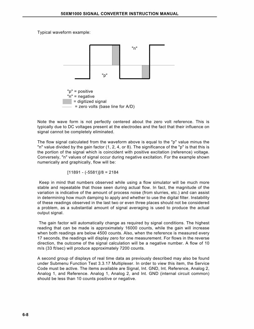
Typical waveform example:
"n"
"p"
"p" = positive"n" = negative = digitized signal = zero volts (base line for A/D)
Note the wave form is not perfectly centered about the zero volt reference. This istypically due to DC voltages present at the electrodes and the fact that their influence onsignal cannot be completely eliminated.
The flow signal calculated from the waveform above is equal to the "p" value minus the"n" value divided by the gain factor (1, 2, 4, or 8). The significance of the "p" is that this isthe portion of the signal which is coincident with positive excitation (reference) voltage.Conversely, "n" values of signal occur during negative excitation. For the example shownnumerically and graphically, flow will be:
[11891 - (-5581)]/8 = 2184
Keep in mind that numbers observed while using a flow simulator will be much morestable and repeatable that those seen during actual flow. In fact, the magnitude of thevariation is indicative of the amount of process noise (from slurries, etc.) and can assistin determining how much damping to apply and whether to use the digital filter. Instabilityof these readings observed in the last two or even three places should not be considereda problem, as a substantial amount of signal averaging is used to produce the actualoutput signal.
The gain factor will automatically change as required by signal conditions. The highestreading that can be made is approximately 16000 counts, while the gain will increasewhen both readings are below 4500 counts. Also, when the reference is measured every17 seconds, the readings will display zero for one measurement. For flows in the reversedirection, the outcome of the signal calculation will be a negative number. A flow of 10m/s (33 ft/sec) will produce approximately 7200 counts.
A second group of displays of real time data as previously described may also be foundunder Submenu Function Test 3.3.17 Multiplexer. In order to view this item, the ServiceCode must be active. The items available are Signal, Int. GND, Int. Reference, Analog 2,Analog 1, and Reference. Analog 1, Analog 2, and Int. GND (internal circuit common)should be less than 10 counts positive or negative.
50XM1000 SIGNAL CONVERTER INSTRUCTION MANUAL
6-8
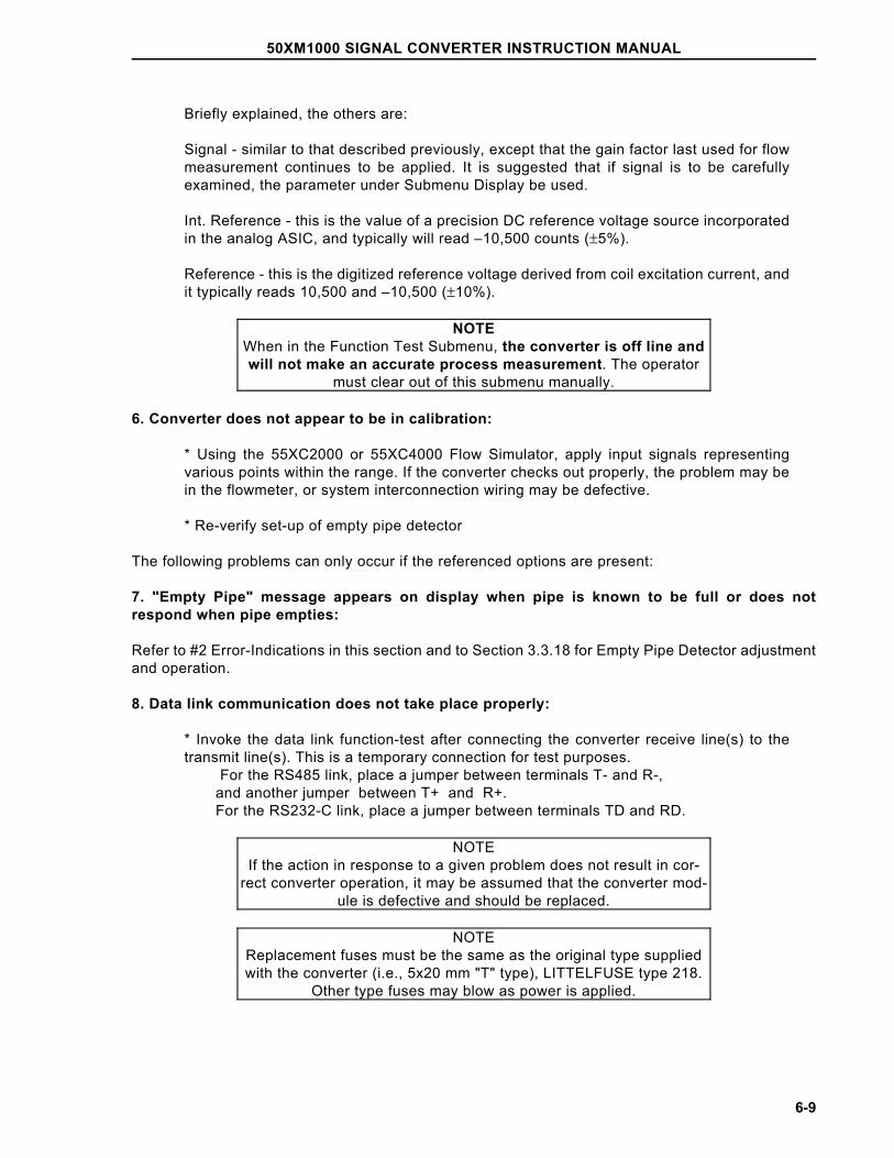
Briefly explained, the others are:
Signal - similar to that described previously, except that the gain factor last used for flowmeasurement continues to be applied. It is suggested that if signal is to be carefullyexamined, the parameter under Submenu Display be used.
Int. Reference - this is the value of a precision DC reference voltage source incorporatedin the analog ASIC, and typically will read –10,500 counts (±5%).
Reference - this is the digitized reference voltage derived from coil excitation current, andit typically reads 10,500 and –10,500 (±10%).
NOTEWhen in the Function Test Submenu, the converter is off line andwill not make an accurate process measurement. The operator
must clear out of this submenu manually.
6. Converter does not appear to be in calibration:
* Using the 55XC2000 or 55XC4000 Flow Simulator, apply input signals representingvarious points within the range. If the converter checks out properly, the problem may bein the flowmeter, or system interconnection wiring may be defective.
* Re-verify set-up of empty pipe detector
The following problems can only occur if the referenced options are present:
7. "Empty Pipe" message appears on display when pipe is known to be full or does notrespond when pipe empties:
Refer to #2 Error-Indications in this section and to Section 3.3.18 for Empty Pipe Detector adjustmentand operation.
8. Data link communication does not take place properly:
* Invoke the data link function-test after connecting the converter receive line(s) to thetransmit line(s). This is a temporary connection for test purposes. For the RS485 link, place a jumper between terminals T- and R-, and another jumper between T+ and R+. For the RS232-C link, place a jumper between terminals TD and RD.
NOTEIf the action in response to a given problem does not result in cor-
rect converter operation, it may be assumed that the converter mod-ule is defective and should be replaced.
NOTEReplacement fuses must be the same as the original type suppliedwith the converter (i.e., 5x20 mm "T" type), LITTELFUSE type 218.
Other type fuses may blow as power is applied.
50XM1000 SIGNAL CONVERTER INSTRUCTION MANUAL
6-9
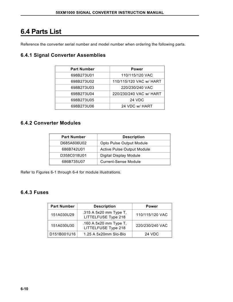
6.4 Parts ListReference the converter serial number and model number when ordering the following parts.
6.4.1 Signal Converter Assemblies
Part Number Power698B273U01 110/115/120 VAC698B273U02 110/115/120 VAC w/ HART698B273U03 220/230/240 VAC698B273U04 220/230/240 VAC w/ HART698B273U05 24 VDC698B273U06 24 VDC w/ HART
6.4.2 Converter Modules
Part Number DescriptionD685A606U02 Opto Pulse Output Module686B742U01 Active Pulse Output Module
D358C018U01 Digital Display Module686B735U07 Current-Sense Module
Refer to Figures 6-1 through 6-4 for module illustrations.
6.4.3 Fuses
Part Number Description Power
151A030U29 .315 A 5x20 mm Type T,LITTELFUSE Type 218 110/115/120 VAC
151A030U30 .160 A 5x20 mm Type T,LITTELFUSE Type 218 220/230/240 VAC
D151B001U16 1.25 A 5x20mm Slo-Blo 24 VDC
50XM1000 SIGNAL CONVERTER INSTRUCTION MANUAL
6-10
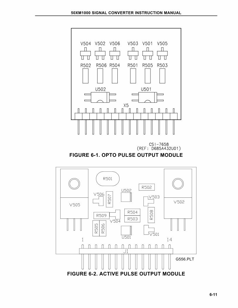
FIGURE 6-1. OPTO PULSE OUTPUT MODULE
FIGURE 6-2. ACTIVE PULSE OUTPUT MODULE
G556.PLT
50XM1000 SIGNAL CONVERTER INSTRUCTION MANUAL
6-11
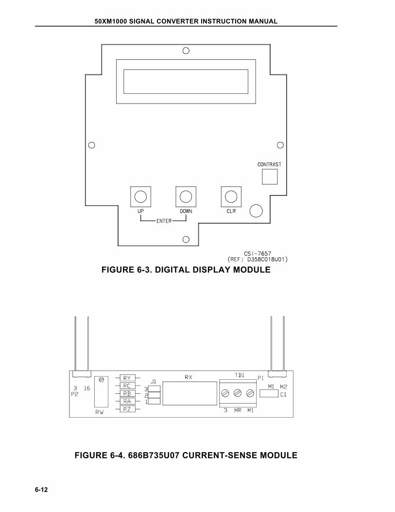
FIGURE 6-3. DIGITAL DISPLAY MODULE
FIGURE 6-4. 686B735U07 CURRENT-SENSE MODULE
50XM1000 SIGNAL CONVERTER INSTRUCTION MANUAL
6-12
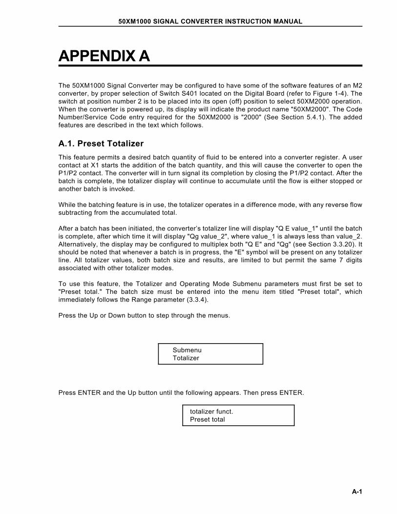
APPENDIX AThe 50XM1000 Signal Converter may be configured to have some of the software features of an M2converter, by proper selection of Switch S401 located on the Digital Board (refer to Figure 1-4). Theswitch at position number 2 is to be placed into its open (off) position to select 50XM2000 operation.When the converter is powered up, its display will indicate the product name "50XM2000". The CodeNumber/Service Code entry required for the 50XM2000 is "2000" (See Section 5.4.1). The addedfeatures are described in the text which follows.
A.1. Preset TotalizerThis feature permits a desired batch quantity of fluid to be entered into a converter register. A usercontact at X1 starts the addition of the batch quantity, and this will cause the converter to open theP1/P2 contact. The converter will in turn signal its completion by closing the P1/P2 contact. After thebatch is complete, the totalizer display will continue to accumulate until the flow is either stopped oranother batch is invoked.
While the batching feature is in use, the totalizer operates in a difference mode, with any reverse flowsubtracting from the accumulated total.
After a batch has been initiated, the converter’s totalizer line will display "Q E value_1" until the batchis complete, after which time it will display "Qg value_2", where value_1 is always less than value_2.Alternatively, the display may be configured to multiplex both "Q E" and "Qg" (see Section 3.3.20). Itshould be noted that whenever a batch is in progress, the "E" symbol will be present on any totalizerline. All totalizer values, both batch size and results, are limited to but permit the same 7 digitsassociated with other totalizer modes.
To use this feature, the Totalizer and Operating Mode Submenu parameters must first be set to"Preset total." The batch size must be entered into the menu item titled "Preset total", whichimmediately follows the Range parameter (3.3.4).
Press the Up or Down button to step through the menus.
SubmenuTotalizer
Press ENTER and the Up button until the following appears. Then press ENTER.
totalizer funct.Preset total
50XM1000 SIGNAL CONVERTER INSTRUCTION MANUAL
A-1
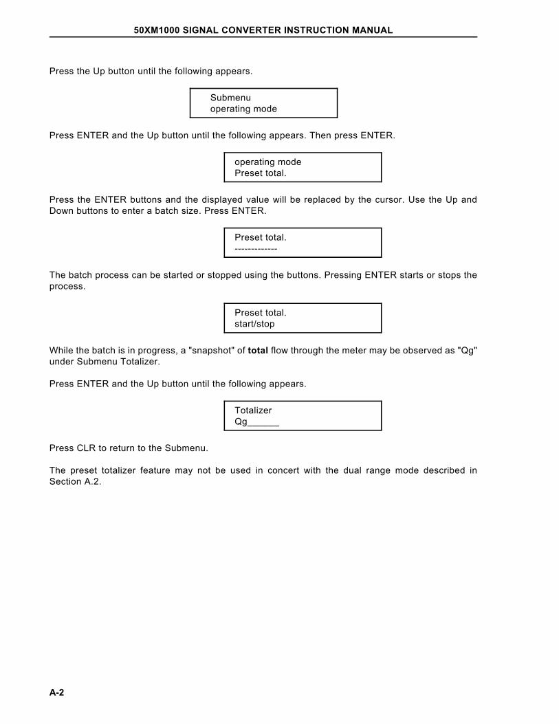
Press the Up button until the following appears.
Submenuoperating mode
Press ENTER and the Up button until the following appears. Then press ENTER.
operating modePreset total.
Press the ENTER buttons and the displayed value will be replaced by the cursor. Use the Up andDown buttons to enter a batch size. Press ENTER.
Preset total.-------------
The batch process can be started or stopped using the buttons. Pressing ENTER starts or stops theprocess.
Preset total.start/stop
While the batch is in progress, a "snapshot" of total flow through the meter may be observed as "Qg"under Submenu Totalizer.
Press ENTER and the Up button until the following appears.
TotalizerQg______
Press CLR to return to the Submenu.
The preset totalizer feature may not be used in concert with the dual range mode described inSection A.2.
50XM1000 SIGNAL CONVERTER INSTRUCTION MANUAL
A-2
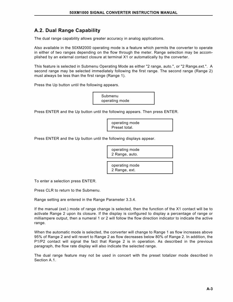
A.2. Dual Range CapabilityThe dual range capability allows greater accuracy in analog applications.
Also available in the 50XM2000 operating mode is a feature which permits the converter to operatein either of two ranges depending on the flow through the meter. Range selection may be accom-plished by an external contact closure at terminal X1 or automatically by the converter.
This feature is selected in Submenu Operating Mode as either "2 range, auto.", or "2 Range,ext.". Asecond range may be selected immediately following the first range. The second range (Range 2)must always be less than the first range (Range 1).
Press the Up button until the following appears.
Submenuoperating mode
Press ENTER and the Up button until the following appears. Then press ENTER.
operating modePreset total.
Press ENTER and the Up button until the following displays appear.
operating mode2 Range, auto.
operating mode2 Range, ext.
To enter a selection press ENTER.
Press CLR to return to the Submenu.
Range setting are entered in the Range Parameter 3.3.4.
If the manual (ext.) mode of range change is selected, then the function of the X1 contact will be toactivate Range 2 upon its closure. If the display is configured to display a percentage of range ormilliampere output, then a numeral 1 or 2 will follow the flow direction indicator to indicate the activerange.
When the automatic mode is selected, the converter will change to Range 1 as flow increases above95% of Range 2 and will revert to Range 2 as flow decreases below 80% of Range 2. In addition, theP1/P2 contact will signal the fact that Range 2 is in operation. As described in the previousparagraph, the flow rate display will also indicate the selected range.
The dual range feature may not be used in concert with the preset totalizer mode described inSection A.1.
50XM1000 SIGNAL CONVERTER INSTRUCTION MANUAL
A-3
A.3. Current-Sense NetworkSome Flowmeter systems used with the 50XM1000 remote Signal Converter do not have a coilcurrent sensing circuit mounted inside their Primary housings. Most such primaries are designed forcontinuous submergence service. In these meters, instead of current sensing being done in thePrimary, a small network is mounted within the remote Signal Converter housing. This network, partnumber 686B735U07, is interposed between the primary coil leads "M1" and "MR" and the converterterminals "3", "16", "M1", and "M2" (Refer to Figures 2-13 & 7-4). The network has been calibratedby the factory so that the system achieves the proper Cal Factor. Do not make any adjustments tothe Current-Sense module.
Excitation currents between 80 and 550 mA may be set using the moveable jumper (J1) andpotentiometer (RW) on the 686B735U07 module. Proper adjustment of a replacement assemblyrequires the use of a precision constant-current source and low level digital voltmeter. Replacementunits ordered from the factory are preset if the system serial number is provided. Consult TechSupport if more information regarding this circuit is required.
50XM1000 SIGNAL CONVERTER INSTRUCTION MANUAL
A-4

ABB (www.abb.com) is a leader in power and automationtechnologies that enable utility and industry customers to improveperformance while lowering environmental impact. The ABB Groupof companies operates in around 100 countries and employs about105,000 people.
www.abb.com/instrumentation
The Company’s policy is one of continuous productimprovement and the right is reserved to modify theinformation contained herein without notice.
Printed in USA (January, 2005] © ABB 2005
Germany UK Italy USA China
ABB AutomationProducts GmbHBorsigstr. 263755 AlzenauTel: +49 (0) 6196 800 0Fax: +49 (0) 6196 800 1849
ABB LtdOldends Lane, StonehouseGloucestershire GL 10 3TA
Tel. +44 (0) 1453 826 661FAX: +44 (0) 1453 829 671
ABB SACE S.p.AVia Statale 11320016 Lenno (CO)
Tel: +39 0344 58111Fax: +39 0344 56278
ABB Inc.125 East County Line RoadWarminster, PA 18974-4995
Tel: +1 215 674 6000FAX: +1 215 674 7183
ABB (China) Ltd38th Floor Raffles City (Office Tower)268 Xizang Zhong LuShanghai 200001Tel: +86 (0)21 61228888FAX: +86 (0)21 61228892
PN25
041B