Embed Size (px)
Citation preview
Unit–I : Image Drafting
COREL DRAW
Introduction – Create drawing- Multi-page documents- Introduction to Objects-
Duplicating and Cloning objects - Transforming objects- Drawing Objects- Using the
drawing tools- Working With lines, Outlines and Brush Strokes – Drawing Shapes –
Working With Objects – Shaping Objects – Working With Symbols – Filling Objects.
Unit–II : Image Effects
Understanding Bezier - Using styles and presets - Creating style formats - Text
Special Effects and Output - Selecting and applying outlines - Advanced
typographical controls -Special effects with text - Placing text on a path - Adding
perspective to objects - lens effects, blend, extrude and contour- Working With
Colors – Managing Color for Display, Input, and Output – Adding three Dimensional
Effects to Objects – Change the Transparency of Objects – Using Lenses with
Object.
Unit–III : Layers
Working With Pages – Working With Layers – Adding and Formatting Text –
Working with Asian Text – Managing Fonts – Using Writing Tools - Guide Manager-
Manipulating objects- Aligning objects- Filling objects with colours and patterns-
Editing Objects- Using the Transform Roll-Up-Combining - Scaling- Welding-
Intersecting and Trimming objects- Converting straight-edged objects into Curved
objects.
Unit–IV : Bitmaps
Introduction-Raster vs. Bitmaps- Working With bitmaps – Tracing bitmaps and
editing traced results – Changing the color mode of bit maps – Creating Web-
enabled objects –Web Publishing – Printing – File Formats – Working With Graphic
text and color styles.
Unit–V : Image Corrections
Working with spot and process color- Using the interactive fill tools- Working
with Pantone colors-Customizing CorelDraw- Creating your own palettes-
Applications of Corel draw -Printing from CorelDraw- Pre-flight checklist -Logo
Creation – Concept Creation – Portfolio creation.
2
Introduction
CorelDraw is a vector illustration program. Images are displayed on the computer
screen as pixels. How the program treats the pixels is determined by whether the
image is defined as a vector or a bitmap. A bitmap file defines the position, color and
size of each pixel. A vector program defines a line of pixels and treats them as a
single object. To change an object in a bitmap, you must change all the pixels, so if a
red box on a blue background needs to be smaller, you have to re-create a smaller
red box and change the pixels where the box was to the blue background. When you
have a vector image, you redefine the size and location of the lines. Each object is
independent of the others and can be manipulated as needed. To make your work
easier, Corel Corporation has added a few bitmap manipulation tools in DRAW and
includes its bitmap manipulation program, CorelPhotoPaint.
CorelDraw is one of the most powerful and versatile illustration programs on the
market today, on any platform. I cannot teach you all you can do with this program; I
can only show you how to use the tools and effects given in this program. What you
do with CorelDraw is limited only by your imagination, time, and budget. In my
personal experience, I have seen projects ranging from fine art frescoes to silk-
screened T-shirts to laser engraved stainless steel parts. Your use may be as
ordinary as a poster for a sale or as complex as the annual report for a Fortune 500
company. From desktop publishing to fine art, CorelDraw gives you the tools. I can
only teach you the skills to use them. The talent, inspiration and effort has to come
from you.
Setting up a Page
3
Pages in a CorelDraw document can have a mixed orientation. Some can be portrait
and some can be landscape. In these exercises, you will explore the various options
on the Page setup up dialog. When you print the document, CorelDraw will adjust
the orientation so the page prints properly, in other words, you will see the pages as
mixed orientation but they will print with the all pages rotated to either landscape or
portrait.
Go to the Standard Toolbar and select the new button.
Or use (Crtl+N) or the button on the Standard toolbar.
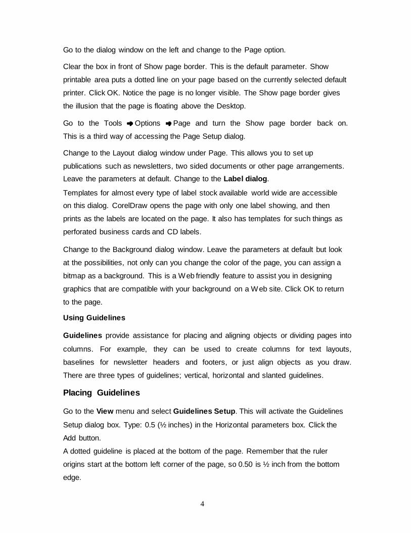
Go to the Property Bar and choose the Landscape button.
Notice the two buttons to the right of the Landscape button. When the icon at the top
is pressed, the page orientation change applies to all pages of the document. When
the lower icon is depressed, the change is applied only to the active page. In other
words, if you add a page when the bottom icon is depressed, that page will be
portrait, not landscape.
Go to the Layout menu and select Page Setup. This activates the Page Size
dialog box within the Options dialog. You can also double-click on the page border
in the drawing area to activate the Page Size dialog box.
Change the orientation to Portrait. Notice the preview window that shows your
changes.
Click and drop-down the Paper menu and explore the various sizes of paper
available. If you choose the Custom size, you can set a specific page size then save
that size for future projects. Notice the option to apply the change only to the current
page of the document.
4
Go to the dialog window on the left and change to the Page option.
Clear the box in front of Show page border. This is the default parameter. Show
printable area puts a dotted line on your page based on the currently selected default
printer. Click OK. Notice the page is no longer visible. The Show page border gives
the illusion that the page is floating above the Desktop.
Go to the Tools Options Page and turn the Show page border back on.
This is a third way of accessing the Page Setup dialog.
Change to the Layout dialog window under Page. This allows you to set up
publications such as newsletters, two sided documents or other page arrangements.
Leave the parameters at default. Change to the Label dialog.
Templates for almost every type of label stock available world wide are accessible
on this dialog. CorelDraw opens the page with only one label showing, and then
prints as the labels are located on the page. It also has templates for such things as
perforated business cards and CD labels.
Change to the Background dialog window. Leave the parameters at default but look
at the possibilities, not only can you change the color of the page, you can assign a
bitmap as a background. This is a Web friendly feature to assist you in designing
graphics that are compatible with your background on a Web site. Click OK to return
to the page.
Using Guidelines
Guidelines provide assistance for placing and aligning objects or dividing pages into
columns. For example, they can be used to create columns for text layouts,
baselines for newsletter headers and footers, or just align objects as you draw.
There are three types of guidelines; vertical, horizontal and slanted guidelines.
Placing Guidelines
Go to the View menu and select Guidelines Setup. This will activate the Guidelines
Setup dialog box. Type: 0.5 (½ inches) in the Horizontal parameters box. Click the
Add button.
A dotted guideline is placed at the bottom of the page. Remember that the ruler
origins start at the bottom left corner of the page, so 0.50 is ½ inch from the bottom
edge.
5
Type: 10.5 (10 ½ inches) in the Horizontal position text box.
Notice that the position of the guidelines displays as you place them. If you want to
change the position of a guideline, highlight it, change the measurement, and then
click Move. Click Add.
Do not use the Return (Enter) key. This will close the box without adding the
guideline.
Click on the Vertical tab and set two guidelines at one half inch from the sides of the
page. Activate the Snap to Guidelines.
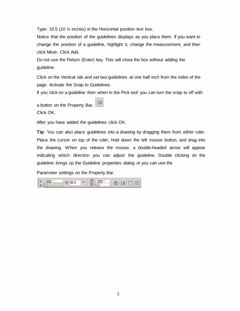
If you click on a guideline then when in the Pick tool' you can turn the snap to off with
a button on the Property Bar.
Click OK.
After you have added the guidelines click OK.
Tip: You can also place guidelines into a drawing by dragging them from either ruler.
Place the cursor on top of the ruler, hold down the left mouse button, and drag into
the drawing. When you release the mouse, a double-headed arrow will appear
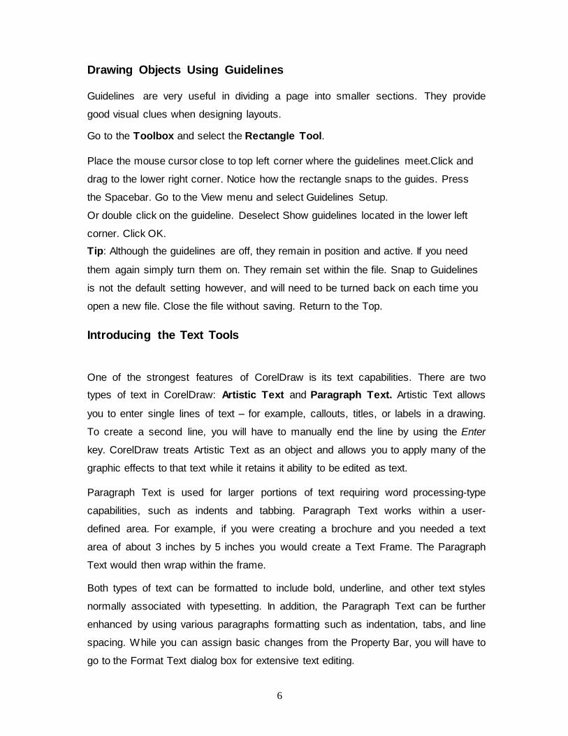
indicating which direction you can adjust the guideline. Double clicking on the
guideline brings up the Guideline properties dialog or you can use the
Parameter settings on the Property Bar.
6
Drawing Objects Using Guidelines
Guidelines are very useful in dividing a page into smaller sections. They provide
good visual clues when designing layouts.
Go to the Toolbox and select the Rectangle Tool.
Place the mouse cursor close to top left corner where the guidelines meet.Click and
drag to the lower right corner. Notice how the rectangle snaps to the guides. Press
the Spacebar. Go to the View menu and select Guidelines Setup.
Or double click on the guideline. Deselect Show guidelines located in the lower left
corner. Click OK.
Tip: Although the guidelines are off, they remain in position and active. If you need
them again simply turn them on. They remain set within the file. Snap to Guidelines
is not the default setting however, and will need to be turned back on each time you
open a new file. Close the file without saving. Return to the Top.
Introducing the Text Tools
One of the strongest features of CorelDraw is its text capabilities. There are two
types of text in CorelDraw: Artistic Text and Paragraph Text. Artistic Text allows
you to enter single lines of text – for example, callouts, titles, or labels in a drawing.
To create a second line, you will have to manually end the line by using the Enter
key. CorelDraw treats Artistic Text as an object and allows you to apply many of the
graphic effects to that text while it retains it ability to be edited as text.
Paragraph Text is used for larger portions of text requiring word processing-type
capabilities, such as indents and tabbing. Paragraph Text works within a user-
defined area. For example, if you were creating a brochure and you needed a text
area of about 3 inches by 5 inches you would create a Text Frame. The Paragraph
Text would then wrap within the frame.
Both types of text can be formatted to include bold, underline, and other text styles
normally associated with typesetting. In addition, the Paragraph Text can be further
enhanced by using various paragraphs formatting such as indentation, tabs, and line
spacing. While you can assign basic changes from the Property Bar, you will have to
go to the Format Text dialog box for extensive text editing.

Another feature of the Text Tool is the real-time spell checking utility. It functions
very similarly to that in most word processors. There is also a Grammar checker
available but it is not turned on as a default. If there is a spelling error you will see a
red line appear under the text as you type. This means that the word is misspelled
according to the default dictionary. A blue line indicates a word not in the dictionary
but you have told the program to ignore. You can add technical words to the
dictionary using the Spell Check dialog box.
Adding Artistic Text
Go to the File menu and choose Open (4th at the bottom of the menu).
The most recent files you have worked on will be listed at the end of this menu. You
can change the number of files listed in the Options dialog.
Select all the boxes.
Go to the Property Bar Ungroup All.
Go to the Toolbox Text Tool.
Click in the blank area to the left of the page.
This places an insertion point where the text will be placed.
Go to the Text menu Format Text.
Or the F on the Property Bar or (Ctrl+T). This activates the Format Text dialog box
used for setting text options.
Scroll down in the Font list Times New Roman.
If you know the name of the font you are looking for, highlight the first font name,
then type the first letter of the font you want. The list will automatically scroll to the
fonts that begin with that letter.
Replace the current font size value with 14.
Go to the Weight drop-down list and select Bold.
As you make changes they appear in the sample window at the bottom of the dialog
box it will display the first few words of anything you have typed or the first few letters
of the alphabet. Click OK.
If you have not set an insertion point, the change default dialog box will appear. If
8
you click OK at this point, the next time you access the Text tool, it will have these
settings.
Creating Labels
Type: Organization Chart for LaSalle Produce Company. Right click on the word
LaSalle and choose Ignore All. The red underline turns to blue. You can add to your
dictionary any words you know you will be using often. Press Enter.
Use the following list to complete the titles for the left group.
Press the Enter key after each to place each title on a new line.
Corporate
Sales
Marketing
Advertising.
Go to the Toolbox and select the Pick Tool. This will end the typing mode. The text
will become selected. To toggle to the Pick Tool, use Ctrl+Space bar.
Go to the Arrange menu and select Break Apart. This will split the text into
individual text lines. They can now be moved into position. Copying text properties
Go to the Toolbox and select the Text Tool. Notice the Property Bar. The text
settings reverted back to the default parameter. Click in a blank area below the text
you just typed. Use the following list to complete the titles for the right group.
Press the Enter key after each to place each title on a new line.
Orchard Mgmt
Quality Control
Shipping.
Go to the Toolbox and select the Pick Tool. Selection handles appear.
Go to the Edit menu and select Copy Properties From. This activates the Copy
Properties dialog box. Select Text Properties. Click OK.
Click on any text object from the previous text list with the large black arrow.
The fonts should be updated to match the first list.
Go to the Arrange menu and select Break Apart (Ctrl+K).
9
Place the title of the chart on top and a division title in each box.
Drag one of the corner handles to resize the text.
Artistic Text can be proportionally resized just like other objects. While this is quicker,
it is not as precise as using the Text Format dialog box or the Property Bar.
Reposition the title in the middle over the top of the chart.
Save your work (Ctrl+S).
Tip: A faster way to copy the properties is the Drag and Copy mentioned earlier.
Select the object you wish to copy properties from. With the Right Mouse button,
drag the object to the object you wish to change. A target helps you select the object
to be changed. Release the Mouse. A dialog allows you to choose which properties
you want to apply. The original object remains in place, unchanged.
Aligning Text within an Object
The most important thing to remember when aligning objects is the selection order.
Remember that alignment is based on the last object selected.
Select the text in the top box (Corporate).
Check the Status Bar to ensure that you have the text.
Hold down the Shift key.
Select the white box below the text.
The Status Bar should read that you have two objects.
Release the Shift key.
Press the e key and then the c key.
The short cut will center the two objects vertically and horizontally with each other.
Two or more objects must be selected, or, go to the Arrange menu and select Align
and distribute. Select both the Center options. Selecting the Center of the Page
option, then deselecting it accomplishes the same thing. Click OK.
This will place the text in the center of the boxes.
Repeat these steps to align the rest of the text with the boxes as needed.
Remember to select the text first.
Save your work (Ctrl+S).
Adding Paragraph Text
10
Paragraph Text is created by drawing an area for the text. The technique is similar to
drawing a rectangle. The area used by Paragraph Text is referred to as a Text
Frame. It acts like a small page.
Go to the Toolbox and select the Text Tool.
Click and drag in a blank area of the page to create a Text Frame approximately 3
inches wide and 3.5 inches tall.
As you drag, watch the Status Bar for dimensions. Text Frames can be resized after
they are created so you don't have to be exact.
Release the mouse button.
Go to the Text menu and select Format Text.
Or use the Property Bar.
Set the Font to Arial and the Size to 14 points.
One point is equal to 1/72 inch.
Click OK.
Type:
The LaSalle Citrus organization was established in 1915 by its owner, Lee Mone
Peel. A French immigrant, Mr. Peel purchased a tract of land in south Texas and
began growing citrus produce. It has since grown to be the nation's thirtieth largest
grower.
Click Ignore All for both LaSalle and Mone when the spelling checker underlines
them.
Go to the Toolbox and select the Pick Tool.
Selection handles should appear around the Paragraph Text. If they do not, then
select the Text Frame.
Move the text under the right side column of boxes.
Save the file.
Importing Files
Many file types can be opened with CorelDraw. When you open the Import dialog,
the Files Type drop-down list will show you the various kinds of files available. The
filters to import these files are installed with DRAW. If you do not see a file type you
need, do a custom install from the CD-ROM. Check the list of files to see if a filter is
available and follow the directions to install it. Importing files makes a copy of the file
within DRAW. It does not affect the original file. Go to the File menu Import.
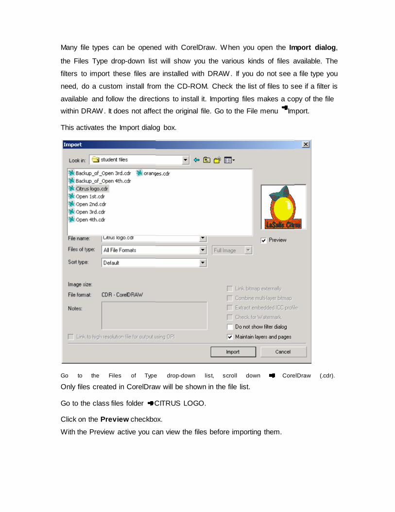
This activates the Import dialog box.
Go to the Files of Type drop-down list, scroll down CorelDraw (.cdr).
Only files created in CorelDraw will be shown in the file list.
Go to the class files folder CITRUS LOGO.
Click on the Preview checkbox.
With the Preview active you can view the files before importing them.
12
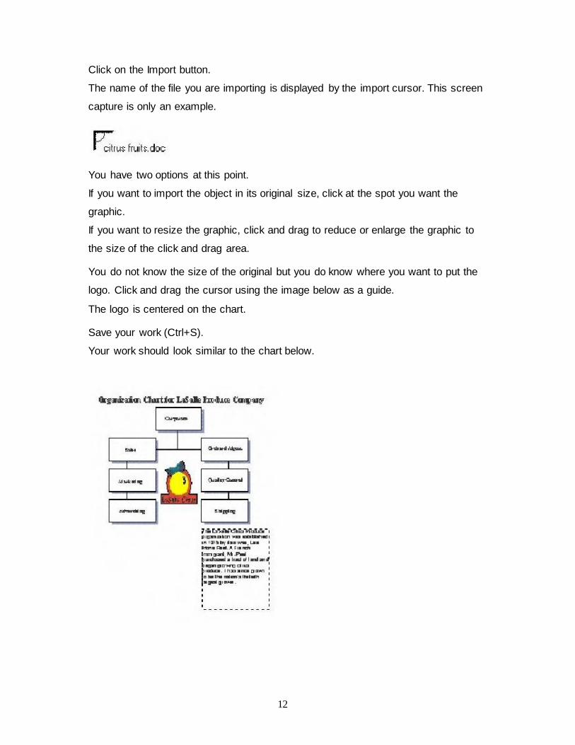
Click on the Import button.
The name of the file you are importing is displayed by the import cursor. This screen
capture is only an example.
You have two options at this point.
If you want to import the object in its original size, click at the spot you want the
graphic.
If you want to resize the graphic, click and drag to reduce or enlarge the graphic to
the size of the click and drag area.
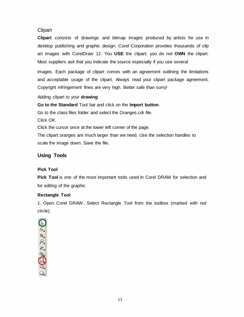
You do not know the size of the original but you do know where you want to put the
logo. Click and drag the cursor using the image below as a guide.
The logo is centered on the chart.
Save your work (Ctrl+S).
Your work should look similar to the chart below.
13
Clipart
Clipart consists of drawings and bitmap images produced by artists for use in
desktop publishing and graphic design. Corel Corporation provides thousands of clip
art images with CorelDraw 12. You USE the clipart; you do not OWN the clipart.
Most suppliers ask that you indicate the source especially if you use several
images. Each package of clipart comes with an agreement outlining the limitations
and acceptable usage of the clipart. Always read your clipart package agreement.
Copyright infringement fines are very high. Better safe than sorry!
Adding clipart to your drawing
Go to the Standard Tool bar and click on the Import button.
Go to the class files folder and select the Oranges.cdr file.
Click OK.
Click the cursor once at the lower left corner of the page.
The clipart oranges are much larger than we need. Use the selection handles to
scale the image down. Save the file.
Using Tools
Pick Tool
Pick Tool is one of the most important tools used in Corel DRAW for selection and
for editing of the graphic.
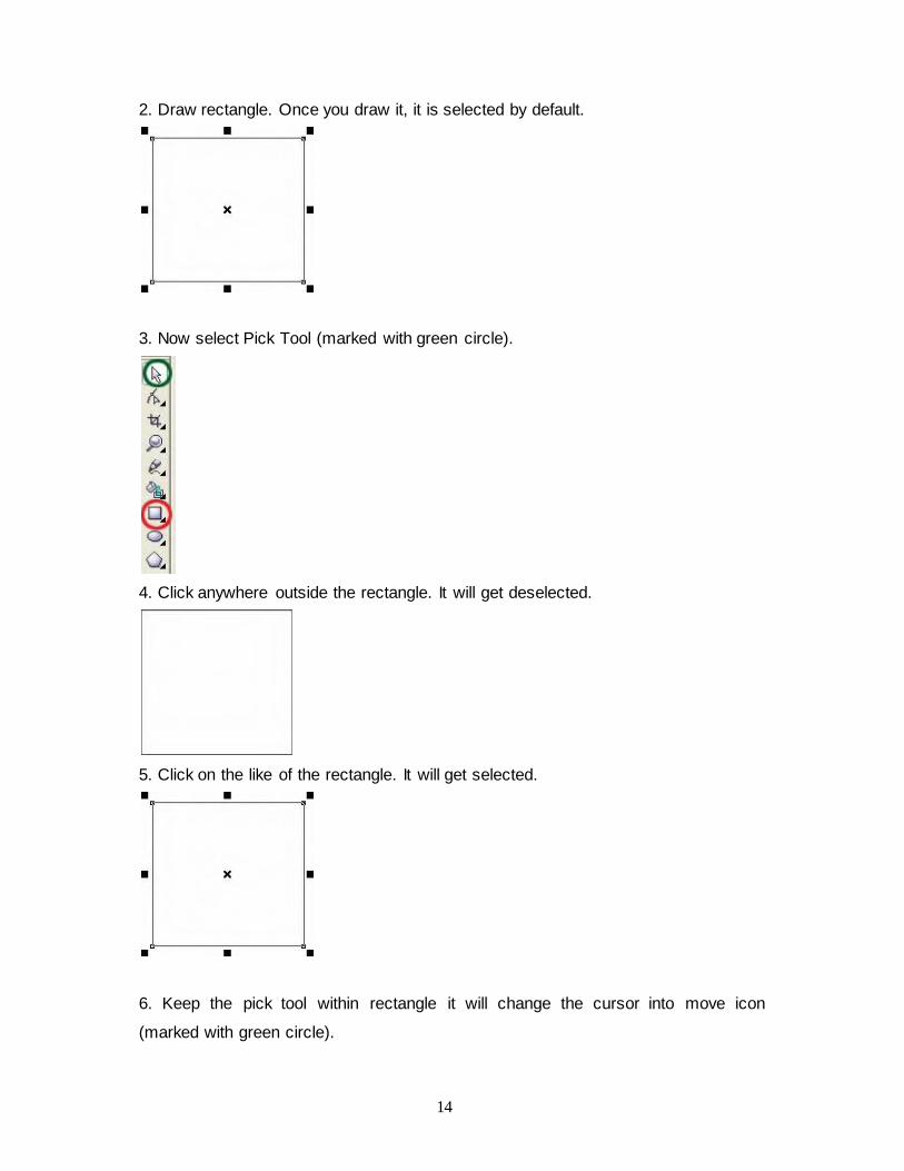
Rectangle Tool
1. Open Corel DRAW. Select Rectangle Tool from the toolbox (marked with red
circle).
14
2. Draw rectangle. Once you draw it, it is selected by default.
3. Now select Pick Tool (marked with green circle).
4. Click anywhere outside the rectangle. It will get deselected.
5. Click on the like of the rectangle. It will get selected.
6. Keep the pick tool within rectangle it will change the cursor into move icon
(marked with green circle).
15
7. Press and drag the mouse button to move the rectangle.
Interactive Blend Tool
Let us start with the first effect in CorelDraw. Interactive Blend Tool blends two
objects. We are learning just the basics about blend effect in this lesson. There are
lots of details which will be covered in the advanced level.
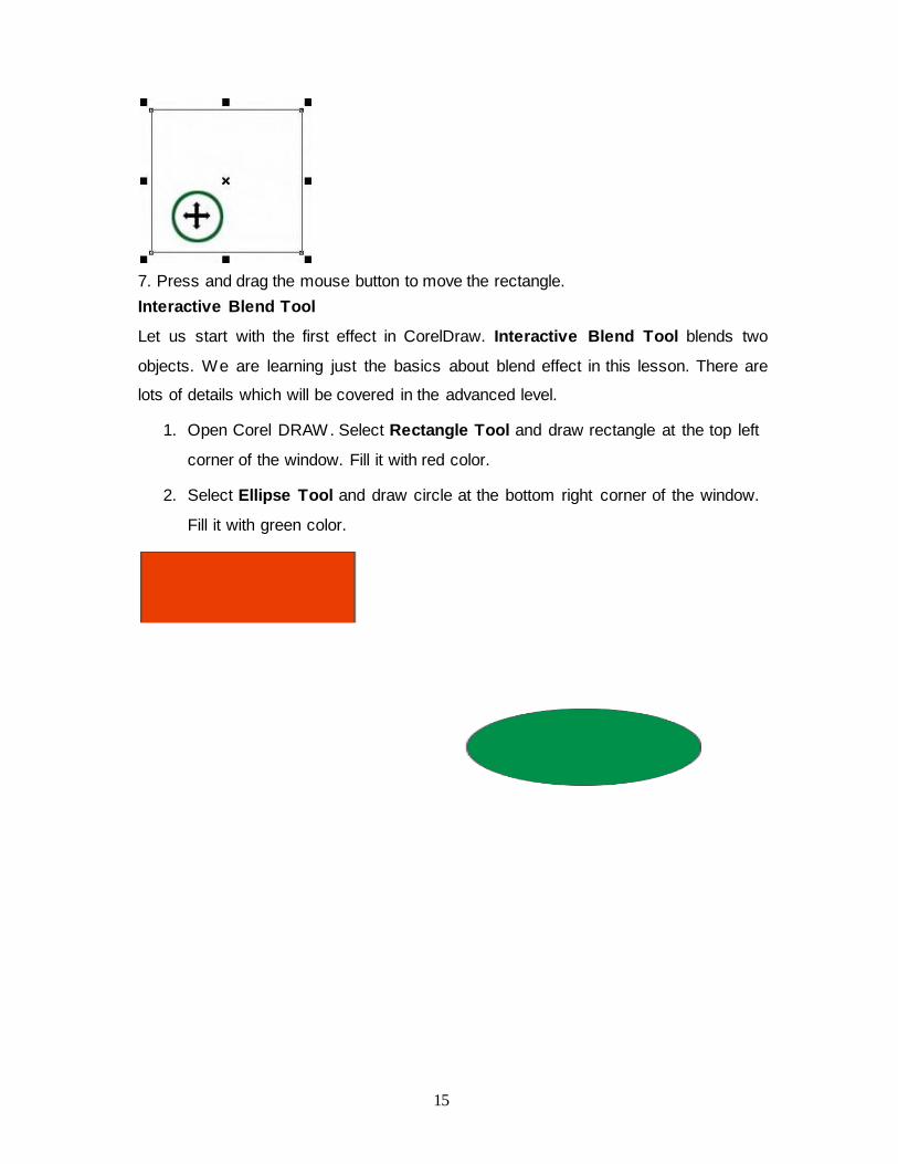
1. Open Corel DRAW. Select Rectangle Tool and draw rectangle at the top left
corner of the window. Fill it with red color.
2. Select Ellipse Tool and draw circle at the bottom right corner of the window.
Fill it with green color.
16
3. Select Interactive Blend Tool (marked with green circle).
4. Now please observe the changes in the cursor carefully.
5. Move the cursor inside the red rectangle. There is a difference between the cursor
outside and inside the rectangle.
6. Once the cursor is changed when it is inside the red rectangle, press and drags it.
Take it to the inside area of the green circle.
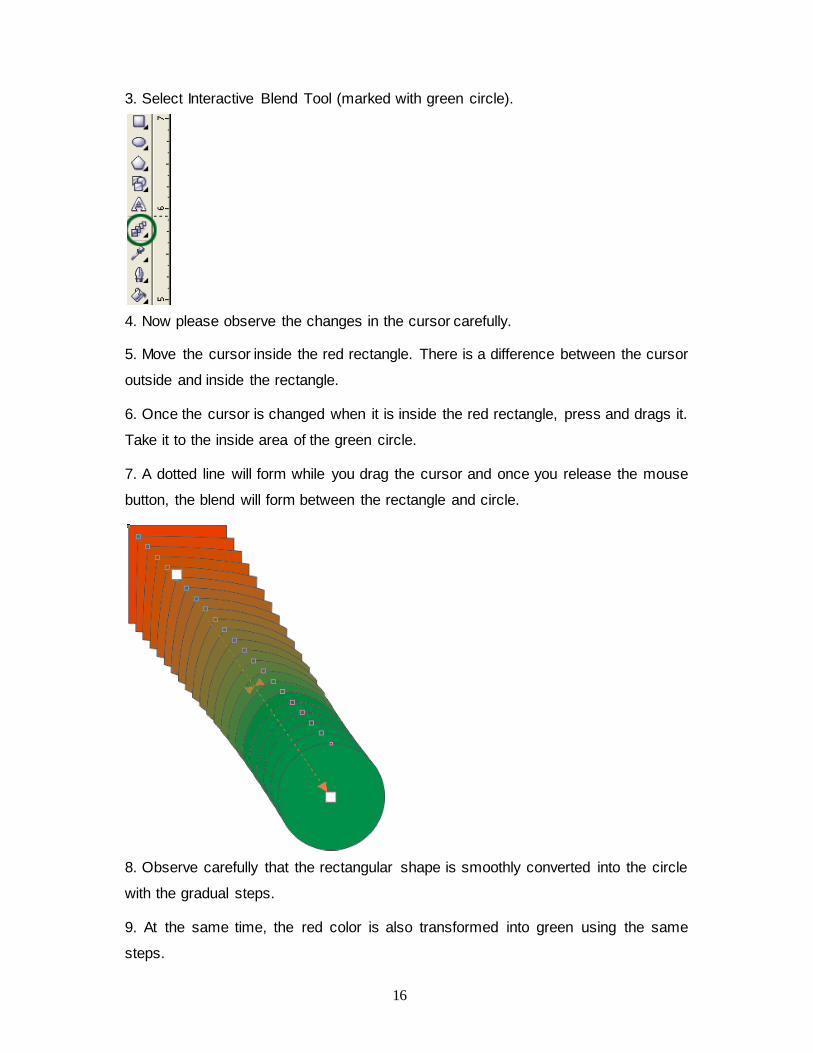
7. A dotted line will form while you drag the cursor and once you release the mouse
button, the blend will form between the rectangle and circle.
8. Observe carefully that the rectangular shape is smoothly converted into the circle
with the gradual steps.
9. At the same time, the red color is also transformed into green using the same
steps.
17
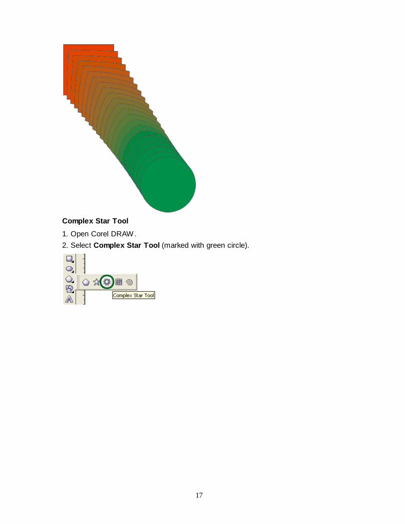
Complex Star Tool
1. Open Corel DRAW.
2. Select Complex Star Tool (marked with green circle).
18
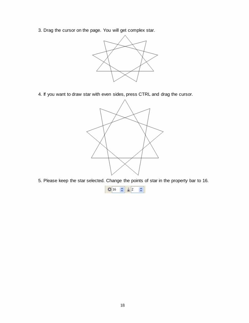
3. Drag the cursor on the page. You will get complex star.
4. If you want to draw star with even sides, press CTRL and drag the cursor.
5. Please keep the star selected. Change the points of star in the property bar to 16.
19
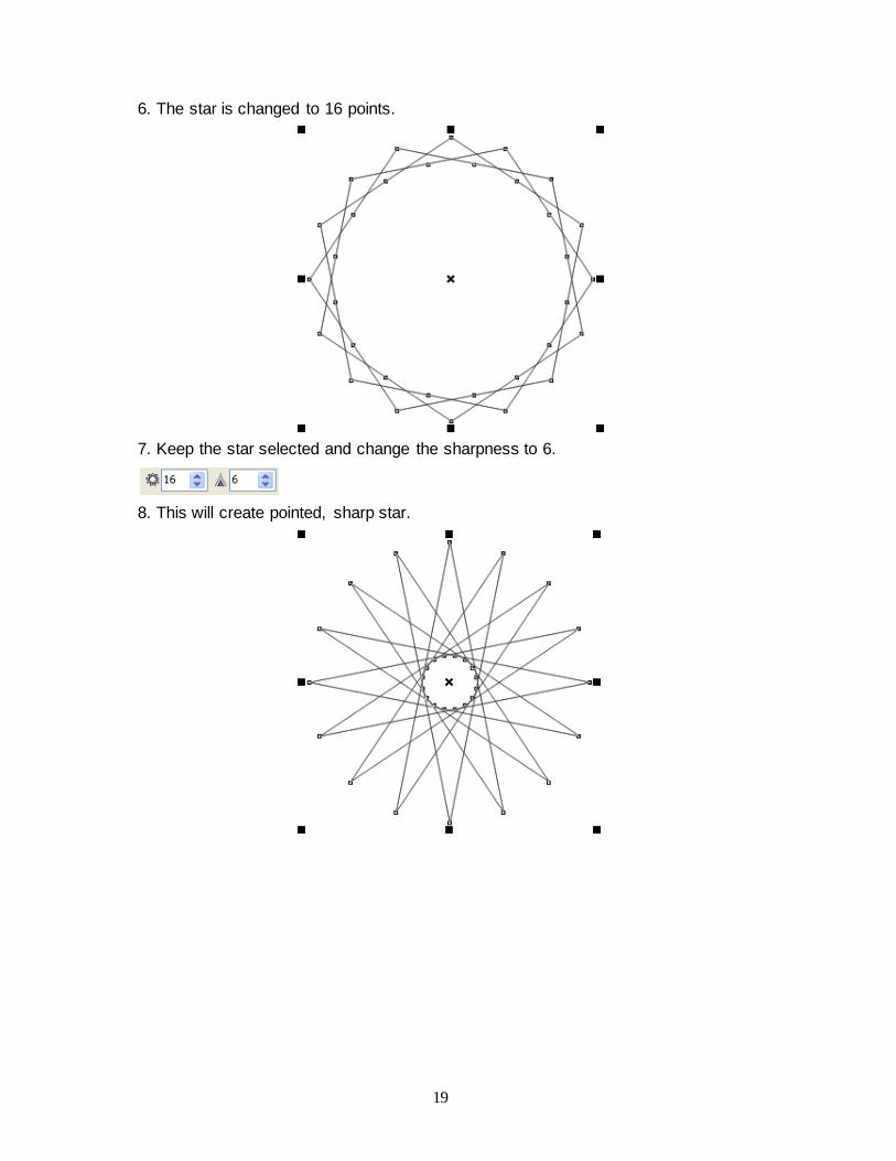
6. The star is changed to 16 points.
7. Keep the star selected and change the sharpness to 6.
8. This will create pointed, sharp star.
20
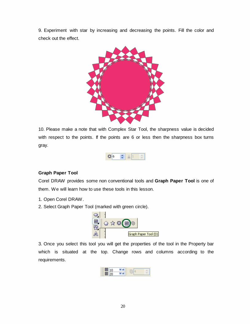
9. Experiment with star by increasing and decreasing the points. Fill the color and
check out the effect.
10. Please make a note that with Complex Star Tool, the sharpness value is decided
with respect to the points. If the points are 6 or less then the sharpness box turns
gray.
Graph Paper Tool
Corel DRAW provides some non conventional tools and Graph Paper Tool is one of
them. We will learn how to use these tools in this lesson.
1. Open Corel DRAW.
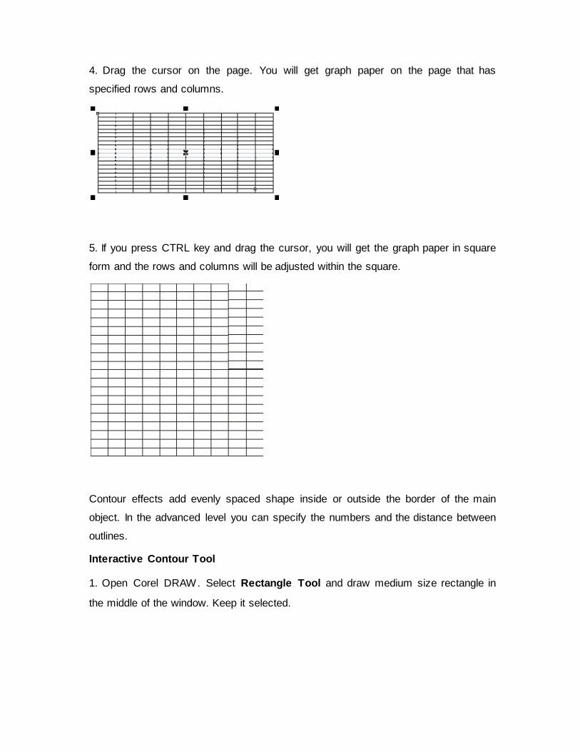
2. Select Graph Paper Tool (marked with green circle).
3. Once you select this tool you will get the properties of the tool in the Property bar
which is situated at the top. Change rows and columns according to the
requirements.
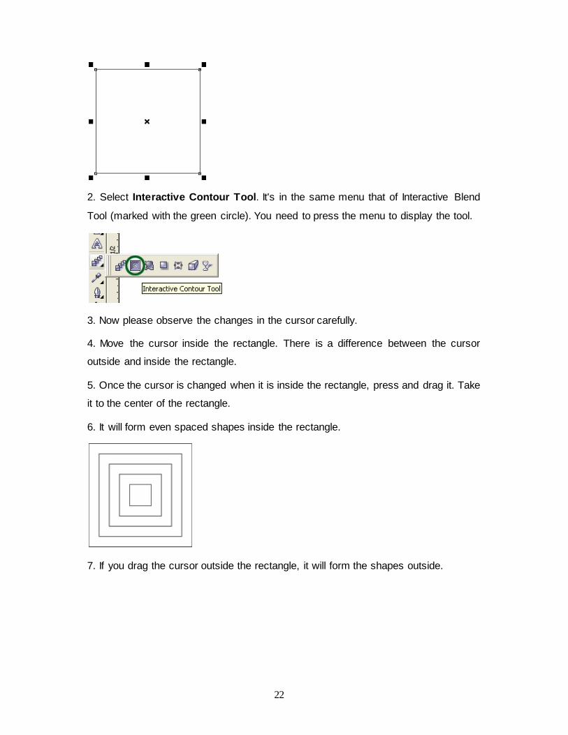
4. Drag the cursor on the page. You will get graph paper on the page that has
specified rows and columns.
5. If you press CTRL key and drag the cursor, you will get the graph paper in square
form and the rows and columns will be adjusted within the square.
Contour effects add evenly spaced shape inside or outside the border of the main
object. In the advanced level you can specify the numbers and the distance between
outlines.
Interactive Contour Tool
1. Open Corel DRAW. Select Rectangle Tool and draw medium size rectangle in
the middle of the window. Keep it selected.
22
2. Select Interactive Contour Tool. It's in the same menu that of Interactive Blend
Tool (marked with the green circle). You need to press the menu to display the tool.
3. Now please observe the changes in the cursor carefully.
4. Move the cursor inside the rectangle. There is a difference between the cursor
outside and inside the rectangle.
5. Once the cursor is changed when it is inside the rectangle, press and drag it. Take
it to the center of the rectangle.
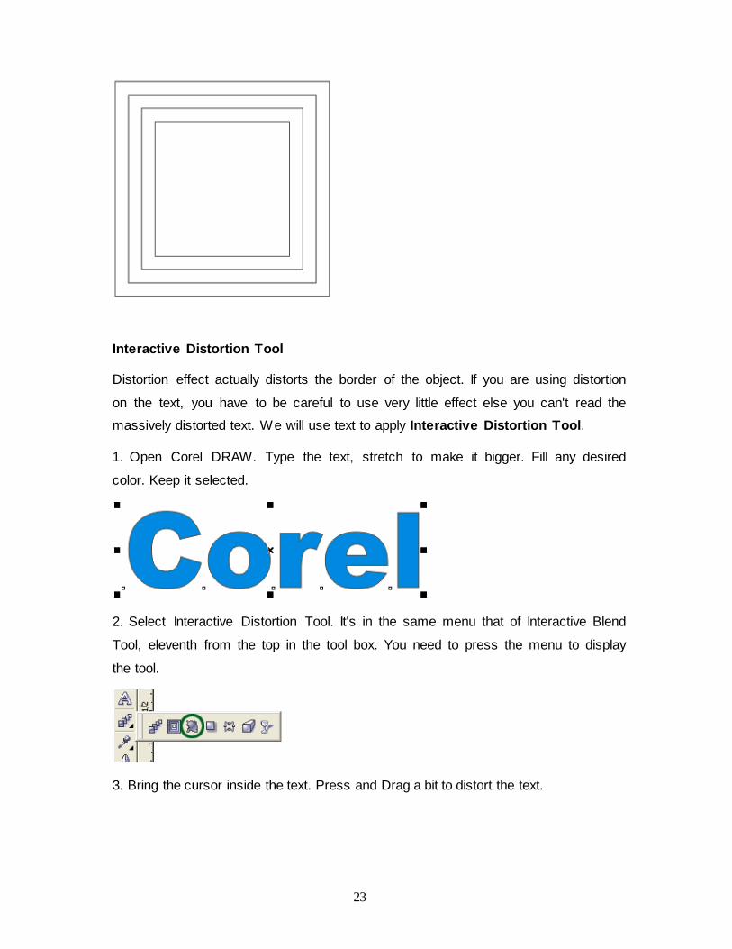
6. It will form even spaced shapes inside the rectangle.
7. If you drag the cursor outside the rectangle, it will form the shapes outside.
23
Interactive Distortion Tool
Distortion effect actually distorts the border of the object. If you are using distortion
on the text, you have to be careful to use very little effect else you can't read the
massively distorted text. We will use text to apply Interactive Distortion Tool.
1. Open Corel DRAW. Type the text, stretch to make it bigger. Fill any desired
color. Keep it selected.
2. Select Interactive Distortion Tool. It's in the same menu that of Interactive Blend
Tool, eleventh from the top in the tool box. You need to press the menu to display
the tool.
3. Bring the cursor inside the text. Press and Drag a bit to distort the text.
24
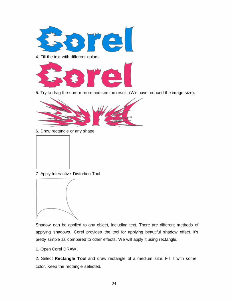
4. Fill the text with different colors.
5. Try to drag the cursor more and see the result. (We have reduced the image size).
6. Draw rectangle or any shape.
7. Apply Interactive Distortion Tool
Shadow can be applied to any object, including text. There are different methods of
applying shadows. Corel provides the tool for applying beautiful shadow effect. It's
pretty simple as compared to other effects. We will apply it using rectangle.
1. Open Corel DRAW.
2. Select Rectangle Tool and draw rectangle of a medium size. Fill it with some
color. Keep the rectangle selected.
25
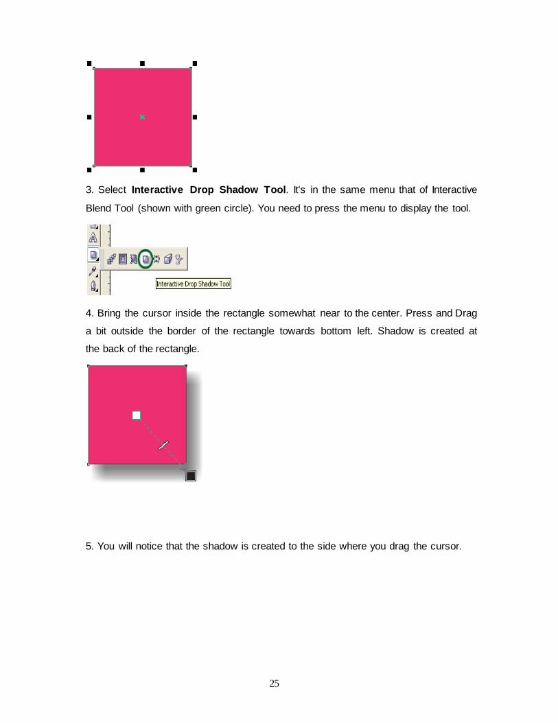
3. Select Interactive Drop Shadow Tool. It's in the same menu that of Interactive
Blend Tool (shown with green circle). You need to press the menu to display the tool.
4. Bring the cursor inside the rectangle somewhat near to the center. Press and Drag
a bit outside the border of the rectangle towards bottom left. Shadow is created at
the back of the rectangle.
5. You will notice that the shadow is created to the side where you drag the cursor.

26
6. Draw any shape and apply Interactive Drop Shadow Tool.
It is an interesting effect where you can stretch and compress the object using eight
available points and give desired shape to the object. We will apply this effect on the
text.
Text Tool
1. Open Corel DRAW.
2. Select Text Tool. Type something, stretch it to bigger size, fill any color and keep
it selected.
3. Select Interactive Envelope Tool. It's in the same menu that of Interactive Blend
Tool (shown with green circle). You need to press the menu to display the tool.
4. Once you select Interactive Envelope Tool, the text will display dotted line
around it with eight points.
27
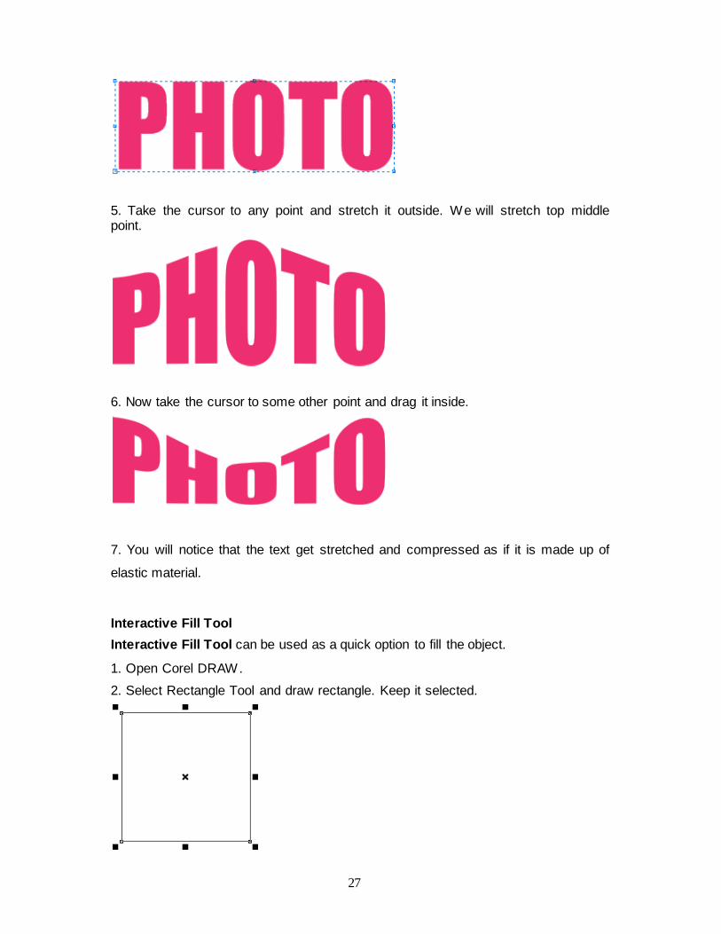
5. Take the cursor to any point and stretch it outside. We will stretch top middle point.
6. Now take the cursor to some other point and drag it inside.
7. You will notice that the text get stretched and compressed as if it is made up of
elastic material.
Interactive Fill Tool
Interactive Fill Tool can be used as a quick option to fill the object.
1. Open Corel DRAW.
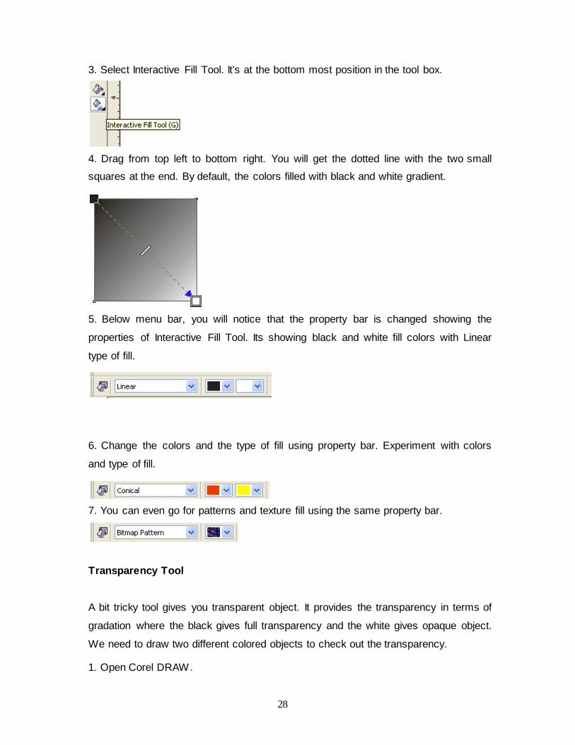
2. Select Rectangle Tool and draw rectangle. Keep it selected.
28
3. Select Interactive Fill Tool. It's at the bottom most position in the tool box.
4. Drag from top left to bottom right. You will get the dotted line with the two small
squares at the end. By default, the colors filled with black and white gradient.
5. Below menu bar, you will notice that the property bar is changed showing the
properties of Interactive Fill Tool. Its showing black and white fill colors with Linear
type of fill.
6. Change the colors and the type of fill using property bar. Experiment with colors
and type of fill.
7. You can even go for patterns and texture fill using the same property bar.
Transparency Tool
A bit tricky tool gives you transparent object. It provides the transparency in terms of
gradation where the black gives full transparency and the white gives opaque object.
We need to draw two different colored objects to check out the transparency.
1. Open Corel DRAW.
29
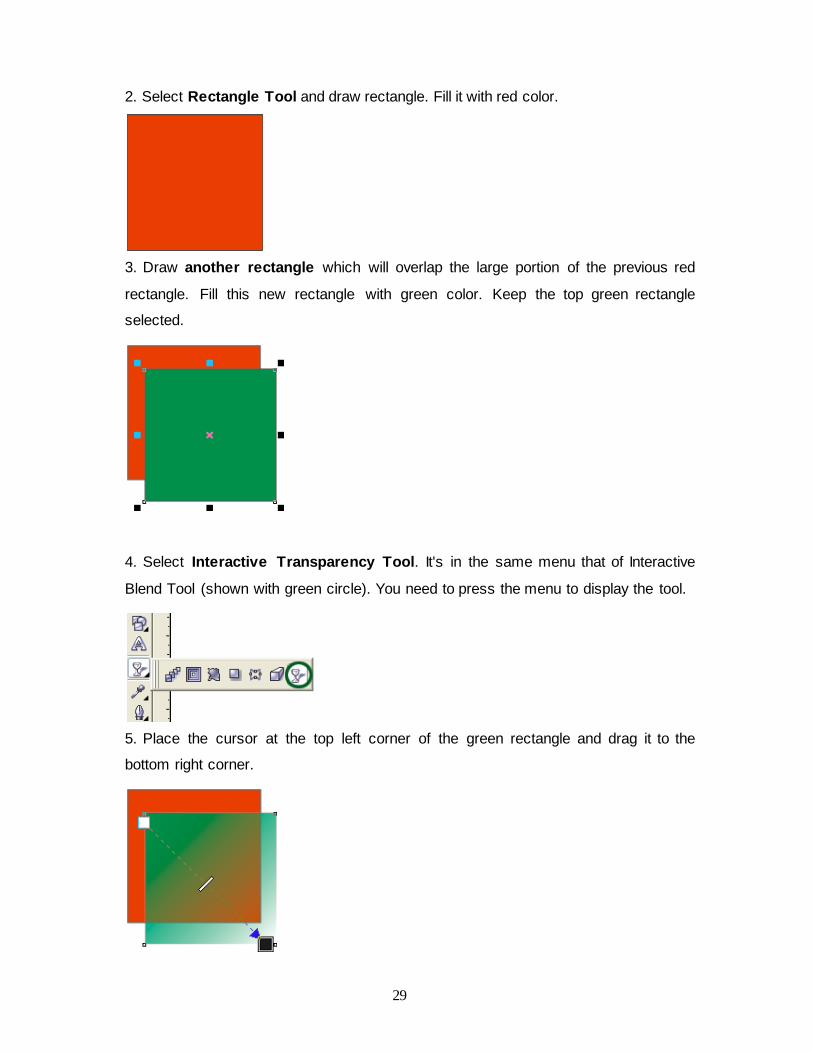
2. Select Rectangle Tool and draw rectangle. Fill it with red color.
3. Draw another rectangle which will overlap the large portion of the previous red
rectangle. Fill this new rectangle with green color. Keep the top green rectangle
selected.
4. Select Interactive Transparency Tool. It's in the same menu that of Interactive
Blend Tool (shown with green circle). You need to press the menu to display the tool.
5. Place the cursor at the top left corner of the green rectangle and drag it to the
bottom right corner.
30
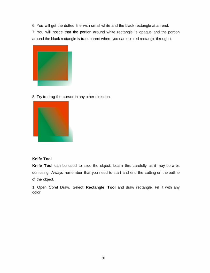
6. You will get the dotted line with small white and the black rectangle at an end.
7. You will notice that the portion around white rectangle is opaque and the portion
around the black rectangle is transparent where you can see red rectangle through it.
8. Try to drag the cursor in any other direction.
Knife Tool
Knife Tool can be used to slice the object. Learn this carefully as it may be a bit
confusing. Always remember that you need to start and end the cutting on the outline
of the object.
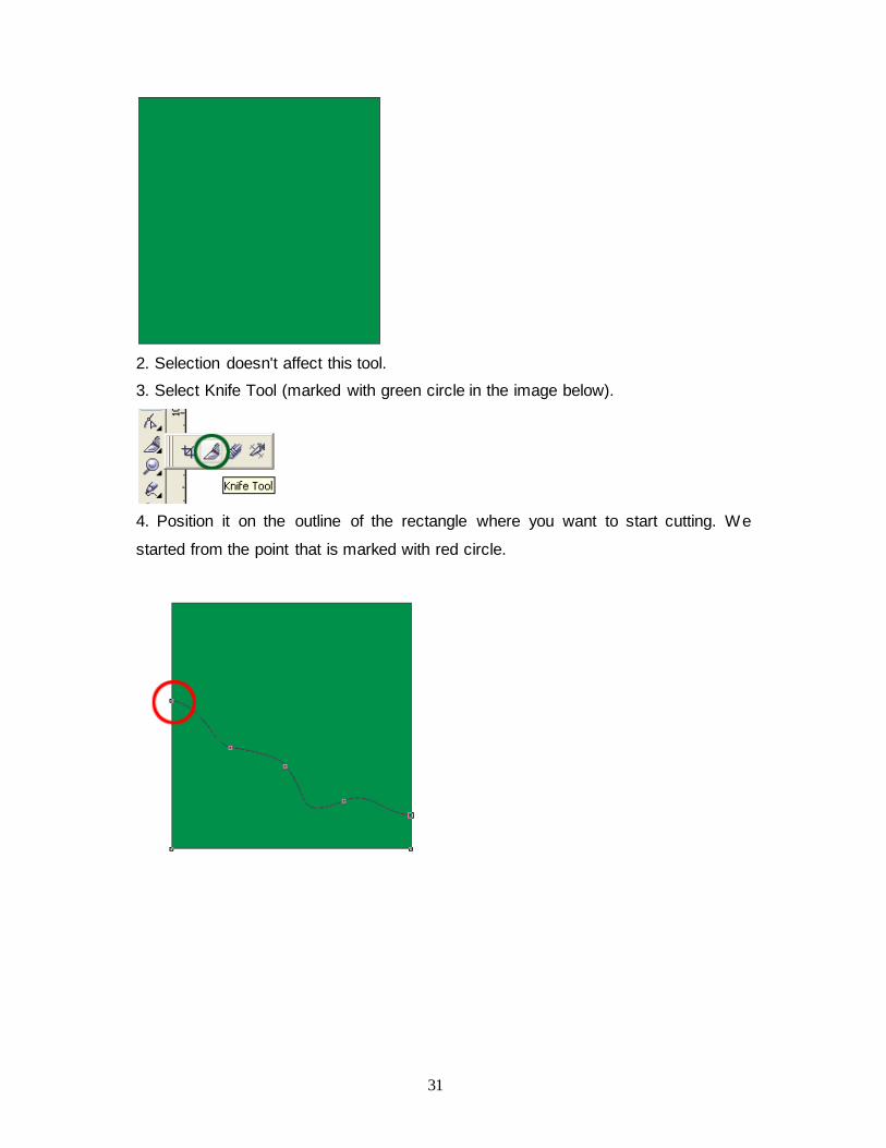
1. Open Corel Draw. Select Rectangle Tool and draw rectangle. Fill it with any
color.
31
2. Selection doesn't affect this tool.
3. Select Knife Tool (marked with green circle in the image below).
4. Position it on the outline of the rectangle where you want to start cutting. We
started from the point that is marked with red circle.
32
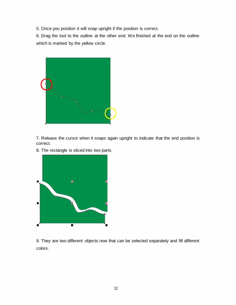
5. Once you position it will snap upright if the position is correct.
6. Drag the tool to the outline at the other end. We finished at the end on the outline
which is marked by the yellow circle.
7. Release the cursor when it snaps again upright to indicate that the end position is
correct.
8. The rectangle is sliced into two parts.
9. They are two different objects now that can be selected separately and fill different
colors.
33
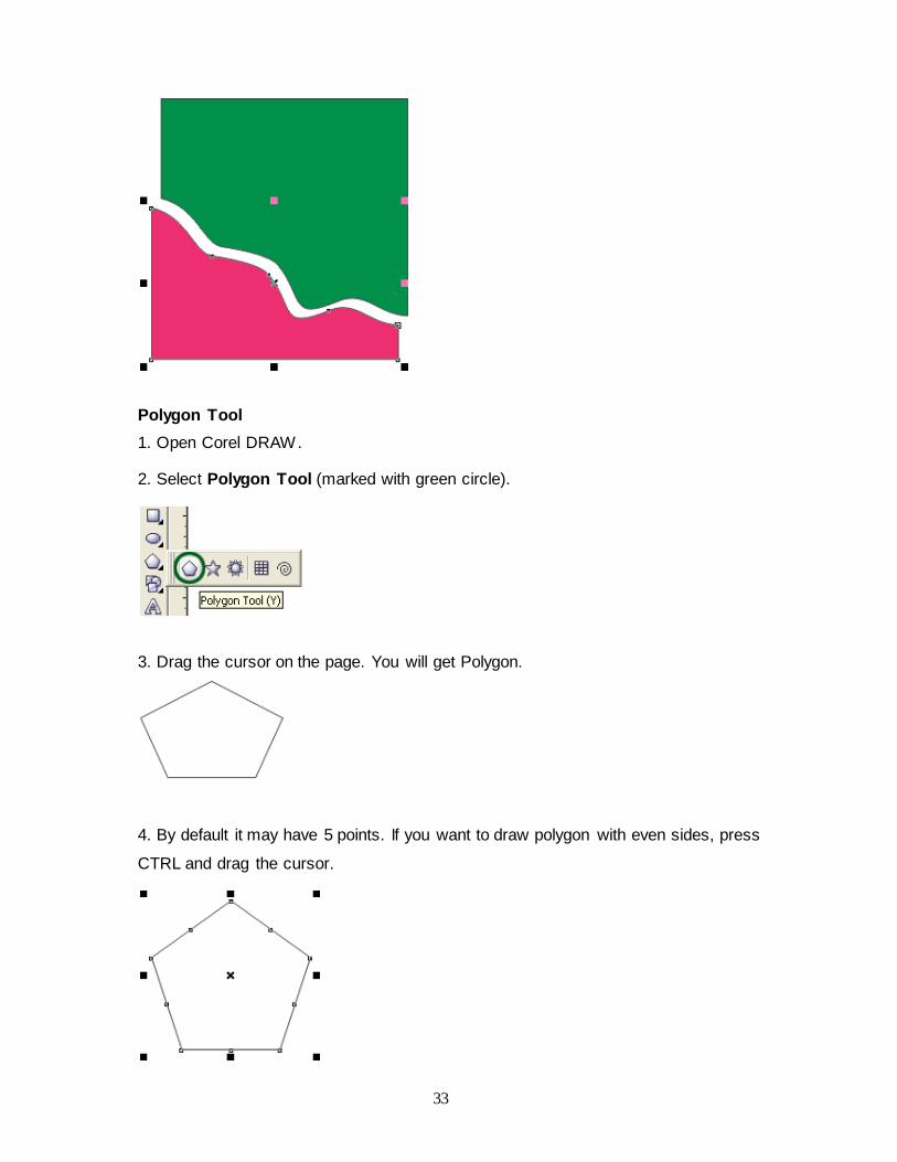
Polygon Tool
1. Open Corel DRAW.
2. Select Polygon Tool (marked with green circle).
3. Drag the cursor on the page. You will get Polygon.
4. By default it may have 5 points. If you want to draw polygon with even sides, press
CTRL and drag the cursor.

34
5. Please keep the polygon selected. Change the points of polygon in the property
bar to 7.
6. The 5-point polygon is changed to 7 points. It means it has 7 sides now.
7. Experiment with polygon by increasing and decreasing the points. Fill the color
and check out the effect.
35
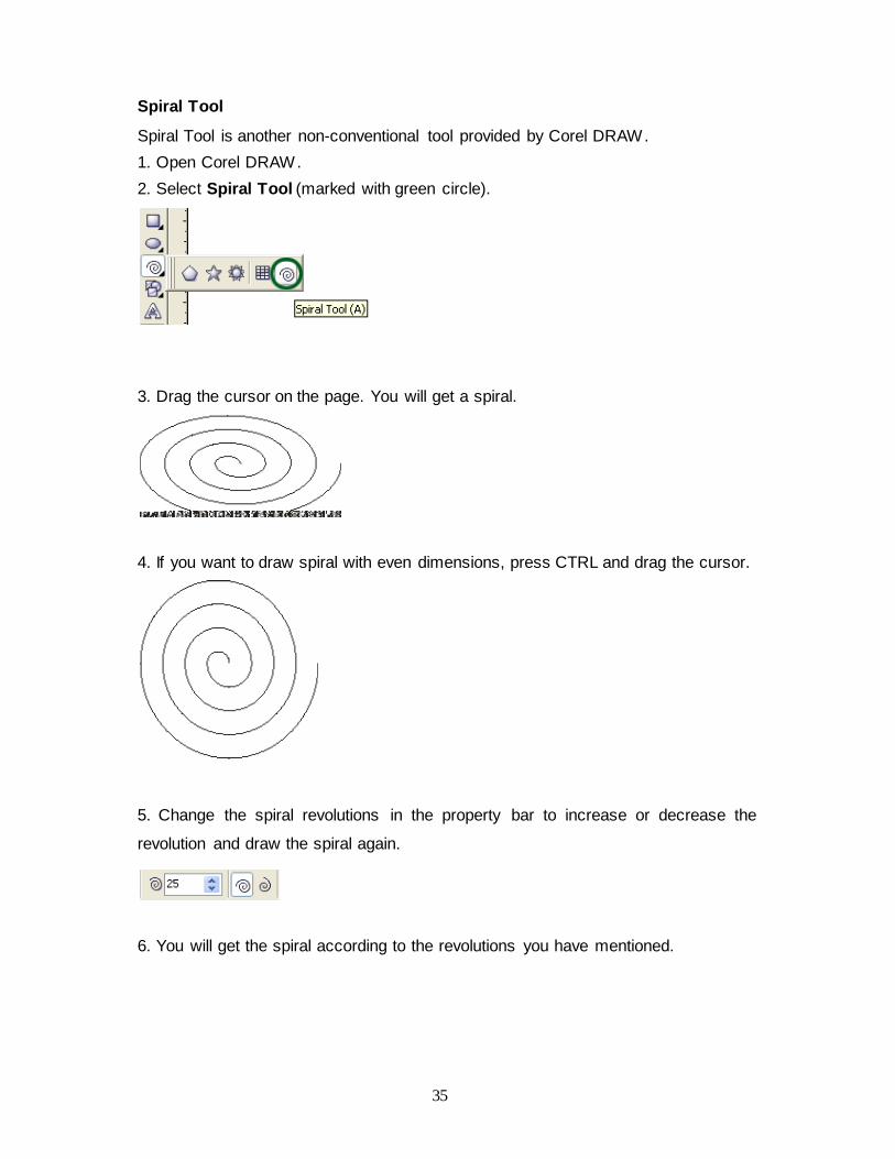
Spiral Tool
Spiral Tool is another non-conventional tool provided by Corel DRAW.
1. Open Corel DRAW.
2. Select Spiral Tool (marked with green circle).
3. Drag the cursor on the page. You will get a spiral.
4. If you want to draw spiral with even dimensions, press CTRL and drag the cursor.
5. Change the spiral revolutions in the property bar to increase or decrease the
revolution and draw the spiral again.
6. You will get the spiral according to the revolutions you have mentioned.
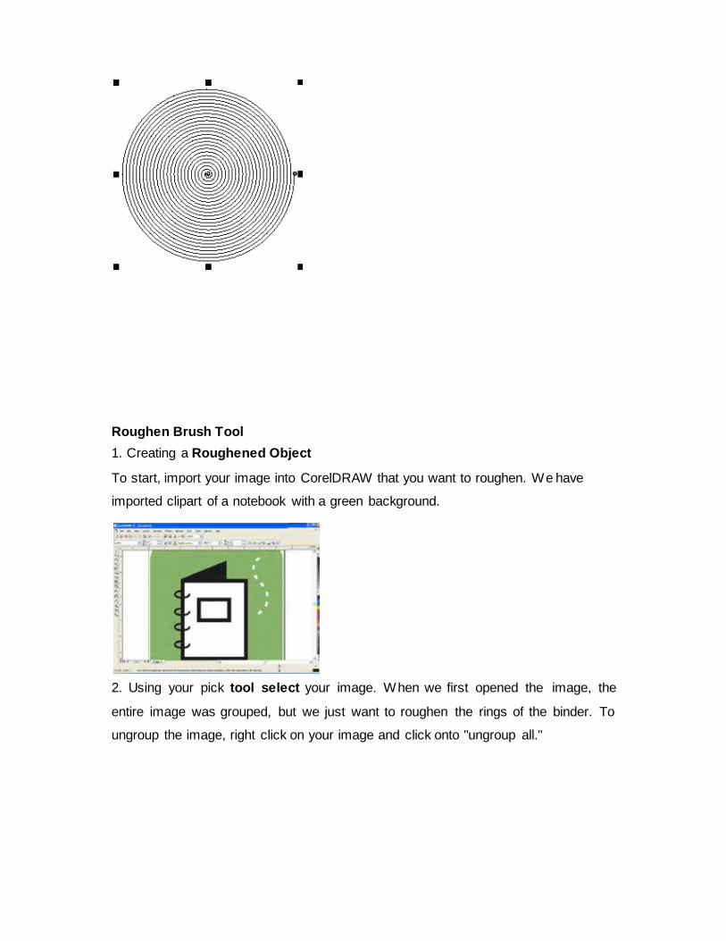
Roughen Brush Tool
1. Creating a Roughened Object
To start, import your image into CorelDRAW that you want to roughen. We have
imported clipart of a notebook with a green background.
2. Using your pick tool select your image. When we first opened the
image, the
entire image was grouped, but we just want to roughen the rings of the binder. To
ungroup the image, right click on your image and click onto "ungroup all."
37
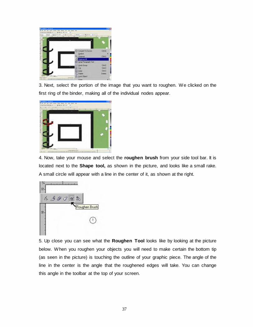
3. Next, select the portion of the image that you want to roughen. We clicked on the
first ring of the binder, making all of the individual nodes appear.
4. Now, take your mouse and select the roughen brush from your side tool bar. It is
located next to the Shape tool, as shown in the picture, and looks like a small rake.
A small circle will appear with a line in the center of it, as shown at the right.
5. Up close you can see what the Roughen Tool looks like by looking at the picture
below. When you roughen your objects you will need to make certain the bottom tip
(as seen in the picture) is touching the outline of your graphic piece. The angle of the
line in the center is the angle that the roughened edges will take. You can change
this angle in the toolbar at the top of your screen.
38
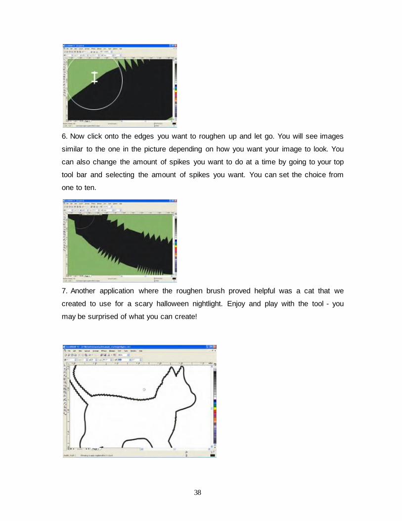
6. Now click onto the edges you want to roughen up and let go. You will see images
similar to the one in the picture depending on how you want your image to look. You
can also change the amount of spikes you want to do at a time by going to your top
tool bar and selecting the amount of spikes you want. You can set the choice from
one to ten.
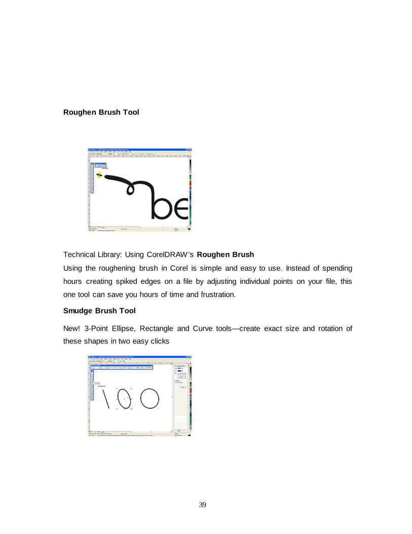
7. Another application where the roughen brush proved helpful was a cat that we
created to use for a scary halloween nightlight. Enjoy and play with the tool - you
may be surprised of what you can create!
39
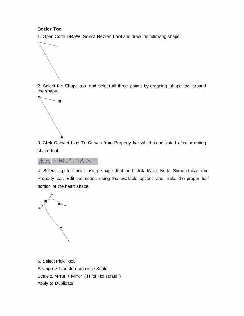
Roughen Brush Tool
Technical Library: Using CorelDRAW's Roughen Brush
Using the roughening brush in Corel is simple and easy to use. Instead of spending
hours creating spiked edges on a file by adjusting individual points on your file, this
one tool can save you hours of time and frustration.
Smudge Brush Tool
New! 3-Point Ellipse, Rectangle and Curve tools—create exact size and rotation of
these shapes in two easy clicks
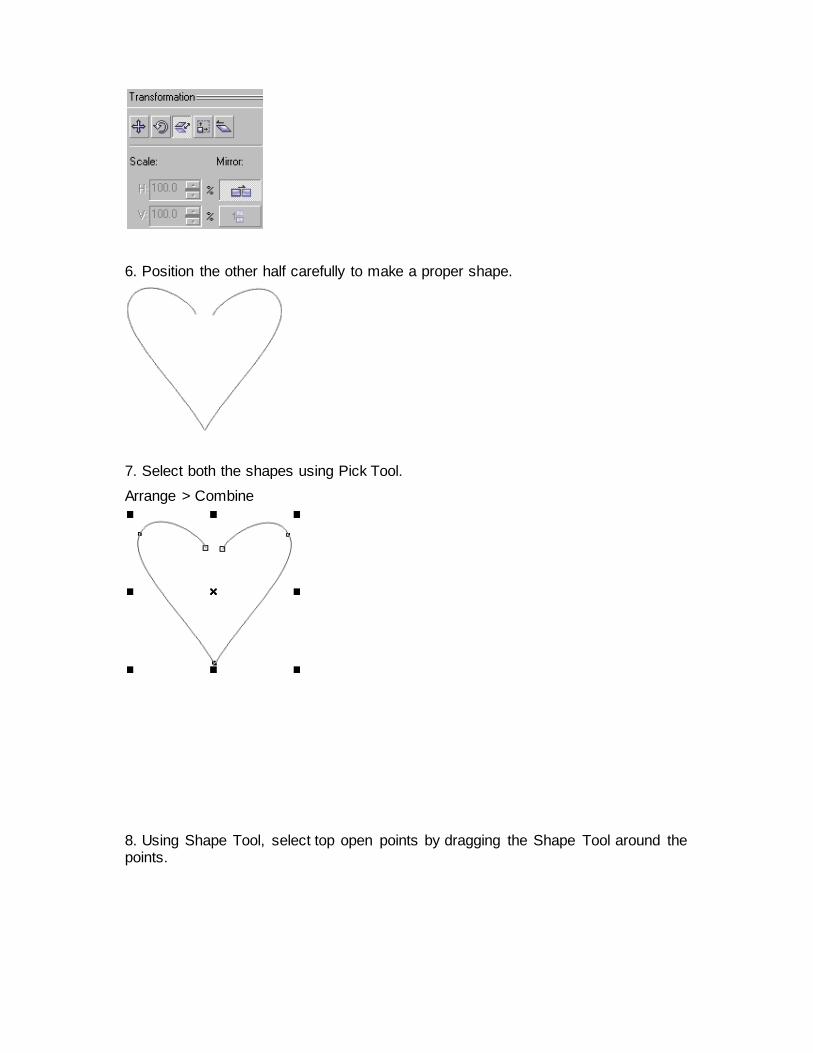
Bezier Tool
1. Open Corel DRAW. Select Bezier Tool and draw the following shape.
2. Select the Shape tool and select all three points by dragging shape tool around the shape.
3. Click Convert Line To Curves from Property bar which is activated after selecting
shape tool.
4. Select top left point using shape tool and click Make Node Symmetrical from
Property bar. Edit the nodes using the available options and make the proper half
portion of the heart shape.
5. Select Pick Tool.
Arrange > Transformations > Scale
Scale & Mirror > Mirror ( H for Horizontal )
Apply to Duplicate.
6. Position the other half carefully to make a proper shape.
7. Select both the shapes using Pick Tool.
Arrange > Combine
8. Using Shape Tool, select top open points by dragging the Shape Tool around the points.

9. Click Join Two Nodes from Property bar.
42
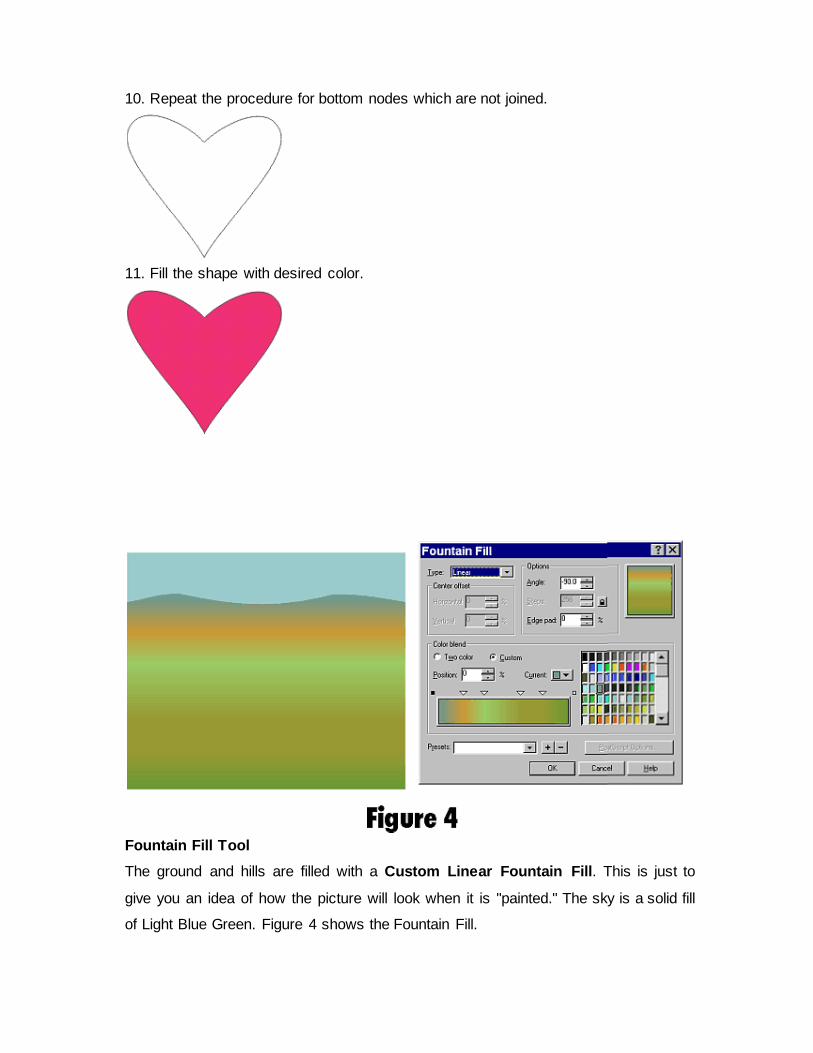
10. Repeat the procedure for bottom nodes which are not joined.
11. Fill the shape with desired color.
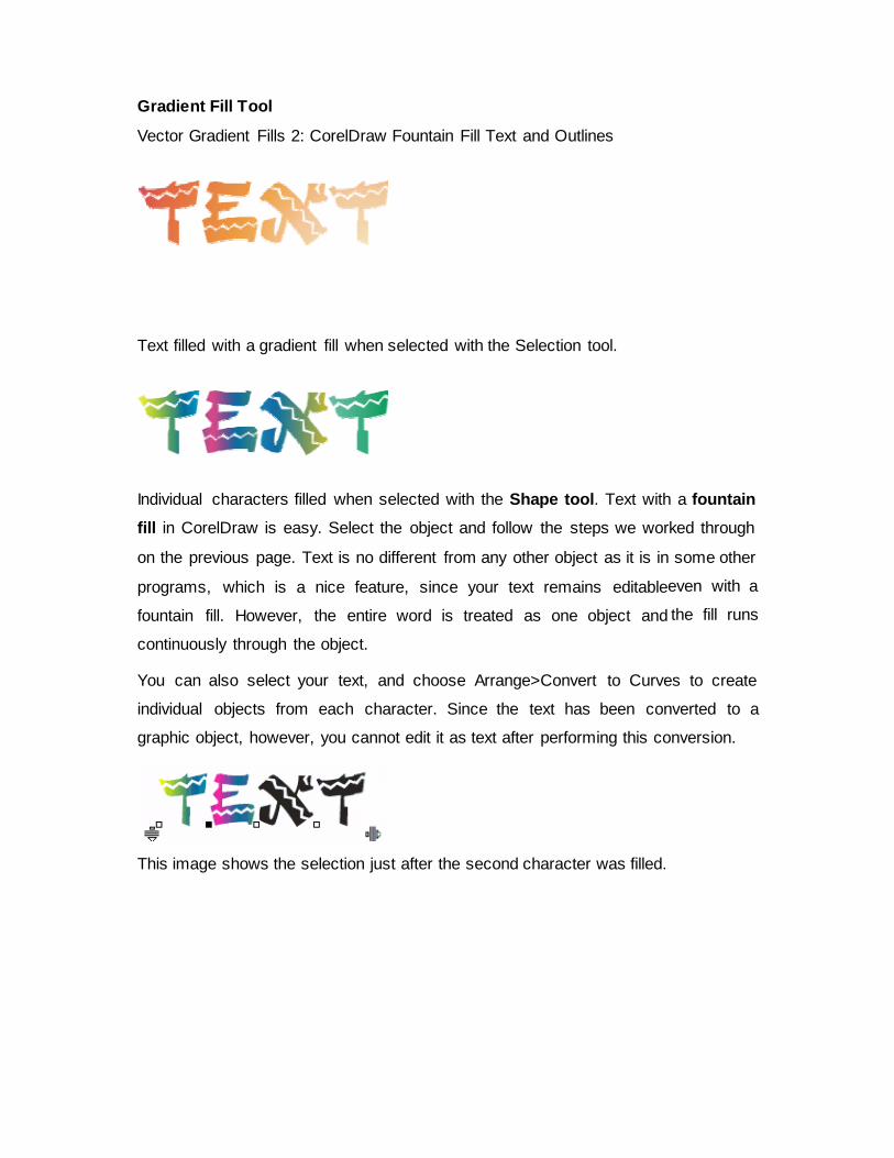
Fountain Fill Tool
The ground and hills are filled with a Custom Linear Fountain Fill. This is just to
give you an idea of how the picture will look when it is "painted." The sky is a solid fill
of Light Blue Green. Figure 4 shows the Fountain Fill.
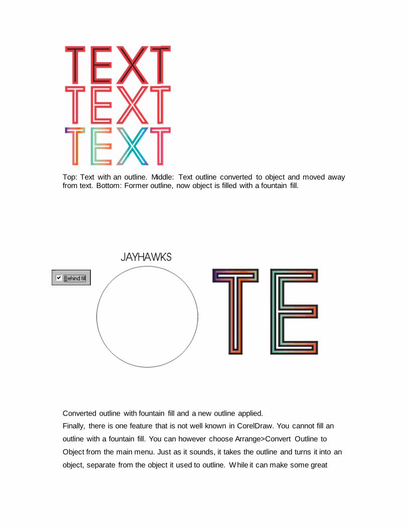
Gradient Fill Tool
Vector Gradient Fills 2: CorelDraw Fountain Fill Text and Outlines
Text filled with a gradient fill when selected with the Selection tool.
Individual characters filled when selected with the Shape tool. Text with a fountain
fill in CorelDraw is easy. Select the object and follow the steps we worked through
on the previous page. Text is no different from any other object as it is in some other
programs, which is a nice feature, since your text remains editable
fountain fill. However, the entire word is treated as one object and
continuously through the object.
even with a
the fill runs
You can also select your text, and choose Arrange>Convert to Curves to create
individual objects from each
character. Since the text has been converted to a
graphic object, however, you cannot edit it as text after performing this conversion.
This image shows the selection just after the second character was filled.
Top: Text with an outline. Middle: Text outline converted to object and moved away from text. Bottom: Former outline, now object is filled with a fountain fill.
Converted outline with fountain fill and a new outline applied.
Finally, there is one feature that is not well known in CorelDraw. You cannot fill an
outline with a fountain fill. You can however choose Arrange>Convert Outline to
Object from the main menu. Just as it sounds, it takes the outline and turns it into an
object, separate from the object it used to outline. While it can make some great

46
effects on objects, it is really powerful when you take one extra step and use it on
text.
Create your text. Apply a fairly thick outline – I have used a 20px outline for 140pt
text for the example shown here. (The original text was 140pts but I made it smaller
on export to fit.) Increase your letter spacing if necessary, since the outline tends to
join letters together. (See Text as Design for text manipulation techniques).
Choose Arrange>Convert Outline to Object. The outline becomes a separate object.
The sample at the left shows the text with regular outline first, with the outline moved
away from the text in the second sample. Fill with the fountain fill you desire ... neat
effect. If you really want to push the technique, start with your characters spread
further apart, and apply an outline to the original outline. You may find the result is
better when you specify a wide outline. Then open the Outline Pen window through
the Outline Pen tool, and check Behind Fill, located at the bottom left of the window.
This sends the outline behind the object and can be easier to control the effect.
At the left, I have included a magnified version of the outline on an outline effect. Of
course, you could also have the original text behind filled with another color. It is
when you see effects like this, and how easy and accurate the methods are, that you
begin to realize why designers insist on having both raster and vector programs at
their disposal.
Now, lets take a look at creating blends for even more color blending power.
47
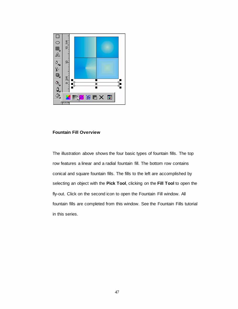
Fountain Fill Overview
The illustration above shows the four basic types of fountain fills. The top
row features a linear and a radial fountain fill. The bottom row contains
conical and square fountain fills. The fills to the left are accomplished by
selecting an object with the Pick Tool, clicking on the Fill Tool to open the
fly-out. Click on the second icon to open the Fountain Fill window. All
fountain fills are completed from this window. See the Fountain Fills tutorial
in this series.
48
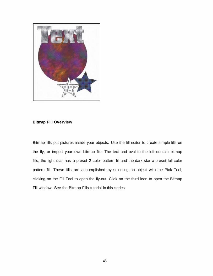
Bitmap Fill Overview
Bitmap fills put pictures inside your objects. Use the fill editor to create simple fills on
the fly, or import your own bitmap file. The text and oval to the left contain bitmap
fills, the light star has a preset 2 color pattern fill and the dark star a preset full color
pattern fill. These fills are accomplished by selecting an object with the Pick Tool,
clicking on the Fill Tool to open the fly-out. Click on the third icon to open the Bitmap
Fill window. See the Bitmap Fills tutorial in this series.
49
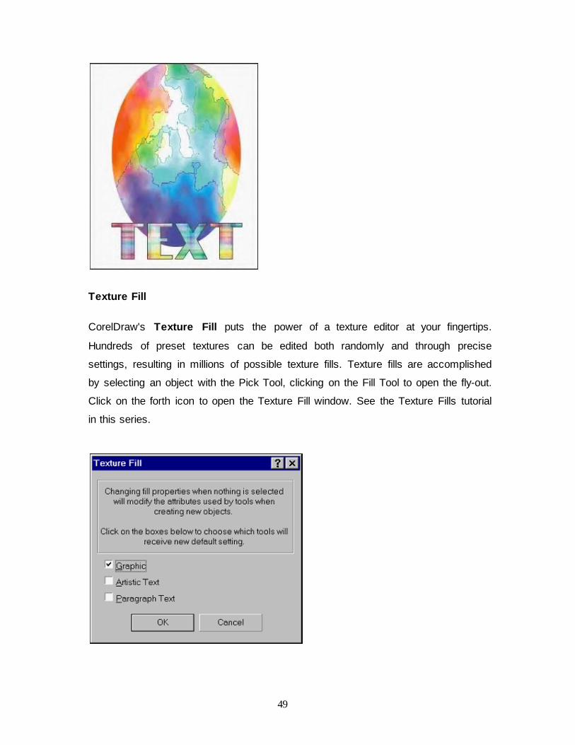
Texture Fill
CorelDraw's Texture Fill puts the power of a texture editor at your fingertips.
Hundreds of preset textures can be edited both randomly and through precise
settings, resulting in millions of possible texture fills. Texture fills are accomplished
by selecting an object with the Pick Tool, clicking on the Fill Tool to open the fly-out.
Click on the forth icon to open the Texture Fill window. See the Texture Fills tutorial
in this series.

Set Default Fill
When you create any object, a default fill is applied. The CorelDraw default is "no fill"
but you can set any fill as the default fill. Make sure nothing is selected in your
document, or set defaults before you create any objects. Select the
fill you want
through any method. A pop-up screen will ask you which objects you would like this
fill to affect. Choose to have the fill apply to all graphics, artistic or paragraph text.
Click OK and the fill you choose will become the default.
Remove Fill
Select object with the Pick Tool. Click on the "No Color" well in the color palette.
Or, click on the Fill Tool in the Toolbox and chose the X icon.
The Fill tool presents the flyout containing the Fountain Fill tool.
51
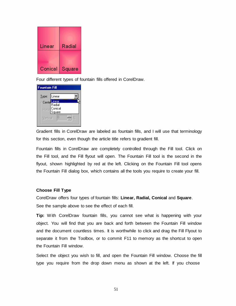
Four different types of fountain fills offered in CorelDraw.
Gradient fills in CorelDraw are labeled as fountain fills, and I will use that terminology
for this section, even though the article title refers to gradient fill.
Fountain fills in CorelDraw are completely controlled through the Fill tool. Click on
the Fill tool, and the Fill flyout will open. The Fountain Fill tool is the second in the
flyout, shown highlighted by red at the left. Clicking on the Fountain Fill tool opens
the Fountain Fill dialog box, which contains all the tools you require to create your fill.
Choose Fill Type
CorelDraw offers four types of fountain fills: Linear, Radial, Conical and Square.
See the sample above to see the effect of each fill.
Tip: With CorelDraw fountain fills, you cannot see what is happening with your
object. You will find that you are back and forth between the Fountain Fill window
and the document countless times. It is worthwhile to click and drag the Fill Flyout to
separate it from the Toolbox, or to commit F11 to memory as the shortcut to open
the Fountain Fill window.
Select the object you wish to fill, and open the Fountain Fill window. Choose the fill
type you require from the drop down menu as shown at the left. If you choose
52
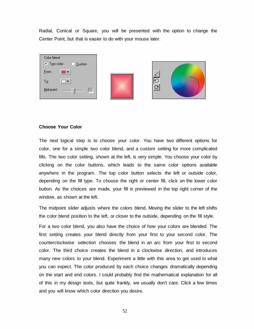
Radial, Conical or Square, you will be presented with the option to change the
Center Point, but that is easier to do with your mouse later.
Choose Your Color
The next logical step is to choose your color. You have two different options for
color, one for a simple two color blend, and a custom setting for more complicated
fills. The two color setting, shown at the left, is very simple. You choose your color by
clicking on the color buttons, which leads to the same color options available
anywhere in the program. The top color button selects the left or outside color,
depending on the fill type. To choose the right or center fill, click on the lower color
button. As the choices are made, your fill is previewed in the top right corner of the
window, as shown at the left.
The midpoint slider adjusts where the colors blend. Moving the slider to the left shifts
the color blend position to the left, or closer to the outside, depending on the fill style.
For a two color blend, you also have the choice of how your colors are blended. The
first setting creates your blend directly from your first to your second color. The
counterclockwise selection chooses the blend in an arc from your first to second
color. The third choice creates the blend in a clockwise direction, and introduces
many new colors to your blend. Experiment a little with this area to get used to what
you can expect. The color produced by each choice changes dramatically depending
on the start and end colors. I could probably find the mathematical explanation for all
of this in my design texts, but quite frankly, we usually don't care. Click a few times
and you will know which color direction you desire.
53
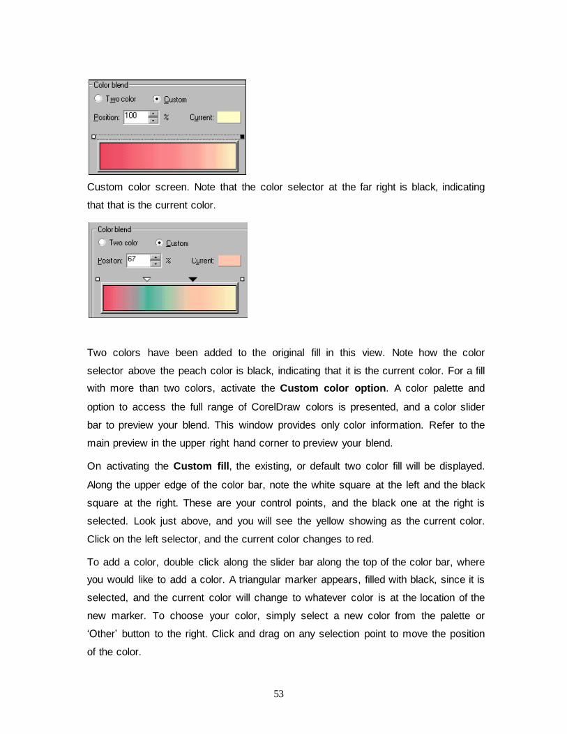
Custom color screen. Note that the color selector at the far right is black, indicating
that that is the current color.
Two colors have been added to the original fill in this view. Note how the color
selector above the peach color is black, indicating that it is the current color. For a fill
with more than two colors, activate the Custom color option. A color palette and
option to access the full range of CorelDraw colors is presented, and a color slider
bar to preview your blend. This window provides only color information. Refer to the
main preview in the upper right hand corner to preview your blend.
On activating the Custom fill, the existing, or default two color fill will be displayed.
Along the upper edge of the color bar, note the white square at the left and the black
square at the right. These are your control points, and the black one at the right is
selected. Look just above, and you will see the yellow showing as the current color.
Click on the left selector, and the current color changes to red.
To add a color, double click along the slider bar along the top of the color bar, where
you would like to add a color. A triangular marker appears, filled with black, since it is
selected, and the current color will change to whatever color is at the location of the
new marker. To choose your color, simply select a new color from the palette or
‘Other’ button to the right. Click and drag on any selection point to move the position
of the color.
54
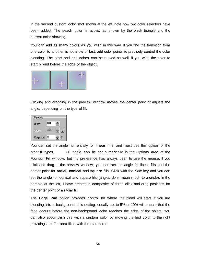
In the second custom color shot shown at the left, note how two color selectors have
been added. The peach color is active, as shown by the black triangle and the
current color showing.
You can add as many colors as you wish in this way. If you find the transition from
one color to another is too slow or fast, add color points to precisely control the color
blending. The start and end colors can be moved as well, if you wish the color to
start or end before the edge of the object.
Clicking and dragging in the preview window moves the center point or adjusts the
angle, depending on the type of fill.
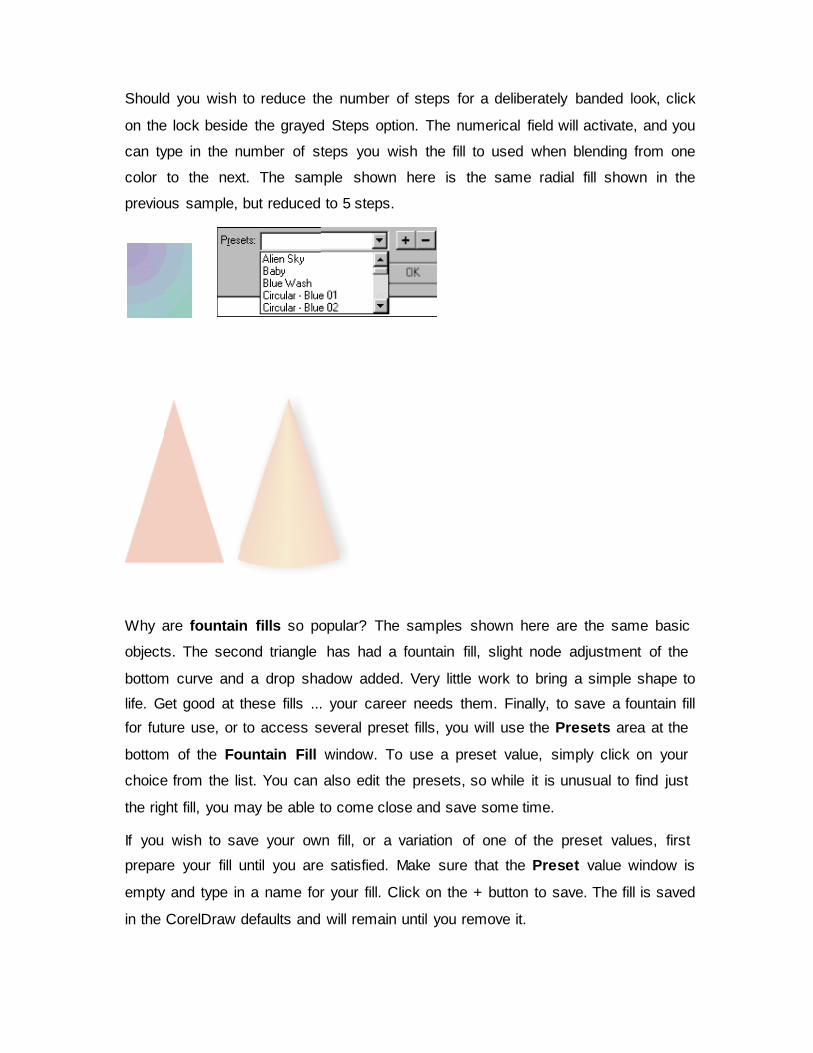
You can set the angle numerically for linear fills, and must use this option for the
other fill types. Fill angle can be set numerically in the Options area of the
Fountain Fill window, but my preference has always been to use the mouse. If you
click and drag in the preview window, you can set the angle for linear fills and the
center point for radial, conical and square fills. Click with the Shift key and you can
set the angle for conical and square fills (angles don't mean much to a circle). In the
sample at the left, I have created a composite of three click and drag positions for
the center point of a radial fill.
The Edge Pad option provides control for where the blend will start. If you are
blending into a background, this setting, usually set to 5% or 10% will ensure that the
fade occurs before the non-background color reaches the edge of the object. You
can also accomplish this with a custom color by moving the first color to the right
providing a buffer area filled with the start color.
Should you wish to reduce the number of steps for a deliberately banded look, click
on the lock beside the grayed Steps option. The numerical field will activate, and you
can type in the number of steps you wish the fill to used when blending from one
color to the next. The sample shown here is the same radial fill shown in the
previous sample, but reduced to 5 steps.
Why are fountain fills so popular? The samples shown here are the same basic
objects. The second triangle
has had a fountain fill, slight node adjustment of the
bottom curve and a drop shadow added. Very little work to bring a simple shape to
life. Get good at these fills ... your career needs them. Finally, to save a fountain fill
for future use, or to access several preset fills, you will use the Presets area at the
bottom of the Fountain Fill
window. To use a preset value, simply click on your
choice from the list. You can also edit the presets, so while it is unusual to find just
the right fill, you may be able to come close and save some time.
If you wish to save your own fill, or a variation of one of the preset values, first
prepare your fill until you are satisfied. Make sure that the Preset value window is
empty and type in a name for your fill. Click on the + button to save. The fill is saved
in the CorelDraw defaults and will remain until you remove it.
56
You can also save a fill that you created earlier, as long as you still have the
document containing the fill in CDR format. Select the object with the fill you wish to
save and open the Fountain Fill window. The fill will be featured. Follow the steps
above to save.
To remove a fill from the list, highlight it and select the button.
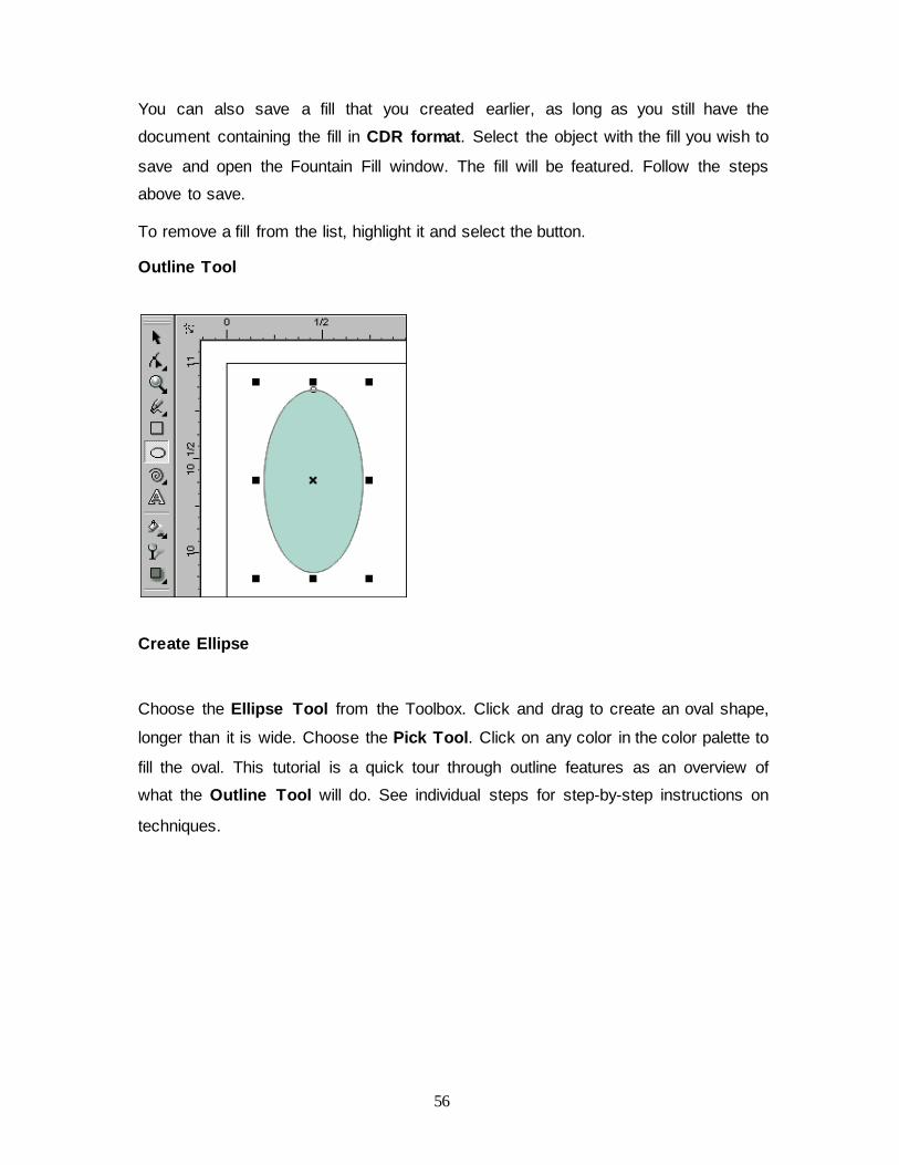
Outline Tool
Create Ellipse
Choose the Ellipse Tool from the Toolbox. Click and drag to create an oval shape,
longer than it is wide. Choose the Pick Tool. Click on any color in the color palette to
fill the oval. This tutorial is a quick tour through outline features as an overview of
what the Outline Tool will do. See individual steps for step-by-step instructions on
techniques.
57
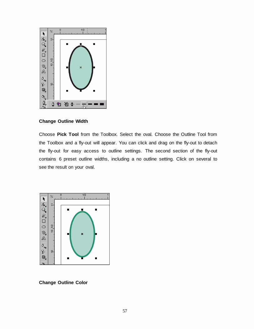
Change Outline Width
Choose Pick Tool from the Toolbox. Select the oval. Choose the Outline Tool from
the Toolbox and a fly-out will appear. You can click and drag on the fly-out to detach
the fly-out for easy access to outline settings. The second section of the fly-out
contains 6 preset outline widths, including a no outline setting. Click on several to
see the result on your oval.
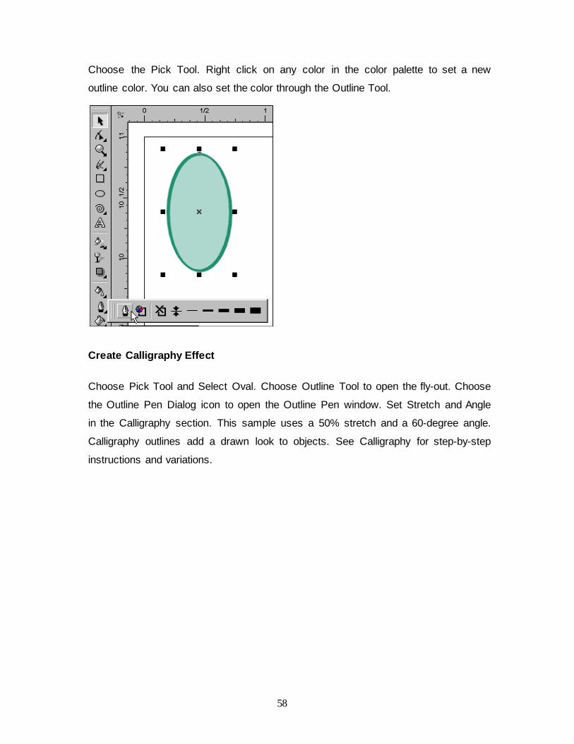
Change Outline Color
58
Choose the Pick Tool. Right click on any color in the color palette to set a new
outline color. You can also set the color through the Outline Tool.
Create Calligraphy Effect
Choose Pick Tool and Select Oval. Choose Outline Tool to open the fly-out. Choose
the Outline Pen Dialog icon to open the Outline Pen window. Set Stretch and Angle
in the Calligraphy section. This sample uses a 50% stretch and a 60-degree angle.
Calligraphy outlines add a drawn look to objects. See Calligraphy for step-by-step
instructions and variations.
59
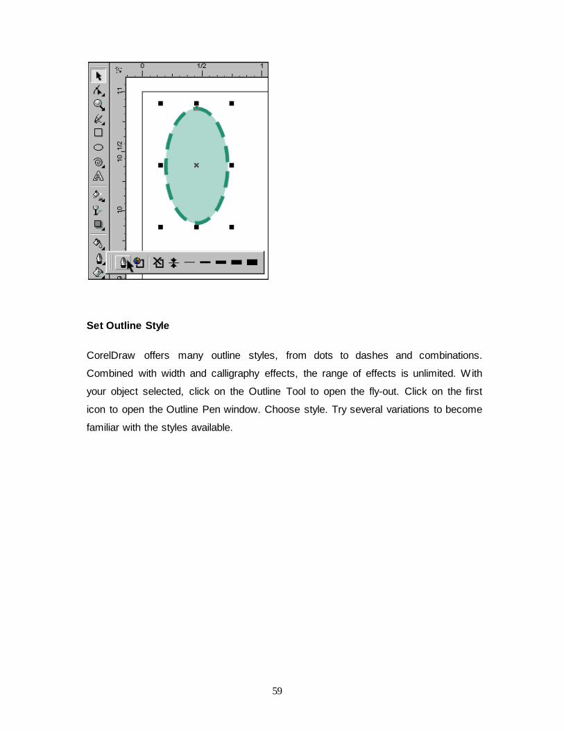
Set Outline Style
CorelDraw offers many outline styles, from dots to dashes and combinations.
Combined with width and calligraphy effects, the range of effects is unlimited. With
your object selected, click on the Outline Tool to open the fly-out. Click on the first
icon to open the Outline Pen window. Choose style. Try several variations to become
familiar with the styles available.
60
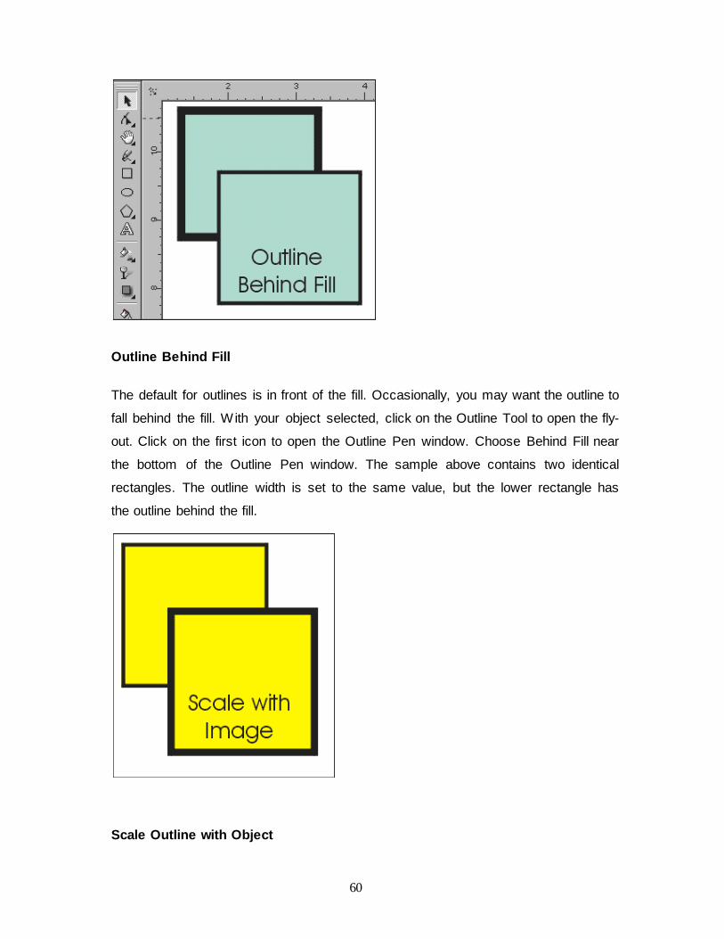
Outline Behind Fill
The default for outlines is in front of the fill. Occasionally, you may want the outline to
fall behind the fill. W ith your object selected, click on the Outline Tool to open the fly-
out. Click on the first icon to open the Outline Pen window. Choose Behind Fill near
the bottom of the Outline Pen window. The sample above contains two identical
rectangles. The outline width is set to the same value, but the lower rectangle has
the outline behind the fill.
Scale Outline with Object
61
Outlines are set numerically, and will remain the same width once set. But often, the
proportion between the outline and the fill should remain the same, even if the image
is reduced or enlarged. You can set your outline to remain proportional. Choose
Scale with Image near the bottom of the Outline Pen window. The sample above
contains two identical rectangles, drawn at a small size with a thick outline and
enlarged. The lower sample has been set.
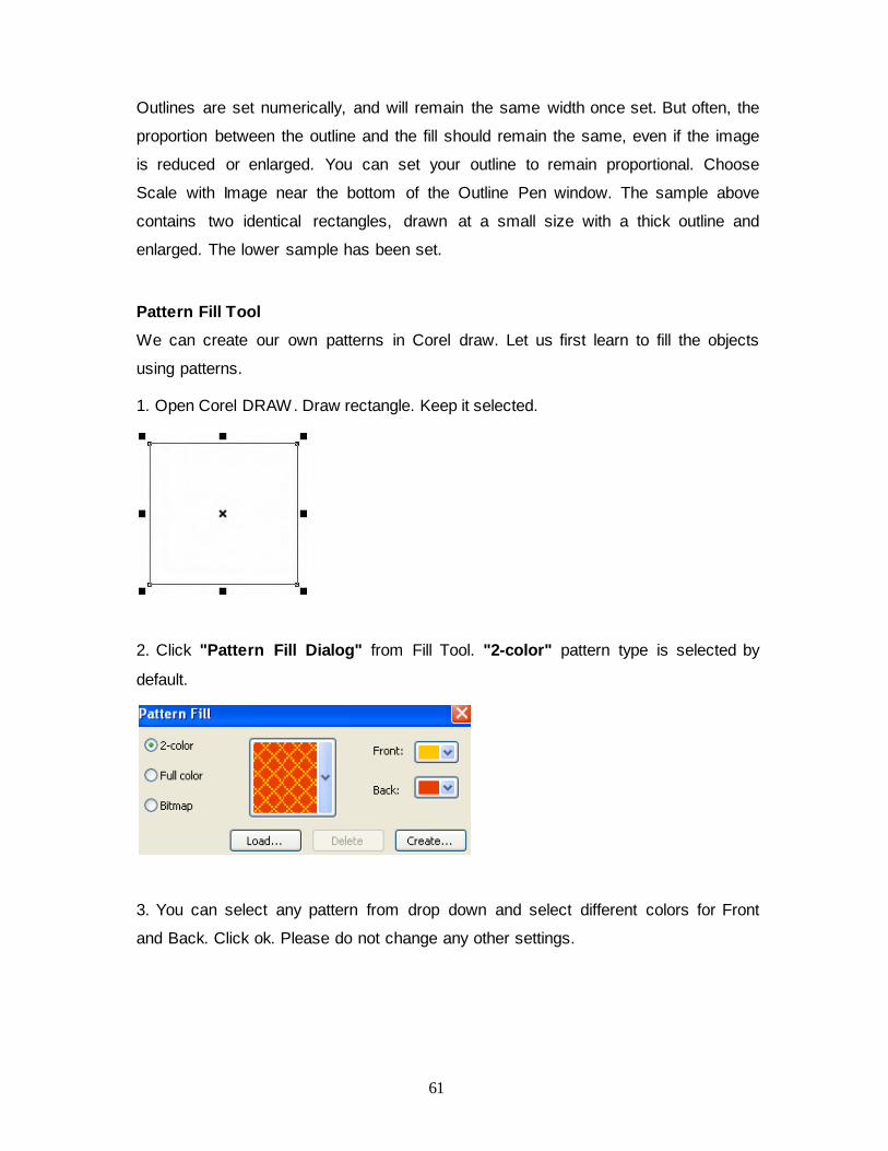
Pattern Fill Tool
We can create our own patterns in Corel draw. Let us first learn to fill the objects
using patterns.
1. Open Corel DRAW. Draw rectangle. Keep it selected.
2. Click "Pattern Fill Dialog" from Fill Tool. "2-color" pattern type is selected by
default.
3. You can select any pattern from drop down and select different colors for Front
and Back. Click ok. Please do not change any other settings.
62
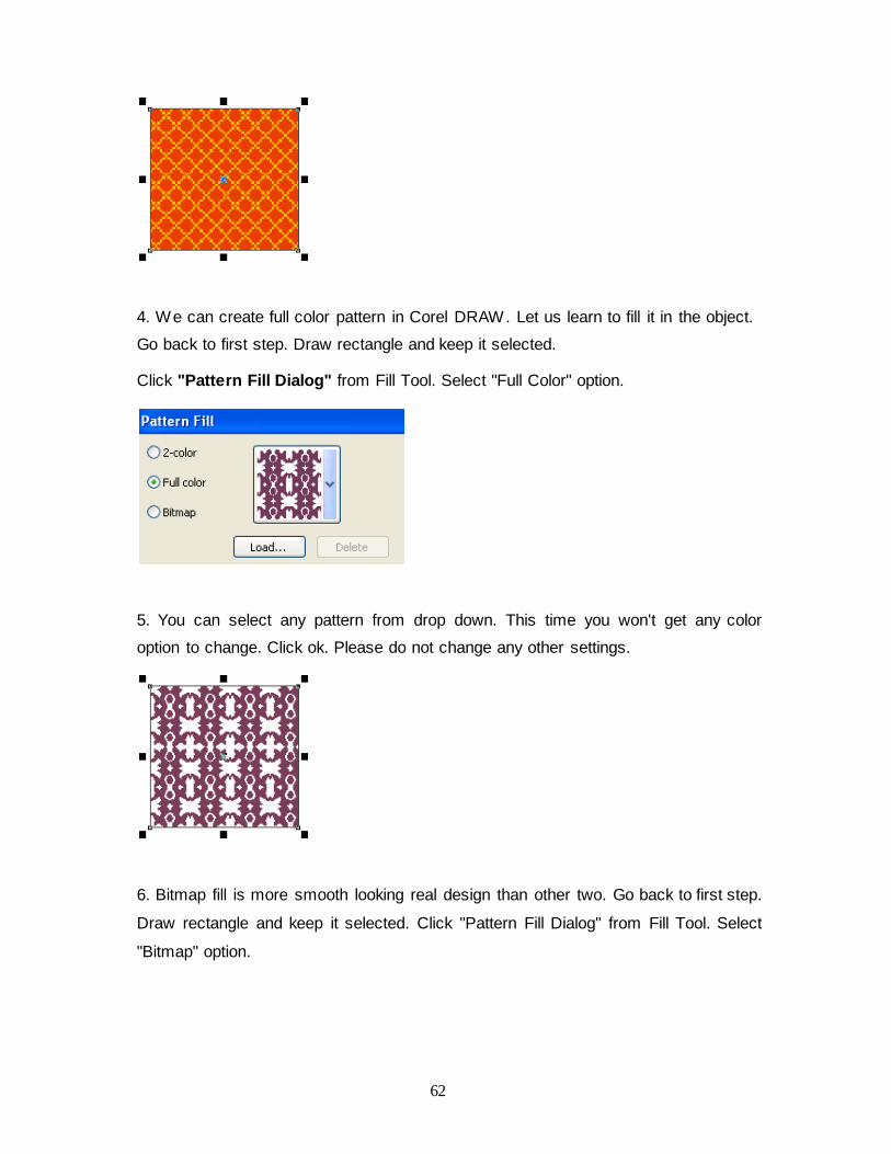
4. We can create full color pattern in Corel DRAW. Let us learn to fill it in the object.
Go back to first step. Draw rectangle and keep it selected.
Click "Pattern Fill Dialog" from Fill Tool. Select "Full Color" option.
5. You can select any pattern from drop down. This time you won't get any color
option to change. Click ok. Please do not change any other settings.
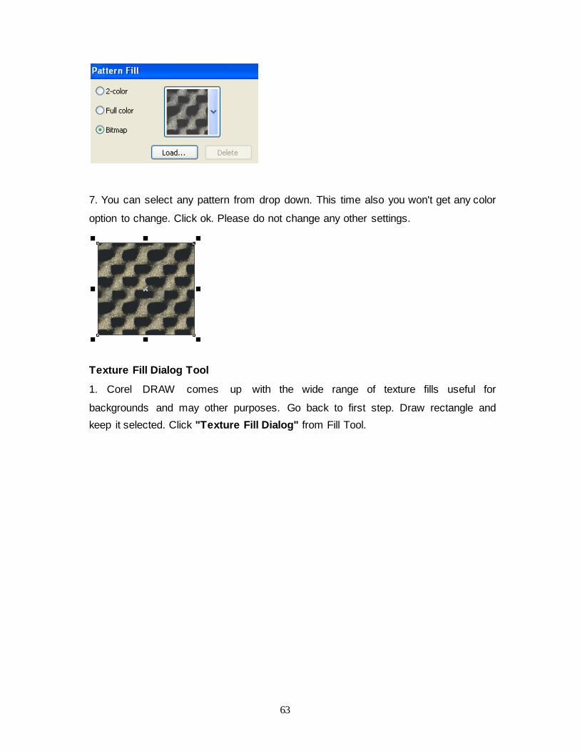
6. Bitmap fill is more smooth looking real design than other two. Go back to first step.
Draw rectangle and keep it selected. Click "Pattern Fill Dialog" from Fill Tool. Select
"Bitmap" option.
63
7. You can select any pattern from drop down. This time also you won't get any color
option to change. Click ok. Please do not change any other settings.
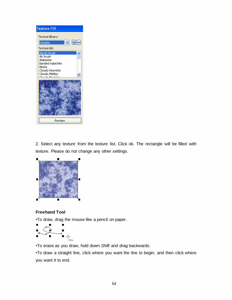
Texture Fill Dialog Tool
1. Corel DRAW comes up with the wide range of texture fills useful for
backgrounds and may other purposes. Go back to first step. Draw rectangle and
keep it selected. Click "Texture Fill Dialog" from Fill Tool.
64
2. Select any texture from the texture list. Click ok. The rectangle will be filled with
texture. Please do not change any other settings.
Freehand Tool
•To draw, drag the mouse like a pencil on paper.
•To erase as you draw, hold down Shift and drag backwards.
•To draw a straight line, click where you want the line to begin, and then click where
you want it to end.
•To set options, double-click the Freehand Tool.
•To change a line or curve’s shape, click the Shape tool .
Artistic Media Tool
•To draw with the Artistic Media Tool, click and drag along the path you want, like a
pencil on paper.
•To choose a drawing mode, click the appropriate button on the property bar:
o Preset mode button
o Brush mode button
— lets you draw preset curves
— lets you draw brush curves
o Object sprayer mode button — lets you spray objects
o Calligraphic mode button — lets you draw calligraphic curves
o Pressure-sensitive mode button — lets you draw pressure-sensitive curves
•To specify settings for the drawing mode you’ve chosen, use the controls on the
property bar.
•To vary the pen pressure when drawing pressure-sensitive curves, press the Up
arrow Down arrow.
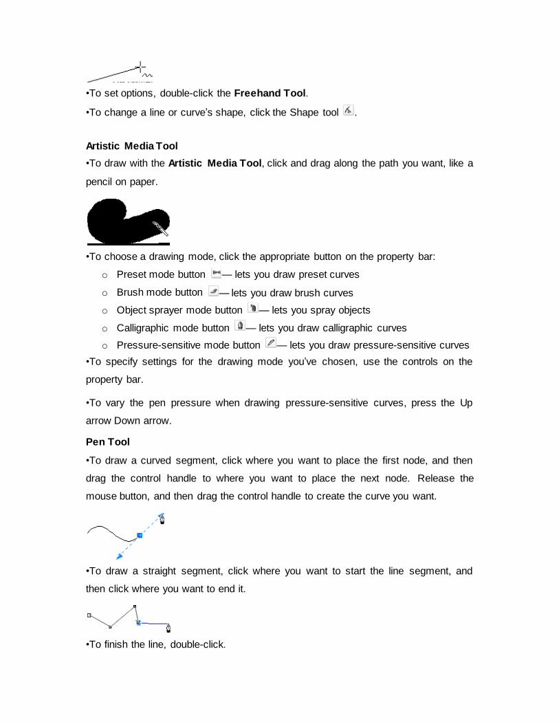
Pen Tool
•To draw a curved segment, click where you want to place the first node, and then
drag the control handle to where you want to place the next node.
Release the
mouse button, and then drag the control handle to create the curve you want.
•To draw a straight segment, click where you want to start the line segment, and
then click where you want to end it.
•To finish the line, double-click.
•To add a node, point to where you want to add the node, and then click.
•To delete a node, point to it, and then click.
Polyline Tool
•To draw a straight segment, click where you want to start the line segment, and
then click where you want to end it.
•To draw a curved segment, click where you want to start the segment, and then
drag across the drawing page.
•To end the line, double-click.
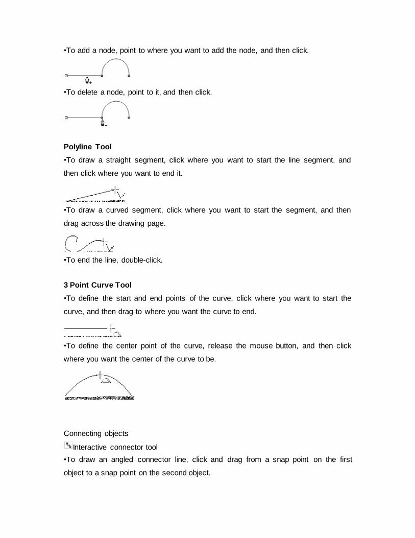
3 Point Curve Tool
•To define the start and end points of the curve, click where you want to start the
curve, and then drag to where you want the curve to end.
•To define the center point of the curve, release the mouse button, and then click
where you want the center of the curve to be.
Connecting objects
Interactive connector tool
•To draw an angled connector line, click and drag from a snap point
object to a snap point on the second object.
on the first
•To change an angled connector line to a straight connector line, click the Straight
connector button on the property bar.
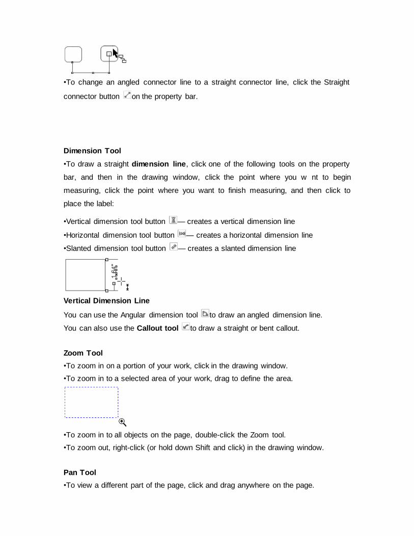
Dimension Tool
•To draw a straight dimension line, click one of the following tools on the property
bar, and then in the drawing window, click the point where you w
nt to begin
measuring, click the point where you want to finish measuring, and then click to
place the label:
•Vertical dimension tool button — creates a vertical dimension line
•Horizontal dimension tool button — creates a horizontal dimension line
•Slanted dimension tool button — creates a slanted dimension line
Vertical Dimension Line
You can use the Angular dimension tool to draw an angled dimension line.
You can also use the Callout tool to draw a straight or bent callout.
Zoom Tool
•To zoom in on a portion of your work, click in the drawing window.
•To zoom in to a selected area of your work, drag to define the area.
•To zoom in to all objects on the page, double-click the Zoom tool.
•To zoom out, right-click (or hold down Shift and click) in the drawing window.
Pan Tool
•To view a different part of the page, click and drag anywhere on the page.
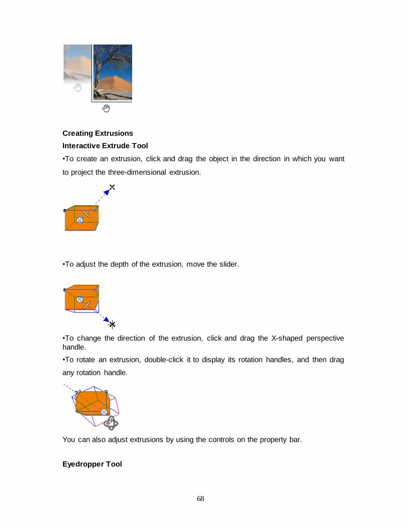
Creating Extrusions
Interactive Extrude Tool
•To create an extrusion, click and drag the object in the direction in which you want
to project the three-dimensional extrusion.
•To adjust the depth of the extrusion, move the slider.
•To change the direction of the extrusion, click and drag the X-shaped perspective
handle.
•To rotate an extrusion, double-click it to display its rotation handles, and then drag
any rotation handle.
You can also adjust extrusions by using the controls on the property bar.
Eyedropper Tool
68

•To copy fill and outline colors from an object, choose Object attributes from the list
box on the property bar, and then click the object.
•To copy a color from the screen, choose Sample color from the list box on the
property bar, click Select from Desktop if required, and then click the color.
•To paste fill and outline colors to an object, switch to the Paintbucket tool by
holding down Shift or clicking the Paintbucket tool.
Basic Shapes Tool
•To draw a basic shape, choose a shape from the Perfect Shapes picker on the
property bar, and then drag in the drawing window until the shape is the size you
want.
•To adjust the basic shape, drag its shadow.

See "Moving, scaling, and stretching objects" or "Rotating and skewing
objects" for information on transforming this object.
Drawing Arrow Shapes
Arrow Shapes Tool
•To draw an arrow shape, choose a shape from the Perfect Shapes picker on the
property bar, and then drag in the drawing window until the shape is the size you
want.
•To adjust the arrow shape, drag its shadow.
Drawing Flowchart Shapes
Flowchart Shapes Tool
•To draw a flowchart shape, choose a shape from the Perfect Shapes picker on the
property bar, and then drag in the drawing window until the shape is the size you
want.
Drawing Callout Shapes
Callout Shapes Tool
71
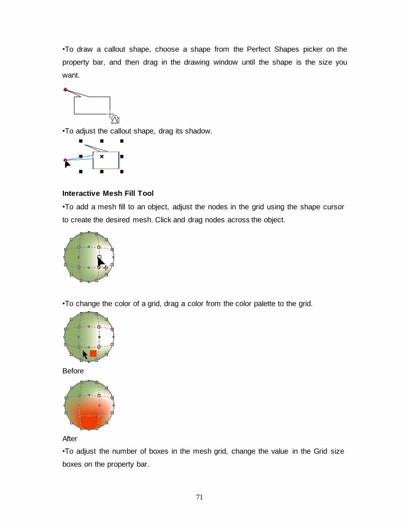
•To draw a callout shape, choose a shape from the Perfect Shapes picker on the
property bar, and then drag in the drawing window until the shape is the size you
want.
•To adjust the callout shape, drag its shadow.
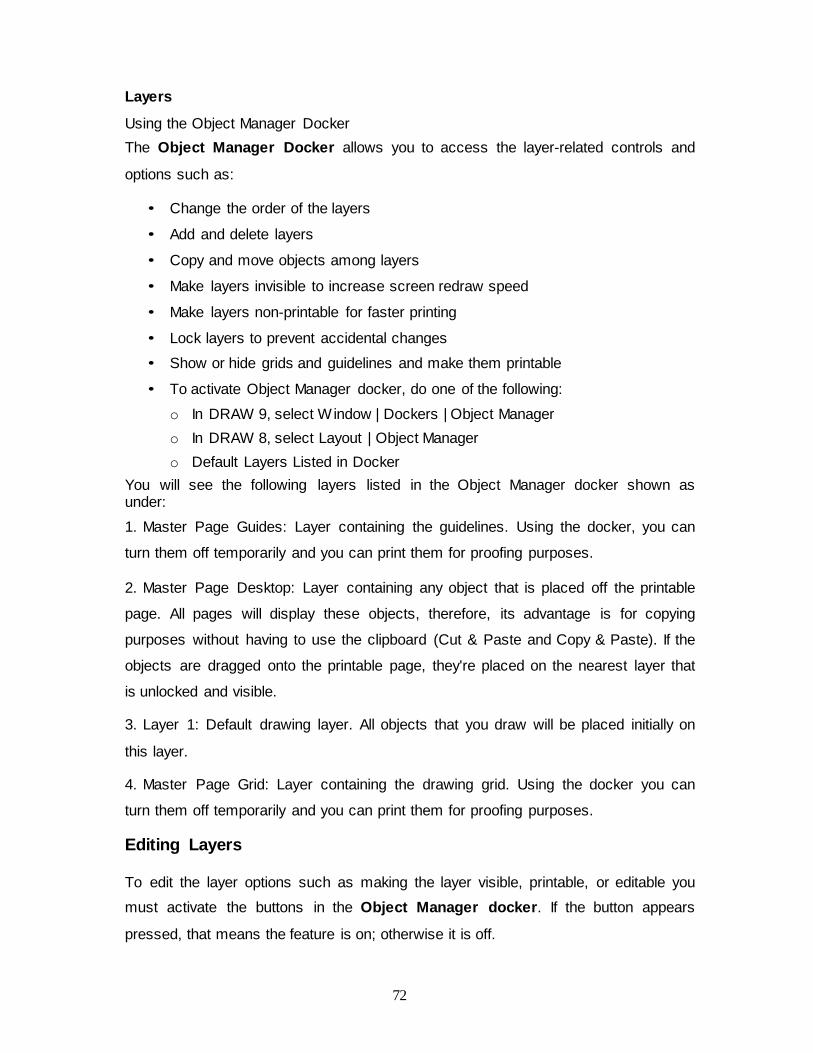
Interactive Mesh Fill Tool
•To add a mesh fill to an object, adjust the nodes in the grid using the shape cursor
to create the desired mesh. Click and drag nodes across the object.
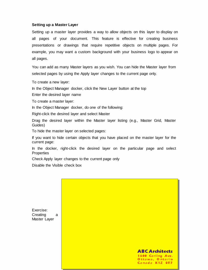
•To change the color of a grid, drag a color from the color palette to the grid.
Before
After
•To adjust the number of boxes in the mesh grid, change the value in the Grid size
boxes on the property bar.
72
Layers
Using the Object Manager Docker
The Object Manager Docker allows you to access the layer-related controls and
options such as:
• Change the order of the layers
• Add and delete layers
• Copy and move objects among layers
• Make layers invisible to increase screen redraw speed
• Make layers non-printable for faster printing
• Lock layers to prevent accidental changes
• Show or hide grids and guidelines and make them printable
• To activate Object Manager docker, do one of the following:
o In DRAW 9, select Window | Dockers | Object Manager
o In DRAW 8, select Layout | Object Manager
o Default Layers Listed in Docker
You will see the following layers listed in the Object Manager docker shown as under:
1. Master Page Guides: Layer containing the guidelines. Using the docker, you can
turn them off temporarily and you can print them for proofing purposes.
2. Master Page Desktop: Layer containing any object that is placed off the printable
page. All pages will display these objects, therefore, its advantage is for copying
purposes without having to use the clipboard (Cut & Paste and Copy & Paste). If the
objects are dragged onto the printable page, they're placed on the nearest layer that
is unlocked and visible.
3. Layer 1: Default drawing layer. All objects that you draw will be placed initially on
this layer.
4. Master Page Grid: Layer containing the drawing grid. Using the docker you can
turn them off temporarily and you can print them for proofing purposes.
Editing Layers
To edit the layer options such as making the layer visible, printable, or editable you
must activate the buttons in the Object Manager docker. If the button appears
pressed, that means the feature is on; otherwise it is off.

73
Figure 3 (at right) "Visible", "Printable", "Editable"
layer icons as displayed in the Object Manager docker.
To edit a layer:
Do one of the following:
• In DRAW 9, select Window | Dockers | Object Manager
• In DRAW 8, select Layout | Object Manager
• The Object Manager docker appears
Do one of the following:
• To turn on the feature, click the button so it appears pressed
• To turn off the feature, click the button so it appears not pressed
To activate a layer:
It's important to make sure one of the layers is set as the active layer. The active
layer name is displayed in a red color in the Object Manager docker. To select
another layer to be the active layer, click on it. It will display in red.
Figure 4 (fig04.tif) The importance of the active layer is that it's displayed in red, in
this case Layer 1.
Observing the Object Manager Docker
In DRAW, create a new document and do one of the following:
• In DRAW 9, select Window | Dockers | Object Manager
• In DRAW 8, select Layout | Object Manager
• The Object Manager docker appears
• Observe the default layer names Master Page Guides, Desktop, Layer 1, and Grids
• Observe Layer 1 is the active layer indicated by its red color
Observe the following:
• Master Page Guides and Desktop layers are not printable
• Master Grid layer is not visible, printable, or editable
• Click the minimize arrows in the top left corner of the docker to temporarily
collapse the docker
74
Setting up a Master Layer
Setting up a master layer provides a way to allow objects on this layer to display on
all pages of your document. This feature is effective for creating business
presentations or drawings that require repetitive objects on multiple pages. For
example, you may want a custom background with your business logo to appear on
all pages.
You can add as many Master layers as you wish. You can hide the Master layer from
selected pages by using the Apply layer changes to the current page only.
To create a new layer:
In the Object Manager docker, click the New Layer button at the top
Enter the desired layer name
To create a master layer:
In the Object Manager docker, do one of the following:
Right-click the desired layer and select Master
Drag the desired layer within the Master layer listing (e.g., Master Grid, Master
Guides)
To hide the master layer on selected pages:
If you want to hide certain objects that you have placed on the master layer for the current page:
In the docker, right-click the desired layer on the particular page and select
Properties
Check Apply layer changes to the current page only
Disable the Visible check box
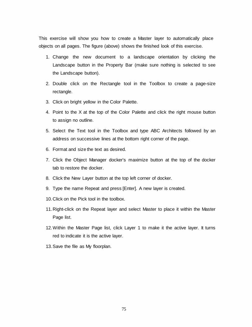
Exercise:
Creating a Master Layer
75
This exercise will show you how to create a Master layer to automatically place
objects on all pages. The figure (above) shows the finished look of this exercise.
1. Change the new document to a landscape orientation by clicking the
Landscape button in the Property Bar (make sure nothing is selected to see
the Landscape button).
2. Double click on the Rectangle tool in the Toolbox to create a page-size
rectangle.
3. Click on bright yellow in the Color Palette.
4. Point to the X at the top of the Color Palette and click the right mouse button
to assign no outline.
5. Select the Text tool in the Toolbox and type ABC Architects followed by an
address on successive lines at the bottom right corner of the page.
6. Format and size the text as desired.
7. Click the Object Manager docker's maximize button at the top of the docker
tab to restore the docker.
8. Click the New Layer button at the top left corner of docker.
9. Type the name Repeat and press [Enter]. A new layer is created.
10. Click on the Pick tool in the toolbox.
11. Right-click on the Repeat layer and select Master to place it within the Master
Page list.
12. Within the Master Page list, click Layer 1 to make it the active layer. It turns
red to indicate it is the active layer.
13. Save the file as My floorplan.
76
Moving, Copying, and Locking Layers
At times, you may need to move or copy objects to another available layer listed in
the Object Manager docker. The objects you move or copy will take on the attributes
defined in the new layer.
Another feature is to lock a layer to prevent any objects on that layer from being
altered or even selected. If you need to alter any objects on a locked layer, you must
first unlock the layer, and then make the changes. When finished, lock the layer
again.
To move or copy objects between layers:
1. Select the object you want to move. Look at the Status Bar to find which layer
the object is currently on.
2. If you're using DRAW 9, click the Layer Manager View button. You do not
have to do this step in DRAW 8.
3. Click the flyout arrow in the Object Manager docker. The flyout menu appears.
Do one of the following:
• To move, select Move To Layer
• To copy, select Copy To Layer
• A black arrow appears
Click on the desired layer in the Object Manager docker to which you want to move
or copy the object. The object is moved or copied to the selected layer.
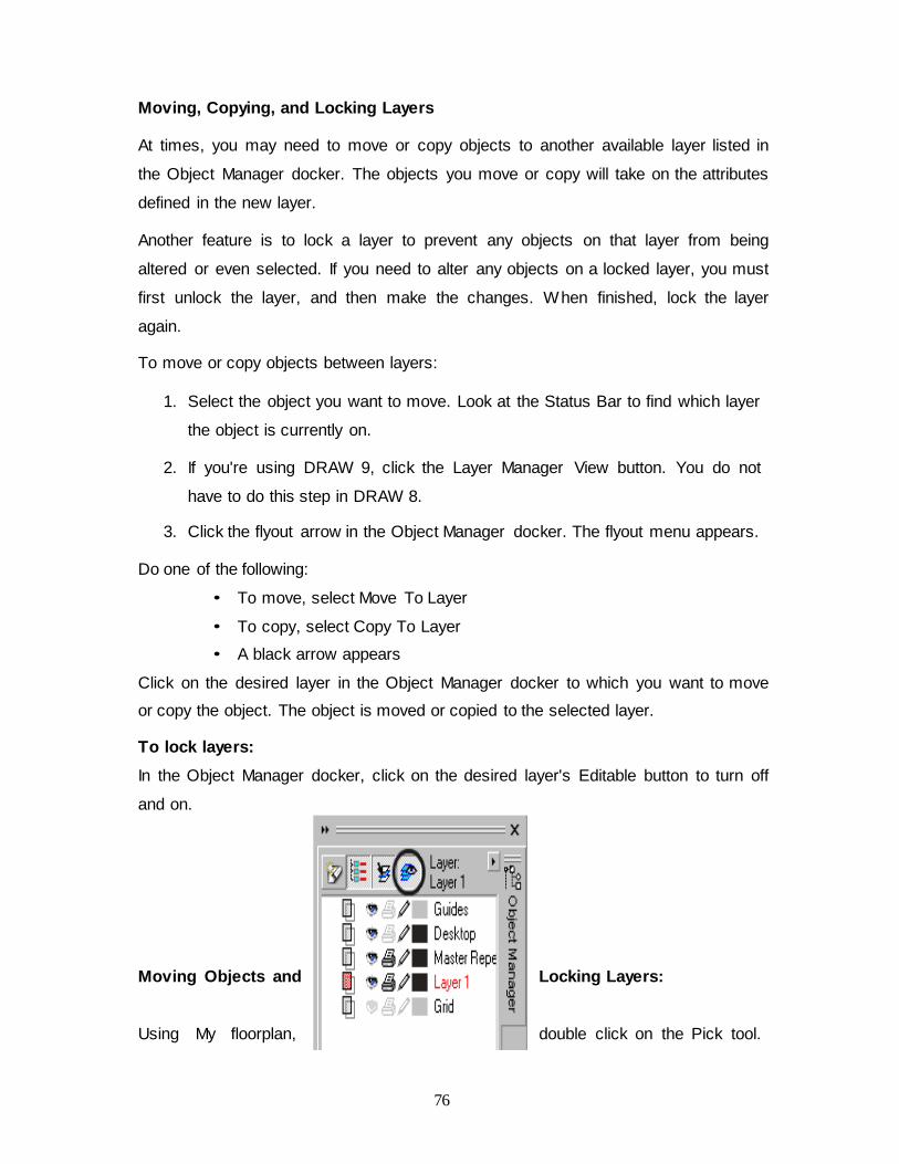
To lock layers:
In the Object Manager docker, click on the desired layer's Editable button to turn off
and on.
Moving Objects and Locking Layers:
Using My floorplan, double click on the Pick tool.
77
Shortcut to select all objects.
Observe the Status Bar to see what layer these objects are on. The objects are on the Layer 1 layer.
If you're using DRAW 9, click the Layer Manager View button. This view shows only
layers without objects or sublevels. You do not have to do this step if you're using
DRAW 8.
Figure 6 (shown above): In DRAW 9, click the Layer Manager View button in order to
activate the Move To and Copy To commands in the flyout menu.
Click on the flyout arrow in the Object Manager docker.
Select Move To Layer. An arrow appears.
Move the arrow on top of the Master Repeat name in the docker and click to move
the objects from Layer 1 to the Repeat layer.
Click on the Master Repeat name in the docker and observe the Status Bar. It
indicates the objects are now on the Repeat layer.
Click on the Master Repeat's Editable (pencil) button to dim it and lock all objects on
the Master Repeat layer.
Select Layout | Insert Page and enter 2 more Landscape pages After Page 1. Click
OK to insert two new pages.
Observe how all objects on the Master layer are repeated on these new pages.
Attempt to select any of the objects on the page. You cannot select these objects
since they are not editable (locked).
In the docker, click on Layer 1 in the docker list to make it the active layer.
Save the file to update My floorplan.
Tips on Moving Objects and Locking
While the steps in the exercise above required you to click on the docker's flyout
arrow to move objects to different layers, you could also drag the objects from the
drawing to the desired layer listed in the Object Manager docker.
You can also lock individual objects by selecting Arrange | Lock Object. To unlock,
select Arrange | Unlock Object.
Reordering the Layers
To change the order of objects on the same layer, you use the Order commands in
the Arrange menu such as To Front, To Back, and so on. However, the order of the
layers still determines the absolute arrangement of all objects in your drawing. The
order in which the layers are listed in the Object Manager is the order that appears
in the drawing. To change their order in the drawing, you must change their order
listed in the docker.
To reorder layers, in the Object Manager, do one of the following:
To reorder a layer higher in the drawing and move its objects on top of other layers,
drag the desired layer up the list.
To reorder a layer lower in the drawing and move its objects below other layers, drag
the desired layer down the list.
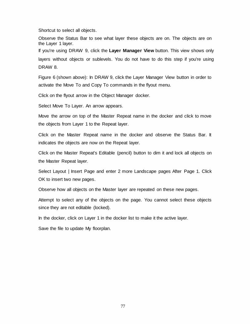
Reordering Layers
Go to page one of My floorplan.
Draw a large rectangle almost as wide as the page and above the ABC business
address and color it white.
Hold on! The rectangle does a vanishing act and seems to
be hiding behind the yellow background. What's going on?!
Well, the answer is displayed in the docker.
Layer 1 is listed below the Master Repeat layer.
Notice that
To fix the disappearing rectangle, drag the Layer 1 name in the docker above Master
Repeat.
The figure (above): Drag Layer 1 above Master Repeat to reorder the layers.
Click the New Layer button in the docker.
Enter Office rooms as the new layer name.
79
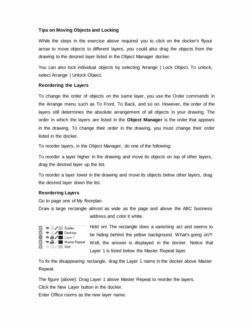
Observe that the Office room layer is listed above Layer 1. This means that any
object on this layer will be placed on top of any objects on Layer 1.
We'll use a series of smaller rectangles to simulate the look of rooms in the floorplan.
Draw about six smaller rectangles forming a 2 row by three-column formation within
the larger rectangle.
Draw a total of six smaller rectangles inside the larger rectangle.
Color the six smaller rectangles blue.
Select each blue rectangle and confirm that they are all on the Office rooms layer (by
looking at the Status Bar).
Click the New Layer button in the docker.
Enter Furniture as the new layer name.
Now we'll use a series of small, red circles to simulate the look of office furniture.
Place the small circles within every blue rectangle as illustrated in the Figure.
Place small, red circles to represent office furniture within each blue rectangle.
Select each red circle and confirm that they are all on the Furniture layer (by looking
at the Status Bar).
80
Save to update My floorplan.
In a complex architectural drawing you could continue to add a layer for plants, a
layer for electrical components, and so on. In our case, we'll keep it simple and
quickly show you the benefits of using layers.
Demonstrating the Benefits of Layers
Using page one of My floorplan, click the Visible icon beside Furniture in the docker.
Notice all furniture (red circles) is temporarily hidden. Hiding layers and their objects
in a complex drawing can save valuable time by avoiding frequent screen refreshes
when editing the document.
Click the Printable (printer) icon beside Furniture in the docker.
Select File, Print Preview. If prompted to automatically change orientation of printer,
click Yes. Notice that the furniture (red circles) is not displayed, therefore will not
print out.
Click Close to exit back to the DRAW screen.
Make the Furniture layer's objects visible and printable (click the Visible and
Printable icons).
This time, make the Master Repeat layer not visible (click the Visible icon).
Check pages two and three. Notice that the objects on the Repeat layer are not
visible on any page.
Continue by making the Master Repeat layer visible again (click the Visible icon).
On page two and three, continue by drawing shapes and objects on specific layers.
Experiment with the options in the docker to become more familiar with the concepts
of layers in DRAW.
Close the Object Manager docker. Click the X in the top right corner.
Save and close the file to update My floorplan.
Self-Check Questionnaire
How do you access the Object Manager docker?
What is the CorelDraw default layer called?
81
List the layer icons that appear above in the Figure:
What are these icons in the docker?
How do you know what layer is currently active?
What is a master layer?
How do you create a master layer?
List how you move objects from one layer to another.
Answers
Select Window | Dockers | Object Manager.
Layer 1.
Visible, printable, editable (left to right).
It displays in red.
Master layer is an option to repeat objects on this layer to all pages.
Right-click on the desired layer in the docker and select Master.
Make sure the Layer Manager View button is pressed, select the object, click on the
flyout arrow in the Object Manager docker, and select Move To Layer. Click arrow on
desired layer listed in the docker. Alternatively, you can drag the object(s) from the
page to the desired layer in the docker.
82
Tracing
Taking Corel PowerTRACE X3 for a Test Drive
Someone hands you a printed logo, when what you really need is a digital vector file-
preferably in CorelDRAW® (CDR) format. If you've run into this scenario before, you
may already know how time consuming the manual conversion process can be.
Adapting images from the physical world into the digital vector realm often requires
hours of work and a mastery of drawing tools. If you own CorelDRAW® Graphics
Suite X3, you've got a powerful tool to help with the heavy lifting! In this tutorial, you'll
discover how easy it is to convert pixels to vector shapes with Corel®
PowerTRACE™ X3. We'll tackle a bitmap-tracing project that will enable you to
quickly produce an accurate two-color vector version of a logo design. Along the
way, you'll learn how to use many of the powerful new features engineered into Corel
PowerTRACE that make the process fast and efficient.
A Primer on Corel PowerTRACE
If this is your first tracing experience using Corel PowerTRACE X3, some advance
orientation may help demystify the tools involved. With a bitmap selected in
CorelDRAW X3, Corel PowerTRACE X3 becomes available through the Trace
Bitmap command on the property bar.
You can instantly trace a selected bitmap using default settings by choosing Quick
Trace from the Trace Bitmap selector, which applies the trace without opening the
PowerTRACE window. There are also six modes that you can choose from
depending on your tracing requirements.
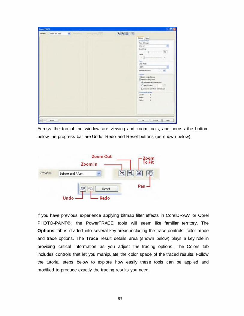
The window (shown below) is divided into two basic areas. The left side of the
window displays a preview of your trace results while the right side features two
option areas.
83
Across the top of the window are viewing and zoom tools, and across the bottom
below the progress bar are Undo, Redo and Reset buttons (as shown below).
If you have previous experience applying bitmap filter effects in CorelDRAW or Corel
PHOTO-PAINT®, the PowerTRACE tools will seem like familiar territory. The
Options tab is divided into several key areas including the trace controls, color mode
and trace options. The Trace result details area (shown below) plays a key role in
providing critical information as you adjust the tracing options. The Colors tab
includes controls that let you manipulate the color space of the traced results. Follow
the tutorial steps below to explore how easily these tools can be applied and
modified to produce exactly the tracing results you need.
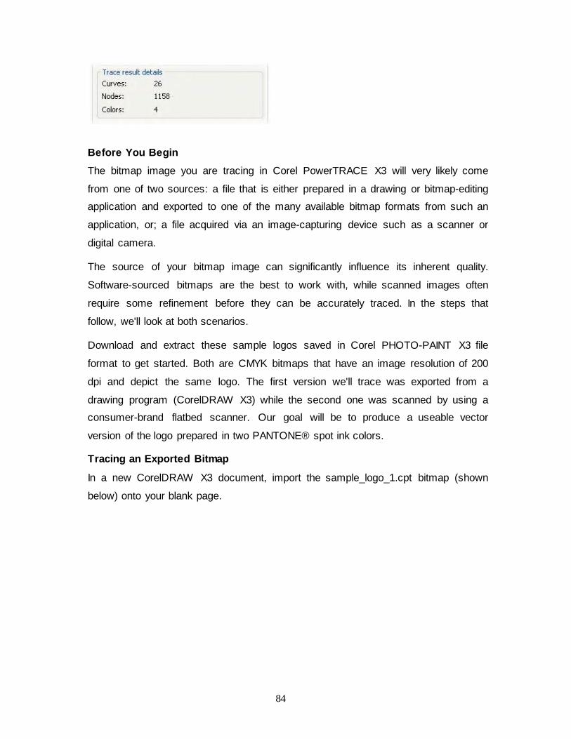
84
Before You Begin
The bitmap image you are tracing in Corel PowerTRACE X3 will very likely come
from one of two sources: a file that is either prepared in a drawing or bitmap-editing
application and exported to one of the many available bitmap formats from such an
application, or; a file acquired via an image-capturing device such as a scanner or
digital camera.
The source of your bitmap image can significantly influence its inherent quality.
Software-sourced bitmaps are the best to work with, while scanned images often
require some refinement before they can be accurately traced. In the steps that
follow, we'll look at both scenarios.
Download and extract these sample logos saved in Corel PHOTO-PAINT X3 file
format to get started. Both are CMYK bitmaps that have an image resolution of 200
dpi and depict the same logo. The first version we'll trace was exported from a
drawing program (CorelDRAW X3) while the second one was scanned by using a
consumer-brand flatbed scanner. Our goal will be to produce a useable vector
version of the logo prepared in two PANTONE® spot ink colors.
Tracing an Exported Bitmap
In a new CorelDRAW X3 document, import the sample_logo_1.cpt bitmap (shown
below) onto your blank page.
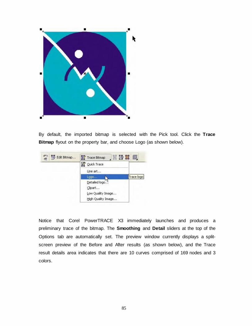
85
By default, the imported bitmap is selected with the Pick tool. Click the Trace
Bitmap flyout on the property bar, and choose Logo (as shown below).
Notice that Corel PowerTRACE X3 immediately launches and produces a
preliminary trace of the bitmap. The Smoothing and Detail sliders at the top of the
Options tab are automatically set. The preview window currently displays a split-
screen preview of the Before and After results (as shown below), and the Trace
result details area indicates that there are 10 curves comprised of 169 nodes and 3
colors.

86
Since the background of our logo sample is white, Corel PowerTRACE X3
automatically detects and eliminates the surrounding background color. To remove
the white area in the interior of the bitmap, enable the Remove color from entire
image check box (shown below). Notice the Trace result details area now indicates
that only 7 curves are detected.
To check the tracing accuracy, choose Wireframe Overlay from the Preview list
box. Use single left-button clicks to zoom in and single right-button clicks to zoom out
to examine the accuracy of the traced paths. If needed, use the Transparency slider
to adjust the visibility of the original bitmap. A close look at the upper-left corner
(shown below) reveals the bitmap edges have been accurately traced.
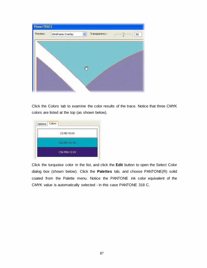
87
Click the Colors tab to examine the color results of the trace. Notice that three CMYK
colors are listed at the top (as shown below).
Click the turquoise color in the list, and click the Edit button to open the Select Color
dialog box (shown below). Click the Palettes tab, and choose PANTONE(R) solid
coated from the Palette menu. Notice the PANTONE ink color equivalent of the
CMYK value is automatically selected - in this case PANTONE 318 C.
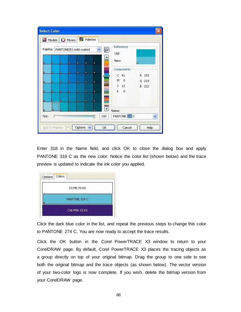
88
Enter 318 in the Name field, and click OK to close the dialog box and apply
PANTONE 318 C as the new color. Notice the color list (shown below) and the trace
preview is updated to indicate the ink color you applied.
Click the dark blue color in the list, and repeat the previous steps to change this color
to PANTONE 274 C. You are now ready to accept the trace results.
Click the OK button in the Corel PowerTRACE X3 window to return to your
CorelDRAW page. By default, Corel PowerTRACE X3 places the tracing objects as
a group directly on top of your original bitmap. Drag the group to one side to see
both the original bitmap and the trace objects (as shown below). The vector version
of your two-color logo is now complete. If you wish, delete the bitmap version from
your CorelDRAW page.

89
Tracing a Scanned Bitmap
In the previous steps, you traced a bitmap that originated from a drawing or bitmap-
editing application. Next, we'll examine how to work with the same logo image
scanned from a color hard copy and saved in the same bitmap format.
To begin the process, import sample_logo_2.cpt into your CorelDRAW X3
document, and choose Detailed logo from the Trace Bitmap flyout on the property
bar. Corel PowerTRACE X3 launches and a preliminary trace is immediately
produced. Now the Trace result details area shows that 113 curves, 7707 nodes,
and 15 colors are detected (as shown below). At this point we could move the
Smoothing and Detail sliders to adjust the trace results and likely produce an
excellent trace, but here's a chance for you to learn an alternate strategy.
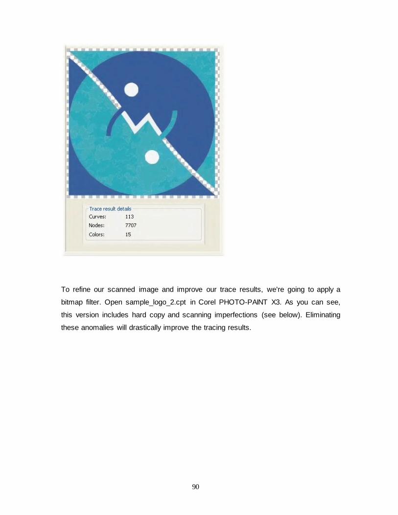
90
To refine our scanned image and improve our trace results, we're going to apply a
bitmap filter. Open sample_logo_2.cpt in Corel PHOTO-PAINT X3. As you can see,
this version includes hard copy and scanning imperfections (see below). Eliminating
these anomalies will drastically improve the tracing results.

91
Choose Effects > Blur > Smart Blur to open the Smart Blur dialog box (shown
below). Set the slider to 60, and click OK to apply the effect. This operation will
eliminate most – but not all – of the image's imperfections.
Choose Effects > Noise > Remove Noise to open the Remove Noise dialog box
(shown below). Leave the Auto check box enabled, and click the OK button to apply
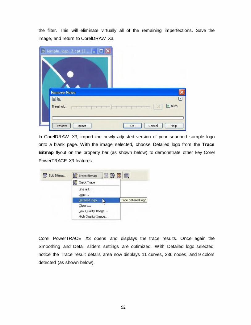
92
the filter. This will eliminate virtually all of the remaining imperfections. Save the
image, and return to CorelDRAW X3.
In CorelDRAW X3, import the newly adjusted version of your scanned sample logo
onto a blank page. With the image selected, choose Detailed logo from the Trace
Bitmap flyout on the property bar (as shown below) to demonstrate other key Corel
PowerTRACE X3 features.
Corel PowerTRACE X3 opens and displays the trace results. Once again the
Smoothing and Detail sliders settings are optimized. With Detailed logo selected,
notice the Trace result details area now displays 11 curves, 236 nodes, and 9 colors
detected (as shown below).
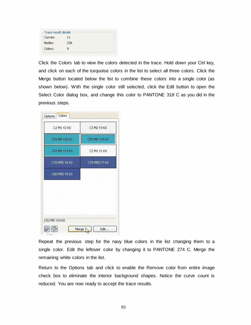
93
Click the Colors tab to view the colors detected in the trace. Hold down your Ctrl key,
and click on each of the turquoise colors in the list to select all three colors. Click the
Merge button located below the list to combine these colors into a single color (as
shown below). With the single color still selected, click the Edit button to open the
Select Color dialog box, and change this color to PANTONE 318 C as you did in the
previous steps.
Repeat the previous step for the navy blue colors in the list changing them to a
single color. Edit the leftover color by changing it to PANTONE 274 C. Merge the
remaining white colors in the list.
Return to the Options tab and click to enable the Remove color from entire image
check box to eliminate the interior background shapes. Notice the curve count is
reduced. You are now ready to accept the trace results.
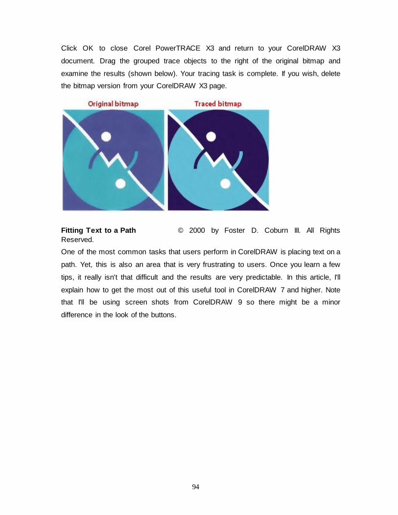
94
Click OK to close Corel PowerTRACE X3 and return to your CorelDRAW X3
document. Drag the grouped trace objects to the right of the original bitmap and
examine the results (shown below). Your tracing task is complete. If you wish, delete
the bitmap version from your CorelDRAW X3 page.
Fitting Text to a Path © 2000 by Foster D. Coburn III. All Rights
Reserved.
One of the most common tasks that users perform in CorelDRAW is placing text on a
path. Yet, this is also an area that is very frustrating to users. Once you learn a few
tips, it really isn't that difficult and the results are very predictable. In this article, I'll
explain how to get the most out of this useful tool in CorelDRAW 7 and higher. Note
that I'll be using screen shots from CorelDRAW 9 so there might be a minor
difference in the look of the buttons.
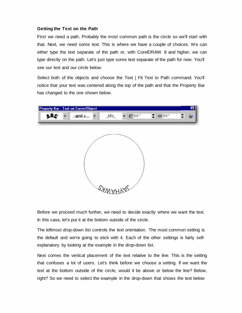
Getting the Text on the Path
First we need a path. Probably the most common path is the circle so we'll start with
that. Next, we need some text. This is where we have a couple of choices. We can
either type the text separate of the path or, with CorelDRAW 8 and higher, we can
type directly on the path. Let's just type some text separate of the path for now. You'll
see our text and our circle below.
Select both of the objects and choose the Text | Fit Text to Path command. You'll
notice that your text was centered along the top of the path and that the Property Bar
has changed to the one shown below.
Before we proceed much further, we need to decide exactly where we want the text.
In this case, let's put it at the bottom outside of the circle.
The leftmost drop-down list controls the text orientation. The most common setting is
the default and we're going to stick with it. Each of the other settings is fairly self-
explanatory by looking at the example in the drop-down list.
Next comes the vertical placement of the text relative to the line. This is the setting
that confuses a lot of users. Let's think before we choose a setting. If we want the
text at the bottom outside of the circle, would it be above or below the line? Below,
right? So we need to select the example in the drop-down that shows the text below
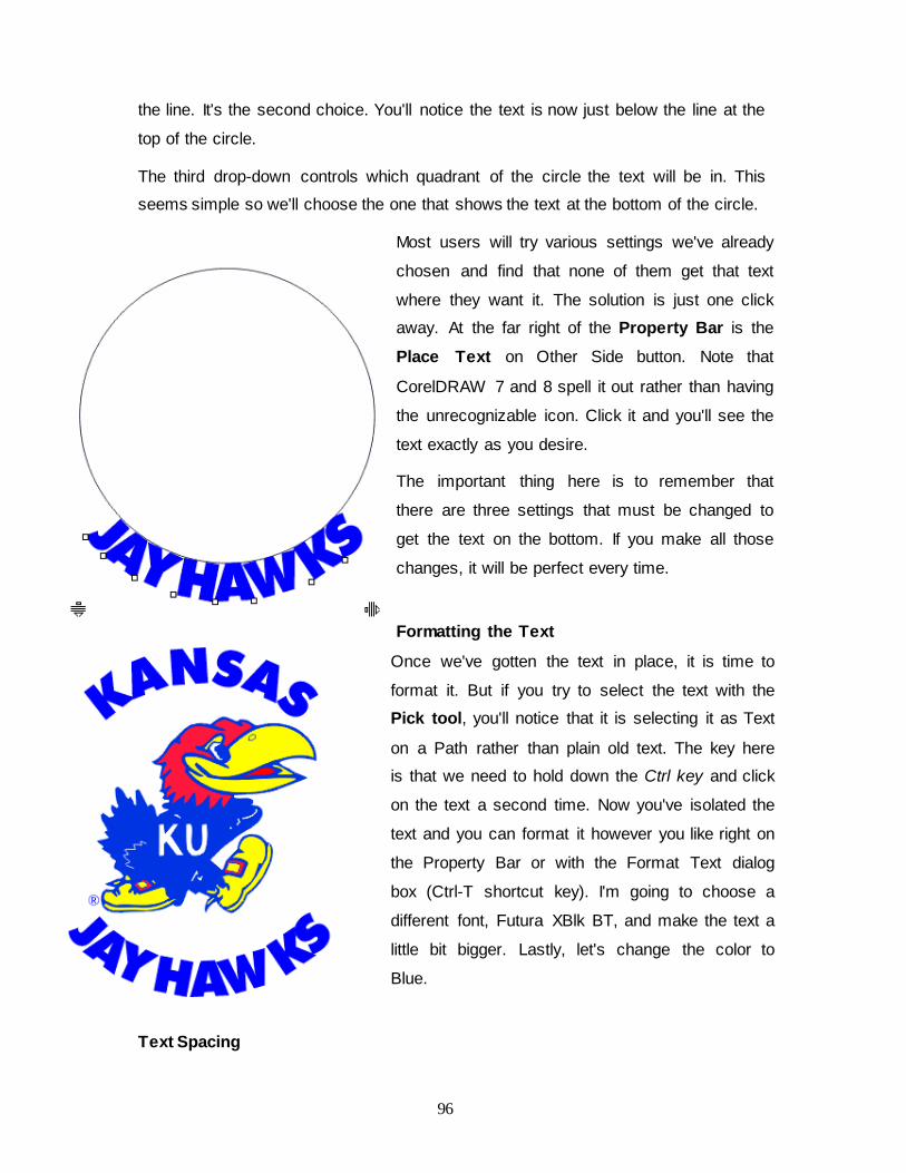
96
the line. It's the second choice. You'll notice the text is now just below the line at the
top of the circle.
The third drop-down controls which quadrant of the circle the text will be in. This
seems simple so we'll choose the one that shows the text at the bottom of the circle.
Most users will try various settings we've already
chosen and find that none of them get that text
where they want it. The solution is just one click
away. At the far right of the Property Bar is the
Place Text on Other Side button. Note that
CorelDRAW 7 and 8 spell it out rather than having
the unrecognizable icon. Click it and you'll see the
text exactly as you desire.
The important thing here is to remember that
there are three settings that must be changed to
get the text on the bottom. If you make all those
changes, it will be perfect every time.
Formatting the Text
Once we've gotten the text in place, it is time to
format it. But if you try to select the text with the
Pick tool, you'll notice that it is selecting it as Text
on a Path rather than plain old text. The key here
is that we need to hold down the Ctrl key and click
on the text a second time. Now you've isolated the
text and you can format it however you like right on
the Property Bar or with the Format Text dialog
box (Ctrl-T shortcut key). I'm going to choose a
different font, Futura XBlk BT, and make the text a
little bit bigger. Lastly, let's change the color to
Blue.
Text Spacing
97
In my example, I'm pretty lucky as the text spacing seems pretty darned good. But
you'll often have some weird looking spacing that needs to be corrected. This is
especially true when you have a more irregular path. In these cases, we'll need to
manually adjust the character placement until we are happy with the result. To do
this, first you need to isolate the text as we did when formatting the text. Then you
want to choose the Shape tool (some of you probably call it the Node Edit tool).
When you do this, you'll see a small square at the lower left of each character and
you'll also see some funny looking arrows at the lower right and lower left of the
entire text block as shown at right.
To quickly change the spacing between all characters, click and drag on the funny
arrow at the lower right of the text block. It controls the inter-character spacing. If you
drag to the right, the spacing will increase while dragging to the left will decrease the
space.
If you still feel like tweaking the text further, click on the node at the lower left of the
character and you can drag that character along the path. You can even marquee
select several nodes to move a series of characters together.
Finishing It Up
Now that we've finished the hard part, we'll repeat our steps to put text on the top of
the circle. If you'll remember, this is the default setting. So you type the text, select
both the text and the path and choose the Text | Fit Text to Path command. The
other steps for formatting and spacing are exactly the same.
One of the most common questions asked by CorelDRAW users is how to use the
Corel OCR-TRACE utility to convert bitmap artwork into vector artwork. The
instructions given here should work in CorelDRAW 3 through CorelDRAW X4.
Part of the problem with tracing bitmaps is the quality of the original artwork. Our
clients don't seem to understand that the quality of the finished product is highly
dependent on the quality of the artwork that we receive. So it is your job as the artist
to explain this to the client. Show them examples of good artwork and bad artwork.
Explain how good artwork can save you time and thus save money for the client.
And while they are saving money, they will also receive higher quality. This applies
no matter what method you will be using to convert their artwork from a bitmap to a
vector. But we all know that clients just love to hand us a business card from which

we are to extract their logo. So I looked over my desk and found a business card
with a logo that was quite small and scanned it in so that I'm working with something
similar to what you might have. In my case, it is an ARA business card and we'll
recreate the ARA logo.
Note: For those who aren't familiar with the ARA, they are an organization that deals
with the awards and promotional products. A large majority of their members are
also CorelDRAW users.
If the artwork is 2-color (black and white), make sure to scan in black and white. This
keeps the file size smaller and the extra grayscale or color data would provide no
benefit. Scan at the highest
optical resolution of your scanner. For most desktop
scanners this is between 300 and 600 dpi. I've purposely scanned the ARA logo at a
fairly low resolution so that the quality isn't that great. An example of
shown below:
my scan is
Now you need to import the bitmap into CorelDRAW. Those of you using
CorelDRAW 3 through 7 will need to create a new layer and place the bitmap onto
this new layer. With the bitmap selected, right-click on a lighter color
in the color
palette. I've used Red. Now anything that was Black in the logo will be Red. This
makes it much easier to see what you will be creating. Users of CorelDRAW 8 can
lock the object so that it won't be accidentally moved while users of older versions
will need to lock the layer that you created for the bitmap and then
switch to a

99
different layer. In CorelDRAW 8, right-click on the bitmap and select Lock Object
from the pop-up menu.
Now we're ready to start recreating. Since this logo is primarily text, I'd start by trying
to find a font that matches. The letters ARA initially appear to be a font called Revue
so I loaded that font and typed the letters AR. The last A is simply a reversal of the
first so I'll
add that later. My guess at a font was close, but not perfect as you can see below.
I've switched to wireframe view so that I can see the outlines of the text in relation to
the bitmap.

100
Since this font is close, I'd probably convert it to curves and shape the curves until
they were just right. But I'm going to recreate it from scratch as that is the more
difficult method for recreating artwork. Before I start the actual creation, I want to add
guidelines anywhere where there are straight lines in our artwork. This will help me
to make sure that lines will be straight in these areas and that they align across the
whole logo.
The Figure below shows the file after I've brought in several guidelines.

101
Now the last part is the part where most users give up. Choose the Bezier tool (it is
the second tool on the Freehand tool flyout). This will allow you to create a node at
each point you click. If you simply click, a straight line will be created between the
previous node and the current node. But you can also click and drag to shape the
curve as you draw. If you've never used this tool before, it will take you some time
before you are comfortable using it. For a half an hour, do nothing but draw shapes
with the Bezier tool. At that point, you should feel much better about using it.
Now it is just a case of redrawing the character shapes using the Bezier tool. While
this may seem time consuming, it is much quicker and more accurate in the long run.
Tracing the logo automatically will create a bunch of extra nodes that will need to be
cleaned up. This clean up process will take much longer than recreation if you have
a good grasp of the Bezier tool. After the initial drawing of the logo, there will
undoubtedly be a few mistakes. So switch to the Shape tool and make any

102
necessary changes. It took me about 10 minutes to recreate the main part of the
logo.
Then I needed to recreate the small text that spells out "Awards and Recognition
Association". A quick look at the text and I guessed that it was Times Roman Bold
Italic. I typed in the text and tried various sizes until it matched exactly. I then
adjusted the line spacing until it matched. This took another 2-3 minutes total.
My finished logo is shown below:
Creating Distressed Text in CorelDRAW © 2003 Hunter Elliott.
Distressed text can take on many shapes and sizes, obviously. However, most of the
distressed text effects one sees are usually either various texture effects to text in
bitmap applications or they're fonts that are already distressed.

There are times, though that you really want something just a bit different than what
everyone else is putting out there in the graphics world and you want it as a purely
vector object. Enter the Artistic Media brush.
Let's start out in CorelDRAW with some text. I've chosen a fairly fat font (Futura
Extra Black) and sized it fairly large for this tutorial (72pt).
To work our text with the Artistic Media brushes, we need to convert our text to an
object, so hit Ctrl-Q to convert the text to curves. Now open up the Artistic Media
Docker (Window | Dockers
| Artistic Media). Let's just use the very
first stroke
available. Just left-click the stroke and drag it on top of the "text" you want to distress
(or just make sure the text is selected and click on the stroke you want to use).
The default settings of the tool may be too "fat" to keep the text legible. With your
text selected by the Artistic Media brush, you'll see on the Property Bar the Artistic
Media Tool Width setting—just manually enter in a value or click up/down on the
arrow
to
the width
tool to a
you like.
buttons
change
of the
setting
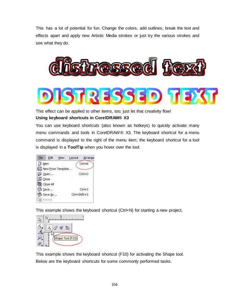
104
This has a lot of potential for fun. Change the colors, add outlines, break the text and
effects apart and apply new Artistic Media strokes or just try the various strokes and
see what they do.
This effect can be applied to other items, too; just let that creativity flow!
Using keyboard shortcuts in CorelDRAW® X3
You can use keyboard shortcuts (also known as hotkeys) to quickly activate many
menu commands and tools in CorelDRAW® X3. The keyboard shortcut for a menu
command is displayed to the right of the menu item; the keyboard shortcut for a tool
is displayed in a ToolTip when you hover over the tool.
This example shows the keyboard shortcut (Ctrl+N) for starting a new project.
This example shows the keyboard shortcut (F10) for activating the Shape tool.
Below are the keyboard shortcuts for some commonly performed tasks.
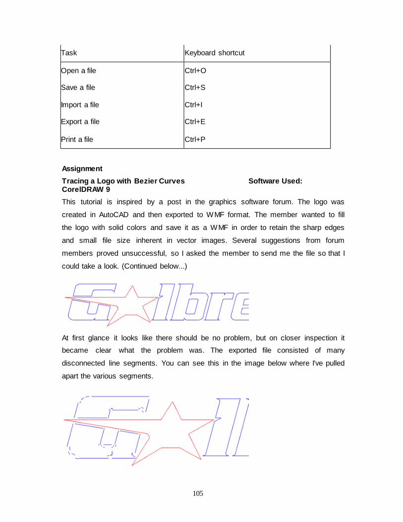
105
Task
Keyboard shortcut
Open a file
Ctrl+O
Save a file
Ctrl+S
Import a file
Ctrl+I
Export a file
Ctrl+E
Print a file
Ctrl+P
Assignment
Tracing a Logo with Bezier Curves Software Used: CorelDRAW 9
This tutorial is inspired by a post in the graphics software forum. The logo was
created in AutoCAD and then exported to WMF format. The member wanted to fill
the logo with solid colors and save it as a WMF in order to retain the sharp edges
and small file size inherent in vector images. Several suggestions from forum
members proved unsuccessful, so I asked the member to send me the file so that I
could take a look. (Continued below...)
At first glance it looks like there should be no problem, but on closer inspection it
became clear what the problem was. The exported file consisted of many
disconnected line segments. You can see this in the image below where I've pulled
apart the various segments.
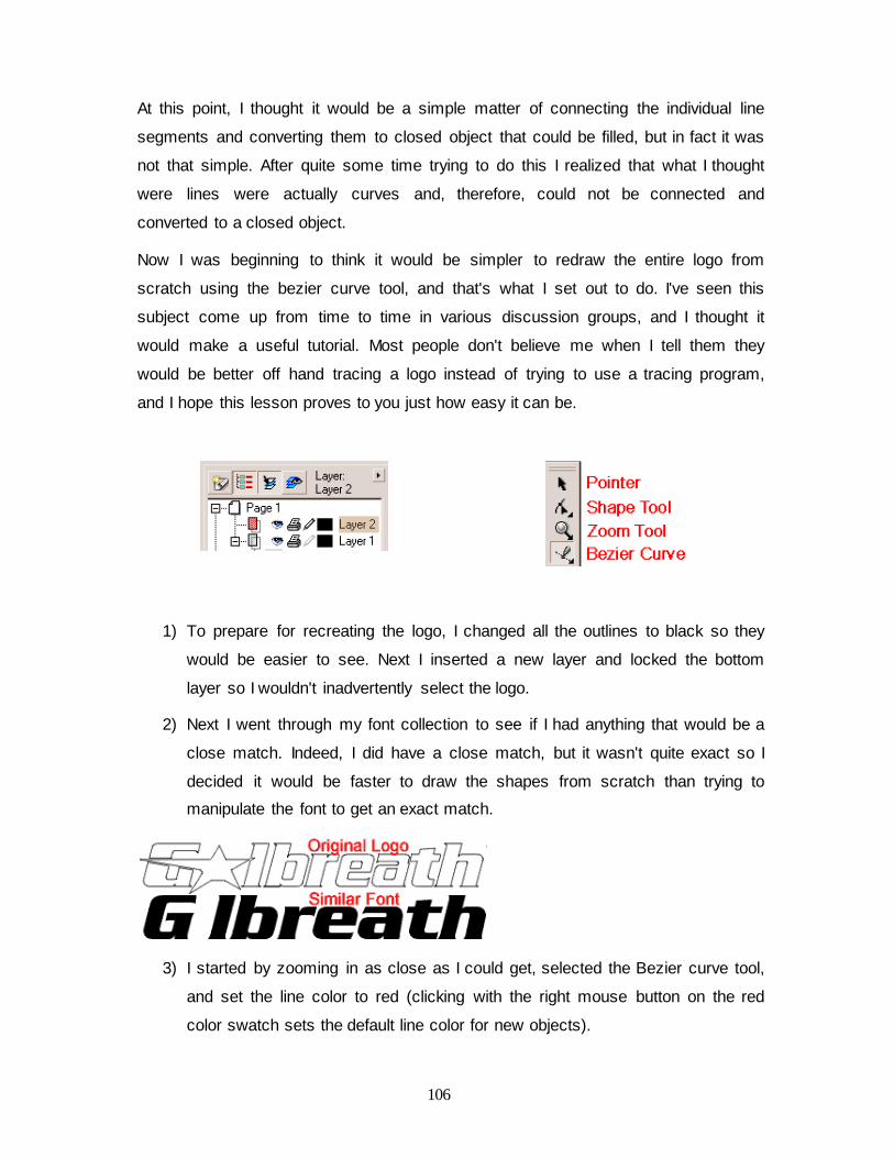
106
At this point, I thought it would be a simple matter of connecting the individual line
segments and converting them to closed object that could be filled, but in fact it was
not that simple. After quite some time trying to do this I realized that what I thought
were lines were actually curves and, therefore, could not be connected and
converted to a closed object.
Now I was beginning to think it would be simpler to redraw the entire logo from
scratch using the bezier curve tool, and that's what I set out to do. I've seen this
subject come up from time to time in various discussion groups, and I thought it
would make a useful tutorial. Most people don't believe me when I tell them they
would be better off hand tracing a logo instead of trying to use a tracing program,
and I hope this lesson proves to you just how easy it can be.
1) To prepare for recreating the logo, I changed all the outlines to black so they
would be easier to see. Next I inserted a new layer and locked the bottom
layer so I wouldn't inadvertently select the logo.
2) Next I went through my font collection to see if I had anything that would be a
close match. Indeed, I did have a close match, but it wasn't quite exact so I
decided it would be faster to draw the shapes from scratch than trying to
manipulate the font to get an exact match.
3) I started by zooming in as close as I could get, selected the Bezier curve tool,
and set the line color to red (clicking with the right mouse button on the red
color swatch sets the default line color for new objects).
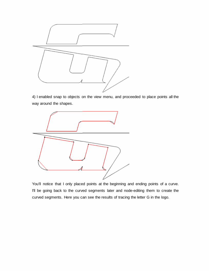
4) I enabled snap to objects on the view menu, and proceeded to place points all the
way around the shapes.
You'll notice that I only placed points at the beginning and ending points of a curve.
I'll be going back to the curved segments later and node-editing them to create the
curved segments. Here you can see the results of tracing the letter G in the logo.
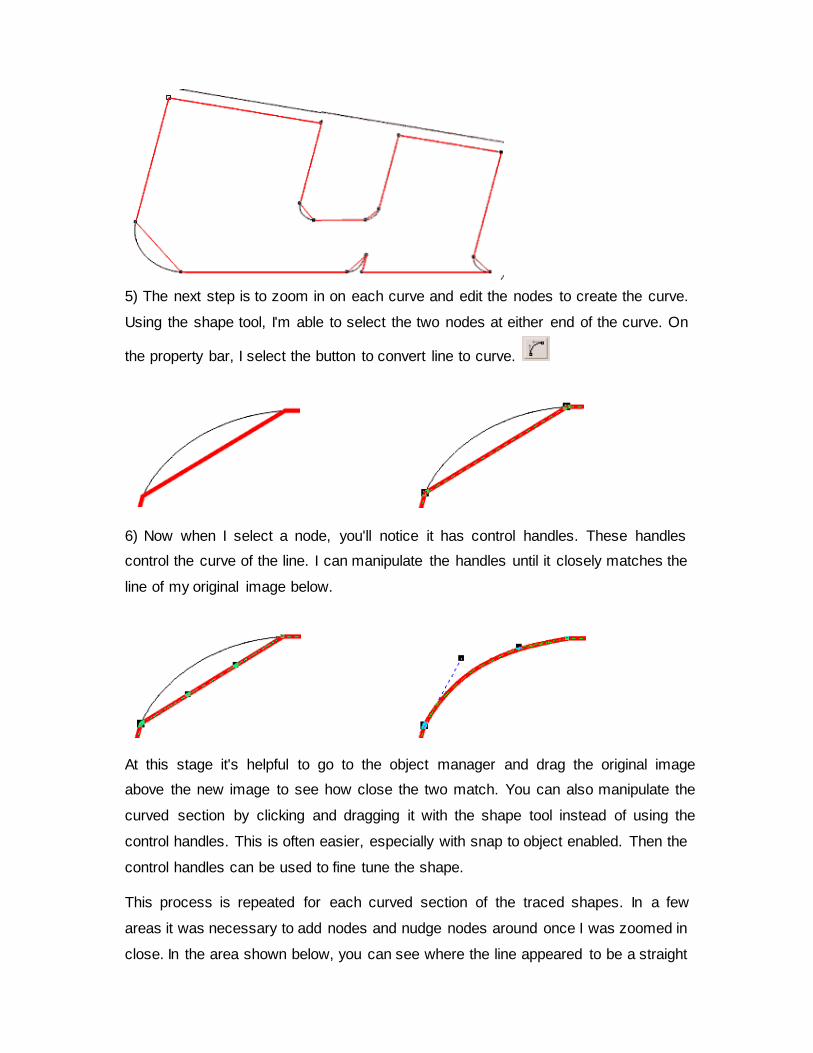
5) The next step is to zoom in on each curve and edit the nodes to create the curve.
Using the shape tool, I'm able to select the two nodes at either end of the curve. On
the property bar, I select the button to convert line to curve.
6) Now when I select a node, you'll notice it has control handles. These handles
control the curve of the line. I can manipulate the handles until it closely matches the
line of my original image below.
At this stage it's helpful to go to the object manager and drag the original image
above the new image to see how close the two match. You can also manipulate the
curved section by clicking and dragging it with the shape tool instead of using the
control handles. This is often easier, especially with snap to object enabled. Then the
control handles can be used to fine tune the shape.
This process is repeated for each curved section of the traced shapes. In a few
areas it was necessary to add nodes and nudge nodes around once I was zoomed in
close. In the area shown below, you can see where the line appeared to be a straight
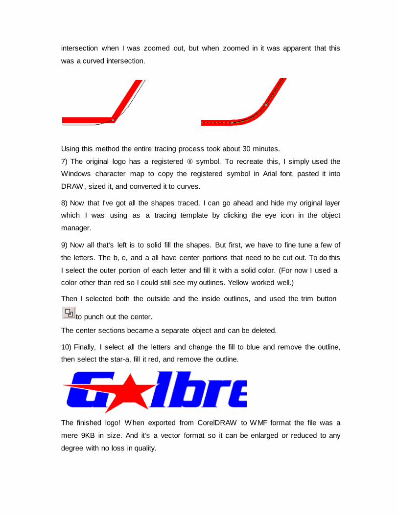
intersection when I was zoomed out, but when zoomed in it was apparent that this
was a curved intersection.
Using this method the entire tracing process took about 30 minutes.
7) The original logo has a registered ® symbol. To recreate this, I simply used the
Windows character map to copy the registered symbol in Arial font, pasted it into
DRAW, sized it, and converted it to curves.
8) Now that I've got all the shapes traced, I can go ahead and hide my original layer
which I was using as a tracing template by clicking the eye icon in the object
manager.
9) Now all that's left is to solid fill the shapes. But first, we have to fine tune a few of
the letters. The b, e, and a all have center portions that need to be cut out. To do this
I select the outer portion of each letter and fill it with a solid color. (For now I used a
color other than red so I could still see my outlines. Yellow worked well.)
Then I selected both the outside and the inside outlines, and used the trim button
to punch out the center.
The center sections became a separate object and can be deleted.
10) Finally, I select all the letters and change the fill to blue and remove the outline,
then select the star-a, fill it red, and remove the outline.
The finished logo! When exported from CorelDRAW to WMF format the file was a
mere 9KB in size. And it's a vector format so it can be enlarged or reduced to any
degree with no loss in quality.
110
Bevels Effect
Create Beautiful Bevels with CorelDRAW® X3 By Steve Bain
Applying bevels to graphics with earlier versions of CorelDRAW® was certainly not
simple and easy, and the results were arguably less than impressive. However, all
that has changed with the introduction of the new bevel effect in CorelDRAW X3.
You can now add a third dimension (see below) and customize your bevels with
depth, color, and lighting options. This new feature is a welcome addition to the
effects available in CorelDRAW.
Besides being completely customizable, the bevels you can create are dynamically
linked to the source object they're applied to, so you can always adjust and edit your
bevel creations. CorelDRAW X3 also enables you to specify full CMYK or spot
colors, which makes this effect extremely versatile.
Fast and Easy Bevels
All of the controls you need to apply a bevel effect are found in the Bevel docker.
You can apply your bevels to virtually any closed vector shape, provided you haven't
already applied other complex effects to it. Closed vector shapes include artistic text,
native shapes (such as rectangles, ellipses, and polygons), and any other shapes
you can imagine.
Options in the Bevel docker are organized into Style, Bevel Offset, Shadow Color,
and Light controls, with the last group of controls providing the most flexibility (see
below). After your options are set, you can apply or update the bevels by clicking the
Apply button.
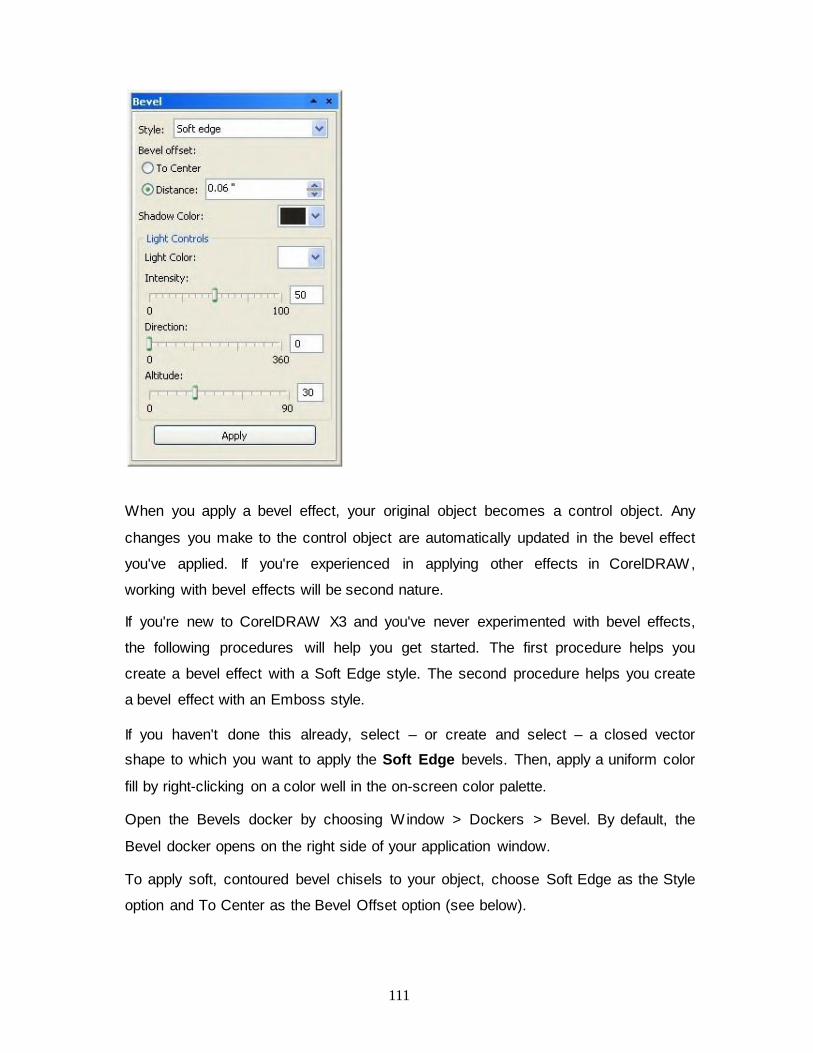
111
When you apply a bevel effect, your original object becomes a control object. Any
changes you make to the control object are automatically updated in the bevel effect
you've applied. If you're experienced in applying other effects in CorelDRAW,
working with bevel effects will be second nature.
If you're new to CorelDRAW X3 and you've never experimented with bevel effects,
the following procedures will help you get started. The first procedure helps you
create a bevel effect with a Soft Edge style. The second procedure helps you create
a bevel effect with an Emboss style.
If you haven't done this already, select – or create and select – a closed vector
shape to which you want to apply the Soft Edge bevels. Then, apply a uniform color
fill by right-clicking on a color well in the on-screen color palette.
Open the Bevels docker by choosing Window > Dockers > Bevel. By default, the
Bevel docker opens on the right side of your application window.
To apply soft, contoured bevel chisels to your object, choose Soft Edge as the Style
option and To Center as the Bevel Offset option (see below).
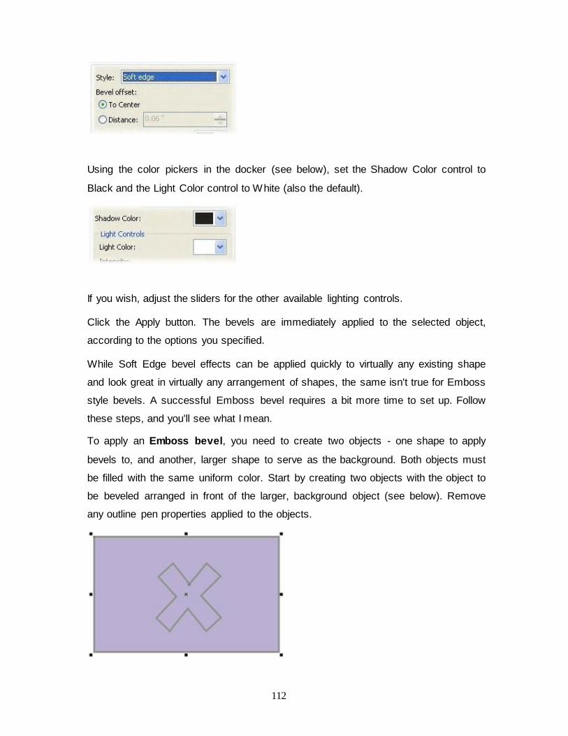
112
Using the color pickers in the docker (see below), set the Shadow Color control to
Black and the Light Color control to White (also the default).
If you wish, adjust the sliders for the other available lighting controls.
Click the Apply button. The bevels are immediately applied to the selected object,
according to the options you specified.
While Soft Edge bevel effects can be applied quickly to virtually any existing shape
and look great in virtually any arrangement of shapes, the same isn't true for Emboss
style bevels. A successful Emboss bevel requires a bit more time to set up. Follow
these steps, and you'll see what I mean.
To apply an Emboss bevel, you need to create two objects - one shape to apply
bevels to, and another, larger shape to serve as the background. Both objects must
be filled with the same uniform color. Start by creating two objects with the object to
be beveled arranged in front of the larger, background object (see below). Remove
any outline pen properties applied to the objects.
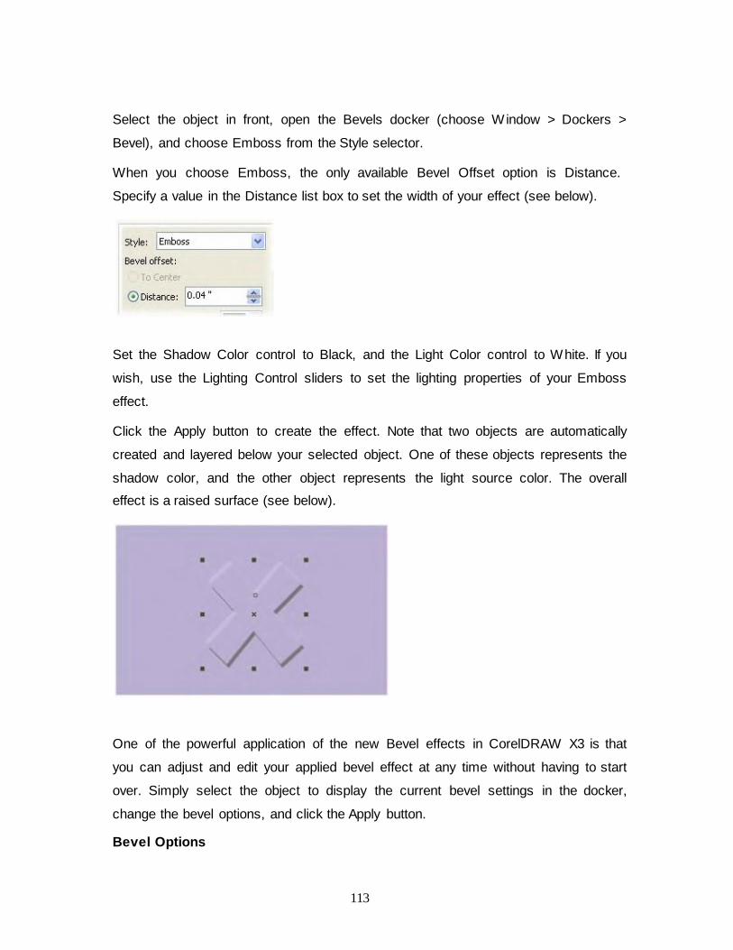
113
Select the object in front, open the Bevels docker (choose Window > Dockers >
Bevel), and choose Emboss from the Style selector.
When you choose Emboss, the only available Bevel Offset option is Distance.
Specify a value in the Distance list box to set the width of your effect (see below).
Set the Shadow Color control to Black, and the Light Color control to White. If you
wish, use the Lighting Control sliders to set the lighting properties of your Emboss
effect.
Click the Apply button to create the effect. Note that two objects are automatically
created and layered below your selected object. One of these objects represents the
shadow color, and the other object represents the light source color. The overall
effect is a raised surface (see below).
One of the powerful application of the new Bevel effects in CorelDRAW X3 is that
you can adjust and edit your applied bevel effect at any time without having to start
over. Simply select the object to display the current bevel settings in the docker,
change the bevel options, and click the Apply button.
Bevel Options
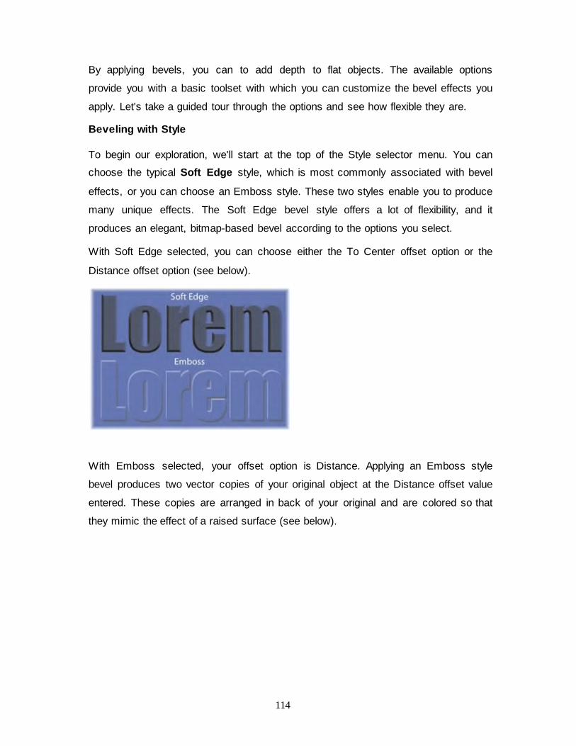
114
By applying bevels, you can to add depth to flat objects. The available options
provide you with a basic toolset with which you can customize the bevel effects you
apply. Let's take a guided tour through the options and see how flexible they are.
Beveling with Style
To begin our exploration, we'll start at the top of the Style selector menu. You can
choose the typical Soft Edge style, which is most commonly associated with bevel
effects, or you can choose an Emboss style. These two styles enable you to produce
many unique effects. The Soft Edge bevel style offers a lot of flexibility, and it
produces an elegant, bitmap-based bevel according to the options you select.
With Soft Edge selected, you can choose either the To Center offset option or the
Distance offset option (see below).
With Emboss selected, your offset option is Distance. Applying an Emboss style
bevel produces two vector copies of your original object at the Distance offset value
entered. These copies are arranged in back of your original and are colored so that
they mimic the effect of a raised surface (see below).

115
You can produce different effects with Soft Edge bevels, depending on whether you
choose the To Center offset or the Distance offset. The To Center offset applies
contoured bevels that join the outer edges of your object to the center, creating a
ridge or crest effect along the center of the shape. With the Distance offset option,
you can specify the offset value, which enables you to control the bevel depth. The
unbeveled portion of your object's surface is left flat (see below).
Setting Light and Shadow Colors
The uniform color fill that you apply to your control object influences the overall color
and, in fact, serves as the foundation for lighting and shadow colors. Keep this in
mind as we look at the next two, interrelated variables of your bevel that you can
control: shadow color and light color.
Shadows automatically appear on the simulated side that faces away from the
bevel's imaginary light source. The intensity of the shadow is based on its angle from
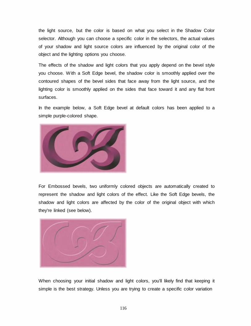
116
the light source, but the color is based on what you select in the Shadow Color
selector. Although you can choose a specific color in the selectors, the actual values
of your shadow and light source colors are influenced by the original color of the
object and the lighting options you choose.
The effects of the shadow and light colors that you apply depend on the bevel style
you choose. With a Soft Edge bevel, the shadow color is smoothly applied over the
contoured shapes of the bevel sides that face away from the light source, and the
lighting color is smoothly applied on the sides that face toward it and any flat front
surfaces.
In the example below, a Soft Edge bevel at default colors has been applied to a
simple purple-colored shape.
For Embossed bevels, two uniformly colored objects are automatically created to
represent the shadow and light colors of the effect. Like the Soft Edge bevels, the
shadow and light colors are affected by the color of the original object with which
they're linked (see below).
When choosing your initial shadow and light colors, you'll likely find that keeping it
simple is the best strategy. Unless you are trying to create a specific color variation
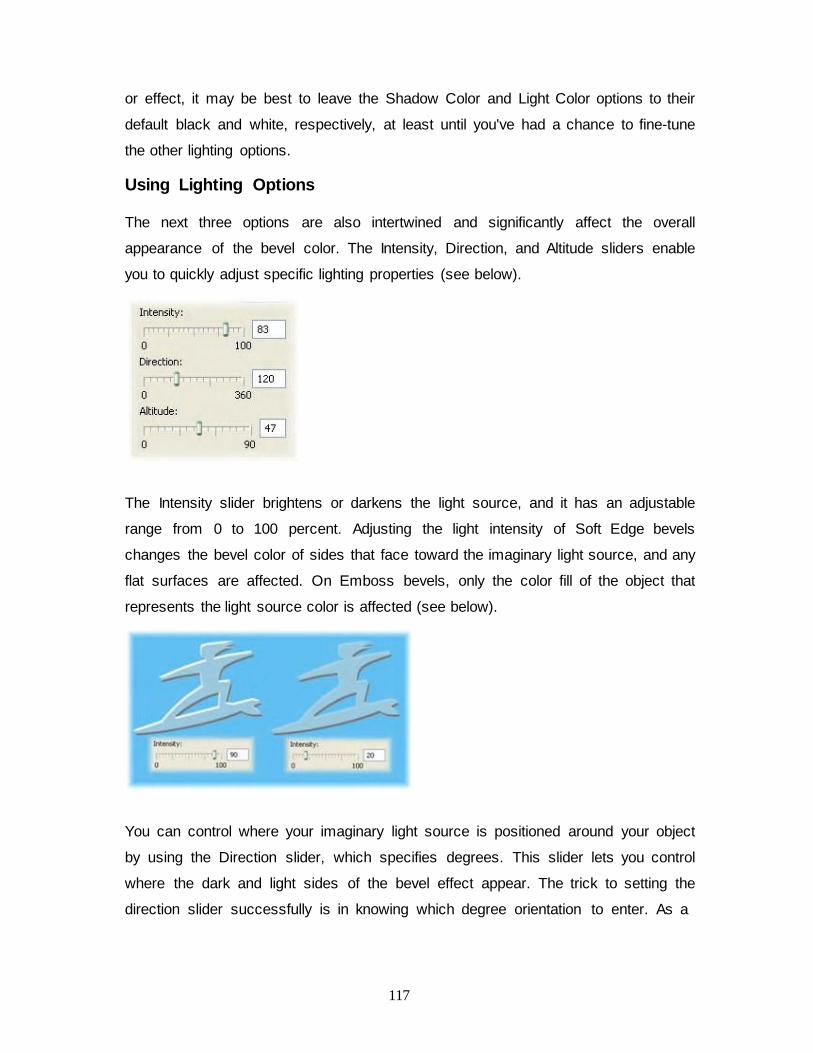
117
or effect, it may be best to leave the Shadow Color and Light Color options to their
default black and white, respectively, at least until you've had a chance to fine-tune
the other lighting options.
Using Lighting Options
The next three options are also intertwined and significantly affect the overall
appearance of the bevel color. The Intensity, Direction, and Altitude sliders enable
you to quickly adjust specific lighting properties (see below).
The Intensity slider brightens or darkens the light source, and it has an adjustable
range from 0 to 100 percent. Adjusting the light intensity of Soft Edge bevels
changes the bevel color of sides that face toward the imaginary light source, and any
flat surfaces are affected. On Emboss bevels, only the color fill of the object that
represents the light source color is affected (see below).
You can control where your imaginary light source is positioned around your object
by using the Direction slider, which specifies degrees. This slider lets you control
where the dark and light sides of the bevel effect appear. The trick to setting the
direction slider successfully is in knowing which degree orientation to enter. As a
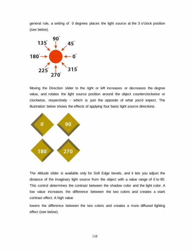
118
general rule, a setting of 0 degrees places the light source at the 3 o'clock position
(see below).
Moving the Direction slider to the right or left increases or decreases the degree
value, and rotates the light source position around the object counterclockwise or
clockwise, respectively - which is just the opposite of what you'd expect. The
illustration below shows the effects of applying four basic light source directions.
The Altitude slider is available only for Soft Edge bevels, and it lets you adjust the
distance of the imaginary light source from the object with a value range of 0 to 90.
This control determines the contrast between the shadow color and the light color. A
low value increases the difference between the two colors and creates a stark
contrast effect. A high value
lowers the difference between the two colors and creates a more diffused lighting
effect (see below).
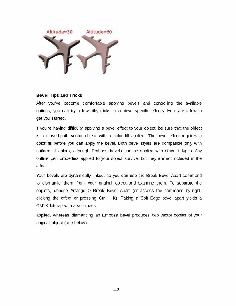
119
Bevel Tips and Tricks
After you've become comfortable applying bevels and controlling the available
options, you can try a few nifty tricks to achieve specific effects. Here are a few to
get you started.
If you're having difficulty applying a bevel effect to your object, be sure that the object
is a closed-path vector object with a color fill applied. The bevel effect requires a
color fill before you can apply the bevel. Both bevel styles are compatible only with
uniform fill colors, although Emboss bevels can be applied with other fill types. Any
outline pen properties applied to your object survive, but they are not included in the
effect.
Your bevels are dynamically linked, so you can use the Break Bevel Apart command
to dismantle them from your original object and examine them. To separate the
objects, choose Arrange > Break Bevel Apart (or access the command by right-
clicking the effect or pressing Ctrl + K). Taking a Soft Edge bevel apart yields a
CMYK bitmap with a soft mask
applied, whereas dismantling an Emboss bevel produces two vector copies of your
original object (see below).
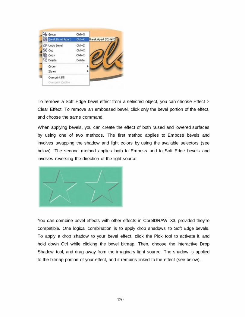
120
To remove a Soft Edge bevel effect from a selected object, you can choose Effect >
Clear Effect. To remove an embossed bevel, click only the bevel portion of the effect,
and choose the same command.
When applying bevels, you can create the effect of both raised and lowered surfaces
by using one of two methods. The first method applies to Emboss bevels and
involves swapping the shadow and light colors by using the available selectors (see
below). The second method applies both to Emboss and to Soft Edge bevels and
involves reversing the direction of the light source.
You can combine bevel effects with other effects in CorelDRAW X3, provided they're
compatible. One logical combination is to apply drop shadows to Soft Edge bevels.
To apply a drop shadow to your bevel effect, click the Pick tool to activate it, and
hold down Ctrl while clicking the bevel bitmap. Then, choose the Interactive Drop
Shadow tool, and drag away from the imaginary light source. The shadow is applied
to the bitmap portion of your effect, and it remains linked to the effect (see below).

121
The new bevel effect is a welcome addition to the arsenal of creative effects in
CorelDRAW X3. The effect can be applied quickly, requires no steep learning curve,
and is relatively uncomplicated to use. Being able to control the depth, color, and
lighting of your bevels allows you to produce truly customized results.
Shortcuts
Shortcuts Commands

122
B Align Bottom
E Align Centers Horizontally
C Align Center Vertically
L Align Left
R Align Right
Alt+F12 Align to Baseline
T Align Top
I Artistic Media
Ctrl+PageUp Back One
Ctrl+K Break Apart
Ctrl+B Brightness/Contrast/Intensity.. .
Ctrl+Enter Bring Up Property Bar
P Center to Page
Ctrl+T Character Formatting
Shft+F11 Color
Shift+F12 Color
Ctrl+Shft+B Color Balance...
Ctrl+L Combine
Ctrl+F9 Contour
Ctrl+F8 Convert
Ctrl+Shft+Q Convert Outline To Object
Ctrl+Q Convert to Curves
Ctrl+C Copy
Ctrl+Insert Copy
Ctrl+X Cut
Shft+Delete Cut Delete Delete
Shft+B Distribute Bottom
Shft+E Distribute Centers Horizontally
Shft+C Distribute Centers Vertically
Shft+L Distribute Left
Shft+R Distribute Right
Shft+P Distribute Spacing
Horizontally Shft+A Distribute Spacing Vertically
Shft+T Distribute Top
SHORTCUTS COMMANDS
Ctrl+D Duplicate
Alt+Shft+D Dynamic Guides
Ctrl+Shft+T Edit Text...
F7 Ellipse
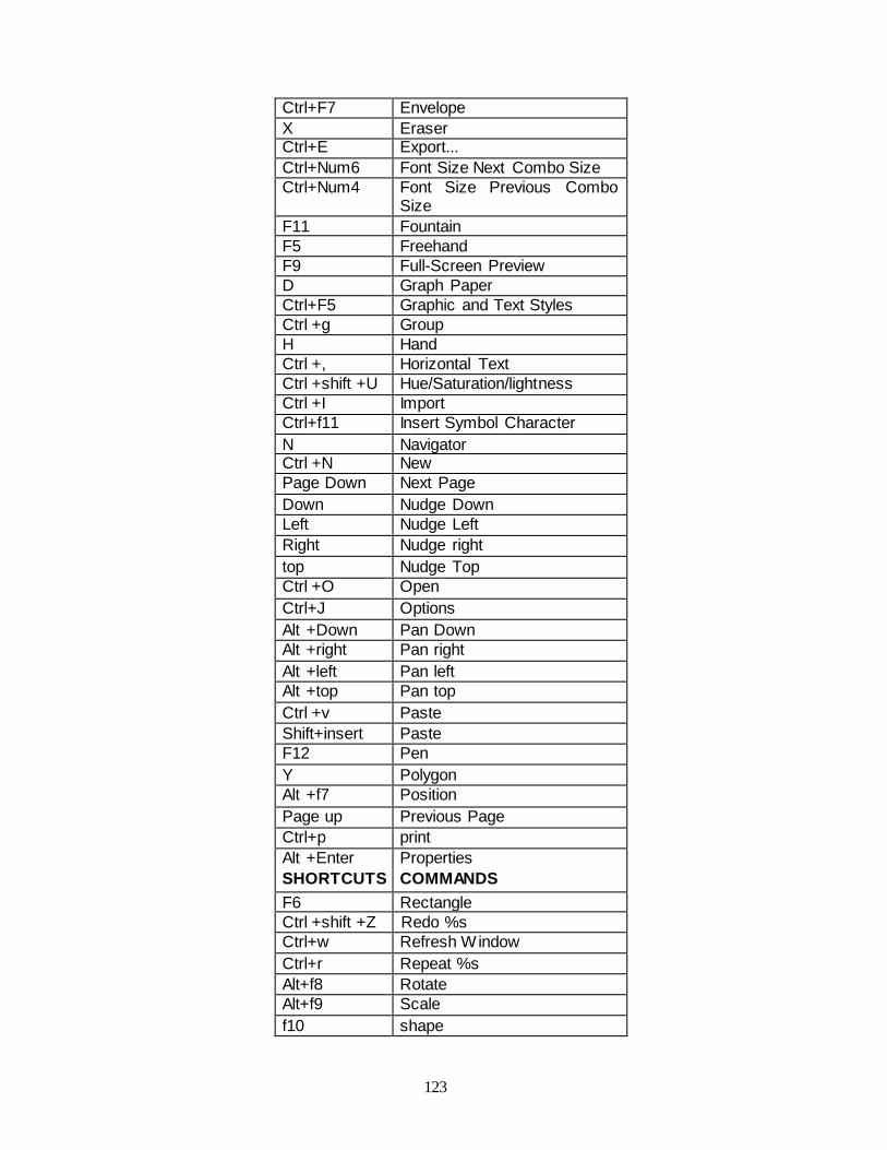
123
Ctrl+F7 Envelope
X Eraser Ctrl+E Export...
Ctrl+Num6 Font Size Next Combo Size
Ctrl+Num4 Font Size Previous Combo Size
F11 Fountain
F5 Freehand
F9 Full-Screen Preview
D Graph Paper
Ctrl+F5 Graphic and Text Styles
Ctrl +g Group
H Hand
Ctrl +, Horizontal Text
Ctrl +shift +U Hue/Saturation/lightness
Ctrl +I Import
Ctrl+f11 Insert Symbol Character
N Navigator Ctrl +N New
Page Down Next Page
Down Nudge Down
Left Nudge Left
Right Nudge right
top Nudge Top
Ctrl +O Open
Ctrl+J Options
Alt +Down Pan Down
Alt +right Pan right
Alt +left Pan left
Alt +top Pan top
Ctrl +v Paste
Shift+insert Paste
F12 Pen
Y Polygon
Alt +f7 Position
Page up Previous Page
Ctrl+p print
Alt +Enter Properties
SHORTCUTS COMMANDS
F6 Rectangle
Ctrl +shift +Z Redo %s
Ctrl+w Refresh Window
Ctrl+r Repeat %s
Alt+f8 Rotate
Alt+f9 Scale
f10 shape

124
Zlt+F10 Size
Shft+S Smart Drawing
Ctrl+Y Snap to Grid
Alt+Z Snap to Objects
Ctrl+F12 Spell Check...
A Spiral
Ctrl+Shft+D Step and Repeat...
Shft+Down Super Nudge Down
Shft+Left Super Nudge Left
Shft+Right Super Nudge Right
Shft+Up Super Nudge Up
Ctrl+F3 Refresh Window
Ctrl+r Symbol Manager
Shft+PageDo
wn
To Back of Layer
Ctrl+End To Back of Page
Shft+PageUp To Front of Layer
Ctrl+Home To Front of Page
Ctrl+Space Toggle Pick State
Shft+F9 Toggle View
Ctrl+Z Undo %s
Alt+Backspace Undo %s
Ctrl+U Ungroup
Ctrl+M Use Bullets
Ctrl+. Vertical Text
Ctrl+F2 View Manager
Alt+F11 Visual Basic Editor ...
Z Zoom
F2 Zoom One-Shot
F3 Zoom Out
F4 Zoom to Fit
Shft+F4 Zoom to Page
Shft+F2 Zoom to Selection


![Corel draw [mongol]](https://img.pdfslide.us/doc/110x75/55ac067c1a28ab9b518b4742/corel-draw-mongol.jpg)