Embed Size (px)
DESCRIPTION
Cordless Systems and Wireless Local Loop. Chapter 11. Cordless System Operating Environments. Residential – a single base station can provide in-house voice and data support Office A single base station can support a small office - PowerPoint PPT Presentation
Citation preview
Cordless Systems and Wireless Local Loop
Chapter 11
Cordless System Operating Environments Residential – a single base station can
provide in-house voice and data support Office
A single base station can support a small office Multiple base stations in a cellular
configuration can support a larger office Telepoint – a base station set up in a public
place, such as an airport
Design Considerations for Cordless Standards Modest range of handset from base station,
so low-power designs are used Inexpensive handset and base station,
dictating simple technical approaches Frequency flexibility is limited, so the
system needs to be able to seek a low-interference channel whenever used
Time Division Duplex (TDD) TDD also known as time-compression
multiplexing (TCM) Data transmitted in one direction at a time,
with transmission between the two directions Simple TDD TDMA TDD

Simple TDD Bit stream is divided into equal segments,
compressed in time to a higher transmission rate, and transmitted in bursts
Effective bits transmitted per second:
R = B/2(Tp+Tb+Tg)
R = effective data rate B = size of block in bits Tp = propagation delay Tb = burst transmission time Tg = guard time
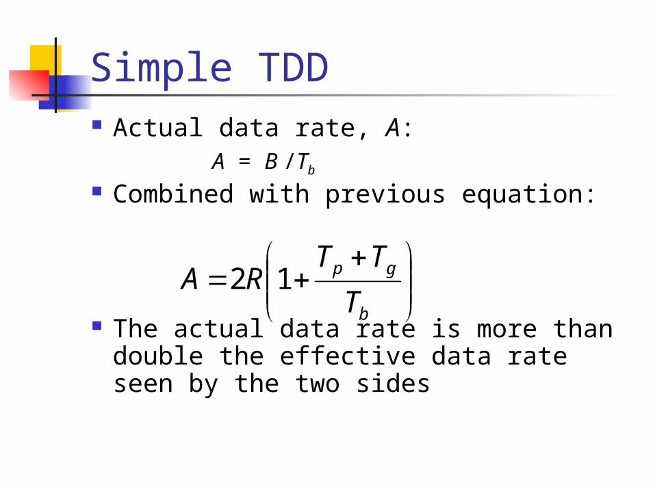
Simple TDD Actual data rate, A:
A = B /Tb
Combined with previous equation:
The actual data rate is more than double the effective data rate seen by the two sides
b
gp
T
TTRA 12
TDMA TDD Wireless TDD typically used with TDMA
A number of users receive forward channel signals in turn and then transmit reverse channel signals in turn, all on same carrier frequency
Advantages of TDMA/TDD: Improved ability to cope with fast fading Improved capacity allocation
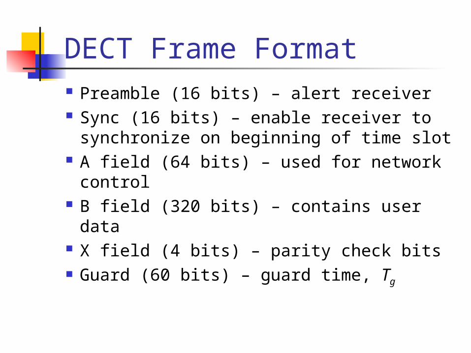
DECT Frame Format Preamble (16 bits) – alert receiver Sync (16 bits) – enable receiver to
synchronize on beginning of time slot A field (64 bits) – used for network control B field (320 bits) – contains user data X field (4 bits) – parity check bits Guard (60 bits) – guard time, Tg
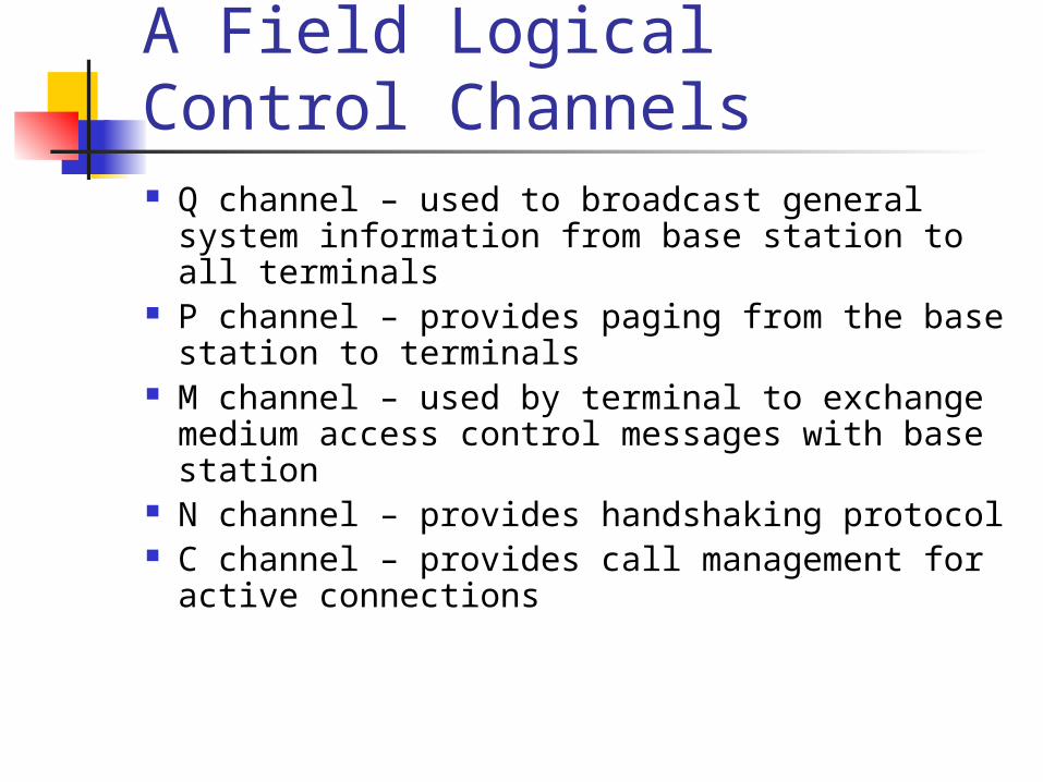
A Field Logical Control Channels Q channel – used to broadcast general system
information from base station to all terminals P channel – provides paging from the base station
to terminals M channel – used by terminal to exchange
medium access control messages with base station N channel – provides handshaking protocol C channel – provides call management for active
connections
B Field B field transmits data in two modes
Unprotected mode - used to transmit digitized voice
Protected mode - transmits nonvoice data traffic
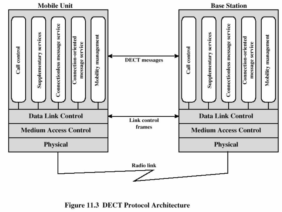
DECT Protocol Architecture
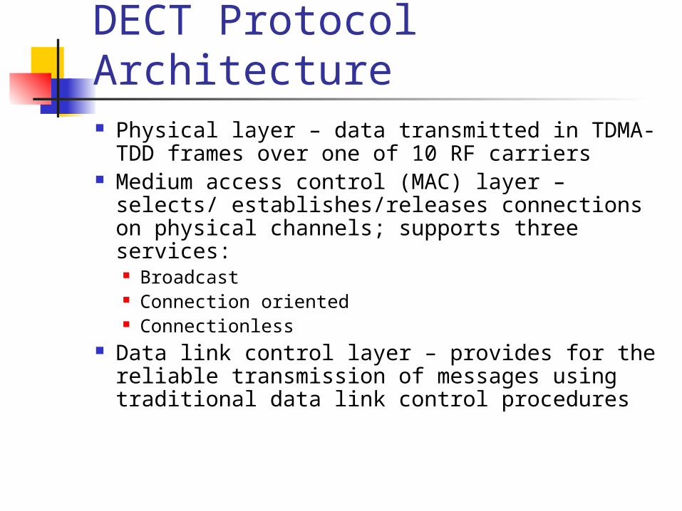
DECT Protocol Architecture Physical layer – data transmitted in TDMA-TDD
frames over one of 10 RF carriers Medium access control (MAC) layer – selects/
establishes/releases connections on physical channels; supports three services: Broadcast Connection oriented Connectionless
Data link control layer – provides for the reliable transmission of messages using traditional data link control procedures
Differential Quantization Speech signals tend not to change much between
two samples Transmitted PCM values contain considerable
redundancy Transmit difference value between adjacent samples
rather than actual value If difference value between two samples exceeds
transmitted bits, receiver output will drift from the true value Encoder could replicate receiver output and additionally
transmit that difference
Differential PCM (DPCM) Since voice signals change relatively slowly, value
of kth sample can be estimated by preceding samples
Transmit difference between sample and estimated sample Difference value should be less than difference between
successive samples At the receiver, incoming difference value is
added to the estimate of the current sample Same estimation function is used
Adaptive Differential PCM (ADPCM) Improve DPCM performance using
adaptive prediction and quantization Predictor and difference quantizer adapt to the
changing characteristics of the speech Modules
Adaptive quantizer Inverse adaptive quantizer Adaptive predictor

ADPCM Encoder

ADPCM Decoder
Subject Measurement of Coder Performance Subjective measurements of quality are
more relevant than objective measures Mean opinion score (MOS) – group of
subjects listen to a sample of coded speech; classify output on a 5-point scale
MOS scale is used in a number of specifications as a standard for quality
Wireless Local Loop Wired technologies responding to need for reliable,
high-speed access by residential, business, and government subscribers ISDN, xDSL, cable modems
Increasing interest shown in competing wireless technologies for subscriber access
Wireless local loop (WLL) Narrowband – offers a replacement for existing telephony
services Broadband – provides high-speed two-way voice and data
service
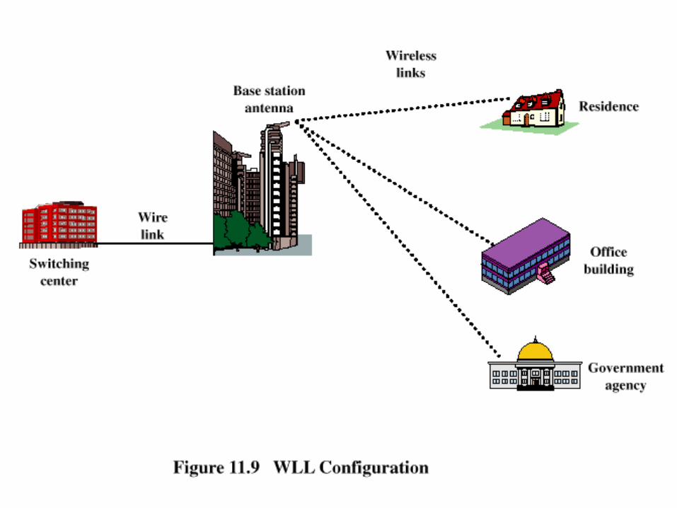
WLL Configuration
Advantages of WLL over Wired Approach Cost – wireless systems are less expensive due to
cost of cable installation that’s avoided Installation time – WLL systems can be installed
in a small fraction of the time required for a new wired system
Selective installation – radio units installed for subscribers who want service at a given time With a wired system, cable is laid out in anticipation of
serving every subscriber in a given area
Propagation Considerations for WLL Most high-speed WLL schemes use millimeter
wave frequencies (10 GHz to about 300 GHz) There are wide unused frequency bands available above
25 GHz At these high frequencies, wide channel bandwidths
can be used, providing high data rates Small size transceivers and adaptive antenna arrays can
be used
Propagation Considerations for WLL Millimeter wave systems have some
undesirable propagation characteristics Free space loss increases with the square of the
frequency; losses are much higher in millimeter wave range
Above 10 GHz, attenuation effects due to rainfall and atmospheric or gaseous absorption are large
Multipath losses can be quite high
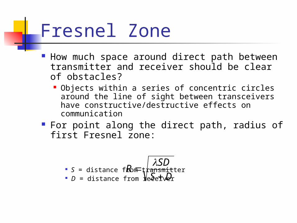
Fresnel Zone How much space around direct path between
transmitter and receiver should be clear of obstacles? Objects within a series of concentric circles around the line
of sight between transceivers have constructive/destructive effects on communication
For point along the direct path, radius of first Fresnel zone:
S = distance from transmitter D = distance from receiver DS
SDR
Atmospheric Absorption Radio waves at frequencies above 10 GHz
are subject to molecular absorption Peak of water vapor absorption at 22 GHz Peak of oxygen absorption near 60 GHz
Favorable windows for communication: From 28 GHz to 42 GHz From 75 GHz to 95 GHz
Effect of Rain Attenuation due to rain
Presence of raindrops can severely degrade the reliability and performance of communication links
The effect of rain depends on drop shape, drop size, rain rate, and frequency
Estimated attenuation due to rain:
A = attenuation (dB/km) R = rain rate (mm/hr) a and b depend on drop sizes and frequency
baRA
Effects of Vegetation Trees near subscriber sites can lead to multipath
fading Multipath effects from the tree canopy are
diffraction and scattering Measurements in orchards found considerable
attenuation values when the foliage is within 60% of the first Fresnel zone
Multipath effects highly variable due to wind
Multipoint Distribution Service (MDS) Multichannel multipoint distribution service
(MMDS) Also referred to as wireless cable Used mainly by residential subscribers and small
businesses Local multipoint distribution service (LMDS)
Appeals to larger companies with greater bandwidth demands
Advantages of MMDS MMDS signals have larger wavelengths and
can travel farther without losing significant power
Equipment at lower frequencies is less expensive
MMDS signals don't get blocked as easily by objects and are less susceptible to rain absorption
Advantages of LMDS Relatively high data rates Capable of providing video, telephony, and
data Relatively low cost in comparison with
cable alternatives
802.16 Standards Development Use wireless links with microwave or millimeter
wave radios Use licensed spectrum Are metropolitan in scale Provide public network service to fee-paying
customers Use point-to-multipoint architecture with
stationary rooftop or tower-mounted antennas
802.16 Standards Development Provide efficient transport of heterogeneous traffic
supporting quality of service (QoS) Use wireless links with microwave or millimeter
wave radios Are capable of broadband transmissions (>2
Mbps)
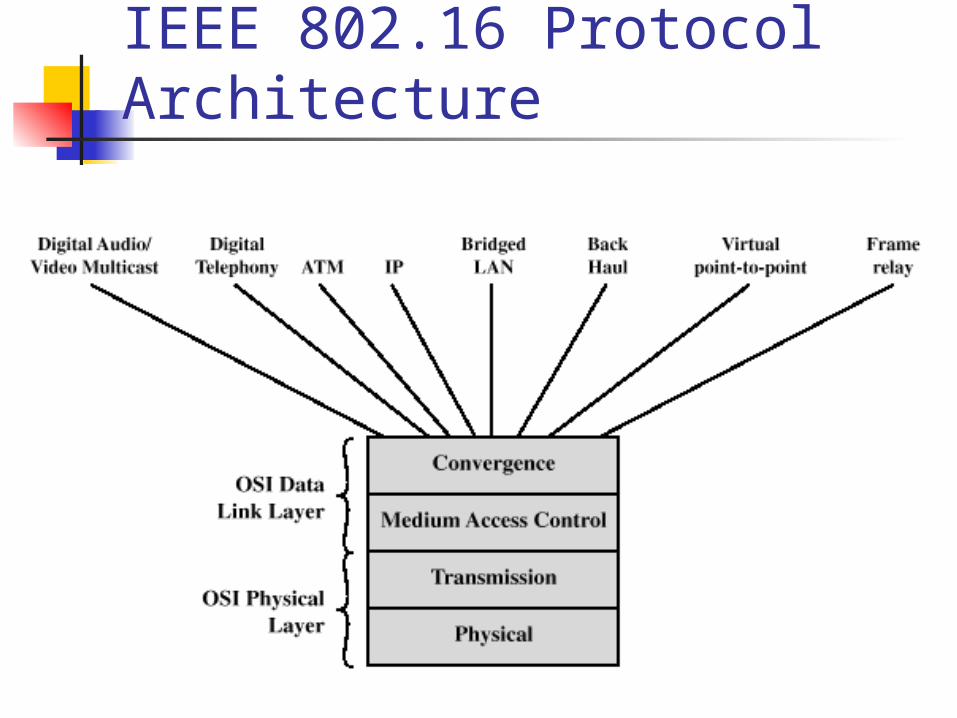
IEEE 802.16 Protocol Architecture

Protocol Architecture Physical and transmission layer functions:
Encoding/decoding of signals Preamble generation/removal Bit transmission/reception
Medium access control layer functions: On transmission, assemble data into a frame with
address and error detection fields On reception, disassemble frame, and perform address
recognition and error detection Govern access to the wireless transmission medium
Protocol Architecture Convergence layer functions:
Encapsulate PDU framing of upper layers into native 802.16 MAC/PHY frames
Map upper layer’s addresses into 802.16 addresses
Translate upper layer QoS parameters into native 802.16 MAC format
Adapt time dependencies of upper layer traffic into equivalent MAC service
IEEE 802.16.1 Services Digital audio/video multicast Digital telephony ATM Internet protocol Bridged LAN Back-haul Frame relay

IEEE 802.16.3 Services Voice transport Data transport Bridged LAN
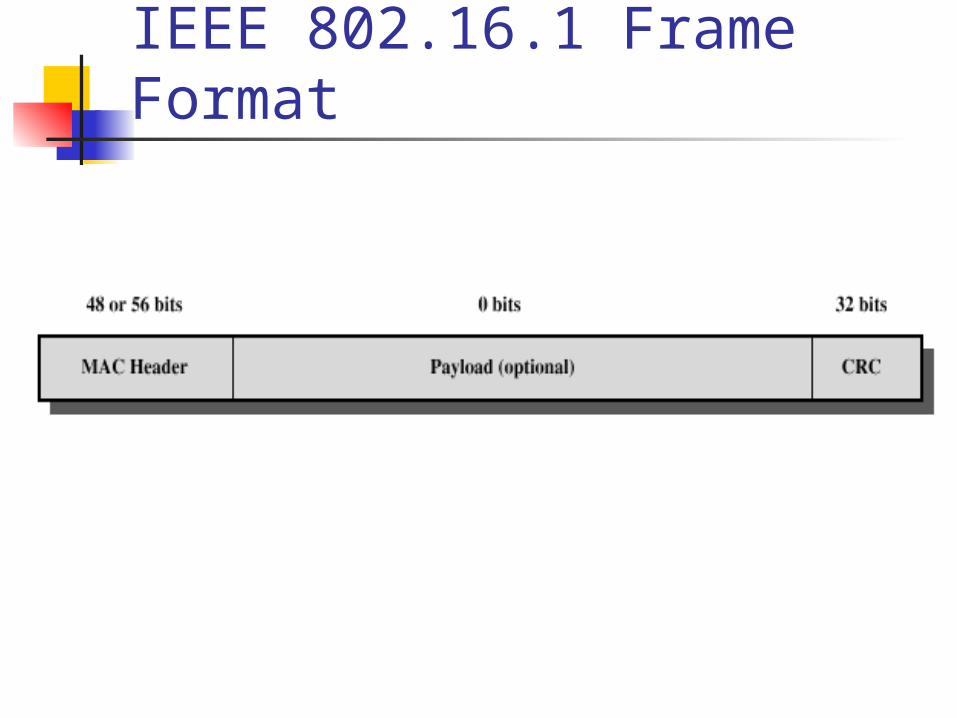
IEEE 802.16.1 Frame Format
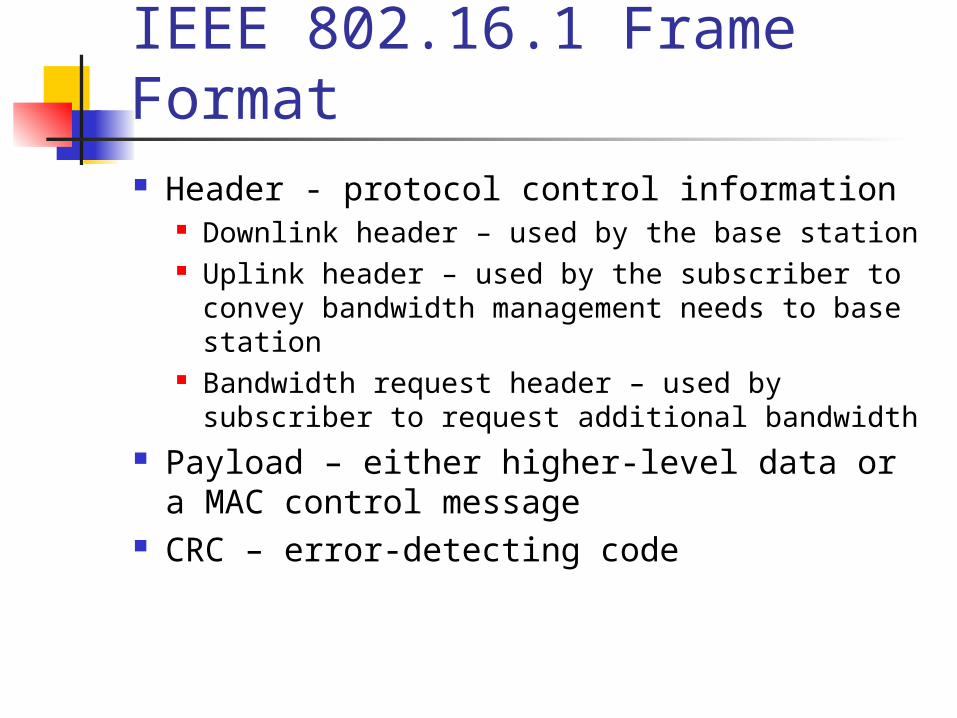
IEEE 802.16.1 Frame Format Header - protocol control information
Downlink header – used by the base station Uplink header – used by the subscriber to convey
bandwidth management needs to base station Bandwidth request header – used by subscriber to
request additional bandwidth Payload – either higher-level data or a MAC
control message CRC – error-detecting code
MAC Management Messages Uplink and downlink channel descriptor Uplink and downlink access definition Ranging request and response Registration request, response and acknowledge Privacy key management request and response Dynamic service addition request, response and
acknowledge
MAC Management Messages Dynamic service change request, response,
and acknowledge Dynamic service deletion request and
response Multicast polling assignment request and
response Downlink data grant type request ARQ acknowledgment
Physical Layer – Upstream Transmission Uses a DAMA-TDMA technique Error correction uses Reed-Solomon code Modulation scheme based on QPSK
Physical Layer – Downstream Transmission Continuous downstream mode
For continuous transmission stream (audio, video) Simple TDM scheme is used for channel access Duplexing technique is frequency division duplex (FDD)
Burst downstream mode Targets burst transmission stream (IP-based traffic) DAMA-TDMA scheme is used for channel access Duplexing techniques are FDD with adaptive modulation,
frequency shift division duplexing (FSDD), time division duplexing (TDD)