Embed Size (px)
Citation preview

Copyright Warning & Restrictions
The copyright law of the United States (Title 17, United States Code) governs the making of photocopies or other
reproductions of copyrighted material.
Under certain conditions specified in the law, libraries and archives are authorized to furnish a photocopy or other
reproduction. One of these specified conditions is that the photocopy or reproduction is not to be “used for any
purpose other than private study, scholarship, or research.” If a, user makes a request for, or later uses, a photocopy or reproduction for purposes in excess of “fair use” that user
may be liable for copyright infringement,
This institution reserves the right to refuse to accept a copying order if, in its judgment, fulfillment of the order
would involve violation of copyright law.
Please Note: The author retains the copyright while the New Jersey Institute of Technology reserves the right to
distribute this thesis or dissertation
Printing note: If you do not wish to print this page, then select “Pages from: first page # to: last page #” on the print dialog screen

The Van Houten library has removed some of the personal information and all signatures from the approval page and biographical sketches of theses and dissertations in order to protect the identity of NJIT graduates and faculty.
ABSTRACT
INDIVIDUAL CELL PRESSURE CONTROL IN AIR MATTRESS FOR THEPREVENTION OF THE PRESSURE SORES
byKapilchandra Anand
Many kinds of pressure-relieving mattresses have been developed to prevent pressure
sores in patients with spinal cord injuries (SCIs) and obesity. Current technology uses
alternating air pressure mattress, foam and low pressure mattress for reducing the
incidence of pressure sores in SCI and obesity patients. These mattresses do not have
control of pressure in individual air chambers. They are open loop system and they do not
receive any feedback from the system. They have at the most control of two different
pressures. The purpose of this study is to improve the current assistive technology in
reducing pressure sores and to distribute the patient's weight evenly on the air mattress
by setting the appropriate pressure in each individual chamber.
The proposed mattress has an independent control of each and every chamber,
flexibility in selecting firmness and range, number of chambers to be operated at a time
and mode of operation. It is a closed loop system and hence, it can respond to the change
in pressure inside the system to keep it stable. National Instruments (NI) software
LabVIEW® 8 is used for this purpose. The proposed mattress has an accuracy of
approximately 98% and reliability of approximately 96%. Correct operation of the
feedback control system to maintain cell pressure in the specified ranges during patient
movement was validated with a small pilot study. A patient experiment is proposed to
compare this mattress with current available mattresses in the market. It is hypothesized
that individual cell pressure control mattress is better than alternating pressure mattress.
INDIVIDUAL CELL PRESSURE CONTROL IN AN AIR MATTRESS FOR THEPRVENTION OF THE PRESSURE SORES
byKapilchandra Anand
A ThesisSubmitted to the Faculty of
New Jersey Institute of Technologyin Partial Fulfillment of the Requirements for the Degree of
Master of Science in Biomedical Engineering
Department of Biomedical Engineering
August 2006


APPROVAL PAGE
INDIVIDUAL CELL PRESSURE CONTROL IN AN AIR MATTRESS FOR THEPREVENTION OF THE PRESSURE SORES
Kapilchandra Anand
Dr. Tara Alvarez Thesis Advisor DateAssociate Professor of Biomedical Engineering, NJIT
Michael T. Bergen, Thesis Co-Advisor DateVeterans Affairs New Jersey Health Care System, East Orange, NJAdjunct Professor of Biomedical Engineering Technology, NJIT
Dr. Sergei Adamovich, Committee Member DateAssociate Professor of Biomedical Engineering, NJIT
D1. Lisa K. Simone, Committee Member DateAssistant Research Professor of Biomedical Engineering, NJIT

BIOGRAPHICAL SKETCH
Author: Kapilchandra Anand
Degree: Master of Science
Date: August 2006
Undergraduate and Graduate Education:
• Master of Science in Biomedical Engineering,New Jersey Institute of Technology, Newark, NJ, 2006
• Bachelor of Engineering in Mechatronics Engineering,Shri U. V. Patel College of Engineering, Ahmedabad, India, 2003
Major: Biomedical Engineering
iv

To my parents, Ramanlal Makwana and Nandaben Makwana and my family
for their support through out whole thesis tenure
v

ACKNOWLEDGMENT
I would like to thank Professor Michael Bergen, my advisor, who has guided me
throughout my thesis tenure with his comprehensive knowledge in biomedical science
and has always motivated me. His valuable and countless resources, insights and support
played a major part towards the completion of my thesis.
I would also like to thank Dr. Tara Alvarez, who guided me towards the
completion of my thesis. She also helped me with my graduate studies.
Special thanks are given to Dr. Sergei Adamovich and Dr. Lisa Simone for their
active participation in my thesis committee and for their valuable suggestions.
Thanks to Gladstone Reid for his support and motivation throughout my thesis
and also thanks to all the other members of the Neurobehavioral Research Unit at the
Veteran Affairs New Jersey Health Care System, East Orange.
Besides all the above people, I always had my parents, my sisters and brother with
me to motivate and encourage me in completion of my thesis. They always made me
laugh in my bad times and always helped me to come out of all odds. Thanks to my
friend, Shaifali for her motivation and support throughout my thesis. Thanks to all my
friends for their endless support.
vi
TABLE OF CONTENTS
Chapter Page
1 INTRODUCTION 1
1.1 Objective 1
1.2 Background 2
1.2.1 Spinal Cord Injury 2
1.2.2 Obesity 5
1.2.3 Pressure Sores 6
1.3 Current Assistive Technology. 9
2 INSTRUMENTATION 12
2.1 Air Mattress 13
2.2 Control Valves 17
2.3 Pressure Sensor 18
2.4 Voltage (Offset) Subtraction Circuit 20
2.5 Data Acquisition 22
3 CONTROL LOGIC 27
3.1 Software Logic 27
3.2 Software Controlled Features 32
4 VERIFICATION, RELAIABILTY AND SAFETY OF THE SYSTEM 33
4.1 Verification of the system 33
4.1.1 Accuracy Test 33
4.1.2 Repeatability Test 34
vii

TABLE OF CONTENTS(Continued)
Chapter Page
4.1.3 Validation of the System Feedback 36
4.2 Reliability and Safety of the System 42
5 EXPERIMENTATION 45
5.1 Identifying Population for the Application of the Methods 45
5.2 Types of Pressure Relieving Interventions 48
5.3 Evaluating Pressure Relieving Interventions. 49
5.3.1 Data Collection and Data Synthesis 51
5.4 Proposed experiment 51
6 HYPOTHESIZED RESULTS AND DISCUSSIONS 55
6.1 Results from Comparative Studies of the Three Pressure Relieving Surfaces.... 55
6.1.1 Results from Comparison Between Alternating Pressure Mattress andStandard Mattress 55
6.1.2 Results from Comparison Between Alternating Pressure Mattress andConstant Low Pressure Mattress 56
6.1.3 Results from Comparison Between AB Mode Alternating PressureMattress and ABCDE Mode Alternating Pressure Mattress 59
6.2 Discussion 60
7 CONCLUSION 63
8 FUTURE DEVELOPMENTS 64
APPENDIX A SPECIFICATIONS AND FEATURES OF THE AIR MATTRESS 65
APPENDIX B SPECIFICATIONS OF THE PRESSURE SENSOR MPX5100AP 67
APPENDIX C SPECIFICATIONS OF NI DAQ PCI 6024E CARD 69
viii
TABLE OF CONTENTS(Continued)
Chapter Page
APPENDIX D PIN ASSISGNMENT PC DIO 96 DIGITAL I/O CONNECTOR 75
APPENDIX E SPECIFICATIONS AND CAD DRAWING OF CONTROL VALVE. 76
APPENDIX F SPECIFICATIONS OF LM324 OP-AMP 78
APPENDIX G FRONT PANEL OF THE LABVIEW CODE 80
APPENDIX H BLOCK DIAGRAM OF THE LABVIEW CODE 82
REFERENCES 84
ix

LIST OF TABLES
Table Page
2.1 Correspondence Between Pressure and Output from the Pressure Sensor.... 22
3.1 Allocation of Digital Ports and Digital Lines to the Control Valve of the AirMattress 31
4.1 Results of the Accuracy Test When the Mattress is Operating in ABCDE Modeand Soft Firmness Level 34
4.2 Results of the Accuracy Test When the System is Operated in ABCDE Modeand Firm Firmness Level 34
4.3 Results of the Repeatability Test of the System 35
4.4 Pressure Sensor Output for Cell 1 and Cell 2 38
4.5 Pressure Sensor Output for Short Period Impulse Force 41
5.1 Norton Pressure Sore Prediction Score 46
5.2 Studies of the Predictive Validity of Risk Assessment Tools 47
5.3 Mechanism of ABCDE Alternating Pressure Mattress 52
5.4 Distribution of Patients for the Experiment 54
6.1 Results from the Comparison between AP Mattress and Standard Mattress,when Incidence of Pressure Sores of Grade II or Greater is Considered as aMeasure of Outcome 56
6.2 Results from the Comparison between AP Mattress and CLP Mattress, whenIncidence of Pressure Sores of Grade II or Greater is Considered as a Measureof Outcome.... 57
6.3 Results from the Comparison between AP Mattress and CLP Mattress, whenIncidence of Pressure Sores of any Grade is Considered as a Measure ofOutcome 58
E.1 Specification of Control Valve 77
x

LIST OF FIGURES
Figure Page
1.1 Effects of spinal cord injury 4
1.2 Areas of high risk of pressure sores 6
1.3 Different stages of pressure sores 7
1.4 Alternating air pressure mattress 10
2.1 Block diagram of the air mattress system 13
2.2 Hose connections of the first three cell of the air 13
2.3 Stimulus plus alternating pressure mattress 14
2.4 Control unit of stimulus plus alternating pressure mattress 15
2.5 Modified connections of the air mattress 16
2.6 Block diagram showing connections of the system.... 16
2.7 2-way directional control valve.... 17
2.8 Fully integrated pressure sensor schematic 18
2.9 Cross sectional diagram of the pressure sensor 19
2.10 Output versus pressure differential 20
2.11 Voltage offset removal circuit 21
2.12 NI DAQ PCI 6024E Card 23
2.13 NI DAQ PCI DIO 96 Card 24
2.14 CB-50LB connection block and ribbon cable 25
3.1 Flow diagram of the individual cell pressure control air mattress 28
3.2 Block diagram of the selection of mode and firmness level of the mattress 29
4.1 Pressure sensor output for cell 1 and cell 2 due to patient movement 39
xi

LIST OF FIGURES(Continued)
Figure Page
4.2 Feedback for cell 1 and cell 2 due to patient movement 40
4.3 Pressure change and system feedback for a short period impulse force 42
5.1 Mechanism of action of alternating pressure mattress 49
E.1 CAD diagram of control valve 76
xii
CHAPTER 1
INTRODUCTION
1.1 Objective
It is estimated that the incidence of spinal cord injury in US is approximately 11,000 new
cases annually. According to a study conducted in 1970, the number of people in the
United States in July 2005, who have spinal cord injury (SCI), was estimated
approximately to 250,000 persons [1]. Majority of the spinal cord injury patients have
limited mobility and many of them are even unable to get up from the bed for a long
period, which causes pressure sores at their back portion of the body. At any given time,
an estimated 17% to 39% of the SCI population suffers from pressure sores [19].
The goal of this thesis is to present a better and more precise control of the
pressure in the air mattress and hence, to present a better way to prevent and reduce the
incidence of pressure sores in the SCI patients. This thesis presents the development of
hardware circuit and a LabVIEW program to control pressure in the individual air
chamber of the mattress (Model Stimulus Plus, Recover Care, Plymouth Meeting, PA)
and thereby provide a better comfort and blood circulation to the patient.
Current assistive technologies for prevention and treatment of pressure sores in
these patients use an alternating pressure, foam, air, gel and water mattresses which does
not have control of pressure in individual air chambers. Currently, the most sophisticated
mattress is alternating pressure mattresses in which each alternate air chamber has equal
pressure and the chambers inflate and deflate in an alternate fashion. These mattresses do
1
2
not have a feedback system and therefore, they are not able to respond to the change in
pressure caused due to the patient's movement or change of posture.
The proposed mattress has an independent control of each and every chamber,
flexibility in selecting firmness and range, number of chambers to be operated at a time
and mode of operation. It is a closed loop system and hence, has can respond to the
change in pressure inside the system to keep stable. LabVIEW programming, electronic
and pneumatic circuits are used to achieve this goal.
1.2 Background
1.2.1 Spinal Cord Injury
The spinal cord is the main pathway of communication between the brain and the rest of
the body. It extends from the base of the brain to the coccyx or the tail bone. The nerves
within the spinal cord are upper motor neurons and their function is to carry the messages
back and forth from the brain along the spinal tract to the spinal nerves. The spinal nerves
called lower motor neurons; branch out from the spinal cord to the other parts of the
body. Each spinal nerve has two nerve roots, motor root in the front and sensory root in
the back (except the first, which has no sensory root). The motor root transmits impulses
from the spinal cord to the muscles and stimulates movement and the sensory root carries
sensory information like pain, touch and temperature from the body to the spinal cord.
The motor nerves are grouped together and also the sensory nerves. The motor and
sensory nerves of the spinal cord connect with the motor and sensory roots of the spinal
nerves, respectively. The brain and the spinal cord constitute the Central Nervous System
[2].

3
The spinal cord is protected by the vertebrae of the spine (spinal column), which
are separated and protected by disks made of cartilage. The spine is divided into four
areas: cervical (neck), thoracic (chest), lumbar (lower back), and sacral (pelvis). Each
area is referred to by a letter (C, T, L, or S). The vertebrae in each area of the spine are
numbered beginning at the top. For example, the first vertebra in the cervical spine is
labeled C 1, the second in the thoracic spine is T2, the fourth in the lumbar spine is IA,
and so forth [2]. The spinal cord is also divided into segments and named and numbered
from top to bottom. Each segment marks where spinal nerves emerge from the cord to
connect to specific regions of the body. Cervical spinal nerves (Cl to C8) control signals
to the back of the head, the neck and shoulders, the arms and hands, and the diaphragm.
Thoracic spinal nerves (T1 to T12) control signals to the chest muscles, some muscles of
the back, and parts of the abdomen. Lumbar spinal nerves (L1 to L5) control signals to
the lower parts of the abdomen and the back, the buttocks, some parts of the external
genital organs, and parts of the leg. Sacral spinal nerves (Si to S5) control signals to the
thighs and lower parts of the legs, the feet, most of the external genital organs, and the
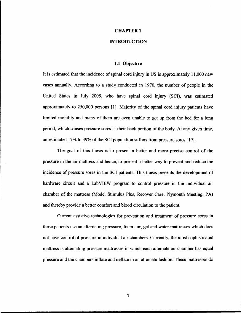
area around the anus [2]. The problems caused by the SCI at different locations of the
spine are shown in the Figure 1.1.
4
Figure 1.1 Effects of spinal cord injury [3] .
Spinal Cord Injury (SCI) occurs due to the damage caused to the spinal cord
which results in the loss of mobility and sensation. Common causes are trauma due to car
accident, falls, etc. or diseases such as polio, spina bifida, Friedreich's Ataxia, etc. [2][6].
Due to lack of mobility, SCI patients have to remain in bed for six months or longer.
5
Patients having severe SCI have greater immobility [4]. Pressure caused due to
lying or sitting at the same position for a long period restricts the blood flow and hence,
blocks the source of oxygen and nutrients to the skin tissues. When the tissue becomes
starved for a long period it begins to die and a pressure sore starts to form. Even people
with SCI lack feeling or mobility, often do not feel or are unable to respond to these
pressure pains and move to a new position further aggravate the pressure sores. Pressure
sores occurs mostly in paraplegic patients, the aged who have limited movement and
those who are anesthetized during long surgery [4].
1.2.2 Obesity
Obesity is a disease that affects nearly one-third of the adult American population
(approximately 60 million). The number of overweight and obese Americans has
continued to increase since 1960, and is not slowing down. In 2000, 64.5 percent of adult
Americans are categorized as being overweight and 30.5 percent as being obese. Severe
obesity prevalence is 4.7 percent [5].
Body mass index, expressed as weight/height 2 (BMI; kg/m2) is commonly used to
classify overweight and obesity among adults [6]. Overweight is defined as a BMI of 25
or more, obesity is 30 or more, and severe obesity is 40 or more [5]. Patients with
moderate obesity have little mobility due to overweight and when they lay down in bed
they can hardly turn or move their body from one posture to another and hence, they feel
constant pressure on their body. The portions of the body where high intensity pressure
remains for a longer period, starts developing pressure sores. Even though these patients
have sensing ability for pain due to pressure, they cannot move their body due to being
overweight.

6
1.2.3 Pressure Sores
Pressure sores can be the most devastating complication of SCI and moderate obesity
patients. Pressure sores are caused by prolonged pressure or rubbing on vulnerable areas
of the body that are prone to moisture and friction [6]. When a person remains in the
same position, blood flow is reduced from those areas, blocking oxygen and required
nutrients from maintaining healthy tissue. After a certain period of time, the tissue begins
to die and pressure sore start to form [7]. Normally the nerves send messages of pain or
feelings of discomfort to the brain to let patient know that he needs to change position,
but in SCI patients, the damaged spinal cord keeps these messages from reaching brain
due to which the patient loses sensitivity and further increasing the severity of pressure
sores [6].
JIro ...... -lnner knees
Back of head and ears
b ~ Shoulder Lower back and buttocks Heel
Figure 1.2 Areas of high risk of pressure sensor [8].
7
Pressure sores are also caused due to friction, bruises or scrapes, as well as
prolonged wetness on the skin [2]. The major symptoms of the pressure sores are redness
of the skin, pain and itching. Pressure sores occur most frequently over areas where bones
come close to the surface. The most common sites of pressure sores are the elbows, heels,
shoulders, hips, ankles, knees, buttocks [2] .
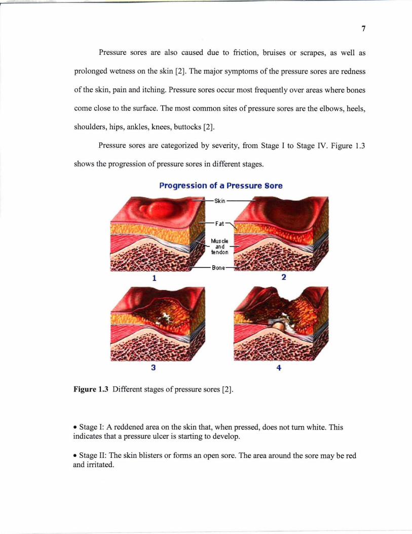
Pressure sores are categorized by severity, from Stage I to Stage IV. Figure 1.3
shows the progression of pressure sores in different stages.
Progression of a Pressure Sore
1 2
3 4
Figure 1.3 Different stages of pressure sores [2].
• Stage I: A reddened area on the skin that, when pressed, does not turn white. This indicates that a pressure ulcer is starting to develop .
• Stage II: The skin blisters or forms an open sore. The area around the sore may be red and irritated.
8
• Stage III: The skin breakdown now looks like a crater where there is damage to thetissue below the skin.
• Stage IV: The pressure ulcer has become so deep that there is damage to the muscle andbone, and sometimes tendons and joints [9].
As prevention is better than a cure, it is always better to take care of the
parameters which increase the risk of the onset of pressure sores. Pressure sores are easier
to prevent than to treat, but the process is complicated. Although wounds can develop in
spite of the most scrupulous care, it is possible to prevent them in many cases. Changing
patient position frequently and consistently is crucial to preventing pressure sores.
Experts advise shifting position every 15 to 30 minutes when the patient is in a
wheelchair and at least once every 2 hours, even during the night, even if the patient
spends most of his/her time in bed [10]. Soft support surfaces can be used in wheelchairs
and beds to reduce pressure. Patient's skin should be kept clean and dry to avoid wetness
due to patient's urine and drugs. Lubricating creams should be used for patients having
dry skin. Patients should have enough intake of fluid to keep the skin well hydrated.
Patient should be provided with a well balanced diet. Foods high in protein, vitamins and
minerals help the skin to stay healthy and heal more quickly [10].
Once the pressure sores start to develop, immediate treatment is required to cure
them. Treatment of pressure sores is more challenging than preventing them. Pressure
sores at Stage I and Stage II can be treated using conservative steps but those at Stage III
and Stage IV sometimes require surgical treatment. Treatment of pressure sores includes
frequently turning and repositioning and use of soft support surfaces like foam, gel,
water, air mattresses depending upon the severity of the pressure sores and mobility of
the patient. Wounds must be kept clean to prevent infection. A Stage I wounds can be

9
gently washed with water, but open sores should be cleaned with saline water each time
the dressing is changed. Damaged tissues are removed from the wounds to provide proper
healing to the wounds. These tissues are either removed by surgical or non-surgical
method depending upon the severity of the wound. Dressing can be used to protect
wounds and speed healing. There are variety of dressings used depending upon the stage
and severity of the wounds. It helps in keeping the wound moist and the surrounding skin
dry. Contaminated wounds can be treated with topical antibiotic cream. Patient should be
given a healthy diet in adequate calories and proteins and proper range of vitamins and
minerals. Surgical methods are also used to improve hygiene and appearance of the sores,
preventing or treating infection and lowering the risk of future cancer [10].
1.3 Current Assistive Technology
Current assistive technology used to treat pressure sores in SCI patient are different types
of foam, gel, water or air beds or pads. The air mattresses usually used for prevention
and treatment of pressure sores are low pressure air mattresses, water mattress, gel
mattress, alternating pressure mattress and rotating pressure mattress. In these mattresses,
the pressure in the air chamber are controlled in a limited manner. Low air loss beds and
mattresses have air sacs that support the user on a cushion of air. They work by
increasing the surface area in contact with the skin, therefore reducing the pressure at a
particular point. Air is gradually lost and continually replaced in response to the weight
distribution and movement of the user [11]. Water and foam cushions are made of open
foam filled with water. The foam not only helps to add stability but also helps the cushion
to conform to the body shape. They are cold to sit on and can therefore reduce skin

10
temperature [II]. The most sophisticated mattress used for preventing or treating pressure
sores is the alternating pressure mattress. In alternating pressure mattresses, the air cells
are divided vertically into three sets. For example, in an air mattress of 18 air cells, the
first set consists of first three air cell which supports the head portion of the patient.
Second set consists of the alternate air cells from the remaining (i.e. , cells 5, 7, 9, II, 13,
IS). Third set consist of the other remaining alternate air cells (i.e. , cells 4, 6, 8, 10, 12,
14, 16).
Figure 1.4 Alternating Air Pressure Mattress.
The pressure in each alternate chamber in the same set remains the same at a time.
For example, set I has 40mmHg, set 2 has OmmHg and set 3 has 50mmHg. Therefore,
each air cell in each set has the same pressure. In rotational air mattresses, the cells are
divided both horizontally and vertically. It has sets of air cells. The first set has upper
cells for the head portion. The second and the third set have left and right side cells,
respectively. This kind of mattress is usually used to help the patient in turning right or

11
left. It is similar to alternating pressure mattress as left and right set of air cells inflate and
deflate in an alternate manner.
The current mattresses used for the prevention of pressure sores are open loop
systems. Therefore, they are not able to respond automatically to any change in pressure
inside the mattress. For example, if the patient in on the mattress and some external force
is applied to the mattress, then the pressure inside the chambers where an external force is
applied will increase. As the system does not receive any feedback, the pressure will
remain until the external force is removed. This will apply more pressure on the patient's
body and if the pressure remains for very long period than the risk of developing pressure
sores will increase. The current mattresses do not have flexibility in holding different
pressure inside different chamber. They do not have precise firmness range control. They
only have some fixed firmness levels such as soft, medium and firm. These mattresses
use a pressure range of 30mmHg to 90mmHg.
CHAPTER 2
INSTRUMENTATION
Many components are used in constructing an air mattress with individual control of
pressure in each cell of the air-chamber. The system for this research project consists of
air mattress, pneumatic pump, directional control valves and a software program to
control the system so that it can inflate and deflate the chamber according to the
requirements of the patient or medical staff. The control of air pressure in the individual
air chamber is controlled using a pneumatic directional control valves. A pressure sensor
is attached to each air chamber which gives feedback to the software program through the
data acquisition card NI PCI 6024E, National Instruments, Austin, TX. According to the
feedback, the software program will inflate or deflate the air chamber by opening or
closing the control valve of an air chamber.
Control of these valves is accomplished by providing a trigger from a software
program written in National Instruments (NI) software LabVIEW ® 8. The software
receives feedback from the NI DAQ PCI 6024E card through NI NBC-2090 connector
block interface and it provides output through a 96 port digital input/output card (NI
DAQ PCI DIO 96, National Instruments, Austin, TX). This whole system requires 32
digital outputs from the PCI DIO 96 card to trigger on/off state of the pneumatic valves.
This section will explore the role, constitution, advantages and limitations of these
components. The block diagram of the whole individual cell pressure mattress system is
shown in Figure 2.1.
12

13
- Pressure PCI6024E Sensor Card L.
LabVIEW Air f--. Program Mattress Inlet Pump -Cell Valve l+- i
PCI DIO 96 - Exhaust Card Valve
Figure 2.1 Block diagram of the air mattress system.
2.1 Air Mattress
The air mattress used in this system is an alternating pressure mattress (Model Stimulus
Plus, Recover Care, Plymouth Meeting, PA). In this mattress air chambers inflate and
deflate alternatively. It has 18 air chambers in total. The top three chambers are
interconnected to each other and they support the head of the patient. These top three
chambers are interconnected to each other and have the same pressures at a time.
Figure 2.2 shows the connection of these top three chambers.
Figure 2.2 Hose connections for the first three chambers of the air mattress.
14
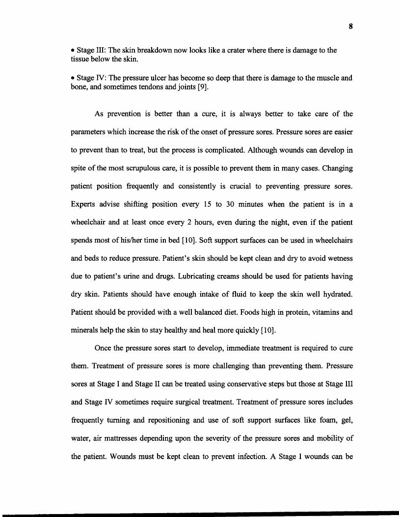
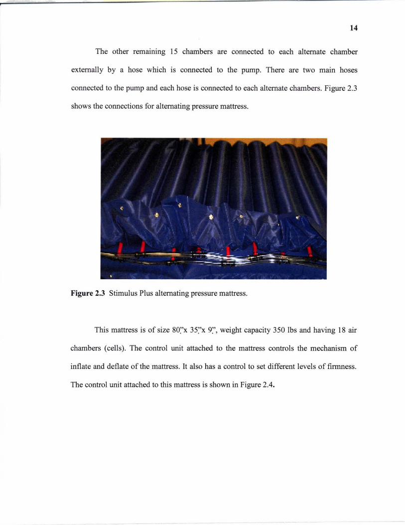
The other remammg 15 chambers are cormected to each alternate chamber
externally by a hose which IS cormected to the pump. There are two mam hoses
cormected to the pump and each hose is cormected to each alternate chambers. Figure 2.3
shows the cormections for alternating pressure mattress.
Figure 2.3 Stimulus Plus alternating pressure mattress.
This mattress is of size 80~'x 35~'x 9~', weight capacity 350 Ibs and having 18 air
chambers (cells). The control unit attached to the mattress controls the mechanism of
inflate and deflate of the mattress. It also has a control to set different levels of firmness.
The control unit attached to this mattress is shown in Figure 2.4.
15
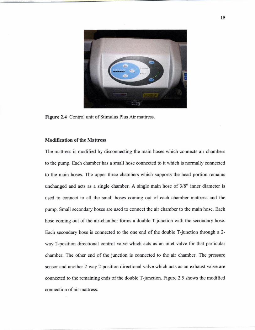
Figure 2.4 Control unit of Stimulus Plus Air mattress.
Modification of the Mattress
The mattress is modified by disconnecting the main hoses which connects air chambers
to the pump. Each chamber has a small hose connected to it which is normally connected
to the main hoses. The upper three chambers which supports the head portion remains
unchanged and acts as a single chamber. A single main hose of 3/8" inner diameter is
used to connect to all the small hoses coming out of each chamber mattress and the
pump. Small secondary hoses are used to connect the air chamber to the main hose. Each
hose coming out of the air-chamber forms a double T -junction with the secondary hose.
Each secondary hose is connected to the one end of the double T-junction through a 2-
way 2-position directional control valve which acts as an inlet valve for that particular
chamber. The other end of the junction is connected to the air chamber. The pressure
sensor and another 2-way 2-position directional valve which acts as an exhaust valve are
connected to the remaining ends of the double T -junction. Figure 2.5 shows the modified
connection of air mattress.
16
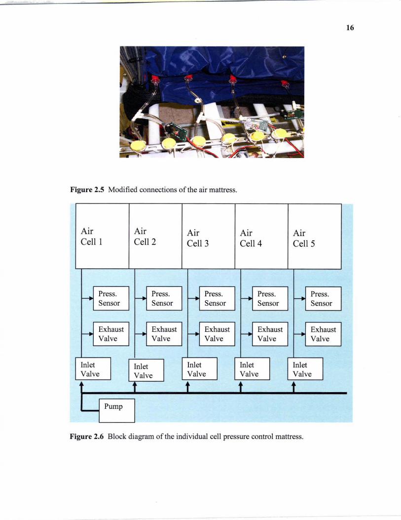
Figure 2.5 Modified connections of the air mattress.
Air Air Air Air Air Cell 1 Cell 2 Cell 3 Cell 4 CellS
- Press. - Press. - Press. f--+ Press. r--. Press. Sensor Sensor Sensor Sensor Sensor
- Exhaust - Exhaust - Exhaust - Exhaust f--+ Exhaust
Valve Valve Valve Valve Valve
Inlet Inlet Inlet Inlet Inlet Valve Valve Valve Valve Valve
t t t t Pump
Figure 2.6 Block diagram of the individual cell pressure control mattress.
17
Figure 2.6 shows the block diagram of the modified connection of the individual
cell pressure control mattress. It shows the manner in which valves, pressure sensors and
the pump is connected to the mattress. There are 32 normally closed directional valves
connected to the mattress for inflating and deflating the air chambers. One safety valve is
also provided which acts as a main exhaust valve. It is also a normally closed 2-way
directional control valve and it only opens when all other valves are closed. This provides
a way for the pressure to be release out of the system when the system is stable at a
particular setting.
2.2 Control Valves
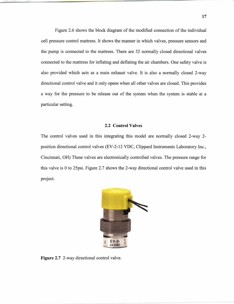
The control valves used in this integrating this model are normally closed 2-way 2-
position directional control valves (EV-2-l2 VDC, Clippard Instruments Laboratory Inc. ,
Cincinnati , OH) These valves are electronically controlled valves. The pressure range for
this valve is 0 to 2Spsi. Figure 2.7 shows the 2-way directional control valve used in this
project.
Figure 2.7 2-way directional control valve.

18
These valves are used to allow the air into the mattress and let the air out of the
mattress. Two control valves are connected to each chamber, one acting as inlet valve and
other acting as exhaust valve. The inlet valve is connected between the pump and the air
chamber. The exhaust valve is connected to the air chamber and it release air to the
atmosphere. Hence, control valves play a major role in inflation and deflation of the air
mattress.
2.3 Pressure Sensor
A pressure sensor (MPX5100AP, Motorola, Phoenix, AZ) was used to measure the air
pressure inside the air mattress. It is an integrated silicon pressure sensor. The MPX5100
series piezoresistive transducer is a monolithic silicon pressure sensor designed for a
wide range of applications using analog to digital converter (A/D) inputs [12]. In
resistive sensors, pressure changes the resistance by mechanically deforming the sensor,
enabling the resistors in a bridge circuit, for example, to detect pressure as a proportional
differential voltage across the bridge [12]. The schematic diagram is shown in the Figure
2.8.
Figure 2.8 Fully Integrated Pressure Sensor Schematic [12]
19
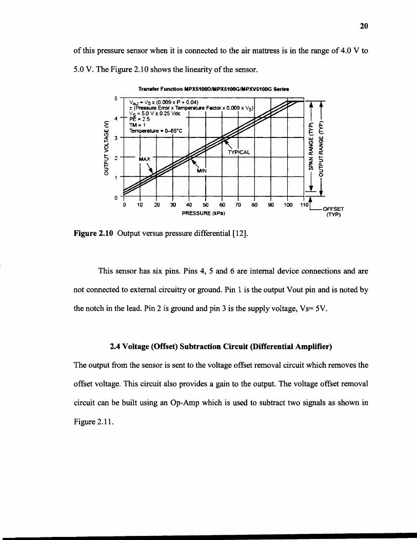
This sensor provides accurate, high level analog output signal that is proportional
to the applied pressure. It gives 2.5% maximum error over 0° to 85°C [12]. The operating
characteristics of this sensor are supply voltage Vs=5.0Vdc, temperature Ta=25°C. It
measures absolute pressure and its pressure range is 15 to 115 kPa (2.18 to 16.68psi) and
its output range is 0.2 to 4.7V.
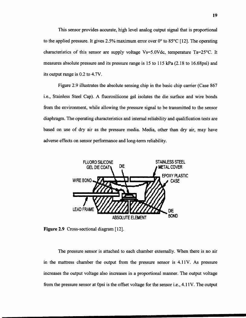
Figure 2.9 illustrates the absolute sensing chip in the basic chip carrier (Case 867
i.e., Stainless Steel Cap). A fluorosilicone gel isolates the die surface and wire bonds
from the environment, while allowing the pressure signal to be transmitted to the sensor
diaphragm. The operating characteristics and internal reliability and qualification tests are
based on use of dry air as the pressure media. Media, other than dry air, may have
adverse effects on sensor performance and long-term reliability.
Figure 2.9 Cross-sectional diagram [12].
The pressure sensor is attached to each chamber externally. When there is no air
in the mattress chamber the output from the pressure sensor is 4.11V. As pressure
increases the output voltage also increases in a proportional manner. The output voltage
from the pressure sensor at Opsi is the offset voltage for the sensor i.e., 4.11V. The output
20
of this pressure sensor when it is connected to the air mattress is in the range of 4.0 V to
5.0 V. The Figure 2.10 shows the linearity of the sensor.
Figure 2.10 Output versus pressure differential [12].
This sensor has six pins. Pins 4, 5 and 6 are internal device connections and are
not connected to external circuitry or ground. Pin 1 is the output Vout pin and is noted by
the notch in the lead. Pin 2 is ground and pin 3 is the supply voltage, Vs= 5V.
2.4 Voltage (Offset) Subtraction Circuit (Differential Amplifier)
The output from the sensor is sent to the voltage offset removal circuit which removes the
offset voltage. This circuit also provides a gain to the output. The voltage offset removal
circuit can be built using an Op-Amp which is used to subtract two signals as shown in
Figure 2.11.
21
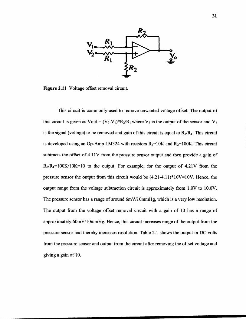
Figure 2.11 Voltage offset removal circuit.
This circuit is commonly used to remove unwanted voltage offset. The output of
this circuit is given as Vout = (V2-V1)*R2 /R1 where V2 is the output of the sensor and V 1
is the signal (voltage) to be removed and gain of this circuit is equal to R
2
/R1 . This circuit
is developed using an Op-Amp LM324 with resistors R 1=10K and R
2
=100K. This circuit
subtracts the offset of 4.11V from the pressure sensor output and then provide a gain of
R
2
/R1=100K/10K=10 to the output. For example, for the output of 4.21V from the
pressure sensor the output from this circuit would be (4.21-4.11)*10V=10V. Hence, the
output range from the voltage subtraction circuit is approximately from 1.0V to 10.0V.
The pressure sensor has a range of around 6mV/10minHg, which is a very low resolution.
The output from the voltage offset removal circuit with a gain of 10 has a range of
approximately 60mV/10mmHg. Hence, this circuit increases range of the output from the
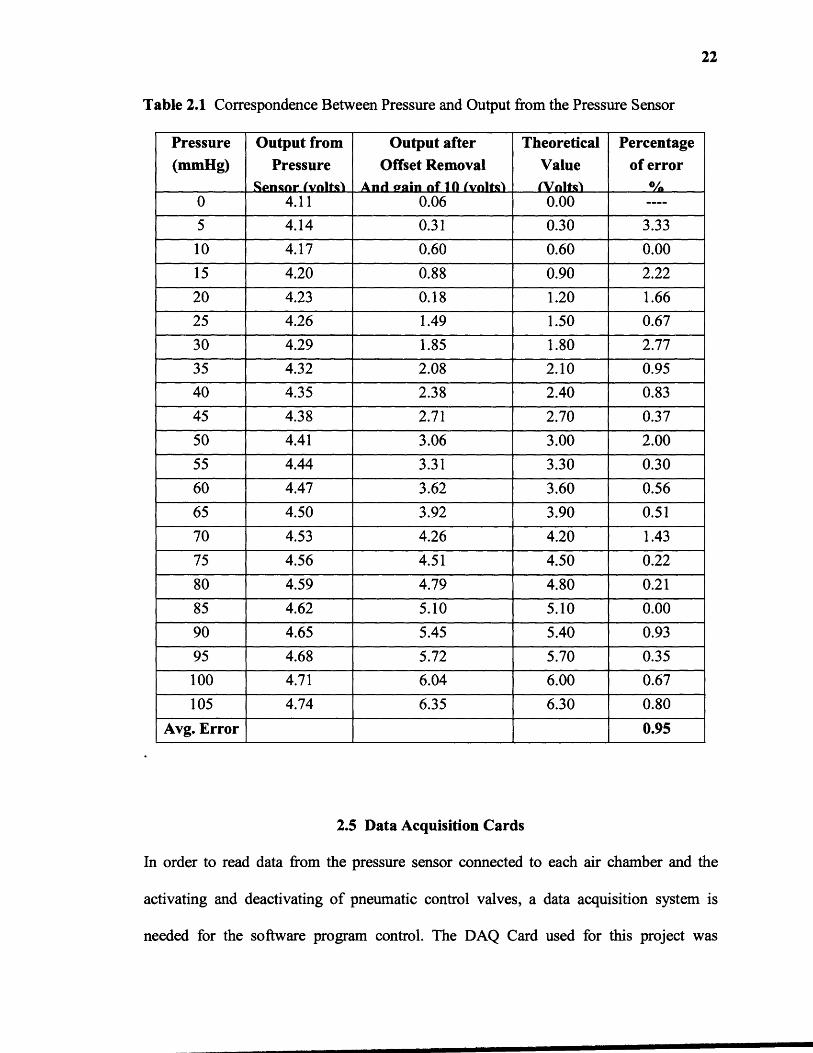
pressure sensor and thereby increases resolution. Table 2.1 shows the output in DC volts
from the pressure sensor and output from the circuit after removing the offset voltage and
giving a gain of 10.
22
Table 2.1 Correspondence Between Pressure and Output from the Pressure Sensor
Pressure(mmHg)
Output fromPressure
Sensor (volts)
Output afterOffset Removal
And (rain of 10 (volts)
TheoreticalValue(Volts)
Percentageof error
%0 4.11 0.06 0.00 ----
5 4.14 0.31 0.30 3.33
10 4.17 0.60 0.60 0.00
15 4.20 0.88 0.90 2.22
20 4.23 0.18 1.20 1.66
25 4.26 1.49 1.50 0.67
30 4.29 1.85 1.80 2.77
35 4.32 2.08 2.10 0.95
40 4.35 2.38 2.40 0.83
45 4.38 2.71 2.70 0.37
50 4.41 3.06 3.00 2.00
55 4.44 3.31 3.30 0.30
60 4.47 3.62 3.60 0.56
65 4.50 3.92 3.90 0.51
70 4.53 4.26 4.20 1.43
75 4.56 4.51 4.50 0.22
80 4.59 4.79 4.80 0.21
85 4.62 5.10 5.10 0.00
90 4.65 5.45 5.40 0.93
95 4.68 5.72 5.70 0.35
100 4.71 6.04 6.00 0.67
105 4.74 6.35 6.30 0.80
Avg. Error 0.95
2.5 Data Acquisition Cards
In order to read data from the pressure sensor connected to each air chamber and the
activating and deactivating of pneumatic control valves, a data acquisition system is
needed for the software program control. The DAQ Card used for this project was

23
National Instruments PCI-6024E which is a low cost data acquisition card which uses E
series technology to deliver high performance, reliable data acquisition capabilities in a
wide range of applications The DAQ Card E series are multifunction analog, digital and
timing [/0 cards for computer equipped with PCI slots [13]. Sampling rate up to 200 kS/s
and 12-bit resolution on 16 single-ended analog inputs can be received [13] . It has two
12-bit analog outputs, 8 lines of TTL-compatible digital [/0 and two 24-bit
counter/timers for timing [/0 [13]. The resolution of the AID converter is the number of
steps in which the input range is divided. The resolution is usually expressed as bits (n)
and the number of steps is 2 to the power n. A converter with 12-bit resolution, for
instance, divides the range into 2 " , or 4096, steps. For example, 0-10 V range will be
resolved to 0.25 mY. The PCI-6024E multifunction data acquisition card is shown in the
Figure 2.12.
Figure 2.12 NI PCI-6024E [20].

24
The software used to control the air mattress pressure was written in National
Instruments (NI) LabVIEW v.8i. The other device used for data acquisition is NI OAQ
PCI DIO 96 card. The PCI 010-96 is a 96-bit parallel digital I/O board for computers
with PCI. This board uses four 24-bit programmable peripheral interfaces (PPls). Each
PPI can be divided into three 8-bit ports. The PCI DIO 96 is flexible for interfacing to
peripherals or other computers. The board can operate in either a unidirectional or
bidirectional mode or handshake with peripheral equipment [14]. Figure 2. I 3 shows NI
OAQ PCI DIO 96 card.
PAOe~!!:..#g2
t -!'~ , - ~ r ;,If ,
Figure 2.13 NI OAQ PCI DIO 96 card [13].
The PCI DIO 96 card is connected to the CB-50LB connector block using a
ribbon cable. The CB-50LB is a termination board with 50 screw terminals for easy
connection of field I/O signals to NI OAQ devices. It also includes one 50-pin header for
direct connection to 50-pin cables. Figure 2.14 shows the CB50-LB connector block and
the ribbon cable.

25
~I
Figure 2.14 CB-50LB connector block and ribbon cable.
The analog output from the pressure sensor circuit is sent to the PCI 6024E card
through the BNC 2090 block. The PCI 6024E card send this data to the software
program. The output from the software program as a triggering signal to the control
valves is provided by the PCI DIO 96 card. The BNC 2090 connector block has 16 110
lines and the PCI DIO 96 card has 96 digital 110 lines. As this project requires 32 digital
outputs, the BNC 2090 connector block which has just 16 output lines, is not enough and
hence, there is need to use the PCI DIO 96 card having 96 digital 110 lines. So the PCI
6024E card acts as an input card and the PCI DIO 96 card acts as an output card. The
reason to use both of these cards is, as the PCI DIO 96 card cannot read analog values
from the pressure sensor but the PCI 6024E card can read it through the BNC 2090
connector block. And as the BNC 2090 card has only 16 digital 110 lines which are not
enough for the project, the PCI DIO 96 card is also used.
The development software used for data acquisition and control applications is
LabVIEW. It has extensive libraries for data acquisition, instrument control, data
analysis, and graphical data presentation. LabVIEW is a powerful graphical programming

26
language having interactive graphics, better user interface. The LabVIEW Data
Acquisition VI Library, a series of VIs for using LabVIEW with National Instruments
DAQ hardware, is included with LabVIEW. The LabVIEW Data Acquisition VI Library
is functionally equivalent to the NI-DAQ software. NI-DAQ has both high-level DAQ
I/O functions for maximum ease of use and low-level DAQ I/O functions for maximum
flexibility and performance. NI-DAQ does not sacrifice the performance of National
Instruments DAQ devices because it lets multiple devices operate at their peak
performance. NI-DAQ also internally addresses many of the complex issues between the
computer and the DAQ hardware such as programming interrupts and DMA controllers.
CHAPTER 3
CONTROL LOGIC
The individual air cell pressure control system is controlled by LabVIEW® 8.0 software.
The LabVIEW programs are called Virtual Instruments (VI's) because they imitate the
actual instrumentation of electronic instruments. LabVIEW has two basic components,
front panel and block diagram. The front panel is similar to any graphical user interface
of any language program. It consists of the indicators, controls, led display, knobs etc.
The displays can be user controlled or may be already a constant value, depending on the
need of the system. The block diagram appears as a circuit diagram of the instrument. It
consists of several blocks and sub VIs needed for the software to work as per the system
needs. The flow of the data in the block diagram is from the left to right. It includes the
data acquisition blocks for reading the data from the device attached to it. The function
palette consists of all the functions used to program the VI's. It is widely used as it is user
friendly and has good data acquisition ability.
3.1 Software Logic
The front panel in this project is divided into two parts, one part for the programmer and
other part for the end user. The programmer part contains controls for the pressure range,
indicators for the pressure in each air chamber, indicators for the activation or
deactivation status of the control valves, selection of the firmness, start and stop buttons.
The end user part contains start and stop activation buttons, selection of the mode of
operation of the air mattress i.e., standard air pressure mattress, alternating pressure
27
28
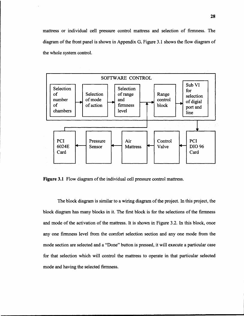
mattress or individual cell pressure control mattress and selection of firmness. The
diagram of the front panel is shown in Appendix G. Figure 3.1 shows the flow diagram of
the whole system control.
Figure 3.1 Flow diagram of the individual cell pressure control mattress.
The block diagram is similar to a wiring diagram of the project. In this project, the
block diagram has many blocks in it. The first block is for the selections of the firmness
and mode of the activation of the mattress. It is shown in Figure 3.2. In this block, once
any one firmness level from the comfort selection section and any one mode from the
mode section are selected and a "Done" button is pressed, it will execute a particular case
for that selection which will control the mattress to operate in that particular selected
mode and having the selected firmness.
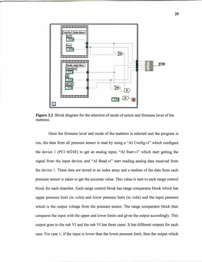
m Figure 3.2 Block diagram for the selection of mode of action and firmness level of the mattress.
29
Once the firmness level and mode of the mattress is selected and the program is
run, the data from all pressure sensor is read by using a "AI Config.vi" which configure
the device 1 (PC I 6024E) to get an analog input, "AI Start. vi" which start getting the
signal from the input device, and "AI Read.vi" start reading analog data received from
the device 1. These data are stored in an index array and a median of the data from each
pressure sensor is taken to get the accurate value. This value is sent to each range control
block for each chamber. Each range control block has range comparator block which has
upper pressure limit (in volts) and lower pressure limit (in volts) and the input pressure
which is the output voltage from the pressure sensor. The range comparator block then
compares the input with the upper and lower limits and gives the output accordingly. This
output goes to the sub VI and the sub VI has three cases. It has different outputs for each
case. For case 1, if the input is lower than the lower pressure limit, then the output which
30
controls the inlet valve is high and the one controlling the exhaust valve is low, for case
2, if the input is greater than the upper pressure limit, then the output controlling the inlet
valve is low and the output controlling the exhaust valve is high. In the last case, case 3,
when the input is within the upper and lower pressure limits, then both the outputs
controlling inlet and exhaust valve are low.
These cases are for the selection of the digital line of the digital port of the PCI
DIO 96 card to the control the inflation and deflation of the air chamber. Each digital port
has eight digital lines. For controlling the pressure in each chamber it requires two digital
lines. One is for the inlet valve and the other is for the exhaust valve. Therefore, one
digital port can control eight valves four inlet valves and four exhaust valves of four
chambers. For example, if the pressure value from the pressure sensor attached to the first
air chamber is over the upper range than it gives a low output to the digital line 0 which is
connected to the inlet valve and high output to digital line 1 which is connected to the
exhaust valve of the first chamber of the air mattress. Hence, each sub VI controls two
digital line and two valves and one chamber pressure. We have four sub VIs each for
lines 0 and 1, lines 2 and 3, lines 4 and 5, and lines 6 and 7. Hence, for controlling
pressure in all the 16 air chambers of the mattress, and 16 range control blocks each are
required and having one range control function, four sub VIs and four digital port each
controlling eight digital lines or eight control valves. The allocation of the digital port and
lines for each chamber is shown below in table 3.1.
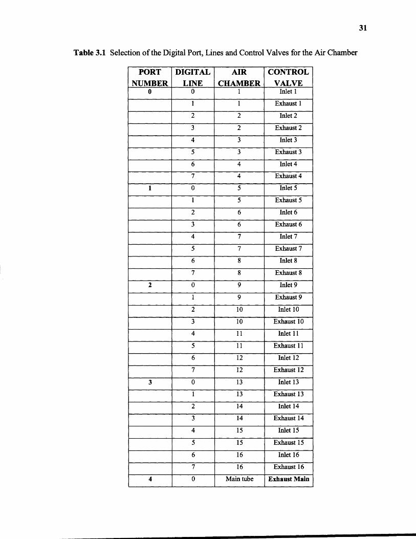
Table 3.1 Selection of the Digital Port, Lines and Control Valves for the Air Chamber
PORTNUMBER
DIGITALLINE
AIRCHAMBER
CONTROLVALVE
0 0 1 Inlet 1
1 1 Exhaust 1
2 2 Inlet 2
3 2 Exhaust 2
4 3 Inlet 3
5 3 Exhaust 3
6 4 Inlet 4
7 4 Exhaust 4
1 0 5 Inlet 5
1 5 Exhaust 5
2 6 Inlet 6
3 6 Exhaust 6
4 7 Inlet 7
5 7 Exhaust 7
6 8 Inlet 8
7 8 Exhaust 8
2 0 9 Inlet 9
1 9 Exhaust 9
2 10 Inlet 10
3 10 Exhaust 10
4 11 Inlet 11
5 11 Exhaust 11
6 12 Inlet 12
7 12 Exhaust 12
3 0 13 Inlet 13
1 13 Exhaust 13
2 14 Inlet 14
3 14 Exhaust 14
4 15 Inlet 15
5 15 Exhaust 15
6 16 Inlet 16
7 16 Exhaust 16
4 0 Main tube Exhaust Main
31
32
The last phase of the block diagram is for the control of the main exhaust valve.
When the preset pressure for each chamber is set by the programmer is reached, all inlet
and exhaust valves connected to the chambers get closed and hence, the air pressure
coming from the pump needs some way to be released out. So a main exhaust valve
which is connected to the main tube is needed to be open to release that pressure. It acts
as a safety valve.
3.2 Software Controlled Features
This system has more flexibility than compared to other air mattresses currently used for
prevention of pressure sores. It has flexibility in selecting any number of chambers to be
operated at a time, range of firmness level, firmness level, and mode of action of the
mattress. If the firmness level is selected as 1) by clicking one button named "Firm" on
the front panel, a medical staff can inflate all chambers to firm. This would assist in
helping people to get in or out of the bed and 2) by clicking "Soft" button on the front
panel, all chambers can be deflated up to soft firmness. It is also possible to use this
mattress as a standard air mattress, alternating air pressure mattress as well as few other
patterns. This mattress can be operated in different modes such as 1) AB mode
alternating pressure mattress, where A and B will be different pressure 2) ABC mode
alternating pressure mattress where A, B and C are different pressure. More modes such
as ABCD, ABCDE, etc. can be selected.
The modified mattress is a closed loop system and it can respond to the change in
pressure inside the chamber either by inflating or deflating the chamber. For example, if
an external force is applied on the mattress, then the pressure inside those chambers

33
where the external force is applied will increases. The pressure sensor connected to those
cells will sense this increase in pressure and will give an increased value of input to the
system. If the change in pressure inside the chamber is within the lower and upper limits
of pressure for that chamber, then the system will not respond and remain stable. But if
the change is pressure is not within the range, then the software will give an output to
control directional control valves to make the necessary changes.

CHAPTER 4
VERIFICATION, RELIABILITY AND SAFETY OF THE SYSTEM
4.1 Verification of the System
Verification of the system is required in any project before implementing it. To verify the
system it is compared with some medium or its performance it evaluated. The system
should be accurate and reliable enough to fulfill the purpose for which it is developed. To
validate the individual cell pressure control mattress, the accuracy, the repeatability and
the feedback validation tests are conducted and the percentage of error is calculated.
4.1.1 Accuracy Test
For the accuracy test, the system is operated in 1) ABCDE mode and Soft firmness level
and in 2) ABCDE mode and Firm firmness level. For this, five chambers are selected
other than the chambers supporting head. At each five chambers a sphygmomanometer is
connected to check that when the system is operated, the pressure hold by each chamber
match the pressure shown by the respective sphygmomanometer connected to that
particular chamber. For the ABCDE mode of operation and the Soft firmness level, each
of the five cells has a different pressure ranges between 20mmHg to 50mmHg, and for
the ABCDE mode of operation and Firm firmness level, each of the five cells has a
different pressure range between 50mmHg to 75mmHg. The output of each pressure
sensor is noted which is in volts. The mean value of the readings is calculated and
compared with the sphygmomanometer reading. Percentage of error is calculated for each
of the five chambers to check the accuracy of the system. The following table shows the
details of the accuracy check of the system.
34
34
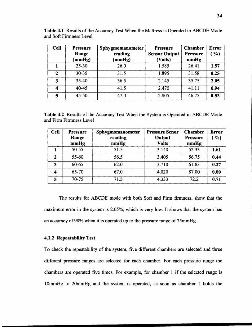
Table 4.1 Results of the Accuracy Test When the Mattress is Operated in ABCDE Modeand Soft Firmness Level
Cell PressureRange
(mmHg)
Sphygmomanometerreading(mmHg)
PressureSensor Output
(Volts)
ChamberPressuremmHg
Error( %)
1 25-30 26.0 1.585 26.41 1.57
2 30-35 31.5 1.895 31.58 0.25
3 35-40 36.5 2.145 35.75 2.05
4 40-45 41.5 2.470 41.11 0.94
5 45-50 47.0 2.805 46.75 0.53
Table 4.2 Results of the Accuracy Test When the System is Operated in ABCDE Modeand Firm Firmness Level
Cell PressureRangemmHg
SphygmomanometerreadingmmHg
Pressure SenorOutputVolts
ChamberPressuremmHg
Error( %)
1 50-55 51.5 3.140 52.33 1.61
2 55-60 56.5 3.405 56.75 0.44
3 60-65 62.0 3.710 61.83 0.27
4 65-70 67.0 4.020 87.00 0.00
5 70-75 71.5 4.333 72.2 0.71
The results for ABCDE mode with both Soft and Firm firmness, show that the
maximum error in the system is 2.05%, which is very low. It shows that the system has
an accuracy of 98% when it is operated up to the pressure range of 75mmHg.
4.1.2 Repeatability Test
To check the repeatability of the system, five different chambers are selected and three
different pressure ranges are selected for each chamber. For each pressure range the
chambers are operated five times. For example, for chamber 1 if the selected range is
10mmHg to 20mmHg and the system is operated, as soon as chamber 1 holds the

35
pressure within 10mmHg to 20mmHg pressure range, the first reading from the pressure
sensor is noted. For the second reading, chamber 1 is deflated totally and it is operated
again for the same pressure range. When it holds the pressure within that pressure limits,
the second reading of the pressure sensor output is noted. This is repeated five times for
each five chamber. Different ranges are selected to check the repeatability of the system
at various pressures. Table 4.3 shows the readings obtained and the calculated mean,
variance and standard deviation for these readings to verify the system.
Table 4.3 Results of the Repeatability Test of the System
Cell PressureRangemmHg
Readings (Volts)Variance S.D
Error%1 2 3 4 5 Mean
1
30-35 1.96 2.02 2.01 1.95 1.98 1.99 0.00078 0.029 1.45
50-55 3.07 3.08 3.11 3.10 3.07 3.09 0.00028 0.017 0.55
70-75 4.28 4.32 4.27 4.33 4.39 4.32 0.00182 0.043 0.99
2
40-45 2.47 2.41 2.47 2.51 2.53 2.48 0.00170 0.041 1.65
60-65 3.69 3.65 3.77 3.75 3.69 3.71 0.00192 0.044 1.19
80-85 4.82 4.83 4.81 4.94 4.88 4.86 0.00212 0.046 0.94
3
50-55 3.12 3.24 3.18 3.12 3.16 3.17 0.00202 0.045 1.42
70-75 4.36 4.31 4.29 4.34 4.30 4.32 0.00068 0.026 0.60
85-90 5.24 5.14 5.13 5.25 5.23 5.20 0.00270 0.051 0.98
4
60-65 3.74 3.71 3.74 3.80 3.79 3.75 0.00118 0.034 0.91
40-45 2.45 2.50 2.60 2.43 2.54 2.50 0.00380 0.062 2.48
20-25 1.36 1.30 1.23 1.33 1.34 1.31 0.00176 0.042 3.21
5
70-75 4.33 4.30 4.26 4.36 4.29 4.31 0.00118 0.034 0.79
30-35 1.87 1.88 1.90 1.96 1.94 1.91 0.00134 0.037 1.93
50-55 3.16 3.23 3.14 3.26 3.19 3.19 0.00198 0.044 1.37

36
Table 4.3 shows that for each chamber and for each range the readings are not
spread more away from the mean. Even the system has maximum of 3.21% of error when
the system is operated number of times. This error is very low and the results show that
the system is reliable.
4.1.3 Validation of the System Feedback
The individual cell pressure control mattress is a closed loop system and it can give
feedback to the system. To check the feedback of the system, a small pilot study is shown
in this section. In this test, when there is a subject on the mattress, two consecutive cells
supporting the buttocks region of the patient are selected. The pressure range selected for
cell 1 is 60-70mmHg and for cell 2 is 50-60mmHg. The cell 1 supports the high pressure
region of the buttocks and cell 2 supports the low pressure region of the buttocks. The
system is operated by selecting a delay of 6 seconds for the feedback loop. The system
has the ability to read the pressure sensor output every second. For this test, the pressure
sensor output is displayed every 2 seconds. When the system reach a stable state i.e.,
when each cells holds the preset pressure and all the inlet and exhaust valves connected
to each cell are closed, the subject is told to move his high pressure region of buttocks
from cell 1 to cell 2. This causes change in pressures in both the cells. When the subject
will move high pressure region of his buttocks on cell 2, the pressure in cell 1 will
decrease and the pressure in cell 2 will increase. And the system becomes unstable at that
time. The output from the pressure sensors connected to cell 1 and cell 2 are noted every
2 seconds. As the system has a delay of 6 seconds, the control valves will get a feedback
every 6 seconds. The feedbacks for control valves connected to cell 1 and cell 2 are
noted. These feedbacks, at every 6 seconds, compares the new recorded pressure sensor

37
output with the upper and lower limits for that particular cell and accordingly either
inflate or deflate the mattress. When the pressures inside cell 1 and cell 2 returns back to
the preset range, the output of the pressure sensor is noted. The pressure sensor output at
the start and at the end of the test is compared to check the system ability to recover the
change is pressure. This test is performed to check the working of the feedback loop. The
expected results for this test are when the subject moves from position 1 to position 2 and
if that position is maintained for longer than 6 seconds, the inlet valve for the cell 1
should open to raise the pressure back to specified levels, and the exhaust valve for cell 2
should open to release air and lower the pressure in cell2 to the specified levels. Table 4.4
shows the output of the pressure sensor connected to cell 1 and cell 2 when a patient
moves his body from one position to another.
38
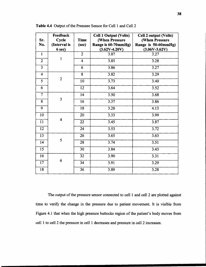
Table 4.4 Output of the Pressure Sensor for Cell 1 and Cell 2
Sr.No.
FeedbackCycle
(Interval is6 sec)
Time(sec)
Cell 1 Output (Volts)(When Pressure
Range is 60-70mmHg)(3.62V-4.20V)
Cell 2 output (Volts)(When Pressure
Range is 50-60mmHg)(3.06V-3.62V)
11
2 3.87 3.27
2 4 3.85 3.28
3 6 3.86 3.27
42
8 3.82 3.29
5 10 3.73 3.40
6 12 3.64 3.52
73
14 3.50 3.68
8 16 3.37 3.86
9 18 3.28 4.13
104
20 3.33 3.99
11 22 3.45 3.87
12 24 3.53 3.72
135
26 3.65 3.63
14 28 3.74 3.51
15 30 3.84 3.43
166
32 3.90 3.31
17 34 3.91 3.29
18 36 3.89 3.28
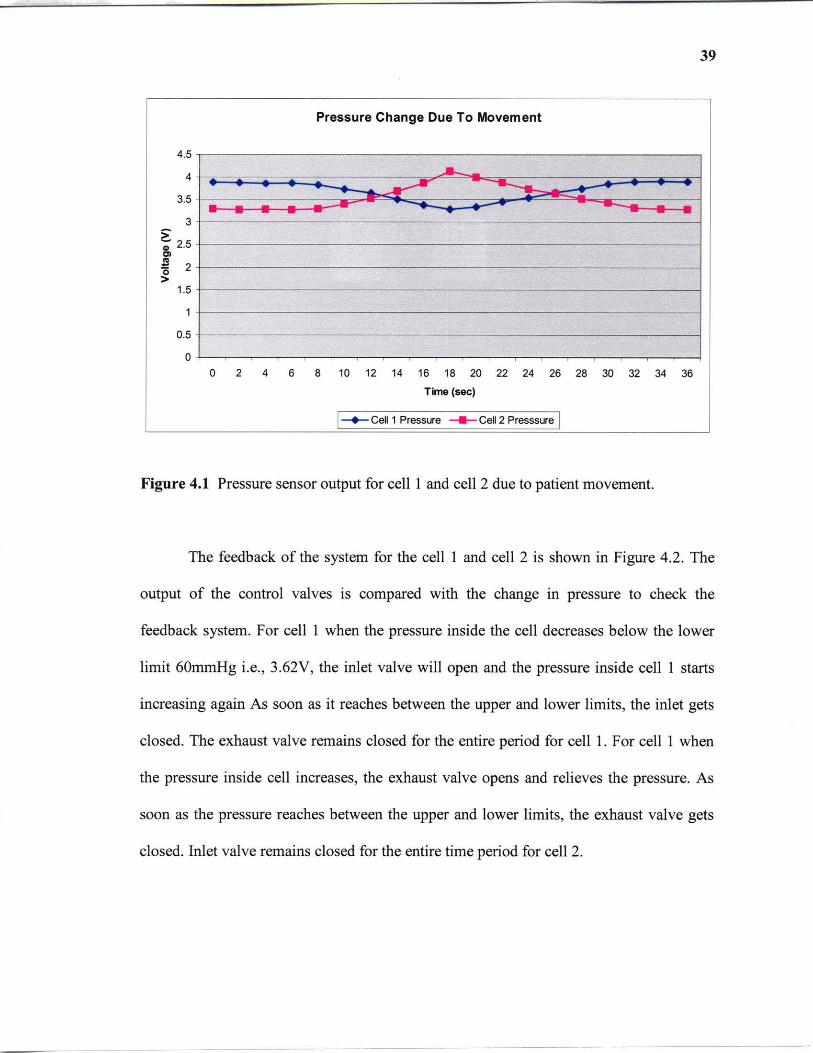
The output of the pressure sensor connected to cell 1 and cell 2 are plotted against
time to verify the change in the pressure due to patient movement. It is visible from
Figure 4.1 that when the high pressure buttocks region of the patient's body moves from
cell 1 to cell 2 the pressure in cell 1 decreases and pressure in cell 2 increases.
39
Pressure Change Due To Movement
4.5
4 ~ ...---- ----3.5 ~
3 > -; 2.5
'" ~ 2 >
1.5
1
0.5
0 0 2 4 6 8 10 12 14 16 18 20 22 24 26 28 30 32 34 36
Time (sec)
I-+-Cell 1 Pressure ~ Cell 2 Presssure I
Figure 4.1 Pressure sensor output for cell I and cell 2 due to patient movement.
The feedback of the system for the cell I and cell 2 is shown in Figure 4.2. The
output of the control valves is compared with the change in pressure to check the
feedback system. For cell I when the pressure inside the cell decreases below the lower
limit 60mmHg i.e. , 3.62V, the inlet valve will open and the pressure inside cell I starts
increasing again As soon as it reaches between the upper and lower limits, the inlet gets
closed. The exhaust valve remains closed for the entire period for cell 1. For cell I when
the pressure inside cell increases, the exhaust valve opens and relieves the pressure. As
soon as the pressure reaches between the upper and lower limits, the exhaust valve gets
closed. Inlet valve remains closed for the entire time period for cell 2.
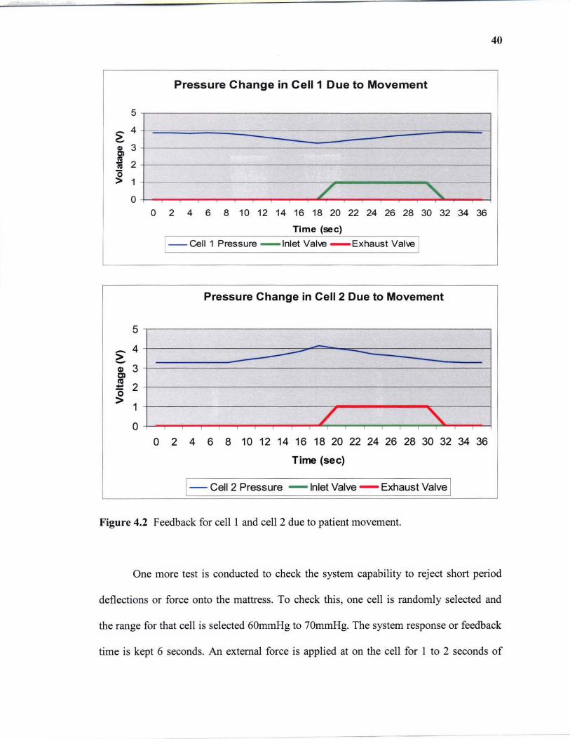
40
Pressure Change in Cell 1 Due to Movement
5
~ 4
8, 3
~ 2
~ 1
0 / "'\.. 0 2 4 6 8 10 12 14 16 18 20 22 24 26 28 30 32 34 36
Time (sec)
1--CeIl1 Pressure - Inlet Valve - Exhaust Valve I
Pressure Change in Cell 2 Due to Movement
5
~ 4 -> -G> 3 Cl al
2 -'0 > 1
/ " 0
0 2 4 6 8 10 12 14 16 18 20 22 24 26 28 30 32 34 36
Time (sec)
1- Cell 2 Pressure - Inlet Valve - Exhaust Valve 1 Figure 4.2 Feedback for cell I and cell 2 due to patient movement.
One more test is conducted to check the system capability to reject short period
deflections or force onto the mattress. To check this, one cell is randomly selected and
the range for that cell is selected 60mmHg to 70mmHg. The system response or feedback
time is kept 6 seconds. An external force is applied at on the cell for I to 2 seconds of

41
time period. The output of the pressure sensor is measured at every second. The expected
result for this test is if an external force is applied on the cell between the time intervals
of 6 seconds, which is the system response time, the system should not respond to the
applied external force and none of the valves should open. Table 4.5 shows the results of
the test.
Table 4.5 Pressure Sensor Output for Short Period Impulse Force
Sr.No
FeedbackCycle
(Intervalis 6 sec)
Time(sec)
PressureSensorOutput(Volts)
1 1 3.87
2 2 3.89
3 3 4.60
4 1 4 4.21
5 5 3.90
6 6 3.87
7 7 3.85
8 8 3.86
9 9 3.89
10 2 10 3.88
11 11 3.87 --
12 12 3.86
The output of the pressure sensor increases when an external force is applied on
the cell. It is clear from the results that when the force was applied at the third second.
This increases the output of the pressure sensor. As the feedback has a delay of 6
seconds, the system would compare the output of the pressure sensor with the upper and
lower limits of pressure at the every sixth second and respond accordingly. As the system

42
recovers the original pressure before the sixth second, it will not respond to that change.
And the output of the inlet and exhaust valves connected to that cell is also low as they do
not receive any feedback and remain closed. The output from the pressure sensor is
compared with the output of the inlet and exhaust control valves connected to that
chamber. The following figure shows that. Figure 4.3 shows the pressure change and
feedback of the system when a short period impulse force in applied on a cell.
Pressure change in cell
5
4 ,.... -~
i' 3
~ 2
1
0
1 2 3 4 5 6 7 8 9 10 11 12
Time (sec)
1-- Cell Pressure -- Inlet Valve - Exhaust Valve 1
Figure 4.3 Pressure change and system feedback for a short period impulse force.
4.2 Reliability and Safety ofthe System
The reliability and safety check of the any system is also necessary before implementing
it. The data received from the pressure sensor during system check matches with the
theoretical values with an average error of 0.95%. The output from the pressure sensor is
linear with respect to the air pressure inside the mattress. The system is a closed looped
system which responds well.

43
To check the reliability and safety of the system, some of the situations are taken
into consideration. For example, if the main analog power (120V) turns off. As this
system controls the air pressure using electronically control normally closed 2-way
directional control valves, as soon as the power turns off both the inlet and exhaust
control valves get closed and also the pump shuts down. So the air pressure inside the
mattress at that particular time would remain in the mattress i.e., no inflation or deflation
can occur.
In another situation, when the software logic has a problem such as either in
comparing the chamber pressure with the preset range of the pressure, or in selection of
proper digital port or digital line for providing a triggering signal to the control valves,
the software is developed in such a way that it has the ability to detect a problem in the
system and even it can show in which part the of the system the problem exists. An LED
corresponding to that particular chamber will flash showing the fault in that portion of the
system. Thus, instead of checking the whole system only a small part of the system may
require service or replacement which would make the operator's work easier.
In a situation, when there is a crack in a mattress or in tubes, due to leakage of air
in the system, the preset pressure inside the chambers would not be reached. But as in this
system, the pump is controlled by the software, it will detect if the pump remains ON for
more than 5 minutes continuously, the software will then turn it OFF and a LED will
blink indicating the problem. Hence, it will make the system safer.
The system uses upper and lower range of pressure for each chamber as a
reference for comparing the input pressure instead of just one reference. This will make
the system more stable by avoiding small distortion in the pressure inside the chamber.

44
For example, if the patient movers or roll over a little, there will be a little change in
pressure inside the chambers. But as there is a upper and lower limits of pressure for each
chamber, if this small change in pressure inside the chamber is within that limits than the
system will not respond and remain stable. This will make the system more reliable
against unwanted disturbance.
Some of the limitations of the individual cell pressure control air mattress are as it
uses an external pump which makes noise which might cause irritation to the patients. As
the system has mechanical components, maintenance and servicing would be a problem.
It requires a computer and a lot of hardware to operate and hence, it requires more care
and space.

CHAPTER 5
EXPERIMENTATION
The duration of the human interface experiment for this type of research is very long,
often in years. It is also hard to get patients for this type of research. Therefore, due to the
time limitation a human interface experiment is out of the scope of master's thesis. Thus,
a research plan of experiment is proposed. Healthcare professionals attempt to reduce the
incidence of severe pressure sores by the identification of people at high risk and the use
of prevention strategies such as pressure-relieving equipment. Many studies have been
conducted for evaluation of methods used for prevention and treatment of pressure sores
[15]. Prevention studies also conducted to evaluate the prevalence and incidence of
pressure ulcers and their relationship with different mattresses [16]. In treatment studies,
pressure relieving interventions are evaluated for the healing of pressure sores. The
objectives of these studies are to compare different pressure relieving cushions, beds,
mattress overlays and mattresses and to find out which one reduce the incidence of
pressure sores compared to others, to find out which support surfaces increase the healing
rate of pressure sores compared to other support surfaces. Each of these studies requires
data sources, type of trials, pressure relieving interventions and results.
5.1 Identifying Population for Application of Methods
To implement any method the first step is to identify people at risk. As interventions to
prevent pressure sores can be very expensive, the resources should be targeted at patients
who are at high risk of developing sores. These high risk patients are identified using
45
46
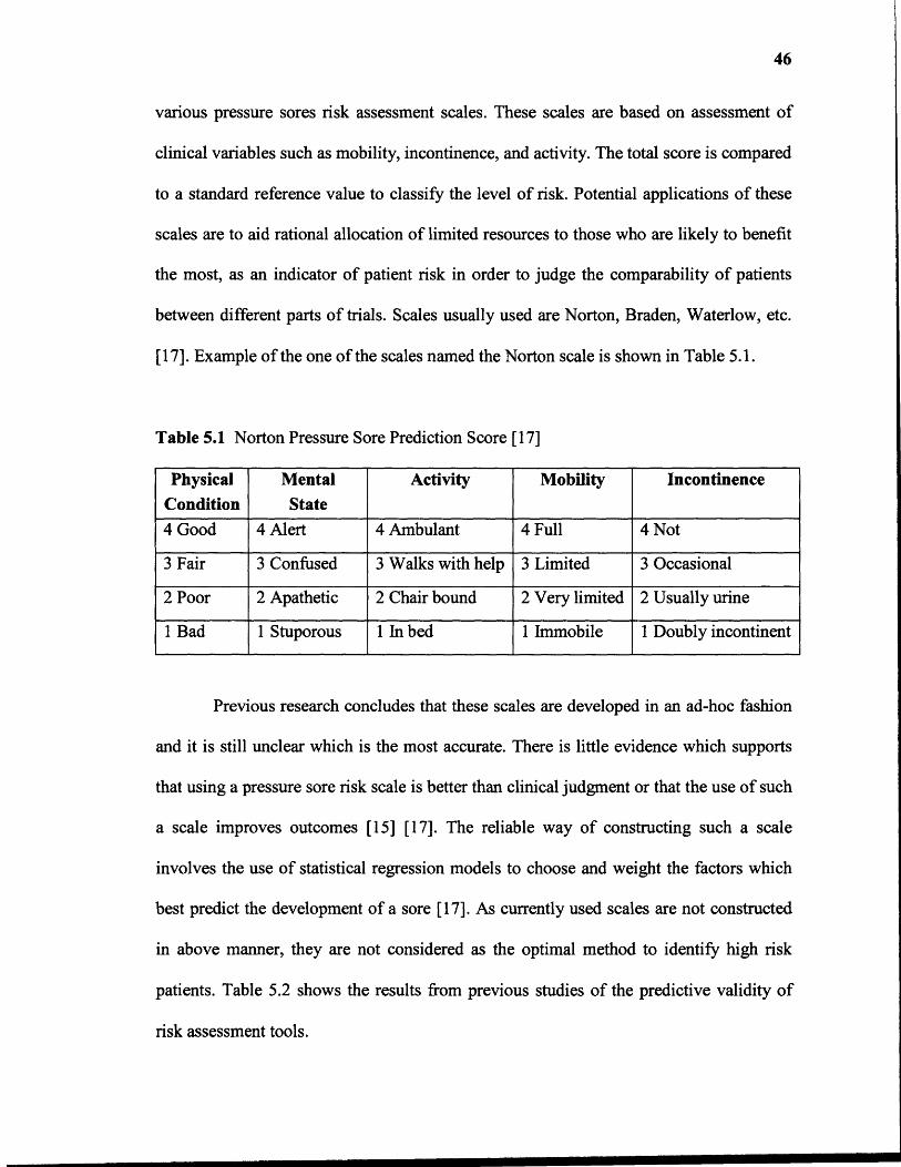
various pressure sores risk assessment scales. These scales are based on assessment of
clinical variables such as mobility, incontinence, and activity. The total score is compared
to a standard reference value to classify the level of risk. Potential applications of these
scales are to aid rational allocation of limited resources to those who are likely to benefit
the most, as an indicator of patient risk in order to judge the comparability of patients
between different parts of trials. Scales usually used are Norton, Braden, Waterlow, etc.
[17]. Example of the one of the scales named the Norton scale is shown in Table 5.1.
Table 5.1 Norton Pressure Sore Prediction Score [17]
PhysicalCondition
MentalState
Activity Mobility Incontinence
4 Good 4 Alert 4 Ambulant 4 Full 4 Not
3 Fair 3 Confused 3 Walks with help 3 Limited 3 Occasional
2 Poor 2 Apathetic 2 Chair bound 2 Very limited 2 Usually urine
1 Bad 1 Stuporous 1 In bed 1 Immobile 1 Doubly incontinent
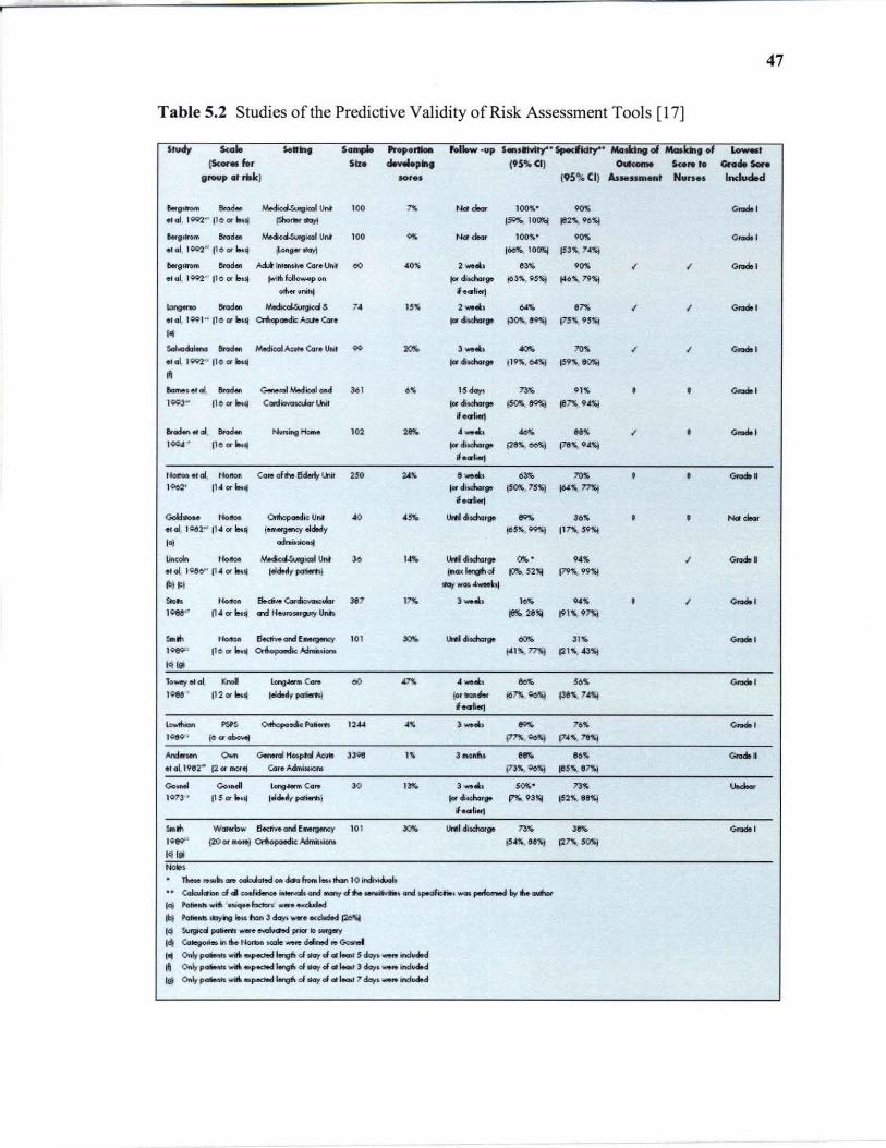
Previous research concludes that these scales are developed in an ad-hoc fashion
and it is still unclear which is the most accurate. There is little evidence which supports
that using a pressure sore risk scale is better than clinical judgment or that the use of such
a scale improves outcomes [15] [17]. The reliable way of constructing such a scale
involves the use of statistical regression models to choose and weight the factors which
best predict the development of a sore [17]. As currently used scales are not constructed
in above manner, they are not considered as the optimal method to identify high risk
patients. Table 5.2 shows the results from previous studies of the predictive validity of
risk assessment tools.
47
Table 5.2 Studies of the Predictive Validity of Risk Assessment Tools [17)
'hNy 5<.10 ...... ....... ..... - hliow ·up .... ......,. .............. Mo ....... _ ..... f '-00, (Scor .. for .ID """',., 195%(11 -.. ....... _ .......
group lit rtH:J Mr •• 195\1. CII At ..... _t N.n •• Included
........ ""'. MediuU.urgiCICIl Un~ ' 00 '" Nd , ... lOOll'.· .... Goado , .. 01, 1QQ2" 1I0 01' bUI ~"''''' 15Q!IE,. IOC5j flI2""96~
~81"'" ... d. .Y.odi(~icaIU"t to. '" Nd,'" JOO!\· . .,. 0 ..... ' .,al. 10C>2" 11 0 or"lj ~9"tI\;Jyj 160,.< IO~ jS3'-74~
&.911l'0III ""'~ AU 11IIerKi'<'O Cor. Unit 00 AO!\ 2 ...... , 83" ,.,. I I 0 ..... ' " <II, 1Q92" Iloor"'" ""iIiI~l~pon I« diKha,g. 163l1'., 05%) "'6~. 19":1
0111" uni~ I.criierj
~ ...... ""'. oY.edkol.Wrgicd .s ,. 15% , ..... .... .'" I I Goado ,
• ,aI, 1001 " 1'001' I.nl 0IbapaMi:: ~ ear • tordiKharp P'"',"'l 175!\, 95'ij ,. ............ ...... MedicalAcvNo (ar. UNI .. ""' 3 ....... ""' ""' I I Goado 1 .. ai, 1QQ2" 110 CII' "Ij Iordi~ .. 119';, OI~ 159'\. 1tOSI ~
&._~ .. aI ...... C~MedicoloM 36' ,~ 15 day. 73,. o'S • • Goadol )003" 11001' 1M" <:Gldiowdar lhit jardiKMrIJll i50!1i.,~ ..,n9A~ ,....., erocH.n« 01 ""'- ....... ..,... ,., , .. ._.&: . 00" ..,. I • Goadol 100"" • 110 or ... jarditd-.,.. {28". oo~ 118", GAS!
I.oriert UOltOu.aI, , ..... Cg,.of .... ~U1i1 25. "''' 8 ''''.1:, 63,. ""' • • Goado' ' 002' 1'·01'''''''' torditdooorp (S0!r., 75~ "'~. "'I
if •• 1ierJ
Golchlo" Norton Orlhql<*lk Uf\' .. .... lII'*Idim.gt "'" 36,. • • Nd "-etol, 1~2" 114 or i&ul t_III01lJ1OCY ekt.rly (O5". ~) 117X. 59~
I~ ocIniuiolllj
lincdn Horton Medkd.Surgicol Unt ,. , ... ~didla'. "" . 9'" I Goado • _,01..10,,1)" 114 or ~II lekieoliy pcmr.nj (00< ........ " P!'-. 52", [79~. 99~
~l ' I ~-,~'" 0- ,'-' fl.cMo c..~ ..... , .17 "" , ..... \0" .. ~ • I Goado , , .... 11 4or~" G'1d HelHOwtl'Jry link 18!' 211~ 1915 9~
,., .. ,'-' 5.ai .... and f Mf9I'I'Y 10' .,.. lIrIiIcI!tda. ""' Jl)i, "'"'" , ,- 11oorb" ~ A:IrMt.icno +415. 71'S} e215 • .&3~
I~'" lo.....y <II aI "'" lq ... C_ 00 m.
4 __ • .... ,,~
"'"'" 1 , .... 112or"" IeIdeolly pori«tt) ", ...... i6~, Qo!q Illl'. "~ '_'"-1 ....... """ OItftepaock PoHm "44 .. J_'&:. "" 76~ Goado 1 ,- , (001 olxr...! ,"". Qo~ 1745, 18%1
.......... 0.. G.nenII HoI.pial Al::11110 ,,,. I '; , ..... .... 116'; Goado. .,0\.1982· 12 01' lMtet (Q'oAdflli .. ~ 17J,., 9c~ ,115';, 11""1
Go ..... 0.." lore .... '" Co,. ,. ''''' J_'&:. ,O!<. 1JS """"" I07J ' 11501 !.ul 1.Id..y p<IIiwh.j t«ditcM,,. ~93'" 152". l1li"1 I.CO'Ii.rJ
,., .. Waterb .... 6eelive ond f .. rgen.:y '01 "'" UNIOIscMr,. 73 .. ''''' Goadol
,-' (20 Of "'ON] Cnbopctedic ..-G"vulono (545. &6"1 .'" SOlO! Ict la NoO,
n-. .. ",Its _ cabJat.d on cba ftono 1_. INn 10 itd....;cl.oh .. CoIoibCti 4 .. coJioMra ~oncl --.,. cI ............ oncI ~i:"'. _ ptdom..d bot !he 0IIIIIh:.r
'" PoM ... wiIII MiqeeJ..dcro ... _ • ....d.detl
ibJ , ..... Ml:l'jhg "U han 3 dcry. __ ..:ckded J2d.I'4
14 Su9ca poIiem .... e -'IOChd prior 1O.wg.y
1<1 Cotevo"- in" 1b'Dn .... _R d-...t .. ao.n.I I. Onlr poIiMft .... iIIrI -.p«1IId Mrv' d tfa)' cI III '-t 5 clay. _ in:W.d
~ Otdy poIiMoto ""ift .... ectood !.relit cI..., J at '-t J ~. _ indvO.d
I~ ~ pcMMl""iI/r, .... «t&d ~ cI..., J at '-t 7 cIcry,_ indvO.d
48
There is a great variation in the estimates of predictive validity both across scales
and between assessments of the same scale. As there is a large variation between the
settings and the methods, it is not possible to make better comparisons of the predictive
validity of these scales.
5.2 Types of Pressure Relieving Interventions
The aim of pressure sore prevention strategies is to reduce the magnitude and/or duration
of pressure between a patient and their support surface (the interface pressure). This may
be achieved by regular manual repositioning (e.g. 2-hourly turning), or by using pressure-
relieving support surfaces such as cushions, mattress overlays, replacement mattresses.
This project focuses on the effectiveness of risk prediction and pressure reliving
mattresses. Other aspects of pressure sore managements are not considered. Pressure
relieving mattresses are constant low pressure devices and alternating pressure devices.
Alternating pressure (AP) mattresses usually alternate inflate and deflate the air cells and
hence, generate alternating high and low pressures between the patient's body and
support surface. These mattresses reduce the duration of the applied pressure and provide
a continuous redistribution of the pressure beneath the patient. Constant low pressure
(CLP) mattresses are grouped according to foam, foam and air, foam and gel, air
fluidized. These mattresses mould around the patient body to distribute patient's weight
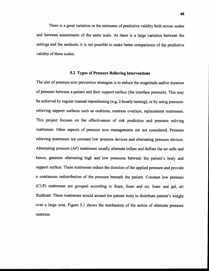
over a large area. Figure 5.1 shows the mechanism of the action of alternate pressure
mattress.

Figure 5.1 Diagram showing the mechanism of action of alternating pressure devices [ 17].
5.3 Evaluating Pressure Relieving Intervention
49
Pressure relieving interventions are evaluated for prevention or treatment of pressure
sores. Randomized controlled trials are used for evaluation because; they provide the
most reliable evidence for the efficacy of interventions. Random allocation of patients to
treatment and control groups improves the comparability of the groups and so differences
in outcomes can be more confidently attributed to a particular treatment, once random
error is excluded by significance testing [17]. Many studies have simply measured the
interface pressure between the body and the support surface. Interface pressure is an
intermediate or surrogate outcome measure which has many limitations as a proxy for
clinical outcomes [17]. The effect of the mattress for prevention of pressure sores is

50
assessed by the presence of at least one pressure ulcer of any stage and to the presence of
at least one pressure ulcer of Stage II or higher [16]. Previous research shows that
evaluating pressure relieving mattresses for incidence of pressure sore of Stage II or
greater is more likely to be reliable [15]. Literature shows that pressure sores prevalence
rates should not be used as a measure of the quality of care and incidence rates may only
be used as an indicator of the quality of the preventive care if the patient's risk of
developing a sore is taken into account [17]. Pressure relieving interventions when
evaluated as an aid to the healing of pressure sores, wound healing rates are taken into
consideration. Both objective and subjective measures are widely used by researchers.
Most subjective measures, such as visual estimates of oedema, erythema, granulation, pus
and debris, are unlikely to be applied consistently between wounds or by different
assessors. Unless assessment is blinded to treatment allocation this method is likely to
result in significant biases [15]. Objective measures of healing are usually based on
wound area and/or volume. Measurements of wound volume are infrequently reported in
the literature. These methods are often cumbersome and their accuracy has not been
proven [15] Even though objective measures reduce or eliminate subjective biases and
reduce random measurement errors, they cannot address inherent biases if the patients
being compared have wounds of different baseline size. The major outcomes considered
are incidence of new pressure sores, stage of new pressure sores, quality of life, reliability
of the system and cost effectiveness. Quality of life measures for patients who have
pressure ulcers and/or who use pressure-relieving devices.
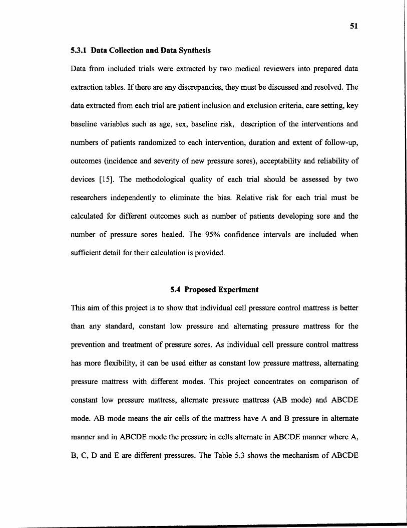
51
5.3.1 Data Collection and Data Synthesis
Data from included trials were extracted by two medical reviewers into prepared data
extraction tables. If there are any discrepancies, they must be discussed and resolved. The
data extracted from each trial are patient inclusion and exclusion criteria, care setting, key
baseline variables such as age, sex, baseline risk, description of the interventions and
numbers of patients randomized to each intervention, duration and extent of follow-up,
outcomes (incidence and severity of new pressure sores), acceptability and reliability of
devices [15]. The methodological quality of each trial should be assessed by two
researchers independently to eliminate the bias. Relative risk for each trial must be
calculated for different outcomes such as number of patients developing sore and the
number of pressure sores healed. The 95% confidence intervals are included when
sufficient detail for their calculation is provided.
5.4 Proposed Experiment
This aim of this project is to show that individual cell pressure control mattress is better
than any standard, constant low pressure and alternating pressure mattress for the
prevention and treatment of pressure sores. As individual cell pressure control mattress
has more flexibility, it can be used either as constant low pressure mattress, alternating
pressure mattress with different modes. This project concentrates on comparison of
constant low pressure mattress, alternate pressure mattress (AB mode) and ABCDE
mode. AB mode means the air cells of the mattress have A and B pressure in alternate
manner and in ABCDE mode the pressure in cells alternate in ABCDE manner where A,
B, C, D and E are different pressures. The Table 5.3 shows the mechanism of ABCDE

52
mode alternating pressure mattress having 18 air cells. As the head portion has three cells
the pressure in these cells is same. Cells 4,9,14 has pressure A, cells 5,10,15 has pressure
B, cells 6,11,16 has pressure C, cells 7,12,17 had pressure D and cells 8,13,18 has
pressure E.
Table 5.3 Mechanism of ABCDE Alternating Pressure Mattress
1. Head2. Head3. Head4. Pressure A5. Pressure B6. Pressure C7. Pressure D8. Pressure E9. Pressure A10. Pressure B11. Pressure C12. Pressure D13. Pressure E14. Pressure A15. Pressure B16. Pressure C17. Pressure D18. Pressure E
The population required for this experiment is SCI and moderate obesity patients
with high risk of developing pressure sores. The inclusion and exclusion criteria should
be mentioned. Patients of any age between 20 to 60 years are included. Gender of the
patient is not taken into consideration for inclusion. As previous studies shows that
clinical judgment is better than any risk assessment scale, clinical judgment should be
used for identifying people at high risk. Risk assessment scale can be used as a
supplement with this. Even previous studies shows that it is not clear which scale is better

53
for assessing risk for developing pressure sores, so any scale can be used but should be
same for all trials. Once the patients are selected, they are randomly allocated to different
air mattress as randomized controlled trials provide better evidences [17]. As this
experiment focuses on prevention of pressure sores, the effect of mattress was assessed
by the presence of at least one pressure sore of stage two or higher as it is a better way of
evaluating air mattress [15]. Incidence rates are used as an indicator of quality of support
surface rather than prevalence rates [17].
For this proposed experiment, mattresses having same cell size should be used for
each group to neglect the effect of cell size and to evaluate the mattresses according to
the sophistication of these mattresses. The main parameter for comparison between
constant low pressure air mattress, AB mode alternating air pressure mattress and
ABCDE mode alternating pressure mattress are range of pressure in air cell, level of
firmness of the mattress. The firmness of mattresses is divided into two parts soft and
firm. Soft firmness means a pressure from 20mmHg to 50mmHG and firm means a
pressure from 50mmhg to 80mmhg. The soft level is further divided into lower range
which is from 20 to 35 mmHg of pressure and higher range from 35mmHg to 50 mmHg
of pressure. Same way firm level is also divided into lower range which is from 50mmHg
to 65mmHg of pressure and higher range from 65mmHg to 80mmHg of pressure. In
order to compare these different groups, 50 patients per each group are selected. Previous
studies show that when there are more patients the outcome gives better results. Previous
studies had selected 20 to 150 patients per each group [17]. Table 4.4 shows the way of
allocating patients into different settings. Hence, for this experiment it required 600
patients either SCI patients or patients with moderate obesity or both.
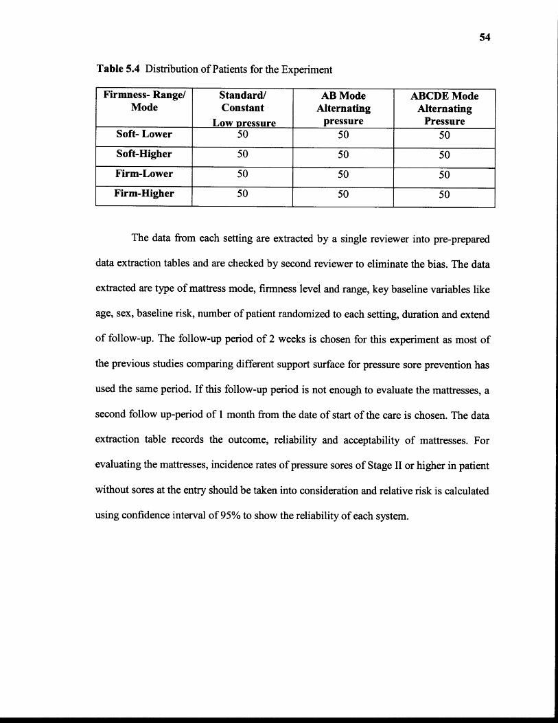
54
Table 5.4 Distribution of Patients for the Experiment
Firmness- Range/Mode
Standard/Constant
Low pressure
AB ModeAlternating
pressure
ABCDE ModeAlternating
PressureSoft- Lower 50 50 50
Soft-Higher 50 50 50
Firm-Lower 50 50 50
Firm-Higher 50 50 50
The data from each setting are extracted by a single reviewer into pre-prepared
data extraction tables and are checked by second reviewer to eliminate the bias. The data
extracted are type of mattress mode, firmness level and range, key baseline variables like
age, sex, baseline risk, number of patient randomized to each setting, duration and extend
of follow-up. The follow-up period of 2 weeks is chosen for this experiment as most of
the previous studies comparing different support surface for pressure sore prevention has
used the same period. If this follow-up period is not enough to evaluate the mattresses, a
second follow up-period of 1 month from the date of start of the care is chosen. The data
extraction table records the outcome, reliability and acceptability of mattresses. For
evaluating the mattresses, incidence rates of pressure sores of Stage II or higher in patient
without sores at the entry should be taken into consideration and relative risk is calculated
using confidence interval of 95% to show the reliability of each system.
CHAPTER 6
HYPOTHESIZED RESULTS AND DISCUSSION
6.1 Results from Comparative Study of the Three Pressure Relieving Surfaces
Application of the proposed experiment requires 600 patients having high risk of
developing pressure sores and all of these 600 patients needs to lie down on the
mattresses for a long period, approximately 2 to 4 months or more. As it is not easy to get
patients and due to time constraints in this project, just a prediction of the results is done
based on previous research. There are several studies done for evaluating support
surfaces for the prevention of pressure sores. Several comparisons were done between
alternating pressure supports and standard/constant low pressure support. Even there are
few studies that compared different types of alternating supports.
6.1.1 Results for Comparison Between AP Mattress and Standard Mattress
The results from one of randomized controlled trial (RCT) from one study comparing
alternating pressure mattress and standard hospital mattress shows that the alternating
pressure support surfaces reduces the incidence of pressure sores as compared with
standard hospital mattress (RR= 0.32; 95% CI, 0.14 to 0.74) [15]. Table 6.1 shows the
results obtained from the comparison of AP mattress and standard mattress when
incidence of pressure of Stage II or greater is considered as a measure of outcome.
55
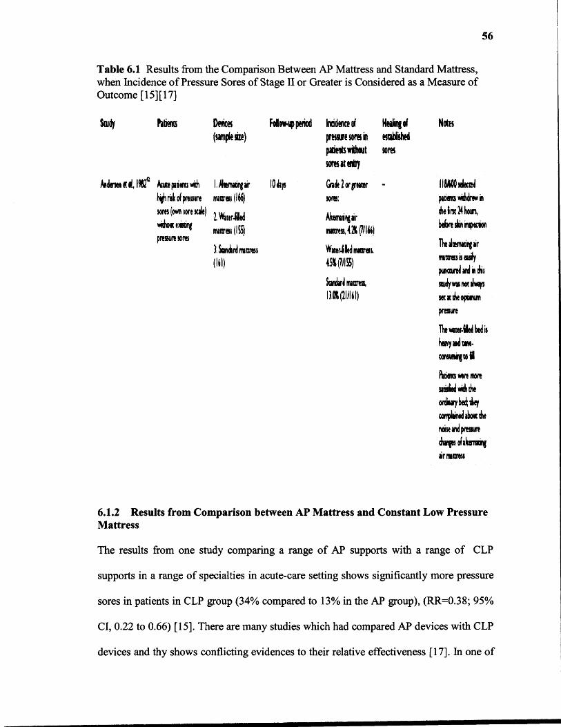
Table 6.1 Results from the Comparison Between AP Mattress and Standard Mattress,when Incidence of Pressure Sores of Stage II or Greater is Considered as a Measure ofOutcome [15] [17]
56
6.1.2 Results from Comparison between AP Mattress and Constant Low PressureMattress
The results from one study comparing a range of AP supports with a range of CLP
supports in a range of specialties in acute-care setting shows significantly more pressure
sores in patients in CLP group (34% compared to 13% in the AP group), (RR=0.38; 95%
CI, 0.22 to 0.66) [15]. There are many studies which had compared AP devices with CLP
devices and thy shows conflicting evidences to their relative effectiveness [17]. In one of
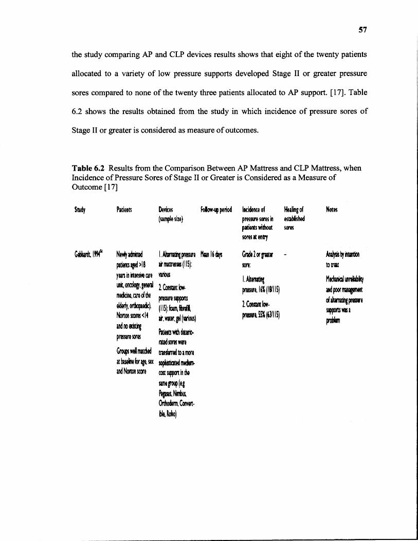
57
the study comparing AP and CLP devices results shows that eight of the twenty patients
allocated to a variety of low pressure supports developed Stage II or greater pressure
sores compared to none of the twenty three patients allocated to AP support. [17]. Table
6.2 shows the results obtained from the study in which incidence of pressure sores of
Stage II or greater is considered as measure of outcomes.
Table 6.2 Results from the Comparison Between AP Mattress and CLP Mattress, whenIncidence of Pressure Sores of Stage II or Greater is Considered as a Measure ofOutcome [17]
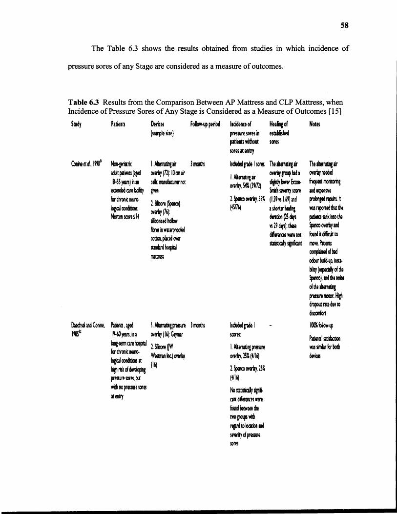
58
The Table 6.3 shows the results obtained from studies in which incidence of
pressure sores of any Stage are considered as a measure of outcomes.
Table 6.3 Results from the Comparison Between AP Mattress and CLP Mattress, whenIncidence of Pressure Sores of Any Stage is Considered as a Measure of Outcomes [15]
59
6.1.3 Results from Comparison Between AB Mode AP Mattress and ABCDEMode AP Mattress
There are several comparisons done between different types of AP mattresses for the
prevention of pressure sores. The depth of the air cells, the mechanical robustness and
sophistication vary between different alternating pressure devices, and these factors may
be important in determining effectiveness [17]. As alternating pressure devices differs in
structures including the size of the inflatable air cells, the results from previous studies
comparing different AP mattresses are unclear [17]. Also previous studies show that, the
trials used to compare different alternating pressure mattresses did not adequately
describe the equipment being evaluated, including the size of the air cells. In this
proposed experiment, mattresses with same cell size are used and hence, the comparison
is solely based on the sophisticated features of the mattresses. The ABCDE mode
mattress has more flexibility in selection of number of chambers to be operated, level of
firmness, range of firmness level, pressure setting in different chambers, than AB mode
mattress. In ABCDE mode AP mattress five different pressures can be set in five
different cells supporting the high pressure intensity portions of the body and hence it
might provide a better pressure relief in high pressure regions. So ABCDE mode has
better resolution in selecting different pressure in different number of cells than AB mode
mattress (i.e., two pressures in AB mattress versus five pressures in ABCDE mattress).
This shows that ABCDE mode mattress has more sophistication than AB mode
AP mattress. Hence, ABCDE mode mattress may be able to provide better options for the
prevention of pressure sores due to presented features, than existing mattresses. But
subject testing is required to validate this belief.
60
6.2 Discussion
In this project, a comparison between standard, alternating pressure (AP) mattress and
individual cell pressure control (ICPC) air mattress is shown. Both AP and ICPC have
more sophisticated features than standard mattresses. Thus, the major comparison is
shown between AP and ICPC mattress. ICPC mattress have better control of pressure as
it uses upper and lower limits of pressures as a reference rather than only one pressure.
This makes the system more stable against the unwanted small changes in pressure due to
little movements of the patient body.
The interface pressure between different parts of the patient's body and different
cells of the air mattress are different. Pressures at the heels, ankles, shoulders, lower
back, buttocks, and head region which are more likely to develop pressure sores in SCI
and moderate obesity patients would be more than the other portions of the body. Also
pressure at the different points in the larger region of the body such as shoulders and
lower back and buttock would not be the same. If an AP mattress is used then these
portions of the body would be exposed to just two different pressure range of the
mattress. If an individual cell pressure control mattress is used then different pressures in
each chamber can be set according to the intensity of the pressure at that particular
chamber. Hence, as the modified system provides more flexibility in selection of
pressures it may have a better pressure relieving property than an AP mattress.
The individual cell pressure control mattress is a closed loop system and AP
mattress is an open loop system. In AP mattress, the system does not respond to any
change in the pressure inside the chamber due to external force or position change of the
patient. This will increase the pressure on the patient body and the risk of developing

61
pressure sores increases. An operator is required to make changes in the settings if the
pressure at any portion of the patient body changes by a remarkable value. But in ICPC
mattress, the system gets feedback. Hence, if the pressure inside the mattress increases
due to an external force or patients position change, it can respond to relieve the
increased pressure either by inflating or deflating the chambers automatically according
to the software settings.
The pressure sensor has a range of around 6mV/10mmHg, which is a very low
resolution and increases quantization error. The output from the voltage offset removal
circuit with a gain of 10 has a range of approximately 60mV/10mmHg. Hence, this
circuit increases range of the output from the pressure sensor and thereby increases
resolution. This leads to the increase in system resolution.
The modified system has a software control rather than a hardware control. The
software used has a good data acquisition capabilities and it is user friendly which makes
the system operation easy. The modified system provides more flexibility by operating in
different mode such as standard, AP or ICPC mattress.
The validity and reliability of the system is checked by measuring the output from
the pressure sensor for different pressures inside the chamber. To know the exact pressure
inside the chamber, a sphygmomanometer is connected to the chamber. The pressure
sensor output (after offset voltage removal and by providing a gain of 10) for 0mmHg to
105mmHg is measured. These values are compared to the theoretical values and
percentage of error is calculated. These obtained outputs values in Volts are taken as a
reference values instead of the pressure in mmHg. These results have an average error of
0.95%.

62
In accuracy test, the system is operated at various levels of action and firmness
and the system is checked by setting different pressure ranges for different chambers.
When the system reaches the preset pressure for each chamber, the output of the pressure
sensor is measured. In addition, the actual pressure hold by the chamber is measured by
sphygmomanometer. The output of the pressure sensor in Volts is converted into mmHg
value and is matched with the sphygmomanometer reading. Percentage of error is
calculated for these outputs. The results show that the system has maximum error of
2.05% when it is operated up to the range of 75mmHG. This shows that the system is
accurate till this range.
The reliability of the system is check by inflating and deflating each chamber for
a particular pressure range for five numbers of times, and each time the output of the
pressure sensor for each pressure range for each chamber is measured. To find the
variability, standard deviation of the outputs obtained for the same chamber and same
pressure range are calculated. Percentage of error is also calculated to show the reliability
of the system. The system has maximum 3.21% of error when the system is operated five
numbers of times which shows that the system is reliable.
The feedback of the system is also checked by the feedback validation test. The
results of this test show that the system has the ability to recover the change in pressure
by using the feedback. The system also neglects the short period impulse of force and it
remains stable. Also, the system has many safety features against total power loss and
leakage in the system.
CHAPTER 7
CONCLUSION
This study is based on improvement of the current assistive technology available to the
SCI and moderate obesity patients suffering from pressure sores. In this study a
comparison between various mattresses and the ICPC mattress is shown to evaluate these
mattresses for the prevention of pressure sores. From the discussion, it has become clear
that ICPC has more sophisticated features than both standard/constant low pressure
mattress and AP mattress. The ICPC mattress has greater flexibility in selecting number
of chambers, pressure range, and firmness level than AP mattress. In ICPC mattress it is
possible to set any pressure range from 0mmHg to 100mHg in any cell, but the system
is checked only up to 75mmHg pressure. The pressure relief quality of the modified
system might be better than AP mattress but patient study is required to validate this
belief.
The engineering data such as the output from the pressure sensor, the results of
the accuracy test, the results from the repeatability test and the results from the system
feedback validation test show that the system is safer, more reliable and more accurate.
The modified system includes additional mechanical components such as directional
control valves and a pump which may requires maintenance or service in long term. But
as individual cell pressure control air mattress is more flexible, it is hypothesized that it
has the more potential to prevent of pressure sores in SCI and moderate obesity patients
having high risk of developing pressure sores. This system is ready for further scientific
study.
63

CHAPTER 8
FUTURE DEVELOPMENTS
The individual cell pressure control air mattress system requires a lot of hardware and
also more space to be installed. Future research is needed to replace a computer and
hardware circuits by a small microcontroller. A PDA version of LabVIEW ® 8 can be
used that is more portable than the current system. Scientific studies can be conducted
using the proposed experiment to evaluate this system for the prevention of pressure
sores in SCI and moderate obesity patients. This system has independent control of each
chamber and it can be operated in different patterns such as wave, pulsation which may
improve the blood circulation and it might have therapeutical benefits, but further
research and patient studies are needed.
64

APPENDIX A
SPECIFICATION AND FEATURES OF THE AP AIR MATTRESS
This appendix describes the features, specifications and structure of the Stimulus Plus
Alternating Pressure Mattress.
65
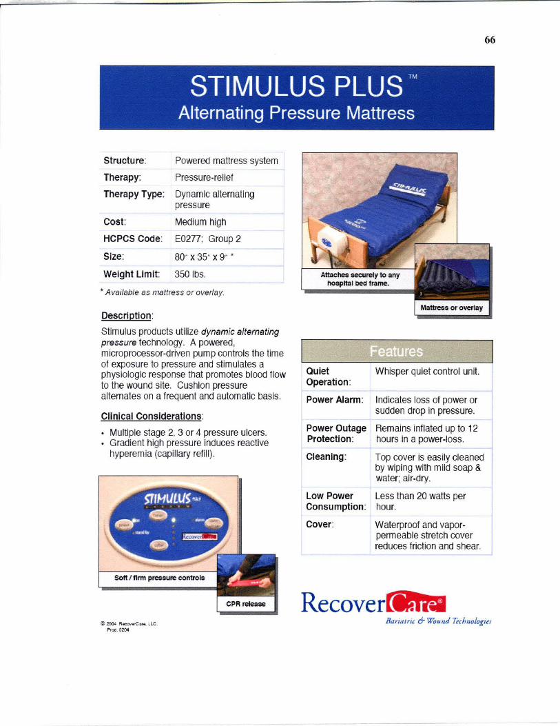
STIMULUS PLUS ™
Alternating Pressure Mattress
Structure:
Therapy:
Therapy Type:
Cost:
HCPCS Code:
Size:
Weight Limit:
Powered mattress system
Pressure-relief
Dynamic alternating pressure
Medium high
E0277; Group 2
80- x 35- x 9- ,
350 1bs .
.. Available as mattress or overlay.
Description:
Stimulus products utilize dynamic alternating pressure technology. A powered, microprocessor-driven pump controls the time of exposure to pressure and stimulates a physiologic response that promotes blood flow to the wound site. Cushion pressure alternates on a frequent and automatic basis.
Clinical Considerations:
Multiple stage 2, 3 or 4 pressure ulcers. Gradient high pressure induces reactive hyperemia (capillary refill).
Soft I firm pressure controls
Quiet Whisper quiet control unit. Operation :
Power Alarm: Indicates loss of power or sudden drop in pressure.
Power Outage Remains inflated up to 12 Protection: hours in a power-loss.
Cleaning: Top cover is easily cleaned by wiping with mild soap & water; ai r-dry.
Low Power Less than 20 watts per Consumption : hour.
Cover: Waterproof and vaporpermeable stretch cover reduces friction and shear.
Recove
66
~ zoo' R«:OIo'r.C:n . • le. BflriaJric 6- Wound 7~cJm%t;~J Proc . 0204

APPENDIX B
SPECIFICATION OF THE PRESSURE SENSOR MPX5100AP
This appendix describes about the specifications of the pressure sensor used in this
project. It shows the data sheet of MPX5100AP pressure sensor. Details such as supply
voltage, operating conditions, range of the pressure and range of output voltage are
described in this appendix.
67
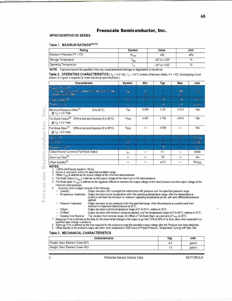
68
Freescale Semiconductor, Inc. MPX5100/MPXV5100 SERIES
Table 1. MAXIMUM RATINGS(NOTE)
Fbting Symbol V31ue Unit
Maximum Pressure (P1 > P2) P",., 400 kPa
Storage Temperature Tstg -40' to +125· 'C
Operating Temperature TA _40 0 to + 1250 ' C
NOTE. Exposure beyond the specified limItS may cause permaoen1 damage or degradation to the de'll CE! .
Table 2. OPERATING CHARACTERISTICS (Ys = 5.0 Vdc. T, = 25'C unless otherwise notec. P1 > P2. Decou~ing cllcuit shovm in Fgure 4 required to meet electrical specifications.)
Differential and Absolute (0 to 85'C) 4.587 4.700 4.8t3 Vde
Differential and Absolute (0 to 85'C) 4.500 Vd,
' , .. . I ~~ . , r. I ""
t r'II " , .. • ;o.; , ~ 0) .. If"- ' l I ." Output Source Current at full Scale Output I .. - 0.1 - mAde
Warm·Up Time(6) - - 20 - ms
Offset Stability(S) - - t 0.5 - %VFSS
NOTES. 1 1.QkPa (kiloPascal) equals 0 145 pSI.
2. Device IS ratiometric WIthin thiS speofied excitation range. l. Offset (Vcr) is defined as the output voltage at the minimum rated pressure d. Full Scale Output (lJfSO) IS defined as the output voltage at the maximum orful! rated pressure. 5. Full Scale ~n (VFSS) is defined as the algebraic difference berween the output voltage at full rated pressure and the output IIOItage at the
mimmJm rated pressure. 6 Accuracy (error budget) consists of the fol lO'Ning'
linearity: Output deVIatIOn from a straight line relationship with pressure over the specrfled pressure range. TemperatUre Hysteresis: Output deviation at any temperature ... :ithin the operating temperature range. after the terrperature is
cycled to and from the minimum or maximum operating te~rature points, with zero differential pressure applied.
Pressure HysteresiS: Output deviation at any pressure wltt'lln the spectfied range. '1,ilen this pressure is cycled to and from mnimum or maximum rated pressure at 25'C.
TcSpan: Output deviation over the temperature range rA O' to 85~C. relative to 25'C. TcOffset Output deviation with mnimum pressure applied, over the ~rature range of O¢ to as'c, relative 10 2S·C. Variation from NOITIInal: The vanation from nominal values, for Offset or Full Scale Span, as a percent of VFSS al 2S"C.
7. Response Time IS defined as the time for lhe incremental change in the output to go from 10% 10 90% of its final value when subjected to a specifted step change In pressure.
8. Warm-up Time is defined as the time required for the product to meet the specified output voltage after the Pressure has been stabilized. 9. Offset Stab:lity is the product's output deVIation ·....nen wbjeded to 1000 hours of Pulsed Pressure. T~ature Cycling WIth Bias Test
Table 3. MECHANICAL CHARACTERISTICS ChOlracteristics Typ Unit
Weight, Ba SIC Element (Case 867) 4.0 grams
Welgh~ BaSIC Element (Case 482) 1.5 grams
2 Motorola Sensor Device Data MOTOROLA

APPENDIX C
SPECIFICATION OF NI DAQ PCI 6024E CARD
This appendix describes about the specifications, operating condition and features of the
data acquisition card PCI 6024E. It shows the data sheet of NI DAQ PCI 6024E.
69

70
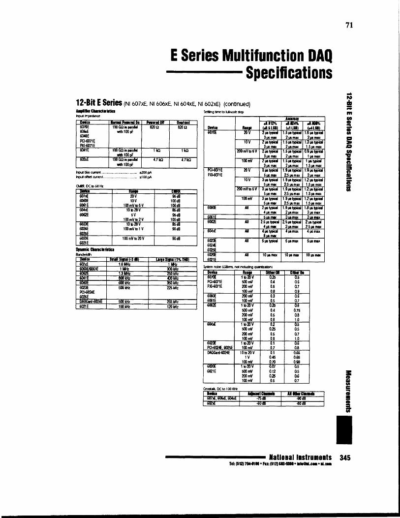
71
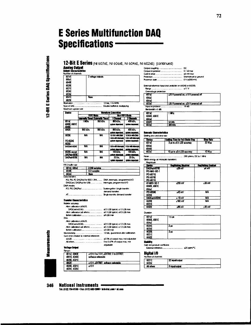
72

73

74

APPENDIX D
PIN ASSISGNMENT OF NI PCI DIO-96 DIGITAL I/O CONNECTOR
This appendix shows the pin assignment for data acquisition card PCI DIO 96 used in
this project.
APC7 1 51 CPC7B PC7 2 52 DPC7APC6 3 53 CPC6BPC6 4 54 DPC6APC5 5 55 CPC5BPC5 6 56 DPC5APC4 7 57 CPC4BPC4 8 58 DPC4APC3 9 59 CPC3B PC3 10 60 DPC3APC2 11 61 CPC2BPC2 12 62 DPC2APC1 13 63 CPC1B PC1 14 64 DPC1A PCO 15 65 CPCOBPCO 16 66 DPCOAPB7 17 67 CPB7BPB7 18 68 DPB7APB6 19 69 CPB6BPB6 20 70 DPB6APBS 21 71 CPB5BPB5 22 72 DPB5APB4 23 73 CPB4BPB4 24 74 DPB4APB3 25 75 CPB3BPB3 26 76 DP33
APB2 27 77 CPS2BPB2 28 78 DPB2APB1 29 79 CPB1BPB1 30 80 DPB1APBO 31 81 CPB0BPBO 32 82 DPBO
APA7 33 83 CPA7BPA7 34 84 DPA7APA6 35 85 CPA6BPA6 36 86 DPA6APA5 37 87 CPA5BPA5 38 88 DPA5APA4 39 69 CPA4BPA4 40 90 DPA4APA3 41 91 CPA3BPA3 42 92 DPA3APA2 43 93 CPA2BPA2 44 94 DPA2APA1 45 95 CPA1BPA1 46 96 DPA1
APAO 47 97 CPAOBPAO 48 98 DPAO+5V 49 99 +5 VGND 50 , 100 GNU
75

APPENDIXE
SPECIFICA nON AND CAD DRAWING OF CONTROL VALVE
This appendix describes the CAD drawing, specifications and features of the directional
control valve used in this project.
1.560
.875
Figure E.' CAD diagram of control valve.
76
16-321hd • • 7/32 _ mounting hoi"
110-321t1d "" .. ,
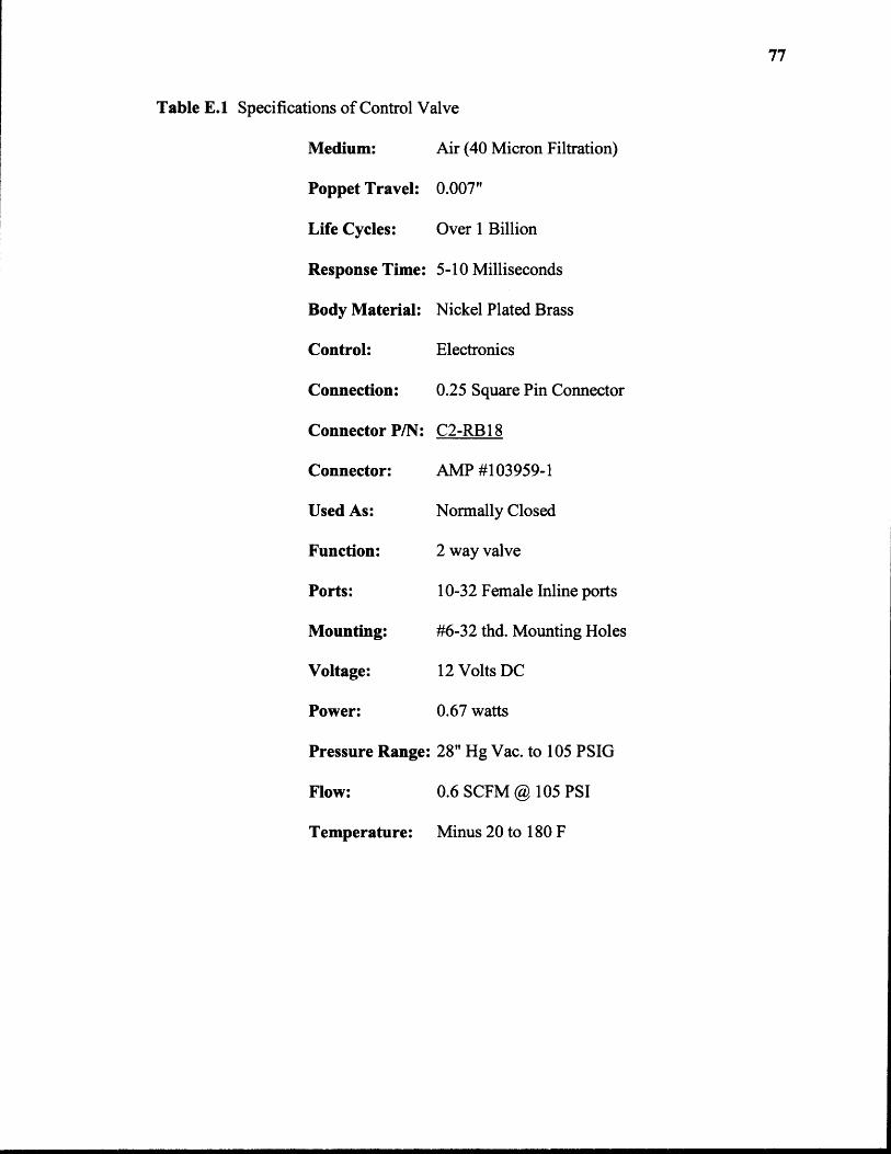
Table E.1 Specifications of Control Valve
77

APPENDIX F
SPECIFICATION OF LM324 OP-AMP
This appendix describes about LM324 IC which is a low power quad op-amp. It is used
In the voltage offset removal circuit. This appendix shows the pin diagram and
specifications of the LM324.
78
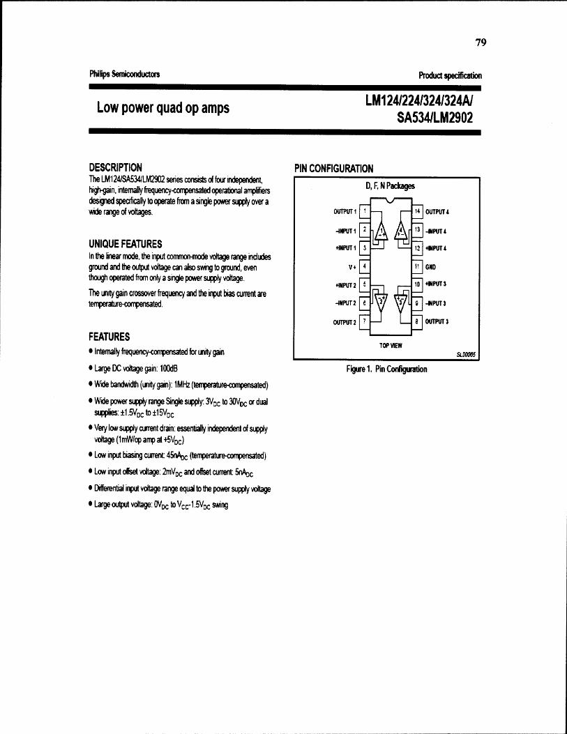
79

APPENDIX G
FRONT PANEL OF THE LABVIEW CODE
This appendix shows the front panel of the LabVIEW code.
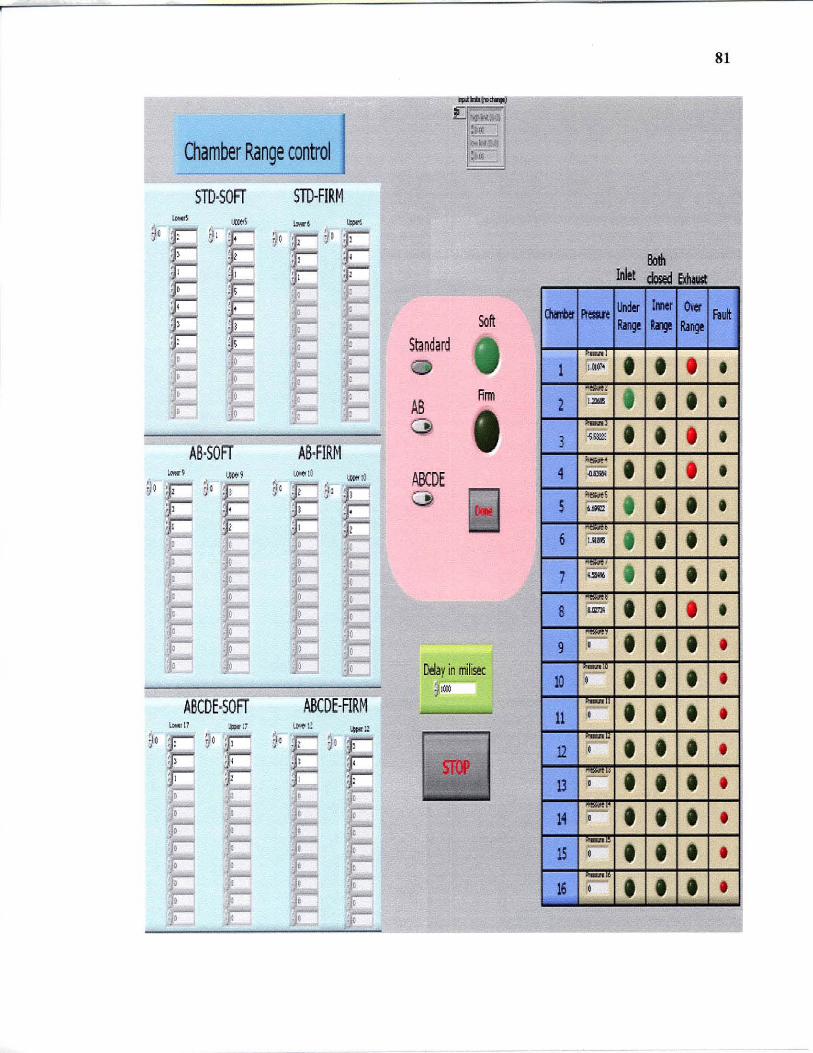
Chamber Range control
STD·SOFr STD-FIRM
""" m.1 .... , ~
90 " Q ~o E% E :: d!
!E '. , ~ I :; E ! I ~ . , l
! I
AB-:sOFr AS·FIRlil -, , ... 1 ""' 10 1A«o !~
yO : I ~a t ~~ • j
, , I C :1 · I
. ; · c
ASCDE·SOFr ABCDE·ARM UM!11 ,,"," ~Ml! ,-"« u
90
~9°E ~o
F ' ~ , I .' , E , : • I , l
Standard
AS (})
ABCDE o
'"'Co_ !l '01'" .,
:aro t
:'oI~ •.
;oc:
Soft
Rrm
Delay in I'rllil« I@
81
1 • 2 • 3 • 4 • 5 • 6 • 7 • 8 • 9 •
10 • 11 •
• • • •
16 ••• •

APPENDIX H
BLOCK DIAGRAM OF THE LABVIEW CODE
This appendix describes about block diagram of the LabVIEW code.
83
~ c=----------------------~
I~--------------------------------~ "
t- -fFi
I
""
REFERENCES
[1] The National Spinal Cord Injury Statistical Center. (2005). Facts and Figures at aglance. http://www.spinalcord.uab.edu/show.asp?durki=21446 (January, 2005).
[2] Spinal Cord Resource Center. http://www.spinalinjury.net/index.html (May, 2005).
[3] Merck & Co., Inc. (2006). Merck Manuals on Effects of Spinal Cord Injury. http://www.merck.com/mmhe/sec06/ch093/ch093a.html#sec06-ch093-ch093a-1239(March, 2006).
[4] Webster, J.G.; "Pressure mat for preventing pressure sores", Proceedings of theAnnual International Conference of the IEEE Engineering in Medicine andBiology Society, 5: 1485-6, 1989.
[5] American Obesity Association. (2005). Obesity Fact Sheet. http://www.obesity.org/subs/fastfacts/aoafactsheets.shtml (March, 2006).
[6] United Spinal Association. (2005). http://www.unitedspinal.org (April, 2006).
[7] Linder-Ganz, E., Gefen, A.; "Stiffening of muscle tissue under bone compression isa key factor in formation of pressure sores", Proceedings of the 25th AnnualInternational Conference of the IEEE Engineering in Medicine and BiologySociety, 2(2): 1839-42, 2003.
[8] Tallahassee Memorial Would Healing Center. (2005). Symptoms of Pressure Sores.http ://www.tmh.org/body.cfrn?id=223&action=detail&AEProductIlD=HW_Knowledgebase&AEArticleID=tp17772&#tp17774 (January, 2006).
[9] Spinal Cord Injury Information Pages. (2006). Skin and Pressure Sore Treatment andPrevention after Spinal Cord Injury, http://www.sci-info-pages.com/skinpres2 .html (April, 2006).
[10] Mayo Foundation for Medical Education and Research. (2006). Bedsores. http://www.mayoclinic.com/health/bedsores/DS00570 (March, 2006).
[11] Disabled Living Foundation. (2006). Choosing a Pressure Relief Equipment. www.dlf. org.uk/factsheets/pdf/Choosingpressure_relief equipment.pdf (May, 2006).
[12] Freescale Semiconductor, Inc. (2005). Data Sheet of Pressure Sensor MPX5100AP.http://www.freescale.corn/files/sensors/doc/data_sheet/MPX5100.pdf (February,2006).
[13] National Instruments Co., Inc. (2005). E series Multifunction DAQ. http://sine.ni .com/apps/we/nioc.vp (April 2006).

85
[14] National Instruments Co., Inc. (2005). Datasheet of PCI DIO 96 DAQ card. http://www.ni.com/pdf/products/us/4daqsc379-384_374-376.pdf (April 2006).
[15] Cullum N, Nelson EA, Flemming K, Sheldon T. Systematic reviews of wound caremanagement: (5) beds; (6) compression; (7) laser therapy, therapeutic ultrasound,electrotherapy and electromagnetic therapy. Health Technology Assess, 5(9),2001.
[16] S. Sterzi, G. Selvaggi, A. Romanelli, P. Valente, C. Bertolini. Eur J Plast Surg.Evaluation of prevalence and incidence of pressure ulcers and their relationshipwith mattresses used in a general hospital intensive care unit, 25: 401-404, 2003.
[17] Prevention and Treatment of Pressure Sores. Effective healthcare bulletin on theeffectiveness of health service interventions for the decision makers. NuffieldInstitute for Health, University of Leeds, NHS centre for reviews anddissemination, University of York, 2(1), October 1995.
[18] Charlifue SL, Lammertse DP, Adkins RH. Aging with spinal cord injury: Changes inselected health indices and life satisfaction. Arch Phys Med Rehabilitation, 85(11): 1848-53, 2004.