Embed Size (px)
Citation preview

Copyright Joseph Greene 2001 1
Reinforcements
Professor Joe Greene
CSU, CHICO

Copyright Joseph Greene 2001 2
Reinforcements
• Fiber Reinforcements
• Glass Fibers
• Carbon/Graphite Fibers
• Organic Fibers
• Boron, Silicon Carbide, and Specialty Reinforcements
• Fabrics and Other Reinforcement Forms
• Particle and Whisker Reinforcements
• Reinforcement/Matrix Interactions
• Comparisons of Reinforcements

Copyright Joseph Greene 2001 3
Objectives • Understand the differences and similarities in major
types of reinforcements used in composite structures
• Identify the principal uses for each of the major types of reinforcements.
• Discuss the principal methods for manufacturing reinforcements
• Compare the different types of reinforcement forms and evaluate their relative merits.
Copyright Joseph Greene 2001 4
Fiber Reinforcements• Reinforcements for composites can be
– Fibers, Particles, or whiskers– Each has its own unique applications, although fibers are the most
common in composites.– Particles and whiskers improve slightly the stiffness (modulus) and
reduce the CLTE of the base resin, but decrease the strength and impact.
• Fibers are materials that have one very long axis compared to others and is characterized by the aspect ratio (fiber length divided by fiber diameter)– Length of short fiber = 3 mm, diameter = 12.7 microns (10-6 m)– Length of long fiber = 6 mm, diameter = 10 microns (10-6 m)– Aspect ratio = 3/12.7 x 1000– Fibers are stronger in the length direction than in the cross direction
Copyright Joseph Greene 2001 5
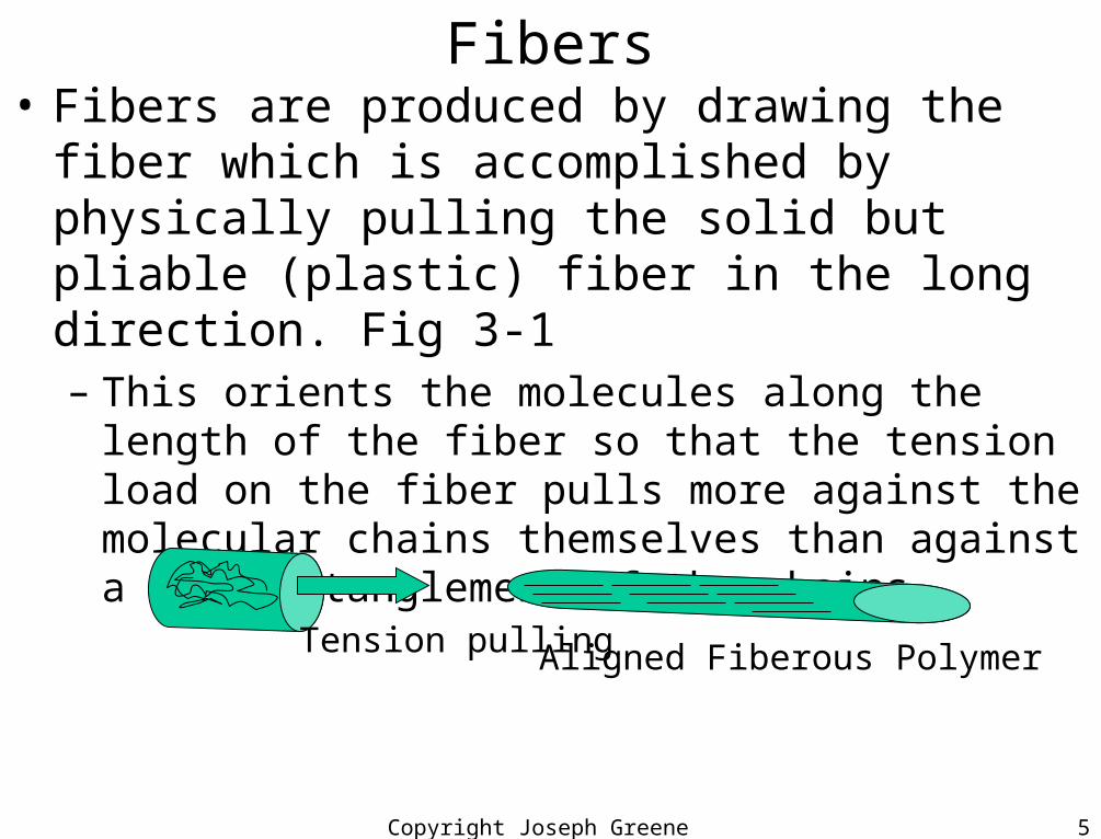
Fibers• Fibers are produced by drawing the fiber which is
accomplished by physically pulling the solid but pliable (plastic) fiber in the long direction. Fig 3-1– This orients the molecules along the length of the fiber so
that the tension load on the fiber pulls more against the molecular chains themselves than against a mere entanglement of the chains.
Tension pulling Aligned Fiberous Polymer
Copyright Joseph Greene 2001 6
Fibers• Fibers are available as Continuous or Discontinuous
– Continuous can be in a variety of weaves, woven, mats, etc.– Discontinuous can be chopped into lengths from 3mm, 6mm
12mm, and up to 25mm
• Particles have no preferred orientation and have an irregular shape. Used to reduce cost, shrinkage, CLTE

Copyright Joseph Greene 2001 7
Glass Fibers• Fiber reinforcements have been known and used for centuries.
• Renaissance Venetian artisans incorporated glass strands in crossed or web-like configurations to strengthen their fine, thin walled glass objects, e.g., vases, etc..
• Glass manufacturing process• Raw materials are silica (SiO2), sand, limestone, boric acid, and other minor
ingredients (e.g., clay, coal, fluorospar)• Materials are dry mixed and melted in a high temperature refractory furnace.
Temp is about 2300F (1260C)
– Two processes• Marble process where the glass ingredients are shaped into marbles, sorted by
quality, and then remelted into fiber strands• Alternatively, the molten glass is introduced directly to fiber strands.
– The glass melt flows through formation bushings and then air cooled• Continuous strands are called filaments. Diameter is controlled by hole size,
draw speed, temperature, viscosity of melt, and cooling rate.• Protective coating or SIZING is applied so that the fibers pass through the
mechanical equipment without breaking.• Fibers are elongated or drawn and then wound up in rolls or tows.
Copyright Joseph Greene 2001 8
Glass Fibers• Types of glass fibers
– Glass is an amorphous material that consists of a silica (SiO2) backbone with various oxide components to give specific compositions and properties.
– Several glass fibers can be produced, but only 4 are used. Table 3-1• E-glass: electrical glass
– Ca aluminoborosilicate composition with max 2% alkali– Most common glass for composites and used when strength and high
electrical resitivity. Lowest cost glass• S-glass: high strength glass and S2
– 40% higher strength and better property retention at high temp– Used in advanced composites and aerospace applications
• C-glass: chemical resistant glass– Has soda-lime borosilicate composition and due to its chemical stability is
used in corrosive environments• Quartz:
– Used for electrical applications where a low dielectric material is required, e.g., antennas and in radomes

Copyright Joseph Greene 2001 9
Glass Fibers• Properties of Glass Fibers: (Table 3-1)
Type of GlassProperty C E SDensity 2.49 2.54 2.48Tensile Strength, ksi 460 500 665
Tensile Modulus, Msi 10 10.5 12.4CLTE (in/in/ F) x10-6 4 2.8 3.1Specific Heat @72F 0.2 0.195 0.176Softening Point, F 1381 1550 1778Dielectric Constant 0.008 0.002 0.003Chemical Resistance (% wt gain after 24hrs)In H20 1.1 0.7 0.7In 10%HCl 4.1 4.2 3.8In 10% H2SO4 2.2 3.9 4.1In 10% Na2CO3 2.4 2.1 2
Copyright Joseph Greene 2001 10
Glass Fibers Surface Treatments• Surface Treatments
– Glass fibers are extremely fragile and abrade easily• Especially apparent when fibers are weaved
– Chemical coating (sizing) is added to protect the fibers and holds the individual filaments together.
• Usually the sizing agent is temporary and a finish (PVAc with organo-silane coupling is added after the size is removed
– The sizing agent (size) can be a finish as well.– Coupling agent are molecules
• One end that is compatible with the silane structure of the glass • The other is compatible with the matrix resin.• Different coupling agents can change strength values 100%
– Antistatic agents and lubricants can be added to match the desired use of glass as a chopped glass or woven mat.
Copyright Joseph Greene 2001 11
Glass Fiber Applications• Discontinuous (Chopped) Fiber
• Short fiber (L= 3mm) reinforcement for thermoplastic materials that are injection molded (PP and Nylon)
• Long Fiber (L=6mm) reinforcement for thermoplastic materials that are injection molded (Nylon)
• Chopped Fiber (L=12 mm to 25 mm) reinforcement for thermoset (SMC and BMC) and thermoplastic BMC that are compression molded into parts for Corvette hoods and doors, bumpers, Ford Truck box, and consumer box shapes
• Continuous (Mat) Fiber– Many types of weaves for automotive or aerospace
applications• Automotive: Viper hood with RTM, GM Truck box with SRIM,
Corvette floor pan with RTM• Aerospace: Prepregs, Wings, Fuselages with RTM and SCRIMP
Copyright Joseph Greene 2001 12
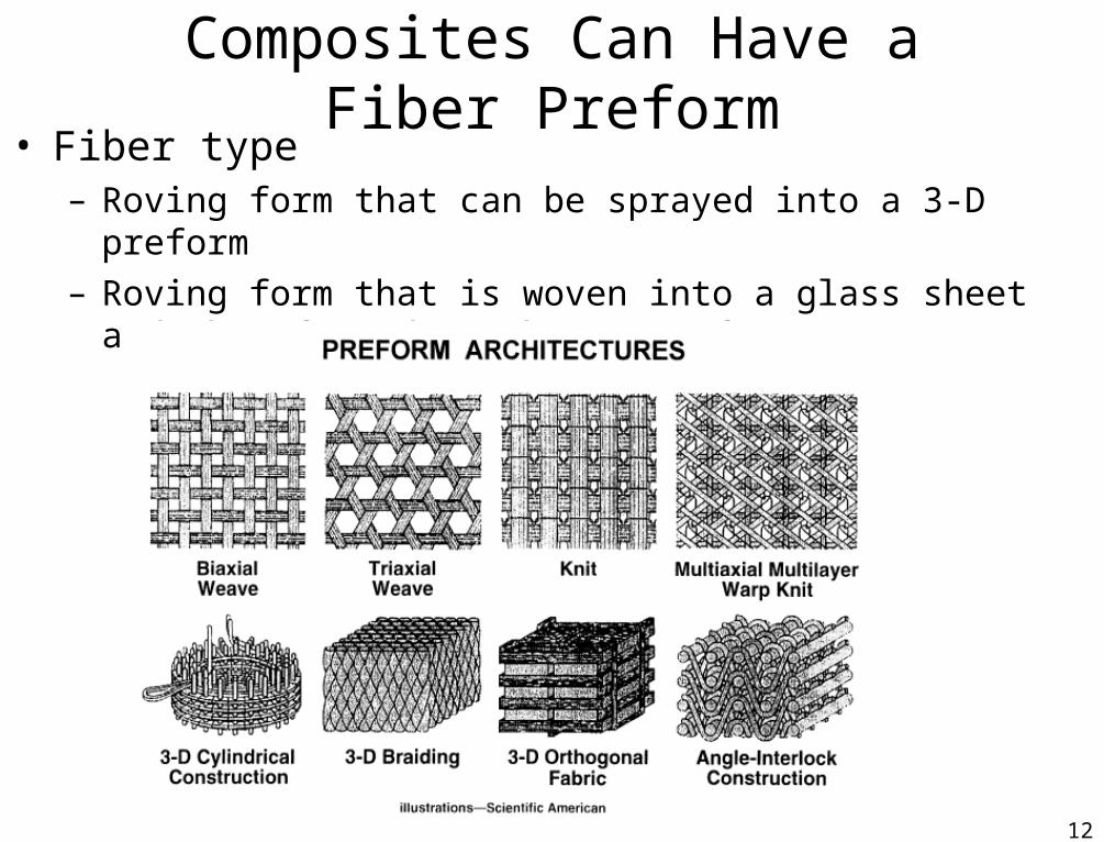
Composites Can Have a Fiber Preform• Fiber type
– Roving form that can be sprayed into a 3-D preform
– Roving form that is woven into a glass sheet and then formed to shape (preform)
Copyright Joseph Greene 2001 13
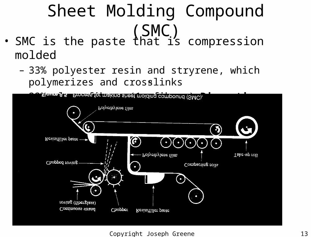
Sheet Molding Compound (SMC)• SMC is the paste that is compression molded
– 33% polyester resin and stryrene, which polymerizes and crosslinks
– 33% glass fibers (1” fibers) Discontinuous fiber
– 33% Calcium Carbonate
Copyright Joseph Greene 2001 14
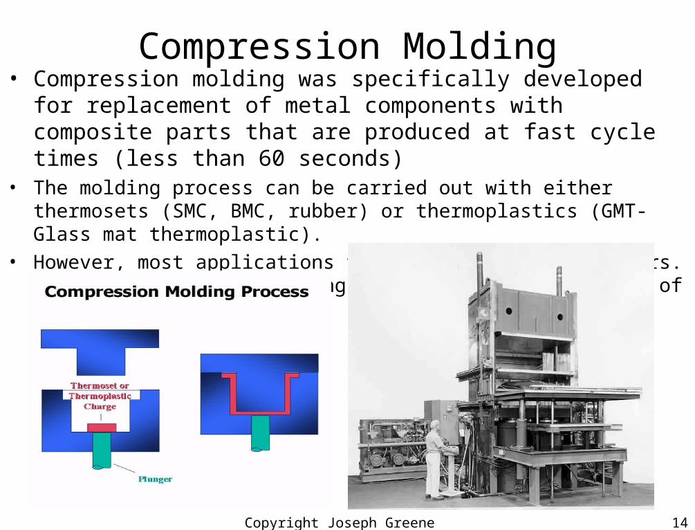
Compression Molding• Compression molding was specifically developed for replacement of
metal components with composite parts that are produced at fast cycle times (less than 60 seconds)
• The molding process can be carried out with either thermosets (SMC, BMC, rubber) or thermoplastics (GMT- Glass mat thermoplastic).
• However, most applications today use thermoset polymers. In fact,compression molding is the most common method of processing thermosets.

Copyright Joseph Greene 2001 15
Glass Preform Processing for Composites• Discontinuous Glass Preforms
– Spray-up of 3-D preform
• Continuous fiber– Filament winding
Copyright Joseph Greene 2001 16
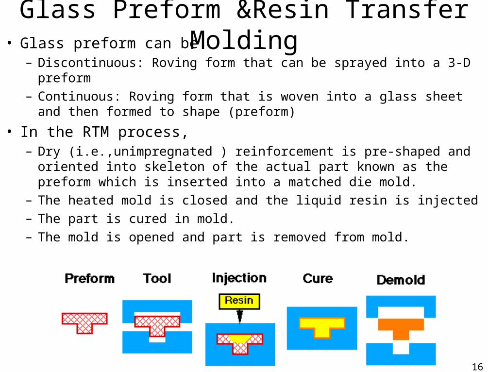
Glass Preform &Resin Transfer Molding• Glass preform can be
– Discontinuous: Roving form that can be sprayed into a 3-D preform– Continuous: Roving form that is woven into a glass sheet and then formed
to shape (preform)
• In the RTM process, – Dry (i.e.,unimpregnated ) reinforcement is pre-shaped and oriented into
skeleton of the actual part known as the preform which is inserted into a matched die mold.
– The heated mold is closed and the liquid resin is injected– The part is cured in mold.– The mold is opened and part is removed from mold.
Copyright Joseph Greene 2001 17
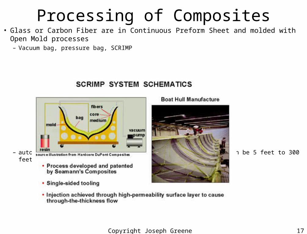
Processing of Composites• Glass or Carbon Fiber are in Continuous Preform Sheet and molded with Open Mold
processes– Vacuum bag, pressure bag, SCRIMP
– autoclave: Apply Vacuum Pressure and Heat in an oven which can be 5 feet to 300 feet long

Copyright Joseph Greene 2001 18
Properties of Materials • Tensile modulus Density Spec Mod
– Low alloy steel 207GPa(30Mpsi) 7.85 g/cc 26spGPa
– Aluminum 72GPa (10Mpsi) 2.8 g/cc 26spGPa
– Carbon fiber 300GPa(40Mpsi) 1.8 g/cc 167spGPa
– Glass fiber 76GPa (10Mpsi) 2.56g/cc 30spGPa
– Aramid fiber 125GPa (20Mpsi) 1.4g/cc 89spGPa
(Kevlar)
• Tensile strength Density Spec Str– Low alloy steel 1500MPa(220Kpsi) 7.85 g/cc 191spMPa
– Aluminum 500MPa(75Kpsi) 2.8 g/cc 178spGPa
– Carbon fiber 2400MPa(360Kpsi) 1.8 g/cc 4320spGPa
– Glass fiber 2000MPa(300Kpsi) 2.56g/cc 781spGPa
– Aramid fiber 3000MPa (450Kpsi) 1.4g/cc 2140spGPa
(Kevlar)

Copyright Joseph Greene 2001 19
Automotive Plastics and Composites Use
• Exterior Composite Panels– doors
• Sheet Molded Compound (SMC) with compression molding: Camaro, Firebird and Corvette• Polyester resin and glass mat preform with Resin Transfer Molding (RTM): Viper
– hoods• Sheet Molded Compound (SMC) with compression molding: Camaro, Firebird, Corvette, Ford trucks• Polyester resin and glass mat preform with Resin Transfer Molding (RTM): Viper, Heavy duty trucks)
– bumper beams• Glass Mat Thermoplastic (GMT) with compression molding : Camaro, Firebird, Venture, Transport,
• Interior– floor pan
• Polyester resin and glass mat preform with Resin Transfer Molding (RTM): Corvette
• Engine– Sheet Molded Compound (SMC) with compression molding: valve covers, intake manifolds,
fluid containers, etc.

Copyright Joseph Greene 2001 20
8-25-98 M41_au25 5
Automotive Applications ofPlastics and Composites
n Composite Intensive Vehicles
SMCSheet Molding Compound: Polyester Resin and chopped glass Polyester resin and Glass Mat Preform
With RTM Resin Transfer Molding
Copyright Joseph Greene 2001 21
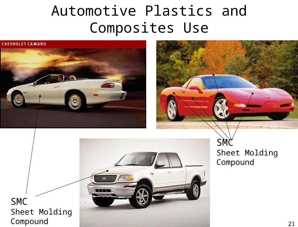
Automotive Plastics and Composites Use
SMCSheet Molding Compound
SMCSheet Molding Compound
Copyright Joseph Greene 2001 22
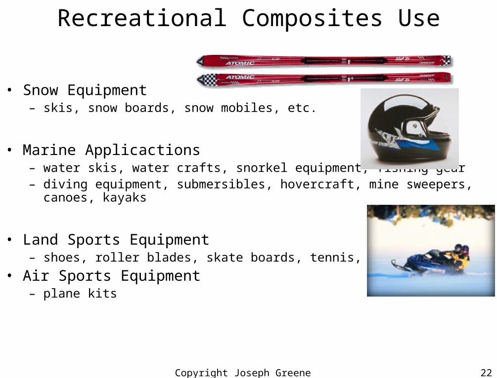
Recreational Composites Use
• Snow Equipment– skis, snow boards, snow mobiles, etc.
• Marine Applicactions– water skis, water crafts, snorkel equipment, fishing gear– diving equipment, submersibles, hovercraft, mine sweepers, canoes, kayaks
• Land Sports Equipment– shoes, roller blades, skate boards, tennis, golf
• Air Sports Equipment– plane kits

Copyright Joseph Greene 2001 23
Carbon/Graphite Fibers
• Need for reinforcement fibers with strength and modulii higher than those of glass fibers has led to development of carbon
• Thomas Edison used carbon fibers as a filament for electric light bulb
• High modulus carbon fibers first used in the 1950s• Carbon and graphite are based on layered structures of
hexagonal rings of carbon• Graphite fibers are carbon fibers that
– Have been heat treated to above 3000°F that causes 3 dimensional ordering of the atoms and
– Have carbon contents GREATER than 99%
– Have tensile modulus of 344 Gpa (50Mpsi)
Copyright Joseph Greene 2001 24
Carbon/Graphite Fibers
• Manufacturing Process– Current preferred methods of producing carbon fibers are from
polyacrylonitrile (PAN), rayon (regenerated cellulose), and pitch.
• PAN– Have good properties with a low cost for the standard modulus carbon
– High modulus carbon is higher in cost because high temperatures required
• PITCH– Lower in cost than PAN fibers but can not reach properties of PAN
– Some Pitch based fibers have ultra high modulus (725 GPa versus 350GPa) but low strength and high cost (Table 3-2)

Copyright Joseph Greene 2001 25
Carbon/Graphite Fibers• PAN Manufacturing Process Figures 3-3 and 3-4
– Polyacrylonitrile (PAN) is commercially available textile fiber and is a ready made starting material for PAN-based carbon fibers
– Stabilized by thermosetting (crosslinking) so that the polymers do not melt in subsequent processing steps. PAN fibers are stretched as well
– Carbonize: Fibers are pyrolyzed until transformed into all-carbon• Heated fibers 1800°F yields PAN fibers at 94% carbon and 6% nitrogen• Heated to 2300°F to remove nitrogen yields carbon at 99.7% Carbon
– Graphitize: Carried out at temperatures greater than 3200° F to• Improve tensile modulus by improving crystalline structure and three
dimensional nature of the structure.
– Fibers are surface treated• Sizing agent is applied• Finish is applied• Coupling agent is applied
– Fibers are wound up for shipment

Copyright Joseph Greene 2001 26
Carbon/Graphite Fibers
• PITCH Manufacturing Process Figure 3-3– Pitch must be converted into a suitable fiber from petroleum tar
• Pitch is converted to a fiber by going through a meso-phase where the polymer chains are somewhat oriented though is a liquid state (liquid crystal phase)
• Orientation is responsible for the ease of consolidation of pitch into carbon
– Stabilized by thermosetting (crosslinking) so that the polymers do not melt in subsequent processing steps
– Carbonize: Fibers are pyrolyzed until transformed into all-carbon• Heated fibers 1800°F
• Heated to 2300°F
– Graphitize: Carried out at temperatures greater than 3200° F to• Improve tensile modulus by improving crystalline structure and three dimensional nature
of the structure.
– Fibers are surface treated• Sizing agent is applied
• Finish is applied
• Coupling agent is applied
– Fibers are wound up for shipment
Copyright Joseph Greene 2001 27
Carbon Fiber Mechanical Properties
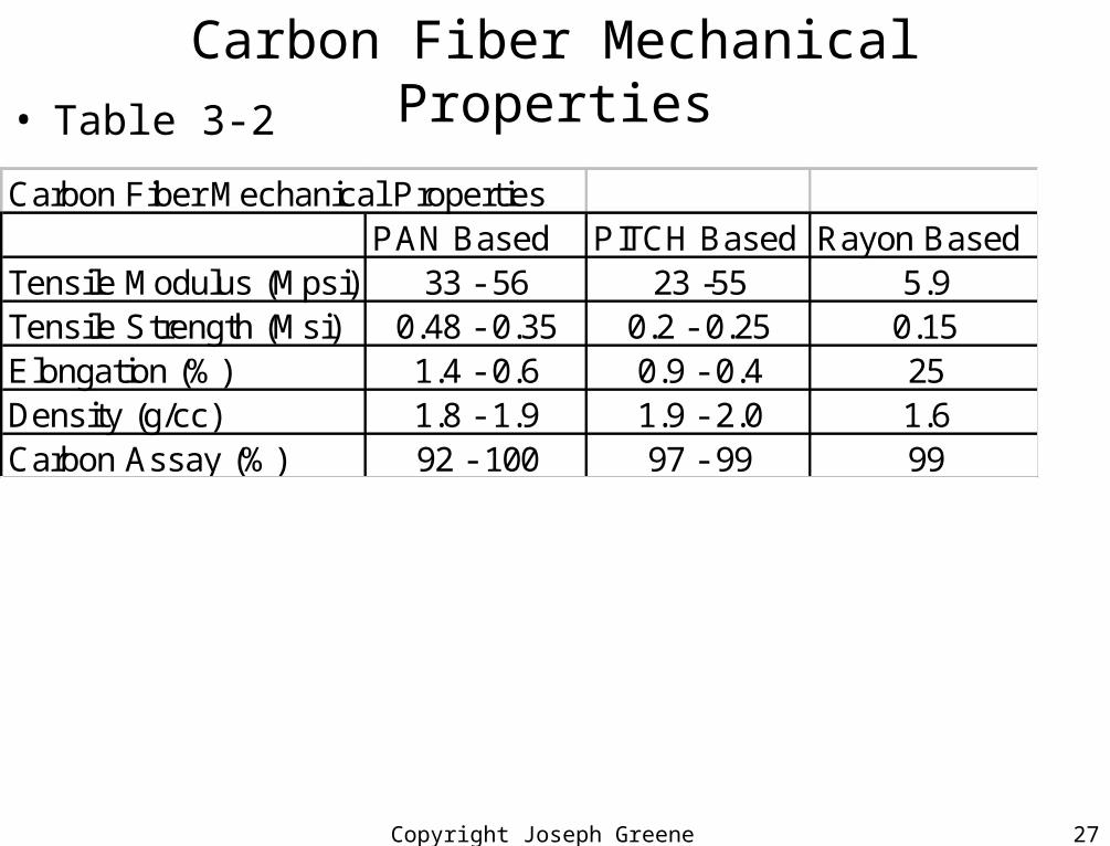
• Table 3-2
Carbon Fiber Mechanical PropertiesPAN Based PITCH Based Rayon Based
Tensile Modulus (Mpsi) 33 - 56 23 -55 5.9Tensile Strength (Msi) 0.48 - 0.35 0.2 - 0.25 0.15Elongation (%) 1.4 - 0.6 0.9 - 0.4 25Density (g/cc) 1.8 - 1.9 1.9 - 2.0 1.6Carbon Assay (%) 92 - 100 97 - 99 99

Copyright Joseph Greene 2001 28
Carbon Fiber Surface Treatments• Surface Treatments– Early disadvantage of carbon fiber was the low interlaminar shear strength
(ILSS) and lower than for glass or boron fibers.– ILSS is a shear strength that assumes that the shear occurs between two
laminates• A laminate is a layer of the composites that is made from resin impregnating a layer of
reinforcement.
– Improvements in the elastic (Young’s) modulus by treating the carbon fibers at higher temperatures resulted in a lower ILSS values.
• Low values = poor bonding between the carbon fiber and the matrix resin.
– Surface treatments are needed to improve the fiber/matrix interfacial bonding and consequently the ILSS
– Oxidative surface treatments using liquid phase and not gaseous phase• Drawing the fibers through a bath of some convenient oxidizing agent
– nitric acid, potassium peranganate, sodium hypochlorite
• Drawing the fibers through an acidic or alkaline electrolytic bath (preferred)
• Result of oxidation is to clean the carbon surface and then to attach chemical groups, hydroxides, which can bond with the matrix or sizing agent
Copyright Joseph Greene 2001 29
Carbon Fiber Surface Treatments• Surface treatment
– Organic coatings (sizes) are added to the fibers in some cases to improve the fiber/matrix bonding & protect the fibers during processing
– Sizes are applied to both treated and untreated fibers by passing the fibers through a heated bath of sizing agent.
• Epoxy is most common, but PVOH and polyimides have been used.
• Not as critical as in glass fibers due to carbon fiber’s better moisture resistance.
• Dilemma: Properties of carbon fiber: Table 3-2– Dilemma- if high modulus for PAN is desired then strength is sacrificed.
• Due to scaly or onion-skin surface develops as the fiber is treated to increase modulus, which worsens the fiber-matrix bonding.
– Tensile modulus and tensile strength are determined by using either a single fiber or a strand of fiber filaments.
• Statistical methods are used because of erratic data from single fibers
• Testing conditions and processing parameters affect properties,
– Length of fiber specimen increases then more flaws are possible in the fiber and reducing strength. Not affected by strain rate or testing temperature.
– Heat treatment temperature, time, stretch, type of precursor, surface treatment
Copyright Joseph Greene 2001 30
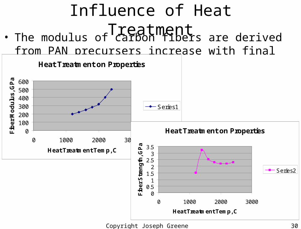
Influence of Heat Treatment• The modulus of carbon fibers are derived from PAN precursers
increase with final heat treatment. Heat Treatment on Properties
0100200300400500600
0 1000 2000 3000
Heat Treatment Temp, C
Fib
er
Mo
du
lus
, GP
a
Series1
Heat Treatment on Properties
00.5
11.5
22.5
33.5
0 1000 2000 3000
Heat Treatment Temp, C
Fib
er
Str
en
gth
, GP
a
Series2
Copyright Joseph Greene 2001 31
Carbon Fiber Properties• Carbon Fibers are good conductors of electricity
– Due o natural conductivity of graphite and the orientation of the graphene rings which lie parallel to the axis of the fiber.
– Considerable research is underway to improve the conductivity of carbon fibers.
• Carbon fibers have very low CLTE, slightly negative (contract upon heat)– CLTE becomes more negative with increasing modulus. The contraction can be
combined with a positive CLTE of a polymer matrix to have a net zero CLTE.
• Mechanical Properties– Ideal engineering material would have high strength, high stiffness, high toughness,
and low weight.– Carbon fibers combined with polymer matrices meet these criteria more closely than
any other material– Carbon fibers are
• Elastic to failure at normal temperatures• Creep resistant and nonsusceptible to failure.• Chemically inert except in strong oxidizing environments or in contact with
certain molten metals.• Excellent damping characteristics.
Copyright Joseph Greene 2001 32
Carbon Fiber Applications• Disadvantages of Carbon Fibers
– Brittle and low-impact resistance, – Low break extensions (low strain to failure),– Low compressive strengths and small CLTE– Expensive compared to glass fibers
• Applications– Aircraft control surfaces- wing spoilers, flaps, elevators, rudders– Helicopter rotor blades and aircraft landing gear and doors,– Transportable bridges – Automotive drive shafts and leaf springs and structural beams– Sporting goods: golf clubs, tennis racquets, fishing rods, skis, frames– Racing car bodies, spacecraft, rockets, missiles– Thermal applications
• Heat shields for missiles and rockets • Aircraft brakes and aerospace antennas and space telescope platforms

Copyright Joseph Greene 2001 33
Carbon Fiber Applications• Applications
– Chemical inertness• Storage tanks and nuclear industry parts
– Rigidity and good dampening• Musical instruments and audio speakers
– Electrical conductivity• Shield against radio frequency interference (not s good as metal)
• Touch switches
– Biological inertness and x-ray permeability• Artificial joints, heart valve components, and X-ray equipment
– Fatigue resistance and self-lubrication• Textile machine components, air slide valves, compressor blades, and artificial
limbs

Copyright Joseph Greene 2001 34
Organic Fiber• Most common organic fiber used for reinforcement
– Aramids, with Kevlar, a DuPont fiber as a major brand– Other aramids– Ultra high orientation polyethylene fiber (Spectra)
• Aramid– Introduced in 1971 in commercial products.– Used for reinforcements for tires, belts, and other rubber-related
goods– Bullet proof vests, high strength cloth, sails for racing boats.
• Manufacturing Process– Para-phenylene diamine and terphthaloyl chloride are mixed in an
organic solvent to form Para-phenylene-tere-phthalamide (Aramid)• Fig 3-5 is the chemical reaction- condensation reaction• Highly aromatic nature of polymer gives good thermal and strength properties
and linear nature of the bonding and hydrogen bonding gives good rigidity.

Copyright Joseph Greene 2001 35
Organic Fiber- Kevlar• Manufacturing Process
– Para-phenylene-tere-phthalamide (Aramid)• Polymer is washed and then dissolved in sulfuric acid
– Polymer is partially oriented, liquid crystal form.• Polymer solution is extruded through small die holes (spinnerettes in a process know
as solution spinning.– Spinning is the name given to the formation of a fiber and can be one from
either a solution or a melt of the polymer• Fibers are then washed and dried and wound up.
– Note: The fibers are not drawn to increase orientation of the molecules, unlike normal textile fibers and glass fibers.
• Aramid fibers are oriented in the solution and during spinning are further orientated as it passes through the spinnerette
– No surface treatment is applied as with caron fibers.– A finish or size (usually epoxy) is applied for many applications,
especially for weaving, making rope, and ballistic reasons, though not for composites
– Bundles of filaments range from 134 to 10,000 filaments per bundle.

Copyright Joseph Greene 2001 36
Organic Fiber- Kevlar Properties• Properties- Table 3-3
– Kevlar is made is three types• Kevlar 29 (high toughness)• Kevlar 49 (high modulus), and• Kevlar 149 (ultra-high modulus)
– Property difference is due to changes in process conditions which promote additional crystallinity in the high modulus and ultra modulus
– Tensile strength and modulus of aramids are much higher than other organic fibers, though not as high as carbon fibers.
– Aramid fibers are less brittle than carbon or glass fibers– Failure mode of aramid fibers is breakage into small fibrils which are like
fibers within the fibers.• Tensile failure initiates at the end of the fibrils and is propogated by shear through the
fiber.• The provides very high tensile strengths for aramid composites, but low compression
strengths which are 50% of carbon fiber composites
– Aramid fibers are flame resistant and resistant to most solvents except strong acids and bases.
Copyright Joseph Greene 2001 37
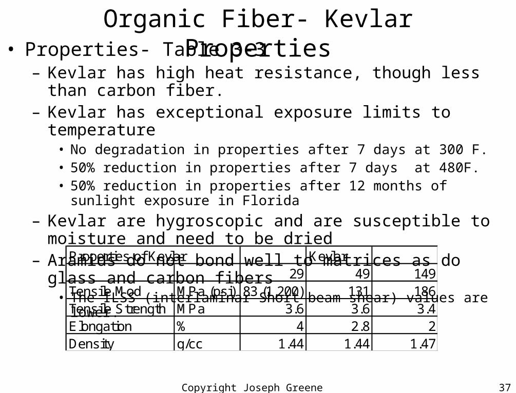
Organic Fiber- Kevlar Properties• Properties- Table 3-3
– Kevlar has high heat resistance, though less than carbon fiber.– Kevlar has exceptional exposure limits to temperature
• No degradation in properties after 7 days at 300 F.• 50% reduction in properties after 7 days at 480F.• 50% reduction in properties after 12 months of sunlight exposure in Florida
– Kevlar are hygroscopic and are susceptible to moisture and need to be dried
– Aramids do not bond well to matrices as do glass and carbon fibers• The ILSS (interlaminar Short beam shear) values are lower.
Properties of Kevlar Kevlar29 49 149
Tensile Mod MPa (psi) 83 (1,200) 131 186Tensile Strength MPa 3.6 3.6 3.4Elongation % 4 2.8 2Density g/cc 1.44 1.44 1.47
Copyright Joseph Greene 2001 38
Organic Fiber- Kevlar Uses• Uses of Aramid Fiber
– Bullet proof vests, armor for ships and motorized combat vehicles.– Battlefield shelters because of good antiballistic properties
• Slippage that occurs between the matrix and the fiber which is enhanced by sizing the fibers.
– Leading edges of wings and other structures where impact damage might be expected.
– Pressure vessels
• Ultrahigh orientation polyethylene fibers– PE fiber that has excellent strength to weight and modulus fibers
• Allied Corp, Spectra
– Approximately the same strength and modulus as Aramid– Higher specific modulus and strength due to low density– Solvent resistant superior to aramid– Thermal resistance is less than aramid
Copyright Joseph Greene 2001 39
Boron, Si Carbide, & Specialty Reinforcements
• Boron and Silicon carbide (SiC) are the most common of very high modulus reinforcements– Developed in the 1960s at Texaco and United Tech– Principal use of
• Boron is as a reinforcement with epoxy• SiC as a reinforcement in ceramic and metal matrices
– Manufacturing method• Made by Chemical Vapor Deposition (CVD) Fig 3-6
– A substrate filament, e.g., Tunsten for Boron, and Carbon for SiC» Is pulled through a cleaning solution» Deposition chamber T=2500F: Chemical reaction occurs on the surface of the heated filament.
Boron has trichloride and hydrogen» SiC reactants are alkyl silanes with Si-C-Si structure and hydrogen
– Boron fibers are 4 to 8 mils in diameter– SiC fibers are 5 to 6 mils.– Fibers are wound onto spools
• Boron fibers are consolidated with epoxy for prepreg uni tape or Al foil

Copyright Joseph Greene 2001 40
Boron & SiC Properties• Boron and SiC have very high modulus and strength
• Crystal structure– Boron is small crystals
• Amorphous
– SiC has • larger crystal structure
Boron SiCDensity (g/cc) 2.5 3.07Tensile Strength, ksi 510 570Tensile Modulus, Msi 60 60Tensile Elongation, % 0.9 -------CLTE (in/in/F) 2.5 -------Cost, $/lb 320 100
–SiC fibers have smoother surface than boron
•Surface defects and flaws limit the strength
•SiC has excellent high temp properties due to SiC not reacting with the carbon. Especially important in metal matrix composites where reinforcements may be subjected to molten metal.
–Boron fibers have high modulus due to swelling of Tungsten filament when reacting with boron trichloride•Surface structure is scale-like or corn-cob appearance
•Internal defects on surface determines strength properties
Copyright Joseph Greene 2001 41
Boron SiC Composites
• Boron/epoxy composites have excellent tensile property retention with increasing temperature– At 500F: Lose 10% of modulus and 20% strength
• SiC has a surface that can be modified by changing the fabrication method to improve bonding with specific metals.
• Uses– Aerospace and consumer markets for medium to high temperatures 600-900F (315-
480C)
• Specialty Fibers– Carbon fibers with fluorine for CF fibers for electrical– Al fiber with high modulus as Al reinforcement for radar evade– Nitrides resist thermal shock and CLTE is less than Al
Copyright Joseph Greene 2001 42
Fabrics & Other Reinforcement Forms• Fibers are sold and used in many forms
– Strands for chopped, Fabric, or Tape
• Types of reinforcements– Fibers: general term for material with a long axis (length) that is many times greater than its
diameter– Filament: A single fiber that is formed by a single hole in the spinning process.– Strand: Bundle or group of untwisted filaments – Tow: Untwisted bundle of continuous filaments usually with a specific count, e.g., 12,000
filaments or 48K– Roving: Number of yarns or tows collected into a parallel bundle without twisting.– Tape: Collection of parallel filaments that are held together with a resin (binder) matrix.– Yarn: Twisted bundle of continuous filaments or twisted tow.– Woven fabric: Planar material made by interlacing yarns or tows in various specific patterns.– Braiding: Interlacing of yarns or tows into tubular shape instead of flat fabric.– Mat: Sheet-like material consisting of randomly oriented chopped fibers or swirled fibers
held together loosely by a binder
Copyright Joseph Greene 2001 43
Fabrics & Other Reinforcement Forms• Tow and Roving
– Simplest form of reinforcement commonly used is tow.– Are sold on spools with particular filament count for each tow end.– Forms
• Laid down in a filament winding• Chopped into short fiber segments for SMC, BMC, or injection molding• Twisted into yarn or combined with other tows into a roving.
• Weave types– Plain weave is the simplest: interlacing yarns: one over & one under. One warp (machine
direction) and one fill yarns.• Very Stable weave and most resistant to in-plane stresses. Stiff weave with good resin flow and
good air removal. Used for flat laminates, printed circuit boards, narrow fabrics, molds, and covering wood boats.
– Basket weave is similar to plain weave, except that two warp yarns are woven as one over and under two fill yarns.
• Less stable and more pliable. Flatter and stronger than plain weave.
– Crow-foot satin weave has one warp yarn carried over 3 then under 1 fill yarn.• Improved directional properties with more strength in one direction than plain weave• More pliable and can comply with complex shapes and contours.• Used for fishing rods, diving boards, skis, aircraft ducts, channel, and conduit.

Copyright Joseph Greene 2001 44
Fabrics & Other Reinforcement Forms• Weave types
– Long shaft satin or Harness weave has one warp yarn weaving over 4 or more (4-harness, 5-harness,….) then under 1 fill yarn.
• Weave is less stable and has a high degree of drape and stretch.
• High yarn density is possible so wetting and air removal is a problem and requires use of a vacuum.
• Used extensively in aircraft industry for complex shapes as well as for housing, radomes, ducts, and other contoured surfaces.
– Leno weave is produced by having two parallel warp yarns twisted around each fill yarn, providing a locking effect.
• Reduces distortion of low count, open weave fabric
• Provides heavy fabrics for rapid build-up of plies.
• Used as inner core for support of thin coatings for tooling and repairs.
• Have excellent drape and can be purchased with 45°
Copyright Joseph Greene 2001 45
Fabrics & Other Reinforcement Forms• Weave types
– Mat is made of relatively short glass fibers and is used in non-critical applications like most applications. Many uses and popular
• Cost much less than woven fabrics and is about 50% as strong.
• Requires more resin to fill interstices and more vacuum to remove air.
• Used for inner layers and helps in filling complex fabrics.
• Made from continuous strand or chopped strand by swirling strands of continuous fiber onto a belt, spraying a binder over them and drying binder.
• CSM = Continuous strand mat is very common
• Surface veil = very fine mat is made from glass or carbon fiber and is used as a top layer in a composite to provide a nicer surface by hiding the glass fibers of a regular woven fabric.
– Braids is wound directly onto a mandrel or wound on a spool.• Mandrels can assume any shape other than round.
• Stronger than other types of reinforcements due to maximize properties in all directions of part.
• Improves torsional load capability, contains and inner core, provides impact resistance or damage tolerance

Copyright Joseph Greene 2001 46
Fabrics & Other Reinforcement Forms• Weave types
– 3-D weaving are available to improve the performance of shaped composites which can be made from pre-formed reinforcements.
• Several weaving machines are available for fabrication of this type.
• Third direction is desired can be given rather than a structural member.
• Woven material is a cylinder but can be cut and laid out to form a blanket of material with strength in the thickness direction and planar direction.
– Hybrids combine two or more types of reinforcements.• Examples would be carbon/aramid, glass/carbon, glass/aramid.
• Advantage is that some weaves and braids have the best properties of each.
• New material can combine thermoplastic fibers with reinforcement
– When heated the thermoplastic fibers melt and form matrix.
– PEEK with carbon fibers
– Used as alternative to prepreg tape
– Not as stiff as prepreg and can drape and conform easier.
– More difficult to wet-out reinforcement from melting fiber resin.

Copyright Joseph Greene 2001 47
Interface of Reinforcements and Matrix • Bonding between reinforcement and matrix is critical
– Strong bond between reinforcement and matrix resin• Loads are transferred efficiently between reinforcement and matrix
• Toughness of material is dependent upon bond
• Failure mode will show the quality of bond– Want to have fiber pull-out and not shear failure– Want to wet-out fiber by having resin infiltrate fiber bundle – Do not want the resin to encapsulate the fiber but flow inside.
– Sizes and finishes• Sizes are used chiefly to protect the fibers during weaving.
• Finishes are used to enhance bonding of the fibers to the matrix
• In practice, both sizes and finishes are combined in one sizing agent that protects the fiber and acts as a coupling agent (bonding)
– For glass, have organosilane sizing which has one part that bonds to the fiberglass and one part that bonds to the resin.
Copyright Joseph Greene 2001 48
Interface of Reinforcements and Matrix • Sizes and finishes
• For carbon fiber, the chosen finish is the matrix resin.– Solves the problem of matrix bonding, but results in a fair wet-out of fiber
– Further research is ongoing to find better sizing and coupling agents.
• Finish can cause additional moisture pick-up due to its polar nature.
• Interphase theory– Recognition of a flexible, 3-D interphase network which is thought to
exist between reinforcement and matrix resin.• Polymer network formed by coupling compound or the amount into which the resin
can penetrate.
• Adhesion theory– Predictions of bond strength between matrix and reinforcement can be
obtained by applying principles of surface chemistry.• Bonding is dependent upon the surface energy of the matrix and the fiber and air
• Surface energy: energy necessary to move a molecule from the bulk to surface.
• If surfaces are a liquid and a vapor it is called surface tension.

Copyright Joseph Greene 2001 49
Measurement of fiber/matrix bond strength • Four methods are used to measure bond strength
• None of the methods give a complete measurement.
– Short Beam Shear: 3-Point bending test• Like a flexural test but much shorter (0.5” by 2”)• Results are difficult to interpret since of the many failure modes.• Test assumes that because there is compression on the top and tension on the bottom,
that there is a mid-plane of shearing– The mid-plane shear is the shear strength which indicates bonding
– Transverse tensile test• Tensile test with the pulling direction perpendicular to the direction of the fibers.• The large difference in modulii of the fiber and matrix may cause failure in interfacial
region but not at the interface.
– Single filament pull out test• Fiber flaws cause variations in the test and the fiber is stronger than intephase.
– Embedded single filament test• Must determine critical fiber length, which is the minimum length where the fiber is
stronger than the matrix.• Need statistical method to evaluate due to variations in fibers
Tension
Compression

Copyright Joseph Greene 2001 50
Comparisons of Reinforcements • Table 3-5
Material Density Ten StrengthSp Ten StrengthTen mod Sp Ten Modksi Msi
Steel 7.8 145 18.6 29.0 3.7Titanium 4.5 134 29.8 16.0 3.6Aluminum 2.8 67 23.9 10.0 3.6Glass Fiber 2.5 246 98.4 10.0 4.0Carbon Fiber 1.9 228 120.0 55.0 28.9Aramid Fiber 1.4 385 275.0 19.0 13.6Boron Fiber 2.6 443 170.4 23.0 8.8SiC Fiber 3.5 500 142.9 57.0 16.3