Embed Size (px)
Citation preview

Copyright
By
Jesus Alberto Schuldes
2012

The Report Committee for Jesus Alberto Schuldes
Certifies that this is the approved version of the following report:
Tilt- Up Construction and Design Evaluation and
Methodology
APPROVED BY
SUPERVISING COMMITTEE:
Supervisor: ________________________________________
William J. O’Brien
Co-Supervisor: ________________________________________
John D. Borcherding

Tilt – Up Construction and Design Evaluation and Methodology
by
Jesus Alberto Schuldes B.S.C.E
Report
Presented to the Faculty of the Graduate School
of the University of Texas at Austin
in Partial Fulfillment
of the Requirements
for the Degree of
Master of Science in Engineering
The University of Texas at Austin
May, 2012

Dedication
En Memoria de mi Abuelo Roberto Schuldes Niebl
To my parents Roberto and Natalia Schuldes

v
Acknowledgments
I offer my most sincere gratitude to Dr. John Borcherding for his guidance with this report and for his advice and
opinions regarding construction and civil engineering. He has served as my academic advisor, calling my attention
to opportunities both within and outside the University of Texas at Austin. His help, encouragement, and especially
his good example, motivated me to write this report. A special expression of gratitude is also extended to my
master’s report co-advisor, Dr. William O’Brien, for his support through this process.
I would also like to recognize the support given by American Constructor, Inc., especially Joe Charlton, Tom Satori,
Justin Fisher, Keegan Ferguson, Tim Shelton, Belinda Lasseter, Jorge Belmontes and Salomon Arellano. I feel very
fortunate to have had the opportunity to learn and work with this outstanding company. Finally, I would also like to
thank Belinda Santolucito for providing essential information added to this report.

vi
Tilt-Up Construction and Design Evaluation and Methodology
by
Jesus Alberto Schuldes, M.S.E
The University of Texas at Austin, 2012
Supervisor: William J. O’Brien
Co-Supervisor: John D. Borcherding
Tilt-up construction basically involves job-site prefabrication of concrete building members under
controlled and relatively economical conditions. This master’s report presents tilt-up design procedures, along with
construction procedures and planning at the job-site, erection, finishing and architectural treatments. It is intended to
bring together the five steps of design, planning, construction, erection, and finishing which are crucial to a
successful tilt-up project.
vii
Table of Contents
List of Figures ...............................................................................................................................................................ix
Chapter 1: Introduction .................................................................................................................................................. 1
Chapter 2: Design of Tilt-Up Panels.............................................................................................................................. 2
Loads ......................................................................................................................................................................... 2
Bending Moments ..................................................................................................................................................... 3
Effective Height ........................................................................................................................................................ 3
Creep and Initial Deflections ..................................................................................................................................... 3
Panel with Openings.................................................................................................................................................. 4
Intermittent Footings ................................................................................................................................................. 5
In-Plane Shear ........................................................................................................................................................... 5
Lifting Stress ............................................................................................................................................................. 6
Temporary Bracing ................................................................................................................................................... 6
Chapter 3: Construction Planning and Construction of Tilt-Up Panels ......................................................................... 7
Construction Planning ............................................................................................................................................... 7
Casting Surface ......................................................................................................................................................... 8
Edge Forms ............................................................................................................................................................... 8
Bondbreakers........................................................................................................................................................... 10
Reinforcement ......................................................................................................................................................... 11
Insulation ................................................................................................................................................................. 12
Concrete Placement and Curing .............................................................................................................................. 14
Layout, Alignment, Leveling, Bracing and Connecting .......................................................................................... 14
Chapter 4: Erection of Tilt-Up Panels ......................................................................................................................... 16
Rigging .................................................................................................................................................................... 16
Placement ................................................................................................................................................................ 17
Chapter 5: Finishing and Architectural Treatments for Tilt-Up Panels ....................................................................... 19
Sandblasting ............................................................................................................................................................ 19
Seeding Method ...................................................................................................................................................... 20

viii
Sand Bed Method .................................................................................................................................................... 21
Textured Line .......................................................................................................................................................... 22
Chapter 6: Why Tilt-Up Construction? ....................................................................................................................... 25
Owner Benefits ........................................................................................................................................................ 25
Contractor Benefits ................................................................................................................................................. 26
Designer Benefits .................................................................................................................................................... 26
Chapter 7: Summary and Conclusion .......................................................................................................................... 28
Bibliography ................................................................................................................................................................ 30
Vita .............................................................................................................................................................................. 32

ix
List of Figures
Figure 1: Tilt-Up Panel Forms at Cedar Creek High School, Austin, Texas ................................................................. 9
Figure 2: Casting Slab and Tilt-Up Panels at Gupton Stadium, Austin, Texas ............................................................. 9
Figure 3: Panel Reinforcement at Cedar Creek High School, Austin, Texas .............................................................. 11
Figure 4: Panel Reinforcement at Gupton Stadium, Austin, Texas ............................................................................. 11
Figure 5: Panel Insulation at Cedar Creek High School, Austin, Texas ...................................................................... 13
Figure 6: Panel Insulation and Connectors at Charlie Rouse High School, Austin, Texas .......................................... 13
Figure 7: THERMOMASS Fiber Composite Connectors ........................................................................................... 13
Figure 8: Complex Bracing at Charlie Rouse High School, Austin, Texas ................................................................. 14
Figure 9: Panel Erection at Wiley Middle School, Austin, Texas ............................................................................... 15
Figure 10: Panel Erection at Charlie Rouse High School, Austin, Texas .................................................................... 16
Figure 11: Panel Erection at Charlie Rouse High School, Austin, Texas .................................................................... 17
Figure 12: Panel Placement at Charlie Rouse High School, Austin, Texas ................................................................. 17
Figure 13: Cedar Ridge High School, Austin, Texas ................................................................................................... 22
Figure 14: Cedar Ridge High School, Austin, Texas ................................................................................................... 22
Figure 15: Cedar Creek High School, Austin, Texas ................................................................................................... 23
Figure 16: Stone Finish at Cedar Creek High School .................................................................................................. 23
Figure 17: Charlie Rouse High School, Austin, Texas ................................................................................................ 23
Figure 18: Liner at Wiley Middle School, Austin, Texas ............................................................................................ 23
Figure 19: Liner at Charlie Rouse High School, Austin, Texas ................................................................................... 23
Figure 20: Gupton Stadium, Austin, Texas ................................................................................................................. 24
Figure 21: Panel Placement and Painting at Gupton Stadium, Austin, Texas ............................................................. 24
Figure 22: Textured Concrete Finish at Gupton Stadium, Austin, Texas .................................................................... 24

1
Chapter 1: Introduction
Tilt-up, tilt slab, or tilt wall is a type of building and a construction technique using reinforced concrete.
Descriptions of tilt-up construction abound throughout history and some experts believe that tilt-up construction
originated more than 2,000 years ago when Roman architects discovered the ease of casting a slab of concrete onto a
graded ground surface and tilting it into position [10]. It was in the early 1900’s, when concrete was rapidly
becoming the most popular building material, that engineer Robert Aiken introduced the construction method now
known as tilt-up construction. Aiken was designing and building reinforced retaining walls at Camp Logan Rifle
Range in Illinois. Instead of using the traditional method of cast-in-place concrete walls, Aiken poured the walls on
a casting slab flat on the ground and tilted the panels into position. Aiken then used steel rods to anchor the walls
into the concrete footing until the entire structure and roof diaphragm was in place. Aiken soon realized that this
building method would be advantageous if implemented correctly and used it in several buildings throughout
Illinois. The first complete tilt-up building was a concrete factory near Zion City, Illinois.
Although tilt-up construction had been known for a long time, it was not until the late 1940’s that it really started
gaining popularity with the introduction of the mobile crane. The mobile crane facilitated the panel erection process
and allowed for larger panel construction. Ready-mix concrete also started to become available, allowing tilt-up
construction to become more efficient and cost effective [10].
These innovations could not have come at a better time. After World War II, business in the United States was
booming, subsequently increasing the demand for commercial and industrial structures. Because tilt-up construction
allowed contractors to offer high quality projects at a cost effective price and with a reduced construction schedule,
the process quickly became increasingly popular. Since that time, tilt-up construction has undergone many more
innovations and refinements, and has now developed into a building method commonly used by many concrete
contractors and general contractors in the construction industry [1].

2
Chapter 2: Design of Tilt-Up Panels
Tilt-up construction basically involves job-site prefabrication of concrete building members under controlled and
relatively economical conditions. It consists of prefabricating concrete wall panels or slabs horizontally on the floor
slab or a temporary casting surface, then tilting and lifting them up using a crane and setting them in place, where
they will eventually become an integral part of the structure.
Numerous design options are available for tilt-up construction varying from project to project. In the design of a tilt-
up structure, the panels themselves should always be designed to withstand the in-place loads, lifting loads, and
whatever features that the wall will have. Architectural features such as color, finishes, exposed aggregate or
rustications should also be incorporated in the design. The designer should also take into account the lifting inserts
layout; usually it is done after all other aspects of the design are complete. The following criteria should be
considered when designing a tilt-up panel:
Loads
Wind loads usually control the design of tilt-up panels, although seismic accelerations may be occasionally
significant, especially in areas of high seismic activity. Building codes like the ACI Building Code Requirements
and the Canadian Code for Concrete Structures should always be consulted to meet all design requirements. It is
suggested that the design lateral pressure should never, in any case, be taken to be less than 0.5 kPA (10 psf) neither
in the positive nor negative direction [4].
Axial loads can be considered to act as uniformly distributed loads along the top of the panel. If heavy point loads
occur, they should be distributed over the load length plus 12 times the panel thickness. The effect of the panel
weight can be approximated by assuming that a portion of the total weight acts at the top as a concentric axial load.
Since the critical section is generally at or above the mid-height, it is conservative to use 1/2 the panel weight. For
panels with large openings, the location of the critical section for bending will change and engineering judgment is
required in determining the effect of P-delta. Changes in panel stiffness and application of loads will each affect the
location of the maximum design moment [12].

3
Axial loads are always applied at some eccentricity from the center line axis at the panel, either intentionally or due
to irregularities. Even if loads are intended to be concentric, a minimum eccentricity of 1/3 to 1/2 the panel thickness
is recommended for design computation where the effect is additive to the wind load, and zero were the reduction of
total moment would otherwise occur. Eccentricity at the bottom is generally zero. Load combinations are specified
in the relevant codes; wind and load combinations often govern [12].
Bending Moments
The design bending moment is the result of several effects, including lateral loads, vertical loads applied at some
eccentricity, initial out-of-straightness, and P-Delta effects produced by vertical loads. The maximum bending
moment usually occurs about mid-height of the wall panels. Bending moments occur at a location other than mid-
height when panels have large vertical loads or large eccentricities. Common practice combines the effects of all
applied loads to obtain the maximum moment acting on the panel. The P-Delta moments are very difficult to
calculate because they require the determination of the panel bending stiffness, which is difficult to calculate due to
the nonlinear properties of concrete. For this reason it is common to use approximate values [12].
Effective Height
It is highly recommended that all panels be considered to be pinned at each end, unless the bottom of the panel is
fixed so that all rotation is prevented. In that case, a reduced effective height in the order of about 85 percent of the
clear distance between supports may be used. For panels continuous over a horizontal support such as a floor slab,
the mid-height moment may be assumed to be less than that corresponding to simple support conditions. However,
in view of the uncertainty of the exact degree of constraint provided by the footing, this moment should correspond
to an effective height of at least 90 percent of the actual height. The point of inflection should not be assumed to be
more than 10 percent of the height above the floor [14].
Creep and Initial Deflections
Long-term deflections associated with creep are generally not considered since dead load deflections are
significantly smaller when compared to those from wind load deflections. Initial deflections or unevenness of the
walls caused by shrinkage or by casting on uneven floor slabs, or casting slabs can be approximated by adding a
small deflection at mid-height when calculating the primary bending moment.

4
Deflections at roof level, caused by the flexibility of the roof diaphragm, have no influence on slenderness effects
unless there is fixity at either the top or bottom of the panel.
Panel with Openings
Panels with openings are becoming more and more popular. These panels can be analyzed by finite element
methods, but this is a very expensive and time consuming process. An approximate analysis generally provides
results that are sufficiently accurate for most designs. Local codes should be consulted to meet requirements.
Where openings occur, the lateral and axial loads, including self-weight, on the entire panel must be carried by the
continuous vertical legs on each side of the openings. If there is more than one opening, vertical legs should be able
to carry all loads. Often, it is only necessary to increase the loads acting on the legs by the ratio of the total panel
width to the leg width. Some designers may assume point loads are exerted by door and window frames.
When the remaining panel width besides the opening is significantly large, the width of the leg carrying the
additional loads should be restricted to approximately 12 times the panel thickness in design calculations. The use of
a greater width may fail to detect the danger of buckling. For very wide openings, it is recommended to design the
panel legs or segments as beam columns extending the full height of the panel. In some cases design loads may be
substantial. Items to consider in the design are:
Use of additional reinforcement on both faces of the vertical and/or horizontal panel segments and use of
closed ties
Effective width of the segment
Bearing stress limitations at base of the panel
Need for thickened pilasters
Design of the panel above the opening for out-of-plane forces
In-plane shear and frame action
Since the panel reinforcement around the openings, and determined by analysis, is often considerable, added crack
control reinforcement may not be necessary [4].

5
Intermittent Footings
Panels are often supported on isolated footings at their ends. The designer can handle this by assuming that the
reaction at the footing spreads into the panel at some angle to the vertical direction. The axial compression then
increases linearly from the top to the bottom of the panel; the effect can be modeled by assuming an effective self-
weight [4].
(
)
Where = actual wt/unit area of wall
B = length of wall
L = height of wall
A = length of each of two isolated footings
P = total value of load on panel top
Half of this effective self-weight is then added to the applied load on top of the panel [4]:
(
)
In-Plane Shear
Tilt-up panels are generally used as shear walls for building stability. In-plane shear is significant for high, narrow
panels with substantial shear loads applied at the top. Analysis of the panels should include in-plane shear stresses,
panel stability, and floor and roof diaphragm connections. Shear load may be converted into an effective self-weight
at the outer edge of the panel. In most cases, this involves applying one-half of the total effective self-weight at the
top of the panel. If the edge is stable under the combination of this load with the lateral wind force, then no further
bracing is necessary. If this is not the case, a thickened edge beam may be added or panels can be connected together

6
so that the compression edge of one panel is tied to the tension edge of another panel. If panels must be connected to
other panels to increase stability, it is suggested that they be connected in groups with as few panels as needed to
satisfy overturning requirements [12].
Lifting Stress
As the tilt-up panel is picked up for erection, it is immediately subjected to bending that causes both compressive
and tensile stresses which must be resisted by the panel. Manufacturers of inserts locate the picking points so that
the overhanging portions of the panel will reduce the bending moments between pickup points, therefore reducing
the compressive and tensile stresses in the concrete. The flexural stresses can be determined by treating the panel as
a beam supported by tension loads on the inserts and the ground reaction. The gross concrete section of the panel is
used as lifting analysis. The load applied along the beam is the normal component of the panel self-weight. The
tension and shear loads on insets vary as geometry in the rigging changes. Maximum stress usually occurs at 0
degrees and between 30 and 50 degrees for two and four row lifts [12]. In the case that the allowable stresses are
exceeded, additional reinforcement, higher strength concrete, strongbacks, or another lifting arrangement should be
considered.
The value of allowable tensile stress in the concrete is a function of the modulus of rupture and the safety factor used
at the time of lifting. For single panels and noncomposite sandwich panels an allowable flexural stress of 5.5 to 6.0
√ yields satisfactory results using normal weight concrete. To analyze horizontal tension loads you only need to
calculate insert tension loads at 0 degree inclination, because loads acting on the panel on the horizontal direction
are greatest at this point [4].
Temporary Bracing
Once the panels are erected in place, tilt-up panels must be temporarily braced against wind loads and other lateral
forces until all final structural connections are completed. The most commonly used method for bracing tilt-up
panels is the use of telescoping pipe braces [12].

7
Chapter 3: Construction Planning and Construction of Tilt-Up Panels
Construction Planning
Good planning is a key part of all successful construction work, but it is especially critical in tilt-up construction if
all the cost, schedule, and safety benefits are to be realized. As mentioned in the ACI 551-R Tilt-Up Concrete
Structures, “Success of each construction sequence depends on the success of the preceding construction event.”
Successful construction of tilt-up panels requires careful organization and planning.
It is recommended to check site access and the jobsite conditions as an early step of construction planning. It is
common for permits to be required by different entities depending on the location of the jobsite. For example,
special permits are required for schools and churches since these are usually built in residential areas where tonnage
restrictions, noise abatement, and dust control regulations could exist. The contractor and erection sub-contractor, if
any, should determine site access and the building access for the crane. Problems with uneven terrain or obstruction
from other construction trades should be noted and solved beforehand. Additionally, a suitable location for crane
assembly and rigging should be determined. Some local governments will not allow this activity on public streets. In
the early stages of construction planning it is important to be aware of overhead wire problems. In some cases it
might be necessary to shut off power or lifting panels on premium costs days (Saturdays, Sundays, and Holidays)
when the power outage is least disruptive to surrounding property owners.
Panel drawings can usually be found on the architect’s /engineer’s plans. Complete panel drawings are essential.
Plans should include panel identification, dimensions, physical characteristics, reinforcing, location and
identification of embedded items, insulation (if applicable), finishes and textures, and rigging and bracing
information.
To insure an efficient construction procedure, consideration must be given to casting location of panels and erection
sequence. The contractor should develop a panel casting layout, which can include temporary casting slabs or the
floor slab, which will ensure the most efficient casting and lifting of the panels. Panels must be properly located to
have efficient construction access and to minimize crane movement. Prior to panel erection, it is important to watch
for special bracing conditions, particularly at corners and other interruptions of a straight building line. Cross-
bracing will be required at the corners, where braces will be required to pass either over or under the braces of the

8
previously erected panel. Avoid “fill in” panels where possible. It is recommended for panels to be erected in a
consecutive way were possible. A casting layout and erection sequence plan should be made by drawing the floor
plan and placing on it cut-outs of the panels in their proposed casting locations. Use the cut-outs to evaluate the
panel erection sequence and identify any possible cause of delay [12].
Casting Surface
The concrete floor slab is usually the most convenient place for casting tilt-up panels. It is recommended for the
floor slab to be placed as soon as possible as it used as the “work table” for all tilt-up panel forming, casting,
bracing, and erecting. If the floor slab is not available or there is simply not enough space available for casting the
panels, panels can be “stack-cast” one on top of another or in a temporary casting platform or casting bed on an
accessible location outside of the building. Figure 2 illustrates the floor slab being used for casting tilt-up panels
during the Gupton Stadium project in Austin, Texas.
The floor slab must be level and smoothly troweled for a high quality finish. A smooth surface is important to
prevent mechanical bonding and is necessary for clean cleavage when lifting. A properly constructed floor slab
should have a compacted subgrade with adequate strength and thickness to carry the loads of material trucks and
heavy mobile cranes that may be needed in the erecting process. Floor slab jointing should be located between
panels whenever is possible. If the floor contains openings for pipes or other utilities, a ¾-inch skin coat over sand
fill can be used to close up the openings temporarily [13].
Edge Forms
One of the advantages of tilt-up construction is the savings in form material and labor. Panel edge forms, which are
a relatively easy form to erect, should be securely bolted or weighted down to the casting surface. Top and bottom
edge forms need to be braced and squared (See Figure 1). A recommended method for securing panel edge forms, is
to make L-shape forms on the site or use prefabricated steel angles, then anchor them to the floor slab by drilling
3/8-inch holes through the forms (prefabricated steel angles should already have these holes) into the casting slab,
and anchored with double headed form nails wedged into the hole in the concrete. Using pieces of plastic wedged
between the nail and the concrete also facilitates the stripping of the forms when removing the nails from the casting
bed. Holes can be patched with epoxy at completion of the work [12].

9
In constructing panel forms it is important to avoid variations in form measurements and insure a good straight line
in the panel sides and from panel to panel. It is recommended to use a chalk line for laying out the forms, and
Figure 1: Tilt-Up Panel Forms at Cedar Creek High School, Austin, Texas
Figure 2: Casting Slab and Tilt-Up Panels at Gupton Stadium, Austin, Texas

10
spraying a sealer over the chalk so weather will not wash the lines away. Slight variations in form measurements
will result in plumbness variations and will affect joint dimensions.
Windows and door openings in panels are usually not a problem to form. The common method used by contractors
of including windows or doors in a tilt-up panel is to cast directly against the steel sash or frame. All opening forms
should be held down on the casting slab with either weight or by the method described above. Exposed surfaces of
sash or frame should be given a coat of bond-breaking compound to prevent concrete adhesion.
Bondbreakers
Curing and finishing of the concrete floor slab or casting slab is important to obtain a uniform surface and prevent
dusting and plastic shrinkage cracks. Cracks present on the casting slab should be covered using epoxy, for they will
directly translate into the panels. A good bondbreaking agent is also essential in tilt-up construction to obtain an easy
lift from the floor slab. There are three basic bondbreaker types [12]:
Synthetic petroleum, hydro-carbon, resin solutions
Solutions of waxes with metallic soaps
Solutions of organic esters and silicones
It is important to be aware of some of the effects each bondbreaker might have on the final appearance of the panels.
For example, some bondbreakers leave residue, especially when applied excessively to the casting surface. Residues
affect the coloration of the panels and can prevent adhesion of paint, adhesive, sealers, or any other treatments. If the
possible effects of the bondbreaker on the panels are unknown, it is recommended to consult the manufacturer
before using it.
It is very important to test the bondbreaker agent with the curing agent for compatibility, usually before casting the
slab. The bondbreaker coat should be applied prior to placement of the reinforcing steel. It is recommended to apply
two light coats evenly at about 600 square feet per gallon, sprayed at right angles 15 minutes apart [12]. Care should
be taken to ensure that the bondbreaker is not sprayed over dirt, sawdust, dew, frost, or surface water. To avoid
staining, puddles formed by the bondbreaker should be wiped off. An easy method for testing separation is to
sprinkle water on surface were the bondbreaker was applied (after it dried). If the water beads as on a newly waxed

11
floor, the panels will separate. If the water is immediately soaked into the floor, the panels need re-spraying.
Bondbreakers that have been heavily exposed to rain or to weather for longer than three days should be checked. Re-
spraying might be necessary. Bondbreakers not applied correctly will result on panel surfaces that stick. Not being
able to separate the panels can result in damaged and cracked panels, pull out of lifting inserts, or exceed crane load
capacity creating schedule delays and panel re-construction costs.
Reinforcement
The usual building code requirements for wall
reinforcement call for a steel area from 0.0015 to
0.0025 times the cross-sectional area of the concrete.
Number 4 deformed bars, 16-inches on center for a 6-
inch panel are common [13]. Around openings,
reinforcement bars are added to strengthen the corners
and edges. In the locations were wire fabric is the
principal reinforcement, dowel bars should be provided Figure 3: Panel Reinforcement at Cedar Creek High
School, Austin, Texas
Figure 4: Panel Reinforcement at Gupton Stadium, Austin, Texas

12
where panels and columns are tied together. To provide for clear cover, mats of reinforcement should be lowered
onto plastic chairs [12]. Chairs made of steel wire should have plastic tips. Check specifications and design plan for
additional reinforcing requirements around inserts for lifting and bracing. Figure 3 and Figure 4 illustrate reinforcing
bar arrangements for different projects in Austin, Texas. If the panel dimension allows, bar mats can be tied outside
of the form and placed in position once they are completed (See Figure 3 and Figure 4).
Insulation
There are a number of options for insulating tilt-up panels but the most economical method is to cast normal weight
concrete directly over rigid, low density insulation which is laid in the form. Panels constructed this manner have to
be cast face up with lifting inserts located on the outside surface. Another method is to install insulation panels or
apply insulation directly to the inside wall surface after placing the wall panel in a vertical position.
A wall panel of sandwich construction is preferred for many buildings [13]. Sandwich panels consist of two wythes
of reinforced concrete bonded together to a core of rigid, low density insulation. Sandwich panels can be load
bearing or non-load bearing. It is common for sandwich panels to consist of one layer of structural concrete and the
other of lighter-weight architectural concrete. The concrete layers help provide thermal mass. That is, the concrete is
able to store significant amounts of thermal energy and delay heat transfer through the building walls. According to
the Fundamentals Handbook of the American Society of Heating, Refrigerating and Air Conditioning Engineers,
Inc. (ASHRAE), this delay leads to three important results:
Slower response time tends to moderate indoor temperature fluctuations under outdoor temperature
swings.
In hot and cold climates, energy consumption is significantly reduced over that for a similarly sized low
mass building.
Because the mass is adjacent to the interior of the building, energy demand can be moved off-peak periods
because energy storage is controlled through correct sizing of the mass and interaction with the HVAC
system.

13
The first step in sandwich panels is to pour and level the exterior layer of concrete. Then the insulation panels or
sheets are arranged on top of the unhardened concrete according to the individual panel drawings (See Figure 5).
The insulation panels can be pre-fabricated and pre-drilled by the manufacturer. Connectors are inserted through the
insulation sheets (See Figure 6). Most connectors are made from a fiber composite material consisting of continuous
glass fibers and vinyl ester polymer. In the past, it was common to use steel to hold the panel together, but testing
has proved that fiber composite connectors are better suited for sandwich wall construction because steel conducts
heat energy at a rate over 50 times greater than that of fiber composite ties. The connectors hold the wall together
by developing a keying action within the concrete wythes using specially designed notches. Connectors provided by
THERMOMASS (See Figure 7) have been tested to have pullout capacities in concrete exceeding 5,000 lbs, shear
capacities as great as 2,500 lbs each, and a tensile strength up to 140,000 psi [5]. It is recommended to space the
connectors at 18-inch on center transversely and 16-inch
on center longitudinally. Depending on panel dimensions
and loading conditions, special spacing may be specified.
When using fiber composite connectors, a minimum
concrete wythe thickness of 2 inches is required. After
placing the insulation sheets, connectors, lifting devices,
bracing inserts and reinforcement, the structural or
interior wythe is poured [5].
Figure 5: Panel Insulation at Cedar Creek High
School, Austin, Texas
Figure 7: THERMOMASS Fiber Composite
Connectors
Figure 6: Panel Insulation and Connectors at Charlie
Rouse High School, Austin, Texas

14
Concrete Placement and Curing
The concrete is placed the same way as the floor slab. Care must be taken to prevent rock pockets along the bottom
of the edge forms and to prevent damage to the bondbreaking material. Concrete must be properly consolidated
using an appropriate vibrator. Avoid any contact between the vibrator head and the casting slab; this will affect the
bondbreaking surface resulting in lifting problems. Additionally, it can damage the appearance of the exterior
surface.
Layout, Alignment, Leveling, Bracing and Connecting
Prior to erection the panels should be labeled for identification, laid out on the exterior foundations, and establish the
exterior wall line. A commonly use method of alignment requires the contractor to mark the limits of each panel and
drill ¾-inch holes into the foundation approximately 5-inches deep. Then install #5 dowels, two on each side of the
panel. This process is helpful when placing the panels as it reduces the effort in keeping the panels aligned [12].The
day before erection of the panels, install shims using a level to avoid placing the panel in a tilted position and more
importantly setting the panels at the wrong elevation. A simple and commonly used method is to set up the shims to
Figure 8: Complex Bracing at Charlie Rouse High School, Austin, Texas

15
a desired or specified elevation below finish floor or grade. After panels have been erected, it is important to backfill
and compact the perimeter strip. The perimeter strip is a 3ft to 5ft wide and 4ft to 6ft deep strip at the edge of the
finish floor [12]. After backfilling, grout is used to fill the voids between the panels and the finish floor.
Bracing should be done prior to erection of the panel. Bracing done after erection and while the crane is holding the
panel in position is a costly procedure as it requires the use of additional equipment such as lifts or temporary
scaffolding. Additionally, it places personnel in a hazardous position. Figure 9 below illustrate how complex the
bracing layout can be on a given project. The braces should be adjustable and positively anchored to imbedded
inserts of sufficient strength to resist both horizontal and vertical forces acting on the panel. The angle between the
brace and the finish floor should be between 45 degrees and 60 degrees, all connecting bolts must be checked to
ensure tightness and prevent movement of the braces [12] (See Figure 9).
After erecting all panels and completing the roof structure, it is recommended to install backer rod, spray water-
proof foam and then seal and caulk all wall panel joints. If the panels are not to be painted, a cleaning agent and a
sealant can be used to provide protection.
Figure 9: Panel Erection at Wiley Middle School, Austin, Texas

16
Chapter 4: Erection of Tilt-Up Panels
Erection of the panels is a critical phase during tilt-up construction. It is imperative that the designer, contractor, and
usually an erection sub-contractor plan and check all rigging and tilting procedures carefully to ensure that the tilt-up
phase is done safely and efficiently. Not planning for erection and not taking the necessary safety precautions can be
fatal.
The correct crane should be selected prior to construction and based on the panel design. The general rule for sizing
the crane is that the crane capacity should be a minimum of two or three times that of the heaviest panel including
the weight of all the rigging gear. In addition to the general rule for sizing the crane, the American Concrete Institute
recommends the following three questions to be answered before determining the crane size:
1. How far must the crane reach to lift the panel?
2. How far will the crane have to travel with the panel?
3. How far will the crane have to reach to set the panel?
After selecting the correct crane, alternative crane positions should be considered to make the erection phase as
efficient as possible. When the wall panels are to be erected before construction of the structural frame or roof
diaphragm, it is recommended that the crane operates on the floor slab. If this is the case, panels can be formed and
casted beside each other in rows or
“stack-casted” to allow a substantial
amount of panels to be erected while
minimizing crane movement. Before
rigging the contractor should provide a
clean working area and the panel should
be cleaned of all debris and loose tools.
Rigging
Cables for lifting sling need to be long
enough to provide at least a 60-degree Figure 10: Panel Erection at Charlie Rouse High School, Austin,
Texas

17
angle from the plane of the panel, and the
rigging should provide approximately equal
stress on all inserts [8]. An even number of
lifting points is recommended unless panels
with special shapes require different rigging
procedures like a modified M or in the case
where some sort of automatic equalizing system
is being used [6]. Panel erection should be done
in a continuous and smooth motion to avoid
overloading. It is important to make sure that
the bottom section of the panel is not dragged on
the casting bed or ground during erection, as this can damage the panel (See Figure 10 and Figure 11).
It is important to use wedges and pry bars to help release the panel. Panels stuck to the casting bed can double the
load on the pick-up inserts causing possible withdrawal. As lifting starts and cables start to get tensioned, they will
inevitably try to rotate. A rope can be used to prevent undesired rotation and to keep the panel aligned. Ropes should
also be used to prevent braces from getting trapped by the rigging when
the panel is being set in its final position. Braces that get trapped can
damage the floor slab or cause the insert to snap, permanently damaging
the panel. Braces can be very heavy depending on the size of the panel,
so make sure enough personnel is assigned to this task (See Figure 12).
Placement
Avoid striking a previously erected panel or the floor slab while setting
the panel to its final position. If it is a closure panel, measurements
should be taken prior to lifting the panel to make sure it will fit correctly.
Tilt-up panels should be as plumb as possible before attaching the braces
to the floor. Temporary out-of-plumbness should not exceed 4-inches. A
Figure 11: Panel Erection at Charlie Rouse High School,
Austin, Texas
Figure 12: Panel Placement at Charlie
Rouse High School, Austin, Texas

18
theodolite can be used to “fine tune” the final panel plumbness by making sure the panel is in a 90 degree angle with
the floor. All pipe braces are designed to have threated adjusting units; this can be used to position the panel as
plumb as possible even after the braces have been attached to the floor.
19
Chapter 5: Finishing and Architectural Treatments for Tilt-Up Panels
A wide range of colored coarse aggregates and sands, several possible colors of cement, and many other
architectural available applications offer an owner and designer an array of possible colors and textures which can
be applied to tilt-up panels. In the United States there are four or five commonly used methods for obtaining various
finishes on tilt-up panels. These methods include exposed aggregate that is usually obtained by sandblasting, the
seeding method, the sand bed method, and finishes obtained by using a textured liner [7]. Decorative patterns and
even stone-face can also be added to obtain the desire design.
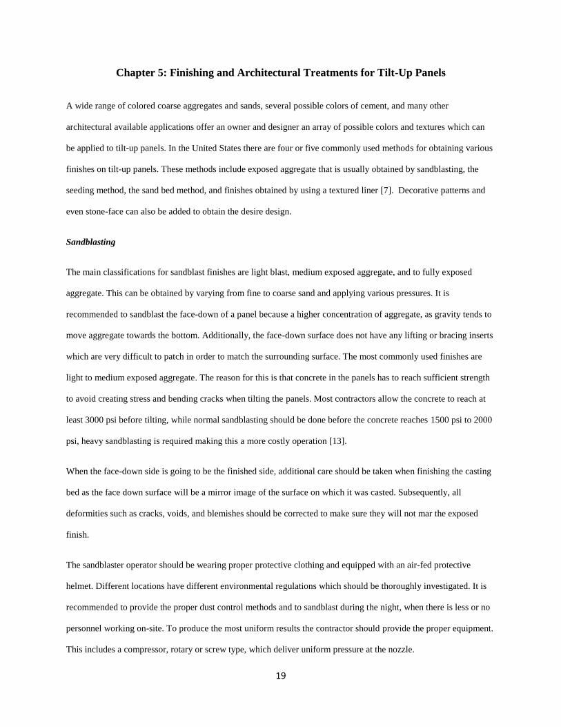
Sandblasting
The main classifications for sandblast finishes are light blast, medium exposed aggregate, and to fully exposed
aggregate. This can be obtained by varying from fine to coarse sand and applying various pressures. It is
recommended to sandblast the face-down of a panel because a higher concentration of aggregate, as gravity tends to
move aggregate towards the bottom. Additionally, the face-down surface does not have any lifting or bracing inserts
which are very difficult to patch in order to match the surrounding surface. The most commonly used finishes are
light to medium exposed aggregate. The reason for this is that concrete in the panels has to reach sufficient strength
to avoid creating stress and bending cracks when tilting the panels. Most contractors allow the concrete to reach at
least 3000 psi before tilting, while normal sandblasting should be done before the concrete reaches 1500 psi to 2000
psi, heavy sandblasting is required making this a more costly operation [13].
When the face-down side is going to be the finished side, additional care should be taken when finishing the casting
bed as the face down surface will be a mirror image of the surface on which it was casted. Subsequently, all
deformities such as cracks, voids, and blemishes should be corrected to make sure they will not mar the exposed
finish.
The sandblaster operator should be wearing proper protective clothing and equipped with an air-fed protective
helmet. Different locations have different environmental regulations which should be thoroughly investigated. It is
recommended to provide the proper dust control methods and to sandblast during the night, when there is less or no
personnel working on-site. To produce the most uniform results the contractor should provide the proper equipment.
This includes a compressor, rotary or screw type, which deliver uniform pressure at the nozzle.

20
In selecting abrasives, the flint and hydrocarbon type abrasives usually cost more than silica sand, but their
properties allows for faster cutting and therefore increasing productivity. A rule of thumb is to consider that the
particle size of the abrasive will work on a similar size particle on the concrete surface. For this reason a medium or
coarse abrasive should be selected when a lightly blasted finish is desired. On the other hand, a finer abrasive should
be selected when a deeper exposure of the aggregate is desired as the finer abrasive attacks the smaller particles in
the mortar fraction of the concrete rather than aggregate. Caution has to be taken when sandblasting concrete at an
early stage, as some of the abrasives may become imbedded in the concrete creating some discoloration. Also, large
pieces of the concrete surface can “break-off” while sandblasting at this stage [7].
Seeding Method
To create the desired exposed aggregate finish, the aggregate can be either seeded over the fresh concrete or hand
placed on a wet mortar. The method chosen typically depends on the aggregate size. To accomplish this, a structural
concrete mix can be poured in the forms and consolidated to a level of 1/8-inch to 7/16-inch below the desired finish
which allows for the volume of the selected aggregate to be seeded [7]. Once the structural concrete has been
screeded to the proper level and consolidated, the aggregate is seeded carefully by shovel or by hand to completely
cover the concrete layer.
The aggregate can be embedded into the concrete surface by using a bull float over the center areas of the panel and
a darby or a straightedge along the edges and the openings. Sometimes a rolling device, like a large pipe, can be
used to help embed the aggregate into the concrete surface. The contractor should regularly check the concrete mix
when using the seeding method. A wet mix will allow too much of the aggregate to settle deeply into the panel while
a dry mix would make it very difficult to properly imbed the aggregate. It is recommended to begin the exposure of
the aggregate as soon as the concrete surface can withstand the weight of a man leaving a slight to no indentation.
Weather conditions and admixtures should be considered by the contractor as they play a big role in the time and the
rate in which the concrete sets. For example, in the heat of the summer, if the process is started too late, it becomes
extremely difficult to get proper exposure or to finish embedding the aggregate completely as the concrete becomes
drier at a faster rate. Retarders can be successfully used under proper conditions to increase the productivity by
exposing a larger area per man.

21
The most common method for exposing the aggregate after embedment is by washing and brushing the surface. The
process usually begins by using a stiff brush to remove the concrete/mortar followed by a combination of spraying
water and brushing until a uniform exposure is obtained. Hand work might be necessary to accomplish the correct
exposure. Sometimes it is necessary to clean the surface using a mild acid solution after the panels have properly
cured. The acid helps remove any cement film that may have not been completely removed during the washing
process and also helps to highlight the color of the aggregate.
The use of proper protective clothing should be worn to prevent accidents. Additionally, refer to the specifications to
make sure that the cleaning agent being used meets all requirements. When special or decorative aggregates are
being utilized, a sealer can be applied after the panels have been cleaned to further highlight the color and, in some
cases, give the aggregate a wet and glossy appearance.
Sand Bed Method
The sand bed method is recommended when the aggregate selected for exposure is 1-inch or more in diameter. This
includes large field stone materials. The two most common methods of utilizing the sand bed method to expose
aggregate are: (1) Place the aggregate on the casting bed and sprinkle sand between the aggregates and (2) spread a
layer of fine sand over the bottom of the form and then imbed the aggregate. The (1) method is rarely used in tilt-up
construction so it is not explained with further detail.
For method (2), a layer of fine sand should be sprayed at the bottom of the form to about 1/3 the diameter of the
aggregate being used. Uniform-size aggregate is preferred as it produces a more uniform exposed surface. The
aggregate is pushed into the sand, tightly, to obtain the densest coverage possible. This is generally done by hand
and the contractor should take caution to insure that the adequate aggregate density is obtained around the edges,
corners, and openings [7].
When the aggregate is in place a fine spray of water can be used to settle the sand around the aggregate so that each
piece is held securely in place. In some cases, a thin cement slurry layer can be placed over the aggregate and
allowed to dry to insure that the aggregate is not dislodged when the normal concrete is being placed.
After the aggregate is imbedded, the reinforcement steel, lift and brace anchors, and all other items are placed in the
form. As on any exposed concrete surface, all reinforcement support that might become in contact with the surface
22
should be either plastic or galvanized steel. Another option is to hang the reinforcing steel and all other items from
the top of the form, subsequently eliminating the need for chair support and their exposure to the surface after the
panel is in place. Finally, all sand clinging to the exposed aggregate surface can be removed by brushing and
washing with a high pressure hose once the panel has been erected.
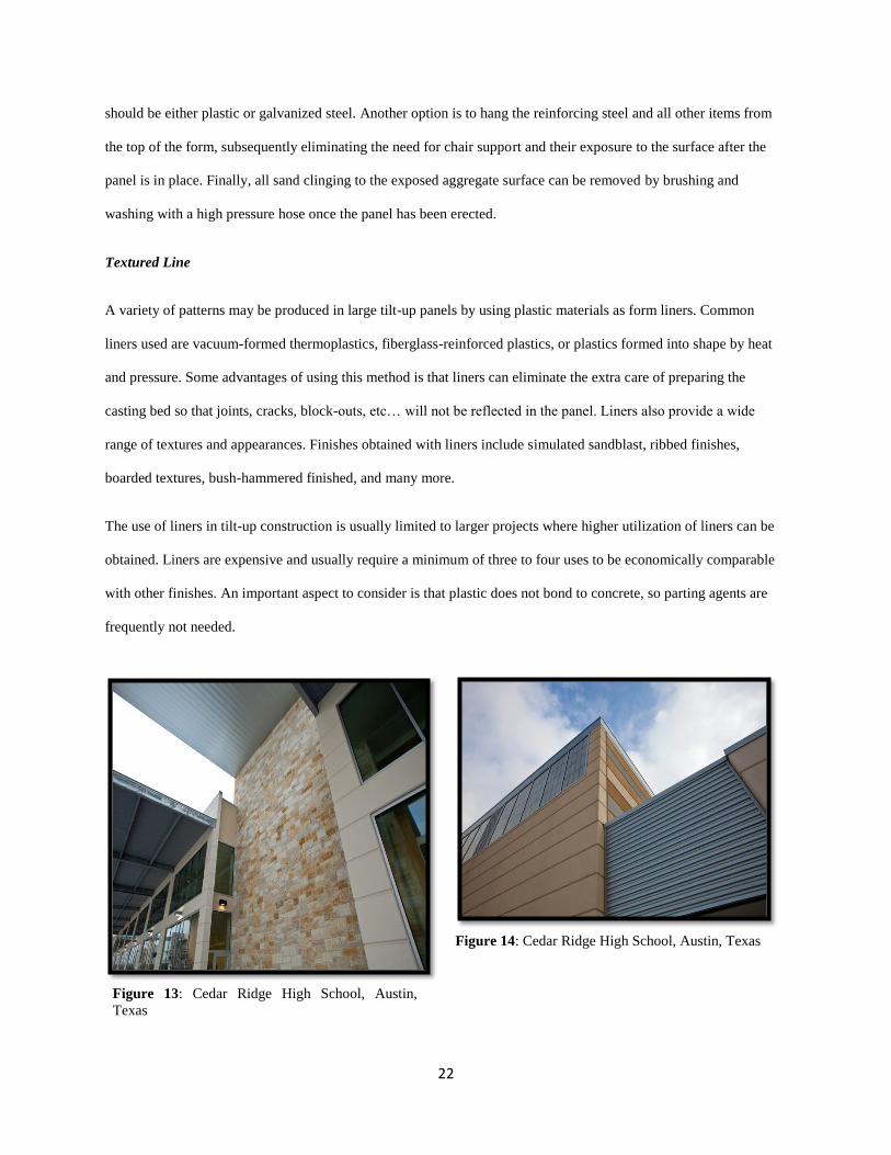
Textured Line
A variety of patterns may be produced in large tilt-up panels by using plastic materials as form liners. Common
liners used are vacuum-formed thermoplastics, fiberglass-reinforced plastics, or plastics formed into shape by heat
and pressure. Some advantages of using this method is that liners can eliminate the extra care of preparing the
casting bed so that joints, cracks, block-outs, etc… will not be reflected in the panel. Liners also provide a wide
range of textures and appearances. Finishes obtained with liners include simulated sandblast, ribbed finishes,
boarded textures, bush-hammered finished, and many more.
The use of liners in tilt-up construction is usually limited to larger projects where higher utilization of liners can be
obtained. Liners are expensive and usually require a minimum of three to four uses to be economically comparable
with other finishes. An important aspect to consider is that plastic does not bond to concrete, so parting agents are
frequently not needed.
Figure 14: Cedar Ridge High School, Austin, Texas
Figure 13: Cedar Ridge High School, Austin,
Texas

23
Figure 18: Liner at Wiley Middle School, Austin,
Texas
Figure 17: Charlie Rouse High School, Austin, Texas
Figure 16: Stone Finish at Cedar Creek High School
Figure 19: Liner at Charlie Rouse High School,
Austin, Texas
Figure 15: Cedar Creek High School, Austin, Texas

24
Figure 21: Panel Placement and Painting at
Gupton Stadium, Austin, Texas
Figure 22: Textured Concrete Finish at Gupton
Stadium, Austin, Texas
Figure 20: Gupton Stadium, Austin, Texas

25
Chapter 6: Why Tilt-Up Construction?
Building using tilt-up construction brings cost benefits that are more favorable to the owner when compared to other
building methods. Tilt-up construction will save money and building time, two powerful reasons in making the
decision of methods to use. To build with tilt-up construction benefits the owner, the designer, and the contractor or
builder.
Owner Benefits
To really see the benefits of tilt-up construction, the owner has to see the advantages of concrete buildings overall.
Concrete is a rugged, strong material that is both impact proof and abrasion resistant. This means that concrete will
not wear out even when exposed to the heavy service imposed by the industrial and commercial sector. In addition,
the solid tilt-up panels are almost impossible to penetrate offering added security to vandalism and breaking in.
Tilt-up panels can be easily designed to provide a 2 to 4 hour or more fire rating [13]. Good protection against fire
eliminates any problems with compliance with the requirements of a local building and city codes. A good fire
rating allows for maximum use of the site when locating the building with respect to property lines. It also helps to
reduce changes in fire insurance rates.
There is an array of almost unlimited aesthetic treatments available for tilt-up construction. Panel color, texture, and
pattern can be varied with the selection of plain walls, exposed aggregate walls, painted walls, sculptures walls,
textured walls, and a combination of surface finishes. All of these choices are available at any location since tilt-up
construction is done using local materials. An additional advantage of tilt-up construction is that it helps reduce the
cost of heating and air conditioning of the entire facility. Concrete mass in tilt-up panels not only slows down heat
transfer, it also stores heat during the daylight hours and releases it during the cooler night hours. Because of the
concrete greater mass, the thermal resistance requirements of tilt-up walls average about 30 percent less than the
thermal resistance of lightweight walls [13]. This translates in the need of less costly and more efficient heating and
cooling equipment. Tilt-up panels also provide for an excellent enclosure for passive solar designs, because of the
concrete’s heat storage properties. In addition, the concrete greater mass also helps reduce the outside noise coming
into the building.

26
Tilt-up buildings can go up faster than buildings constructed using more conventional methods, giving the owner the
earliest building occupancy and reducing the risk of losing profit due to delayed start-up of the facility. Tilt-up
buildings also have the possibility of expanding if required by the owner. Connections can be detailed so that it is
easy to remove, reset, and reuse panels.
Contractor Benefits
Tilt-up construction can become more attractive to the contractor or builder as this method saves on construction
time, labor, and materials. All of the concrete work is done in an accessible horizontal surface. The crews work at
ground level, increasing labor productivity in pouring, finishing, and curing the concrete. No scaffolding is required
as wall heights get higher, reducing the indirect costs of renting temporary structures or equipment and increasing
safety. At the job site, foundation work can be going on at the same time as panel fabrication.
Tilt-up is a relatively simple construction method that can be done by semiskilled and unskilled workers reducing
the overall labor costs. The materials used – concrete and reinforcing steel – are also relatively inexpensive, and the
amount of formwork (edge forms only, rather than wall faces) is at a minimum. Additionally, by casting the panels
as close to their final position as possible, erection time can be reduced as the crane will only need to handle the
panels once when setting them in the final position.
Designer Benefits
The advantages that benefit the owner and the contractor also benefits the architect/designer. Tilt-up offers freedom
when selecting the size and shape of the panels and this provides flexibility and rewards innovation in the
preliminary design stages. The designer has an almost limitless choice of architectural treatments, offering the owner
an array of colors, patterns, and textures to choose from.
In addition to aesthetic advantages, tilt-up construction also gives some advantages in structural performance.
Design tables are available that enable the designer to use tilt-up panels as bearing walls providing good support for
roof systems, elevated slabs, and floor slabs. The procedure used to analyze tilt-up panels takes into account the
influence of the variable moment of inertia on member stiffness and the effects of deflections on moments and
forces. The elimination of columns and beams to support the roof loads around the periphery of the building
contributes to reducing the costs of a tilt-up building. Tilt-up panels can also act as shear walls, providing excellent

27
resistance to lateral forces of wind and earthquakes. Tilt-up panels can also rest on any type of foundation support
such as isolated pad footings, caissons, pile caps, floating slab, continuous ribbon footing, formed and cast
foundation walls, and retaining walls.

28
Chapter 7: Summary and Conclusion
Tilt-up construction has been around for a long time, but it was not until the late 1940’s that it really started gaining
popularity with the introduction of the mobile crane. Since then, tilt-up construction has undergone many
innovations and refinements, and has now developed into a building method commonly used by many concrete
contractors and general contractors in the construction industry.
In the design of a tilt-up structure the panels should always be designed to withstand the in-place loads, live loads,
wind loads, and most importantly, lifting loads. The designer should take into account the lifting inserts layout and
all architectural features incorporated into the final design of the structure. The designer can refer to building codes
such as ACI 551 and ACI 319 for additional guidelines and requirements in the tilt-up design.
Good planning is the key part to all successful construction work, but it is especially critical in tilt-up construction if
all the cost, schedule, and safety benefits are to be realized. To insure an efficient construction procedure,
consideration must be given to the casting location of panels and erection sequence. It is important for the contractor
to develop a panel casting layout to ensure the most efficient casting and lifting of the panels. For tilt-up
construction, the concrete floor slab is usually the most convenient place for casting tilt-up panels. The floor slab
can be used as the “work table” for panel forming, casting, bracing, and erecting. If there is no accessibility to the
floor slab, temporary casting slabs can be used instead for casting tilt-up panels. It is important to understand the
main construction process for tilt-up construction, which includes: edge form, bondbreaker, reinforcement,
insulation, lifting, bracing and connecting. The lifting or erection of the panels is a critical phase during tilt-up
construction. It is imperative that the designer, contractor and usually an erection sub-contractor plan and check all
rigging and tilting procedures carefully to ensure panel erection is done safely and efficiently. The correct crane
should be selected based on the panel design. The general rule for sizing the crane state that the crane capacity
should be a minimum of two or three times that of the heaviest panel including the weight of all the rigging gear.
A wide range of colored coarse aggregates and sands, several possible colors of cement, and many other
architectural applications available offer an array of possible colors, textures, and finishes that can be applied to tilt-
up panels. The most commonly used methods to create the desired panel appearance include sandblasting, seeding
method, sand bed method, and finishes obtained by using textured liners.

29
Tilt-up construction is a simple construction method that offers benefits directly related to meeting specific costs,
schedule, and performance requirements. New and innovative architectural design techniques have given tilt-up
more versatility. Tilt-up construction also benefits the owner, the designer, and the contractor or builder. For
example, all the concrete work in tilt-up construction is done in an accessible horizontal surface, increasing labor
productivity in forming, pouring, finishing, and curing the concrete. Since no scaffolding is required, this method
reduces the indirect costs of renting temporary structures. Additionally, the materials used - concrete and reinforcing
steel – are also relatively inexpensive, and the amount of formwork (edge forms rather than wall faces) is kept at a
minimum.
In conclusion, tilt-up construction basically involves job-site prefabrication of concrete building members under
controlled and relatively economic conditions. Tilt-up construction is generally identified with industrial and
commercial building, but has been increasingly been used in other types of buildings such as parking lots,
residences, shopping centers, and churches. It is important to recognize the opportunities and advantages tilt-up
construction has to offer. Even though tilt-up is not a new idea, it has been proven to be one of the most efficient and
cost effective construction methods known to date.
30
Bibliography
[1] Bob Moore Construction Company. “Tilt-Up Construction: History and Uses.” Accessed January 21, 2012.
http://www.concretecontractor.com/tilt-up-concrete/construction-history/
[2] Building Code Requirements for Structural Concrete and Commentary (ACI 318-2008). American
Concrete Institute, 2008.
[3] Burns, Muriel. “Exposing Tilt-Up Panels – How to Add Texture, Color, and Beauty Using Chemical
Retarders,” Tilt-Up Construction: ACI Compilation (1979): 64-67.
[4] Collins, Thomas F. The Design of Tilt-Up Structures. Know How Publications in Assistance of the
Portland Cement Association, Eugene, Oregon, 1982.
[5] Composite Technologies Corporation. Questions and Answers about Non-Composite THERMOMASS
Building Insulation Systems – 9th
Edition. Boone, IA, 2008.
[6] Courtois, Peter D. “Location of Inserts – Stresses in Panels.” Tilt-Up Construction: ACI Compilation
(1979): 38-46.
[7] Martin, Jerry. “Architectural Treatments for Tilt-Up Panels,” Tilt-Up Construction: ACI Compilation
(1979): 57-63.
[8] Payne, Elmer H. Flexural Stresses in Precast Concrete Tilt Slab Panels During Erection. Proceedings of
the CSE Specialty Conference on Computers in Structural Engineering Practice, Montreal, Canada (1977):
201-237.
[9] Spears, Ralph E. Tilt-Up Construction, Design Considerations – An Overview. Presented at the Annual
University of Dayton Tilt-Up Construction Workshop, Dayton, Ohio; and a Tilt-Up and Site-Cast Concrete
Construction Conference held at Purdue University, W. Lafayette, Ind., 1929.
[10] The Quandel Group, Inc. “Tilt-up History.” Accessed January 21, 2012.
http://quandel.com/service_modules/tiltup.html.
[11] Tilt-Up Concrete Association. “Building with Tilt-Up.” Accessed March 18, 2012. http://www.tilt-
up.org/build/
[12] Tilt-Up Concrete Structures (ACI 551-R92). American Concrete Institute, 1997.

31
[13] Tilt-up Construction: A Collection of Articles from the Concrete Construction Magazine. Concrete
Construction Publications, Inc., and World of Concrete Center, Illinois, 1982
[14] Weiler, G., and N.D. Nathan. Design of Tilt-Up Concrete Wall Panels. Department of Civil Engineering,
University of British Columbia/Canadian Portland Cement Association, Vancouver, 1979
32
Vita
Jesús Alberto Schuldes was born in Monterrey, Mexico. After completing his work at Instituto Cumbres y Alpes de
Monclova, Mexico and Westlake High School in Austin, Texas, in 2006, he attended The University of Texas at
Austin where he received the degree of Bachelor of Science in Civil Engineering in December 2009. During the
following years, he was employed as an engineer by Lymon C. Reese & Associates and American Constructors, Inc.
In January, 2011, he began a Master of Science Degree in the Construction Engineering and Project Management
Program at The University of Texas at Austin.
Permanent Address: [email protected]
This report was typed by the author.