Embed Size (px)
Citation preview

Copyright
by
Chunhong Lu
2013
The Thesis Committee for Chunhong Lu
Certifies that this is the approved version of the following thesis:
Conductive Nickel Nanostrand-Reinforced Nanocomposites
APPROVED BY
SUPERVISING COMMITTEE:
Mourad Krifa
Joseph H. Koo
Supervisor:

Conductive Nickel Nanostrand-Reinforced Nanocomposites
by
Chunhong Lu, B.E.
Thesis
Presented to the Faculty of the Graduate School of
The University of Texas at Austin
in Partial Fulfillment
of the Requirements
for the Degree of
Master of Science in Textile and Apparel Technology
The University of Texas at Austin
May 2013

iv
Acknowledgements
First and foremost, I would like to thank my primary advisor, Dr. Mourad Krifa, for
his support, encouragement, and patience throughout my education and the assembly of this
report. I would also like to thank Dr. Joseph H. Koo, for his valuable advice and enthusiastic
interest in the conductive nanocomposites and Hao Wu, for his help and support throughout
my education. I truly appreciate the help and expertise provided by the faculty, staff, and
graduate students here in the School of Human Ecology, Division of Textiles and Apparel
Technology, as well as the love and unconditional support provided by my friends and
family.

v
Abstract
Conductive Nickel Nanostrand-Reinforced Nanocomposites
Chunhong Lu, M.S.T.A.T.
The University of Texas at Austin, 2013
Supervisor: Mourad Krifa
Conductive and flexible nanocomposites can have wide applications in textiles,
including wearable sensors, antenna, electrodes, etc. The objective of this research is to
develop electrically conductive fibers and films that are flexible and deformable for use
in textile structures able to accommodate the drape and movement of the human body. To
achieve this objective, we evaluate the electrical properties of PEDOT:PSS/nickel
nanostrand as well as nylon 6/nickel nanostrand nanocomposites. Nickel nanostrands
(NiNS) were first used to reinforce an intrinsically conductive polymer, Poly(3,4-
ethylenedioxythiophene) (PEDOT:PSS), in order to fabricate nanocomposite films with
high electrical conductivity. The electrical properties of the films were evaluated by the
Van der Pauw method. The addition of 10 wt% nanostrands in PDOT:PSS provided a
two order of magnitude improvement in electrical conductivity. In addition to
PDOT:PSS, nylon 6/NiNS nanocomposite fibers were produced using electrospinning
and exhibited diameters in the sub-micron range. The NiNS-reinforced fibers had
electrical conductivity that exceeded the ESD range, which offers the potential for use in
protective textile applications.

vi
Table of Contents
List of Tables ....................................................................................................... viii
List of Figures ........................................................................................................ ix
Chapter 1 Introduction .............................................................................................1
1.1 Motivation .................................................................................................1
1.2 Background: Conductive textiles ..............................................................1
1.2.1 Inherently conductive polymers ....................................................4
1.2.2 Carbon fibers .................................................................................5
1.2.3 Coated fibers .................................................................................6
1.3 Nanocomposites materials ........................................................................7
1.4 Conductive nanocomposites .....................................................................9
1.5 Nanofillers...............................................................................................11
1.5.1 Carbon nanotubes........................................................................12
1.5.2 Carbon black ...............................................................................13
1.5.3 Carbon nanofibers .......................................................................14
1.5.4 Graphite.......................................................................................15
1.5.5 Nickel nanostrands ......................................................................17
1.6 Problem statement and objectives ...........................................................19
Chapter 2 Conductive Poly (3,4 ethylenedioxythiophene):Poly(4-styrene sulfonate)
(PEDOT:PSS)/Nickel Nanostrands Nanocomposites ...................................21
2.1 Materials .................................................................................................21
2.2 Sample preparation .................................................................................22
2.3 Characterization ......................................................................................25
2.3.1 Electrical resistivity measurement ..............................................25
2.3.2 Morphology.................................................................................28

vii
2.4 Results and discussions ...........................................................................28
2.4.1 Electrical properties ....................................................................28
2.4.2 Morphology.................................................................................32
2.5 Summary .................................................................................................34
Chapter 3 Fabrication of Nylon/Ni Nanostrand Nanocomposites .........................36
3.1 Materials .................................................................................................36
3.1.1 Electrospinning technique ...........................................................36
3.2 Sample preparation .................................................................................37
3.3 Characterization ......................................................................................38
3.4 Results and discussions ...........................................................................38
3.4.1 Electrical properties ....................................................................38
3.4.2 Morphology.................................................................................38
3.5 Summary .................................................................................................41
Chapter 4 Conclusion .............................................................................................42
References ..............................................................................................................44

viii
List of Tables
Table 1 Formulation processed by Thinky planetary mixer ..................................24

ix
List of Figures
Figure 1 Conductivity range for different applications [8, 9]. .................................3
Figure 2 Energy gap for different materials [16]. ....................................................5
Figure 3 SEM images of (A) a SWNT-coated Kevlar fiber, scale bar is 20 μm, and
(B) enlargement of image in A; scale bar is 5 μm [36]. .....................6
Figure 4 Various states and configurations of particles in dry state and when dispersed
in liquids [46]. .....................................................................................8
Figure 5 TEM micrographs of pressed plates illustrating the dispersion of 1 wt%
MWNT in polycarbonate: (a) relatively big agglomerates; (b) MWNTs
show a better dispersion with more individual tubes in the matrix; (c)
Well dispersed MWNT [47]. ..............................................................9
Figure 6 The illustration of percolation in lattice [54]. ..........................................11
Figure 7 Various types of nanoscale materials [58]. ..............................................12
Figure 8 Molecular structures of a single-walled carbon nanotube (SWNT) and of a
multi-walled carbon nanotube (MWNT) [64]...................................13
Figure 9 Carbon black structure [69]. ....................................................................14
Figure 10 TEM showing the structure of a VGCNF with the cylindrical hollow core at
the center [70] and the double-layer carbon nanofibers [71]. ...........14
Figure 11 Simplifies schematic for the graphite intercalation/exfoliation process [77].
...........................................................................................................16
Figure 12 The electrical percolation threshold with the function of aspect ratios [79].
...........................................................................................................17
Figure 13 Three-dimensional structures of nickel nanostrands. ............................18

x
Figure 14 Percolative behaviors and resistivity of nickel nanostrands and carbon
nanofibers in polyimide [81]. ............................................................19
Figure 15 Molecular structure of PEDOT:PSS [90]. .............................................22
Figure 16 Diagram of Thinky mixing principle [91]. ............................................23
Figure 17 10 wt% polymer nanocomposites during curing process. .....................25
Figure 18 Electrical conductivities of common materials [92]. .............................26
Figure 19 Measurement of a square conductivity sample in the Van der Pauw
geometry [95]. ...................................................................................26
Figure 20 Electrical conductivity measurement results at mixing time 20s. .........29
Figure 21 Electrical conductivity measurements for nanocomposites with mixing time
of 3min with grinding media and 10min without grinding media. ...30
Figure 22 Electrical conductivity measurement results for all nanocomposites. ...31
Figure 23 Comparison of electrical conductivity of nanocomposites at mixing time of
3min. .................................................................................................32
Figure 24 Optical images of 5 wt% NiNS composites and 5 wt% CNT composites at
the magnification of 10×, mixing time of 20s...................................33
Figure 25 Optical image of 10 wt% NiNS nanocomposites at the magnification of
10×, mixing time of 20s. ...................................................................33
Figure 26 Optical images of 10 wt% nanostrands nanocomposites at the
magnification of 10×, mixing time of 3min with grinding media (left)
and10min without grinding media (right). ........................................34
Figure 27 Optical image of 10 wt% nanostrands nanocomposites at the magnification
of 10×, mixing time of 3min without grinding media. .....................34
Figure 28 Schematic diagram of electrospinning [103]. ........................................37
xi
Figure 29 SEM images of 5 wt% nanostrands reinforced electrospun nylon
nanocomposites at different magnifications. ....................................39
Figure 30 EDX mapping and spectrum of 5 wt% NiNS-reinforced electrospun nylon
nanocomposites. ................................................................................40
1
Chapter 1 Introduction
1.1 Motivation
The long-term goal of this research is to fabricate highly conductive fibrous structures
that are flexible, deformable, and stretchable, i.e., able to accommodate the drape and movement
of the human body. Such structures have the potential to enable significant progress in the area
of smart textiles and wearable electronics. Though significant efforts are made in making
conductive composites, most existing research focused on incorporating conductive fillers into
non-conductive polymer matrix, the resultant products do not exhibit very high electrical
conductivity that could compare to traditional materials like metals used for antennas and other
components. The metals have the shortcomings of being heavy, lack of flexibility and corrosion
in harsh environment. So it is necessary to find new materials to fabricate structures that are light
weight, flexible, durable and most important of all, of high electrical conductivity.
The specific objective of this research is to establish the feasibility of embedding novel
conductive nanofillers, i.e., nickel nanostrands, in moderately-conductive polymer matrices to
produce nanocomposite structures with high electrical conductivity that far exceeds the
electrostatic discharge (ESD) range. Combining optimal components in a nanocomposite
structure that is spinnable into fibers and threads will help us to achieve conductivity levels
heretofore unseen in common electrically conducting thermoplastic composites based on fillers,
such as carbon black or carbon nanotubes.
1.2 Background: Conductive textiles
In recent years, the function of clothing or garments has seen a rapid expansion to new
applications such as wearable electronics, and is no longer limited to the basic need of reacting to
and protecting the body from environmental changes. As a result, new technology has been

2
introduced to the textile industry to combine textiles with integrated electronic devices, such as
antennas [1], in order to meet some special needs. The development of wireless communication
systems make it of great importance to expand the application of antennas devices into body-
centric system [2]. The potential use of wearable antennas for space missions [2] was proposed
since the flexible designs make them ideal for applications where light-weight, robust systems
are crucial. The importance of developing wearable textile antenna systems to support the work
of emergency worker and firemen [3] are also stressed because of the raised awareness of the
importance of equipping firefighters, paramedics and other rescue workers with the most
advanced materials. Meanwhile, the possible application for athletes garments that help coaches
gather biomechanical and physiological information are explored [4]. Moreover, a woven
antenna which can be unobtrusively integrated into a garment and used for mobile
telecommunications was discussed [5].
Based on the above antenna design principles, Salonen et al. [6] developed a planar
inverted-F antenna (PIFA) with flexible substrate, which can be placed on the sleeves of
clothing. The operational frequency is 2.45 Hz, which was intended for the Bluetooth
application. It was the first time a flexible antenna was proposed for commercial smart clothing.
However, in this study, the flexible material used for the substrate of the antenna was not
mentioned. More recently, several researchers [7] have developed textile micro-strip antennas by
integrating metallic woven fabrics patch and ground plate with dielectric substrates. The
shortcoming of such cloth is rigidity and inflexibility. Thin metallic wires break easily in the
weaving process, therefore woven metallic cloth has been restricted to rather coarse threads of
fairly thick wires [1]. In addition, several disadvantages of metal will compromise the
performance of antennas; for instance, they will corrode very quickly in harsh environment if not
properly maintained; another issue is the poor adhesion between radiating element and the
substrate supporting it. As a result the overall lifetime of the antenna will be reduced
substantially.
3
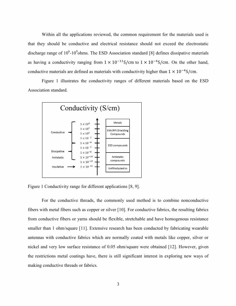
Within all the applications reviewed, the common requirement for the materials used is
that they should be conductive and electrical resistance should not exceed the electrostatic
discharge range of 106-10
9ohms. The ESD Association standard [8] defines dissipative materials
as having a conductivity ranging from to . On the other hand,
conductive materials are defined as materials with conductivity higher than .
Figure 1 illustrates the conductivity ranges of different materials based on the ESD
Association standard.
Figure 1 Conductivity range for different applications [8, 9].
For the conductive threads, the commonly used method is to combine nonconductive
fibers with metal fibers such as copper or silver [10]. For conductive fabrics, the resulting fabrics
from conductive fibers or yarns should be flexible, stretchable and have homogenous resistance
smaller than 1 ohm/square [11]. Extensive research has been conducted by fabricating wearable
antennas with conductive fabrics which are normally coated with metals like copper, silver or
nickel and very low surface resistance of 0.05 ohm/square were obtained [12]. However, given
the restrictions metal coatings have, there is still significant interest in exploring new ways of
making conductive threads or fabrics.

4
In the textile and material sciences literature, there are currently three common options to
make conductive fibers [13]: (1) produce fiber from inherently conductive materials, (2) coat
fibers with conductive polymer or metal, and (3) fill polymer fibers with conductive carbon or
metallic materials to produce conductive nanocomposites. The following paragraphs discuss
each of these approaches.
1.2.1 INHERENTLY CONDUCTIVE POLYMERS
Some organic polymers capable of conducting electricity have recently been developed.
These polymers become conductive upon partial oxidation or reduction, a process commonly
referred to as doping. The electrical properties of conductive polymers can be reversibly changed
over the full range of conductivity from insulators to metallic conductors.
The free electron model [14] is useful for explaining electrical conduction in metals. This
model assumes that the valence electrons of the metal, depicted by a gray circle (Figure 2), are
free to move throughout the volume of the metal leading to electrical conduction because there is
no forbidden gap. However, for the case of conduction in semiconductors and insulators, this
free electron model is not applicable. The valence and conduction bands of metals overlap
significantly due to the lack of energy gap. Semiconductors have band gaps less than 2.5 eV and
insulators have band gaps higher than 2.5 eV. Figure 2 shows the fundamental difference for
metals, semiconductors, and insulators. The filling of the bands and the size of the energy gap
can be used to determine which category of conductor, semiconductor, or insulator a material
belongs to. For metals, no energy gap will be found. The electrons in both conduction band and
the holes in a valence band are allowed to move throughout the material to conduct electricity.
For semiconductors, only a small number of electrons to be present in the conduction band due
to thermal energy, and they do not have good conductivity. For insulators, energy band is too
large for electrons to be promoted to the conduction band by the thermal energy; as a result,
these materials do not conduct electricity [15].

5
Figure 2 Energy gap for different materials [16].
There are several inherently conductive polymers that have been studied, such
as PEDOT:PSS [17], polyaniline (PANi) [18], and polypyrrole (PPy) [19], etc. Since late 1970s,
many researchers have been dedicated to develop the use of conductive polymers in a number of
applications [20]. In terms of electrical conductivity, it is reported that polyaniline pellets have
conductivity in the range of 5.35-7.56 S/cm depending on the processing time and pressure [21].
The electrical conductivities of undoped polypyrrole and 3-derivatized polypyrrole were 0.0266
S/cm and 0.0141 S/cm, respectively [22]. PEDOT:PSS film obtained from aqueous solutions has
conductivity around 1S/cm [23]. It is noted that the inherent conductivity of these polymers are
not very high. Methods like doping [24], incorporating other materials such as carbon nanotubes
[25] are usually used to improve the electrical conductivity.
1.2.2 CARBON FIBERS
Carbon fibers , which can be obtained from precursors like polyacrylonitrile (PAN) [26],
pitch [27], or rayon [28], have the advantage of light weight and high strength. Because of these
characteristics, carbon fibers have been used in various fields, such as weight reduced aircraft
[29], medical devices [30], automotive industry [31], etc. Compared with pitch- or rayon-based
carbon fibers, PAN-based carbon fibers show higher mechanical properties in terms of strength
and modulus. Pitch-based carbon fibers are used in applications requiring good thermal and
electrical conductivities which cannot be readily obtained from PAN-based carbon fibers [32].

6
For instance, Park et al. [33] used the electrospinning technique to prepare carbon fibers with
stabilization and carbonization and finally obtained electrical conductivity ranging from 63 to 83
S/cm, about 10 times higher than that of carbon fibers made from other bases.
1.2.3 COATED FIBERS
In order to fabricate highly conductive textile fibers for various electronic applications,
coated fibers can be obtained by coating fibers with metal, conductive polymers or carbon
materials. Jur, et al. [34] reported the conductivity of inorganic metals applied onto the surface of
non-conductive fibrous networks. According to the authors, nylon fibers coated with silver
showed high conductivity up to 1950 S/cm; cotton fibers and paper coated with ZnO had
effective conductivity of up to 24 S/cm. Ni-Cu composite was also used for the coating of aramid
fibers and the electrical resistance of conductive Ni-Cu aramid fiber was 0.035 Ω/cm [35].
Carbon materials like carbon nanotubes and graphene nano-ribbons are also reported to
be used as coating material for Kevlar fibers [36]. The SWNT-coated Kevlar fiber (Figure 3) has
uniform surface and diameter about 12µm. The filament had a conductivity of 65 S/cm, which
was higher than the conductivity graphene nano-ribbon coated Kevlar fibers of 20 S/cm or that
of MWNT coated Kevlar fibers of 9 S/cm.
Figure 3 SEM images of (A) a SWNT-coated Kevlar fiber, scale bar is 20 μm, and (B)
enlargement of image in A; scale bar is 5 μm [36].
7
Oxidative chemical vapor deposition (OCVD) technique [37] was used to coat PEDOT
onto viscose and polyester (PET) yarns. The coated PET yarns had higher conductivity of 14.2
S/cm. The conductive polymer PEDOT:PSS [38] was also successfully used for coating nylon
fibers to fabricate a flexible fabric keyboard.
1.3 Nanocomposites materials
Nanotechnology is now becoming one of the most promising areas that benefit a variety
of industries in the 21st century. Nanocomposites usually refer to the combination of a polymer
matrix with reinforcing constituents consisting of nanoscale fillers with high aspect ratios (L/d >
300), and which have at least one dimension in the range of 1–100 nm [39]. Commonly used
nanoscale fillers include carbon nanotubes [40], carbon nanofibers [41], and nano-clay particles
[42]. One advantage of nanocomposites is that with the incorporation of nanofillers into
insulating polymers, they can be turned into electrically or thermally conductive
nanocomposites. The properties of fabricated nanocomposites are not only related to the
properties of the individual components but also depend on the morphological and interfacial
properties, which are interpreted as the communication between the matrix and filler [43]. Thus,
when discussing about polymer nanocomposites, three important terms will often come up:
matrix, the reinforcement and the interfacial region.
Critical factors for the processing of nanocomposites primarily include the breaking-up of
agglomerations of nanofillers, and the good dispersion of nanofillers in the polymer system [44,
45]. There is a difference between agglomeration and aggregation. As shown in Figure 4, in dry
powder state, nanoparticles agglomerate because of the Van der Waals forces and of the large
surface to volume ratio; on the other hand, the particles aggregate due to strong chemical bonds
caused by sintering [46]. It is possible to control the state of nanoparticles during the synthesis
process [46]. Usually, when agglomerated nanoparticles are put into a liquid, they can still be

8
separated by overcoming the weaker attractive forces with certain methods, whereas it is not the
case for the aggregated nanoparticles.
Figure 4 Various states and configurations of particles in dry state and when dispersed in liquids
[46].
During the processing of nanocomposites, the agglomeration should be overcome,
otherwise, more nanofillers are need in the polymer system to obtain the desired property, at the
cost of other properties [47]. With the breaking up of agglomerates, a good dispersion of
nanoparticles can be achieved in the polymer system. Figure 5 shows an example with (a)
agglomerates of multi-wall carbon nanotubes (MWNT), (b) agglomerates that were broken
down, and better-dispersed MWNT, and (c) good dispersion of MWNT throughout the polymer
system [47]. Thus, separation of agglomerates and good dispersion of individual nanofillers are
very important to obtain a homogenous system.

9
Figure 5 TEM micrographs of pressed plates illustrating the dispersion of 1 wt% MWNT in
polycarbonate: (a) relatively big agglomerates; (b) MWNTs show a better dispersion
with more individual tubes in the matrix; (c) Well dispersed MWNT [47].
1.4 Conductive nanocomposites
Conductive nanocomposites have drawn extensive attention because of wide applicability
in electronic industry like electromagnetic shielding [20], sensors [48], etc. To fabricate
conductive nanocomposites, the basic ideas are either incorporating nanofillers into intrinsically
conductive polymers, or imparting conductive nanofillers into non-conductive polymers.
Intrinsically conductive polymers were discussed above. In this section, the incorporation of
conductive fillers into non-conductive polymers is focused.

10
Most polymers are natural electrical insulators. The basic idea for imparting electrical
conductivity to such polymers is to add some conductive fillers like carbon nanotubes, carbon
black, carbon fibers, or graphite, into the polymer system. In other words, the composites consist
of highly conductive additives incorporated into polymer compounds, meaning that they are
extrinsically enhanced to be conductive.
For a given type of polymer, the conductivity of the composites depends on the type,
shape and content of conductive fillers. Conductivity in composites is due to formation of a
continuous network of filler particles throughout the polymer matrix [49].
The main advantage of carbon-based nanofillers is that they have low weight and high
aspect ratio, which improves desired properties of the polymer nanocomposites system with a
very small loading of fillers [50]. The major requirement is that the fillers are homogenously
dispersed in the polymer system, which can be achieved using different techniques such as melt
processing [51], high shear mixing [52], three roll milling mixing [53], etc. It is not uncommon
to see reports about low loading of nanofillers efficiently improving the electrical conductivity of
non-conductive polymer-based nanocomposites, which can be referred as low percolation
threshold.
To better understand the electrical properties of nanocomposites related to percolation
threshold, we can refer to classic percolation theory which can explain this phenomenon [54].
According to the theory (Figure 6), let p be the probability that a square lattice is occupied and
electrical current can only go through the near occupied sites, which are conductors. Percolation
threshold means a critical concentration (pc), at which electrical current is able to go through the
lattice from one end to the other. When the concentration is larger than this critical value, the
material can be considered as a conductor, and an insulator if concentration is low than pc.

11
Figure 6 The illustration of percolation in lattice [54].
This theory is usually used for composites made of conductive fillers and insulating
polymers when the insulator to conductor transition needs to be described. Here is the scaling
law [55] that is commonly used regarding to the critical concentration of conductive fillers pc.
(1)
Where p is the concentration of conductive filler and σ is the experimental conductivity
value, B is the proportionality constant, pc is the electrical percolation threshold and t is the
critical exponent depending on the dimensionality of the conductive network which varies for
different materials. Typically, for two dimension networks, t=1.3 whereas for three dimension
networks, t=2.0. It is possible to determine the percolation threshold and obtain the
dimensionality by fitting the classic percolation scaling law to the experimental data [56].
1.5 Nanofillers
Nanoscale fillers can be in different shapes and sizes (Figure 7). According to the
literature [57], the nanoscale fillers can be classified into three different groups. The first is the
three-dimensional nanofillers which are referred to as relatively equi-axed particles (<100 nm in
their largest dimension), for instance, silica. The second is layered materials which have only one
dimension in nanometers, typically thickness of 1nm, and the aspect ratio of the other
dimensions is at least 25. A good example is nanoclay or layered silicates [58]. The third type is

12
nanotube or nanofiber fillers, which are elongated structures with two dimensions in nanometers
leading to large aspect ratios of at least 100 [59].
Figure 7 Various types of nanoscale materials [58].
The nanofillers can also be categorized as organic and inorganic according to the
chemical composition. An excellent review by Gangopadhyay and De [60] discussed the various
applications of inorganic nanoparticles, such as SiO2, SnO2, TiO2, Fe2O3, in reinforced
intrinsically conducting polymer nanocomposites. However, more research has focused on
carbon-based nanofillers reinforced polymer nanocomposites. So the carbon-based nanofillers
are discussed in this section.
1.5.1 CARBON NANOTUBES
Since the discovery of carbon nanotubes (CNTs) [61], considerable studies have focused
on the area of CNTs reinforced polymer nanocomposites. Normally carbon nanotubes are
divided into two groups depending on the number of graphite walls they have: (1) multiwall
carbon nanotubes (MWNTs) with several walls (Figure 8, right), or a ‘Russian doll’ structure in
which concentric tubes are bonded to another by weak Van de Waal forces [62]; and (2) single
wall carbon nanotubes (SWNTs) (Figure 8, left). The intrinsic conductivity of CNTs is one of the
properties that make them popular in the application of CNTs-polymer composites. For example,
MWNTs have very high conductivity (~18000 S/cm) along tube axis [63]. As reported [40], a
13
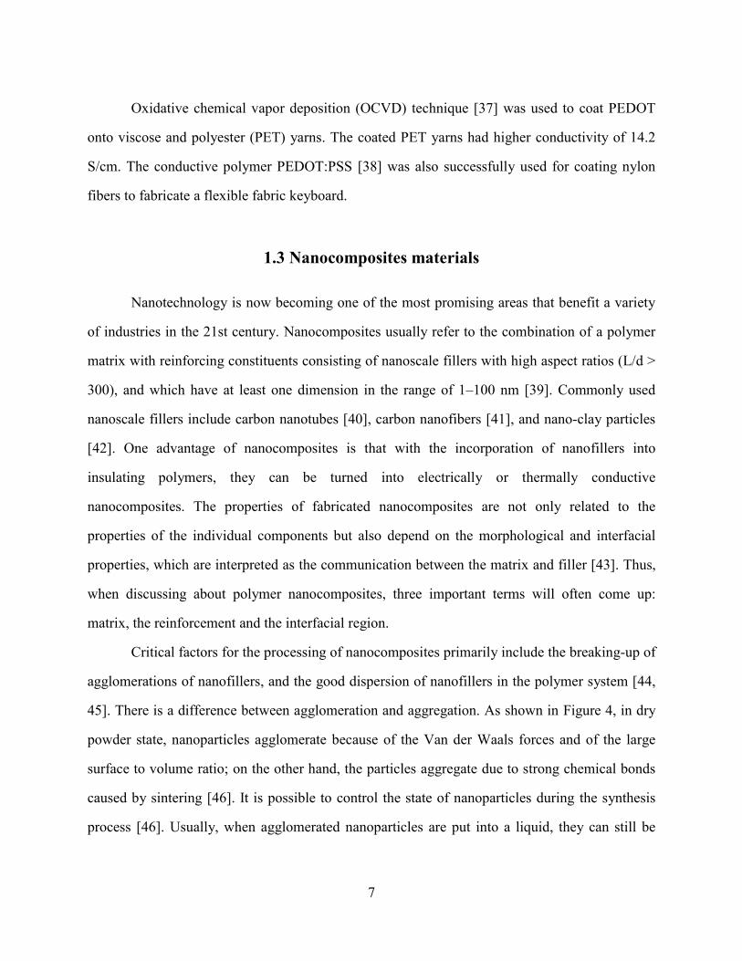
very small loading of SWNTs (about 0.04wt%) was able to improve the electrical conductivity
of 6 magnitudes from 10-14
to 10-8
S/cm.
Figure 8 Molecular structures of a single-walled carbon nanotube (SWNT) and of a multi-walled
carbon nanotube (MWNT) [64].
1.5.2 CARBON BLACK
Carbon black particles (Figure 9) have been incorporated into polymers for the purpose
of improving electrical conductivity, mechanical properties, color and UV stability. So, carbon
black is widely used as conductive filler in non-conductive polymer systems because it is easy to
fabricate and its cost is relatively low [65]. Carbon black also have high surface area and
aggregate behavior, which can lead to the relatively higher loadings in order to achieve desired
conductivities [66]. As filler, carbon black with nanoscale particles in branched structure can
have better adhesion with polymer chains [67]. However, compared with nanotubes, carbon
black has lower aspect ratio and another problem is sloughing, which is the shedding of carbon
particles [68], but the price is much lower than CNTs, for about $1000/ton.

14
Figure 9 Carbon black structure [69].
1.5.3 CARBON NANOFIBERS
Carbon nanofibers have a hollow-core structure that can either be single layer [70] or
double layer [71] of graphite plate stacked parallel or at certain angle from the fiber axis (Figure
10). Carbon nanofibers have diameters of about 100 nm and several microns in length, which
gives high aspect ratio (>100) [72]. Carbon nanofibers have larger size than MWNTs, which
makes them easy for researchers to handle. The intrinsic electrical properties of CNFs are
excellent, since some studies reported that carbonated and graphitized CNFs have electrical
resistivity as low as 4×10⁻³
ohm-cm [41] and 5×10⁻⁵
ohm-cm [70]. As a result, carbon fibers have
been widely studied as reinforcement for polymer nanocomposites.
Figure 10 TEM showing the structure of a VGCNF with the cylindrical hollow core at the center
[70] and the double-layer carbon nanofibers [71].

15
1.5.4 GRAPHITE
Among different carbon-based fillers, natural graphite has very high electrical
conductivity of 104
S/cm [73], which leads to the wide use of this material. However, one of the
biggest problems with the large quantity application of this material to increase electrical
properties is the poor balance with mechanical properties. To solve this problem, the nanoscale
fillers are introduced.
Graphite has a layered structure with one-atom-thick sheets of carbon. Within the layer,
carbon atoms are attracted to each other covalently in the form of hexagonal shape and different
layers are bonded together by weak Van der Waal forces [74]. Expandable graphite (EG), which
has high aspect ratio and excellent electrical conductivity, consists of delaminated graphite
sheets which connect with each other and form a network with pores of various sizes from 10 nm
to 10 μm. EG is expandable up to hundreds of times its initial volume at high temperature, as a
result, the graphene sheets will separate at the nanoscopic level along the c-axis of the graphene
layers [75].
Graphite nanoplatelets can be obtained by separating graphite layers through intercalation
and exfoliation. Figure 11 is the schematic showing the intercalation and exfoliation process. The
first stage involves heating graphite powder with potassium metal to form an intercalation
compound. Followed by the addition of aqueous solvent for the exfoliation process, the graphite
nanoplatelets can be formed. It is reported that exfoliated graphite nanoplatelets (xGnP™), are
very cost effective and can improve many properties [76]. It is expected that nanocomposites
prepared with xGnP in polymer systems will present excellent electrical conductivity.

16
Figure 11 Simplifies schematic for the graphite intercalation/exfoliation process [77].
Despite the fact that more loading of carbon-based nanofillers will lead to higher
conductivity of nanocomposites, it may result in the aggregation of carbon-based fillers as well,
which will lose balance with the mechanical properties of the nanocomposites. For instance,
some researchers [78] investigated the effect of treatment on the electrical properties of
CNTs/epoxy nanocomposites, and concluded that SWNTs required a higher concentration than
MWNTs to attain percolation threshold. The authors also tested the treatment or
functionalization of the nanofillers which did improve the mechanical properties of
nanocomposites because of better interconnection between fillers and matrix [79], but decreased
the electrical conductivity since the treatment reduced the aspect ratio (Figure 12).

17
Figure 12 The electrical percolation threshold with the function of aspect ratios [79].
1.5.5 NICKEL NANOSTRANDS
Other than the widely used carbon-based fillers, nickel nanostrands (NiNS)
(manufactured by Conductive Composites) represent a relatively new type of highly conductive
fillers produced by chemical vapor deposition (CVD) coating and have not been studied to a
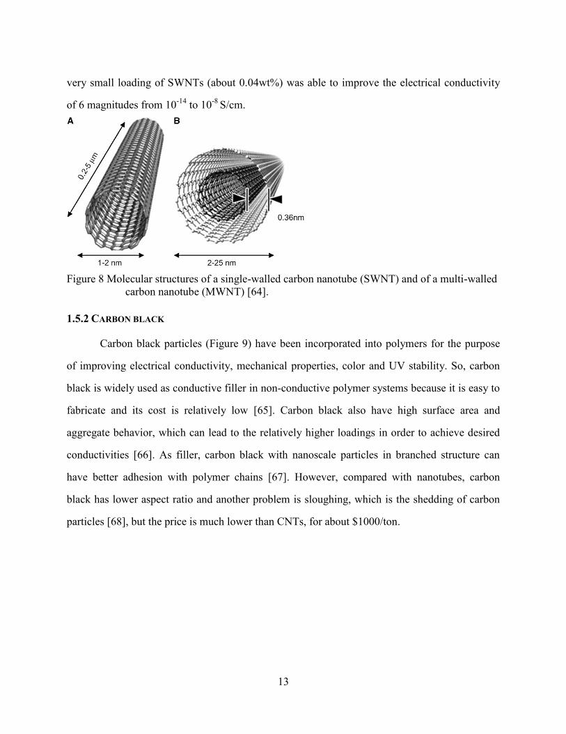
large extent. Nanostrands are branched 3D structures (Figure 13) consisting of submicron
diameter nickel particles linked in chains, micrometers to millimeters in length [80]. According
to their developer (Conductive Composites), nickel nanostrands have a considerable advantage
over CNTs and other metallic fillers due to their branched structure which allows more
interconnects within the polymer matrix allowing for significantly higher conductivity [80-83]. It
is also commonly known that nickel is a metal with high conductivity and nontoxic, and the raw
material cost of nickel nanostrands (about $5/gram) which is competitive compared to some
carbon-based nanofillers, particularly SWNT [84]. Specifically, while nickel nanostrands are
comparable to SWNTs in high aspect ratio, the driving factor of using new material in industry is
the substantial price difference between the two materials.
18
Figure 13 Three-dimensional structures of nickel nanostrands.
So far, substantial work has been done in terms of the conductivity and of dispersion of
CNTs [40] or carbon nanofibers [41] in polymer systems. On the other hand, very little work
about the dispersion of nickel nanostrands (NiNS) has been demonstrated [85, 86]. In this
research, the effects of the NiNS on the electrical properties of polymer nanocomposites were
studied. It will fill the gap and facilitate a better understanding of the 3D geometry of nickel
nanostrands.
Compared with carbon nanofiber-reinforced nanocomposites, the advantage of nickel
nanostrands in terms of electrical conductivity is evident according to results published by
Conductive Composites (Figure 14). For both nanofillers, the higher volume fraction of
nanomaterials will lead to the significant decrease of electrical resistivity. However, as
mentioned before, the addition of carbon-based filler should be limited to a certain range, such as
0.2 vol% listed in this figure, since the high loading may lead to the aggregation of fillers that
will decrease the mechanical properties of nanocomposites. And with the same volume fraction,
the nanostrands appear to perform better than carbon-based nanofibers in the improvement of
electrical conductivity for about four orders at 0.05 vol% [81].

19
Figure 14 Percolative behaviors and resistivity of nickel nanostrands and carbon nanofibers in
polyimide [81].
1.6 Problem statement and objectives
The purpose of this research is to establish the feasibility of embedding novel conductive
nanofillers, i.e., nickel nanostrands, in moderately-conductive polymer matrices (PEDOT:PSS)
to create nanocomposites structures with high electrical conductivity that exceeds the
electrostatic discharge (ESD) range.
Based on our literature survey, very little research has been conducted on imparting
electrical conductivity to fibers or other flexible structures through the incorporation of Ni
nanostrands. The objective of this research is to develop conductive structures that are flexible
and deformable for use in textile structures able to accommodate the drape and movement of the
human body. To achieve this objective, we combine two major approaches discussed above: (a)
an inherently conductive polymer as matrix and (b) Ni nanostrands as fillers were used. Thus, we
evaluate the electrical properties of PEDOT:PSS/nickel nanostrands nanocomposites. A range of
composite formulations was fabricated. The electrical properties of the films were evaluated by
the Van der Pauw method. Film surface morphology and dispersion of nanoparticles are assessed

20
by scanning electron microscopy and optical microscopy. The data collected will help to
optimize different compositions for electrical properties.
As a second objective, we attempted to impart conductivity to a different polymer system
based on nylon. The main goal here is to use the electrospinning technique to fabricate nylon
nanofibers reinforced by nickel nanostrands. With this method, we will be able to determine
whether the nickel nanostrands can efficiently improve the electrical conductivity of different
polymers.

21
Chapter 2 Conductive Poly (3,4 ethylenedioxythiophene):Poly(4-styrene
sulfonate) (PEDOT:PSS)/Nickel Nanostrands Nanocomposites
2.1 Materials
In this study, a colloidal dispersion of poly (3, 4 ethylenedioxythiophene): poly (4-styrene
sulfonate) (PEDOT:PSS) is chosen as polymer system because of its higher conductivity
amongst intrinsically conductive polymers as well as its ease of processing. Though poly (3, 4
ethylenedioxythiophene) (PEDOT) was insoluble in water, the use of a polyelectrolyte, poly
(styrene sulfonic acid) (PSS), helped solve the insolubility problem. In water, this complex
system yields a stable, deep blue microdispersion [87]. In addition, PSS also performs the role of
charge-balancing dopant to provide better electrical conductivity [88]. Since it is possible to
realize the ‘solubility’ with use of PSS, increasing studies have been focused on poly(3,4
ethylenedioxythiophene):poly(4-styrene sulfonate) (PEDOT:PSS) [17]. PEDOT:PSS (Figure 15)
colloidal dispersion in water can be easily made into films on different substrates by simple
methods such as solution casting and spin coating. It is widely used as conductive polymer [88].
The conductivity of PEDOT:PSS is about 1S/cm, which is low for applications such as
electrodes of flexible electronics. Secondary dopants or additives, such as alcohols or high
boiling point solvents, are sometimes added to the dispersion in order to improve the electrical
conductivity of PEDOT:PSS films [89].

22
Figure 15 Molecular structure of PEDOT:PSS [90].
For this research, the polymer suspension PEDOT:PSS was purchased from Sigma-
Aldrich Chemical Co. and was used as received. The PEDOT:PSS colloidal dispersion in water
has a solid weight percentage of 1.3 wt%. The nickel nanostrands were provided by Conductive
Composites Co. Bayer Material Sciences’ Baytubes C150P MWNTs were used. Mixing and
dispersion of nickel nanostrands in polymer system was conducted according to the
manufacturer’s guidelines.
2.2 Sample preparation
The desired weight fraction of nickel nanostrands were added into water, and screened
through a stainless steel mesh sheet with pore size of 0.0065’’ according to ASTM E2016-06, in
order to reduce aggregates and homogenize the nanostrands. Once dried out, the screened
nanostrands were added into the water-based polymer system for initial “manual” mixing. It is
claimed by the manufacturer that other mixing method, such as ultra-sonication will damage the
three-dimensional structure of nanostrands. So a Thinky planetary centrifugal mixer (ARV-310)
was used to disperse the nickel nanostrands in the polymer system.

23
The Thinky mixer is a planetary mixer (Figure 16) that can disperse and degas materials
at various time and speed. The liquid PEDOT:PSS was put in to the cup with volume no less
than 50% that of the cup and then the solid nanostrands were added. In our experiment, in
consideration of the arising temperature, the vacuum was not used for degassing. In principle,
during mixing, the container with materials will revolve and rotate in planetary way. With the
centrifugal force, the materials go toward the inner wall of cups and then go down along the wall
in a spiral fashion under other forces and then to the center of the cup and finally go up [91].
With the continuous movement of materials in the cups, the two phase materials can be
homogenously mixed.
Figure 16 Diagram of Thinky mixing principle [91].
Table 1 shows the wt% compositions of the formulations we tested. A mixing duration of
20s with a speed of 2000rpm was first used for all samples. The selection of a less aggressive
mixing duration as an initial setup was made in order to minimize the probability of destroying
the three-dimensional structure of the nanostrands and achieve the best electrical conductivity. In
order to test the impact of dispersion on conductivity, samples were also prepared at the same
mixing speed but with a mixing time of 3min and with grinding media for all formulations. The
purpose of the grinding media was to further reduce agglomerates and improve dispersion of the
fillers within the polymer system. Indeed, the grinding media consist of a number of small
zirconium dioxide balls (3mm in diameter). During the centrifugal mixing process, these small
balls collide with each other, making the nanoparticles clumps separate under the force of
friction. In consideration of the heat generated with the usage of grinding media, the mixing time
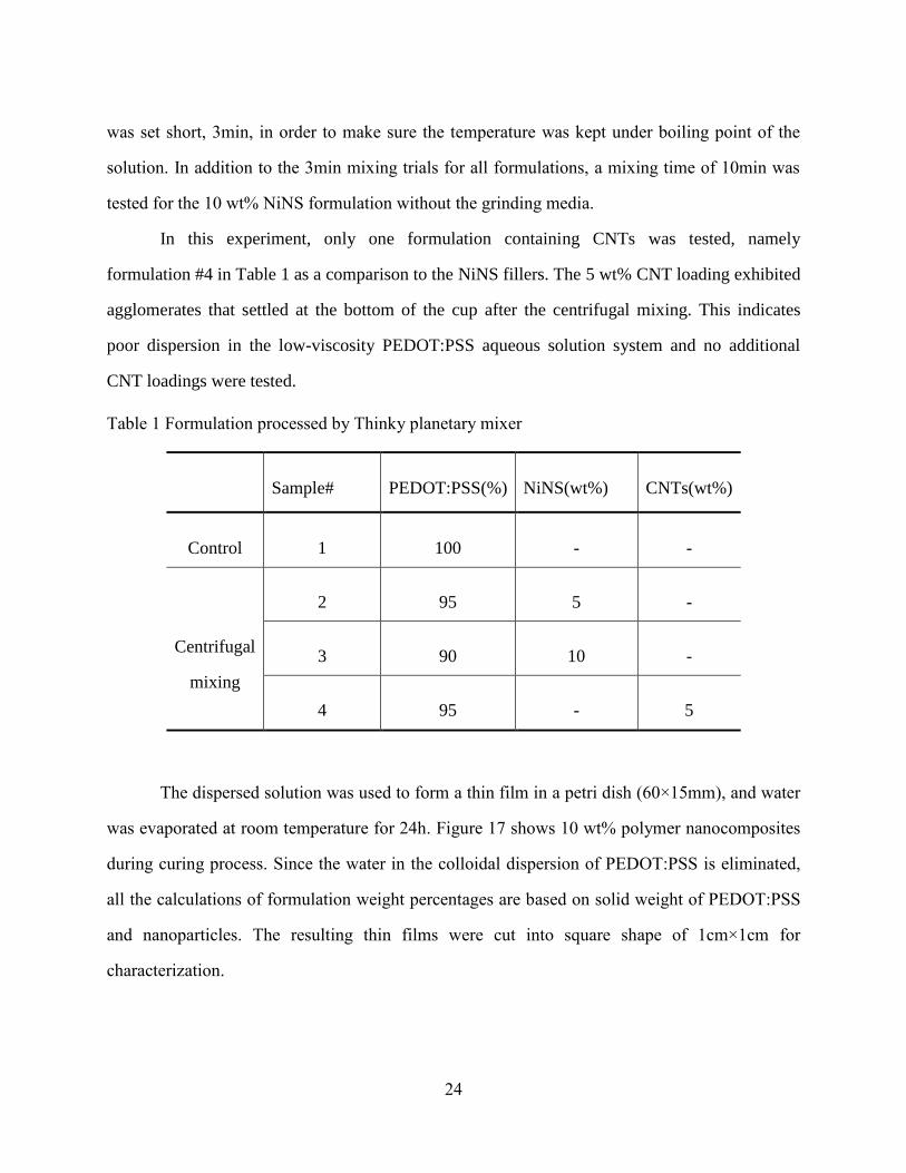
24
was set short, 3min, in order to make sure the temperature was kept under boiling point of the
solution. In addition to the 3min mixing trials for all formulations, a mixing time of 10min was
tested for the 10 wt% NiNS formulation without the grinding media.
In this experiment, only one formulation containing CNTs was tested, namely
formulation #4 in Table 1 as a comparison to the NiNS fillers. The 5 wt% CNT loading exhibited
agglomerates that settled at the bottom of the cup after the centrifugal mixing. This indicates
poor dispersion in the low-viscosity PEDOT:PSS aqueous solution system and no additional
CNT loadings were tested.
Table 1 Formulation processed by Thinky planetary mixer
Sample# PEDOT:PSS(%) NiNS(wt%) CNTs(wt%)
Control 1 100 - -
Centrifugal
mixing
2 95 5 -
3 90 10 -
4 95 - 5
The dispersed solution was used to form a thin film in a petri dish (60×15mm), and water
was evaporated at room temperature for 24h. Figure 17 shows 10 wt% polymer nanocomposites
during curing process. Since the water in the colloidal dispersion of PEDOT:PSS is eliminated,
all the calculations of formulation weight percentages are based on solid weight of PEDOT:PSS
and nanoparticles. The resulting thin films were cut into square shape of 1cm×1cm for
characterization.

25
Figure 17 10 wt% polymer nanocomposites during curing process.
2.3 Characterization
2.3.1 ELECTRICAL RESISTIVITY MEASUREMENT
The most commonly used technique to characterize the electrical property for composites
is the four-point probe or Van der Pauw method since it has the advantage of eliminating
contact-resistance effect [40]. This method is also known as the resistivity/Hall effect measuring
system and is widely used for the resistance measurement of thin materials. According to the
commonly used classification of the electrical conducting materials (Figure 18), the materials
with electrical resistivity lower than 10-6
S/cm are treated as insulators, with electrical resistivity
between 10-6
S/cm and 102 S/cm as semiconductors, and those with greater than 10
2 S/cm as
metals. The electrical conductivity is the reciprocal of electrical resistivity.
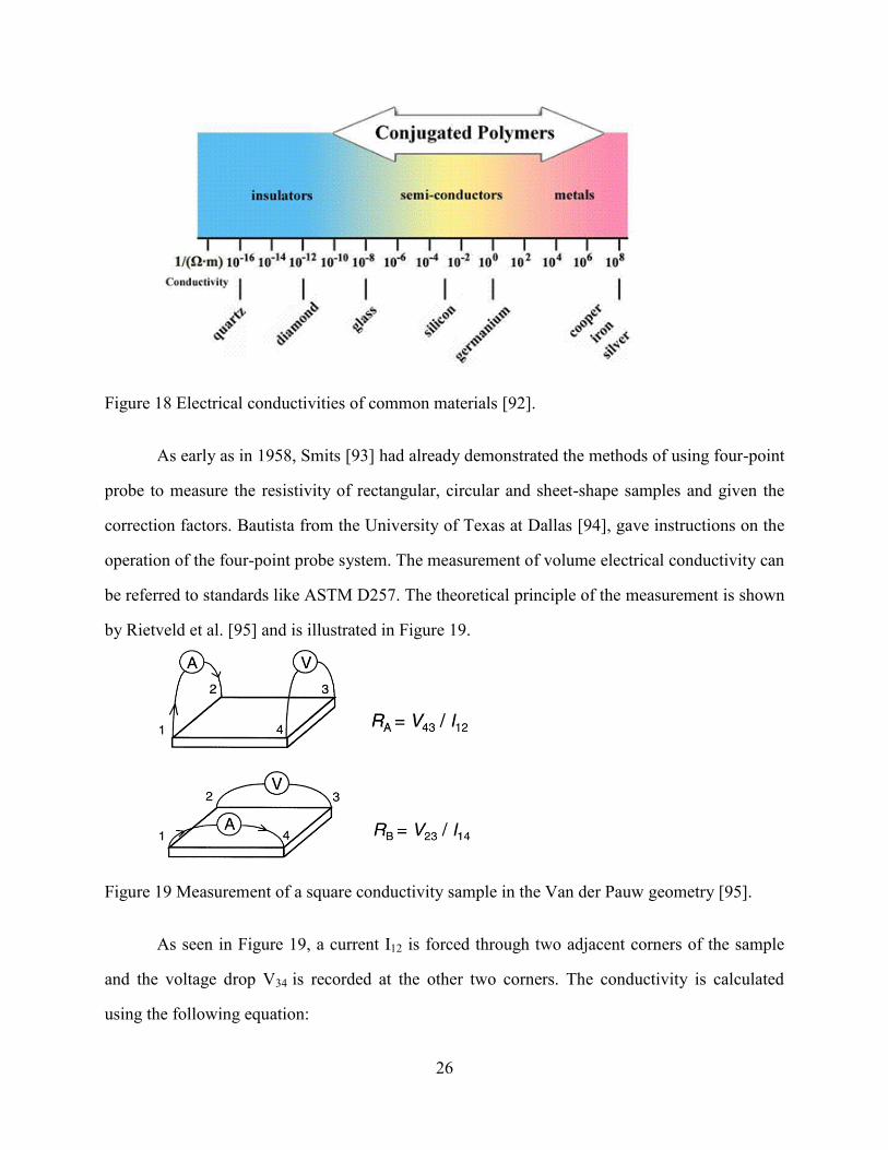
26
Figure 18 Electrical conductivities of common materials [92].
As early as in 1958, Smits [93] had already demonstrated the methods of using four-point
probe to measure the resistivity of rectangular, circular and sheet-shape samples and given the
correction factors. Bautista from the University of Texas at Dallas [94], gave instructions on the
operation of the four-point probe system. The measurement of volume electrical conductivity can
be referred to standards like ASTM D257. The theoretical principle of the measurement is shown
by Rietveld et al. [95] and is illustrated in Figure 19.
Figure 19 Measurement of a square conductivity sample in the Van der Pauw geometry [95].
As seen in Figure 19, a current I12 is forced through two adjacent corners of the sample
and the voltage drop V34 is recorded at the other two corners. The conductivity is calculated
using the following equation:

27
(
) (
) (2)
Where RS is sheet resistance (ohm); RA= (V34/I12+V12/I34)/2 (Ω); and RB=
(V41/I23+V23/I41)/2 (Ω)
(3)
(4)
Where ρ is the resistivity (ohm-cm); t is the sample thickness (m); and σ is the
conductivity (S/m).
Besides the four-point method, the two-point method is also frequently used to measure
the electrical properties of polymer nanocomposites. For instance, Zhang [96] used a Keithley
6487 (Keithley Instruments Inc. Ohio, USA) to test the direct current electrical resistivity and
avoid contact resistance by applying silver to both ends of the tapes and it turned out that the
contact resistance was far smaller than sample resistance and could be neglected. The resistivity
is calculated in the following equation (5)
(5)
where R is the resistance, w, t and l are width, thickness and length of the samples,
respectively.
Another way to obtain electrical properties is introduced by Zhou [97]. Using an Agilent
4294-A precision impedance analyzer, the impedance of the CNT/epoxy composites samples at
every frequency was measured to further calculate the resistivity combined with the sample
geometry. As for the geometry, the author used a diamond saw to cut the composites into
rectangular bar with the dimension of 8mm×4mm×1mm (length, width and thickness). During

28
the measurement, the two end surfaces were fully coated with gold. To determine the resistivity
of CNT/epoxy samples, the reader can refer to Zhou et al. [97].
√ (6)
Where R is resistance, C is the capacitor’s capacitance and f is frequency
(7)
(8)
Where ε is the permittivity of the dielectric and ρ is the resistivity. They are material
parameters. L, W and T are length, width and thickness, respectively.
√ (9)
Equation (9) can be obtained by substituting (7) and (8) into (6), where is the
resistivity of the composites calculated [97].
In this research, the Van der Pauw method was used for the characterization of electrical
sheet resistance of materials. The tests were conducted according to Van der Pauw method with a
Keithley 4200 model and Agilent station. The current source sweeps from negative to positive
value. The voltage difference can be obtained from the difference of two voltmeters and from the
slope of the resulting voltage-current linear curve, RA or RB can be obtained.
2.3.2 MORPHOLOGY
Scanning electron microscopy (SEM, Quanta 650) and optical microscopy were used to
observe the morphology of films.
2.4 Results and discussions
2.4.1 ELECTRICAL PROPERTIES
Figure 20 shows the volume electrical conductivity of the pristine PEDOT:PSS films, as
well as the formulations prepared with a 20s mixing time. Pristine PEDOT:PSS films have an
average electrical conductivity of about 2.8S/cm. The addition of 5 wt% carbon nanotubes or 5

29
wt% nickel nanostrands appears to slightly decrease the electrical conductivity. With the addition
of 10 wt% NiNS, the electrical conductivity increased to about 5S/cm.
Figure 20 Electrical conductivity measurement results at mixing time 20s.
Therefore, the results obtained with the formulations above do not appear satisfactory in
terms of the improvement of the electrical conductivity. There are some possible reasons: first, a
less than optimal dispersion of the nanofillers in the polymer system could be one important
reason for this result. Second, the viscosity of the colloidal suspension is as low as 7.27cp, which
means that after mixing, the polymer system is not viscous enough to hold the nanoparticles
throughout the system, and sediments could accumulate at the bottom of the petri dish during
curing. This will lead to uneven distribution of nanoparticles in the matrix and uneven film
surface. Third, PEDOT:PSS is already a doped system which consists of two components. The
mechanism of charge transport in PEDOT:PSS is not completely understood, though it is stated
that the two-phase system can be interpreted as PSS-saturated PEDOT diluted in PSS [87]. The
addition of a third component at low 5 wt% may have disturbed the formation of the conductive
pathway.

30
The longer mixing time of 3min at speed of 2000rpm with the grinding media, as well as
for 10min without grinding media are expected to result in a better dispersion of the nanofillers.
Figure 21 shows the results obtained for those trials. Again, the 5 wt% CNT and 5 wt% NiNS
nanocomposites did not show improved electrical conductivity. On the other hand, the 10 wt%
NiNS nanocomposites demonstrated a significant improvement with an electrical conductivity of
about 165 S/cm. It is also seen that the 10 wt% NiNS nanocomposites with 10min mixing time
has a similar electrical conductivity to that of 10 wt% NiNS with 3min mixing time and grinding
media.
Figure 21 Electrical conductivity measurements for nanocomposites with mixing time of 3min
with grinding media and 10min without grinding media.
From Figure 22, it is noted that with same speed, the mixing time plays an important role
in the dispersion of nickel nanostrands in the polymer system. The 20s mixing time is not long
enough for the nanoparticles to separate from each other and evenly disperse in the polymer.
Both the 5 wt% CNT and 5 wt% NiNS have decreased electrical conductivity because the lack of

31
connected network of nanofillers. The higher weight percentage of 10 was unsuccessful either,
with very little improvement mainly for the mentioned reason.
When the mixing time was increased to 3min and grinding media were added, it became
possible to stretch the nanostrands and disperse them evenly within the polymer. However, for 5
wt% CNT and 5 wt% NiNS, the conductivity did not increase. The possible reason is that the 5
wt% loading is not enough to form a network in a polymer system with very low viscosity. For
10 wt% loading, the nanostands were able to form good connected network because there are
enough nanostrands and good dispersion.
Similarly, the mixing time of 3min was applied, but without grinding media. It turned out
that 5 wt% CNT and 5 wt% NiNS did not have improved electrical property for the same reason
mentioned above. For the 10 wt% NiNS, the electrical conductivity was improved obviously, but
the value was about half of the electrical conductivity of 10 wt% NiNS with grinding media.
Figure 22 Electrical conductivity measurement results for all nanocomposites.

32
Figure 23 clearly shows the effects of the grinding media on the electrical conductivity.
For 5 wt%, there was no significant difference because of the insufficient nanostrands to form
conductive network. For 10 wt%, the nanocomposites mixed by grinding media has the electrical
conductivity of about 160 S/cm, which is more than twice of the 10 wt% mixed without grinding
media, at 58 S/cm. This indicates that the grinding media plays an important role in separating
the nickel nanostrands and providing good dispersion in the polymer system.
Figure 23 Comparison of electrical conductivity of nanocomposites at mixing time of 3min.
2.4.2 MORPHOLOGY
SEM images confirmed that the branched network structure of Ni nanostrands was
maintained after mixing and dispersion within the PEDOT:PSS matrix (see Figure 13). In
addition, optical microscopic images of the different nanocomposites films reveal the dispersion
of NiNS and CNTs in the polymer system was not homogenous for the 5 wt% loading and using
20s mixing time. For the CNT nanocomposites, the black dots were distributed unevenly in the
polymer system, and NiNS were not easily observed but small clumps can be seen in 5 wt%
NiNS (Figure 24).

33
Figure 24 Optical images of 5 wt% NiNS composites and 5 wt% CNT composites at the
magnification of 10×, mixing time of 20s.
The optical images (Figure 25) of 10 wt% NiNS composite did not show NiNS on the
surface, it appears there may be interconnected nanostrands structures formed underneath the
surface.
Figure 25 Optical image of 10 wt% NiNS nanocomposites at the magnification of 10×, mixing
time of 20s.
For 10 wt% NiNS nanocomposites with 3min mixing time and grinding media (Figure
26, left), and 10 wt% NiNS nanocomposites with 10min mixing time (Figure 26, right), the
optical images shows that NiNS were connected to each other, forming a good network. So the
good dispersion of NiNS in the polymer system contributes to the improvement of electrical
conductivity. Though the conductivity of 10 wt% NiNS mixed without grinding media for 3min
had lower conductivity than the same formulation of nanocomposites mixed with grinding media

34
for 3min, the optical image still shows the interconnected nanostrands in both polymer systems
(Figure 27).
Figure 26 Optical images of 10 wt% nanostrands nanocomposites at the magnification of 10×,
mixing time of 3min with grinding media (left) and10min without grinding media
(right).
Figure 27 Optical image of 10 wt% nanostrands nanocomposites at the magnification of 10×,
mixing time of 3min without grinding media.
2.5 Summary
In summary, the PEDOT:PSS/nickel nanostrands nanocomposites were processed and
fabricated by centrifugal mixing method. The electrical properties of the nanocomposites were
studied and the addition of nanostrands into the intrinsically conductive polymer system with

35
shorter mixing time did not improve the electrical conductivity, since there was no conductive
network of nanofillers formed. With longer mixing time, better dispersion of the nanostrands was
achieved which provided two orders of magnitude improvement in electrical conductivity with
10 wt% nanostrands loading.
Additional processing parameters (mixing speed) of the centrifugal mixing method will
be explored to obtain the optimal conditions for the processing of the nanocomposites. More
formulations will be performed to study their electrical property.

36
Chapter 3 Fabrication of Nylon/Ni Nanostrand Nanocomposites
As previously mentioned, a second objective we pursued is to impart conductivity to a
different polymer system based on nylon. Nylon is commonly used in clothing and is a major
component of military uniforms [98]. It is therefore a material of interest in terms of electrical
conductivity and anti-static properties. The main goal here is to use the electrospinning technique
to fabricate nylon nanofibers reinforced by nanostrands. With this method, we will be able to
determine whether the nanostrands will efficiently improve the electrical conductivity of
different polymers.
3.1 Materials
Low/medium viscosity Nylon 6 (Aegis® H8202NLB) was provided by Honeywell Co.
Formic acid (>88%) was purchased from Sigma-Aldrich Chemical Co. The nickel nanostrands
were provided by Conductive Composites Co.
3.1.1 ELECTROSPINNING TECHNIQUE
The electrospinning technique, patented by [99], is a straightforward and inexpensive
way to produce continous nanofibers with diameters covering a wide range from the microns
(2µm) to nanometers (100nm) [100]. The resulting micro or nanofibers have some typical
characteristics like large surface area to volume ratio, high porosity that can be used in a variety
of applictaions, for instance, protective clothing [101], filters [102], etc.
During the electrospinning process (Figure 28), the high voltage is applied to a polymer
solution being injected in the electric field using a syringe at a constant rate. When the solution
exits from the tip of syringe, it is shaped and influenced by surface tension, viscosity and both
electrostatic and gravitational fields [103]. A force created by mutual charge repulsion causes the
solution drop to elongate and finally leads to the formation of a conical shape known as the

37
Taylor cone [104]. Nanofibers are initiated by further elongation of the Taylor cone then
collected on the grounded collector to form a nonwoven thin film.
Figure 28 Schematic diagram of electrospinning [103].
The polymers used for this process can be either synthetic or natural polymers. In this
case, we use nylon 6 as the electrospun polymer because of its good spinnablility when dissolved
in formic acid and it can be used as garment materials in the textile industry.
3.2 Sample preparation
The desired weight fraction of nanostrands were added into water, and screened by
stainless steel mesh sheet with pore size of 0.0065’’ according to ASTM E2016-06, in order to
get reduced aggregates and homogenize the nanostrands. The nylon pellets were dissolved in
formic acid at 25% using magnetic stirrer to mix for 24h. Then the dried-out nanostrands were
added into the solution, the Thinky planetary centrifugal mixer (ARV-310) was used to disperse
the nickel nanostrands in the polymer system. The mixing time was 3min at 2000rpm. The solid
weight percentage of 5% of nanostrands was used.

38
After mixing, the homogenous grey solution was loaded in a 12ml syringe for
electrospinning. Electrospinning of both neat nylon and compounded solution was conducted
with high voltage at 25±2kV, collecting distance of 10 cm, and feeding rate at 2±1μl/min. The
electrospinning time was controlled at 5min to collect films on paper. Then the films are
carefully scraped and peeled off for characterization.
3.3 Characterization
The electrical properties of 5 wt% nanostrands/nylon nanocomposites were measured
according to the van der Pauw method mentioned earlier. Three samples were prepared for the
measurement and calculation of sheet resistance. The morphology of 5 wt% nanostrands/nylon
nanocomposites were observed by Scanning electron microscope (SEM) using a Hitachi S5500
equiped with Energy-dispersive X-ray spectroscopy (EDX).
3.4 Results and discussions
3.4.1 ELECTRICAL PROPERTIES
By calculating the electrical conductivity of the electrospun nylon/nickel nanostrand
fibers, we obtain 0.6 S/cm, for a 5 wt% nanostrand loading. Normally, pure nylon is an insulator,
which has a conductivity of lower than 10-12
S/cm. With the addition of only 5 wt% of
nanostrands, conductivity of the nanocomposites was increased more than 11 orders to a value
that exceeds the ESD range (roughly, 10-8
-10-2
S/cm), and that is within the EMI shielding range
(see
Figure 1).
3.4.2 MORPHOLOGY
The morphology of 5 wt% NiNS-reinforced electrospun nylon fibers were observed by
SEM, as shown in Figure 29. The diameter of electrospun fibers is about 500nm. The nickel

39
nanostrands appear embedded inside the nylon fibers, which explains the improved electrical
conductivity of the resultant nonwoven webs. It is also noted that the structure of the nanostrands
appears to have preserved some branching as seen in Figure 29(c)(d). However, the branching
was not observed inside a uiform fiber but inside a bead formed during the spinning process
Figure 29(d).
(a) (b)
(c) (d)
Figure 29 SEM images of 5 wt% nanostrands reinforced electrospun nylon nanocomposites at
different magnifications.
By examining the EDX spectroscopy results (Figure 30), we can further confirm that the
structures observed inside the electrospun nylon fibers are indeed nickel nanostrands. The red
dots in Figure 30(b) indicate the intensity of nickel element. The nickel nanostrands in the
nanofibers show high intensity. Red dots with lower intensity are also observed in other places

40
surrounding the fiber in focus, indicating the presence of nickel in the deeper layers of
nanofibers. The peaks of nickel in Figure 30(c) were detected from one spot of the intense red
dotted nanofibers, which further confirmed the existence of nickel nanostrands in the nanofibers.
(a) (b)
(c)
Figure 30 EDX mapping and spectrum of 5 wt% NiNS-reinforced electrospun nylon
nanocomposites.
41
3.5 Summary
Nickel nanostrands reinforced nylon nanocomposite was successfully fabricated with the
electrospinning technique by homogenously disperse nickel nanostrands in the nylon/ formic
acid solution with planetary centrifugal mixer. The nanocomposites showed significant
improvement in electrical conductivity by an order of 10. SEM images and EDX mapping of the
nanocomposites indicated the embedding of nickel nanostrands inside the structure of the
continuous nanofibers formed with a diameter about 500nm, which explains the improvement of
electrical properties of the nanocomposite.

42
Chapter 4 Conclusion
The long-term goal of this research is to fabricate highly conductive fibrous structures
that are flexible, deformable, and stretchable, i.e., able to accommodate the drape and movement
of the human body. The specific objective of this thesis research is to establish the feasibility of
embedding novel conductive nanofillers, i.e., nickel nanostrands, in moderately-conductive
polymer matrices to produce nanocomposites structures with high electrical conductivity that
exceeds the electrostatic discharge (ESD) range.
To achieve this objective, nickel nanostrands and carbon nanotubes were dispersed in
PEDOT:PSS polymer system to create nanocomposites for the study of electrical properties. The
control, 5 wt% and 10 wt% NiNS- and 5 wt% CNT-reinforced PEDOT:PSS nanocomposite
films were fabricated through cast deposition. In order to test the impact of filler dispersion with
the polymer matrix, the planar centrifugal mixing method was applied with varying mixing times
and with or without grinding media added for selected formulations. This method appeared to be
effective in bringing down the agglomeration of nanostrands in the colloid polymer system. With
the combination of grinding media and centrifugal mixing at time of 3min and speed of
2000rpm, the 10 wt% NiNS reinforced nanocomposites achieved electrical conductivity as high
as 168 S/cm, about two orders magnitude improvement in comparison with the control sample.
The 10 wt% NiNS reinforced nanocomposites mixed at speed of 2000rpm for 10min without
grinding media also showed high electrical conductivity of 164 S/cm.
SEM images confirmed that the branched network structure of Ni nanostrands was
maintained after mixing and dispersion within the polymer matrix. In addition, optical
microscopic images confirmed the electrical properties results, showing a good interconnection
of nanostrands throughout the matrix system related to the superior electrical conductivity.
Nanostrand-reinforced nylon fibers were fabricated using electrospinning. The resulting
sub-micron fibers, about 500 nm in diameter, have an electrical conductivity of 0.6 S/cm, which
43
is greatly improved compared to the insulting polymers whose conductivity is normally below
10-12
S/cm. Examination of the fiber morphology using SEM and EDX further confirmed the
successful embedding of NiNS inside the nanofiber core. This result shows the potential for
using nanostrands to produce electrically conductive nylon fibers usable in protective textiles
(anti-static, electromagnetic shielding).
In summary, this research is a first attempt to explore the dispersion of nanostrands in
intrinsically conductive as well as in insulating polymers to fabricate conductive and flexible
structure usable in textiles. In the future, additional research should be conducted on exploring
fiber processing methods such as electrospinning, other properties like mechanical and thermal
properties in order to gain a better understanding of the potential of these nanofiller in textile
applications. Finally, the nanocomposites should be incorporated into fabrics or garments to
expand the applications in textile industry.

44
References
1. Shaw, R.K., et al., The Characterization of Conductive Textile Materials Intended for
Radio Frequency Applications. Antennas and Propagation Magazine, IEEE, 2007. 49(3):
p. 28-40.
2. Kennedy, T.F., et al. Potential Space Applications for Body-Centric Wireless and E-
textile Antennas. in Antennas and Propagation for Body-Centric Wireless
Communications, IET Seminar 2007.
3. C. Hertleer, L.V.L., H. Rogier, L. Vallozzi, A Textile Antenna For Fire Fighter
Garments, in Autex. 2007.
4. Galehdar, A. and D.V. Thiel. Flexible, light-weight antenna at 2.4GHz for athlete
clothing. in Antennas and Propagation Society International Symposium, 2007 IEEE.
2007.
5. Kandhavadiuv, P., C. V., T. Ramachandran, Application of Woven Antenna in Wireless
Communication Device Integrated Apparel and Bedlinen. International Journal of
Engineering Science and Technology, 2010. 2(10): p. 5970-5976.
6. Salonen, P., et al. Effect of textile materials on wearable antenna performance: a case
study of GPS antennas. in Antennas and Propagation Society International Symposium,
2004. IEEE. 2004.
7. Kohls, E.C., et al. A multi-band body-worn antenna vest. in Antennas and Propagation
Society International Symposium, 2004. IEEE. 2004.
8. Electrostatic Discharge Association, ESD Association Advisory for Electrostatic
Discharge Terminology- Glossary. 2009, Electrostatic Discharge Association: 7900
Turin Road, Bldg. 3 Rome, NY 134409.
9. Hyperion Catalysis International. Electrical Resistivity in semi-crystalline polymers.
2002 [cited 2012 08-24]; Available from: www.hyperioncatalysis.com.
10. Yuehui, O. and W.J. Chappell, High Frequency Properties of Electro-Textiles for
Wearable Antenna Applications. Antennas and Propagation, IEEE Transactions on, 2008.
56(2): p. 381-389.
11. Locher, I., et al., Design and Characterization of Purely Textile Patch Antennas.
Advanced Packaging, IEEE Transactions on, 2006. 29(4): p. 777-788.
12. Hertleer, C., et al., The Use of Textile Materials to Design Wearable Microstrip Patch
Antennas. Textile Research Journal, 2008. 78(8): p. 651-658.
13. Skotheim, T.A., R.L. Elsenbaumer, and J.R. Reynolds, Handbook of Conducting
Polymers. 1998: Marcel Dekker Incorporated.
14. Strom, E.T. and K. Wilson Angela, eds. Pioneers of Quantum Chemistry. ACS
Symposium Series. Vol. 1122. 2013, American Chemical Society.
15. Tissue, B.M. Solid-State Band Theory. 2000; Available from:
http://www.files.chem.vt.edu/chem-ed/quantum/bands.html.

45
16. Joint-quantum. Floquet Topological Insulators. 2011; Available from:
http://jqi.umd.edu/news/floquet-topological-insulators.
17. Jang, J., M. Chang, and H. Yoon, Chemical Sensors Based on Highly Conductive
Poly(3,4-ethylenedioxythiophene) Nanorods. Advanced Materials, 2005. 17(13): p. 1616-
1620.
18. Kang, E.T., K.G. Neoh, and K.L. Tan, Polyaniline: A polymer with many interesting
intrinsic redox states. Progress in Polymer Science, 1998. 23(2): p. 277-324.
19. Ramanavičius, A., A. Ramanavičienė, and A. Malinauskas, Electrochemical sensors
based on conducting polymer—polypyrrole. Electrochimica Acta, 2006. 51(27): p. 6025-
6037.
20. Mahmoud, A., Advances in inherently conducting polymers. Makromolekulare Chemie.
Macromolecular Symposia, 1989. 24(1): p. 1-20.
21. Zhang, D., On the conductivity measurement of polyaniline pellets. Polymer Testing,
2007. 26(1): p. 9-13.
22. N. Puanglek, A.S., W. Lerdwijitjarud, Enhancement of Electrical Conductivity of
Polypyrrole and Its Derivativ. Science Journal, UBU, 2010. 1(1): p. 35-42.
23. Xia, Y. and J. Ouyang, PEDOT:PSS films with significantly enhanced conductivities
induced by preferential solvation with cosolvents and their application in polymer
photovoltaic cells. Journal of Materials Chemistry, 2011. 21(13): p. 4927-4936.
24. McCullough, R.D., et al., Self-orienting head-to-tail poly(3-alkylthiophenes): new
insights on structure-property relationships in conducting polymers. Journal of the
American Chemical Society, 1993. 115(11): p. 4910-4911.
25. Yun, D.-J., et al., Multiwall Carbon Nanotube and Poly(3,4-ethylenedioxythiophene):
Polystyrene Sulfonate (PEDOT:PSS) Composite Films for Transistor and Inverter
Devices. ACS Applied Materials & Interfaces, 2011. 3(1): p. 43-49.
26. Jain, M. and A.S. Abhiraman, Conversion of acrylonitrile-based precursor fibres to
carbon fibres. Journal of Materials Science, 1987. 22(1): p. 278-300.
27. Yang, K., et al., Preparations of carbon fibers from precursor pitches synthesized with
coal tar or petroleum residue oil. Fibers and Polymers, 2000. 1(2): p. 97-102.
28. Wu, Q.-L. and D. Pan, Scanning tunnel microscopy study of rayon-based carbon-fiber
surfaces. Journal of Applied Polymer Science, 2003. 90(3): p. 754-758.
29. Soutis, C., Fibre reinforced composites in aircraft construction. Progress in Aerospace
Sciences, 2005. 41(2): p. 143-151.
30. Van der Woude, L.H.V., S. De Groot, and T.W.J. Janssen, Manual wheelchairs:
Research and innovation in rehabilitation, sports, daily life and health. Medical
Engineering & Physics, 2006. 28(9): p. 905-915.
31. Fuchs, E.R.H., et al., Strategic materials selection in the automobile body: Economic
opportunities for polymer composite design. Composites Science and Technology, 2008.
68(9): p. 1989-2002.
32. Morgan, P., Carbon Fibers and Their Composites. 2005.

46
33. Park, S.H., C. Kim, and K.S. Yang, Preparation of carbonized fiber web from
electrospinning of isotropic pitch. Synthetic Metals, 2004. 143(2): p. 175-179.
34. Jur, J.S., et al., Electronic Textiles: Atomic Layer Deposition of Conductive Coatings on
Cotton, Paper, and Synthetic Fibers: Conductivity Analysis and Functional Chemical
Sensing Using “All-Fiber” Capacitors (Adv. Funct. Mater. 11/2011). Advanced
Functional Materials, 2011. 21(11): p. 1948-1948.
35. Liang, J., et al., Conductive aramid fiber with Ni-Cu composite coating prepared using
the metalation swelling method. Fibers and Polymers, 2013. 14(3): p. 453-458.
36. Xiang, C., et al., Carbon Nanotube and Graphene Nanoribbon-Coated Conductive
Kevlar Fibers. ACS Applied Materials & Interfaces, 2011. 4(1): p. 131-136.
37. Bashir, T., M. Skrifvars, and N.-K. Persson, Synthesis of high performance, conductive
PEDOT-coated polyester yarns by OCVD technique. Polymers for Advanced
Technologies, 2012. 23(3): p. 611-617.
38. Takamatsu, S., et al. Flexible fabric keyboard with conductive polymer-coated fibers. in
Sensors, 2011 IEEE. 2011.
39. Jordan, J., et al., Experimental trends in polymer nanocomposites—a review. Materials
Science and Engineering: A, 2005. 393(1–2): p. 1-11.
40. Bryning, M.B., et al., Very Low Conductivity Threshold in Bulk Isotropic Single-Walled
Carbon Nanotube–Epoxy Composites. Advanced Materials, 2005. 17(9): p. 1186-1191.
41. Morales-Asencio, J.M., et al., Effectiveness of a nurse-led case management home care
model in Primary Health Care. A quasi-experimental, controlled, multi-centre study.
BMC Health Serv Res, 2008. 8: p. 193.
42. Wu, H., et al., Fabrication and Characterization of Flame Retardant Polyamide 6
Nanocomposites via Electrospinning, in SAMPE TECH 2011. 2011: Fort Worth, TX.
43. Wagner, H.D. and R.A. Vaia, Nanocomposites: issues at the interface. Materials Today,
2004. 7(11): p. 38-42.
44. Lee, C.S., J.S. Lee, and S.T. Oh, Dispersion control of Fe2O3 nanoparticles using a
mixed type of mechanical and ultrasonic milling. Materials Letters, 2003. 57(18): p.
2643-2646.
45. Liu, W., et al., Preparation and characterization of PET/silica nanocomposites. Journal
of Applied Polymer Science, 2004. 91(2): p. 1229-1232.
46. Jiang, J., G. Oberdörster, and P. Biswas, Characterization of size, surface charge, and
agglomeration state of nanoparticle dispersions for toxicological studies. Journal of
Nanoparticle Research, 2009. 11(1): p. 77-89.
47. Pegel, S., et al., Dispersion, agglomeration, and network formation of multiwalled carbon
nanotubes in polycarbonate melts. Polymer, 2008. 49(4): p. 974-984.
48. Li, C. and G. Shi, Polythiophene-Based Optical Sensors for Small Molecules. ACS
Applied Materials & Interfaces, 2013.

47
49. Clingerman, M.L., et al., Development of an additive equation for predicting the
electrical conductivity of carbon-filled composites. Journal of Applied Polymer Science,
2003. 88(9): p. 2280-2299.
50. Yu, M.-F., et al., Tensile Loading of Ropes of Single Wall Carbon Nanotubes and their
Mechanical Properties. Physical Review Letters, 2000. 84(24): p. 5552-5555.
51. Cipriano, B.H., et al., Conductivity enhancement of carbon nanotube and nanofiber-
based polymer nanocomposites by melt annealing. Polymer, 2008. 49(22): p. 4846-4851.
52. Battisti, A., A.A. Skordos, and I.K. Partridge, Percolation threshold of carbon nanotubes
filled unsaturated polyesters. Composites Science and Technology, 2010. 70(4): p. 633-
637.
53. Thostenson, E.T., S. Ziaee, and T.-W. Chou, Processing and electrical properties of
carbon nanotube/vinyl ester nanocomposites. Composites Science and Technology, 2009.
69(6): p. 801-804.
54. Bunde, A. and J.W. Kantelhardt, Diffusion and Conduction in Percolation Systems, P.
Heitjans and J. Kärger, Editors. 2005, Springer Berlin Heidelberg. p. 895-914.
55. Stauffer, D., Introduction To Percolation Theory. 2 ed. 2003: Taylor and Francis.
56. Deng, H., et al., A Novel Concept for Highly Oriented Carbon Nanotube Composite
Tapes or Fibres with High Strength and Electrical Conductivity. Macromolecular
Materials and Engineering, 2009. 294(11): p. 749-755.
57. Alexandre, M. and P. Dubois, Polymer-layered silicate nanocomposites: preparation,
properties and uses of a new class of materials. Materials Science and Engineering: R:
Reports, 2000. 28(1–2): p. 1-63.
58. Kumar, A.P., et al., Nanoscale particles for polymer degradation and stabilization—
Trends and future perspectives. Progress in Polymer Science, 2009. 34(6): p. 479-515.
59. Sevil, B.Z., Küçükyavuz, Synthesis and Characterization of Polypyrrole Nanoparticles
and Their Nanocomposites with Poly(propylene). Macromolecular Symposia 2010.
295(1): p. 59.
60. Gangopadhyay, R. and A. De, Conducting Polymer Nanocomposites: A Brief Overview.
Chemistry of Materials, 2000. 12(3): p. 608-622.
61. Iijima, S., Helical Microtubules of Graphitic Carbon. Nature, 1991. 354(6348): p. 56-58.
62. Kearns, J.C. and R.L. Shambaugh, Polypropylene fibers reinforced with carbon
nanotubes. Journal of Applied Polymer Science, 2002. 86(8): p. 2079-2084.
63. Koerner, H., et al., Deformation-morphology correlations in electrically conductive
carbon nanotube thermoplastic polyurethane nanocomposites. Polymer, 2005. 46(12): p.
4405-4420.
64. Reilly, R.M., Carbon Nanotubes: Potential Benefits and Risks of Nanotechnology in
Nuclear Medicine. Journal of Nuclear Medicine, 2007. 48(7): p. 1039-1042.
65. Wu, T.M. and J.C. Cheng, Morphology and electrical properties of carbon-black-filled
poly(epsilon-caprolactone)/poly(vinyl butyral) nanocomposites. Journal of Applied
Polymer Science, 2003. 88(4): p. 1022-1031.

48
66. Ali Farshidfar, V.H.A., Hossein Nazokdast, Electrical and Mechanical Properties Of
Conducive Carbon Black/ Polyolefin Composites Mixed With Carbon Fiber, in
COMPOSITES 2006 Convention and Trade Show American Composites Manufacturers
Association. 2006: St. Louis, MO USA.
67. Knite, M., et al., Electric and elastic properties of conductive polymeric nanocomposites
on macro- and nanoscales. Materials Science & Engineering C-Biomimetic and
Supramolecular Systems, 2002. 19(1-2): p. 15-19.
68. Albert Escusa, L.W., Intrinsically Static-Dissipative Reel. 2004.
69. Sonic-Horns. Primasonic's future is black- carbon black! 2008; Available from:
http://blog.sonic-horns.com/2008/12/primasonics-future-is-black-carbon.html.
70. Tibbetts, G.G., et al., A review of the fabrication and properties of vapor-grown carbon
nanofiber/polymer composites. Composites Science and Technology, 2007. 67(7–8): p.
1709-1718.
71. Uchida, T., et al., Morphology and modulus of vapor grown carbon nano fibers. Journal
of Materials Science, 2006. 41(18): p. 5851-5856.
72. Ardanuy, M., M.A. Rodríguez-Perez, and I. Algaba, Electrical conductivity and
mechanical properties of vapor-grown carbon nanofibers/trifunctional epoxy composites
prepared by direct mixing. Composites Part B: Engineering, 2011. 42(4): p. 675-681.
73. Chen, G.-H., et al., Preparation of polystyrene–graphite conducting nanocomposites via
intercalation polymerization. Polymer International, 2001. 50(9): p. 980-985.
74. Fukushima, H., et al., Thermal conductivity of exfoliated graphite nanocomposites.
Journal of Thermal Analysis and Calorimetry, 2006. 85(1): p. 235-238.
75. Cho, D., et al., Dynamic Mechanical and Thermal Properties of Phenylethynyl-
Terminated Polyimide Composites Reinforced With Expanded Graphite Nanoplatelets.
Macromolecular Materials and Engineering, 2005. 290(3): p. 179-187.
76. Fukushima, H., Graphite nanoreinforcements in polymer nanocomposites, in Chemical
Engineering & Materials Science. 2003, Michigan State University: East Lansing.
77. Mack, J.J., et al., Graphite Nanoplatelet Reinforcement of Electrospun Polyacrylonitrile
Nanofibers. Advanced Materials, 2005. 17(1): p. 77-80.
78. Gojny, F.H., et al., Evaluation and identification of electrical and thermal conduction
mechanisms in carbon nanotube/epoxy composites. Polymer, 2006. 47(6): p. 2036-2045.
79. Gojny, F.H., et al., Carbon nanotube-reinforced epoxy-composites: enhanced stiffness
and fracture toughness at low nanotube content. Composites Science and Technology,
2004. 64(15): p. 2363-2371.
80. Conductive Composites. Nanostrands. 2011 [cited 2012 9/3]; Available from:
http://www.conductivecomposites.com/nanostrands.html.
81. Hansen, N. and G. Hansen, From Inception to Insertion: Successful Products and
Applications using Nickel Nanostrands, in SAMPE International Symposium. 2011,
Society for the Advancement of Material and Process Engineering: Long Beach, CA

49
82. Hansen, N., et al., Investigation of Electrically Conductive Structural Adhesives using
Nickel Nanostrands. Journal of Adhesion Science and Technology, 2011. 25(19): p.
2659-2670.
83. Hansen, N., D.O. Adams, and D.T. Fullwood, Quantitative methods for correlating
dispersion and electrical conductivity in conductor–polymer nanostrand composites.
Composites Part A: Applied Science and Manufacturing, 2012. 43(11): p. 1939-1946.
84. Oller, A.R., et al., Inhalation carcinogenicity study with nickel metal powder in Wistar
rats. Toxicology and Applied Pharmacology, 2008. 233(2): p. 262-275.
85. Whitworth, D.A., Processing a Nickel Nanostrand and Nickel Coated Carbon Fiber
Filled Conductive Polyethylene by Injection Molding. 2010, Brigham Young University.
86. Whalen, C.A., Dispersion and Characterization of nickel nanostrands in thermoset and
thermoplastic polymers. 2012, Texas A&M University.
87. Stöcker, T., A. Köhler, and R. Moos, Why does the electrical conductivity in PEDOT:PSS
decrease with PSS content? A study combining thermoelectric measurements with
impedance spectroscopy. Journal of Polymer Science Part B: Polymer Physics, 2012.
50(14): p. 976-983.
88. Groenendaal, L., et al., Poly(3,4-ethylenedioxythiophene) and Its Derivatives: Past,
Present, and Future. Advanced Materials, 2000. 12(7): p. 481-494.
89. Crispin, X., et al., The Origin of the High Conductivity of Poly(3,4-
ethylenedioxythiophene)−Poly(styrenesulfonate) (PEDOT−PSS) Plastic Electrodes.
Chemistry of Materials, 2006. 18(18): p. 4354-4360.
90. Ladhe, R.D., et al., p-PEDOT:PSS as a heterojunction partner with n-ZnO for detection
of LPG at room temperature. Journal of Alloys and Compounds, 2012. 515(0): p. 80-85.
91. Adhere. Thinky, Mixing and Degassing machines, conditiong planatary mixer. 2012.
92. Marianna Korzhov, R.S.a.D.A., Dreaming in Plastic, in Physics World. 2008.
93. Smits, F.M., Measurement of Sheet Resisitivities with the Four-Point Probe. The Bell
System Technical Journal, 1958. 37: p. 711-718.
94. Bautista, K. Four probe operation. 2004; Available from: www.utdallas.edu.
95. Rietveld, G., et al., DC conductivity measurements in the Van der Pauw geometry.
Instrumentation and Measurement, IEEE Transactions on, 2003. 52(2): p. 449-453.
96. Zhang, S.M., et al., Synergistic effect in conductive networks constructed with carbon
nanofillers in different dimensions. eXPRESS Polymer Letters, 2012. 6(2): p. 159-168.
97. Zhou, Y.X.W., P.X.; Cheng, Z-Y; Ingram, J.; Jeelani, S. , Improvement in electrical,
thermal and mechanical properties of epoxy by filling carbon nanotube. eXPRESS
Polymer Letters, 2008. 2(1): p. 40-48.
98. U.S. Army, MIL-DTL-44436A "Cloth, Camouflage Pattern, Wind Resistent Poplin,
Nylon/Cotton Blend". 2005.
99. Formhals, A., Artificial thread and method of producing same. 1934: US patent.

50
100. Angammana, C.J. and S.H. Jayaram, The Effects of Electric Field on the Multijet
Electrospinning Process and Fiber Morphology. Industry Applications, IEEE
Transactions on, 2011. 47(2): p. 1028-1035.
101. Lee, S. and S.K. Obendorf, Use of Electrospun Nanofiber Web for Protective Textile
Materials as Barriers to Liquid Penetration. Textile Research Journal, 2007. 77(9): p.
696-702.
102. Gopal, R., et al., Electrospun nanofibrous filtration membrane. Journal of Membrane
Science, 2006. 281(1–2): p. 581-586.
103. Theron, S.A., et al., Multiple jets in electrospinning: experiment and modeling. Polymer,
2005. 46(9): p. 2889-2899.
104. Taylor, G., Disintegration of Water Drops in an Electric Field. Proceedings of the Royal
Society of London. Series A, Mathematical and Physical Sciences, 1964. 280(1382): p.
383-397.


![oz 00 O o a O LU LU o z u.] d O a a z a U- CD o o o LU LU ... · z u.] d O a a z a U- CD o o o LU LU 1.14 LU o z LU o a > a U] a z o a o IL LU c-rj o o LU o a U) CD a LU a z o N o](https://img.pdfslide.us/doc/110x75/5f8b3edecf0c2b455c103fcd/oz-00-o-o-a-o-lu-lu-o-z-u-d-o-a-a-z-a-u-cd-o-o-o-lu-lu-z-u-d-o-a-a-z-a.jpg)