Embed Size (px)
Citation preview
Copyright © 2009 Pearson Education, Inc.
Lecture 7 – DC Circuits
Copyright © 2009 Pearson Education, Inc.
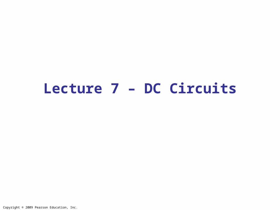
Chapter 26DC Circuits
Copyright © 2009 Pearson Education, Inc.
• EMF and Terminal Voltage
• Resistors in Series and in Parallel
• Kirchhoff’s Rules
• Series and Parallel EMFs; Battery Charging
• Circuits Containing Resistor and Capacitor (RC Circuits)
• Electric Hazards
• Ammeters and Voltmeters
•Wheatstone Bridge & Potentiometer
Units of Chapter 26

Copyright © 2009 Pearson Education, Inc.
Electric circuit needs battery or generator to produce current – these are called sources of emf.
Battery is a nearly constant voltage source, but does have a small internal resistance, which reduces the actual voltage from the ideal emf:
26-1 EMF and Terminal Voltage

Copyright © 2009 Pearson Education, Inc.
This resistance behaves as though it were in series with the emf.
26-1 EMF and Terminal Voltage
Copyright © 2009 Pearson Education, Inc.
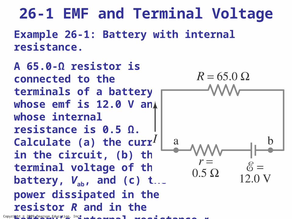
26-1 EMF and Terminal VoltageExample 26-1: Battery with internal resistance.
A 65.0-Ω resistor is connected to the terminals of a battery whose emf is 12.0 V and whose internal resistance is 0.5 Ω. Calculate (a) the current in the circuit, (b) the terminal voltage of the battery, Vab, and (c) the power dissipated in the resistor R and in the battery’s internal resistance r.
Copyright © 2009 Pearson Education, Inc.
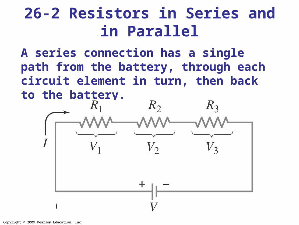
A series connection has a single path from the battery, through each circuit element in turn, then back to the battery.
26-2 Resistors in Series and in Parallel
Copyright © 2009 Pearson Education, Inc.
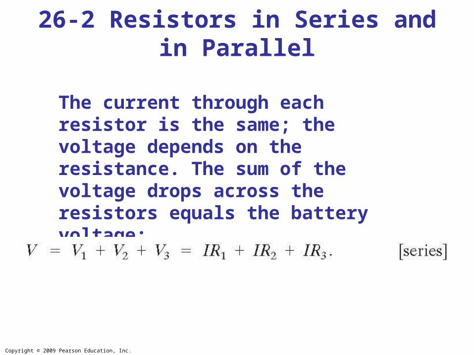
The current through each resistor is the same; the voltage depends on the resistance. The sum of the voltage drops across the resistors equals the battery voltage:
26-2 Resistors in Series and in Parallel
Copyright © 2009 Pearson Education, Inc.
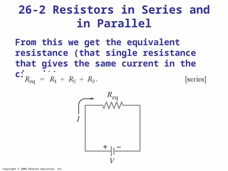
From this we get the equivalent resistance (that single resistance that gives the same current in the circuit):
26-2 Resistors in Series and in Parallel
Copyright © 2009 Pearson Education, Inc.
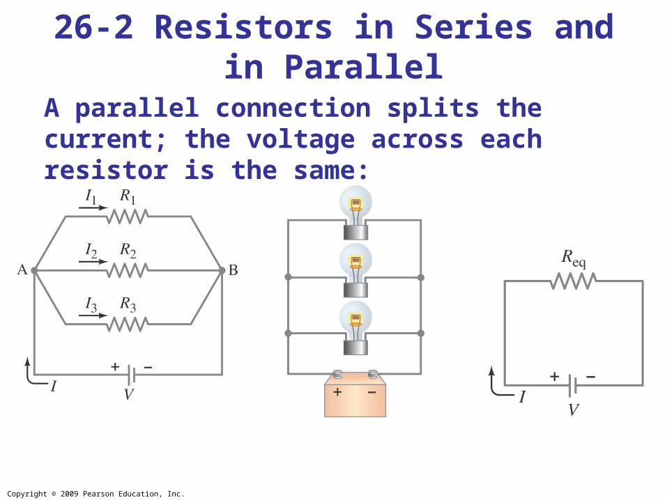
A parallel connection splits the current; the voltage across each resistor is the same:
26-2 Resistors in Series and in Parallel
Copyright © 2009 Pearson Education, Inc.
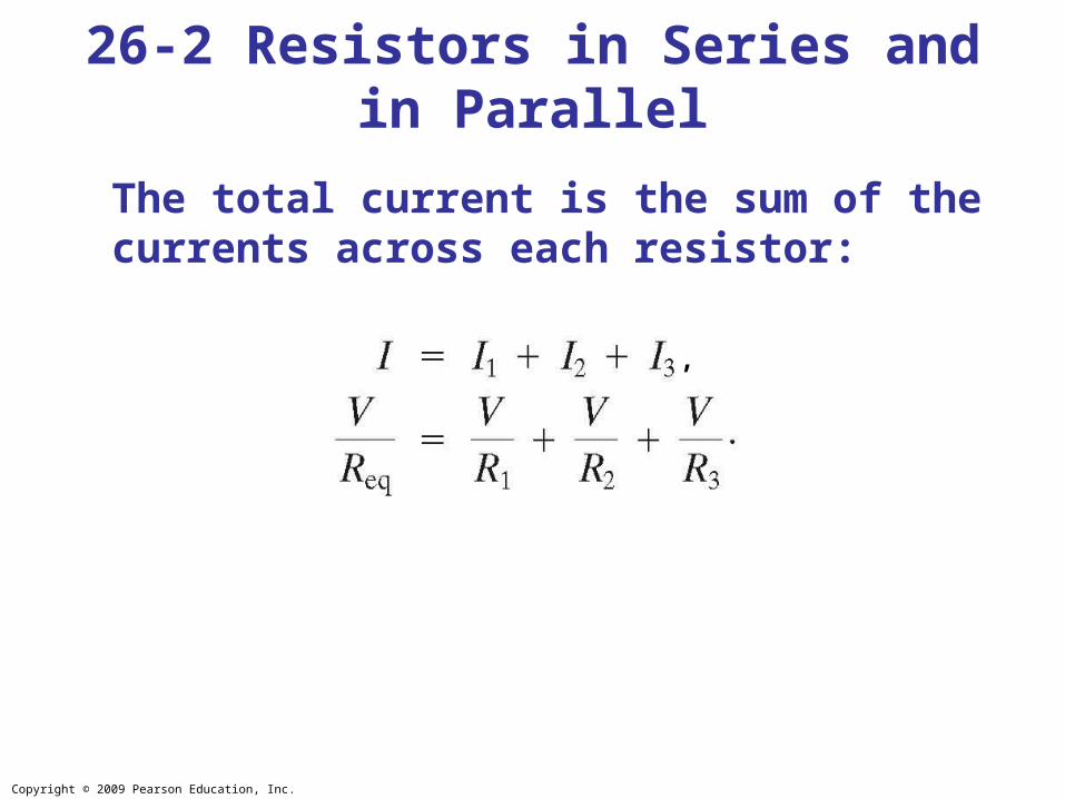
The total current is the sum of the currents across each resistor:
26-2 Resistors in Series and in Parallel
,
Copyright © 2009 Pearson Education, Inc.
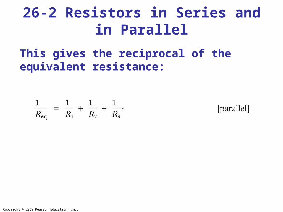
This gives the reciprocal of the equivalent resistance:
26-2 Resistors in Series and in Parallel
Copyright © 2009 Pearson Education, Inc.
26-2 Resistors in Series and in Parallel
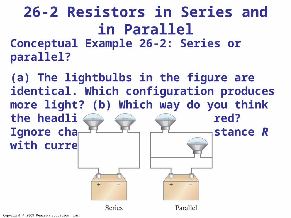
Conceptual Example 26-2: Series or parallel?
(a) The lightbulbs in the figure are identical. Which configuration produces more light? (b) Which way do you think the headlights of a car are wired? Ignore change of filament resistance R with current.
Copyright © 2009 Pearson Education, Inc.
26-2 Resistors in Series and in Parallel
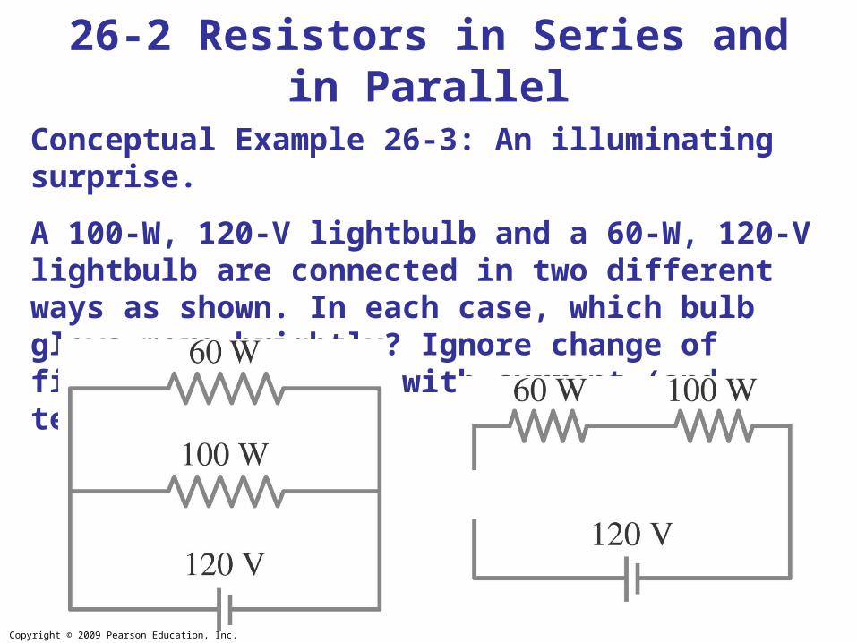
Conceptual Example 26-3: An illuminating surprise.
A 100-W, 120-V lightbulb and a 60-W, 120-V lightbulb are connected in two different ways as shown. In each case, which bulb glows more brightly? Ignore change of filament resistance with current (and temperature).
Copyright © 2009 Pearson Education, Inc.
26-2 Resistors in Series and in Parallel
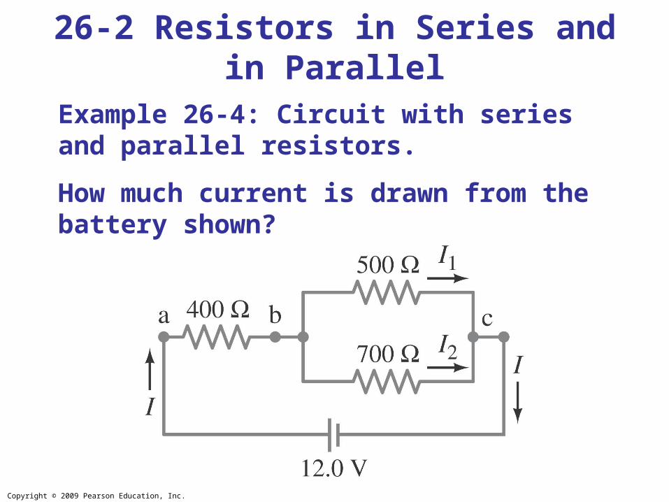
Example 26-4: Circuit with series and parallel resistors.
How much current is drawn from the battery shown?
Copyright © 2009 Pearson Education, Inc.
26-2 Resistors in Series and in Parallel
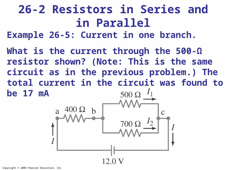
Example 26-5: Current in one branch.
What is the current through the 500-Ω resistor shown? (Note: This is the same circuit as in the previous problem.) The total current in the circuit was found to be 17 mA.
Copyright © 2009 Pearson Education, Inc.
26-2 Resistors in Series and in Parallel
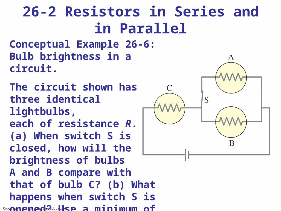
Conceptual Example 26-6: Bulb brightness in a circuit.
The circuit shown has three identical lightbulbs, each of resistance R. (a) When switch S is closed, how will the brightness of bulbs A and B compare with that of bulb C? (b) What happens when switch S is opened? Use a minimum of mathematics in your answers.

Copyright © 2009 Pearson Education, Inc.
26-2 Resistors in Series and in Parallel
Example 26-8: Analyzing a circuit.
A 9.0-V battery whose internal resistance r is 0.50 Ω is connected in the circuit shown. (a) How much current is drawn from the battery? (b) What is the terminal voltage of the battery? (c) What is the current in the 6.0-Ω resistor?
Copyright © 2009 Pearson Education, Inc.
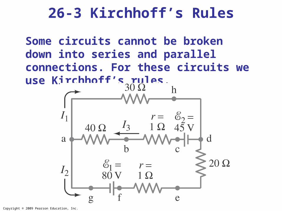
Some circuits cannot be broken down into series and parallel connections. For these circuits we use Kirchhoff’s rules.
26-3 Kirchhoff’s Rules

Copyright © 2009 Pearson Education, Inc.
Junction rule: The sum of currents entering a junction equals the sum of the currents leaving it.
26-3 Kirchhoff’s Rules
Copyright © 2009 Pearson Education, Inc.
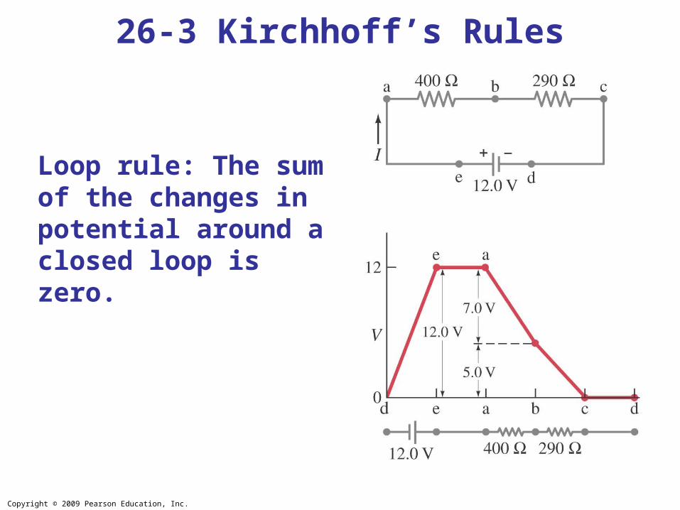
Loop rule: The sum of the changes in potential around a closed loop is zero.
26-3 Kirchhoff’s Rules
Copyright © 2009 Pearson Education, Inc.
Problem Solving: Kirchhoff’s Rules
1. Label each current, including its direction.
2. Identify unknowns.
3. Apply junction and loop rules; you will need as many independent equations as there are unknowns.
4.Solve the equations, being careful with signs. If the solution for a current is negative, that current is in the opposite direction from the one you have chosen.
26-3 Kirchhoff’s Rules

Copyright © 2009 Pearson Education, Inc.
26-3 Kirchhoff’s Rules
Example 26-9: Using Kirchhoff’s rules.
Calculate the currents I1, I2, and I3 in the three branches of the circuit in the figure.
Copyright © 2009 Pearson Education, Inc.
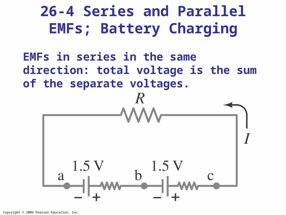
EMFs in series in the same direction: total voltage is the sum of the separate voltages.
26-4 Series and Parallel EMFs; Battery Charging

Copyright © 2009 Pearson Education, Inc.
EMFs in series, opposite direction: total voltage is the difference, but the lower-voltage battery is charged.
26-4 Series and Parallel EMFs; Battery Charging
Copyright © 2009 Pearson Education, Inc.
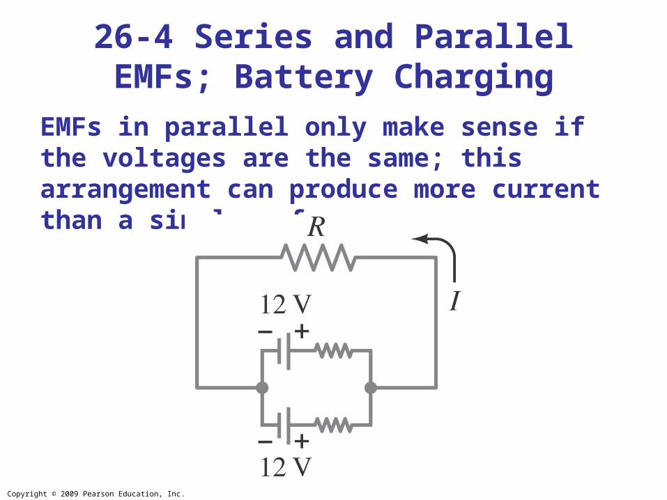
EMFs in parallel only make sense if the voltages are the same; this arrangement can produce more current than a single emf.
26-4 Series and Parallel EMFs; Battery Charging
Copyright © 2009 Pearson Education, Inc.
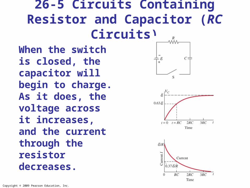
When the switch is closed, the capacitor will begin to charge. As it does, the voltage across it increases, and the current through the resistor decreases.
26-5 Circuits Containing Resistor and Capacitor (RC Circuits)

Copyright © 2009 Pearson Education, Inc.
26-5 Circuits Containing Resistor and Capacitor (RC Circuits)
To find the voltage as a function of time, we write the equation for the voltage changes around the loop:
Since Q = dI/dt, we can integrate to find the charge as a function of time:
Copyright © 2009 Pearson Education, Inc.
26-5 Circuits Containing Resistor and Capacitor (RC Circuits)
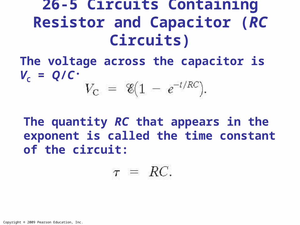
The voltage across the capacitor is VC = Q/C:
The quantity RC that appears in the exponent is called the time constant of the circuit:
Copyright © 2009 Pearson Education, Inc.
26-5 Circuits Containing Resistor and Capacitor (RC Circuits)
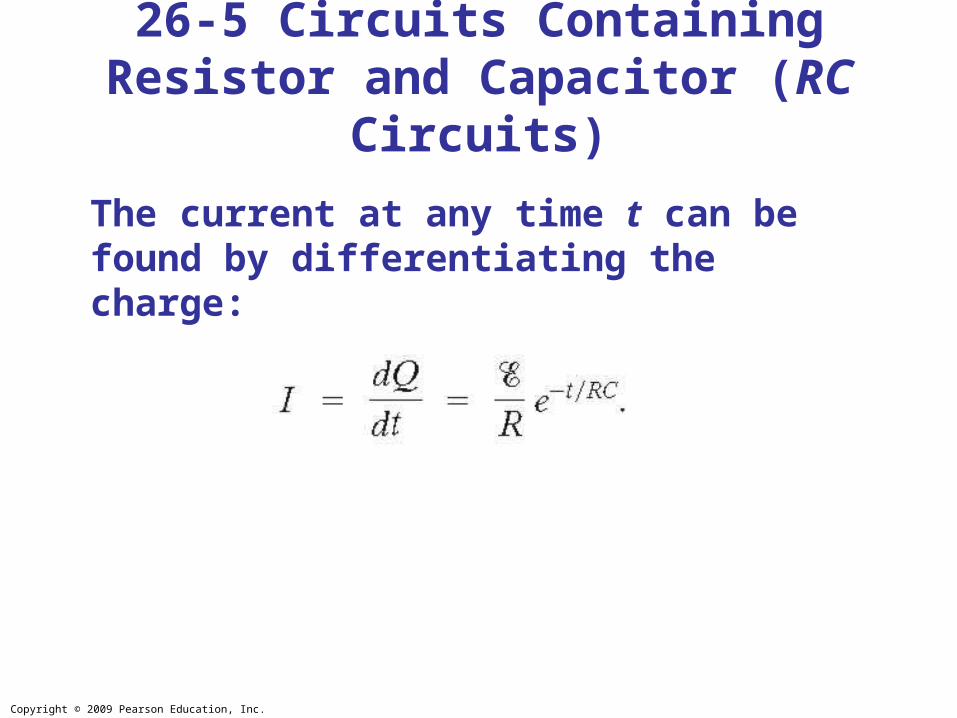
The current at any time t can be found by differentiating the charge:
Copyright © 2009 Pearson Education, Inc.
26-5 Circuits Containing Resistor and Capacitor (RC Circuits)
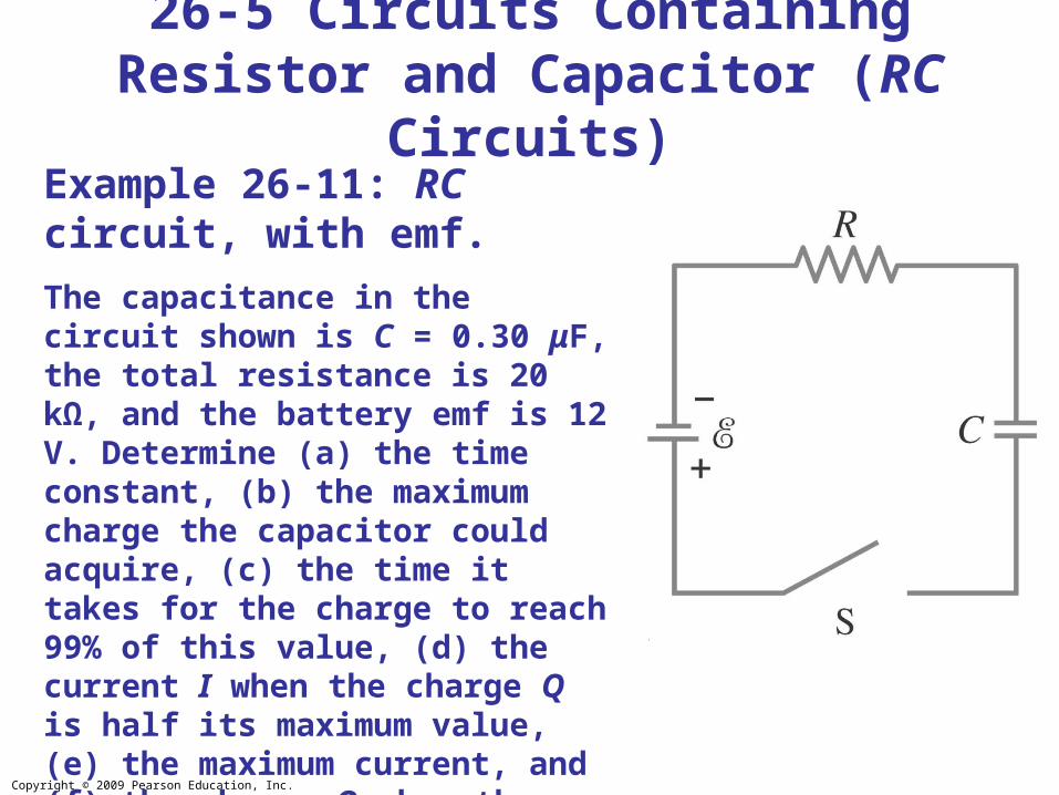
Example 26-11: RC circuit, with emf.
The capacitance in the circuit shown is C = 0.30 μF, the total resistance is 20 kΩ, and the battery emf is 12 V. Determine (a) the time constant, (b) the maximum charge the capacitor could acquire, (c) the time it takes for the charge to reach 99% of this value, (d) the current I when the charge Q is half its maximum value, (e) the maximum current, and (f) the charge Q when the current I is 0.20 its maximum value.

Copyright © 2009 Pearson Education, Inc.
If an isolated charged capacitor is connected across a resistor, it discharges:
26-5 Circuits Containing Resistor and Capacitor (RC Circuits)
Copyright © 2009 Pearson Education, Inc.
26-5 Circuits Containing Resistor and Capacitor (RC Circuits)
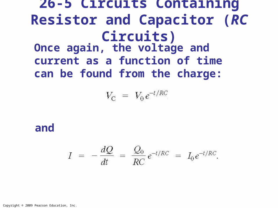
Once again, the voltage and current as a function of time can be found from the charge:
and
Copyright © 2009 Pearson Education, Inc.
26-5 Circuits Containing Resistor and Capacitor (RC Circuits)
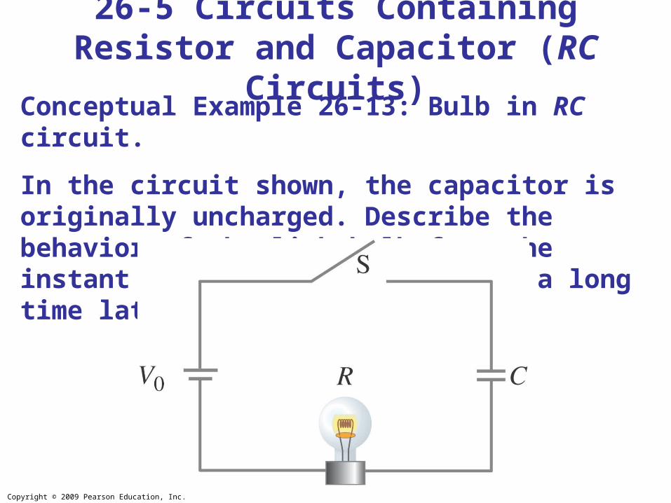
Conceptual Example 26-13: Bulb in RC circuit.
In the circuit shown, the capacitor is originally uncharged. Describe the behavior of the lightbulb from the instant switch S is closed until a long time later.
Copyright © 2009 Pearson Education, Inc.
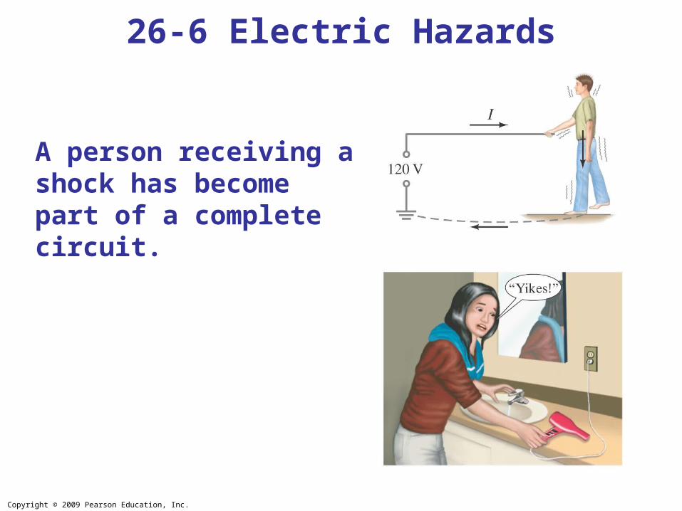
Most people can “feel” a current of 1 mA; a few mA of current begins to be painful. Currents above 10 mA may cause uncontrollable muscle contractions, making rescue difficult. Currents around 100 mA passing through the torso can cause death by ventricular fibrillation.
Higher currents may not cause fibrillation, but can cause severe burns.
Household voltage can be lethal if you are wet and in good contact with the ground. Be careful!
26-6 Electric Hazards
Copyright © 2009 Pearson Education, Inc.
A person receiving a shock has become part of a complete circuit.
26-6 Electric Hazards

Copyright © 2009 Pearson Education, Inc.
Faulty wiring and improper grounding can be hazardous. Make sure electrical work is done by a professional.
26-6 Electric Hazards
Copyright © 2009 Pearson Education, Inc.
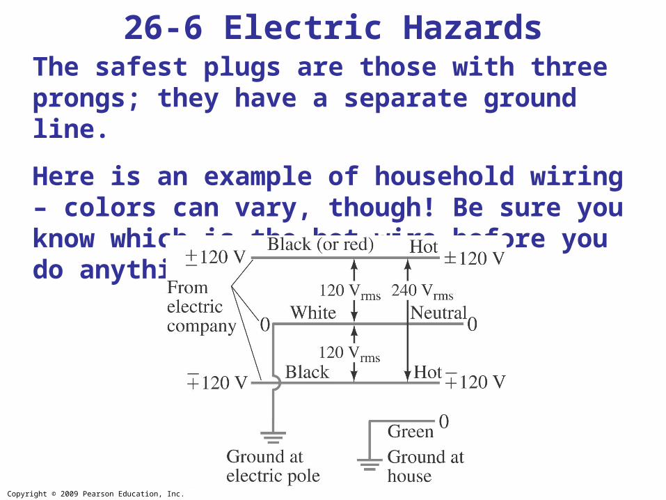
The safest plugs are those with three prongs; they have a separate ground line.
Here is an example of household wiring – colors can vary, though! Be sure you know which is the hot wire before you do anything.
26-6 Electric Hazards
Copyright © 2009 Pearson Education, Inc.
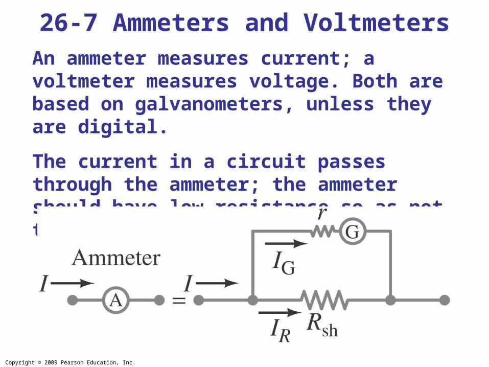
An ammeter measures current; a voltmeter measures voltage. Both are based on galvanometers, unless they are digital.
The current in a circuit passes through the ammeter; the ammeter should have low resistance so as not to affect the current.
26-7 Ammeters and Voltmeters
Copyright © 2009 Pearson Education, Inc.
26-7 Ammeters and Voltmeters
Example 26-15: Ammeter design.
Design an ammeter to read 1.0 A at full scale using a galvanometer with a full-scale sensitivity of 50 μA and a resistance r = 30 Ω. Check if the scale is linear.

Copyright © 2009 Pearson Education, Inc.
A voltmeter should not affect the voltage across the circuit element it is measuring; therefore its resistance should be very large.
26-7 Ammeters and Voltmeters
Copyright © 2009 Pearson Education, Inc.
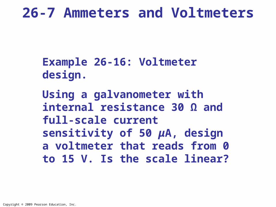
26-7 Ammeters and Voltmeters
Example 26-16: Voltmeter design.
Using a galvanometer with internal resistance 30 Ω and full-scale current sensitivity of 50 μA, design a voltmeter that reads from 0 to 15 V. Is the scale linear?

Copyright © 2009 Pearson Education, Inc.
An ohmmeter measures resistance; it requires a battery to provide a current.
26-7 Ammeters and Voltmeters
Copyright © 2009 Pearson Education, Inc.
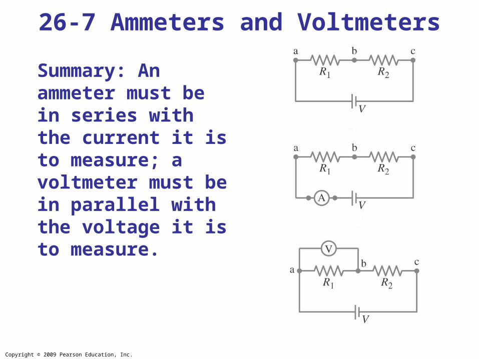
Summary: An ammeter must be in series with the current it is to measure; a voltmeter must be in parallel with the voltage it is to measure.
26-7 Ammeters and Voltmeters

Copyright © 2009 Pearson Education, Inc.
26-7 Ammeters and VoltmetersExample 26-17: Voltage reading vs. true voltage.
Suppose you are testing an electronic circuit which has two resistors, R1 and R2, each 15 kΩ, connected in series as shown in part (a) of the figure. The battery maintains 8.0 V across them and has negligible internal resistance. A voltmeter whose sensitivity is 10,000 Ω/V is put on the 5.0-V scale. What voltage does the meter read when connected across R1, part (b) of the figure, and what error is caused by the finite resistance of the meter?
Copyright © 2009 Pearson Education, Inc.
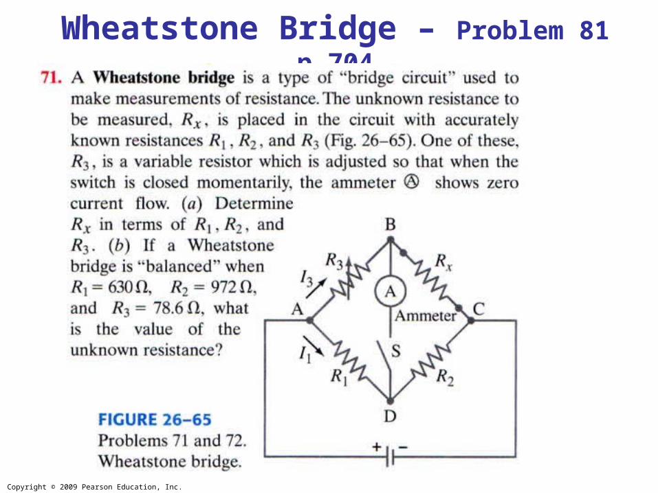
Wheatstone Bridge – Problem 81 p.704
Copyright © 2009 Pearson Education, Inc.
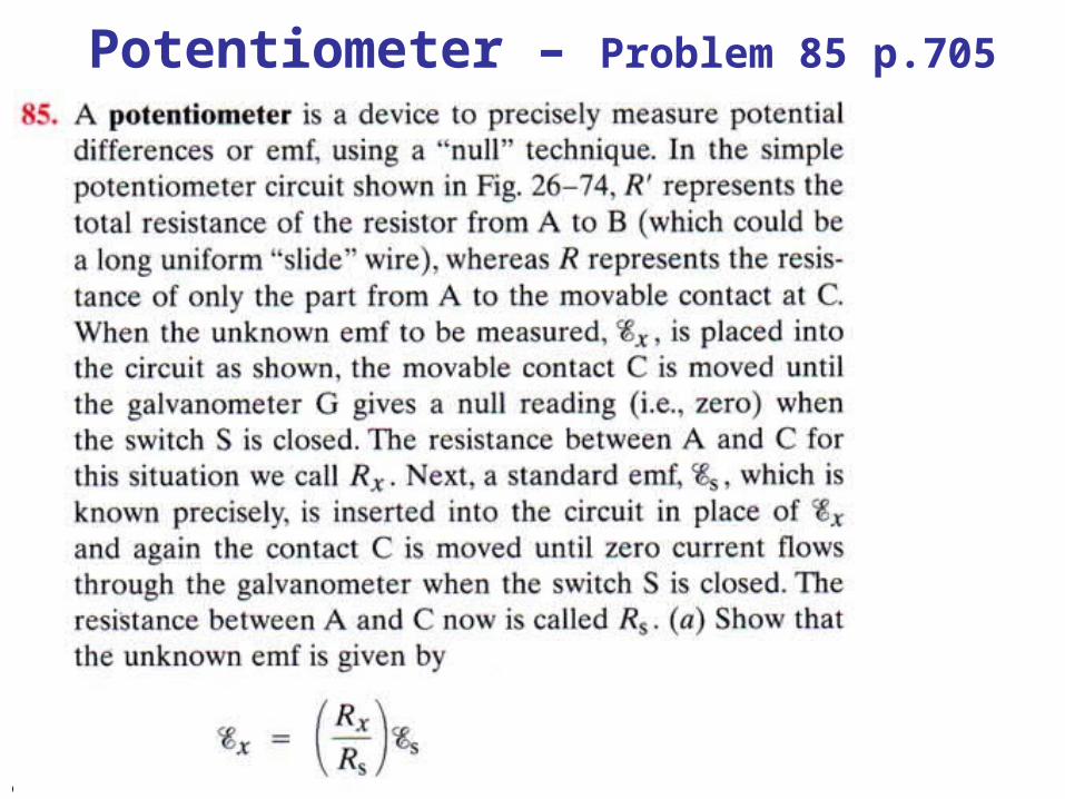
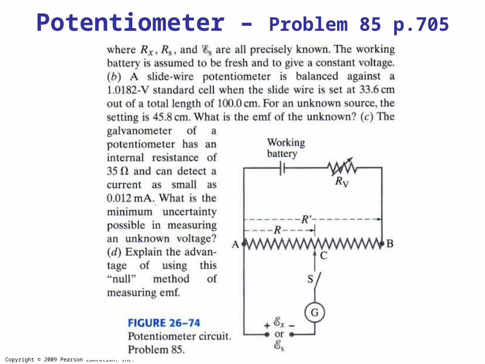
Potentiometer – Problem 85 p.705
Copyright © 2009 Pearson Education, Inc.
Potentiometer – Problem 85 p.705
Copyright © 2009 Pearson Education, Inc.
• A source of emf transforms energy from some other form to electrical energy.
• A battery is a source of emf in parallel with an internal resistance.
• Resistors in series:
Summary of Chapter 26
Copyright © 2009 Pearson Education, Inc.
• Resistors in parallel:
• Kirchhoff’s rules:
1.Sum of currents entering a junction equals sum of currents leaving it.
2.Total potential difference around closed loop is zero.
Summary of Chapter 26

Copyright © 2009 Pearson Education, Inc.
• RC circuit has a characteristic time constant:
• To avoid shocks, don’t allow your body to become part of a complete circuit.
• Ammeter: measures current.
• Voltmeter: measures voltage.
•Wheatstone bridge: measurement of resistance.
•Potentiometer: precise measurement of potential difference or emf by ‘null’ method.
Summary of Chapter 26