Embed Size (px)
Citation preview
Rekluse Motor Sports
E-Axle
2002+ Honda
2000-2002 KTMs
2004+ Kawasaki KXs
2004+ Suzuki RMZ 250
2002+ Yamaha YZs
Installation Guide
Copyright 2006 Rekluse Motor Sports E-Axle Revision 1.001
RMS 2710A, 2731A, 2741A, 2770A
195-2710B
Manual Revision: 032607
Rekluse Motor Sports, Inc.
110 E. 43rd Street
Boise, Idaho 83714
208-426-0659
2
Required Tools
10mm and 12mm sockets Needle Nose Pliers
Torque Wrench Wrench to remove stock axle
Flat Blade Screw Driver 4-mm or 6-mm Allen Key
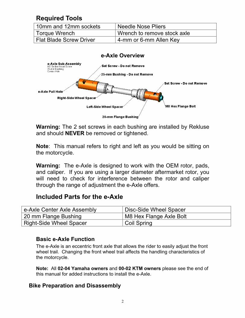
e-Axle Overview
Warning: The 2 set screws in each bushing are installed by Rekluse and should NEVER be removed or tightened. Note: This manual refers to right and left as you would be sitting on the motorcycle. Warning: The e-Axle is designed to work with the OEM rotor, pads, and caliper. If you are using a larger diameter aftermarket rotor, you will need to check for interference between the rotor and caliper through the range of adjustment the e-Axle offers.
Included Parts for the e-Axle
e-Axle Center Axle Assembly Disc-Side Wheel Spacer
20 mm Flange Bushing M8 Hex Flange Axle Bolt
Right-Side Wheel Spacer Coil Spring
Basic e-Axle Function
The e-Axle is an eccentric front axle that allows the rider to easily adjust the front wheel trail. Changing the front wheel trail affects the handling characteristics of the motorcycle. Note: All 02-04 Yamaha owners and 00-02 KTM owners please see the end of this manual for added instructions to install the e-Axle.
Bike Preparation and Disassembly
3
1. Place the motorcycle on a suitable stand so the front tire is no longer touching the ground.
2. Refer to your Owners Manual and remove the stock front axle and front wheel. Using a clean shop rag, remove all dirt and sand from the fork fists and from inside the wheel hub. Dirt and sand will mar the surface of your e-Axle parts. Stow the wheel in a suitable place so that the brake rotor cannot be damaged.
3. Disassemble the e-Axle. Remove the M8 Hex Flange Axle bolt from the end of the axle. Slide the 20-mm flange bushing off of the e-Axle sub-assembly followed by the left-side and right-side wheel spacers. Warning: The M8 set screws in each bushing are installed by Rekluse and should NEVER be removed or adjusted. The e-Axle Sub-Assembly consisting of the 25-mm bushing and the center axle are assembled by Rekluse and should NEVER be disassembled.
4
e-Axle Installation
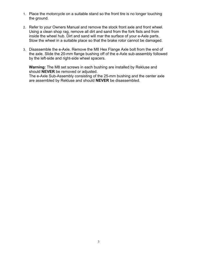
4. Slide the 20-mm Flanged Bushing into the disk-side fork fist to check fitment. The 20-mm Flanged Bushing should slide into the fork fist easily. On some bikes, the bushing may not slide in easily because the outer edge of the fork fist hole is not supported by the stock axle and after a few tightening cycles the fork fist hole will deform. Slide the flanged bushing into the left-side fork fist from both sides to validate this. To solve this, use some emery cloth and lightly sand the outer portion of the hole until the 20-mm Flanged Bushing slides in smoothly. See following pictures.
5. Remove the stock wheel spacers from both sides of the wheel hub. Use a clean rag to remove any dirt inside the seals and install both of the Rekluse wheel spacers.
Note: On all models except the Yamahas, the disk side wheel spacer is the longer of the two. On the 00-02 KTM, the wheel spacers are identical unless you will be installing the odometer replacement spacer.
6. Coat the center axle in a thin layer of grease to aid installing the axle. Note: You should coat the center axle in a thin layer of grease every time it is re-installed.
Disc Side
Spacer
Right Side
Spacer
5
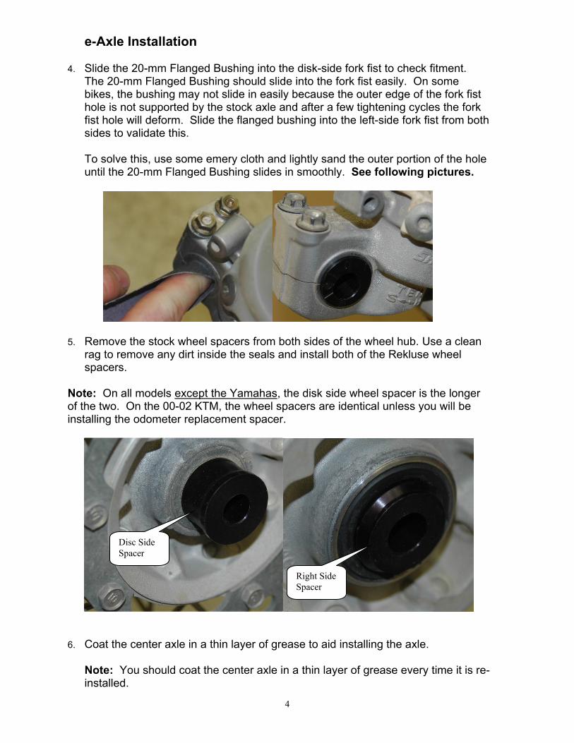
7. The next four steps will validate that the E-Axle Bushings are properly clamped
by the fork fists. Slide the axle assembly into the right-side fork fist.
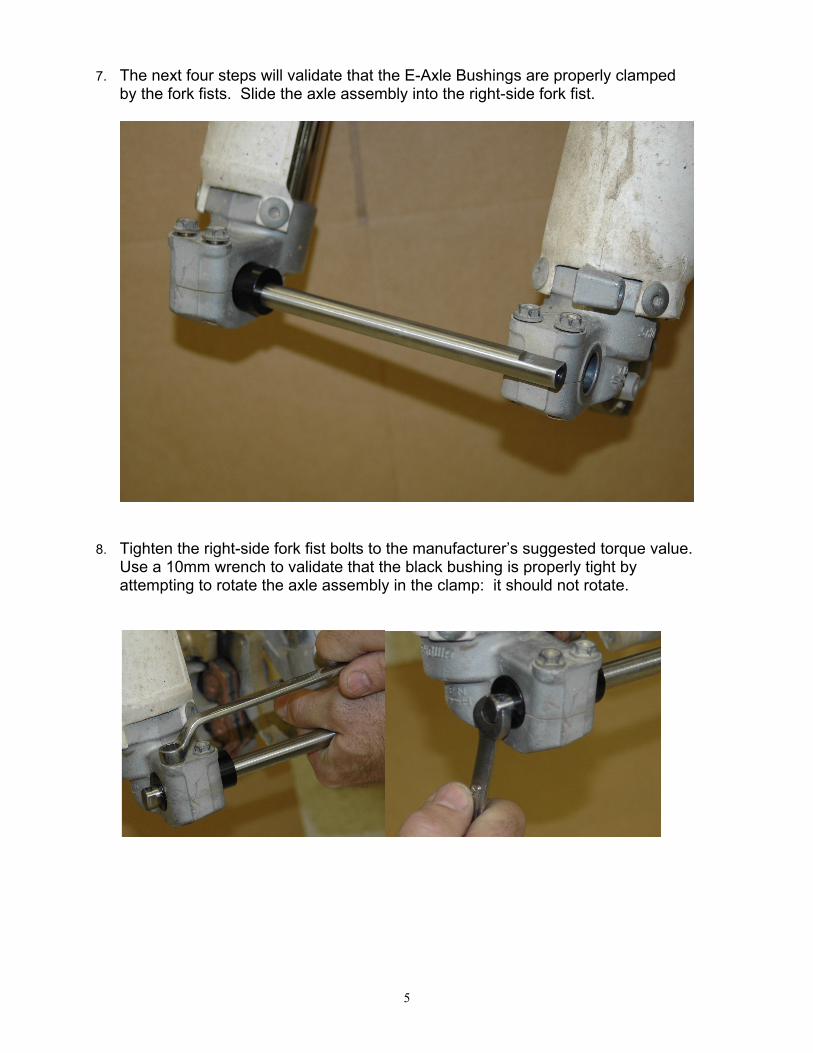
8. Tighten the right-side fork fist bolts to the manufacturer’s suggested torque value. Use a 10mm wrench to validate that the black bushing is properly tight by attempting to rotate the axle assembly in the clamp: it should not rotate.
6
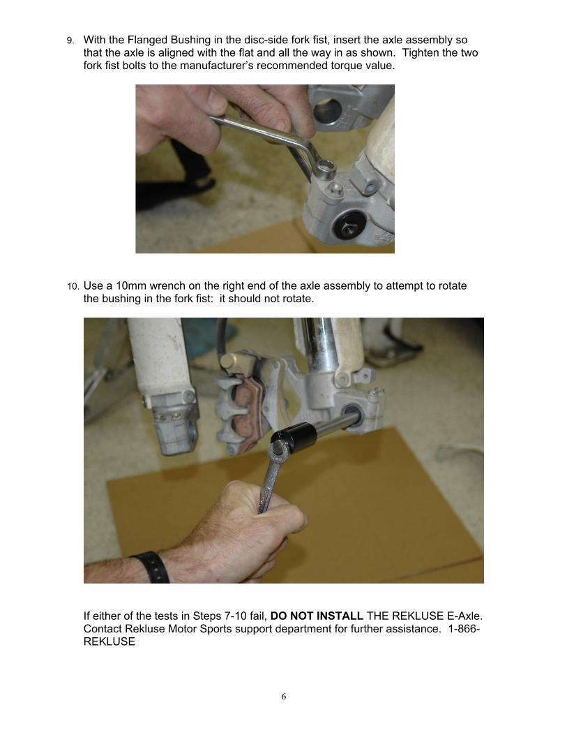
9. With the Flanged Bushing in the disc-side fork fist, insert the axle assembly so that the axle is aligned with the flat and all the way in as shown. Tighten the two fork fist bolts to the manufacturer’s recommended torque value.
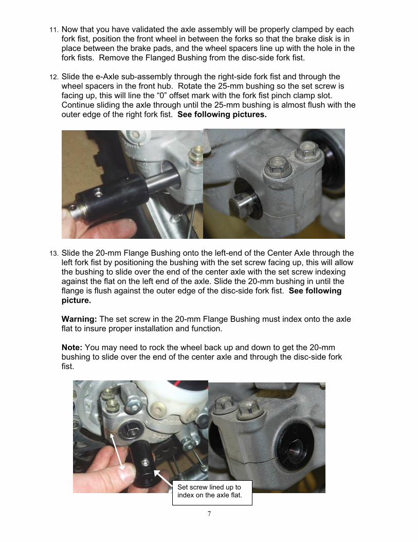
10. Use a 10mm wrench on the right end of the axle assembly to attempt to rotate the bushing in the fork fist: it should not rotate.
If either of the tests in Steps 7-10 fail, DO NOT INSTALL THE REKLUSE E-Axle. Contact Rekluse Motor Sports support department for further assistance. 1-866-REKLUSE
7
11. Now that you have validated the axle assembly will be properly clamped by each fork fist, position the front wheel in between the forks so that the brake disk is in place between the brake pads, and the wheel spacers line up with the hole in the fork fists. Remove the Flanged Bushing from the disc-side fork fist.
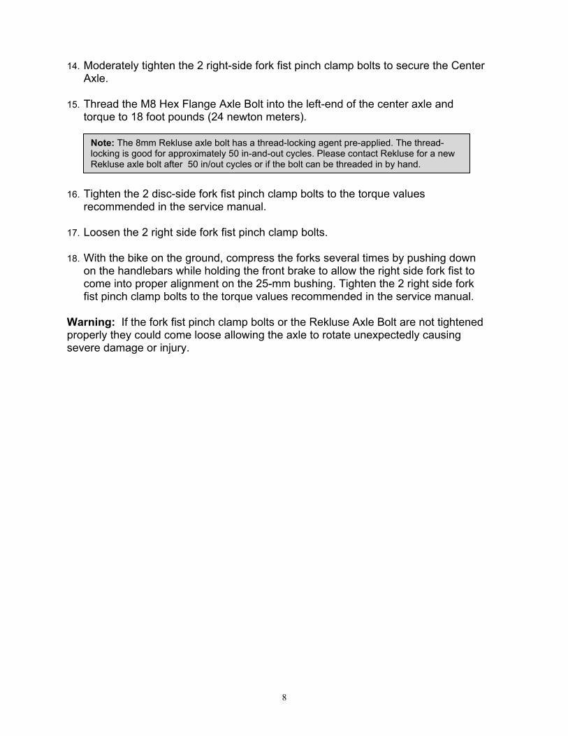
12. Slide the e-Axle sub-assembly through the right-side fork fist and through the wheel spacers in the front hub. Rotate the 25-mm bushing so the set screw is facing up, this will line the “0” offset mark with the fork fist pinch clamp slot. Continue sliding the axle through until the 25-mm bushing is almost flush with the outer edge of the right fork fist. See following pictures.
13. Slide the 20-mm Flange Bushing onto the left-end of the Center Axle through the left fork fist by positioning the bushing with the set screw facing up, this will allow the bushing to slide over the end of the center axle with the set screw indexing against the flat on the left end of the axle. Slide the 20-mm bushing in until the flange is flush against the outer edge of the disc-side fork fist. See following picture. Warning: The set screw in the 20-mm Flange Bushing must index onto the axle flat to insure proper installation and function.
Note: You may need to rock the wheel back up and down to get the 20-mm bushing to slide over the end of the center axle and through the disc-side fork fist.
Set screw lined up to index on the axle flat.
8
14. Moderately tighten the 2 right-side fork fist pinch clamp bolts to secure the Center Axle.
15. Thread the M8 Hex Flange Axle Bolt into the left-end of the center axle and torque to 18 foot pounds (24 newton meters).
16. Tighten the 2 disc-side fork fist pinch clamp bolts to the torque values recommended in the service manual.
17. Loosen the 2 right side fork fist pinch clamp bolts.
18. With the bike on the ground, compress the forks several times by pushing down on the handlebars while holding the front brake to allow the right side fork fist to come into proper alignment on the 25-mm bushing. Tighten the 2 right side fork fist pinch clamp bolts to the torque values recommended in the service manual.
Warning: If the fork fist pinch clamp bolts or the Rekluse Axle Bolt are not tightened properly they could come loose allowing the axle to rotate unexpectedly causing severe damage or injury.
Note: The 8mm Rekluse axle bolt has a thread-locking agent pre-applied. The thread-locking is good for approximately 50 in-and-out cycles. Please contact Rekluse for a new Rekluse axle bolt after 50 in/out cycles or if the bolt can be threaded in by hand.
9
Adjusting the e-Axle
1. Loosen the M8 Rekluse Axle bolt (10mm wrench/socket) on the disc-side of the e-Axle.
2. Loosen both right and left-side fork fist pinch clamp bolts.
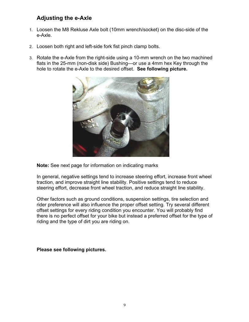
3. Rotate the e-Axle from the right-side using a 10-mm wrench on the two machined flats in the 25-mm (non-disk side) Bushing—or use a 4mm hex Key through the hole to rotate the e-Axle to the desired offset. See following picture.
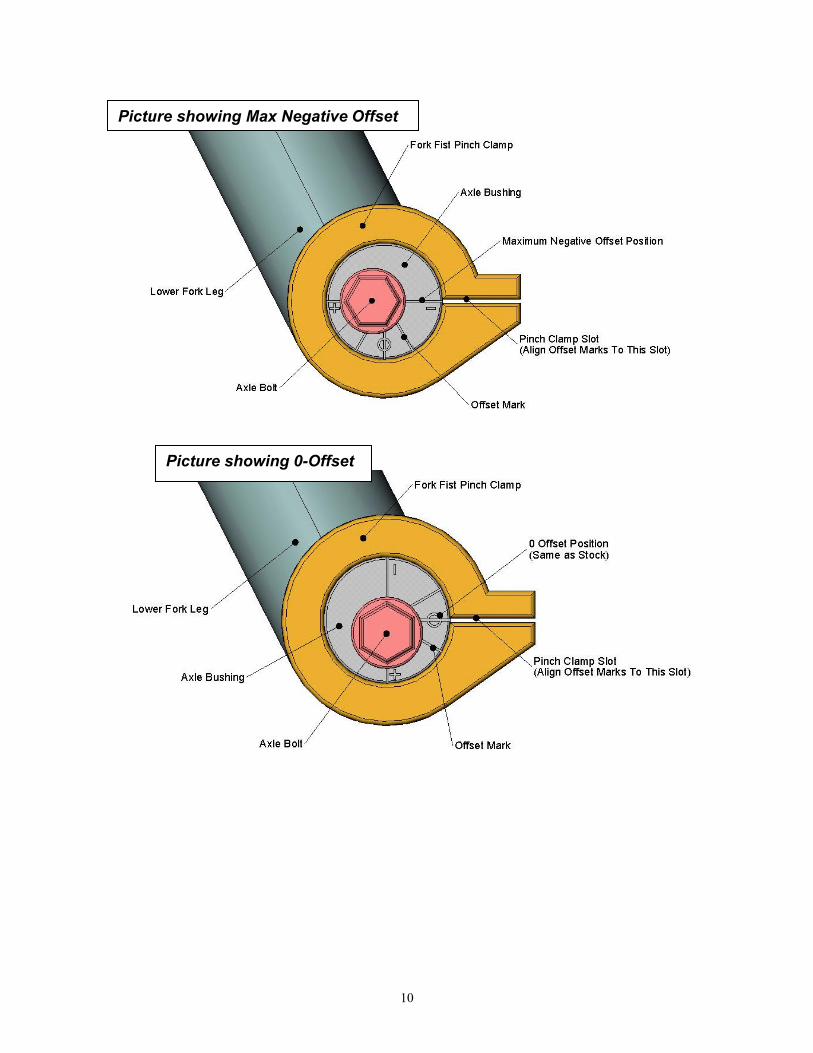
Note: See next page for information on indicating marks In general, negative settings tend to increase steering effort, increase front wheel traction, and improve straight line stability. Positive settings tend to reduce steering effort, decrease front wheel traction, and reduce straight line stability. Other factors such as ground conditions, suspension settings, tire selection and rider preference will also influence the proper offset setting. Try several different offset settings for every riding condition you encounter. You will probably find there is no perfect offset for your bike but instead a preferred offset for the type of riding and the type of dirt you are riding on. Please see following pictures.
10
Picture showing Max Negative Offset
Picture showing 0-Offset
11
4. Moderately tighten the 2 right-side fork fist pinch clamp bolts to secure the Center
Axle.
5. Thread the M8 Hex Flange Axle Bolt into the left-end of the center axle and torque to 18 foot pounds (24 newton meters).
6. Tighten the 2 disc-side fork fist pinch clamp bolts to the torque values recommended in the service manual.
7. Loosen the 2 right side fork fist pinch clamp bolts.
8. With the bike on the ground, compress the forks several times by pushing down on the handlebars while holding the front brake to allow the right side fork fist to come into proper alignment on the 25-mm bushing. Tighten the 2 right side fork fist pinch clamp bolts to the torque values recommended in the service manual.
Warning: If the fork fist pinch clamp bolts or the Rekluse Axle Bolt are not tightened properly they could come loose allowing the axle to rotate unexpectedly causing severe damage or injury. Note: When the axle is adjusted to the max negative position it is possible to introduce slight interference between the rotor and the leaf spring in the back of the caliper.
On most models there is usually no interference and if there is it is generally slight and will self clear. If the stock leaf spring installed behind the brake pads in the caliper rubs the rotor when the e-Axle is adjusted all the way back, you can
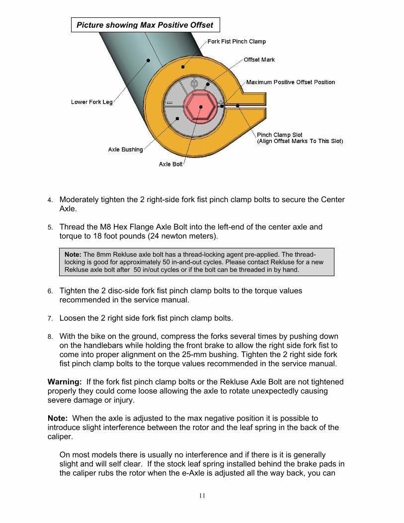
Picture showing Max Positive Offset
Note: The 8mm Rekluse axle bolt has a thread-locking agent pre-applied. The thread-locking is good for approximately 50 in-and-out cycles. Please contact Rekluse for a new Rekluse axle bolt after 50 in/out cycles or if the bolt can be threaded in by hand.
12
remove it and replace with the included coil spring. See the “Coil Spring Installation” section at the end of this manual.
Axle Removal
1. Place the motorcycle on a suitable stand.
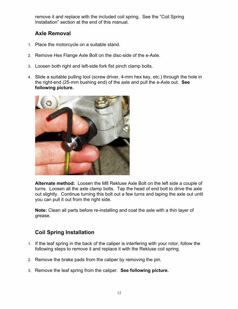
2. Remove Hex Flange Axle Bolt on the disc-side of the e-Axle. 3. Loosen both right and left-side fork fist pinch clamp bolts. 4. Slide a suitable pulling tool (screw driver, 4-mm hex key, etc.) through the hole in
the right-end (25-mm bushing end) of the axle and pull the e-Axle out. See following picture.
Alternate method: Loosen the M8 Rekluse Axle Bolt on the left side a couple of turns. Loosen all the axle clamp bolts. Tap the head of end bolt to drive the axle out slightly. Continue turning this bolt out a few turns and taping the axle out until you can pull it out from the right side. Note: Clean all parts before re-installing and coat the axle with a thin layer of grease.
Coil Spring Installation
1. If the leaf spring in the back of the caliper is interfering with your rotor, follow the following steps to remove it and replace it with the Rekluse coil spring.
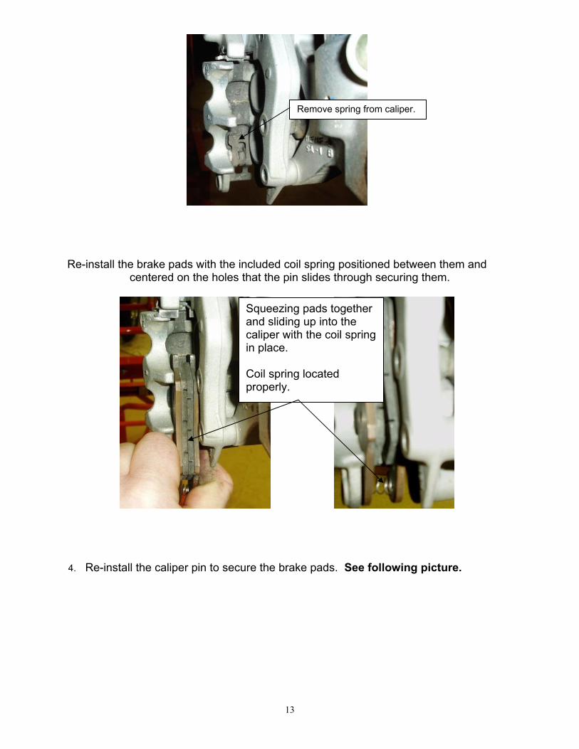
2. Remove the brake pads from the caliper by removing the pin. 3. Remove the leaf spring from the caliper. See following picture.
13
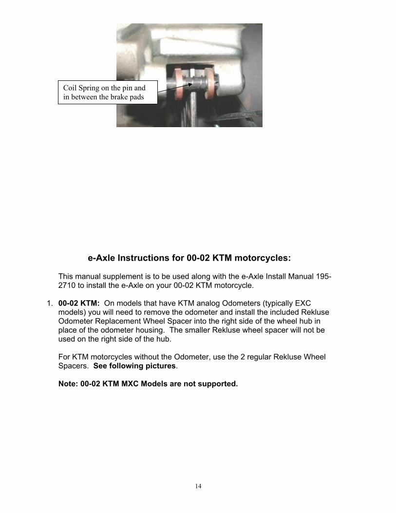
Re-install the brake pads with the included coil spring positioned between them and centered on the holes that the pin slides through securing them.
4. Re-install the caliper pin to secure the brake pads. See following picture.
Remove spring from caliper.
Squeezing pads together and sliding up into the caliper with the coil spring in place. Coil spring located properly.
14
e-Axle Instructions for 00-02 KTM motorcycles: This manual supplement is to be used along with the e-Axle Install Manual 195-2710 to install the e-Axle on your 00-02 KTM motorcycle.
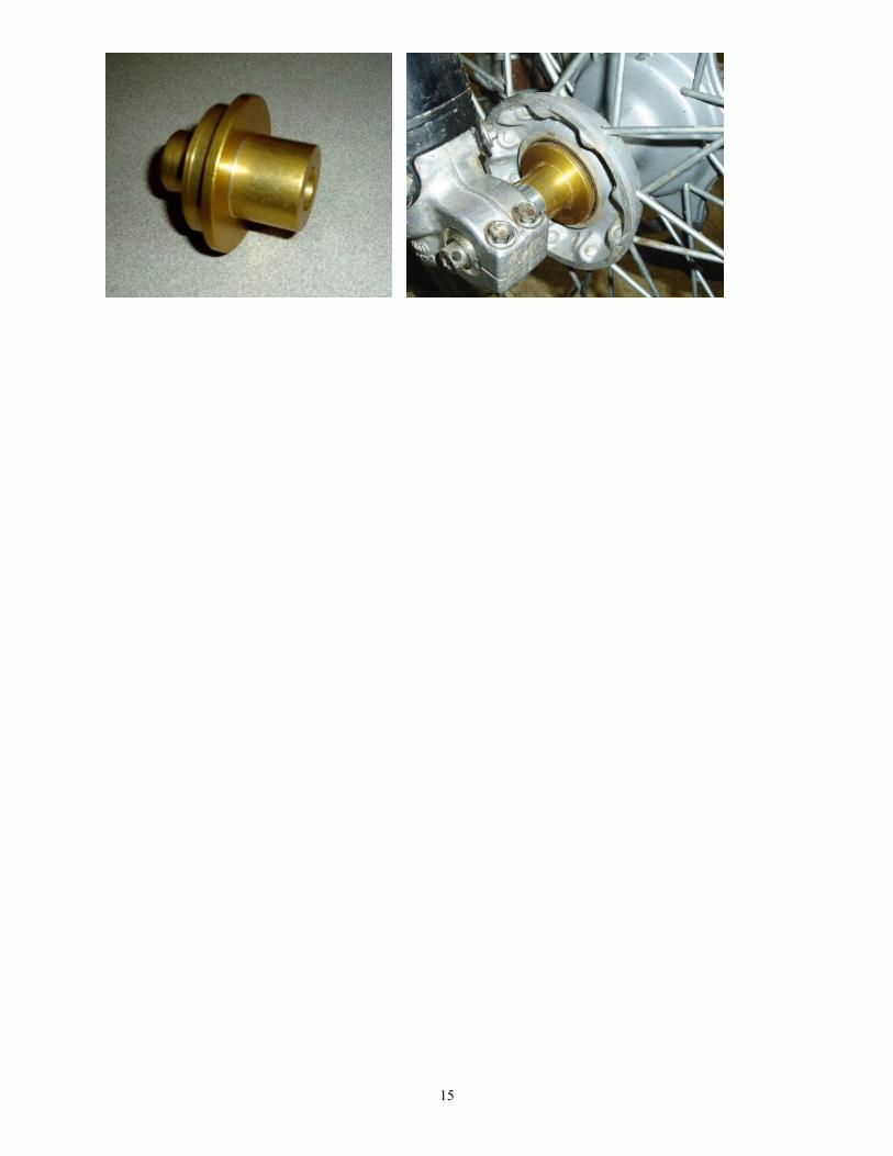
1. 00-02 KTM: On models that have KTM analog Odometers (typically EXC models) you will need to remove the odometer and install the included Rekluse Odometer Replacement Wheel Spacer into the right side of the wheel hub in place of the odometer housing. The smaller Rekluse wheel spacer will not be used on the right side of the hub.
For KTM motorcycles without the Odometer, use the 2 regular Rekluse Wheel Spacers. See following pictures. Note: 00-02 KTM MXC Models are not supported.
Coil Spring on the pin and
in between the brake pads
15
16
e-Axle Instructions for 02-04 Yamaha motorcycles: This manual supplement is to be used along with the e-Axle Install Manual 195-2710 to install the e-Axle on your 02-04 Yamaha motorcycle.
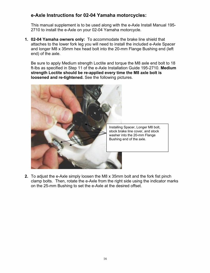
1. 02-04 Yamaha owners only: To accommodate the brake line shield that attaches to the lower fork leg you will need to install the included e-Axle Spacer and longer M8 x 35mm hex head bolt into the 20-mm Flange Bushing end (left end) of the axle.
Be sure to apply Medium strength Loctite and torque the M8 axle end bolt to 18 ft-lbs as specified in Step 11 of the e-Axle Installation Guide 195-2710. Medium strength Loctite should be re-applied every time the M8 axle bolt is loosened and re-tightened. See the following pictures.
2. To adjust the e-Axle simply loosen the M8 x 35mm bolt and the fork fist pinch clamp bolts. Then, rotate the e-Axle from the right side using the indicator marks on the 25-mm Bushing to set the e-Axle at the desired offset.
Installing Spacer, Longer M8 bolt, stock brake line cover, and stock washer into the 20-mm Flange Bushing end of the axle.