Embed Size (px)
Citation preview
Copyright 2005 John Wiley & Sons, Inc 3 - 1
Physical and Data Physical and Data Link LayersLink Layers
Copyright 2005 John Wiley & Sons, Inc 3 - 2
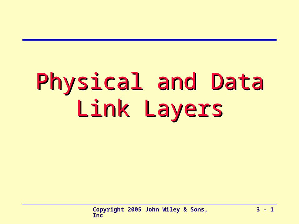
Physical Layer - Overview
• Includes network hardware and circuits
• Network circuits: – physical media (e.g., cables) and
– special purposes devices (e.g., routers and hubs).
• Types of Circuits – Physical circuits connect devices & include actual wires
such as twisted pair wires
– Logical circuits refer to the transmission characteristics of the circuit, such as a T-1 connection refers to 1.5 Mbps
– Can be the same or different. For example, in multiplexing, one wire carries several logical circuits
Physical Layer
Network Layer
Data Link Layer
Copyright 2005 John Wiley & Sons, Inc 3 - 3
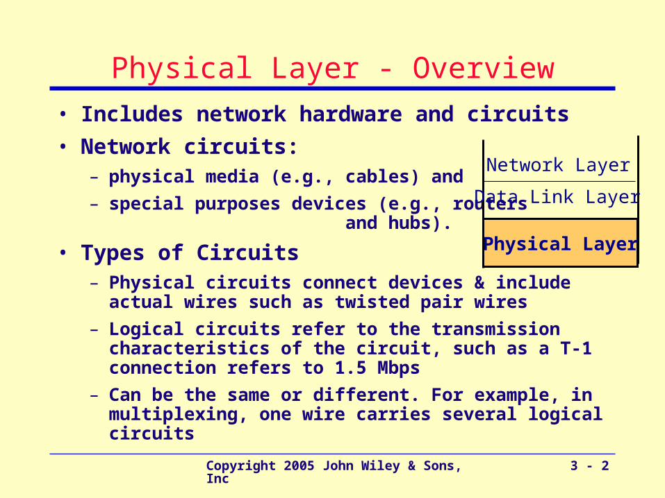
Types of Data Transmitted
• Analog data
– Produced by telephones
– Sound waves, which vary continuously over time
– Can take on any value in a wide range of possibilities
• Digital data
– Produced by computers, in binary form, represented as a series of ones and zeros
– Can take on only 0 ad 1
Copyright 2005 John Wiley & Sons, Inc 3 - 4
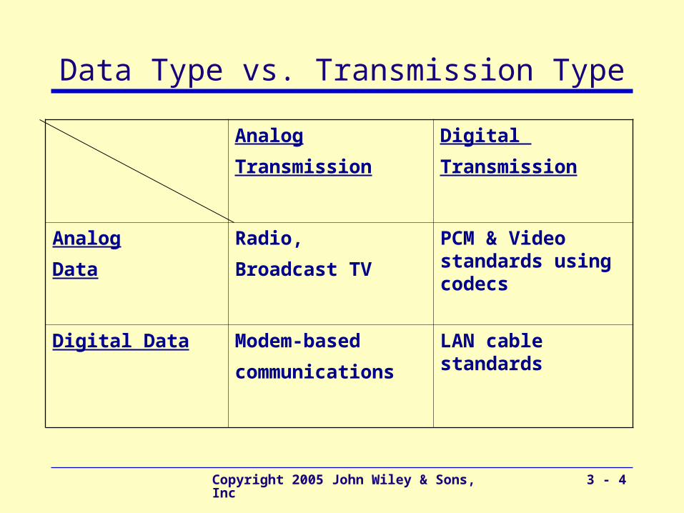
Data Type vs. Transmission Type
Analog
Transmission
Digital
Transmission
Analog
Data
Radio,
Broadcast TV
PCM & Video standards using codecs
Digital Data Modem-based
communications
LAN cable standards
Copyright 2005 John Wiley & Sons, Inc 3 - 5
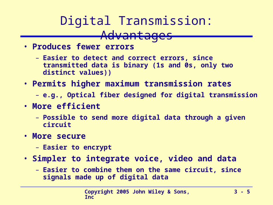
Digital Transmission: Advantages
• Produces fewer errors– Easier to detect and correct errors, since transmitted data
is binary (1s and 0s, only two distinct values))
• Permits higher maximum transmission rates– e.g., Optical fiber designed for digital transmission
• More efficient– Possible to send more digital data through a given circuit
• More secure– Easier to encrypt
• Simpler to integrate voice, video and data – Easier to combine them on the same circuit, since signals
made up of digital data

Copyright 2005 John Wiley & Sons, Inc 3 - 6
Point-to-Point Configuration
– Used when computers generate enough data to fill the capacity of the circuit
– Each computer has its own circuit to any other computer in the network (expensive)
Copyright 2005 John Wiley & Sons, Inc 3 - 7
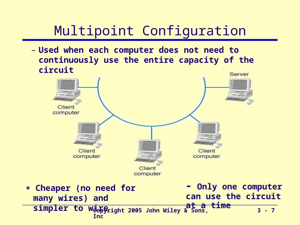
Multipoint Configuration
+ Cheaper (no need for many wires) and simpler to wire
- Only one computer can use the circuit at a time
– Used when each computer does not need to continuously use the entire capacity of the circuit
Copyright 2005 John Wiley & Sons, Inc 3 - 8
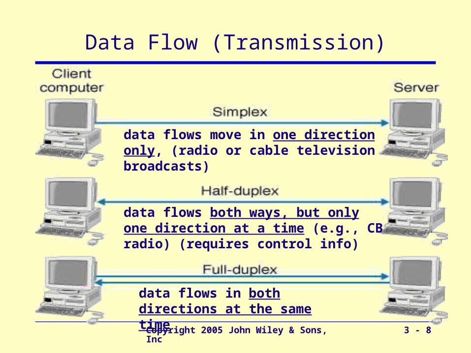
Data Flow (Transmission)
data flows move in one direction only, (radio or cable television broadcasts)
data flows both ways, but only one direction at a time (e.g., CB radio) (requires control info)
data flows in both directions at the same time
Copyright 2005 John Wiley & Sons, Inc 3 - 9
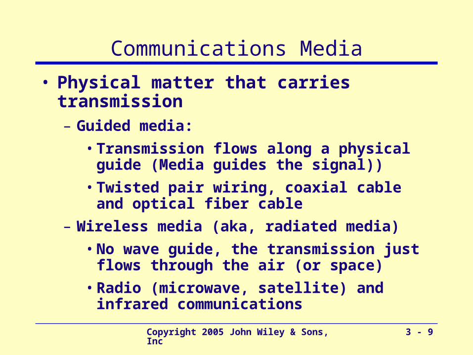
Communications Media
• Physical matter that carries transmission– Guided media:
• Transmission flows along a physical guide (Media guides the signal))
• Twisted pair wiring, coaxial cable and optical fiber cable
– Wireless media (aka, radiated media)
• No wave guide, the transmission just flows through the air (or space)
• Radio (microwave, satellite) and infrared communications

Copyright 2005 John Wiley & Sons, Inc 3 - 10
Twisted Pair (TP) Wires
• Commonly used for telephones and LANs
• Reduced electromagnetic interference– Via twisting two wires together
(Usually several twists per inch)
• TP cables have a number of pairs of wires– Telephone lines: two pairs (4 wires, usually only one
pair is used by the telephone)
– LAN cables: 4 pairs (8 wires)
• Also used in telephone trunk lines (up to several thousand pairs)
• Shielded twisted pair also exists, but is more expensive
Copyright 2005 John Wiley & Sons, Inc 3 - 11
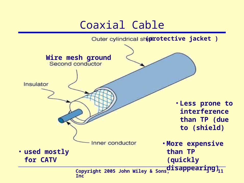
Coaxial Cable
Wire mesh ground
(protective jacket )
• More expensive than TP (quickly disappearing)
• used mostly for CATV
• Less prone to interference than TP (due to (shield)
Copyright 2005 John Wiley & Sons, Inc 3 - 12
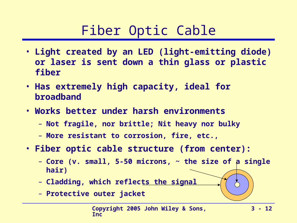
Fiber Optic Cable
• Light created by an LED (light-emitting diode) or laser is sent down a thin glass or plastic fiber
• Has extremely high capacity, ideal for broadband
• Works better under harsh environments– Not fragile, nor brittle; Nit heavy nor bulky
– More resistant to corrosion, fire, etc.,
• Fiber optic cable structure (from center):– Core (v. small, 5-50 microns, ~ the size of a single hair)
– Cladding, which reflects the signal
– Protective outer jacket
Copyright 2005 John Wiley & Sons, Inc 3 - 13
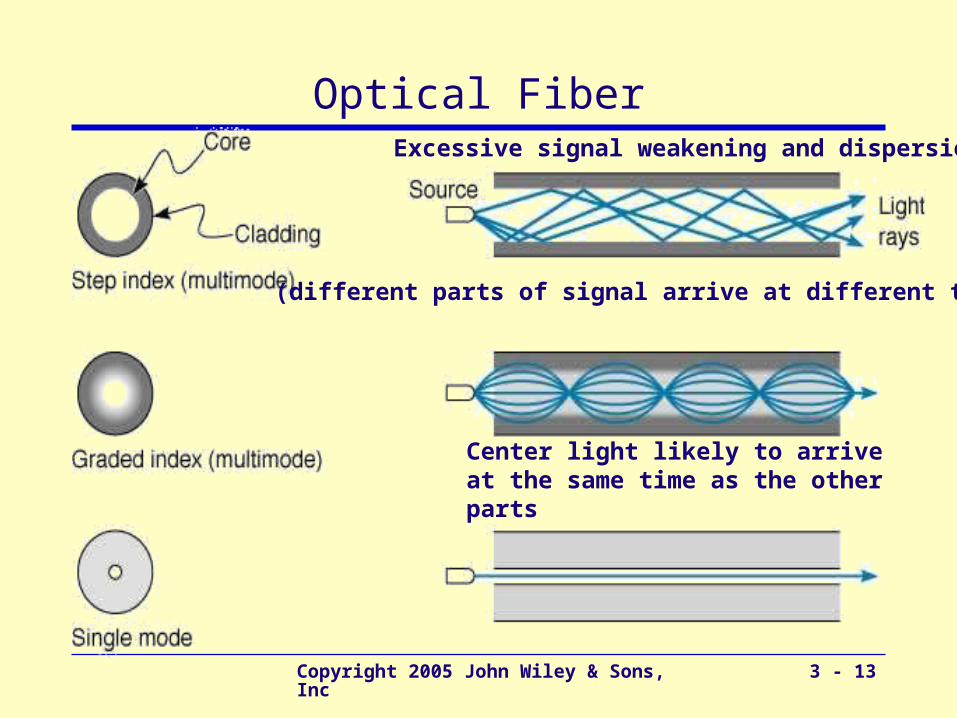
Optical Fiber
(different parts of signal arrive at different times)
Excessive signal weakening and dispersion
Center light likely to arrive at the same time as the other parts
Copyright 2005 John Wiley & Sons, Inc 3 - 14
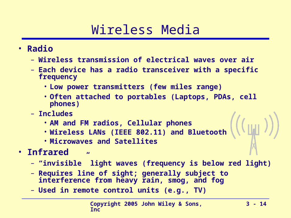
• Radio– Wireless transmission of electrical waves over air– Each device has a radio transceiver with a specific frequency
• Low power transmitters (few miles range)• Often attached to portables (Laptops, PDAs, cell phones)
– Includes • AM and FM radios, Cellular phones• Wireless LANs (IEEE 802.11) and Bluetooth• Microwaves and Satellites
• Infrared– “invisible” light waves (frequency is below red light)– Requires line of sight; generally subject to interference from
heavy rain, smog, and fog– Used in remote control units (e.g., TV)
Wireless Media
Copyright 2005 John Wiley & Sons, Inc 3 - 15
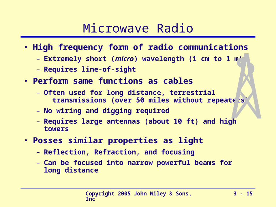
Microwave Radio
• High frequency form of radio communications– Extremely short (micro) wavelength (1 cm to 1 m)
– Requires line-of-sight
• Perform same functions as cables– Often used for long distance, terrestrial
transmissions (over 50 miles without repeaters)
– No wiring and digging required
– Requires large antennas (about 10 ft) and high towers
• Posses similar properties as light– Reflection, Refraction, and focusing
– Can be focused into narrow powerful beams for long distance
Copyright 2005 John Wiley & Sons, Inc 3 - 16
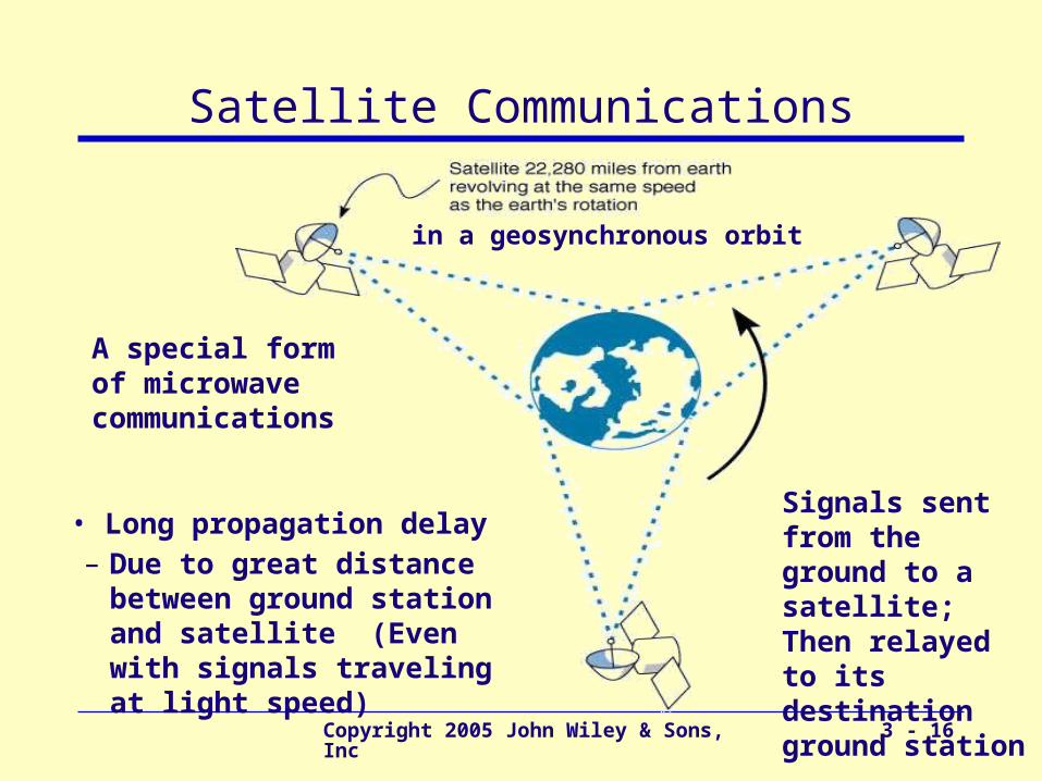
Satellite Communications
A special form of microwave communications
in a geosynchronous orbit
Signals sent from the ground to a satellite; Then relayed to its destination ground station
• Long propagation delay – Due to great distance
between ground station and satellite (Even with signals traveling at light speed)
Copyright 2005 John Wiley & Sons, Inc 3 - 17
Digital Transmission of Digital Data
• Computers produce binary data
• Standards needed to ensure both sender and receiver understands this data
– Coding: language that computers use to represent letters, numbers, and symbols in a message
– Signaling (aka, encoding): language that computers use to represent bits (0 or 1) in electrical voltage
• Bits in a message can be send in
– A single wire one after another (Serial transmission)
– Multiple wires simultaneously (Parallel transmission)
Copyright 2005 John Wiley & Sons, Inc 3 - 18
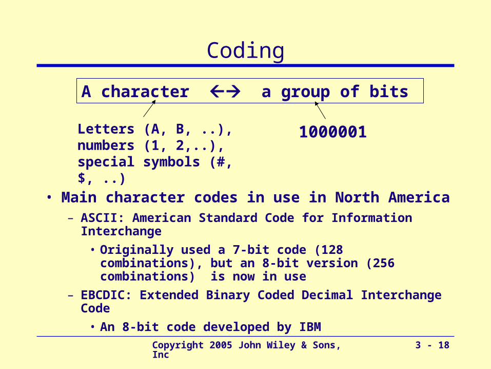
Coding
• Main character codes in use in North America– ASCII: American Standard Code for Information
Interchange
• Originally used a 7-bit code (128 combinations), but an 8-bit version (256 combinations) is now in use
– EBCDIC: Extended Binary Coded Decimal Interchange Code
• An 8-bit code developed by IBM
A character a group of bits
Letters (A, B, ..), numbers (1, 2,..),special symbols (#, $, ..)
1000001

Copyright 2005 John Wiley & Sons, Inc 3 - 19
Transmission Modes
• Parallel mode
– Uses several wires, each wire sending one bit at the same time as the others
• A parallel printer cable sends 8 bits together
• Computer’s processor and motherboard also use parallel busses (8 bits, 16 bits, 32 bits) to move data around
• Serial Mode
– Sends bit by bit over a single wire
– Serial mode is slower than parallel mode
Copyright 2005 John Wiley & Sons, Inc 3 - 20
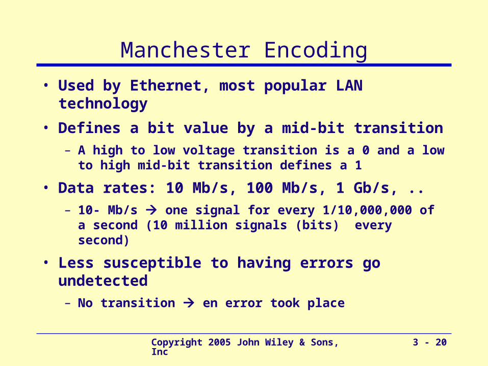
Manchester Encoding
• Used by Ethernet, most popular LAN technology
• Defines a bit value by a mid-bit transition– A high to low voltage transition is a 0 and a low to high
mid-bit transition defines a 1
• Data rates: 10 Mb/s, 100 Mb/s, 1 Gb/s, ..– 10- Mb/s one signal for every 1/10,000,000 of a
second (10 million signals (bits) every second)
• Less susceptible to having errors go undetected– No transition en error took place

Copyright 2005 John Wiley & Sons, Inc 3 - 21
Digital Transmission Types
Unipolar
BipolarNRZ
BipolarRZ
Manchester
Copyright 2005 John Wiley & Sons, Inc 3 - 22
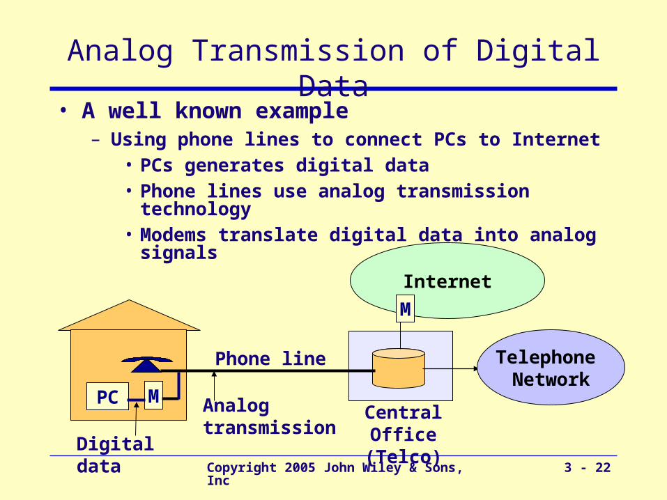
Analog Transmission of Digital Data• A well known example
– Using phone lines to connect PCs to Internet• PCs generates digital data• Phone lines use analog transmission technology• Modems translate digital data into analog signals
Phone line
Central Office(Telco)
Analog transmission
PC M
Telephone Network
Internet
Digital data
M

Copyright 2005 John Wiley & Sons, Inc 3 - 23
Telephone Network
• Originally designed for human speech (analog communications) only
• POTS (Plain Old Telephone Service)– Enables voice communications between two telephones
– Human voice (sound waves) converted to electrical signals by the sending telephone
– Signals travel through POTS and converted back to sound waves
• Sending digital data over POTS– Use modems to convert digital data to an analog format
• One modem used by sender to produce analog data
• Another modem used by receiver to regenerate digital data
Copyright 2005 John Wiley & Sons, Inc 3 - 24
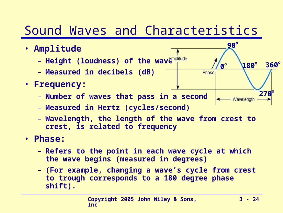
Sound Waves and Characteristics• Amplitude
– Height (loudness) of the wave
– Measured in decibels (dB)
• Frequency: – Number of waves that pass in a second
– Measured in Hertz (cycles/second)
– Wavelength, the length of the wave from crest to crest, is related to frequency
• Phase: – Refers to the point in each wave cycle at which the wave
begins (measured in degrees)
– (For example, changing a wave’s cycle from crest to trough corresponds to a 180 degree phase shift).
0o
90o
360o180o
270o

Copyright 2005 John Wiley & Sons, Inc 3 - 25
Wavelength vs. Frequency
λ
v = f λ
v = 3 x10⁸ m/s = 300,000 km/s = 186,000 miles/s
Example: if f = 900 MHz
λ = 3 x10⁸ / 900 x 10 3
= 3/9 = 0.3 meters
speed = frequency * wavelength
Copyright 2005 John Wiley & Sons, Inc 3 - 26
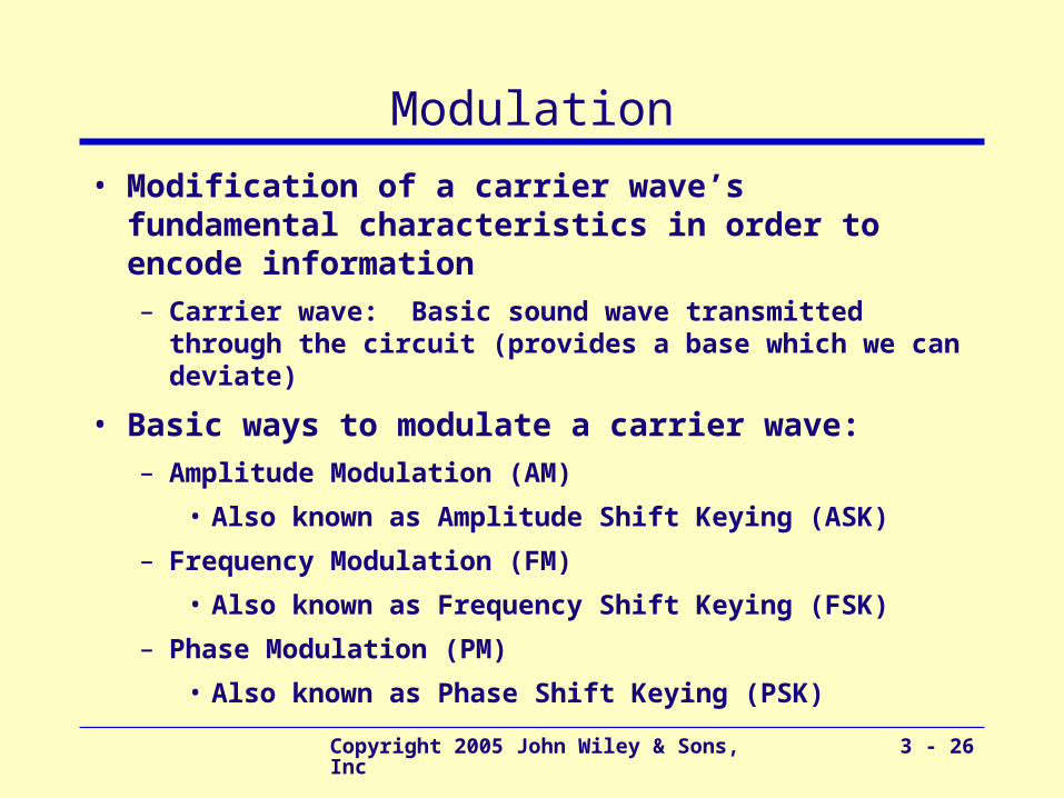
Modulation
• Μodification of a carrier wave’s fundamental characteristics in order to encode information– Carrier wave: Basic sound wave transmitted through
the circuit (provides a base which we can deviate)
• Βasic ways to modulate a carrier wave:– Amplitude Modulation (AM)
• Also known as Amplitude Shift Keying (ASK)
– Frequency Modulation (FM)
• Also known as Frequency Shift Keying (FSK)
– Phase Modulation (PM)
• Also known as Phase Shift Keying (PSK)
Copyright 2005 John Wiley & Sons, Inc 3 - 27
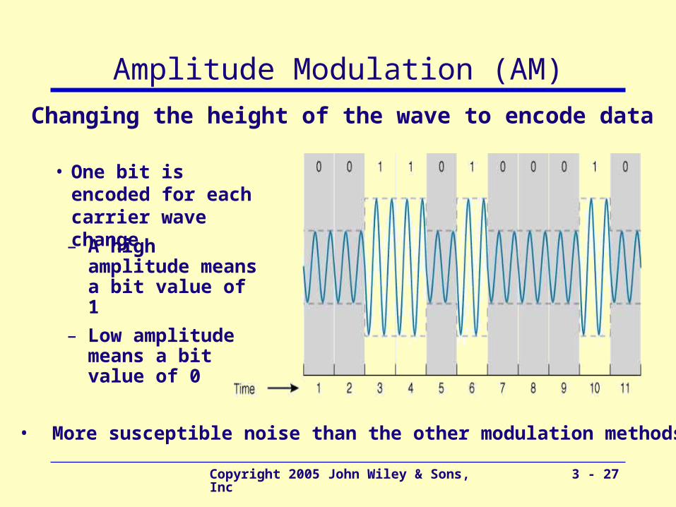
Amplitude Modulation (AM)• Changing the height of the wave to encode data
• One bit is encoded for each carrier wave change
– A high amplitude means a bit value of 1
– Low amplitude means a bit value of 0
• More susceptible noise than the other modulation methods
Copyright 2005 John Wiley & Sons, Inc 3 - 28
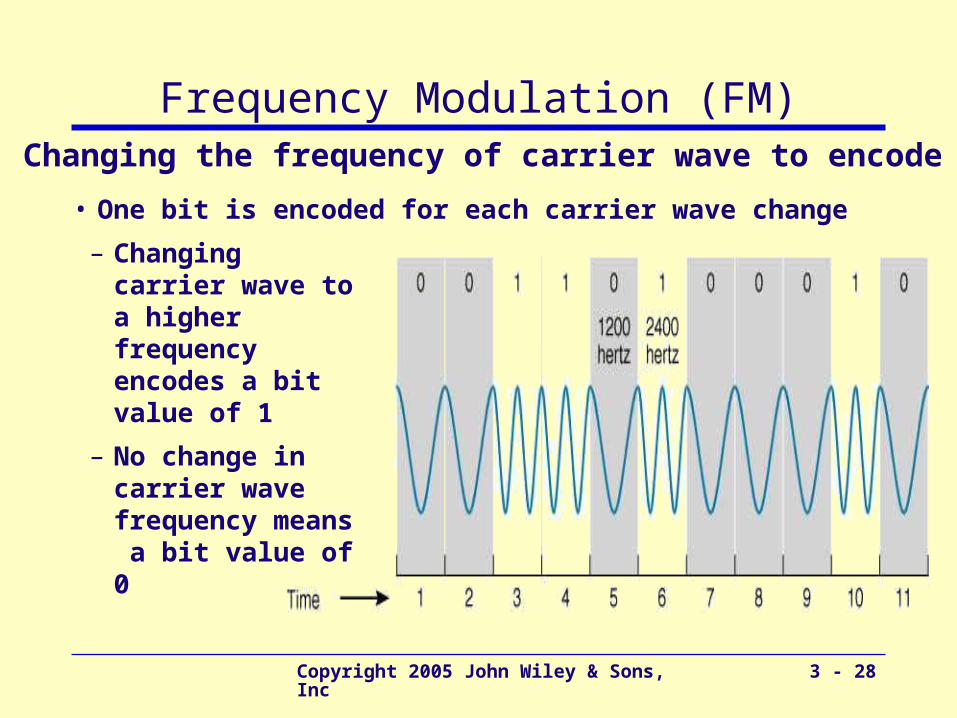
Frequency Modulation (FM)• Changing the frequency of carrier wave to encode data
• One bit is encoded for each carrier wave change
– Changing carrier wave to a higher frequency encodes a bit value of 1
– No change in carrier wave frequency means a bit value of 0
Copyright 2005 John Wiley & Sons, Inc 3 - 29
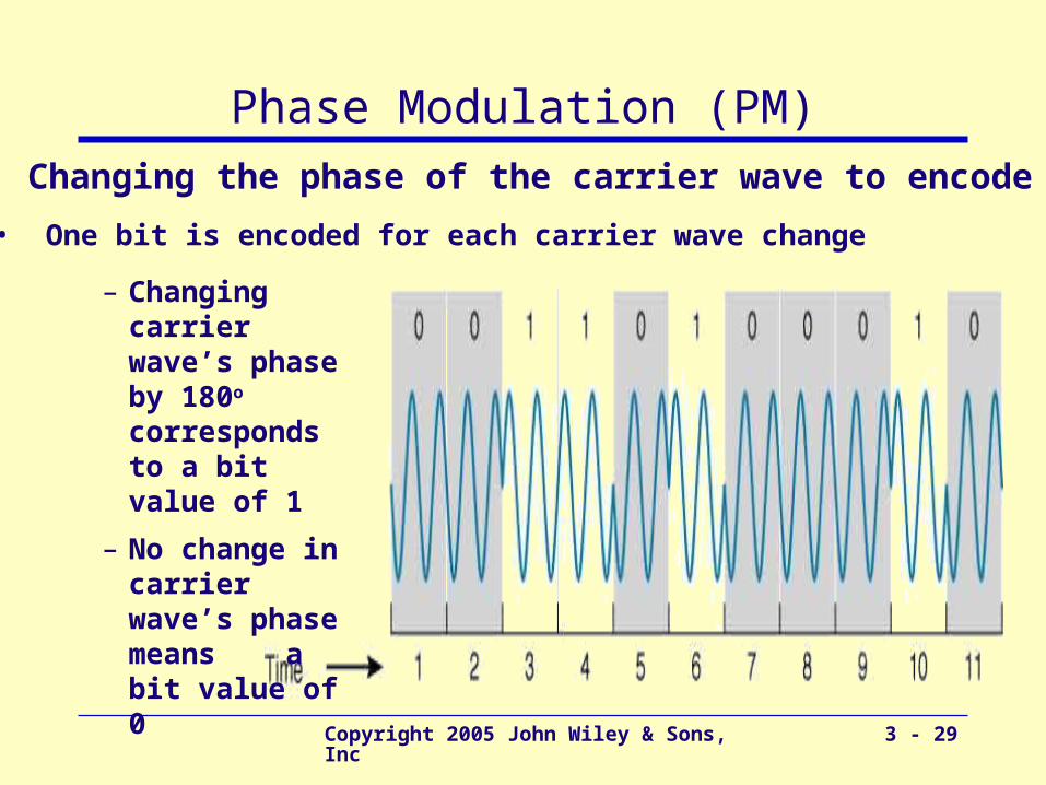
Phase Modulation (PM)• Changing the phase of the carrier wave to encode data
• One bit is encoded for each carrier wave change
– Changing carrier wave’s phase by 180o corresponds to a bit value of 1
– No change in carrier wave’s phase means a bit value of 0
Copyright 2005 John Wiley & Sons, Inc 3 - 30
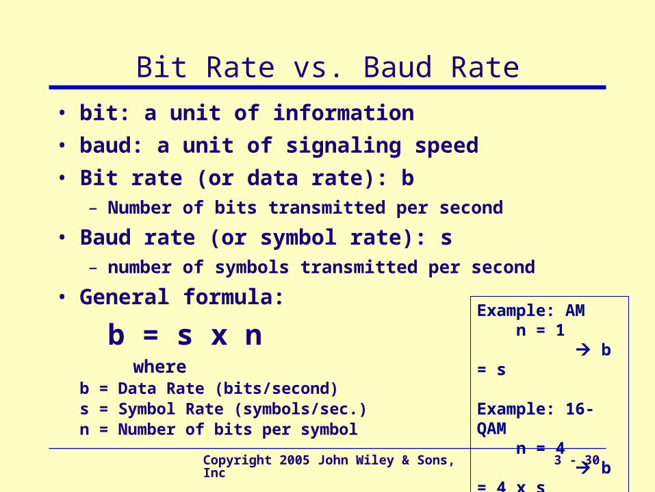
Bit Rate vs. Baud Rate
• bit: a unit of information
• baud: a unit of signaling speed
• Bit rate (or data rate): b– Number of bits transmitted per second
• Baud rate (or symbol rate): s – number of symbols transmitted per second
• General formula:
b = s x n where
b = Data Rate (bits/second)s = Symbol Rate (symbols/sec.)n = Number of bits per symbol
Example: AM n = 1 b = s
Example: 16-QAM n = 4 b = 4 x s
Copyright 2005 John Wiley & Sons, Inc 3 - 31
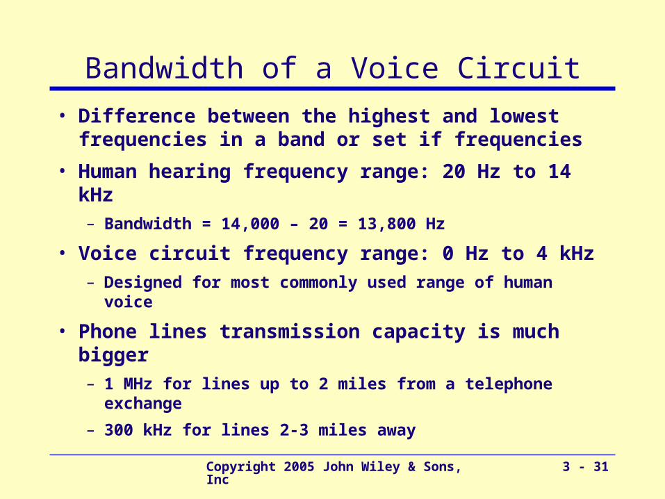
Bandwidth of a Voice Circuit
• Difference between the highest and lowest frequencies in a band or set if frequencies
• Human hearing frequency range: 20 Hz to 14 kHz– Bandwidth = 14,000 – 20 = 13,800 Hz
• Voice circuit frequency range: 0 Hz to 4 kHz– Designed for most commonly used range of human
voice
• Phone lines transmission capacity is much bigger– 1 MHz for lines up to 2 miles from a telephone exchange
– 300 kHz for lines 2-3 miles away
Copyright 2005 John Wiley & Sons, Inc 3 - 32
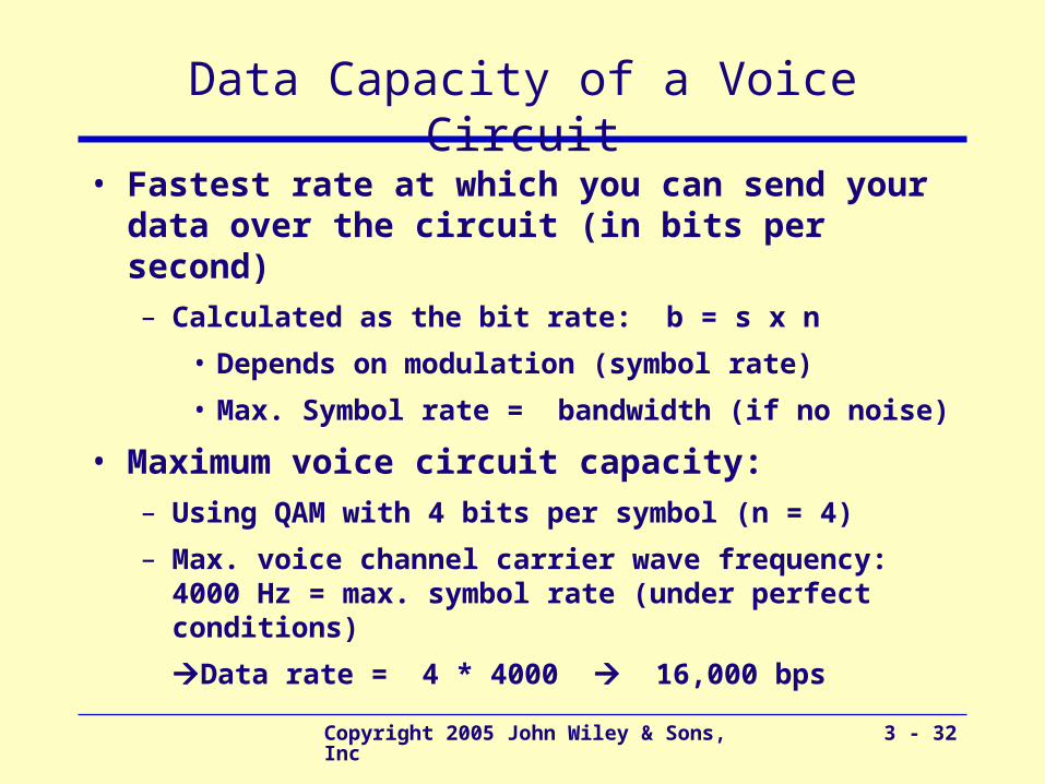
Data Capacity of a Voice Circuit
• Fastest rate at which you can send your data over the circuit (in bits per second)– Calculated as the bit rate: b = s x n
• Depends on modulation (symbol rate)
• Max. Symbol rate = bandwidth (if no noise)
• Maximum voice circuit capacity:– Using QAM with 4 bits per symbol (n = 4)
– Max. voice channel carrier wave frequency: 4000 Hz = max. symbol rate (under perfect conditions)
Data rate = 4 * 4000 16,000 bps
Copyright 2005 John Wiley & Sons, Inc 3 - 33
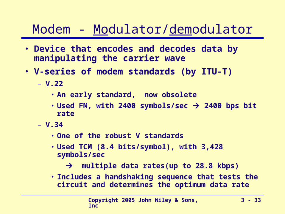
Modem - Modulator/demodulator
• Device that encodes and decodes data by manipulating the carrier wave
• V-series of modem standards (by ITU-T)– V.22
• An early standard, now obsolete
• Used FM, with 2400 symbols/sec 2400 bps bit rate
– V.34
• One of the robust V standards
• Used TCM (8.4 bits/symbol), with 3,428 symbols/sec
multiple data rates(up to 28.8 kbps)
• Includes a handshaking sequence that tests the circuit and determines the optimum data rate
Copyright 2005 John Wiley & Sons, Inc 3 - 34
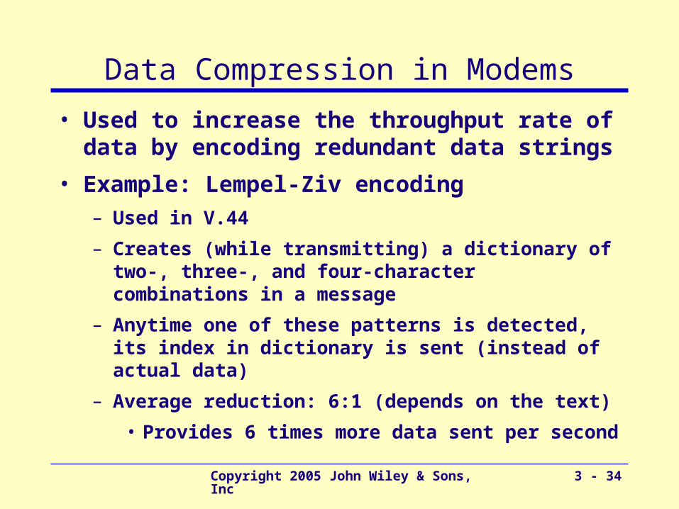
Data Compression in Modems
• Used to increase the throughput rate of data by encoding redundant data strings
• Example: Lempel-Ziv encoding– Used in V.44
– Creates (while transmitting) a dictionary of two-, three-, and four-character combinations in a message
– Anytime one of these patterns is detected, its index in dictionary is sent (instead of actual data)
– Average reduction: 6:1 (depends on the text)
• Provides 6 times more data sent per second
Copyright 2005 John Wiley & Sons, Inc 3 - 35
Digital Transmission of Analog Data
• Analog voice data sent over digital network using digital transmission
• Requires a pair of special devices called Codec - Coder/decoder
– A device that converts an analog voice signal into digital form
• Also converts it back to analog data at the receiving end
– Used by the phone system
Copyright 2005 John Wiley & Sons, Inc 3 - 36
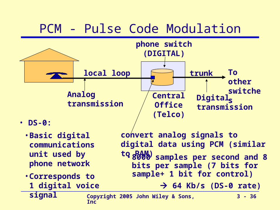
PCM - Pulse Code Modulation
local loop
phone switch(DIGITAL)
Central Office(Telco)
Analog transmission
To other switches
trunk
Digital transmission
convert analog signals to digital data using PCM (similar to PAM)
• 8000 samples per second and 8 bits per sample (7 bits for sample+ 1 bit for control)
64 Kb/s (DS-0 rate)
• DS-0:
• Basic digital communications unit used by phone network
• Corresponds to 1 digital voice signal
Copyright 2005 John Wiley & Sons, Inc 3 - 37
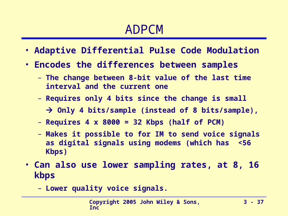
ADPCM
• Adaptive Differential Pulse Code Modulation
• Encodes the differences between samples– The change between 8-bit value of the last time interval
and the current one
– Requires only 4 bits since the change is small
Only 4 bits/sample (instead of 8 bits/sample),
– Requires 4 x 8000 = 32 Kbps (half of PCM)
– Makes it possible to for IM to send voice signals as digital signals using modems (which has <56 Kbps)
• Can also use lower sampling rates, at 8, 16 kbps– Lower quality voice signals.
Copyright 2005 John Wiley & Sons, Inc 3 - 38
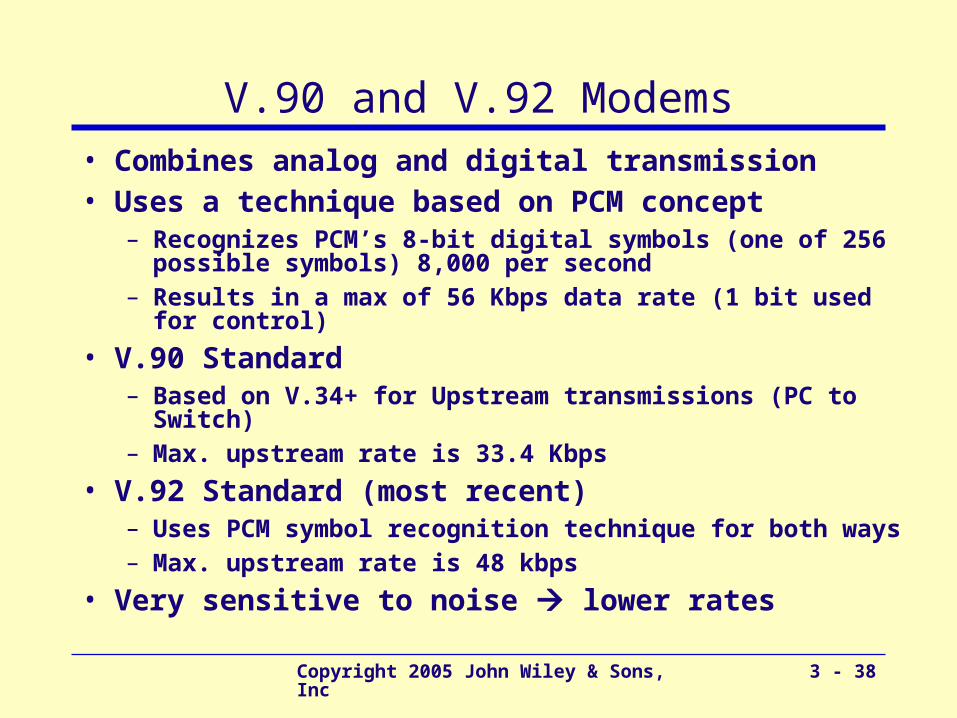
V.90 and V.92 Modems• Combines analog and digital transmission• Uses a technique based on PCM concept
– Recognizes PCM’s 8-bit digital symbols (one of 256 possible symbols) 8,000 per second
– Results in a max of 56 Kbps data rate (1 bit used for control)
• V.90 Standard– Based on V.34+ for Upstream transmissions (PC to Switch)– Max. upstream rate is 33.4 Kbps
• V.92 Standard (most recent)– Uses PCM symbol recognition technique for both ways– Max. upstream rate is 48 kbps
• Very sensitive to noise lower rates
Copyright 2005 John Wiley & Sons, Inc 3 - 39
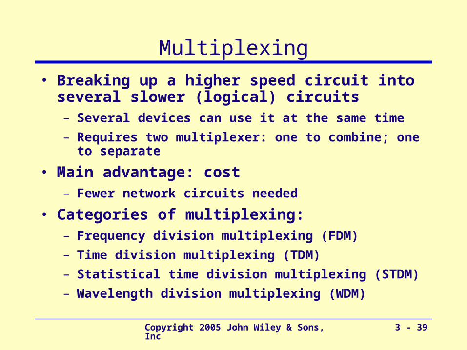
Multiplexing
• Breaking up a higher speed circuit into several slower (logical) circuits– Several devices can use it at the same time
– Requires two multiplexer: one to combine; one to separate
• Main advantage: cost– Fewer network circuits needed
• Categories of multiplexing:– Frequency division multiplexing (FDM)
– Time division multiplexing (TDM)
– Statistical time division multiplexing (STDM)
– Wavelength division multiplexing (WDM)
Copyright 2005 John Wiley & Sons, Inc 3 - 40
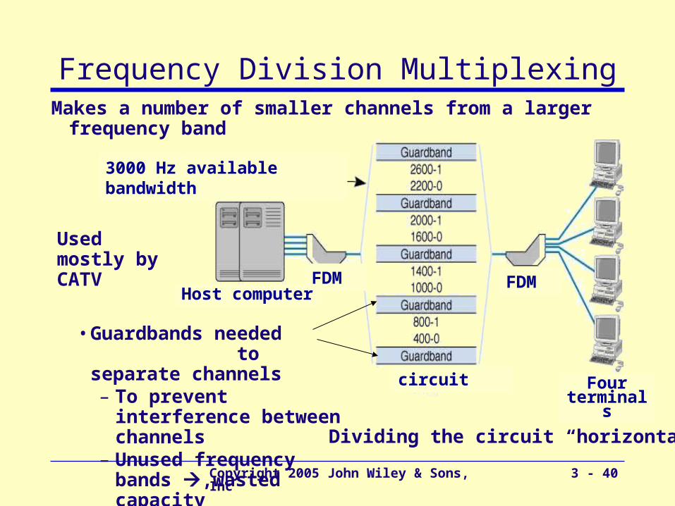
Frequency Division Multiplexing
Dividing the circuit “horizontally
Makes a number of smaller channels from a larger frequency band
• Guardbands needed to separate channels– To prevent interference
between channels– Unused frequency bands
,wasted capacity
Used mostly by CATV
3000 Hz available bandwidth
circuit
FDMFDM
Four terminals
Host computer
Copyright 2005 John Wiley & Sons, Inc 3 - 41
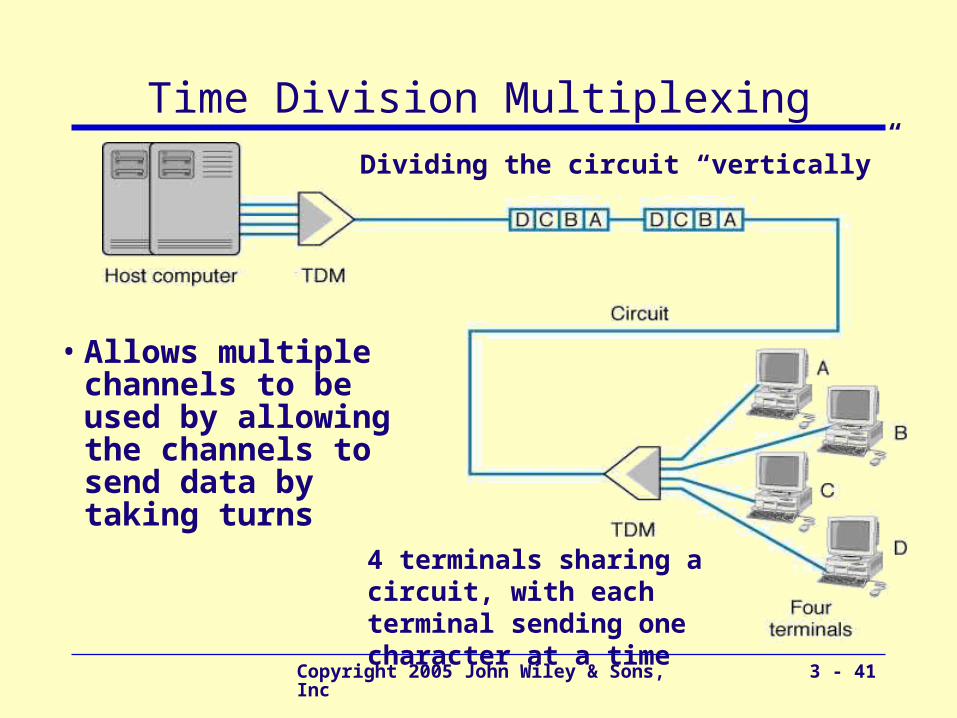
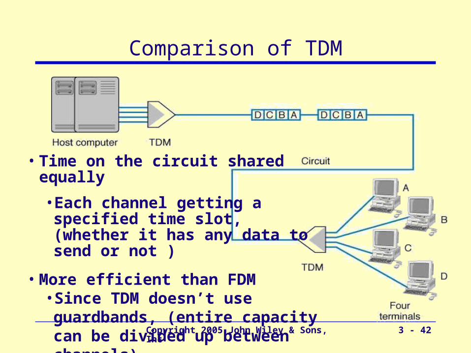
Time Division MultiplexingDividing the circuit “vertically”
• Allows multiple channels to be used by allowing the channels to send data by taking turns
4 terminals sharing a circuit, with each terminal sending one character at a time
Copyright 2005 John Wiley & Sons, Inc 3 - 42
Comparison of TDM
• Time on the circuit shared equally
• Each channel getting a specified time slot, (whether it has any data to send or not )
• More efficient than FDM• Since TDM doesn’t use guardbands, (entire capacity can be divided up between channels)
Copyright 2005 John Wiley & Sons, Inc 3 - 43
Statistical TDM (STDM)
• Designed to make use of the idle time slots– (In TDM, when terminals are not using the multiplexed
circuit, timeslots for those terminals are idle.)
• Uses non-dedicated time slots– Time slots used as needed by the different terminals
• Complexities of STDM– Additional addressing information needed
• Since source of a data sample is not identified by the time slot it occupies
– Potential response time delays (when all terminals try to use the multiplexed circuit intensively)
• Requires memory to store data (in case more data come in than its outgoing circuit capacity can handle)
Copyright 2005 John Wiley & Sons, Inc 3 - 44
Digital Subscriber Line (DSL)
• Became popular as a way to increase data rates in the local loop.– Uses full physical capacity of twisted pair (copper)
phone lines (up to 1 MHz)
• Instead of using the 0-4000 KHz voice channel
• 1 MHz capacity split into (FDM): • a 4 KHz voice channel
• an upstream channel
• a downstream channel
• Requires a pair of DSL modems– One at the customer’s site; one at the CO site
May be divided further (via TDM) to have one or more logical channels

Copyright 2005 John Wiley & Sons, Inc 3 - 45
Data Link Layer - Introduction
• Responsible for moving messages from one device to another
• Controls the way messages are sent on media
• Organizes physical layer bit streams into coherent messages for the network layer
• Major functions of a data link layer protocol– Media Access Control
• Controlling when computers transmit– Error Control
• Detecting and correcting transmission errors– Message Delineation
• Identifying the beginning and end of a message
Data Link Layer
Physical Layer
Network Layer
Copyright 2005 John Wiley & Sons, Inc 3 - 46
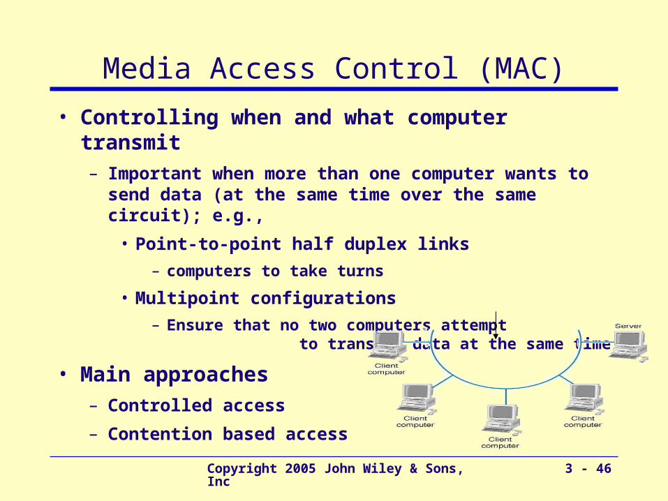
Media Access Control (MAC)
• Controlling when and what computer transmit– Important when more than one computer wants to send
data (at the same time over the same circuit); e.g.,
• Point-to-point half duplex links
– computers to take turns
• Multipoint configurations
– Ensure that no two computers attempt to transmit data at the same time
• Main approaches– Controlled access
– Contention based access
Copyright 2005 John Wiley & Sons, Inc 3 - 47
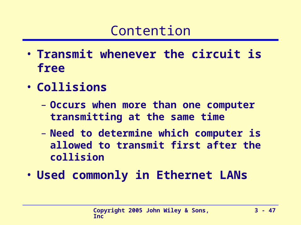
Contention
• Transmit whenever the circuit is free
• Collisions
– Occurs when more than one computer transmitting at the same time
– Need to determine which computer is allowed to transmit first after the collision
• Used commonly in Ethernet LANs
Copyright 2005 John Wiley & Sons, Inc 3 - 48
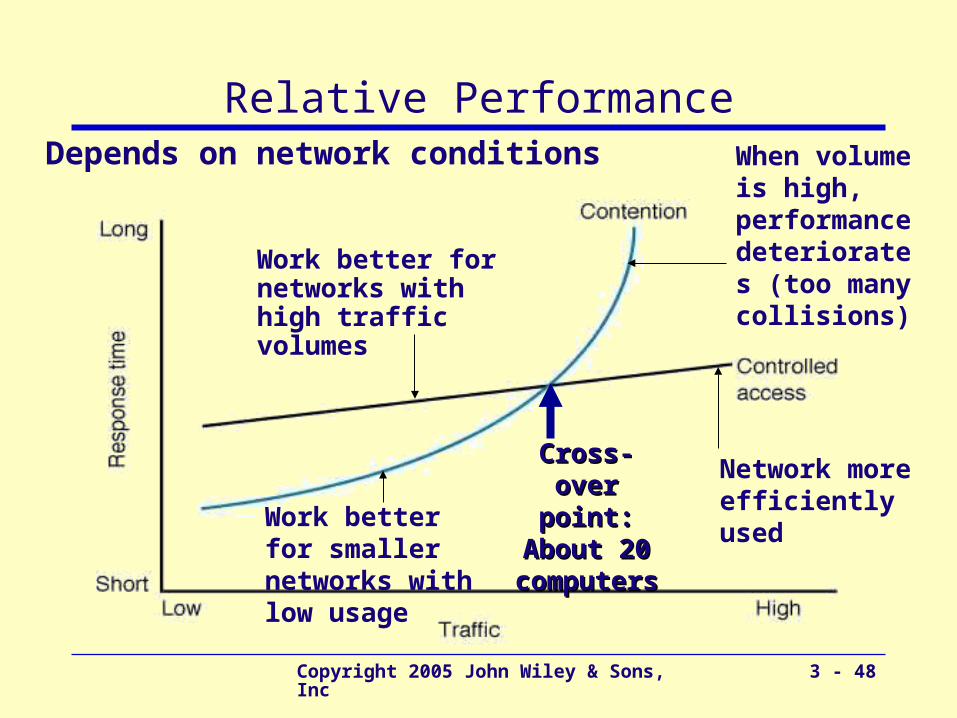
Relative PerformanceDepends on network conditions
Work better for smaller networks with low usage
Work better for networks with high traffic volumes
When volume is high, performance deteriorates (too many collisions)
Network more efficiently used
Cross-over Cross-over point: point:
About 20 About 20 computerscomputers
Copyright 2005 John Wiley & Sons, Inc 3 - 49
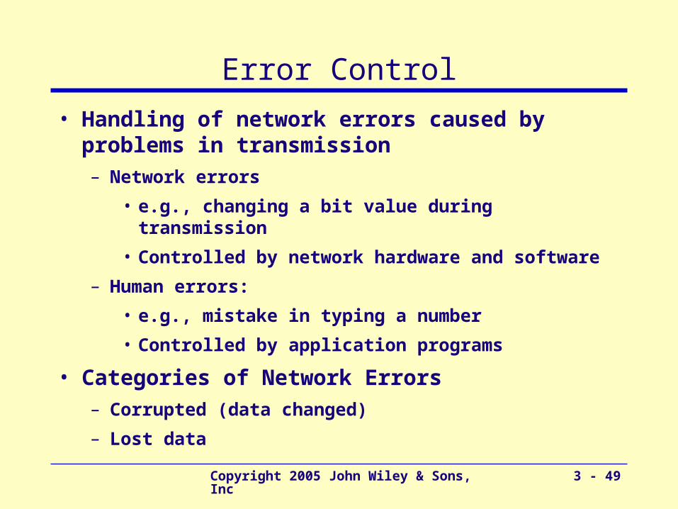
Error Control
• Handling of network errors caused by problems in transmission– Network errors
• e.g., changing a bit value during transmission
• Controlled by network hardware and software
– Human errors:
• e.g., mistake in typing a number
• Controlled by application programs
• Categories of Network Errors– Corrupted (data changed)
– Lost data
Copyright 2005 John Wiley & Sons, Inc 3 - 50
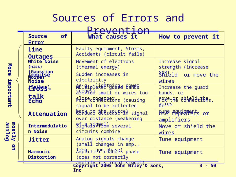
Source of Error What causes it How to prevent it
Line Outages
Faulty equipment, Storms, Accidents (circuit fails)
White Noise (hiss)
(Gaussian Noise)Movement of electrons (thermal energy)
Increase signal strength (increase SNR)
Impulse Noise (Spikes)
Sudden increases in electricity (e.g., lightning, power surges)
Shield or move the wires
Cross-talk Multiplexer guard bands are too small or wires too close together
Increase the guard bands, ormove or shield the wires
Echo
Poor connections (causing signal to be reflected back to the source)
Fix the connections, ortune equipment
Attenuation
Gradual decrease in signal over distance (weakening of a signal)
Use repeaters or amplifiers
Intermodulation Noise
Signals from several circuits combine
Move or shield the wires
Jitter
Analog signals change (small changes in amp., freq., and phase)
Tune equipment
Harmonic Distortion
Amplifier changes phase (does not correctly amplify its input signal)
Tune equipment
Sources of Errors and Prevention
mo
stly on
analo
gM
ore im
po
rtant
Copyright 2005 John Wiley & Sons, Inc 3 - 51
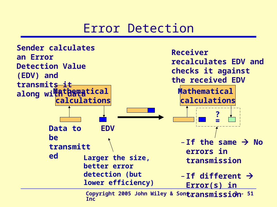
Error Detection
Mathematical calculations
?=
Mathematical calculations
Data to be transmitted
Sender calculates an Error Detection Value (EDV) and transmits it along with data
Receiver recalculates EDV and checks it against the received EDV
– If the same No errors in transmission
– If different Error(s) in transmission
EDV
Larger the size, better error detection (but lower efficiency)
Copyright 2005 John Wiley & Sons, Inc 3 - 52
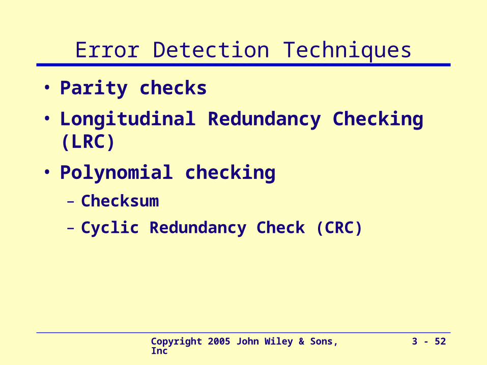
Error Detection Techniques
• Parity checks
• Longitudinal Redundancy Checking (LRC)
• Polynomial checking
– Checksum
– Cyclic Redundancy Check (CRC)
Copyright 2005 John Wiley & Sons, Inc 3 - 53
Parity Checking
• One of the oldest and simplest
• A single bit added to each character– Even parity: number of 1’s remains even
– Odd parity: number of 1’s remains odd
• Receiving end recalculates parity bit– If one bit has been transmitted in error the received
parity bit will differ from the recalculated one
• Simple, but doesn’t catch all errors – If two (or an even number of) bits have been transmitted
in error at the same time, the parity check appears to be correct
– Detects about 50% of errors

Copyright 2005 John Wiley & Sons, Inc 3 - 54
LRC - Longitudinal Redundancy Checking
• Adds an additional character (instead of a bit)– Block Check Character (BCC) to each block of data
– Determined like parity but, but counting longitudinally through the message (as well as vertically)
– Calculations are based on the 1st bit, 2nd bit, etc. (of all characters) in the block
• 1st bit of BCC number of 1’s in the 1st bit of characters
• 2nd bit of BCC number of 1’s in the 2ndt bit of characters
• Major improvement over parity checking– 98% error detection rate for burst errors ( > 10 bits)
– Less capable of detecting single bit errors
Copyright 2005 John Wiley & Sons, Inc 3 - 55
Polynomial Checking
• Adds 1 or more characters to the end of message (based on a mathematical algorithm)
• Two types: Checksum and CRC
• Checksum– Calculated by adding decimal values of each character
in the message,
– Dividing the total by 255. and
– Saving the remainder (1 byte value) and using it as the checksum
– 95% effective
• Cyclic Redundancy Check (CRC)– Computed by calculating the remainder to a division
problem:
Copyright 2005 John Wiley & Sons, Inc 3 - 56
Error Correction
• Once detected, the error must be corrected
• Error correction techniques– Retransmission (a.k.a, Backward error correction)
• Simplest, most effective, least expensive, most commonly used
• Corrected by retransmission of the data
– Receiver, when detecting an error, asks the sender to retransmit the message
• Often called Automatic Repeat Request (ARQ)
– Forward Error Correction
• Receiving device can correct incoming messages itself

Copyright 2005 John Wiley & Sons, Inc 3 - 57
Automatic Repeat Request (ARQ)
• Process of requesting that a data transmission be resent
• Main ARQ protocols– Stop and Wait ARQ (A half duplex technique)
• Sender sends a message and waits for acknowledgment, then sends the next message
• Receiver receives the message and sends an acknowledgement, then waits for the next message
– Continuous ARQ (A full duplex technique)
• Sender continues sending packets without waiting for the receiver to acknowledge
• Receiver continues receiving messages without acknowledging them right away
Copyright 2005 John Wiley & Sons, Inc 3 - 58
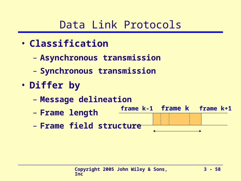
Data Link Protocols
• Classification
– Asynchronous transmission
– Synchronous transmission
• Differ by
– Message delineation
– Frame length
– Frame field structure
frame k frame k+1frame k-1
Copyright 2005 John Wiley & Sons, Inc 3 - 59
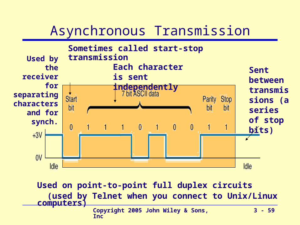
Asynchronous Transmission
Each character is sent independently
Sometimes called start-stop transmission
Sent between transmissions (a series of stop bits)
Used by the receiver for separating characters
and for synch.
Used on point-to-point full duplex circuits (used by Telnet when you connect to Unix/Linux computers)
Copyright 2005 John Wiley & Sons, Inc 3 - 60
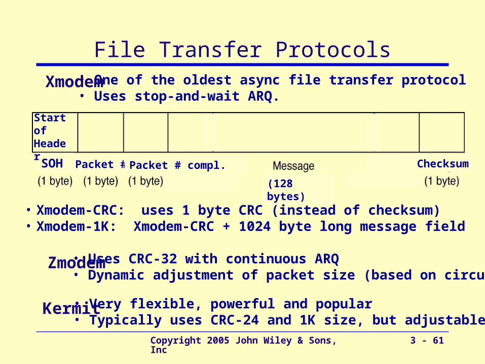
Asynchronous File Transfer
• Used on – Point-to-point asynchronous circuits
– Typically over phone lines via modem
– Computer to computer for transfer of data files
• Characteristics of file transfer protocols– Designed to transmit error-free data
– Group data into blocks to be transmitted (rather sending character by character)
• Popular File transfer Protocols– Xmodem, Zmodem, and Kermit
Copyright 2005 John Wiley & Sons, Inc 3 - 61
File Transfer Protocols
SOH Packet # Packet # compl.
(128 bytes)
Checksum
Start of Header
• One of the oldest async file transfer protocol• Uses stop-and-wait ARQ.
• Xmodem-CRC: uses 1 byte CRC (instead of checksum) • Xmodem-1K: Xmodem-CRC + 1024 byte long message field
Xmodem
Zmodem
Kermit
• Uses CRC-32 with continuous ARQ• Dynamic adjustment of packet size (based on circuit)
• Very flexible, powerful and popular• Typically uses CRC-24 and 1K size, but adjustable
Copyright 2005 John Wiley & Sons, Inc 3 - 62
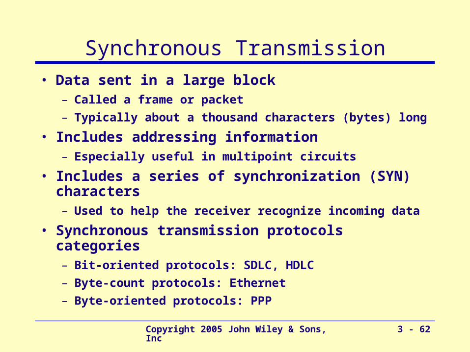
Synchronous Transmission
• Data sent in a large block – Called a frame or packet
– Typically about a thousand characters (bytes) long
• Includes addressing information– Especially useful in multipoint circuits
• Includes a series of synchronization (SYN) characters – Used to help the receiver recognize incoming data
• Synchronous transmission protocols categories– Bit-oriented protocols: SDLC, HDLC
– Byte-count protocols: Ethernet
– Byte-oriented protocols: PPP

Copyright 2005 John Wiley & Sons, Inc 3 - 63
HDLC – High-Level Data Link Control
• Formal standard developed by ISO
• Same as SDLC, except– Longer address and control fields
– Larger sliding window size
– And more
• Basis for many other Data Link Layer protocols– LAP-B (Link Accedes Protocol – Balanced)
• Used by X.25 technology
– LAP-D (Link Accedes Protocol – Balanced)
• Used by ISDN technology
– LAP- F (Used by Frame Relay technology)
Copyright 2005 John Wiley & Sons, Inc 3 - 64
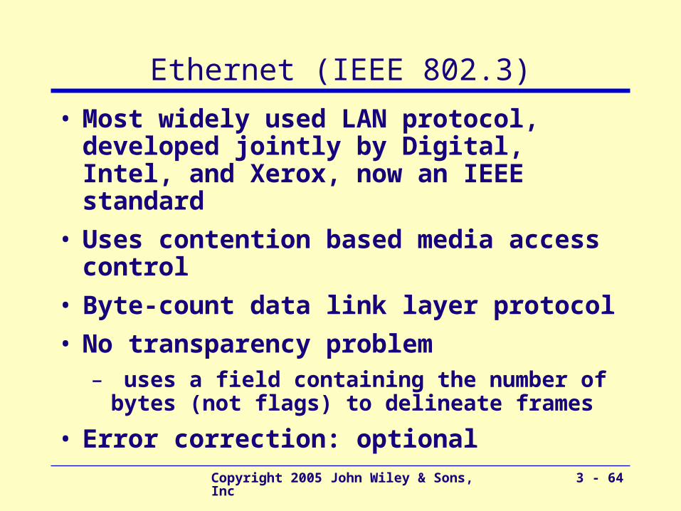
Ethernet (IEEE 802.3)
• Most widely used LAN protocol, developed jointly by Digital, Intel, and Xerox, now an IEEE standard
• Uses contention based media access control
• Byte-count data link layer protocol
• No transparency problem– uses a field containing the number of bytes
(not flags) to delineate frames
• Error correction: optional
Copyright 2005 John Wiley & Sons, Inc 3 - 65
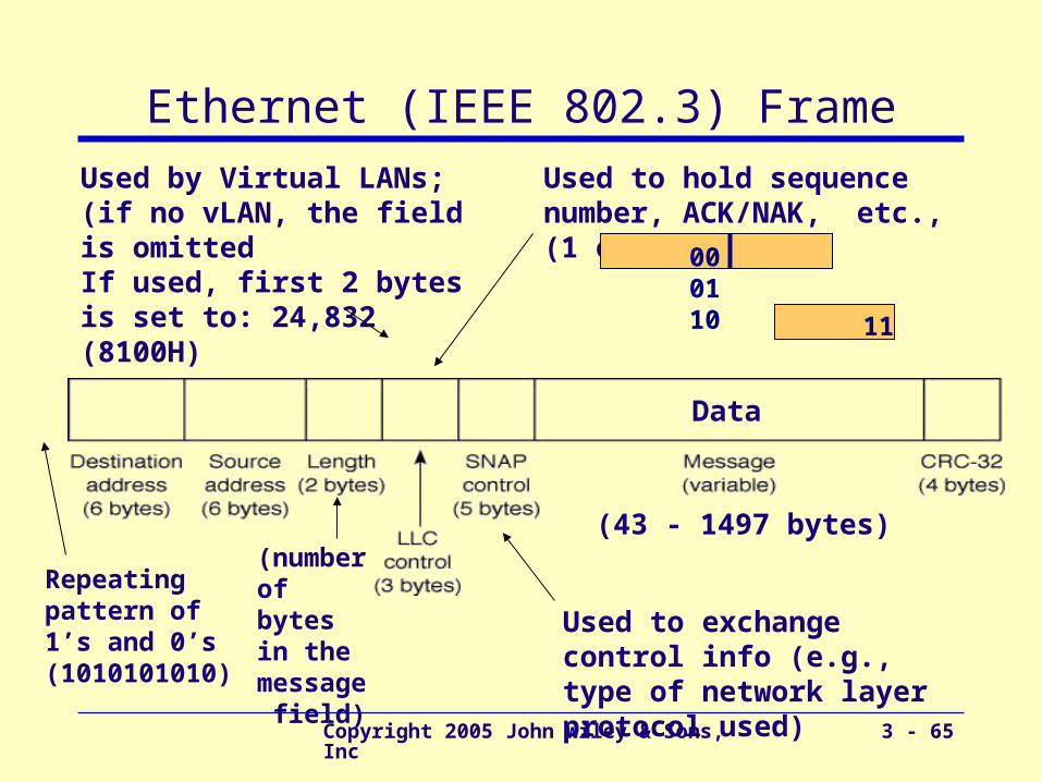
Ethernet (IEEE 802.3) Frame
(number of bytes in the message field)
Data
(43 - 1497 bytes)
Repeating pattern of 1’s and 0’s (1010101010)
Used by Virtual LANs; (if no vLAN, the field is omittedIf used, first 2 bytes is set to: 24,832 (8100H)
Used to exchange control info (e.g., type of network layer protocol used)
Used to hold sequence number, ACK/NAK, etc., (1 or 2 bytes)
000110 11
Copyright 2005 John Wiley & Sons, Inc 3 - 66
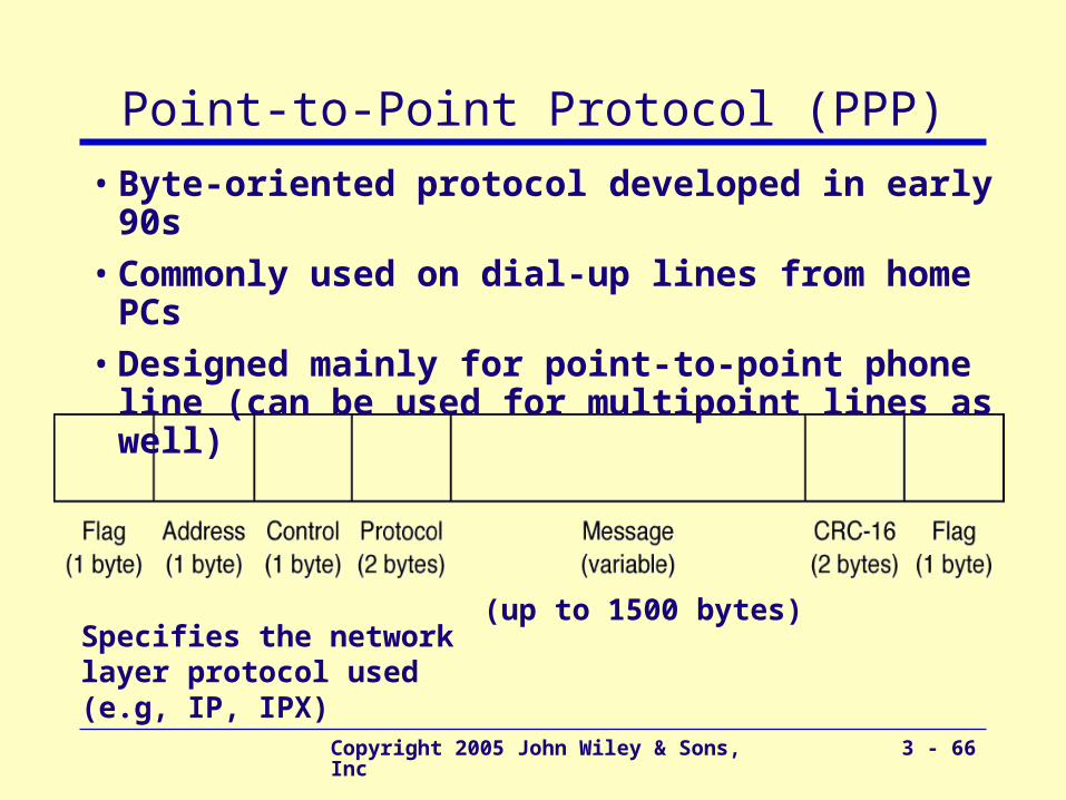
Point-to-Point Protocol (PPP)
• Byte-oriented protocol developed in early 90s
• Commonly used on dial-up lines from home PCs
• Designed mainly for point-to-point phone line (can be used for multipoint lines as well)
(up to 1500 bytes)Specifies the network layer protocol used (e.g, IP, IPX)
Copyright 2005 John Wiley & Sons, Inc 3 - 67
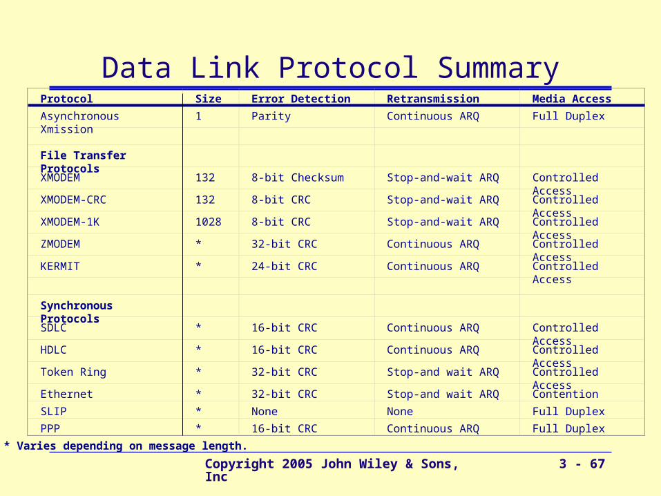
Protocol Size Error Detection Retransmission Media Access
Asynchronous Xmission 1 Parity Continuous ARQ Full Duplex
File Transfer Protocols
XMODEM 132 8-bit Checksum Stop-and-wait ARQ Controlled Access
XMODEM-CRC 132 8-bit CRC Stop-and-wait ARQ Controlled Access
XMODEM-1K 1028 8-bit CRC Stop-and-wait ARQ Controlled Access
ZMODEM * 32-bit CRC Continuous ARQ Controlled Access
KERMIT * 24-bit CRC Continuous ARQ Controlled Access
Synchronous Protocols
SDLC * 16-bit CRC Continuous ARQ Controlled Access
HDLC * 16-bit CRC Continuous ARQ Controlled Access
Token Ring * 32-bit CRC Stop-and wait ARQ Controlled Access
Ethernet * 32-bit CRC Stop-and wait ARQ Contention
SLIP * None None Full Duplex
PPP * 16-bit CRC Continuous ARQ Full Duplex
* Varies depending on message length.
Data Link Protocol Summary
Copyright 2005 John Wiley & Sons, Inc 3 - 68
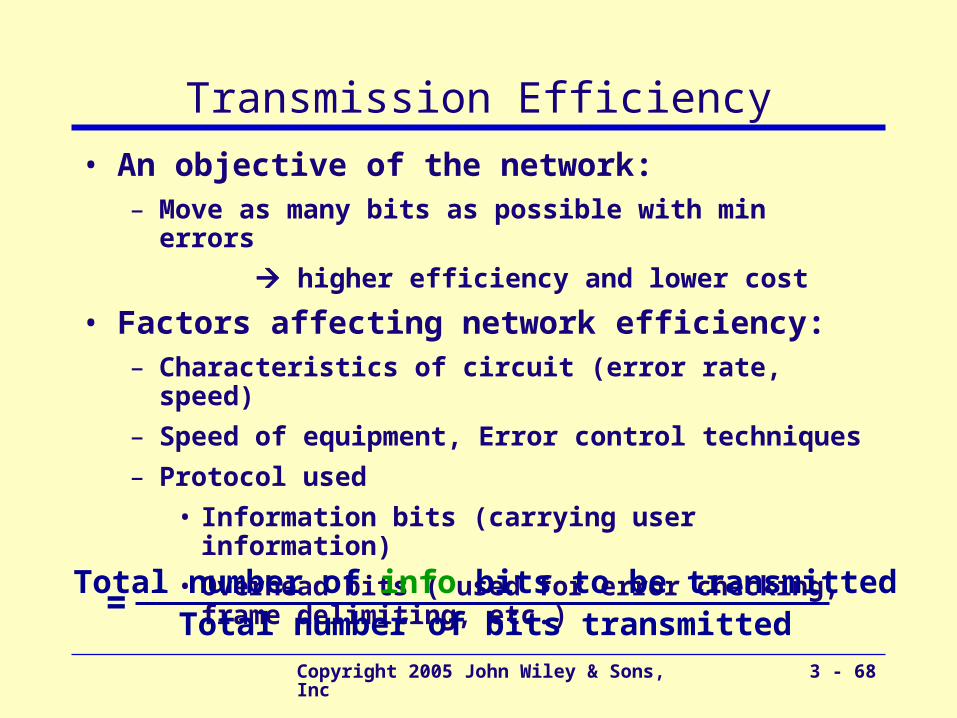
Transmission Efficiency
• An objective of the network:– Move as many bits as possible with min errors
higher efficiency and lower cost
• Factors affecting network efficiency:– Characteristics of circuit (error rate, speed)
– Speed of equipment, Error control techniques
– Protocol used
• Information bits (carrying user information)
• Overhead bits ( used for error checking, frame delimiting, etc.)
Total number of info bits to be transmittedTotal number of bits transmitted
=
Copyright 2005 John Wiley & Sons, Inc 3 - 69
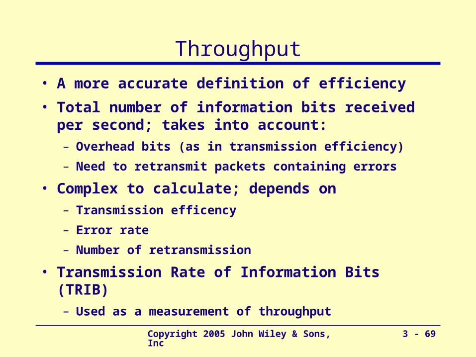
Throughput
• A more accurate definition of efficiency
• Total number of information bits received per second; takes into account:– Overhead bits (as in transmission efficiency)
– Need to retransmit packets containing errors
• Complex to calculate; depends on– Transmission efficency
– Error rate
– Number of retransmission
• Transmission Rate of Information Bits (TRIB)– Used as a measurement of throughput