Embed Size (px)
Citation preview
Copyright -2005-2108 Kenneth M. Chipps Ph.D. www.chipps.com
Cisco CCNA ExplorationCCNA 3
LAN Switching and WirelessChapter 7
Basic Wireless Concepts and ConfigurationLast Update 2010.08.08
110.0
1
Objectives
• Learn the basics about wireless local area networks
Copyright -2005-2108 Kenneth M. Chipps Ph.D. www.chipps.com
2
Why Use Wireless
• A wireless network should never be the first choice for a local area network
• As these networks must operate in an unbounded, constantly changing, unlicensed environment their use is always problematic
• Use them where nothing else will work to solve the problem at hand
Copyright -2005-2108 Kenneth M. Chipps Ph.D. www.chipps.com
3
Business Use of Wireless LANs
• In a business the wireless network should always be viewed as merely an extension of the wired network
• It is an onramp to the wired network
Copyright -2005-2108 Kenneth M. Chipps Ph.D. www.chipps.com
4
Nature of Wireless Networks
• It must be kept in mind that wireless networks are fundamentally different from those that use wires
• Wireless signals are unbounded and dynamic
• A wireless signal’s environment is quite similar to a microclimate as used when discussing the weather
Copyright -2005-2108 Kenneth M. Chipps Ph.D. www.chipps.com
5
Nature of Wireless Networks
• In fact, the weather and wireless networks are very similar
• They both suffer from the same problem• For the weather we know about the
behavior of large weather systems and climate in general
• We can then predict that in the summer the weather will be hot
Copyright -2005-2108 Kenneth M. Chipps Ph.D. www.chipps.com
6
Nature of Wireless Networks
• During the monsoon, it will rain often• What we do not know is exactly where it
will rain and exactly how much• Even if rain can be predicted for an area,
will it rain on my house• This is the microclimate problem• There are simply too many variables,
engaging in too many interactions
Copyright -2005-2108 Kenneth M. Chipps Ph.D. www.chipps.com
7

Nature of Wireless Networks
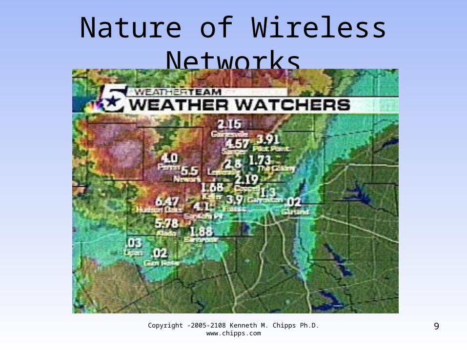
• Let’s look at an example of this problem related to forecasting exactly where it will rain
• The forecast was for a 100 percent chance of rain for the entire area
• But where exactly did it actually rain and how much at each location
Copyright -2005-2108 Kenneth M. Chipps Ph.D. www.chipps.com
8
Nature of Wireless Networks
Copyright -2005-2108 Kenneth M. Chipps Ph.D. www.chipps.com
9
Nature of Wireless Networks
• As the map shows if poured in some places and did not rain at all in others
• We have the same problem with radio frequency networks as we have with the weather network
• Much is known, in general, about how radio frequency signals traverse the environment
Copyright -2005-2108 Kenneth M. Chipps Ph.D. www.chipps.com
10
Nature of Wireless Networks
• But we cannot accurately predict what they will do or not do from a base station antenna to an end user’s site a few kilometers away
• The usual way of handling this problem for both the weather and radio frequency networks is a fudge factor or fade margin
Copyright -2005-2108 Kenneth M. Chipps Ph.D. www.chipps.com
11
Wireless LAN Standards
• Here are the current standards that define a complete wireless network– 802.11a– 802.11b– 802.11g– 802.11n
• Let’s look at each one
Copyright -2005-2108 Kenneth M. Chipps Ph.D. www.chipps.com
12
802.11a
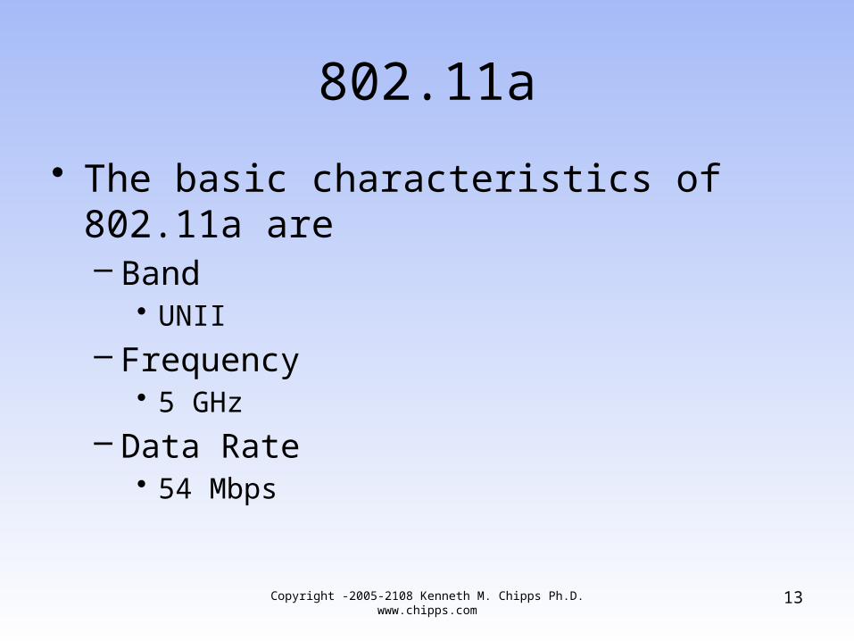
• The basic characteristics of 802.11a are– Band
• UNII
– Frequency• 5 GHz
– Data Rate• 54 Mbps
13Copyright -2005-2108 Kenneth M. Chipps Ph.D. www.chipps.com
802.11a
• 802.11a is meant to be a high speed alternative to 802.11b, operating in the less congested 5 GHz frequency range
14Copyright -2005-2108 Kenneth M. Chipps Ph.D. www.chipps.com
802.11b
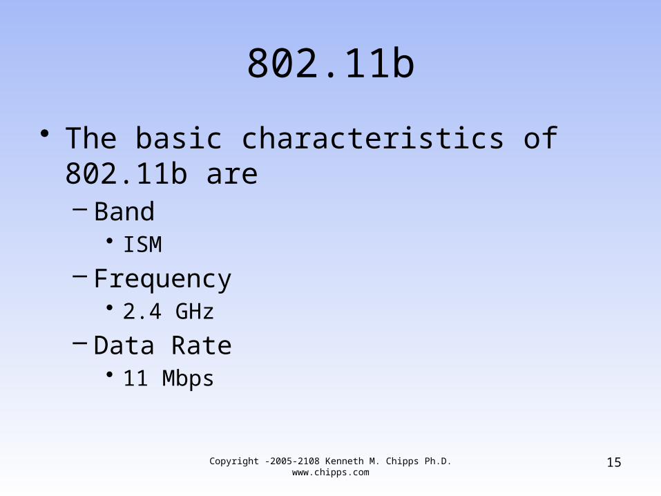
• The basic characteristics of 802.11b are– Band
• ISM
– Frequency• 2.4 GHz
– Data Rate• 11 Mbps
15Copyright -2005-2108 Kenneth M. Chipps Ph.D. www.chipps.com
802.11b
• 802.11b is the most widely used standard for wireless local area networks
• It sees some use in campus area networks as a way to bridge between locations, and as a way to connect to the local area network from anywhere on the campus
• 802.11b is currently used to deliver Internet access in metropolitan area networks
16Copyright -2005-2108 Kenneth M. Chipps Ph.D. www.chipps.com
802.11g
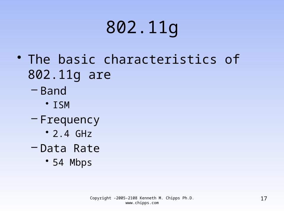
• The basic characteristics of 802.11g are– Band
• ISM
– Frequency• 2.4 GHz
– Data Rate• 54 Mbps
17Copyright -2005-2108 Kenneth M. Chipps Ph.D. www.chipps.com
802.11g
• Approved on 12 June 2003, 802.11g is in the 2.4 GHz band
• It is designed to be a higher bandwidth - 54Mbs - successor to the popular 802.11b standard
• It also specifies three available radio channels
18Copyright -2005-2108 Kenneth M. Chipps Ph.D. www.chipps.com
802.11n
• 802.11n provides higher speeds and greater coverage area than 802.11a/b/g
• How does 802.11n do this
19Copyright -2005-2108 Kenneth M. Chipps Ph.D. www.chipps.com
Engineering Improvements
• It has always been true that regardless of the advertised maximum theoretical data rate the real number for throughout was always about 50 percent of the maximum theoretical data rate
• With 802.11n this percentage is around 75 percent
• This was accomplished by making several small changes to the way the stream of bits is transmitted
20Copyright -2005-2108 Kenneth M. Chipps Ph.D. www.chipps.com
Engineering Improvements
• These basic improvements are enough to raise the theoretical data rate to about 75 Mbps
• In practice this is 54 Mbps rather than the 38 Mbps that would have been true before
21Copyright -2005-2108 Kenneth M. Chipps Ph.D. www.chipps.com
Engineering Improvements
• Let’s look at these changes in more detail– Optimized preamble– Reduced guard interval between symbols– Shorter interframe gap– One ACK for multiple frames– Better error correction– Use of OFDM– Narrower guard bands
22Copyright -2005-2108 Kenneth M. Chipps Ph.D. www.chipps.com
Engineering Improvements
• The use of these improvements assumes an all 802.11n environment
• Introduce 802.11a/b/g equipment and the data rates drop
23Copyright -2005-2108 Kenneth M. Chipps Ph.D. www.chipps.com
Channel Bonding
• The second method used to increase data transfer rates even higher is channel bonding
• This takes one or more 20 MHz channels and turns them into a 40 MHz channel
• This raises the theoretical rate to 150 Mbps
• The practical rate is about 105 Mbps
24Copyright -2005-2108 Kenneth M. Chipps Ph.D. www.chipps.com
Channel Bonding
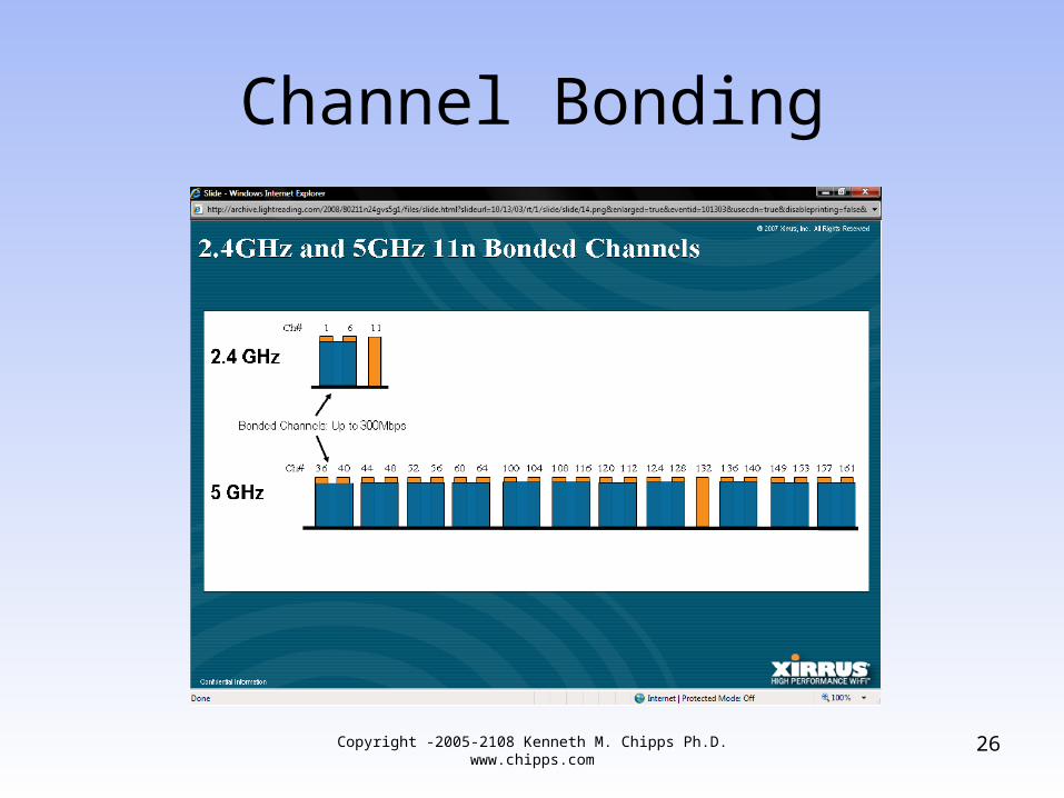
• Of course channel bonding is useless in the 2.4 GHz band with only three available channels
• 5 GHz must be deployed• As above the introduction of 802.11a/b/g
equipment slows this rate improvement
Copyright -2005-2108 Kenneth M. Chipps Ph.D. www.chipps.com
25
Channel Bonding
Copyright -2005-2108 Kenneth M. Chipps Ph.D. www.chipps.com
26
MIMO
• The last major enhancement is the use of MIMO
• MIMO allows multiple streams of data over the same frequency
• This requires separate antennas on both devices, the access point and the NIC
• Up to four radios and their antennas can be used
27Copyright -2005-2108 Kenneth M. Chipps Ph.D. www.chipps.com
MIMO
• This is expressed as a number such as– 2X2
• This being two radios and two antennas
– If diversity is present then the expression is something like 2X3
– Where there are still two radios with an antenna each, as well as a diversity antenna
28Copyright -2005-2108 Kenneth M. Chipps Ph.D. www.chipps.com
MIMO
– MIMO is where the large theoretical streams come from
– In other words 150 Mbps goes to 300 in a 2X2 configuration
Copyright -2005-2108 Kenneth M. Chipps Ph.D. www.chipps.com
29
Spatial Multiplexing
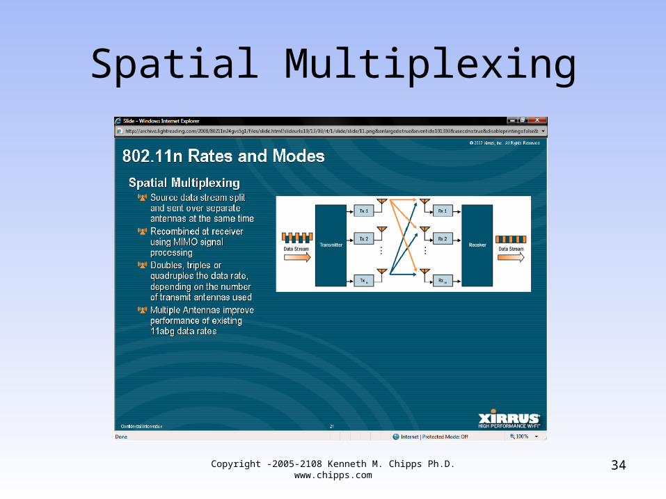
• MIMO introduces the idea of spatial multiplexing where separate data streams are feed to the same device
• Two streams means double the rate• Three streams triple the rate and so on• The weird thing about this is spatial
multiplexing requires bad signals in the form of multipath
30Copyright -2005-2108 Kenneth M. Chipps Ph.D. www.chipps.com
Spatial Multiplexing
• Where before multipath was a problem• Now we need it• As multipath cannot be setup, it just
happens, the likelihood of consistent spatial multiplexing is low
• Now we need not line of sight, but near line of sight
• Reflections are needed to make this work
31Copyright -2005-2108 Kenneth M. Chipps Ph.D. www.chipps.com
Spatial Multiplexing
• So instead of placing the access point in the middle of the service area, place it off to the side in the next room for example
• 100 percent coverage of an area with multiple streams will not be possible
• Some will receive them and some will not
32Copyright -2005-2108 Kenneth M. Chipps Ph.D. www.chipps.com
Spatial Multiplexing
• Who will is impossible to predict• Furthermore, all of this assumes that the
NICs will have a set of antennas as well• Each antenna must be separated from the
other• This will be difficult in must PCMCIA cards
and many laptop computer
Copyright -2005-2108 Kenneth M. Chipps Ph.D. www.chipps.com
33
Spatial Multiplexing
Copyright -2005-2108 Kenneth M. Chipps Ph.D. www.chipps.com
34
Practical Data Rates
• What real world data rates can be expected– 75 Mbps in low noise environment with
sufficient free channels is practical– 150 Mbps is a best case
35Copyright -2005-2108 Kenneth M. Chipps Ph.D. www.chipps.com

802.11n Data Rates
Copyright -2005-2108 Kenneth M. Chipps Ph.D. www.chipps.com
36
The Spread Spectrum Concept
• Spread spectrum is a communication technique that is characterized by wide bandwidth and low peak power
• These signals are noise-like• Therefore they are hard to detect, and
even harder to intercept or demodulate without the correct equipment
Copyright -2005-2108 Kenneth M. Chipps Ph.D. www.chipps.com
37
The Spread Spectrum Concept
• This is why it was originally used by the military
• The main requirement then for a signal to be spread spectrum is that the bandwidth is much wider than is needed to actually send the information
Copyright -2005-2108 Kenneth M. Chipps Ph.D. www.chipps.com
38
The Spread Spectrum Concept
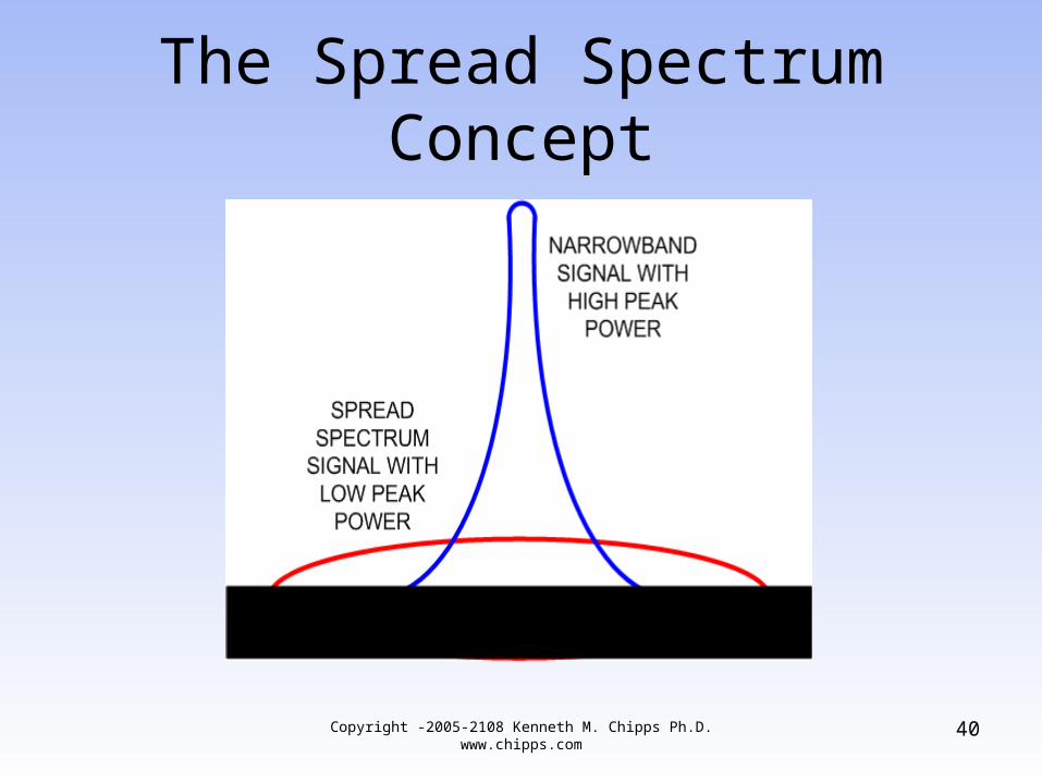
• This is in contrast to the more typical narrowband method that uses a small slice of the spectrum and high peak power
• This higher power is needed to raise the signal above the noise floor
Copyright -2005-2108 Kenneth M. Chipps Ph.D. www.chipps.com
39
The Spread Spectrum Concept
Copyright -2005-2108 Kenneth M. Chipps Ph.D. www.chipps.com
40
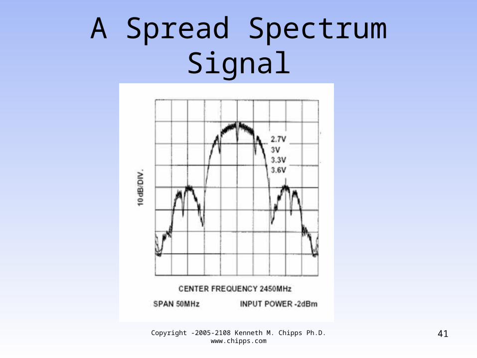
A Spread Spectrum Signal
Copyright -2005-2108 Kenneth M. Chipps Ph.D. www.chipps.com
41
Using Spread Spectrum
• In the United States of America the FCC – Federal Communication Commission limits the specific implementations of spread spectrum technology that may be used in wireless transmissions as do the regulatory bodies in most countries
• For the US these are specified in the Code of Federal Regulations Volume 47, Part 15
Copyright -2005-2108 Kenneth M. Chipps Ph.D. www.chipps.com
42
DSSS
• DSSS uses a bandwidth of 22 MHz in 802.11 standards based systems
• In DSSS the transmitter sends each bit on all channels
• This means DSSS provides redundancy because each individual bit is actually transmitted on more than one narrowband channel
Copyright -2005-2108 Kenneth M. Chipps Ph.D. www.chipps.com
43
DSSS
• More specifically the carrier is modulated by a digital code, with the code rate being larger than the information bit rate
• The code bits represent the redundant bit pattern that is applied to each information bit to be transmitted
• This bit pattern is called the chip or chipping code
Copyright -2005-2108 Kenneth M. Chipps Ph.D. www.chipps.com
44
DSSS
• With this redundancy, there is less possibility of data loss
• The longer the chip, the better is the ability of the receiver to recover the original data
• The direct sequence starts with a carrier signal being modulated with a code sequence
• The number of chips determines how much spreading occurs
Copyright -2005-2108 Kenneth M. Chipps Ph.D. www.chipps.com
45
DSSS
• The number of chips per bit and the speed of the coding, in other words the chips per second, determines the data rate
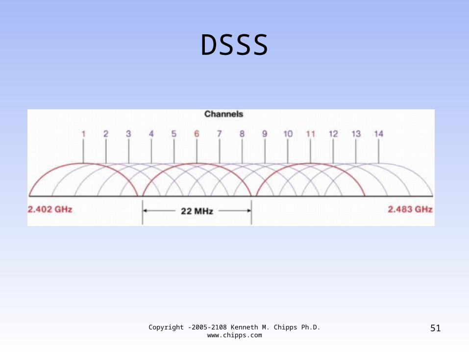
• In a DSSS system a defined set of channels is used
• The 802.11b channels will be used to illustrate this
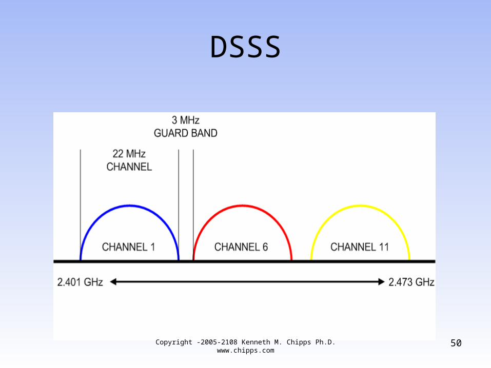
• In 802.11b each channel is 22 MHz wide
Copyright -2005-2108 Kenneth M. Chipps Ph.D. www.chipps.com
46
DSSS
• Channel 1 operates from 2.401 GHz to 2.423 GHz, which is 11 MHz on each side of 2.412 GHz
• One problem with this approach is that using two systems in the same physical space on the same or a nearby channel will result in interference and lower throughput of each system
Copyright -2005-2108 Kenneth M. Chipps Ph.D. www.chipps.com
47
DSSS
• To prevent this in a 802.11b system the equipment should be deployed in the same physical space only if channels at least five channels apart are used
• This is because the center frequencies are 5 MHz apart and the channels are 22 MHz wide
Copyright -2005-2108 Kenneth M. Chipps Ph.D. www.chipps.com
48
DSSS
• This means in a 802.11b system only channels 1, 6, and 11 can be used in the same space
Copyright -2005-2108 Kenneth M. Chipps Ph.D. www.chipps.com
49
DSSS
Copyright -2005-2108 Kenneth M. Chipps Ph.D. www.chipps.com
50
DSSS
Copyright -2005-2108 Kenneth M. Chipps Ph.D. www.chipps.com
51
DSSS
• Using these three channels, 33 Mbps can be achieved in a single physical space
• DSSS is a line of sight technology
Copyright -2005-2108 Kenneth M. Chipps Ph.D. www.chipps.com
52
OFDM
• Orthogonal Frequency Division Multiplexing uses multiple carriers to transmit information using the total available bandwidth
• As such it is not actually a modulation technique, but a signal spreading method
• Each carrier is orthogonal or independent of those adjacent to it
Copyright -2005-2108 Kenneth M. Chipps Ph.D. www.chipps.com
53
OFDM
• By saying it is orthogonal this means that the frequency of a sub carrier coincides with the nulls of the other sub carriers
• In other words when one signal is at its peak, its neighbor is at the bottom
• With OFDM, guard bands are not needed between frequencies, but only between groups of frequencies
Copyright -2005-2108 Kenneth M. Chipps Ph.D. www.chipps.com
54
OFDM
• OFDM is able to resist interference as any interference would only affect a small portion of the signal
• Systems using this method transmit data in bursts
• Each burst consists of a cyclic prefix followed by data
Copyright -2005-2108 Kenneth M. Chipps Ph.D. www.chipps.com
55
OFDM
• OFDM does this by chopping a larger frequency channel into a number of smaller subchannels
• These subchannels are then used in parallel to achieve higher throughput
• In other words, a single transmission is broken up into parts so that each part is then placed on one of these subchannels that have been created
Copyright -2005-2108 Kenneth M. Chipps Ph.D. www.chipps.com
56
OFDM
• If any one of the subchannels is blocked, the receiver can recreate the missing piece using the information it did receive
• This works since noise typically is not spread over all subchannels, but only appears on one at a time
• This is the same thing as the older technique of dividing a single channel up into subchannels
Copyright -2005-2108 Kenneth M. Chipps Ph.D. www.chipps.com
57
OFDM
• The difference being the older technique required that some of the bandwidth be set aside for guard bands on each side of each channel used to send data
• This wasted bandwidth• The main problem that OFDM is designed
to overcome is distortion from multipath• More specifically this is ISI – Inter Symbol
InterferenceCopyright -2005-2108 Kenneth M. Chipps Ph.D.
www.chipps.com58
OFDM
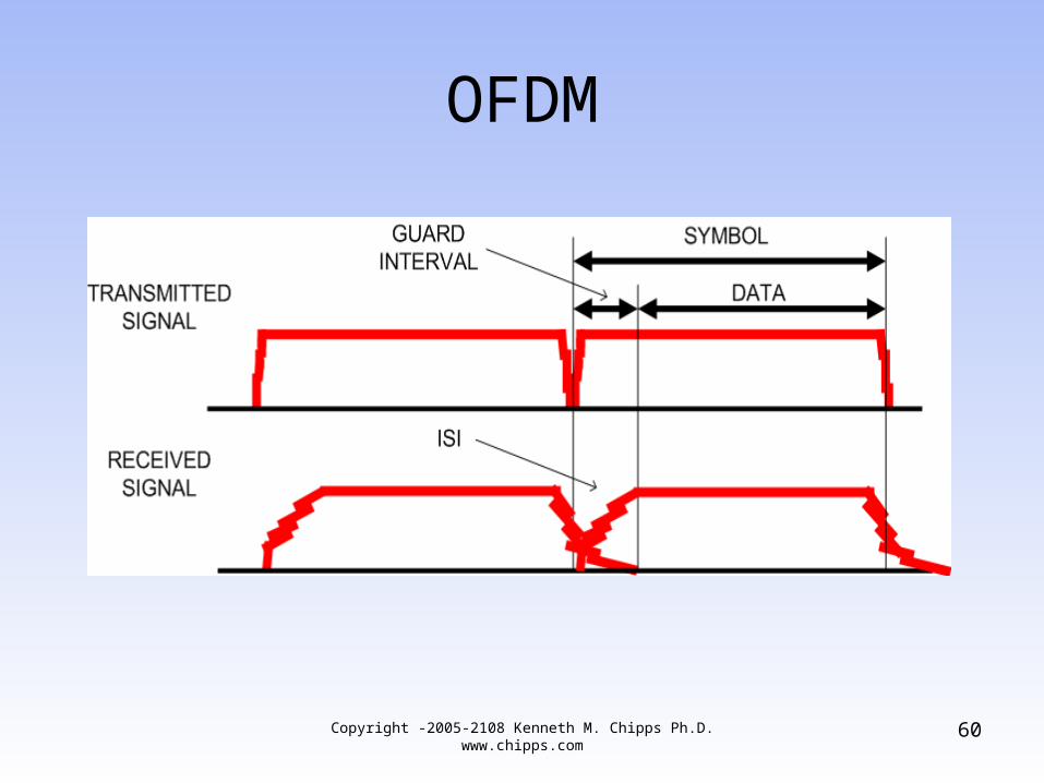
• In ISI the echoes of one signal are seen as interference by a later signal
• OFDM overcomes this problem by the use of a Guard Interval period at the beginning of a signal or symbol
• The Guard Interval is used to account for that part of the symbol that is damaged by the ISI
• What follows the Guard Interval is the dataCopyright -2005-2108 Kenneth M. Chipps Ph.D.
www.chipps.com59
OFDM
Copyright -2005-2108 Kenneth M. Chipps Ph.D. www.chipps.com
60
OFDM
• OFDM is a non line of sight modulation method
• This is a distinct advantage over DSSS• The modulation used with OFDM depends
on the signal’s data rate
Copyright -2005-2108 Kenneth M. Chipps Ph.D. www.chipps.com
61
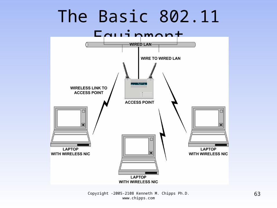
The Basic 802.11 Equipment
• Only two parts are needed to create a 802.11b network
• The parts are– Access Point– NIC
• Such a network looks like this
62Copyright -2005-2108 Kenneth M. Chipps Ph.D. www.chipps.com
The Basic 802.11 Equipment
63Copyright -2005-2108 Kenneth M. Chipps Ph.D. www.chipps.com
What is an Access Point
• An access point or AP provides a means to connect a wireless device to a wired network
• It is the intermediary in the connection between the wired and wireless networks
64Copyright -2005-2108 Kenneth M. Chipps Ph.D. www.chipps.com
Access Point Operating Modes
• An AP can operate in one of three modes– Root Mode– Repeater Mode– Bridge Mode
65Copyright -2005-2108 Kenneth M. Chipps Ph.D. www.chipps.com
Root Mode
• In root mode the AP is connected directly to the wired network by attaching a cable to the Ethernet port in the AP and to a hub or switch on the wired network
• This is the default configuration for most access points
• In root mode one access point can talk to another one by going through the wires they both share
66Copyright -2005-2108 Kenneth M. Chipps Ph.D. www.chipps.com
Root Mode
• This type of conversation is required when a device communicating with one AP needs to talk to a device that is attached to another AP on the same wired network
• APs also use this connection to coordinate roaming among access points similarly configured
• In this mode an AP is operating as a bridge at layer 2 of the OSI model
67Copyright -2005-2108 Kenneth M. Chipps Ph.D. www.chipps.com
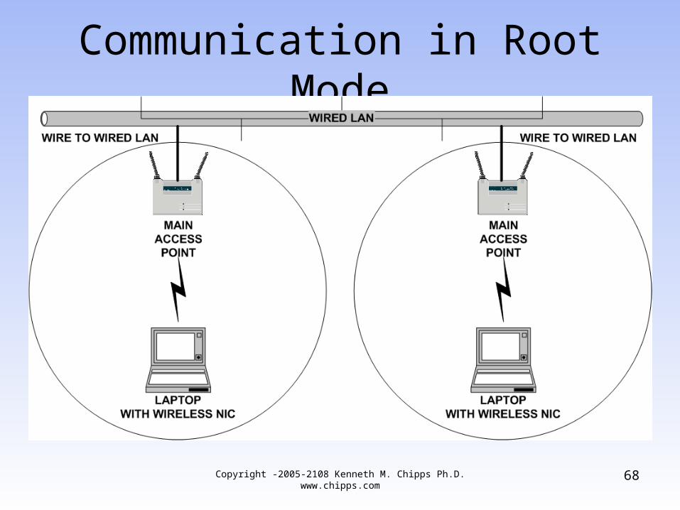
Communication in Root Mode
68Copyright -2005-2108 Kenneth M. Chipps Ph.D. www.chipps.com
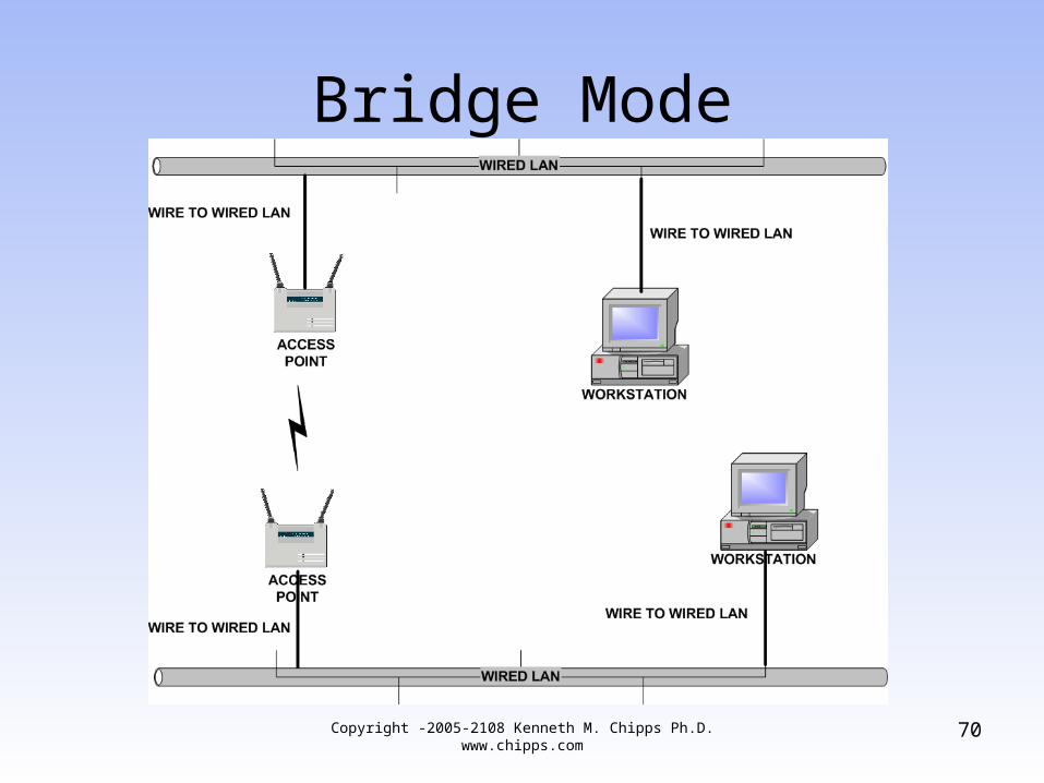
Bridge Mode
• In this mode the AP operates like a bridge• A bridge is a way to connect two physical
parts of the same network together• Devices do not connect to bridges
69Copyright -2005-2108 Kenneth M. Chipps Ph.D. www.chipps.com
Bridge Mode
70Copyright -2005-2108 Kenneth M. Chipps Ph.D. www.chipps.com
Repeater Mode
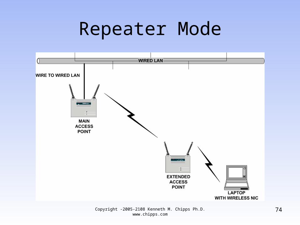
• In repeater mode an additional access point is used to wirelessly extend the range of an existing access point
• This is done by having the clients at the extended distance connect wirelessly to the AP that is located away from the main access point
• This extended access point then connects wirelessly back to the main AP
71Copyright -2005-2108 Kenneth M. Chipps Ph.D. www.chipps.com
Repeater Mode
• The cell of the extended AP must overlap the cell of the main AP by 50 percent for this to work effectively
• The throughput of the wireless LAN – Local Area Network is cut significantly as the repeater must receive and retransmit each frame on the channel
• This basically doubles the traffic on the wireless media
Copyright -2005-2108 Kenneth M. Chipps Ph.D. www.chipps.com
72
Repeater Mode
• In general, to setup an AP for this role all that is required is to switch the AP to repeater mode, then set the SSID, which is the name of the wireless network, to match the SSID of the root mode AP
• Not all APs have a repeater mode
73Copyright -2005-2108 Kenneth M. Chipps Ph.D. www.chipps.com
Repeater Mode
74Copyright -2005-2108 Kenneth M. Chipps Ph.D. www.chipps.com
Access Point Management
• There is an ongoing argument concerning the way to manage an increasing number of access points
• As organizations add more and more access points there is a need to limit the amount of time required to mange these
• The suggested method is to use limited access points and wireless switches
75Copyright -2005-2108 Kenneth M. Chipps Ph.D. www.chipps.com
Access Point Management
• The term wireless switch is an unfortunate marketing term for taking all of the intelligence out of the access points, which is fine, and placing it in a single box at the junction point between the wireless and wired networks
Copyright -2005-2108 Kenneth M. Chipps Ph.D. www.chipps.com
76
Access Point Management
• Here is a discussion on this from Ortronics– Centralized wireless LANs use a wireless
controller to manage, process, and configure your radio frequency (RF) environment
– The access points, sometimes called "thin APs", communicate directly with the central controller located at the edge of the wired network
77Copyright -2005-2108 Kenneth M. Chipps Ph.D. www.chipps.com
Access Point Management
– Unlike a traditional more costly access point, all the functionality and intelligence is offloaded to the controller
– This provides a single point of administration for various policies relating to security, intrusion detection, user roles, and software upgrade
Copyright -2005-2108 Kenneth M. Chipps Ph.D. www.chipps.com
78
Access Point Management
– A traditional wireless LAN uses decentralized "fat" access points that perform all the network processing and functionality in each unit
– Manual configuration of each access point consumes valuable network administrator time to manually set power levels, channel, security, and many other configurable parameters
79Copyright -2005-2108 Kenneth M. Chipps Ph.D. www.chipps.com
Access Point Management
– In larger deployments, this could lead to configuration mistakes that go unnoticed causing performance problems or network security risks
– Firmware upgrades, to fix or add functionality, can be a painstaking process with as few as six access points
– Each AP will most likely have to be individually updated and touched by the administrator if remote upgrade tools are not available
Copyright -2005-2108 Kenneth M. Chipps Ph.D. www.chipps.com
80
Access Point Management
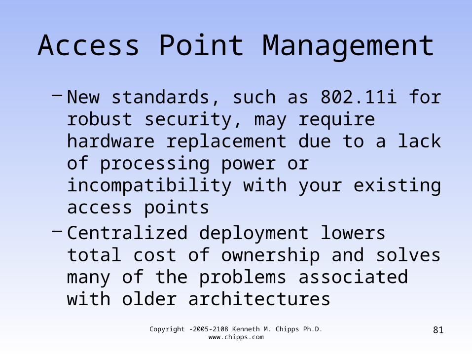
– New standards, such as 802.11i for robust security, may require hardware replacement due to a lack of processing power or incompatibility with your existing access points
– Centralized deployment lowers total cost of ownership and solves many of the problems associated with older architectures
81Copyright -2005-2108 Kenneth M. Chipps Ph.D. www.chipps.com
Access Point Management
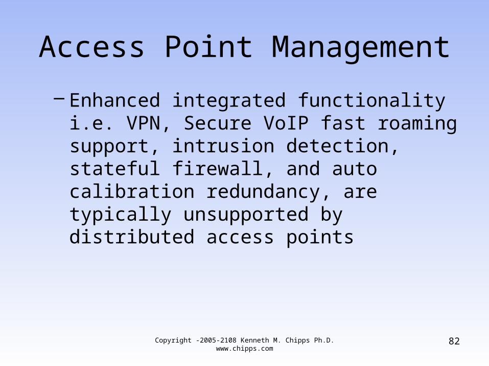
– Enhanced integrated functionality i.e. VPN, Secure VoIP fast roaming support, intrusion detection, stateful firewall, and auto calibration redundancy, are typically unsupported by distributed access points
Copyright -2005-2108 Kenneth M. Chipps Ph.D. www.chipps.com
82
Access Point Management
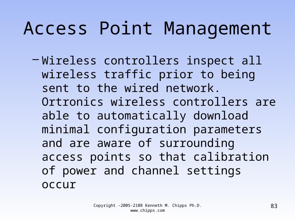
– Wireless controllers inspect all wireless traffic prior to being sent to the wired network. Ortronics wireless controllers are able to automatically download minimal configuration parameters and are aware of surrounding access points so that calibration of power and channel settings occur
Copyright -2005-2108 Kenneth M. Chipps Ph.D. www.chipps.com
83
Example Access Point
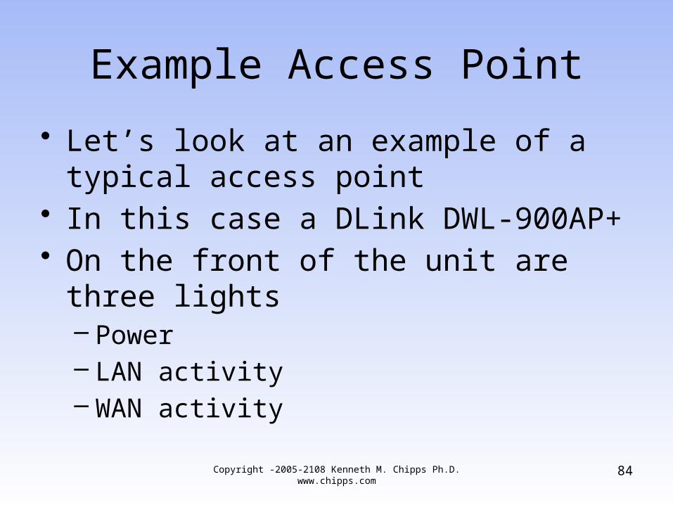
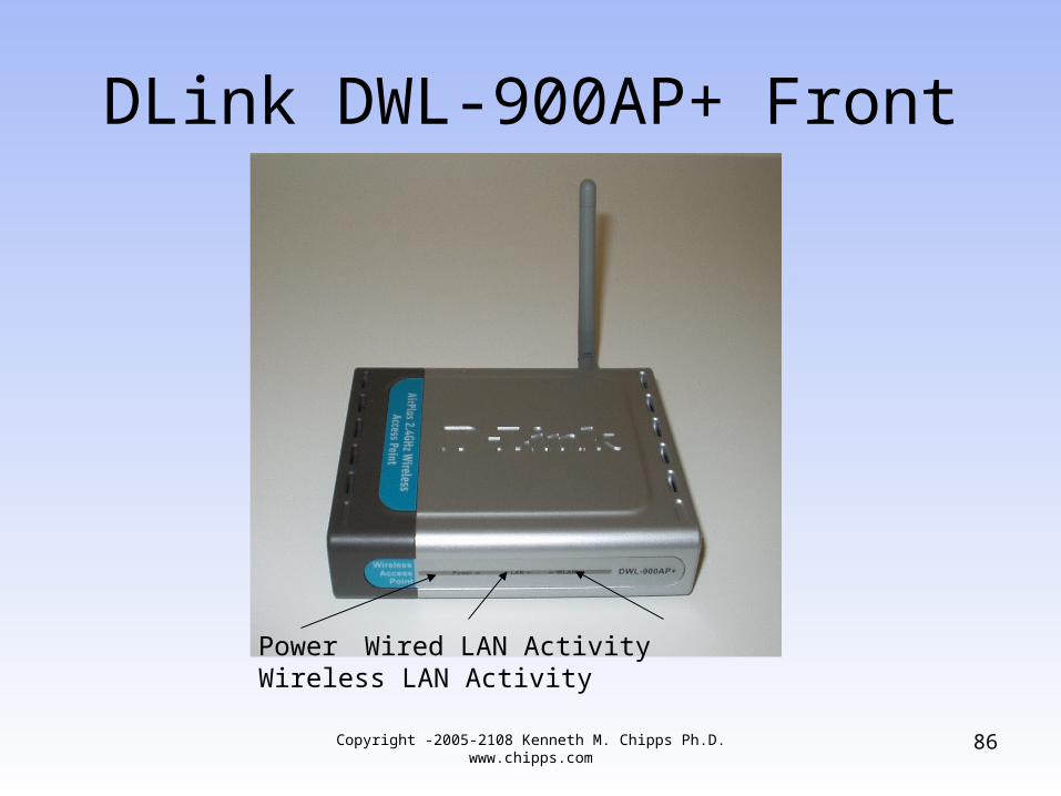
• Let’s look at an example of a typical access point
• In this case a DLink DWL-900AP+• On the front of the unit are three lights
– Power– LAN activity– WAN activity
84Copyright -2005-2108 Kenneth M. Chipps Ph.D. www.chipps.com
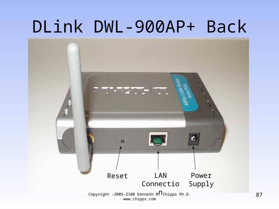
Example Access Point
• On the back– Reset button– Wired LAN connection– Power supply connection
Copyright -2005-2108 Kenneth M. Chipps Ph.D. www.chipps.com
85
DLink DWL-900AP+ Front
86
Power Wired LAN Activity Wireless LAN Activity
Copyright -2005-2108 Kenneth M. Chipps Ph.D. www.chipps.com
DLink DWL-900AP+ Back
87
LANConnection
Reset Power Supply
Copyright -2005-2108 Kenneth M. Chipps Ph.D. www.chipps.com
Setup
• Once the physical connections are made the access point must be configured
• In this example the DLink DWL-900AP+ is setup using the built-in setup program as seen in the pages that follow
• In the first few screenshots the setup wizard is being used
88Copyright -2005-2108 Kenneth M. Chipps Ph.D. www.chipps.com
Setup
• Then the normal method is shown where the individual setup pages are selected
• Typical configuration steps include– Login– Set a password– Select the SSID and channel
Copyright -2005-2108 Kenneth M. Chipps Ph.D. www.chipps.com
89
Setup
– Enable WEP– Set an IP address and subnet mask for the AP– Setup the built-in DHCP server– Set the operating mode– Adjust the performance– Setup MAC filtering
90Copyright -2005-2108 Kenneth M. Chipps Ph.D. www.chipps.com
Setup
• After the AP is in operation the status of the network can be checked through the AP’s management program
Copyright -2005-2108 Kenneth M. Chipps Ph.D. www.chipps.com
91

Login
92Copyright -2005-2108 Kenneth M. Chipps Ph.D. www.chipps.com
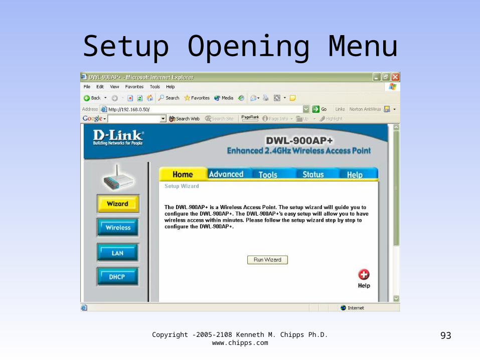
Setup Opening Menu
93Copyright -2005-2108 Kenneth M. Chipps Ph.D. www.chipps.com
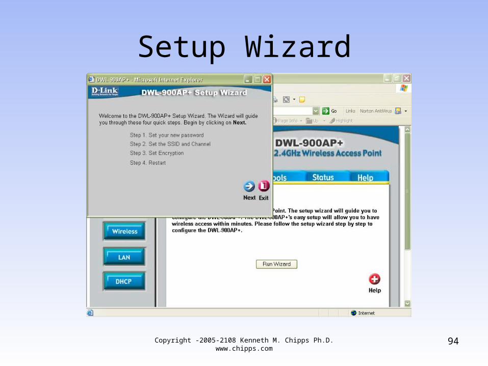
Setup Wizard
94Copyright -2005-2108 Kenneth M. Chipps Ph.D. www.chipps.com
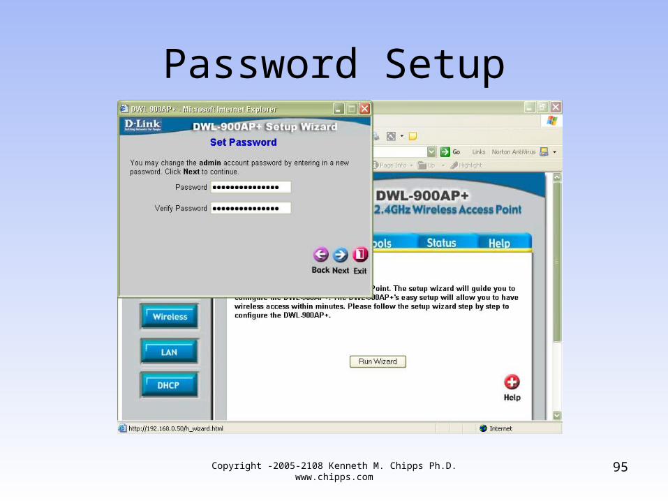
Password Setup
95Copyright -2005-2108 Kenneth M. Chipps Ph.D. www.chipps.com
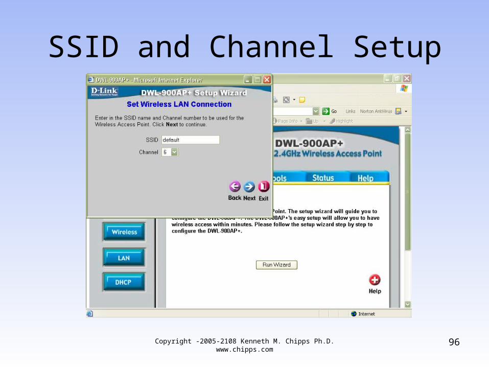
SSID and Channel Setup
96Copyright -2005-2108 Kenneth M. Chipps Ph.D. www.chipps.com
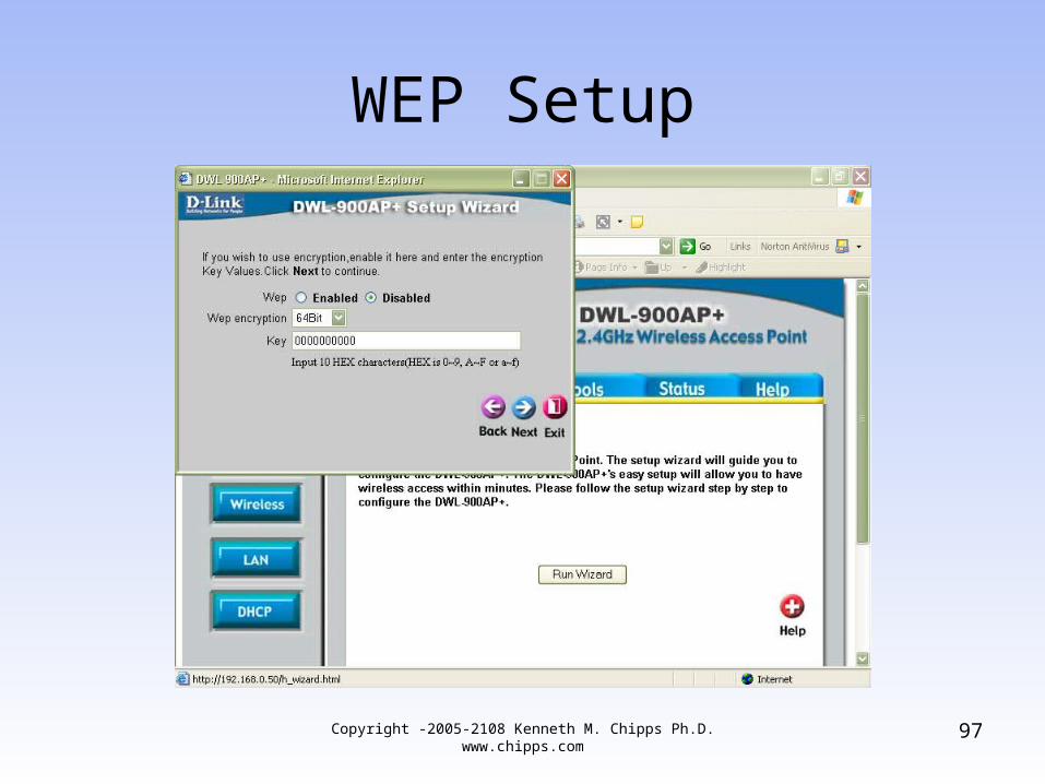
WEP Setup
97Copyright -2005-2108 Kenneth M. Chipps Ph.D. www.chipps.com
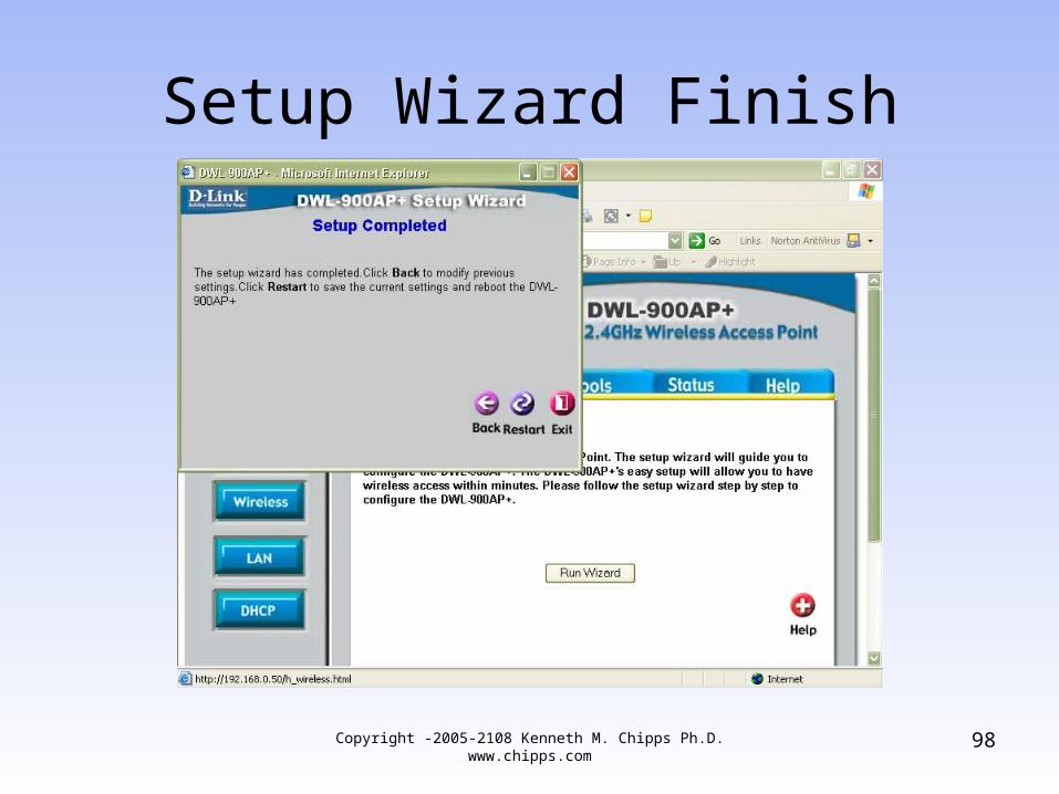
Setup Wizard Finish
98Copyright -2005-2108 Kenneth M. Chipps Ph.D. www.chipps.com
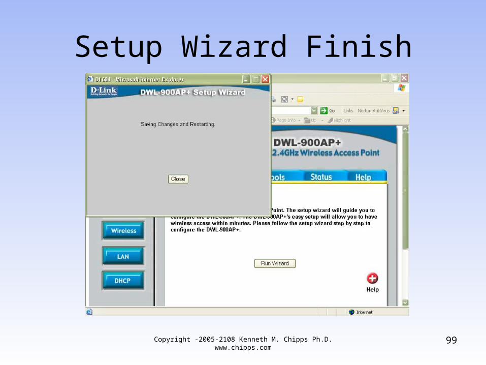
Setup Wizard Finish
99Copyright -2005-2108 Kenneth M. Chipps Ph.D. www.chipps.com
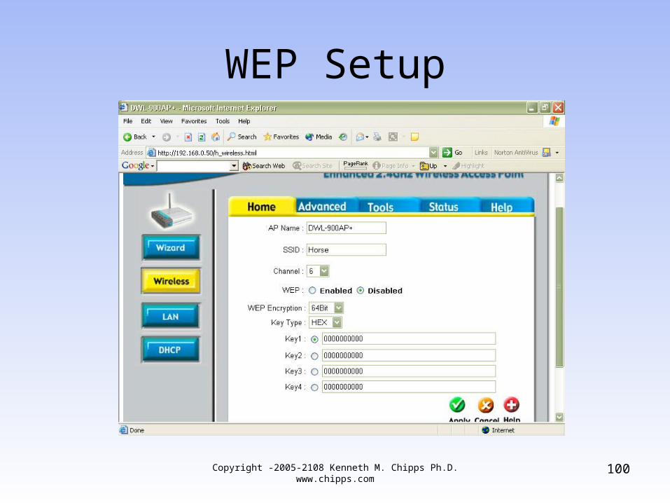
WEP Setup
100Copyright -2005-2108 Kenneth M. Chipps Ph.D. www.chipps.com
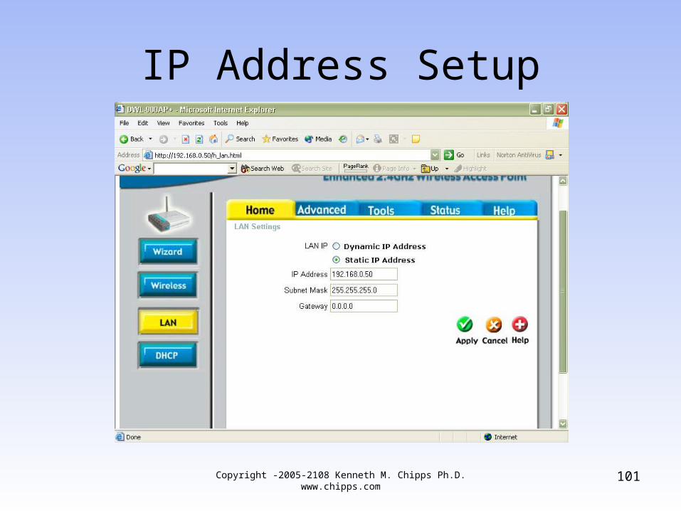
IP Address Setup
101Copyright -2005-2108 Kenneth M. Chipps Ph.D. www.chipps.com
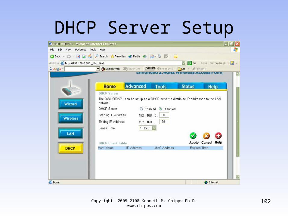
DHCP Server Setup
102Copyright -2005-2108 Kenneth M. Chipps Ph.D. www.chipps.com
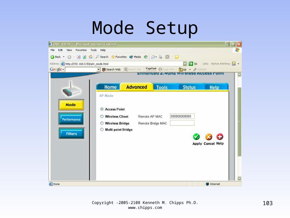
Mode Setup
103Copyright -2005-2108 Kenneth M. Chipps Ph.D. www.chipps.com
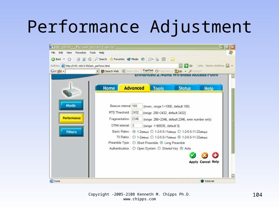
Performance Adjustment
104Copyright -2005-2108 Kenneth M. Chipps Ph.D. www.chipps.com
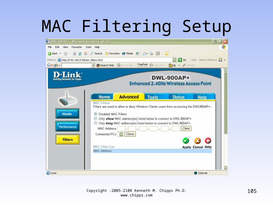
MAC Filtering Setup
105Copyright -2005-2108 Kenneth M. Chipps Ph.D. www.chipps.com
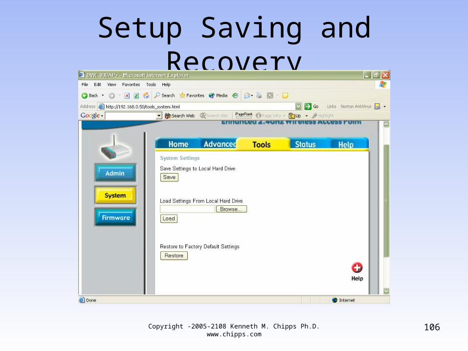
Setup Saving and Recovery
106Copyright -2005-2108 Kenneth M. Chipps Ph.D. www.chipps.com
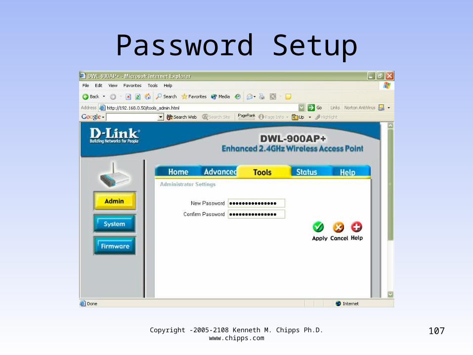
Password Setup
107Copyright -2005-2108 Kenneth M. Chipps Ph.D. www.chipps.com
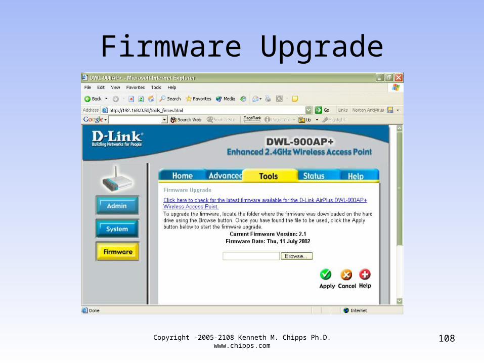
Firmware Upgrade
108Copyright -2005-2108 Kenneth M. Chipps Ph.D. www.chipps.com
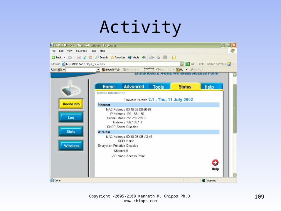
Activity
109Copyright -2005-2108 Kenneth M. Chipps Ph.D. www.chipps.com
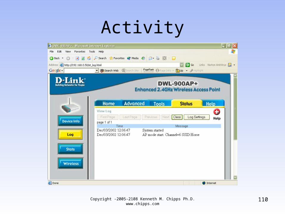
Activity
110Copyright -2005-2108 Kenneth M. Chipps Ph.D. www.chipps.com
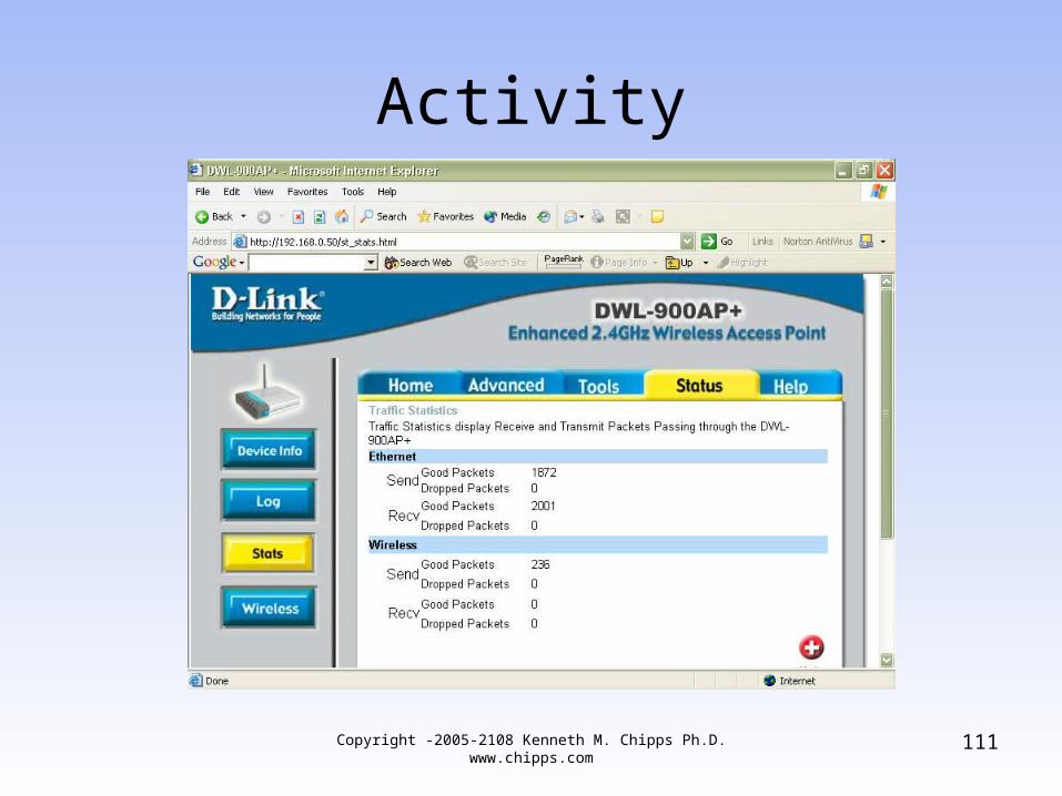
Activity
111Copyright -2005-2108 Kenneth M. Chipps Ph.D. www.chipps.com
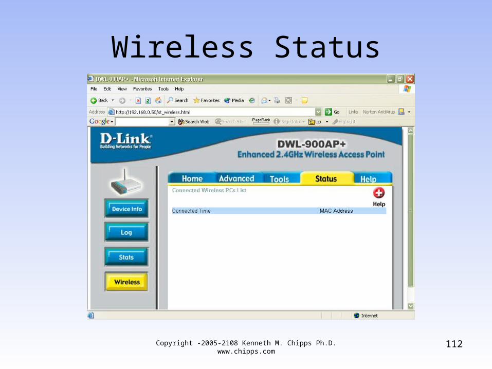
Wireless Status
112Copyright -2005-2108 Kenneth M. Chipps Ph.D. www.chipps.com

Help Topics
113Copyright -2005-2108 Kenneth M. Chipps Ph.D. www.chipps.com
Wireless NIC
• The next piece of equipment needed when creating a wireless network based on the 802.11 standards is a NIC – Network Interface Card
• Recall that as in a wired network the NIC is used to allow a device to connect to the network
• This is the link between a device and the network
114Copyright -2005-2108 Kenneth M. Chipps Ph.D. www.chipps.com
Wireless NIC
• It puts information onto the network• It takes information off of the network
Copyright -2005-2108 Kenneth M. Chipps Ph.D. www.chipps.com
115
NIC Forms
• Wireless NICs come in several forms including these typical ones– PCMCIA– Adaptor Card– USB Port Adaptor– Compact Flash– Wired to Wireless Bridge
116Copyright -2005-2108 Kenneth M. Chipps Ph.D. www.chipps.com
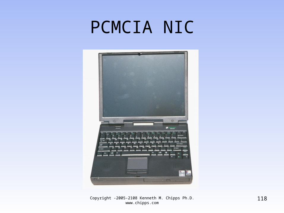
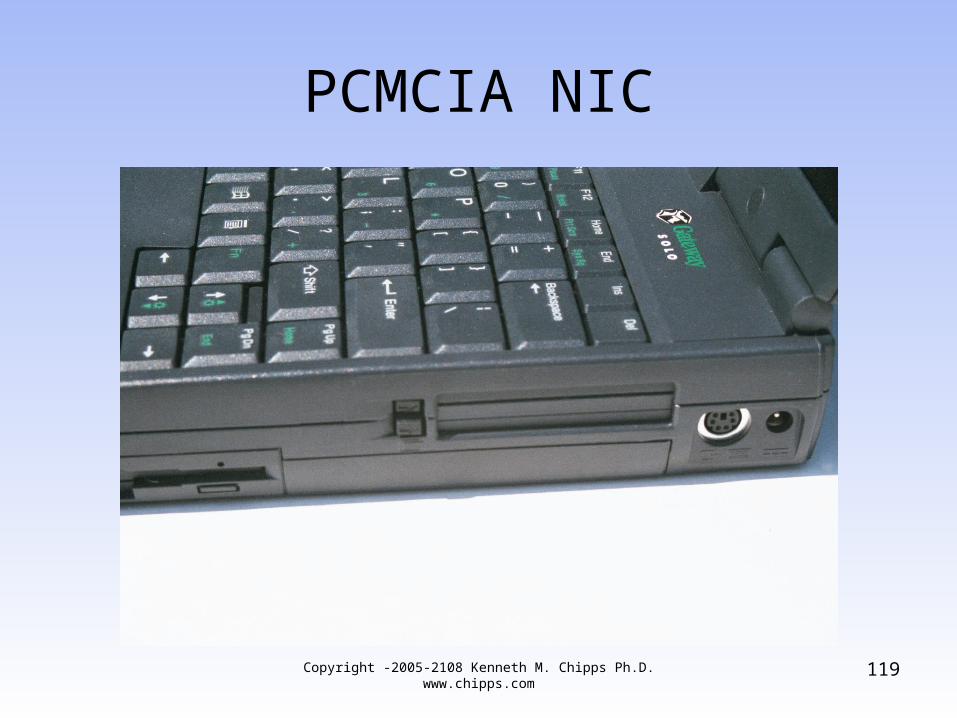
PCMCIA Form
• PCMCIA is the format designed for laptop computers
• As in
117Copyright -2005-2108 Kenneth M. Chipps Ph.D. www.chipps.com
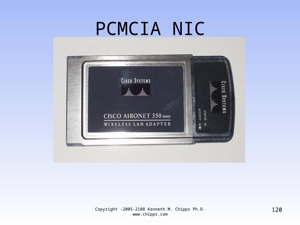
PCMCIA NIC
118Copyright -2005-2108 Kenneth M. Chipps Ph.D. www.chipps.com
PCMCIA NIC
119Copyright -2005-2108 Kenneth M. Chipps Ph.D. www.chipps.com
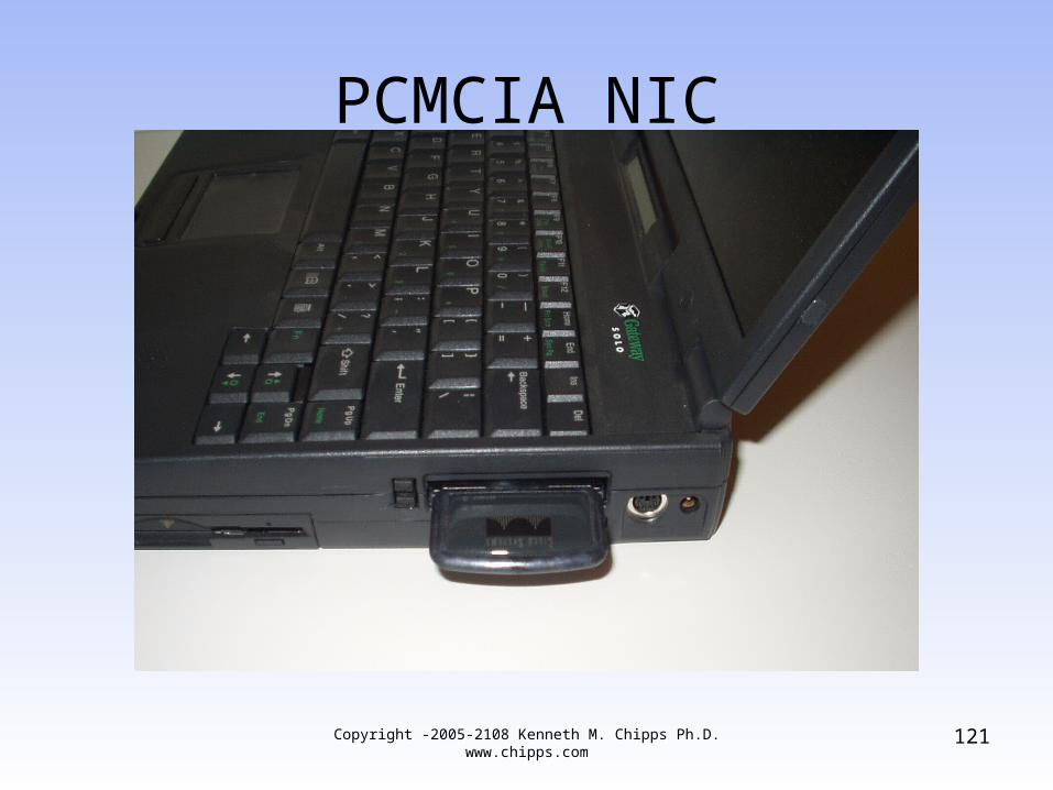
PCMCIA NIC
120Copyright -2005-2108 Kenneth M. Chipps Ph.D. www.chipps.com
PCMCIA NIC
121Copyright -2005-2108 Kenneth M. Chipps Ph.D. www.chipps.com
Desktop Wireless NIC
• The PCMCIA form is sometimes used to make a NIC for use in a desktop computer
• When used this way the PCMCIA card is inserted into a carrier that will attach to the bus in a desktop computer, such as the PCI bus
• For example
122Copyright -2005-2108 Kenneth M. Chipps Ph.D. www.chipps.com
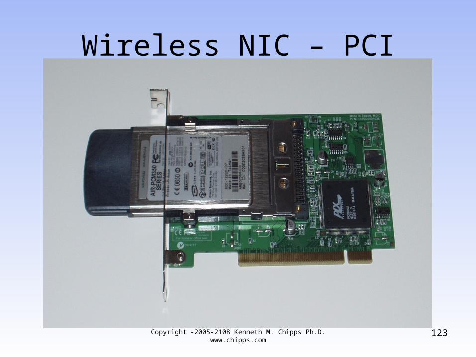
Wireless NIC – PCI
123Copyright -2005-2108 Kenneth M. Chipps Ph.D. www.chipps.com
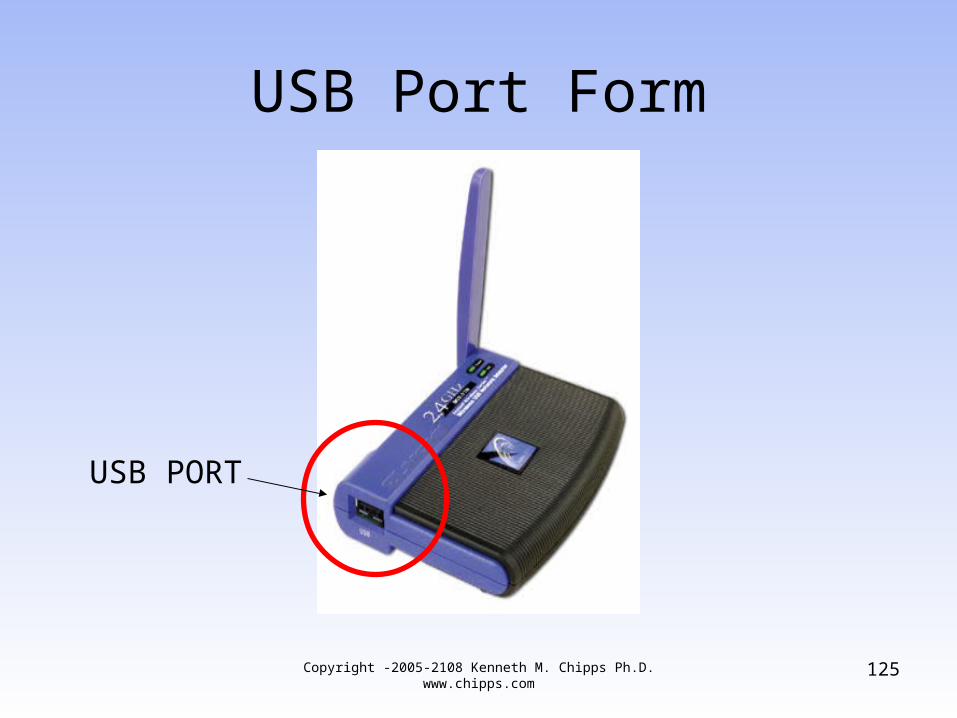
USB Port Form
• A new form for a NIC is using the USB port to attach the NIC to the computer
• As in
124Copyright -2005-2108 Kenneth M. Chipps Ph.D. www.chipps.com
USB Port Form
125
USB PORT
Copyright -2005-2108 Kenneth M. Chipps Ph.D. www.chipps.com
Wireless NIC Setup
• The setup for a wireless NIC mirrors that of the access point for the most part
• In this example, after the two opening screens the following is seen– System parameters– Radio frequency setup– Performance setup– Security setup
126Copyright -2005-2108 Kenneth M. Chipps Ph.D. www.chipps.com
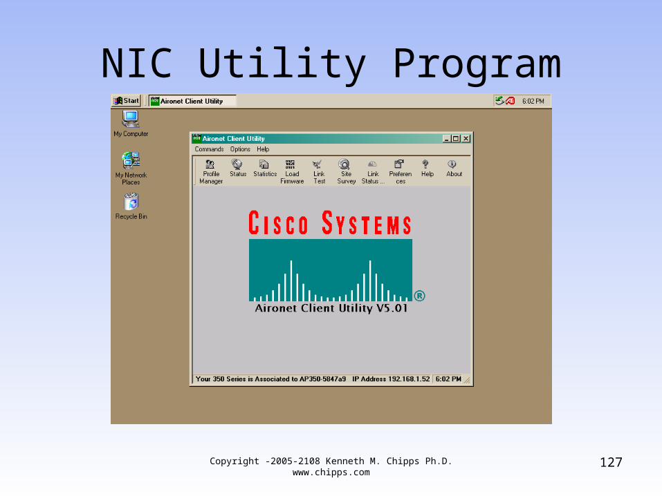
NIC Utility Program
127Copyright -2005-2108 Kenneth M. Chipps Ph.D. www.chipps.com
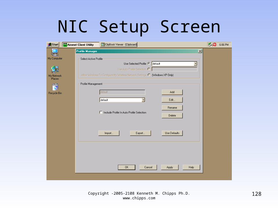
NIC Setup Screen
128Copyright -2005-2108 Kenneth M. Chipps Ph.D. www.chipps.com
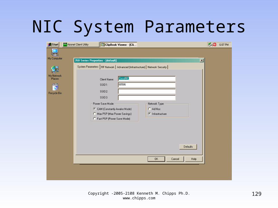
NIC System Parameters
129Copyright -2005-2108 Kenneth M. Chipps Ph.D. www.chipps.com
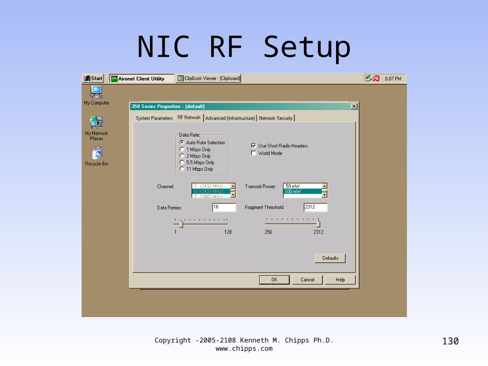
NIC RF Setup
130Copyright -2005-2108 Kenneth M. Chipps Ph.D. www.chipps.com
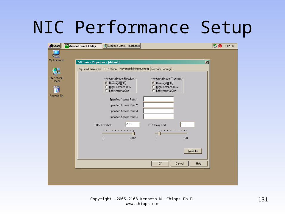
NIC Performance Setup
131Copyright -2005-2108 Kenneth M. Chipps Ph.D. www.chipps.com
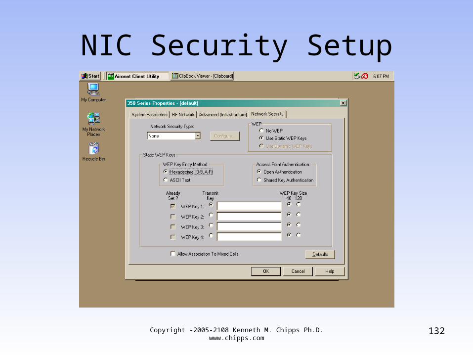
NIC Security Setup
132Copyright -2005-2108 Kenneth M. Chipps Ph.D. www.chipps.com
Creating an 802.11 Network
• There are two main ways to create an 802.11 network
• These are– Ad Hoc– Infrastructure
• Each of these will be discussed in detail below
133Copyright -2005-2108 Kenneth M. Chipps Ph.D. www.chipps.com
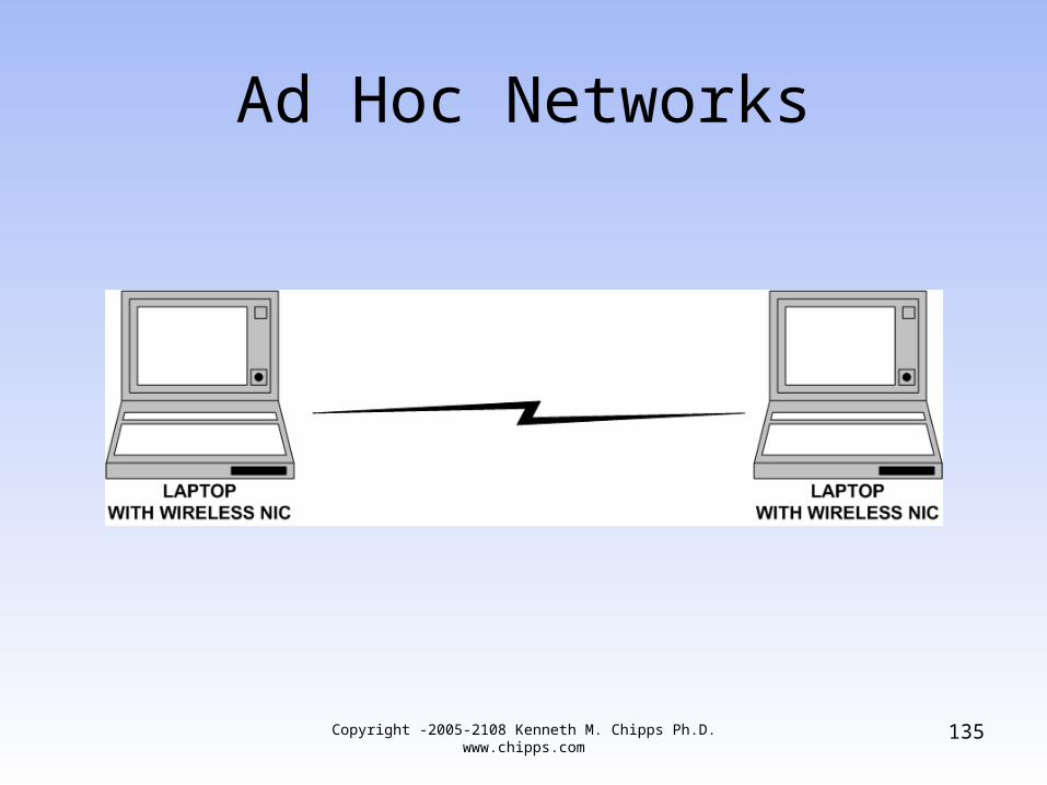
Ad Hoc Networks
• The most basic way to create an 802.11 network is to just connect two computers together wirelessly
• In this case all nodes talk to each other directly
• This method is called an Ad Hoc network• It is also called an Independent BSS at
times
134Copyright -2005-2108 Kenneth M. Chipps Ph.D. www.chipps.com
Ad Hoc Networks
135Copyright -2005-2108 Kenneth M. Chipps Ph.D. www.chipps.com
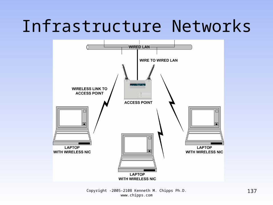
Infrastructure Networks
• The second, and more common way, of creating a 802.11 network is to connect everything together using access points
• For example
136Copyright -2005-2108 Kenneth M. Chipps Ph.D. www.chipps.com
Infrastructure Networks
137Copyright -2005-2108 Kenneth M. Chipps Ph.D. www.chipps.com
Infrastructure Networks
• Once it is decided an infrastructure network is the design to use the next decision for this type of network is how wide of an area should it cover
• The options are– BSS– ESS
138Copyright -2005-2108 Kenneth M. Chipps Ph.D. www.chipps.com
BSS or BSA
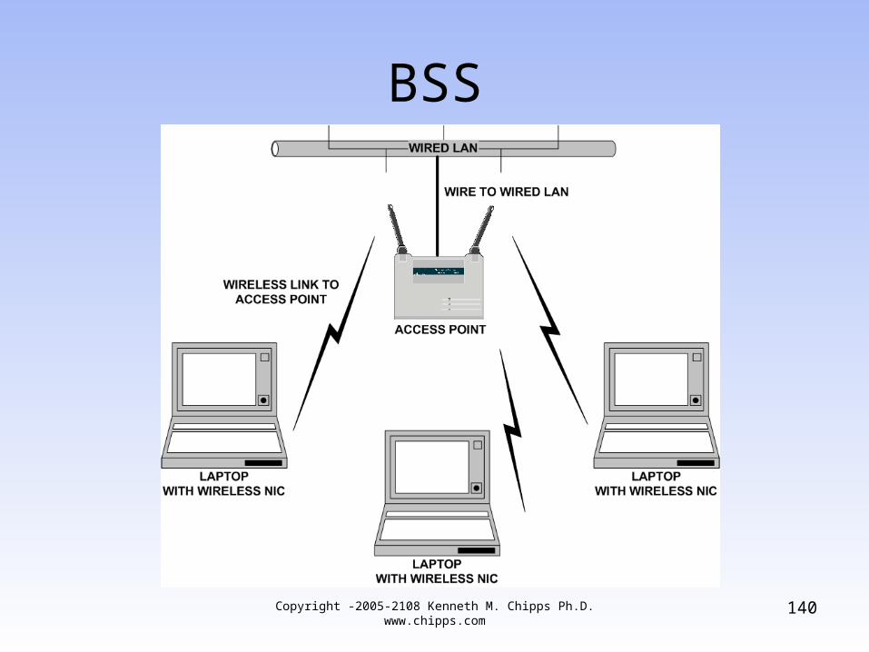
• The BSS is a Basic Service Set or sometimes called the base service area or Infrastructure BSS
• A BSS contains a single access point and the devices that connect through it
139Copyright -2005-2108 Kenneth M. Chipps Ph.D. www.chipps.com
BSS
140Copyright -2005-2108 Kenneth M. Chipps Ph.D. www.chipps.com
ESS or ESA
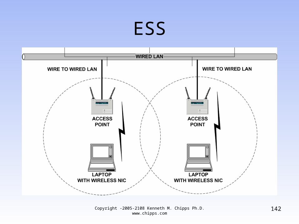
• When individual access points talk to each other, we have an Extended Service Set or ESS or it can be called an extended service area
• This is a set of BSSs chained together with a backbone network called a Distribution Set or DS
• Since access points operate as bridges, this backbone must be at layer 2 as well
141Copyright -2005-2108 Kenneth M. Chipps Ph.D. www.chipps.com
ESS
142Copyright -2005-2108 Kenneth M. Chipps Ph.D. www.chipps.com
Infrastructure Network
• Now that we know how large an area to cover, the next thing to cover is how an 802.11b network actually works
143Copyright -2005-2108 Kenneth M. Chipps Ph.D. www.chipps.com
SSID
• All devices on the wireless network must use the same name or SSID – Service Set Identifier
• This name can be from 2 to 32 characters long
• The SSID is sent as part of the
144Copyright -2005-2108 Kenneth M. Chipps Ph.D. www.chipps.com
SSID
– Beacon– Probe request– Probe response– Association request– Reassociation request
• As the SSID is sent out by the access point on a regular basis, announcing this can be a security risk
Copyright -2005-2108 Kenneth M. Chipps Ph.D. www.chipps.com
145
SSID
• The broadcasting of the SSID can usually be turned off
Copyright -2005-2108 Kenneth M. Chipps Ph.D. www.chipps.com
146
How a Station Joins a WLAN
• A station needs to join a wireless LAN whenever it– First powers on– Enters a Basic Service Set area
• To successfully do this the station must first receive synchronization information
• This can be done through– Passive scanning– Active scanning
147Copyright -2005-2108 Kenneth M. Chipps Ph.D. www.chipps.com
Passive Scanning
• In passive scanning a station listens for a specific period of time on each channel for beacon frames sent out by an AP - access point when in infrastructure mode and by stations when they are in ad hoc mode
• For identifications APs send the SSID in the beacon
• The listening station looks for a beacon with the same SSID as it has
148Copyright -2005-2108 Kenneth M. Chipps Ph.D. www.chipps.com
Passive Scanning
• When multiple access points transmit a station’s SSID, the station will join the one with the strongest signal and lowest bit error rate
• Stations continue passive scanning so as to facilitate reassociation and roaming
Copyright -2005-2108 Kenneth M. Chipps Ph.D. www.chipps.com
149
Active Scanning
• In active scanning a station transmits a probe request frame
• The probe request frame includes the SSID of the network the station wishes to join or the broadcast SSID
• It then waits for a probe response frame from an access point, these are basically the same as beacons
150Copyright -2005-2108 Kenneth M. Chipps Ph.D. www.chipps.com
How a Station Connects
• The general station authentication sequence is– Client broadcasts a probe request frame on
every channel– Access points within range respond with a
probe response frame– The client decides which access point to
connect to based on signal strength and data rate
– The client sends an authentication request151Copyright -2005-2108 Kenneth M. Chipps Ph.D.
www.chipps.com
How a Station Connects
– The access points answers with an authentication reply
– Once authenticated, the client must associate by sending an association request frame to the access point
– The access point will reply with an association request
– The client can now send and receive traffic
Copyright -2005-2108 Kenneth M. Chipps Ph.D. www.chipps.com
152
Authentication and Association
• After the station finds an access point it must exchange authentication information with the access point
• After authentication the station associates itself with the access point
153Copyright -2005-2108 Kenneth M. Chipps Ph.D. www.chipps.com
Authentication
• The first step in connecting to a wireless LAN is authentication
• In a wired network this is implicit for any station that can physically connect a cable to the network
• In a wireless network, in this step a station identifies itself to the network
154Copyright -2005-2108 Kenneth M. Chipps Ph.D. www.chipps.com
Authentication
• In most cases this step is automatic in that all stations that request authentication are authenticated, such as when a brand new station is first turned on
• The authentication is performed by the AP or it can be turned over to a RADIUS server on the network
Copyright -2005-2108 Kenneth M. Chipps Ph.D. www.chipps.com
155
Authentication
• This authentication process is a one way street
• Only stations authenticate to an access point
• The access point does not need to authenticate itself back to the station
• This does nothing then to prevent unauthorized access points from being introduced into the network
156Copyright -2005-2108 Kenneth M. Chipps Ph.D. www.chipps.com
Association
• Once authenticated, the device next associates itself with the network
• Once associated the station is allowed to send data through the access point to the network
157Copyright -2005-2108 Kenneth M. Chipps Ph.D. www.chipps.com
Authentication and Association
• There are three possible states of the combination of authentication and association
• These are– Unauthenticated and Unassociated– Authenticated and Unassociated– Authenticated and Associated
158Copyright -2005-2108 Kenneth M. Chipps Ph.D. www.chipps.com
Unauthenticated Unassociated
• In this state the device is disconnected from the network
• It can do nothing through the network in either direction
• The station is blocked before the access point
159Copyright -2005-2108 Kenneth M. Chipps Ph.D. www.chipps.com
Authenticated Unassociated
• The station is authenticated to the access point
• But it cannot send or receive from the network
• The station is halfway through the access point
160Copyright -2005-2108 Kenneth M. Chipps Ph.D. www.chipps.com
Authenticated Associated
• The station is on the network• It can send and receive data• The station is all the way through the
access point
161Copyright -2005-2108 Kenneth M. Chipps Ph.D. www.chipps.com
Authentication Methods
• The 802.11 standard specifies two authentication methods– Open System
• This is a null authentication process• In that any client can associate with any access
point
– Shared Key• Devices must have identical WEP settings to
communicate
162Copyright -2005-2108 Kenneth M. Chipps Ph.D. www.chipps.com
Open System Authentication
• Open System authentication is the default method for 802.11
• Open System requires no configuration
163Copyright -2005-2108 Kenneth M. Chipps Ph.D. www.chipps.com
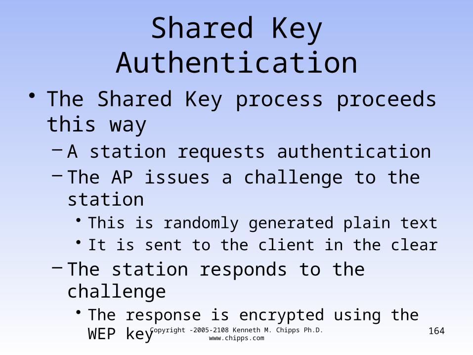
Shared Key Authentication
• The Shared Key process proceeds this way– A station requests authentication– The AP issues a challenge to the station
• This is randomly generated plain text• It is sent to the client in the clear
– The station responds to the challenge• The response is encrypted using the WEP key
164Copyright -2005-2108 Kenneth M. Chipps Ph.D. www.chipps.com
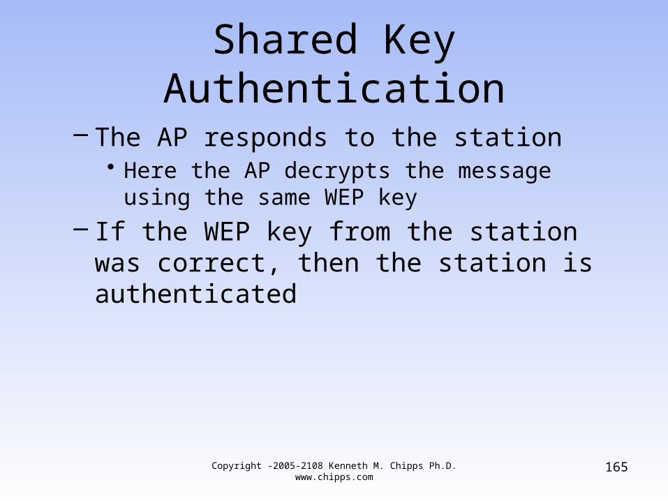
Shared Key Authentication
– The AP responds to the station• Here the AP decrypts the message using the same
WEP key
– If the WEP key from the station was correct, then the station is authenticated
Copyright -2005-2108 Kenneth M. Chipps Ph.D. www.chipps.com
165
Transmission Stage
• Finally at the transmission stage the station can send and receive data frames through the AP
• Once transmission begins the wireless aspect of the local network is transparent to the application and user
166Copyright -2005-2108 Kenneth M. Chipps Ph.D. www.chipps.com
Types of Media Access Control
• At the data link layer there are two methods available to control access– The DCF – Distributed Coordination Function
is the basic method used– Within it there are two ways access to the
media is controlled• First, all stations cooperate with each other to
share the media, if they do not sense the media being used, they transmit, if a collision occurs, they try again
167Copyright -2005-2108 Kenneth M. Chipps Ph.D. www.chipps.com
Types of Media Access Control
• Second, to reserve the media RTS/CTS can be invoked
– The PCF – Point Coordination Function is available for use to enforce fair access by polling each station for traffic
• As DCF is the method commonly used it will be explained first and in more detail then PCF
Copyright -2005-2108 Kenneth M. Chipps Ph.D. www.chipps.com
168
Types of Media Access Control
• But before explaining how DCF works it is necessary to explain some of the underlying process it uses as it goes about its work of controlling access by stations to the media
169Copyright -2005-2108 Kenneth M. Chipps Ph.D. www.chipps.com
CSMA/CA
• As mentioned above when using DCF the stations first attempt to cooperate with each other
• But being a shared media a wireless 802.11 network must have a method to control fair access to the media and to deal with the inevitable collisions that will occur on a shared media
170Copyright -2005-2108 Kenneth M. Chipps Ph.D. www.chipps.com
CSMA/CA
• Unlike wire based Ethernet which attempts to detect collisions after the fact, CSMA/CA - Carrier Sense Multiple Access/ Collision Avoidance seeks to avoid them altogether
• This method works by listening for a transmission already on the air
• If it finds one, it waits
Copyright -2005-2108 Kenneth M. Chipps Ph.D. www.chipps.com
171
CSMA/CA
• If the medium is available for at least the time defined by the DIFS, distributed interframe space plus an additional random time, the station will transmit
• This additional random time is determined as a multiple of the slot time
• The contention window is used to determine the number of slot times to wait for the additional random time
172Copyright -2005-2108 Kenneth M. Chipps Ph.D. www.chipps.com
CSMA/CA
• Just in case another station does the same thing and transmits at the same time, the receiving station checks the CRC – Cyclic Redundancy Check
• If it is ok, then an ACK – Acknowledgement is sent back
• If not, then a retransmission takes place
173Copyright -2005-2108 Kenneth M. Chipps Ph.D. www.chipps.com
CSMA/CA
• After any unsuccessful transmission attempt, another backoff is performed with the contention window being a doubled in size
• This reduces the probability of a collision when there are multiple stations attempting to access the media’s channel
Copyright -2005-2108 Kenneth M. Chipps Ph.D. www.chipps.com
174
CSMA/CA
• The stations that deferred from channel access during the channel busy period do not select a new random backoff time
• They continue to count down the time of the deferred backoff in progress after sensing a channel as being idle again
175Copyright -2005-2108 Kenneth M. Chipps Ph.D. www.chipps.com
CSMA/CA
• Thus the stations that did not get to transmit because their random backoff time was larger than the backoff time of other stations, achieve a higher priority
• After each successful transmission, another random backoff is performed by the station that transmitted
• This is called the post-backoff, as this is done after, not before, a transmission
Copyright -2005-2108 Kenneth M. Chipps Ph.D. www.chipps.com
176
CSMA/CA
• It is up to the upper layers to decide when enough retransmission has occurred and abandon the effort
Copyright -2005-2108 Kenneth M. Chipps Ph.D. www.chipps.com
177
RTS/CTS
• The second method of DCF avoids collision by reserving the network before sending anything out onto it
• This is created by the station desiring to send data, first sending a RTS – Request to Send packet
• This is a short packet that contains the source and destination address and the duration of the following transmission
178Copyright -2005-2108 Kenneth M. Chipps Ph.D. www.chipps.com
RTS/CTS
• This frame reserves the radio link for transmission, as any stations that hear this frame remain silent
• The receiver responds with a CTS or Clear to Send
• This indicates the same duration information as was contained in the RTS packet
Copyright -2005-2108 Kenneth M. Chipps Ph.D. www.chipps.com
179
RTS/CTS
• Each station that receives either the RTS or CTS will set its virtual carrier sense or NAV indicator for the duration of the transmission
• If the CTS is not received, the sender of the RTS assumes a collision and starts over
180Copyright -2005-2108 Kenneth M. Chipps Ph.D. www.chipps.com
RTS/CTS
• Once the CTS frame is received and the data frame is sent, then the receiver will return an ACK to confirm a successful data transmission
• All of this RTS/CTS related traffic is just overhead that reduces data throughput
• RTS/CTS is used only in high use networks where there is significant contention for the wireless media
Copyright -2005-2108 Kenneth M. Chipps Ph.D. www.chipps.com
181
RTS/CTS
• For lower capacity networks, it is not required
• Whether RTS/CTS is used can be adjusted by adjusting the RTS threshold
• RTS/CTS is used for frames that are larger than the threshold
• For frames that are shorter, the frame is just sent using the method first described
182Copyright -2005-2108 Kenneth M. Chipps Ph.D. www.chipps.com
Wireless Security
• Security is a very current topic whenever wireless data networks are discussed
• Wireless security is a very current topic because of the large number of attacks that may be made against a wireless network
• Unfortunately there are few tools to use to defeat or even detect these attacks
Copyright -2005-2108 Kenneth M. Chipps Ph.D. www.chipps.com
183
Security Risks
• Current security risks include– Sniffing Attack
• This involves collecting enough data to decipher it
– Insertion, Interception, or Man in the Middle• Unauthorized users or access points are added to
the network
– Disassociation• The attacker sends disassociation frames to
access points with spoofed MAC addresses telling the access point to drop the connections
Copyright -2005-2108 Kenneth M. Chipps Ph.D. www.chipps.com
184
Security Risks
– Jamming• Denial of service can be done by using a radio
frequency signal generator or sweep generator to ruin the signal
– User to User• Users talking to each other without going through
an access point, such as using ad hoc network while on the wired network
– Brute Force Attack• Repeated attempts to guess a password
Copyright -2005-2108 Kenneth M. Chipps Ph.D. www.chipps.com
185
Security Risks
– Encryption Attack• Attacking the privacy protocols, such as WEP
– Misconfiguration• Improperly setup access points
– Lost or Stolen Device• This reveals the static WEP key or password
186Copyright -2005-2108 Kenneth M. Chipps Ph.D. www.chipps.com
Current Problems
• Authentication and the security of the data as it traverses the wireless network are the major problems right now with wireless networks
• Many solutions have been proposed• It remains to be seen what will end up, if
anything, being the dominate standard in this area
187Copyright -2005-2108 Kenneth M. Chipps Ph.D. www.chipps.com
Approach to Wireless Security
• There are three elements to securing a wireless network
• These are
188Copyright -2005-2108 Kenneth M. Chipps Ph.D. www.chipps.com
Approach to Wireless Security
– Authentication - Who Are You• EAP methods
– Encryption – Protect the Data from View• TKIP• AES
– Data Integrity – Protect the Data from Change• MIC
Copyright -2005-2108 Kenneth M. Chipps Ph.D. www.chipps.com
189
Encryption
• Encryption is a two part process– When the data is encrypted it is scrambled– When the data is decrypted it is returned to its
original form• A key is used to encrypt and to decrypt
– This is a unique value used by the encryption algorithm to alter the original data
Copyright -2005-2108 Kenneth M. Chipps Ph.D. www.chipps.com
190
No Security
• Open Authentication means there is no verification of the user or the device accessing the network
Copyright -2005-2108 Kenneth M. Chipps Ph.D. www.chipps.com
191
Stages of Wireless Security
• Wireless security is going through at least three stages
• These are– WEP– WPA– WPA2
192Copyright -2005-2108 Kenneth M. Chipps Ph.D. www.chipps.com
Stage 1
• In the first stage the only available security measures built-in to wireless networks was WEP
• Some additional security was available by filtering MAC addresses
• As neither WEP or MAC filtering proved to be adequate, users added IPSec based VPNs to this mix to add more security
193Copyright -2005-2108 Kenneth M. Chipps Ph.D. www.chipps.com
Stage 2
• In the second stage WEP was enhanced into WPA – Wireless Protected Access
194Copyright -2005-2108 Kenneth M. Chipps Ph.D. www.chipps.com
Stage 3
• The current stage is WPA2
195Copyright -2005-2108 Kenneth M. Chipps Ph.D. www.chipps.com
WEP
• WEP is an encryption algorithm that is used with the Shared Key authentication process for authenticating users as well as encrypting the data
• WEP relies on a secret key that is shared between a node and an access point
• Authentication is performed by requiring the station to have the same key as the access point
196Copyright -2005-2108 Kenneth M. Chipps Ph.D. www.chipps.com
WEP
• This key is also used to encrypt packets before they are transmitted
• When enabling encryption a key type must be selected
• This key can be in entered as ASCI or Hex– If ASCI the characters from 0 to 127 are
available– With Hex the characters are 0 to 9 and A to F
Copyright -2005-2108 Kenneth M. Chipps Ph.D. www.chipps.com
197
WEP
• Keys entered in ASCI are converted to hex• Consequently some systems will not talk
to each other if the keys are entered in ASCII
• Hex is much more reliable, but prone to errors on entry
• A single key that is shared between all mobile stations and access points is commonly used
198Copyright -2005-2108 Kenneth M. Chipps Ph.D. www.chipps.com
WEP
• WEP uses RC4, a stream-cipher, for encrypting data packets
• As such the security of the network is compromised if the key is revealed
• It uses symmetric keys• In other words a single key encrypts and
decrypts
Copyright -2005-2108 Kenneth M. Chipps Ph.D. www.chipps.com
199
WEP
• This is the basic problem of WEP• It uses a cipher not suitable for the
environment it operates in• The problem is that a stream cipher is not
suited for a wireless medium where packet interception is possible
• The RC4 cipher uses the combination of the shared key and an IV – Initialization Vector to produce a key for each packet
Copyright -2005-2108 Kenneth M. Chipps Ph.D. www.chipps.com
200
WEP Problems
• There are three primary problems with WEP– Manual key management is a major
management issue– No matter how many bits are used the data
can be copied off the air and deciphered, because the keystream is reused
– The CRC or integrity check is not secure
201Copyright -2005-2108 Kenneth M. Chipps Ph.D. www.chipps.com
But Still Use WEP
• Despite the many problems with WEP, it is still a useful security tool and should be used at all times
• It is true that the key can be compromised by a lost or stolen device
• It is also true that captured data can be decrypted
202Copyright -2005-2108 Kenneth M. Chipps Ph.D. www.chipps.com
VPN
• As WEP has proven incapable of fully securing wireless networks, many have proposed additional measures to layer security on top of what is available
• VPNs based on IPSec have pretty much become the default method used when WEP is not adequate
203Copyright -2005-2108 Kenneth M. Chipps Ph.D. www.chipps.com
WPA
• WPA offers stronger encryption than WEP• It does this by adding TKIP - Temporal Key
Integrity Protocol so that keys are rotated and encryption is increased
• In some cases existing equipment can be upgraded to WPA by a firmware upgrade
204Copyright -2005-2108 Kenneth M. Chipps Ph.D. www.chipps.com
TKIP
• TKIP is an upgrade to WEP designed to provide better security to existing networks
• Anything better, such as AES, will require upgraded hardware as the CPUs in the existing devices do not have the performance required
205Copyright -2005-2108 Kenneth M. Chipps Ph.D. www.chipps.com
TKIP
• TKIP differs from WEP in four respects– Enhanced message integrity check called
MIC or “Michael”– Periodic key replacement– A per packet key mixing capability– Replay protection
• The use of MIC helps to prevent forgery attacks
Copyright -2005-2108 Kenneth M. Chipps Ph.D. www.chipps.com
206
WPA Implementation
• WPA can be used in one of two ways• For a basic network WPA uses the PSK –
Pre-Shared Key mode• It is used like WEP, in that a password, the
master key, is entered at both the client and access point
• Then during the association process, if the password matches, the access point allows access to the network
207Copyright -2005-2108 Kenneth M. Chipps Ph.D. www.chipps.com
WPA Implementation
• With WEP, the same static encryption key is used over and over again
• In WPA using TKIP the original master key is only used as a starting point
• TKIP computes the encryption keys mathematically from the master key
• TKIP also changes and rotates the encryption keys so that the same encryption key is never used twice
Copyright -2005-2108 Kenneth M. Chipps Ph.D. www.chipps.com
208
WPA Implementation
• Even though TKIP is a stronger encryption method, the use of a shared key is still a security risk, if the password is compromised
• To avoid this WPA adds the ability to use a key server in the form of an authentication server, such as a RADIUS - Remote Dial-in User Service box according to the 802.1x standard requirements
209Copyright -2005-2108 Kenneth M. Chipps Ph.D. www.chipps.com
WPA2
• The current stage in the development of wireless security is the 802.11i standard
• It also goes by the trade name of WPA2• 802.11i uses a combination of 802.1x port
based authentication and an improved encryption method using AES
210Copyright -2005-2108 Kenneth M. Chipps Ph.D. www.chipps.com
802.1x
• 802.1x is a port based security method that relies on an authentication server attached to the wired network or built-in to the access point to authenticate devices and EAP – Extensible Authentication Protocol which is used to handle the transmission of the authentication information back and forth
• 802.1x acts like an on/off switch211Copyright -2005-2108 Kenneth M. Chipps Ph.D.
www.chipps.com
802.1x
• Each port is off by default• When a request is made to access the
network the port is either left off or turned on based on the results of the authentication request
Copyright -2005-2108 Kenneth M. Chipps Ph.D. www.chipps.com
212
Authentication Server
• In the 802.1x authentication scheme users are identified by an individualized credential, such as username and password, rather than by a generalized hardware identification, such as a MAC address in a NIC
• The authentication server is used to verify those credentials before access to the wireless network is granted to the user
213Copyright -2005-2108 Kenneth M. Chipps Ph.D. www.chipps.com
EAP
• EAP comes in many forms, some being standards and others proprietary– PEAP – Protected EAP– EAP-Cisco Wireless or LEAP– EAP-TLS from Microsoft– EAP-TTLS– EAP-SRP– EAP-SIM– EAP-MD-5 Challenge
214Copyright -2005-2108 Kenneth M. Chipps Ph.D. www.chipps.com
EAP
• When the client first connects to a wireless LAN access point that supports 802.1x, the access point sends the client a challenge
• The client identifies itself, and through the exchange of EAP messages the access point brokers an authentication handshake
Copyright -2005-2108 Kenneth M. Chipps Ph.D. www.chipps.com
215
EAP
• Once the authentication server signals a successful authentication, the access point grants network access to the client
• When used with WPA2 PEAP, TTLS, and TLS are the best available
• But all must be properly configured to ensure this protection
• PEAP and TTLS are vulnerable to a rogue RADIUS server
216Copyright -2005-2108 Kenneth M. Chipps Ph.D. www.chipps.com
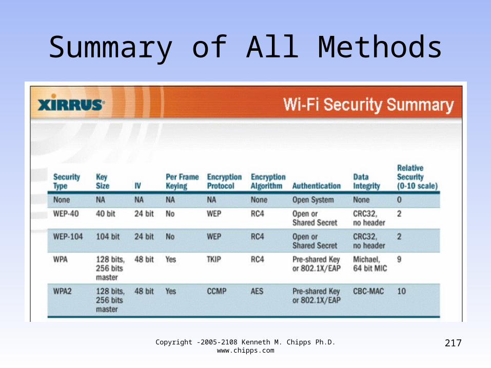
Summary of All Methods
Copyright -2005-2108 Kenneth M. Chipps Ph.D. www.chipps.com
217
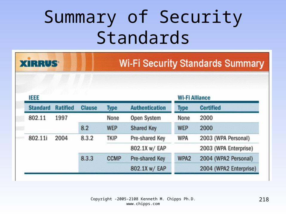
Summary of Security Standards
Copyright -2005-2108 Kenneth M. Chipps Ph.D. www.chipps.com
218