Embed Size (px)
Citation preview

Copyright © 1995, by the author(s).
All rights reserved.
Permission to make digital or hard copies of all or part of this work for personal or
classroom use is granted without fee provided that copies are not made or distributed
for profit or commercial advantage and that copies bear this notice and the full citation
on the first page. To copy otherwise, to republish, to post on servers or to redistribute to
lists, requires prior specific permission.

SURGICAL APPLICATIONS OF MILLI-ROBOTS
by
Michael B. Cohn, Lara S. Crawford, Jeffrey M. Wendlandt,and S. Shankar Sastry
Memorandum No. UCB/ERL M95/17
23 March 1995
SURGICAL APPLICATIONS OF MILLI-ROBOTS
by
Michael B. Cohn, Lara S. Crawford, Jeffrey M. Wendlandt,and S. Shankar Sastry
Memorandum No. UCB/ERL M95/17
23 March 1995
ELECTRONICS RESEARCH LABORATORY
College of EngineeringUniversity of California, Berkeley
94720
Surgical Applications of Milli-Robots. *
Michael B. CoW Lara S. Crawford** Jeffrey M. Wendlandt5S. Shankar Sastry*
University of California, Berkeley 94720
Abstract
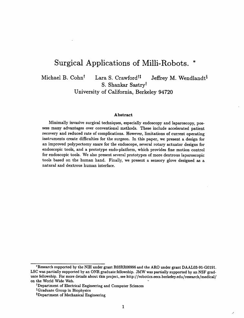
Minimally invasive surgical techniques, especially endoscopy and laparoscopy, possess many advantages over conventional methods. These include accelerated patientrecovery and reduced rate of complications. However, limitations of current operatinginstruments create difficulties for the surgeon. In this paper, we present a design foran improved polypectomy snare for the endoscope, several rotary actuator designs forendoscopic tools, and a prototype endo-platform, which provides fine motion controlfor endoscopic tools. We also present several prototypes of more dextrous laparoscopictools based on the human hand. Finally, we present a sensory glove designed as anatural and dextrous human interface.
"Research supported by the NIH under grant R03RR06996 and the ARO under grant DAAL03-91-G0191.LSCwaspartially supported by an ONRgraduate fellowship. JMW waspartially supported by an NSF graduate fellowship. For more details about this project, seehttp://robotics.eecs.berkeley.edu/research/medical/on the World Wide Web.
tDepartment of Electrical Engineering and Computer Sciences*Graduate Group in Biophysics^Department of Mechanical Engineering
1
List of Figures
1 Snare and forceps combination 62 Rotary screw actuator 73 Rotary pulley actuator 74 Flexible rotary-shaft actuator 85 Endo-platform 96 Endo-platform positioning biopsy forceps 107 Endo-platform and the tendon drivers 108 Controlled Step Response 119 Tracking a Circle at 2.0 Hz 1210 Laparoscopic manipulator fingers, constructed as molded rubber balloons. . . 1311 Hand-like end-effector 1412 Hydraulic end-effector with two degrees of freedom 1513 Schematic diagram of glove design 1814 Prototype glove device 1915 Finger-wearable tactile display constructed in the UC Berkeley Robotics Lab
oratory. 19
16 Diagram of pincing position used in calibration and movement tests 2017 Movement data for subject DM (first trial is solid trace, second trial is dashed
trace). Calibration data averages are shown as horizontal lines. For wrist:flat=solid, relaxed=dashed, flexed=dotted. For index and thumb: open=solid,relaxed=dashed, pincing=dotted. Horizontal axis is seconds and vertical axisis volts for each plot 22
18 Telesurgical workstation 2419 Design of telesurgical workstation slave module 24

List of Tables
Mean and standard deviation of calibration values for all subjects, in volts.Numbers in parentheses indicate total number of samples (both calibrationruns combined). Top figure is mean, bottom is standard deviation for eachsubject. *Only 35 values were recorded for the relaxed position for subject AC. 21
1 Introduction
Minimally invasive techniques, including endoscopic (gastrointestinal) and laparoscopic (abdominal) procedures, are revolutionizing the field of surgery. These techniques employ surgical instruments which are inserted into the body through a pre-existing orifice or a smallpuncture rather than the larger traditional incision. Minimally invasive procedures have several advantages over traditional surgery, the chief being minimization oftrauma to healthytissue. As a result, recovery is accelerated and the risk of complications from infection andscar adhesion is reduced. These considerations have motivated the application ofminimallyinvasive alternatives wherever feasible. However, there are limitations to the operating instruments now used in these procedures which exact a price in surgical access, dexterity,efficiency, and in some cases safety. It is our goal to design improved instruments and human interfaces for endoscopy and laparoscopy. We further envision a teleoperative surgicalsystem which would combine the improved interface and tools for laparoscopy to enhancethe surgeon's control of the operation.
2 Minimally-Invasive Surgery
Nearly all minimally invasive procedures employ means for imaging the surgical site in realtime. These may be non-invasive, as with fluoroscopy, or invasive, using, for example, anoptical fiberscope. Such instruments, or "scopes," may be flexible, like endoscopes, which areemployed in the gastrointestinal tract. Modern endoscopes deliver images via a miniaturevideo camera (CCD) at the instrument tip. When the operative site is sufficiently accessible,a rigid scope may be used. The laparoscope, used in abdominal surgery, is a typical example.In this case, the image is focused by lenses in a rigid tube onto an eyepiece at the base of thescope, to which a camera is usually attached. In both endoscopy and laparoscopy, viewinglight is delivered to the operative site by fiber optics, and the surgeon views the site on anexternal CRT. There are several problems inherent in these methods of imaging as comparedto direct viewing, including loss of depth perception with the two-dimensional view of theoperative field, reduced angle of view, reduced resolution, and lack of ability to pan quicklythrough the scene ([1]; [2], p. 39, p. 85). Technology such as stereo scopes, which providea three-dimensional image, is being developed to address these problems; we, however, willfocus mainly on instruments and mechanical human interfaces for surgery.
2.1 Endoscopy
Extensive discussion of endoscopic techniques is found in Baillie [3], Siegel [4], and Sil-verstein and Tytgat [5]. The main piece of equipment is the endoscope, a flexible tuberanging in length from 70-180 cm., typically 11 mm in diameter. Video image controls,air/water/suction controls, position controls, an insertion channel for the tools, and connections to the light source are attached to the end of the scope which is held by the surgeon.The distal end contains a lens to focus an image onto the video chip, the output aperture forthe light source, the tool port, and the water/air ports. The left/right, up/down position ofthe end of the endoscope is controlled by deforming the last 10 cm. of the flexible tube in an
arc using two dials on the outer end of the scope. Surgery in the colon or in the esophagus isperformed by inserting various tools through the endoscope to the operation site. The typicaldiameter of the tool channel is 2.8 mm. Biopsy forceps, polypectomy snares, three-prongedgraspers, and cytology brushes (which resemble pipe cleaners) are some of the tools usedin endoscopic procedures. The tools used in endoscopy generally possess 1 internal degreeof freedom and can be slid in and out of the endoscope. The direction of the tool axis isdetermined by the viewing direction of the end of the endoscope.
The major limitations in endoscopy are the lack of dexterity in the tools and the lack offine motion control. For example, biopsies in the esophagus are difficult since the esophagealchannel is long and rigid and the biopsies must be performed at right angles to the tool channel. The surgeon must move the entire last 10 cm. of the endoscope to slightly reposition thetool, which is not only too large a scale for some tasks, but also moves the surrounding tissue,further complicating the task. Also, the twist angle about the tool axis is not controllablein current instruments since the tools are long and not torsionally stiff. In this paper, wepresent a design for a snare-forceps combination to provide greater control when removingpolyps from the colon. We also discuss several designs for providing endoscopic tools withrotational control. Additionally, we present a prototype of the endo-platform, a modificationof the endoscope which provides fine motion control of the tool.
2.2 Laparoscopy
Discussion of laparoscopic techniques can be found in Graber, et al. [2], Semm [6], andSaleh [7]. Laparoscopic surgery takes place in an approximately 20 x 20 x 20 cm. workspaceinside the patient created by pumping gas into the abdominal cavity. The laparoscopeand laparoscopic instruments enter the body via 5 - 12 mm. diameter cannulae insertedthrough puncture incisions in the abdominal wall. There are many instruments available foruse in laparoscopic procedures, including biopsy forceps, various types of graspers, scissors,electrocautery devices, staplers, needle holders, and suture loops for ligation. Instrumentshave four degrees of freedom in addition to their internal freedoms (for example, openingand closing a grasper). Most of the instruments' internal freedoms are operated via slidinglinkages. The rigidity of the laparoscopic instruments and the use ofmultiple abdominal sitesgives the surgeon more degrees of freedom with which to work than in endoscopic techniques.
There are several limitations of the laparoscopic instruments which make laparoscopymore awkward for the surgeon than traditional "open" surgery. For example, the fixedaccess point to the abdomen makes it impossible for instruments to reach all positions andorientations. Since the instruments are rigid and unarticulated, they cannot bend aroundobstacles, making some areas of the abdominal cavity difficult to reach from a given entrypoint. Also, since the instruments pivot about a fulcrum in the patient's abdominal wall,the instrument tip moves left when the surgeon moves the handle right, and forward whenthe surgeon moves it back. This type of control likely interferes with a number of reflexesinvolved in fine manipulation. The lack of dexterity when operating with these instrumentsmakes some tasks, like suturing and knot-tying inside the body cavity, especially difficult ([2],pp. 23-25; [6], p. 98). In addition, the instruments are single-purpose. In order to changefrom grasping to cutting, for example, one must switch from one instrument to another.In this paper, we present several prototype laparoscopic instruments designed for improved
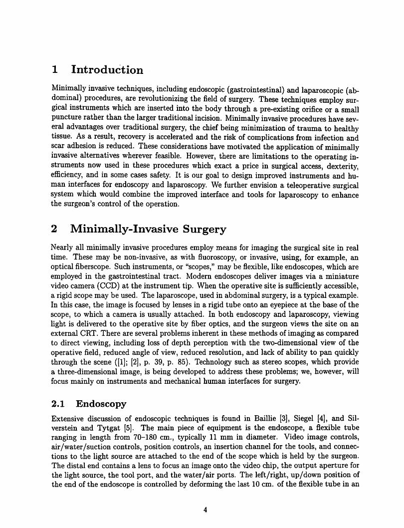
Figure 1: Snare and forceps combination.
dexterity and versatility. We also discuss a prototype glove designed as human interface tothese instruments.
3 Endoscopic Manipulators
3.1 Designs
This section describes several designs to provide additional dexterity and control in endoscopic instruments. We also present a prototype of one of the designs and experimentsperformed on this prototype.
Currently, polyps are severed by positioning a polypectomy snare over the polyp andtightening it as cautery current is applied. The polyp is then removed through the scope'ssuction channel. This process might be simplified with a combination of the snare and abiopsy forceps in which the forceps is positioned inside the snare opening (See Figure 1).The snare and forceps can move in and out relative to each other. With this devicer thebiopsy forceps can grasp the polyp and hold it while the snare is moved over the polyp andtightened. This is easier than trying to maneuver the snare around the polyp without theforceps to hold it steady. The forceps can then keep the polyp away from the wall of thecolon while cauterization is applied through the snare, so the current is concentrated at thebase of the polyp and cannot diffuse out of the polyp through contact with the colon walls.The severed polyp can be retrieved bysimply bringing it into the instrument/suction channelwith the forceps.
We have several concept designs to provide rotary motion about the tool's axis, althoughnone have been prototyped at this time. The first design uses a high pitch screw in a fixedhousing attached to a small piston such as those described in [8]; see Figure 2. As thepiston pushes or pulls the screw through the housing, the tool rotates. The bellows sealthe tool channel and permits its expansion. The housing of the tool needs to be secured tothe operating part of the tool. In current snares, for example, the housing is a plastic tubewhich is not fixed to the wire snare, but can be made to be rotationally fixed through designmodifications.
The second design for rotational motion is composed of a central pulley and two smallerpulleys driven by tendons. The central pulley is secured-to the tool. As the tendons arepulled, the central pulley spins in the fixed housing, rotating the tool. This design is shownin Figure 3.

Figure 2: Rotary screw actuator.
bousing
secures
tool
suiinert
!<one tendon . J 4 ^5 small
on upper
ring & onepulley
on lower \i
centra]
pulley
SIDE VIEW
tendon
TOP VIEW
Figure 3: Rotary pulley actuator.

Figure 4: Flexible rotary-shaft actuator.
The third design, shown in Figure 4, uses a flexible shaft to transform linear motion alongan axis to rotation about the same axis. The tool is secured in a central tool chuck with an
O-ring. Pulling the tendons rotates a pulley attached to the flexible shaft, which causes theshaft to rotate as well. The shaft bends through ninety degrees and transmits its rotationto a cylinder attached to its other end. This cylinder spins the chuck, causing the tool torotate.
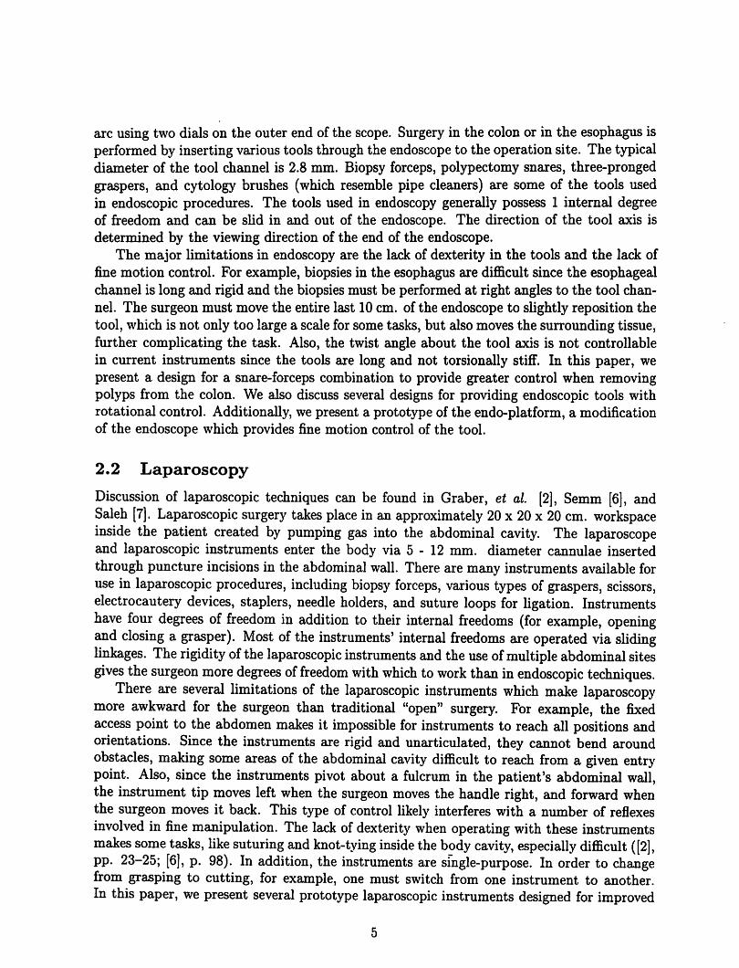
As mentioned above, the surgeon can only reposition the tool by bending the last 10 cm.of the endoscope or by sliding the tool in and out of the tool channel. Sometimes the toolcan also be repositioned by moving the patient and pushing on the patient's abdomen. Wehave designed a device, the endo-platform (see Figure 5), which allows more precise toolpositioning and will allow the surgeon to reorient the tool without moving the surroundingtissue. The platform is composed of two plates separated by a rigid tube and a shortspring, through which the tool passes. The diameter of the plates is the same as that of theendoscope. The spring serves as a spherical joint which resists side forces and provides apivot point. Three tendons running between the plates can be pulled individually to changethe orientationof the outer plate relative to the inner plate and move the tool tip. Any linearactuators that meet the force and space requirements can be substituted for the tendons,however. The lens and the CCD array are attached to the outer plate so that the view fieldmoves along with the tool. The water channels are extended flexibly between the platesto accommodate the motion. The entire assembly is designed to be attached to the end ofan existing endoscope. Large motions can be controlled as before by deforming the last 10cm. of the scope, while fine motions are accomplished by reorienting the outer plate of theendo-platform.
We plan to use a joystick as the user interface for the_endo-platform. The joystick willbe located at the base of the tool channel, and the tool will be inserted through its center.The endo-platform can also be combined with one of the rotary actuators described above
lifthu. kiu. and
other devices
crkVitcrpe
Figure 5: Endo-platform.
to further increase the tool's dexterity. The rotary actuator can then be controlled by a dialattached to the tip of the joystick which rotates about the joystick axis.
3.2 Prototype
We have constructed a prototype of the endo-platform (see Figures 6 and 7) and havedemonstrated the device's ability to
position endoscopic tools. The diameter of the plates is 19 mm. (but could easily bescaled to 11mm.), and the length of the device is less than 20 mm. from plate to plate. Thethree tendons are attached to pulleys on DC servomotors with optical position encoders.The endo-platform is capable of 90 degree deflection in any direction. The kinematics anddynamics of the device and a simulation of a closed-loop controller are described in detail in[9] and [10]. We have implemented a closed loop controller with an update rate of 500 Hzto position the endoscopic tools; our experimental results are described below.
Initially, we used 0.16 mm. stainless steel tendons, which resist tensile forces up to 12Newtons (N). With the tool at a 45 degree angle and a single motor pulling at 1.7 N, a 0.6N force was produced at the tool tip 11 mm. from the end of the endo-platform. Thus, atthe tensile strength of the metal tendons, a 4.2 N force could be produced. We are currentlyusing Kevlar tendons since 0.1 mm. Kevlar tendons have a tensile strength of 37 N and aremore durable than the metal tendons. At the tensile strength of the Kevlar tendons, a 13 Nforce is produced at the tool tip.
To test the dynamic response of the controlled endo-platform, we commanded the toolto point at an approximately 40 degree angle from the home configuration and recorded theposition response. The position response of the tool coordinates is shown in Figure 8. Thetool coordinates specify the pointing direction of the tool in terms of modified stereographicprojection coordinates. The final pointing angle is approximately 39 degrees. The solid lines
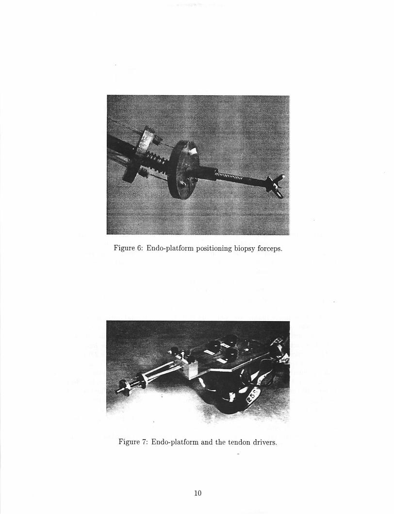
Figure 6: Endo-platform positioning biopsy forceps.
Figure 7: Endo-platform and the tendon drivers.
10
0.25
u
.
V
•1 / / simulation
• desired
•:// -
gamma
0.05 0.15iitne(s)
0.2 0.25
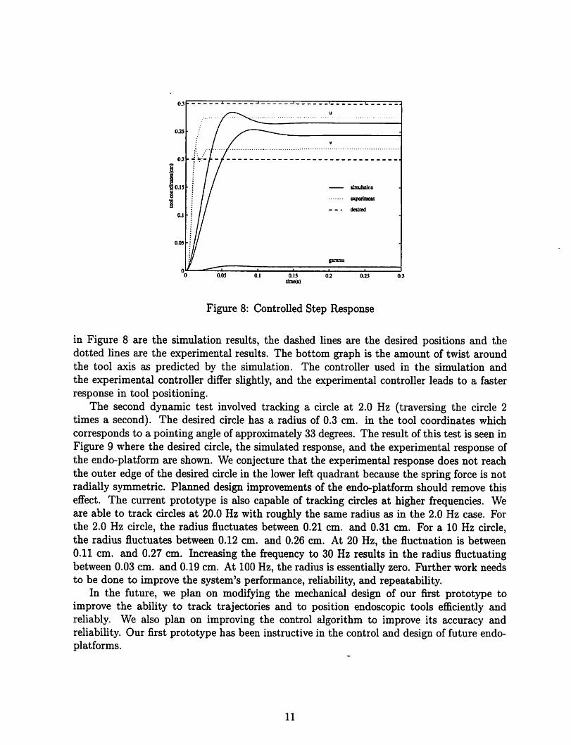
Figure 8: Controlled Step Response
in Figure 8 are the simulation results, the dashed lines are the desired positions and thedotted lines are the experimental results. The bottom graph is the amount of twist aroundthe tool axis as predicted by the simulation. The controller used in the simulation andthe experimental controller differ slightly, and the experimental controller leads to a fasterresponse in tool positioning.
The second dynamic test involved tracking a circle at 2.0 Hz (traversing the circle 2times a second). The desired circle has a radius of 0.3 cm. in the tool coordinates whichcorresponds to a pointing angle of approximately 33 degrees. The result of this test is seen inFigure 9 where the desired circle, the simulated response, and the experimental response ofthe endo-platform are shown. We conjecture that the experimental response does not reachthe outer edge of the desired circle in the lower left quadrant because the spring force is notradially symmetric. Planned design improvements of the endo-platform should remove thiseffect. The current prototype is also capable of tracking circles at higher frequencies. Weare able to track circles at 20.0 Hz with roughly the same radius as in the 2.0 Hz case. Forthe 2.0 Hz circle, the radius fluctuates between 0.21 cm. and 0.31 cm. For a 10 Hz circle,the radius fluctuates between 0.12 cm. and 0.26 cm. At 20 Hz, the fluctuation is between0.11 cm. and 0.27 cm. Increasing the frequency to 30 Hz results in the radius fluctuatingbetween 0.03 cm. and 0.19 cm. At 100 Hz, the radius is essentially zero. Further work needsto be done to improve the system's performance, reliability, and repeatability.
In the future, we plan on modifying the mechanical design of our first prototype toimprove the ability to track trajectories and to position endoscopic tools efficiently andreliably. We also plan on improving the control algorithm to improve its accuracy andreliability. Our first prototype has been instructive in the control and design of future endo-platforms.
11

0.2
£ o
-
•
jf^'^w\\
•
I % \
I isimulation
I
+++♦
experimeoi
desired
•
%v ••••'''']$ '
-
1 1 i "• «• —-0.4 0
u(cm)OJ
Figure 9: Tracking a Circle at 2.0 Hz
4 Laparoscopic Manipulators
4.1 Design Goals and Prototypes
As mentioned, there are several limitations to current laparoscopic manipulators, and anyattempt to address these must meet certain engineering constraints. Devices in current useare able to pass through a 5 - 12 mm. diameter cannula; general-purpose graspers andneedle-holders are able to transmit forces of approximately 10 N in any direction, basedon force measurements in generic grasping tasks. In addition, in a new instrument, a peakvelocity of 20 cm/s would be desirable, based on an estimate of human hand velocities insimilar tasks. Finally, a frequency response of 10 - 20 Hz is a useful minimum, based on therange of human hand bandwidth (see section 5.1 below). We have focused on the problemofsuturing, as well as the need for a more versatile tool to replace the single-purpose deviceswhich have evolved for specific surgical tasks. We have proceeded under the assumptionthat significant advances would call for new actuator technology to meet both size and costconstraints.
Initially, we envisioned a many-degree-of-freedom end-effector (robot hand) as a laparoscopic instrument. Such an instrument, based on the human hand, would allow extremelydextrous manipulation. One question was whether any practical improvement over the available one- or two-axis instruments was feasible, given the need to assemble the numeroussmall parts that would compose a millimeter-scale manipulator. As a result, we directedour efforts toward integrated fabrication approaches characteristic of the IC manufacturingprocess. Such an approach would potentially eliminate most of the assembly steps.
Our first-cut design was for a roughly anthropomorphic hand fitting in a 10 mm. diameter, 25 mm. long cylinder. Each finger was comprised of an elongated balloon, ribbed toallow expansion only on the dorsal surface and in a longitudinal direction (see Figure 10). Inthis way, inflatingthe finger with aircaused it to curl. The design wasinspired by the flexible
12
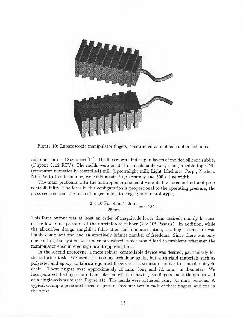
Figure 10: Laparoscopic manipulator fingers, constructed as molded rubber balloons.
micro-actuator of Suzumori [11]. The fingers were built up in layersof molded silicone rubber(Dupont 3112 RTV). The molds were created in machinable wax, using a table-top CNC(computer numerically controlled) mill (Spectralight mill, Light Machines Corp., Nashua,NH). With this technique, we could attain 50 fi accuracy and 500 [i line width.
The main problems with the anthropomorphic hand were its low force output and poorcontrollability. The force in this configuration is proportional to the operating pressure, thecross-section, and the ratio of finger radius to length; in our prototype,
2 x 10r,Pa -8mm2-2mm
25mm= 0.13N.
This force output was at least an order of magnitude lower than desired, mainly becauseof the low burst pressure of the unreinforced rubber (2 x 10⁵ Pascals). In addition, whilethe all-rubber design simplified fabrication and miniaturization, the finger structure washighly compliant and had an effectively infinite number of freedoms. Since there was onlyone control, the system was underconstrained, which would lead to problems whenever themanipulator encountered significant opposing forces.
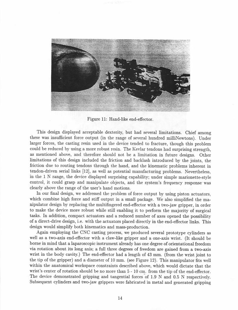
In the second prototype, a more robust, controllable device was desired, particularly forthe suturing task. We used the molding technique again, but with rigid materials such aspolyester and epoxy, to fabricate jointed fingers with a structure similar to that of a bicyclechain. These fingers were approximately 10 mm. long and 2.5 mm. in diameter. Weincorporated the fingers into hand-like end-effectors having two fingers and a thumb, as wellas a single-axis wrist (see Figure 11). The hands were actuated using 0.1 mm. tendons. Atypical example possessed seven degrees of freedom: two in each of three fingers, and one inthe wrist.
13
;::.—-?• ~t
Figure 11: Hand-like end-effector.
This design displayed acceptable dexterity, but had several limitations. Chief amongthese was insufficient force output (in the range of several hundred milliNewtons). Underlarger forces, the casting resin used in the device tended to fracture, though this problemcould be reduced by using a more robust resin. The Kevlar tendons had surprising strength,as mentioned above, and therefore should not be a limitation in future designs. Otherlimitations of this design included the friction and backlash introduced by the joints, thefriction due to routing tendons through the hand, and the kinematic problems inherent intendon-driven serial links [12], as well as potential manufacturing problems. Nevertheless,in the 1 N range, the device displayed surprising capability; under simple marionette-stylecontrol, it could grasp and manipulate objects, and the system's frequency response wasclearly above the range of the user's hand motions.
In our final design, we addressed the problem of force output by using piston actuators,which combine high force and stiff output in a small package. We also simplified the manipulator design by replacing the multifingered end-effector with a two-jaw gripper, in orderto make the device more robust while still enabling it to perform the majority of surgicaltasks. In addition, compact actuators and a reduced number of axes opened the possibilityof a direct-drive design, i.e. with the actuators placed directly in the end-effector links. Thisdesign would simplify both kinematics and mass-production.
Again employing the CNC casting process, we produced several prototype cylinders aswell as a two-axis end-effector with a claw-like gripper and a one-axis wrist. (It should beborne in mind that a laparoscopic instrument already has one degree of orientational freedomvia rotation about its long axis; a full three degrees of freedom are gained from a two-axiswrist in the body cavity.) The end-effector had a length of 43 mm. (from the wrist joint tothe tip of the gripper) and a diameter of 10 mm. (see Figure 12). This manipulator fits wellwithin the anatomical workspace constraints described above, which would dictate that thewrist's center of rotation should be no more than 5-10 cm. from the tip of the end-effector.The device demonstrated gripping and tangential forces of 1.9 N and 0.5 N respectively.Subsequent cylinders and two-jaw grippers were fabricated in metal and generated gripping
14

Figure 12: Hydraulic end-effector with two degrees of freedom.
forces in excess of 3 N.
Though there were several initial difficulties with this approach - such as creating reliableconnectors - it seems favorable for millimeter-scale surgical manipulators since large forcescan be generated. Force output is proportional to operating pressure, and the fundamentallimit on this quantity is the tensile strength of the structural materials.
4.2 Future Work
Future work will focus on implementation of a two-axis wrist, as well as position, tactile,and force feedback. Dimensional analysis of the generic piston actuator indicates that awrist fitting within the 10 mm. diameter constraint could generate adequate torques. Forcefeedback could assist in suture and knot tensioning as well as guard against inadvertentlaceration of tissue outside of the scope's field of view. Tactile sensing might be useful formanipulating suture material or other objects held in the gripper, localizing small anatomicalfeatures such as subsurface blood vessels, or detecting features which are obscured from thevideo camera. We hope to implement tactile feedback using strain sensor arrays on theend-effector coupled to stimulator arrays worn on the surgeon's fingertips. A "teletaction"system has recently been demonstrated [13] and tactile sensors spanning the 1 mm. to 3 cm.size range are being developed in our laboratory. The tactile sensors have a resolution of64 to 128 elements and employ capacitive sensing [14], [15]. The stimulator is a 25 element(5 x 5) array of air pistons spanning a 1 cm. square area. This system allows tactile featuresto be localized with 100 /i accuracy.
One possible ramification of capacitive tactile sensing would be permittivity sensing (theelectrostatic equivalent of metal detection). With a simple modification, a capacitive tactile
15

sensor element could be made insensitive to applied stress, in which case it would respondonly to the varying dielectric properties of its environment. Water has a particularly highdielectric constant of about 80, making most tissue easily detectable. Fatty tissue, composedmainly of non-polar molecules, would be have a lower dielectric constant. Blood vesselsshould be particularlydistinguishable, and cancerous tissue, with its increased water content,might be as well. (See [16], [17], [18] for the dielectric properties of tissues and cells.)
5 Human Interface
5.1 Design Issues
In designing the human interface for a teleoperative task, there are many issues to consider,some of which have already been mentioned above. Analyses of these issues can be foundin Brooks [19], Brooks and Bejczy [20], Burdea and Zhuang [21], Fischer, Daniel, and Siva[22], McAffee and Fiorini [23], and Sheridan [24]. One of the first questions is whethera non-dextrous controller will suffice for the specific teleoperative system. These devicesrange in complexity from knobs, joysticks, and teach pendants to universal 6-degree-of-freedom force-reflecting hand controllers (see [23], [20], [25], [22], [26], [27]). For systemswith many degrees of freedom or highly anthropomorphic slaves, however, a dextrous mastermay be required. A dextrous master is an anthropomorphic sensing device worn by theoperator to take advantage of the many degrees of freedom (twenty without the wrist [21])and natural dexterity of the human hand. One commercially available dextrous master thathas been popular for teleoperation applications is the VPL DataGlove™, which uses flexibleoptical fibers on the back of a glove to sense the amount of bending of the finger joints; themore a joint flexes, the less light is transmitted through the optical fiber (see [28]). TheDataGlove measures fourteen degrees offreedom on the hand (see [24], [29], [30]). A secondcommercially available dextrous master is the Exos Dextrous Hand Master™ (DHM). TheDHM is an exoskeleton that attaches to the joints of the hand and uses Hall-effect sensors tomeasure joint angles. It measures a total of sixteen degrees of freedom ([31], [28], [24], [30]).Another commercially available dextrous master is Virtual Technologies' CyberGlove™,which uses resistive sensors to measure joint angles. The standard CyberGlove measureseighteen degrees of freedom including wrist pitch and yaw. An augmented version of theCyberGlove measures twenty-two degrees offreedom [32]. All ofthesemasterscan be coupledwith a Polhemus or other global sensor to give the position and orientation of the whole hand.
One requirement that is often mentioned for a human interface is that it should makea system "transparent," or that it should allow the operator to feel telepresence. Thereare two issues that strongly influence the transparency of the system: the stimulus-responsecompatibility of the controller, and the amount and quality of feedback to the controller.Stimulus-response compatibility is a natural correspondence between the movements of theoperator and the movements of the manipulator; for example, when an operator movesa joystick left, he or she expects the manipulator to move left as well, in some intuitiveframe of reference. For a dextrous master, good stimulus-response compatibility may requirecomplex calibrations to accurately map the operator's joint movements to the manipulator'sjoint movements and discriminate between different human grasps. Readings from the VPL
16

DataGlove sensors, for example, do not correspond directly to the joint angles of the handand may be extensively correlated with each other (see [29]; [30]; [24]).
Force feedback enhances telepresence by presenting information about the magnitude ofcontact forces in a natural way, while tactile feedback presents information about textureand vibration. The importance of force feedback has been stressed by many authors ([33],[25], [21], [34], [24]), and studies have shown that teleoperative tasks are completed faster ormore accurately when the operator has force feedback available ([35], [36], [37], [24], [34]).Although there are many non-dextrous controllers available with force feedback, and havebeen for many years (see [20], [35], [36], [23], [25], [34], [24]) dextrous controllers with forcefeedback are still an area of ongoing research. None of the commercially available dextrousmasters of which we are aware has force feedback. Various prototypes exist, however, andseveral are discussed by Burdea and Zhuang in [38]. Tactile feedback is even less developed;tactile sensing and display systems are currently bulky and difficult to implement (see [13],[14], [37]). Other factors influencing the feel of a teleoperative interface are the impedance,loop gains, and informational bandwidth of the master-slave system. A discussion of thehuman-machine impedance and factors affectingthe perceived force feedback can be found inBurdea and Zhuang ([21]). Discussions of impedance, damping, and inertia in teleoperativesystems can be found in [21], [24], and [22]. Fischer, et al. [22], also address gain ratiosand velocity, acceleration, and force maxima. According to Brooks ([19]), the human handcan output information at a maximum rate of 5-10 Hz (1-2 Hz for unexpected signals, 2-5Hz for periodic signals, about 5 Hz for "internally generated or learned trajectories," andabout 10 Hz for reflexes). It can receive information at 20 to 30 Hz for force (kinesthetic)and position feedback and up to about 320 Hz for tactile feedback. Different authors havediffering views on what bandwidth is needed for teleoperation, however (see [34], [22], e.g.).Brooks' survey of teleoperator experts obtained a minimum required bandwidth of 3.9 Hzand preferred bandwidth of 9.7 Hz ([19]).
Finally, the operator's safety, comfort, fatigue level, and ability to use the controller witha single hand, as well as the cost of the device, areall important issues in designing a humaninterface.
5.2 Prototype
For the endo-platform device, a simple, nondextrous master such as a joystick is sufficient fornatural control. The laparoscopic manipulator, however, is more complex and may requirea more complex, dextrous human interface. The commercially available dextrous mastersare not ideal because they are quite expensive and have many more degrees of freedom thanwe need for controlling the prototype robotic hand. Based on the considerations above,we have designed and built a prototype human interface for the laparoscopic telesurgicalsystem. We decided on a glove-likedextrous master. For a telesurgical application, this kindof anthropomorphic dextrous controller is particularly appropriate, since the surgeon hasa high degree of manual dexterity and is experienced with hand-held tools. The glove-likedevice will also have good stimulus-response compatibility with an articulated robot hand.The current human interface in laparoscopy lacks this compatibility, as mentioned in section2.2. The prototype glove does not incorporate force feedback at this time.
The glove senses thumb and index finger flexion, wrist flexion, and wrist rotation. It thus
17
Optical sensor
Res.stive flexion sensor
Gray scale
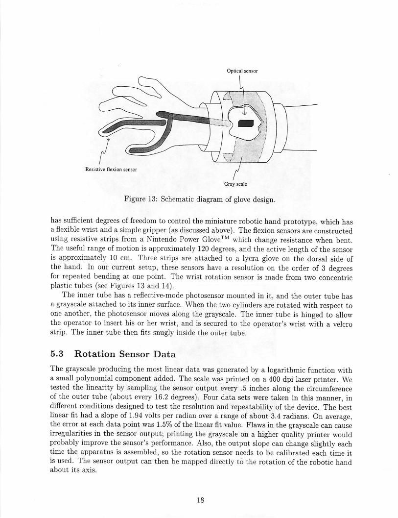
Figure 13: Schematic diagram of glove design.
has sufficient degrees of freedom to control the miniature robotic hand prototype, which hasa flexible wrist and a simple gripper (as discussed above). The flexion sensors are constructedusing resistive strips from a Nintendo Power Glove™ which change resistance when bent.The useful range ofmotion is approximately 120 degrees, and the active length of the sensoris approximately 10 cm. Three strips are attached to a lycra glove on the dorsal side ofthe hand. In our current setup, these sensors have a resolution on the order of 3 degreesfor repeated bending at one point. The wrist rotation sensor is made from two concentricplastic tubes (see Figures 13 and 14).
The inner tube has a reflective-mode photosensor mounted in it, and the outer tube hasa grayscale attached to its inner surface. When the two cylinders are rotated with respect toone another, the photosensor moves along the grayscale. The inner tube is hinged to allowthe operator to insert his or her wrist, and is secured to the operator's wrist with a velcrostrip. The inner tube then fits snugly inside the outer tube.
5.3 Rotation Sensor Data
The grayscale producing the most linear data was generated by a logarithmic function witha small polynomial component added. The scale was printed on a 400 dpi laser printer. Wetested the linearity by sampling the sensor output every .5 inches along the circumferenceof the outer tube (about every 16.2 degrees). Four data sets were taken in this manner, indifferent conditions designed to test the resolution and repeatability of the device. The bestlinear fit had a slope of 1.94 volts per radian over a range ofabout 3.4 radians. On average,the error at each data point was 1.5% of the linear fit value. Flawsin the grayscale can causeirregularities in the sensor output; printing the grayscale on a higher quality printer wouldprobably improve the sensor's performance. Also, the output slope can change slightly eachtime the apparatus is assembled, so the rotation sensor needs to be calibrated each time itis used. The sensor output can then be mapped directly to the rotation of the robotic handabout its axis.
18

Figure 14: Prototype glove device.
Figure 15: Finger-wearable tactile display constructed in the UC Berkeley Robotics Laboratory.
19
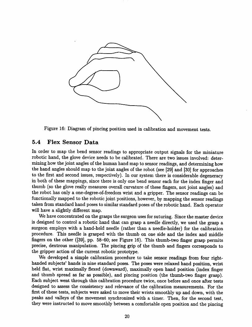
Figure 16: Diagram of pincing position used in calibration and movement tests.
5.4 Flex Sensor Data
In order to map the bend sensor readings to appropriate output signals for the miniaturerobotic hand, the glove device needs to be calibrated. There are two issues involved: determininghowthe joint angles of the human hand map to sensor readings, and determining howthe hand angles should map to the joint angles of the robot (see [29] and [30] for approachesto the first and second issues, respectively). In our system there is considerable degeneracyin both of these mappings, since there is only one bend sensor each for the index finger andthumb (so the glove really measures overall curvature of these fingers, not joint angles) andthe robot has only a one-degree-of-freedom wrist and a gripper. The sensor readings can befunctionally mapped to the robotic joint positions, however, by mapping the sensor readingstaken from standard hand poses to similar standard poses of the robotic hand. Each operatorwill have a slightly different map.
We have concentrated on the grasps the surgeon uses for suturing. Since the master deviceis designed to control a robotic hand that can grasp a needle directly, we used the grasp asurgeon employs with a hand-held needle (rather than a needle-holder) for the calibrationprocedure. This needle is grasped with the thumb on one side and the index and middlefingers on the other ([39], pp. 58-60; see Figure 16). This thumb-two finger grasp permitsprecise, dextrous manipulation. The pincing grip of the thumb and fingers corresponds tothe gripper action of the current robotic prototype.
We developed a simple calibration procedure to take sensor readings from four right-handed subjects' hands in nine standard poses. The poses were relaxed hand position, wristheld flat, wrist maximally flexed (downward), maximally open hand position (index fingerand thumb spread as far as possible), and pincing position (the thumb-two finger grasp).Each subject went through this calibration procedure twice, once before and once after testsdesigned to assess the consistency and relevance of the calibration measurements. For thefirst of these tests, subjects were asked to move their wrists smoothly up and down, with thepeaks and valleys of the movement synchronized with a timer. Then, for the second test,they were instructed to move smoothly between a comfortable open position and the pincing
20
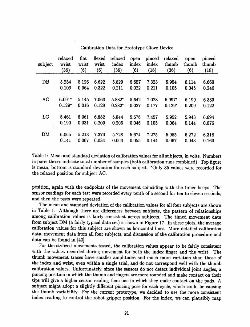
Calibration Data for Prototype Glove Device
relaxed flat flexed relaxed open pinced relaxed open pincedsubject wrist wrist wrist index index index thumb thumb thumb
(36) (6) (6) (36) (6) (18) (36) (6) (18)
DB 5.254 5.126 6.622 5.829 5.657 7.323 5.954 6.114 6.669
0.109 0.064 0.322 0.211 0.022 0.211 0.105 0.045 0.246
AC 6.091* 5.145 7.063 5.882* 5.642 7.028 5.997* 6.199 6.333
0.129* 0.016 0.129 0.282* 0.027 0.177 0.129* 0.209 0.122
LC 5.461 5.061 6.882 5.844 5.676 7.457 5.952 5.943 6.694
0.190 0.031 0.209 0.206 0.046 0.105 0.064 0.144 0.076
DM 6.065 5.213 7.370 5.728 5.674 7.275 5.955 6.272 6.318
0.141 0.067 0.034 0.063 0.055 0.144 0.067 0.043 0.160
Table 1: Mean and standard deviation of calibration values for all subjects, in volts. Numbersin parentheses indicate total number of samples (both calibrationruns combined). Top figureis mean, bottom is standard deviation for each subject. *Only 35 values were recorded forthe relaxed position for subject AC.
position, again with the endpoints of the movement coinciding with the timer beeps. Thesensor readings for each test were recorded every tenth of a second for ten to eleven seconds,and then the tests were repeated.
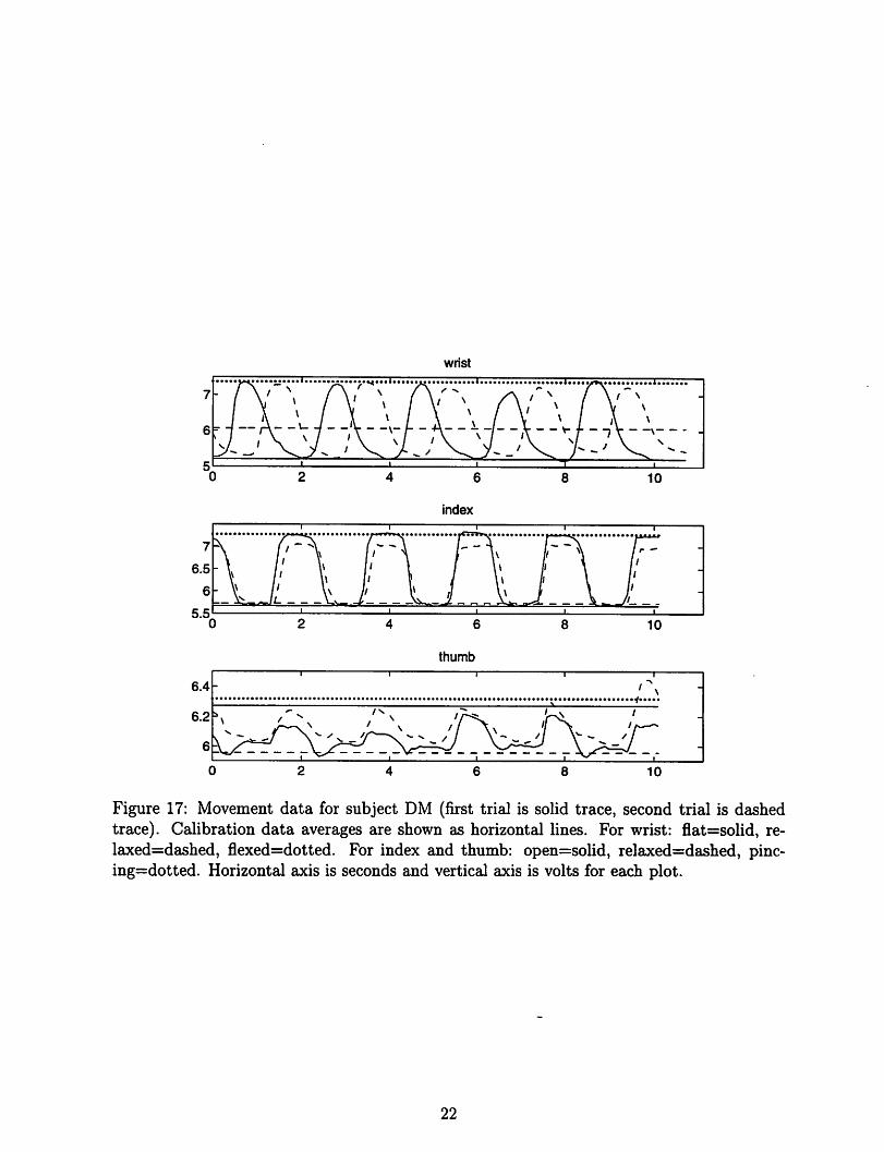
The mean and standard deviation of the calibrationvalues for all four subjects are shownin Table 1. Although there are differences between subjects, the pattern of relationshipsamong calibration values is fairly consistent across subjects. The timed movement datafrom subject DM (a fairly typical data set) is shown in Figure 17. In these plots, the averagecalibration values for this subject are shown as horizontal lines. More detailed calibrationdata, movement data from all four subjects, and discussion of the calibration procedure anddata can be found in [40].
For the stylized movements tested, the calibration values appear to be fairly consistentwith the values recorded during movement for both the index finger and the wrist. Thethumb movement traces have smaller amplitudes and much more variation than those ofthe index and wrist, even within a single trial, and do not correspond well with the thumbcalibration values. Unfortunately, since the sensors do not detect individual joint angles, apincing position in which the thumb and fingers are more rounded and make contact on theirtips will give a higher sensor reading than one in which they make contact on the pads. Asubject might adopt a slightly different pincing pose for each cycle, which could be causingthe thumb variability. For the current prototype, we decided to use the more consistentindex reading to control the robot gripper position. For the index, we can plausibly map
21
wrist
index
thumb
6.4
1 • i i
>\ -
6.2
6
\
i _
' ^ -y—\*• ^^// \--/i \
/
/ /
1
10
Figure 17: Movement data for subject DM (first trial is solid trace, second trial is dashedtrace). Calibration data averages are shown as horizontal lines. For wrist: flat=solid, re-laxed=dashed, flexed=dotted. For index and thumb: open=solid, relaxed=dashed, pinc-ing=dotted. Horizontal axis is seconds and vertical axis is volts for each plot.
22
the open calibration value (and anything below it) to a fully open gripper and the pincingvalue (and anything above it) to a fully closed gripper. The intermediate values correspondto intermediate states of the gripper. A similar map can be used for the wrist. The subjectswere instructed not to bend their wrists upward past the flat position, since the wrist flexsensor tended to buckle when the wrist was bent upward, producing anomalous readings.
5.5 Future Work
The prototype glove has several advantages for use in telesurgery. It is simply constructed,it incorporates wrist rotation and flexion sensors, and it is lightweight and non-fatiguing. Itmakes use of the natural correspondence between thumb and index finger pincing and therobot's gripper action. Since the sensor signals can be mapped directly to desired positionsof the robot joints, very little computation is needed for position control of the slave, and thepreliminary data suggests that the glove will function well asa master for test suturing tasks.Many improvements can be made on this initial prototype, however. To more accuratelysense finger, and especially thumb, position, the glove should have separate flex sensors foreach joint. The glove should also incorporate a sensor to measure upward wrist flexionas well as downward. Future prototypes should have an improved physical design to easeputting on and removing the glove. The main drawback of this glove prototype, and indeedany glove, is the difficulty of incorporating force feedback. The lack of force feedback in theprototype has proven to be a disadvantage in test teleoperative tasks. The lack of a suitableactuator technology, however, makes incorporating force feedback into a glove difficult. Inthe future, we may sacrifice some dexterity by switching to a master device based on a moreconventional design, such as a Stewart platform, in order to make use of force feedback.Tactile feedback will be incorporated into future masters as well.
6 Telesurgical Workstation
As a step toward a teleoperative surgical workstation (see Figures 18 and 19), we haveinstalled the prototype robotic
manipulator and glove on a robotic platform. The platform can provide the manipulatorwith x, y, and z (vertical) positioning and rotation (0) about the z axis and can senseforce in the z and 6 axes. The x, y> z, and 9 control signals may be generated by a sensorattached to the glove or by simply using a second module of the platform as a master forthe global position. The wrist and gripper of the manipulator are controlled by the wristand finger readings of the glove, as described above. Preliminary open-loop tests (run at 10Hz) of the gripper and wrist controls have been promising. The glove has also been testedin simple teleoperative tasks (picking up a small object) with larger fingers equipped withtactile sensors that were developed in ourlaboratory (see [41]). The tactile display, mountedon the first finger of the glove, rendered the force image obtained by the tactile sensors,providing detailed grip force and object position information in real-time. The platformwill help to evaluate prototypes' effectiveness in laparoscopic tasks such as suturing, andwill help identify problems in designing a teleoperative workstation for use in the operatingroom. The mainhurdles we foresee include making the platform compact enough and simple
23

Figure 18: Telesurgical workstation.
Figure 19: Design of telesurgical workstation slave module.
24

enough to set up that it will not interfere with operating room procedure or access to thepatient in case of an emergency.
25

References
[1] F. Tendick, R. Jennings, G. Tharp, and L. Stark. Sensing and manipulation problemsin endoscopic surgery: Experiment, analysis, and observation. Presence, 2(1):66-81,winter 1993.
[2] J. N. Graber, L. S. Schultz, J. J. Pietrafitta, and D. F. Hickok. Laparoscopic AbdominalSurgery. McGraw-Hill, San Francisco, 1993.
[3] John Baillie. Gastrointestinal Endoscopy: Basic Principles and Practice. Butterworth-Heinemann, Oxford, 1992.
[4] Jerome H. Siegel. Endoscopic Retrograde Cholangiopancreatography: Technique, Diagnosis, and Therapy. Raven Press, New York, 1992.
[5] Fred E. Silverstein and Guido N.J. Tytgat. Atlas ofGastrointestinal Endoscopy. GowerMedical, New York, 1991.
[6] K. Semm. Operative Manual for Endoscopic Abdominal Surgery: Operative Pelviscopy,Operative Laparoscopy. Year Book Medical, Chicago, 1987.
[7] J. W. Saleh. Laparoscopy. Saunders, Philadelphia, 1988.
[8] M. Cohn, C. Deno, and J. Fuji. Hydraulic actuator, robot containing same, and methodof producing same. U.S. Patent Application, 1993.
[9] J. M. Wendlandt. Milli robotics for endoscopy. ERL technical report UCB/ERL M94/7,University of California at Berkeley, 1994. Department of EECS.
[10] J. M. Wendlandt and S. S. Sastry. Design and control of a simplified Stewart platformfor endoscopy. In IEEE 33rd Conference on Decision and Control, Lake Buena Vista,FL, December 1994.
[11] K. Suzumori, S. likura, and H. Tanaka. Development of flexible microactuator and itsapplication to robotic mechanisms. In IEEE International Conference on Robotics andAutomation, pages 1622-1627, Sacramento, CA, April 1991.
[12] C. Deno, R. Murray, K. Pister, and S. Sastry. Finger-like biomechanical robots. ERLTechnical Report, University of California at Berkeley, 1992. Department of EECS.
[13] M. Cohn, M. Lam, and R. S. Fearing. Tactile feedback for teleoperation. In Telema-nipulator Technology, SPIE Proc. 1833, pages 240-254, Boston, November 1992.
[14] R. S. Fearing. Tactile sensing mechanisms. International Journal ofRobotics Research,9(3):3-23, June 1990.
[15] B. Gray. Asurface-machined capacitive microtactile sensor. Research in progress, U.C.Berkeley, EECS Department, 1995.
26
[16] H. P. Schwan. Dielectric propertiesofcells and tissues. In A. Chiabrera, C. Nicolini, andH. P. Schwan, editors, Interactions Between Electromagnetic Fields and Cells. PlenumPress and NATO Scientific Affairs Division, New York, 1985.
[17] E. H. Grant, V. E. R. McLean, N. R. V. Nightingale, and C. Gabriel. Dielectric properties of water in biological solutions. In A. Chiabrera, C. Nicolini, and H. P. Schwan, editors, Interactions Between Electromagnetic Fields and Cells. Plenum Press and NATOScientific Affairs Division, New York, 1985.
[18] K. V. I. S. Kaler and T. B. Jones. Dielectrophoretic spectra of single cells determinedby feedback-controlled levitation. Biophysical Journal, 57:173-182, February 1990.
[19] T. L. Brooks. Telerobotic response requirement. In IEEE International Conference onSystems, Man and Cybernetics, pages 113-120, Los Angeles, Nov. 4-7 1990.
[20] T. L. Brooks and A. K. Bejczy. Hand controllers for teleoperation. JPL Publication85-11, JPL, March 1985.
[21] G. Burdea and J. C. Zhuang. Dextrous telerobotics with force feedback - an overview:1. human factors. Robotica, 9:171-178, April-June 1991.
[22] P. Fischer, R. Daniel, and K. V. Siva. Specification and design of input devices for teleoperation. In IEEE Conference on Robotics and Automation, pages 540-545, Cincinnati,1990.
[23] D. A. McAffee and P. Fiorini. Hand controller design requirements and performanceissues in telerobotics. In Fifth International Conference on Advanced Robotics, pages186-192, Pisa, Italy, 1991.
[24] T. B. Sheridan. Telerobotics, Automation, and Human Supervisory Control. MIT Press.Cambridge, MA, 1992.
[25] A. K. Bejczy and K. Salisbury. Controlling remote manipulators through kinestheticcoupling. Computers in Mechanical Engineering, 2:48-60, July 1983.
[26] V. Hayward, C. Nemri, X. Chen, and B. Duplat. Kinematic decoupling in mechanisms and application to a passive hand controller design. Journal of Robotic Systems,10(5):767-790, July 1993.
[27] K. V. Siva, A. A. Dumbreck, P. J. Fischer, and E. Abel. Development of a generalpurpose hand controller for advanced teleoperation. In International Symposium onTeleoperation and Control, pages 277-290, Bristol, England, 1988.
[28] H. Eglowstein. Reach out and touch your data. Byte, 15(7):283-290, July 1990.
[29] J. Hong and X. Tan. Calibrating a vpl dataglove for teleoperating the utah/mit hand.In IEEE Conference on Robotics and Automation, pages 1752-1757, Scottsdale, AZ,1989.
27
[30] L. Pao and T. H. Speeter. Transformation of human hand positions for robotic handcontrol. In IEEE Conference on Robotics andAutomation, pages 1758-1763, Scottsdale,AZ, 1989.
[31] B. A. Marcus, P. J. Churchill, and A. D. Little. Sensing human hand motions forcontrolling dexterous robots. In Lyndon B. Johnson Space Center 2nd Annual Workshopon Space Operations Automation and Robotics (SOAR), pages 481-485, 1988.
[32] Virtual Technologies, Palo Alto, CA. Price list, 1994.
[33] A. K. Bejczy. Sensors, controls, and man-machine interfaces for advanced teleoperation.Science, 208(4450):1327-1335, June 1980.
[34] J. E. E. Sharpe. Technical and human operational requirements for skill transfer inteleoperations. In International Symposium on Teleoperation and Control, pages 175-187, Bristol, England, 1988.
[35] J. W. Hill. Study to design and develop remote manipulator systems. NASA contractnas2-8652, NASA-CR-152092, SRI project 4055, JPL, July 1976.
[36] J. W. Hill. Study of modeling and evaluation of remote manipulation tasks with force-feedback. Technical report, JPL contract 95-5170, JPL, March 1979.
[37] R. D. Howe. Aforce-reflecting teleoperated hand system for the study oftactile sensingin precision manipulation. In IEEE International Conference on Robotics and Automation, pages 1321-1326, Nice, France, May 1992.
[38] G. Burdea and J. C. Zhuang. Dextrous telerobotics with force feedback - an overview:2. control and implementation. Robotica, 9:291-298, July-September 1991.
[39] R. M. Anderson and R. F. Romfh. Technique in the Use of Surgical Tools. Appleton-Century-Crofts, New York, 1980.
[40] L. S. Crawford. A dextrous master for telesurgery. ERL technical report UCB/ERLM93/95, University of California at Berkeley, 1993. Department of Electrical Engineering and Computer Science.
[41] E. J. Nicolson and R. S. Fearing. Sensing capabilities oflinear elastic cylindrical fingers.In IEEE/RSJ International Conference on Intelligent Robots and Systems, Yokohama,Japan, July 1993.
28