Embed Size (px)
Citation preview
p--.Ce)
INVESTIGATION OF PARAMETERS INFLUENCING THE DEFLECTION
OF A THICK WALL JET BY A THIN WALL JET COFLOWING
OVER A ROUNDED CORNER
by
Gregory G. Huson
APPROVED FOR PUBLIC RE'.EASE: DISTRIBUTION UNLIMITED
i-'. VI-'\ fi0.1,.j AND SUq ArCE EFFECTS DEPA r T;NFlT
DTNSFIDC/ASED-83/10
D;'ccmber 1983ELI .....
--St - Copy
84 02 I4

UNCLASSIFIED'ECUItlTY CLASSIFICATION OF THIS PAOE (When Date Entored)
REOR OCM UTO PG READ INS "RUCTIONS• REPORT DOCUM NTATION~ PAGE BEFORE COMPLETING FORM
I. REPORT NUMBER OV ACqEISN RECIPIENT'S CATALOG NUMBER
DTNSRDC/ASED-83/10
4. TITLE (and Subtitle) • TYPE or REPORT & PERIOD COVERED
INVESTIGATION OF PARAMETERS INFLUENCING THE Final Report
DEFLECTION OF A THICK WALL JET BY A THIN WALL January 81 - July 82
JET COFLOWING OVER A ROUNDED CORNER F. PERFORMING ORG. REPORT NUMBER
7. AUTHOR(&) S. CONTRACT OR GRANT NUMBERta)
Gregory G. Huson
1. PERFORMING ORGANIZATION NAME AND ADDRESS 10. PROGRAM ELEMENT, PROJECT, TASXAREA & WORV UNIT NUMBERS
David Taylor Naval Ship R&D Center Program Element 61152NAviation and Surface Effects Department Task Area ZR0230?01iBethesda, Maryland 20084 Work Unit 1660-610
I1. CONTROLLING OFFICE NAME AND ADDRESS 12. REPORT D.At
David Taylor Naval Ship R&D Center December 1983Aviation and Surface Effects Department 13. NUMBER OF PAGES
Bethesda, Maryland 20084 53S14. MONITORING AGENCY NAME & ADDRESS(ifdifferent It=m Control•t g Office) IS- SECURITY CLASS. (of this wpot)
UNCLASSIFIEDI$S. DECLASSIFICATIOIN/DOWNGRADING
SCHEDULE
16. DISTRIBUTION STATEMENT (oft ht.v Report)
APPROVED FOR PUBLIC RELEASE: DISTRIBUTION UNLIKITED
17. DISTRIBUTION STATEMENT (of the abstract entered In Bflock 20, It di fferent from Report)
I$. SUPPLEMENTARY NOTES
is, xiy WOnoS (Cognttnu* on toverso aide It neoeeee4f and Identify by black numbo)
Circulation ControlUpper Surface BlowingWall JetJet Deflection
110. A1*Z PACT fContinue on rev erse side it nece ssary a nd Identity by block numbe r) e ' i c l t o o t o--Recent investigations proved the compatibility of theCirculation Controland the Upper Surface Blowing concepts. This static investigation is afollow-up to determine what combinations of geometric and pneumatic variablesproduce an effective deflection of a thick wall jet by a thin wall jetexhausting over a rounded corner. Static pressure distributions over thecorner indicate that maximum deflections of the thick wall jet occur when ahigh average suction is distributed over the surface of the corner. Using alarge corner radius, locating the source of the thick wall jet somewhat ---
DDO I, JAN 1473 EOITION OF I NOV 61 $S OUOL•ET UNCLASSIFIED[I ~ ~~~~~~~~S/N 0,1O2.LF-014.601 ,t.v t ,cvo .v,.o - .II SE1CURITY CLAW PUCAVINOF o~THIS PAGE a ( O*A* 1W49004
UNCLASSIFIED
SECURITY CLASSIFICATION OF THIS PAGE (*bon Dota ,Enered)
Block 20 (continued)
upstream from the corner and the thin wall jet source, and using a highaspect ratio thick wall jet are geometric means of producing this typeof pressure distribution.
Accession ForNTIS GRA&IDTIC TABUnannounced QJustificatiort
Distribution/Availability Codes
JAvail and/orDist Special
Ma-!
UNCLASSIFIEDSECUOaVY CLAWFICATION 0"1419 0&6O(Mft DOeM aMmE
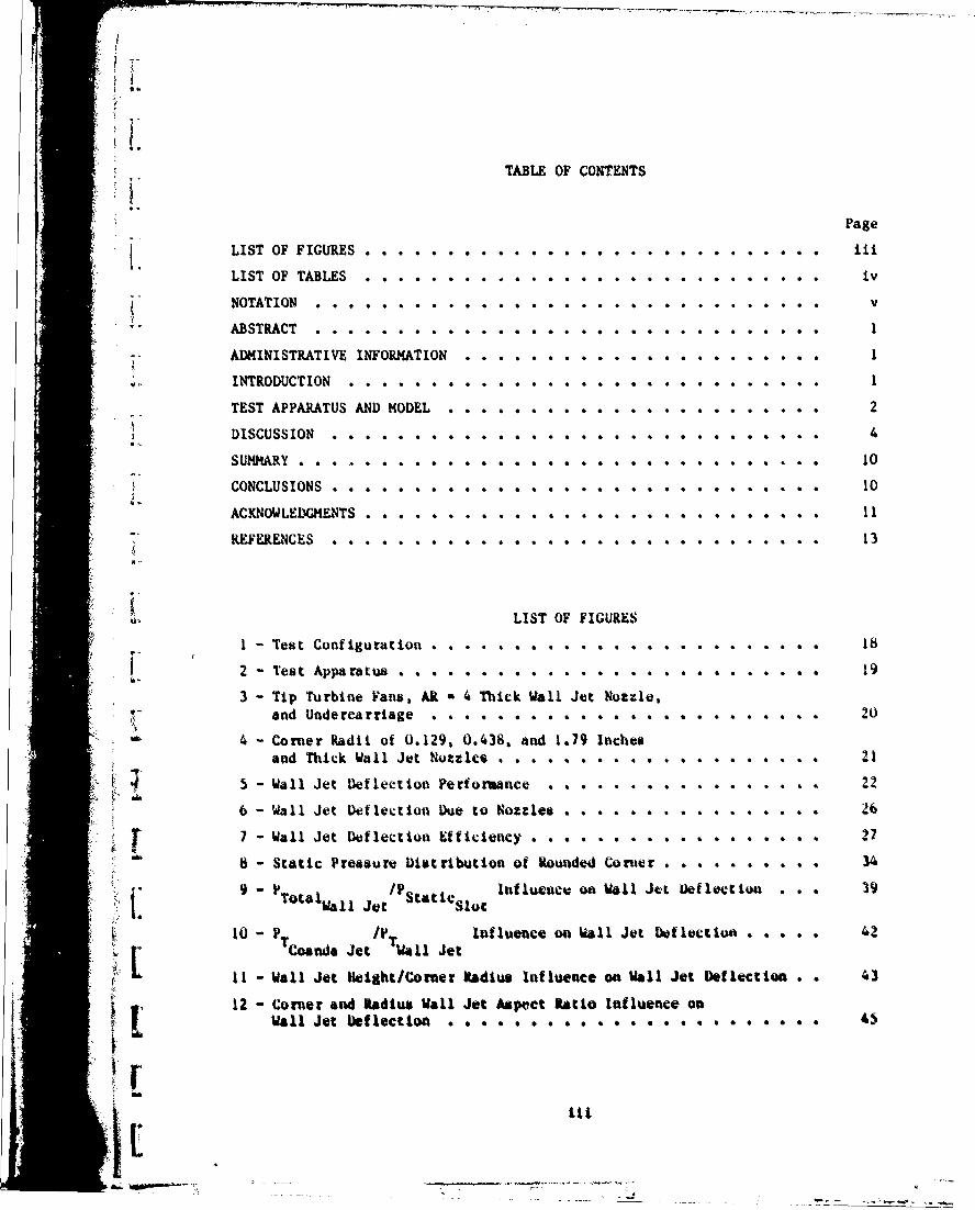
TABLE OF CONTENTS
Page
LIST OF FIGURES . . . . . . . . . . . . .. .. ... .
LIST OF TABLES . . . . . . . . . . . . . . . . . . . . . . . . . . . . ivi- NOTATION ... . . . . . . . . .. .. .. ... . v
ABSTRACT . . . . .1
ADMINISTRATIVE INFORMATION ...................... I.•INTRODUCTION .. .. .. .. .. ... .. . . .. ..... . 1
TEST APPARATUS AND MODEL ....................... 2
DISCUSSION . .. . . . . . . . . . . . . . . . . . . . 4
SUMM1ARY .. . . . ... . ..... .... .... . 10
I CONCLUSIONS . . . . . . . . . . . . . . . . . . ............ 10
ACKNOWLEDGMENTS . . . . . . . . . . . . . . . . . . . . . . . . . . . . 13"" REFERENCES .. .13
LIST OF FIGURES
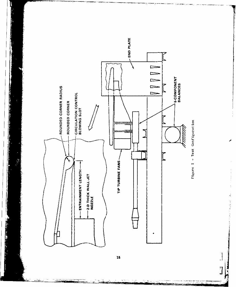
I - Test Configuration .................. ... . 18
2 - Test Apparatus . . . . . . . . . . . 19
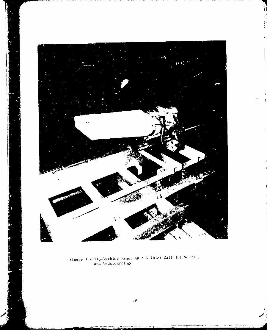
3 - Tip Turbine Fans, AR * 4 Thick Wall Jet Nozzle,"and Undercarriage .................. ... . 20
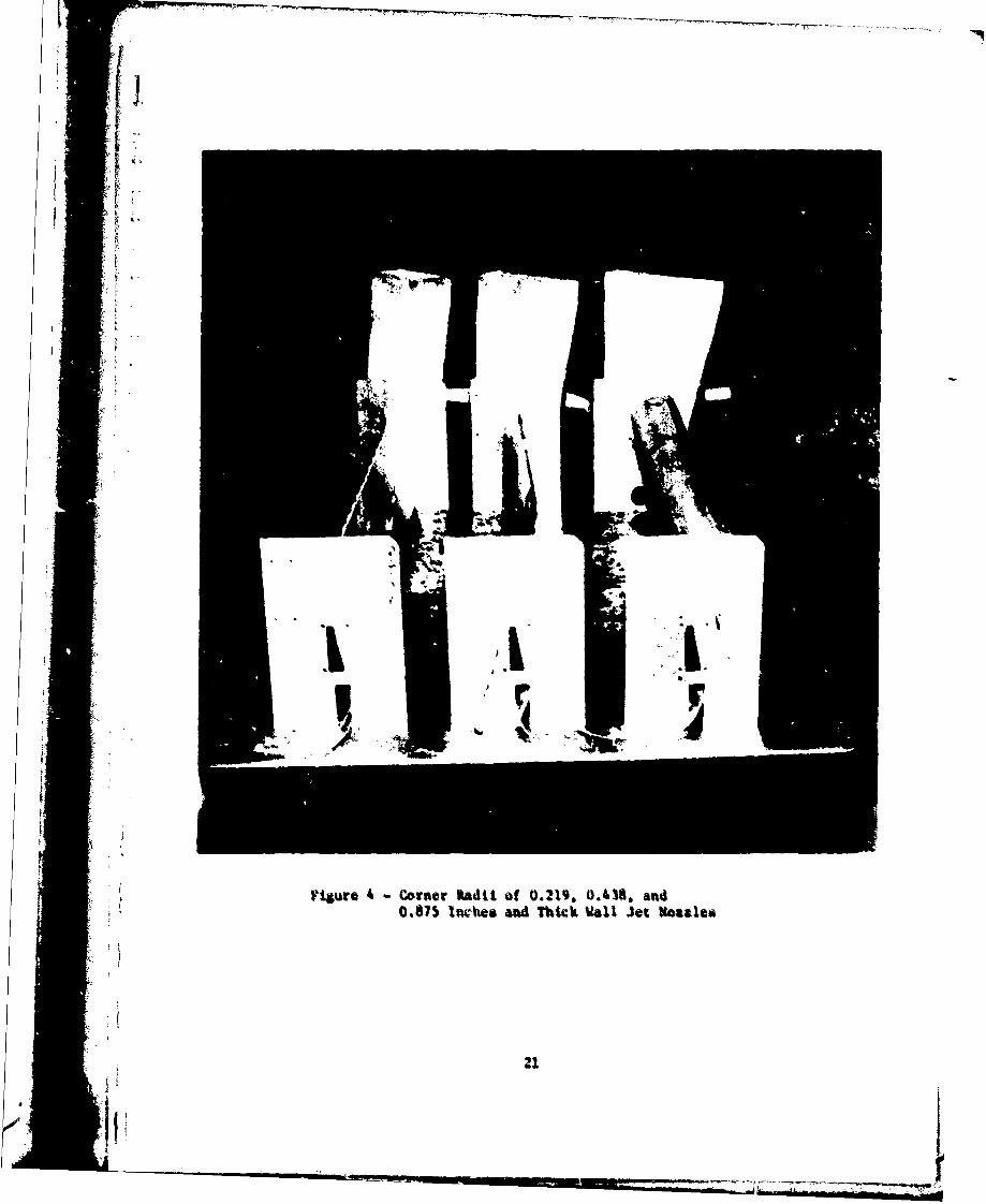
Nil-4 - Corner Radii of 0.129, 0.438, and 1.79 Inchesand Thick Wall Jet Nozzles ................. 21
4 5 - Wall Jet Defleetion Perforuance . . . . . ................. . . 22
6 -Wall Jet Deflection Due to Nozzles .......... ... . 26
"7 -Wall Jet Deflection Efficiency . . . ......... ... . 27
8 - Static Pressure Distribution of Rounded Corner .... ..... 4
/P Influence on Wall Jet Deflection • • . • . 49
10a - TCo~da Jet W411 Jet
tZ L11 - Wall Jet Height/Cormer Radius Influence on Wall Jet Deflection . . 43
12 - Corner and Radius Wall Jet Aspect Ratio Influence onWall Jet Deflection 45
71

Page
13 - Corner Radius and Entrainment Length Influence onWall Jet Deflection . . . . . . ...... ......... 46
14 - Coanda Jet Span/Wall Jet Span Influence On WallJet Deflection ........................ 48
LIST OF TABLES
1 - Thick Wall Jet Thrust Conversions . . .............. 15
2 - Thick Wall Jet Nozzle Specifications .............. 15
3 - Maximum Wall Jet Deflection for a Specific Wall Jet Thrustand Comer Radiu . . . . .................... 16
4 - M•aximus Wall Jet Deflections ac Maximum Wall Jet Thrust . . . .1,
5 - Wall Jet Deflection for Varying Slot Span to NozzleSpan Ratio . . . . . . . . . . . . . . 17
IV• ,. ly
0
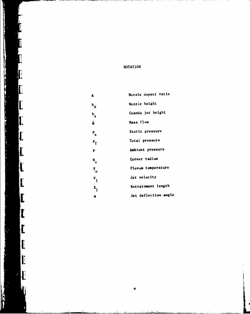
NOTATION
A Nuzzle aspect ratio
hI Nozzle height
h Coanda jet heights
& mass flov
SP Static pressure
SPT Total pressure
P Ambient pressure
Rt Corner radiusC
T Plenum temperature
I VJet velocity
Ent4traftent length
loJet deflection angle
]I'I
Sv
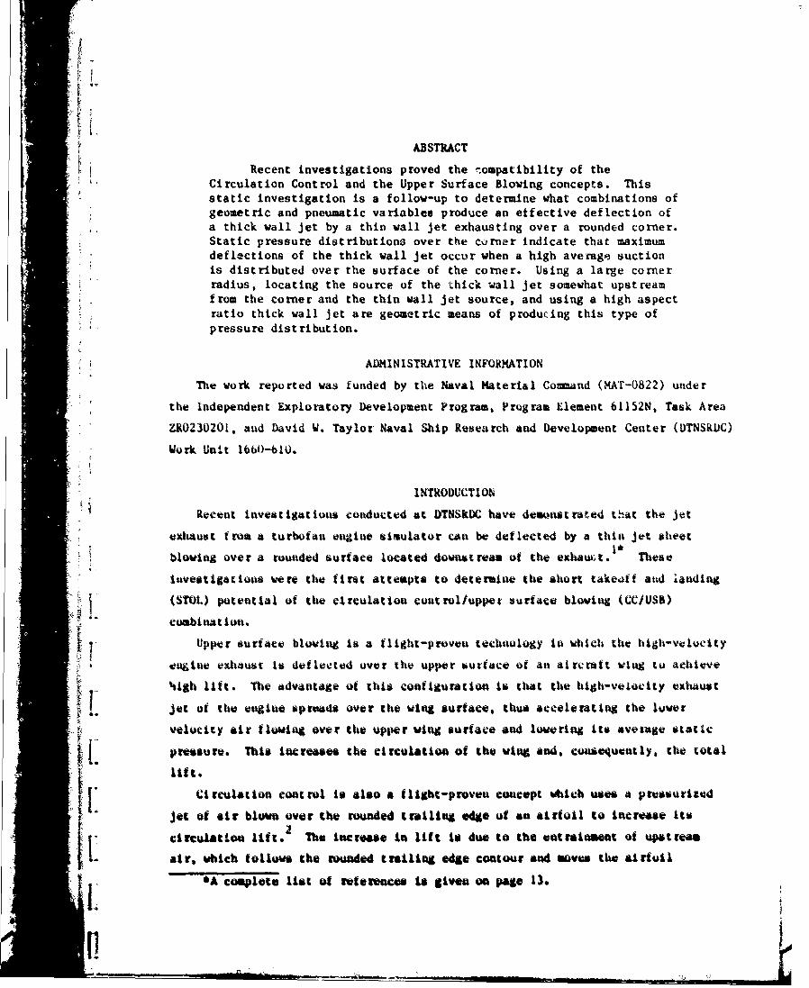
ABSTRACT
Recent investigations proved the rompatibility of theCirculation Control and the Upper Surface Blowing concepts. Thisstatic investigation is a follow-up to determine what combinations ofgeometric and pneumatic variables produce an effective deflection ofa thick wall jet by a thin wall jet exhausting over a rounded corner.Static pressure distributiona over the corner indicate that maximumdeflections of the thick wall jet occur when a high average suctionis distributed over the surface of the corner. Using a large cornerradius, locating the source of the 'thick wall jet somewhat upstreamfrom the corner and the thin wall jet source, and using a high aspectratio thick wall jet are geometric means of producing this type ofpressure distribution.
"ADMINISTRATIVE INFORMATION
The work reported was funded by the Naval Material Command (MA'-0822) under
the Independent Exploratory Development Program, Program Element 61152N, Task Area
ZR023020I, and David W. Taylor Naval Ship Research and Development Center (DTNSRUC)
Work Unit 166b-610.
INTRODUCTION
Recent investigations conducted at DTNSKIX have demwnstrated that the jet
exhaust from a turbofan engine simulator cAn be deflected by a thin jet aheet1'
blowing over a rounded surface located downstream of the exhaw~t. These
investigations were the first attempta to determine the short takeoff and �anding
((STOL) potential of the circulation control/upper surface blowing (CC/US11)
combination.
i v• Upper surface blowing is a flight-proven technology in which the high-velocity
getnie exhaust to deflected over the upper ouriace of an airc-aft wing to aehieve
htigh lift. The advantage of this configuration is that the high-velocity exhaust
t jet oa the engine sprads over the wing surface, thus accelerating the lower
velocity air tlowing over the upper wing surface and lowering Its average static
pressure. Ts increased the circulation of the wing and, Consequently, the total
lift.
U Circulation control ti also a flight-proven concept wtich uses a pressurized
jet of sir blown over the rounded trcaling edge of an airfoil to Increase Its2
circulation lift. The tacrease to lift ti due to the entrainment of upstream
air, which tollow the rounded trailin edge contour and saves the airfoil
*A complete list of references is given on Me 13.
* p'
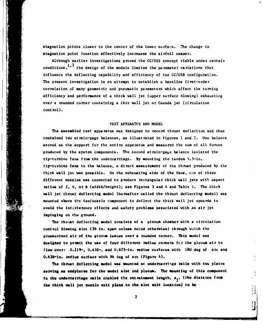
stagnation points closer to the center of the lower surface. The change in
stagnation point location effectively increases the airfoil camber.
Although earlier investigations proved the CC/USB concept viable under certain1,3 dsg
conditions, the design of the models limited the parameter variations that
influence the deflecting capability and efficiency of the CC/USB configuration.
The present investigation is an attempt to establish a baseline first-order
correlation of many geometric and pneumatic parameters which affect the turning
efficiency and performance of a thick wall jet (upper surface blowing) exhausting
over a rounded corner containing a thin wall jet or Coanda jet (circulation
control).
TEST APPARATUS AND MODEL
The assembled test apparatus was designed to record thrust deflection and thus
contained two strain-gage balances, as illustrated in Figures I and 2. One balance
seived as the support for the entire apparatus and measured the sum of all forces
produced by the system components. The second strain-gage balance isolated the
tip-turbine fans from the undercarriage. By mounting the tandem 5.5-in.
tip-turbine fans to the balawict, a direct measurement ef the thrust produced by the
thIck wall jet was possible. On the exhausting side of the fans, one of three
different nozzles ws coanected to produce rectangular thick uall jets with 4spect
ratios of 2, 4. or 6 (width/height); see Figures 3 and 4 and Table 1. The thick
wall Jet thrust deflectlr model (hereafter called the thruit deflecting model) was
unoted %bove tihe fau/nozzle component to deflect the thick wall jet upwards to
avoid the int-rfereace effects. •ad safety problems associated with an air jet
impinging on the grouud.
The th',r4t deflecting model consists of a plenum chamber with a circulation
control blowing slot (36 in. span unless nuoed otherwise) through itaich the
prssurized air of the plennm issues over a vounded corner. This model was
designe to porit the use of four different radius comets fcr the pleaum air to
flow over: 0.219-, 0.438-. and 0.875-in. radius surfaces with 180 deg of arc and
0.438-in. radius surface with 96 deg of art (Figure 4).
The thrust deflecting model wu mounted oa undercarriage rails with two plates
serving as endplates for the model slot and plenum. The mounting of this component
to the undercarriage rails enabled the entraiawnt length, xj, (the distance firo
the thick wall jet nozzle exit plane to the slot exit locatiou) to be
2
varied from 0 to 10.9 in. In addition to the variation of entrainment length and
corner radius, the span of the blowing slot and corner could be changed.
The compressed air to drive the tip-turbine fans ranged to 215 psig, yielding
thick wall jet thrust values up to 90 lb. Table 2 provides the conversions from
thrtist percentage to nominal pounds of thrust. The compressed air supplied to the
plenum could also be varied, which permitted a Coanda jet momentum (&V ) range of
0 to 62 lb.
The rounded corners of the thrust deflecting model were designed with static
pressure taps located at 10 to 30 deg intervals, depending on the radius of the
corner. Pressure taps also were located between the thick wall jet nozzle and the
blowing slot at 1-in. intervals. On the surface downstream frcm the rounded
corners, the pressure taps were located with the same spacing and extepded 6 in.
"forward from the corners.
The investigation was conducted in the breather tank of the transonic wind
tunnel test section. This location provided access to two sources of compressed
air as well as the necessary electronics to record data. In addition to the nozzle
and system force measurements, tempera. ire as well as static and total pressure
measurements were recorded.
All pressure control valves and data recording equipment wert located in the
wind tunnel control room. This location isolated the test personnel from noise
generated by the tip-turbine fans and from potential hazards of the compressed air
ptpe&g and hoses.
Because of the static nature of this investigation and the lack of a chord
dimension for the thrust deflecting model, presentation of the data in the typical
coefficient form was not possible. Therefore, blowing twmentu coefficient vws
replaced with blowing momentum, it, (b); rounded corner radius-to-chord ratio with
corner radius, e (kn.); and static pressure coefficient with pressure ratio,
P /P . The mowmtum of the circulation control blowing jet was computed as the
* product of mass flow per unit span and the blowing jet velocity. Mass flow, A. was
measured with a venturimeter; jet velocity, Vio was calculated using the isentropicjet velocity equation.
I"
IV
A!
* A 3
iib
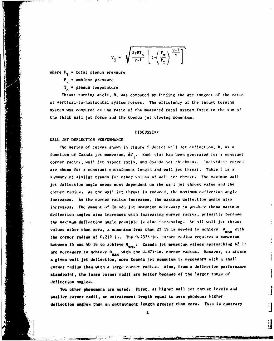
' LR. [ I - ]
where PT - total plenum pressure
PM - ambient pressure
T 0 plenum temperature
Thrust turning anele, 0, was computed by finding the arc tangent of the ratio
of vertical-to-horizontal system forces. The efficiency of the thrust turning
system was computed as -he ratio of the measured total system force to the sum of
the thick wall jet force and the Coanda jet blowing momentum.
DISCUSS ION
WALL JET DEFLECTION PERFORMANCE
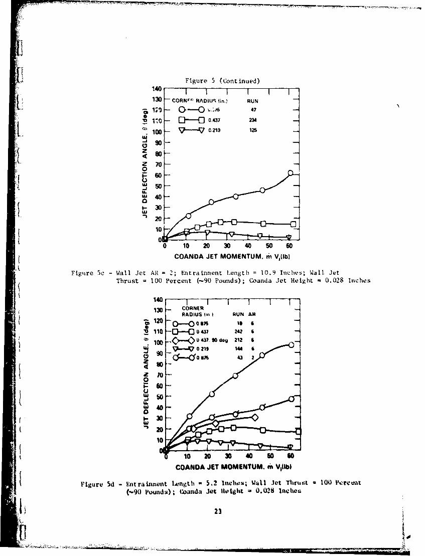
The series of curves shown in Figure 5. depict wall let deflection, 0, as a
function of Coanda let momentum, &V Each plot has been generated for a constantj
corner radius, wall Jet aspect ratio, and Coanda jet thickness. Individual curves
are shown for a constant entrainment length and wall jet thrust. Table 3 is a
sumpary of similar trends for other values of wall jet thrust. The maximum wall
jet deflection angle seems most dependent on the wa)l jet thrust value and the
corner radius. An the wall Jet thrust is reduced, the maximum deflection angle
increases. As the corner radius increases, the maximum deflection angle also
increases. The amount of Coanda Jet momentum necessary to prodijce these maximum
defleetion angles also increases with increasing curner radius, primarily because
"the maximums deflection angle possible is also increasing. At all wall jet thrust
values other than rer-. a amkaentum lese than 25 lb is needed to achieve a withMax
the corner radius of 0.21) in. The 0.4375-in. corner radius requires a momentum
between 25 and 40 lb to 3chieve ea* Coanda jet wamer.tua values approaching 62 lbuax
are necessary to achieve 0 with the 0.87S-in. eorner radius. Houever, to attain
a given wall jet deflection, more Coaeda jet aomentum is necessary with a small
corner radius than with a large cornet radius. Alan, from a deflection performance
standpoint, the large corner radii are better because of the larger range of
deflection angles.
Two other phenomena are noted. First, at higher wall jet thrust levels and
umller corner radii, ae entrainment length equal to zero produces higher
deflection angles than an entrainment length greater than zero. Thie it contrary
4
to other data, which indicates that increasing entrainment length improves wall jet
deflection performance. The probable cause for this phenomenun is the vectoring of
the exhaust jet due to the thick wall jet nozzle design. The wall jet exhaust does
not exit the nozzle parallel to the surface of the thrust turning model. Instead,
the exhaust is vectored at an angle providing some "built-in" deflection when the
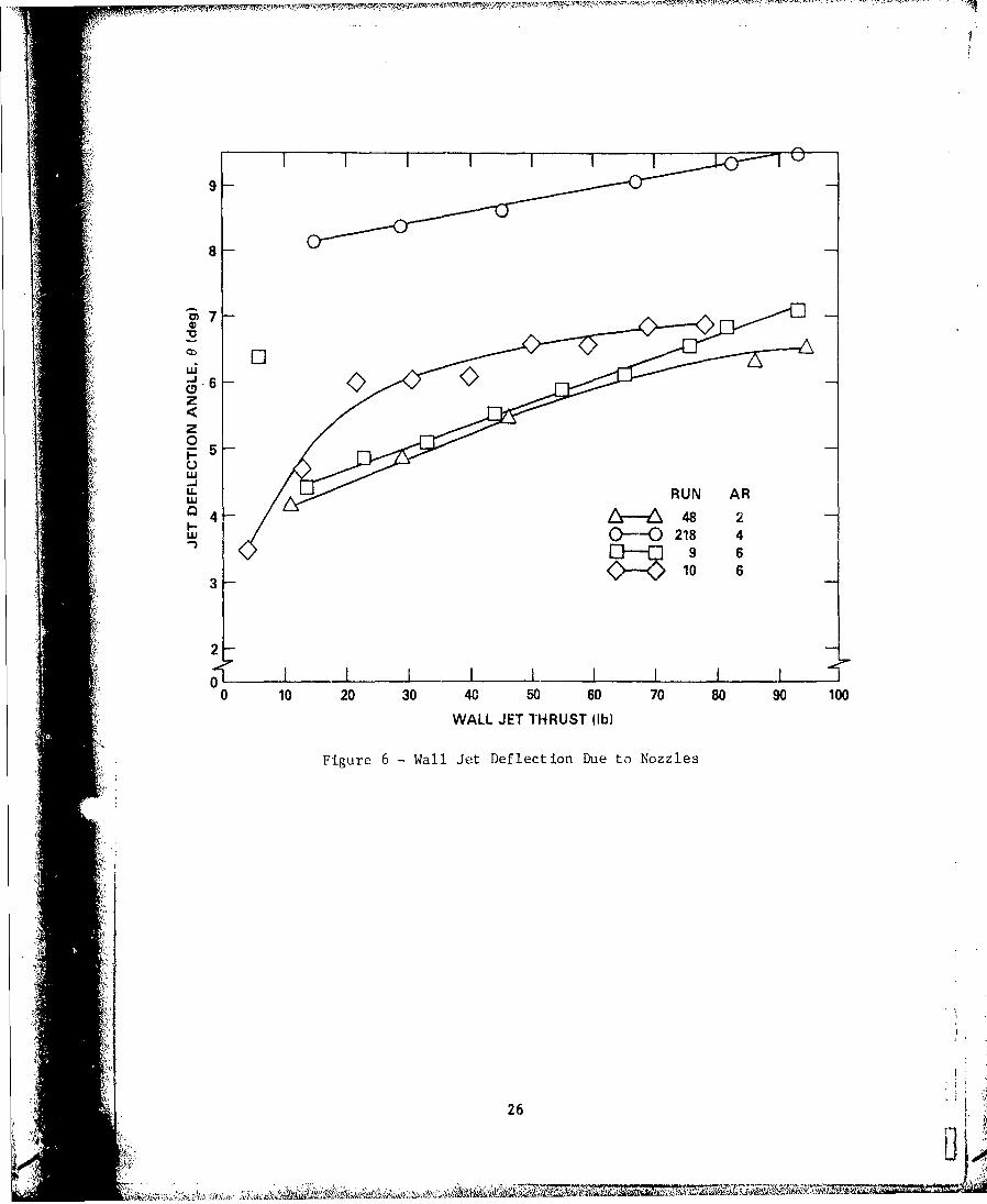
entrainment length is zero. Figure 6 illustrates the vectoring of the vail jet by
the nozzle alone. As the entrainment length is increased, the benefit of the
angled wall jet decreases because the jet is directed into the surface of the
thrust turning model rather than parallel to it.
The second phenomenon is illustrated in Figure 5d by the 0.438-in. radius
corners. When all other conditions are the same, the corner having only 96-deg arc
deflects the thick wall jet more than the corner with the full 180-deg arc. The
sharp trailing edge of the 96-deg corner causes the wall jet to separate at the
sharp edge resulting in wall jet deflections close to 96 deg at nearly all levels
of Coanda Jet momentum. Th" wall jet separation point of the full 180-dog arc
corner moves as well as the vail jet deflection angle depending on the Coanda jet
momentum level and other geometric concz.rions. The full arc corner, however, does
have an advantage over the corner with only 96 deg of are. When coupled with other
more favorable parametric combinations, the full arc corner can produce a range of
deflection angles up to 180 deg. A partial arc is limited to a smaller range of
deflection angleo.
DEFLECT ION EfftC!INCY
The deflectioa efficiency is nfluetnced most by corner radius, wall let aspect
"ratio, and entrainment length. Tth efficiency of the vai• j~t thrust deflection is
Slthe ratio of resultaft thrust to the sum of wall jet thrust and Caanda jet
am entum. For wall jec deflection angles of iess than S dog. the etficietcy is
1.0. This implies that no thrust to lost due to suall wall jot deflection; there
is simply a slight change in thrust direction.
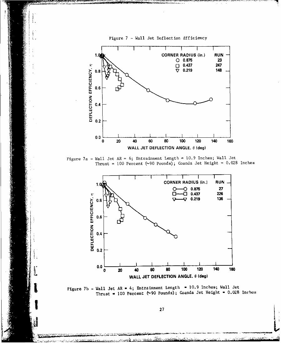
The wall jet deflection effieiency Improves as the corner radtiu increases
(Figure 7). At small deflection angles, the mail jet deflection otfictinewo, are
nearly the vase for all the corner rad.i; however, as the angle of deflection
K : increases, the deflection efficienctes of the smaller corner radii decrease more
rapidly.
"Increasing wall jet aspect ratio tmproves the deflection efficiency. Results
•Lk'• -•7- .- -;•_,. :•_ ... :, . ,=-''--• - -• - : . -- .-- I-- • =..•••-- • 'm -
of the aspect ratios investigated indicate that there is a diminishing incremental
increase in efficiency for increasing aspect ratio. For most conditions, the
difference in efficiency is very small when comparing the aspect ratio 4 and 6 wall
Jets, but not when comparing the aspect ratio 2 wall jet. When the entrainment
length is zero, the aspect ratio 4 wall jet actually is mcre efficient than Ne
aspect ratio 6 vail Jet.
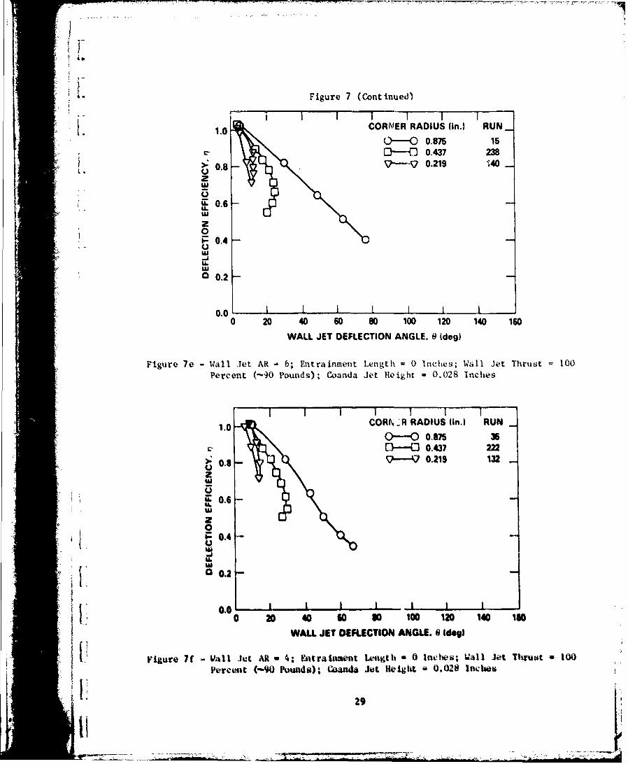
The deflection efficiency seems to improve with decreasing entrainment lngth;
see Figure 7. The curves illustrate that the 0.875-in. corner radius h*.
deflection capability limited only by the amount of Coanda jet momentum available.
When these curves of various entrainment lengths are compared, the uŽ.st efficient
deflections occur when the entrainment length is zero. This behavior is attributed
to the vectoring of the vail jet nozzle, as discussed earlier.
Whnn the curves in Figure 7 are shifted to give the name deflection arngles for
no Coanda jet M.Ioving, deflection efficiency is only slightly improved by
increasing entrainment length. The smaller corner radii follow the s2me Lrends as
thl 0.875-in. radius; however, these radii are limited to the maximum deflection
angle attainable.
STATIC PRUSU" DISTRIAUTION AT C0kNUR
Figurt 8 shows statie pressure at the smallest corfor ra4ius (0.219 it-.). The
flow is mostly separated over the Coand4 surface. The static presutre varies nvar
* the (aiada jet *lot, however, only one tap was elosr enough to the olot to piek op
the pressure variations. The preosuse variations are limited to a very "mall area,
whiet means that there is no attached flow over *aat of the thrtist tutning coreor.
These conditions indicate tht a presstue cha€ e over a very sLall area can
signifieantly change the wall jet defleoeion angle.
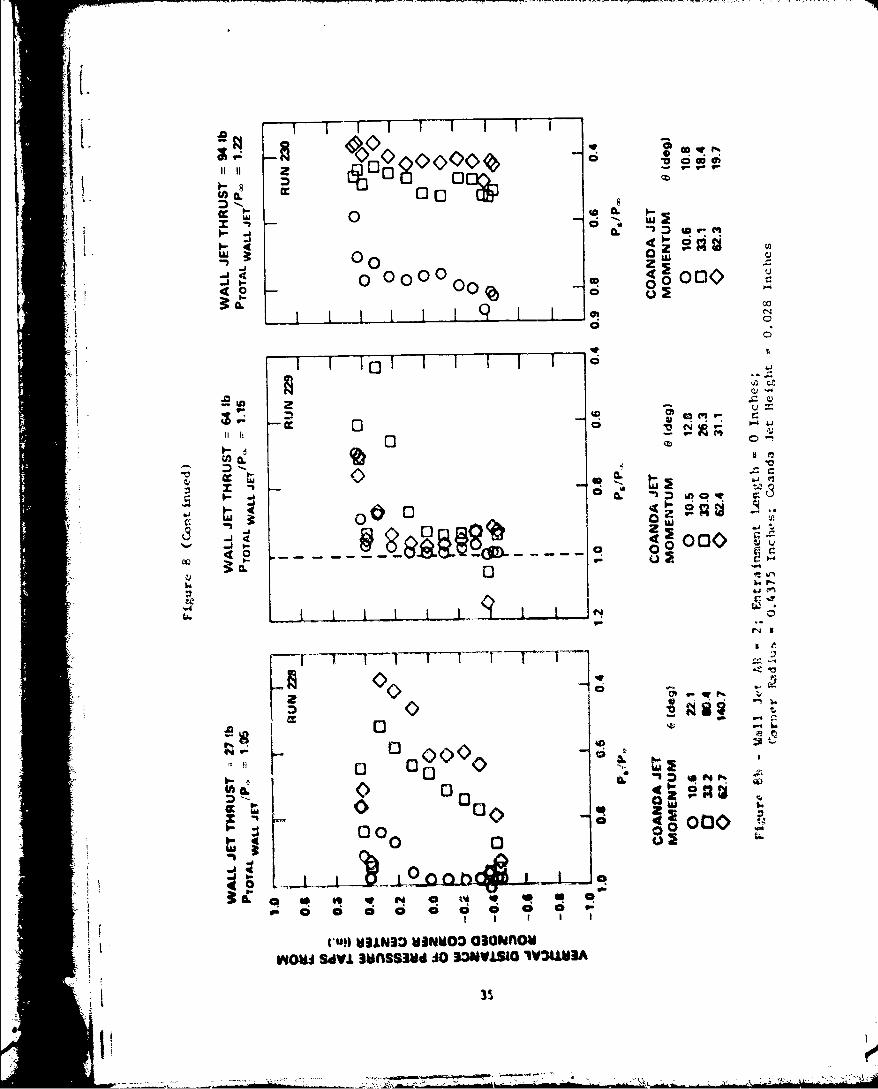
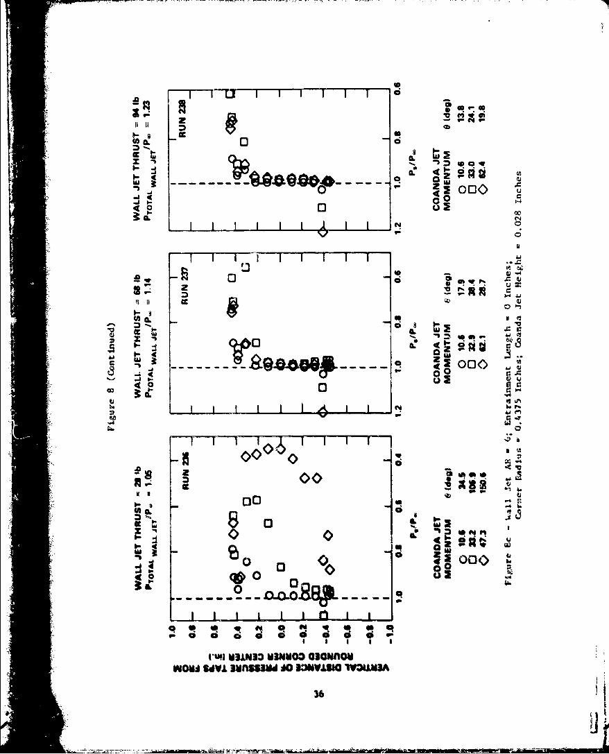
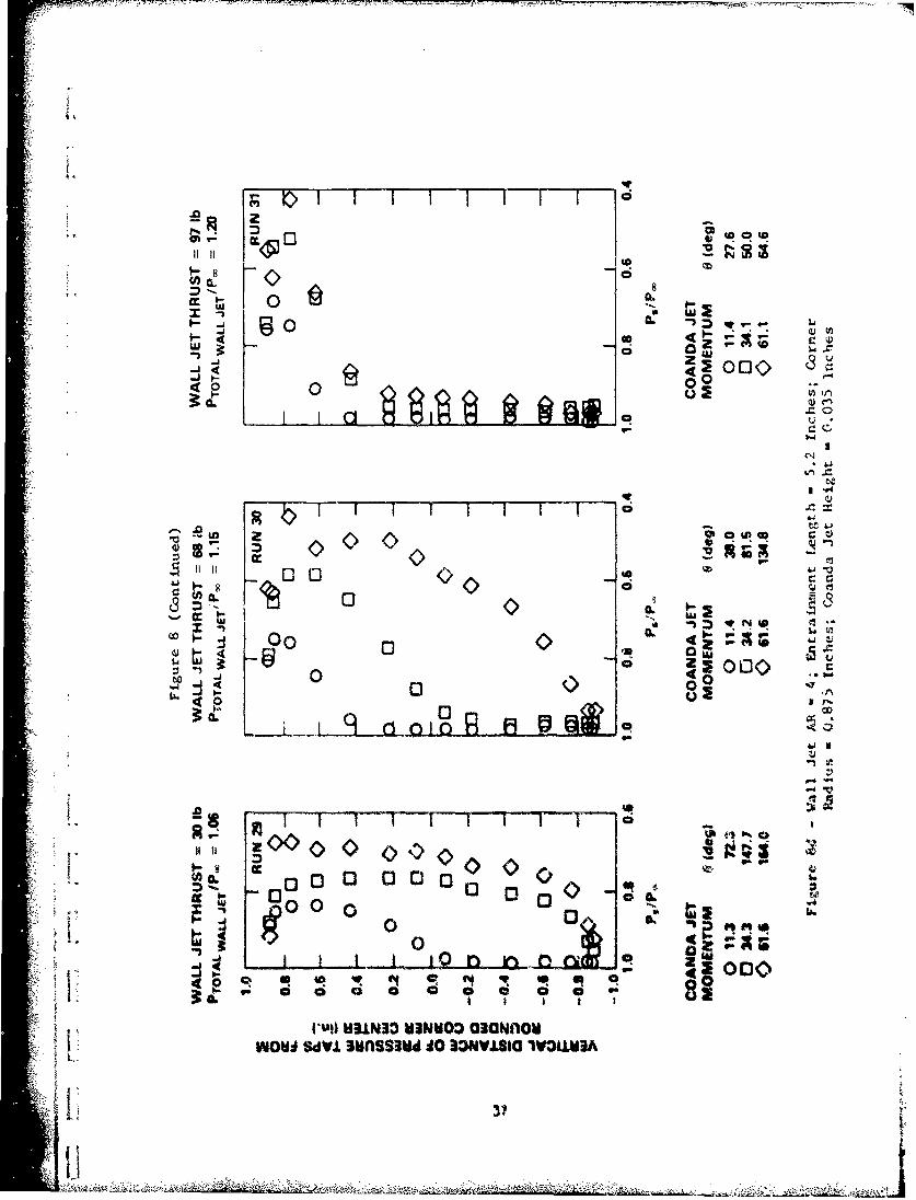
The largor vorner radii (0.4U and 0Si.S in.) at low wall jet thrust :eveol
(•gures 8b through 8) show that a high suctitoo average over the entire surface
results in high vall jet thrust dvflecttoa saols. Lees than optimum conditions
can still produce -trae deflection* of the wall jet. Vith an incre•asd wolt l•t
thrust, the amount of suction necessary to deflect the wall jet thrust ts
increased. Alsn, t0 suction near the Coanda Jet slot ts irtereade, and the
suction on the rest of th, thrust turning career to decreased. lnsuff4cient COafa
jet blowing or exceestvw bloutni produces the Oaum type of pressure distribution on
6 :
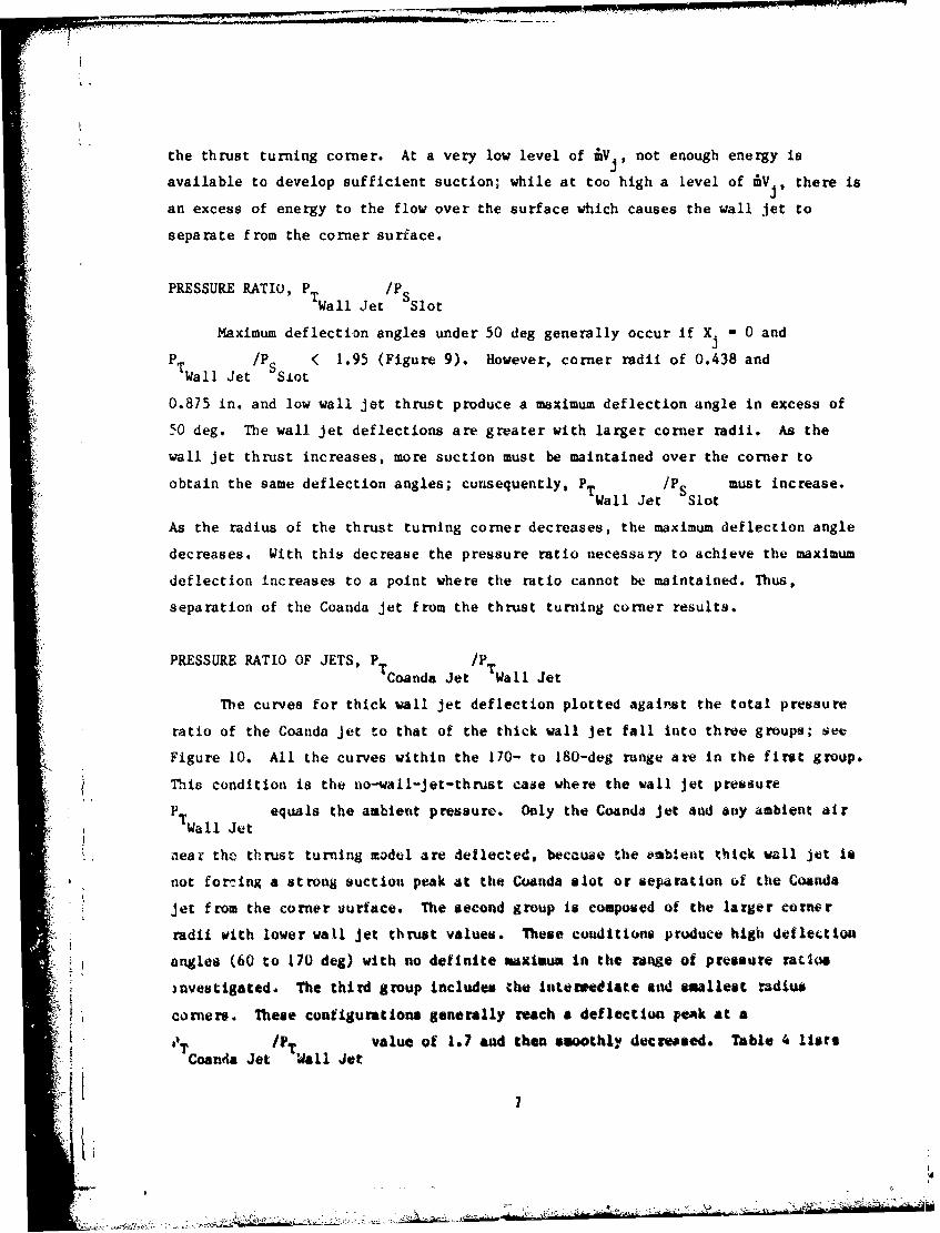
the thrust turning corner. At a very low level of i~.not enough energy is
available to develop sufficient suction; while at too high a level of 11V, there is
an excess of energy to the flow over the surface vhich causes the wall jet to
separate from the corner surface.
PRESSURE RATIO, P T /Wall Jet slot
Maximum deflection angles under 50 deg generally occur if X j.0 and
STWal J' P S Slt( 1.95 (Figure 9). However, corner radii of 0.438 and
0.875 in. and low wall jet thrust produce a maximum deflection angle in excess of
50 deg. The wall jet deflections are greater with larger corner radii. As the
wall jet thrust increases, more suction must be maintained over the corner to
obtain the same deflection angles; consequently, PT /P must increase.Wall Jet Slot
As the radius of the thrust turning corner decreases, the maximum deflection angle
decreases. With this decrease the pressure ratio necessary to achieve the maximum
deflection increases to a point where the ratio cannot be maintained. Thus,
separation of the Coanda jet from the thrust turning corner results.
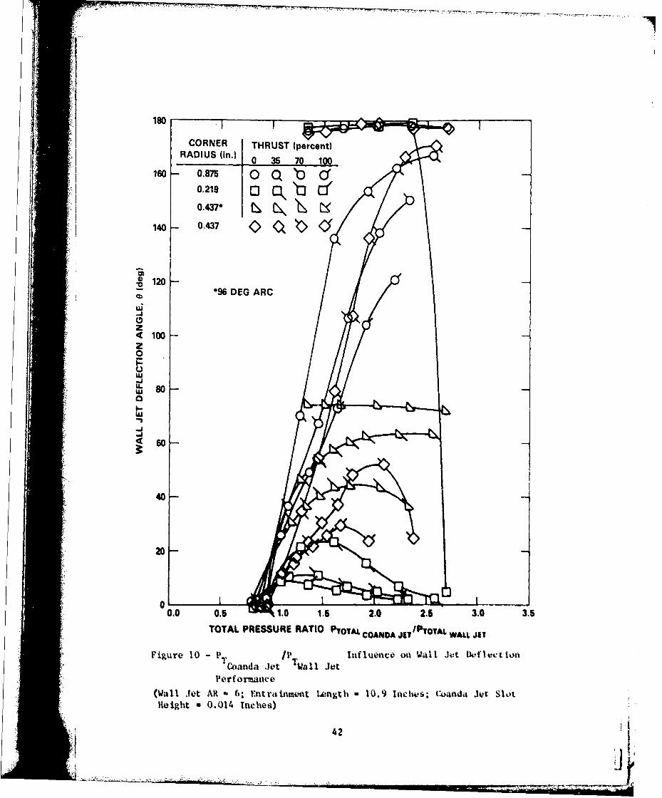
PRESSURE RATIO OF JETS, PT/Coanda Jet Wall Jet
Thle curves for thick wall jet deflection plotted against the total pressure
ratio of the Coanda jet to that of the thick wall jet fall into three groups; see
Figure 10. All the curves within the 110- to 180-deg range arm in the first group.
This condition is the no-wall-j et-th rust case where. the wall jet pressure
P Twal etequals the ambient pressure. Only the Coands jet awd any ambient air
niear thc thrust turning model are 4eflecled, becauae 'he rambent thick wall jet is
not forming a strong suction peak at the Cuanda slot or separation of the Coanda
jet from the corner uurface. The second group Is composed of the larger corner
radii with lower wall jet thrust values. These conditions produce high deflection
angles (60 to 170 deg) with no definite maximum In the range of pressure ratios
investigated. The third group Includes the interu'ediate and smallest radius
corers. These configurationa generally reach & deflection Ve~k at a
OT oada et/P Wal etvalue of 1.7 and then smoothly decreased. Table 4 lists
Coanta Je i~al Je
~i tA6
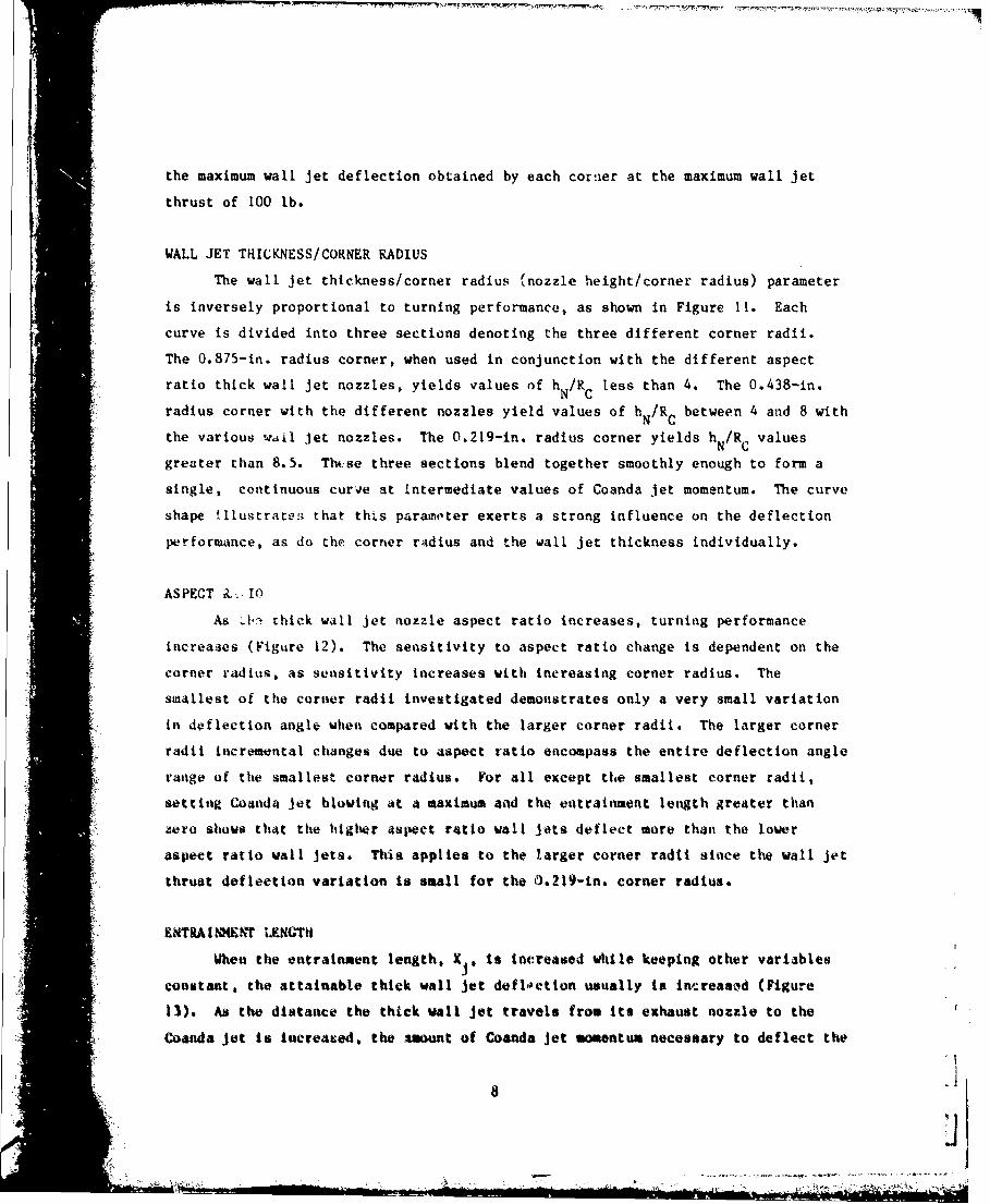
the maximum wall Jet deflection obtained by each cornier at the maximum wall jet
thrust of 100 lb.
WALL JET THICKNESS/CORNER RADIUS
The wall jet thickness/corner radius (nozzle height/corner radius) parameter
is inversely proportional to turning performance, as shown in Figure 11. Each
curve is divided into three sections denoting the three different corner radii.
The 0.875-in. radius corner, when used in conjunction with the different aspect
ratio thick wall jet nozzles, yields values of h N/RC less than 4. The 0.438-in.
radius corner with the different nozzles yield values of h /R between 4 and 8 withN C
the various wail jet nozzles. The 0.219-in. radius corner yields h /R valuesN C
greater than 8.5. Thcse three sections blend together smoothly enough to form a
single, continuous curve at intermediate values of Coanda jet momentum. The curve
shape illustrates that thts parameter exerts a strong influence on the deflection
performance, as do the corner radius and the wall jet thickness individually.
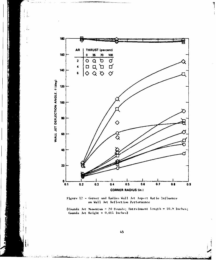
ASPECT it. 1O
As J1-ý thick wall jet nozzle aspect ratio increases, turning performance
increases (Figure 12). The sensitivity to aspect ratio change is dependent on the
corner radius, as sensitivity increases with increasing corner radius. The
smallest of the corner radii investigated demonstrates only a very small variation
in deflection angle when compared with the larger corner radii. The larger corner
radii incremental changes due to aspect ratio encompass the entire deflection angle
range of the smallest corner radius. For all except the smallest corner radii,
setting Coanda jet blowing at a maximum aad the entrainment length greater than
zero shows that the higher aspect ratio wall Jets deflect more than the lower
aspect ratio wall Jets. This applies to the larger corner radii since the wall jet
thrust deflection variation is small for the 0.219-in. corner radius.
ENTRA1NES1 LENGTH
When the entrainment length. XJ, is increased while keeping other variables
constant, the attainable thick wall Jet deflctton usually is IncreasMd (Figure
13). As the distance the thtck wall jet travels from its exhaust nozzle to the
Coanda jet is Increased, the amount of Coanda jet momentum necessary to deflect the
l o
"• ' "• - -N i &- • " • • •, -l • • i• • ' ' •" :••" .. :' "i•'•:"|'-
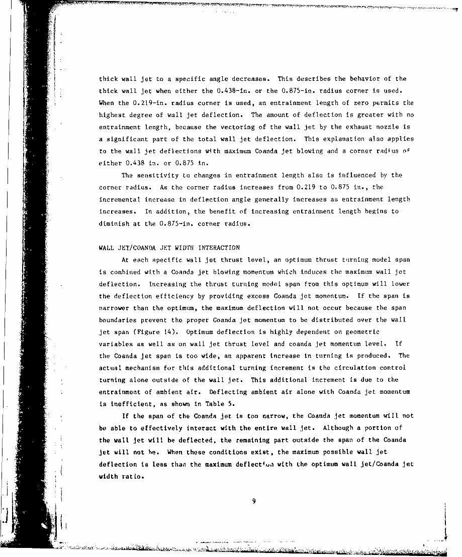
thick wall jet to a specific angle decreases. This describes the behavior of the
thick wall jet when either the 0.438-in. or the 0.875-in. radius corner is used.
When the 0.219-in. radius corner is used, an entrainment length of zero permits the
highest degree of wall jet deflection. The amount of deflection is greater with no
entrainment length, because the vectoring of the wall jet by the exhaust nozzle is
a significant part of the total wall jet deflection. This explanation also applies
to the wall jet deflections with maximum Coanda jet blowing and a corner radius oF
either 0.438 in. or 0.875 in.
The sensitivity to changes in entrainment length also is influenced by the
corner radius. As the corner radius increases from 0.219 to 0.875 in., the
incremental increase in deflection angle generally increases as entrainment length
increases. In addition, the benefit of increasing entrainment length begins to
diminish at the 0.875-in. corner radius.
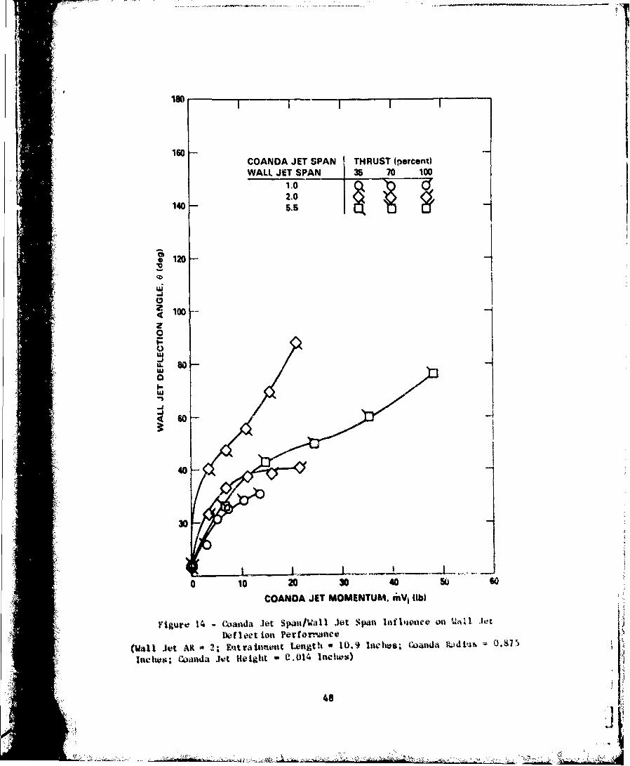
WALL JET/COANDA JET WIDTH INTERACTION
At each specific wall jet thrust level, an optimum thrust turning model span
is combined with a Coanda jet blowing momentum which induces the maximum wall jet
deflection. Increasing the thrust turning model span from this optimum will lower
the deflection efficiency by providing excess Coanda jet momentum. If the span is
narrower than the optimum, the maximum deflection will not occur because the span
boundaries prevent the proper Coanda jet momentum to be distributed over the wall
jet span (Figure 14). Optimum deflection is highly dependent on geometric
variables as well as on wall jet thrust level and coanda jet momentum level. If
the Coanda jet span is too wide, an apparent increase in turning is produced. The
actual mechanism for this additional turning increment is the circulation control
turning alone outside of the wall jet. This additional increment is due to the
entrainment of ambient air. Deflecting ambient air alone with Coanda jet momentum
is inefficient, as shown in Table 5.
If the span of the Coanda jet is too narrow, the Coanda jet momentum will not
be able to effectively interact with the entire wall jet. Although a portion of
the wall jet will be deflected, the remaining part outside the span of the Coanda
* jet will not he. When these conditions exist, the maximum possible wall jet
deflection is less than the maximum deflect'.u, with the optimum wall jet/Coanda jet
width ratio.
9
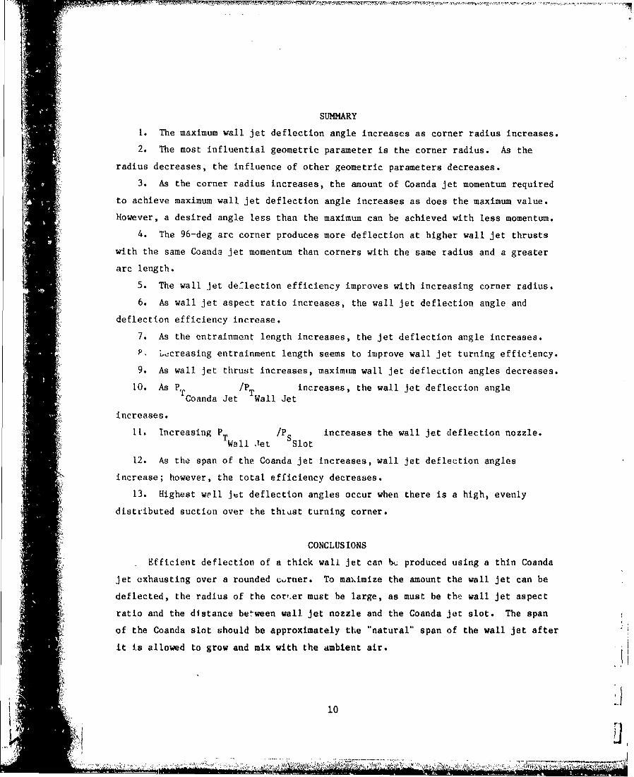
SUMMARY
1. The maximum wall jet deflection angle increases as corner radius increases.
2. The most influential geometric parameter is the corner radius. As the
radius decreases, the influence of other geometric parameters decreases.
3. As the corner radius increases, the amount of Coanda jet momentum required
to achieve maximum wall jet deflection angle increases as does the maximum value.
However, a desired angle less than the maximum can be achieved with less momentum.I 4. The 96-deg arc corner produces more deflection at higher wall jet thrusts
with the same Coanda jet momentum than corners with the same radius and a greater
arc length.
5. The wall jet de'lection efficiency improves with increasing corner radius.
6. As wall jet aspect ratio increases, the wall jet deflection angle and
deflection efficiency increase.
7. As the entrainment length increases, the jet deflection angle increases.
P. L-creasing entrainment length seems to improve wall jet turning efficiency.
9. As wall jet thrust increases, maximum wall jet deflection angles decreases.
10. As P /Pw ncreases, the wall jet deflection angleTCoanda Jet TWall Jet
increases.
I1. Increasing PTI /P increases the wall jet deflection nozzle.Wall Jet Slot
12. As the span of the Coanda jet increases, wall jet deflection angles
increase; however, the total efficiency decreases.
13. Highest well jet deflection angles occur when there is a high, evenly
distributed suction over the thiast turning corner.
CONCLUSIONS
Efficient deflection of a thick wall jet car bL; produced using a thin Coanda
jet exhausting over a rounded curner. To ma).imize the amount the wall jet can be
deflected, the radius of the corr.er must be large, as must be the! wall jet aspect
ratio and the distance between wall jet nozzle and the Coanda jet slot. The span
of the Coanda slot should be approximately the "natural" span of the wall jet after
it is allowed to grow and mix with the ambient air.
10
"5;, ,& • • ~ ••h•:x :,'•. -•'"•• ... , -... • ••'•?. °'. •. .:" • .. ."o " • " ,• ••:i" ,•• ",• '•'••••• •": :' • ' :, , '•' '• .• .'"..

Static pressure ratio distributions over the surface of the corner indicate
that for high deflection angles an even suction distribution over the surface is
required. Given a particular design point, it should be possible to tailor the
shape of the corner to provide the prescribed deflection at a minimum energy cost.
The span of the Coanda jet relative to the wall jet, or the
two-dimensionality, determines the efficiency and effectiveness of the system. The
optimum span ratio is one which limits the span of the Coanda jet to that of the
wall jet after it travels the entrainment length mixing with ambient air. This
condition ensures that the maximum amount of Coanda jet blowing will be used to
deflect the wall jet without permitting excess Coanda blowing to entrain static
ambient air.
ACKNOWLEDGMENTS
The author especially thanks Michael Harris for developing the data reduction
program and assisting in the data collection. Acknowledgment is extended to Ronald
Adams, Louis Cregger, Robert Englar, James Nichols, Jr., and Ossie Steffanelli for
their assistance and interest throughout this investigation.
I.O
! 1
¶1
REFERENCES
1. Harris, M.J., "Investigation of the Circulation Control Wing/Upper
Surface Blowing High-Lift System on a Low Aspect Ratio Semispan Model,"
DTNSRDC/ASED-81/10 (May 1981).
2. Englar, R.J. et al., "Design of the Circulation Control Wing STOL
Demonstrator Aircraft," AIAA Paper No. 79-1842 presented at the AIAA Aircraft
Systems and Technology Meeting, New York (20-22 Aug 1979).
3. Harris, M.J. et al., "Development of the Circulation Control Wing/Upper
Surface Blowing Powered-Lift System for STOL Aircraft," ICAS Paper No. 82-6.5.1
presented at the 13th Congress of the International Council of the Aeronautical
Sciences Meeting, Seattle (22-27 Aug 1982).
13
Jr7 .. --•. ' .. ! •,. . ". . .• < " • • "- : " '•-• - . .... "- ' °: • "
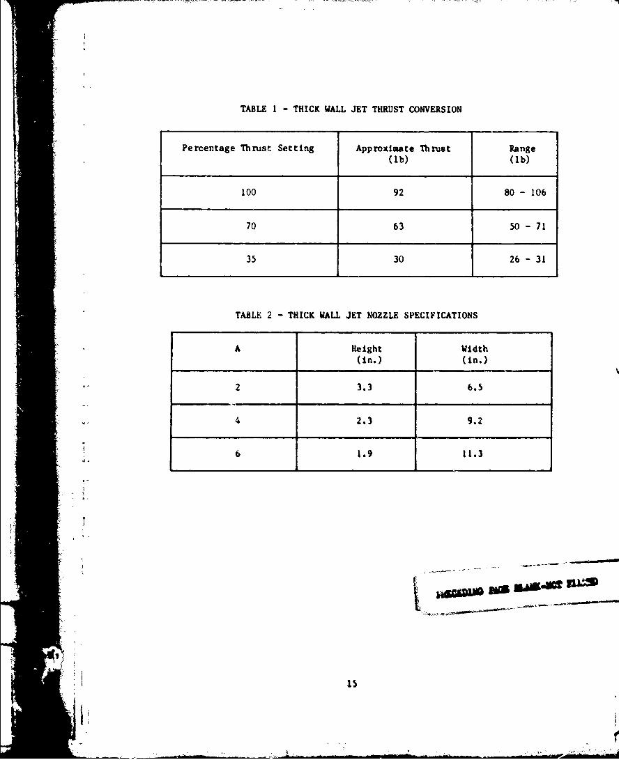
TABLE 1 - THICK WALL JET THRUST CONVERSION
Percentage Thrust Setting Approximate Thrust Range(ib) (Ib)
100 92 80- 106
70 63 50 - 71
35 30 26 -31
TABLE 2 - THICK WALL JET NOZZLE SPECIFICATIONS
A Height Width(in.) (in.)
2 3.3 6.5
4 2.3 9.2
"6 1.9 11.3
~SAO.= IW
Ow
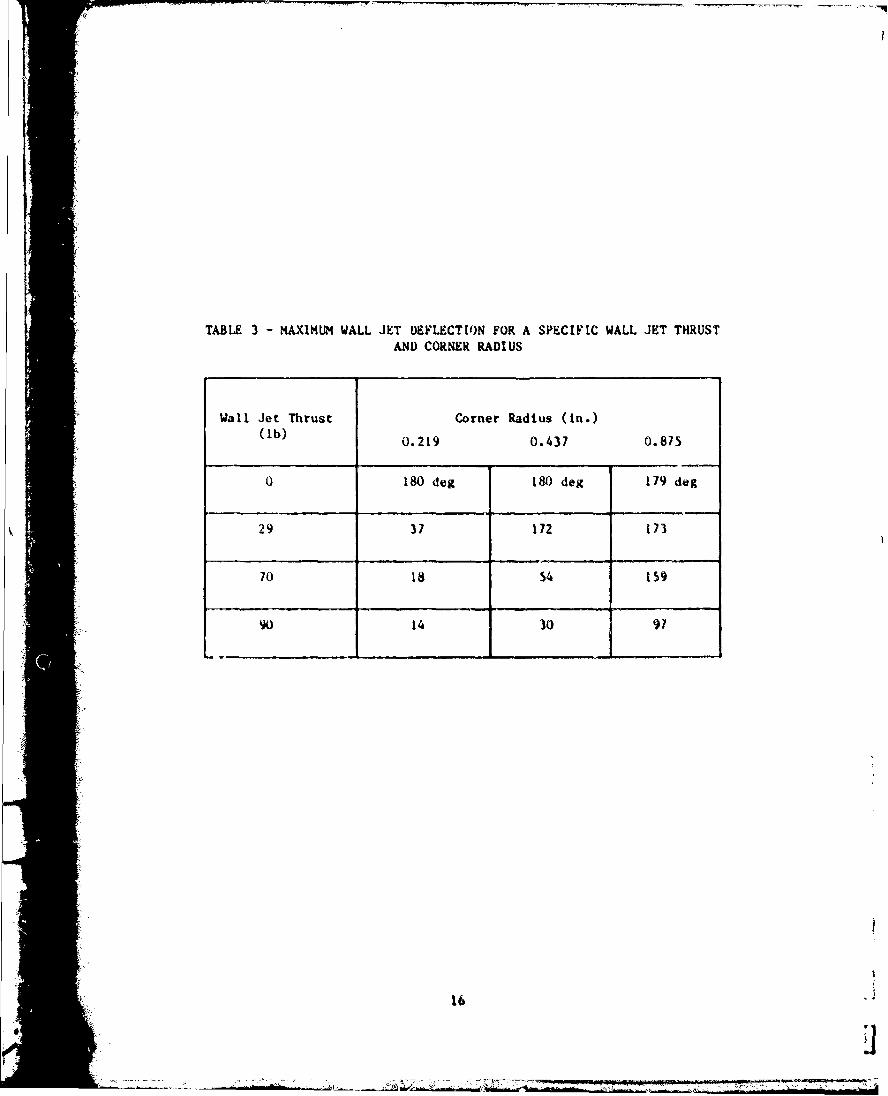
TABLE 3 - MAXIMUM WALL JET DEFLECTION FOR A SPECIFIC WALL JET THRUSTAND CORNER RADIUS
Wall Jet Thrust Corner Radius (in.)(lb) 0.219 0.437 0.875
0 180 deg 180 deg 179 deg
29 37 172 173
70 18 54 159
90 14 30 97
16
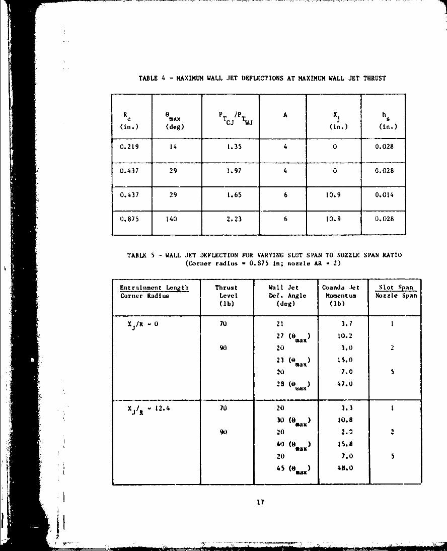
TABLE 4 - MAXIMUM WALL JET DEFLECTIONS AT MAXIMUM WALL JET THRUST
R e P j/P A X hc mxTc T s(in.) (deg) (in.) (in.)
0.219 14 1.35 4 0 0.028
0.437 29 1.97 4 0 0.028
0.437 29 1.65 6 10.9 0.014
0.875 140 2.23 6 10.9 0.028
TABLE 5 - WALL JET DEFLECTION FOR VARYING SLOT SPAN TO NOZZLE SPAN RATIO(Corner radius 0.875 in; nozzle AR - 2)
Kntrtinment Length Thrust Wall Jet Coanda Jet Slot SpanCorner Radius Level Def. Angle Momentum Nozzle Span
(0b) (deg) (Ib)
X/RK 0 70 21 3.7 1
27 ( max) 10.2
90 20 3.0 2
23 (0 m) 15.0
20 7.0
28 (k ) 47.0
X /it 12.4 70 20 3.3 1
0 (a ) 10.890 20 2.3 2
40 (0e) 15.8
20 7.0 5
45 (8 ) 48.0
17
I,. ....: ". . , -. .. .-.. .._ . . .,. ,• -: -- .,
zz
ZZw Lw
0 0A
z D
002w0 0 - _5
zz
Ub2
2dam

4',g
Yigrt±2 -Test 4.pparaLAb
19
I;I:
1K
I;
Elgurt' I - 'Vip-turbine Ltn-, \K 4 Thick W4 11 Irt Xutlr,
4UU Induct �.t LI *ihv
7- -/
� - -- -r-�' ----- ,.---'� -
1' r
1' .1 1i '
figure 4 Comer Wradt of 0.219. 0.4t8, and- 0.875 Inches and Thick Vall Jet Koaaaeo
21
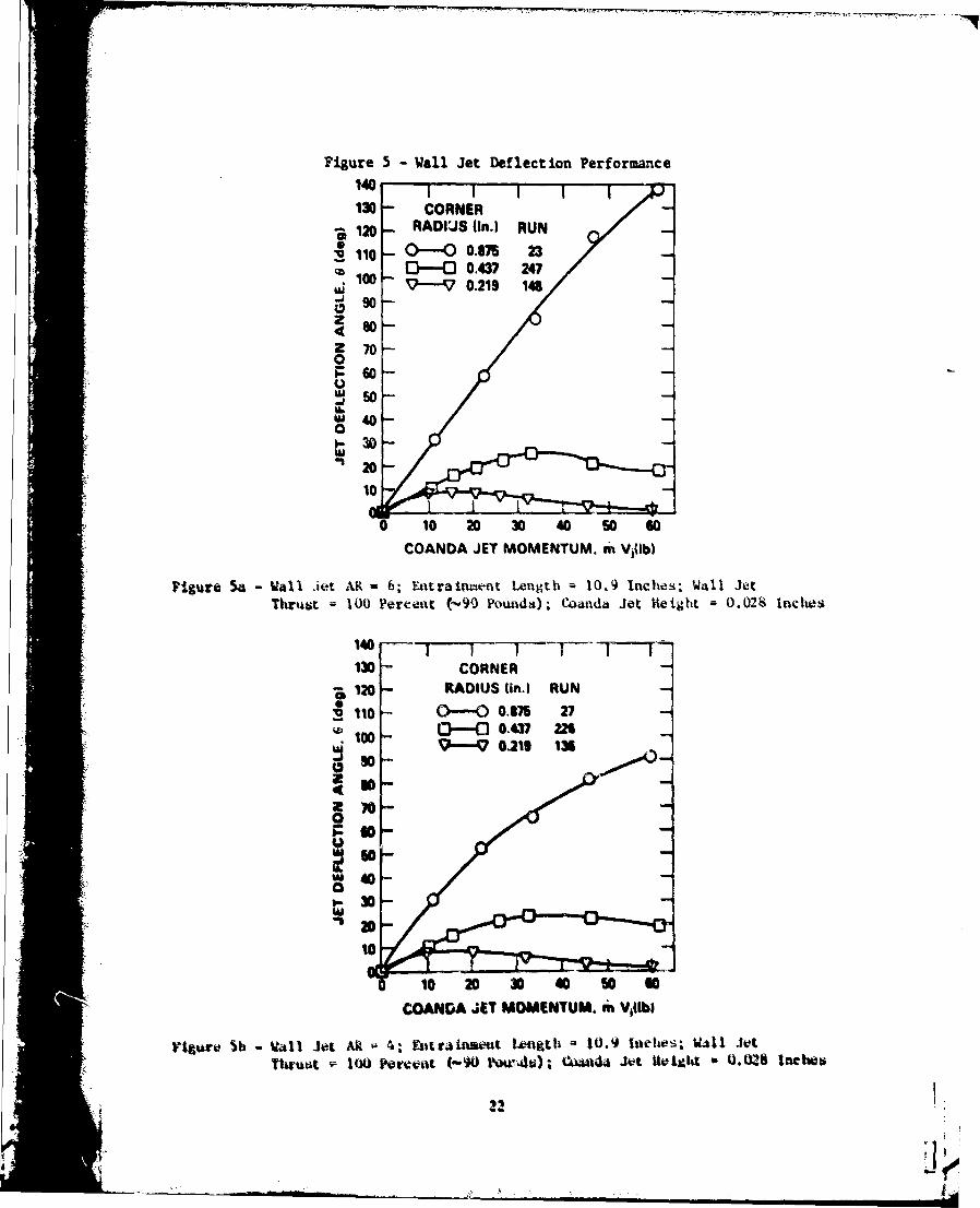
Figure 5 -Wall Jet Deflection Performance
140 1130 - CORNER120 RADIUS tin.) RUN
v110 O---Oo.0,75 2230 - a G--- 0.437 247
10- e A-V 0.219 148
4 so -Z 700U~50
30
201- •lsi. U
-10 1-- 0 Ow8 0 -G
COANDA JET MOMENTUM. m Vilbl
Figure Sa - Wall Jet AR - 6; Entrainment Length 10.9 Inches; wall JetThrust 100 P(rcent (-')0 Pounds); Coanda Jet Hetght 0.028 Inches
130 CORNERS120 RADIUS (in.) RUN110 0--0 0.875 27
..... .. 100 L- - 0.437 M2so %--V 0219 136
40070
COANDA %PIT MOMENTUM. c6Vlb
Figuri 5b - W11 Jo A ; Entraitwe~tf I-0001i -10.9 Inlehe'; VILI J"t(~ui to IOU Ireifl (-w) POQs-4s); CWida Jot HigttbtZ 0.W.8 Inche
17 Figure 5 (Continued)
.401! 130 CORNrr- HAADfIU, (jn) RUN
•- V;O- O---0.3 2i3•47
447. ~ ~100- 0---m., . 12s
Z 70-0~60
U
-- 30--U. 24010
0 10 20 30 40 W 60
COANDA JET MOMENTUM. m VIlb)
Figure Sc - Wall Jet AR - 2; Entrainment Length = 10.9 Inches; Wal1 Jet
( Thrust 100 Percent (-90 Founds); Coanda Jet Height - 0.028 Inches
140 - -- -i I I I - T -1230 - CORNERS1 - RADIUS (in I RUN AR
120 - oov• -
, 110 0---431 24 i-
S -'o 437, s 0 212 6l i "• 380
1.0
90
Pigre d -1~trai~mntCOANDA JET MOMENTUM. m V1Ilb)
I Fgur •) - ntai~aen L~gt ,,•, Itiehes; aill Jet Th~~t - tOO rt~en
(--90 Pounds); • oanda Jet tteight O .O2S ltche•
s'pi
4 so
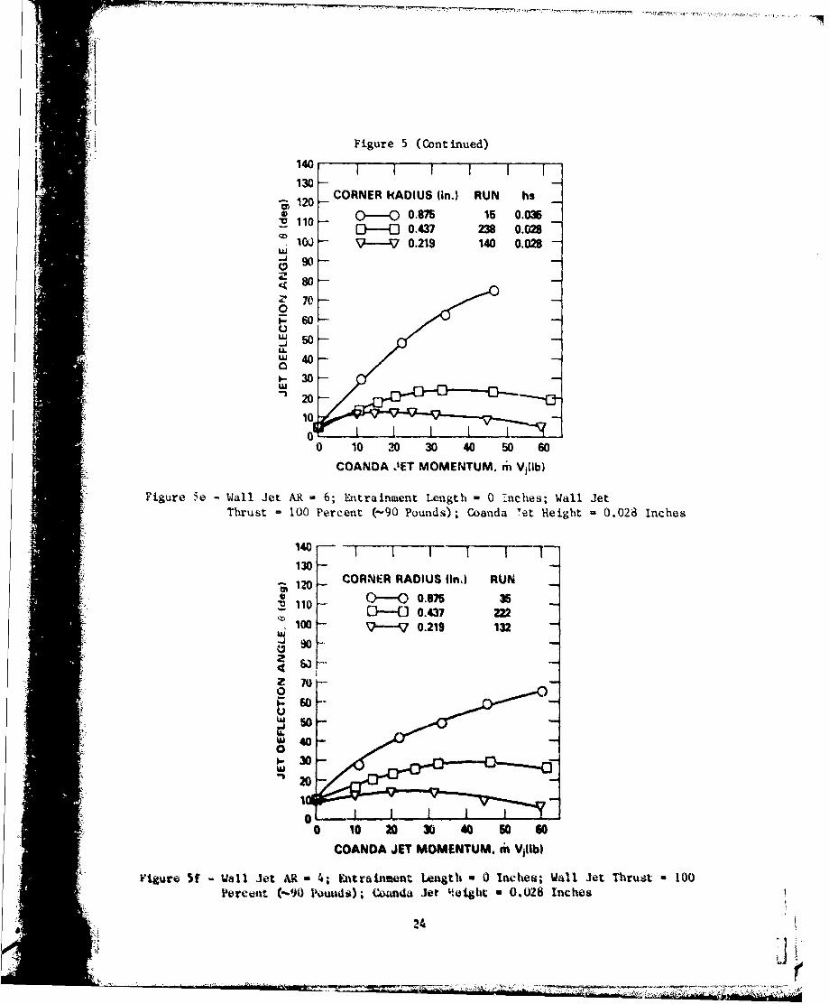
Figure 5 (Continued)
140
S130 -CORNER kADIUS (in.) RUN hs
- 0.875 15 0.03110- [ 0.437 238 0.028iC.- 9 . 0.219 140 0.028
.,(i so --J 0
50
480-
[2 ° 10
5000
• ~COANDA.IET MOMENTUM. 61 Villb)
SFigure 5e- Wall Jet AR -6;, Entrainment Legh-0 -,ceWall JetSThrust= 100 Percent (-.90 Pounds); Coanda Yet Hteight =0.028 Inches
140
10
10 CORNER RADIUS fin.) RUN
1'20
•.". "( ----o 0.875 322i •100 -- • 0.219 132 -
1060
0 10 20 30 40 50 60COANDA JET MOMENTUM. mi Vi1 b)
Figure• f - Wall Jet AR - 6; •ntrainmenat Length w 0 Inches; Wall Jet Thrust -00hrut 10Percent (-90 Pounds); CCdndad jet eihtht 0h028 Inches
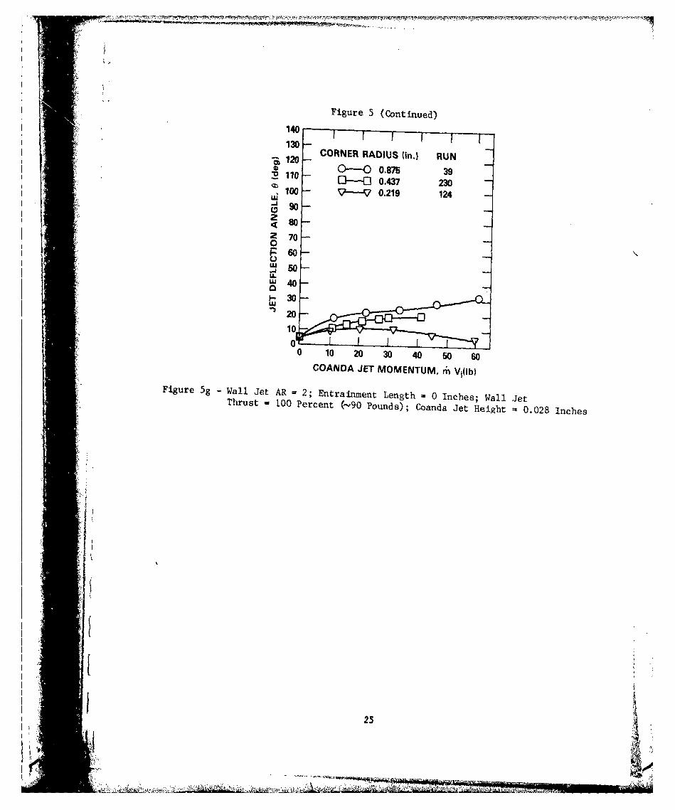
Figure 5(Continued)
140
13010-CORNER RADIUS (in.) RUN
O) -O 0.875 39:R 110 o- .100 - ?j 0.219 124
Z7 0
0
COND JET MOETM mV(Figure 5g - W a ~ll e ) R = 2 n r i m n e g h 0 I c e ; W l eTh us so 10 e c n -Q P u d ) oa d e e g t 0 0 8 I c e
iU
~ -'~ "~30-
9
8
0
C-)U-
214
3
2-
0 1 20 30 40 50 60 70 80 90 100
WALL JET THRUST (Ib)
Figure 6 -Wall Jet Deflection Due to Nozzles
26
M, WIt', n
Figure 7 -Wall Jet Deflection Efficiency
1.0 CORNER RADIUS (in.) RUN0 0.875 230 0.437 247
>:0.8 17 0.219 148z
UL 0.6U.
z0
I-0.4
O0.2
0.010 20 40 60 80 100 120 140 160
WALL JET DEFLECTION ANGLE, 0 (deg)
Figure 7a -Wall Jet AR =6; Entrainment Length = 10.9 Inches; Wall JetThrust =100 Percent (-90 Pounds); Coanda Jet Height =0. 028 Inches
1.CORNER RADIUS (in.) RUN
0--O- 0.875 270-0 0.437 226
>: )0.8 V ---- 0.219 136z
U-0.6wz
C)0.4
IL
00.2
0.0 I
0 20 40 60 90 100 120 140 160
WALL JET DEFLECTION ANGLE, 6 (deg)
Figure 7b -Wall Jet AR -4; Entrainment Length -10.9 Inches; Wall Jet
Thrust 100 Percent (-90 Pounds); Coanda Jet Height *0.028 Inches
27
-1A
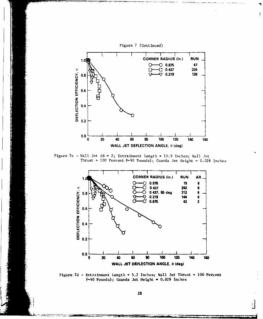
Figure 7 (Continued)
I II I I I
1.0 CORNER RADIUS (in.) RUN _
0----0 0.875 47[){ 0.437 234
> 0.8 • 0.219 128 -zC.)2IL)
L" 0.6LL
z
0N- 0.4
U.IL
0.2
0.0 0 I I I ] I0 20 40 60 80 100 120 140 160
WALL JET DEFLECTION ANGLE. @ (deg)
Figure 7c -Wall Jet AR 2; Entrainment Length = 10.9 Inches; Wall JetThrust 100 Percent (-90 Pounds); Coanda Jet Height = 0.028 Incites
1. CORNER RADIUS (in.) RUN AR
0-0 0.875 19 60-CD 0.437 242 6
>: 0.8 0-0 0.437. 90 deg 212 6z v ,1 144 6_U 0.875 43 2
U.
z0
P0.4-J
00.2
0.0 - I I I I0 20 40 60 80 100 120 140 160
WALL JET DEFLECTION ANGLE. 6 (deg)
Figure 7d - Entrainment Length - 5.2 Inches; Wall Jet Thrust - 0 Percent(-90 Pounds); Coanda Jet Height 0.028 Inches
28
'I.
Figure 7 (Continued)
- II I
S1 .0 CORNER RADIUS fin.) RUN
Q) ---- 0 0.875 15-. ;] 0.437 238
>: 0.8 -'-- .- 0.219 `40
2
E0.6'L,.
0-0.4
LU-JU..'LI
0.2
0.0 1 1 I0 20 40 60 80 100 120 140 160
WALL JET DEFLECTION ANGLE. 9 (deg)
Figure 7e - Wall Jet AR 6; Entrainment Length = 0 Inches; Wall Jet Thrust = 100Percent (-90 Pounds); Coanda Jet Height u 0.028 Inches
1.0 CORN "R RADIUS (in.) RUN
o 0.87 35S• 0.4,37 222
>: 0-8 V6--V 0.219 132 _
UIL
0
r,. 0.4-
U--
V w00.2
I0.SI I I I ,
0.00 20 40 o0 so 100 120 140 160
WALL JET DEFLECTION ANGLE. 6 ide•)
I Figure 7f - all Jet AR - 4; Entr4a1ment Lngtlh a 0 Intelb; Ma1 Je1t Tiruit 1 100
Perceat (-W90 Pounds); Coaft" Jet Heighit 0.028 Inc1040
K 1 29
- .;.V -:.- - -- - -
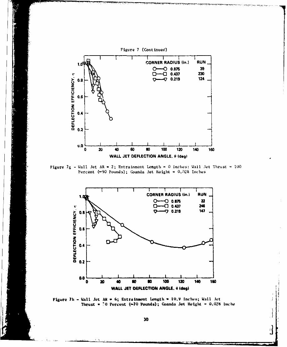
Figure 7 (Continued)II I I F Fi
CORNER RADIUS (in.) RUN.1 --- O O.M 39O--G 0.437 230
>: 0.8 - 0.219 124UzLU
~0 6w
z0U'LI
U.0
uJ.o - - 1 I I I
0 20 40 60 so 100 120 140 160
WALL JET DEFLECTION ANGLE. 0 (dog)
Figure 7g - Wall Jet AR 2; Entrainment Length a 0 Inches-. Wall Jet Thrust 100Percent (-90 Pounds); Coanda Jet Height - 0.128 Inches
1 tCORNER RADIUS (n.) RUN
O-O 0.Si zz--- 0.437 246
S0.8 9 7- 0.2119 147Uz
U. 0.6
0
UC, 0,2
S0.1 -
0.0, I I I I I I
0 20 40 so so 100 120 140 1G0
WALL JET DEFLECTION ANGLE. 0 idog)
Figure 7h - Vll Jet Ali - 6; Entrainvtot Length - 10.9 lcltwti; Will JetThruri * 70 Perceut (-70 Ioun4s)4); twda Jet tHetgiLt - 0.02h In¢wh
30
RI
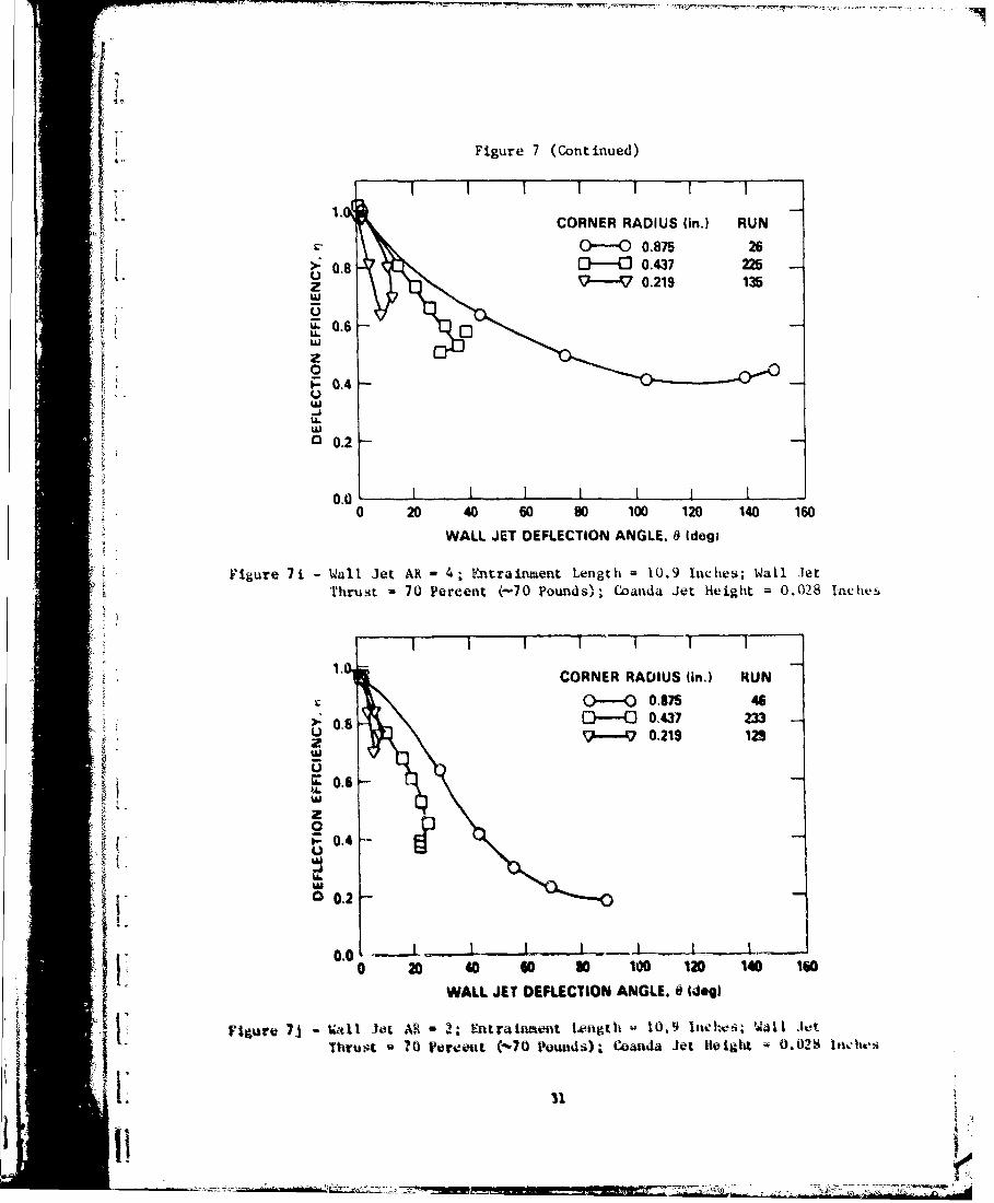
Figure 7 (Continued)
CORNER RADIUS (in.) RUN0-O 0.875 26
>: .8 0- 0.3 225U 0.219 135
z
p0.6U.)LU
LU
0.2
0.0 I0 20 40 60 80 100 120 140 160
WALL JET DEFLECTION ANGLE. 8 (dogi
Figure 7 1 -Wall Jet AR - 4; Fnt'rainment Length -1U.9 inches; Wall JetThrust 70 Percent (-70 Pounds'-, Coanda Jet Height 0.028 Inac as
1.CORNER RADIUS (in.) RUN
0-O 0.875 46
>:06D-O 0.437 2339..70.219 129
~0U.
00.
0.0
080 0 60 s 100 120 140 160
WALL JET DEFLECTION ANGLE. 0 (dog)
FiVguare 7~j - ýzd1 Jet AR, - 2; Entratament Length -10.9 Inehxzi, 14all Jet1:ThiruA ?0 Verventi (-70 petwids); Coatnda jet Height 0.02.4 loehes
31
7T-7 .7- -1
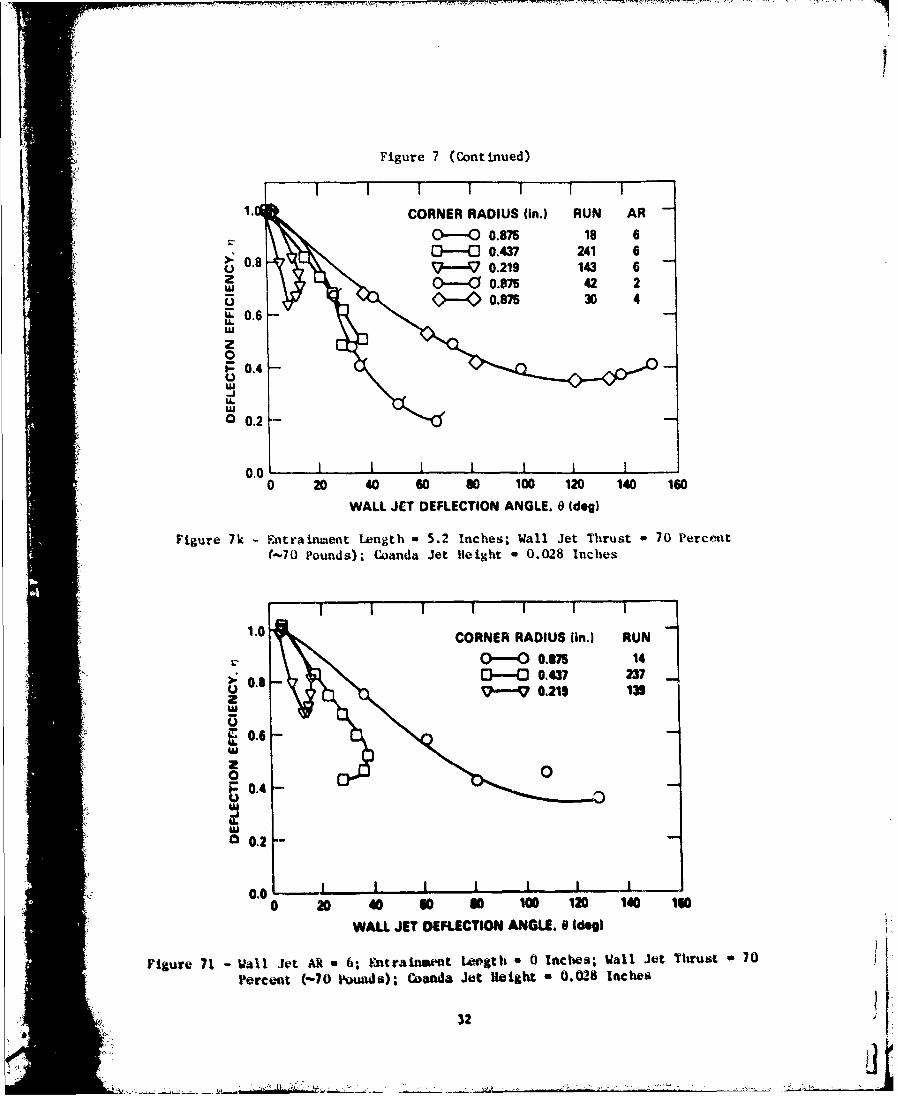
Figure 7 (Continued)
I II I I l l
CORNER RADIUS (in.) RUN AR
•-0 0.875 18 6
"• 0.8 0- 0.437 241 6ol 0.219 143 6z z . -O0.875 42 2
O .87 30 4
S0.6-
z01-0.4-U'U-J
0.'U
o0.20'
0.0 - I I I I I I
0 20 40 60 s0 100 120 140 160
WALL JET DEFLECTION ANGLE. 6 (deg)
Figure 7k - Entrainment Length - 5.2 Inches; Wall Jet Thrust - 70 Percemt(-70 Pounds); Coanda Jet Height * 0.028 Inches
I I I I I 1 /
1.0 CORNER RADIUS (in.) RUN
O---O 0.175 140.437 237
UJ."t, 0.219 131
'U
z0
0.4U
S02-
0• .o I-- - I I I I I I
0 20 o0 3o 0 100 120 140 1
WALL JET DEFLECTION ANGLE. 8 Ide d
Figure 71- VaUl Jot AR 6; 6 ntrainment Leogth a 0 Inches; Wall Jet Thrust 70
Percent (-70 Pounds); Coanda Jet Heitght 0.028 Inches
32 i
I. . ... .".- ......-. ..'.
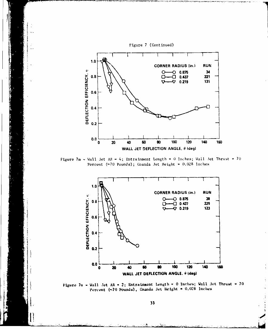
"Figure 7 (Continued)
1.0CORNER RADIUS (in.) RUN
O--O 0.875 34S0.8 O-O 0.437 221zz 9-V 0.219 131
u-0.6
zIA.0
-0.4
0 0.2
0.0 10 20 40 60 80 100 120 140 160
WALL JET DEFLECTION ANGLE. 0 (deg)
Figure 7m - Wall Jet AR 4; Entrabiment Length - 0 Inches; Wall Jet Thrust 70
Percent (-70 Pounds); Coanda Jet Height 0.028 Inches
1.0
CORNER RADIUS tin.) RUNC _____ 0. 875 38 _O- 0.808
--. 0.437 229w '-~?0.219 123
i0.6U.
0
0.0 4 ..
0 20 40 60 so 100 120 140 170
WALL JET DEFLECTION ANGLE. 0 Ideg)
Fiur 7a Wall Jet AR - 2. Entrainment Liength P 0 Inetes'. Wall Jet Thruat =70SFigure I ~1 ~
Pereent (--70 Pounds). CbaUnu Jet lieigha - 0.028 111eiwti
I 33
ii 00
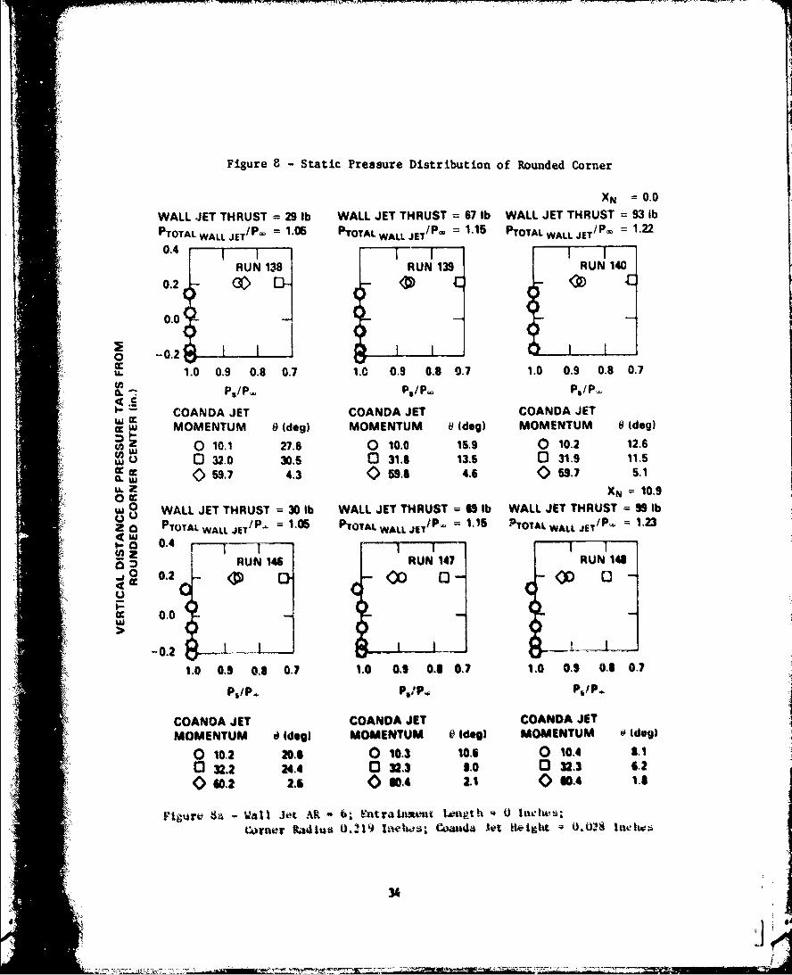
Figure 8 - Static Pressure Distribution of Rounded Corner
XN =0.0
WALL JET THRUST = 29 Ib WALL JET THRUST = 67 Ib WALL JET THRUST = 93 Ib
PTOTAL WALL JET/P-° = 1.06 PTOTAL WALL JET/P' = 1.15 PTOTAL WALL JET/pw = 1.22
0.4
RUN 138 RUN 139 RUN 140
0.2 G D- - c 4-
0.0 -
o -0.2S1.0 0.9 0.8 0.7 1.0 0.9 0.8 0.7 1.0 0.9 0.8 0.7A. -: P,/P•, ps/pi p,/P.
COANDA JET COANDA JET COANDA JET
L MOMENTUM 9 (dog) MOMENTUM 0 (dog) MOMENTUM 9 (dog)
S0 10.1 27.8 0 10.0 15.9 0 10.2 12.6S0 32.0 30.5 0 31.8 13.5 0 31.9 11.5
W 059.7 4.3 0596.8 4.6 <) 59.7 5.1XN 10.9
0 WALL JET THRUST =30 b WALL JET THRUST 6 lIb WALL JET THRUST •- Ib
a a PTOTAL WALL JET/P = 1.05 PTOTAL WALL Jp 1.16 TOTAL WALL JET/p 12
RUN 141 RUN 147 RUN 148
-O0.2
:1.0 0,9 O 0.7 1.0 0.9 0.6 0.7 1.0 0.8 0.a 0.7
P/p.p- PP. NI P.
COANOA JET COANDA JET COANDA JET
"MOMENTUM t) Ideg) MOMENTUM V (dog) MOMENTUM ( idogI
o 10.2 20,6 0 10,3 10.6 0 10.4 8.1C3 32.2 24.4 0 32.3 6.0 132.3 6.20 60.2 2.6 0 2WA LI 0 0.4 1A
Figirev 8?. Wall Jet AR~ 6 Fat ra Irment tmt Itt 0) 1ut~
34 <
do qr
II 00.9 '90 - -
0 z
0 z k0
.00 '22 ~
0 00 000~00 00
0" 4 0"
40 w-
000 0 00
4 0 k9 04"I' I F.
17 - 0 V~ rs T .00
00000J~ 0
~ 0 00 0 p-@ 0
0 130
00 80 . t Z.
0 u
-4 4 !
\00, 0
Ii I I II I
rFF~FTT41
0cc
W:~~
cc 0 Q<
0(30
0 'w a00
1-0 0
~~0
Vull MLN33 MNUMOO 030NnlOVWOWi SdVI 3VflhIMd d0 3ONVWO 1VWUM3A
36
II I
.00
00
U.1 0I,~~ [30 t
au C
v U) 'top CR
CLC
0 z- X
.00
vCCR
0 0 C-i<)K h~~0
4 ~~Q 0 40 0 ~qes
R~~10 f)N3 q3W~O3N
~~ILCulHN3 N< 0040

lilo 0
ILs
0 000
I Hl0 O e ýuC
tn
IL a
0 I0cr. <P 0 0 co
06 0 z 00
b-I Ib-4
00
00 U, C
aiz c-
%) .o~ 0 oo
1-' C) 00 03 0
0
Ipui MJN30 MUNMO (330NnlWWOW Id VI 3kinSS3Vd JO 3ONV.LSIGIO VUNMA
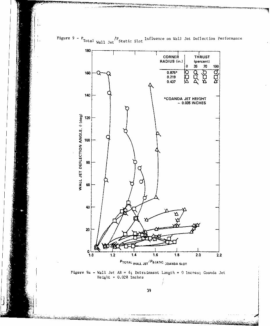
Figure 9 P Total Wal / JetPStatic Slot Influence on Wall Jet Deflection Performance
180
CORNER THRUSTRADIUS (in.) (percent)_ _ 0 35 70 100
160- 0.875* 00.219 0 f0.437 4 L
140 "*COANDA JET HEIGHT
= 0.035 INCHES
S 1 20 K
V
-j
r100z0C-)LU
w 80 -LU
0 .
40
-ti
40
1.0 1.2 1.4 1,6 1.8 2.0 2.2
PTOTAL WALL JET/ PS;ATIC ,OANDA SLOT
!Figure 9a Wall Jet AR 6; Entrainment Length 0 Incoes; Coanda JetHeight 0.028 Inches
39
':1. ,,b 0
1• ',,- .,• ,. . . , ,. :, ,, , ., ..• . ..
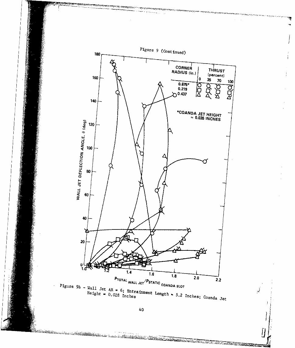
V8 Figure 9 (Continued)ISOI
160
140
*COANDA JET HEIGHT0-0035 INCHES
G~120
La;
q~100
0w-JL 80
40
.41.4
9b - Jet Oj T 6 WALL JE rýPSTATJC C A A oT2.2
Figure R 6 Entrainment Length 5.2 In h ; Co da Jp
"Height 0.028 Inches Ice;Cad e
40
~~"a
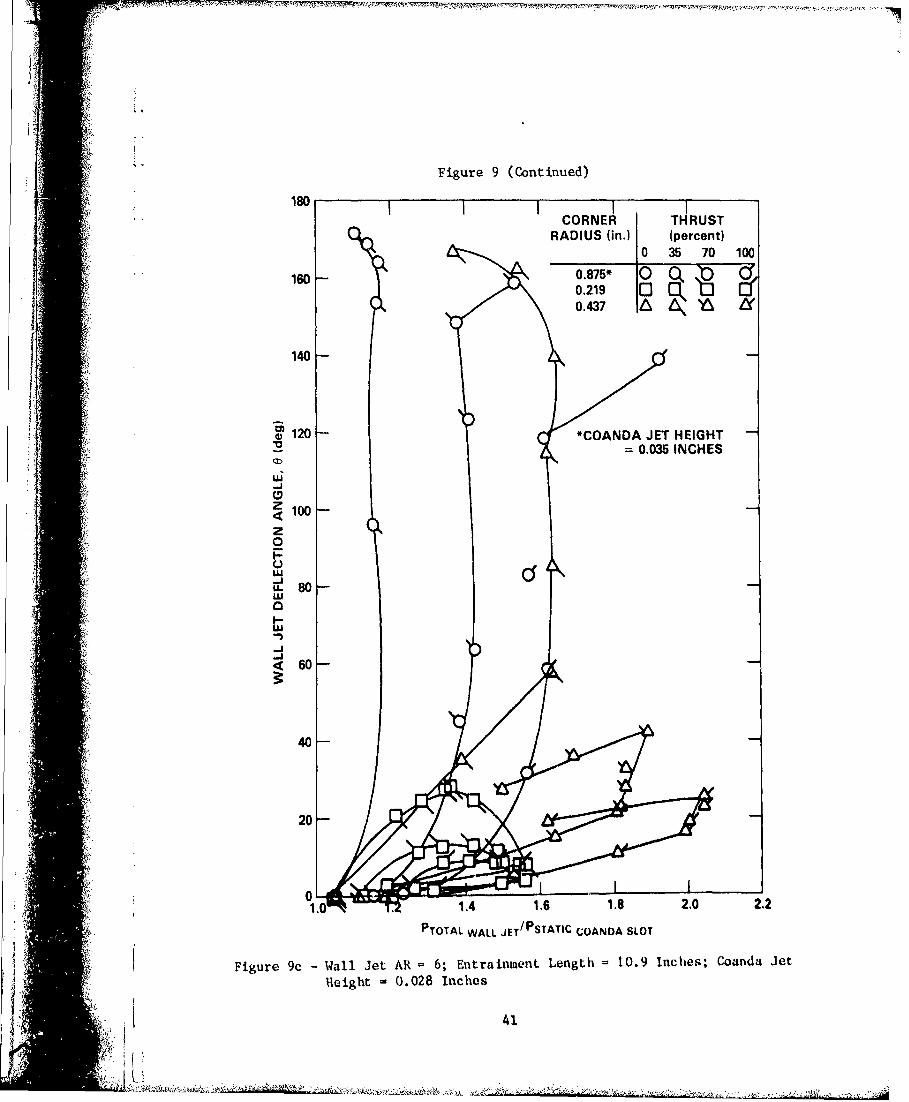
Figure 9 (Continued)
180CORNER THRUST
RADIUS (in.) (percent)10 35 70 100
160 0850.219 0 0j0.437 t
140
~120 *COANDA JET HEIGHT_ - 0.035 INCHES
z 100z0
LU80
60
40
260
40
PTOTAL WALL JET/PSTATIC COANDA SLOT
Figure 9c -Wall Jet AR 6; Entrainment Length 10.9 Inches; Coanda Jet
Height 0.028 inches
I 41
180
CORNER THRUST (percent)
RADIUS (in.)
10- 0.875 0 b Cr0.219 Cb
0.437*• 140 ~ ~~0.437 ,• )
V 120--*96 DEG ARC
( 100 -z0_.Il
60
480
a
20
601
00.0 0,5 1.0 1.1 2.0 2.5 3.0 35TOTAL PRESSURE RATIO PTOAL JET
Figure 10 - P T /P Influence on Wall Jet teflectionCoanda Jet Twall Jet
Perf ormance
(Wall Jet AR - 6; Entrainment ength- 10.9 Inchl; Coanda Jet SlotHeight - 0.014 Inclies)
42
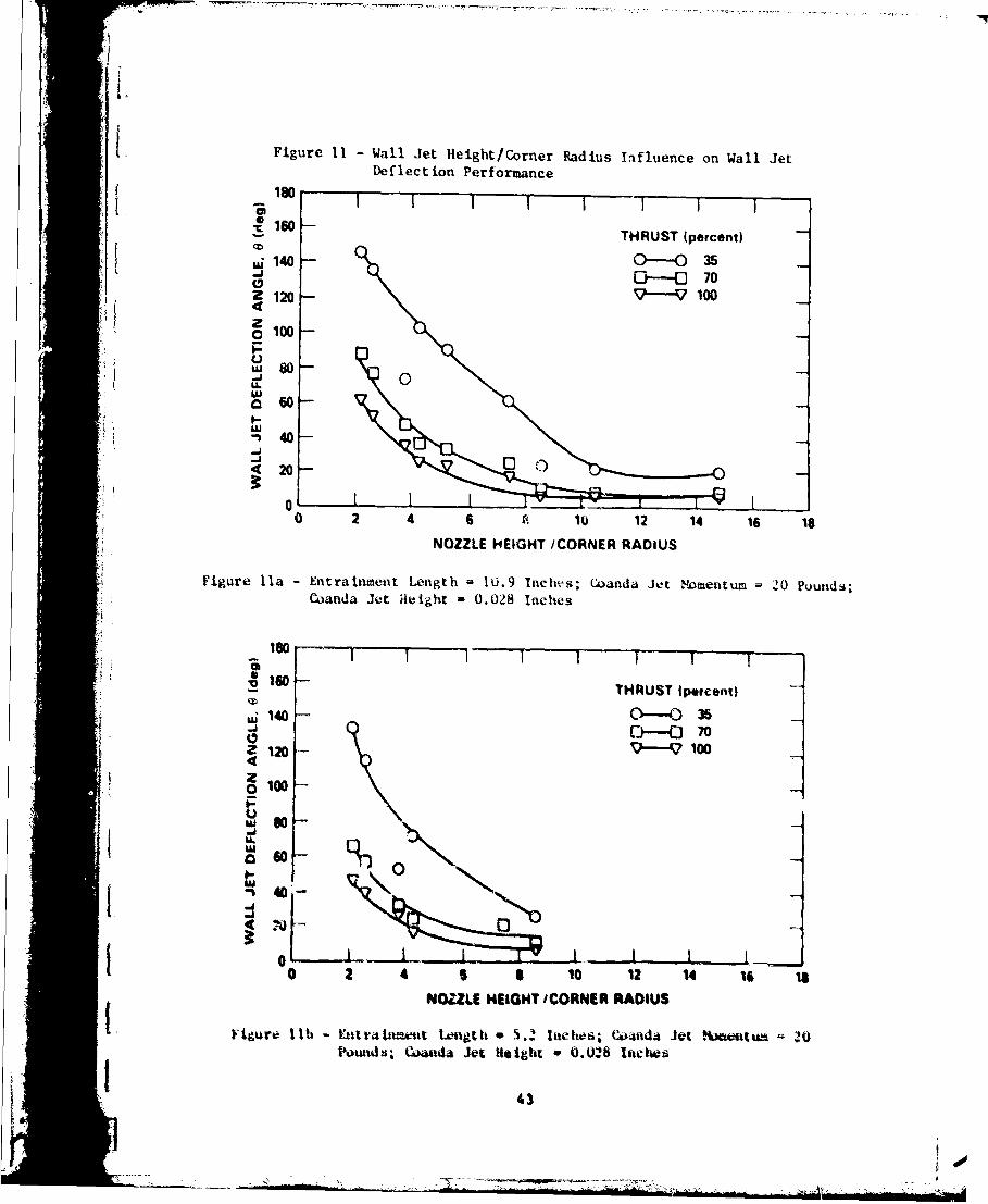
Figure 11 - Wall Jet Height/Corner Radius Influence on Wall Jet
Deflection Performance
180
S160 THRUST (percent)
"140 0-c 70
Z120 --- 100
z0100
U U8
w S60
LU-" 40
420
00 2 4 6 i 1. 12 14 16 Is
NOZZLE HEIGHT /CORNER RADIUS
Figure Ila - Entrainment Length - 10.9 Inches; Woanda Jet Nomentum 20 Pounds;Coanda Jet Height - 0.028 Inches
180-
THRUST 1percentI
zi 140 100 370-
So4 - D-- -0
109-V 100
z0100
U.
o60 Q
0 2 4 5 a 1 2 1 1 1NOZZLE HEIGHT CORNER RADIUS
Ftiure 1ib - Eatr•neut Lensgth * 5.2 * lehs; CUond4 jet .xte t , :0Powtds; C-•ada Jet Heig h O.O28 Inherw
- 7A
"'V -- '-
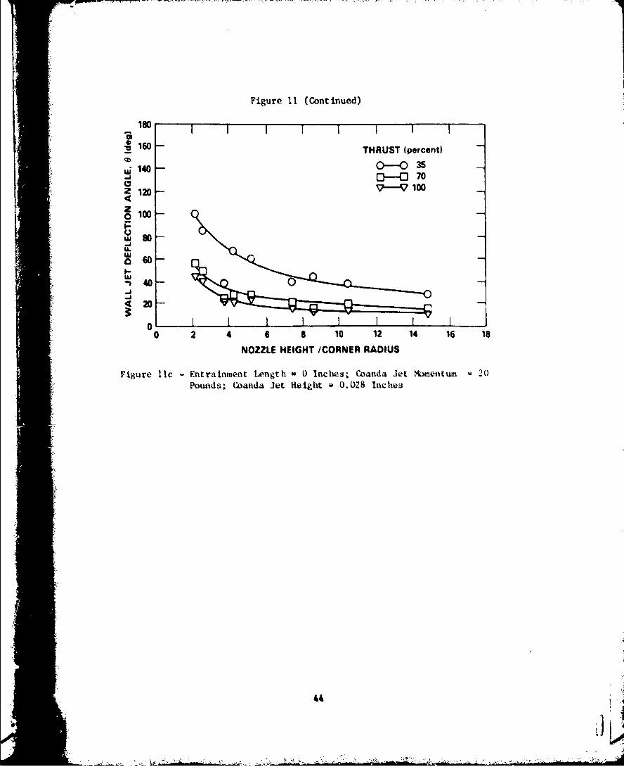
Figure 11 (Continued)
180
• 160 THRUST (percent)
0)-035140 -0- 70j C 70
a 100Z21204010 0
LU680
U.
'40
4 2
01 I0 2 4 6 S 10 12 14 16 18
NOZZLE HEIGHT /CORNER RADIUS
"Figure lic - Entriahment Length 0 Inches; Woanda Jet ,omentum 20PowAds; CWanda Jet Height 0.028 Inches
-i ' " -
ISO1
AR THRUST (percent)
160 0 35 70 100
2 0 ~C f
140 -
!120
zA4100z
0
80-
40
20
0A 0.2 0.3 0.4 0.5 0.6 0.7 0.3 0.9
CORNER RADIUS tin.)
-o ti tg~r
45
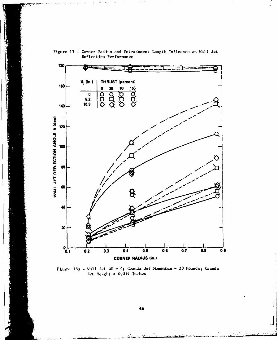
Figure 13 - Corner Radius and Entrainment Length Influence on Wall JetDeflection Performance
160- X1 (in.) THRUST (percent)0 3 70 100
;120- 11101
00
zOlz0
w /--
w60
40,0
00 0.2 0.3• 0.4 0.5 0. oo o
0. 02 0. 04 01 06 0.7 0.3 0.9
CORNER RADIUS (in.)
Figure 134 -Wall1 Jet AR w 6: c~anda Jet Mositum 20 Powi4s. Wa~ndaJet Helght 0.014 lfiws
46
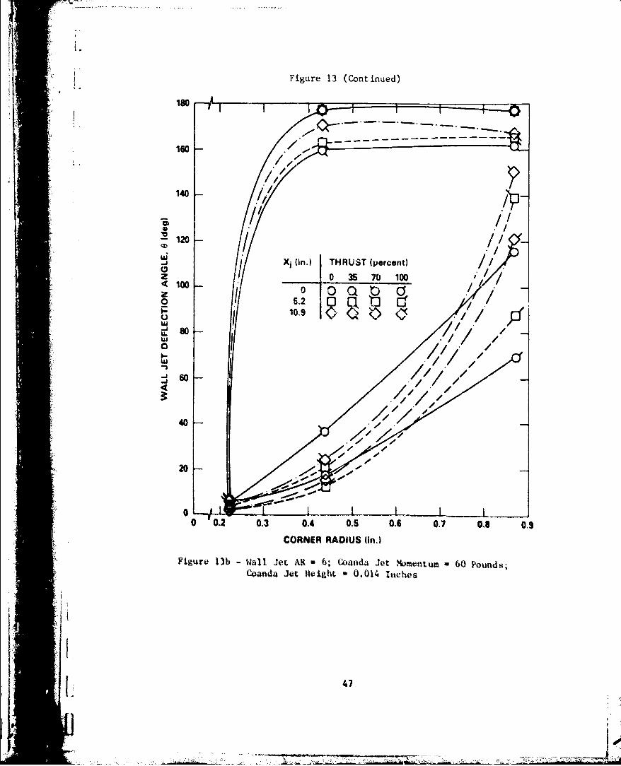
Figure 13 (Continued)
160
160 /
140
~120 1
! .i
- Xi (in.) THRUST (percent)S0 35 70 100/
4 100 0 O O C0 S',~~~~0.9 0• .//'_. 80 -U.
•8 /1
40
400
20
0 0.2 0.3 0.4 0.5 0.6 0.7 0. 0.9
CORNER RADIUS tin.)
Figure 13b - Wall Jet AR - 6; Wanda Jet MIomentum - 60 Pounda;Coanda Jet Height u 0.014 Inches
{ 471*~40
COANDA JET SPAN ITHRUST (percent)WALL JET SPAN 100
1.02.0
140 5.5
"* 120 -
u 1
-
40
30
0 10 20 30 40 w
COANDA JET MOMENTUM, MVi (ib)I
Figure 14 -Coarnda lot $panWall Jet $patI lllfl'wsiee On -~let1
(Wall Jet AR • • trainm Lengtt w . liish CQa lt4l.$&
Inewws; CWanda Jet Heigitt C (.O14 Indc s) [
48
.J