Embed Size (px)
Citation preview

COPPER PRESS FITTINGSCATALOG |

TRUSTED
3
Mueller Industries’ Streamline PRSTM press ittings are the trusted, quality solution to lameless copper joining.Streamline PRS™ is Mueller Industries’ solution for professionals choosing to join copper tubing
through the use of press technology. The company’s Streamline® brand has been the trusted name
in copper piping systems since 1930. With Streamline PRS™, this heritage of quality and reliability
is now available for contractors preferring lameless, mechanical press joining.
• 1/2” — 4” including couplings, elbows, tees, adapters, itting reducers, caps, and langes• Extensive offering of reducing tees
• Leak detection feature identiies un-crimped connections• Compatible with most common pressing tools and jaws in the market
• EPDM (Ethylene Propylene Diene Monomer) seals are factory-installed & lubricated• Packaged in common industry quantities
TABLE OF CONTENTS
BENEFITS . . . . . . . . . . . . . . . . . . . . . . . . . . . . . . . . . . . 4
SYSTEM DATA . . . . . . . . . . . . . . . . . . . . . . . . . . . . . . . 5
DIMENSIONAL DATA . . . . . . . . . . . . . . . . . . . . . . 6-15
TOOLS & JAWS . . . . . . . . . . . . . . . . . . . . . . . . . . . . 16
ENGINEERING DATA . . . . . . . . . . . . . . . . . . . . . . . . 17
INSTALLATION INSTRUCTIONS . . . . . . . . . . . . . . . 18
FEATURES . . . . . . . . . . . . . . . . . . . . . . . . . . . . . . . . . 19
TESTING WITH LEAK DETECTION . . . . . . . . . . . . 20
INSTALLATION GUIDELINES . . . . . . . . . . . . . . 21-24
FAQ'S . . . . . . . . . . . . . . . . . . . . . . . . . . . . . . . . . . 25-26
Since 1930, Mueller Industries’ Streamline® brand has been the preferred choice of professionals around the world.
Trust your copper piping system with the proven performance and reliability of Streamline® products.
• Copper Press-Joint Fittings & Flanges (PRS™)
• Copper Push-Fit Fittings (PSH™)
• Copper-Iron Braze-Joint Fittings (XHP™)
• Copper Solder-Joint Oxygen/Medical Gas Fittings
• Cast Bronze Fittings & Flanges
• Brass 45° Flare Fittings & Flanges
• Plumbing Valves
• Refrigeration Valves & Manifolds
• AC/R Protection Devices
• Copper Plumbing Tube
• Copper AC & Refrigeration Tube
• Copper Oxygen & Medical Gas Tube
• Copper Temperature Control Tube
• Copper Plastic-Coated Tube
• Copper-Iron Tube (XHP™)
• Copper Line Sets & Mini Split Line Sets
• Copper Lines Sets with Duraguard™ PE Insulation
• Copper Solder-Joint Fittings & Flanges
STREAMLINE®
THE BEST IN THE JOINT.®

4
| BENEFITS
WHY STREAMLINE PRSTM?
Press technology is growing in use as installers
seek alternative methods due to skilled labor
constraints and other factors. Its common piping
system applications today range from those in
new commercial building construction, to MRO
factory maintenance, to retroit and remodel of existing low control systems. Since the irst design was patented, there have been a number
of important evolutionary modiications. These improvements have been focused on providing
greater ease of installation and on increasing the
reliability of modern press technology.
Streamline PRSTM builds upon these
advancements and continues the quest of
improved joint design, increased holding
power, and greater reliability. With patented
design improvements and rigorous testing
requirements, we are conident that we have accomplished all of these objectives.
We understand that press tool and jaw sets are
an expensive investment for the contractor and
inventory item for wholesalers. Therefore, we
focused on improvements to the seal mechanics,
rather than the basic design of the itting. With our design, Streamline PRSTM ittings are compatible with most tools and jaws on the
market, making it easy for the end user.
With Streamline PRSTM we are conident that we have engineered a better, more reliable joint that
will withstand higher pressures and will yield
signiicantly improved anti-creep performance.
QUALITY
5
SYSTEM DATA |
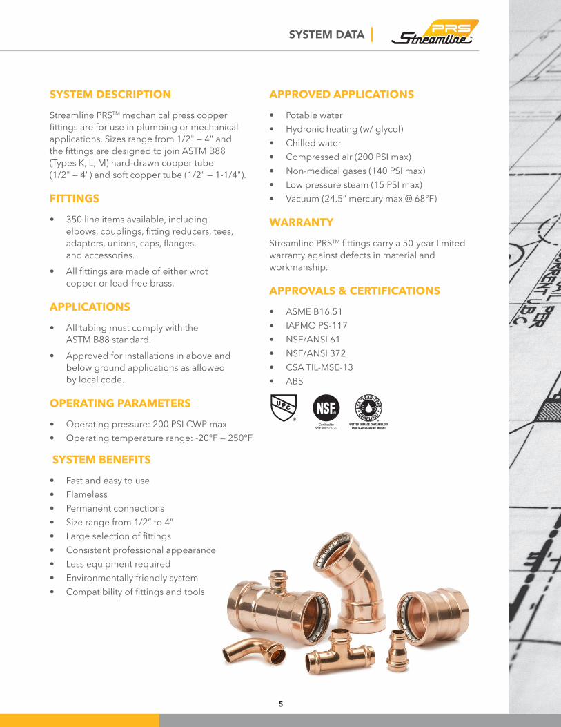
SYSTEM DESCRIPTION
Streamline PRSTM mechanical press copper
ittings are for use in plumbing or mechanical applications. Sizes range from 1/2" — 4" and
the ittings are designed to join ASTM B88 (Types K, L, M) hard-drawn copper tube (1/2" — 4") and soft copper tube (1/2" — 1-1/4").
FITTINGS
• 350 line items available, including
elbows, couplings, itting reducers, tees, adapters, unions, caps, langes, and accessories.
• All ittings are made of either wrot copper or lead-free brass.
APPLICATIONS
• All tubing must comply with the
ASTM B88 standard.
• Approved for installations in above and
below ground applications as allowed
by local code.
OPERATING PARAMETERS
• Operating pressure: 200 PSI CWP max
• Operating temperature range: -20°F — 250°F
SYSTEM BENEFITS
• Fast and easy to use
• Flameless
• Permanent connections
• Size range from 1/2” to 4”
• Large selection of ittings• Consistent professional appearance
• Less equipment required
• Environmentally friendly system
• Compatibility of ittings and tools
APPROVED APPLICATIONS
• Potable water
• Hydronic heating (w/ glycol)
• Chilled water
• Compressed air (200 PSI max)
• Non-medical gases (140 PSI max)• Low pressure steam (15 PSI max)
• Vacuum (24.5” mercury max @ 68°F)
WARRANTY
Streamline PRSTM ittings carry a 50-year limited warranty against defects in material and
workmanship.
APPROVALS & CERTIFICATIONS
• ASME B16.51
• IAPMO PS-117• NSF/ANSI 61
• NSF/ANSI 372
• CSA TIL-MSE-13• ABS
6
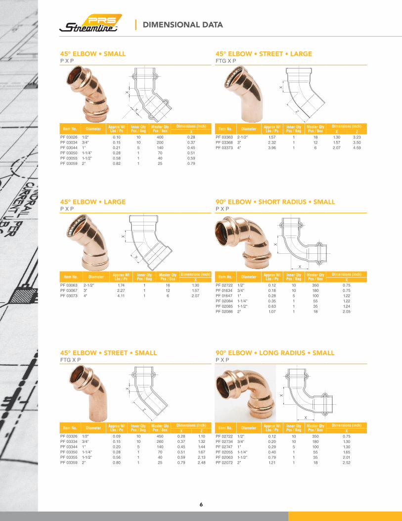
45° ELBOW • SMALLP X P
X
X
Item No. DiameterApprox WtLbs / Pc
Inner QtyPcs / Bag
Master QtyPcs / Box
Dimensions (Inch)
X
PF 03026 1/2" 0.10 10 400 0.28
PF 03034 3/4" 0.15 10 200 0.37
PF 03044 1" 0.21 5 140 0.45
PF 03050 1-1/4" 0.28 1 70 0.51
PF 03055 1-1/2" 0.58 1 40 0.59
PF 03059 2" 0.82 1 25 0.79
45° ELBOW • LARGEP X P
X
X
Item No. DiameterApprox WtLbs / Pc
Inner QtyPcs / Bag
Master QtyPcs / Box
Dimensions (Inch)
X
PF 03063 2-1/2" 1.74 1 16 1.30
PF 03067 3" 2.27 1 12 1.57
PF 03073 4" 4.11 1 6 2.07
45° ELBOW • STREET • LARGEFTG X P
X
Z
Item No. DiameterApprox WtLbs / Pc
Inner QtyPcs / Bag
Master QtyPcs / Box
Dimensions (Inch)
X Z
PF 03363 2-1/2" 1.57 1 18 1.30 3.23
PF 03368 3" 2.32 1 12 1.57 3.50
PF 03373 4" 3.96 1 6 2.07 4.59
90° ELBOW • LONG RADIUS • SMALLP X P
X
X
Item No. DiameterApprox WtLbs / Pc
Inner QtyPcs / Bag
Master QtyPcs / Box
Dimensions (Inch)
X
PF 02722 1/2" 0.12 10 350 0.75
PF 02734 3/4" 0.20 10 180 1.30
PF 02747 1" 0.29 5 100 1.30
PF 02055 1-1/4" 0.40 1 55 1.65
PF 02063 1-1/2" 0.79 1 35 2.01
PF 02072 2" 1.21 1 18 2.52
| DIMENSIONAL DATA
45° ELBOW • STREET • SMALLFTG X P
X
Z
Item No. DiameterApprox WtLbs / Pc
Inner QtyPcs / Bag
Master QtyPcs / Box
Dimensions (Inch)
X Z
PF 03326 1/2" 0.09 10 450 0.28 1.10
PF 03334 3/4" 0.15 10 260 0.37 1.32
PF 03344 1" 0.20 5 140 0.45 1.44
PF 03350 1-1/4" 0.28 1 70 0.51 1.67
PF 03355 1-1/2" 0.56 1 40 0.59 2.13
PF 03359 2" 0.80 1 25 0.79 2.48
90° ELBOW • SHORT RADIUS • SMALLP X P
X
X
Item No. DiameterApprox WtLbs / Pc
Inner QtyPcs / Bag
Master QtyPcs / Box
Dimensions (Inch)
X
PF 02722 1/2" 0.12 10 350 0.75
PF 01634 3/4" 0.18 10 180 0.75
PF 01647 1" 0.28 5 100 1.22
PF 02084 1-1/4" 0.35 1 55 1.22
PF 02085 1-1/2" 0.63 1 35 1.24
PF 02086 2" 1.07 1 18 2.05
7
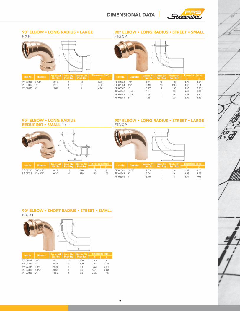
90° ELBOW • LONG RADIUS • LARGEP X P
X
X
Item No. DiameterApprox WtLbs / Pc
Inner QtyPcs / Bag
Master QtyPcs / Box
Dimensions (Inch)
X
PF 02082 2-1/2" 2.10 1 12 2.99
PF 02092 3" 2.10 1 9 3.58
PF 02095 4" 5.62 1 4 4.74
90° ELBOW • LONG RADIUSREDUCING • SMALL P X P
X
X1
Item No. DiameterApprox WtLbs / Pc
Inner QtyPcs / Bag
Master QtyPcs / Box
Dimensions (Inch)
X X1
PF 02736 3/4" x 1/2" 0.19 15 240 1.02 1.26
PF 02749 1" x 3/4" 0.30 10 120 1.30 1.56
90° ELBOW • LONG RADIUS • STREET • SMALLFTG X P
X
Z
Item No. DiameterApprox WtLbs / Pc
Inner QtyPcs / Bag
Master QtyPcs / Box
Dimensions (Inch)
X Z
PF 02822 1/2" 0.11 10 400 0.75 1.57
PF 02834 3/4" 0.19 10 200 1.02 2.01
PF 02847 1" 0.27 5 100 1.30 2.28
PF 02350 1-1/4" 0.41 1 55 1.65 2.83
PF 02355 1-1/2" 0.76 1 35 2.01 3.52
PF 02359 2" 1.16 1 20 2.52 4.15
90° ELBOW • LONG RADIUS • STREET • LARGEFTG X P
Z
X
Item No. DiameterApprox WtLbs / Pc
Inner QtyPcs / Bag
Master QtyPcs / Box
Dimensions (Inch)
X Z
PF 02363 2-1/2" 2.05 1 14 2.99 5.00
PF 02368 3" 3.04 1 9 3.58 5.58
PF 02395 4" 5.70 1 4 4.74 7.05
DIMENSIONAL DATA |
90° ELBOW • SHORT RADIUS • STREET • SMALLFTG X P
X
Z
Item No. DiameterApprox WtLbs / Pc
Inner QtyPcs / Bag
Master QtyPcs / Box
Dimensions (Inch)
X Z
PF 01654 3/4" 0.16 10 200 0.75 2.01
PF 02344 1" 0.27 5 100 1.22 2.28
PF 02384 1-1/4" 0.35 1 55 1.22 2.84
PF 02385 1-1/2" 0.64 1 35 1.24 3.52
PF 02386 2" 1.05 1 20 2.05 4.15

8
ADAPTER • FEMALE • SMALLP X FPT
A
Item No. DiameterApprox WtLbs / Pc
Inner QtyPcs / Bag
Master QtyPcs / Box
Dimensions (Inch)
A
PF 01231 1/2" 0.10 10 300 0.70
PF 01246 3/4" 0.17 10 150 0.87
PF 01263 1" 0.25 10 180 0.89
PF 01271 1-1/4" 0.35 1 80 0.96
PF 01279 1-1/2" 0.53 1 55 1.02
PF 01287 2" 0.78 1 40 1.06
ADAPTER • FEMALE • LARGEP X FPT
A
Item No. DiameterApprox WtLbs / Pc
Inner QtyPcs / Bag
Master QtyPcs / Box
Dimensions (Inch)
A
PF 01296 2-1/2" 1.25 1 36 1.30
PF 01297 3" 1.85 1 24 1.54
ADAPTER • FEMALE • REDUCING • SMALLP X FPT
A
Item No. DiameterApprox WtLbs / Pc
Inner QtyPcs / Bag
Master QtyPcs / Box
Dimensions (Inch)
A
PF 01232 1/2" x 3/8" 0.07 10 300 0.53
PF 01230 1/2" x 3/4" 0.15 10 180 0.98
PF 01247 3/4" x 1/2" 0.17 10 180 0.71
PF 01265 1" x 1/2" 0.29 10 120 0.73
PF 01264 1" x 3/4" 0.22 10 200 0.71
PF 01261 1" x 1-1/4" 0.46 10 60 1.40
PF 01272 1-1/4" x 1" 0.29 1 100 0.85
PF 01270 1-1/4" x 1-1/2" 0.62 1 70 1.56
PF 01280 1-1/2" x 1-1/4" 0.46 1 70 0.94
| DIMENSIONAL DATA
90° ELBOW • DROP EAR • SMALLP X FPT
L3 L2
A
L
Item No. DiameterApprox WtLbs / Pc
Inner QtyPcs / Bag
Master QtyPcs / Box
Dimensions (Inch)
A L L2 L3
PF 01508 1/2" 0.25 5 100 0.88 1.63 0.76 0.75
PF 02581 3/4" 0.44 5 60 1.09 2.00 1.25 0.87
90° ELBOW • FEMALE • SMALLP X FPT
X
L
Item No. DiameterApprox WtLbs / Pc
Inner QtyPcs / Bag
Master QtyPcs / Box
Dimensions (Inch)
L X
PF 01507 1/2" 0.23 5 200 2.65 0.75
PF 01532 3/4" 0.37 5 120 3.24 1.02
PF 01559 1" 0.55 1 60 3.57 1.30
PF 01594 1-1/4" 0.74 1 45 4.13 1.65
PF 01632 1-1/2" 1.34 1 25 4.95 2.01
PF 01680 2" 1.98 1 15 5.67 2.52
90° ELBOW • MALE • SMALLP X MPT
L
X
Item No. DiameterApprox WtLbs / Pc
Inner QtyPcs / Bag
Master QtyPcs / Box
Dimensions (Inch)
L X
PF 01506 1/2" 0.23 5 200 2.82 0.75
PF 01531 3/4" 0.39 5 120 3.36 1.02
PF 01558 1" 0.60 1 65 3.76 1.30
PF 01593 1-1/4" 0.81 1 45 4.41 1.65
PF 01631 1-1/2" 1.42 1 25 5.22 2.01
PF 01679 2" 2.12 1 15 5.98 2.52
9
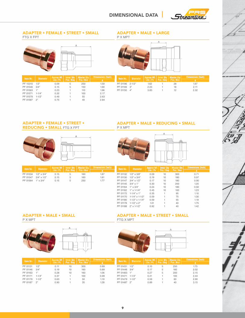
ADAPTER • FEMALE • STREET • SMALLFTG X FPT
A
Item No. DiameterApprox WtLbs / Pc
Inner QtyPcs / Bag
Master QtyPcs / Box
Dimensions (Inch)
A
PF 15310 1/2" 0.09 5 250 1.59
PF 01546 3/4" 0.15 5 150 1.90
PF 01563 1" 0.23 1 110 1.96
PF 01571 1-1/4" 0.32 1 100 2.17
PF 01579 1-1/2" 0.49 1 55 2.63
PF 01587 2" 0.75 1 40 2.84
ADAPTER • FEMALE • STREET • REDUCING • SMALL FTG X FPT
A
Item No. DiameterApprox WtLbs / Pc
Inner QtyPcs / Bag
Master QtyPcs / Box
Dimensions (Inch)
A
PF 01534 1/2" x 3/4" 0.15 5 160 1.87
PF 01547 3/4" x 1/2" 0.15 5 160 1.81
PF 01564 1" x 3/4" 0.15 5 250 1.77
ADAPTER • MALE • SMALLP X MPT
A
Item No. DiameterApprox WtLbs / Pc
Inner QtyPcs / Bag
Master QtyPcs / Box
Dimensions (Inch)
A
PF 01131 1/2" 0.11 10 300 0.89
PF 01146 3/4" 0.19 10 160 0.89
PF 01163 1" 0.28 10 160 1.06
PF 01171 1-1/4" 0.37 1 100 0.99
PF 01179 1-1/2" 0.63 1 50 1.19
PF 01187 2" 0.90 1 35 1.28
ADAPTER • MALE • LARGEP X MPT
Item No. DiameterApprox WtLbs / Pc
Inner QtyPcs / Bag
Master QtyPcs / Box
Dimensions (Inch)
A
PF 01196 2-1/2" 1.62 1 28 1.97
PF 01199 3" 2.23 1 18 2.11
PF 01150 4" 3.83 1 12 2.32
ADAPTER • MALE • REDUCING • SMALLP X MPT
A
Item No. DiameterApprox WtLbs / Pc
Inner QtyPcs / Bag
Master QtyPcs / Box
Dimensions (Inch)
A
PF 01132 1/2" x 3/8" 0.09 10 300 0.71
PF 01130 1/2" x 3/4" 0.19 10 180 0.97
PF 01147 3/4" x 1/2" 0.17 10 180 0.90
PF 01145 3/4" x 1" 0.30 10 200 1.20
PF 01164 1" x 3/4" 0.24 10 180 0.92
PF 01162 1" x 1-1/4" 0.45 10 100 1.23
PF 01172 1-1/4" x 1" 0.35 1 95 1.10
PF 01170 1-1/4" x 1-1/2" 0.59 1 75 1.30
PF 01180 1-1/2" x 1-1/4" 0.59 1 55 1.19
PF 01178 1-1/2" x 2" 1.01 1 40 1.75
PF 01188 2" x 1-1/2" 0.92 1 40 1.42
ADAPTER • MALE • STREET • SMALLFTG X MPT
A
Item No. DiameterApprox WtLbs / Pc
Inner QtyPcs / Bag
Master QtyPcs / Box
Dimensions (Inch)
A
PF 01431 1/2" 0.10 5 250 1.75
PF 01446 3/4" 0.17 5 160 2.02
PF 01463 1" 0.27 5 200 2.15
PF 01471 1-1/4" 0.41 1 100 2.44
PF 01479 1-1/2" 0.59 1 60 2.90
PF 01487 2" 0.89 1 40 3.15
A
DIMENSIONAL DATA |
10
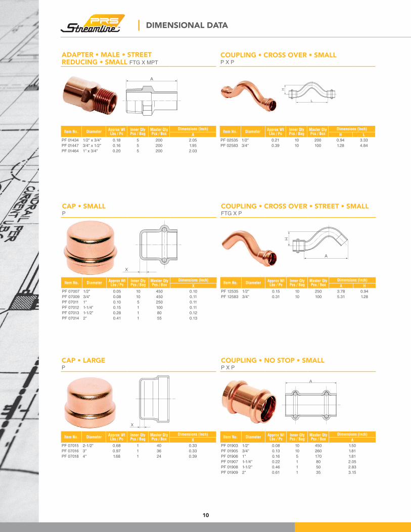
COUPLING • CROSS OVER • SMALLP X P
L
H
Item No. DiameterApprox WtLbs / Pc
Inner QtyPcs / Bag
Master QtyPcs / Box
Dimensions (Inch)
H L
PF 02535 1/2" 0.21 10 200 0.94 3.33
PF 02583 3/4" 0.39 10 100 1.28 4.84
COUPLING • CROSS OVER • STREET • SMALLFTG X P
Item No. DiameterApprox WtLbs / Pc
Inner QtyPcs / Bag
Master QtyPcs / Box
Dimensions (Inch)
A H
PF 12535 1/2" 0.15 10 250 3.78 0.94
PF 12583 3/4" 0.31 10 100 5.31 1.28
COUPLING • NO STOP • SMALLP X P
A
Item No. DiameterApprox WtLbs / Pc
Inner QtyPcs / Bag
Master QtyPcs / Box
Dimensions (Inch)
A
PF 01903 1/2" 0.08 10 450 1.50
PF 01905 3/4" 0.13 10 260 1.81
PF 01906 1" 0.16 5 170 1.81
PF 01907 1-1/4" 0.22 1 80 2.05
PF 01908 1-1/2" 0.46 1 50 2.83
PF 01909 2" 0.61 1 35 3.15
H
A
| DIMENSIONAL DATA
ADAPTER • MALE • STREETREDUCING • SMALL FTG X MPT
A
Item No. DiameterApprox WtLbs / Pc
Inner QtyPcs / Bag
Master QtyPcs / Box
Dimensions (Inch)
A
PF 01434 1/2" x 3/4" 0.18 5 200 2.05
PF 01447 3/4" x 1/2" 0.16 5 200 1.95
PF 01464 1" x 3/4" 0.20 5 200 2.03
CAP • SMALLP
X
Item No. DiameterApprox WtLbs / Pc
Inner QtyPcs / Bag
Master QtyPcs / Box
Dimensions (Inch)
X
PF 07007 1/2" 0.05 10 450 0.10
PF 07009 3/4" 0.08 10 450 0.11
PF 07011 1" 0.10 5 250 0.11
PF 07012 1-1/4" 0.15 1 100 0.11
PF 07013 1-1/2" 0.28 1 80 0.12
PF 07014 2" 0.41 1 55 0.13
CAP • LARGEP
Item No. DiameterApprox WtLbs / Pc
Inner QtyPcs / Bag
Master QtyPcs / Box
Dimensions (Inch)
X
PF 07015 2-1/2" 0.68 1 40 0.33
PF 07016 3" 0.97 1 36 0.33
PF 07018 4" 1.68 1 24 0.39
X
11
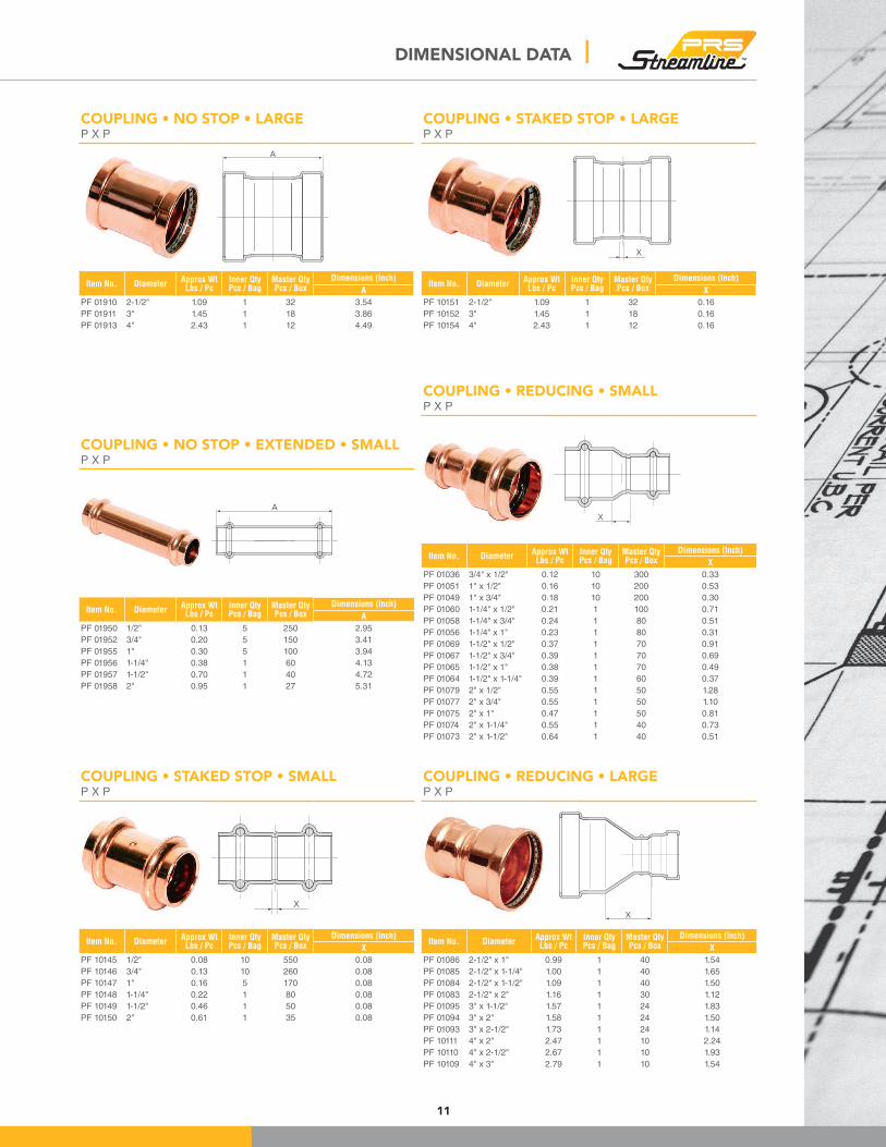
COUPLING • NO STOP • LARGEP X P
Item No. DiameterApprox WtLbs / Pc
Inner QtyPcs / Bag
Master QtyPcs / Box
Dimensions (Inch)
A
PF 01910 2-1/2" 1.09 1 32 3.54
PF 01911 3" 1.45 1 18 3.86
PF 01913 4" 2.43 1 12 4.49
COUPLING • NO STOP • EXTENDED • SMALLP X P
A
Item No. DiameterApprox WtLbs / Pc
Inner QtyPcs / Bag
Master QtyPcs / Box
Dimensions (Inch)
A
PF 01950 1/2" 0.13 5 250 2.95
PF 01952 3/4" 0.20 5 150 3.41
PF 01955 1" 0.30 5 100 3.94
PF 01956 1-1/4" 0.38 1 60 4.13
PF 01957 1-1/2" 0.70 1 40 4.72
PF 01958 2" 0.95 1 27 5.31
COUPLING • STAKED STOP • SMALLP X P
X
Item No. DiameterApprox WtLbs / Pc
Inner QtyPcs / Bag
Master QtyPcs / Box
Dimensions (Inch)
X
PF 10145 1/2" 0.08 10 550 0.08
PF 10146 3/4" 0.13 10 260 0.08
PF 10147 1" 0.16 5 170 0.08
PF 10148 1-1/4" 0.22 1 80 0.08
PF 10149 1-1/2" 0.46 1 50 0.08
PF 10150 2" 0.61 1 35 0.08
COUPLING • STAKED STOP • LARGEP X P
Item No. DiameterApprox WtLbs / Pc
Inner QtyPcs / Bag
Master QtyPcs / Box
Dimensions (Inch)
X
PF 10151 2-1/2" 1.09 1 32 0.16
PF 10152 3" 1.45 1 18 0.16
PF 10154 4" 2.43 1 12 0.16
COUPLING • REDUCING • SMALLP X P
X
Item No. DiameterApprox WtLbs / Pc
Inner QtyPcs / Bag
Master QtyPcs / Box
Dimensions (Inch)
X
PF 01036 3/4" x 1/2" 0.12 10 300 0.33
PF 01051 1" x 1/2" 0.16 10 200 0.53
PF 01049 1" x 3/4" 0.18 10 200 0.30
PF 01060 1-1/4" x 1/2" 0.21 1 100 0.71
PF 01058 1-1/4" x 3/4" 0.24 1 80 0.51
PF 01056 1-1/4" x 1" 0.23 1 80 0.31
PF 01069 1-1/2" x 1/2" 0.37 1 70 0.91
PF 01067 1-1/2" x 3/4" 0.39 1 70 0.69
PF 01065 1-1/2" x 1" 0.38 1 70 0.49
PF 01064 1-1/2" x 1-1/4" 0.39 1 60 0.37
PF 01079 2" x 1/2" 0.55 1 50 1.28
PF 01077 2" x 3/4" 0.55 1 50 1.10
PF 01075 2" x 1" 0.47 1 50 0.81
PF 01074 2" x 1-1/4" 0.55 1 40 0.73
PF 01073 2" x 1-1/2" 0.64 1 40 0.51
COUPLING • REDUCING • LARGEP X P
X
Item No. DiameterApprox WtLbs / Pc
Inner QtyPcs / Bag
Master QtyPcs / Box
Dimensions (Inch)
X
PF 01086 2-1/2" x 1" 0.99 1 40 1.54
PF 01085 2-1/2" x 1-1/4" 1.00 1 40 1.65
PF 01084 2-1/2" x 1-1/2" 1.09 1 40 1.50
PF 01083 2-1/2" x 2" 1.16 1 30 1.12
PF 01095 3" x 1-1/2" 1.57 1 24 1.83
PF 01094 3" x 2" 1.58 1 24 1.50
PF 01093 3" x 2-1/2" 1.73 1 24 1.14
PF 10111 4" x 2" 2.47 1 10 2.24
PF 10110 4" x 2-1/2" 2.67 1 10 1.93
PF 10109 4" x 3" 2.79 1 10 1.54
A
X
DIMENSIONAL DATA |
12
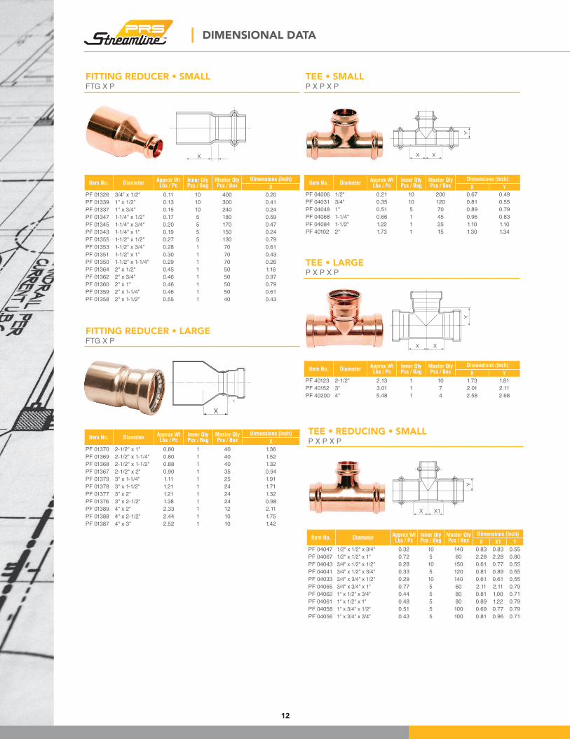
TEE • SMALLP X P X P
Y
X X
Item No. DiameterApprox WtLbs / Pc
Inner QtyPcs / Bag
Master QtyPcs / Box
Dimensions (Inch)
X Y
PF 04006 1/2" 0.21 10 200 0.67 0.49
PF 04031 3/4" 0.35 10 120 0.81 0.55
PF 04048 1" 0.51 5 70 0.89 0.79
PF 04068 1-1/4" 0.66 1 45 0.96 0.83
PF 04084 1-1/2" 1.22 1 25 1.10 1.10
PF 40102 2" 1.73 1 15 1.30 1.34
TEE • LARGEP X P X P
Y
XX
Item No. DiameterApprox WtLbs / Pc
Inner QtyPcs / Bag
Master QtyPcs / Box
Dimensions (Inch)
X Y
PF 40123 2-1/2" 2.13 1 10 1.73 1.81
PF 40152 3" 3.01 1 7 2.01 2.11
PF 40200 4" 5.48 1 4 2.58 2.68
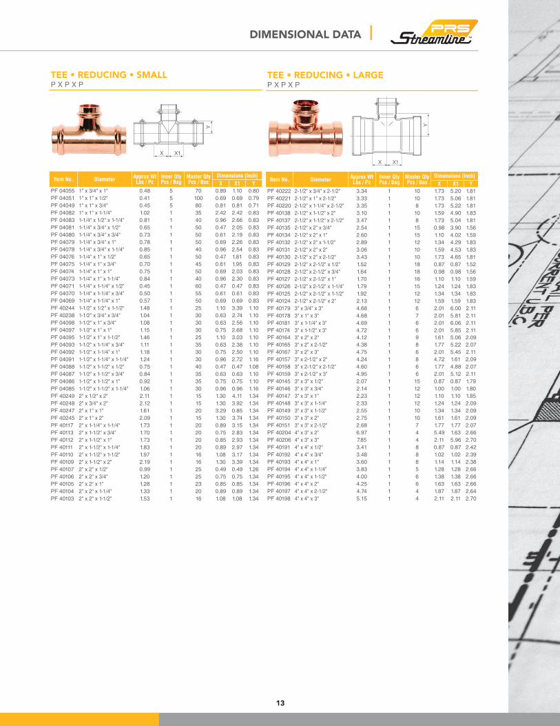
TEE • REDUCING • SMALLP X P X P
Y
X X1
Item No. DiameterApprox WtLbs / Pc
Inner QtyPcs / Bag
Master QtyPcs / Box
Dimensions (Inch)
X X1 Y
PF 04047 1/2" x 1/2" x 3/4" 0.32 10 140 0.83 0.83 0.55
PF 04067 1/2" x 1/2" x 1" 0.72 5 60 2.28 2.28 0.80
PF 04043 3/4" x 1/2" x 1/2" 0.28 10 150 0.61 0.77 0.55
PF 04041 3/4" x 1/2" x 3/4" 0.33 5 120 0.81 0.89 0.55
PF 04033 3/4" x 3/4" x 1/2" 0.29 10 140 0.61 0.61 0.55
PF 04065 3/4" x 3/4" x 1" 0.77 5 60 2.11 2.11 0.79
PF 04062 1" x 1/2" x 3/4" 0.44 5 80 0.81 1.00 0.71
PF 04061 1" x 1/2" x 1" 0.48 5 80 0.89 1.22 0.79
PF 04058 1" x 3/4" x 1/2" 0.51 5 100 0.69 0.77 0.79
PF 04056 1" x 3/4" x 3/4" 0.43 5 100 0.81 0.96 0.71
| DIMENSIONAL DATA
FITTING REDUCER • SMALLFTG X P
X
Item No. DiameterApprox WtLbs / Pc
Inner QtyPcs / Bag
Master QtyPcs / Box
Dimensions (Inch)
X
PF 01326 3/4" x 1/2" 0.11 10 400 0.20
PF 01339 1" x 1/2" 0.13 10 300 0.41
PF 01337 1" x 3/4" 0.15 10 240 0.24
PF 01347 1-1/4" x 1/2" 0.17 5 180 0.59
PF 01345 1-1/4" x 3/4" 0.20 5 170 0.47
PF 01343 1-1/4" x 1" 0.19 5 150 0.24
PF 01355 1-1/2" x 1/2" 0.27 5 130 0.79
PF 01353 1-1/2" x 3/4" 0.28 1 70 0.61
PF 01351 1-1/2" x 1" 0.30 1 70 0.43
PF 01350 1-1/2" x 1-1/4" 0.29 1 70 0.26
PF 01364 2" x 1/2" 0.45 1 50 1.16
PF 01362 2" x 3/4" 0.46 1 50 0.97
PF 01360 2" x 1" 0.46 1 50 0.79
PF 01359 2" x 1-1/4" 0.46 1 50 0.61
PF 01358 2" x 1-1/2" 0.55 1 40 0.43
FITTING REDUCER • LARGEFTG X P
X
X
Item No. DiameterApprox WtLbs / Pc
Inner QtyPcs / Bag
Master QtyPcs / Box
Dimensions (Inch)
X
PF 01370 2-1/2" x 1" 0.80 1 40 1.36
PF 01369 2-1/2" x 1-1/4" 0.80 1 40 1.52
PF 01368 2-1/2" x 1-1/2" 0.88 1 40 1.32
PF 01367 2-1/2" x 2" 0.90 1 35 0.94
PF 01379 3" x 1-1/4" 1.11 1 25 1.91
PF 01378 3" x 1-1/2" 1.21 1 24 1.71
PF 01377 3" x 2" 1.21 1 24 1.32
PF 01376 3" x 2-1/2" 1.38 1 24 0.98
PF 01389 4" x 2" 2.33 1 12 2.11
PF 01388 4" x 2-1/2" 2.44 1 10 1.75
PF 01387 4" x 3" 2.52 1 10 1.42
13
TEE • REDUCING • SMALLP X P X P
Y
X X1
Item No. DiameterApprox WtLbs / Pc
Inner QtyPcs / Bag
Master QtyPcs / Box
Dimensions (Inch)
X X1 Y
PF 04055 1" x 3/4" x 1" 0.48 5 70 0.89 1.10 0.80
PF 04051 1" x 1" x 1/2" 0.41 5 100 0.69 0.69 0.79
PF 04049 1" x 1" x 3/4" 0.45 5 80 0.81 0.81 0.71
PF 04082 1" x 1" x 1-1/4" 1.02 1 35 2.42 2.42 0.83
PF 04083 1-1/4" x 1/2" x 1-1/4" 0.81 1 40 0.96 2.66 0.83
PF 04081 1-1/4" x 3/4" x 1/2" 0.65 1 50 0.47 2.05 0.83
PF 04080 1-1/4" x 3/4" x 3/4" 0.73 1 50 0.61 2.19 0.83
PF 04079 1-1/4" x 3/4" x 1" 0.78 1 50 0.69 2.26 0.83
PF 04078 1-1/4" x 3/4" x 1-1/4" 0.85 1 40 0.96 2.54 0.83
PF 04076 1-1/4" x 1" x 1/2" 0.65 1 50 0.47 1.81 0.83
PF 04075 1-1/4" x 1" x 3/4" 0.70 1 45 0.61 1.95 0.83
PF 04074 1-1/4" x 1" x 1" 0.75 1 50 0.69 2.03 0.83
PF 04073 1-1/4" x 1" x 1-1/4" 0.84 1 40 0.96 2.30 0.83
PF 04071 1-1/4" x 1-1/4" x 1/2" 0.45 1 60 0.47 0.47 0.83
PF 04070 1-1/4" x 1-1/4" x 3/4" 0.50 1 55 0.61 0.61 0.83
PF 04069 1-1/4" x 1-1/4" x 1" 0.57 1 50 0.69 0.69 0.83
PF 40244 1-1/2" x 1/2" x 1-1/2" 1.48 1 25 1.10 3.39 1.10
PF 40238 1-1/2" x 3/4" x 3/4" 1.04 1 30 0.63 2.74 1.10
PF 04098 1-1/2" x 1" x 3/4" 1.08 1 30 0.63 2.56 1.10
PF 04097 1-1/2" x 1" x 1" 1.15 1 30 0.75 2.68 1.10
PF 04095 1-1/2" x 1" x 1-1/2" 1.46 1 25 1.10 3.03 1.10
PF 04093 1-1/2" x 1-1/4" x 3/4" 1.11 1 35 0.63 2.38 1.10
PF 04092 1-1/2" x 1-1/4" x 1" 1.18 1 30 0.75 2.50 1.10
PF 04091 1-1/2" x 1-1/4" x 1-1/4" 1.24 1 30 0.96 2.72 1.16
PF 04088 1-1/2" x 1-1/2" x 1/2" 0.75 1 40 0.47 0.47 1.08
PF 04087 1-1/2" x 1-1/2" x 3/4" 0.84 1 35 0.63 0.63 1.10
PF 04086 1-1/2" x 1-1/2" x 1" 0.92 1 35 0.75 0.75 1.10
PF 04085 1-1/2" x 1-1/2" x 1-1/4" 1.06 1 30 0.96 0.96 1.16
PF 40249 2" x 1/2" x 2" 2.11 1 15 1.30 4.11 1.34
PF 40248 2" x 3/4" x 2" 2.12 1 15 1.30 3.92 1.34
PF 40247 2" x 1" x 1" 1.61 1 20 3.29 0.85 1.34
PF 40245 2" x 1" x 2" 2.09 1 15 1.30 3.74 1.34
PF 40117 2" x 1-1/4" x 1-1/4" 1.73 1 20 0.89 3.15 1.34
PF 40113 2" x 1-1/2" x 3/4" 1.70 1 20 0.75 2.83 1.34
PF 40112 2" x 1-1/2" x 1" 1.73 1 20 0.85 2.93 1.34
PF 40111 2" x 1-1/2" x 1-1/4" 1.83 1 20 0.89 2.97 1.34
PF 40110 2" x 1-1/2" x 1-1/2" 1.97 1 16 1.08 3.17 1.34
PF 40109 2" x 1-1/2" x 2" 2.19 1 16 1.30 3.39 1.34
PF 40107 2" x 2" x 1/2" 0.99 1 25 0.49 0.49 1.26
PF 40106 2" x 2" x 3/4" 1.20 1 25 0.75 0.75 1.34
PF 40105 2" x 2" x 1" 1.28 1 23 0.85 0.85 1.34
PF 40104 2" x 2" x 1-1/4" 1.33 1 20 0.89 0.89 1.34
PF 40103 2" x 2" x 1-1/2" 1.53 1 16 1.08 1.08 1.34
TEE • REDUCING • LARGEP X P X P
Y
X1X
Item No. DiameterApprox WtLbs / Pc
Inner QtyPcs / Bag
Master QtyPcs / Box
Dimensions (Inch)
X X1 Y
PF 40222 2-1/2" x 3/4" x 2-1/2" 3.34 1 10 1.73 5.20 1.81
PF 40221 2-1/2" x 1" x 2-1/2" 3.33 1 10 1.73 5.06 1.81
PF 40220 2-1/2" x 1-1/4" x 2-1/2" 3.35 1 8 1.73 5.22 1.81
PF 40138 2-1/2" x 1-1/2" x 2" 3.10 1 10 1.59 4.90 1.83
PF 40137 2-1/2" x 1-1/2" x 2-1/2" 3.47 1 8 1.73 5.04 1.81
PF 40135 2-1/2" x 2" x 3/4" 2.54 1 15 0.98 3.90 1.56
PF 40134 2-1/2" x 2" x 1" 2.60 1 15 1.10 4.02 1.59
PF 40132 2-1/2" x 2" x 1-1/2" 2.89 1 12 1.34 4.29 1.83
PF 40131 2-1/2" x 2" x 2" 3.06 1 10 1.59 4.53 1.83
PF 40130 2-1/2" x 2" x 2-1/2" 3.43 1 10 1.73 4.65 1.81
PF 40129 2-1/2" x 2-1/2" x 1/2" 1.52 1 18 0.87 0.87 1.52
PF 40128 2-1/2" x 2-1/2" x 3/4" 1.64 1 18 0.98 0.98 1.56
PF 40127 2-1/2" x 2-1/2" x 1" 1.70 1 16 1.10 1.10 1.59
PF 40126 2-1/2" x 2-1/2" x 1-1/4" 1.79 1 15 1.24 1.24 1.83
PF 40125 2-1/2" x 2-1/2" x 1-1/2" 1.92 1 12 1.34 1.34 1.83
PF 40124 2-1/2" x 2-1/2" x 2" 2.13 1 12 1.59 1.59 1.83
PF 40179 3" x 3/4" x 3" 4.68 1 6 2.01 6.00 2.11
PF 40178 3" x 1" x 3" 4.68 1 7 2.01 5.81 2.11
PF 40181 3" x 1-1/4" x 3" 4.69 1 6 2.01 6.06 2.11
PF 40174 3" x 1-1/2" x 3" 4.72 1 6 2.01 5.85 2.11
PF 40164 3" x 2" x 2" 4.12 1 9 1.61 5.06 2.09
PF 40165 3" x 2" x 2-1/2" 4.38 1 8 1.77 5.22 2.07
PF 40167 3" x 2" x 3" 4.75 1 6 2.01 5.45 2.11
PF 40157 3" x 2-1/2" x 2" 4.24 1 8 4.72 1.61 2.09
PF 40158 3" x 2-1/2" x 2-1/2" 4.60 1 6 1.77 4.88 2.07
PF 40159 3" x 2-1/2" x 3" 4.95 1 6 2.01 5.12 2.11
PF 40145 3" x 3" x 1/2" 2.07 1 15 0.87 0.87 1.79
PF 40146 3" x 3" x 3/4" 2.14 1 12 1.00 1.00 1.80
PF 40147 3" x 3" x 1" 2.23 1 12 1.10 1.10 1.85
PF 40148 3" x 3" x 1-1/4" 2.33 1 12 1.24 1.24 2.09
PF 40149 3" x 3" x 1-1/2" 2.55 1 10 1.34 1.34 2.09
PF 40150 3" x 3" x 2" 2.75 1 10 1.61 1.61 2.09
PF 40151 3" x 3" x 2-1/2" 2.68 1 7 1.77 1.77 2.07
PF 40204 4" x 3" x 2" 6.97 1 4 5.49 1.63 2.66
PF 40206 4" x 3" x 3" 7.85 1 4 2.11 5.96 2.70
PF 40191 4" x 4" x 1/2" 3.41 1 8 0.87 0.87 2.42
PF 40192 4" x 4" x 3/4" 3.48 1 8 1.02 1.02 2.39
PF 40193 4" x 4" x 1" 3.60 1 8 1.14 1.14 2.38
PF 40194 4" x 4" x 1-1/4" 3.83 1 5 1.28 1.28 2.66
PF 40195 4" x 4" x 1-1/2" 4.00 1 6 1.38 1.38 2.66
PF 40196 4" x 4" x 2" 4.25 1 6 1.63 1.63 2.66
PF 40197 4" x 4" x 2-1/2" 4.74 1 4 1.87 1.87 2.64
PF 40198 4" x 4" x 3" 5.15 1 4 2.11 2.11 2.70
DIMENSIONAL DATA |
14
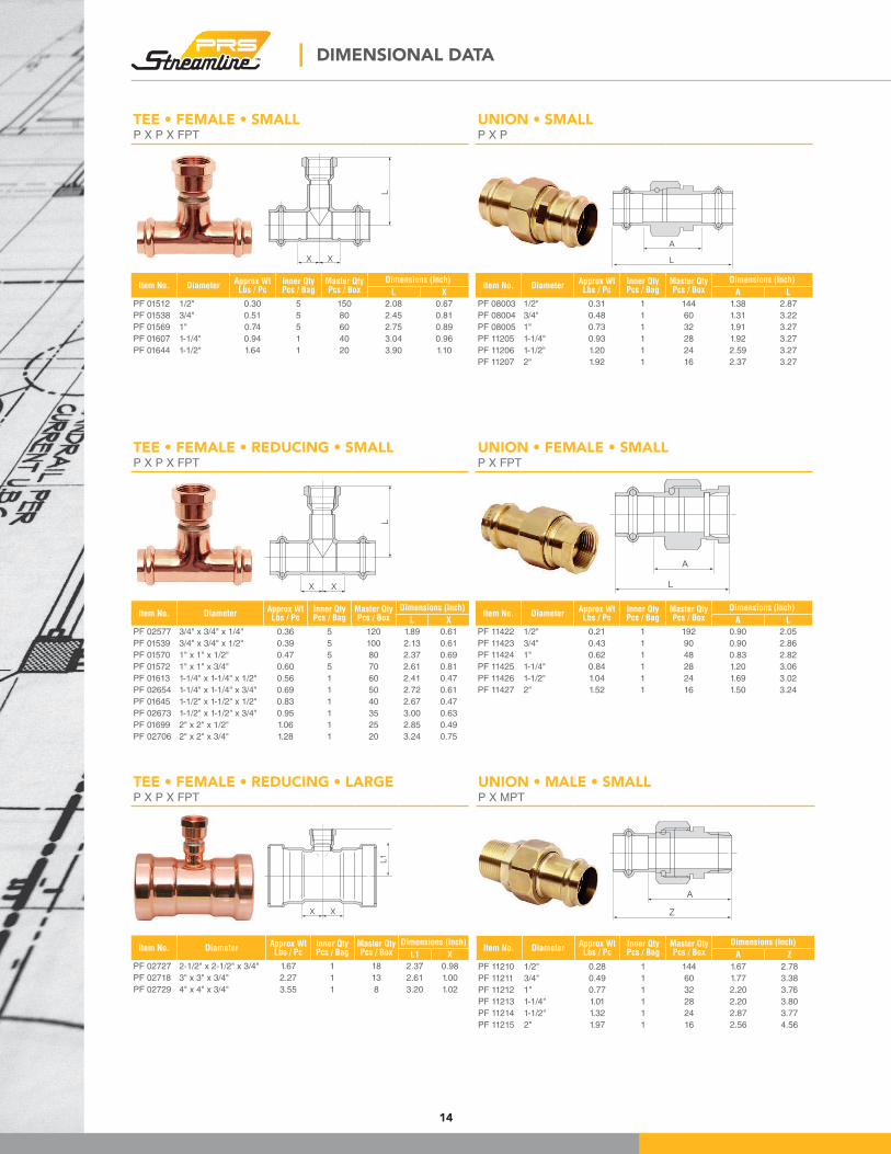
UNION • SMALLP X P
A
L
Item No. DiameterApprox WtLbs / Pc
Inner QtyPcs / Bag
Master QtyPcs / Box
Dimensions (Inch)
A L
PF 08003 1/2" 0.31 1 144 1.38 2.87
PF 08004 3/4" 0.48 1 60 1.31 3.22
PF 08005 1" 0.73 1 32 1.91 3.27
PF 11205 1-1/4" 0.93 1 28 1.92 3.27
PF 11206 1-1/2" 1.20 1 24 2.59 3.27
PF 11207 2" 1.92 1 16 2.37 3.27
UNION • FEMALE • SMALLP X FPT
L
A
Item No. DiameterApprox WtLbs / Pc
Inner QtyPcs / Bag
Master QtyPcs / Box
Dimensions (Inch)
A L
PF 11422 1/2" 0.21 1 192 0.90 2.05
PF 11423 3/4" 0.43 1 90 0.90 2.86
PF 11424 1" 0.62 1 48 0.83 2.82
PF 11425 1-1/4" 0.84 1 28 1.20 3.06
PF 11426 1-1/2" 1.04 1 24 1.69 3.02
PF 11427 2" 1.52 1 16 1.50 3.24
UNION • MALE • SMALLP X MPT
Z
A
Item No. DiameterApprox WtLbs / Pc
Inner QtyPcs / Bag
Master QtyPcs / Box
Dimensions (Inch)
A Z
PF 11210 1/2" 0.28 1 144 1.67 2.78
PF 11211 3/4" 0.49 1 60 1.77 3.38
PF 11212 1" 0.77 1 32 2.20 3.76
PF 11213 1-1/4" 1.01 1 28 2.20 3.80
PF 11214 1-1/2" 1.32 1 24 2.87 3.77
PF 11215 2" 1.97 1 16 2.56 4.56
| DIMENSIONAL DATA
TEE • FEMALE • REDUCING • LARGEP X P X FPT
L1
X X
Item No. DiameterApprox WtLbs / Pc
Inner QtyPcs / Bag
Master QtyPcs / Box
Dimensions (Inch)
L1 X
PF 02727 2-1/2" x 2-1/2" x 3/4" 1.67 1 18 2.37 0.98
PF 02718 3" x 3" x 3/4" 2.27 1 13 2.61 1.00
PF 02729 4" x 4" x 3/4" 3.55 1 8 3.20 1.02
TEE • FEMALE • REDUCING • SMALLP X P X FPT
L
X X
Item No. DiameterApprox WtLbs / Pc
Inner QtyPcs / Bag
Master QtyPcs / Box
Dimensions (Inch)
L X
PF 02577 3/4" x 3/4" x 1/4" 0.36 5 120 1.89 0.61
PF 01539 3/4" x 3/4" x 1/2" 0.39 5 100 2.13 0.61
PF 01570 1" x 1" x 1/2" 0.47 5 80 2.37 0.69
PF 01572 1" x 1" x 3/4" 0.60 5 70 2.61 0.81
PF 01613 1-1/4" x 1-1/4" x 1/2" 0.56 1 60 2.41 0.47
PF 02654 1-1/4" x 1-1/4" x 3/4" 0.69 1 50 2.72 0.61
PF 01645 1-1/2" x 1-1/2" x 1/2" 0.83 1 40 2.67 0.47
PF 02673 1-1/2" x 1-1/2" x 3/4" 0.95 1 35 3.00 0.63
PF 01699 2" x 2" x 1/2" 1.06 1 25 2.85 0.49
PF 02706 2" x 2" x 3/4" 1.28 1 20 3.24 0.75
TEE • FEMALE • SMALLP X P X FPT
X X
L
Item No. DiameterApprox WtLbs / Pc
Inner QtyPcs / Bag
Master QtyPcs / Box
Dimensions (Inch)
L X
PF 01512 1/2" 0.30 5 150 2.08 0.67
PF 01538 3/4" 0.51 5 80 2.45 0.81
PF 01569 1" 0.74 5 60 2.75 0.89
PF 01607 1-1/4" 0.94 1 40 3.04 0.96
PF 01644 1-1/2" 1.64 1 20 3.90 1.10
15
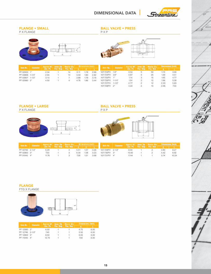
FLANGE • SMALLP X FLANGE
H
L
A
Item No. DiameterApprox WtLbs / Pc
Inner QtyPcs / Bag
Master QtyPcs / Box
Dimensions (Inch)
A H L
PF 02933 1" 2.34 1 14 3.11 1.78 2.68
PF 03806 1-1/4" 2.94 1 14 3.50 1.80 2.82
PF 03907 1-1/2" 3.13 1 7 3.88 1.78 3.19
PF 02980 2" 4.50 1 4 4.76 1.86 3.44
BALL VALVE • PRESSP X P
Item No. DiameterApprox WtLbs / Pc
Inner QtyPcs / Bag
Master QtyPcs / Box
Dimensions (Inch)
A L
107-723PV 1/2" 0.54 5 50 1.15 3.90
107-724PV 3/4" 0.87 5 25 1.39 4.51
107-725PV 1" 1.14 3 15 1.65 4.77
107-726PV 1-1/4" 1.54 2 12 1.96 5.08
107-727PV 1-1/2" 2.77 2 12 2.33 5.83
107-728PV 2" 4.22 2 10 2.96 7.33
FLANGEFTG X FLANGE
Item No. DiameterApprox WtLbs / Pc
Inner QtyPcs / Bag
Master QtyPcs / Box
Dimensions (Inch)
A L
PF 12980 2" 6.50 1 1 4.75 6.00
PF 12746 2-1/2" 7.40 1 1 5.50 6.00
PF 12802 3" 8.50 1 1 6.00 6.00
PF 11940 4" 12.70 1 1 7.50 6.00
FLANGE • LARGEP X FLANGE
H
L
A
Item No. DiameterApprox WtLbs / Pc
Inner QtyPcs / Bag
Master QtyPcs / Box
Dimensions (Inch)
A H L
PF 02746 2-1/2" 6.29 1 4 5.51 1.57 3.26
PF 02802 3" 7.53 1 3 6.30 1.38 3.23
PF 01940 4" 11.76 1 3 7.28 1.51 3.68
DIMENSIONAL DATA |
BALL VALVE • PRESSP X P
Item No. DiameterApprox WtLbs / Pc
Inner QtyPcs / Bag
Master QtyPcs / Box
Dimensions (Inch)
A L
107-729PV 2-1/2" 8.04 1 2 3.90 8.27
107-730PV 3" 10.60 1 2 4.42 8.92
107-731PV 4" 17.44 1 1 5.74 10.24
A
L
A
L
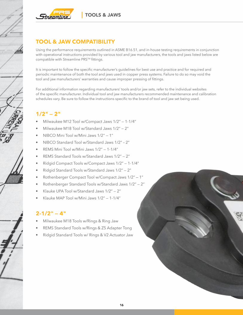
| TOOLS & JAWS
Using the performance requirements outlined in ASME B16.51, and in-house testing requirements in conjunction with operational instructions provided by various tool and jaw manufacturers, the tools and jaws listed below are
compatible with Streamline PRSTM ittings.
It is important to follow the speciic manufacturer’s guidelines for best use and practice and for required and periodic maintenance of both the tool and jaws used in copper press systems. Failure to do so may void the
tool and jaw manufacturers’ warranties and cause improper pressing of ittings.
For additional information regarding manufacturers’ tools and/or jaw sets, refer to the individual websites
of the speciic manufacturer. Individual tool and jaw manufacturers recommended maintenance and calibration schedules vary. Be sure to follow the instructions speciic to the brand of tool and jaw set being used.
1/2" — 2"
• Milwaukee M12 Tool w/Compact Jaws 1/2” — 1-1/4”• Milwaukee M18 Tool w/Standard Jaws 1/2” — 2”• NIBCO Mini Tool w/Mini Jaws 1/2" — 1”• NIBCO Standard Tool w/Standard Jaws 1/2” – 2”• REMS Mini Tool w/Mini Jaws 1/2” — 1-1/4”• REMS Standard Tools w/Standard Jaws 1/2” — 2”• Ridgid Compact Tools w/Compact Jaws 1/2” — 1-1/4”• Ridgid Standard Tools w/Standard Jaws 1/2” — 2”• Rothenberger Compact Tool w/Compact Jaws 1/2“ — 1”• Rothenberger Standard Tools w/Standard Jaws 1/2” — 2”• Klauke UPA Tool w/Standard Jaws 1/2” — 2”• Klauke MAP Tool w/Mini Jaws 1/2” — 1-1/4”
2-1/2" — 4"
• Milwaukee M18 Tools w/Rings & Ring Jaw• REMS Standard Tools w/Rings & Z5 Adapter Tong• Ridgid Standard Tools w/ Rings & V2 Actuator Jaw
TOOL & JAW COMPATIBILITY
16
ENGINEERING DATA |
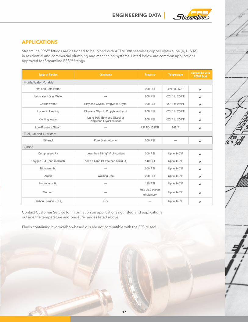
APPLICATIONS
Streamline PRSTM ittings are designed to be joined with ASTM B88 seamless copper water tube (K, L, & M) in residential and commercial plumbing and mechanical systems. Listed below are common applications
approved for Streamline PRSTM ittings.
Contact Customer Service for information on applications not listed and applications
outside the temperature and pressure ranges listed above.
Fluids containing hydrocarbon-based oils are not compatible with the EPDM seal.
Types of Service Comments Pressure TemperatureCompatible with
EPDM Seal
Fluids/Water Potable
Hot and Cold Water — 200 PSI 32°F to 250°F aRainwater / Grey Water — 200 PSI -20°F to 250°F a
Chilled Water Ethylene Glycol / Propylene Glycol 200 PSI -20°F to 250°F aHydronic Heating Ethylene Glycol / Propylene Glycol 200 PSI -20°F to 250°F a
Cooling WaterUp to 50% Ethylene Glycol or
Propylene Glycol solution200 PSI -20°F to 250°F a
Low-Pressure Steam — UP TO 15 PSI 248°F aFuel, Oil and Lubricant
Ethanol Pure Grain Alcohol 200 PSI — aGases
Compressed Air Less than 25mg/m3 oil content 200 PSI Up to 140°F aOxygen - O
2 (non medical) Keep oil and fat free/non-liquid O
2140 PSI Up to 140°F a
Nitrogen - N2
— 200 PSI Up to 140°F aArgon Welding Use 200 PSI Up to 140°F a
Hydrogen - H2
— 125 PSI Up to 140°F a
Vacuum —Max 29.2 inches
of MercuryUp to 140°F a
Carbon Dioxide - CO2
Dry — Up to 140°F a
17
18
| INSTALLATION INSTRUCTIONS
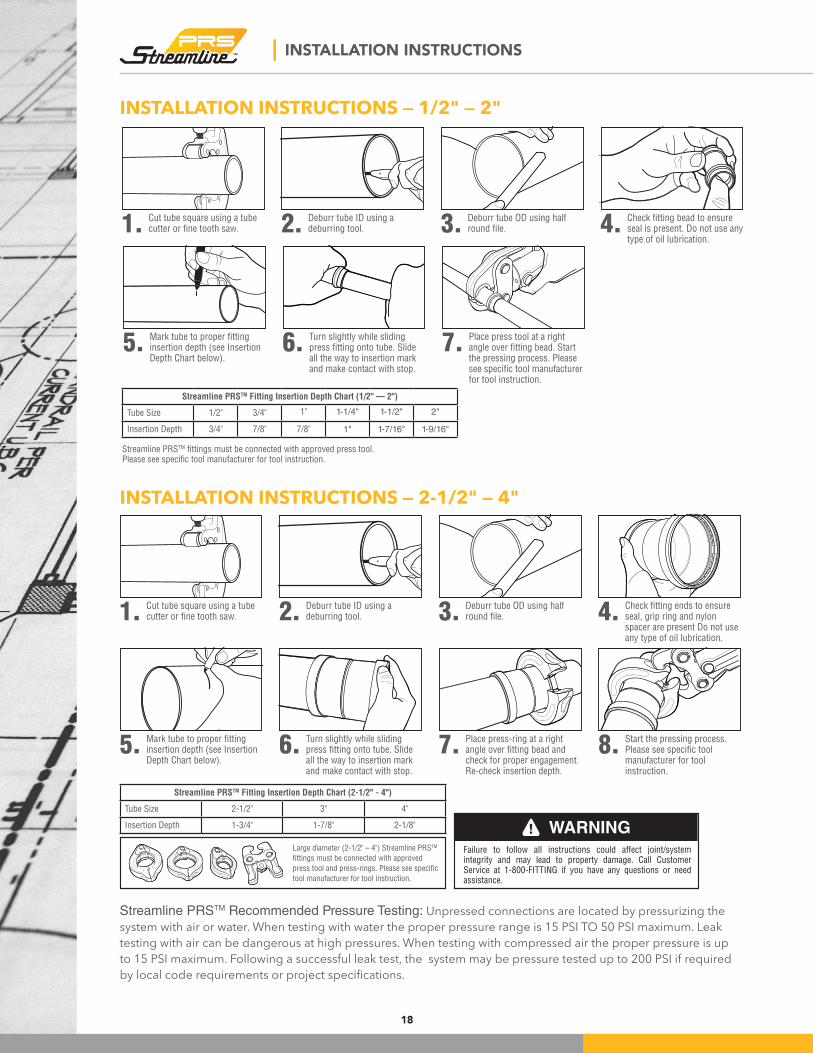
INSTALLATION INSTRUCTIONS — 1/2" — 2"
1.Cut tube square using a tube cutter or fine tooth saw. 3.
Deburr tube OD using half round file.2.
Deburr tube ID using a deburring tool. 4.
Check fitting bead to ensure seal is present. Do not use any type of oil lubrication.
7.Place press tool at a right angle over fitting bead. Start the pressing process. Please see specific tool manufacturer for tool instruction.
5.Mark tube to proper fitting insertion depth (see Insertion Depth Chart below).
6.Turn slightly while sliding press fitting onto tube. Slide all the way to insertion mark and make contact with stop.
Streamline PRSTM Fitting Insertion Depth Chart (1/2" — 2")
Tube Size 1/2" 3/4" 1" 1-1/4" 1-1/2" 2"
Insertion Depth 3/4" 7/8" 7/8" 1" 1-7/16" 1-9/16"
Streamline PRSTM fittings must be connected with approved press tool. Please see specific tool manufacturer for tool instruction.
INSTALLATION INSTRUCTIONS — 2-1/2" — 4"
! WARNINGFailure to follow all instructions could affect joint/system integrity and may lead to property damage. Call Customer Service at 1-800-FITTING if you have any questions or need assistance.
1.Cut tube square using a tube cutter or fine tooth saw. 4.
Check fitting ends to ensure seal, grip ring and nylon spacer are present Do not use any type of oil lubrication.
7.Place press-ring at a right angle over fitting bead and check for proper engagement. Re-check insertion depth.
3.Deburr tube OD using half round file.
6.Turn slightly while sliding press fitting onto tube. Slide all the way to insertion mark and make contact with stop.
2.Deburr tube ID using a deburring tool.
5.Mark tube to proper fitting insertion depth (see Insertion Depth Chart below).
8.Start the pressing process. Please see specific tool manufacturer for tool instruction.
Large diameter (2-1/2" – 4") Streamline PRSTM
fittings must be connected with approved
press tool and press-rings. Please see specific
tool manufacturer for tool instruction.
Streamline PRSTM Fitting Insertion Depth Chart (2-1/2" - 4")
Tube Size 2-1/2" 3" 4"
Insertion Depth 1-3/4" 1-7/8" 2-1/8"
Streamline PRSTM Recommended Pressure Testing: Unpressed connections are located by pressurizing the
system with air or water. When testing with water the proper pressure range is 15 PSI TO 50 PSI maximum. Leak
testing with air can be dangerous at high pressures. When testing with compressed air the proper pressure is up
to 15 PSI maximum. Following a successful leak test, the system may be pressure tested up to 200 PSI if required
by local code requirements or project speciications.
19
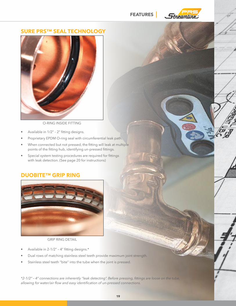
FEATURES |
GRIP RING DETAIL
O-RING INSIDE FITTING
• Available in 1/2” – 2” itting designs.• Proprietary EPDM O-ring seal with circumferential leak path.• When connected but not pressed, the itting will leak at multiple
points of the itting hub, identifying un-pressed ittings.• Special system testing procedures are required for ittings
with leak detection. (See page 20 for instructions)
• Available in 2-1/2” – 4” itting designs.*• Dual rows of matching stainless steel teeth provide maximum joint strength.
• Stainless steel teeth “bite” into the tube when the joint is pressed.
SURE PRS™ SEAL TECHNOLOGY
DUOBITE™ GRIP RING
*2-1/2” – 4” connections are inherently “leak detecting”. Before pressing, ittings are loose on the tube, allowing for water/air low and easy identiication of un-pressed connections.

| TESTING WITH LEAK DETECTION
20
Pressure Testing
When installing Streamline PRSTM ittings it is recommended to perform a leak test in order to locate
any un-pressed ittings. To assist in making that testing more reliable, Streamline PRSTM ittings come with a leak detection feature. The following
procedures allow installers to detect un-pressed ittings in a system under pressure prior to concealment.
Leak Testing with Air
1. When the system, or portion of the system, is
installed and isolated, pressurize to 15 PSI
maximum using dry clean air, carbon dioxide
or nitrogen charge
2. The system should stabilize over the next
several hours (2 – 3 recommended) and the pressure should be monitored with a
pressure gauge.
3. If the pressure has dropped, add more pressure
to bring the system back up to the 15 PSI desired
initial test level. Bleed off excess pressure.
4. Allow another 2-3 hours for complete system stabilization. If upon inspection the system
pressure has dropped below 15 PSI test level,
there is likely an un-pressed itting leaking.
5. Leaks are easily identiied either by use of commercial leak test solution or soap and water
mixture, which will form bubbles identifying an
un-pressed leak point.
6. Once any un-pressed connection has been tested and repaired, repeat the testing process until
15 PSI pressure is maintained for 24 hours or
for the duration of time and pressure speciied by local authority codes.
Leak Testing with Water
1. When the system, or portion of the system, is
installed and isolated, pressurize to 50 PSI
maximum using clean potable water.
2. The system should stabilize over the next
several hours (2 – 3 recommended) and the pressure should be monitored with a
pressure gauge.
3. If the pressure has dropped, add more pressure
to bring the system back up to the 50 PSI desired
initial test level. Bleed off excess pressure.
4. Allow another 2-3 hours for complete system stabilization. If upon inspection the system
pressure has dropped below 50 PSI test level,
there is likely an un-pressed itting leaking.
5. Leaks are easily identiied by leaking water.
6. Once any un-pressed connection has been tested and repaired, repeat the testing process until
50 PSI pressure is maintained for 24 hours or
for the duration of time and pressure speciied by local authority codes.
Once either testing procedure has been
completed and veriied, water/air pressure can be increased to the working pressure
design of the system, not to exceed the
maximum rated pressure.
TESTING INSTRUCTIONS FOR FITTINGS WITH LEAK DETECTION
21
INSTALLATION GUIDELINES |
TUBE SELECTION
Streamline PRSTM ittings are designed to be joined with ASTM B88 (Types K, L, M) hard-drawn copper tube
(1/2" - 4") and soft copper tube (1/2" - 1-1/4").
Copper tubing made to ASTM B88 may contain surface
imperfections, which are speciically deined and allowed by the standard. This product is handled and
stored multiple times before reaching the actual point
of installation, potentially leading to further scratches,
nicks or dents. ASTM B88 copper tube was designed
for joining with solder and braze alloys – both of which are excellent gap-ill materials.
Those who specify and/or install press systems must
be aware of the inherent trade-offs that accompany the decision to utilize press technology and o-ring seals. Installers should recognize surface scratches and deep
incise marks (identiication stamping) on the tube and avoid placing o-ring seals directly over these surface irregularities in order to reduce the risk of leaks.
Sanding and cleaning the surface may or may not
eliminate this concern.
STORAGE AND HANDLING
Streamline PRSTM ittings are packaged in polybags to keep them clean and free from debris. While unlikely to
be needed, the polybag also serves to keep ittings and o-ring seals together in the event that one were to be dislodged in transit. Prior to installation, it is highly
recommended that a thorough visual inspection of
the ittings be performed. Fittings should be handled with care and opened just prior to use, to ensure their
cleanliness.
The tubing and ittings should be carefully handled during shipment and unloaded with reasonable care.
Protect the stored product from moisture and dirt.
Elevation above grade and away from concrete is
desirable.
In the event press ittings are dropped, exercise the utmost care in visually inspecting them to assure that
ittings have not been damaged or deformed.
TOOLS & JAWS
Installer shall be qualiied and licensed within the jurisdiction, and familiar with the installation of copper
press joint systems.
Streamline PRSTM copper press ittings shall be installed using the proper tool, jaws, actuator, and rings
as instructed by the respective press itting and press tool manufacturer.
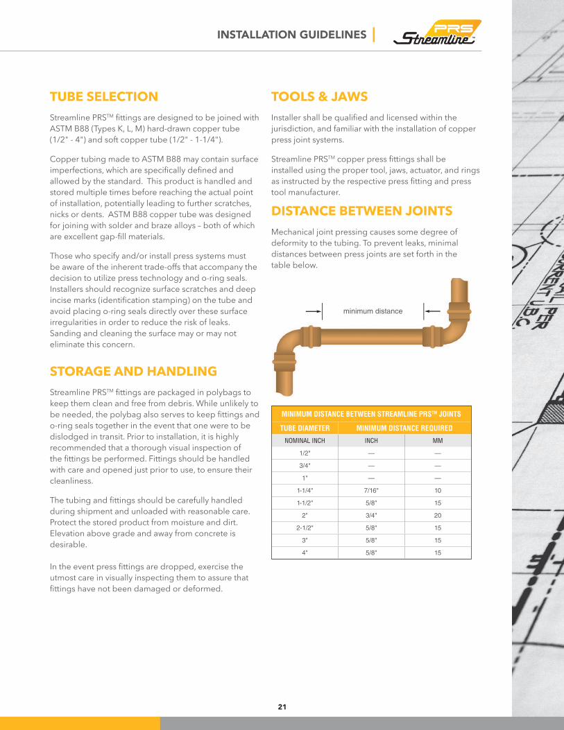
DISTANCE BETWEEN JOINTS
Mechanical joint pressing causes some degree of
deformity to the tubing. To prevent leaks, minimal
distances between press joints are set forth in the
table below.
MINIMUM DISTANCE BETWEEN STREAMLINE PRSTM JOINTS
TUBE DIAMETER MINIMUM DISTANCE REQUIRED
NOMINAL INCH INCH MM
1/2" — —
3/4" — —
1" — —
1-1/4" 7/16" 10
1-1/2" 5/8" 15
2" 3/4" 20
2-1/2" 5/8" 15
3" 5/8" 15
4" 5/8" 15
minimum distance
22
| INSTALLATION GUIDELINES
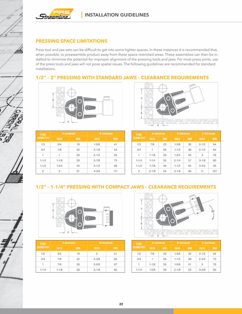
PRESSING SPACE LIMITATIONS
Press tool and jaw sets can be dificult to get into some tighter spaces. In these instances it is recommended that, when possible, to preassemble product away from these space restricted areas. These assemblies can then be in-stalled to minimize the potential for improper alignment of the pressing tools and jaws. For most press joints, use
of the press tools and jaws will not pose spatial issues. The following guidelines are recommended for standard
installations.
TUBE DIAMETER
A minimum B minimum C minimum
INCH MM INCH MM INCH MM
1/2 7/8 23 1-3/8 35 2-1/2 64
3/4 1 26 1-1/2 38 2-1/2 64
1 1-1/8 29 1-3/4 45 3 76
1-1/4 1-1/4 32 2-1/4 57 3-1/8 80
1-1/2 1-7/8 48 1-1/2 64 3-3/4 95
2 2-1/8 54 3-1/8 80 5 127
TUBE DIAMETER
A minimum B minimum C minimum
INCH MM INCH MM INCH MM
1/2 7/8 23 1-3/8 35 2-1/2 64
3/4 1 26 1-1/2 38 2-3/4 70
1 1-1/8 29 1-5/8 41 3 76
1-1/4 1-5/8 39 2-1/8 53 3-3/8 85
TUBE DIAMETER
A minimum B minimum
INCH MM INCH MM
1/2 3/4 19 1-5/8 41
3/4 7/8 22 2-1/8 54
1 1 26 2-1/2 64
1-1/4 1-1/8 29 2-7/8 73
1-1/2 1-3/4 45 3-1/2 89
2 2 51 4-3/8 111
TUBE DIAMETER
A minimum B minimum
INCH MM INCH MM
1/2 3/4 19 2 51
3/4 7/8 22 2-3/8 60
1 7/8 26 2-5/8 67
1-1/4 1-1/8 28 3-1/8 85
1/2” – 2” PRESSING WITH STANDARD JAWS – CLEARANCE REQUIREMENTS
1/2” – 1-1/4” PRESSING WITH COMPACT JAWS – CLEARANCE REQUIREMENTS
23
INSTALLATION GUIDELINES |
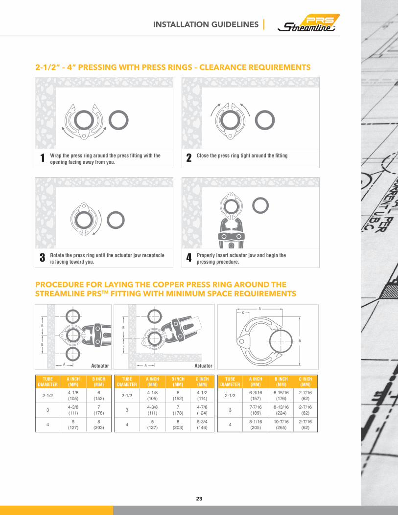
2-1/2” – 4” PRESSING WITH PRESS RINGS – CLEARANCE REQUIREMENTS
PROCEDURE FOR LAYING THE COPPER PRESS RING AROUND THE
STREAMLINE PRSTM FITTING WITH MINIMUM SPACE REQUIREMENTS
TUBE DIAMETER
A INCH (MM)
B INCH (MM)
2-1/24-1/8
(105)
6
(152)
34-3/8
(111)
7
(178)
45
(127)
8
(203)
TUBE DIAMETER
A INCH (MM)
B INCH (MM)
C INCH(MM)
2-1/24-1/8
(105)
6
(152)
4-1/2
(114)
34-3/8
(111)
7
(178)
4-7/8
(124)
45
(127)
8
(203)
5-3/4
(146)
TUBE DIAMETER
A INCH (MM)
B INCH (MM)
C INCH(MM)
2-1/26-3/16
(157)
6-15/16
(176)
2-7/16
(62)
37-7/16
(189)
8-13/16
(224)
2-7/16
(62)
48-1/16
(205)
10-7/16
(265)
2-7/16
(62)
Actuator
Rotate the press ring until the actuator jaw receptacle
is facing toward you.
Properly insert actuator jaw and begin the
pressing procedure.
Wrap the press ring around the press fitting with the
opening facing away from you.
Close the press ring tight around the fitting
Actuator
1
3
2
4
| INSTALLATION GUIDELINES
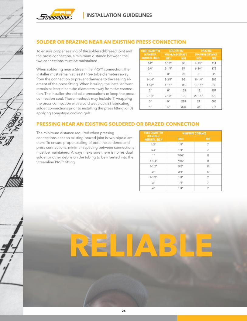
SOLDER OR BRAZING NEAR AN EXISTING PRESS CONNECTION
TUBE DIAMETERDIAMETER
NOMINAL INCH
SOLDERING BRAZING
MINIMUM DISTANCE MINIMUM DISTANCE
INCH MM INCH MM
1/2" 1-1/2" 38 4-1/2" 114
3/4" 2-1/4" 57 6-3/4" 172
1" 3" 76 9 229
1-1/4" 3-3/4" 95 11-1/4" 286
1-1/2" 4-1/2" 114 13-1/2" 343
2" 6" 153 18 457
2-1/2" 7-1/2" 191 22-1/2" 572
3" 9" 229 27 686
4" 12" 305 36 915
TUBE DIAMETERDIAMETER
NOMINAL INCH
MINIMUM DISTANCE
INCH MM
1/2" 1/4" 7
3/4" 1/4" 7
1" 7/16" 11
1-1/4" 7/16" 11
1-1/2" 5/8" 16
2" 3/4" 19
2-1/2" 1/4" 7
3" 1/4" 7
4" 1/4" 7
The minimum distance required when pressing
connections near an existing brazed joint is two pipe diam-eters. To ensure proper sealing of both the soldered and
press connections, minimum spacing between connections
must be maintained. Always make sure there is no residual
solder or other debris on the tubing to be inserted into the
Streamline PRSTM itting.
To ensure proper sealing of the soldered/brazed joint and
the press connection, a minimum distance between the
two connections must be maintained.
When soldering near a Streamline PRSTM connection, the
installer must remain at least three tube diameters away
from the connection to prevent damage to the sealing el-ement of the press itting. When brazing, the installer must remain at least nine tube diameters away from the connec-tion. The installer should take precautions to keep the press
connection cool. These methods may include 1) wrapping
the press connection with a cold wet cloth, 2) fabricating
solder connections prior to installing the press itting, or 3) applying spray-type cooling gels.
PRESSING NEAR AN EXISTING SOLDERED OR BRAZED CONNECTION
RELIABLE
24
FAQs |
25
FREQUENTLY ASKED QUESTIONS:
Streamline PRSTM Fittings for Use in Copper Tube Systems
1. What is the Streamline PRSTM system rated for regarding pressure and temperature?
200 PSI over a temperature range of -20° F to 250° F.
2. For what types of applications is the Streamline PRSTM system approved?
Residential and commercial plumbing and mechanical systems.
3. For what types of media is the Streamline PRSTM system designed?
Hot and cold domestic water, potable drinking and cooking water, condenser and chilled water, and water glycol mixtures of ethylene or propylene glycol up to 50% at 200° F.
4. What products are included in the Streamline PRSTM system offering?
Copper ittings in sizes 1/2” to 4” including couplings, elbows, tees, caps, adapters, itting reducers, unions and langes.
5. What tubing can be used with Streamline PRSTM ittings?
K, L, and M hard drawn copper water tube (1/2” to 4”) and soft (annealed) copper tube (1/2” to 1-1/4”.)
6. What is the warranty for Streamline PRSTM ittings?
50-year limited warranty.
7. How long will the EPDM seal last in Streamline PRSTM ittings?
The EPDM seal carries the same warranty as the itting in which it is installed — 50 years.
8. What performance tests were performed on the Streamline PRSTM ittings?
Certiication to IAPMO PS-117 and ASME B16.51 requires the following tests: hydrostatic burst strength, unrestrained hydrostatic pressure, dynamic torque, static torque, bending, vacuum pressure, cyclic pressure, vibration and thermocycling.
9. What pressing tools can be used with the Streamline PRSTM system ittings?
Most pressing tools on the market can be used, but always refer to the Tool & Jaw Compatibility Chart.
10. Can a Streamline PRSTM itting connection be re-crimped?
Yes. However, for 1/2” to 2” joints, the pressing jaws must be positioned on the same hex lats as the original crimp.
11. Is the Streamline PRSTM system approved for use underground?
Yes, in accordance with local plumbing codes.
26
| FAQS
12. Are Streamline PRSTM ittings lead free?
Yes. They have been tested and are certiied to NSF/ANSI-61 and NSF/ANSI-372.
13. Are Streamline PRSTM system seals lubricated?
The seals are lubricated as part of the manufacturing process when they are inserted into the press ittings.
14. Can Streamline PRSTM ittings be installed in a system subject to freezing?
Care should always be taken when installing any system in severe freezing conditions. Systems exposed to freezing conditions should be protected per local plumbing codes.
15. Can a Streamline PRSTM itting be installed in tight spaces?
Yes, as long as there is sufficient clearance around each joint to allow for the pressing tool and jaw to crimp without interference.
16. What does EPDM stand for?
Ethylene-Propylene Diene Monomer
17. How far away from a Streamline PRSTM connection can another itting be soldered or brazed?
Brazing or soldering should not occur less three pipe diameters from an installed press itting. The installer should protect the press connection by use of a wet rag or cooling gel.
18. How far away from a soldered or brazed can a Streamline PRSTM be installed?
A Streamline PRSTM itting can be installed two pipe diameters from an existing soldered or brazed connection. The installer should take precaution to ensure there is no residual solder or braze material on the sealing surface and that the tube is not hot.
19. How close together can two Streamline PRSTM connections be pressed?
See Minimum Distance Between Streamline PRSTM Joints for distance between press ittings.
20. What are the most common errors made when installing a Streamline PRSTM system?
Not adequately deburring the end of the tubing, and not inserting the tube far enough into the press itting.
21. Can Streamline PRSTM ittings be installed in a refrigeration system?
No. The EPDM seals are not compatible with refrigerants, and the pressure rating of the system is not sufficient for many refrigerant gases.

27
| NOTES

Distributed by Mueller Streamline Co. • 8285 Tournament Drive, Memphis, TN 38125800-846-9750 • www.muellerindustries.com
MLT-361 - FEBRUARY 2018