Embed Size (px)
Citation preview
Site Visit Report: San Manuel Facility
MINE SITE VISIT:
SAN MANUEL FACILITYMAGMA COPPER COMPANY
U.S. Environmental Protection AgencyOffice of Solid Waste
401 M Street SWWashington, DC 20460
Site Visit Report: San Manuel Facility
3-1
3.0 MINE SITE VISIT: SAN MANUEL FACILITY
MAGMA COPPER COMPANY
3.1 INTRODUCTION
3.1.1 Background
The U.S. Environmental Protection Agency (EPA) has initiated several information gathering activities to
characterize mining wastes and mining waste management practices. As part of these ongoing efforts, EPA is
gathering data related to waste generation and management practices by conducting visits to mine sites. As
one of several site visits, EPA visited Magma Copper Company's San Manuel Facility in San Manuel,
Arizona on May 5 and 6, 1992.
Sites to be visited were selected by EPA to represent both an array of mining industry sectors and different
regional geographies. All site visits have been conducted pursuant to RCRA Sections 3001 and 3007
information collection authorities. When sites have been on Federal land, EPA has invited representatives of
the land management agencies (Forest Service and Bureau of Land Management). State agency
representatives and EPA Regional personnel have also been invited to participate in each site visit.
For each site, EPA has collected information using a three-step approach: (1) contacting the facility by
telephone to obtain initial information, (2) contacting state regulatory agencies by telephone to get further
information, and (3) conducting the actual site visit. Information collected prior to the visit is then reviewed
during the site visit.
The site visit reports describe mine activity, mine waste generation and management practices, and regulatory
status on a site-specific basis. These reports principally discuss extraction and beneficiation operations,
although a brief discussion of processing operations is also included. In preparing this report, EPA collected
information from a variety of sources including Magma Copper Company and the Arizona Department of
Environmental Quality. The following individuals participated in the San Manuel Facility site visit on May 5
and 6, 1992:
Magma Copper Company
Eldon D. Helmer, Director of Environmental Affairs (602) 575-5600Dale Deming, Manager of Environmental Services (602) 385-3540Norm Greenwald, Consultant, Norm Greenwald Associates (602) 795-0471
Site Visit Report: San Manuel Facility
3-2
EPA
Van Housman, Chemical Engineer, Office of Solid Waste (OSW) (703) 308-8419Patty Whiting, Environmental Protection Specialist, Office of Solid Waste (OSW) (703) 308-8421Haile Marion, Chemical Engineer, Office of Solid Waste (OSW) (703) 308-8439Lisa Jones, Chemical Engineer, Office of Solid Waste (OSW) (703) 308-8451
Science Applications International Corporation
Ingrid Rosencrantz, Environmental Scientist (703) 734-2508Susan McCarter, Environmental Analyst (703) 734-3187
Participants in the site visit were provided opportunity to comment on a draft of this report. Comments were
submitted by the Arizona Department of Environmental Quality. Comments and EPA's responses are
presented in Appendix 3-A.
3.1.2 General Description
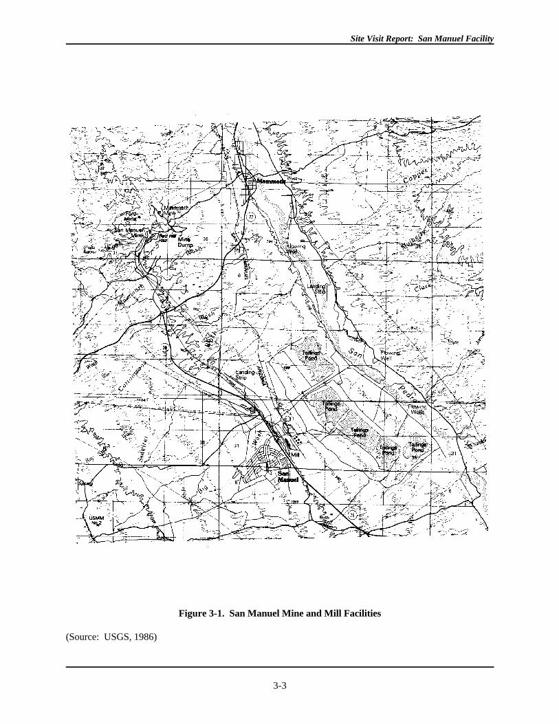
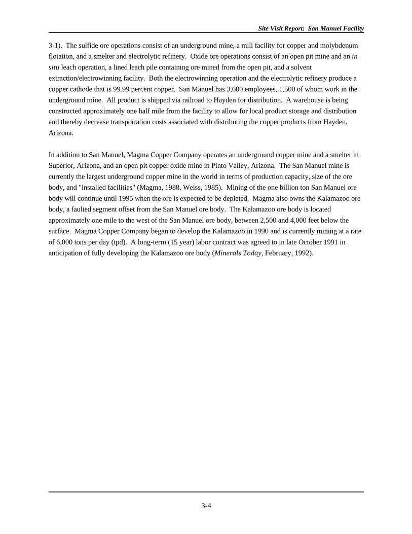
Magma Copper Company operates the San Manuel mine, mill, and smelter facilities located north of Tucson,
Arizona, in Pinal County. The facility encompasses approximately 12,000 acres of patented land with
operations that extract, beneficiate, and process both sulfide and oxide ore to recover copper and
molybdenum (See Figure
Site Visit Report: San Manuel Facility
3-3
Figure 3-1. San Manuel Mine and Mill Facilities
(Source: USGS, 1986)
Site Visit Report: San Manuel Facility
3-4
3-1). The sulfide ore operations consist of an underground mine, a mill facility for copper and molybdenum
flotation, and a smelter and electrolytic refinery. Oxide ore operations consist of an open pit mine and an in
situ leach operation, a lined leach pile containing ore mined from the open pit, and a solvent
extraction/electrowinning facility. Both the electrowinning operation and the electrolytic refinery produce a
copper cathode that is 99.99 percent copper. San Manuel has 3,600 employees, 1,500 of whom work in the
underground mine. All product is shipped via railroad to Hayden for distribution. A warehouse is being
constructed approximately one half mile from the facility to allow for local product storage and distribution
and thereby decrease transportation costs associated with distributing the copper products from Hayden,
Arizona.
In addition to San Manuel, Magma Copper Company operates an underground copper mine and a smelter in
Superior, Arizona, and an open pit copper oxide mine in Pinto Valley, Arizona. The San Manuel mine is
currently the largest underground copper mine in the world in terms of production capacity, size of the ore
body, and "installed facilities" (Magma, 1988, Weiss, 1985). Mining of the one billion ton San Manuel ore
body will continue until 1995 when the ore is expected to be depleted. Magma also owns the Kalamazoo ore
body, a faulted segment offset from the San Manuel ore body. The Kalamazoo ore body is located
approximately one mile to the west of the San Manuel ore body, between 2,500 and 4,000 feet below the
surface. Magma Copper Company began to develop the Kalamazoo in 1990 and is currently mining at a rate
of 6,000 tons per day (tpd). A long-term (15 year) labor contract was agreed to in late October 1991 in
anticipation of fully developing the Kalamazoo ore body (Minerals Today, February, 1992).
Site Visit Report: San Manuel Facility
3-5
In addition to producing copper from sulfide ore from the underground mine, San Manuel operates a flotation
circuit for "re-concentration" and "re-processing" of smelter slag. Molten slag from the furnace contains 1.8
percent copper while slag from the converters contains 7 percent copper, concentrations that far exceed
concentrations found in the ore (0.7 percent found in sulfide ore) (Weiss, 1985; Magma, 1992c). Slag
concentrate from flotation is combined with sulfide ore concentrate and is fed to the smelter.
Investigations of the San Manuel area began in the early 1940s during an increase in demand for copper and
other metals. Exploration drilling began in 1943 in the Red Hill area of San Manuel, and claims were
purchased by Magma Copper Company in 1944. In 1952, the Reconstruction and Finance Corporation
authorized a $94 million loan to Magma for construction of the mine, the plant, railroads, and the company
town. (Weiss, 1985) Production level mining began in 1954, following six years of underground exploration
and development work. In 1969, Magma was sold to Newmont Mining Corporation. In 1987, Magma was
reorganized and spun off to Newmont stockholders. Within two years, Newmont interests in San Manuel
were recapitalized and repurchased by Magma. (Magma, 1988)
3.1.3 Environmental Setting
Magma Copper Company's San Manuel facilities are located in the semi-arid southwest desert, an area
characterized by a dry climate with warm summers and moderate winters. Average temperatures are
approximately 45 degrees Fahrenheit in January and approximately 80 degrees Fahrenheit in July. Based on
records dating back to 1954, precipitation in the area averages 13.4 inches/year, with most precipitation
occurring during the months of February and August. Although evaporation rates were not measured at the
site, evaporation rates in the area are high, with annual evaporation rates of 116 to 118 inches per year
measured near Tucson, Arizona.
The town of San Manuel was built in 1950 and is located near the mill. The community consists of
approximately 1,200 homes with a population of 5,000. Drinking water is pumped from deep wells in the
San Pedro regional aquifer located near the tailings impoundments. As shown in Figure 3-1, the town of
Mammoth is the closest town to the mine site, located 1.6 miles northwest with a population of 2,000. The
site is bordered on the east by the Galiuro mountains and on the west by the Santa Catalina mountains. The
site is west of the Coronado National Forest. The area's primary economic activity is mining, though the San
Pedro valley is also used for ranching. According to Magma representatives, cattle graze in areas near the
tailings impoundments but not in the area near the mine. No endangered, threatened, or State-protected
species are known to be present on facility property or located within one mile of any facility boundary.
3.1.3.1 Geology
The San Manuel ore body is located in the Lower San Pedro River Basin, in an area of bedrock characterized
by intrusive, extrusive, and sedimentary rocks from Precambrian to Pleistocene age, with the oldest rocks
found being the quartz monzonite, granodiorite, and minor diabase and aplite of Precambrian age. (Magma,
1992a) The ore body is an elliptical-shaped granodiorite porphyry cylinder that measures 8,000 feet in
Site Visit Report: San Manuel Facility
3-6
length, 2,500 feet across, and is situated from 700 to 3,000 feet below the surface. A faulted segment of this
ore body lies one mile to the west and is similar in size to the San Manuel ore body. This ore body, called the
"Kalamazoo," lies approximately 2,500 to 4,000 feet below the surface and is currently being developed by
Magma Copper Company (Magma, 1988).
The San Manuel ore body contains "zones of disseminated copper mineralization at an average grade of 0.65
percent copper or approximately 13 pounds of copper per ton of ore" (Magma Copper, 1988). The
Kalamazoo porphyry contains a copper grade of 0.75 percent copper and 0.015 percent molybdenite. Copper
porphyry is characterized by small percentages of copper in a large deposit of country rock containing other
minerals, such as molybdenum, lead, zinc, manganese, gold, and silver. (Guilbert, 1986) The oxide ore
mined at San Manuel is chrysocolla (Cu H (Si O )(OH) ). The sulfide ore is chalcopyrite (CuFeS ). 2 2 2 5 4 2
The San Manuel mine and mill facilities are located in the Lower San Pedro River Basin. (Magma, 1992a)
The Lower San Pedro River Basin extends from a bedrock constriction dividing the Upper and Lower San
Pedro River basins near Benson, Arizona, to the confluence of the San Pedro and Gila Rivers near
Winkelman, Arizona, a distance of approximately 65 miles, ranging from 15 to 30 miles wide. Rock types
found in the area include Precambrian quartz monzonite found in the Santa Catalina Mountain Block;
Cretaceous and Tertiary intrusive, extrusive, and sedimentary rocks found in the Galiuro Mountain Block; the
Pliocene-Pleistocene Gila Conglomerate; and Quaternary and Recent gravels and alluvium found in the
pediment layers and San Pedro River channel.
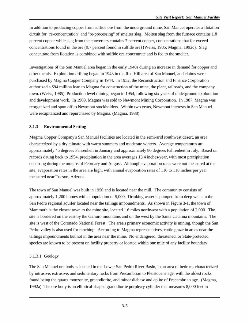
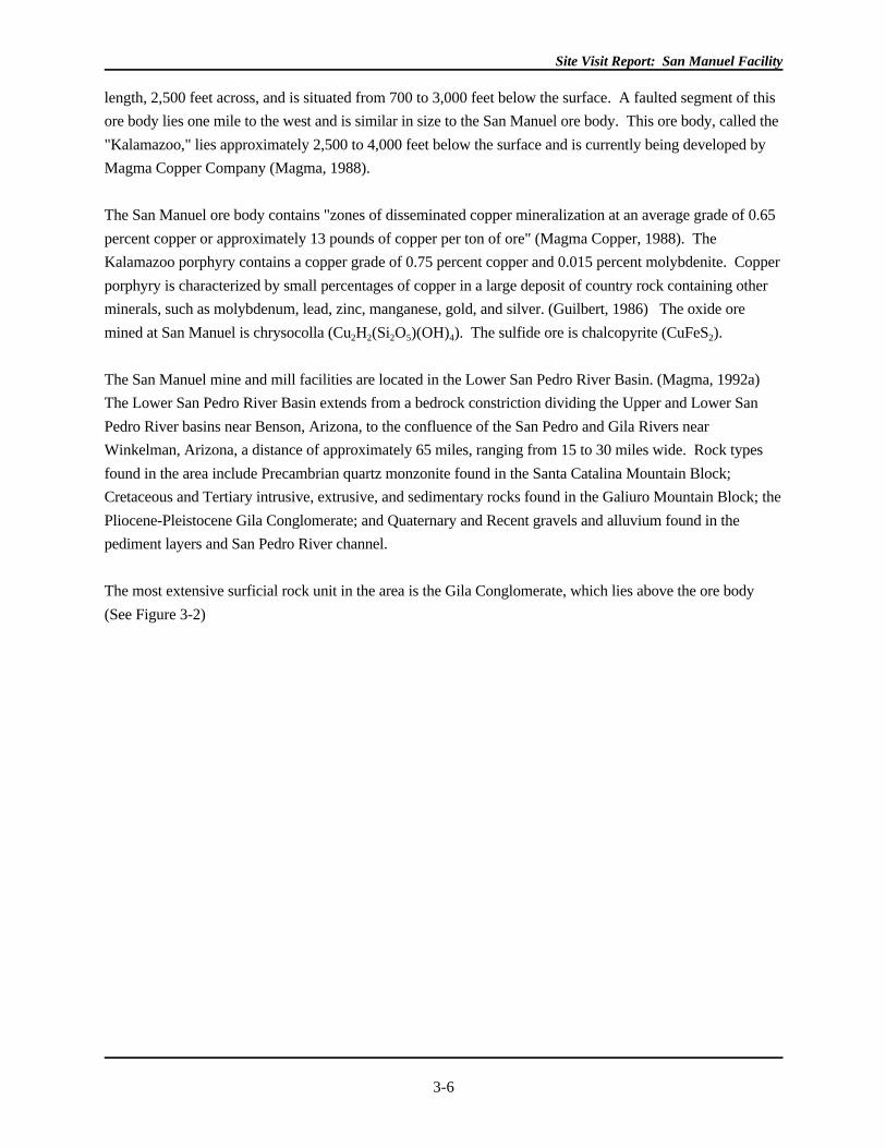
The most extensive surficial rock unit in the area is the Gila Conglomerate, which lies above the ore body
(See Figure 3-2)
Site Visit Report: San Manuel Facility
3-7
Figure 3-2. Structure of San Manuel-Kalamazoo Deposit
(Source: Guilbert, 1986)
Site Visit Report: San Manuel Facility
3-8
. The Gila Conglomerate is characterized by indurated boulder and cobble conglomerate, unconsolidated
marls and limy silts and clays, and an unconsolidated sand and conglomerate. These units of the Gila
Conglomerate are identifiable on a topographic map based on the degree of dissection of each unit (See
Figure 3-1). The marl and limy silt unit is the most heavily dissected showing steep-sided, narrow gullies,
while the unconsolidated sand and conglomerate unit exhibits a smooth land surface. An unconsolidated cap
of gravel overlies the Gila Conglomerate. Adjacent to the San Pedro River channel, Recent alluvium
consisting of unconsolidated gravels, sands and silts, ranging in thickness from 40 to 90 feet, covers the
gravel and Gila Conglomerate layers (Magma, 1992a).
Site Visit Report: San Manuel Facility
3-9
The landscape is characteristic of the Basin and Range physiographic province. The area is defined by four
distinct physiographic features: the modern San Pedro River channel and floodplain, the Whetstone pediment,
the Tombstone pediment and the Santa Catalina Mountain Block. The San Pedro River floodplain extends 5
to 75 feet above the current channel level and roughly 1/2 mile on either side of the channel. The alluvium in
the floodplain is comprised of sedimentary and volcanic rocks common to the region. Alluvial deposits
extending beyond the floodplain are locally referred to as the Whetstone pediment, characterized by
unconsolidated fine-grained silts and clays that extend outward 3 miles (slopes on the Whetstone pediment
range from 150 to 180 feet per mile extending from gradational contact with the floodplain to an elevation of
approximately 3,400 feet). (Magma, 1992a) The Tombstone pediment is characterized by semi-consolidated
to consolidated coarse-grained gravels and cobbles and begins at the gradational contact with the Whetstone
pediment at the 3,400 foot elevation. This pediment extends to the Santa Catalina Mountain Block which
begins at the 4,000 foot elevation with slopes ranging from 200 to 250 feet per mile. The Santa Catalina
Mountain Block comprised of quartz monzonite reaches an elevation of 4,200 feet in the area. Weathering of
this mountain block has contributed to the thin layer of unconsolidated quartz and granitic gravel on the Gila
Conglomerate in the area of the San Manuel mill site. (Magma, 1992a)
Based on the above description of terrace development in the Lower San Pedro River Basin, San Manuel's
tailings impoundments located 1/2 mile west of the San Pedro River are situated on the Whetstone pediment,
while the mill facility, smelter, and town of San Manuel extend beyond the Whetstone pediment to the
Tombstone pediment. According to Magma representatives, the tailings impoundments were constructed on
Gila Conglomerate, an alkaline rock type by nature, that is capable of neutralizing the more acidic nature of
the tailings. No data discussing the alkalinity of the Gila Conglomerate or its neutralization potential was
available. (According to a 1989 study by PEI Associates, Gila Conglomerate in the San Manuel area is
capable of neutralizing 200 pounds of sulfuric acid per ton of Gila Conglomerate.) (U.S. EPA, 1989)
3.1.3.2 Hydrology
Surface Water: Surface water in the vicinity of the site is limited to the San Pedro River and its tributaries.
These are all intermittent streams which maintain highest flows after late summer and winter rainstorms. The
San Pedro River is approximately 1/2 mile from the tailings ponds near the mill facility and was not visibly
flowing at the time of the site visit. Numerous washes (tributaries to the San Pedro River) also drain
naturally through the mill facility and tailings impoundments. In order to prevent storm water runon from
reducing tailings impoundment capacities, Magma diverted Courthouse Wash away from the tailings
impoundments. References do not indicate when the diversion was implemented (Courthouse Wash is not
shown on Figure 3-1). The mine site is 3.5 to 4 miles from the river and is situated between the Tucson Wash
to the north and the Mammoth Wash to the south. (Magma, 1992a)
Groundwater: According to Magma, two aquifers underlie the San Manuel area, the floodplain aquifer and
the regional San Pedro aquifer (Magma 1992a). The floodplain aquifer consists of groundwater in the
floodplain alluvium, which is recharged by precipitation, San Pedro River flow, and seepage from irrigation
systems. The regional aquifer is located within the Gila Conglomerate and is recharged by precipitation
Site Visit Report: San Manuel Facility
3-10
along the mountain fronts and by stream channel infiltration. According to Magma personnel, dewatering
operations at the mine have created an 8-mile cone of depression in the surrounding water table. Impacts on
the local groundwater regime caused by the tailings impoundments and pumping from production wells near
the tailings impoundments are unclear from the available references. According to an undated study provided
by Magma, groundwater in the floodplain is found at depths ranging from 17.4 to 19.3 feet. However,
production well information also provided by Magma indicates that two of 11 production wells located below
the tailings ponds are artesian.
As described earlier, dewatering in the vicinity of the mine site has created a cone of depression in the area's
water table. According to Magma representatives during the site visit in May 1992, the cone of depression
encompassed an area eight miles in diameter from the underground mine. However, the 1991 Aquifer
Protection Permit (APP) for the heap leach facility describes the cone of depression impacting an 11 square
mile area surrounding the mine, substantially less area than the eight mile cone of depression statistic
presented during the site visit. In addition, the APP also describes the cone of depression extending from one
half to two miles around the mine. Thus, the extent of the cone of depression is not clear.
Published material on the cone of depression is described below. Since the current depth of underground
operations is at the 4,080 foot level, the lowest point in the cone of depression may be this same level.
According to Magma, the cone of depression has impacted water levels in all directions except to the south
and southwest where recharge occurs from the Santa Catalina Mountain Block. A borehole monitored
between 1967 and 1982 in the recharge area near the minesite found very little change in ground water levels
that measured 2,952 feet above mean sea level (amsl) (Magma, 1991-APP, undated). The deepest area of the
cone of depression may be directly under the underground mine. Water level measurements in boreholes in
this area have decreased up to 1850 feet due to the dewatering. In addition, as of 1982, the elevation of the
water table 1/2 mile to the southeast of the mine had dropped 800 feet. Between 1935 and 1959, ground
water levels in the Mohawk mine shaft northwest of the San Manuel mine had decreased almost 400 feet,
from 2,504 to 2,106 amsl. (Magma, 1991-APP, undated) The Mohawk mine shaft is currently the most
northwestward monitoring point for water levels.
Groundwater from the San Pedro regional aquifer is used as drinking water by the town of San Manuel and
also supplies make-up water to the facility. Eleven water supply wells were drilled between 1947 and 1974
that pump approximately 14 million gallons per day from the regional aquifer for use by the town and the
mill facility. All eleven wells are situated below the tailings
Site Visit Report: San Manuel Facility
3-11
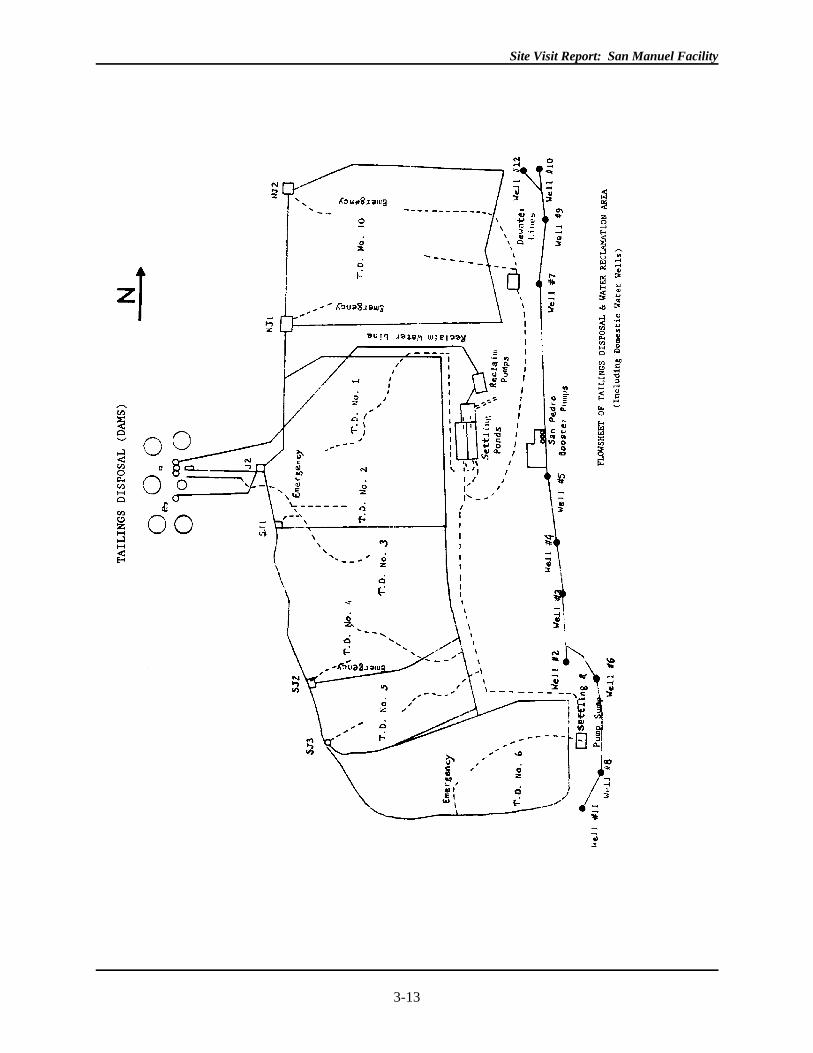
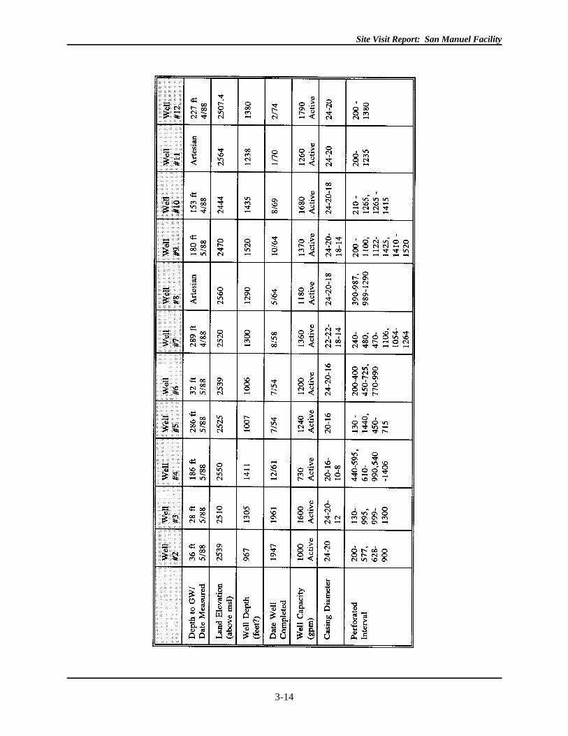
impoundments and just west of the San Pedro River, as depicted in Figure 3-3. Well depths range from 967
feet at Well #2, completed in 1947, to 1,520 feet at Well #9, completed in 1964. According to 1988
information, Well #'s 8 and 11 are artesian. These wells are located immediately below tailings impoundment
No. 6. (See Figure 3-3 and Table 3-1) (Magma, 1992d) According to facility personnel, water from these
wells has been shown to contain elevated fluoride levels. However, no information was obtained explaining
the source of the high fluoride levels.
Site Visit Report: San Manuel Facility
3-12
Site Visit Report: San Manuel Facility
3-13
Figure 3-3. San Manuel Tailings Impoundments and Water Supply Wells
Site Visit Report: San Manuel Facility
3-14
Table 3-1. San Manual Production Wells
Site Visit Report: San Manuel Facility
3-15
Fig
ure
3-3.
San
Man
uel T
ailin
gs I
mpo
undm
ents
and
Wat
er S
uppl
y W
ells
(Sou
rce:
Mag
ma,
199
0)

Site Visit Report: San Manuel Facility
3-16
Site Visit Report: San Manuel Facility
3-17
Tab
le 3
-1.
San
Man
ual P
rodu
ctio
n W
ells
(Sou
rce:
AD
EQ
Pub
lic W
ater
Sup
ply
Syst
em a
nd I
nven
tory
)
Site Visit Report: San Manuel Facility
3-18
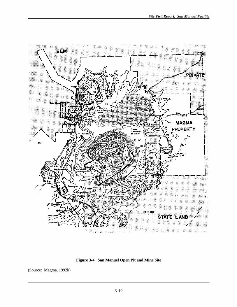
3.2 FACILITY OPERATIONS
The San Manuel facility includes two separate areas of operation: the mine complex, which includes the
underground and open pit mines, the heap leach, and SX/EW facilities; and the mill and smelting complex,
which includes the concentrator, tailings ponds, and smelter facilities. The mine site area is located
approximately six miles north of the mill facility and tailings area on Route 76. The main structures at the
mine complex are the open pit; seven mine shafts and headframes; the heap leach pad that covers
approximately 230 acres; the pregnant, plant feed, and raffinate ponds; the SX/EW plant; a train line for
hauling sulfide ore to the mill; a mine water pond; and many support facilities (e.g., shops, offices, etc.). The
mine site also includes old Tiger Mine workings and waste rock piles generated largely from open pit
operations. (See Figure 3-4)
Site Visit Report: San Manuel Facility
3-19
Figure 3-4. San Manuel Open Pit and Mine Site
(Source: Magma, 1992k)
Site Visit Report: San Manuel Facility
3-20
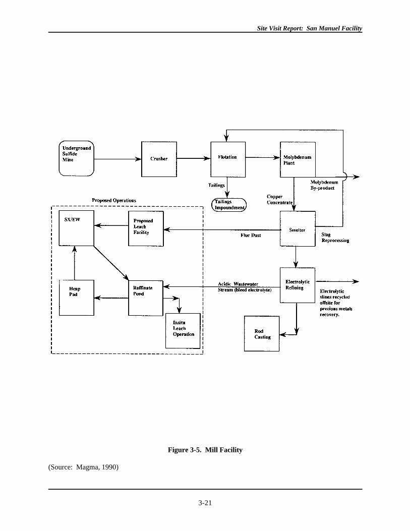
The mill and smelter complex includes the crushing and concentrator buildings, the molybdenum plant, the
smelter, the acid plant, the electrolytic refinery, tailings thickeners, seven tailings ponds covering
approximately 3,600 acres, and associated support facilities. (See Figure 3-5)
Site Visit Report: San Manuel Facility
3-21
Figure 3-5. Mill Facility
(Source: Magma, 1990)
Site Visit Report: San Manuel Facility
3-22
Both sulfide and oxide copper ores are mined at San Manuel. Magma uses underground block-caving mining
methods to extract sulfide ore, and open pit mining to extract oxide ore. The sulfide ore is sent to the mill,
smelter, and refinery, while oxide ore goes to the leach pad and the SX/EW plant. The average grade of
copper ore removed from the San Manuel ore body is approximately 0.65 percent copper, or 13 pounds of
copper in each ton of ore (Magma, 1988). Because Magma recovers two types of ore by distinctly separate
methods, the following description of facility operations is divided into two sections by type of ore.
3.2.1 Oxide Ore
The oxide ore body, containing the oxide mineral chrysocolla, was identified in the Northeast portion of the
subsidence zone of the San Manuel underground mine (Magma, 1988). Mining of this ore body began in
1986 with the availability of new technologies that made recovery of copper from these lower copper oxide
ores economically feasible. The subsidence area created by underground mining currently extends to a depth
of 1,300 feet. Magma's open pit mine currently extends to a depth of 800 feet into the subsidence area. Open
pit mining generates approximately 30,000 tons of ore and up to 68,000 tons of waste rock per day and is
expected to continue until 1995, when the oxide ore body will be exhausted (Magma, 1988).
3.2.1.1 Open Pit Extract
Ore is removed from the pit by drilling blastholes that are 37 feet deep and 9 and 7/8 inch in diameter. Blast
patterns consist of between 30 and 120 blastholes. Blasting locations are generally spaced 24 feet apart, and
the holes may be pump-drilled prior to blasting.

Site Visit Report: San Manuel Facility
3-23

Site Visit Report: San Manuel Facility
3-24
Site Visit Report: San Manuel Facility
3-25
Blasting is accomplished with ANFO, a mixture of ammonium nitrate and diesel fuel (Magma, 1992b).
Periodically, mining hits small perched aquifers and drill holes are pumped prior to blasting. Front end
loaders are used to convey the ore to 100 or 120 ton electric diesel haul trucks. Two Caterpillar graders, as
well as several track dozers, are also used in the mine (Magma, 1992b). Roads in the open pit are 80 feet
wide, graded to a maximum slope of 10 percent to accommodate the haul trucks (Magma, 1988). Pit benches
are built with a cut/strip ratio of 1:1, to ensure the stability of underground mine workings. Benches on the
north side of the pit accommodate in situ leaching wells; these are described below (Magma, 1988). Ore
from the pit is transported to the 230-acre heap leach pad. Waste rock is currently being disposed of in an
angle of repose waste rock pile located inside the pit, on the southern edge.
According to a 1989 topographic map (Figure 3-4), the pit extends approximately 4,200 feet east to west,
and 5,200 feet north to south. The current dimensions of the open pit were not determined. At the time of the
site visit, mining had reached a depth of 800 feet and is anticipated to reach a final depth of 1,200 feet.
Between January 1, 1986 and March 31, 1991, almost 46 million tons of ore and over 95 million tons of
waste rock were removed from the open pit mine, with approximately 50,000 tons of waste rock moved per
day (Magma, 1992b). The stripping ratio for this period is 2.08:1 (waste to ore). After March 1991, an
estimated 73 million tons of material remain to be removed from the pit, which will yield an additional 46
million tons of oxide ore and over 27 million tons of waste rock, a rate of 40,000 tpd (Magma, 1992). For
this period the mine has a stripping ratio of 1:1.7 (waste to ore).
References do not indicate the reason for the decrease in the waste rock mined.
3.2.1.2 Beneficiation of Oxide Ores
Beneficiation of oxide ore at San Manuel includes the in situ leach operation and the heap leach facility,
where oxide ore is leached with acid, as well as the associated solvent extraction and electrowinning plants.
Pregnant leach solution from the in situ leaching operation and the heap leach is sent through a series of
extraction and stripping stages in the solvent extraction plant. Cathode copper (99.999 percent pure) is
recovered in the electrowinning plant.
In situ Leaching
In situ leaching is a solution mining method designed to leach out valuable minerals without removing the
ore. In situ leaching production began in 1987 at San Manuel and is currently located on the north side of the
open pit. In situ wells drilled into mine benches access additional reserves of acid-soluble oxide ore located
beneath the open pit and above the depleted portion of the underground sulfide ore mine (Magma, 1988).
The wells are made of PVC piping and are drilled to a depth of 1,000 feet into an area of the ore reserve that
has been rubbleized by underground mining. Approximately 272 million tons of ore in the underground mine
workings are currently subjected to the in situ leaching process with an estimated two billion gallons of
solution currently in inventory within the in situ ore body (Magma, 1988). Because open pit operations may
extend into in situ leach areas, in situ wells at San Manuel are typically temporary wells that fail when open
Site Visit Report: San Manuel Facility
3-26
pit mining extends into those areas. Magma drills new wells to accommodate additional leaching operations
as necessary. The number of in situ wells in operation at any one time was not determined.
Raffinate solution, a weak sulfuric acid, from the solution extraction (SX) plant is pumped from the raffinate
pond to the in situ wells and injected into the ore body at a rate of 3,000 gpm, or approximately 21,000 tpd
(Magma, 1992b). Solutions percolate through the oxide ore body, and copper-bearing solution is collected in
one of two ways: via recovery wells equipped with submersible pumps; or in the old portion of the
underground sulfide mine at the 1,400 and 1,800 levels (Magma, 1988, 1992). In these old underground
workings, panels have been dammed to create collection areas. Total pregnant leach solution recovered by
these collection methods is 3,100 gpm or 22,320 tpd (Magma, 1992). The recovered solution has a high
solids content (approximately 600 ppm), and is pumped to the surface from the underground sulfide mine to a
sedimentation pond, where the solution is clarified. Flocculants are added to encourage precipitation of the
solids in this pond and pregnant solution is fed to the Plant Feed pond where it is combined with pregnant
leach solution from the heap leach and sent to the SX/EW plant. Solids that accumulate in the sedimentation
pond are dredged and disposed of in the subsidence area beside the open pit. (Magma, 1992b) Information
on the constituent analysis of the sediments, and the location and construction of the sedimentation pond, was
not obtained.
Copper production from the in situ operation was not fully operational until the ore body was completely
saturated and the volume of raffinate solution injected equaled the amount of pregnant solution recovered.
Initially, raffinate from the SX process was sent to the in situ wells at a flow rate of 8,000 gallons per minute
(gpm). The amount of pregnant leach solution recovered in the panels measured a flow rate of only 7,200
gpm, a solution loss of 800 gpm to surrounding ore and country rock. It was not determined when the in situ
operation achieved one hundred percent solution balance.
Heap Leach
Run-of-mine oxide ore from the open pit is hauled to the heap leach at a rate of approximately 30,000 tpd.
The heap leach pad is approximately 3,000 feet wide by 6,000 feet long, covering 230 acres (See Figure 3-6)
Site Visit Report: San Manuel Facility
3-27
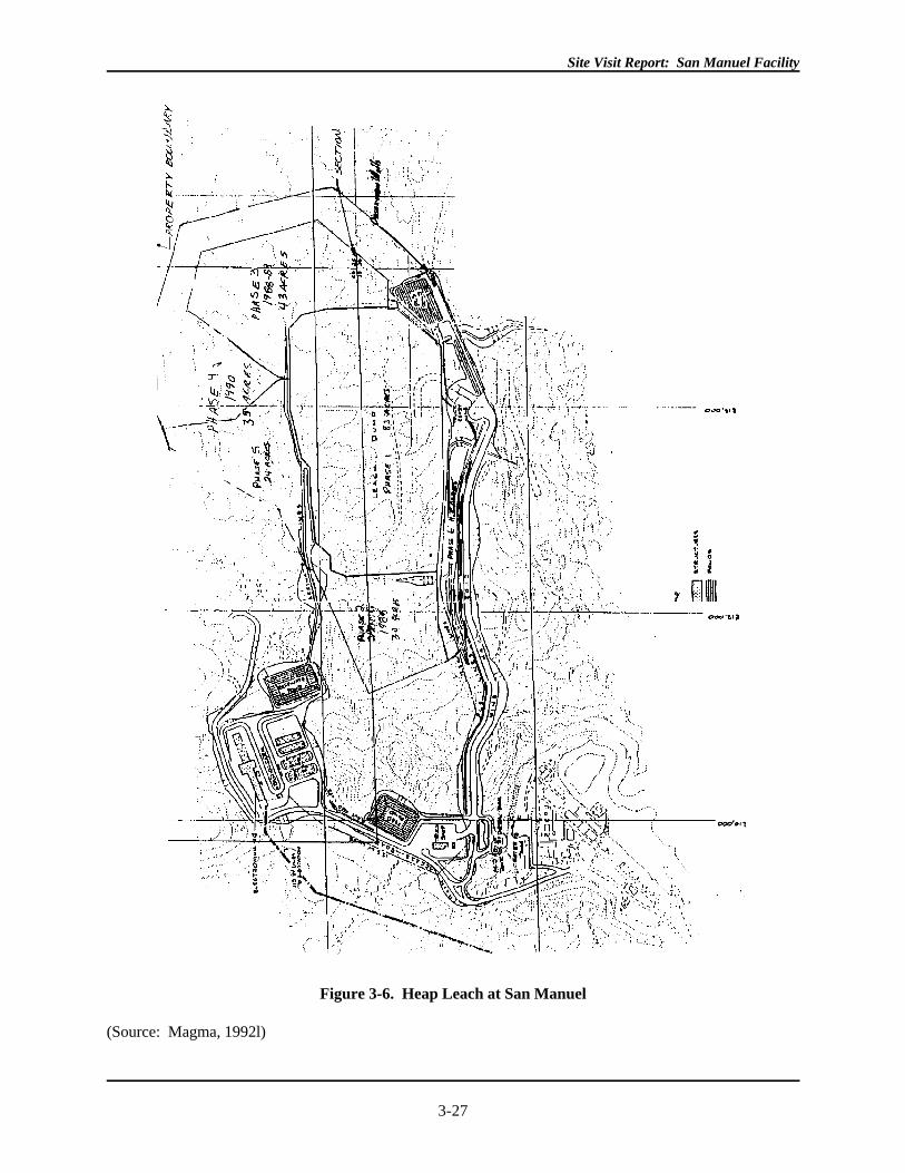
Figure 3-6. Heap Leach at San Manuel
(Source: Magma, 1992l)
Site Visit Report: San Manuel Facility
3-28
(Magma, 1989). According to San Manuel's 1989 Groundwater Quality Protection Permit (GWQPP), the
heap was originally designed to cover 113 acres with a planned 82-acre expansion, for a total of 195 acres.
The latest additions to the heap leach were completed in 1991 and 1992, Phases 5 and 6, respectively. These
additions added the final 35 acres to the heap leach pad.
Site Visit Report: San Manuel Facility
3-29
The GWQPP specified a maximum height of 310 feet for the heap leach, while the Aquifer Protection Permit
(APP) listed a height limit of 330 feet. However, according to Magma representatives and the Arizona DEQ,
the height of the leach pile would reach approximately 400 feet in 1992. (Helmer, 1992) The height of the
heap leach during the EPA site visit was not determined.
In construction of the initial leach pad, soils beneath the leach pad were compacted and a 7.5 ounces per
square yard layer of geotextile material liner was installed prior to laying the leach pad. According to Magma
representatives, the leach pad is underlain by Gila Conglomerate with a permeability of 3.3 X 10 cm/sec. -7
Initially, three thicknesses of HDPE liners were used to make up the original 113-acre leach pad: a 60 mil
high density polyethylene (HDPE) lined 71 acres; a 100 mil HDPE lined 17 acres; and a 40 mil HDPE lined
the other 25 acres. Which areas of the leach pad were covered with which liner type was not described.
Apparently, 60 mil liners were used over ridges of the heap, while 100 mil liners were used to line collection
ditches. Eighteen inches of gravel were placed on top of the liner to prevent tearing and a collection system of
perforated pipes was installed to prevent pooling. (State of Arizona, 1989) According to San Manuel's 1989
Aquifer Protection Permit, construction and expansion of the heap leach was organized in six phases. Phase I
of the heap leach, 83 acres, was completed in 1985; Phase II, 30 acres, in 1988; Phase III, 43 acres, in 1989;
Phase IV, 35 acres, in 1990; Phase V, 24 acres, in 1991; and Phase VI, 11.5 acres in 1992. (Magma, 1991-
APP)
Leach pad extensions were prepared in a similar manner to the Phase I pad, however only 6 ounces per square
yard of geotextile material was used to overlay the prepared sub-grade, and 60 mil and 80 mil HDPE liners
were installed. The 80 mil liners were used to line solution collection channels. (State of Arizona, 1989)
Collection channels along the southern edge of the heap are 16 feet wide by 2.7 feet deep, designed to handle
in excess of 80,000 gpm, in addition to a 100-year/six-hour storm event (3.4 inches). Solution collected in
the channels empties pregnant leach solution into two 30-inch diameter pipes that divert contents to the PLS
pond. (Magma, 1991-APP)
Ore is dumped on the heap in 15 foot lifts, with each lift containing approximately 110,000 tons of ore,
covering 125,000 square feet. Wobbler sprinklers and pipes are laid on top and initially pretreat the lift by
spraying a weak sulfuric acid (250 grams per liter, (gpl)) solution from the raffinate pond for an unspecified
duration, followed by the application of 10 gpl solution until the heap is saturated. Pretreatment typically
requires 20 pounds of acid per ton of ore to ensure 85 percent recovery of acid soluble copper in 60 days or
less. The length of time required for pretreatment was not determined except that the heap reaches saturation
point prior to beginning the treatment operation.
After pretreatment, solution of 250 grams per liter (gpl) sulfuric acid is applied to the lift at an application
rate of 0.80 gpm/100 square feet (14,500 gpm total) (Magma, 1991-APP) . (According to the 1989
GWQPP, 11,000 gpm were applied at the same application rate for a total of 25 pounds of acid per ton of
ore.)
Site Visit Report: San Manuel Facility
3-30
Once the heap is saturated, it is left to rest for three days and is saturated again with 250 gpl sulfuric acid.
The heap is then left to percolate for three more days, after which barren solution from the raffinate pond,
averaging 10 gpl acid, is applied (at an unspecified rate) to the heaped ore for the remaining life of the heap.
(Magma, 1991-APP) Each lift of 110,000 tons is leached for approximately 60 days. Drainage pipes were
placed in the sides of the heap to prevent heap erosion. (Magma, 1991-APP) The total volume of sulfuric
acid used per year to operate the heap leach and in situ operations was not determined. However, in 1987, a
total of approximately 16,136 gpm of raffinate were circulated to the leach operations. Acid content of this
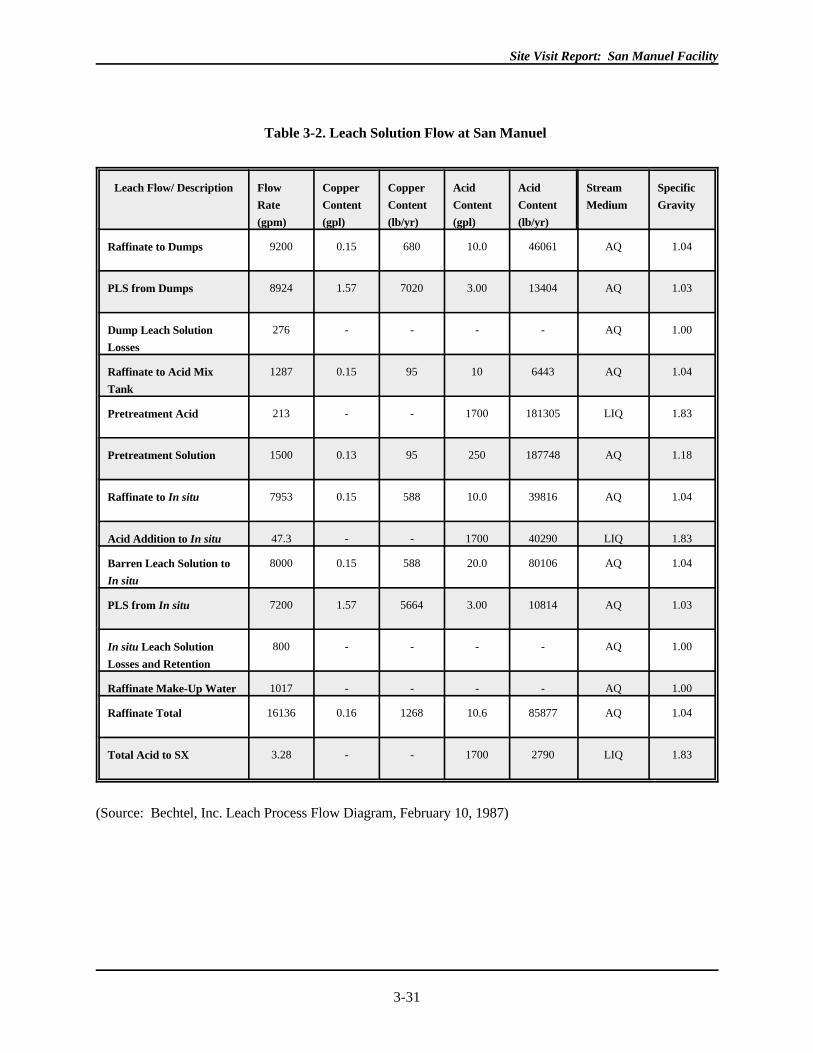
raffinate was recorded as 10.6 gpl, or 85,877 pounds per hour. (See Table 3-2) Combined solution loss from
the heap leach and in situ leach operations exceeded 1,000 gpm in 1987. The destination of lost solution was
not determined. According to the Arizona DEQ, the loss of raffinate (1000 gpm) may have been due to in
situ leaching not stabilizing, with solution diverting into cracks in the rock where flow is not recoverable.
Pregnant leach solution forms as the acid percolates through the pile and dissolves copper minerals; it flows
into drains and collection pipes beneath the pile. The collection pipes flow into lined ditches ranging from 16
to 22 feet wide and a minimum of 32 inches deep. The collection ditches extend alongside the heap, directing
pregnant solution through sediment traps to the Pregnant Leach Solution (PLS) Pond (Magma, 1988, 1992).
Sediment traps prevent 90 percent of material greater than No. 40 sieve from entering the PLS pond and must
be cleaned periodically to ensure continued effectiveness. Sediment removed from sediment traps is
deposited on the heap; quantities were not determined.
The heap leach facility was designed as a no-discharge operation, with the heap, its collection ditches, the
pregnant solution pond and plant feed ponds all lined to prevent solution loss. Perforated 3-inch diameter
drainage piping was installed at 20-foot intervals at the toe of the heap leach to facilitate PLS drainage to the
solution drainage ditches (Magma, 1991-APP). The expected life of the leach pad is approximately fifteen
years, while the life of the pond liners is not specified. Heap leach operations are expected to be discontinued
in 1996.
Solvent Extraction/Electrowinning Operation
The Solvent Extraction/Electrowinning plant (SX/EW) consists of the PLS pond, the plant feed pond, the
raffinate pond, and the SX/EW plant. The solvent extraction plant operates at an 18,000 gpm throughput
that yields up to 50,000 short tons of copper per year from the electrowinning plant. (Magma, 1991-APP)
Operations at the SX/EW began in 1986 with the beginning of oxide ore open pit mining. The PLS pond is
lined with an 80-mil HDPE liner overlying compacted subgrade material and has a 5-million gallon capacity.
Site Visit Report: San Manuel Facility
3-31
Table 3-2. Leach Solution Flow at San Manuel
Leach Flow/ Description Flow Copper Copper Acid Acid Stream Specific
Rate Content Content Content Content Medium Gravity
(gpm) (gpl) (lb/yr) (gpl) (lb/yr)
Raffinate to Dumps 9200 0.15 680 10.0 46061 AQ 1.04
PLS from Dumps 8924 1.57 7020 3.00 13404 AQ 1.03
Dump Leach Solution
Losses
276 - - - - AQ 1.00
Raffinate to Acid Mix
Tank
1287 0.15 95 10 6443 AQ 1.04
Pretreatment Acid 213 - - 1700 181305 LIQ 1.83
Pretreatment Solution 1500 0.13 95 250 187748 AQ 1.18
Raffinate to In situ 7953 0.15 588 10.0 39816 AQ 1.04
Acid Addition to In situ 47.3 - - 1700 40290 LIQ 1.83
Barren Leach Solution to
In situ
8000 0.15 588 20.0 80106 AQ 1.04
PLS from In situ 7200 1.57 5664 3.00 10814 AQ 1.03
In situ Leach Solution
Losses and Retention
800 - - - - AQ 1.00
Raffinate Make-Up Water 1017 - - - - AQ 1.00
Raffinate Total 16136 0.16 1268 10.6 85877 AQ 1.04
Total Acid to SX 3.28 - - 1700 2790 LIQ 1.83
(Source: Bechtel, Inc. Leach Process Flow Diagram, February 10, 1987)
Site Visit Report: San Manuel Facility
3-32
Berms surround the outside of the pond to prevent run-on of precipitation, and overflow wier ditches were
installed on the southeast corner of the existing leach dump that are designed to receive excess PLS or PLS
rainwater, and direct their flow to the subsidence area in the open pit. (Magma, 1991-APP)
Pregnant leach solution from the heap leach is directed to the PLS pond. References do not indicate the rate
at which pregnant leach solution enters the pond. From the PLS pond, PLS is directed to the plant feed pond,
where it is mixed with pregnant leach solution from the in situ operation. The plant feed pond has a ten
million gallon capacity and is lined with a 60 mil XR5 reinforced fabric liner placed on top of compacted
subgrade material. Berming around this pond is designed to reduce storm water runon and to contain the
maximum process volume in addition to precipitation from a 100-year/6-hour storm event. (Magma, 1991-
APP)
Two of three 4,800 gpm capacity pumps in the PLS pond are used to pump effluent from the PLS pond to the
plant feed pond via a 14-inch diameter stainless steel pipe. The 14-inch diameter pipes feed a 24-inch
diameter stainless steel manifold that discharges the PLS to two 18-inch diameter polybutylene pipelines.
The pipes flow into the SX/EW plant feed pond. The average concentration of sulfuric acid in solution
entering the pregnant leach solution pond and the plant feed pond is 19.12 gpl, with approximately 1.25 gpl
copper. (Magma, 1992b)
The solution extraction/electrowinning (SX/EW) operation recovers copper from the pregnant leach solution
(PLS). The PLS is subjected to a series of extraction and stripping stages that isolate the copper mineral to
produce an electrolyte for electrowinning. Electrowinning uses an electrical charge to plate metals to the
cathode. Concurrent with deposition of copper on the cathode, acid and oxygen are generated at the anode,
creating spent electrolyte solution. (Weiss, 1985)
Pregnant leach solution from the plant feed pond flows into the solvent extraction plant (SX) at a rate of
18,000 gpm. The SX plant has two parallel trains. Each parallel train has two extraction tanks and one
stripping tank. In the extraction tank, the pregnant solution is mixed with organic solution containing 95
percent kerosene (organic) and 5 percent of an unspecified chelating agent. The chelating agent in the organic
complexes with the metal ions and a density separation is allowed, where copper preferentially transfers from
solution in the aqueous phase to solution in the organic phase. After mixing, the solvent and aqueous
solutions separate, since they are immiscible. Copper-loaded organic then flows over wiers into a collection
system. Not all copper has been removed from the partially stripped leach solution, so it is routed to a second
extraction tank to be mixed again with barren organic. The loaded organic from the second extraction tank is
sent back to the first extraction tank as make-up organic to collect copper from the richer PLS. (The amounts
of reagents used in this operation were not determined.) In each train, loaded organic from the first extraction
tank flows from the collection system to the stripper tank. In the stripper cell, an electrolyte (spent electrolyte
from the electrowinning plant, as well as additional fresh electrolyte) is added in the mixer portion of the tank,
stripping the organic of the copper. Copper binds to the electrolyte, and is sent to the electrowinning plant
for final recovery of copper onto lead anodes. (See Figure 3-7)
Site Visit Report: San Manuel Facility
3-33
Figure 3-7. Solvent Extraction/Electrowinning
Site Visit Report: San Manuel Facility
3-34
(Weiss, 1985, Magma, 1992b)
Solvent extraction leads to periodic buildup of impurities in the organic tanks, including silt that may collect
on the bottom of the tanks. Magma "cleans" (or recycles) the organic by flooding off the organic and piping
it to a centrifuge. The centrifuge removes the "gunk" from the organic, then the organic is sent through a clay
filter to remove any remaining impurities. "Recycled" organic is sent to the second tank of solvent extraction
for mixing with partially loaded PLS. According to Magma representatives, gunk from the centrifuge as well
as spent clay from the clay filter, is collected and transported to the heap for leaching. It was not determined
how often this procedure is performed, nor the volumes of gunk or clay material generated. In addition, SX
tanks are periodically drained and accumulated silt is vacuumed off. It was not determined how the silt is
managed.
Once stripped of copper in the extraction tanks, the barren solution (raffinate) from the solvent extraction
tanks is routed to the 10 million gallon capacity raffinate pond where solution is recycled to the heap leach
and in situ leach operations by three 5300 gpm capacity pumps. Unlike the PLS and plant feed ponds, the
raffinate pond is not equipped with an overflow ditch. (Deming, April 1991).
The electrowinning operation at San Manuel has a total production capacity of 50,000 short tons per year,
twice what was produced when operations began in 1986. The electrowinning operation consists of rectifiers
that provide power to the electrowinning cells, and the cathode stripping machine (Magma, 1992b). The
rectifiers provide an output capacity of 1,000 to 18,100 amperes and 55 to 217 volts that are distributed to
the lead anodes. The EW facility contains four rows with 47 cells per row, with each cell constructed of
concrete and lined with flexible PVC, and rigid PVC buffer sheets. Sixty-one lead anodes and sixty stainless
steel mother blank cathodes are placed in each cell (Magma, 1992b). Small amounts of cobalt (from 0.5 to
1.0 pounds per ton of copper) are added to the electrolyte bath to maintain the integrity of the lead anodes.
The current is distributed to the lead anode and flows through the electrolyte to the cathode. Copper is plated
onto stainless steel plates to obtain concentrate that is 99.999% copper. The operation takes place over a 7-
day period, yielding 100 pound plates of copper. The loaded plates are removed from the bath and washed at
the cathode stripping machine to remove any residual electrolyte. Information on the amount of wash
solution waste generated during washing of the plates was not determined, nor was it determined how the
wash solution is managed. The cathode stripping machine also loosens the sheets from the stainless steel
blank, which is re-cycled for re-use in the electrowinning baths. Cathode copper sheets are transported to San
Manuel's Rod Plant or sold as sheets to customers (Magma, 1992b).
Reagent storage tanks are located in between the SX and EW operations, on a gunite surface sloped to
prevent runoff (Magma, 1992b). Magma lists monthly reagent usage of diluent (kerosene) at approximately
32,000 gallons, used at a rate of 6 to 10 gallons per ton of copper produced. Magma
Site Visit Report: San Manuel Facility
3-35
also lists a usage rate of 2500 gallons per month of an unspecified lixiviant ("Lix 984"). Approximately
2,800 pounds of cobalt sulfate are used per month at a rate of 0.5 to 1.0 pounds per ton of copper produced.
3.2.2 Sulfide Ore
Sulfide ore mined at San Manuel is chalcopyrite and is found in the one billion ton ore body. Sulfide ore is
extracted by underground mining, which had reached a depth of over 4,000 feet below the surface at the time
of the site visit. Beneficiation of chalcopyrite at San Manuel takes place at the mill facility and includes
crushing, grinding and flotation operations. Mining of the San Manuel ore body will continue until 1995
when it is expected to be depleted. Mining of the Kalamazoo ore body will continue for at least an additional
15 years. Development work at the Kalamazoo underground workings currently hauls ore at a rate of 10,000
tpd. A 15-year labor agreement was a prerequisite for developing the Kalamazoo ore body and that has
recently been concluded (Greeley, 1992).
3.2.2.1 Extraction
Since 1948, when underground mining began at San Manuel, over half of the one-billion ton ore body has
been mined using underground block-caving methods. Currently, 56,000 tpd is hauled to the surface and
transported to the mill. Magma is currently attempting to keep costs at San Manuel to less than $4/ton of ore
hauled. No additional information was obtained regarding costs of current operations or projected costs of
mining at San Manuel or Kalamazoo. Relatively little waste rock is generated from underground mining
compared to waste rock generated in the open pit. It was not determined where waste rock is placed in the
underground mine. As of 1987, the areal extent of the underground mine appeared to be approximately 0.4
by 0.7 miles, oriented below the southern half of the oxide open pit mine. (Magma, Undated Map, "Magma
Copper Minesite") (See Figure 3-3).
Underground mine workings are located between 700 and approximately 4,000 feet below the surface and are
accessed by four "production" shafts and three "service" shafts. The service shafts (Shafts 1, 4, and 5)
provide intake ventilation and supplies, while the production shafts (3A, B, C and D) are used to haul ore to
the surface as well as serving as exhaust shafts. The ventilation system circulates up to 1 million cubic feet
per minute of forced ventilation air into the underground mine workings. Production and service shafts range
in depth from 2,729 feet (shaft 4) to 4,123 feet (shaft 5). Shaft 4 is the main service shaft transporting
employees and supplies, as well as containing the primary compressed air lines and the in situ leaching pump
lines that return collected PLS to the surface for transport to the plant feed pond. Shaft 5 is a multipurpose
shaft that also provides access to the Kalamazoo ore body (Magma, 1988). Production and service shaft
activities at the mine site are monitored by computers in the mine surface control room.
The underground sulfide ore body is mined using the block-caving method, which entails blasting sections of
the ore body above the grizzly level and allowing gravity to collapse horizontal slices of ore (Magma, 1988).
Ore falls through the grizzly level and goes through a series of vertical or inclined shafts that transfer ore to
the haulage level into ore cars. At the grizzly level, very large pieces are reduced in size manually with a
Site Visit Report: San Manuel Facility
3-36
sledge hammer. The train of ore cars transfers the ore to dump pockets, where it is drawn up to the surface
with five ton skips to the top of the production shafts, and dropped into coarse ore storage bins (Magma,
1988).
Prior to transport to the mill, ore is subjected to primary crushing in one of four gyratory crushers located in
the underground workings. Iron detectors are installed on conveyors for the removal of tramp iron. The ore
is sent to receiving bins for transport to the mill in 100 ton capacity rail cars. Ore from the underground mine
is generally sized to less than six inches. In some cases, the coarse ore may be shipped directly to the mill
without primary crushing. A 20,000 ton coarse ore storage bin at the mill is used to store ore for holding
prior to secondary and tertiary crushing.
Ground water that infiltrates the mine workings must be pumped to the surface in order for underground
operations to proceed. Sumps are used to dewater the underground workings, pumping water through two
lines to the surface through shaft 1 (approximately 1,800 gpm) and shaft 2 (approximately 3,000 gpm).
Mine water is combined in a 24-inch steel pipe and stored in a one acre settling pond prior to storage in two
100,000 gallon holding tanks for subsequent use at the mill. (It was not determined if the settling pond is
lined.) Five 2,000-2,500 gpm pumps located adjacent to the holding tanks in the No. 3 yard area send water
to the mill. Each pump's operating status is monitored from the mine surface control center, and they are
inspected daily. (Magma, 1992) Dewatering in the underground mine workings has created a large cone of
depression in the area of the mine.
3.2.2.2 Beneficiation
Sulfide ore beneficiation at San Manuel takes place at the mill facility where ore is initially sized by crushing
and grinding. Both ore and slag are subjected to rougher and cleaner stages of flotation. According to
Magma representatives, all slag (including older slag piles), has been milled and concentrated in the flotation
circuit since 1974. The flotation concentrate is then sent to the molybdenite plant where by-product
molybdenite is recovered from the copper concentrate. The mill has the capacity to beneficiate 60,000 tpd of
ore producing 30 percent copper concentrate. (Magma, 1992c) The number of tons of molybdenite by-
product produced per day was not determined.
Crushing and Grinding
The first step in ore beneficiation is grinding. Ore from the coarse ore storage bins at the mill site is
conveyed to a double deck screen, where undersized material (< 1 inch) is conveyed to fine ore bins, while
oversized material (>1 inch) is sent to one of the cone crushers. The amount of ore sent to each grinding
circuit is monitored by a weightometer. (Magma, 1988) The cone crushers discharge to the surge bins. Ore
from the surge bins is conveyed to the single deck vibrating screen for further sizing.
Site Visit Report: San Manuel Facility
3-37
Fine material (<1 inch) from the single deck screen goes to the fine ore bins, and remaining oversized material
goes to another standard cone crusher for additional crushing. After final crushing, all material meets the
grinding circuit size requirements of minus one inch. (Magma, 1990)
The crushed ore is then conveyed at a rate of 3,500 tons per hour into one of 13 automated wet grinding
circuits, each with one rod mill and two ball mills. Water used in the grinding operations is pumped from
mine water surge tanks. The rate at which water enters the mill circuit from the mine water surge tanks was
not determined. Ten of the circuits consist of a 10 foot x 13 foot rod mill and two 10 foot x 10 foot ball
mills. The remaining three circuits include one 12 1/2 foot x 16 foot rod mill and two 12 1/2 foot x 14 foot
ball mills. The rod and ball mills are cylindrical vessels filled with the ore and steel rods or balls that rotate
on a horizontal axis grinding the ore. After initial grinding in the rod mills, ore is sent to a cyclone for sizing.
Greater than 3mm material (the cyclone underflow) is transported to the ball mills for additional grinding.
The hydrocyclone overflow, less than 3mm material, is transferred to the pulp distributor flotation feed.
Overall, the grinding circuits reduce the ore size to 80 percent passing 200 mesh. (Magma, 1990)
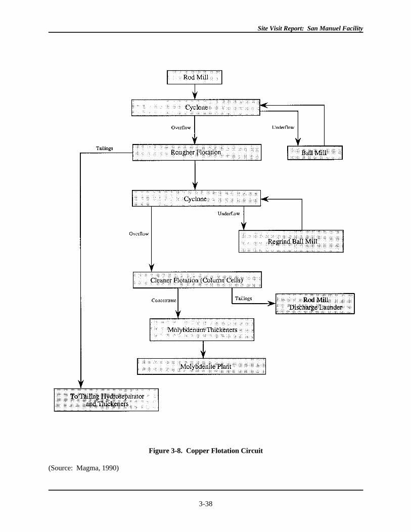
Copper Flotation
There are two separate, two-stage froth flotation systems, one for ore and another for slag and other materials
(e.g., refractory bricks). The incoming ore feed is 0.63 percent copper; the incoming slag feed is 1.8 percent
copper. There are eight flotation circuits in the mill at San Manuel, an unspecified number of which are
allocated to slag flotation. Approximately 56,000 tons of ore feed and 2,300 tons of slag are beneficiated at
the mill each day. Methylisobutyl carbonol (MIBC) is used as a frother in the flotation circuit. Collectors
include sodium xanthate, fuel oil (jet fuel A, which is used as a molybdenum collector), and VS M8, a
proprietary flotation agent containing carbon disulfide. The underflow is sent to the tailings thickener. The
two types of flotation circuits, one for ore and one for slag, are exactly the same except that a different
primary collector, Dithiophosphate 55741 (an American Cyanamid product), is used in slag flotation. (See
Figure 3-8)
Site Visit Report: San Manuel Facility
3-38
Figure 3-8. Copper Flotation Circuit
(Source: Magma, 1990)
Site Visit Report: San Manuel Facility
3-39
The eight flotation circuits include a total of ten 2,000 cubic foot rougher cells, and 143 rougher cells of
smaller dimensions (300 cubic feet). Cleaner flotation takes place in sixteen 39-foot high column flotation
cells that concentrate the ore to 30 percent copper. The overflow from rougher flotation (containing an
unspecified copper concentration) is transferred to a cleaner/column flotation stage in each circuit, while
underflow goes to Magma's tailings thickeners. In each circuit, the second stage of flotation occurs in the 39
foot high, 40 cubic feet cleaner/column cells. The overflow from cleaner cells is 30 percent copper and goes
to separate collection launders for transport to the molybdenite plant. The underflow goes to the ball mills
and is returned to the rougher for additional flotation.
Site Visit Report: San Manuel Facility
3-40
Tails from the rougher circuit are sent to the tailings hydroseparators. Tailings from the mill are typically 30
percent solids and after the thickeners, tailings are 53 percent solids. The quantity of tailings generated per
day was not determined. Approximately 400 million tons of tailings have accumulated in San Manuel's
tailings impoundments. (Helmer, 1992)
Molybdenum Plant
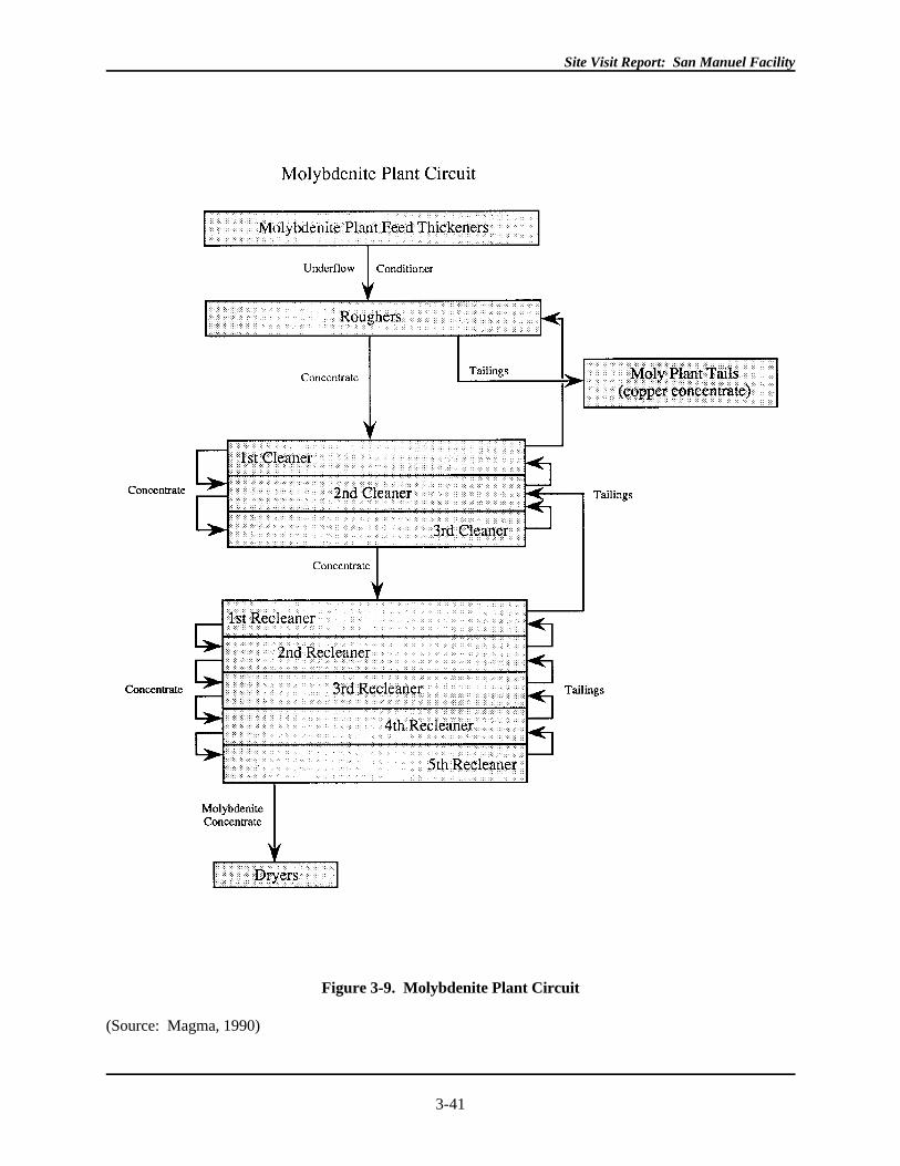
Copper concentrate from flotation contains approximately 1.0 percent molybdenum disulfide (molybdenite), a
concentration high enough to generate a saleable by-product. The molybdenite plant consists of additional
stages of flotation: one rougher stage, three cleaner stages, and five recleaner stages that separate the
molybdenum from the copper concentrate. (See Figure 3-9)
Site Visit Report: San Manuel Facility
3-41
Figure 3-9. Molybdenite Plant Circuit
(Source: Magma, 1990)
Site Visit Report: San Manuel Facility
3-42
The copper concentrate is first added to rougher flotation cells, where sodium cyanide is used to suppress
the copper (the quantity of sodium cyanide used per year was not determined). The molybdenum floats while
the copper concentrate becomes underflow or "tailings" and is sent to drying and thickening prior to smelting.
Overflow (the floated molybdenum concentrate) is sent on to three cleaner stages. Overflow from the last
cleaner stage is filtered, then "agitated," before being subjected to five more "special" flotation or recleaner
circuits. The percent of water filtered out during the recleaner stages was not determined. Overflow from
each recleaner stage passes on to the next recleaner flotation step, while underflow is returned to the previous
flotation cell for additional flotation. Overflow from the fifth recleaner circuit goes to the "splitter box" (not
further described), where about 70 percent is sent to filtering and drying. The remaining 30 percent of the
overflow from the last recleaner is returned to a filter at the beginning of the recleaner circuit. Filtering and
drying produces a 95 percent molybdenum disulfide product, which is shipped offsite in 55-gallon drums and
sold as molybdenite (Magma, 1990).
Copper Concentrate
Copper concentrate is dried in the "hydroseparator" (description not obtained), and dewatered to 10 percent
water. The water removed in the filtering/thickening operation is returned to the mill, and the dried copper
concentrate is placed on conveyor belts and transported to the flash furnace for smelting. The copper
concentrate consists of 30 percent copper, 30 percent iron, and 30 percent sulfur and oxidizes easily. In both
the dryer and on the conveyor, silica is added as flux for smelting. A total of 113 tpd of silica is used. The
amount of copper concentrate produced and the complete water balance for the mill were not determined.

Site Visit Report: San Manuel Facility
3-43
Site Visit Report: San Manuel Facility
3-44
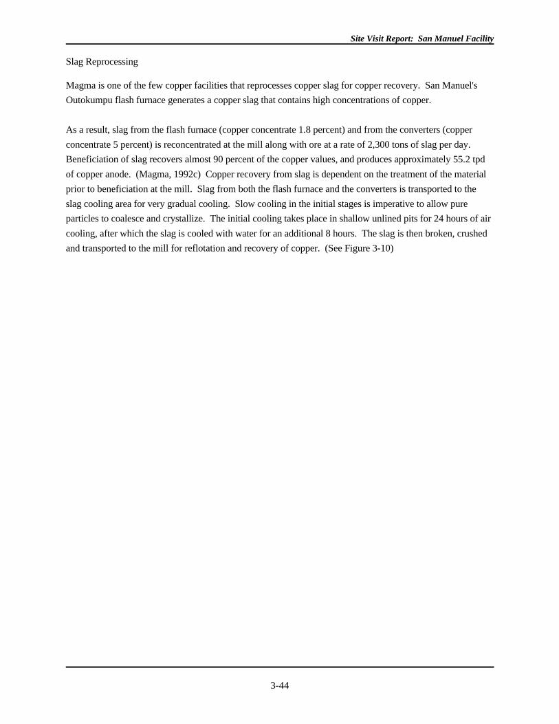
Slag Reprocessing
Magma is one of the few copper facilities that reprocesses copper slag for copper recovery. San Manuel's
Outokumpu flash furnace generates a copper slag that contains high concentrations of copper.
As a result, slag from the flash furnace (copper concentrate 1.8 percent) and from the converters (copper
concentrate 5 percent) is reconcentrated at the mill along with ore at a rate of 2,300 tons of slag per day.
Beneficiation of slag recovers almost 90 percent of the copper values, and produces approximately 55.2 tpd
of copper anode. (Magma, 1992c) Copper recovery from slag is dependent on the treatment of the material
prior to beneficiation at the mill. Slag from both the flash furnace and the converters is transported to the
slag cooling area for very gradual cooling. Slow cooling in the initial stages is imperative to allow pure
particles to coalesce and crystallize. The initial cooling takes place in shallow unlined pits for 24 hours of air
cooling, after which the slag is cooled with water for an additional 8 hours. The slag is then broken, crushed
and transported to the mill for reflotation and recovery of copper. (See Figure 3-10)
Site Visit Report: San Manuel Facility
3-45
Figure 3-10. Slag Reprocessing
(Source: Magma, 1992c)
Site Visit Report: San Manuel Facility
3-46
(Magma, 1992c)
Slag is transported to the cooling pits by Kress slag ladle carriers, rubber-tired, diesel-powered truck-like
vehicles that deposit one ladle at a time into each pit to form a layer 20 to 24 inches thick. Once the slag is
dry, bulldozers are used to break up the hardened material, and front end loaders place the ripped material
into dump trucks for transport to a portable crushing plant with a 24-inch grizzly and then on to the mill. The
slag is subjected to several stages of crushing and screening and sizing prior to being transported to the mill.
In the concentrator, flotation yields copper concentrate which is returned to the flash furnace feed. (Magma,
1992c)
Because all slag is reprocessed, there is not permanent disposal of slag at the Magma site. Slag pits are used
to allow cooling of the slag prior to crushing, flotation, and re-smelting. The slag pits are managed to avoid
storm water runon or runoff. Magma does not foresee a problem with potential release or transport of slag
constituents to the environment as the slag pits are located in an area 140 meters above the uppermost
useable aquifer, and the San Pedro River is located over 790 meters away. (U.S. EPA, July 1990)
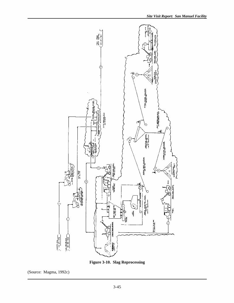
3.2.2.3 Processing Operations
Processing operations at San Manuel include the smelter, the associated acid plant, the electrolytic refinery,
and the rod casting plant (See Figure 3-11)
Site Visit Report: San Manuel Facility
3-47
Figure 3-11. Smelter Circuit at San Manuel
(Source: Magma, 1992m)
Site Visit Report: San Manuel Facility
3-48
. The San Manuel flash furnace is modeled after the Outokumpu design and has a processing capacity of 1
million tons of copper concentrate per year. During 1991, 703 million pounds of copper were produced by
the smelter, using concentrate from San Manuel as well as concentrate from Superior, Pinto Valley, McCabe,
and other mines. Approximately 520 million pounds of copper were produced from San Manuel ore.

Site Visit Report: San Manuel Facility
3-49

Site Visit Report: San Manuel Facility
3-50
Site Visit Report: San Manuel Facility
3-51
Flash Furnace and Converters
The copper concentrate from the mill consists of 30 percent copper, 30 percent iron, and 30 percent sulfur.
The reaction shaft of the smelter maintains a fire in the center of the stack initiated by natural gas, and
concentrate is sprinkled down around the sides. The sulfides react with oxygen to create a flash that melts all
the ingredients of the charge on their way down the 22-foot shaft into the settler. Gas containing dust and
nearly 30 percent sulfur dioxide is transported through the uptake shaft into a waste heat boiler for cooling.
The waste heat boilers remove heat from the gases for use in producing steam (Magma, 1988). The gases
continue through the electrostatic precipitators and on to the acid plant, which converts the sulfur dioxide-rich
gases to sulfuric acid (a usable and/or saleable product.)
Electrostatic precipitators recover molten dust particles contained in the flue gases. Flue dust from the flash
smelter furnace contains up to 25 percent copper. Fugitive dust emissions are also collected from the
converter. Fugitive dusts from the converter contain up to 80 percent copper. (Greenwald, 1992) The dust
from all three sources is then combined with fluxed, dried concentrate and sent back to the smelter. (Weiss,
1985)
Copper matte from the smelter contains approximately 63 percent copper and is placed in ladles and
transported to the "converter isle." The molten matte is poured into one of three converters, where further
oxidation of sulfur and slagging of waste metals takes place over a period of seven to eight hours, until the
matte reaches a purity of 99 percent copper. An estimated 1,390 tpd of matte is fed to the converters,
including 113 tpd of flux (silica) and 135 tpd of scrap copper. Copper matte is poured into empty cells in the
12- to 15-foot diameter converter. From the converters, the molten copper, now called "blister," is
transported to the casting department, where it is fire-refined for final removal of sulfur and oxygen before
being poured into molds to produce 820 pound anodes for transport to the electrolytic refinery. (Magma,
1988)
Acid Plant
The double absorption sulfuric acid plant receives sulfur dioxide rich gases from the flash smelting furnace
and converter furnaces (Magma, 1988). Approximately 45,600 standard cubic feet per minute (scfm),
containing 26 percent sulfur dioxide (SO ), is sent as off-gas from the flash furnace to the acid plant. The gas2
stream from the converter scrubber is also conveyed to the acid plant at a rate of approximately 70,000 scfm
per converter. The acid plant cleans, dries, and converts SO into saleable grade sulfuric acid by the addition2
of sulfur trioxide (SO ) (Magma, 1988). Sulfuric acid is produced at 93 percent and 98 percent purity. Acid3
plant blowdown is generated and is transferred via a pipeline to a mixer tank, where the blowdown is
combined with the tailings prior to being
deposited in the tailings ponds. The amount of acid plant blowdown generated from the acid plant, and
concentrations of its constituents prior to mixing with the tailings, was not determined.
Electrolytic Refinery
Site Visit Report: San Manuel Facility
3-52
At the electrolytic refinery, the anodes from the smelter, along with 13-pound copper starter sheets, are placed
in baths of an electrolyte made up of sulfuric acid and copper sulfate. There are 28 refining sections at San
Manuel's refinery. Each refining section includes 42 lined concrete cells that hold 46 anodes and 45 copper
starter sheets. An electrical current flows through the anodes and electrolyte to plate the copper from the
anodes onto the starter sheets (while hindering co-deposition of impurities) over a 12-day period. (Magma,
1988) After 12 days, the cathode produced weighs approximately 365 pounds.
Several residues are generated in the electrolytic refining operation. Residue falls out of solution, settling to
the bottom of the tanks. According to Magma, these residues are collected and leached to obtain their copper
content, while precious metals-containing slimes are filtered and dried for offsite precious metals recovery.
(Magma, 1988) Thirty-five thousand ounces of gold and 171,000 ounces of silver are produced per year in
this process. The electrolyte is generally recycled, however, an acidic wastestream is produced during
purification of the electrolyte that is mixed with tailings and discharged to the tailings impoundments.
Rod Casting Plant
From the electrolytic refinery, the cathode sheets are placed into a melting shaft at Magma's rod plant. The
molten copper is drawn on a wheel around the shaft and fed into finishing roles with cutting solution (95
percent water, 4 1/2 percent soluble oil, and isobutyl alcohol). The rod is reduced down to 5/16-inch in
diameter. The drawing process is also a continuous cooling process. The 5/16 diameter rods are sprayed
with sulfuric acid from the acid plant to remove oxide copper and are covered with a fine wax coating before
being sent to a continuous coiling machine and coiled at 6 miles per hour, or 36 to 40 tons per hour. Cooling
waters and rinse solutions used at this plant are recycled to the refinery, the mill, or within the plant.
Site Visit Report: San Manuel Facility
3-53
3.3 WASTE AND MATERIALS MANAGEMENT
3.3.1 Types of Wastes and Materials
Wastes managed onsite at the San Manuel facility include large volumes of waste rock, tailings, and other
wastes from extraction and beneficiation operations, as well as wastes generated from processing operations.
In addition, other materials, such as mine water, ore on leach pads, and leaching solutions, are managed
onsite. Because these materials ultimately become wastes when intended for disposal (when operations
cease), they are also addressed in this section.
This section emphasizes management of extraction and beneficiation wastes and materials, and the units in
which they are managed, as well as areas where processing wastes and materials are commingled with those
from extraction and beneficiation. Although processing is generally beyond the scope of this report, limited
information on these wastes and materials will be discussed below in order to characterize the material
balance throughout the facility.
3.3.2 Underground Workings, Open Pit, and In situ Leach Area
As described above, three separate operations take place at the mine site to extract and beneficiate copper
minerals from sulfide and oxide ores at San Manuel. Because underground mining, open pit surface mining,
and in situ leaching all occur in the same general vicinity, these units (pit, underground workings, etc.) and
the wastes and materials they generate are discussed together in this section. Generally, underground
methods mine the deeper area of the ore body (sulfide ore), while open pit methods are used to mine oxide ore
at the surface with in situ operations recovering copper from areas in-between. As a result of underground
mining, subsidence has intersected the open pit and in situ areas.
As described above, underground workings extend from 1,400 feet below the surface to the 4,080- foot level
where dewatering operations occur. The workings cover an approximate areal extent of 2,000 by 3,700 feet
(Magma, 1992h). (See Figure 3-4.) The main haulage level is currently at a depth of 2,875 feet.
Dewatering is of major importance to underground operations. Magma pumps approximately 3,440 gpm of
water to the surface to keep the workings free of infiltration. Water generated from the mine is stored in a
settling pond prior to being transported to the mill circuit (It was not determined whether this pond was
lined). Though the original level of the water table in the area of the mine was not provided, dewatering
operations at the time of the site visit were on-going at a depth of 4,080 feet. As of 1982, the water table
elevation one-half mile to the south east had dropped 800 feet due to mine pumping (Magma, 1991).
According to Magma representatives, dewatering operations have created an eight mile cone of depression in
the water table. According to the Aquifer Protection Permit for the leach pad, the cone of depression covers
approximately 11 square miles, surrounding the mine in all directions except to the south and southwest
where recharge occurs. EPA did not obtain information regarding original groundwater levels, water
elevation levels, or any changes that have occurred to these levels over the years.
Site Visit Report: San Manuel Facility
3-54
Underground mining generates relatively little waste rock at San Manuel. According to Magma
representatives, no waste rock from the underground is hauled to the surface. Additional details on the
quantity and management of waste rock underground was not obtained.
Located in the subsidence area above the underground mine, the open pit has currently reached a depth of 800
feet, with an additional 400 feet remaining before reaching a final depth of 1,200 feet. The approximate areal
extent of the open pit is 5,000 feet by 4,400 feet (Magma 1992i). During the site visit, EPA observed
underground mining subsidence features at the edge of the pit and in the waste rock piled at an angle of
repose into the pit. In addition, EPA observed in situ mining within the pit, showing the close proximity of
activities at the mine site. During EPA's site visit, the pit appeared relatively dry. Open pit mining at San
Manuel generates from 60,000 to 70,000 tons of waste rock per day with a stripping ratio (ore:waste rock)
that ranges from 1:1.3 to 1:2. Waste rock is disposed of in one of several waste rock dump piles onsite.
These are discussed in the Waste Rock section below.
Magma extracts copper from the ore in the areas between the open pit and the depleted portion of the
underground mine using in situ leaching techniques. Approximately 272 million tons of ore rubbleized by
underground block caving methods is subjected to in situ leaching (Magma, 1988). According to Magma,
approximately 2 billion gallons of raffinate solution was held within the ore at the time of the site visit. The
pregnant solution is collected in specific panels of the underground workings, or captured by submersible
sumps, and pumped to the surface to the plant feed pond. Copper production from the in situ operation was
not fully operational until the ore body was completely saturated (when this occurred was not determined).
Initially, raffinate from the SX process was sent to the in situ wells at a flow rate of 8,000 gpm (gpm). The
rate of PLS recovery in the underground panels measured 7,200 gpm, a solution loss of 800 gpm to
surrounding ore and country rock (See Table 3-2). Current injection rates are 3,000 gpm, or 21,600 tpd. The
number of injection wells used and the extent of the area subject to the in situ leaching operation were not
determined.
According to Magma's APP for the Leach Pad, "because of the cone of depression, mine pumping removes
any precipitation infiltrating the mine area, the recharge of groundwater passing through the area, all spillage,
leakage or injection above the area, and ambient groundwater present within the mine. As long as Magma
maintains this cone of depression, it is hydrologically impossible for ambient groundwater outside the mine to
become impacted by mine operations." No information was obtained on actions that may be taken when the
underground mine operations cease and dewatering stops.
3.3.3 Waste Rock
The open pit mine is the source of most of the waste rock generated at San Manuel (60,000 to 70,000 tons of
waste rock per day). Approximately 20 million tons of waste rock have been generated each year. Based on
that estimate, roughly 131 million tons of waste rock may be contained in the three waste rock piles on-site
(based on 60,000 tpd, 365 days per year for 6 years) (See Figure 3-12)
Site Visit Report: San Manuel Facility
3-55
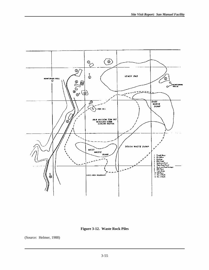
Figure 3-12. Waste Rock Piles
(Source: Helmer, 1988)
Site Visit Report: San Manuel Facility
3-56
. Limited information on waste rock piles 1,3, and 4 was obtained. The Agency does not have data on waste
rock pile number 2.
Waste dump no. 1 is located on the northeast edge of the pit. The pile is approximately 3,200 feet in length,
with two lobes extending as far east as 1,900 feet from the pit (Magma, 1992i). According to Magma
representatives, this was the original waste rock pile formed during the excavation of the pit. Magma
reported that no waste rock had been deposited in this waste rock pile in over two years, as all waste rock
generated in this time period had been used to backfill the subsidence area in the open pit. Waste dump no. 3,
as labeled on Figure 3-12, measures approximately 1,200 by 500 feet and is also located southwest of the pit,
opposite waste rock dump no. 4. (Magma, 1992i)
Waste dump no. 4 is located on the southwest edge of the pit and is currently active. Here, the waste rock is
dumped back into the pit, and left to fall at an angle of repose inside the pit. Based on Figure 3-12,
dimensions of this waste rock pile are approximately 300 feet by 2400 feet. No information was obtained on
the acid generating potential, if any, of these waste rock piles, nor were details on specific runon and runoff
controls or monitoring of the waste rock piles.
3.3.4 Dump/Heap Leach and SX/EW Plant
As discussed previously, the heap leach operation entails the beneficiation of oxide ore from the open pit by
leaching copper with sulfuric acid to produce a pregnant leach solution, which is then sent to the SX/EW.
This operation involves recirculation of a sulfuric acid solution through a series of tanks, ponds, and ore (both
in situ and on the heap) to extract copper. Units associated with this operation include the lined heap and
collection ditches, the lined pregnant leach solution and plant feed ponds, the raffinate pond, and the SX/EW
plant. The raffinate (barren leach solution) is also used in the in situ mining operation discussed above.
Although the materials generated are not wastes during the time leaching continues, they are discussed here
because the toxic constituents that are handled in the operations and/or that occur in the materials present
some potential for environmental contamination.
3.3.4.1 Heap Leach
The heap leach operation was designed as a no-discharge operation, with the heap, its collection ditches, the
pregnant solution pond, and plant feed ponds all lined to prevent solution loss.
Site Visit Report: San Manuel Facility
3-57
The heap has been constructed on a pad near the open pit mine. The heap leach pad is approximately 3,000
feet wide by 6,000 feet long, covering 230 acres (Magma, 1989). According to Magma representatives, the
leach pad is underlain by Gila Conglomerate with a permeability of 3.3 X 10 . -7
Soils beneath the leach pad were compacted and a 7-1/2 ounce per square yard layer of geotextile material
liner was installed prior to laying the leach pad. Initially, three thicknesses of HDPE liners were used to make
up the original 113-acre leach pad: a 60 mil HDPE lined 71 acres; a 100 mil HDPE lined 17 acres; and a 40
mil HDPE lined the other 25 acres. Apparently, 60 mil liners were used over ridges of the heap, while 100
mil liners were used to line collection ditches. Eighteen inches of gravel were placed on top of the liner to
prevent tearing and a collection system of perforated pipes was installed to prevent pooling. (State of
Arizona, 1989) Run-of-mine oxide ore from the open pit is hauled to the heap leach at a rate of
approximately 30,000 tpd. The heap is rising in 15-foot lifts. Current estimates by Magma state that the
heap leach will reach a maximum height of 400 feet, (almost 100 feet higher than described in the 1989
Groundwater Quality Protection Permit).
After being collected in ditches along the side of the heap, the solution is sent to the PLS pond (5- million
gallon capacity) and on to the plant feed pond (10-million gallon capacity). Both ponds are lined: the PLS
with 80 mil HDPE overlying compacted subgrade material, and the plant feed with 60 mil XR5 reinforced
fabric liner overlying compacted subgrade material. After being stripped of copper in the SX/EW plant,
barren solution (raffinate) is sent to the raffinate pond (capacity 10 million gallons). The raffinate pond is
lined with a 60 mil XR5 reinforced fabric liner overlying compacted subgrade material. Each of the three
ponds is designed to contain a 100-year/six-hour storm event (3.4 inches of precipitation), in addition to
working solution.
At heap closure (expected in 1996), the leached ore will remain on the pad (the amount was not determined).
According to the APP, closure will entail rinsing of the heap by "natural meteoric events," with no cover or
reclamation planned. Magma plans to collect the solution generated by natural meteoric events and send it to
the SX/EW plant. The ponds and the SX/EW are scheduled to continue operating until closure of the entire
facility, possibly for an additional 35 to 40 years, supplied in part with pregnant solution from the in situ
mining operation. Specific details on life of pond liners or plans for replacing the liners were not obtained,
nor were anticipated flow rates from the heap after application of lixiviant ceases. There are apparently no
"trigger levels" established for determining the point at which leachate collection will no longer be required.
Although the heap leach operation was designed as a no-discharge operation (with the heap, its collection
ditches, the pregnant solution pond, and plant feed ponds all lined to prevent solution loss), solution losses
from the heap to undetermined sources (e.g. evaporation) during 1987 were estimated to be 276 gpm. The
application rate of barren solution to the heap at that time was 9200 gpm. The 1989 application rate was
14,500 gpm. According to Magma, any solution released will not impact ambient groundwater during
operation of the mine, due to mine pumping and the associated cone of depression (Magma, 1991-APP).
Site Visit Report: San Manuel Facility
3-58
According to Magma representatives, the heap may periodically be used as a disposal area since most spills
that occur at the mine site may be dug up and transported to the heap for leaching. Also, "gunk" generated at
the solvent extraction facility is centrifuged and deposited on the heap for leaching of residual copper.
Magma Copper has received an Aquifer Protection Permit from the State (Arizona Department of
Environmental Quality, ADEQ). Magma has accordingly monitored groundwater with one well, and the
vadose zone with 2 wells. According to Magma personnel, the well is currently upgradient rather than
downgradient of the heap due to the cone of depression caused by dewatering the mine. The rationale for this
approach is not clear. Monitoring results and other details of this program are presented in Section 4 below.
3.3.4.2 Solvent Extraction/Electrowinning Wastes
As described above, solvent extraction is a two-stage operation that selectively removes copper from leach
solution using a concentrated organic (kersosene), which is then stripped of copper by a strong electrolyte to
prepare a higher grade copper solution for electrowinning. Electrowinning then recovers copper from the
electrolyte by plating the copper onto lead anodes. The solvent extraction tanks are located outside of the
electrowinning building and are covered with roofs to diminish evaporation of solutions in the open tanks.
All solutions (leaching, organic, and electrolyte) are reused in the operation. Electrolytic solutions decrease in
effectiveness over time due to an accumulation of impurities. The method used to remove impurities from
spent electrolyte and any wastes generated by this operation, were not determined. A monthly reagent use
information sheet provided by Magma indicates that 32,000 gallons of organic are used per month. It is
unclear whether this number refers to consumption or to the total amount used and recycled. A certain
volume of organic is assumed to be lost to evaporation. The organic is directed through a centrifuge and clay
filter to remove impurities prior to reuse. "Gunk" (the material removed by the centrifuge) and spent clay
from the filter is placed on the heap for leaching of residual copper values. The quantity of gunk generated
was not determined.
Silt may accumulate on the bottom of the tanks over time. According to Magma representatives, the silt is
removed by vacuum. The volume of silt generated, and its method for disposal, were not determined; it may
be deposited on the heap for additional leaching.
At the electrowinning facility, completed copper cathodes are washed with water to remove residual
electrolyte from the sheets. The amount of wash water generated in this operation and its disposition were
not determined. Waste lead anodes (quantities unknown) are sent to a Doe Run lead smelter. Information on
the generation of sludge or other residues from the electrowinning facility was not obtained.
3.3.5 Tailings Impoundments
3.3.5.1 Tailings
Site Visit Report: San Manuel Facility
3-59
At San Manuel, tailings are generated during the initial copper-molybdenum flotation circuits, prior to the
separation of the molybdenum from copper in the moly-plant. Tailings are comprised of gangue (nonvaluable
materials) from the ore, water, and remnants of reagents used during the flotation operation. Slag tailings are
comprised primarily of silicon, iron, magnesium, sodium, smaller amounts of copper, lead and zinc, as well as
other trace elements (U.S. EPA, 1990). According to Magma personnel, typical copper concentrates in the
rougher tailings are .07 to .08 percent. An analysis of copper mill tailings prior to disposal into
Impoundment no. 10 found the following concentrations of constituents (ppm): arsenic, 6; cadmium, 1.1;
chromium, 6; lead, 11; copper, 298; cyanide, <5; mercury, <0.005; nitrogen, 10; sodium, 1,400; selenium,
<0.05; and zinc, 1,000. (Magma, November 21, 1990) It is not clear whether the sample was obtained prior
to or after the tailings reached the mixing area where Magma combines acid plant blowdown with the tailings.
According to the Arizona DEQ, Magma's tailings flow through the mixing area at a rate of approximately
1600 gpm with approximately 50 percent solids; acid plant blowdown is combined with the tailings at a rate
of approximately 400 gpm.
Tailings are generated at each of the eight flotation circuits in the concentrator and are fed to a
hydroseparator. Underflow from the hydroseparator is sent to a repulper and on to the tailing distributor to
various tailings dams. Overflow of the hydroseparator is directed to the tailings thickeners, where water is
removed for reuse during flotation, and underflow is sent to the repulper and on to tailings distribution
(Magma, 1990). Slag tailings are co-generated with ore tailings, making up approximately 0.3 to 2.6 percent
of the total tailings managed in the ponds (U.S. EPA, 1990).
3.3.5.2 Tailings Impoundment Construction and Reclamation
Thickened tailings (50 percent solids) are transported via a pipeline, flowing at an unspecified rate, from
tailings thickeners to one of seven tailings impoundments which cover a total of 3,600 acres. Five of the
seven tailings ponds are currently active. The two inactive ponds have a 50-million ton capacity still
available. Magma reclaims water from the tailings impoundments, although the volume (and proportion) of
water that is reclaimed to the mill was not determined. The tailings pond area is located west of the San
Pedro River, with Tailings Impoundment 10 reaching to within one-half mile of the River. There have been
at least three spills of tailings from the impoundments. These are described in Section 4.
At the unlined tailings impoundments, several hundred hydrocyclones are used to separate the coarse from
fine tailings during tailings deposition. These devices are spaced at 52-foot intervals along the berms of the
tailings impoundments. The coarse fraction is used to construct the berms and the finer material is pumped
further into the impoundments. Due to the natural slope of terrain upon which the tailings impoundments
were built, from the mill facility down to the River, the impoundments vary in height at their upper ends from
0 to 150 feet at the dams (US EPA, 1986, Weiss, 1985). (See Figure 3-3) Their ultimate height was not
determined.
In constructing the tailings impoundments, starter dams were keyed into the bedrock for stability. The key-
ways were built at right angles to the berm and cut to an unspecified depth, until they reached solid ground.
Site Visit Report: San Manuel Facility
3-60
The key-ways were filled with sand and clays from the surrounding areas, with the remainder of the starter
dams built using alluvial materials. In order to prevent storm water runoff from impacting the capacities of
the impoundments, Magma diverted major washes located upslope in the area around the impoundments. For
instance, Courthouse Wash was diverted around tailings impoundment no. 10. The mill division inspects the
tailings systems regularly to identify and correct any problems associated with its operations (Magma, 1992).
There is no formal groundwater monitoring program currently in place to monitor groundwater in the area of
the tailings impoundments. As discussed previously, there are 11 water supply wells installed at the foot of
the tailings impoundments (See Figure 3-3). Water from these wells has been shown to contain elevated
fluoride levels. However, no information on the source of the high fluoride levels was obtained. According to
Magma representatives, vegetation density has increased in the area between the tailings impoundments and
the river since the 1950's.
3.3.5.3 Tailings Reclamation
Although not required by any State or Federal law, Magma has initiated a tailings reclamation program in
response to public complaints regarding windblown tailings in the area. Magma is trying different
reclamation techniques on portions of impoundments 1 and 2. These impoundments cover 660 acres and
have been partially covered with native soils (Gila conglomerate) and vegetation. Approximately 420 acres
have been reclaimed using several reclamation techniques, with soil capping proving to be the most
successful. A total of 230 acres of flat tailings and 115 acres of sloped tailings have been capped with
borrow material. Approximately 70 acres of raw tailings are being used as a test plot. [For soil capping and
hydroseeding, the cost per acre was $2,420. The revegetation of raw tailings cost $1,217 per acre. The total
cost to reclaim 260 acres was $412,000. To stabilize an additional 160 acres at tailings impoundments 1 and
2, the cost is estimated to be $463,598 (Magma, 1992j). Once seeded, the soil cap and growth of vegetation
on the tailings has minimized erosion. Sewage effluent and sludge are also applied to the tailings near the
reclamation areas and appear to have had a positive effect on plant growth.
3.3.5.4 Co-mingling of Wastes in the Tailings Impoundments
Acid Plant Blowdown
In addition to tailings from the mill, Magma disposes of other wastes in the impoundments. At San Manuel,
acid plant blowdown is mixed with tailings and discharged to the tailings impoundment. Magma indicated
that mixing with the tailings serves to dilute or neutralize the acid plant blowdown before it enters the tailings
impoundments. Acid plant blowdown is discharged from a pipe to a cement tank-like structure and allowed
to mix with the tailings as the mixture flows through pipes to the tailings impoundments. According to the
Arizona DEQ, Magma's tailings flow through the mixing area at a rate of approximately 1600 gpm with
approximately 50 percent solids; acid plant blowdown is combined with the tailings at a rate of
approximately 400 gpm.
Site Visit Report: San Manuel Facility
3-61
Refinery Wastewater
According to Magma representatives, tailings are also used to neutralize acidic wastewater generated at the
electrolytic refinery. At the electrolytic refinery, anodes produced from blister copper are placed in baths of
acidic copper sulfate, and a current is applied that deposits copper from the anode onto the cathodes.
Impurities from this process either dissolve in the electrolyte or fall to the bottom of the tank to form a slime.
These slimes consist of suspended materials that may include precious metals. San Manuel manages this
residue by sending the slimes to precious metals recyclers for recovery of the values. An acidic waste stream
of process wastewater is also generated at the electrolytic refinery. This waste stream is added to the tailings
slurry and recycled in the mill water reclaim system. The amount of acidic process wastewater generated
from the electrolytic refinery was not determined and no information was obtained describing its
characteristics.
Other Wastes
Magma has set aside an area on the northwestern edge of tailings ponds 3 and 4 for disposal of acid or fuel
oil-contaminated soils from on-site spills. Under the Clean Water Act, San Manuel developed a Spill
Prevention Control and Countermeasure (SPCC) Plan to reduce the potential for discharge of oil at San
Manuel (Magma, 1992g). A 1990 SPCC Plan provided by Magma describes 11 oil or fuel spills that
occurred between October 1989 and October 1991. Wastes generated during clean up of these spills were
disposed of in the tailings impoundment or sent to asphalt contractors for use as input into an asphalt plant.
(Magma, 1992g; Deming, 1989)
3.3.6 Other Waste
3.3.6.1 Landfill
The San Manuel mine site includes a landfill. No information was obtained on the dimensions of the landfill
or the volume or types of materials disposed of there. According to Magma representatives, labeled and
bagged asbestos waste was disposed at the landfill. The asbestos was buried and the landfill was expanded to
cover the area of burial.
3.3.6.2 Sewage
Magma operates a sewage treatment plant for the plant site and for the town of San Manuel. Wastewater
from this system is discharged to the tailings ponds for evaporation. According to the 1989 Groundwater
Quality Protection Permit, discussed in more detail below, domestic sewage has to be disposed of in existing
septic tanks and leach trenches. Sewage wastewater from the town of San Manuel is discharged to the
tailings impoundments; the amount was not determined.
3.3.7 Waste Minimization
Site Visit Report: San Manuel Facility
3-62
Because San Manuel is an integrated facility, Magma recycles and reuses many materials onsite or sends
them offsite to recover material values. Table 3-3 provides a list of the materials at San Manuel that are
managed to minimize disposal.
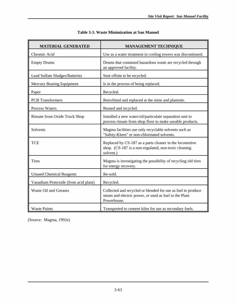
Site Visit Report: San Manuel Facility
3-63
Table 3-3. Waste Minimization at San Manuel
MATERIAL GENERATED MANAGEMENT TECHNIQUE
Chromic Acid Use as a water treatment in cooling towers was discontinued.
Empty Drums Drums that contained hazardous waste are recycled throughan approved facility.
Lead Sulfate Sludges/Batteries Sent offsite to be recycled.
Mercury Bearing Equipment Is in the process of being replaced.
Paper Recycled.
PCB Transformers Retrofitted and replaced at the mine and plantsite.
Process Waters Reused and recycled.
Rinsate from Oxide Truck Shop Installed a new water/oil/particulate separation unit toprocess rinsate from shop floor to make useable products.
Solvents Magma facilities use only recyclable solvents such as"Safety-Kleen" or non-chlorinated solvents.
TCE Replaced by CS-187 as a parts cleaner in the locomotiveshop. (CS-187 is a non-regulated, non-toxic cleaningsolvent.)
Tires Magma is investigating the possibility of recycling old tiresfor energy recovery.
Unused Chemical Reagents Re-sold.
Vanadium Pentoxide (from acid plant) Recycled.
Waste Oil and Greases Collected and recycled or blended for use as fuel to producesteam and electric power, or used as fuel in the PlantPowerhouse.
Waste Paints Transported to cement kilns for use as secondary fuels.
(Source: Magma, 1992e)
Site Visit Report: San Manuel Facility
3-64
3.4 REGULATORY REQUIREMENTS AND COMPLIANCE
The San Manuel facility is subject to both Federal and State regulatory requirements and their attendant
permits. A list of Magma's permits for the San Manuel facility is presented in Table 3-4. Only the
Groundwater Quality Protection Permit and the Aquifer Protection Permit for the Heap Leaching Facility,
both issued by the State of Arizona, were examined during preparation of this report. San Manuel is located
on private and State land; as no Federal land is involved, Federal land-managing agencies (e.g., Forest
Service, Bureau of Land Management) do not have jurisdiction over the facility. The majority of
requirements and permits are implemented by the State of Arizona and are described below.
3.4.1 Federal Permits
3.4.1.1 Clean Water Act
NPDES Permit
EPA has not delegated Federal authority to the State of Arizona to implement the requirements of the NPDES
program under the Clean Water Act. Although there have been NPDES issues at the site, EPA Region IX has
not issued a NPDES permit for the San Manuel facility. In December 1987, EPA conducted an inspection of
the site to determine if the facility required an NPDES permit to control surface mining and process water
discharges to area dry washes and to the San Pedro River. No discharges from the ponds at the heap leach
operation were found. However, evidence of a discharge of solution from the heap was noted. The discharge
area was discolored and eroded and extended to the Little Mammoth Wash. EPA Region IX recommended
that Magma apply for an NPDES permit to cover the above described discharge as well as discharge of
process water to Tucson Wash from a reservoir under construction at the time of inspection. Magma applied
for two discharge permits under NPDES on February 16, 1988. According to Magma representatives, the
area impacted was covered with an additional phase to the heap leach. According to Region IX, San Manuel's
NPDES permit is still in draft form.
Storm Water Group Application
Under the NPDES Storm Water Final Rule (55 FR 47990), active and inactive mine facilities (SIC codes 10-
14) discharge storm water associated with industrial activity. As such, mines are required to obtain an
NPDES permit that covers contaminated storm water discharges.
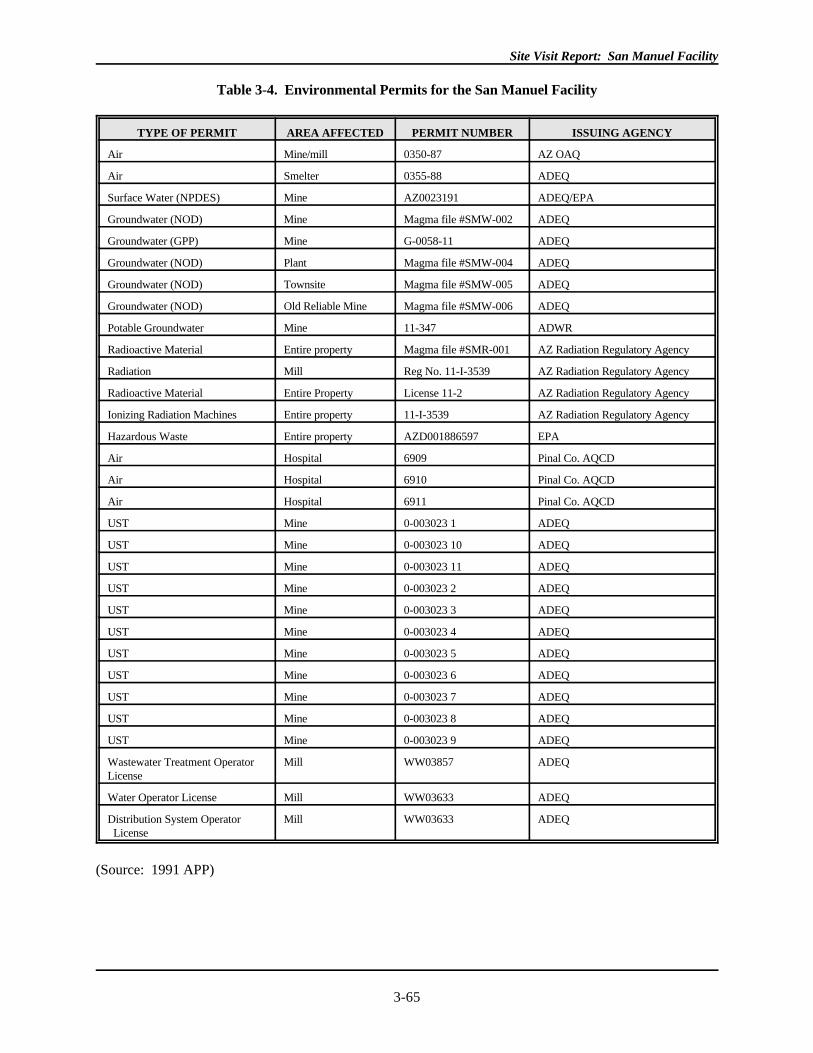
Site Visit Report: San Manuel Facility
3-65
Table 3-4. Environmental Permits for the San Manuel Facility
TYPE OF PERMIT AREA AFFECTED PERMIT NUMBER ISSUING AGENCY
Air Mine/mill 0350-87 AZ OAQ
Air Smelter 0355-88 ADEQ
Surface Water (NPDES) Mine AZ0023191 ADEQ/EPA
Groundwater (NOD) Mine Magma file #SMW-002 ADEQ
Groundwater (GPP) Mine G-0058-11 ADEQ
Groundwater (NOD) Plant Magma file #SMW-004 ADEQ
Groundwater (NOD) Townsite Magma file #SMW-005 ADEQ
Groundwater (NOD) Old Reliable Mine Magma file #SMW-006 ADEQ
Potable Groundwater Mine 11-347 ADWR
Radioactive Material Entire property Magma file #SMR-001 AZ Radiation Regulatory Agency
Radiation Mill Reg No. 11-I-3539 AZ Radiation Regulatory Agency
Radioactive Material Entire Property License 11-2 AZ Radiation Regulatory Agency
Ionizing Radiation Machines Entire property 11-I-3539 AZ Radiation Regulatory Agency
Hazardous Waste Entire property AZD001886597 EPA
Air Hospital 6909 Pinal Co. AQCD
Air Hospital 6910 Pinal Co. AQCD
Air Hospital 6911 Pinal Co. AQCD
UST Mine 0-003023 1 ADEQ
UST Mine 0-003023 10 ADEQ
UST Mine 0-003023 11 ADEQ
UST Mine 0-003023 2 ADEQ
UST Mine 0-003023 3 ADEQ
UST Mine 0-003023 4 ADEQ
UST Mine 0-003023 5 ADEQ
UST Mine 0-003023 6 ADEQ
UST Mine 0-003023 7 ADEQ
UST Mine 0-003023 8 ADEQ
UST Mine 0-003023 9 ADEQ
Wastewater Treatment Operator Mill WW03857 ADEQLicense
Water Operator License Mill WW03633 ADEQ
Distribution System Operator Mill WW03633 ADEQ License
(Source: 1991 APP)
Site Visit Report: San Manuel Facility
3-66
According to Magma representatives, San Manuel was included on the Part I Storm Water Group Application
submitted to EPA by the American Mining Congress (AMC). However, AMC's group application,
identification code number 570, did not include the San Manuel site. No further information was obtained.
3.4.1.2 Resource Conservation and Recovery Act
EPA has issued to Magma a hazardous waste identification number, Number AZD001886597, which
addresses the entire property. According to the Arizona DEQ, Magma is a large quantity generator. The
facility does not have a RCRA treatment, storage and disposal permit.
3.4.2 State of Arizona Permits
The Arizona Department of Environmental Quality's Office of Water Quality and Office of Air Quality are
responsible for issuing various permits applicable to mining operations. The Office of Water Quality is
responsible for administering Arizona's Water Quality Control Law, a part of Arizona's Environmental
Quality Act (AEQA, 1986), and its applicable permitting programs. The aquifer protection permit program,
administered by the Office of Water, was established to regulate point source discharges to groundwater.
This office previously issued Groundwater Quality Protection Permits (GWQPP), the predecessor of the
APP. The Office of Water Quality also conducts inspections for compliance with the GWQPP and the APP,
as well as handling violations of surface and aquifer water quality standards and other water quality rules.
3.4.2.1 Groundwater Quality Protection Permit (GWQPP)
In 1989, Magma was issued a Groundwater Quality Protection Permit (Number G 0058-11) for the operation
of its San Manuel Mine by ADEQ. The permit states that it is "valid for the operational life" of the facility,
provided that no conditions of the permit or of the applicable groundwater quality standards and aquifer
water quality standards are violated. (The GWQPP was the predecessor to the APP. Magma applied for the
APP in 1991, as described below).
The permit requires the facility and later expansions of the facility to be constructed and maintained to
prevent discharge of pollutants to the land surface or sub-surface which may adversely impact groundwater
quality. The facility and later expansions must include the following: the use of the heap leach process,
components of which include an impervious lined leach pad; impervious lined solution collection channels;
three (3) impervious lined solution ponds; leach solution transmitting lines; solvent extraction plant; tank
farm; and electrowinning plant.
The GWQPP also contains monitoring requirements and record-keeping requirements, including the
monitoring of leach solution used in the hydrometallurgical heap leach process, sampling, and analysis on an
annual basis of the pregnant leach solution (PLS) drainage into the PLS for major cations, anions, total
dissolved solids (TDS), and trace elements. Raffinate and PLS were to be sampled and analyzed for specified
Site Visit Report: San Manuel Facility
3-67
substances daily. Records pertaining to these monitoring activities and results and the daily levels of solution
in the PLS Pond, the plant feed pond, and the raffinate pond were not obtained.
3.4.2.2 Aquifer Protection Permit (APP)
On February 20, 1991, Magma applied for an Aquifer Protection Permit for the mine site. The permit was
issued on June 3, 1991 and applies to the existing heap leach and SX/EW facilities, to a 35.5-acre expansion
of the heap leach and to realignment of raffinate and preconditioning solution transmitting pipelines. A
modification to this APP was requested, and granted, in 1992, to increase the heap leach expansion an
additional 10.5 acres. At the time of the site visit, Magma was in the process of completing their APP
application for the remaining units at the site that were not included in the APP. Operations to be included in
the upcoming application include the tailings impoundments, the open pit mine, the in situ injection holes, the
underground sulfide mine, and surface facilities (such as ore crushing operations and assorted shops).
According to the Arizona DEQ, this information was due to the State on December 1, 1992.
Under the Aquifer Protection Permit Rules, promulgated under the AEQA, any person who owns or operates
a facility that discharges must obtain an individual APP. Mining facilities are considered discharging
facilities and are subject to permitting if the sites operate with any surface impoundments, solid waste
disposal, injection wells, tailings piles or ponds, leaching operations, wastewater treatment facilities, addition
of pollutants to underground caves or mines, or any point source discharges to navigable waters. Mining-
related activities exempt from being subject to this permit include mining overburden returned to the
excavation site, which has not been treated with any chemicals or leachate agent, and mines that closed prior
to January 1, 1986 (State of Arizona, APP Rules, 1989).
Design and Performance Standards
Arizona's APP sets requirements for Best Available Demonstrated Control Technology (BADCT) at
permitted facilities. At San Manuel, the heap leach pads, ponds and solution ditches, storage tanks, and
electrowinning tanks all meet BADCT requirements under the permit. For the heap leach pad, 80 mil HDPE
liners must be covered with 18 inches of protective gravel. Geotextile liners must also be installed in areas
used for internal drainage, and underneath the toe berms. Expansions of the heap pad must include
preparation of the subgrade to a range of maximum dry density from 90 percent in areas that receive less
leach dump overburden, to 95 percent maximum dry density in areas where the heap height will be more than
100 feet. All leach pad seams must be oriented to minimize stress in the joint areas, and must be tested to
demonstrate impermeability. Outer collection ditches are constructed of 80 mil HDPE liner over compacted
subgrade as well.
The PLS, plant feed, and raffinate ponds have all been lined using standards of preparation for their liners
similar to those used to prepare the heap leach. In addition, berms were constructed around these ponds to
prevent precipitation runon into the ponds. The electrowinning cells are constructed of concrete with a
Site Visit Report: San Manuel Facility
3-68
flexible PolyVinyl Chloride (PVC) liner protected by rigid PVC buffer sheets. All process solution storage
tanks must be made of compatible materials. Proposed BADCT technology for the rest of the facility had not
been submitted at the time of the site visit.
Monitoring
The Aquifer Protection Permit requires monthly monitoring reports. The reports cover the following topics:
daily process solution monitoring at the PLS Pond, Plant Feed Pond, and Raffinate Pond; monthly vadose
zone monitoring at certain wells; and facility inspection of operating components integrity and pond solution
levels on a daily or weekly basis.
San Manuel's Aquifer Protection Permit (APP #100421) requires groundwater monitoring at the mine site. A
monitoring well, Con E-3, scheduled for construction in February 1992, is located at the northeast side of the
heap leach pads and is sampled once a month for primary and secondary drinking water standards. The well
was drilled to a depth of 1,000 feet, with a design pump capacity of 10 gpm. During underground mining
operations, dewatering activities leave the Con E-3 well hydrologically upgradient of the leach pad facility.
According to Magma, at closure of the mine, and subsequent cessation of dewatering activities, changes in
the direction of groundwater flow may occur so that Con E-3 will be downgradient of the heap leach facility.
Magma does not feel the change in groundwater flow will impact water quality since the heap leach facility
units are lined.
The Con-E well was the original monitoring well installed at the heap leach site that collapsed during bailing
operations in May 1991 (Date of original installation was not obtained). Magma attempted to drill the Con-
E2 well but had not reached sufficient depth to allow groundwater sampling as of January 1992. Magma
notified the Arizona Department of Water Resources that a new Con-E3 well was scheduled for installation in
the same area as the original Con-E well for the first quarter of 1992. According to Magma representatives,
the monitoring well was installed at the time of EPA's site visit.
The Aquifer Protection Permit also requires monitoring of two vadose wells, numbers 8 and 9, located
south/southeast of the pregnant leach solution pond to detect any seepage from the pond. The wells are 150
feet deep and are monitored on a monthly basis. It was not determined if these vadose wells have ever
detected seepage from the PLS pond.
Closure
The APP requires notification of any intent to temporarily or permanently cease operations. For permanent
closure, Magma must submit a closure plan to ADEQ for approval within 90 days of the date of notification.
The plan must include, among other things, a description of methods used to treat remaining materials at the
site as well as an explanation of methods used to control discharge of pollutants from the facility. It is
unclear if the closure requirements would address such issues as the potential impacts of rising water levels in
Site Visit Report: San Manuel Facility
3-69
the underground mine, in situ leaching area, open pit, spent ore on the heap pad, and waste rock piles, after
the sump pumps in the mine are turned off.
3.4.2.3 Air Permits
Magma has one air quality permit that was issued by the State for the entire facility. This permit was not
examined by the site visit team. According to Magma, during copper blows at the smelter, there is
continuous monitoring from the stacks of gases released to the air. There is a 650 ppm SO limit from the2
stacks and an hourly limit rate of 18,275 pounds. Ninety-eight percent of SO generated is captured by the2
hooded and wet lurgi scrubbers for transport to the acid plant. Additional details were not obtained.
Site Visit Report: San Manuel Facility
3-70
3.5 REFERENCES
ADEQ. 1989. State of Arizona Groundwater Quality Protection Permit; April 19, 1989.
Arizona Department of Mines and Mineral Resources. 1991. Directory of Active Mines in Arizona: 1991Incorporating Sand & Gravel Operations.
Covington, F.M. 1985. Correspondence from Frank M. Covington, Director, Water Management Division,
EPA, Region IX, to G.R. Parker, President, Magma Copper Company. Re: Finding of Violation due todischarge of concentrator tailings from a ruptured tailings line on 12/21/84; May 3, 1985.
Deming, D. 1989. Correspondence from Dale A. Deming, Magma Copper Company, to ADEQ, Office ofWater Quality. Re: Groundwater Quality Protection Permit No. G-0058-11; May 15, 1989.
Deming, D. 1989. Correspondence from Dale A. Deming, Magma Copper Company, to ADEQ, Office ofWater Quality. Re: Groundwater Quality Protection Permit No. G-0058-11; July 24, 1989.
Deming, D. 1990. Correspondence from Dale A. Deming, Magma Copper Company, to ADEQ, Office ofWater Quality. Re: Groundwater Quality Protection Permit No. G-0058-11; January 30, 1990.
Deming, D. 1990. Correspondence from Dale A. Deming, Magma Copper Company to ADEQ, WaterPollution Compliance Unit. Re: Groundwater Quality Protection Permit No. G-0058-11; April 27,1990.
Deming, D. 1990. Correspondence from Dale A. Deming, Magma Copper Company, to ADEQ, Office ofWater Quality. Re: Groundwater Quality Protection Permit No. G-0058-11; July 25, 1990.
Deming, D. 1990. Interoffice Correspondence from Dale A. Deming, Magma Copper Company, toDistribution re: an October 3, 1989 diesel fuel spill. Dated October 3, 1989.
Deming, D. 1990. Correspondence from Dale A. Deming, Magma Copper Company, to ADEQ, Office ofWater Quality. Re: Groundwater Quality Protection Permit No. G-0058-11; October 26, 1990.
Deming, D. 1990. Correspondence from Dale A. Deming, Magma Copper Company to J. Bateman,coordinator for Local Emergency Planning Committee, and D. Quinn of the ADEQ, EmergencyResponse Unit. Re: Magma Mill Tailings Spill, September 8, 1990; November 21, 1990.
Deming, D. 1990. Correspondence from Dale A. Deming, Magma Copper Company to J. Bateman,coordinator for Local Emergency Planning Committee, and D. Quinn of the ADEQ, EmergencyResponse Unit. Re: Magma Mill Tailings Spill, October 21, 1990; November 26, 1990.
Deming, D. 1991. Correspondence from Dale A. Deming, Magma Copper Company, to ADEQ, Office ofWater Quality. Re: Groundwater Quality Protection Permit No. G-0058-11; January 30, 1991.
Deming, D.A. 1991. Correspondence from Dale A. Deming, P.E., Magma Copper Company, to ADEQ,Office of Water Quality. Re: Groundwater Quality Protection Permit No. G-0058-11; April 29, 1991.
Deming, D. 1991. Correspondence from Dale A. Deming, Magma Copper Company, to ADEQ, Office ofWater Quality. Re: Aquifer Protection Permit No. P-100421; July 26, 1991.
Site Visit Report: San Manuel Facility
3-71
Deming, Dale A. 1991. Correspondence from Dale A. Deming, P.E. to Louis Parsons, ADEQ. Re: AquiferProtection Permit #P-100421, 8/21/91 Letter of Violation; dated August 28, 1991.
Deming, D. 1991. Correspondence from Dale A. Deming, Magma Copper Company to ADEQ, Office ofWater Quality. Re: Aquifer Protection Permit #P-100421, Non-Ore Leaching Notification for CopperSulfate Solutions from Scrap Copper Dissolving; October 4, 1991.
Deming, D. 1992. Correspondence from Dale Deming, Magma Metals Company to ADEQ, Office of WaterQuality. Re: Aquifer Protection Permit No. P-100421; January 24, 1992.
Farrell, R. 1991. Correspondence from Louis Farrell, Magma, to the Arizona Department of EnvironmentalQuality, Office of Water Quality. Re: APP #P-100421 Self Monitoring Reporting Forms; August 23,1991.
Farrell, R. 1991. Correspondence from Robert Farrell, Magma Copper Company to ADEQ, Office of WaterQuality. Re: Aquifer Protection Permit No. P-100421; October 25, 1991.
Greeley, M., 1992. "Magma Copper Signs Unusual 15-year Union Contract," by Michael Greeley, inMinerals Today, page 24, February 1992.
Greenwald, N. 1985. Correspondence from Norman Greenwald, Chief Environmental Engineer, MagmaCopper Company, to Charles Anders, Division of Environmental Health, Arizona Department of HealthServices. Re: Tailings spill on December 21, 1984; January 25, 1985.
Guilbert, J.M. and Park, C.F. 1986. The Geology of Ore Deposits, by John M. Guilbert and Charles F. Park,Jr., Copyright 1986 by W.H. Freeman and Company.
Hearon, T.E. 1988. Correspondence from T. E. Hearon, Vice President, Plants and Projects, Magma CopperCompany, to Salley Mapes, ADEQ. Re: EPA Finding of Violation and Order for Compliance forMagma Copper Company; Letter from Mr. Harry Seraydarian, January 19, 1988 (Ref. W-4-1, IX-FY88-19); February 11, 1988.
Helmer, E. 1992. Correspondence from Eldon D. Helmer, Magma Copper Company, to Steve Hoffman, U.S.EPA; re: Copper Industry Profile Corrections; April 28, 1992.
Helmer, E. 1990. Correspondence from Eldon D. Helmer, Magma Copper Company to ADEQ, WaterPollution Compliance Unit. Re: Groundwater Quality Protection Permit No. G-0058-11; April 19,1990.
Helmer, E.D. 1988. Correspondence from Eldon D. Helmer, Corporate Director of Environmental Affairs,Magma Copper Company, to Ronald Clawson, EPA Region IX. Re: Inspection December 1, 1987; January 12, 1988.
Hollander, R. 1989. Certified letter of correspondence from Robert A. Hollander, P.E., ADEQ to Eldon D.
Helmer, Magma Copper Company. Re: Uncontrolled Raw Wastewater Discharge from Sewer SystemAt Rancho San Manuel Mobile Home Park, WW System No. 41-125; CRO Complaint No. 567; July19, 1989.
Kirk, Othmer, Eds. 1979. Encyclopedia of Chemical Technology, 1979. Copper, pages 819-869.
Site Visit Report: San Manuel Facility
3-72
Lewis, E.H. 1974. Correspondence from E.H. "Buck" Lewis, P.E., to Arizona State Department of Health,Attention: Jim Scanlan. Re: Sewage Treatment Plant, San Manuel, Arizona; June 5, 1974.
Magma, 1985. "Response to EPA Notice of Violation and Order, IX-FY85-15", Magma Copper Company,San Manuel, Arizona; .
Magma Copper Company. 1988. Pamphlets re: Operations at San Manuel, including "The UndergroundMine"; "The Smelter"; "Concentrating at San Manuel"; The Open Pit Oxide Mine"; In situ Leaching";"Solvent Extraction/Electrowinning"; "Electrolytic Refining"; and "Continuous Cast Copper Rod".
Magma Copper Company. 1989. Aquifer Protection Permit application, approved by ADEQ June 3, 1991.
Magma Copper Company. 1990. Milling Methods at the San Manuel Concentrator. Prepared by MagmaCopper Company, San Manuel Division, January 1, 1990.
Magma, 1992a. "Area Geology (plant and minesites)", Section I of Magma's response to request forinformation following EPA's minesite visit in May 1992. Undated, no references provided.
Magma, 1992b. "Description of Mining and SX/EW Operations", Section V of Magma's response to requestfor information following EPA's minesite visit in May 1992. Undated, no references provided.
Magma, 1992c. "Slag Reprocessing Operations; Acid Plant Operations", Section III of Magma's response torequest for information following EPA's minesite visit in May 1992. Undated, no references provided.
Magma, 1992d. "Well Data", Section IV of Magma's response to request for information following EPA'sminesite visit in May 1992. Undated, no references provided.
Magma, 1992e. "Waste Minimization/Recycling Projects", Section VII of Magma's response to request forinformation following EPA's minesite visit in May 1992. Undated, no references provided.
Magma, 1992f. "Reclamation" Section VI of Magma's response to request for information following EPA'sminesite visit in May 1992. Undated, no references provided.
Magma, 1992g. "Concentrator Information", Attachment #2, of Magma's response to request for informationfollowing EPA's minesite visit in May 1992. Undated, no references provided.
Magma, 1992h. Map of Magma Copper Minesite, Part of Magma's response to request for informationfollowing EPA's mining site visit in May 1992. Undated.
Magma, 1992i. Map, San Manuel Oxide Pit Progress in 1989. Part of Magma's response to request forinformation following EPA's mining site visit, submitted July 2, 1992.
Magma, 1992j. Interoffice correspondence from J. Donaldson to G. Brunskill re. Stabilization of Numbers 1and 2 Tailings Impoundments. March 17, 1992. Part of Magma's response to request for informationfollowing EPA's mining site visit, submitted July 2, 1992.
Magma, 1992k. Magma Copper Topographic Map, Figure 1. Part of Magma's response to request forinformation following EPA's mining site visit, submitted July 2, 1992.
Site Visit Report: San Manuel Facility
3-73
Magma, 1992l. Map of Magma Heap Leach Pad, Figure 7. Part of Magma's response to request forinformation following EPA's mining site visit, submitted July 2, 1992.
Magma, 1992m. Smelter Circuit at San Manuel, Figure 4. Part of Magma's response to request forinformation following EPA's mining site visit, submitted July 2, 1992.
Major, J. 1991. Correspondence from Julie Major, ADEQ, to Magma Copper Company. Re: SelfMonitoring Report Form(s) for the San Manuel Mine (Aquifer Protection Permit P100421); July 1,1991.
Maston, J.A. 1990. Correspondence from James A. Maston, P.E., ADEQ, Office of Water Quality, to EldonHelmer, Magma Copper - San Manuel Division. Re: Sanitary Survey of Magma Copper-San ManuelDivision Wastewater System (41-125); January 24, 1990.
Matters, M. 1985. Correspondence from Mildred F. Matters, Office of Waste and Water QualityManagement, ADEQ to Michael Fernandez, U.S. Environmental Protection Agency, Region IX,transmitting tailings pond sampling results; April 1, 1985.
Myers, A. 1989. Correspondence from Abigail Myers, ADEQ to Dale A. Deming, P.E., Magma CopperCompany. Re: Magma Copper Company San Manuel Mine, Groundwater Quality Protection Permit G-0058-11; August 17, 1989.
Myers, A. 1991. Memorandum from Abigail Myers to Julie Major, Water Pollution Compliance TrackingUnit, ADEQ. Re: Magma Copper Company, San Manuel Division, APP No. P-100421; October 21,1991.
O'Connell, R.L. Correspondence from R.L. O'Connell, EPA Region IX, to Warren Parks, Vice President,Magma Copper Company. Re: alleged discharge of pollutants from San Manuel to the waters of theUnited States; received November 8, 1976.
O'Connell, R.L. 1976. Correspondence from R.L. O'Connell, Director, Enforcement Division, EPA RegionIX, to David C. Ridinger, Director of Environmental Affairs, Magma Copper Company. Re: Two smalldischarges referenced in a December 14, 1976 letter from Magma Copper Company; December 30,1976.
Site Visit Report: San Manuel Facility
3-74
Seraydarian, H. 1988. Correspondence from Harry Seraydarian, EPA Region IX, Water ManagementDivision, to Eldon D. Helmer, Director of Environmental Affairs, Magma Copper Company. Re:Finding of Violation with regard to discharge of copper leach process water to the waters of the UnitedStates; January 19, 1988.
Seraydarian, H. 1991. Correspondence from Harry Seraydarian, EPA Region IX, to Tom Jordan, Smeltingand Refining Division, Magma Copper Company. Re: Finding of Violation and Order (Docket No. IX-FY88-19) due to discharge of copper leach process water from the San Manuel facility to waters of theUnited States; received December 20, 1991.
State of Arizona, 1989. State of Arizona, Groundwater Quality Protection Permit, No. G-0058-11, issued tothe San Manuel Mine; April 19, 1989.
United States Environmental Protection Agency, 1990. Report to Congress on Special Wastes from MineralProcessing, Summary and Findings, Methods and Analyses, Appendices; Document No. EPA/530-SW-90-070C; July 1990.
Vondrak, R. 1983. Correspondence from Robert R. Vondrak, ADEQ, Bureau of Water Quality Control toMagma Copper Company. Re: Statement of Full Compliance for Calendar Year 1982; September 27,1983.
Weiss, 1985. Society of Mining Engineers, Mineral Processing Handbook, Volumes 1 and 2; by SME of theAmerican Institute of Mining, Metallurgical, and Petroleum Engineers, Inc., Norman L. Weiss, Editor-in-Chief; 1985. Volume I, Section V: Flotation, N. Arbiter, Section Ed., H. Cooper, M.C. Fuerstenau,C.C. Harris, M.C. Kuhn, J. D. Miller, and R.F. Yap, Associate Eds., pgs 5-1 to 5-110 .
Woolfe, B. 1985. Correspondence from Brian R. Woolfe, Magma Copper Company to Frank M. Covington,Director, Water Management Division, U.S. EPA. Re: IX-FY85-15 (May 3, 1985 letter, and Notice ofViolation and Order). May 29, 1985.
Woolfe, B. 1988. Correspondence from Brian R. Woolfe, Magma Copper Company to ADEQ. Re: W-4-1,IX-FY88-19 "Finding of Violation and Order for Compliance" Dated January 15, 1988 and Magma'sPartial Response Dated February 11, 1988; February 16, 1988.
Site Visit Report: San Manuel Facility
3-75
APPENDIX 3-A
COMMENTS SUBMITTED BY ARIZONA STATE REPRESENTATIVES (ADEQ) ON DRAFTSITE VISIT REPORT AND EPA RESPONSES
Site Visit Report: San Manuel Facility
3-76
Arizona Department of Environmental Quality (ADEQ) representatives provided a copy of the draft site visit
report on which they had made comments and corrections. A copy of the marked-up draft is not reproduced
here for brevity's sake. In general, ADEQ's comments were clarifying in nature, providing information that
the draft report indicated had not been obtained during the site visit or correcting minor factual errors in the
draft. EPA has revised the report to incorporate all of the comments and suggestions made by the ADEQ. In
some cases, EPA made minor changes to wording suggested by ADEQ in order to attribute the changes to
ADEQ or to enhance clarity.