Embed Size (px)
Citation preview
*Corresponding author, tel: +234 – 814 – 318 – 1937
COP ENHANCEMENT OF VAPOUR COMPRESSION REFRIGERATION
SYSTEM USING DEDICATED MECHANICAL SUBCOOLING CYCLE.
T. S. Mogaji1, *, A. Awolala 2, O. Z. Ayodeji 3, P. B. Mogaji 4 and D. E. Philip 5 1, 2, 3, 4, 5, DEPT OF MECHANICAL ENGR’G, THE FEDERAL UNIV. OF TECHNOLOGY, AKURE, ONDO STATE, NIGERIA
Email-addresses: 1 [email protected], [email protected], [email protected] 4 [email protected], [email protected]
ABSTRACT
This study focused on development of an improved vapour compression refrigeration system (IVCR
system). Dedicated mechanical subcooling cycle is employed in attaining the developed IVCR
system. The system is composed of two cycles cascade refrigeration system working with R134a.
It consists of a rectangular shape with total storage space of 0.582 m3, made of galvanized mild
steel and internally insulated with 0.05 m polystyrene foam. Tests under a wide range operating
temperature conditions were carried out on the developed IVCR system. Performance evaluation of
the system was characterized in terms of cooling capacity and coefficient of performance (COP).
Experimental results showed that the COP of the subcooled system improved better than that of
the main system from 18.0% to about 33.5% over an evaporating temperature range of -10 to
30oC. It can be concluded that the use of dedicated sub cooling cycle in VCR system is more efficient
and suitable for the betterment of thermal system performance.
Keywords: Vapour compression Refrigeration system, Coefficient of performance, dedicated subcooled system,
Condensation temperature, Evaporation temperature.
1. INTRODUCTION
The rapidly growing world energy consumption has
already raised concerns over supply difficulties,
exhaustion of energy resources and heavy
environmental impacts (ozone layer depletion, global
warming, climate change, etc.). According to Xiaohui
et al. [1], Refrigeration systems consumed a large
amount of energy in maintaining thermal comfort for
occupants and suitable climatic conditions for cooling
cases, which made up 50% of building energy
consumption.
The ambient temperature of some region in West
Africa countries like Nigeria is as high as 40oC and
higher during the dry season. This necessitates ever
increasing demand for ice blocks for cooling and
preservation of food and drinks (Nasir et al., [2]). It
is also interesting to point out that, high demand for
ice blocks for cooling and preservation of food and
drinks has created a booming business opportunity in
cities, towns and villages across Nigeria. The process
of transforming water to ice by refrigerating it below
the freezing point of water 0oC is termed ice formation.
This ice formation processes are common practice
using vapour compression refrigeration system. It
should be highlighted that a considerable part of the
energy produced worldwide is consumed by
refrigerators reported by [3]. Moreso, Oyebola, [4], in
his study pointed out that some of the existing ice
block making machines take 12 to 24 hours to form ice
blocks. Nasir et al. [2]) also established that the time
of freezing of the water is of considerable importance
when designing an ice block making machine. With a
view to reducing the time of cooling and freezing water
in order to improve the performance of refrigeration
system several researches have been carried out in
the open literatures by various authors, such as ([5-
8]), either with an attempt to produce a system that is
both effective and environmental friendly, or
addressing the energy consumption challenge being
posed by compression-based heating and cooling
systems, but no satisfactory effort has been made to
achieve the optimum results in this regard. Thus, this
research seeks to contribute to the findings on
previous work done by earlier researchers on how
Nigerian Journal of Technology (NIJOTECH)
Vol. 39, No. 3, July 2020, pp. 776 – 784 Copyright© Faculty of Engineering, University of Nigeria, Nsukka,
Print ISSN: 0331-8443, Electronic ISSN: 2467-8821
www.nijotech.com
http://dx.doi.org/10.4314/njt.v39i3.17
COP ENHANCEMENT OF VAPOUR COMPRESSION REFRIGERATION SYSTEM USING DEDICATED MECHANICAL SUBCOOLING CYCLE, T.S. Mogaji, et. al
Nigerian Journal of Technology, Vol. 39, No. 3, July 2020 777
subcooling can improve the performance of the
refrigeration system.
In this study, dedicated mechanical subcooling is
employed. Dedicated mechanical subcooling cycle
employs a second vapor-compression cycle solely for
the purpose of providing subcooling to the main
refrigeration cycle. The subcooling cycle is coupled to
the main cycle by the use of a subcooler located at the
exit of the basic cycle condenser. The refrigerant in
this case enters the evaporator with a lower enthalpy
since it is subcooled somewhat before it enters the
throttling valve. For this reason, the coefficient of
performance (COP) of the subcooled vapour
compression refrigeration system in which the
subcooler acts as the evaporator for the subcooling
cycle is significantly higher than that of the main
refrigeration cycle. The focus of this research is to
carry out experimental investigations of the employed
dedicated mechanical subcooling cycle on the
performance of the existing vapour compression
system.
2. MATERIAL AND METHOD
2.1 Design Analysis of the improved Vapour
Compression Refrigeration System
In this section, the design of each component of the
refrigeration system is presented. The design analysis
regarding the refrigeration cycle process flow
investigated in this study is carried out using the
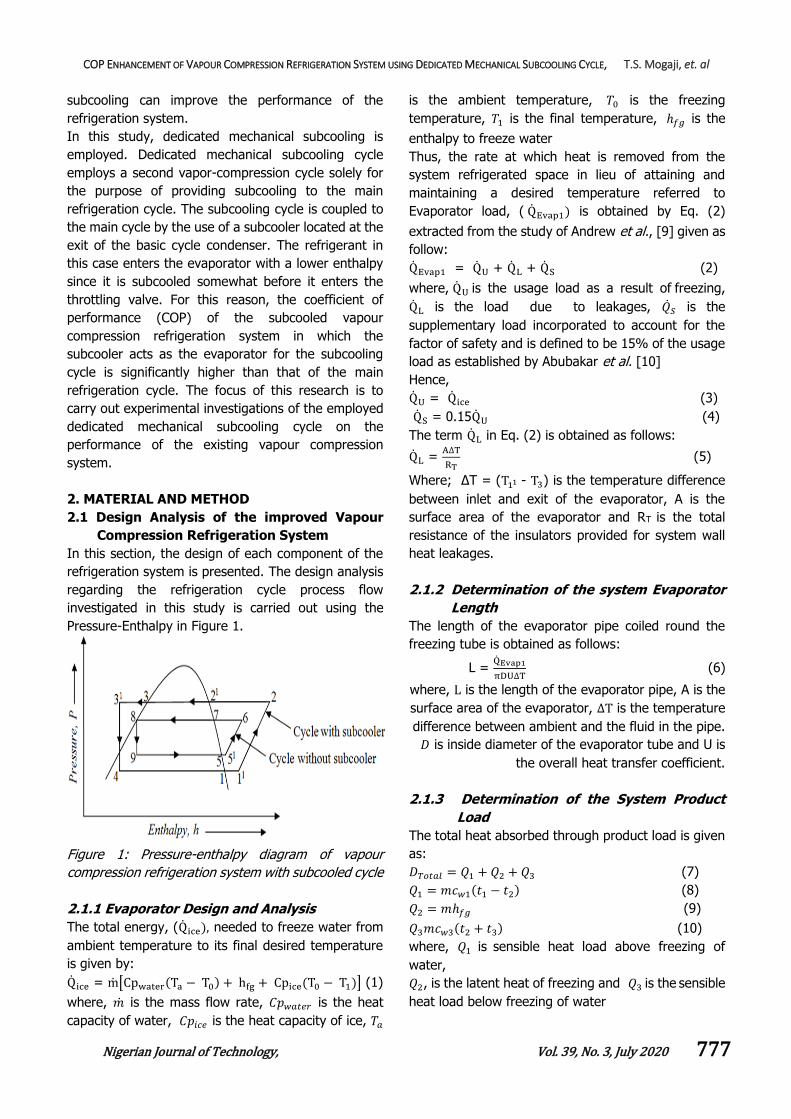
Pressure-Enthalpy in Figure 1.
Figure 1: Pressure-enthalpy diagram of vapour
compression refrigeration system with subcooled cycle
2.1.1 Evaporator Design and Analysis
The total energy, (Qice), needed to freeze water from
ambient temperature to its final desired temperature
is given by:
Qice = m[Cpwater(Ta − T0) + hfg + Cpice(T0 − T1)] (1)
where, �� is the mass flow rate, 𝐶𝑝𝑤𝑎𝑡𝑒𝑟 is the heat
capacity of water, 𝐶𝑝𝑖𝑐𝑒 is the heat capacity of ice, 𝑇𝑎
is the ambient temperature, 𝑇0 is the freezing
temperature, 𝑇1 is the final temperature, ℎ𝑓𝑔 is the
enthalpy to freeze water
Thus, the rate at which heat is removed from the
system refrigerated space in lieu of attaining and
maintaining a desired temperature referred to
Evaporator load, ( QEvap1) is obtained by Eq. (2)
extracted from the study of Andrew et al., [9] given as
follow:
QEvap1 = QU + QL + QS (2)
where, QU is the usage load as a result of freezing,
QL is the load due to leakages, ��𝑆 is the
supplementary load incorporated to account for the
factor of safety and is defined to be 15% of the usage
load as established by Abubakar et al. [10]
Hence,
QU = Qice (3)
QS = 0.15QU (4)
The term QL in Eq. (2) is obtained as follows:
QL = A∆T
RT (5)
Where; ΔT = (T11 - T3) is the temperature difference
between inlet and exit of the evaporator, A is the
surface area of the evaporator and RT is the total
resistance of the insulators provided for system wall
heat leakages.
2.1.2 Determination of the system Evaporator
Length
The length of the evaporator pipe coiled round the
freezing tube is obtained as follows:
L = QEvap1
πDU∆T (6)
where, L is the length of the evaporator pipe, A is the
surface area of the evaporator, ∆T is the temperature
difference between ambient and the fluid in the pipe.
𝐷 is inside diameter of the evaporator tube and U is
the overall heat transfer coefficient.
2.1.3 Determination of the System Product
Load
The total heat absorbed through product load is given
as:
𝐷𝑇𝑜𝑡𝑎𝑙 = 𝑄1 + 𝑄2 + 𝑄3 (7)
𝑄1 = 𝑚𝑐𝑤1(𝑡1 − 𝑡2) (8)
𝑄2 = 𝑚ℎ𝑓𝑔 (9)
𝑄3𝑚𝑐𝑤3(𝑡2 + 𝑡3) (10)
where, 𝑄1 is sensible heat load above freezing of
water,
𝑄2, is the latent heat of freezing and 𝑄3 is the sensible
heat load below freezing of water
COP ENHANCEMENT OF VAPOUR COMPRESSION REFRIGERATION SYSTEM USING DEDICATED MECHANICAL SUBCOOLING CYCLE, T.S. Mogaji, et. al
Nigerian Journal of Technology, Vol. 39, No. 3, July 2020 778
𝑐𝑤1, 𝑐𝑤3 and ℎ𝑓𝑔 are obtained as 3.94 kJ/kgk, 2.01
kJ/kgk and 310.24 kJ/kgk respectively.
2.1.4 Determination of the cooling system
Compressor Power
The compressor power required by the sub-cooling
system is estimated using Eq. (11) as follows:
Psub = msub(h2 − h11) (11)
Where msub, is the mass flow rate of the refrigerant in
the main cycle compressor and subscripts 2 and 11
depicted in Figure 1 refer to the enthalpies of the
refrigerant at the discharge and suction of the
compressor
2.1.5 Selection of the system Condenser
In this work, the condensers were designed using
logarithmic mean temperature difference (LMTD). The
quantity of heat to be removed by the condenser
during the condensation process is expressed
mathematically as:
Qcond1 = msub(h2 − h31) (12)
For the air-cooled condenser, the quantity of heat
given out is expressed as:
Q= AU∆Tlm (13)
∆Tlm = ∆T1 − ∆T2
ln (∆T1
∆T2⁄ )
(14)
where, A is the surface area of the condenser, U is the
overall heat transfer coefficient of the condenser
(W/m2K), ∆Tlm is the logarithmic mean temperature
difference, ∆T1 is the maximum temperature
difference between the cooling fluid and condenser
refrigerant (0C), ∆T2 is the minimum temperature
difference between the cooling fluid and condenser
refrigerant (0C), msub is the mass flow rate of
refrigerant entering the condenser (kg/s), h2 is the
enthalpy of compressed vapour entering the
condenser (kg/kJ), h31 is the enthalpy of liquid leaving
the condenser (kg/kJ).
2.1.6 Main Cycle System Condenser design
The rate of heat transfer between the refrigerant
flowing through the main cycle is equal to the total
heat coming from the subcooled condenser.
Therefore, the total heat absorbed by the main cycle,
Qmain, is given in Eq. (15) as:
Qmain = Qcond1 (15)
While the heat transfer rate from the sub-cooler cycle
condenser is given by:
Qcond1 = mmain(h51 - h9) (16)
Where mmain is the mass flow rate of refrigerant
entering the subcooler (kg/s).
It is interesting to highlight that, in this work, gross
heat rejection, ambient temperature and condensing
temperature as detailed above were carefully
considered in designing the condensers. Thus, the
commonly used type air-cooled condenser is selected
in this study.
2.1.7 Main Cycle Compressor design
With reference to Figure 1, the compressor size of the
subcooling cycle is obtained using Eq. (17) as follows:
W𝑚𝑎𝑖𝑛 = ��𝑚𝑎𝑖𝑛(ℎ6 − ℎ51) (17)
Where;
ℎ51 is the enthalpy of refrigerant at compressor
suction,
h6 is the enthalpy of refrigerant at compressor
discharge.
2.1.8 Determination of the improved Vapour
Compression Refrigeration System (IVCR
system) Coefficient of Performance
The coefficient of performance (COP) of the improved
Vapour Compression Refrigeration System is obtained
as follows:
The COP of the main cycle of the cooling system
defined as the COP at the same evaporator and
condenser temperatures of the system is estimated
using Eq. (18).
𝐶𝑂𝑃𝑚𝑎𝑖𝑛 =𝑅𝑒𝑓𝑟𝑖𝑔𝑒𝑟𝑎𝑡𝑖𝑛𝑔 𝑒𝑓𝑓𝑒𝑐𝑡
𝑤𝑜𝑟𝑘 𝑑𝑜𝑛𝑒 𝑏𝑦 𝑐𝑜𝑚𝑝𝑟𝑒𝑠𝑠𝑜𝑟 (18)
The coefficient of performance of the improved Vapour
Compression Refrigeration System is calculated as:
sub
Csubsub
P
QCOP (19)
Where, CsubQ and
subP are obtained using Eqns. (11)
and (12) respectively.
Thus, performance improvement of the system 𝐶𝑂𝑃𝑖𝑚𝑝
is obtained using Eq. 20 as proposed by Xiaohui et al,
[1] given by:
𝐶𝑂𝑃𝑖𝑚𝑝 = 𝐶𝑂𝑃𝑠𝑢𝑏 − 𝐶𝑂𝑃𝑚𝑎𝑖𝑛
𝐶𝑂𝑃𝑚𝑎𝑖𝑛
× 100% (20)
2.1.9 Materials selection for construction of the
designed IVCR system
The selection of materials was based on its properties,
availability, economic implication and ease of
fabrication. Presented in Table 1 are the materials
selected for development of a freezer-type subcooled
vapour compression refrigeration system in this study.
COP ENHANCEMENT OF VAPOUR COMPRESSION REFRIGERATION SYSTEM USING DEDICATED MECHANICAL SUBCOOLING CYCLE, T.S. Mogaji, et. al
Nigerian Journal of Technology, Vol. 39, No. 3, July 2020 779
Table 1: Material selection
Parts Materials Reasons for selection
Support frame Mild steel High tensile strength, availability
Lagging material
Polystyrene Lightness, low thermal conductivity and durability
Refrigerant R134a Eco-friendly, availability, high COP, good compressor size requirement, non-flammability
Evaporator Copper tube Cost effectiveness, workability, high thermal conductivity, resistance to corrosion
Freezing chamber
Galvanized steel
Weldability and high thermal conductivity
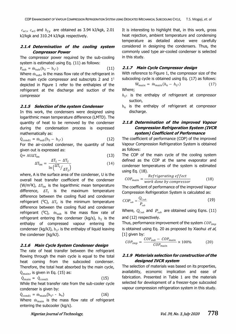
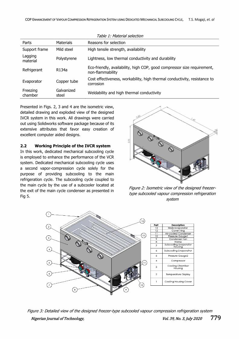
Presented in Figs. 2, 3 and 4 are the isometric view,
detailed drawing and exploded view of the designed
IVCR system in this work. All drawings were carried
out using Solidworks software package because of its
extensive attributes that favor easy creation of
excellent computer aided designs.
2.2 Working Principle of the IVCR system
In this work, dedicated mechanical subcooling cycle
is employed to enhance the performance of the VCR
system. Dedicated mechanical subcooling cycle uses
a second vapor-compression cycle solely for the
purpose of providing subcooling to the main
refrigeration cycle. The subcooling cycle coupled to
the main cycle by the use of a subcooler located at
the exit of the main cycle condenser as presented in
Fig 5.
Figure 2: Isometric view of the designed freezer-
type subcooled vapour compression refrigeration
system
Figure 3: Detailed view of the designed freezer-type subcooled vapour compression refrigeration system
COP ENHANCEMENT OF VAPOUR COMPRESSION REFRIGERATION SYSTEM USING DEDICATED MECHANICAL SUBCOOLING CYCLE, T.S. Mogaji, et. al
Nigerian Journal of Technology, Vol. 39, No. 3, July 2020 780
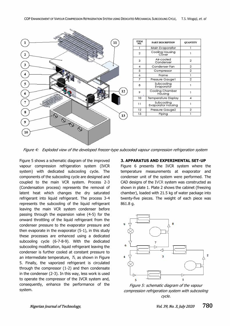
Figure 4: Exploded view of the developed freezer-type subcooled vapour compression refrigeration system
Figure 5 shows a schematic diagram of the improved
vapour compression refrigeration system (IVCR
system) with dedicated subcooling cycle. The
components of the subcooling cycle are designed and
coupled to the main VCR system. Process 2-3
(Condensation process) represents the removal of
latent heat which changes the dry saturated
refrigerant into liquid refrigerant. The process 3-4
represents the subcooling of the liquid refrigerant
leaving the main VCR system condenser before
passing through the expansion valve (4-5) for the
onward throttling of the liquid refrigerant from the
condenser pressure to the evaporator pressure and
then evaporate in the evaporator (5-1), in this study
these processes are enhanced using a dedicated
subcooling cycle (6-7-8-9). With the dedicated
subcooling modification, liquid refrigerant leaving the
condenser is further cooled at constant pressure to
an intermediate temperature, T4, as shown in Figure
5. Finally, the vaporized refrigerant is circulated
through the compressor (1-2) and then condensate
in the condenser (2-3). In this way, less work is used
to operate the compressor of the IVCR system and,
consequently, enhance the performance of the
system.
3. APPARATUS AND EXPERIMENTAL SET-UP
Figure 6 presents the IVCR system where the
temperature measurements at evaporator and
condenser unit of the system were performed. The
CAD designs of the IVCR system was constructed as
shown in plate 1. Plate 2 shows the cabinet (freezing
chamber), loaded with 21.5 kg of water package into
twenty-five pieces. The weight of each piece was
861.8 g.
Figure 5: schematic diagram of the vapour
compression refrigeration system with subcooling
cycle.
COP ENHANCEMENT OF VAPOUR COMPRESSION REFRIGERATION SYSTEM USING DEDICATED MECHANICAL SUBCOOLING CYCLE, T.S. Mogaji, et. al
Nigerian Journal of Technology, Vol. 39, No. 3, July 2020 781
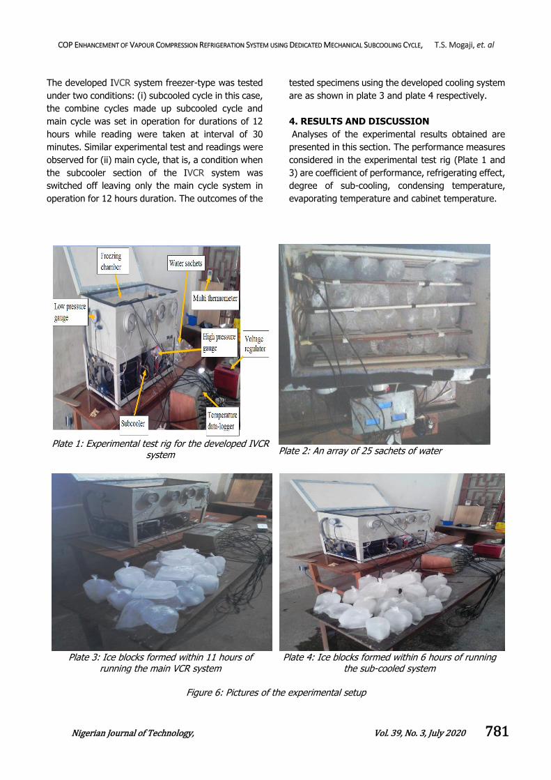
The developed IVCR system freezer-type was tested
under two conditions: (i) subcooled cycle in this case,
the combine cycles made up subcooled cycle and
main cycle was set in operation for durations of 12
hours while reading were taken at interval of 30
minutes. Similar experimental test and readings were
observed for (ii) main cycle, that is, a condition when
the subcooler section of the IVCR system was
switched off leaving only the main cycle system in
operation for 12 hours duration. The outcomes of the
tested specimens using the developed cooling system
are as shown in plate 3 and plate 4 respectively.
4. RESULTS AND DISCUSSION
Analyses of the experimental results obtained are
presented in this section. The performance measures
considered in the experimental test rig (Plate 1 and
3) are coefficient of performance, refrigerating effect,
degree of sub-cooling, condensing temperature,
evaporating temperature and cabinet temperature.
Plate 1: Experimental test rig for the developed IVCR system
Plate 2: An array of 25 sachets of water
Plate 3: Ice blocks formed within 11 hours of running the main VCR system
Plate 4: Ice blocks formed within 6 hours of running the sub-cooled system
Figure 6: Pictures of the experimental setup
COP ENHANCEMENT OF VAPOUR COMPRESSION REFRIGERATION SYSTEM USING DEDICATED MECHANICAL SUBCOOLING CYCLE, T.S. Mogaji, et. al
Nigerian Journal of Technology, Vol. 39, No. 3, July 2020 782
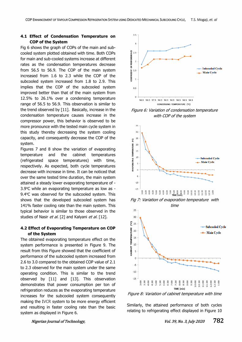
4.1 Effect of Condensation Temperature on
COP of the System
Fig 6 shows the graph of COPs of the main and sub-
cooled system plotted obtained with time. Both COPs
for main and sub-cooled systems increase at different
rates as the condensation temperatures decrease
from 56.5 to 56.9. The COP of the main system
increased from 1.6 to 2.3 while the COP of the
subcooled system increased from 1.8 to 2.9. This
implies that the COP of the subcooled system
improved better than that of the main system from
12.5% to 26.1% over a condensing temperature
range of 56.5 to 56.9. This observation is similar to
the trend observed by [11]. Basically, increase in the
condensation temperature causes increase in the
compressor power, this behavior is observed to be
more pronounce with the tested main cycle system in
this study thereby decreasing the system cooling
capacity, and consequently decrease the COP of the
system.
Figures 7 and 8 show the variation of evaporating
temperature and the cabinet temperatures
(refrigerated space temperatures) with time,
respectively. As expected, both cycle temperatures
decrease with increase in time. It can be noticed that
over the same tested time duration, the main system
attained a steady lower evaporating temperature of -
3.9oC while an evaporating temperature as low as -
9.4oC was observed for the subcooled system. This
shows that the developed subcooled system has
141% faster cooling rate than the main system. This
typical behavior is similar to those observed in the
studies of Nasir et al. [2] and Kalyani et al. [12].
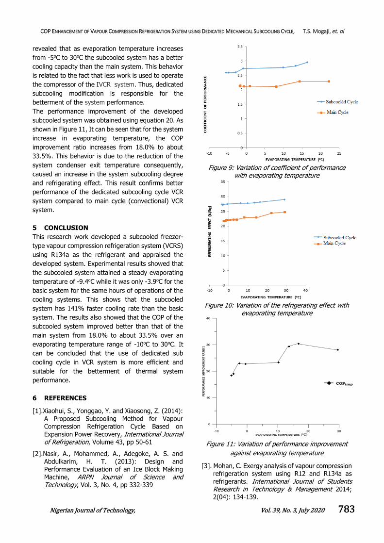
4.2 Effect of Evaporating Temperature on COP
of the System
The obtained evaporating temperature effect on the
system performance is presented in Figure 9. The
result from this Figure showed that the coefficient of
performance of the subcooled system increased from
2.6 to 3.0 compared to the obtained COP value of 2.1
to 2.3 observed for the main system under the same
operating condition. This is similar to the trend
observed by [11] and [13]. This observation
demonstrates that power consumption per ton of
refrigeration reduces as the evaporating temperature
increases for the subcooled system consequently
making the IVCR system to be more energy efficient
and resulting in faster cooling rate than the basic
system as displayed in Figure 6.
Figure 6: Variation of condensation temperature
with COP of the system
Fig 7: Variation of evaporation temperature with
time
Figure 8: Variation of cabinet temperature with time
Similarly, the attained performance of both cycles
relating to refrigerating effect displayed in Figure 10
COP ENHANCEMENT OF VAPOUR COMPRESSION REFRIGERATION SYSTEM USING DEDICATED MECHANICAL SUBCOOLING CYCLE, T.S. Mogaji, et. al
Nigerian Journal of Technology, Vol. 39, No. 3, July 2020 783
revealed that as evaporation temperature increases
from -5oC to 30oC the subcooled system has a better
cooling capacity than the main system. This behavior
is related to the fact that less work is used to operate
the compressor of the IVCR system. Thus, dedicated
subcooling modification is responsible for the
betterment of the system performance.
The performance improvement of the developed
subcooled system was obtained using equation 20. As
shown in Figure 11, It can be seen that for the system
increase in evaporating temperature, the COP
improvement ratio increases from 18.0% to about
33.5%. This behavior is due to the reduction of the
system condenser exit temperature consequently,
caused an increase in the system subcooling degree
and refrigerating effect. This result confirms better
performance of the dedicated subcooling cycle VCR
system compared to main cycle (convectional) VCR
system.
5 CONCLUSION
This research work developed a subcooled freezer-
type vapour compression refrigeration system (VCRS)
using R134a as the refrigerant and appraised the
developed system. Experimental results showed that
the subcooled system attained a steady evaporating
temperature of -9.4oC while it was only -3.9oC for the
basic system for the same hours of operations of the
cooling systems. This shows that the subcooled
system has 141% faster cooling rate than the basic
system. The results also showed that the COP of the
subcooled system improved better than that of the
main system from 18.0% to about 33.5% over an
evaporating temperature range of -10oC to 30oC. It
can be concluded that the use of dedicated sub
cooling cycle in VCR system is more efficient and
suitable for the betterment of thermal system
performance.
6 REFERENCES
[1].Xiaohui, S., Yonggao, Y. and Xiaosong, Z. (2014):
A Proposed Subcooling Method for Vapour Compression Refrigeration Cycle Based on
Expansion Power Recovery, International Journal of Refrigeration, Volume 43, pp 50-61
[2].Nasir, A., Mohammed, A., Adegoke, A. S. and
Abdulkarim, H. T. (2013): Design and Performance Evaluation of an Ice Block Making
Machine, ARPN Journal of Science and Technology, Vol. 3, No. 4, pp 332-339
Figure 9: Variation of coefficient of performance
with evaporating temperature
Figure 10: Variation of the refrigerating effect with
evaporating temperature
Figure 11: Variation of performance improvement
against evaporating temperature
[3]. Mohan, C. Exergy analysis of vapour compression refrigeration system using R12 and R134a as
refrigerants. International Journal of Students Research in Technology & Management 2014;
2(04): 134-139.
COP ENHANCEMENT OF VAPOUR COMPRESSION REFRIGERATION SYSTEM USING DEDICATED MECHANICAL SUBCOOLING CYCLE, T.S. Mogaji, et. al
Nigerian Journal of Technology, Vol. 39, No. 3, July 2020 784
[4]. Oyesola, B. (2017): Hits Millions Making Ice
Block in Recession, reported in The Sun, 27th March, www.sunnewsonline.com
[5]. Bolaji, B.O., Akintunde, M.A., and Falade, T.O.
(2010): Theoretical Investigation of the Performance of Some Environmental-friendly
Refrigerants in Subcooling Heat Exchanger Refrigerator, Journal of Science and Technology,
Volume 30, No 3, pp 101-108
[6]. Bolaji, B.O. (2014): Influence of Subcooling on the Energy Performance of Two Eco-friendly R22
Alternative Refrigerants, Journal of Science and Technology, Volume 34, No 2, pp 73- 83
[7]. Qureshi, B. A. and Zubair, S. M. (2012): The Effect of Refrigerant Combinations on
Performance of a Vapour Compression System
with Dedicated Mechanical Subcooling, International Journal of Refrigeration, Volume
35, pp 47 – 57
[8]. Adegoke, C.O., Akintunde, M.A., and Fapetu,
O.P. (2007): Comparative Exergetic Analysis of
Vapour Compression Refrigeration Systems in the Superheated and Supercooled Regions, All Journals of Technology, Volume 10, No 4, pp 254 – 263
[9]. Andrew, E. E., Abubakar, M., Akinola, A. A. and
Abdulkadir, B. H. (2012): Development and
Evaluation of a Prototype Refrigerated Cooling
Table for Conference Services, International Journal of Engineering and Technology, Volume
4, No 2, pp 97-108
[10]. Abubakar, M., Andrew, E. E., Abdulkadir, B. H. and Akinola, A. A. (2012): The Design of a
cooling table for conference services, Elixir International Journal, Mechanical Engineering, Volume 44, pp 7354-7358
[11]. Mogaji, T. S. and Yinusa, R. K. (2015): Performance Evaluation of Vapour Compression
Refrigeration System Using Double Effect Condensing Unit (Sub-cooler), International Journal of Engineering & Technology Sciences, Volume 03, Issue 01, pp 55-64
[12]. Kalyani, R.K, Naga, S.S. and Rajagopal, K.
(2012): Development of a Chest Freezer –Optimum Design of an Evaporator Coil,
International Journal of Automotive and Mechanical Engineering (IJAME), Volume 5, pp.
597-611
[13]. Ashish, K. P. and Gupta, R. C. (2013): Effect of Sub Cooling and Superheating on Vapour
Compression Refrigeration Systems Using R-22 Alternative Refrigerants; International Journal of Emerging Trends in Engineering and Development, Vol.1, Issue 3, pp 521-531