Embed Size (px)
Citation preview

Coordinating Standards for Cool Roof Testing and Performance
APEC Energy Working GroupSeptember 2020

2
APEC Project: EWG 14 2018A Produced by Sven Mumme / Kurt Shickman and Bipin Shah US Department of Energy Forrestal Building, 1000 Independence Ave, SW Washington, DC 20585, USA For Asia-Pacific Economic Cooperation Secretariat 35 Heng Mui Keng Terrace Singapore 119616 Tel: (65) 68919 600 Fax: (65) 68919 690 Email: [email protected] Website: www.apec.org © 2020 APEC Secretariat APEC#220-RE-01.10

3
Contents Introduction ............................................................................................................................... 4
How Cool Surfaces Work ........................................................................................................... 4
Benefits of Increased Deployment of Cool Surfaces ................................................................. 5
Energy .................................................................................................................................... 5
Climate and Global Cooling .................................................................................................... 6
Air Quality .............................................................................................................................. 6
Human Health ........................................................................................................................ 7
Surface durability ................................................................................................................... 7
Economics and Productivity ................................................................................................... 8
Effects on Social Equity .......................................................................................................... 8
Cool Roof Testing Standards ...................................................................................................... 9
Establishing Cool Surface Testing Infrastructure ..................................................................... 13
Responsibilities of the Certification Governing Body .......................................................... 15
Selecting Cool Roof Product Attributes for Performance Testing and Certification ........... 15
Establishing Minimum Performance Testing and Certification Criteria .............................. 16
The Role of Testing Laboratories and Test Farms ................................................................ 17
Requirements for All Accredited Testing Laboratories.................................................... 17
Ensuring that cool surface products are produced with consistent quality and meet the
certified performance requirements ................................................................................... 19
Quality Control ................................................................................................................. 19
Random Testing of Rated Products ................................................................................. 19
Create a process to label products for the marketplace ..................................................... 19
Cool Roof Product Label Characteristics .......................................................................... 20
Technical Annex 1 .................................................................................................................... 21
Measurements of Solar Reflectance and Emittance to calculate Solar Heat Gain ............. 21
Detail on Solar Reflectance (SR) and Related Optical Properties of Surfaces ..................... 21
Net Solar Heat Gained by a Material Receiving Solar Radiation ......................................... 22
Air Mass and Optical Processes in the Atmosphere ............................................................ 22
Technical Annex 2 .................................................................................................................... 23
Testing Equipment Used for Measurement of Solar Reflectance ....................................... 24
Measurement of Emittance ........................................................................................... 29
References ............................................................................................................................... 33

4
Introduction The use of highly solar reflective, “cool” surfaces (e.g., roofs and walls) has become
increasingly common as a means to increase energy efficiency in buildings with air
conditioning and to improve thermal comfort in buildings lacking air conditioning. This
report, commissioned by the Asia-Pacific Economic Cooperation (APEC), under its Energy
Working Group, reviews the characteristics of highly solar reflective, “cool” surfaces, with a
focus on the standards currently in place in APEC economies for testing material surface
properties. These standards are critical to establishing and enforcing quality products and
effective building codes to promote the use of cool surfaces. Differences in standards
between APEC economies can add confusion and costs for manufacturers seeking to import
and to the end users they are supplying and may contribute to reduced demand or product
availability throughout APEC. By gathering and comparing existing standards, this report
seeks to provide additional clarity to policymakers and industry, highlight areas of
commonality and differences between standards relevant to that audience, offer
recommendations to economies who have not yet adopted cool surface testing standards,
and inform any future discussions on harmonization of standards.
How Cool Surfaces Work The concept of creating cooler structures using a surface’s ability to reflect sunlight and to
efficiently emit absorbed heat dates back to ancient construction. Every opaque urban
surface (e.g. roofs, walls, pavements) reflects some incoming sunlight and absorbs the rest.
Solar radiation absorbed by the exterior surfaces of buildings warms those surfaces. Some of
the heat conducts into the building and some raises the outside air temperature. Reflecting
solar radiation into the sky, ideally through the atmosphere and into space, can reduce the
amount of solar heat gained by buildings, communities, and cities. The effectiveness of so-
called “cool surfaces” is measured by the fraction of solar radiation they reflect versus the
fraction that they absorb and convert into heat (measured by solar reflectance or SR). SR is
measured on a scale between 0 and 1, where 0 represents a pure black surface that reflects
no solar energy and 1 is a pure white surface that reflects all solar energy. These values may
also be expressed as solar absorptance, which is the inverse of solar reflectivity.
The effectiveness of cool surfaces is also measured by how efficiently and quickly they shed
heat. A surface absorbing solar radiation becomes hotter and releases some heat by
convection, radiation, and conduction (measured by thermal emittance or TE). Like SR,
emittance is measured on a scale from 0 to 1. Non-metallic surfaces are typically
characterized by high emissivity (generally in the range of 0.8 to 0.95) while uncoated
metallic surfaces tend to have lower thermal emittance performance. Thus, an uncoated
metal surface that is as reflective as a non-metallic surface will nonetheless remain warmer
because it emits less thermal radiation and absorbs more un-reflected solar heat. Together,
SR and TE are sometimes referred to as the radiative properties of a surface.
Building codes may also reference another cooling indicator called the Solar Reflectance
Index (SRI). SRI is a combination of a surface’s radiative properties in order to simulate roof
conditions on a clear, sunny, summer day. SRI is typically a calculated number considering

5
Solar Reflectance and Solar Emittance, measured from 0 to 100, though it is possible to see
negative values for extremely hot surfaces or values over 100 for an exceptionally cool
material. The use of SRI as a combined measurement of reflectance and emittance in codes
is becoming less common, since it has been shown that two different products with identical
SRI values can yield significantly different energy savings results depending on what
geographic region they are applied in, and the climatic conditions present in this region.
Figure 1 How cool roofs work
Source: Global Cool Cities Alliance (2012), The Cool Roofs and Pavements Toolkit,
https://www.coolrooftoolkit.org/wp-content/pdfs/CoolRoofToolkit_Full.pdf and Lawrence Berkeley National
Laboratory.
Benefits1 of Increased Deployment of Cool Surfaces Average outdoor air temperatures can be reduced by 0.3°C per 0.10 increase in average
solar reflectivity in a city. Peak outdoor air temperature decreases by up to 0.9°C per each
0.10 increase in solar reflectivity.i Indoor air temperatures can also be lowered by adopting
urban cooling strategies. A pilot outside of Ahmedabad, India found that air temperatures
inside a small low-income house with a solar reflective metal roof were 2.5-3.5°C lower than
an identical home with an uncoated metal roof.ii
The ability of highly solar reflective surfaces to reduce indoor and outdoor air temperatures
generates a broad set of benefits for buildings, cities, and the globe.
Energy
Rising temperatures, and trends of global economic growth, are leading to an increase in the
use of air conditioning. Globally, room air conditioners in service are projected to more than
triple by 2050 and increase five-fold in developing economies.iii This growth in air
conditioning is expected to increase energy demand by as much as 58% over the same
period.iv Solar reflective roofs can reduce cooling energy demand by 10 to 40%. In winter,
1 The net benefits of increased surface solar reflectivity will depend on climate, building location and orientation, altitude, annual heating load, annual cooling load, peak energy demand, electricity tariffs, occupancy patterns, shading, material availability, market efficiency, urban form and other factors.

6
heating penalty may range between 5 and 10% as a function of local climate and building
characteristics.v
During extreme heat events, excess demand for space cooling can overload electricity
supply systems and cause power outages.vi,vii Cooling demand will make up over 20% of
peak load in economies like China and South Korea, around 30% in Mexico and the United
States, and over 40% in Indonesia (Figure 2). Increasing the solar reflectance of urban
surfaces could reduce maximum peak power demand by up to 7%.viii
Figure 2 Expected contribution of cooling on peak energy demand
Source: IEA (2018), The Future of Cooling, IEA, Paris https://www.iea.org/reports/the-future-of-cooling.
Climate and Global Cooling
A large-scale shift toward reflective surfaces could cool the world by 0.01–0.07°C by
reducing the amount of heat that is transmitted from the earth’s surface and trapped in
the atmosphere.ix The use of more reflective surfaces in hot cities around the world
could cancel the warming effect of 44–57 billion metric tons of carbon dioxide already
emitted into the atmospherex—up to 75% above current annual global emissions of
carbon dioxide.2,xi
Air Quality Cool surfaces contribute to improved air quality in two ways. First, any energy efficiency
gains resulting from the deployment of cool surfaces will reduce greenhouse gas emissions
from electric power generation – particularly when electricity is generated by fossil-fuel
based power plants located near urban areas. Second, temperature and ground-level ozone
2 Estimate of 9.5 billion metric tons of carbon emitted (35 billion metric tons of carbon dioxide).

7
formation are positively correlated, meaning that concentrated deployments of cool
surfaces that result in lower air temperatures will also reduce hazardous emissions and
smog. Ground-level ozone and smog is a major air-quality concern that significantly
contributes to respiratory illness in cities. Currently, over 1 million deaths per year are
attributed to extended exposure to ozone pollution, the majority of which occur in India and
China.xii While research generally supports that cooler air temperatures have a net positive
effect on air quality, cooler air temperatures may also cause a slight decrease in air quality
by slowing the vertical movement of air from the hot ground level to cooler layers above the
city (known as vertical mixing)xiii
Human Health In an average year, heat is the world’s deadliest natural disaster and heat-related mortality
is expected to dramatically worsen in the coming decades. The World Health Organization
estimates that annual heat-related deaths will rise from 100,000 in 2030 to 250,000 by 2050
as extreme heat events grow in frequency, duration, and intensity.xiv
Heat stress on humans starts to occur when the human body reaches temperatures above
38°C (or 1°C above its normal temperature of 37°C. Excess heat conditions, along with poor
air quality, also exacerbate a number of common health conditions caused by diseases of
the heart, lungs, kidney and diabetes.xv Indoor air temperatures above 27°C contribute to
increased mental stress and sleeping difficulty.xvi
City-scale implementation of cool surfaces reduces air temperatures and can save lives on
dangerously hot days. One study evaluated the effect of increases in the average solar
reflectance of roofs in Chicago and Boston (hot summer, cold winter climates) and found
that both cities would experience an average air temperature reduction of 1.5°C. The
resulting cooler air temperatures could reduce mortality during dangerous heat events by
8.1% and 9.2% in Boston3 and by 2.5% to 10% in Chicago.xvii Beyond saving lives, cooler
temperatures promote outdoor activity, social interaction, and enhance quality of life,
leading to improved mental health.
Surface durability Roof surfaces that absorb a lot of solar radiation (i.e., hot roofs) widen the roof surface’s
diurnal temperature range—daytime high minus nighttime low—and the resulting stress of
thermal expansion and contraction can reduce material stability. Any resulting fatigues can
cause the roof substrate to crack or tear, producing water leakages and shortening of a
roof’s useful life.
3 The low end of the mortality reduction range assumes a 0.15 SR increase in average roof albedo. The upper end of the range assumes a 0.25 SR increase.

8
Economics and Productivity The negative effects of excess heat have substantial implications for urban economies. A
study of 1,692 cities worldwide finds that the effects of excess urban heat and local climate
change will reduce the annual economic output of the median city by 5.6% by 2100 and by
up to 11% in the worst-affected cities.xviii Other studies examine the negative economic
effects of heat including reduced productivity,xix power outages, and transport disruptions.xx
Financial losses from a 2009 heatwave in southeast Australia were estimated to be US$521
million, largely from disruptions to the power grid and transportation system.xxi
Combinations of urban passive cooling solutions, primarily solar reflective and permeable
surface solutions, generate between $1.50 and $15.20 in net benefits for each $1.00
invested, according to a study covering 1,692 cities worldwide (Figure 3).xxii
Figure 3 Benefit and Cost Effects of Cool and Permeable Surfaces
Source: World Bank Group (2020), “Primer on Cool Cities: Reducing Excessive Urban Heat” based on data from
Estrada et al (2017), “A global economic assessment of city policies to reduce climate change impacts,” Journal
Nature Climate Change, https://www.nature.com/articles/nclimate3301.
Effects on Social Equity Without exception, the negative effects of heat described above are disproportionately
borne by poor and marginalized populations. The effect of rising heat is particularly
dire for the 680 million people living in hot, economically impoverished, urban areas
who lack access to air conditioning and must find other solutions to deliver the thermal
comfort needed to live and thrive.xxiii People living in lower-income and less vegetated
areas have a 5% greater chance to die due to heat than those living in wealthier, shadier
areas.xxiv

9
Cool Roof Testing Standards Policy makers and the public are becoming more aware of the substantial benefits
possible from the implementation of cool surfaces. This has led to an increase in their
use in many APEC economies, with some adopting incentives or requirements to spur
market growth. Standards to test radiative properties are essential to ensure effective
policies and informed purchasing decisions. This section reviews the existing standards
in APEC economies for testing the radiative properties of cool surfaces. Table 1
summarizes the existing standards used to test the solar reflectance of building
envelope products (primarily roofs). Table 2 summarizes the existing standards for
testing thermal emittance. Table 3 reorganizes the standards to show which standards
are active by APEC economy.
Table 1: Testing Standards for Solar Reflectance of Surfaces in APEC Economies
Standard Title Comments
ASTM C1549
Standard Test Method for Determination of Solar
Reflectance Near Ambient Temperature Using a Portable
Solar Reflectometer
Testing method
ASTM C 903
Standard Test Method for Solar Absorptance, Reflectance, and
Transmittance of Materials Using Integrating Spheres
Testing method
ASTM E 1918
Standard Test Method for Measuring Solar Reflectance of
Horizontal and Low-Sloped Surfaces in the Field
Testing method
ASTM C1864
Standard Test Method for Determination of Solar
Reflectance of Directionally Reflective Material Using
Portable Solar Reflectometer
Testing method
ASTM E 1980
Standard Practice for Calculating Solar Reflectance Index of Horizontal and Low-
Sloped Opaque Surfaces
Calculation method based on measured Reflectance and Emittance
ANSI/CRRC S100
Standard Test Methods for Determining Radiative Properties of Materials
Testing requirements and procedure
GB/T 31389
Technical Requirements and Evaluation Methods of Solar
Reflective Materials for Exterior Walls and Roofs
Apendix A and B of the standard mention the method used for measurement of Reflectance, similar to ASTM C
903 and C 1549 respectively
JGJ/T287 Testing Standard for Solar Heat Reflecting Insulation Coatings
for Buildings Testing method

10
JGJ/T 359
Technical Specification for Application of Architectural
Reflective Thermal Insulation Coating
Specification standard
JG/T235 Architectural Reflective
Thermal Insulation Coating Specification standard
JIS K 5602 How to Determine Solar Reflectance of Coating
IS K 5602: measurement method using a spectrophotometer, established 2008-09-20, investigated by Japanese Industrial Standards Committee, published by Japanese Standards
Association
JIS K 5675 High Solar Reflectance Paint for
Roof
JIS K 5675: measurement method using a spectrophotometer, defined by the near-infrared solar
reflectance, established 2011-07-20, investigated by Japanese Industrial Standards Committee, published by Japanese Standards Association. Retention of the near-
infrared solar reflectance 24 months after outdoor exposure is measured in JIS K 5675
JSTM J 6151 Measuring Method for Solar
Reflectance of Flat Roof in the Field
measurement method by pyranometer using white and black standard plates, published 2014-09-16 by Japan
Testing Center for Construction Materials
JIS R 3106
Testing Method On Transmittance, Reflectance and
Emittance of Flat Glasses and Evaluation of Solar Heat Gain
Coefficient
Industry in Thailand are using this standard for Reflectance measurement. However, they are planning
to switch to JIS K 5062.
NMX-U-000-SCFI-2015
Building Industry -Buildings-Roof Surfaces with High Solar
Reflectance Index-Specifications and Test
methods
Mexico Test and Specification Industry standard.
QCVN 09:2017/BXD
National Technical Regulation on Energy Efficiency Buildings
Viet Nam building standard -Specifies OTTVm and OTTVT
= Overall Thermal Transfer Value for Roof and Exterior walls. This considers the Solar Gain which requires the
measurement of Reflectance and Emittance
ISO 6946
Building Components and Building Elements — Thermal
Resistance and Thermal Transmittance — Calculation
Methods
Used by Viet Nam in conjunction with TCVN 4605 and TCVN 9258.
TCVN 4605 Heating Techniques - Insulating Components - Design Standard
TCVN 9258 Heat Protection for Residential
Buildings - Design Guide

11
Table 2: Thermal Emittance Test Standards in APEC Economies
Standard Title Comments
ASTM C1371 Standard Test Method for Determination of
Emittance of Materials Near Room Temperature Using Portable Emissometers
Testing method
ASTM C 903
Standard Test Method for Solar Absorptance, Reflectance, and
Transmittance of Materials Using Integrating Spheres
Testing method
ANSI/CRRC S100
Standard Test Methods for Determining Radiative Properties of Materials
Testing requirements and procedure
GB/T 31389 Technical Requirements and Evaluation
Methods of Solar Reflective Materials for Exterior Walls and Roofs
Appendix A and B of the standard mention the method used for measurement of
Reflectance, similar to ASTM C 903 and C 1549 respectively
JIS R 3107 Calculation of Thermal Transmittance of
Glazing
established 1998-03-20, revised 2019-03-20, investigated by Japanese Industrial Standards
Committee, Standards Board for ISO area, Technical Committee on Architecture,
published by Japanese Standards Association. Currently used for opaque material also in
Laboratory
JIS R 3106
Testing Method on Transmittance, Reflectance and Emittance of Flat Glasses
and Evaluation of Solar Heat Gain Coefficient
Industry in Thailand are using this standard for Reflectance measurement. However, they
are planning to switch to JIS K 5062.
NMX-U-000-SCFI-2015
Building Industry -Buildings-Roof Surfaces with High Solar Reflectance Index-Specifications and Test methods
Mexico Test and Specification Industry standard.
QCVN 09:2017/BXD
National Technical Regulation on Energy Efficiency Buildings
Viet Nam building standard -Specifies OTTVm and OTTVT = Overall Thermal Transfer Value
for Roof and Exterior walls. This considers the Solar Gain which requires the measurement
of Reflectance and Emittance
ISO 6946 Building components and building elements
— Thermal resistance and thermal transmittance — Calculation methods
Used by Viet Nam in conjunction with TCVN 4605 and TCVN 9258.
TCVN 4605 Heating Techniques - Insulating Components - Design Standard
TCVN 9258 Heat Protection for Residential Buildings -
Design Guide

12
Table 3: Testing standards for radiative properties by APEC economy
APEC Members Standards Used Comment
Australia ASTM E1549, ASTM E1371, ASTM E1980, ASTM E903, AS/NZ 4859-1
n/a
Brunei Darussalam Currently no standard for Testing Reflectance or Emittance of cool
roof.
Table for Reflectance and Emittance are provided in the economy’s building
code standard
Canada ASTM E1549, ASTM E1371, ASTM
E1980, ASTM E903 n/a
Chile Currently no standard for Testing Reflectance or Emittance of cool
roof. n/a
People's Republic of China
GBT 31389, JGJ287, JGJ359, JGT235-2014
GBT 31389 specifies the testing standard for Reflectance and
Emittance. JGJ and JGT are standards product performance
Hong Kong, China No specific standard for testing
Reflectance or Emittance
Uses OTTV and OTTR in the economy’s building code. The appendix has a table
listing of material Reflectance and Emittance
Indonesia Currently no standard for
Reflectance or Emittance of cool roof.
Table for Reflectance and Emittance are provided in the economy’s Building
Code standard
Japan JIS_K_05602, JIS_K_05675, JSTM-J-7601, JSTM-J-7602, JSTM-J-6151,
JIS-R-3107
JIS R 3107 is standard for measuring Glazing product Emittance and is used
for measuring opaque surface also
Republic of Korea Information not Available
Malaysia Currently no standard for
Reflectance or Emittance of cool roof.
The economy’s code MS1525 requires calculation of RTTV, however does not reference testing procedure. Table for
Reflectance and Emittance are provided in the economy’s building standard
Mexico NMX-U-000-SCFI-2015
Difference from USA methodology is that coatings are tested over standard QUV exposure and at manufacturer’s
recommended thickness. Measure over contrast leneta, in order to asses “extended or solar” contrast
ratio
New Zealand ASTM E1549, ASTM E1371, ASTM E1980, ASTM E903, AS/NZ 4859-1
n/a
Papua New Guinea Currently no standard for
Reflectance or Emittance of cool roof.
n/a
Peru Currently no standard for
Reflectance or Emittance of cool roof.
n/a

13
The Philippines Currently no standard for
Reflectance or Emittance of cool roof.
The economy’s Building Energy code is under public review.
Russia ASTM E903, ASTM E1371, Standards are used for determining
Reflectance and Emittance of Glass but not specifically for cool roofs
Singapore Information not Available There is no known testing standard for
Reflectance and Emittance measurement
Chinese Taipei Same as China n/a
Thailand ASTM E 903-82, JIS R 3106 1998,
ASTM E 1980-01, ASTM C 1371-98, BS EN 12898
Currently the tests for the reflectance of coating have been done in
compliance with JIS R 3106. However, changing to JIS K 5602: 2008 is under
consideration
The United States ANSI-CRRC_S100-2016, ASTM
E1549, ASTM E1371, ASTM E903, E1918, ASTMD751, ASTM C1864
n/a
Viet Nam QCVN 09:2017/BXD
Specifies Reflectance and Emittance requirements for calculating
Resistance. However, there are no Testing standard for Reflectance and
Emittance measurement
Establishing Cool Surface Testing Infrastructure Based on reviewing the good practices established in the U.S. (Cool Roof Rating Council) and
the European Union (European Cool Roofs Council), this section explores the steps
necessary to establishing an effective testing, rating, and labeling program for cool surfaces.
A number of APEC economies do not currently have standards for testing the radiative
properties of materials. These economies may choose to adopt the testing standards
recommended in this document and also a product certification program to manage the
testing, certification, and labeling of roofing products.
Cool surface testing infrastructure refers to an interconnected system of public and private
stakeholders that allow for accurate and reliable materials testing in accordance with local
requirements and standards. These stakeholders include:
Accredited Independent Testing Laboratories (AITLs)– facilities where the surface
(radiative) properties of the materials are tested. In some cases, these labs may also
perform aging and weathering tests. The laboratories are accredited by recognized
accreditation bodies in the economy.
Test Farms – facilities where product samples are installed outside and monitored
over a period of months or years to determine changes in radiative properties
resulting from exposure (i.e., aged ratings).

14
Laboratory Accreditation Bodies – agencies or organizations (typically affiliated with
economy governments) that evaluate lab procedures, staff, and equipment to
ensure proper protocols and standards;
Standards Organizations – economy and international bodies that publish standards
and facilitate the process for establishing and modifying those standards over time.
Code bodies – local, regional, or economy bodies that adopt requirements for
building safety, energy use, and/or sustainability.
Establishing an independent Certification Governing Body (Governing Body) is important to
oversee and manage the testing and certification process, update procedures, validate and
verify the accuracy of results from testing laboratories and weathering facilities, maintain
databases of product testing results, and produce the results and labels for product
packaging. The Governing Body should be made up of a collection of manufacturers,
suppliers, testing laboratories, and advocacy groups including consumer interests,
governmental organizations and educational institutions. The Governing Body should have a
Board of Directors and administrative office to manage the day-to-day operations. The
Board of Directors should be a balanced and representative mix of all types of participants
so every aspect of the industry (e.g., manufacturers, testing laboratories, consumer groups,
research institutions, technical experts, and policy groups) has input.
The Governing Body would hold periodic meetings to discuss issues related to certification
program and create voluntary task groups to work on technical and certification issues on
behalf of the organization. One of the primary roles of the Governing Body is to develop
policies and manage a uniform program for the certification and labeling of cool roof
products, and maintain a database of all certified products for the public to access. The
executive office will comprise of staff members who will be responsible for executing: 1) the
Board of Directors’ policy; 2) financials and accounting; 3) technical and quality control.
Establishing a Governing Body for cool surfaces is the first step that should be taken in a process to develop a viable cool roof testing, and certification program. This Governing Body should be independent (preferably a not-for-profit), and all duties, responsibilities, and elections should be completely voluntary. Figure 4 describes an effective structure for such a governing body.

15
Figure 4: Governance structure for testing organizations
Responsibilities of the Certification Governing Body The Governing Body should undertake several activities to establish an effective testing and
certification regime including:
1. Selecting cool surface product attributes for testing and certification
2. Establishing the minimum performance testing and certification criteria for cool
surfaces;
3. Ensuring that cool surface products are produced with consistent quality and meet
the certified performance requirements;
4. Create a process to label products for the marketplace.
Each of these activities is described in more detail below.
Selecting Cool Roof Product Attributes for Performance Testing and Certification When considering which characteristics and attributes to include in performance testing,
the Governing Body should select those that the cool roof industry is familiar with and for
which there are industry-accepted testing protocols developed and test equipment
available. It will also have to consider which tests to make mandatory for certification and
reporting and which attributes will be considered optional. While the Governing Body will
primarily be interested in establishing a testing and certification program for radiative
properties, attributes and tests may not be limited to energy or thermal performance and
may include:
The water infiltration performance of a cool roof is a measure of the resistance,
under standard condition, a cool roof product can resist before failing.
Scratch resistance of the cool roof surface
Fire resistance of the cool coating and surfaces
Elasticity of the cool roof product membrane to account for seasonal expansion and
contraction due to thermal temperature cycling.
The Governing Body will need to consider a number of program details in consultation with
industry, building science experts, and other stakeholders. These program details include:

16
How long can the test results be used for certification and thus how often does a
manufacturer need to retest and recertify cool roof products?
What physical changes to a cool roof product can be made without triggering the
need for retesting?
How will test results be reported for each attribute including units (e.g., SI or IP), the
number of decimal places reported, and where and what order the attributes are
listed on a label?
Are the attributes and the metrics for those attributes appropriate for all of the use
cases and climatic conditions in the jurisdiction covered by the testing entity?
What exact equipment will be needed by testing labs and is there ae straightforward
and unambiguous process for a testing laboratory to acquire and set up test
apparatus, to calibrate testing equipment and conduct the tests efficiently across a
number of cool roof products (multiple product types in market place, paints,
membranes, shingles, tiles and etc.) from multiple manufacturers.
What is the cost for testing and certification and how does that impact the price of
the end product to the consumer? Could that cost be passed along from all
manufacturers to the consumer? If so, are the costs comparable across all
manufacturers?
Are there international standards, experience and examples that can be drawn upon
for establishing the attributes, and the testing protocols, and is this experience
applicable to the economy?
In 1998, the Cool Roof Rating Council (CRRC) was founded to develop accurate and credible
methods for evaluating and labeling the solar reflectance and thermal emittance (radiative
properties) of roofing products sold in the United States and to disseminate the information
to all interested parties. Many of the required tests by the CRRC rely on standards or
protocols promulgated by the ASTM International (www.astm.org), International Standard
Organization (ISO) and the American National Standards Institute (ANSI) (www.ansi.org) and
are articulated in the ANSI S100 Standard. The actual testing protocol and calibration of the
apparatus is set forth in standards promulgated by the International Organization for
Standardization (www.iso.org), American Nation Standards Institute (http://www.ansi.org)
and the International Electrotechnical Commission (www.iec.ch).
European Cool Roofs Council (ECRC) was also established on similar structure as the CRRC in
the USA and have adopted similar testing and certification standards.
Establishing Minimum Performance Testing and Certification Criteria One of the first actions of the Governing Body is to define the minimum performance rating and certification attributes cool roof products. These attributes and the levels at which they are set according to government requirements (e.g., codes and standards) should ensure that cool roofs provide a high level of cost-effective thermal performance. Beyond establishing the radiative performance of cool surface materials, the testing and certification process should result in:

17
Cool roof products applied to the roof that preserve reflectance and emittance properties of the surface within an acceptable range over the life of the product;
A production process of the Age performance of the cool roof products being certified to follow certain specific quality control and recordkeeping requirements;
The cool roof product meets – at a minimum – thermal (energy) performance characteristics plus other selected attributes (with identified metrics of those attributes) important to the consumer and consumer comfort;
The manufacturing facility being certified to produce cool roof products consistently meeting the certified performance characteristics and maintain quality control.
The Role of Testing Laboratories and Test Farms While the Governing Body establishes the testing program, the actual testing is undertaken
by Accredited Independent Testing Laboratories (AITL) and Approved Test Farms. This
section reviews good practices for setting requirements for AITLs and Test Farms.
An AITL is a testing laboratory that is accredited for compliance with ISO/IEC Standard
17025 to test roofing products and is completely independent from any roofing product
manufacturer or roofing product seller. Accredited shall be defined as achieving third-party
evaluation accreditation by an organization accredited to ISO 17011.
Requirements for All Accredited Testing Laboratories
Testing required by the certification program must be conducted by an AITL. Four good
practices for testing laboratory accreditation include:
The laboratory must submit a completed application to the Governing Body for
consideration as a recognized Accredited Testing Laboratory and pay the required
fees. Laboratory should also meet all ISO/economy accreditation requirement and
provide necessary proof to Governing Body
At least one employee of the Accredited Testing Laboratory must participate in a
laboratory training workshop organized by the Governing Body. All testing for the
purpose of organizational certification shall be performed or supervised by this
person, who shall certify the test results which are reported according to set
requirements.
The laboratory must demonstrate ongoing competency to the certification governing
body by testing reference samples upon request;
Round Robin Testing
As part of ongoing compliance with accreditation, AITLs and Testing Farms shall be provided
with prepared test samples from the Governing Body, without advanced notice, and shall
test and report the findings on those samples to the certification governing body in
accordance to set criteria. The intent of the periodic evaluation is to ensure consistency and
competency of the testing laboratory by evaluating the test results against pre-determined
test results of those same samples. The executive office shall notify the testing laboratory of
the results at the completion of each test, and shall notify the testing laboratory of any
corrective actions that may be necessary.

18
Weathering Tests
A weathering farm should be accredited for compliance with ISO/IEC Standard 17025 to weather and test roofing products, and shall be independent from any roofing product manufacturer or roofing product seller. Accredited Independent Testing Laboratories are also responsible to report testing results of radiative properties after a period of aging and weathering outdoors (often referred to as aged radiative properties). Age testing is done at approved test farm which may be operated by AITL. Such a program helps evaluate the performance of a material under normal usage conditions. AITLs forward product samples for weathering exposure directly to Approved Test Farms after testing for initial radiative properties. After testing samples for aged radiative properties, AITLs are responsible for holding weathered product samples for a period of 90 days or until aged radiative properties are approved by the organization. AITLs must use the most current test method applicable to the roofing product type for measuring the solar reflectance and thermal emittance of aged products.
Specific Requirements for Accredited Independent Testing Laboratories
The Governing Body will have the responsibility of selecting which AITL’s are included in the
program. It is recommended that the governing body require an AITL to demonstrate
certification under either ISO-17025 or ISO25 through submission of the following
information:
Evidence of certification by an accrediting entity listed by the Governing Body as
complying with ISO Guide 58. This list should be published by the organization for
public access.
A listing of test methods that the accrediting entity has found the AITL capable of
performing. The AITL may only use such tests for the purpose of this certification
Program.
An AITL must provide a statement of independence that shows it has no significant
ownership or commercial interest in a supplier or roofing product company and is
not owned by such a company.
Specific Requirements for Test Farms
In order to participate in the testing program established by the Governing Body, a test farm
should meet the following criteria:
A Test Farm should demonstrate certification under ISO 17025.
A Test Farm must have exposure locations as specified by the certification governing
body. Generally, these are chosen to reflect the range of climatic and exposure
conditions that roofing materials would likely be installed in.
A Test Farm should produce a list of exposure methods that an accrediting body has
found the Test Farm capable of performing.
A Test Farm must provide a statement that shows it has no significant ownership or
commercial interest in a supplier or roofing product company and is not owned by
such a company.

19
Ensuring that cool surface products are produced with consistent quality and meet
the certified performance requirements The second key task of the Governing Body will be to ensure that products tested by the
program are of consistent quality to meet the performance requirements. The Governing
Body should work with the AITLs and Test Farms to ensure quality control and undertake
random testing of products already rated by the program,
Quality Control
Cool roof product manufacturer and sellers shall have an appropriate quality control plan in
place that ensures its roofing products maintain the radiative properties at or above the
values they received from the certification program. A manufacturer shall designate at least
one employee as quality control manager at each plant, and shall provide the certification
governing body with the name and contact information of each of these individuals. All
quality control records and the quality control plan shall be made available to the Governing
Body upon written request.
Random Testing of Rated Products
As part of its quality assurance program, the Governing Body should periodically select rated
roofing products, obtain them from the marketplace or from the point of manufacturing,
and have them tested by an AITL. The percentage of products to be tested each year will be
established by the Governing Body. Products are considered to fail periodic testing if the
tested radiative properties from the accredited testing laboratory are more than 0.05 lower
than the certified radiative properties.
Manufacturer shall provide information to the Governing Body regarding where the office
can obtain samples of their product for periodic testing. Each manufacturer shall provide a
list of distributors or contractors, and this information shall be provided with each
application for product rating. The information will be updated annually at the time of
application for product renewal. Parties listed by the manufacturer shall agree to provide
samples to executive office at no cost and upon request by the Governing Body. Requests
for samples shall be made no more frequently than once a year, unless a product fails the
first test and must be retested. Manufacturer shall also agree to have samples collected
from their point of manufacturing in conjunction with their routine quality control
inspections. Roofing product manufacturers shall provide a one-page instruction sheet on
how to collect or prepare the sample. This instruction sheet shall be included with the
application for product rating.
Create a process to label products for the marketplace A third key role for the Governing Body is to create a means for educating the market on the
test results for each product – primarily through the use of a visible label on product
packaging. Beyond informing the marketplace, labeling also facilitates the inclusion of
radiative properties into building codes, voluntary programs, and incentive schemes. Visible
certification showing that a credible laboratory verified the product met established
attributes provides purchasers of cool roof with important assurances about their
investment in energy-efficient products.

20
The label should include the results of all of the tests certified by the Governing Body and be
consumer-friendly, easily identifiable and legible. An example from the U.S. Cool Roof Rating
Council and European Cool Roofs Council are shown in Figure 5.
Figure 5: Examples of Product Labels for Roofing Products
Labels should contain the manufacturer, model number and the results of the tests for the
selected attributes in units familiar to the consumer. The means should be developed to
trace the original certification that indicates the standard which the product was tested, a
name (to provide traceability) the manufacturing facility, the performance level achieved,
the series or model name of the product and other information pertinent to that product.
This label information can be cross-referenced with the certified products database kept by
the Governing Body and a third-party certifying entity.
Cool Roof Product Label Characteristics
Characteristics of the label include:
The official logo of the Governing Body certifying the cool roof product and the web
address of the governing body;
21
Disclaimers about the cool roof label/labeling process from the Governing Body;
Appearance of all the test results of the attributes required by the Governing Body
and – as an option - any test results that are considered optional by the Governing
Body; and
Date the product received the certifications.
The label information should match the data in the certified products database maintained
by the Governing Body. The Governing Body provides the template for the labels to the
manufacturer with guidance on when, where, and how long it is to be affixed. The
Governing Body will formally inform the manufacturer when all tests and certifications have
been received. The manufacturer can create and attach the label at that time.
Technical Annex 1
Measurements of Solar Reflectance and Emittance to calculate Solar Heat Gain
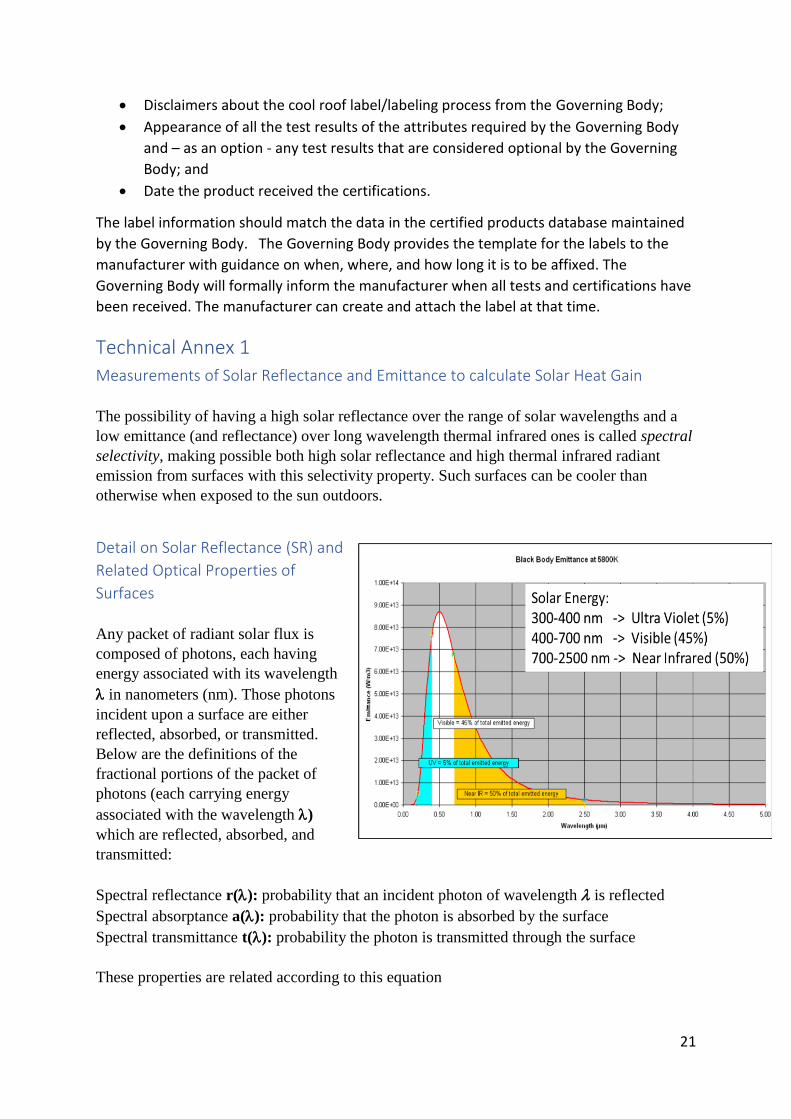
The possibility of having a high solar reflectance over the range of solar wavelengths and a
low emittance (and reflectance) over long wavelength thermal infrared ones is called spectral
selectivity, making possible both high solar reflectance and high thermal infrared radiant
emission from surfaces with this selectivity property. Such surfaces can be cooler than
otherwise when exposed to the sun outdoors.
Detail on Solar Reflectance (SR) and
Related Optical Properties of
Surfaces
Any packet of radiant solar flux is
composed of photons, each having
energy associated with its wavelength
in nanometers (nm). Those photons
incident upon a surface are either
reflected, absorbed, or transmitted.
Below are the definitions of the
fractional portions of the packet of
photons (each carrying energy
associated with the wavelength )
which are reflected, absorbed, and
transmitted:
Spectral reflectance r(): probability that an incident photon of wavelength is reflected
Spectral absorptance a(): probability that the photon is absorbed by the surface
Spectral transmittance t(): probability the photon is transmitted through the surface
These properties are related according to this equation

22
r() + a() + t() = 1 (1)
For opaque surfaces t() = 0 and the solar spectral absorptance for opaque surfaces is
a()=1- r() (2)
Kirchhoff’s law states that for most ordinary materials, the absorptance equals the emittance,
a() = ε(). This is generally true for specific wavelength ranges, in which case the total
values over such a specific wavelength range for each would obey a = ε.
Net Solar Heat Gained by a Material Receiving Solar Radiation
The net solar radiant heat gained (absorbed) by a material is the quantity of solar flux in
Watts that is retained by that material due to absorption, after the portion of that gain which is
re-emitted back into the air through which the solar radiation travelled is subtracted.
When we think of solar radiation incident upon a wall or roof, we usually speak of the
irradiance of the incident radiation, point for point across that surface. Irradiance is the flux
per unit area in W/m2 propagating from the sun onto the surface. The portion of the incident
solar irradiance admitted as solar heat gain per unit area we call Ead, in W/m2. This is the
incident solar irradiance Es multiplied by the solar absorptance am of the material, following
the notation of equations (1) and (2), integrated over the relevant wavelength range:
Ead = am ∙ Es (3)
The main process causing some of this admitted solar heat to be lost back out is the radiant
emission as irradiance Eradiated due to the increased temperature of the surface (from T1 to
T2) produced by the solar heat gained, given by
Eradiated = εσ(T24 – T1
4) (4)
Where ε is the emittance (or emissivity) of the surface, σ is the Stefan-Boltzmann Constant
(5.67 x 10⁻⁸ Watt per square meter and per degree Kelvin to the 4th power or W · m -2 · K -4), and T is the
absolute temperature of the surface in degrees Kelvin.
The final net solar heat gained, therefore, is given by
ESHG = Ead – Eradiated = Es ∙ am – ε σ (T24 – T1
4) (5)
Air Mass and Optical Processes in the Atmosphere
Due to the large distance between the sun and the earth, a beam of solar radiation reaching
the top of the atmosphere is almost parallel. (Solar disk angular diameter is 0.533 degree,

23
31’27” of arc, & 6.807×10⁻⁵ sr of solid angle, so the angular divergence or spread of rays
approaching the atmosphere from the sun has these relatively small values.)
When the sun is directly overhead (at the zenith in the sky) the atmospheric depth (thickness)
is at a minimum for that condition (occurs only at lower latitudes, below about 23 degrees).
The atmosphere is defined to have what is called a Relative Air Mass of 1.0 for the zenith
position in the sky (straight up). As the sun moves down towards the horizon, the air mass
increases to approximately 38 at the horizon. Air mass can be less than one at an elevation
greater than sea level. The effects of absorption and scattering are correspondingly greater
for large air mass values and the spectral distributions of both solar flux and diffuse sky
radiation are altered.
The wavelengths of terrestrial (close to the Earth) solar radiation range from high photon
energy ultraviolet (UV) radiation through the ‘visible’ (VIS) part of the spectrum (~360 nm
to ~830 nm), to the lower photon energy ‘near’ infrared (NIR) region. The maximum
intensities are found in the visible part of the spectrum, with wavelengths between 400 and
700 nm. The intensities in the UV and NIR regions of the spectrum are much lower. Being
very hot, the sun emits no‘far’ infrared radiation (FIR). The much cooler Earth does emit
both IR and FIR radiation, especially when heated by solar radiation. The Earth’s emitted IR
radiation is partially absorbed and re-radiated by gases, particles and clouds in the
atmosphere. Daytime-absorbed solar heat radiates at night into deep space, less so when the
night sky is cloudy and humid, so absorbs some of the Earth’s radiated heat. (Mornings after
a clear night sky tend to have cooler air temperatures because night radiation from the earth
into the sky is less absorbed in the drier atmosphere during clear sky conditions.)
When passing through the atmosphere, some incident solar radiation reaches the Earth’s
surface mostly undisturbed and some is scattered or absorbed by air molecules, aerosol
particles, water droplets and/or ice crystals in clouds and aircraft contrails. Gaseous
molecules and aerosols cause most of the absorption. Scattering of solar radiation by larger
particles like water droplets and ice crystals takes place over the whole spectral range, and is
much less wavelength-selective (making clouds white), whereas the much smaller molecules
predominantly scatter solar radiation greater at short wavelengths (blue part of visible
spectrum) and at larger angles of scattering (making the clear sky blue).. Large aerosol
particles including water droplets mainly scatter at lesser angles of scattering.
Multiple repeated scatterings of light produce a wider angular spreading of the scattered light.
These processes significantly affect the spectrum of radiation that reaches the Earth’s surface.
The stronger scattering of short wavelength (blue) sky light is responsible for the blue color
of clear-sky daylight. Sunset light is more reddish in color, due to the blue having been
removed by the greater distance sunlight travels when low in the sky and that longer
wavelengths in the red end of the spectrum remain strong when the sun nears the horizon,
making the rising and setting sun orange to red in color.
Technical Annex 2
24
Testing Equipment Used for Measurement of Solar Reflectance
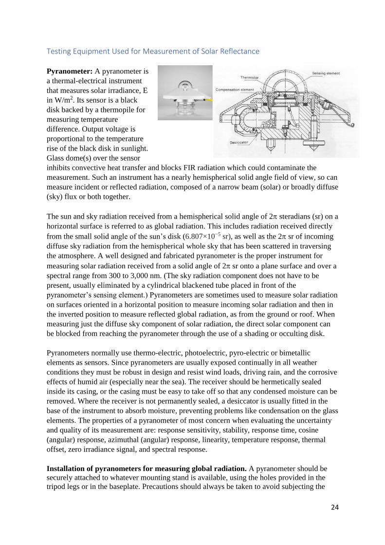
Pyranometer: A pyranometer is
a thermal-electrical instrument
that measures solar irradiance, E
in W/m2. Its sensor is a black
disk backed by a thermopile for
measuring temperature
difference. Output voltage is
proportional to the temperature
rise of the black disk in sunlight.
Glass dome(s) over the sensor
inhibits convective heat transfer and blocks FIR radiation which could contaminate the
measurement. Such an instrument has a nearly hemispherical solid angle field of view, so can
measure incident or reflected radiation, composed of a narrow beam (solar) or broadly diffuse
(sky) flux or both together.
The sun and sky radiation received from a hemispherical solid angle of 2 steradians (sr) on a
horizontal surface is referred to as global radiation. This includes radiation received directly
from the small solid angle of the sun’s disk (6.807×10⁻⁵ sr), as well as the 2 sr of incoming
diffuse sky radiation from the hemispherical whole sky that has been scattered in traversing
the atmosphere. A well designed and fabricated pyranometer is the proper instrument for
measuring solar radiation received from a solid angle of 2 sr onto a plane surface and over a
spectral range from 300 to 3,000 nm. (The sky radiation component does not have to be
present, usually eliminated by a cylindrical blackened tube placed in front of the
pyranometer’s sensing element.) Pyranometers are sometimes used to measure solar radiation
on surfaces oriented in a horizontal position to measure incoming solar radiation and then in
the inverted position to measure reflected global radiation, as from the ground or roof. When
measuring just the diffuse sky component of solar radiation, the direct solar component can
be blocked from reaching the pyranometer through the use of a shading or occulting disk.
Pyranometers normally use thermo-electric, photoelectric, pyro-electric or bimetallic
elements as sensors. Since pyranometers are usually exposed continually in all weather
conditions they must be robust in design and resist wind loads, driving rain, and the corrosive
effects of humid air (especially near the sea). The receiver should be hermetically sealed
inside its casing, or the casing must be easy to take off so that any condensed moisture can be
removed. Where the receiver is not permanently sealed, a desiccator is usually fitted in the
base of the instrument to absorb moisture, preventing problems like condensation on the glass
elements. The properties of a pyranometer of most concern when evaluating the uncertainty
and quality of its measurement are: response sensitivity, stability, response time, cosine
(angular) response, azimuthal (angular) response, linearity, temperature response, thermal
offset, zero irradiance signal, and spectral response.
Installation of pyranometers for measuring global radiation. A pyranometer should be
securely attached to whatever mounting stand is available, using the holes provided in the
tripod legs or in the baseplate. Precautions should always be taken to avoid subjecting the

25
instrument to mechanical shocks or vibration during transport and installation. This operation
is best effected as follows. First, the pyranometer should be oriented so that the emerging
leads or the connector are located poleward of the receiving aperture (See ASTM E 1918).
This minimizes heating of the electrical connections by the sun. Instruments with Moll-
Gorcynski thermopiles should be oriented so that the line of thermo-junctions (the long side
of the rectangular thermopile) points east-west. This constraint sometimes conflicts with the
first, depending on the type of instrument, and should have priority since the connector could
be shaded, if necessary.
When towers are nearby, the instrument should be situated on the side of the tower towards
the Equator, and as far away from the tower as practical, to prevent shadowing.
Radiation reflected from the ground or the base should not be allowed to irradiate the
instrument body from underneath. A cylindrical shading device can be used, but care should
be taken to ensure that natural ventilation still occurs and is sufficient to maintain the
instrument body at ambient temperature.
The pyranometer should then be secured lightly with screws or bolts and levelled with the aid
of the levelling screws and spirit-level provided. After this, the retaining screws should be
tightened, taking care that the setting is not disturbed so that, when properly exposed, the
receiving surface is horizontal, as indicated by a spirit-level.
The stand or platform should be sufficiently rigid so that the instrument is protected from
severe shocks and the horizontal position of the receiver surface is not changed, especially
during periods of high winds and strong solar energy.
The cable connecting the pyranometer to its recorder should have twin conductors and be
waterproof. The cable should be firmly secured to the mounting stand to minimize rupture or
intermittent disconnection in windy weather. Wherever possible, the cable should be properly
buried and protected underground if the recorder is located at a distance. The use of shielded
cable is recommended with the pyranometer, cable and recorder being connected by a very
low resistance conductor to a common ground. As with other types of thermo-electric
devices, care must be exercised to obtain a permanent
copper-to-copper junction between all connections prior
to soldering. All exposed junctions must be weatherproof
and protected from physical damage. After identification
of the circuit polarity, the other extremity of the cable
may be connected to the data-collection system in
accordance with the relevant instructions.
Spectrophotometer: A spectrophotometer is composed
of a spectrometer to angularly spread a beam of radiation
into its component wavelengths, for separate
measurement, as illustrated to the right and below,
including additional components described further.
Spectrometer: Any instrument which receives a beam of
electromagnetic radiation and “disperses” the radiant flux into a continuum of spectral flux at
different wavelengths, separated spatially for human observation (as in the eyepiece of old

26
glass prism spectrometers or using electrical flux detectors to produce measurement results)
of the strength or magnitude of the flux at different wavelengths over the spectral range of
interest. This spreading of spectral flux produces what is called a “spectrum.” The term is
also applied to the graphical representation of the observations or measurements of the
spectral flux over a wavelength scale presented graphically on paper or electronically on a
computer screen.
Optical Dispersing Devices: Components physically separating the beam of flux into its
frequency or wavelength components and sending them to the detection device(s). The
primary dispersion devices are glass prisms and ruled or holographically created diffraction
gratings.
Examples include a glass prism and a ruled
reflective diffraction grating (or its older
transmissive version), an optical component
with a periodic structure that splits and
diffracts light into several beams travelling in
different directions, each beam called a
diffraction order. The directions of these
beams depend on the spacing of the rulings in
the grating and the wavelength of the light so
that the grating acts as the dispersive element.
Detection Devices: To quantify the relative
amounts of flux at each different wavelength
range selected for measurement, an optical
radiation detector is used. These devices produce an electrical current proportional to the
electromagnetic flux incident upon their front surfaces. A linear array of such detectors is
placed in the output beam from a prism or one of the orders emerging from a grating
dispersion device. The signals from these are sent to multichannel analyzers which convert
the radiant flux on each detector into an electrical current output proportional to the flux
received by the detector and this is measured for each detector covering a small wavelength
range of interest. Alternatively, the spectrum can be physically scanned across a single
detector or the detector moved across the output spectrum sending its signal to the recording
system which outputs and/or stores the resulting absolute flux measurement for documenting
the results numerically.

27
Integrating Sphere; To gather radiation
having angular spread from little to
substantial, the integrating sphere is
commonly used. It is a thin metallic
sphere whose interior surface is having
both a highly diffuse and highly
reflective white material, spreading
reflected radiation over a large angular
range. Many multiple reflections within
the sphere render the interior flux very
travelling in all directions. A small
circular hole is cut into the sphere to
admit the incident beam of flux. At 90ᴼ
to this entrance port a detector is placed to measure the flux scattered from the wall of the
sphere. Alternatively, the detector can be placed outside the sphere but inside a short cylinder
so that it receives diffuse radiation mostly from the opposite wall of the sphere. Another
alternative is to replace the detector with the entrance port of a spectrometer, so as to measure
a large number of wavelengths in the incident beam separately. Such a sphere can also be
used to convert a beam into diffuse radiation having a large angular spread.
Laboratory Grade Spectrophotometers: Complete, commercially available, instruments
capable of relatively automated measurements of glass reflectance over the full solar spectral
range, for glass and other surfaces are available in a variety of packages and capabilities from
several manufacturers. Searches on solar spectral reflectance instruments, should provide
information on the most appropriate laboratory and field-portable instruments for determining
these properties. Scrolling down through these and similar search returns will reveal
information from manufacturers and tutorial information on the topics of the searches.
ASTM E 903 is a standard test method for solar absorptance, reflectance, and transmittance
of materials using integrating sphere spectrophotometers which describes generically the use
of a sophisticated laboratory instrument for measuring the spectral reflectance for direct beam
incidence and hemispherical solid angle collection of reflected flux, on a wavelength-by-
wavelength basis over the relevant solar spectral region of 300 to 2500 nm. Lawrence
Berkeley National Laboratory uses a Perkin-Elmer Lambda 1050 UV-VIS-NIR spectrometer
with a Labsphere integrating sphere attachment to make these spectral reflectance
measurements.
Solar Spectrum Reflectometer (SSR): Rapid, accurate, and repeatable measurements of
solar reflectivity are possible with a less expensive specialty instrument called a Solar
Spectrum Reflectometer (SSR). The unit, consisting of measurement head and associated
electronics, features a direct digital readout of total solar reflectivity with resolution to 0.001
and repeatability of +/- 0.003 reflectivity units.
Drift compensation and automatic zeroing is designed into the device to minimize the
requirements for periodic calibration by the user, thus making the instrument ideal for
quality control and R&D. Other features include the use of a single tungsten-halogen light
source, and a four-detector combination (new version has six-detectors which help the

28
measurement to be more accurate and closer to Spectrophotometer measurements in
accordance with ASTM E903). The SSR provides a measurement spectrum that closely
approximates a standard AM1 solar spectrum. Other terrestrial solar spectra can be set by the
user.
The model SSR-ER version 6 features a selectable solar measurement spectrum matched to a
variety of standard global and beam normal solar irradiance models. The SSR provides
accurate measurements on both diffuse and specular materials, even second surface reflectors
up to 0.25 inches (6.4 mm) thick.
Apparatus
The test method described here applies to the determination of directional hemispherical solar
reflectance using a commercial portable reflectometer. The instrument utilizes the principles
of an integrating sphere for performing optical reflectance measurements in the spectral
region from 335 to 2,500 nm. The instrument consists of two units, the Measurement Head
and the Command Module (Fig. 1).
410-Solar-i Reflectometer by Surface Optics Corporation, left, and Solar Spectrum
Reflectometer Model SSR V6 by Devices and Services Company, right.
Measurement Head. The Measurement Head is constructed around an integrating sphere for
measurements of directional-hemispherical reflectance. Light from a tungsten halogen lamp
enters the integrating sphere through an internal beam port at a 20° angle of incidence and
illuminates the test specimen placed over the sample port of the integrating sphere. The flux
reflected from the sample multiply and diffusely reflects around the interior of the sphere and
becomes uniformly diffused. A portion of that light reaches the detector arrays which are
used to measure the directional-hemispherical in-band reflectance. Optical filters and detector
arrays cover seven spectral bands in the wavelength range of 335 to 2,500 nm (335-380, 400-
540, 480-600, 590-720, 700-1,100, 1,000-1,700, and 1,700-2,500 nm). A rubber ring protects
the measured surface from contact with the metal surface of the integrating sphere and
provides a non-skid surface to press against the sample surface.
Command Module. The Command Module provides:
Computer processing
Electrical power
Structural support for the Measurement Head

29
The housing of the Command Module contains the
Trigger,
Battery Cartridge
a small Personal Digital Assistant (PDA) type computer
Light Emitting Diode (LED) & Vibrator Motor indicators
Secure Digital (SD) card port
Measurement Head mechanical and electrical connections
Input / Output port
safety strap.
The computer is located at the top of the handle with a touch screen display that faces the
user during operation. The user controls the unit by selecting various software functions from
the touch screen interface and pressing the trigger when a measurement is to be made.
Calibration Coupon. Calibration of the reflectometer is accomplished with a manufacturer-
supplied calibration coupon. The reflectance values of the provided coupon are stored on the
supplied SD card. Zero reflectance is measured with no sample present at the sample port of
the integrating sphere. The Measurement Head must be pointed away from artificial light
sources such as fluorescent lighting or into a darkened black box, during the Zero
measurement.
During the calibration process (and during each sample measurement cycle), the instrument
automatically makes an additional measurement of the light beam reflected from a specific
location on the wall of the integrating sphere.
A ratio of the electrical signal generated by the detector when the beam illuminates the
sample to that when the beam illuminates the reference point on the integrating sphere is used
in the calculation of sample reflectance values.
This normalization process eliminates most of any instrument drift that might be caused by
thermal or electrical system instabilities.
Test Specimens. Specimens to be tested can be flat, concave (inner diameter larger than 15
cm), or convex (outer diameter larger than 8 cm), and may have specular or diffuse
characteristics. The sample is illuminated with an elliptical spot of about 12 mm at the major
axis and 6 mm at the minor axis. The sample port of the integrating sphere is pressed flush
against the measured surface, which must have a minimum dimension of 13 mm.
Measurement of Emittance Emittance of a surface is the ratio of the actual radiant emission of thermal radiant flux from
a surface to that emitted by what is called a perfect blackbody emitter, at the same
temperature. Symbol ε. (The term emissivity generally applies to the same property for a
material substance rather than an actual object.) Infrared radiation emitted from warm to
moderately hot materials generally has wavelengths in the infrared region of the
electromagnetic spectrum, those above about 800 nanometers. At any wavelength (or over a

30
defined range of wavelengths), a low emittance surface generally has high reflectance. In
consequence, a low infrared emittance surface can help reduce the fraction of incident solar
heat gained by such a surface, as well as the resulting material stresses and failures and the
rate of interior heating from that surface.
Most conventional roofing materials (excepting bare metals like aluminum or steel) have a
fairly high infrared emittance and consequently low reflectance, producing higher solar heat
gain than one might otherwise like.
Good convective heat transfer away from a surface heated by the sun is also desirable,
helping to carry away the solar heat absorbed by that surface into the outside air. In some
roofing systems air can circulate underneath the outer roofing material (e.g., vented tile and
wood shake systems, or vented corrugated metal roofing). Attic venting also can be used to
carry away heated air before it penetrates into the conditioned space.
Measurements of emittance can be done in several ways. The most direct method involves
forming an object (made of the same material as the sample to be measured) into the shape of
a cavity, in such a way that near-blackbody radiation is emitted inside the cavity. A small
hole in this object is made to allow the interior radiation out. A measurement is then made to
compare the radiation from within the formed cavity to radiation from a flat, outside surface
of the same test material, presumably at the same temperature (Sparrow et al., 1973). The
cavity can be given the form of a cylinder, cone, or sphere.
Care must be taken that the specimen is isothermal (same temperature throughout) and that
the reflected radiation is measured and compared from the two objects. The definitive
measurements of several materials, such as tungsten (DeVos, 1954), were determined in this
fashion. The significant advantage in this direct method is that it is relative, depending on
neither absolute radiometry nor thermometry, but only requiring that the radiometer or
spectroradiometer be linear over the dynamic range of the measurement. This linearity is also
determinable by relative measurements.

31
If a variable-temperature
blackbody simulator and a
suitable thermometer are
available, the specimen can
be heated to the desired
temperature Ts and the
blackbody simulator
temperature Tbb can be
adjusted such that its
(spectral) radiance matches
that of the specimen. Then
the (spectral) emittance is
calculable using the
following equations for
spectral emittance ε(λ) and
emittance ε (for a graybody
only).
𝜀(λ) = (𝑒𝐶2/𝜆∗𝑇𝑠) − 1/
(𝑒𝐶2/𝜆∗𝑇𝑏𝑏) − 1 (6)
𝜀 = 𝑇𝑏𝑏4/𝑇𝑠
4 (7)
If an absolutely calibrated radiometer and a satisfactory thermometer are available, a direct
measurement can be made, as Lb is calculable if the temperature is known. Again, the
reflected radiation must be considered included.
Simple ‘‘inspection meter’’ techniques have been developed, and instrumentation is
commercially available to determine the hemispherical emittance over a limited range of
temperatures surrounding the ambient temperature. These instruments provide a single
number, as they integrate both spatially and spectrally. A description of the technique can be
found in ASTM E408.
Measurements of spectral emittance are most often made using spectral reflectance
techniques, invoking Kirchhoff’s law along with the assumption that the transmittance is
zero. A review of early work is found in Dunn et al (1966a) and Millard and Streed (1969).
The usual geometry of interest is directional-hemispherical. This can be achieved by either
hemispherical irradiation-directional collection or using Helmholtz reciprocity (Clarke and
Perry, 1985), (directional irradiation-hemispherical collection). Any standard reflectometry
technique is satisfactory.
A direct method for the measurement of total (integrated over all wavelengths) hemispherical
emittance can use a calorimeter as shown in Fig. 8. A heated specimen is suspended in the
center of a large, cold, evacuated chamber. The vacuum minimizes gaseous conduction and
convection. If the sample suspension is properly designed, the predominant means of heat
transfer is radiation. The chamber must be large to minimize configuration factor effects
between the chamber and the specimen. The chamber is cooled to Tc to reduce radiation from
Figure 6: Calorimetric measurement of total hemispherical emittance

32
the chamber to the specimen. Being cold minimizes external radiation or conduction
contaminations of the process.
The equation used to determine emittance ε is
𝜀 = 𝑃
𝜎 ∗ 𝐴 ∗ (𝑇𝑠4 − 𝑇𝑐
4) (8)
where P is the power input to the specimen heater necessary to maintain an equilibrium with
specimen temperature Ts and A is the specimen area. The equation has been simplified with
the aid of the following assumptions: (1) no thermal conduction from the specimen to the
chamber, (2) no convective losses, (3) equilibrium has been achieved, and (4) the specimen
area is much less than the chamber area. The power can be supplied electrically by means of
a known heater or optically via a window in the chamber. In the latter case, a direct
measurement of the ratio of solar absorptance αs to thermal emittance εT can be directly
obtained if the optical source simulates solar radiation. By varying the input power, the
emittance can be determined as a function of temperature. There are numerous small
corrections to account for geometry, lead conduction, etc. Details can be found in ASTM
C835, ASTM E434, Edwards (1970), and Richmond and Harrison (1960).
ASTM E1371 is currently used by the industry and building codes in the USA and many
APEC economies as means to measure surface emissivity.
Laboratory Grade FTIR Spectral Emittance Measurement Devices
Searches on spectral emissivity measuring instruments and Instruments for measuring IR
emissivity of surfaces should provide information on the most appropriate laboratory and
field-portable instruments for determining both spectral and broadband properties. Scrolling
down through these and similar search returns will reveal information from manufacturers
and tutorial information on the topics of the searches and manuals describing the correct
operation of the relevant instruments. “FTIR” refers to “Fourier Transform InfraRed”
measurements. Instead of a prism or grating spectrometer, a version of the Michelson
interferometer is used. Source radiation travels through a 45 degree angled beam splitter. One
beam goes to a fixed mirror while the other of equal flux level to a movable mirror. Upon
returning to the beam-splitter, the two beams are combined as they emerge and sent to a
radiation detector. All wavelengths are present. However, each wavelength produces
oscillations between the brightness of constructive interference when that wavelength of the
radiation from both beams is in phase and the darkness of destructive interference when the
movable mirror produces destructive interference (zero flux in the combined beam at that
wavelength emerging from the beam-splitter. This apparently jumbled mess is separated out
by recording the emerging radiant flux as the movable mirror is scanned through a suitable
distance. The emerging flux will be varying differently at each wavelength. By applying a
formula based on the Fourier mathematical transform, the true spectrum can be elucidated.
The first commercially available instrument using this method for infrared measurements was
offered for sale in 1969.

33
References Akbari H., H.D. Matthews and D. Seto (2012), “The long-term effect of increasing the albedo
of urban areas,” Environmental Research Letters 7: 10 pp.
Akbari, H., S. Menon and A. Rosenfeld (2009), “Global cooling: increasing world-wide urban albedos to offset CO2,” Climatic Change 94:275–286. Añel, J., M. Fernández-González, X. Labandeira, X. Lopez-Otero, L. de la Torre Ramos (2017), “Impact of Cold Waves and Heat Waves on the Energy Production Sector” Atmosphere, 8. 209. 10.3390/atmos8110209. Campbell, I., A. Kalanki and S. Sachar (2018), “Solving the Global Cooling Challenge,” http://rmi.org/wp-content/uploads/2018/11/Global_Cooling_Challenge_Report_2018.pdf. Chhetri, P., A. Hashemi, F. Basic, A. Manzoni and G. Jayatilleke (2012), “Bushfire, Heat Wave and Flooding Case Studies from Australia,” Report from the International Panel of the Weather project funded by the European Commission’s 7th framework programme. Melbourne, March 2012. Epstein, S.A., L., Sang-Mi, A.S. Katzenstein, M. Carreras-Sospedra, X. Zhang, S.C. Farina, P.
Vahmani, P.M. Fine and G. Ban-Weiss (2017) “Air-quality Implications of Widespread
Adoption of Cool Roofs on Ozone and Particulate Matter in Southern California,”
Proceedings of the National Academy of Sciences USA 114(34) 8991-8996 doi
10.1073/pnas.1703560114
Estrada, F., W. Botzen and R. Tol (2017), “A global economic assessment of city policies to reduce climate change impacts,” Journal Nature Climate Change, DOI: 10.1038/NCLIMATE3301. Kalkstein, L., F. Klink, K. Shickman, S. Schneider, M. Egolf and D. Sailor (2020) “The Potential
Impact of Cool Roof Technologies Upon Heat Wave Meteorology and Human Health in
Boston and Chicago,” Roofing Research and Standards Development: 9th Volume, ASTM
International, https://doi.org/10.1520/STP1621-EB
Le Quere C. et al. (2013), “The global carbon budget 1959—2011,” Earth System Science Data 5:165–185. Malley, C., D. Henze, J. Kuylenstierna, H. Vallack, Y. Davila, S. Anenburg, M. Turner, and M. Ashmore (2017), “Updated Global Estimates of Respiratory Mortality in Adults >= 30 Years of Age Attributable to Long-Term Ozone Exposure,” Environmental Health Perspectives, August 28, 2017, https://doi.org/10.1289/EHP1390. Perera, E., T. Sanford, J. White-Newsome, L. Kalkstein, J. Vanos, and K. Weir (2012), “Heat in the Heartland: 60 Years of Warming in the Midwest,” Union of Concerned Scientists, https://www.ucsusa.org/resources/heat-heartland-60-years-warming-midwest.

34
Pomerantz, M. (2018) “Are cooler surfaces a cost-effect mitigation of urban heat islands?” Urban Climate, 24, 393-397, https://escholarship.org/uc/item/49m3n3c3. Sahoo, S. and H. Mittal (2013), “Cool Roof for Low Income Group Housing” CEPT University Report, https://coolrooftoolkit.org/knowledgebase/cool-roof-pilot-on-affordable-houses-in-ahmadabad/. Salamanca et al. (2014), “Anthropogenic heating of the urban environment due to air conditioning,” Journal of Geophysical Research: Atmospheres Volume 119, Issue 10. Santamouris, M. (2014), "Cooling the cities–a review of reflective and green roof mitigation technologies to fight heat island and improve comfort in urban environments," Solar Energy 103: 682-703. Schinasi, L., T. Benmarnhia and A. De Roos (2017), “Modification of the association between high ambient temperature and health by urban microclimate indicators: A systematic review and meta-analysis,” Environ Res. 2018 Feb;161:168-180. doi: 10.1016/j.envres.2017.11.004. Epub 2017 Nov 14. Sustainable Energy for All (2020), “Financing Access to Cooling Solutions,”
https://www.seforall.org/publications/financing-access-to-cooling-solutions.
The World Health Organization (2018), “Health and Sustainable Development: Air Pollution.” http://www.who.int/sustainable-development/cities/health-risks/air-pollution/en/. United States Environmental Protection Agency (2008), “Reducing urban heat islands: Compendium of strategies,” https://www.epa.gov/heat-islands/heat-island-compendium (accessed May 20, 2020). van Raalte, L., M. Nolan, P. Thakur, S. Xue, N. Parker (2012), “Economic Assessment of the Urban Heat Island Effect,” in: AECOM (Ed.). AECOM Australia Pty Ltd., Melbourne, https://www.melbourne.vic.gov.au/SiteCollectionDocuments/eco-assessment-of-urban-heat-island-effect.pdf. van Ruijiven, B., E. De Cian and I. Wing (2019), “Amplification of future energy demand growth due to climate change.” Nature Communications 10, 2762. June 24, 2019. Zander, K., W.J. Botzen, E. Oppermann, T. Kjellstrom, S.T. Garnett (2015), “Heat stress causes substantial labour productivity loss in Australia,” Nature Climate Change 5, 647-651.
i (Santamouris, M., 2014) ii (Sahoo, S. and H. Mittal, 2013) iii (Campbell, I., A. Kalanki and S. Sachar, 2018) iv (van Ruijiven, B., E. De Cian and I. Wing, 2019) v (Salamanca et al., 2014) vi (Añel, J. et al., 2017)

35
vii (U.S. Environmental Protection Agency, 2008) viii (Pomerantz, M., 2018) ix (Akbari H., H.D. Matthews and D. Seto, 2012) x (Akbari, H., S. Menon and A. Rosenfeld, 2009) xi (Le Quere C et al., 2013) xii (Malley, C., et al, 2017) xiii (Epstein et al , 2017) xiv (The World Health Organization, 2018) xv (Perera, E. et al., 2012) xvi (van Raalte, L., M. Nolan, P. Thakur, S. Xue, N. Parker, 2012) xvii Kalkstein et al (2020) xviii (Estrada F., W. Botzen and R. Tol, 2017) xix (Zander, K. et al., 2015) xx (Hsiang, S., 2010), (Chhetri, P. et al., 2012) xxi (Chhetri, P., et al., 2012) xxii (Estrada et al 2017) xxiii (Sustainable Energy for All, 2019) xxiv (Schinasi, L., T. Benmarnhia and A. De Roos, 2017)