Embed Size (px)
Citation preview
1
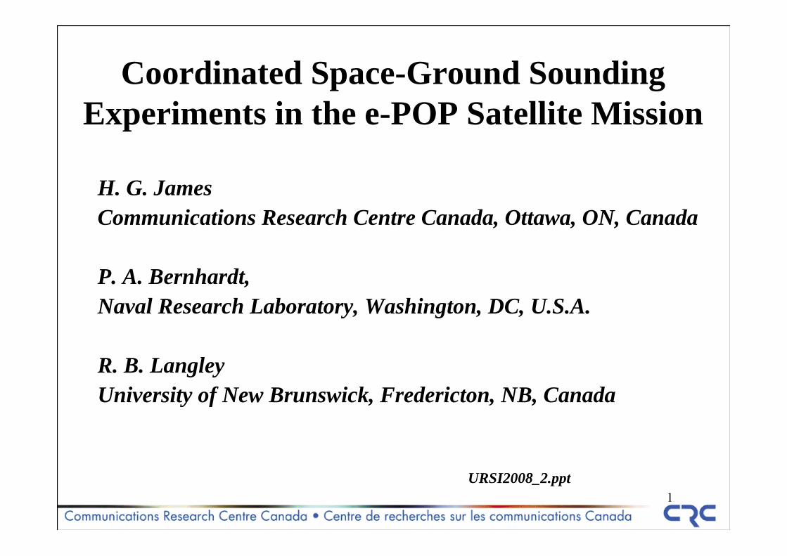
Coordinated Space-Ground Sounding Experiments in the e-POP Satellite Mission
H. G. JamesCommunications Research Centre Canada, Ottawa, ON, Canada
P. A. Bernhardt, Naval Research Laboratory, Washington, DC, U.S.A.
R. B. LangleyUniversity of New Brunswick, Fredericton, NB, Canada
URSI2008_2.ppt
2
Talk plan
1. Radio instruments on CASSIOPE/ePOP.2. Experiments coordinated with other facilities
3
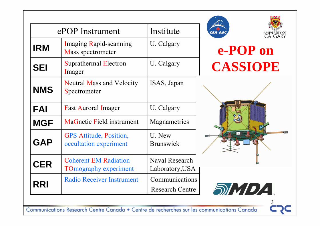
e-POP on CASSIOPE
CommunicationsResearch Centre
Radio Receiver InstrumentRRI
Naval Research Laboratory,USA
Coherent EM Radiation TOmography experimentCER
U. New Brunswick
GPS Attitude, Position, occultation experimentGAP
MagnametricsMaGnetic Field instrumentMGF
U. CalgaryFast Auroral ImagerFAI
ISAS, JapanNeutral Mass and Velocity SpectrometerNMS
U. CalgarySuprathermal Electron ImagerSEI
U. CalgaryImaging Rapid-scanning Mass spectrometerIRM
InstituteePOP Instrument
4
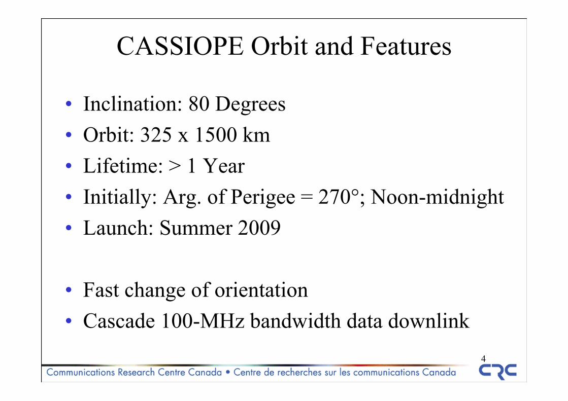
CASSIOPE Orbit and Features
• Inclination: 80 Degrees• Orbit: 325 x 1500 km• Lifetime: > 1 Year• Initially: Arg. of Perigee = 270°; Noon-midnight• Launch: Summer 2009
• Fast change of orientation • Cascade 100-MHz bandwidth data downlink
5
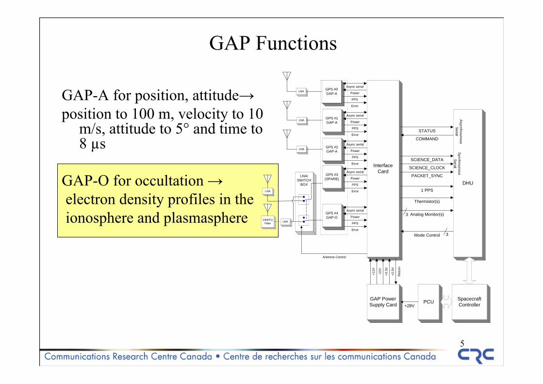
GAP Functions
GAP-A for position, attitude→position to 100 m, velocity to 10
m/s, attitude to 5° and time to 8 µs
GAP-O for occultation →electron density profiles in theionosphere and plasmasphere
LNA/SWITCH
BOX
LNA
GPS #0GAP-A
InterfaceCard
DHU
Async serial
SpacecraftController
1 PPS
Power
PPS
Error
GPS #1GAP-A
Async serial
Power
PPS
Error
LNA GPS #2GAP-A
Async serial
Power
PPS
Error
GPS #3(SPARE)
Async serial
Power
PPS
Error
LNA
GPS #4GAP-O
Async serial
Power
PPS
Error
Antenna Control
SycnhrounousS
erial
STATUS
COMMAND
SCIENCE_DATA
SCIENCE_CLOCK
PACKET_SYNC
Thermistor(s)
Analog Monitor(s)
PCU
Asycnhrounous
SerialLNA
LNA
GAP PowerSupply Card +28V
+12V
-12V
+3.3
V
+2.5
V
Ret
urn
Mode Control 3
3CERTO
Filter
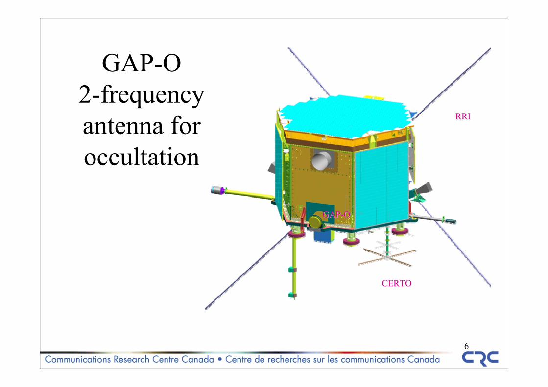
6
GAP-O 2-frequency antenna for occultation
GAPGAP--OO
CERTOCERTO
RRIRRI
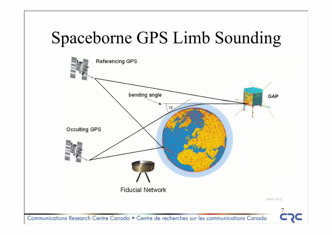
7
Spaceborne GPS Limb Sounding
(After GFZ)
GAP
8
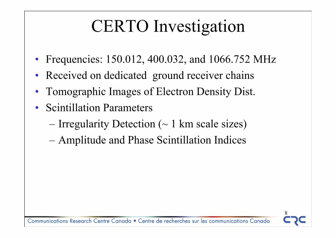
CERTO Investigation
• Frequencies: 150.012, 400.032, and 1066.752 MHz• Received on dedicated ground receiver chains• Tomographic Images of Electron Density Dist.• Scintillation Parameters
– Irregularity Detection (~ 1 km scale sizes)– Amplitude and Phase Scintillation Indices
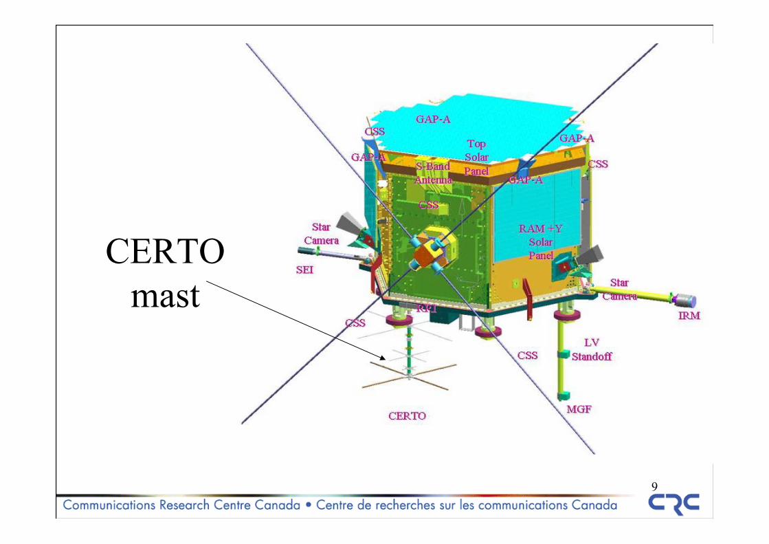
9
CERTO mast
10
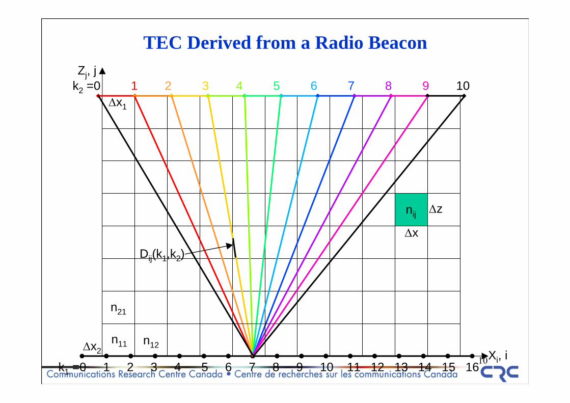
nij
TEC Derived from a Radio Beacon
Xi, i
Zj, j
k1 =0 1 2 3 4 5 6 7 8 9 10 11 12 13 14 15 16
k2 =0 1 2 3 4 5 6 7 8 9 10Δx1
Δx2
Δx
Δz
Dij(k1,k2)
n11 n12
n21
11
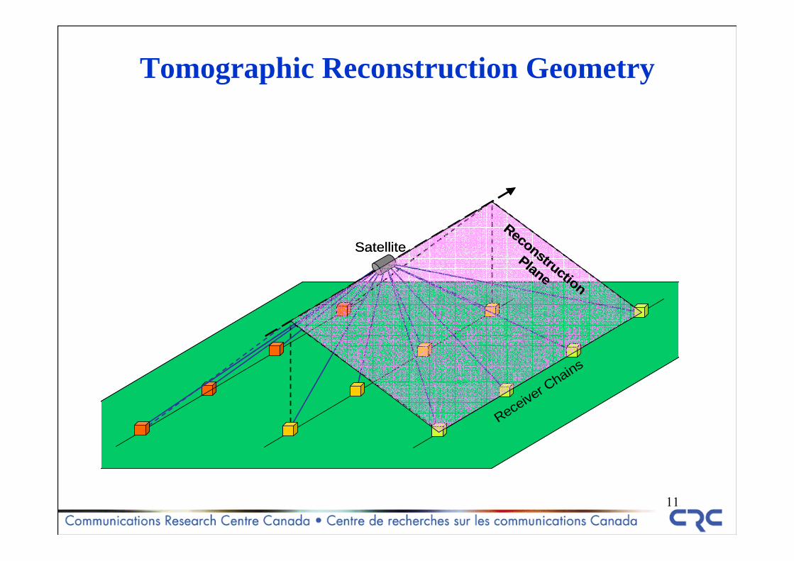
Tomographic Reconstruction Geometry
Satellite
Receiver C
hains
Reconstruction
Plane
Satellite
Receiver C
hains
Reconstruction
Plane
12
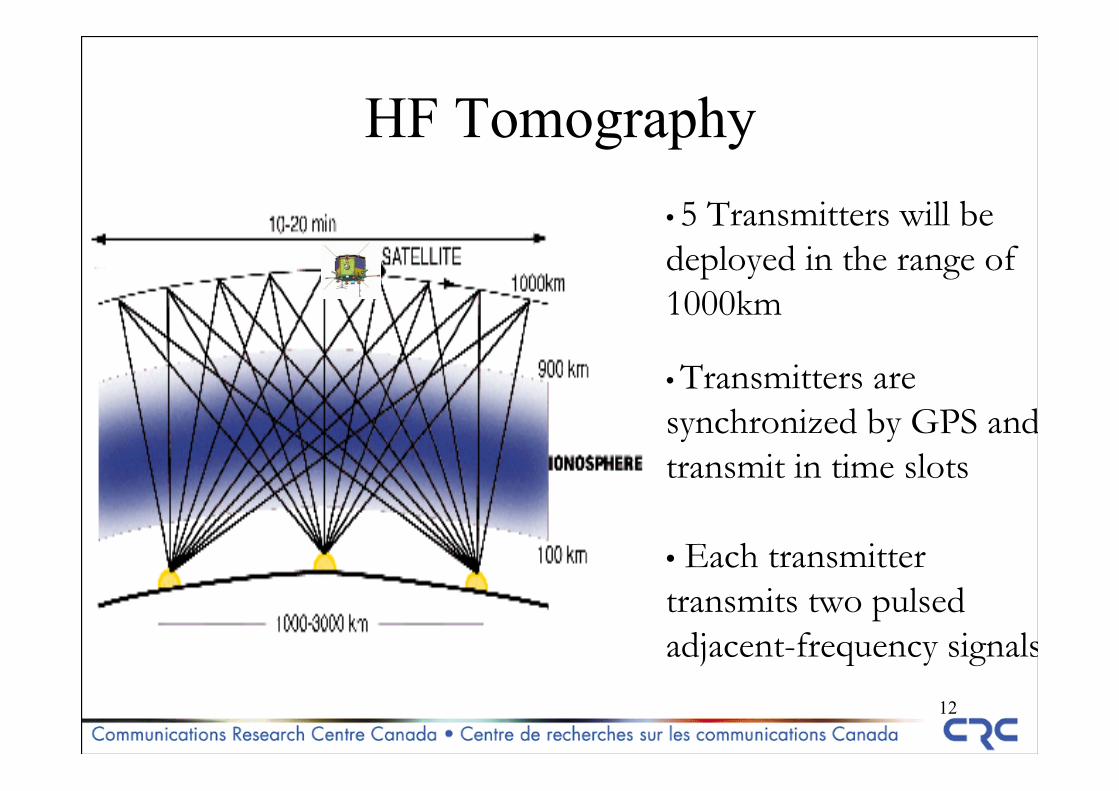
• 5 Transmitters will be deployed in the range of 1000km
• Transmitters are synchronized by GPS andtransmit in time slots
• Each transmitter transmits two pulsed adjacent-frequency signals
HF Tomography
13
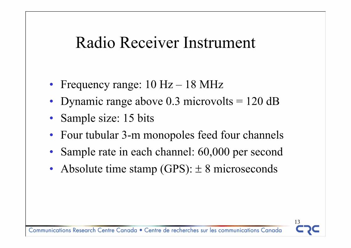
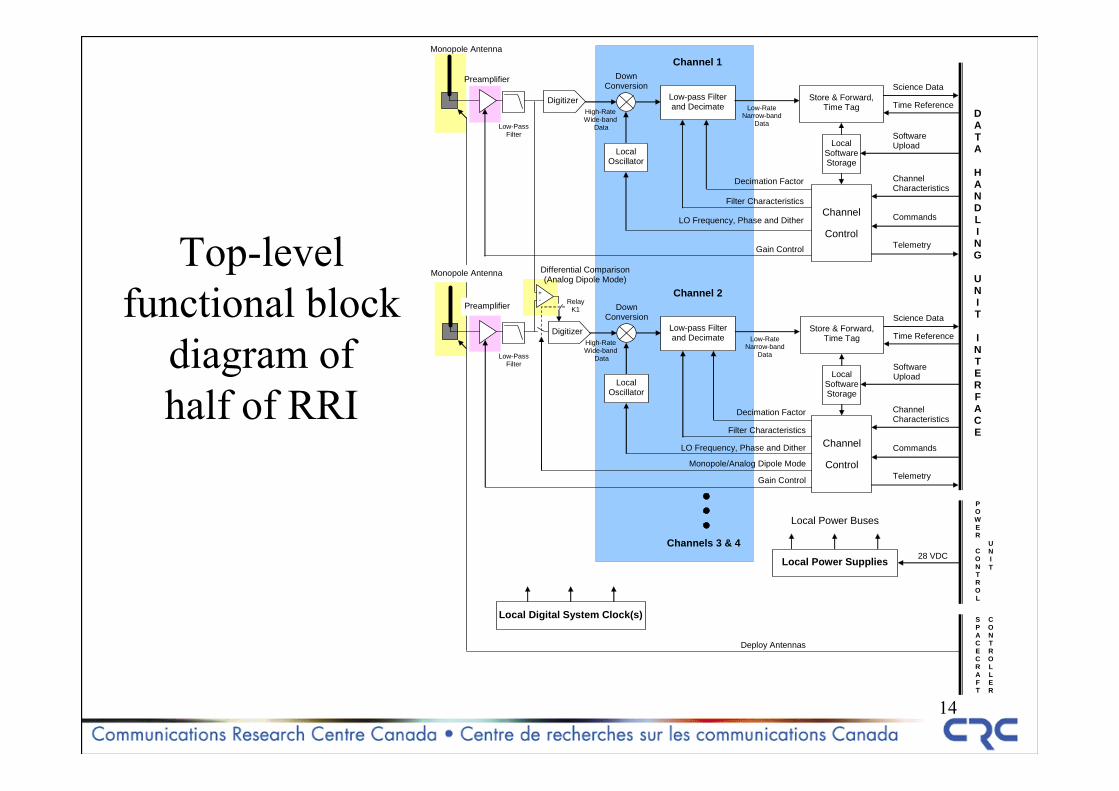
Radio Receiver Instrument
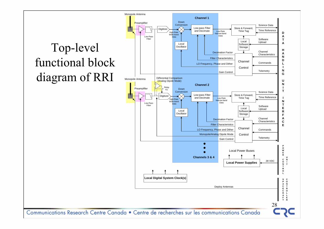
• Frequency range: 10 Hz – 18 MHz• Dynamic range above 0.3 microvolts = 120 dB• Sample size: 15 bits• Four tubular 3-m monopoles feed four channels• Sample rate in each channel: 60,000 per second• Absolute time stamp (GPS): ± 8 microseconds
14
Top-levelfunctional block
diagram of half of RRI
Software Upload
Digitizer
Preamplifier
Local Oscillator
Low-pass Filterand Decimate
Decimation Factor
Filter Characteristics
LO Frequency, Phase and Dither
Monopole Antenna
Gain Control
Down Conversion
Channel
Control
Store & Forward, Time Tag High-Rate
Wide-band Data
Low-Rate Narrow-band
Data
Science Data
Time Reference
Channel Characteristics
Channel 1
Local SoftwareStorage
Telemetry
Software Upload
Digitizer
Local Oscillator
Low-pass Filterand Decimate
Decimation Factor
Filter Characteristics
LO Frequency, Phase and Dither
Gain Control
Down Conversion
Channel
Control
Store & Forward, Time Tag High-Rate
Wide-band Data
Low-Rate Narrow-band
Data
Science Data
Time Reference
Channel 2
Local SoftwareStorage
D A T A
H A N D L I N G
U N I T I N T E R F A C E
28 VDC Local Power Supplies
Local Power Buses
Local Digital System Clock(s)
Channels 3 & 4
Deploy Antennas
Preamplifier
Monopole Antenna
Commands
Channel Characteristics
Telemetry
Commands
Low-Pass Filter
Low-Pass Filter
+ -
Differential Comparison (Analog Dipole Mode)
Monopole/Analog Dipole Mode
PO W E R
C O N T R O L
U N I T
SP A C E C R A F T
C O N T R O L L E R
Relay K1
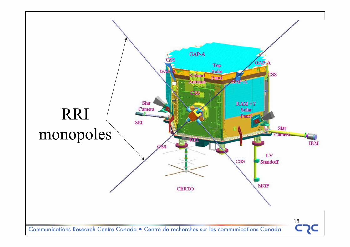
15
RRI monopoles
16-200 -100 0 100 200
-15
-10
-5
0
5
10
15
-200 -100 0 100 200
-3
-2
-1
0
1
2
3
4
-200 -100 0 100 200
-30
-20
-10
0
10
20
30
40
Ampl
itude
(dB)
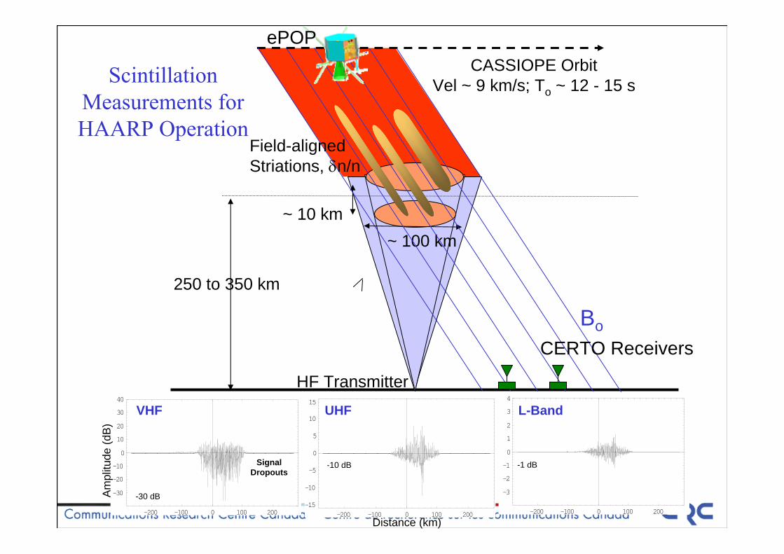
VHF UHF
-30 dB
-10 dB -1 dBSignal Dropouts
L-Band
Scintillation Measurements for HAARP Operation
250 to 350 km
~ 10 km~ 100 km
CASSIOPE OrbitVel ~ 9 km/s; To ~ 12 - 15 s
Bo
HF Transmitter
Field-alignedStriations, δn/n
CERTO Receivers
Distance (km)
ePOP
17
Talk plan
1. Radio instruments on CASSIOPE/ePOP.2. Experiments coordinated with other facilities
18
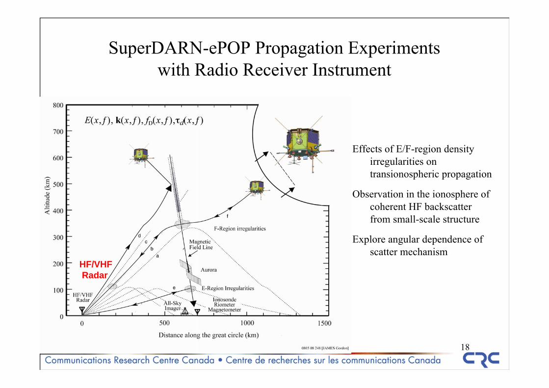
SuperDARN-ePOP Propagation Experimentswith Radio Receiver Instrument
HF/VHFRadar
e-POPreceiver
IonosphericIrregularities
Effects of E/F-region density irregularities on transionospheric propagation
Observation in the ionosphere of coherent HF backscatter from small-scale structure
Explore angular dependence of scatter mechanism
HF/VHFRadar
19
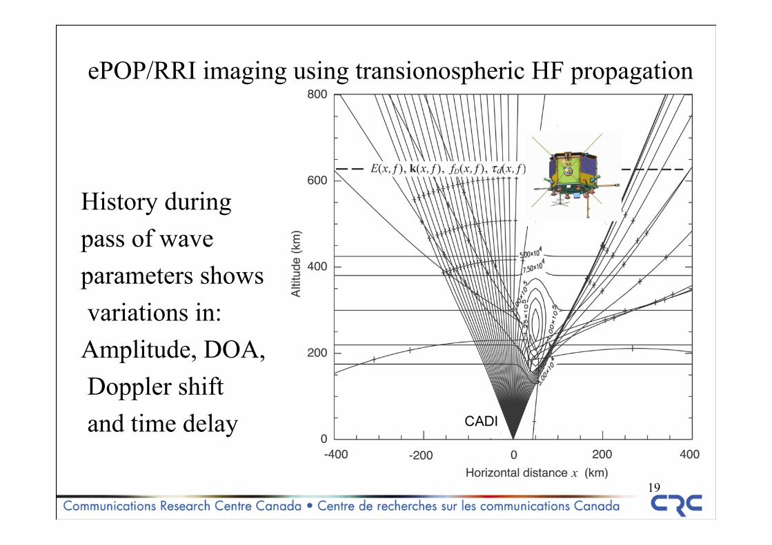
ePOP/RRI imaging using transionospheric HF propagation
History during pass of waveparameters showsvariations in:
Amplitude, DOA,Doppler shiftand time delay
20
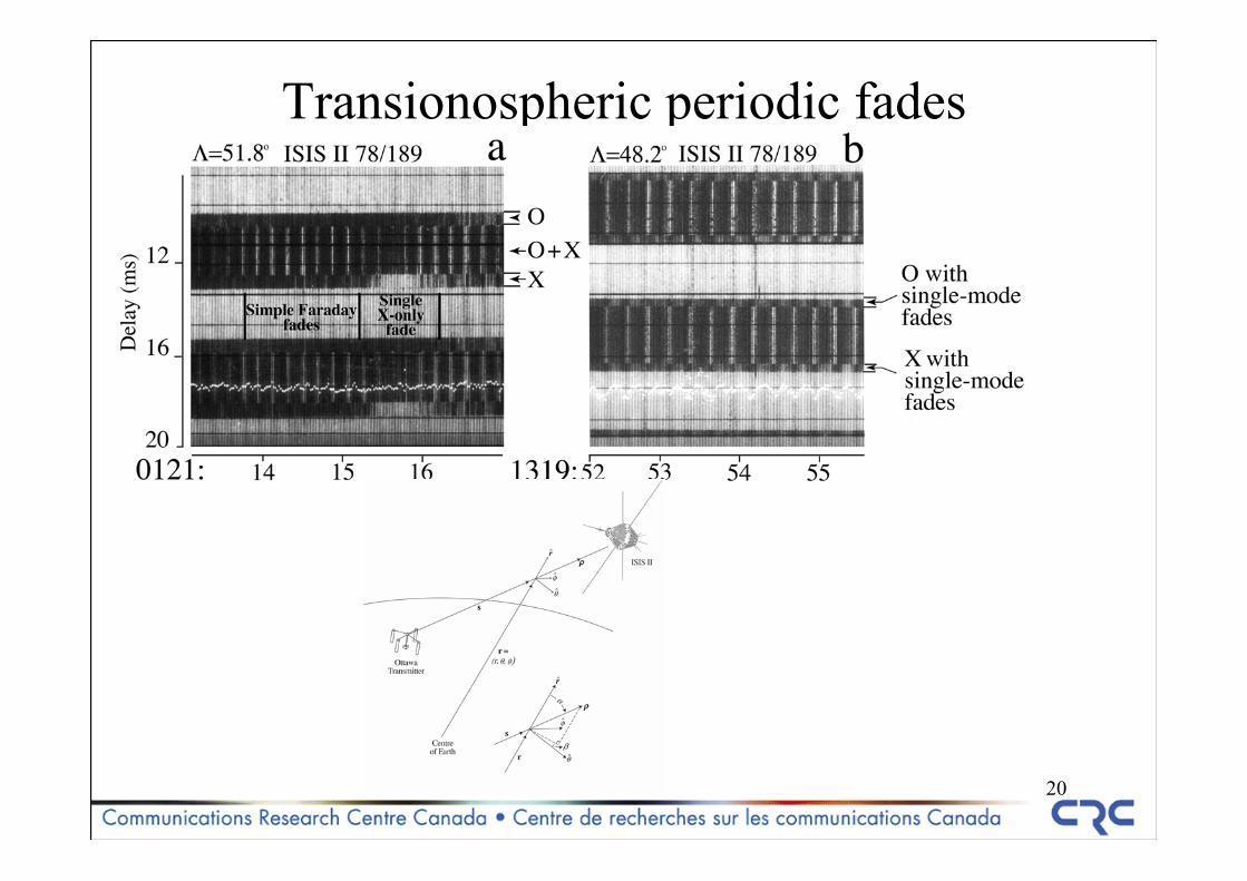
Transionospheric periodic fades
21
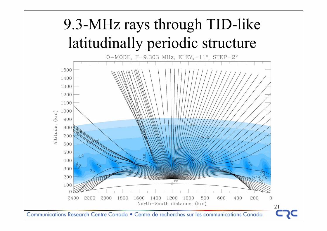
9.3-MHz rays through TID-like latitudinally periodic structure
22
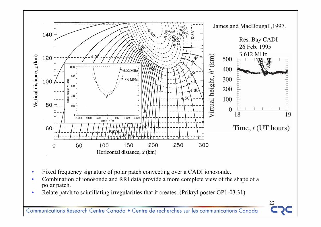
• Fixed frequency signature of polar patch convecting over a CADI ionosonde.• Combination of ionosonde and RRI data provide a more complete view of the shape of a
polar patch.• Relate patch to scintillating irregularities that it creates. (Prikryl poster GP1-03.31)
Res. Bay CADI26 Feb. 19953.612 MHz
James and MacDougall,1997.
23
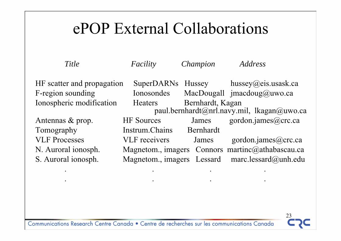
ePOP External Collaborations
Title Facility Champion Address
HF scatter and propagation SuperDARNs Hussey [email protected] sounding Ionosondes MacDougall [email protected] modification Heaters Bernhardt, Kagan
[email protected], [email protected] & prop. HF Sources James [email protected] Instrum.Chains BernhardtVLF Processes VLF receivers James [email protected]. Auroral ionosph. Magnetom., imagers Connors [email protected]. Auroral ionosph. Magnetom., imagers Lessard [email protected]
. . . .
. . . .
24
For more information about ePOPconsult:
http://mertensiana.phys.ucalgary.ca
25
26
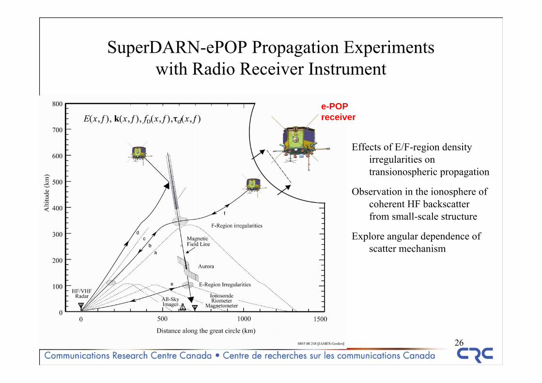
SuperDARN-ePOP Propagation Experimentswith Radio Receiver Instrument
Effects of E/F-region density irregularities on transionospheric propagation
Observation in the ionosphere of coherent HF backscatter from small-scale structure
Explore angular dependence of scatter mechanism
e-POPreceiver
27
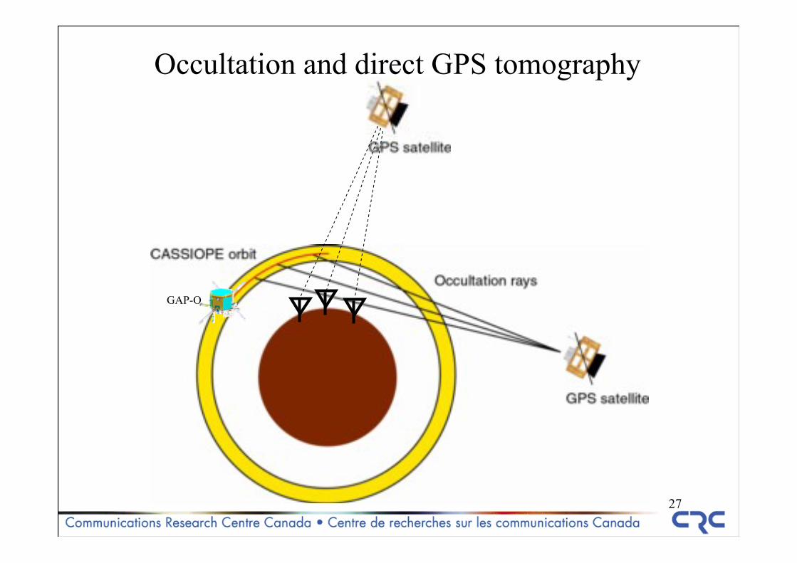
Occultation and direct GPS tomography
GAP-O
28
Top-levelfunctional block diagram of RRI
Software Upload
Digitizer
Preamplifier
Local Oscillator
Low-pass Filterand Decimate
Decimation Factor
Filter Characteristics
LO Frequency, Phase and Dither
Monopole Antenna
Gain Control
Down Conversion
Channel
Control
Store & Forward, Time Tag High-Rate
Wide-band Data
Low-Rate Narrow-band
Data
Science Data
Time Reference
Channel Characteristics
Channel 1
Local SoftwareStorage
Telemetry
Software Upload
Digitizer
Local Oscillator
Low-pass Filterand Decimate
Decimation Factor
Filter Characteristics
LO Frequency, Phase and Dither
Gain Control
Down Conversion
Channel
Control
Store & Forward, Time Tag High-Rate
Wide-band Data
Low-Rate Narrow-band
Data
Science Data
Time Reference
Channel 2
Local SoftwareStorage
D A T A
H A N D L I N G
U N I T I N T E R F A C E
28 VDC Local Power Supplies
Local Power Buses
Local Digital System Clock(s)
Channels 3 & 4
Deploy Antennas
Preamplifier
Monopole Antenna
Commands
Channel Characteristics
Telemetry
Commands
Low-Pass Filter
Low-Pass Filter
+ -
Differential Comparison (Analog Dipole Mode)
Monopole/Analog Dipole Mode
PO W E R
C O N T R O L
U N I T
SP A C E C R A F T
C O N T R O L L E R
Relay K1
29
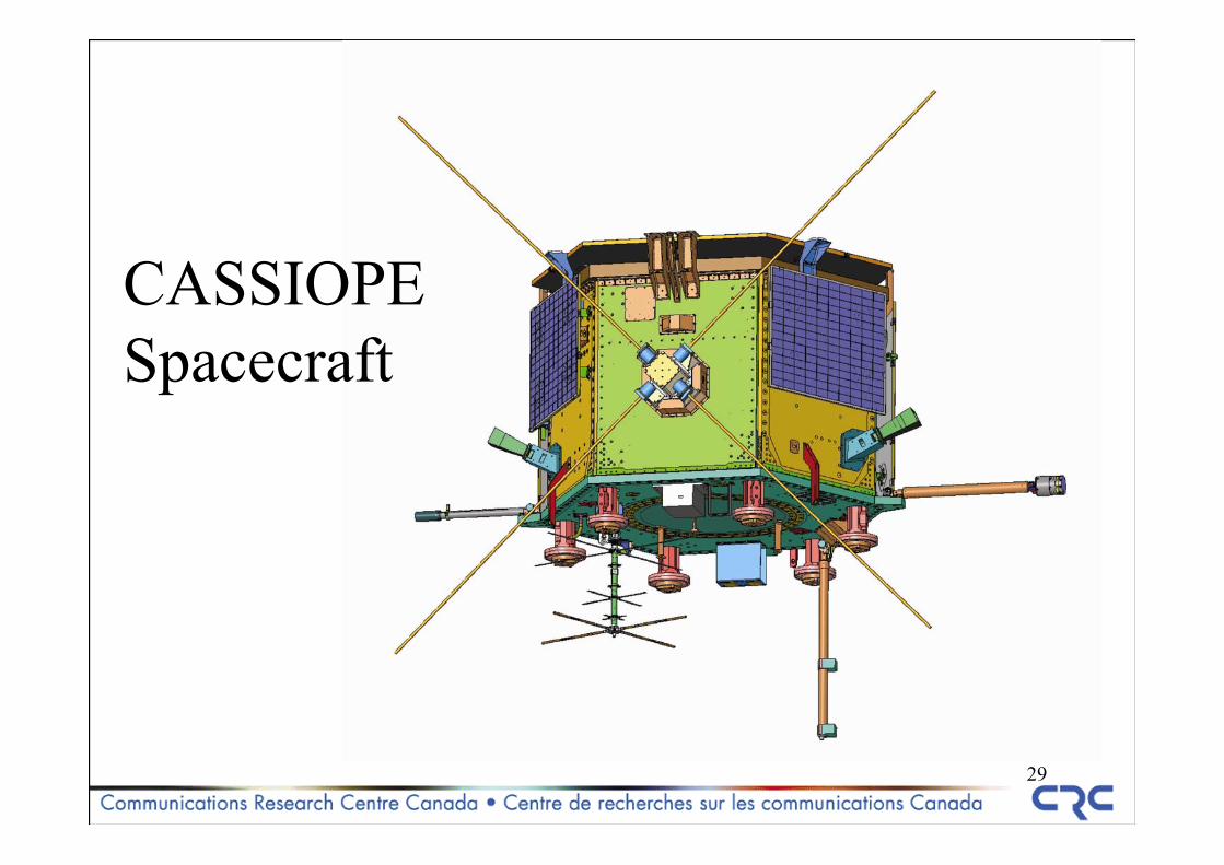
CASSIOPESpacecraft
30
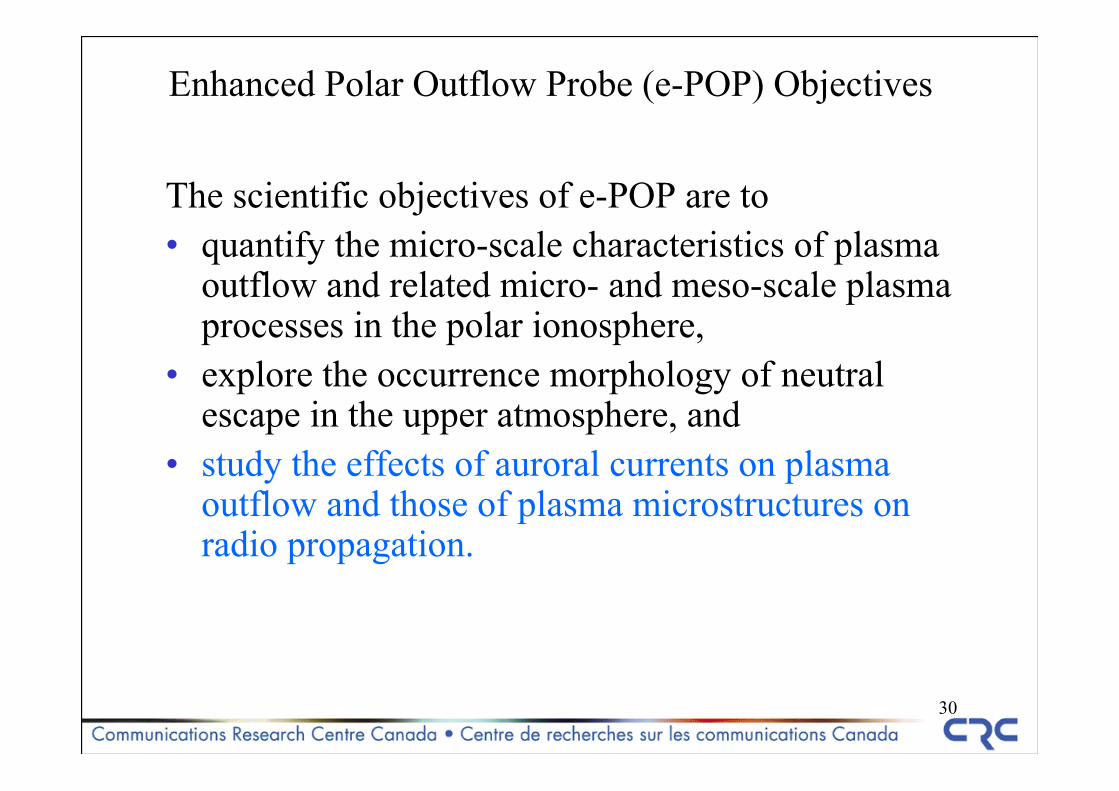
Enhanced Polar Outflow Probe (e-POP) Objectives
The scientific objectives of e-POP are to • quantify the micro-scale characteristics of plasma
outflow and related micro- and meso-scale plasma processes in the polar ionosphere,
• explore the occurrence morphology of neutral escape in the upper atmosphere, and
• study the effects of auroral currents on plasma outflow and those of plasma microstructures on radio propagation.
31
Summary on RRI in ePOP
Science agenda tries to cover both spontaneous and manmade sourcesDesign reflects technology objectives in software defined radioimportance for the understanding microscale physics.ePOP: exploits niche opportunities in Canada and elsewhere;
holds potential for payload inter-instrument investigations;works with gnd. facilities: imaging, scatter, nonlinearities; will maintain and improve a space-borne radio capability.
32
Rationale for ongoing space radioscience research
There is a world emphasis is on regional and global scales.Technologies and methodologies are not mature.History of plasma-wave investigations has demonstrated their
importance for the understanding microscale physics.ePOP: exploits niche opportunities in Canada and elsewhere;
holds potential for payload inter-instrument investigations;works with gnd. facilities: imaging, scatter, nonlinearities; will maintain and improve a space-borne radio capability.