Embed Size (px)
Citation preview
Cooperative Inchworm Localization with a Low Cost Team
Brian E. Nemsick, Austin D. Buchan, Anusha Nagabandi, Ronald S. Fearing, and Avideh Zakhor
Abstract— In this paper we address the problem of multi-robot localization with a heterogeneous team of low-cost mobilerobots. The team consists of a single centralized observer withan inertial measurement unit (IMU) and monocular camera,and multiple picket robots with only IMUs and Red Green Blue(RGB) light emitting diodes (LED). This team cooperativelynavigates a visually featureless environment while localizingall robots. A combination of camera imagery captured bythe observer and IMU measurements from the pickets andobserver are fused to estimate motion of the team. A teammovement strategy, referred to as inchworm, is formulatedas follows: Pickets move ahead of the observer and thenact as temporary landmarks for the observer to follow. Thiscooperative approach employs a single Extended Kalman Filter(EKF) to localize the entire heterogeneous multi-robot team,using a formulation of the measurement Jacobian to relatethe pose of the observer to the poses of the pickets withrespect to the global reference frame. An initial experimentwith the inchworm strategy has shown localization within 0.14m position error and 2.18 orientation error over a path-length of 5 meters in an environment with irregular ground,partial occlusions, and a ramp. This demonstrates improvementover a camera-only localization technique that was adaptedto our team dynamic which produced 0.18m position errorand 3.12 orientation error over the same dataset. In addition,we demonstrate improvement in localization accuracy with anincreasing number of picket robots.
I. INTRODUCTION
The size of a robot can greatly affect what it can doand where it can go. Advantages of small robots includeincreased accessibility and a wider range of capabilities suchas crawling through pipes, inspecting collapsed buildings,exploring congested or complex environments, and hiding insmall or inconspicuous spaces. However, these benefits alsobring along challenges in the form of reduced sensing abili-ties, lower communication capability, limited computationalresources, and tighter power constraints.
One way to overcome these limitations is to employ a het-erogeneous team [1] of collaborative robots. This approachmarks a design shift away from the traditional simultaneouslocalization and mapping (SLAM) ground robots that haveexpensive sensors and powerful processors, but less mobilityin disaster environments. The goal is to have small, mobile,disposable robots with limited capabilities collaborate andshare information to accomplish a larger task. Since eachrobot is expendable, reliability can be obtained in numbersbecause even if a single robot fails, few capabilities are
This work is supported by the National Science Foundation under theNational Robotics Initiative, Award 1427096.
The authors are with Department of Electrical Engineering andComputer Sciences, University of California, Berkeley, CA 94720 USAbrian.nemsick, abuchan, nagaban2, ronf, [email protected]
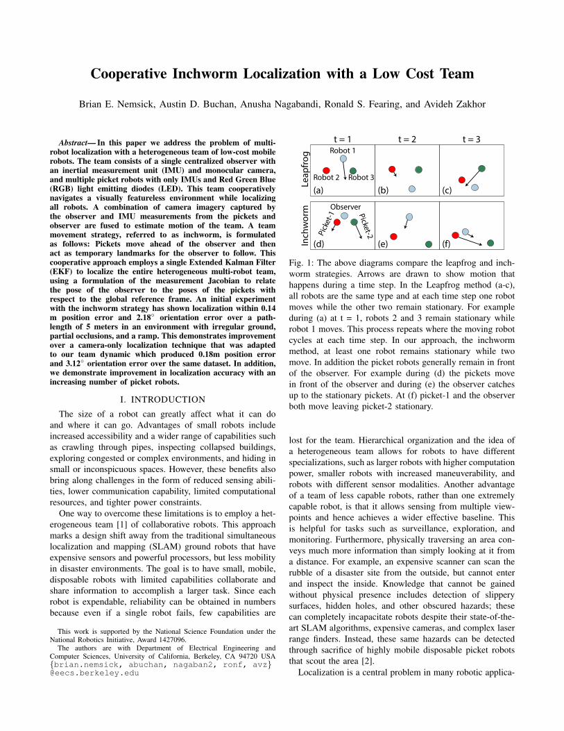
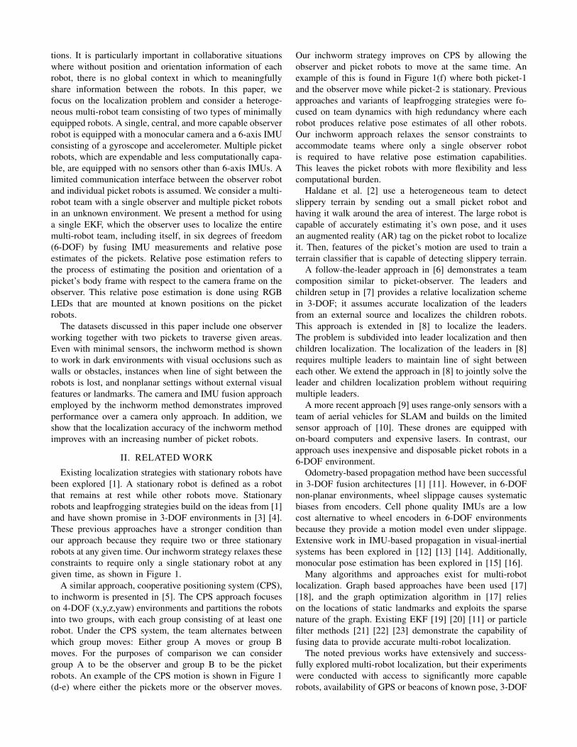
(a) (b) (c)
Leap
frog
Robot 2
Robot 1
Robot 3
(d)Inch
wor
m
Pick
et-1
ObserverPicket-2
(e) (f)
t = 1 t = 2 t = 3
Fig. 1: The above diagrams compare the leapfrog and inch-worm strategies. Arrows are drawn to show motion thathappens during a time step. In the Leapfrog method (a-c),all robots are the same type and at each time step one robotmoves while the other two remain stationary. For exampleduring (a) at t = 1, robots 2 and 3 remain stationary whilerobot 1 moves. This process repeats where the moving robotcycles at each time step. In our approach, the inchwormmethod, at least one robot remains stationary while twomove. In addition the picket robots generally remain in frontof the observer. For example during (d) the pickets movein front of the observer and during (e) the observer catchesup to the stationary pickets. At (f) picket-1 and the observerboth move leaving picket-2 stationary.
lost for the team. Hierarchical organization and the idea ofa heterogeneous team allows for robots to have differentspecializations, such as larger robots with higher computationpower, smaller robots with increased maneuverability, androbots with different sensor modalities. Another advantageof a team of less capable robots, rather than one extremelycapable robot, is that it allows sensing from multiple view-points and hence achieves a wider effective baseline. Thisis helpful for tasks such as surveillance, exploration, andmonitoring. Furthermore, physically traversing an area con-veys much more information than simply looking at it froma distance. For example, an expensive scanner can scan therubble of a disaster site from the outside, but cannot enterand inspect the inside. Knowledge that cannot be gainedwithout physical presence includes detection of slipperysurfaces, hidden holes, and other obscured hazards; thesecan completely incapacitate robots despite their state-of-the-art SLAM algorithms, expensive cameras, and complex laserrange finders. Instead, these same hazards can be detectedthrough sacrifice of highly mobile disposable picket robotsthat scout the area [2].
Localization is a central problem in many robotic applica-
tions. It is particularly important in collaborative situationswhere without position and orientation information of eachrobot, there is no global context in which to meaningfullyshare information between the robots. In this paper, wefocus on the localization problem and consider a heteroge-neous multi-robot team consisting of two types of minimallyequipped robots. A single, central, and more capable observerrobot is equipped with a monocular camera and a 6-axis IMUconsisting of a gyroscope and accelerometer. Multiple picketrobots, which are expendable and less computationally capa-ble, are equipped with no sensors other than 6-axis IMUs. Alimited communication interface between the observer robotand individual picket robots is assumed. We consider a multi-robot team with a single observer and multiple picket robotsin an unknown environment. We present a method for usinga single EKF, which the observer uses to localize the entiremulti-robot team, including itself, in six degrees of freedom(6-DOF) by fusing IMU measurements and relative poseestimates of the pickets. Relative pose estimation refers tothe process of estimating the position and orientation of apicket’s body frame with respect to the camera frame on theobserver. This relative pose estimation is done using RGBLEDs that are mounted at known positions on the picketrobots.
The datasets discussed in this paper include one observerworking together with two pickets to traverse given areas.Even with minimal sensors, the inchworm method is shownto work in dark environments with visual occlusions such aswalls or obstacles, instances when line of sight between therobots is lost, and nonplanar settings without external visualfeatures or landmarks. The camera and IMU fusion approachemployed by the inchworm method demonstrates improvedperformance over a camera only approach. In addition, weshow that the localization accuracy of the inchworm methodimproves with an increasing number of picket robots.
II. RELATED WORK
Existing localization strategies with stationary robots havebeen explored [1]. A stationary robot is defined as a robotthat remains at rest while other robots move. Stationaryrobots and leapfrogging strategies build on the ideas from [1]and have shown promise in 3-DOF environments in [3] [4].These previous approaches have a stronger condition thanour approach because they require two or three stationaryrobots at any given time. Our inchworm strategy relaxes theseconstraints to require only a single stationary robot at anygiven time, as shown in Figure 1.
A similar approach, cooperative positioning system (CPS),to inchworm is presented in [5]. The CPS approach focuseson 4-DOF (x,y,z,yaw) environments and partitions the robotsinto two groups, with each group consisting of at least onerobot. Under the CPS system, the team alternates betweenwhich group moves: Either group A moves or group Bmoves. For the purposes of comparison we can considergroup A to be the observer and group B to be the picketrobots. An example of the CPS motion is shown in Figure 1(d-e) where either the pickets more or the observer moves.
Our inchworm strategy improves on CPS by allowing theobserver and picket robots to move at the same time. Anexample of this is found in Figure 1(f) where both picket-1and the observer move while picket-2 is stationary. Previousapproaches and variants of leapfrogging strategies were fo-cused on team dynamics with high redundancy where eachrobot produces relative pose estimates of all other robots.Our inchworm approach relaxes the sensor constraints toaccommodate teams where only a single observer robotis required to have relative pose estimation capabilities.This leaves the picket robots with more flexibility and lesscomputational burden.
Haldane et al. [2] use a heterogeneous team to detectslippery terrain by sending out a small picket robot andhaving it walk around the area of interest. The large robot iscapable of accurately estimating it’s own pose, and it usesan augmented reality (AR) tag on the picket robot to localizeit. Then, features of the picket’s motion are used to train aterrain classifier that is capable of detecting slippery terrain.
A follow-the-leader approach in [6] demonstrates a teamcomposition similar to picket-observer. The leaders andchildren setup in [7] provides a relative localization schemein 3-DOF; it assumes accurate localization of the leadersfrom an external source and localizes the children robots.This approach is extended in [8] to localize the leaders.The problem is subdivided into leader localization and thenchildren localization. The localization of the leaders in [8]requires multiple leaders to maintain line of sight betweeneach other. We extend the approach in [8] to jointly solve theleader and children localization problem without requiringmultiple leaders.
A more recent approach [9] uses range-only sensors with ateam of aerial vehicles for SLAM and builds on the limitedsensor approach of [10]. These drones are equipped withon-board computers and expensive lasers. In contrast, ourapproach uses inexpensive and disposable picket robots in a6-DOF environment.
Odometry-based propagation method have been successfulin 3-DOF fusion architectures [1] [11]. However, in 6-DOFnon-planar environments, wheel slippage causes systematicbiases from encoders. Cell phone quality IMUs are a lowcost alternative to wheel encoders in 6-DOF environmentsbecause they provide a motion model even under slippage.Extensive work in IMU-based propagation in visual-inertialsystems has been explored in [12] [13] [14]. Additionally,monocular pose estimation has been explored in [15] [16].
Many algorithms and approaches exist for multi-robotlocalization. Graph based approaches have been used [17][18], and the graph optimization algorithm in [17] relieson the locations of static landmarks and exploits the sparsenature of the graph. Existing EKF [19] [20] [11] or particlefilter methods [21] [22] [23] demonstrate the capability offusing data to provide accurate multi-robot localization.
The noted previous works have extensively and success-fully explored multi-robot localization, but their experimentswere conducted with access to significantly more capablerobots, availability of GPS or beacons of known pose, 3-DOF
Algorithm 1: Cooperative Inchworm Localization (EKF)Propagation: For each IMU measurement:• buffer previous IMU measurements received from
other robots• propagate state and covariance for the team using the
time-step, buffer and new IMU measurement (cf.Section III-B).
Update: For each camera image:• identify RGB LEDs (cf. Section III-C).• estimate the relative pose between the visible picket
robots and the observer frame with P3P and GaussNewton minimization (cf. Section III-C).
• propagate the state and covariance for the team usingthe time-step, and most recent IMU measurements
• perform state and covariance update for the team (cf.Section III-D, III-E).
Inchworm requirement: At least one stationary robot
settings with planar environmental assumptions and accuratewheel odometry, requirements of additional stationary robots,assumptions of light, and existence of landmarks or visualfeatures. In this paper, we relax these assumptions to localizea team consisting of a single observer robot and multiplepicket robots. This is accomplished using an EKF approachwith the inchworm strategy requirement of at least a singlestationary robot at all times. IMU measurements are used forEKF propagation and relative pose estimates are used as anEKF update.
III. METHODS
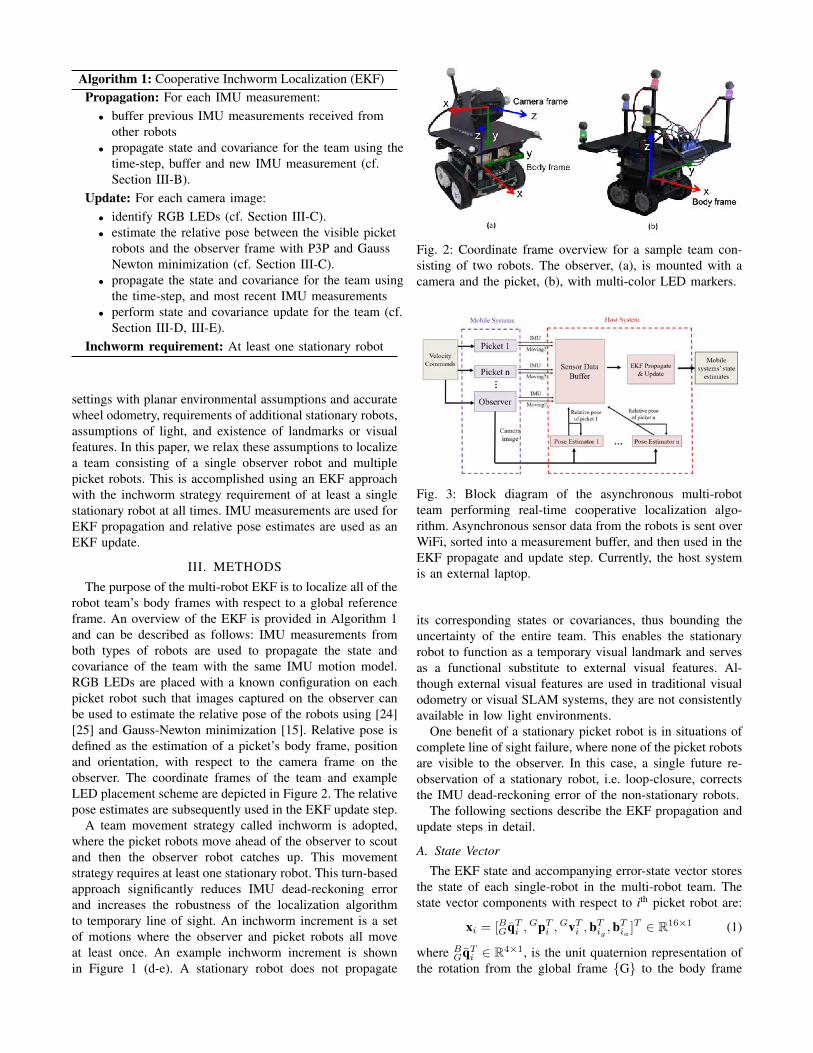
The purpose of the multi-robot EKF is to localize all of therobot team’s body frames with respect to a global referenceframe. An overview of the EKF is provided in Algorithm 1and can be described as follows: IMU measurements fromboth types of robots are used to propagate the state andcovariance of the team with the same IMU motion model.RGB LEDs are placed with a known configuration on eachpicket robot such that images captured on the observer canbe used to estimate the relative pose of the robots using [24][25] and Gauss-Newton minimization [15]. Relative pose isdefined as the estimation of a picket’s body frame, positionand orientation, with respect to the camera frame on theobserver. The coordinate frames of the team and exampleLED placement scheme are depicted in Figure 2. The relativepose estimates are subsequently used in the EKF update step.
A team movement strategy called inchworm is adopted,where the picket robots move ahead of the observer to scoutand then the observer robot catches up. This movementstrategy requires at least one stationary robot. This turn-basedapproach significantly reduces IMU dead-reckoning errorand increases the robustness of the localization algorithmto temporary line of sight. An inchworm increment is a setof motions where the observer and picket robots all moveat least once. An example inchworm increment is shownin Figure 1 (d-e). A stationary robot does not propagate
Fig. 2: Coordinate frame overview for a sample team con-sisting of two robots. The observer, (a), is mounted with acamera and the picket, (b), with multi-color LED markers.
Fig. 3: Block diagram of the asynchronous multi-robotteam performing real-time cooperative localization algo-rithm. Asynchronous sensor data from the robots is sent overWiFi, sorted into a measurement buffer, and then used in theEKF propagate and update step. Currently, the host systemis an external laptop.
its corresponding states or covariances, thus bounding theuncertainty of the entire team. This enables the stationaryrobot to function as a temporary visual landmark and servesas a functional substitute to external visual features. Al-though external visual features are used in traditional visualodometry or visual SLAM systems, they are not consistentlyavailable in low light environments.
One benefit of a stationary picket robot is in situations ofcomplete line of sight failure, where none of the picket robotsare visible to the observer. In this case, a single future re-observation of a stationary robot, i.e. loop-closure, correctsthe IMU dead-reckoning error of the non-stationary robots.
The following sections describe the EKF propagation andupdate steps in detail.
A. State Vector
The EKF state and accompanying error-state vector storesthe state of each single-robot in the multi-robot team. Thestate vector components with respect to ith picket robot are:
xi = [BGqTi ,
GpTi ,
GvTi ,b
Tig ,b
Tia ]T ∈ R16×1 (1)
where BGqT
i ∈ R4×1, is the unit quaternion representation ofthe rotation from the global frame G to the body frame
B, Gpi,Gvi ∈ R3×1 are the body frame position and
velocity with respect to the global frame, and big ,bia ∈R3×1 are the gyroscope and accelerometer biases.
The corresponding error-state components with respect toith picket robot are:
xi = [GθT
i ,GpT
i ,GvT
i , bT
ig , bT
ia ]T ∈ R15×1 (2)
where GθT
i is the minimal representation from the errorquaternion δq ' [ 12
GθT, 1]T [13] [14]. The non-quaternion
states use the standard additive error model.The observer robot is also a component in the EKF state
and error-state vector:
xo = [OGqTo ,
GpTo ,
GvTo ,bTog ,b
Toa ]T ∈ R16×1
xo = [GθT,GpT
o ,GvT
o , bT
og , bT
oa ]T ∈ R15×1(3)
where O denotes the observer frame.Combining the states in Eqns. 1, 2, and 3, the augmented
EKF state vector and error-state vector with respect to themulti-robot team with n pickets becomes:
x = [xTo , xT1 , x
T2 , ... xTn ]T ∈ R16(n+1)×1
x = [xTo xT1 , xT2 , ... xTn ]T ∈ R15(n+1)×1 (4)
where n is the total number of picket robots.
B. IMU Propagation Model
The EKF propagation step occurs each time a new IMUmeasurement from any single-robot or a camera image iscaptured on the observer robot. The continuous dynamics ofthe IMU propagation model for a single-robot are [13] [14]:
BGq =
1
2Ω(ω)BGq, Gp = Gv, Gv = Ga
bg = nwg, ba = nwa
(5)
where nwg,nwa are Gaussian white noise vectors for thegyroscope and accelerometer respectively and
bω×c =
[0 −ωz ωy
ωz 0 −ωx−ωy ωx 0
],Ω(ω) =
[−bω×c ω−ωT 0
](6)
The discrete time linearized model and the error-statemodel are derived and discussed with detail in [13] [14].
Critically, stationary robots receive no state or covariancepropagation. This prevents IMU dead-reckoning drift frommoving a temporary landmark and maintains a boundedcovariance block pertaining to the stationary robot.
C. Relative Pose Estimation
Four (or more) RGB LEDs are placed at known config-urations position on the picket robots to allow relative poseestimation on board the observer. Each picket robot receivesa unique configuration with LEDs of various colors. Colorand intensity thresholds are used to find the LED centroids,and these LED detections are passed into separate poseestimators (one pose estimator for each robot).
From the centroid detections, the approach from [15] isused to perform relative pose estimation. Pose correspon-dence is computed with the perspective-3-point (P3P) [24]
[25] algorithm for each picket. Using different colors for theLEDs reduces the computational load by allowing the P3Pcorrespondence search to search fewer possible configura-tions. Gauss-Newton minimization refines the initial solutionfrom the P3P algorithm by minimizing reprojection error[15]:
P ∗ = arg minP
∑<l,d>∈C
||π(l,P− d)||2
where P is pose estimate, l is the set of LED configurations,d is the set of LED centroids, C is the LED correspondences,and π projects an LED from R3 into R2 (camera image).
The pose estimate covariance (Q) is calculated with theJacobian (J) from the Gauss-Newton minimization [15]:
Q = (JT Σ−1J)−1 where Σ = I2×2 pixels2 (7)
D. Camera Measurement Model
In this section we describe how the relative pose estimatesare used to compute the EKF update. We derive the residualand observation matrix that relates the relative pose estimatesto the state vector as described in Section III-A. The residualand the observation matrix are used to calculate the Kalmangain and correction.
An example overview of the multi-robot teams coordinatesframes is shown in Figure 2. A static camera transform isdefined as:
[COqT ,COpT ]T ∈ R7×1 (8)
With respect to a single visible picket robot, i, a relativepose estimate from the camera frame on board the observeris defined as:
zi = [BC qTiz,BCpT
iz]T ∈ R7×1 (9)
In an EKF framework, a residual, r, and a measurementJacobian, H are used to compute the EKF update. Thestandard relationship between the residual and measurementJacobian is:
r = z− z ≈ Hx + n (10)
where n is noise. A prediction of the observation, zi, is usedto compute a residual in an EKF. This observation corre-sponds to a relative pose for each visible robot. Additionally,the quaternion states in x use the rotational error definition,δq = q⊗q−1 rather than the standard linear error, p = p−p.
To compute zi, the state vector estimate is updated withthe EKF propagation step. The poses of the picket robotsare then converted from the global frame converted to thecamera coordinate frame, C, in Eq. 8 to match the relativepose estimate:
zi =
[BC
ˆqiBC pi
]=
[BG
ˆqi ⊗ GO
ˆqO ⊗ OC
ˆqOCORO
GR(BGpi − OGpO − C
Op)
](11)
where ⊗ represents quaternion multiplication.The single-robot residuals with respect to each visible
pickets robots are calculated according to the definition Eq.10:
ri = zi − zi =
[2 · π(BC ˆq−1i ⊗ B
C qiz)
BCpiz
− BC pi
](12)
where π is defined as π([qx, qy, qz, qw]T )T = [qx, qy, qz]T
and utilized as a small angle approximation for the orienta-tion difference between zi and zi.
The ith measurement Jacobian, Hi, is calculated by ap-plying small angle approximations and taking the partialderivatives of the ith single-robot residual with respect tothe error-state. The non-zero entries are shown below:
ri ' Hix
Hi =[
−CGR 0 0 . . . C
GR 0 0 . . .CGRb(BG pi −
OG pO −
COp)×c −C
GR 0 . . . 0 CGR 0 . . .
]x =
[Gθo
GpoGvo · · · Gθi
GpiGvi · · ·
](13)
where CGR = C
OROGR and bq×c is the quaternion skew
operator from Eq. 6. The higher order and cross terms aredropped from Hi to satisfy the linear requirement of the EKF.
The states of all picket robots become correlated with theobserver robot through the measurement Jacobian. This en-ables an individual pose estimate of a picket robot to improvethe state estimate of each picket robot. The correlation isessential to localizing the observer robot because it is unableto observe itself directly from camera imagery.
E. EKF Update
From the camera measurement model the EKF updateis performed. To utilize the standard equations, the overallmeasurement Jacobian is calculated by vertically stackingthe single-robot measurement Jacobians from the camerameasurement model in Eq. 13:
H = [HT1 ,H
T2 , ... HT
n ]T ∈ R6n×16(n+1) (14)
Accordingly the measurements, zi, are stacked identically:
z = [zT1 , zT2 , ... zTn ]T ∈ R7n×1 (15)
The corresponding overall observation noise is calculatedby diagonalizing the uncorrelated relative pose estimatecovariances from Eq. 7:
Q = diag(Q1,Q2, ... Qn) ∈ R6n×6n (16)
From Eqs. 14, 15, and 16, the procedure to update an EKFwith quaternion states is described in [13] [14].
IV. RESULTS
A. Experimental Approach
We apply the localization technique described above todata collected from a team of three small, low-cost, mobilerobots. The Zumy robot1 is a decimeter-scale tracked robotrunning ROS on board a Linux computing system withnetworking and vision processing capabilities. The observerZumy supports a Microsoft Lifecam 3000 webcam with
1https://wiki.eecs.berkeley.edu/biomimetics/Main/Zumy
640× 480 pixels2 at 30 Hz, InvenSense MPU-6050 MEMSIMU at 30 Hz, and supports WiFi wireless communication.This robot is designed to be easily built from commerciallyavailable off-the-shelf parts for a total cost of ≈ $350.
The robotic team consists of one observer and two picketrobots shown in Figure 2. A Zumy robot with a camera servesas the observer, and to represent the inexpensive and lesscapable picket robots, we use Zumy robots without cameras.Each picket robot is outfitted with an LED “hat” so that it canbe visually tracked by the observer robot. Infrared markersare also attached to each Zumy in order to obtain groundtruth from a VICON motion capture system. The robots aremanually driven for these datasets.
B. Planar Base Case
The baseline experimental task was a cooperative U-turnin planar 3-DOF with one observer and two pickets. Therobots were manually driven in the dark. Although the datasetwas recorded in a 3-DOF environment, the filter was notconstrained with environmental priors. A direct comparisonbetween the LED pose tracker system setup in [15] and oursystem setup is in Table I.
TABLE I: Pose Tracker Comparison
Faessler et al. [15] Our System
Resolution (pixels2) 752x480 640x480Baseline Radius (cm) 10.9 10.6
LEDs/Robot 5 5LED Type Infared RGB
≈ error at 2 m depth 5 cm, 1-2 deg 5-8 cm, 1-4 deg
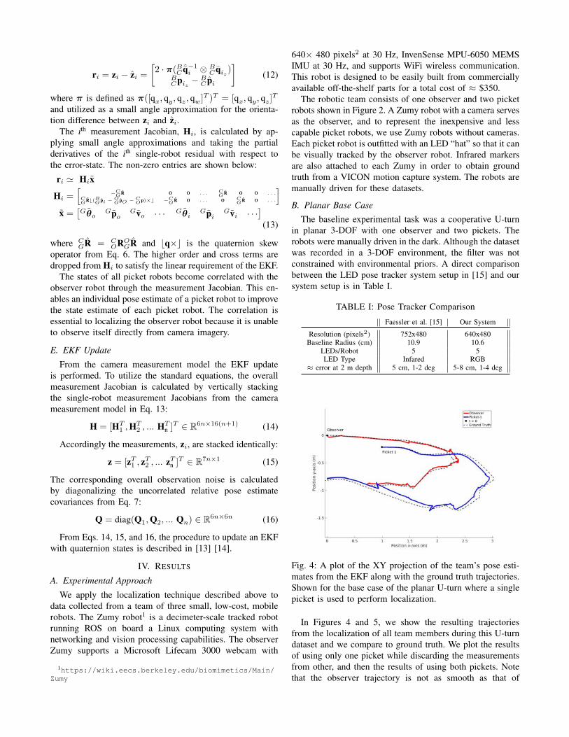
Fig. 4: A plot of the XY projection of the team’s pose esti-mates from the EKF along with the ground truth trajectories.Shown for the base case of the planar U-turn where a singlepicket is used to perform localization.
In Figures 4 and 5, we show the resulting trajectoriesfrom the localization of all team members during this U-turndataset and we compare to ground truth. We plot the resultsof using only one picket while discarding the measurementsfrom other, and then the results of using both pickets. Notethat the observer trajectory is not as smooth as that of

Fig. 5: A plot of the XY projection of the team’s pose esti-mates from the EKF along with the ground truth trajectories.Shown for the base case of the planar U-turn where bothpickets are used to perform localization.
Fig. 6: Camera-only approach: A plot of the XY projectionof the team’s pose estimates along with the ground truthtrajectories, using a camera-only approach. Performs notablyworse in yaw drift than the IMU-camera fusion approachshown in Figures 4, 5.
TABLE II: Planar Drift Analysis
Camera-only Fusion FusionTwo Pickets One Picket Two Pickets
Obs
erve
r x (cm) -8.14 0.67 -0.80y (cm) 16.64 2.58 -1.46z (cm) 4.09 -5.42 3.07
Angle () 9.33 1.89 1.54
Pick
et-1 x (cm) -13.38 -4.25 -6.23
y (cm) 28.97 -1.79 -1.70z (cm) 4.53 -7.91 4.39
Angle () 4.72 2.64 1.36
Pick
et-2 x (cm) -1.35 - 9.92
y (cm) 25.40 - -5.65z (cm) 4.56 - 5.18
Angle () 4.56 - 1.88
picket-1 or picket-2, because the motion of the observerhas un-modeled vibration effects that cause motion blur andtemporary changes to the “static” camera transform.
This dataset consisted of 10 inchworm increments. Aninchworm increment is defined as the minimal set of teammotions where each robots has moved once. End-position
drift for using a single picket vs. using two pickets are shownin Table II. The angular drift, which causes propagates errorinto the future, for the two picket fusion case was less thanthe one picket case. Although unconstrained to a plane, theangular drift was almost exclusively in yaw. Performing rightor left turns with the robot team introduces more rotationaldrift than forward or backwards motions. Without externalfeatures or global correction, the yaw errors persist until theend of experiment, but adding more picket robots helps tomitigate these effects. The jagged regions of the trajectorycorrespond to the observer and picket robots starting orstopping motion, and they are due to The LED mounts andthe robots shaking during these transient motions.
A camera-only filtering approach was evaluated in Figure6 as a baseline. The camera-only approach uses the sameformulation of the measurement derived in Section III-Dbut without a motion model. This method performed sig-nificantly worse with four times as much yaw drift than theIMU plus camera fusion approach. Without the gyroscope,the inchworm localization performs significantly worse inorientation estimation.
C. Non-planar Terrain with Ramp
Fig. 7: 6-DOF environment for testing: Robot team is on theright, rock garden is center-right), a “hole” is shown on thebottom-left, and the ramp is on top left.
The second experiment was conducted in an environmentfeaturing non-planar terrain, obstacles, and occlusions. Therobots were manually driven in the environment shown inFigure 7. The 6-DOF non-planar dataset consisted of 10inchworm increments: 3 for the rock garden and 7 forthe right turn and ramp. Temporary line of sight failureof both pickets occurred during the rock garden becausethe pose estimator failed to converge, as the observer wasmoving on the rocks. Wheel slippage also occurred duringthe rock garden section. After the rock garden, picket-2 wasdeliberately left behind to simulate a hole in the environmentand a loss of a robot.
The ground truth trajectories and the EKF pose estimatesof the dataset are shown in Figures 9 and 10. The end pointdrift analysis is shown in Table III with a comparison againsta camera-only approach. The fusion approach outperformedthe camera-only for the observer and picket-1. The most
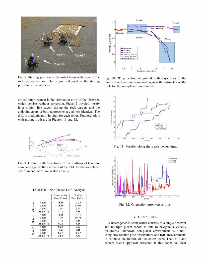
Fig. 8: Starting position of the robot team with view of therock garden section. The origin is defined as the startingposition of the observer.
critical improvement is the orientation error of the observer,which persists without correction. Picket-2 traveled mostlyin a straight line except during the rock garden, and theendpoint errors of both approaches are almost identical. Thedrift is predominantly in pitch for each robot. Temporal plotswith ground truth are in Figures 11 and 12.
Fig. 9: Ground truth trajectories of the multi-robot team arecompared against the estimates of the EKF for the non-planarenvironment. Axes are scaled equally
.
TABLE III: Non-Planar Drift Analysis
Camera-only FusionTwo Pickets Two Pickets
Obs
erve
r x (cm) -4.03 -5.35y (cm) 13.36 12.67z (cm) 1.01 0.04
Angle () 3.12 2.18
Pick
et-1 x (cm) -2.11 -4.48
y (cm) 17.9 16.76z (cm) 1.72 0.10
Angle () 6.22 4.29
Pick
et-2 x (cm) 0.28 0.32
y (cm) -0.20 0.15z (cm) 5.37 5.37
Angle () 3.58 3.59
Fig. 10: 2D projection of ground truth trajectories of themulti-robot team are compared against the estimates of theEKF for the non-planar environment.
Fig. 11: Position along the x-axis versus time.
Fig. 12: Orientation error versus time.
V. CONCLUSION
A heterogeneous team which consists of a single observerand multiple picket robots is able to navigate a visuallyfeatureless, unknown, non-planar environment as a unit,using only relative pose observations and IMU measurementsto estimate the motion of the entire team. The IMU andcamera fusion approach presented in this paper has clear

advantages over a simpler camera-only approach (Figures4, 5, and 6) and its benefits outweigh the cost of havingasynchronous communication. Although calibration of anIMU adds many complications, it is a natural choice forenvironments in which wheel encoders are unreliable. Acamera-only approach heavily relies on line of sight at alltimes, which is restricting and potentially impractical tomaintain. In addition, motion-model based approaches forEKF propagation allow for the rejection of errant camerapose estimates from faulty LED detections or P3P cor-respondence matching. Most importantly, with a camera-only approach, each inchworm increment has an associatedpositional and rotational drift in 6-DOF. The calibration ofthe IMU allows the fusion based approach of using thestationary robots’ gravity vectors to reduce and bound thepitch and roll drift leading to drift in only 4-DOF.
In the future, we will create exploration strategies forlarger robot teams of more than 10 robots. With this in-creasing number of robots, autonomous control is far moreeffective than manual driving. An advanced control schemethat factors in terrain, obstacles, and collaboration of robotswill be developed for effective exploration in hazardousenvironments.
REFERENCES
[1] R. Grabowski, L. E. Navarro-Serment, C. J. Paredis, and P. K.Khosla, “Heterogeneous teams of modular robots for mapping andexploration,” Autonomous Robots, vol. 8, no. 3, pp. 293–308, 2000.
[2] D. W. Haldane, P. Fankhauser, R. Siegwart, and R. S. Fearing,“Detection of slippery terrain with a heterogeneous team of leggedrobots,” in IEEE Int. Conf. on Robotics and Automation, 2014, pp.4576–4581.
[3] L. E. Navarro-Serment, C. J. Paredis, P. K. Khosla, et al., “A beaconsystem for the localization of distributed robotic teams,” in Int. Conf.on Field and Service Robotics, vol. 6, 1999.
[4] S. Tully, G. Kantor, and H. Choset, “Leap-frog path design for multi-robot cooperative localization,” in Int. Conf. on Field and ServiceRobotics. Springer, 2010, pp. 307–317.
[5] R. Kurazume and S. Hirose, “An experimental study of a cooperativepositioning system,” Autonomous Robots, vol. 8, no. 1, pp. 43–52,2000.
[6] K. E. Wenzel, A. Masselli, and A. Zell, “Visual tracking and follow-ing of a quadrocopter by another quadrocopter,” in 2012 IEEE/RSJInternational Conference on Intelligent Robots and Systems. IEEE,2012, pp. 4993–4998.
[7] T. R. Wanasinghe, G. K. Mann, and R. G. Gosine, “Distributedcollaborative localization for a heterogeneous multi-robot system,” in27th IEEE Canadian Conf. on Electrical and Computer Engineering(CCECE), 2014, pp. 1–6.
[8] ——, “Distributed leader-assistive localization method for a heteroge-neous multirobotic system,” IEEE Transactions on Automation Scienceand Engineering, vol. 12, no. 3, pp. 795–809, 2015.
[9] F. Fabresse, F. Caballero, and A. Ollero, “Decentralized simultaneouslocalization and mapping for multiple aerial vehicles using range-onlysensors,” in IEEE Int. Conf. on Robotics and Automation, 2015, pp.6408–6414.
[10] K. E. Bekris, M. Glick, and L. E. Kavraki, “Evaluation of algorithmsfor bearing-only slam,” in IEEE Int. Conf. on Robotics and Automa-tion, 2006, pp. 1937–1943.
[11] R. Madhavan, K. Fregene, and L. E. Parker, “Distributed heteroge-neous outdoor multi-robot localization,” in IEEE Int. Conf. on Roboticsand Automation, 2002, vol. 1, pp. 374–381.
[12] D. Strelow and S. Singh, “Motion estimation from image and iner-tial measurements,” The International Journal of Robotics Research,vol. 23, no. 12, pp. 1157–1195, 2004.
[13] A. I. Mourikis and S. I. Roumeliotis, “A multi-state constraint Kalmanfilter for vision-aided inertial navigation,” in IEEE Int. Conf. onRobotics and Automation, 2007, pp. 3565–3572.
[14] G. Huang, M. Kaess, and J. J. Leonard, “Towards consistent visual-inertial navigation,” in IEEE Int. Conf. on Robotics and Automation,2014, pp. 4926–4933.
[15] M. Faessler, E. Mueggler, K. Schwabe, and D. Scaramuzza, “Amonocular pose estimation system based on infrared LEDs,” in IEEEInt. Conf. on Robotics and Automation, 2014, pp. 907–913.
[16] A. Breitenmoser, L. Kneip, and R. Siegwart, “A monocular vision-based system for 6D relative robot localization,” in IEEE Int. Conf.on Intelligent Robots and Systems, 2011, pp. 79–85.
[17] A. Ahmad, G. D. Tipaldi, P. Lima, and W. Burgard, “Cooperative robotlocalization and target tracking based on least squares minimization,”in IEEE Int. Conf. on Robotics and Automation, 2013, pp. 5696–5701.
[18] V. Indelman, E. Nelson, N. Michael, and F. Dellaert, “Multi-robot posegraph localization and data association from unknown initial relativeposes via expectation maximization,” in IEEE Int. Conf. on Roboticsand Automation, 2014, pp. 593–600.
[19] S. I. Roumeliotis and G. A. Bekey, “Distributed multirobot localiza-tion,” IEEE Transactions on Robotics and Automation, vol. 18, no. 5,pp. 781–795, 2002.
[20] A. Martinelli, F. Pont, and R. Siegwart, “Multi-robot localization usingrelative observations,” in IEEE Int. Conf. on Robotics and Automation,2005, pp. 2797–2802.
[21] A. Howard, “Multi-robot simultaneous localization and mapping usingparticle filters,” The International Journal of Robotics Research,vol. 25, no. 12, pp. 1243–1256, 2006.
[22] L. Carlone, M. K. Ng, J. Du, B. Bona, and M. Indri, “Rao-Blackwellized particle filters multi robot SLAM with unknown initialcorrespondences and limited communication,” in IEEE Int. Conf. onRobotics and Automation, 2010, pp. 243–249.
[23] A. Prorok, A. Bahr, and A. Martinoli, “Low-cost collaborative local-ization for large-scale multi-robot systems,” in IEEE Int. Conf. onRobotics and Automation, 2012, pp. 4236–4241.
[24] L. Quan and Z. Lan, “Linear n-point camera pose determination,”IEEE Transactions on Pattern Analysis and Machine Intelligence,vol. 21, no. 8, pp. 774–780, 1999.
[25] L. Kneip, D. Scaramuzza, and R. Siegwart, “A novel parametrizationof the perspective-three-point problem for a direct computation ofabsolute camera position and orientation,” in IEEE Conf. on ComputerVision and Pattern Recognition (CVPR), 2011, pp. 2969–2976.