Embed Size (px)
Citation preview
1
Abstract—This study deals with cooperative control of
drive motor and clutches for the gear shift of a parallel
hybrid electric vehicle (HEV) with dual-clutch transmission
(DCT). A HEV with DCT powertrain requires sophisticated
control of two clutch actuators and power sources to achieve
outstanding gear shift performances. In this work, a new
shift control strategy based on the feedback of both speed
and torque states is implemented to improve the shift
quality. Differently from previous approaches, the
proposed control uses the dynamic torque observer to
accurately track the desired transient torque during the
inertia phase. Since a drive motor is installed in the HEV’s
driveline, the transient torque through the driveline can be
effectively controlled by using the fast dynamic
characteristics of the drive motor. A major difficulty arising
from the shift control of DCT is the interactions between the
speed and torque control loops. To treat the coupling effects
effectively even in the presence of model uncertainties and
disturbances, a robust multivariable control scheme using
H-infinity loop shaping is suggested especially for the
inertia phase control. The performance of the final
observer-based controller is demonstrated through real
time experiments. Comparative study with the conventional
control approach is also conducted, and detailed discussions
of the results are provided.
Index Terms—Dual-clutch transmission, Hybrid electric vehicle,
Gear shift control, Robust multivariable control, Torque control
NOMENCLATURE
oc Torsional damping coefficient of output shaft.
1ti Gear ratio of input and transfer shaft 1.
2ti Gear ratio of input and transfer shaft 2.
1fi Final reduction gear ratio 1.
2fi Final reduction gear ratio 2.
inJ Equivalent inertia of power sources.
S. Kim is with Hyundai Motor Company, Hwasung 18280, South Korea (e-mail:
[email protected]). S. B. Choi is with the Department of mechanical
engineering, KAIST, Daejeon 34141, South Korea (e-mail: [email protected]).
2,ct eqJ Equivalent inertia of transmission part seen from
output shaft.
vJ Vehicle inertia.
ok Torsional stiffness of output shaft.
1cT Clutch 1 torque.
2cT Clutch 2 torque.
inT Torque from power sources.
oT Output shaft torque.
vT Vehicle resistance torque.
1c Clutch 1 speed (input shaft 1 speed).
2c Clutch 2 speed (input shaft 2 speed).
in Speed of power sources (for parallel mode operation).
w Wheel speed.
I. INTRODUCTION
YBRID electric vehicles (HEVs) provide lower emissions
and better fuel economy than conventional engine-driven
vehicles by effectively using dual energy sources, a fuel and
electrical energy. Managing the power distribution between the
two sources and determining the optimal gear ratio in any
driving conditions are crucial to improve the performance of
HEVs. The typical objective of such power management
control strategies is to minimize fuel consumption while
satisfying the driver’s power demand and other constraints such
as emissions, drivability, and regulation of state of charge.
Previously, various power management strategies were
proposed to optimize fuel economy and emissions of HEVs in
different configurations [1-7].
The power management control provides set-points for
individual servo control loops that operate at a much higher
frequency. In order to attain the optimized HEV performance
designed by the power management strategy, each servo control
loop should reliably achieve the corresponding set-point.
Among the servo control loops, control of the transmission
system is, in particular, important to perform the actual gear
Cooperative Control of Drive Motor and Clutch
for Gear Shift of Hybrid Electric Vehicles with
Dual-clutch Transmission
Sooyoung Kim and Seibum B. Choi, Member, IEEE
H
2
Fig. 1. Configuration of a parallel HEV
shifting for the optimal gear ratio commanded by the power
management control loop. In order to attain the best fuel
economy during gear shifting, the shift transient time should be
minimized so that the optimal gear ratio is achieved as swiftly
as possible. However, if the gear shift is performed too quickly,
large torque oscillations may occur through the driveline.
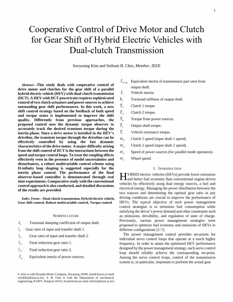
The study deals with gear shift control of a parallel-type HEV
equipped with a dry dual-clutch transmission (DCT), whose
structure is schematically illustrated in Fig. 1. The integrated
starter generator (ISG) is connected to the engine via a belt, and
is used for engine start. The engine clutch installed between the
engine and the drive motor begins to be engaged when the mode
transition from pure electric vehicle mode to parallel hybrid
mode is required. DCTs use two sets of clutches and transfer
shafts during gear shifts to transmit the torque delivered by
power sources to the wheel without using torque converters,
which can effectively overcome the drawbacks of other types
of transmissions. Recently, recognizing its merits, DCT has
been applied not only to production HEVs but also to pure
electric vehicles [8-11]. However, since there is no smoothing
effect of torque converters, DCT powertrains are likely to cause
an awkward shift shock during gear shifting, especially when
the shifting is performed quickly [12, 13]. Fast gear shifting is
generally required to achieve good fuel economy and minimize
vehicle acceleration losses, regardless of the type of
transmission. In addition, if the driver wants fast acceleration
by pressing the accelerator pedal suddenly, the shift time must
be shortened accordingly [14]. Smooth and fast shifting
conditions are in conflict with each other and are generally
regarded as two main goals of shift control [15]. A practical
gear shift control strategy should be designed for real vehicle
applications, upon consideration of such conflicts among
different shift quality criteria.
In general, a gear shift control to achieve the desired gear
ratio commanded by the power management strategy consists
of two levels: upper-level control that calculates the reference
torque values of power sources and clutches satisfying the
desired shifting performances, and lower-level control that
manages the strategies for each actuator to track the reference
torque trajectories. For good control performances, both control
loops should be designed together carefully. In [16], the authors
proposed a dual-loop self-learning fuzzy controller for the gear
engagement control, and experimentally validated the
excellence of the developed dual-loop control structure. In
specific, the upper-level control deals with the desired shift
performance reflected by the driver’s accelerator pedal position
in the vehicle level; that is, the shift should be performed as fast
as the driver wants, and the shift shock should be minimized for
driving comfort. In order to achieve these requirements,
numerous previous studies have proposed various speed
feedback control strategies for the clutch engagement during
gear shift [17-19]. Speed-based control has the advantage that
no additional sensors are required for production vehicles, and
is very effective especially for ATs where damping
characteristics of the torque converter exist. However, DCTs
require more elaborate control of clutches and power sources
focusing on shift shock minimization, although the clutch-to-
clutch shifting process is analogous to that of ATs [14, 19]. For
sophisticated control of DCT, integrated torque and speed
controllers for DCTs were proposed in [15, 20-22]. The authors
made use of calculated static torque values based on the
driveline model equations to deal with the absence of torque
sensors. In [23-25], various methods were proposed to estimate
the transient torque through DCT drivelines more accurately,
but how to actually use them in real-time gear shift controls has
not been dealt with.
In this work, an output shaft torque based shift control
strategy is proposed to improve the gear shift performance of a
parallel HEV with DCT. Differently from previous studies, this
work tries to achieve the desired shift performance through
simultaneous tracking control of dynamic output torque and
speed states during the shift transient. Also, since the drive
motor provides more accurate and faster torque control
compared with the engine, the motor will be mainly utilized for
the gear shift control. Here, the output shaft torque and the slip
speed of the on-coming clutch are selected as the outputs to be
controlled by the three actuators: the off-going clutch, the on-
coming clutch, and the power source (drive motor). The gear
shift control problem is then interpreted as the tracking control
problem of the speed and the torque states in the vehicle
driveline. Another important issue arising in the shift control is
the strong interactions between the speed control loop and
torque control loop. Hence, a robust multivariable controller is
designed as the upper-level control to treat the coupling effects
effectively, in spite of the presence of model uncertainties and
disturbances. The lower-level torque tracking controller for
individual clutch actuators is also implemented to be
coordinated with the upper-level controller, considering the
actuator dynamics.
This paper is organized as follows. In Section II, a driveline
model for a parallel HEV with dry DCT is introduced, and the
design procedure of the driveline torque observer is presented.
The torque observer will be used for the shift control in replace
with torque sensors. In Section III, the detailed design
procedure of the new gear shift controller is described. The
theory and philosophy behind the proposed control strategy are
also explained. In Section IV, the control performance of the
proposed gear shift controller is evaluated through real-time
experiments. Finally, this work is concluded in Section V.
3
II. DRIVELINE MODELING AND TORQUE ESTIMATION
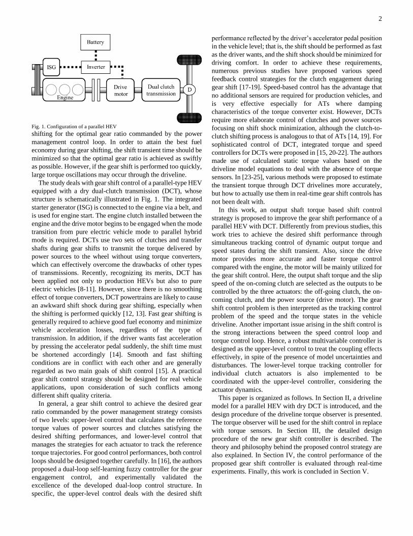
A. Driveline Model
Differently from the conventional engine-driven vehicle, the
parallel HEV dealt with in this work has two additional electric
machines: an ISG and a drive motor [26]. Since this work is
interested in gear shift control of a HEV, we only consider its
parallel mode operations where the engine clutch is engaged
and thus the vehicle is partially or fully driven by the engine.
For detailed information on all the operation modes of a parallel
HEV, see [26, 27]. Then, the driveline structure can be simply
described by the third order dynamics, as illustrated in Fig. 2.
Next, we define slip speed of on-coming clutch (clutch 2),
torsion rate of output shaft, output shaft torque as three states
1 2 3, ,x x x , i.e. 2
1 2 2 3
2 2
, ,c
in c w o
t f
x x x Ti i
= − = − = .
1x stands for the slip speed between the drive motor (or power
sources) and the oncoming clutch (clutch 2). In general, 1x and
3x are considered as control outputs of a gear shifting control
system, since the control performance of those states
determines the shift quality. Then, the dynamics of the HEV
driveline operating in parallel mode is described as follows:
( ) ( )1 2 3 1 2
2,
2 2 2,
2 2 2,
1 1
2,
where
, , , , , ,
10 0
0
1 1 10 0 ,
1 10
1 1
in c c v
ct eq
t f ct eq v v
o
o ov
t f ct eq v
t f
in in ct eq
x x x T T T T
J
i i J J J
c
k c Ji i J J
i i
J J J
= + +
= = =
= − + =
− +
− +
=
x Ax Bu E
x u
Α E
B
2 2
2,
1 1
2 2 2, 2,
1 1
2 2 2, 2,
1
10 .
0
t f
in ct eq
t f
t f ct eq ct eq
o t f o
t f ct eq ct eq
i i
J J
i i
i i J J
c i i c
i i J J
− +
(1)
Here, input torque from power sources inT is defined by the
sum of torques from all the power sources, i.e.
in ISG ISG e dmT i T T T+ + where ISGi is gear ratio between
ISG and engine, and ISGT ,
eT , dmT are torques produced by
ISG, engine, drive motor, respectively.
Fig. 2. Driveline model structure
B. Torque Observer Design
One major difficulty arising in the gear shift control is the
absence of torque sensors in production vehicles, even though
knowledge of torque states of the driveline is essential for the
accurate control. Thus, an observer to concurrently estimate
transient torque through individual clutches and output shaft is
designed in this sub-section.
First, using (1), a linear state observer is developed to
estimate the output shaft torque, as follows:
( ) ( )1 2 3 1 2
11 12
21 22
31 32
ˆ ˆ ˆ
ˆ ˆwhere , , , , , ,ˆ ˆ ˆ ˆ ˆ
1 0 0, , ˆ
0 1 0
TT
in c c vx x x T T T T
L L
L L
L L
= + + +
= = =
= = = −
x Ax Bu E LCx
x u
C L x x x
(2)
Here, L is the observer gain matrix.
The vehicle load torque can be estimated by combining the
net input torque multiplied by gear ratios and the whole vehicle
inertia, as follows:
,,
v t f in v eq wT i i T J = − (3)
where ,t fi i is the current gear ratio and ,v eqJ is the equivalent
vehicle inertia from wheel perspective when one of the clutches
is engaged with the flywheel. It is worth noting that the equation
(3) is valid if one of the clutches is engaged and the other one
is disengaged. Thus, the equation (3) is applicable to general
driving conditions except for the short durations of gear shifts
and vehicle launch. Under the assumption that the vehicle load
does not change during the vehicle launch and each gear shift,
equation (3) is used in the torque observer design.
In fact, torque estimation merely based on (2) may not exhibit
good accuracy because the individual clutch torque values, i.e.
1 2,c cT T cannot be modelled accurately. To resolve the problem,
the equation (4) for modelling torque transmitted through a
clutch during slipping is considered.
,c k c n
T r N F= (4)
where k ,
nF , cr , and N are the kinetic friction coefficient,
and actuator normal force, effective torque radius, and number
of friction surfaces of the clutch. Because the parameters in (4)
such as the kinetic friction coefficient change continuously
with the slip rate of the clutch and environmental factors such
4
as temperature, the clutch torque model is expressed as (5) by
dividing it into known and unknown parts:
( ),,
c k n n c c mT f r N = + (5)
where ,k n ,
nf are nominal values of dynamic friction
coefficient and a constant determining the relation between
clutch normal force n
F and clutch actuator stroke m
. Also, c
is the uncertain part of the parameters that needs to be identified.
The adaptation laws for individual clutch torques are designed
to estimate the clutch torque parameters, as follows [32]:
1 1 1 1
1 1 1 2 1 1 1
2, 2 2 2,
1,ˆ
t f t f
c c c m
in ct eq t f ct eq
i i i iL x x r N
J J i i J
= − + +
(6)
2 2
2 2 1 2 2 2 2
2, 2,
1 1.ˆ
t f
c c c m
in ct eq ct eq
i iL x x r N
J J J
= − + +
(7)
The adaptation laws have a role to correct the parameter
values based on the feedback of the errors between the linear
state observer’s responses and the measured ones, 1 2,x x .
Using the adaptive torque observer (combining (2) with (6) and
(7)), torque values through each clutch and output shaft during
a gear shift can be estimated, and the estimated torque
information will be directly used for implementing the shifting
controller designed in the next section. In fact, even though we
tried to treat parametric uncertainties of clutch using the
adaptive torque observer for practical control purposes in this
paper, the influences of temperature field and slipping speed on
the torque transmissibility should be handled by accurate
modeling of the physical phenomena, ultimately. For more
information, see [28-31].
III. CONTROL STRATEGY DEVELOPMENT
A. Overview
In this section, a novel control strategy is proposed for gear
shifts of a parallel HEV with dry DCT. The control strategy is
developed for the 1-2 upshift, which is difficult to control due
to the large amount of torque transmission. The goal of the DCT
shift control is to perform the clutch-to-clutch shift as fast as the
driver’s intention while satisfying the criteria of shift
smoothness and drivability. A gear shift process of a DCT is
usually discriminated as two phases: torque phase where the
torque handover from the off-going clutch to the on-coming one
occurs and inertia phase where the on-coming clutch with a new
gear ratio is synchronized with the power sources. However, in
this study, we consider the end phase additionally, which comes
immediately after the inertia phase, for more accurate driveline
oscillation control. Specifically, in the case of the HEV, the
drive motor can be used for reducing driveline oscillations
during the end phase. Different control strategies will be
developed for each phase in the following sub-sections.
The proposed control uses the dynamic torque observer to
accurately track the desired transient torque as well as the clutch
slip speed during the inertia phase to attain smooth and fast
shifting. Conventionally, the engine control is limitedly used in
gear shifts due to the slow dynamics of the engine. In the case
of the HEV, by using the fast dynamic characteristics of the
drive motor, one can control the transient torque through the
vehicle driveline more effectively than when using engine
control only. The feasibility of the drive motor control in mode
transition or gear shifts of parallel hybrid cars has been
validated in many studies [9, 27, 33, 34]. In addition, the
regenerative operation of the motor makes the gear shift process
more efficient. A robust multivariable controller is developed
for coordinated control of the drive motor and the on-coming
clutch especially during the inertia phase that dominantly
determines the whole shift quality. The control strategies for
each shift phase are summarized in Table I.
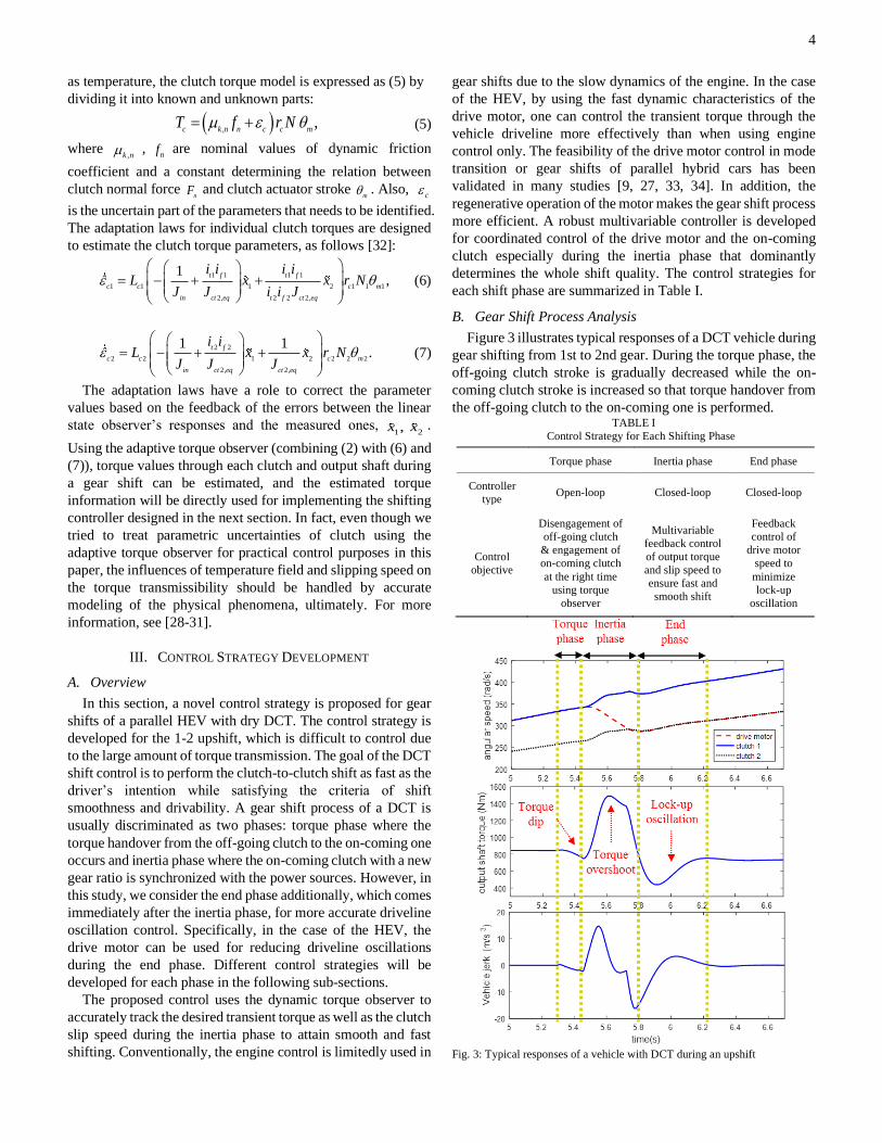
B. Gear Shift Process Analysis
Figure 3 illustrates typical responses of a DCT vehicle during
gear shifting from 1st to 2nd gear. During the torque phase, the
off-going clutch stroke is gradually decreased while the on-
coming clutch stroke is increased so that torque handover from
the off-going clutch to the on-coming one is performed. TABLE I
Control Strategy for Each Shifting Phase
Fig. 3: Typical responses of a vehicle with DCT during an upshift
Torque phase Inertia phase End phase
Controller
type Open-loop Closed-loop Closed-loop
Control objective
Disengagement of
off-going clutch
& engagement of
on-coming clutch
at the right time
using torque
observer
Multivariable
feedback control
of output torque
and slip speed to
ensure fast and
smooth shift
Feedback
control of
drive motor
speed to
minimize
lock-up
oscillation
5
In this phase, the output torque is somewhat reduced due to the
gear ratio change. Note that even if the disengagement of the
off-going clutch and the engagement of the on-coming clutch
are optimally controlled, output torque dip is unavoidable
unless the power source torque is further increased. As soon as
the off-going clutch starts to slip, the inertia phase immediately
begins. During the inertia phase, the speed or power of the
power sources should be reduced to be synchronized with the
input shaft with a new gear ratio. Speed reduction of the engine
and all the components mechanically connected to it such as the
drive motor and ISG causes large overshoot of the output shaft
torque, which deteriorates the shift quality. In the HEVs, the
regenerative operation of the drive motor can be used for the
inertia torque compensation.
As the on-coming clutch is fully engaged with the drive motor,
the end phase begins. The lock-up of the on-coming clutch often
accompanies driveline oscillations. The lock-up oscillations are
primarily caused by the difference between the dynamic torque
of the clutch before the lock-up and its static torque after the
lock-up. As shown in Fig. 3, accurate control of the clutch and
power sources in the inertia phase and end phase is crucial
because relatively large driveline oscillations occur in those
phases compared with the torque phase in which there is not
much variation of speed or torque. Finding a way to reduce the
oscillations that occur after the torque phase without
lengthening the shift time is a key to improving the shift
performance. As mentioned earlier, many previous studies on
the gear shift control have developed speed-based feedback
control strategies. However, control based only on the speed
information cannot guarantee the best shift smoothness,
because the output torque response can be varied according to
input combinations of clutch and power sources while
maintaining the same slip speed response.
C. Torque Phase Control
The objective of torque phase control is to disengage the off-
going clutch and engage the on-coming clutch at the right time
without clutch tie-up and engine flare for good drivability. In
some previously published studies, the off-going clutch was
controlled based on the feedback information of its slip speed
to maintain a small amount of slip speed during the torque phase
(e.g. [14]). However, in this work, an open-loop control strategy
is adopted to avoid the adverse effects of stick-slip vibrations
possibly caused by inappropriate feedback control. Using the
torque information provided by the observer in real time, the
off-going clutch is disengaged at the right time when the torque
transmitted through it becomes zero so that driveline
oscillations and torque interruptions are minimized [35, 36].
D. Inertia Phase Control
At the very beginning of the inertia phase, the off-going
clutch is still slipping and transmits a small part of the torque
delivered by the power sources. However, the amount of the
off-going clutch torque is much less than that of the on-coming
clutch, and thus it can be assumed that the torque transmitted
through the off-going clutch during the inertia phase is
negligible, i.e. 1 0cT .
In the inertia phase, cooperative control of the on-coming
clutch and the power sources is crucial to ensure fast and
smooth clutch engagement with a new gear ratio. The torque
control of power sources is necessary to compensate the large
inertia torque and the driveline oscillations caused by the abrupt
gear ratio change. A robust multivariable feedback controller
based on (1) is designed to concurrently control the output shaft
torque and the slip speed of the on-coming clutch.
From the analysis in sub-section B, it is inferred that the
clutch torque dominantly determines the output torque response
during inertia phase, while both clutch torque and power
sources torque affect the slip speed response. This indicates the
necessity of the simultaneous torque and speed control. In fact,
in the conventional engine-driven vehicles, because the engine
dynamics is much slower than that of the clutch actuator,
decentralized control methods were often used for control and
they cannot consider the strong interactions between the torque
and speed control loops. However, in HEVs, the usage of the
drive motor may increase the whole control performance.
Next, the following three assumptions for the inertia phase
control strategy are used:
A1. ISG is not used during gear shifts, i.e. 0.ISGT =
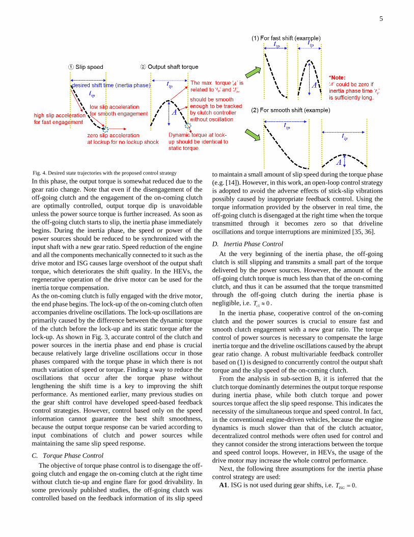
Fig. 4. Desired state trajectories with the proposed control strategy
6
A2. To avoid severe torsional distortion through the driveline,
the torque reduction of the power sources is limited by the
following inequality: 0in ISG ISG e dm e dmT i T T T T T= + + = + .
A3. As long as the motor power is allowed, the demanded
torque reduction for the inertia phase control is only handled by
the drive motor.
The third assumption indicates that in order to improve fuel
efficiency, the regenerative operation of the motor should be
used to compensate for the inertia torque as much as possible
without the aid of engine control. It should be noted that the
torque reduction control of the engine is inevitably required in
addition to the regenerative operation of the drive motor when
a gear shift is initiated at a very high speed range of the motor,
for example, 6000rpm or more.
1) Desired State Trajectories
Since the control states are directly related to the shift quality,
how their reference trajectories are defined is very crucial.
Assuming the input torque from power sources is not changed
substantially before and after the gear shift, the output shaft
torque value right after the lock-up of the on-coming clutch (end
of the gear shift) is accurately calculated using the information
of the input torque and gear ratio values. If the torque phase
control is properly conducted, the initial and end values of the
output torque in inertia phase are the same as the value of the
static torque obtained when engaged with the new gear. It is
necessary to make the desired transient trajectories for the states
between the initial and end values in the inertia phase. Given a
desired shift time determined by the driver’s pedal position, the
desired values of the two control states are shaped to enhance
the shift smoothness as much as possible. First, we designed the
reference shape of the on-coming clutch slip speed such that the
magnitude of its deceleration increases from the initial
deceleration value until the first half of the inertia phase to
reduce the shift time and then decreases until the end of the
inertia phase for good ride quality. Most importantly, at the end
of the inertia phase, the slip acceleration should be zero to
minimize the torque discontinuity between before and after the
lock-up [36]. The final value conditions of the slip speed and its
acceleration are described as (8):
2 , 2 ,( ) ( ) 0,
sl ip f sl ip ft t = = (8)
where ,ip ft is the end time of the inertia phase. Also, the output
shaft torque values should increase until half of the inertia phase
for fast engagement and decrease during the other half to
minimize the lock-up oscillations. Specifically, by defining
, _ 2o s ndT as the static output torque value when the new gear is
engaged after lock-up, the initial and final value conditions for
output shaft torque are described as follows:
, , , _ 2( ) ( ) ,
o ip i o ip f o s ndT t T t T= = (9)
where ,ip it is the initiation time of the inertia phase.
The combination of (8) and (9) can ensure minimization of the
driveline oscillations after the lock-up. The condition (9)
indicates that even though the on-coming clutch stroke is
increased at the beginning of inertia phase, the stroke should be
decreased again to the level of the next static torque at the lock-
up. The desired state trajectories for the states satisfying the
desired shift time and boundary conditions (8) and (9) are
designed in the form of look-up tables. A sinusoidal shape is
adopted to shape the trajectories, which is smooth enough to be
tracked by the lower-level actuator controls. As soon as the
inertia phase flag is switched-on, the desired value generator
operates in real-time to generate the reference values for the
inertia phase control. In accordance with the driver’s pedal
position, the desired shift time and the maximum allowable
value of the output torque (denoted as ‘ A ’ in Fig. 4) are
determined, and the corresponding desired values are given to
the controller. Note that the initial output torque value cannot
be measured, and thus it is obtained from the torque observer
developed in the previous section.
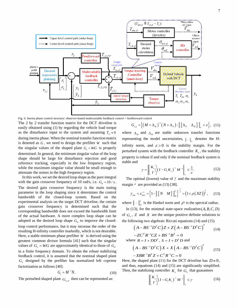
2) Multivariable Feedback Control Law
In this sub-section, a robust multivariable controller as the
upper-level control for the driveline states is designed to track
the desired state values accurately in the presence of the loop
interactions. The upper-level control provides the torque
commands for the drive motor and the on-coming clutch. The
actuator-level controllers (lower-level control) then conduct
torque tracking control to generate the desired torques
considering the actuators’ characteristics. In specific, the drive
motor torque is controlled by the inverter drive through pulse
width modulation method, and the clutch actuator is controlled
using a simple PD position tracking algorithm to generate the
commanded clutch torque.
The robust multivariable controller designed in this paper is
an H-infinity loop shaping controller, which is based on H-
infinity robust stabilization combined with classical loop
shaping [38-40]. The H-infinity loop shaping design procedure
is divided into stages: first, the open-loop transfer function
matrix of the system is augmented by the pre-compensator to
shape its singular values as desired, and second, the shaped
transfer function is robustly stabilized with respect to the plant
uncertainties (in the form of coprime factor uncertainty) based
on H-infinity optimization theory. The main advantage using
this approach is that one can easily tune the control performance
by shaping the open-loop response based on the knowledge of
basic loop shaping. In addition, the H-infinity robust
stabilization does not require time consuming iterations to
obtain its solution, and explicit formulas for the resulting
controller exist, differently from other H-infinity optimization
problems.
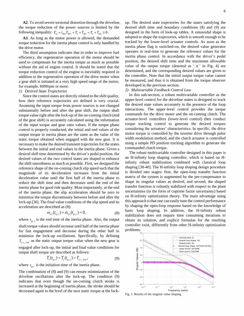
Fig. 5. Results of the singular value shaping
7
The 2 by 2 transfer function matrix for the DCT driveline is
easily obtained using (1) by regarding the vehicle load torque
as the disturbance input to the system and assuming 1 0cT
during inertia phase. When the nominal transfer function matrix
is denoted as G , we need to design the prefilter W such that
the singular values of the shaped plant sG WG= is properly
determined. In general, the minimum singular value of the loop
shape should be large for disturbance rejection and good
reference tracking, especially in the low frequency region,
while the maximum singular value should be small enough to
attenuate the noises in the high frequency region.
In this work, we set the desired loop shape as the pure integral
with the gain crossover frequency of 10 rad/s, i.e. 10 /dG s= .
The desired gain crossover frequency is the main tuning
parameter in the loop shaping since it determines the control
bandwidth of the closed-loop system. Based on the
experimental analysis on the target DCT driveline, the certain
gain crossover frequency is determined such that the
corresponding bandwidth does not exceed the bandwidth limit
of the actual hardware. A more complex loop shape can be
adopted as the desired loop shape dG to improve the closed-
loop control performance, but it may increase the order of the
resulting H-infinity controller markedly, which is not desirable.
Here, a stable minimum phase prefilter W is derived using the
greatest common divisor formula [41] such that the singular
values of sG WG= are approximately identical to those of
dG
in a finite frequency domain. To obtain the robust stabilizing
feedback control, it is assumed that the nominal shaped plant
sG designed by the prefilter has normalized left coprime
factorization as follows [40]: 1 .
sG M N−= (10)
The perturbed shaped plant ,s pG then can be represented as:
( ) ( ) 1
,: ,
s p M N N MG M N
−
= + + (11)
where M and
M are stable unknown transfer functions
representing the model uncertainties,
denotes the H-
infinity norm, and 0 is the stability margin. For the
perturbed system with the feedback controller sK , the stability
property is robust if and only if the nominal feedback system is
stable and
( )1 1 1
.s
s s
KI G K M
I
− −
= −
(12)
The optimal (lowest) value of and the maximum stability
margin are provided as (13) [38].
( )( )1
12 21 2
min max1 1 ,
HN M XZ
−−= = − = + (13)
where 2
H is the Hankel norm and is the spectral radius.
In (13), for the minimal state-space realization ( , , , )A B C D
of sG , Z and X are the unique positive definite solutions to
the following two algebraic Riccati equations (14) and (15).
( ) ( )1 1
1 1 0
TT T
T T
A BS D C Z Z A BS D C
ZC R CZ BS B
− −
− −
− + −
− + =
(14)
where ,T TR I DD S I D D= + = + and
( ) ( )1 1
1 1 0
TT T
T T
A BS D C X X A BS D C
XBR B Z C R C
− −
− −
− + −
− + =
(15)
Here, the shaped plant (11) for the DCT driveline has 0D ,
and thus, equations (14) and (15) are significantly simplified.
Then, the stabilizing controller sK for
sG that guarantees
( )1 1s
s s
KI G K M
I
− −
−
(16)
Fig. 6. Inertia phase control structure: observer-based multivariable feedback control + feedforward control
8
for a specified min is derived using the explicit formula
specified in [39]. The final H-infinity loop shaping controller is
denoted as sK WK= . The singular values of the resulting
closed-loop shape as well as the shaped plant by the prefilter
are exhibited in Fig. 5. From the results of the multivariable
control strategy, the closed-loop system exhibited decoupled
and good tracking responses. The robust stability of the H-
infinity controller will guarantee the desired control
performance even in the presence of unknown disturbances.
3) Feedforward Control Law
In order to improve the transient response of the controller,
one can increase the feedback gain or the gain crossover
frequency of the designed prefilter. However, just increasing
the feedback gain can easily cause undesirable oscillatory
responses according to the driving circumstances. Thus, a
feedforward control law for the clutch 2 input is derived to
improve the torque tracking response, as follows:
( )1
2, 2 2 2, , ,c FFT f r r x−= (17)
where the dynamics of the third state in (1) is denoted as:
( )
2 3 , 2 , 3
2 2 2,
,
2 2 2 3
2,
1 1
1, , ,
o eq o eq
t f ct eq v
o eq
c v c
ct eq v
y x k x c xi i J J
cT T f T x x
J J
= = − +
+ + =
(18)
In equation (18), the vehicle load torque is calculated using (3).
To investigate the effects of the feedforward control on the
whole control responses, several experiments were carried out
for three controller types: feedback control (H-infinity loop
shaping) only, feedforward control only, and a combination of
them. The corresponding results are shown in Fig. 7.
The feedforward only case exhibited a fast response at the
beginning but cannot track the desired value accurately due to
the model uncertainties. Also, the results of the feedback
control showed slow response at the beginning, and exhibited
unwanted oscillatory responses to track the desired values.
However, when using combined control of feedforward and
feedback, the tracking performance was greatly improved since
it took advantage of both the control laws.
Fig. 7. Tracking performance comparison: (1) feedback control only (H-infinity
loop shaping controller), (2) feedforward control only, (3) feedback +
feedforward control (proposed)
The final controller is developed as the observer-based
multivariable controller combined with the feedforward control,
as described in Fig. 6.
E. End Phase Control
In order to treat the driveline oscillations effectively, an
additional damping control law is designed for the end phase.
A feedback control law aimed at reducing the difference of the
transmission input speed (multiplied by gear ratios) and wheel
speed is designed to attenuate the lock-up oscillations. Using
the fast torque response of the drive motor, the driveline
oscillations at the beginning of the end phase can be
significantly improved. During the end phase, the stroke of the
on-coming clutch should be increased further to ensure its lock-
up.
IV. EXPERIMENTS
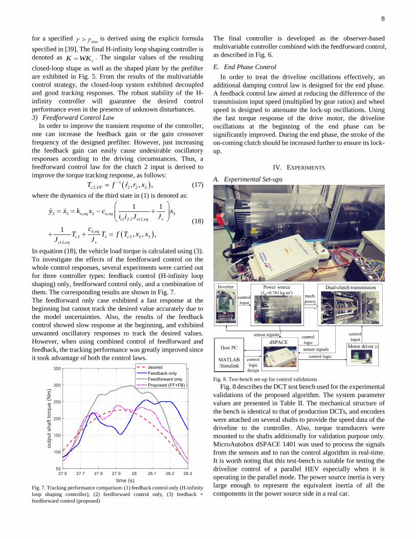
A. Experimental Set-ups
Fig. 8. Test-bench set-up for control validations
Fig. 8 describes the DCT test bench used for the experimental
validations of the proposed algorithm. The system parameter
values are presented in Table II. The mechanical structure of
the bench is identical to that of production DCTs, and encoders
were attached on several shafts to provide the speed data of the
driveline to the controller. Also, torque transducers were
mounted to the shafts additionally for validation purpose only.
MicroAutobox dSPACE 1401 was used to process the signals
from the sensors and to run the control algorithm in real-time.
It is worth noting that this test-bench is suitable for testing the
driveline control of a parallel HEV especially when it is
operating in the parallel mode. The power source inertia is very
large enough to represent the equivalent inertia of all the
components in the power source side in a real car.
9
(a)
(b)
(c)
(d)
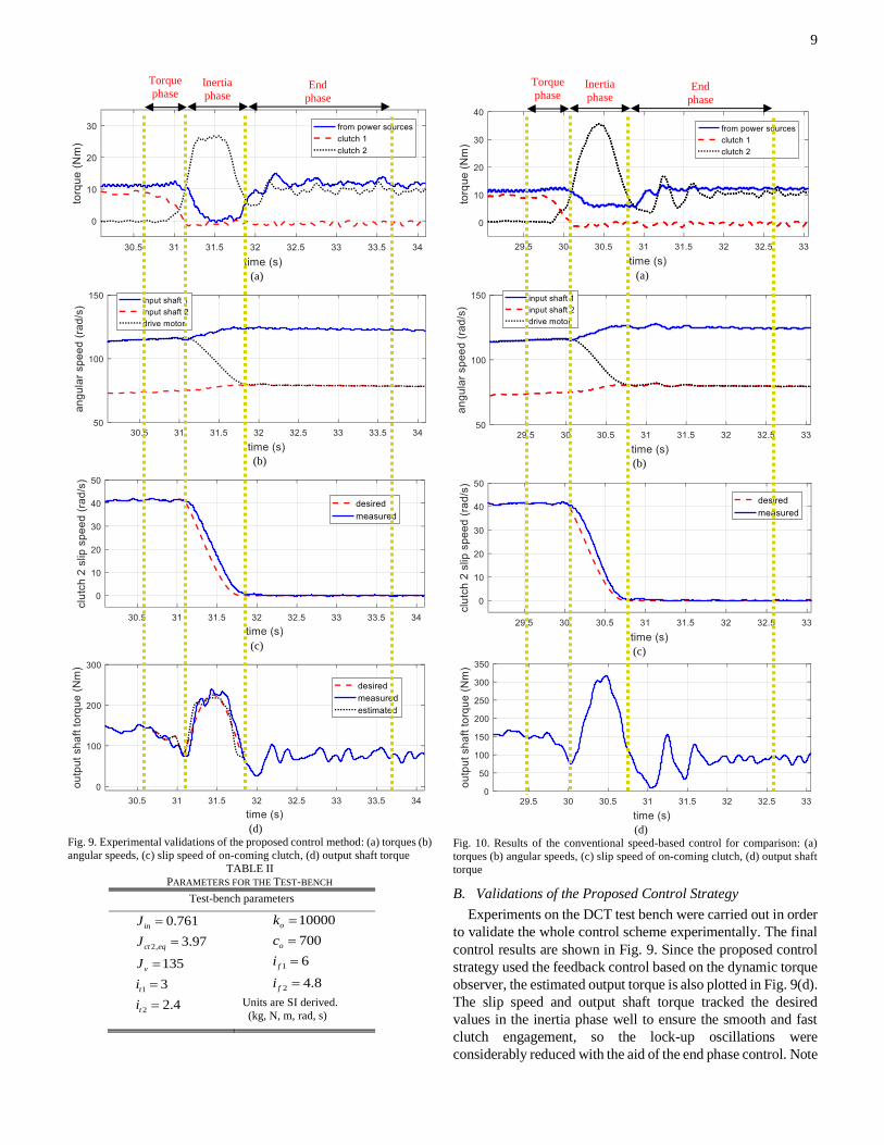
Fig. 9. Experimental validations of the proposed control method: (a) torques (b)
angular speeds, (c) slip speed of on-coming clutch, (d) output shaft torque
TABLE II
PARAMETERS FOR THE TEST-BENCH
Test-bench parameters
2,
1
2
0.761
3.97
135
3
2.4
in
ct eq
v
t
t
J
J
J
i
i
=
=
=
=
=
1
2
10000
700
6
4.8
o
o
f
f
k
c
i
i
=
=
=
=
Units are SI derived.
(kg, N, m, rad, s)
(a)
(b)
(c)
(d)
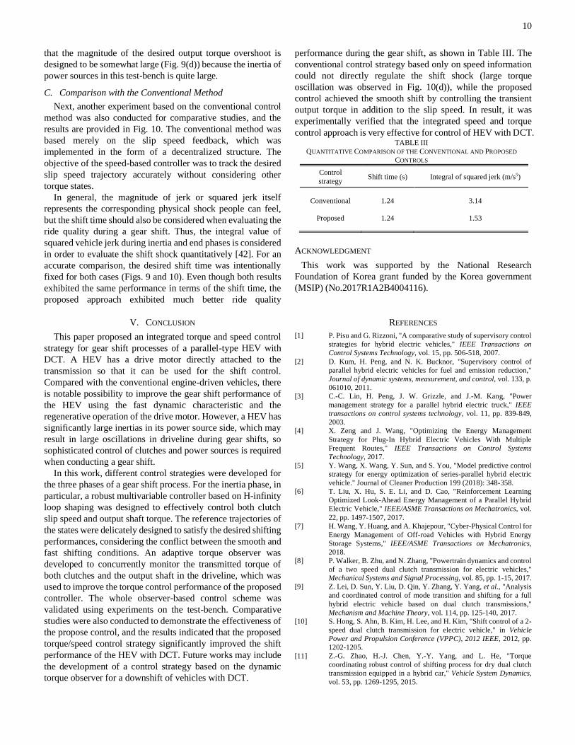
Fig. 10. Results of the conventional speed-based control for comparison: (a)
torques (b) angular speeds, (c) slip speed of on-coming clutch, (d) output shaft
torque
B. Validations of the Proposed Control Strategy
Experiments on the DCT test bench were carried out in order
to validate the whole control scheme experimentally. The final
control results are shown in Fig. 9. Since the proposed control
strategy used the feedback control based on the dynamic torque
observer, the estimated output torque is also plotted in Fig. 9(d).
The slip speed and output shaft torque tracked the desired
values in the inertia phase well to ensure the smooth and fast
clutch engagement, so the lock-up oscillations were
considerably reduced with the aid of the end phase control. Note
Inertia phase
Torque phase
End phase
Inertia phase
Torque phase
End phase
10
that the magnitude of the desired output torque overshoot is
designed to be somewhat large (Fig. 9(d)) because the inertia of
power sources in this test-bench is quite large.
C. Comparison with the Conventional Method
Next, another experiment based on the conventional control
method was also conducted for comparative studies, and the
results are provided in Fig. 10. The conventional method was
based merely on the slip speed feedback, which was
implemented in the form of a decentralized structure. The
objective of the speed-based controller was to track the desired
slip speed trajectory accurately without considering other
torque states.
In general, the magnitude of jerk or squared jerk itself
represents the corresponding physical shock people can feel,
but the shift time should also be considered when evaluating the
ride quality during a gear shift. Thus, the integral value of
squared vehicle jerk during inertia and end phases is considered
in order to evaluate the shift shock quantitatively [42]. For an
accurate comparison, the desired shift time was intentionally
fixed for both cases (Figs. 9 and 10). Even though both results
exhibited the same performance in terms of the shift time, the
proposed approach exhibited much better ride quality
performance during the gear shift, as shown in Table III. The
conventional control strategy based only on speed information
could not directly regulate the shift shock (large torque
oscillation was observed in Fig. 10(d)), while the proposed
control achieved the smooth shift by controlling the transient
output torque in addition to the slip speed. In result, it was
experimentally verified that the integrated speed and torque
control approach is very effective for control of HEV with DCT.
ACKNOWLEDGMENT
This work was supported by the National Research
Foundation of Korea grant funded by the Korea government
(MSIP) (No.2017R1A2B4004116).
V. CONCLUSION
This paper proposed an integrated torque and speed control
strategy for gear shift processes of a parallel-type HEV with
DCT. A HEV has a drive motor directly attached to the
transmission so that it can be used for the shift control.
Compared with the conventional engine-driven vehicles, there
is notable possibility to improve the gear shift performance of
the HEV using the fast dynamic characteristic and the
regenerative operation of the drive motor. However, a HEV has
significantly large inertias in its power source side, which may
result in large oscillations in driveline during gear shifts, so
sophisticated control of clutches and power sources is required
when conducting a gear shift.
In this work, different control strategies were developed for
the three phases of a gear shift process. For the inertia phase, in
particular, a robust multivariable controller based on H-infinity
loop shaping was designed to effectively control both clutch
slip speed and output shaft torque. The reference trajectories of
the states were delicately designed to satisfy the desired shifting
performances, considering the conflict between the smooth and
fast shifting conditions. An adaptive torque observer was
developed to concurrently monitor the transmitted torque of
both clutches and the output shaft in the driveline, which was
used to improve the torque control performance of the proposed
controller. The whole observer-based control scheme was
validated using experiments on the test-bench. Comparative
studies were also conducted to demonstrate the effectiveness of
the propose control, and the results indicated that the proposed
torque/speed control strategy significantly improved the shift
performance of the HEV with DCT. Future works may include
the development of a control strategy based on the dynamic
torque observer for a downshift of vehicles with DCT.
REFERENCES
[1] P. Pisu and G. Rizzoni, "A comparative study of supervisory control
strategies for hybrid electric vehicles," IEEE Transactions on
Control Systems Technology, vol. 15, pp. 506-518, 2007.
[2] D. Kum, H. Peng, and N. K. Bucknor, "Supervisory control of
parallel hybrid electric vehicles for fuel and emission reduction,"
Journal of dynamic systems, measurement, and control, vol. 133, p.
061010, 2011.
[3] C.-C. Lin, H. Peng, J. W. Grizzle, and J.-M. Kang, "Power
management strategy for a parallel hybrid electric truck," IEEE
transactions on control systems technology, vol. 11, pp. 839-849,
2003.
[4] X. Zeng and J. Wang, "Optimizing the Energy Management
Strategy for Plug-In Hybrid Electric Vehicles With Multiple
Frequent Routes," IEEE Transactions on Control Systems
Technology, 2017.
[5] Y. Wang, X. Wang, Y. Sun, and S. You, "Model predictive control
strategy for energy optimization of series-parallel hybrid electric
vehicle." Journal of Cleaner Production 199 (2018): 348-358.
[6] T. Liu, X. Hu, S. E. Li, and D. Cao, "Reinforcement Learning
Optimized Look-Ahead Energy Management of a Parallel Hybrid
Electric Vehicle," IEEE/ASME Transactions on Mechatronics, vol.
22, pp. 1497-1507, 2017.
[7] H. Wang, Y. Huang, and A. Khajepour, "Cyber-Physical Control for
Energy Management of Off-road Vehicles with Hybrid Energy
Storage Systems," IEEE/ASME Transactions on Mechatronics,
2018.
[8] P. Walker, B. Zhu, and N. Zhang, "Powertrain dynamics and control
of a two speed dual clutch transmission for electric vehicles,"
Mechanical Systems and Signal Processing, vol. 85, pp. 1-15, 2017.
[9] Z. Lei, D. Sun, Y. Liu, D. Qin, Y. Zhang, Y. Yang, et al., "Analysis
and coordinated control of mode transition and shifting for a full
hybrid electric vehicle based on dual clutch transmissions,"
Mechanism and Machine Theory, vol. 114, pp. 125-140, 2017.
[10] S. Hong, S. Ahn, B. Kim, H. Lee, and H. Kim, "Shift control of a 2-
speed dual clutch transmission for electric vehicle," in Vehicle
Power and Propulsion Conference (VPPC), 2012 IEEE, 2012, pp.
1202-1205.
[11] Z.-G. Zhao, H.-J. Chen, Y.-Y. Yang, and L. He, "Torque
coordinating robust control of shifting process for dry dual clutch
transmission equipped in a hybrid car," Vehicle System Dynamics,
vol. 53, pp. 1269-1295, 2015.
TABLE III
QUANTITATIVE COMPARISON OF THE CONVENTIONAL AND PROPOSED
CONTROLS
Control
strategy Shift time (s) Integral of squared jerk (m/s5)
Conventional
1.24
3.14
Proposed
1.24
1.53
11
[12] E. Galvagno, M. Velardocchia, and A. Vigliani, "Dynamic and
kinematic model of a dual clutch transmission," Mechanism and
Machine Theory, vol. 46, pp. 794-805, 2011.
[13] J. Kim, S. B. Choi, and J. J. Oh, "Adaptive Engagement Control of
a Self-Energizing Clutch Actuator System Based on Robust Position
Tracking," IEEE/ASME Transactions on Mechatronics, vol. 23, pp.
800-810, 2018.
[14] Y. Liu, D. Qin, H. Jiang, and Y. Zhang, "Shift control strategy and
experimental validation for dry dual clutch transmissions,"
Mechanism and Machine Theory, vol. 75, pp. 41-53, 2014.
[15] K. van Berkel, T. Hofman, A. Serrarens, and M. Steinbuch, "Fast
and smooth clutch engagement control for dual-clutch
transmissions," Control Engineering Practice, vol. 22, pp. 57-68,
2014.
[16] X. Wang, L. Li, K. He, C. Liu, " Dual-Loop Self-Learning Fuzzy
Control for AMT Gear Engagement: Design and Experiment," IEEE
Transactions on Fuzzy Systems, Vol. 26, pp.1813-1822, 2017.
[17] B. Z. Gao, H. Chen, K. Sanada, and Y. Hu, "Design of clutch-slip
controller for automatic transmission using backstepping,"
Mechatronics, IEEE/ASME Transactions on, vol. 16, pp. 498-508,
2011.
[18] F. Meng, G. Tao, T. Zhang, Y. Hu, and P. Geng, "Optimal shifting
control strategy in inertia phase of an automatic transmission for
automotive applications," Mechanical Systems and Signal
Processing, vol. 60, pp. 742-752, 2015.
[19] F. Liu, L. Chen, D. Li, and C. Yin, "Improved clutch slip control for
automated transmissions," Proceedings of the Institution of
Mechanical Engineers, Part C: Journal of Mechanical Engineering
Science, p. 0954406217734578, 2017.
[20] P. D. Walker, N. Zhang, and R. Tamba, "Control of gear shifts in
dual clutch transmission powertrains," Mechanical Systems and
Signal Processing, vol. 25, pp. 1923-1936, 2011.
[21] M. Goetz, M. Levesley, and D. Crolla, "Dynamics and control of
gearshifts on twin-clutch transmissions," Proceedings of the
institution of mechanical engineers, Part D: Journal of Automobile
Engineering, vol. 219, pp. 951-963, 2005.
[22] S. Kim, J. Oh, and S. Choi, "Gear shift control of a dual-clutch
transmission using optimal control allocation," Mechanism and
Machine Theory, vol. 113, pp. 109-125, 2017.
[23] S. Kim, J. J. Oh, and S. B. Choi, "Driveline Torque Estimations for
a Ground Vehicle with Dual-clutch Transmission," IEEE
Transactions on Vehicular Technology, vol. 67, pp. 1977-1989,
2018.
[24] Z. Zhao, L. He, Y. Yang, C. Wu, X. Li, and J. K. Hedrick,
"Estimation of torque transmitted by clutch during shifting process
for dry dual clutch transmission," Mechanical Systems and Signal
Processing, vol. 75, pp. 413-433, 2016.
[25] Z. Zhao, X. Li, L. He, C. Wu, and J. K. Hedrick, "Estimation of
Torques Transmitted by Twin-clutch of Dry Dual Clutch
Transmission during Vehicle’s Launching Process," IEEE
Transactions on Vehicular Technology, 2016.
[26] J. Oh, S. Choi, Y. Chang, and J. Eo, "Engine clutch torque
estimation for parallel-type hybrid electric vehicles," International
Journal of Automotive Technology, vol. 18, pp. 125-135, 2017.
[27] M. Song, J. Oh, S. Choi, Y. Kim, and H. Kim, "Motor control of a
parallel hybrid electric vehicle during mode change without an
integrated starter generator," Journal of Electrical Engineering &
Technology (JEET), vol. 8, pp. 930-937, 2013.
[28] A. Myklebust and L. Eriksson, "Modeling, observability, and
estimation of thermal effects and aging on transmitted torque in a
heavy duty truck with a dry clutch," IEEE/ASME transactions on
mechatronics, vol. 20, pp. 61-72, 2015.
[29] M. Pisaturo, A. Senatore, "Simulation of engagement control in
automotive dry-clutch and temperature field analysis through finite
element model," Applied Thermal Engineering, vol. 93, pp.958-966,
2016.
[30] M. Pisaturo, A. Senatore, and V. D'Agostino, "Automotive dry-
clutch control: Engagement tracking and FE thermal model,"
Proceedings of IEEE 20th Jubilee International Conference on
Intelligent Engineering Systems, 2016.
[31] A. D. Gatta, L. Iannelli, M. Pisaturo, A. Senatore and F. Vasca, "A
Dry Clutch Engagement Controller with Thermal Effects
Compensation," Proceedings of 2018 IEEE Conference on Control
Technology and Applications, Copenhagen, pp. 1228-1233, 2018.
[32] S. Kim and S. Choi, "Control-oriented modeling and torque
estimations for vehicle driveline with dual-clutch transmission,"
Mechanism and Machine Theory, vol. 121, pp. 633-649, 2018.
[33] Z. Zhao, D. Lei, J. Chen, and H. Li, "Optimal control of mode
transition for four-wheel-drive hybrid electric vehicle with dry dual-
clutch transmission," Mechanical Systems and Signal Processing,
vol. 105, pp. 68-89, 2018.
[34] V. Ranogajec and J. Deur, "Bond graph analysis and optimal control
of the hybrid dual clutch transmission shift process," Proceedings of
the Institution of Mechanical Engineers, Part K: Journal of Multi-
body Dynamics, vol. 231, pp. 480-492, 2017.
[35] B. Gao, H. Chen, J. Li, L. Tian, and K. Sanada, "Observer-based
feedback control during torque phase of clutch-to-clutch shift
process," International Journal of Vehicle Design, vol. 58, pp. 93-
108, 2012.
[36] M. Pettersson and L. Nielsen, "Gear shifting by engine control,"
IEEE Transactions on Control Systems Technology, vol. 8, pp. 495-
507, 2000.
[37] F. Garofalo, L. Glielmo, L. Iannelli, and F. Vasca, "Smooth
engagement for automotive dry clutch," in Decision and Control,
2001. Proceedings of the 40th IEEE Conference on, 2001, pp. 529-
534.
[38] D. McFarlane and K. Glover, "A loop-shaping design procedure
using H/sub infinity/synthesis," IEEE transactions on automatic
control, vol. 37, pp. 759-769, 1992.
[39] K. Glover and D. McFarlane, "Robust stabilization of normalized
coprime factor plant descriptions with H/sub infinity/-bounded
uncertainty," IEEE transactions on automatic control, vol. 34, pp.
821-830, 1989.
[40] S. Skogestad and I. Postlethwaite, Multivariable feedback control:
analysis and design vol. 2: Wiley New York, 2007.
[41] V. Le and M. Safonov, "Rational matrix GCDs and the design of
squaring-down compensators-a state-space theory," IEEE
Transactions on Automatic Control, vol. 37, pp. 384-392, 1992.
[42] J. Levinson, J. Askeland, J. Becker, J. Dolson, D. Held, S. Kammel,
et al., "Towards fully autonomous driving: Systems and
algorithms," in Intelligent Vehicles Symposium (IV), 2011 IEEE,
2011, pp. 163-168.
Sooyoung Kim received his B.S. and M.S.
degrees, and Ph.D. in mechanical
engineering from KAIST, Daejeon, Korea.
He is currently a Senior Research Engineer with Hyundai Motor Company,
Hwasung, South Korea. His current
research interests include model-based
control and state estimation of powertrains
for mass-produced vehicles.
Seibum B. Choi (M’09) received his B.S.
in mechanical engineering from Seoul
National University, Seoul, Korea, his
M.S. in mechanical engineering from KAIST, Daejeon, Korea, and his Ph.D. in
control from the University of California,
Berkeley, CA, USA, in 1993.
From 1993 to 1997, he was involved in
the development of automated vehicle
control systems at the Institute of Transportation Studies,
University of California. Through 2006, he was with TRW,
Livonia, MI, USA, where he was involved in the development of advanced vehicle control systems. Since 2006, he has been
faculty in the Mechanical Engineering Department, KAIST,
Korea. His current research interests include fuel-saving
technology, vehicle dynamics and control, and active safety
systems.
Prof. Choi is a Member of the American Society of
Mechanical Engineers, the Society of Automotive Engineers,
and the Korean Society of Automotive Engineers.