Embed Size (px)
DESCRIPTION
manual
Citation preview
CEAG Notlichtsysteme GmbH2
Assembly and Operating Instructions Central Battery System ZB-S with STAR-Technology
1. General Information
1.1 Description of Symbols . . . . . . . . . . . . . . . . . . . . . . . 5
1.2 Information regarding these Instructions . . . . . . . . . . . . . . . . . . . 5
1.3 Further Applicable Documents . . . . . . . . . . . . . . . . . . . . . 5
1.4 Liability and Guarantee . . . . . . . . . . . . . . . . . . . . . . . 5
1.5 Copyright Protection . . . . . . . . . . . . . . . . . . . . . . . . 6
1.6 Spare Parts . . . . . . . . . . . . . . . . . . . . . . . . . . 6
1.7 Recycling . . . . . . . . . . . . . . . . . . . . . . . . . . . 6
2. Safety
2.1 Inteded Use . . . . . . . . . . . . . . . . . . . . . . . . . . 6
2.2 Contents of Operating Instructions . . . . . . . . . . . . . . . . . . . . 7
2.3 Changes and Modifications to the System . . . . . . . . . . . . . . . . . . 7
2.4 Responsibility of the Operator . . . . . . . . . . . . . . . . . . . . . 7
2.5 Personnel Requirements . . . . . . . . . . . . . . . . . . . . . . . 7
2.6 Operational Safety . . . . . . . . . . . . . . . . . . . . . . . . 7
2.7 Personal Protective Equipment . . . . . . . . . . . . . . . . . . . . . 7
3. Technical Data
3.1 Data Sheet for ZB-S/26 . . . . . . . . . . . . . . . . . . . . . . . 8
3.2 Data Sheet for ZB-S/18 . . . . . . . . . . . . . . . . . . . . . . . 9
3.3 Data Sheet for ZB-S/LAD . . . . . . . . . . . . . . . . . . . . . . 10
3.4 Data Sheet for ZB-S/10C . . . . . . . . . . . . . . . . . . . . . . . 11
3.5 Data Sheet for ZB-S/10C6 . . . . . . . . . . . . . . . . . . . . . . 12
3.6 Data Sheet for ZB-S/18C6 . . . . . . . . . . . . . . . . . . . . . . 13
3.7 Data Sheet for ZB-S/26C6 . . . . . . . . . . . . . . . . . . . . . . 14
3.8 Data Sheet for ZB-S/18C3 . . . . . . . . . . . . . . . . . . . . . . 15
3.9 Data Sheet for ZB-S/10C3 . . . . . . . . . . . . . . . . . . . . . . 16
3.10 Data Sheet for ZB-S/2C3 . . . . . . . . . . . . . . . . . . . . . . . 17
3.11 Data Sheet for US-S/36 . . . . . . . . . . . . . . . . . . . . . . . 18
3.12 Data Sheet for US-S/28 . . . . . . . . . . . . . . . . . . . . . . . 19
3.13 Data Sheet for US-S/21 . . . . . . . . . . . . . . . . . . . . . . . 20
3.14 Data Sheet for US-S/13 . . . . . . . . . . . . . . . . . . . . . . . 21
3.15 Data Sheet for US-S/5 . . . . . . . . . . . . . . . . . . . . . . . 22
3.16 Data Sheet for ESF-E30/13S . . . . . . . . . . . . . . . . . . . . . . 23
3.17 Data Sheet for ESF-E30/13S-P . . . . . . . . . . . . . . . . . . . . . 24
3.18 Data Sheet for ESF-E30/28S . . . . . . . . . . . . . . . . . . . . . . 25
3.19 Data Sheet for ESF-E30/28S-P . . . . . . . . . . . . . . . . . . . . . 26
4. Construction and Function
4.1 Example of Control Cabinet-Construction (ZB-S/26) . . . . . . . . . . . . . . . 28
4.2 Product Description . . . . . . . . . . . . . . . . . . . . . . . . 29
4.3 Operation Modes . . . . . . . . . . . . . . . . . . . . . . . . . 29
4.4 Overview over the Components . . . . . . . . . . . . . . . . . . . . . 30
4.4.1 Control Module ZB-S . . . . . . . . . . . . . . . . . . . . . . . . 30
4.4.2 DC/DC Converter.2 . . . . . . . . . . . . . . . . . . . . . . . . 34
4.4.2.1 AC-Module . . . . . . . . . . . . . . . . . . . . . . . . . . 34
4.4.3 Charging Module LT.1 2,5 . . . . . . . . . . . . . . . . . . . . . . 34
PART 1
Index
CEAG Notlichtsysteme GmbH3
Assembly and Operating Instructions Central Battery System ZB-S with STAR-Technology
4.4.4 Circuit change-over modules overview (SKU´s) . . . . . . . . . . . . . . . . . 36
4.4.5 Inverter SWR 150 . . . . . . . . . . . . . . . . . . . . . . . . . 40
4.4.5.1 Determination of current consumption value from the battery . . . . . . . . . . . . . 44
4.4.6 Event printer PD3 . . . . . . . . . . . . . . . . . . . . . . . . . 46
4.4.7 Relay module CG IV and CG V . . . . . . . . . . . . . . . . . . . . . 47
4.4.8 F3 remote indication . . . . . . . . . . . . . . . . . . . . . . . . 48
4.4.9 External TLS-bus-module . . . . . . . . . . . . . . . . . . . . . . 49
4.4.10 External DLS/3Ph-bus-module and ext. DLS/3Ph-bus-module inverse . . . . . . . . . . . 50
4.4.11 Webmodule . . . . . . . . . . . . . . . . . . . . . . . . . . 52
4.4.12 Bus-Technology according to RS 485 or CG-S-Bus . . . . . . . . . . . . . . . . 53
4.4.13 Batteries for emergency power supply . . . . . . . . . . . . . . . . . . . 54
4.5 Label of ZB-S . . . . . . . . . . . . . . . . . . . . . . . . . . 55
4.6 Example of Installation . . . . . . . . . . . . . . . . . . . . . . . 56
5. Transport, Packaging and Storage
5.1 Safety Notes . . . . . . . . . . . . . . . . . . . . . . . . . . 58
5.2 Transport inspection . . . . . . . . . . . . . . . . . . . . . . . . 58
5.3 Packaging . . . . . . . . . . . . . . . . . . . . . . . . . . 58
5.4 Storage . . . . . . . . . . . . . . . . . . . . . . . . . . . 59
6. Installation
6.1 Safety Notes . . . . . . . . . . . . . . . . . . . . . . . . . . 60
6.2 Assembly . . . . . . . . . . . . . . . . . . . . . . . . . . . 61
6.3 Installation . . . . . . . . . . . . . . . . . . . . . . . . . . 62
6.4 Connection to mains . . . . . . . . . . . . . . . . . . . . . . . . 62
6.4.1 Connection to mains supply of a ZB-S station . . . . . . . . . . . . . . . . . 62
6.4.2 Connection to mains of substations US-S . . . . . . . . . . . . . . . . . . 63
6.5 Connection to battery power supply . . . . . . . . . . . . . . . . . . . . 63
6.5.1 Connection to battery power supply for a ZB-S station . . . . . . . . . . . . . . . 64
6.5.2 Connecting the Battery supply of a US-S substation . . . . . . . . . . . . . . . 65
6.6 Connection of temperature sensor . . . . . . . . . . . . . . . . . . . . 65
6.7 Connection and installation of internal modules . . . . . . . . . . . . . . . . . 66
6.8 Connection and installation of external modules . . . . . . . . . . . . . . . . 66
6.8.1 DLS/3Ph-Bus-Module . . . . . . . . . . . . . . . . . . . . . . . 67
6.8.2 TLS-Bus-Module . . . . . . . . . . . . . . . . . . . . . . . . . 67
6.8.3 CEAG 3-phase monitors with 24V current loop . . . . . . . . . . . . . . . . . 68
6.8.4 Completing Assembly . . . . . . . . . . . . . . . . . . . . . . . 68
7. Commissioning and other work
7.1 Safety Notes . . . . . . . . . . . . . . . . . . . . . . . . . . 69
7.2 Checking all connections. . . . . . . . . . . . . . . . . . . . . . . 69
7.3 Voltage measurements . . . . . . . . . . . . . . . . . . . . . . . 69
7.4 Insulation Testing . . . . . . . . . . . . . . . . . . . . . . . . . 69
7.5 Checking / replacing of fuses . . . . . . . . . . . . . . . . . . . . . 70
7.5.1 Checking the fuses of the mains and/or battery power supply . . . . . . . . . . . . . 70
7.5.2 Checking the fuses on the charging module LT.1 . . . . . . . . . . . . . . . . 70
7.5.2.1 The Setting of the Tripple Charge-Voltage . . . . . . . . . . . . . . . . . . 71
7.5.3 Checking the fuses of SKU modules . . . . . . . . . . . . . . . . . . . . 72
7.6 Checking and replacing internal modules . . . . . . . . . . . . . . . . . . 73
7.7 Checking and replacing external modules . . . . . . . . . . . . . . . . . . 73
7.8 Powering up the system . . . . . . . . . . . . . . . . . . . . . . . 73
Index
CEAG Notlichtsysteme GmbH4
Assembly and Operating Instructions Central Battery System ZB-S with STAR-Technology
8. Operating
8.1 Safety Notes . . . . . . . . . . . . . . . . . . . . . . . . . . 74
8.2 General information about operating . . . . . . . . . . . . . . . . . . . . 74
8.3 Controls and displays on the modules . . . . . . . . . . . . . . . . . . . 75
8.3.1 Control module ST-S . . . . . . . . . . . . . . . . . . . . . . . . 75
8.3.2 DC/DC Converter . . . . . . . . . . . . . . . . . . . . . . . . . 75
8.3.3 Charging module . . . . . . . . . . . . . . . . . . . . . . . . . 75
8.3.4 SKU´s of the final circuits . . . . . . . . . . . . . . . . . . . . . . . 76
8.3.5 Data printer . . . . . . . . . . . . . . . . . . . . . . . . . . 76
8.4 Operating the ST-S control module . . . . . . . . . . . . . . . . . . . . 76
8.4.1 Menu 1: “Test & Status Menu” . . . . . . . . . . . . . . . . . . . . . 80
8.4.2 Menu 2: “Block, reset” . . . . . . . . . . . . . . . . . . . . . . . 82
8.4.3 Menu 3: “Basic settings” . . . . . . . . . . . . . . . . . . . . . . . 83
8.4.4 Menu 4: “DLS/TLS setup” . . . . . . . . . . . . . . . . . . . . . . 89
8.4.5 Menu 5: “Circuit setup” . . . . . . . . . . . . . . . . . . . . . . . 90
8.4.6 Menu 6 “Luminaire setup” . . . . . . . . . . . . . . . . . . . . . . 93
8.4.7 Menu 7 “Memory card” . . . . . . . . . . . . . . . . . . . . . . . 95
8.4.8 Menu 8 “Send ServicePinMsg” . . . . . . . . . . . . . . . . . . . . . 95
9. Failures
9.1 Interference immunity by screening . . . . . . . . . . . . . . . . . . . . 96
9.1.1 Cable screens . . . . . . . . . . . . . . . . . . . . . . . . . 96
9.1.2 Screen connection . . . . . . . . . . . . . . . . . . . . . . . . 96
9.1.3 The fail-safe system . . . . . . . . . . . . . . . . . . . . . . . . 97
10. Maintenance / Checking
10.1 Safety Notes . . . . . . . . . . . . . . . . . . . . . . . . . . 98
10.2 General information to maintenance / checking . . . . . . . . . . . . . . . . . 98
10.3 Enabling of end circuits with maintenance work . . . . . . . . . . . . . . . . . 99
Index
PART 2
Appendix . . . . . . . . . . . . . . . . . . . . . . . . . . . from 100
CEAG Notlichtsysteme GmbH5
Assembly and Operating Instructions Central Battery System ZB-S with STAR-Technology
Important Notes
1. General Information
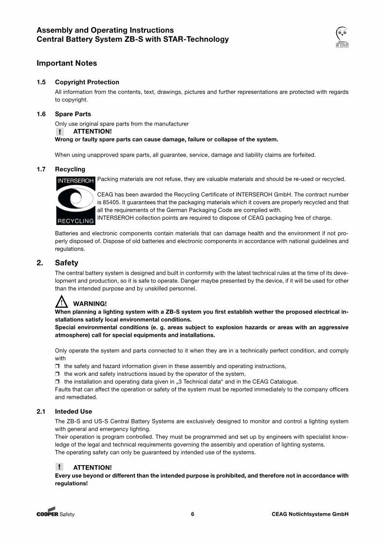
1.1 Description of SymbolsImportant safety notes are marked with symbols in these instructions. These stated notes have to be observed essentially.
WARNING! DANGER! RISK OF INJURY OR DEATH!Signifies notes which, when not observed, can cause impairment of health, (steady) injury or death.
ATTENTION! DAMAGE TO PROPERTY!Signifies notes which, when not observed, can cause damage to property and even the collapse of the system.
NOTE!Includes important hints and advice that is important for failure-free operation.
1.2 Information regarding these InstructionsThese operating instructions show the safe and proper handling with the system. The stated safety no-tes and instructions as well as the local accident prevention- and safety regulations have to be observed. Before working with the system, the instructions have to be read carefully, especially the chapter „Safety Instruc-tions“.The figures and circuit diagrams contained in these assembly and operating instructions are in part intended only to illustrate the products which are described. In all cases wherer dimensionally accurate work is required, orr accurate drawings or circuit diagrams that reflect the specifics of the site are required, the drawings and plans that have been created specially for the lighting system must be followed.
1.3 Further Applicable DocumentsIn the systems, components from other manufacturers are mounted. These purchasing-components are checked according to danger evaluation by the manufacturer. They declare the compliance of the construction with the European and national regulations.
1.4 Liability and GuaranteeAll information and notes in these instructions are compiled according to the valid regulations, the state of the art, our long-standing knowledge and experience.Keep the instructions near to the system, accessible for every person working with the system and at all times.Read the instructions carefully before working on and with the system!CEAG Notlichtsysteme GmbH can accept no liability and/or give no warranty in respect of any defects that may occur with the supply and intallation of CEAG emergency lighting systems and luminaires on the basis of other standards and regulations which are mandatory in complete installation packages in conjunction with CEAG pro-ducts. You must also comply with all statutes, standards and directives of the country in which the system is installed and operated.
CEAG will give no warranty or accept any liability for damage or consequential damage caused as a result ofr improper use,r failure to comply with regulations and codes of conduct for the safe operation of the system,r unauthorised or inexpert modifications to the connections and settings of the system, or to the programming of the system,r operating proscribed or unsuitable devices or groups of devices in the ZB-S system.
CEAG Notlichtsysteme GmbH6
Assembly and Operating Instructions Central Battery System ZB-S with STAR-Technology
1.5 Copyright ProtectionAll information from the contents, text, drawings, pictures and further representations are protected with regards to copyright.
1.6 Spare PartsOnly use original spare parts from the manufacturer
ATTENTION!Wrong or faulty spare parts can cause damage, failure or collapse of the system. When using unapproved spare parts, all guarantee, service, damage and liability claims are forfeited.
1.7 RecyclingPacking materials are not refuse, they are valuable materials and should be re-used or recycled.
CEAG has been awarded the Recycling Certificate of INTERSEROH GmbH. The contract number is 85405. It guarantees that the packaging materials which it covers are properly recycled and that all the requirements of the German Packaging Code are complied with.INTERSEROH collection points are required to dispose of CEAG packaging free of charge.
Batteries and electronic components contain materials that can damage health and the environment if not pro-perly disposed of. Dispose of old batteries and electronic components in accordance with national guidelines and regulations.
2. SafetyThe central battery system is designed and built in conformity with the latest technical rules at the time of its deve-lopment and production, so it is safe to operate. Danger maybe presented by the device, if it will be used for other than the intended purpose and by unskilled personnel.
WARNING!When planning a lighting system with a ZB-S system you first establish wether the proposed electrical in-stallations satisfy local environmental conditions.Special environmental conditions (e. g. areas subject to explosion hazards or areas with an aggressive atmosphere) call for special equipments and installations.
Only operate the system and parts connected to it when they are in a technically perfect condition, and comply withr the safety and hazard information given in these assembly and operating instructions,r the work and safety instructions issued by the operator of the system,r the installation and operating data given in „3 Technical data“ and in the CEAG Catalogue.Faults that can affect the operation or safety of the system must be reported immediately to the company officers and remediated.
2.1 Inteded UseThe ZB-S and US-S Central Battery Systems are exclusively designed to monitor and control a lighting system with general and emergency lighting.Their operation is program controlled. They must be programmed and set up by engineers with specialist know-ledge of the legal and technical requirements governing the assembly and operation of lighting systems.The operating safety can only be guaranteed by intended use of the systems.
ATTENTION!Every use beyond or different than the intended purpose is prohibited, and therefore not in accordance with regulations!
Important Notes
CEAG Notlichtsysteme GmbH7
Assembly and Operating Instructions Central Battery System ZB-S with STAR-Technology
2.2 Contents of Operating InstructionsEvery person, ordered to work with the system, has to read the instructions carefully to understand them before work begins. This takes also place when the person has already worked with a similar kind of battery or was in-structed by the manufacturer.
2.3 Changes and Modifications to the SystemTo avoid danger and to assure optimum performance, changes and modifications to the system are not allowed, except when the manufacturer has approved them.Any work involved in extensions, conversions or repairs and which is not described in this manual must be carried out by specially trained technical and service personnel (of the manufacturer CEAG or of CEAG-authorised distri-bution and service contractors)!
2.4 Responsibility of the OperatorKeep the instructions near to the system, accessible for every person working with the system and at all times. The System must be in a proper and safe condition when using it. System has to be checked for intactness before using it.Adhere to the information of the instructions completely!
2.5 Personnel RequirementsOnly authorised and skilled personnel are allowed to work on and with the system. The personnel must have re-ceived instructions regarding the existing danger.Skilled personnel refers to those with expert training, with knowledge and experience as well as knowledge of the relevant regulations. He should be able to evaluate his work and recognize the presence of danger.Personnel without the necessary knowledge must r have received qualified and proper training,r get their tasks and activities by full description for complete understandingr carry out the activities under the supervision and control of skilled and qualified personnel.
2.6 Operational SafetyObserving the stated safety instructions and regulations can avoid damage to property and people when working with the system.However the following organisational measurements must be specified in writing and be kept:r Duties of information and reporting (start, duration, end of the work)r Safety measures while the work is being carried out: e. g. standby lighting, power supply isolation and lock- out (e. g. removing the fuses, key-operated switch, safety signage) r Safety equipment for the personnel carrying out the work on the plant (s. chapter 2.7)r Safety equipment providing protection from hazards caused by adjacent plant (e. g. safety grilles, barriers, making safe of roads)Attend to the ESD-protection during working at the system!The applicable work and safety regulations are set out in these assembly and operating instructions, and inr the management´s internal organisational instructions (example see above)r and the general and specialist technical guidelines and accident prevention regulations.
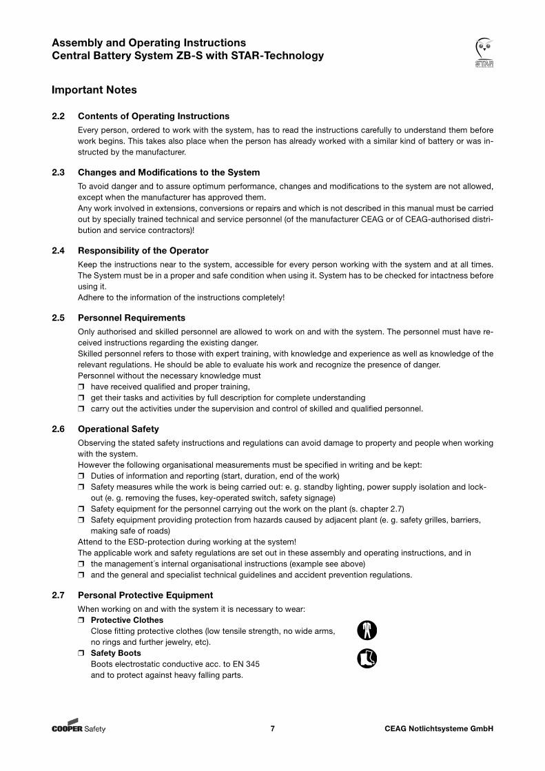
2.7 Personal Protective EquipmentWhen working on and with the system it is necessary to wear:r Protective Clothes Close fitting protective clothes (low tensile strength, no wide arms, no rings and further jewelry, etc).r Safety Boots Boots electrostatic conductive acc. to EN 345 and to protect against heavy falling parts.
Important Notes
CEAG Notlichtsysteme GmbH8
Assembly and Operating Instructions Central Battery System ZB-S with STAR-Technology
Technical Data
3. Technical Data
3.1 Data Sheet for ZB-S/26
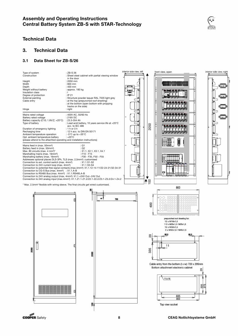
Type of system : ZB-S 26Construction : Sheet steel cabinet with partial viewing window in the doorHeight : 2050 mmWidth : 800 mmDepth : 400 mmWeight without battery : approx. 180 kgInsulation class : IDegree of protection : IP 21External painting : Structure powder laquer RAL 7035 light greyCable entry : at the top (prepunched roof sheeting) : at the bottom (open bottom with propping tracks on the side)Hinge : right
Mains rated voltage : 400V AC, 50/60 HzBattery rated voltage : 216V DCBattery capacity (C10; 1.8V/Z; +20°C) : 23.3-354 AhType of battery : Lead acid battery, 10 years service life at +20°C acc. to IEC 486Duration of emergency lighting : 1 h or 3 hRecharging time : 12 h acc. to DIN EN 50171Ambient temperature operation : -5°C up to +35°COpt. ambient temperature battery : +20°C(please attend to the attachted operating and installation instructions)
Mains feed in (max. 50mm²) : Q1Battery feed in (max. 50mm²) : Q2Max. 80 circuits (max. 4 mm²)* : X1.1, X2.1, X3.1, X4.1Marshalling mains (max. 16mm²) : F10 - F15Marshalling battery (max. 16mm²) : F30 - F35, F50 - F55Addresses optional places DLS-3Ph, TLS (max. 2,5mm²): customisedConnection to ext. control switch (max. 4mm²) : X1.1.S1-S2Connection to 24V current loop (max. 4mm²) : X1.1.S3-S4Connection to potential-free signal contacts (max.4mm²): X1.1.12-14-11/22-24-21/32-34-31Connection to CG-S Bus (max. 4mm²) : X1.1.A-BConnection to RS485 Bus (max. 4mm²) : X1.1.RS485.A-BConnection to 24V analog output (max. 4mm²): X1.1.+24V Out--24V OutConnection to 24V analog input (max.4mm²): X1.1.Z1.1-Z1.2/Z2.1-Z2.2/Z3.1-Z3.2/Z4.1-Z4.2
* Max. 2.5mm² flexible with wiring sleeve. The final circuits get wired customised.
CEAG Notlichtsysteme GmbH9
Assembly and Operating Instructions Central Battery System ZB-S with STAR-Technology
Technical Data
3.2 Data Sheet for ZB-S/18
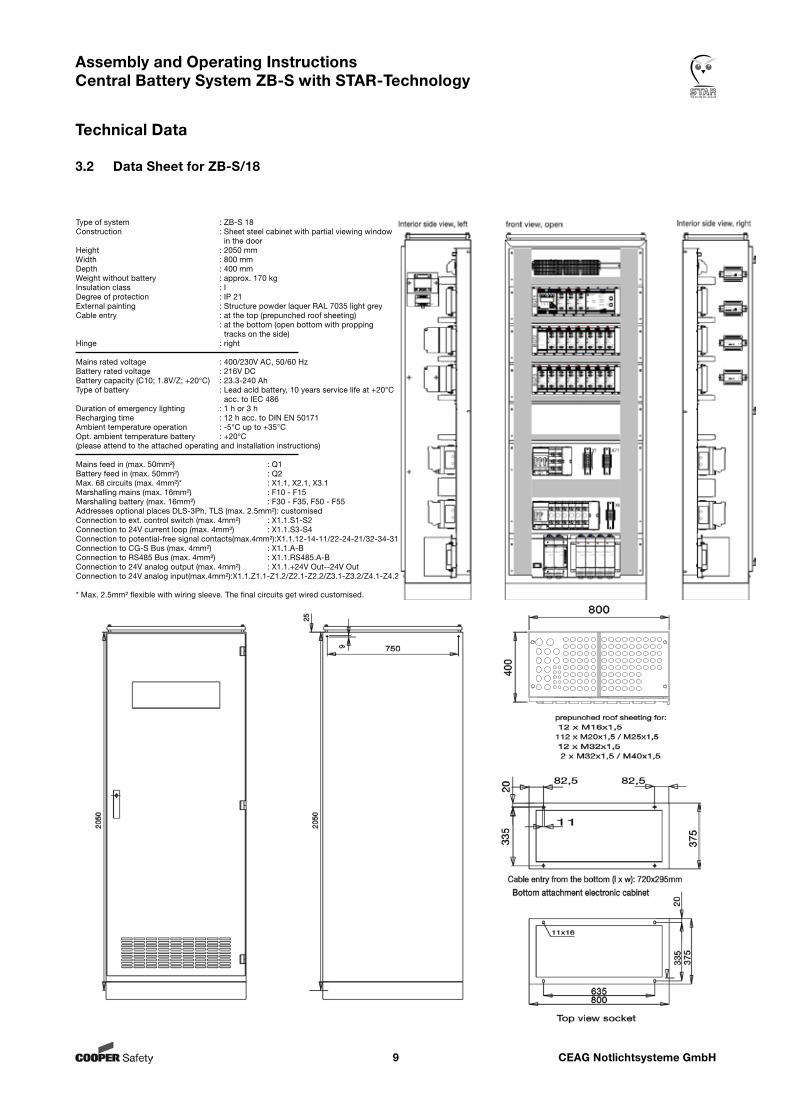
Type of system : ZB-S 18Construction : Sheet steel cabinet with partial viewing window in the doorHeight : 2050 mmWidth : 800 mmDepth : 400 mmWeight without battery : approx. 170 kgInsulation class : IDegree of protection : IP 21External painting : Structure powder laquer RAL 7035 light greyCable entry : at the top (prepunched roof sheeting) : at the bottom (open bottom with propping tracks on the side)Hinge : right
Mains rated voltage : 400/230V AC, 50/60 HzBattery rated voltage : 216V DCBattery capacity (C10; 1.8V/Z; +20°C) : 23.3-240 AhType of battery : Lead acid battery, 10 years service life at +20°C acc. to IEC 486Duration of emergency lighting : 1 h or 3 hRecharging time : 12 h acc. to DIN EN 50171Ambient temperature operation : -5°C up to +35°COpt. ambient temperature battery : +20°C(please attend to the attached operating and installation instructions)
Mains feed in (max. 50mm²) : Q1Battery feed in (max. 50mm²) : Q2Max. 68 circuits (max. 4mm²)* : X1.1, X2.1, X3.1Marshalling mains (max. 16mm²) : F10 - F15Marshalling battery (max. 16mm²) : F30 - F35, F50 - F55Addresses optional places DLS-3Ph, TLS (max. 2.5mm²): customisedConnection to ext. control switch (max. 4mm²) : X1.1.S1-S2Connection to 24V current loop (max. 4mm²) : X1.1.S3-S4Connection to potential-free signal contacts(max.4mm²):X1.1.12-14-11/22-24-21/32-34-31Connection to CG-S Bus (max. 4mm²) : X1.1.A-BConnection to RS485 Bus (max. 4mm²) : X1.1.RS485.A-BConnection to 24V analog output (max. 4mm²) : X1.1.+24V Out--24V OutConnection to 24V analog input(max.4mm²):X1.1.Z1.1-Z1.2/Z2.1-Z2.2/Z3.1-Z3.2/Z4.1-Z4.2
* Max. 2.5mm² flexible with wiring sleeve. The final circuits get wired customised.
CEAG Notlichtsysteme GmbH10
Assembly and Operating Instructions Central Battery System ZB-S with STAR-Technology
Technical Data
3.3 Data Sheet for ZB-S/LAD
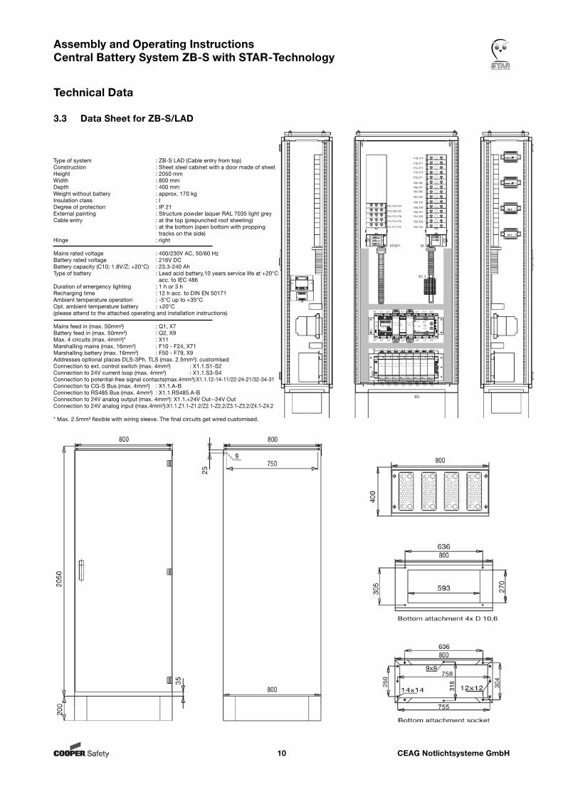
Type of system : ZB-S LAD (Cable entry from top)Construction : Sheet steel cabinet with a door made of sheetHeight : 2050 mmWidth : 800 mmDepth : 400 mmWeight without battery : approx. 170 kgInsulation class : IDegree of protection : IP 21External painting : Structure powder laquer RAL 7035 light greyCable entry : at the top (prepunched roof sheeting) : at the bottom (open bottom with propping tracks on the side)Hinge : right
Mains rated voltage : 400/230V AC, 50/60 HzBattery rated voltage : 216V DCBattery capacity (C10; 1.8V/Z; +20°C) : 23.3-240 AhType of battery : Lead acid battery,10 years service life at +20°C acc. to IEC 486Duration of emergency lighting : 1 h or 3 hRecharging time : 12 h acc. to DIN EN 50171Ambient temperature operation : -5°C up to +35°COpt. ambient temperature battery : +20°C(please attend to the attached operating and installation instructions)
Mains feed in (max. 50mm²) : Q1, X7Battery feed in (max. 50mm²) : Q2, X9Max. 4 circuits (max. 4mm²)* : X11Marshalling mains (max. 16mm²) : F10 - F24, X71Marshalling battery (max. 16mm²) : F50 - F79, X9Addresses optional places DLS-3Ph, TLS (max. 2.5mm²): customisedConnection to ext. control switch (max. 4mm²) : X1.1.S1-S2Connection to 24V current loop (max. 4mm²) : X1.1.S3-S4Connection to potential-free signal contacts(max.4mm²):X1.1.12-14-11/22-24-21/32-34-31Connection to CG-S Bus (max. 4mm²) : X1.1.A-BConnection to RS485 Bus (max. 4mm²) : X1.1.RS485.A-BConnection to 24V analog output (max. 4mm²): X1.1.+24V Out--24V OutConnection to 24V analog input (max.4mm²):X1.1.Z1.1-Z1.2/Z2.1-Z2.2/Z3.1-Z3.2/Z4.1-Z4.2
* Max. 2.5mm² flexible with wiring sleeve. The final circuits get wired customised.
CEAG Notlichtsysteme GmbH11
Assembly and Operating Instructions Central Battery System ZB-S with STAR-Technology
Technical Data
3.4 Data Sheet for ZB-S/10C
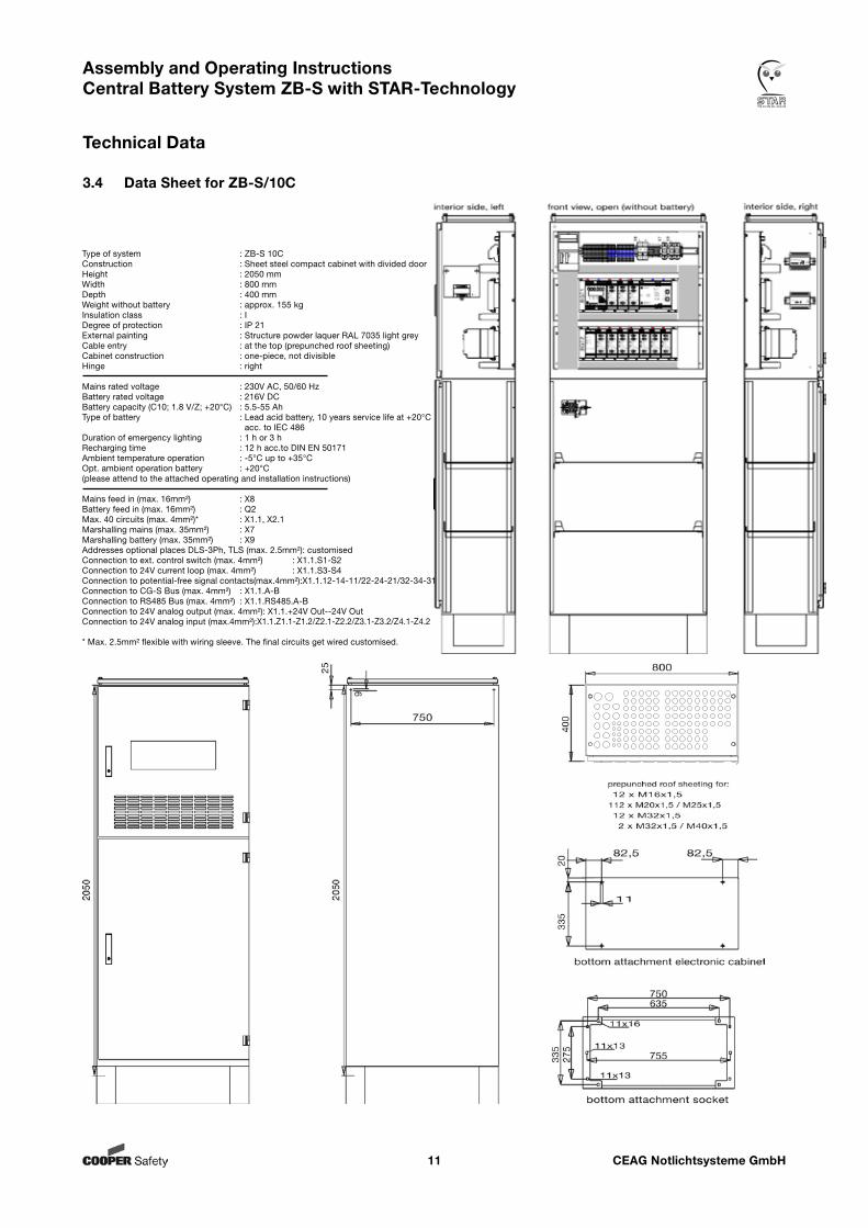
Type of system : ZB-S 10CConstruction : Sheet steel compact cabinet with divided doorHeight : 2050 mmWidth : 800 mmDepth : 400 mmWeight without battery : approx. 155 kgInsulation class : IDegree of protection : IP 21External painting : Structure powder laquer RAL 7035 light greyCable entry : at the top (prepunched roof sheeting)Cabinet construction : one-piece, not divisibleHinge : right
Mains rated voltage : 230V AC, 50/60 HzBattery rated voltage : 216V DCBattery capacity (C10; 1.8 V/Z; +20°C) : 5.5-55 AhType of battery : Lead acid battery, 10 years service life at +20°C acc. to IEC 486Duration of emergency lighting : 1 h or 3 hRecharging time : 12 h acc.to DIN EN 50171Ambient temperature operation : -5°C up to +35°COpt. ambient operation battery : +20°C(please attend to the attached operating and installation instructions)
Mains feed in (max. 16mm²) : X8Battery feed in (max. 16mm²) : Q2Max. 40 circuits (max. 4mm²)* : X1.1, X2.1Marshalling mains (max. 35mm²) : X7Marshalling battery (max. 35mm²) : X9 Addresses optional places DLS-3Ph, TLS (max. 2.5mm²): customisedConnection to ext. control switch (max. 4mm²) : X1.1.S1-S2Connection to 24V current loop (max. 4mm²) : X1.1.S3-S4Connection to potential-free signal contacts(max.4mm²):X1.1.12-14-11/22-24-21/32-34-31Connection to CG-S Bus (max. 4mm²) : X1.1.A-BConnection to RS485 Bus (max. 4mm²) : X1.1.RS485.A-BConnection to 24V analog output (max. 4mm²): X1.1.+24V Out--24V OutConnection to 24V analog input (max.4mm²):X1.1.Z1.1-Z1.2/Z2.1-Z2.2/Z3.1-Z3.2/Z4.1-Z4.2
* Max. 2.5mm² flexible with wiring sleeve. The final circuits get wired customised.
CEAG Notlichtsysteme GmbH12
Assembly and Operating Instructions Central Battery System ZB-S with STAR-Technology
Technical Data
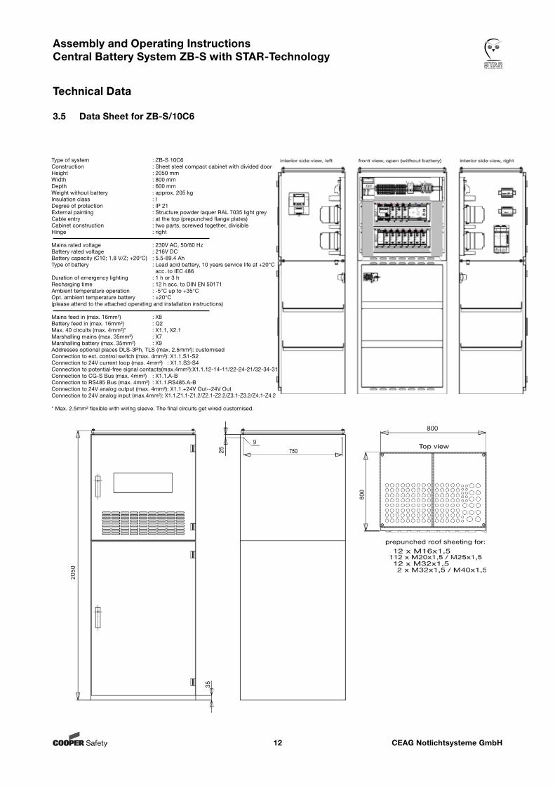
3.5 Data Sheet for ZB-S/10C6
Type of system : ZB-S 10C6Construction : Sheet steel compact cabinet with divided doorHeight : 2050 mmWidth : 800 mmDepth : 600 mmWeight without battery : approx. 205 kgInsulation class : IDegree of protection : IP 21External painting : Structure powder laquer RAL 7035 light greyCable entry : at the top (prepunched flange plates)Cabinet construction : two parts, screwed together, divisibleHinge : right
Mains rated voltage : 230V AC, 50/60 HzBattery rated voltage : 216V DCBattery capacity (C10; 1.8 V/Z; +20°C) : 5.5-89.4 AhType of battery : Lead acid battery, 10 years service life at +20°C acc. to IEC 486Duration of emergency lighting : 1 h or 3 hRecharging time : 12 h acc. to DIN EN 50171Ambient temperature operation : -5°C up to +35°COpt. ambient temperature battery : +20°C(please attend to the attached operating and installation instructions)
Mains feed in (max. 16mm²) : X8Battery feed in (max. 16mm²) : Q2Max. 40 circuits (max. 4mm²)* : X1.1, X2.1Marshalling mains (max. 35mm²) : X7Marshalling battery (max. 35mm²) : X9 Addresses optional places DLS-3Ph, TLS (max. 2.5mm²): customisedConnection to ext. control switch (max. 4mm²): X1.1.S1-S2Connection to 24V current loop (max. 4mm²) : X1.1.S3-S4Connection to potential-free signal contacts(max.4mm²):X1.1.12-14-11/22-24-21/32-34-31Connection to CG-S Bus (max. 4mm²) : X1.1.A-BConnection to RS485 Bus (max. 4mm²) : X1.1.RS485.A-BConnection to 24V analog output (max. 4mm²): X1.1.+24V Out--24V OutConnection to 24V analog input (max.4mm²): X1.1.Z1.1-Z1.2/Z2.1-Z2.2/Z3.1-Z3.2/Z4.1-Z4.2
* Max. 2.5mm² flexible with wiring sleeve. The final circuits get wired customised.
CEAG Notlichtsysteme GmbH13
Assembly and Operating Instructions Central Battery System ZB-S with STAR-Technology
Technical Data
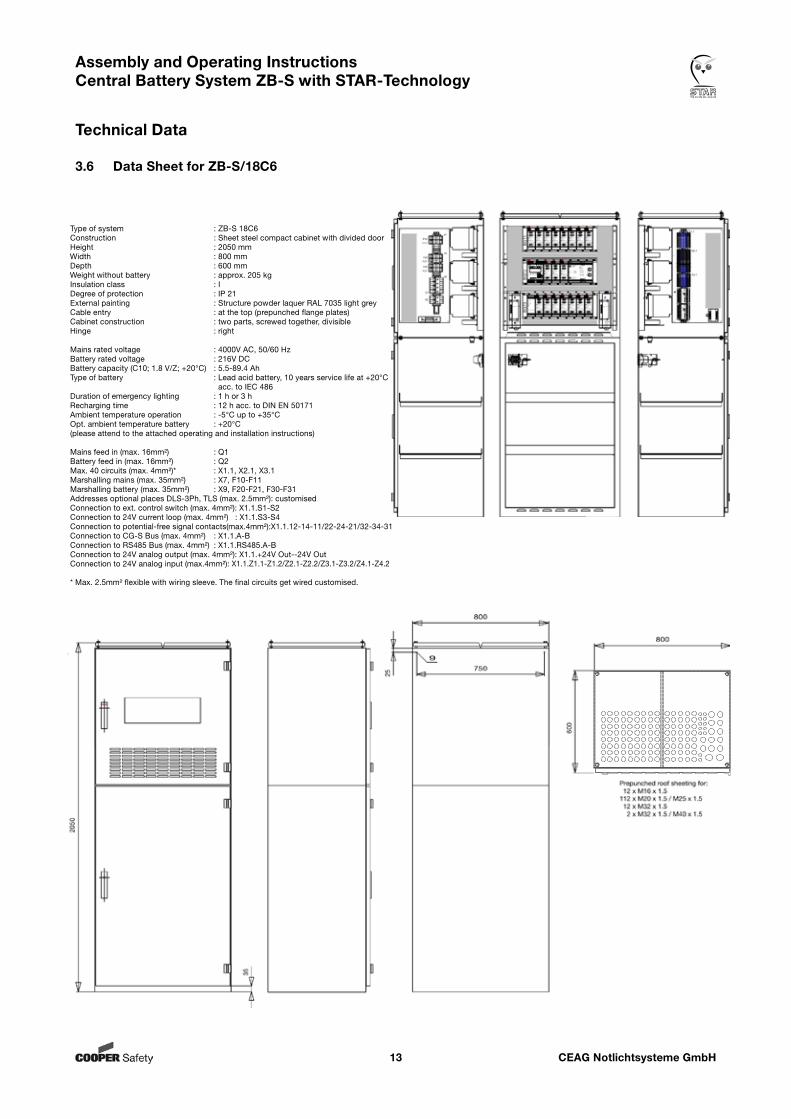
3.6 Data Sheet for ZB-S/18C6
Type of system : ZB-S 18C6Construction : Sheet steel compact cabinet with divided doorHeight : 2050 mmWidth : 800 mmDepth : 600 mmWeight without battery : approx. 205 kgInsulation class : IDegree of protection : IP 21External painting : Structure powder laquer RAL 7035 light greyCable entry : at the top (prepunched flange plates)Cabinet construction : two parts, screwed together, divisibleHinge : right
Mains rated voltage : 4000V AC, 50/60 HzBattery rated voltage : 216V DCBattery capacity (C10; 1.8 V/Z; +20°C) : 5.5-89.4 AhType of battery : Lead acid battery, 10 years service life at +20°C acc. to IEC 486Duration of emergency lighting : 1 h or 3 hRecharging time : 12 h acc. to DIN EN 50171Ambient temperature operation : -5°C up to +35°COpt. ambient temperature battery : +20°C(please attend to the attached operating and installation instructions)
Mains feed in (max. 16mm²) : Q1Battery feed in (max. 16mm²) : Q2Max. 40 circuits (max. 4mm²)* : X1.1, X2.1, X3.1Marshalling mains (max. 35mm²) : X7, F10-F11Marshalling battery (max. 35mm²) : X9, F20-F21, F30-F31 Addresses optional places DLS-3Ph, TLS (max. 2.5mm²): customisedConnection to ext. control switch (max. 4mm²): X1.1.S1-S2Connection to 24V current loop (max. 4mm²) : X1.1.S3-S4Connection to potential-free signal contacts(max.4mm²):X1.1.12-14-11/22-24-21/32-34-31Connection to CG-S Bus (max. 4mm²) : X1.1.A-BConnection to RS485 Bus (max. 4mm²) : X1.1.RS485.A-BConnection to 24V analog output (max. 4mm²): X1.1.+24V Out--24V OutConnection to 24V analog input (max.4mm²): X1.1.Z1.1-Z1.2/Z2.1-Z2.2/Z3.1-Z3.2/Z4.1-Z4.2
* Max. 2.5mm² flexible with wiring sleeve. The final circuits get wired customised.
CEAG Notlichtsysteme GmbH14
Assembly and Operating Instructions Central Battery System ZB-S with STAR-Technology
Technical Data
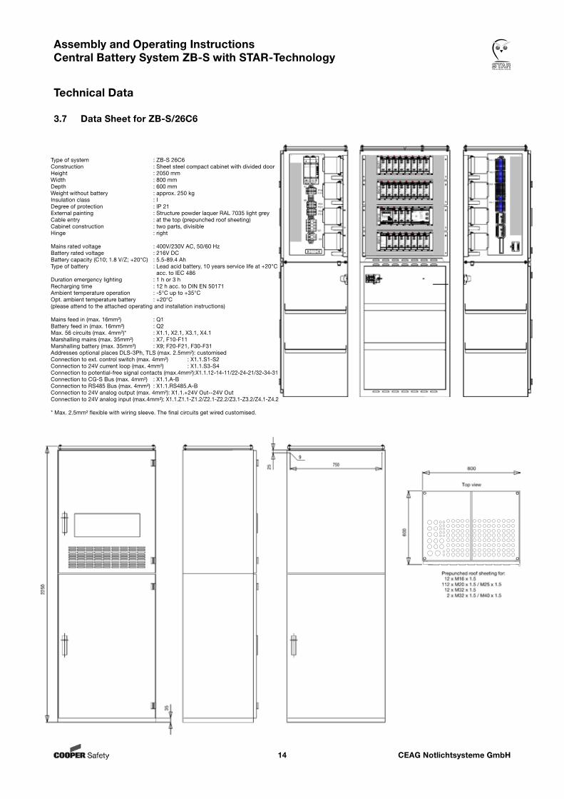
3.7 Data Sheet for ZB-S/26C6
Type of system : ZB-S 26C6Construction : Sheet steel compact cabinet with divided doorHeight : 2050 mmWidth : 800 mmDepth : 600 mmWeight without battery : approx. 250 kgInsulation class : IDegree of protection : IP 21External painting : Structure powder laquer RAL 7035 light greyCable entry : at the top (prepunched roof sheeting)Cabinet construction : two parts, divisibleHinge : right
Mains rated voltage : 400V/230V AC, 50/60 HzBattery rated voltage : 216V DCBattery capacity (C10; 1.8 V/Z; +20°C) : 5.5-89.4 AhType of battery : Lead acid battery, 10 years service life at +20°C acc. to IEC 486Duration emergency lighting : 1 h or 3 hRecharging time : 12 h acc. to DIN EN 50171Ambient temperature operation : -5°C up to +35°COpt. ambient temperature battery : +20°C(please attend to the attached operating and installation instructions)
Mains feed in (max. 16mm²) : Q1Battery feed in (max. 16mm²) : Q2Max. 56 circuits (max. 4mm²)* : X1.1, X2.1, X3.1, X4.1Marshalling mains (max. 35mm²) : X7, F10-F11Marshalling battery (max. 35mm²) : X9; F20-F21, F30-F31 Addresses optional places DLS-3Ph, TLS (max. 2.5mm²): customisedConnection to ext. control switch (max. 4mm²) : X1.1.S1-S2Connection to 24V current loop (max. 4mm²) : X1.1.S3-S4Connection to potential-free signal contacts (max.4mm²):X1.1.12-14-11/22-24-21/32-34-31Connection to CG-S Bus (max. 4mm²) : X1.1.A-BConnection to RS485 Bus (max. 4mm²) : X1.1.RS485.A-BConnection to 24V analog output (max. 4mm²): X1.1.+24V Out--24V OutConnection to 24V analog input (max.4mm²): X1.1.Z1.1-Z1.2/Z2.1-Z2.2/Z3.1-Z3.2/Z4.1-Z4.2
* Max. 2.5mm² flexible with wiring sleeve. The final circuits get wired customised.
CEAG Notlichtsysteme GmbH15
Assembly and Operating Instructions Central Battery System ZB-S with STAR-Technology
Technical Data
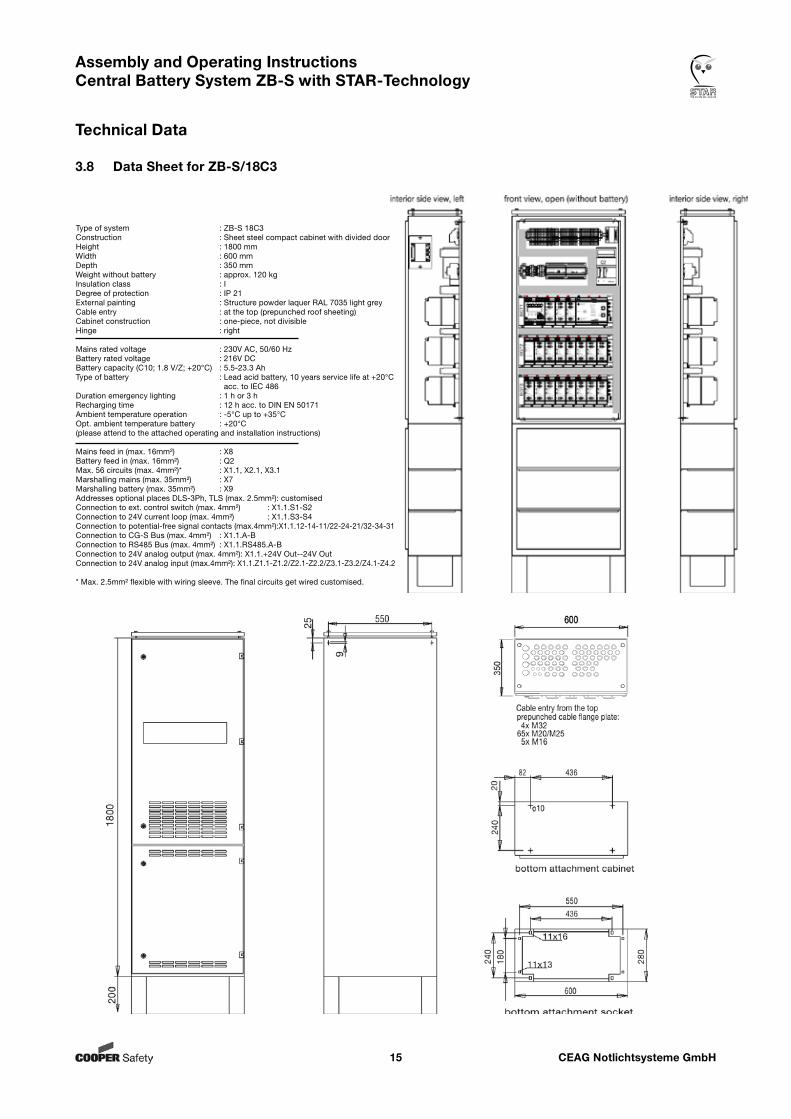
3.8 Data Sheet for ZB-S/18C3
Type of system : ZB-S 18C3Construction : Sheet steel compact cabinet with divided doorHeight : 1800 mmWidth : 600 mmDepth : 350 mmWeight without battery : approx. 120 kgInsulation class : IDegree of protection : IP 21External painting : Structure powder laquer RAL 7035 light greyCable entry : at the top (prepunched roof sheeting)Cabinet construction : one-piece, not divisibleHinge : right
Mains rated voltage : 230V AC, 50/60 HzBattery rated voltage : 216V DCBattery capacity (C10; 1.8 V/Z; +20°C) : 5.5-23.3 AhType of battery : Lead acid battery, 10 years service life at +20°C acc. to IEC 486Duration emergency lighting : 1 h or 3 hRecharging time : 12 h acc. to DIN EN 50171Ambient temperature operation : -5°C up to +35°COpt. ambient temperature battery : +20°C(please attend to the attached operating and installation instructions)
Mains feed in (max. 16mm²) : X8Battery feed in (max. 16mm²) : Q2Max. 56 circuits (max. 4mm²)* : X1.1, X2.1, X3.1Marshalling mains (max. 35mm²) : X7Marshalling battery (max. 35mm²) : X9 Addresses optional places DLS-3Ph, TLS (max. 2.5mm²): customisedConnection to ext. control switch (max. 4mm²) : X1.1.S1-S2Connection to 24V current loop (max. 4mm²) : X1.1.S3-S4Connection to potential-free signal contacts (max.4mm²):X1.1.12-14-11/22-24-21/32-34-31Connection to CG-S Bus (max. 4mm²) : X1.1.A-BConnection to RS485 Bus (max. 4mm²) : X1.1.RS485.A-BConnection to 24V analog output (max. 4mm²): X1.1.+24V Out--24V OutConnection to 24V analog input (max.4mm²): X1.1.Z1.1-Z1.2/Z2.1-Z2.2/Z3.1-Z3.2/Z4.1-Z4.2
* Max. 2.5mm² flexible with wiring sleeve. The final circuits get wired customised.
CEAG Notlichtsysteme GmbH16
Assembly and Operating Instructions Central Battery System ZB-S with STAR-Technology
Technical Data
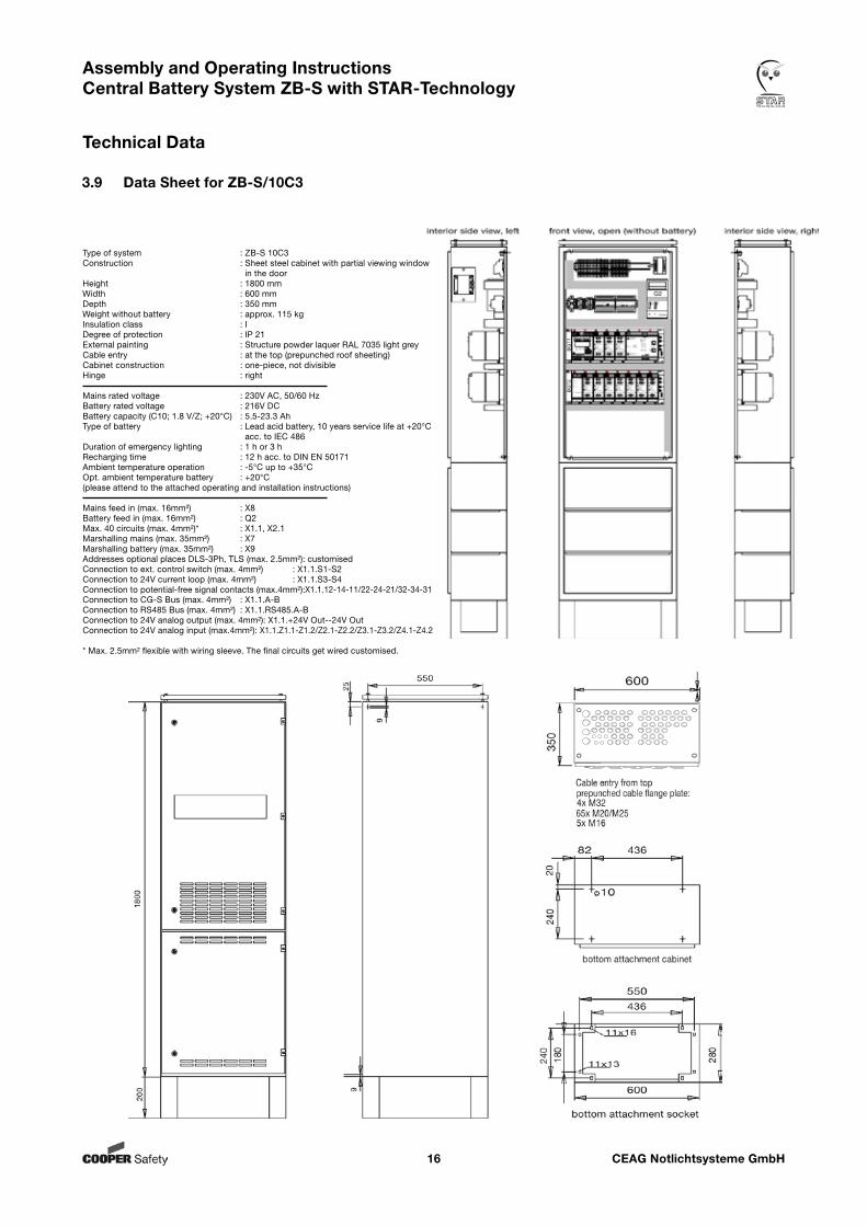
3.9 Data Sheet for ZB-S/10C3
Type of system : ZB-S 10C3Construction : Sheet steel cabinet with partial viewing window in the doorHeight : 1800 mmWidth : 600 mmDepth : 350 mmWeight without battery : approx. 115 kgInsulation class : IDegree of protection : IP 21External painting : Structure powder laquer RAL 7035 light greyCable entry : at the top (prepunched roof sheeting)Cabinet construction : one-piece, not divisibleHinge : right
Mains rated voltage : 230V AC, 50/60 HzBattery rated voltage : 216V DCBattery capacity (C10; 1.8 V/Z; +20°C) : 5.5-23.3 AhType of battery : Lead acid battery, 10 years service life at +20°C acc. to IEC 486Duration of emergency lighting : 1 h or 3 hRecharging time : 12 h acc. to DIN EN 50171Ambient temperature operation : -5°C up to +35°COpt. ambient temperature battery : +20°C(please attend to the attached operating and installation instructions)
Mains feed in (max. 16mm²) : X8Battery feed in (max. 16mm²) : Q2Max. 40 circuits (max. 4mm²)* : X1.1, X2.1Marshalling mains (max. 35mm²) : X7Marshalling battery (max. 35mm²) : X9 Addresses optional places DLS-3Ph, TLS (max. 2.5mm²): customisedConnection to ext. control switch (max. 4mm²) : X1.1.S1-S2Connection to 24V current loop (max. 4mm²) : X1.1.S3-S4Connection to potential-free signal contacts (max.4mm²):X1.1.12-14-11/22-24-21/32-34-31Connection to CG-S Bus (max. 4mm²) : X1.1.A-BConnection to RS485 Bus (max. 4mm²) : X1.1.RS485.A-BConnection to 24V analog output (max. 4mm²): X1.1.+24V Out--24V OutConnection to 24V analog input (max.4mm²): X1.1.Z1.1-Z1.2/Z2.1-Z2.2/Z3.1-Z3.2/Z4.1-Z4.2
* Max. 2.5mm² flexible with wiring sleeve. The final circuits get wired customised.
CEAG Notlichtsysteme GmbH17
Assembly and Operating Instructions Central Battery System ZB-S with STAR-Technology
Technical Data
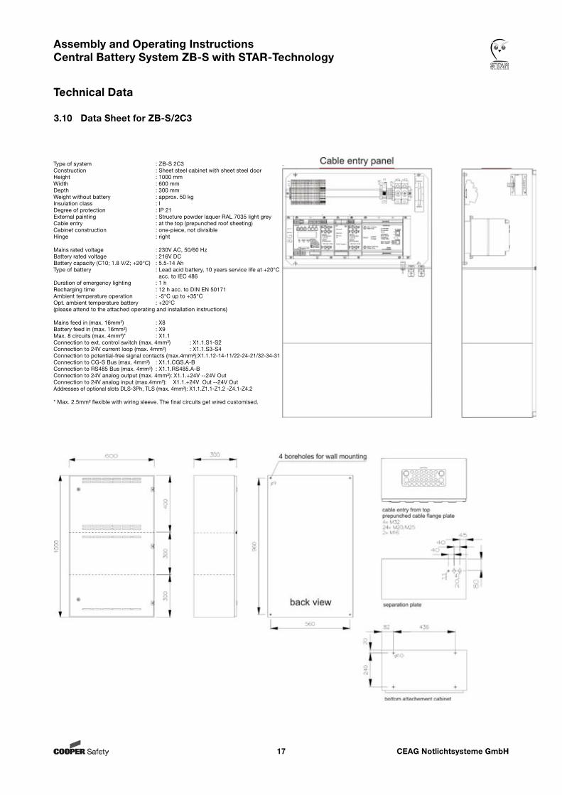
3.10 Data Sheet for ZB-S/2C3
Type of system : ZB-S 2C3Construction : Sheet steel cabinet with sheet steel doorHeight : 1000 mmWidth : 600 mmDepth : 300 mmWeight without battery : approx. 50 kgInsulation class : IDegree of protection : IP 21External painting : Structure powder laquer RAL 7035 light greyCable entry : at the top (prepunched roof sheeting)Cabinet construction : one-piece, not divisibleHinge : right
Mains rated voltage : 230V AC, 50/60 HzBattery rated voltage : 216V DCBattery capacity (C10; 1.8 V/Z; +20°C) : 5.5-14 AhType of battery : Lead acid battery, 10 years service life at +20°C acc. to IEC 486Duration of emergency lighting : 1 hRecharging time : 12 h acc. to DIN EN 50171Ambient temperature operation : -5°C up to +35°COpt. ambient temperature battery : +20°C(please attend to the attached operating and installation instructions)
Mains feed in (max. 16mm²) : X8Battery feed in (max. 16mm²) : X9Max. 8 circuits (max. 4mm²)* : X1.1Connection to ext. control switch (max. 4mm²) : X1.1.S1-S2Connection to 24V current loop (max. 4mm²) : X1.1.S3-S4Connection to potential-free signal contacts (max.4mm²):X1.1.12-14-11/22-24-21/32-34-31Connection to CG-S Bus (max. 4mm²) : X1.1.CGS.A-BConnection to RS485 Bus (max. 4mm²) : X1.1.RS485.A-BConnection to 24V analog output (max. 4mm²): X1.1.+24V --24V OutConnection to 24V analog input (max.4mm²): X1.1.+24V Out --24V Out Addresses of optional slots DLS-3Ph, TLS (max. 4mm²): X1.1.Z1.1-Z1.2 -Z4.1-Z4.2
* Max. 2.5mm² flexible with wiring sleeve. The final circuits get wired customised.
CEAG Notlichtsysteme GmbH18
Assembly and Operating Instructions Central Battery System ZB-S with STAR-Technology
Technical Data
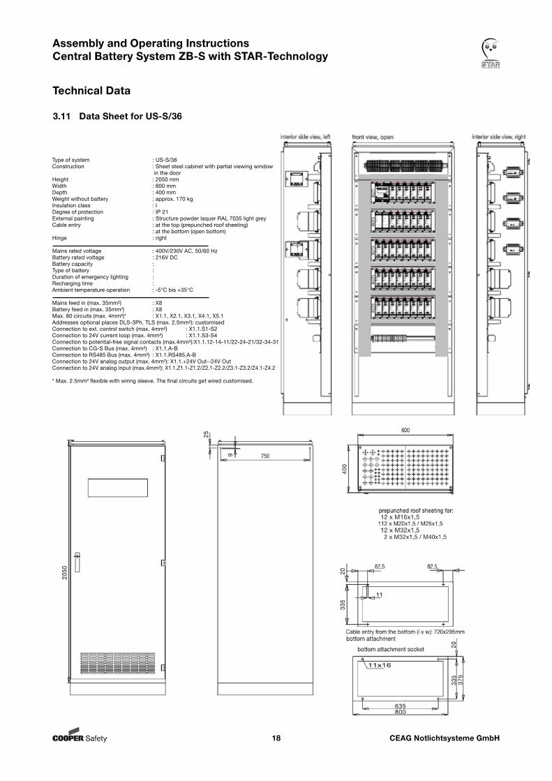
3.11 Data Sheet for US-S/36
Type of system : US-S/36Construction : Sheet steel cabinet with partial viewing window in the doorHeight : 2050 mmWidth : 800 mmDepth : 400 mmWeight without battery : approx. 170 kgInsulation class : IDegree of protection : IP 21External painting : Structure powder laquer RAL 7035 light greyCable entry : at the top (prepunched roof sheeting) : at the bottom (open bottom)Hinge : right
Mains rated voltage : 400V/230V AC, 50/60 HzBattery rated voltage : 216V DCBattery capacity : Type of battery : Duration of emergency lighting : Recharging time : Ambient temperature operation : -5°C bis +35°C
Mains feed in (max. 35mm²) : X8Battery feed in (max. 35mm²) : X8Max. 80 circuits (max. 4mm²)* : X1.1, X2.1, X3.1, X4.1, X5.1Addresses optional places DLS-3Ph, TLS (max. 2,5mm²): customisedConnection to ext. control switch (max. 4mm²) : X1.1.S1-S2Connection to 24V current loop (max. 4mm²) : X1.1.S3-S4Connection to potential-free signal contacts (max.4mm²):X1.1.12-14-11/22-24-21/32-34-31Connection to CG-S Bus (max. 4mm²) : X1.1.A-BConnection to RS485 Bus (max. 4mm²) : X1.1.RS485.A-BConnection to 24V analog output (max. 4mm²): X1.1.+24V Out--24V OutConnection to 24V analog input (max.4mm²): X1.1.Z1.1-Z1.2/Z2.1-Z2.2/Z3.1-Z3.2/Z4.1-Z4.2
* Max. 2.5mm² flexible with wiring sleeve. The final circuits get wired customised.
CEAG Notlichtsysteme GmbH19
Assembly and Operating Instructions Central Battery System ZB-S with STAR-Technology
Technical Data
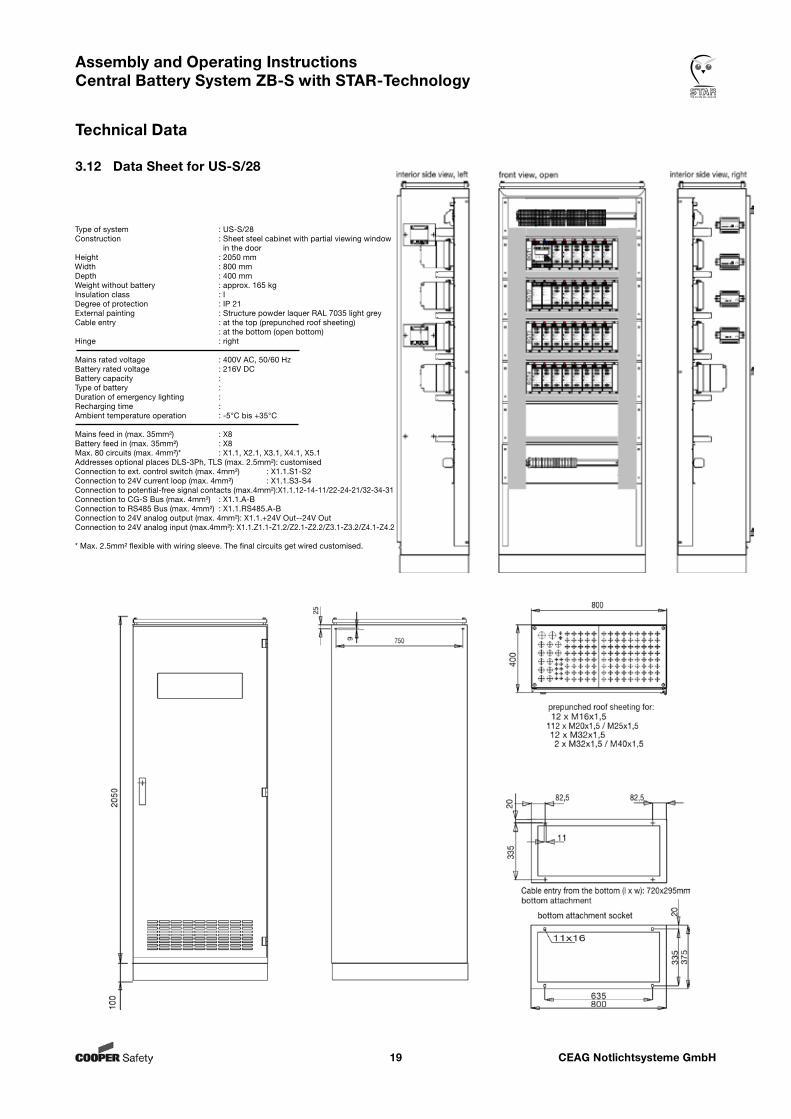
3.12 Data Sheet for US-S/28
Type of system : US-S/28Construction : Sheet steel cabinet with partial viewing window in the doorHeight : 2050 mmWidth : 800 mmDepth : 400 mmWeight without battery : approx. 165 kgInsulation class : IDegree of protection : IP 21External painting : Structure powder laquer RAL 7035 light greyCable entry : at the top (prepunched roof sheeting) : at the bottom (open bottom)Hinge : right
Mains rated voltage : 400V AC, 50/60 HzBattery rated voltage : 216V DCBattery capacity : Type of battery : Duration of emergency lighting : Recharging time : Ambient temperature operation : -5°C bis +35°C
Mains feed in (max. 35mm²) : X8Battery feed in (max. 35mm²) : X8Max. 80 circuits (max. 4mm²)* : X1.1, X2.1, X3.1, X4.1, X5.1Addresses optional places DLS-3Ph, TLS (max. 2.5mm²): customisedConnection to ext. control switch (max. 4mm²) : X1.1.S1-S2Connection to 24V current loop (max. 4mm²) : X1.1.S3-S4Connection to potential-free signal contacts (max.4mm²):X1.1.12-14-11/22-24-21/32-34-31Connection to CG-S Bus (max. 4mm²) : X1.1.A-BConnection to RS485 Bus (max. 4mm²) : X1.1.RS485.A-BConnection to 24V analog output (max. 4mm²): X1.1.+24V Out--24V OutConnection to 24V analog input (max.4mm²): X1.1.Z1.1-Z1.2/Z2.1-Z2.2/Z3.1-Z3.2/Z4.1-Z4.2
* Max. 2.5mm² flexible with wiring sleeve. The final circuits get wired customised.
CEAG Notlichtsysteme GmbH20
Assembly and Operating Instructions Central Battery System ZB-S with STAR-Technology
Technical Data
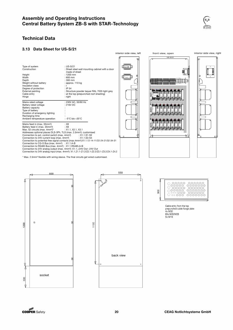
3.13 Data Sheet for US-S/21
Type of system : US-S/21Construction : Sheet steel wall mounting cabinet with a door made of sheetHeight : 1200 mmWidth : 600 mmDepth : 300 mmWeight without battery : approx. 110 kgInsulation class : IDegree of protection : IP 54External painting : Structure powder laquer RAL 7035 light greyCable entry : at the top (prepunched roof sheeting)Hinge : right
Mains rated voltage : 230V AC, 50/60 HzBattery rated voltage : 216V DCBattery capacity : Type of battery : Duration of emergency lighting : Recharging time : Ambient temperature operation : -5°C bis +35°C
Mains feed in (max. 35mm²) : X8Battery feed in (max. 35mm²) : X8Max. 52 circuits (max. 4mm²)* : X1.1, X2.1, X3.1Addresses optional places DLS-3Ph, TLS (max. 2.5mm²): customisedConnection to ext. control switch (max. 4mm²) : X1.1.S1-S2Connection to 24V current loop (max. 4mm²) : X1.1.S3-S4Connection to potential-free signal contacts (max.4mm²):X1.1.12-14-11/22-24-21/32-34-31Connection to CG-S Bus (max. 4mm²) : X1.1.A-BConnection to RS485 Bus (max. 4mm²) : X1.1.RS485.A-BConnection to 24V analog output (max. 4mm²): X1.1.+24V Out--24V OutConnection to 24V analog input (max. 4mm²): X1.1.Z1.1-Z1.2/Z2.1-Z2.2/Z3.1-Z3.2/Z4.1-Z4.2
* Max. 2.5mm² flexible with wiring sleeve. The final circuits get wired customised.
socket
back view
CEAG Notlichtsysteme GmbH21
Assembly and Operating Instructions Central Battery System ZB-S with STAR-Technology
Technical Data
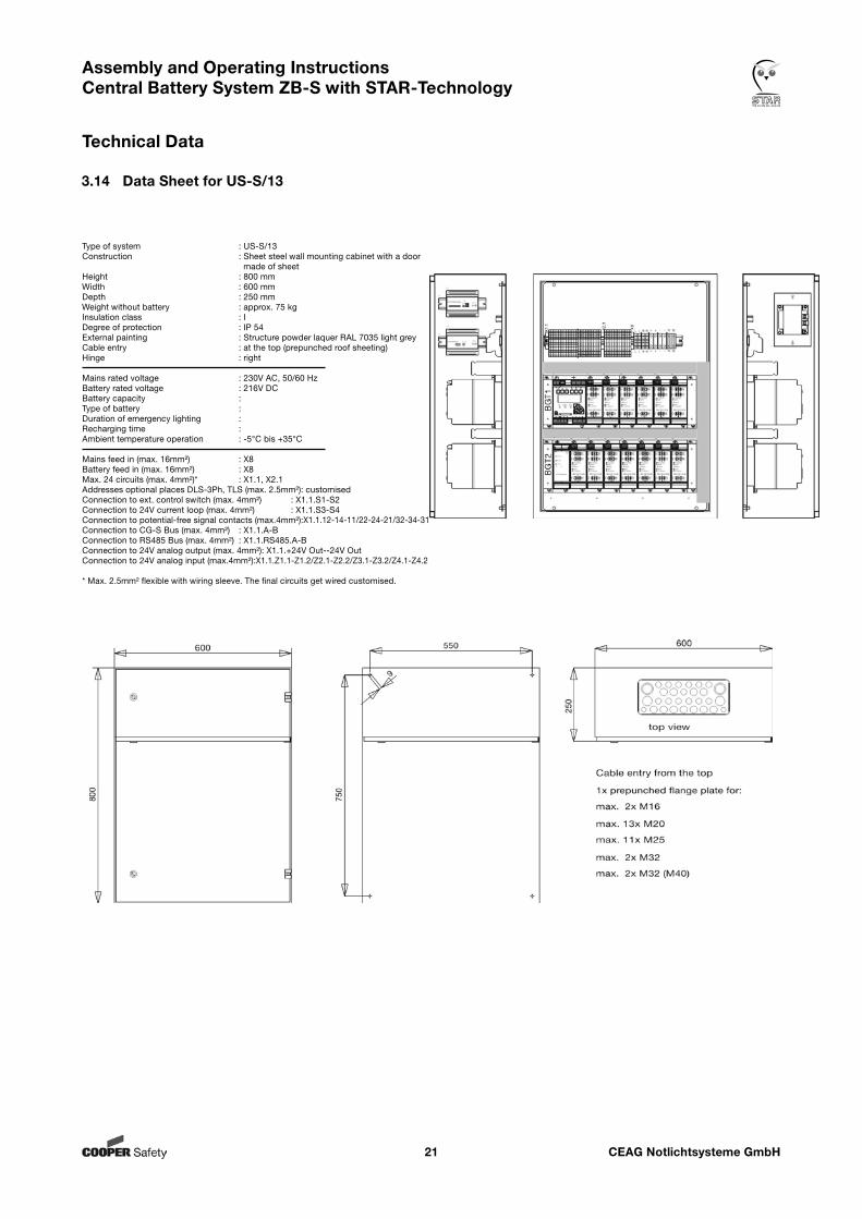
3.14 Data Sheet for US-S/13
Type of system : US-S/13Construction : Sheet steel wall mounting cabinet with a door made of sheetHeight : 800 mmWidth : 600 mmDepth : 250 mmWeight without battery : approx. 75 kgInsulation class : IDegree of protection : IP 54External painting : Structure powder laquer RAL 7035 light greyCable entry : at the top (prepunched roof sheeting)Hinge : right
Mains rated voltage : 230V AC, 50/60 HzBattery rated voltage : 216V DCBattery capacity : Type of battery : Duration of emergency lighting : Recharging time : Ambient temperature operation : -5°C bis +35°C
Mains feed in (max. 16mm²) : X8Battery feed in (max. 16mm²) : X8Max. 24 circuits (max. 4mm²)* : X1.1, X2.1Addresses optional places DLS-3Ph, TLS (max. 2.5mm²): customisedConnection to ext. control switch (max. 4mm²) : X1.1.S1-S2Connection to 24V current loop (max. 4mm²) : X1.1.S3-S4Connection to potential-free signal contacts (max.4mm²):X1.1.12-14-11/22-24-21/32-34-31Connection to CG-S Bus (max. 4mm²) : X1.1.A-BConnection to RS485 Bus (max. 4mm²) : X1.1.RS485.A-BConnection to 24V analog output (max. 4mm²): X1.1.+24V Out--24V OutConnection to 24V analog input (max.4mm²):X1.1.Z1.1-Z1.2/Z2.1-Z2.2/Z3.1-Z3.2/Z4.1-Z4.2
* Max. 2.5mm² flexible with wiring sleeve. The final circuits get wired customised.
CEAG Notlichtsysteme GmbH22
Assembly and Operating Instructions Central Battery System ZB-S with STAR-Technology
Technical Data
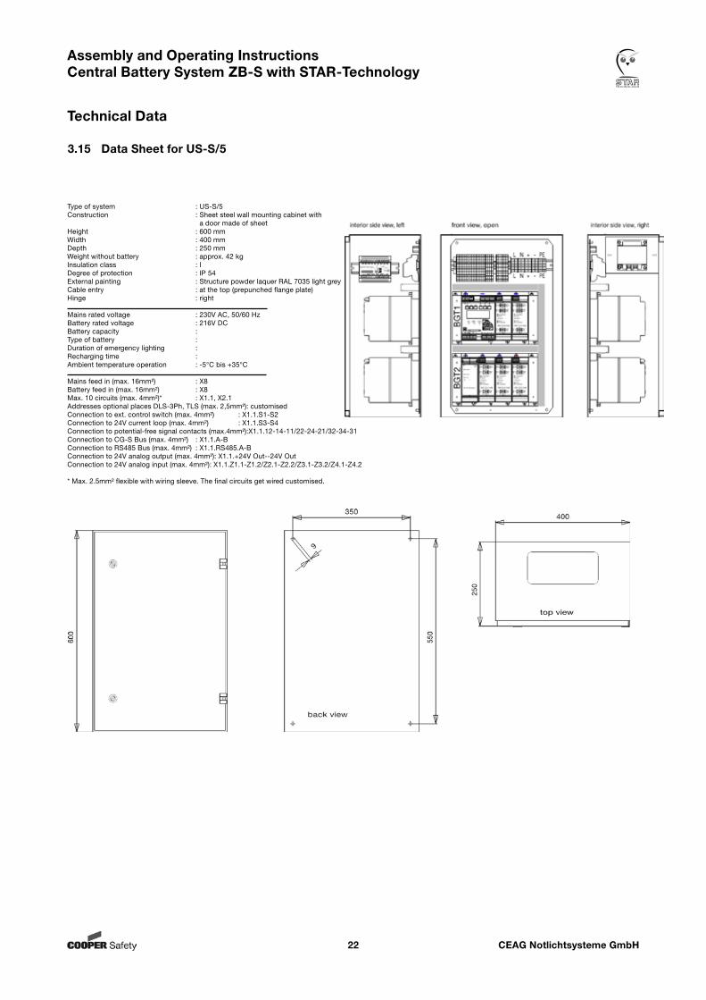
3.15 Data Sheet for US-S/5
Type of system : US-S/5Construction : Sheet steel wall mounting cabinet with a door made of sheetHeight : 600 mmWidth : 400 mmDepth : 250 mmWeight without battery : approx. 42 kgInsulation class : IDegree of protection : IP 54External painting : Structure powder laquer RAL 7035 light greyCable entry : at the top (prepunched flange plate)Hinge : right
Mains rated voltage : 230V AC, 50/60 HzBattery rated voltage : 216V DCBattery capacity : Type of battery : Duration of emergency lighting : Recharging time : Ambient temperature operation : -5°C bis +35°C
Mains feed in (max. 16mm²) : X8Battery feed in (max. 16mm²) : X8Max. 10 circuits (max. 4mm²)* : X1.1, X2.1Addresses optional places DLS-3Ph, TLS (max. 2,5mm²): customisedConnection to ext. control switch (max. 4mm²) : X1.1.S1-S2Connection to 24V current loop (max. 4mm²) : X1.1.S3-S4Connection to potential-free signal contacts (max.4mm²):X1.1.12-14-11/22-24-21/32-34-31Connection to CG-S Bus (max. 4mm²) : X1.1.A-BConnection to RS485 Bus (max. 4mm²) : X1.1.RS485.A-BConnection to 24V analog output (max. 4mm²): X1.1.+24V Out--24V OutConnection to 24V analog input (max. 4mm²): X1.1.Z1.1-Z1.2/Z2.1-Z2.2/Z3.1-Z3.2/Z4.1-Z4.2
* Max. 2.5mm² flexible with wiring sleeve. The final circuits get wired customised.
CEAG Notlichtsysteme GmbH23
Assembly and Operating Instructions Central Battery System ZB-S with STAR-Technology
Technical Data
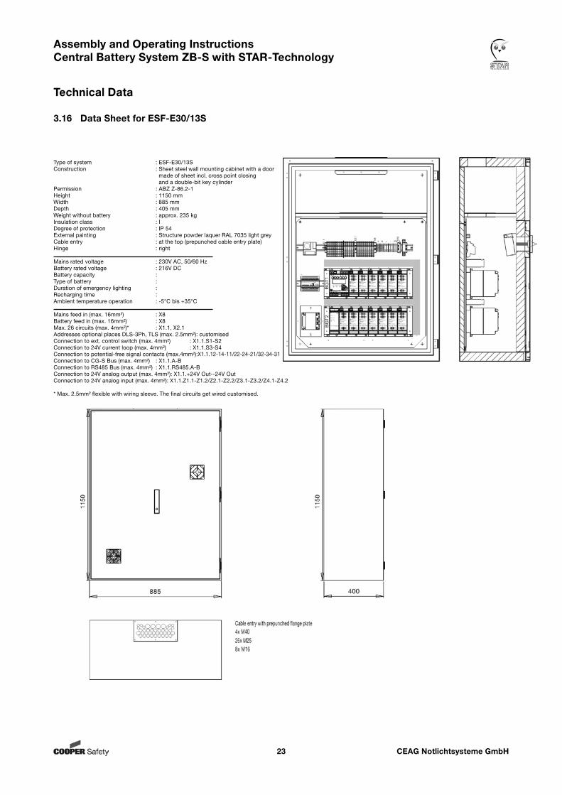
3.16 Data Sheet for ESF-E30/13S
Type of system : ESF-E30/13SConstruction : Sheet steel wall mounting cabinet with a door made of sheet incl. cross point closing and a double-bit key cylinderPermission : ABZ Z-86.2-1Height : 1150 mmWidth : 885 mmDepth : 405 mmWeight without battery : approx. 235 kgInsulation class : IDegree of protection : IP 54External painting : Structure powder laquer RAL 7035 light greyCable entry : at the top (prepunched cable entry plate)Hinge : right
Mains rated voltage : 230V AC, 50/60 HzBattery rated voltage : 216V DCBattery capacity : Type of battery : Duration of emergency lighting : Recharging time : Ambient temperature operation : -5°C bis +35°C
Mains feed in (max. 16mm²) : X8Battery feed in (max. 16mm²) : X8Max. 26 circuits (max. 4mm²)* : X1.1, X2.1Addresses optional places DLS-3Ph, TLS (max. 2.5mm²): customisedConnection to ext. control switch (max. 4mm²) : X1.1.S1-S2Connection to 24V current loop (max. 4mm²) : X1.1.S3-S4Connection to potential-free signal contacts (max.4mm²):X1.1.12-14-11/22-24-21/32-34-31Connection to CG-S Bus (max. 4mm²) : X1.1.A-BConnection to RS485 Bus (max. 4mm²) : X1.1.RS485.A-BConnection to 24V analog output (max. 4mm²): X1.1.+24V Out--24V OutConnection to 24V analog input (max. 4mm²): X1.1.Z1.1-Z1.2/Z2.1-Z2.2/Z3.1-Z3.2/Z4.1-Z4.2
* Max. 2.5mm² flexible with wiring sleeve. The final circuits get wired customised.
CEAG Notlichtsysteme GmbH24
Assembly and Operating Instructions Central Battery System ZB-S with STAR-Technology
Technical Data
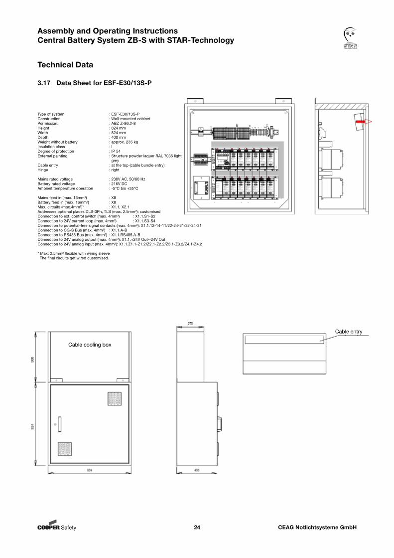
3.17 Data Sheet for ESF-E30/13S-P
Type of system : ESF-E30/13S-PConstruction : Wall-mounted cabinetPermission: : ABZ Z-86.2-8Height : 824 mmWidth : 824 mmDepth : 400 mmWeight without battery : approx. 235 kgInsulation class : IDegree of protection : IP 54External painting : Structure powder laquer RAL 7035 light greyCable entry : at the top (cable bundle entry)Hinge : right
Mains rated voltage : 230V AC, 50/60 HzBattery rated voltage : 216V DCAmbient temperature operation : -5°C bis +35°C
Mains feed in (max. 16mm²) : X8Battery feed in (max. 16mm²) : X8Max. circuits (max.4mm²)* : X1.1, X2.1Addresses optional places DLS-3Ph, TLS (max. 2.5mm²): customisedConnection to ext. control switch (max. 4mm²) : X1.1.S1-S2Connection to 24V current loop (max. 4mm²) : X1.1.S3-S4Connection to potential-free signal contacts (max. 4mm²): X1.1.12-14-11/22-24-21/32-34-31Connection to CG-S Bus (max. 4mm²) : X1.1.A-BConnection to RS485 Bus (max. 4mm²) : X1.1.RS485.A-BConnection to 24V analog output (max. 4mm²): X1.1.+24V Out--24V OutConnection to 24V analog input (max. 4mm²): X1.1.Z1.1-Z1.2/Z2.1-Z2.2/Z3.1-Z3.2/Z4.1-Z4.2
* Max. 2.5mm² flexible with wiring sleeve The final circuits get wired customised.
Cable cooling box
Cable entry
CEAG Notlichtsysteme GmbH25
Assembly and Operating Instructions Central Battery System ZB-S with STAR-Technology
Technical Data
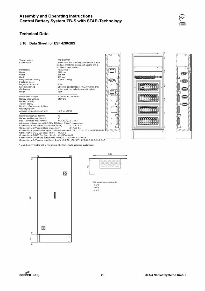
3.18 Data Sheet for ESF-E30/28S
Type of system : ESF-E30/28SConstruction : Sheet steel wall mounting cabinet with a door made of sheet incl. cross point closing and a double-bit key cylinderPermission: : ABZ Z-86.2-1Height : 2190 mmWidth : 885 mmDepth : 405 mmWeight without battery : approx. 390 kgInsulation class : IDegree of protection : IP 54External painting : Structure powder laquer RAL 7035 light greyCable entry : at the top (prepunched cable entry plate)Hinge : right
Mains rated voltage : 400/230V AC, 50/60 HzBattery rated voltage : 216V DCBattery capacity : Type of battery : Duration of emergency lighting : Recharging time : Ambient temperature operation : -5°C bis +35°C
Mains feed in (max. 16mm²) : X8Battery feed in (max. 16mm²) : X8Max. 56 circuits (max. 4mm²)* : X1.1, X2.1, X3.1, X4.1Addresses optional places DLS-3Ph, TLS (max. 2.5mm²): customisedConnection to ext. control switch (max. 4mm²) : X1.1.S1-S2Connection to 24V current loop (max. 4mm²) : X1.1.S3-S4Connection to potential-free signal contacts (max.4mm²): X1.1.12-14-11/22-24-21/32-34-31Connection to CG-S Bus (max. 4mm²) : X1.1.A-BConnection to RS485 Bus (max. 4mm²) : X1.1.RS485.A-BConnection to 24V analog output (max. 4mm²): X1.1.+24V Out--24V OutConnection to 24V analog input (max. 4mm²): X1.1.Z1.1-Z1.2/Z2.1-Z2.2/Z3.1-Z3.2/Z4.1-Z4.2
* Max. 2.5mm² flexible with wiring sleeve. The final circuits get wired customised.
CEAG Notlichtsysteme GmbH26
Assembly and Operating Instructions Central Battery System ZB-S with STAR-Technology
Technical Data
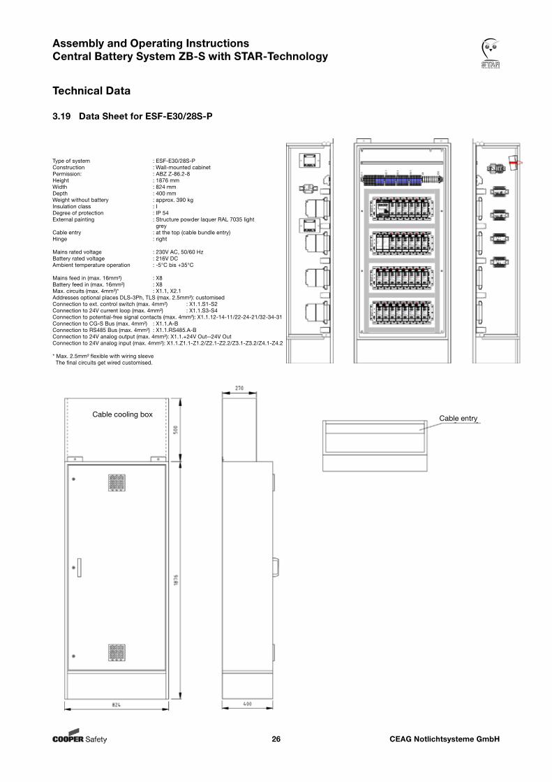
3.19 Data Sheet for ESF-E30/28S-P
Type of system : ESF-E30/28S-PConstruction : Wall-mounted cabinetPermission: : ABZ Z-86.2-8Height : 1876 mmWidth : 824 mmDepth : 400 mmWeight without battery : approx. 390 kgInsulation class : IDegree of protection : IP 54External painting : Structure powder laquer RAL 7035 light greyCable entry : at the top (cable bundle entry)Hinge : right
Mains rated voltage : 230V AC, 50/60 HzBattery rated voltage : 216V DCAmbient temperature operation : -5°C bis +35°C
Mains feed in (max. 16mm²) : X8Battery feed in (max. 16mm²) : X8Max. circuits (max. 4mm²)* : X1.1, X2.1Addresses optional places DLS-3Ph, TLS (max. 2.5mm²): customisedConnection to ext. control switch (max. 4mm²) : X1.1.S1-S2Connection to 24V current loop (max. 4mm²) : X1.1.S3-S4Connection to potential-free signal contacts (max. 4mm²): X1.1.12-14-11/22-24-21/32-34-31Connection to CG-S Bus (max. 4mm²) : X1.1.A-BConnection to RS485 Bus (max. 4mm²) : X1.1.RS485.A-BConnection to 24V analog output (max. 4mm²): X1.1.+24V Out--24V OutConnection to 24V analog input (max. 4mm²): X1.1.Z1.1-Z1.2/Z2.1-Z2.2/Z3.1-Z3.2/Z4.1-Z4.2
* Max. 2.5mm² flexible with wiring sleeve The final circuits get wired customised.
Cable cooling box Cable entry
CEAG Notlichtsysteme GmbH27
Assembly and Operating Instructions Central Battery System ZB-S with STAR-Technology
Technical Data
CEAG Notlichtsysteme GmbH28
Assembly and Operating Instructions Central Battery System ZB-S with STAR-Technology
Construction and Function
4. Construction and Function
4.1 Example of Control Cabinet-Construction (ZB-S/26)
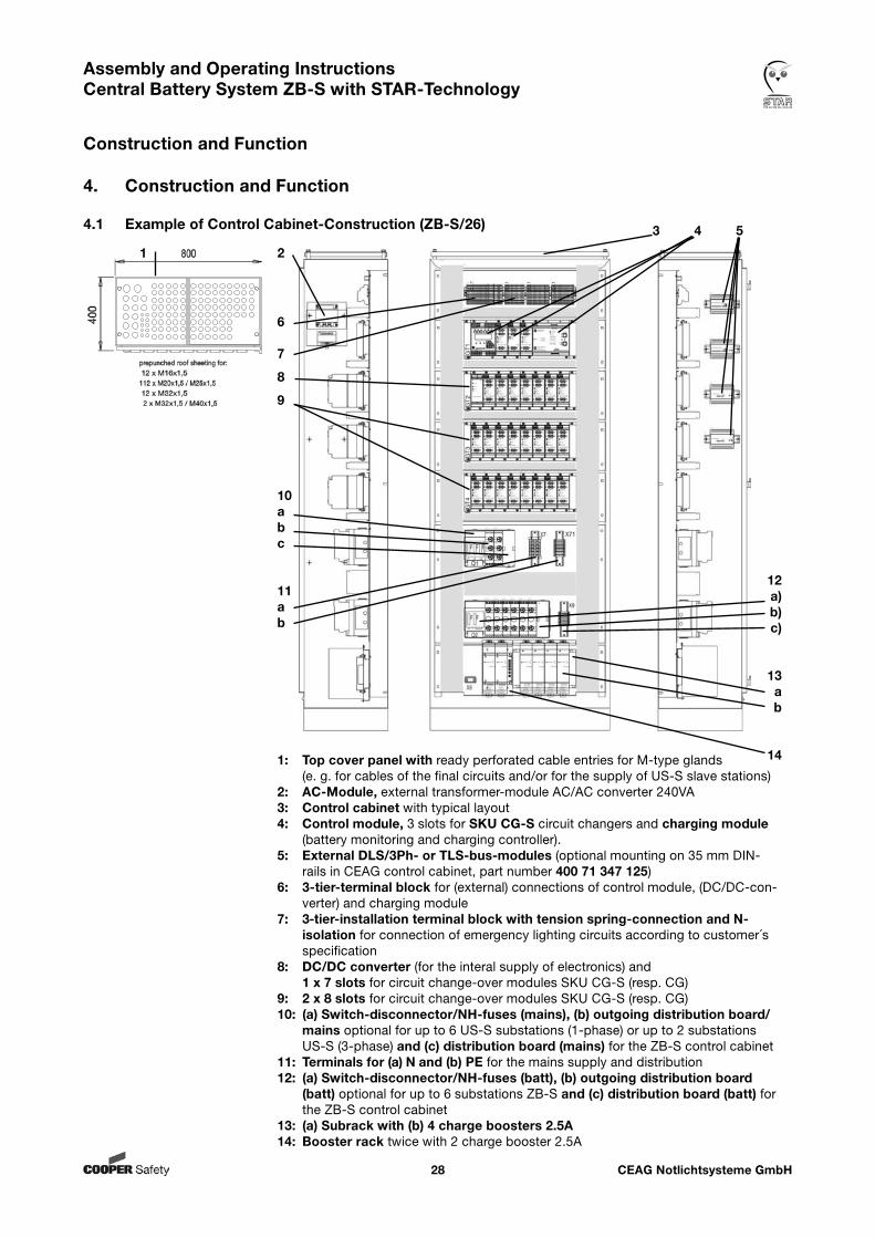
1: Top cover panel with ready perforated cable entries for M-type glands (e. g. for cables of the final circuits and/or for the supply of US-S slave stations)
2: AC-Module, external transformer-module AC/AC converter 240VA3: Control cabinet with typical layout4: Control module, 3 slots for SKU CG-S circuit changers and charging module
(battery monitoring and charging controller).5: External DLS/3Ph- or TLS-bus-modules (optional mounting on 35 mm DIN-
rails in CEAG control cabinet, part number 400 71 347 125)6: 3-tier-terminal block for (external) connections of control module, (DC/DC-con-
verter) and charging module7: 3-tier-installation terminal block with tension spring-connection and N-
isolation for connection of emergency lighting circuits according to customer´s specification
8: DC/DC converter (for the interal supply of electronics) and 1 x 7 slots for circuit change-over modules SKU CG-S (resp. CG)9: 2 x 8 slots for circuit change-over modules SKU CG-S (resp. CG)10: (a) Switch-disconnector/NH-fuses (mains), (b) outgoing distribution board/
mains optional for up to 6 US-S substations (1-phase) or up to 2 substations US-S (3-phase) and (c) distribution board (mains) for the ZB-S control cabinet
11: Terminals for (a) N and (b) PE for the mains supply and distribution12: (a) Switch-disconnector/NH-fuses (batt), (b) outgoing distribution board
(batt) optional for up to 6 substations ZB-S and (c) distribution board (batt) for the ZB-S control cabinet
13: (a) Subrack with (b) 4 charge boosters 2.5A 14: Booster rack twice with 2 charge booster 2.5A
6
7
8
9
10abc
11ab
3 4 5
12a)b)c)
13ab
14
1 2
CEAG Notlichtsysteme GmbH29
Assembly and Operating Instructions Central Battery System ZB-S with STAR-Technology
Construction and Function
4.2 Product Description The Central Battery System ZB-S with the new START technology is a logical successor to the wellproven Cen- tral Battery System ZB 96. STAR stands for: SWITCHING TECHNOLOGY ADVANCED REVISION The main benefits of this technology include the fact that within a final circuit, the switching modes - Non-maintained light (Emergency lighting is switched on when the main lighting fails or when a function test or operating duration test is initiated manually or automatically) - Maintained light and (Emergency lighting is always on) - Switched maintained light (as non-maintained light with emergency lighting controlled by switch queries, e. g. from external DLS-modules) can be implemented in hybrid mode for each emergency luminaire. each safety and EXIT luminaire can be programmed without an extra data cable , the switching modes can be later modified without the need to interfere in the existing luminaire installation.
The functions of the emergency luminaires are defined with a user-friendly parameter setup system. The use of CG-S type ballasts/modules is a requirement. All settings are stored in a nonvolatile memory and so are not lost even in a total shutdown situation (230V mains and battery supply). Parameter settings and the names of circuits, luminaires and DLS/TLS-modules as well as test log entries can also be stored on a memory card. As well as archiving, this also allows (optional) external parameter setting and transfer to control modules of the ZB-S system.
Maintenance-free and closed batteries according to EN 60896-2 supply the power needed to operate the emer- gency lighting if the 230V mains supply should fail. During normal operation, the ZB-S system monitors the char- ge status of the batteries and charges them up gently if required.
The system ZB-S is designed and manufactured in compliance with the following EC directives: Low-voltage Directive 2006/95/EG Directive 2004/108/EG on electromagnetic compatibility National (DIN-), European (EN-) and international (IEC-) standards which the system complies will be found in the system´s CE Certificate of Conformity.
4.3 Operation Modes Different system configurations are used depending on the requirements of the site. These standardised configu- rations have names like ZB-S/26 or ZB-S/18 for operation with up to 26 or 18 SKU CG-S modules (resp CG) with 80 or 68 circuit terminals. Up to 6 substa- tions US-S can be supplied with battery or mains power (up to 6 substations 1-phase, up to 2 substations 3-phase). ZB-S/LAD These are designed as charging and monitoring units for the mains and battery supply to a large number of substa tions US-S. Up to 4 circuits can be supplied and controlled. ZB-S/10C, ZB-S/10C6, ZB-S/18C6, ZB-S/26C6, ZB-S/10C3, ZB-S/18C3, ZB-S 2C3 for operation with up to 10 or 18 SKU CG-S modules (resp. CG) with 40, 56 and 60 circuit terminals. US-S/36, US-S/28, US-S/21, US-S/13, US-S/5 for operation with up to 5, 13, 21, 28 or 36 SKU CG-S modules(resp. CG) with 20, 24, 26, 52 and 80 circuit terminals. These substations do not have the charging technology of the connected battery standby supply; the battery and mains supply is provided by the ZB-S system. ESF-30/13S, ESF-E30/28S, ESF-E30/13S-P or ESF-E30/28S-P Mains distribution board with circuit integrity of 30 minutes in case of fire for operation with up to 13 or 28 SKU CG-S modules (resp. CG) with 26 or 56 circuit terminals.
CEAG Notlichtsysteme GmbH30
Assembly and Operating Instructions Central Battery System ZB-S with STAR-Technology
Construction and Function
All devices and substations are constructed modularly. The technologies of charging, changing-over and of monitoring form a unit working undependent from each other, so that interactions can be excluded. Due to the modular construction and the pre-configured modules a flexible and high quality handling is ensured. The objective of the emergency lighting system is to supply the connected emergency luminaires when the main lightings fails. Another important function of the system is to secure the function standby of all connected emer- gency and EXIT luminaires by an automatic monitoring.
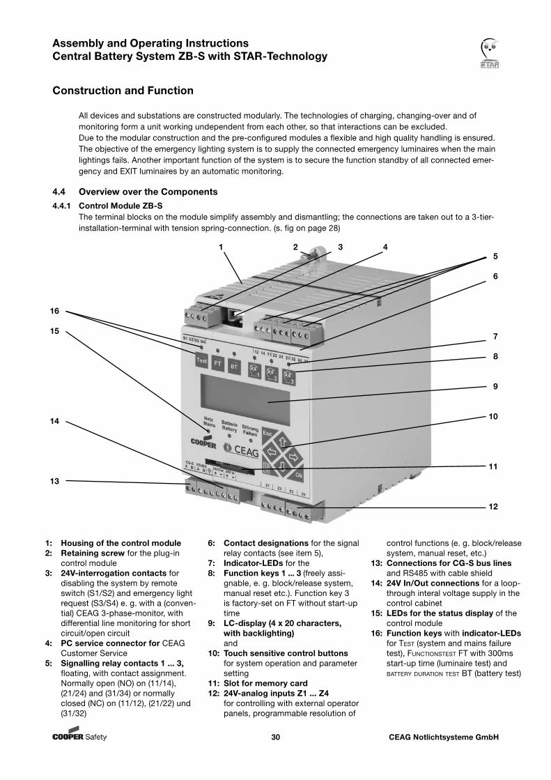
4.4 Overview over the Components4.4.1 Control Module ZB-S The terminal blocks on the module simplify assembly and dismantling; the connections are taken out to a 3-tier- installation-terminal with tension spring-connection. (s. fig on page 28)
1: Housing of the control module2: Retaining screw for the plug-in
control module3: 24V-interrogation contacts for
disabling the system by remote switch (S1/S2) and emergency light request (S3/S4) e. g. with a (conven-tial) CEAG 3-phase-monitor, with differential line monitoring for short circuit/open circuit
4: PC service connector for CEAG Customer Service
5: Signalling relay contacts 1 ... 3, floating, with contact assignment. Normally open (NO) on (11/14), (21/24) and (31/34) or normally closed (NC) on (11/12), (21/22) und (31/32)
6: Contact designations for the signal relay contacts (see item 5),
7: Indicator-LEDs for the8: Function keys 1 ... 3 (freely assi-
gnable, e. g. block/release system, manual reset etc.). Function key 3 is factory-set on FT without start-up time
9: LC-display (4 x 20 characters, with backlighting) and
10: Touch sensitive control buttons for system operation and parameter setting
11: Slot for memory card12: 24V-analog inputs Z1 ... Z4
for controlling with external operator panels, programmable resolution of
control functions (e. g. block/release system, manual reset, etc.)
13: Connections for CG-S bus lines and RS485 with cable shield
14: 24V In/Out connections for a loop-through interal voltage supply in the control cabinet
15: LEDs for the status display of the control module
16: Function keys with indicator-LEDs for TesT (system and mains failure test), FuncTionsTesT FT with 300ms start-up time (luminaire test) and baTTery duraTion TesT BT (battery test)
16
15
14
13
5
6
7
8
9
10
11
12
1 2 3 4
CEAG Notlichtsysteme GmbH31
Assembly and Operating Instructions Central Battery System ZB-S with STAR-Technology
Construction and Function
Free programmable control with a nonvolatile programm memory for programming and user-specific parameter setting.
Internal log book recording the ST-S control module stores the test log (max. 360,000 entries) according to the specifications of DIN VDE 0108. An external reporting with a memory card is possible.
Operation Directly on the device ST-S controller using - sealed keypad and - LC display (4 x 20 characters, with adjustable backlighting) (Compare chapter 9). Local switch operation of combined main/emergency lighting can be achieved with DLS/3Ph and TLS bus modules. Service connector for CEAG service engineers at the front of the device Configuration At the front of the device using keys and LC-Display. There are considerable possiblities for userdefined settings via a menu controlled parameterisation (compare chapter 9). Via data exchange via memory card, e. g. for a transfer of the settings between similar cabinets. External configuration of the control module is possible with – a usual personal computer (PC) and – CEAG-software for the system ZB-S.
Communication and control Data exchange with installed CG-S components and CG-S-compatible ballasts (using the cables of the final circuits) RS485 bus allows data to be exchanged with external modules (DLS/3PH-bus-modules or TLS-bus-modules, (RS485 port on the control module, up to 25 devices). External CG-S bus port (CEAG bus protocol) for data exchange with BMS. Data Exchange and Storage Internal: with non-volatile memory in the ST-S control module External: with a memory card reader, type of the uses memory card: SD-card / CEAG part no. 400 71 347 911 (preprogrammed) SD-adapter enables data exchange and saving with usual PC under the CEAG-Software for the system ZB-S
CEAG Notlichtsysteme GmbH32
Assembly and Operating Instructions Central Battery System ZB-S with STAR-Technology
Construction and Function
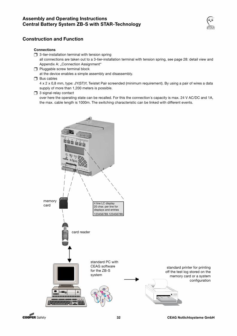
Connections 3-tier-installation terminal with tension spring all connections are taken out to a 3-tier-installation terminal with tension spring, see page 28: detail view and Appendix A: „Connection Assignment“ Pluggable screw terminal block at the device enables a simple assembly and disassembly. Bus cables 4 x 2 x 0,8 mm, type: JY(ST)Y, Twistet Pair screended (minimum requirement). By using a pair of wires a data supply of more than 1,200 meters is possible. 3 signal-relay contact over here the operating state can be recalled. For this the connection´s capacity is max. 24 V AC/DC and 1A, the max. cable length is 1000m. The switching characteristic can be linked with different events.
standard printer for printing off the test log stored on the
memory card or a system configuration
card reader
4 line LC display20 char. per line for displays and entries
123456789.123456789.
memorycard
standard PC with CEAG softwarefor the ZB-S system
CEAG Notlichtsysteme GmbH33
Assembly and Operating Instructions Central Battery System ZB-S with STAR-Technology
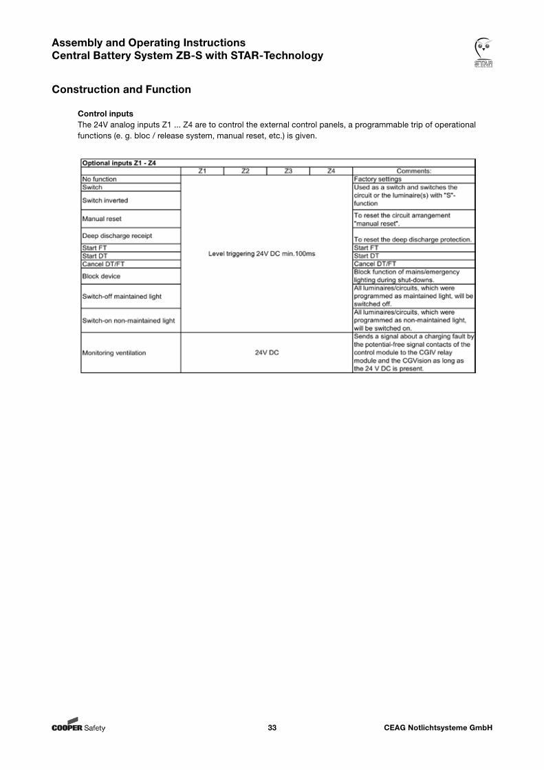
Construction and Function
Control inputs The 24V analog inputs Z1 ... Z4 are to control the external control panels, a programmable trip of operational functions (e. g. bloc / release system, manual reset, etc.) is given.
CEAG Notlichtsysteme GmbH34
Assembly and Operating InstructionsCentral Battery System ZB-S with STAR-Technology
Construction and Function
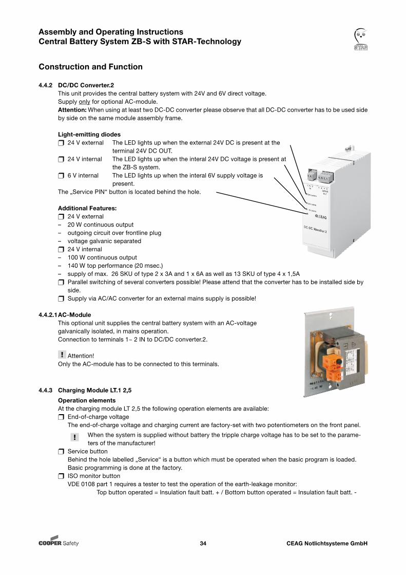
4.4.2 DC/DC Converter.2 This unit provides the central battery system with 24V and 6V direct voltage. Supply only for optional AC-module. Attention: When using at least two DC-DC converter please observe that all DC-DC converter has to be used side by side on the same module assembly frame.
Light-emitting diodes 24 V external The LED lights up when the external 24V DC is present at the terminal 24V DC OUT. 24 V internal The LED lights up when the interal 24V DC voltage is present at the ZB-S system. 6 V internal The LED lights up when the interal 6V supply voltage is present. The „Service PIN“ button is located behind the hole.
Additional Features: 24 V external – 20 W continuous output – outgoing circuit over frontline plug – voltage galvanic separated 24 V internal – 100 W continuous output – 140 W top performance (20 msec.) – supply of max. 26 SKU of type 2 x 3A and 1 x 6A as well as 13 SKU of type 4 x 1,5A Parallel switching of several converters possible! Please attend that the converter has to be installed side by side. Supply via AC/AC converter for an external mains supply is possible!
4.4.2.1 AC-Module This optional unit supplies the central battery system with an AC-voltage galvanically isolated, in mains operation. Connection to terminals 1~ 2 IN to DC/DC converter.2.
Attention! Only the AC-module has to be connected to this terminals.
4.4.3 Charging Module LT.1 2,5
Operation elements At the charging module LT 2,5 the following operation elements are available: End-of-charge voltage The end-of-charge voltage and charging current are factory-set with two potentiometers on the front panel.
When the system is supplied without battery the tripple charge voltage has to be set to the parame- ters of the manufacturer! Service button Behind the hole labelled „Service“ is a button which must be operated when the basic program is loaded. Basic programming is done at the factory. ISO monitor button VDE 0108 part 1 requires a tester to test the operation of the earth-leakage monitor: Top button operated = Insulation fault batt. + / Bottom button operated = Insulation fault batt. -
CEAG Notlichtsysteme GmbH35
Assembly and Operating Instructions Central Battery System ZB-S with STAR-Technology
Construction and Function
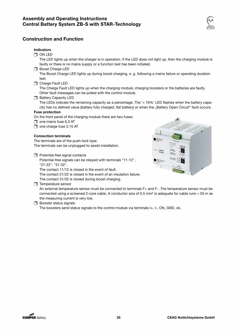
Indicators ON LED The LED lights up when the charger is in operation. If the LED does not light up, then the charging module is faulty or there is no mains supply or a function test has been initiated. Boost Charge LED The Boost Charge LED lights up during boost charging, e. g. following a mains failure or operating duration test. Charge Fault LED The Charge Fault LED lights up when the charging module, charging boosters or the batteries are faulty. Other fault messages can be polled with the control module. Battery Capacity LED The LEDs indicate the remaining capacity as a percentage. The ‘> 10%’ LED flashes when the battery capa- city has no defined value (battery fully charged, flat battery) or when the „Battery Open Circuit“ fault occurs. Fuse protection On the front panel of the charging module there are two fuses: one mains fuse 6.3 AT one charge fuse 3.15 AT
Connection terminals The terminals are of the push-lock type. The terminals can be unplugged to assist installation.
Potential-free signal contacts Potential-free signals can be relayed with terminals "11-12", "21-22", "31-32". The contact 11/12 is closed in the event of fault. The contact 21/22 is closed in the event of an insulation failure. The contact 31/32 is closed during boost charging. Temperature sensor An external temperature sensor must be connected to terminals F+ and F-. The temperature sensor must be connected using a screened 2-core cable. A conductor size of 0.5 mm² is adequate for cable runs < 50 m as the measuring current is very low. Booster status signals The boosters send status signals to the control module via terminals I+, I-, ON, GND, ok.
CEAG Notlichtsysteme GmbH36
Assembly and Operating Instructions Central Battery System ZB-S with STAR-Technology
Construction and Function
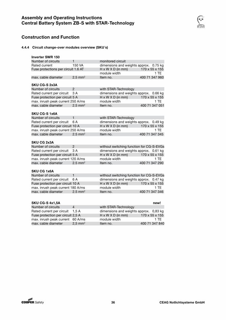
SKU CG-S 4x1,5A new!Number of circuits 4 with STAR-TechnologyRated current per circuit 1,5 A dimensions and weights approx. 0,83 kgFuse protection per circuit 2,5 A H x W X D (in mm) 170 x 55 x 155max. inrush peak current 60 A/ms module width 1 TEmax. cable diameter 2,5 mm2 Item no. 400 71 347 840
Inverter SWR 150 Number of circuits 1 monitored circuitRated current 150 VA dimensions and weights approx. 0.75 kgFuse protections per circuit 1.6 AT H x W X D (in mm) 170 x 55 x 155 module width 1 TE max. cable diameter 2.5 mm2 Item no. 400 71 347 960
SKU CG-S 2x3A Number of circuits 2 with STAR-TechnologyRated current per circuit 3 A dimensions and weights approx. 0.66 kgFuse protection per circuit 5 A H x W X D (in mm) 170 x 55 x 155max. inrush peak current 250 A/ms module width 1 TEmax. cable diameter 2.5 mm2 Item no. 400 71 347 051 SKU CG-S 1x6A Number of circuits 1 with STAR-TechnologyRated current per circuit 6 A dimensions and weights approx. 0.49 kgFuse protection per circuit 10 A H x W X D (in mm) 170 x 55 x 155max. inrush peak current 250 A/ms module width 1 TEmax. cable diameter 2.5 mm2 Item no. 400 71 347 345 SKU CG 2x3A Number of circuits 2 without switching function for CG-S-EVGsRated current per circuit 3 A dimensions and weights approx. 0.61 kgFuse protection per circuit 5 A H x W X D (in mm) 170 x 55 x 155max. inrush peak current 120 A/ms module width 1 TEmax. cable diameter 2.5 mm2 Item no. 400 71 347 290 SKU CG 1x6A Number of circuits 1 without switching function for CG-S-EVGsRated current per circuit 6 A dimensions and weights approx. 0.47 kgFuse protection per circuit 10 A H x W X D (in mm) 170 x 55 x 155max. inrush peak current 180 A/ms module width 1 TEmax. cable diameter 2.5 mm2 Item no. 400 71 347 346
4.4.4 Circuit change-over modules overview (SKU´s)
CEAG Notlichtsysteme GmbH37
Assembly and Operating Instructions Central Battery System ZB-S with STAR-Technology
Construction and Function
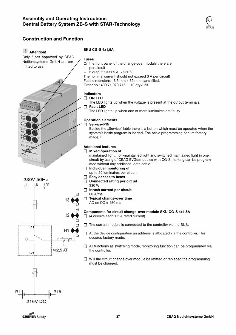
SKU CG-S 4x1,5A
FusesOn the front panel of the change-over module there are – per circuit – 3 output fuses 5 AT / 250 V.The nominal current should not exceed 3 A per circuit! Fuse dimensions: 6.3 mm x 32 mm, sand filled. Order no.: 400 71 070 716 10 qty./unit
Indicators ON LED The LED lights up when the voltage is present at the output terminals. Fault LED The LED lights up when one or more luminaires are faulty.
Operation elements Service-PIN Beside the „Service“ lable there is a button which must be operated when the system´s basic program is loaded. The basic programming occurs factory made.1)
Additional features Mixed operation of maintained light, non-maintained light and switched maintained light in one
circuit by using of CEAG EVGs/modules with CG-S marking can be program-med without any additional data cable.
Individual monitoring of up to 20 luminaires per circuit.
Easy access to fuses Connected rating per circuit 330 W Inrush current per circuit
60 A/ms Typical change-over time
AC on DC = 450 ms
Components for circuit change-over module SKU CG-S 4x1,5A (4 circuits each 1,5 A rated current)
The current module is connected to the controller via the BUS.
At the device configuration an address is allocated via the controller. This occures factory made.
All functions as switching mode, monitoring function can be programmed via the controller.
Will the circuit change over module be refitted or replaced the programming must be changed.
Attention!Only fuses approved by CEAG Notlichtsysteme GmbH are per-mitted to use.
CEAG Notlichtsysteme GmbH38
Assembly and Operating Instructions Central Battery System ZB-S with STAR-Technology
Construction and Function
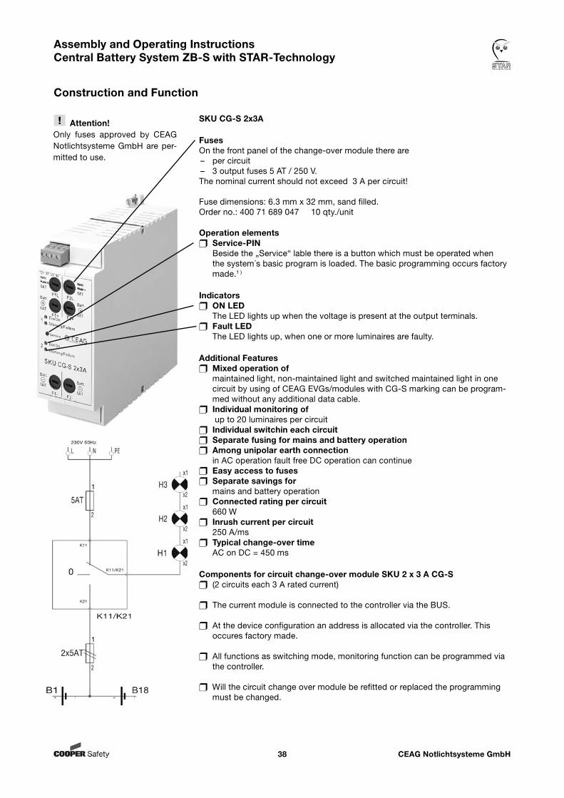
SKU CG-S 2x3A
FusesOn the front panel of the change-over module there are– per circuit – 3 output fuses 5 AT / 250 V.The nominal current should not exceed 3 A per circuit!
Fuse dimensions: 6.3 mm x 32 mm, sand filled.Order no.: 400 71 689 047 10 qty./unit
Operation elements Service-PIN Beside the „Service“ lable there is a button which must be operated when the system´s basic program is loaded. The basic programming occurs factory made.1 )
Indicators ON LED The LED lights up when the voltage is present at the output terminals. Fault LED The LED lights up, when one or more luminaires are faulty.
Additional Features Mixed operation of maintained light, non-maintained light and switched maintained light in one
circuit by using of CEAG EVGs/modules with CG-S marking can be program-med without any additional data cable.
Individual monitoring of up to 20 luminaires per circuit
Individual switchin each circuit Separate fusing for mains and battery operation Among unipolar earth connection
in AC operation fault free DC operation can continue Easy access to fuses Separate savings for
mains and battery operation Connected rating per circuit 660 W Inrush current per circuit
250 A/ms Typical change-over time
AC on DC = 450 ms
Components for circuit change-over module SKU 2 x 3 A CG-S (2 circuits each 3 A rated current)
The current module is connected to the controller via the BUS.
At the device configuration an address is allocated via the controller. This occures factory made.
All functions as switching mode, monitoring function can be programmed via the controller.
Will the circuit change over module be refitted or replaced the programming must be changed.
Attention!Only fuses approved by CEAG Notlichtsysteme GmbH are per-mitted to use.
CEAG Notlichtsysteme GmbH39
Assembly and Operating Instructions Central Battery System ZB-S with STAR-Technology
Construction and Function
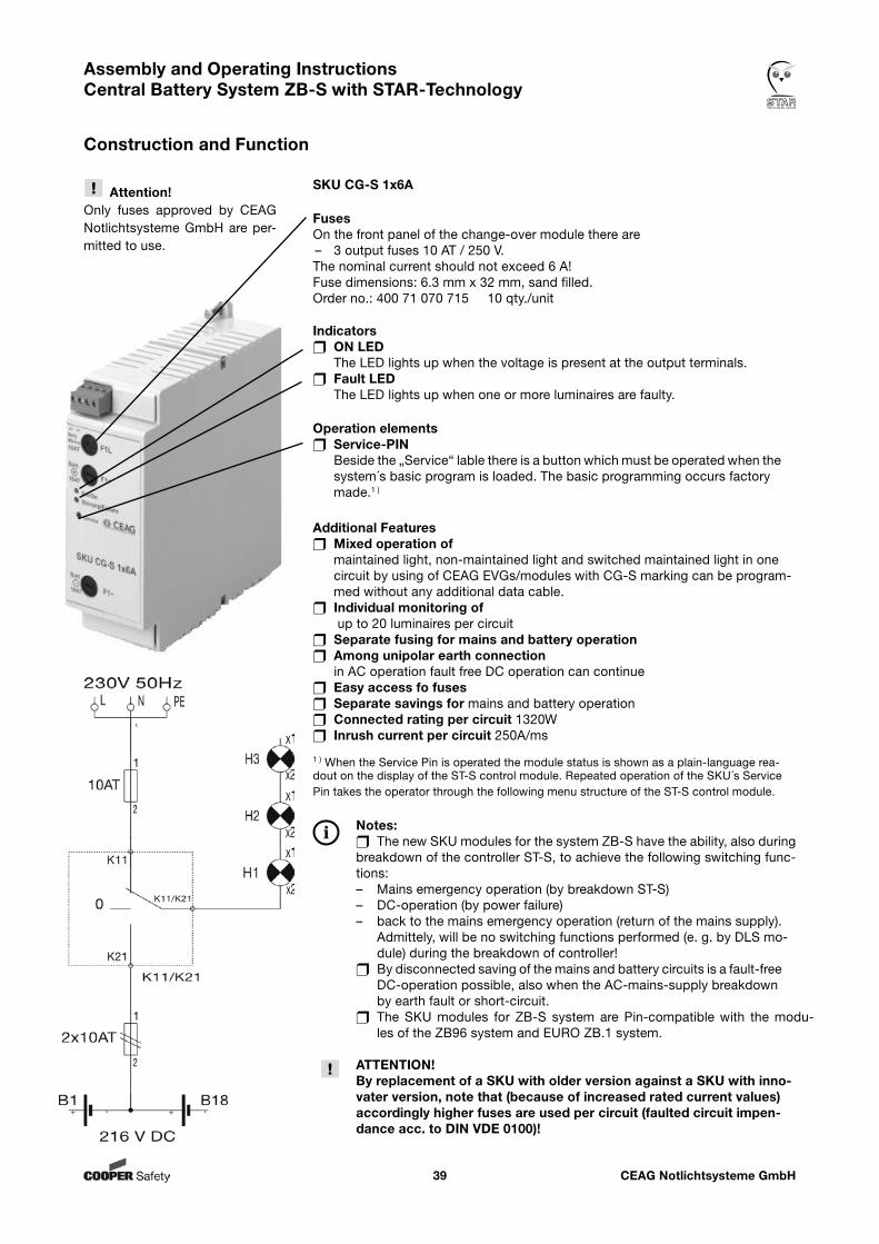
1 ) When the Service Pin is operated the module status is shown as a plain-language rea-dout on the display of the ST-S control module. Repeated operation of the SKU´s Service Pin takes the operator through the following menu structure of the ST-S control module.
SKU CG-S 1x6A
FusesOn the front panel of the change-over module there are – 3 output fuses 10 AT / 250 V.The nominal current should not exceed 6 A!Fuse dimensions: 6.3 mm x 32 mm, sand filled. Order no.: 400 71 070 715 10 qty./unit
Indicators ON LED The LED lights up when the voltage is present at the output terminals. Fault LED The LED lights up when one or more luminaires are faulty.
Operation elements Service-PIN Beside the „Service“ lable there is a button which must be operated when the system´s basic program is loaded. The basic programming occurs factory made.1 )
Additional Features Mixed operation of maintained light, non-maintained light and switched maintained light in one
circuit by using of CEAG EVGs/modules with CG-S marking can be program-med without any additional data cable.
Individual monitoring of up to 20 luminaires per circuit
Separate fusing for mains and battery operation Among unipolar earth connection
in AC operation fault free DC operation can continue Easy access fo fuses Separate savings for mains and battery operation Connected rating per circuit 1320W Inrush current per circuit 250A/ms
Notes: The new SKU modules for the system ZB-S have the ability, also during breakdown of the controller ST-S, to achieve the following switching func-tions:– Mains emergency operation (by breakdown ST-S)– DC-operation (by power failure)– back to the mains emergency operation (return of the mains supply).
Admittely, will be no switching functions performed (e. g. by DLS mo-dule) during the breakdown of controller!
By disconnected saving of the mains and battery circuits is a fault-free DC-operation possible, also when the AC-mains-supply breakdown by earth fault or short-circuit. The SKU modules for ZB-S system are Pin-compatible with the modu- les of the ZB96 system and EURO ZB.1 system.
ATTENTION!By replacement of a SKU with older version against a SKU with inno-vater version, note that (because of increased rated current values) accordingly higher fuses are used per circuit (faulted circuit impen-dance acc. to DIN VDE 0100)!
Attention!Only fuses approved by CEAG Notlichtsysteme GmbH are per-mitted to use.
CEAG Notlichtsysteme GmbH40
Assembly and Operating Instructions Central Battery System ZB-S with STAR-Technology
Construction and Function
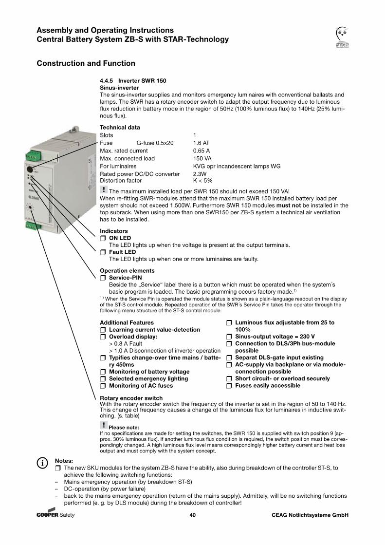
4.4.5 Inverter SWR 150Sinus-inverterThe sinus-inverter supplies and monitors emergency luminaires with conventional ballasts and lamps. The SWR has a rotary encoder switch to adapt the output frequency due to luminous flux reduction in battery mode in the region of 50Hz (100% luminous flux) to 140Hz (25% lumi-nous flux).
Technical dataSlots 1Fuse G-fuse 0.5x20 1.6 ATMax. rated current 0.65 AMax. connected load 150 VAFor luminaires KVG opr incandescent lamps WGRated power DC/DC converter 2.3WDistortion factor K < 5%
The maximum installed load per SWR 150 should not exceed 150 VA!When re-fitting SWR-modules attend that the maximum SWR 150 installed battery load per system should not exceed 1,500W. Furthermore SWR 150 modules must not be installed in the top subrack. When using more than one SWR150 per ZB-S system a technical air ventilation has to be installed.
Indicators ON LED The LED lights up when the voltage is present at the output terminals. Fault LED The LED lights up when one or more luminaires are faulty.
Operation elements Service-PIN Beside the „Service“ label there is a button which must be operated when the system´s basic program is loaded. The basic programming occurs factory made.1)
1 ) When the Service Pin is operated the module status is shown as a plain-language readout on the display of the ST-S control module. Repeated operation of the SWR´s Service Pin takes the operator through the following menu structure of the ST-S control module.
Rotary encoder switchWith the rotary encoder switch the frequency of the inverter is set in the region of 50 to 140 Hz. This change of frequency causes a change of the luminous flux for luminaires in inductive swit-ching. (s. table) Please note:If no specifications are made for setting the switches, the SWR 150 is supplied with switch position 9 (ap-prox. 30% luminous flux). If another luminous flux condition is required, the switch position must be corres-pondingly changed. A high luminous flux level means correspondingly higher battery current and heat loss output and must comply with the system concept.
Notes: The new SKU modules for the system ZB-S have the ability, also during breakdown of the controller ST-S, to achieve the following switching functions:– Mains emergency operation (by breakdown ST-S)– DC-operation (by power failure)– back to the mains emergency operation (return of the mains supply). Admittely, will be no switching functions
performed (e. g. by DLS module) during the breakdown of controller!
Additional Features Learning current value-detection Overload display:
> 0.8 A Fault > 1.0 A Disconnection of inverter operation Typifies change-over time mains / batte-
ry 450ms Monitoring of battery voltage Selected emergency lighting Monitoring of AC fuses
Luminous flux adjustable from 25 to 100%
Sinus-output voltage = 230 V Connection to DLS/3Ph bus-module
possible Separat DLS-gate input existing AC-supply via backplane or via module-
connection possible Short circuit- or overload securely Fuses easily accessible
CEAG Notlichtsysteme GmbH41
Assembly and Operating Instructions Central Battery System ZB-S with STAR-Technology
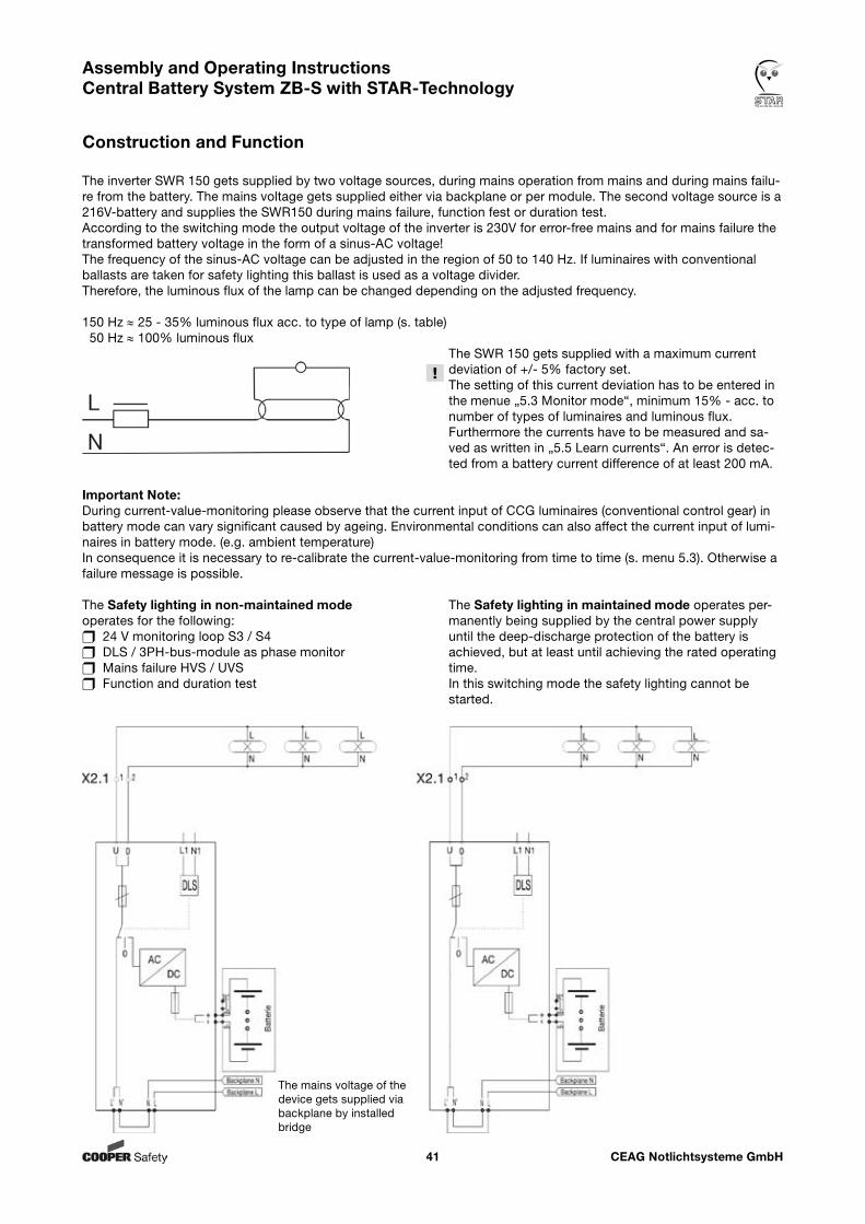
Construction and Function
The inverter SWR 150 gets supplied by two voltage sources, during mains operation from mains and during mains failu-re from the battery. The mains voltage gets supplied either via backplane or per module. The second voltage source is a 216V-battery and supplies the SWR150 during mains failure, function fest or duration test.According to the switching mode the output voltage of the inverter is 230V for error-free mains and for mains failure the transformed battery voltage in the form of a sinus-AC voltage!The frequency of the sinus-AC voltage can be adjusted in the region of 50 to 140 Hz. If luminaires with conventional ballasts are taken for safety lighting this ballast is used as a voltage divider.Therefore, the luminous flux of the lamp can be changed depending on the adjusted frequency.
150 Hz ≈ 25 - 35% luminous flux acc. to type of lamp (s. table) 50 Hz ≈ 100% luminous flux The SWR 150 gets supplied with a maximum current deviation of +/- 5% factory set. The setting of this current deviation has to be entered in the menue „5.3 Monitor mode“, minimum 15% - acc. to number of types of luminaires and luminous flux. Furthermore the currents have to be measured and sa- ved as written in „5.5 Learn currents“. An error is detec- ted from a battery current difference of at least 200 mA.
Important Note:During current-value-monitoring please observe that the current input of CCG luminaires (conventional control gear) in battery mode can vary significant caused by ageing. Environmental conditions can also affect the current input of lumi-naires in battery mode. (e.g. ambient temperature)In consequence it is necessary to re-calibrate the current-value-monitoring from time to time (s. menu 5.3). Otherwise a failure message is possible.
The Safety lighting in non-maintained mode The Safety lighting in maintained mode operates per-operates for the following: manently being supplied by the central power supply 24 V monitoring loop S3 / S4 until the deep-discharge protection of the battery is DLS / 3PH-bus-module as phase monitor achieved, but at least until achieving the rated operating Mains failure HVS / UVS time. Function and duration test In this switching mode the safety lighting cannot be started.
The mains voltage of the device gets supplied via backplane by installed bridge
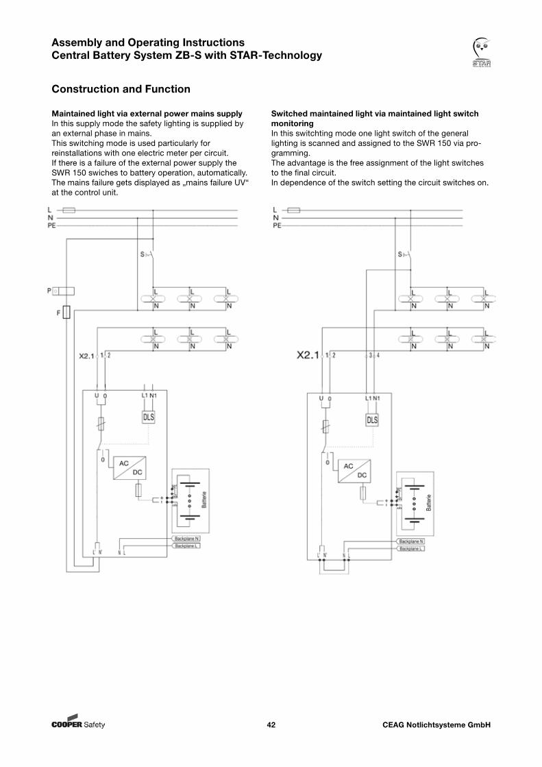
CEAG Notlichtsysteme GmbH42
Assembly and Operating Instructions Central Battery System ZB-S with STAR-Technology
Construction and Function
Maintained light via external power mains supply Switched maintained light via maintained light switchIn this supply mode the safety lighting is supplied by monitoringan external phase in mains. In this switchting mode one light switch of the general This switching mode is used particularly for lighting is scanned and assigned to the SWR 150 via pro-reinstallations with one electric meter per circuit. gramming.If there is a failure of the external power supply the The advantage is the free assignment of the light switches SWR 150 swiches to battery operation, automatically. to the final circuit.The mains failure gets displayed as „mains failure UV“ In dependence of the switch setting the circuit switches on.at the control unit.
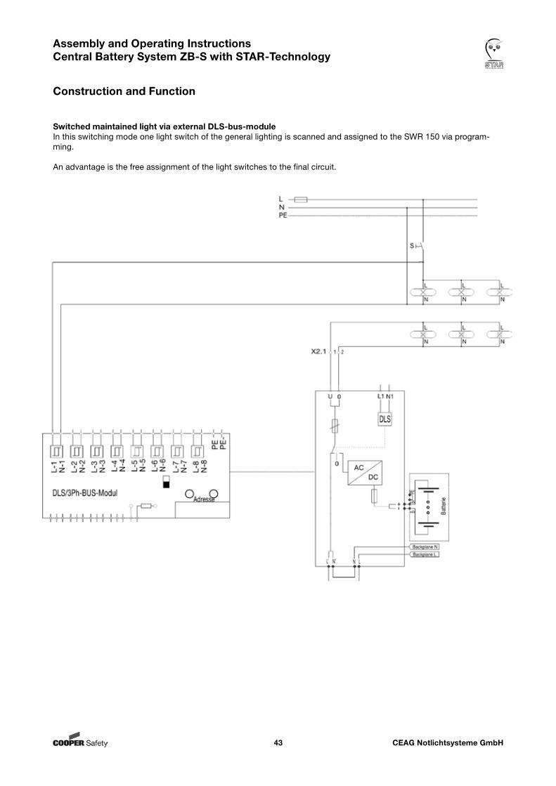
CEAG Notlichtsysteme GmbH43
Assembly and Operating Instructions Central Battery System ZB-S with STAR-Technology
Construction and Function
Switched maintained light via external DLS-bus-moduleIn this switching mode one light switch of the general lighting is scanned and assigned to the SWR 150 via program-ming.
An advantage is the free assignment of the light switches to the final circuit.
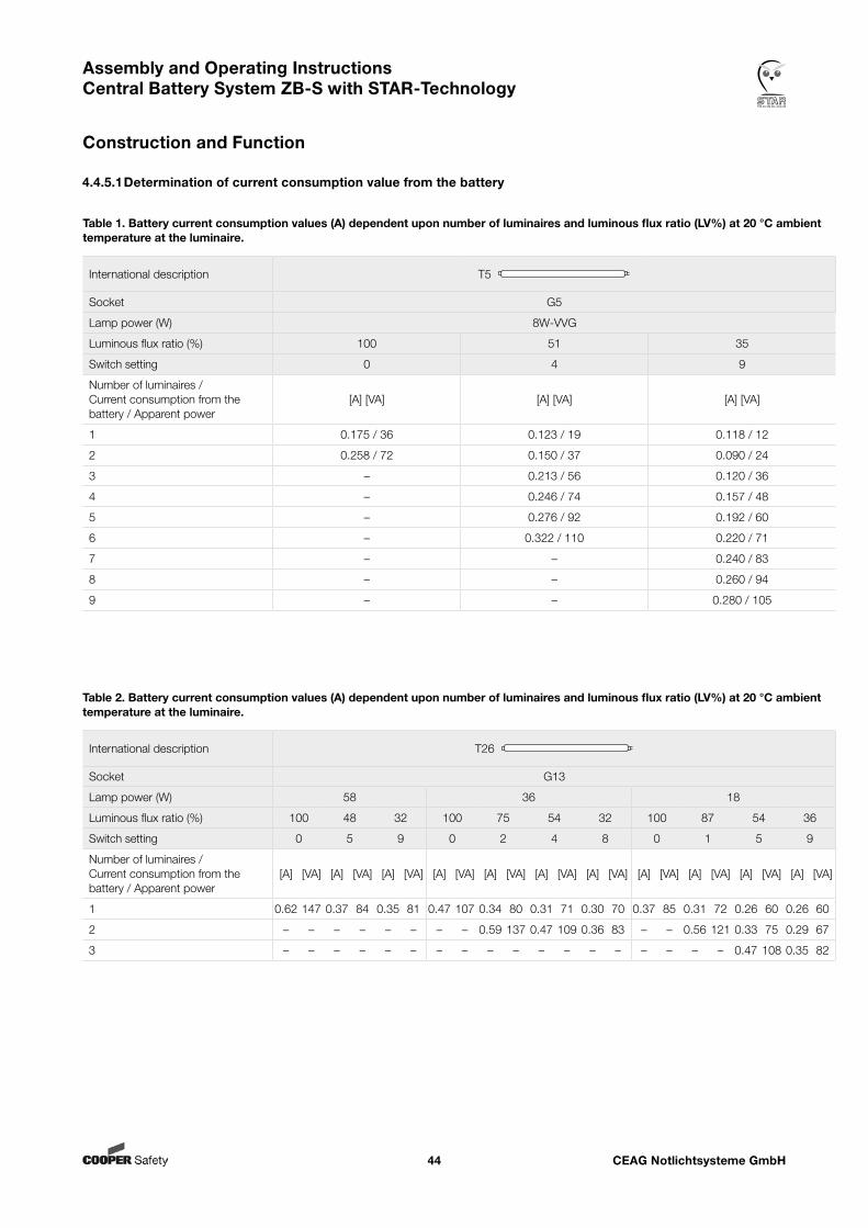
CEAG Notlichtsysteme GmbH44
Assembly and Operating Instructions Central Battery System ZB-S with STAR-Technology
Construction and Function
4.4.5.1 Determination of current consumption value from the battery
International description T5
Socket G5
Lamp power (W) 8W-VVG
Luminous flux ratio (%) 100 51 35
Switch setting 0 4 9
Number of luminaires / Current consumption from the battery / Apparent power
[A] [VA] [A] [VA] [A] [VA]
1 0.175 / 36 0.123 / 19 0.118 / 12
2 0.258 / 72 0.150 / 37 0.090 / 24
3 – 0.213 / 56 0.120 / 36
4 – 0.246 / 74 0.157 / 48
5 – 0.276 / 92 0.192 / 60
6 – 0.322 / 110 0.220 / 71
7 – – 0.240 / 83
8 – – 0.260 / 94
9 – – 0.280 / 105
Table 1. Battery current consumption values (A) dependent upon number of luminaires and luminous flux ratio (LV%) at 20 °C ambient temperature at the luminaire.
International description T26
Socket G13
Lamp power (W) 58 36 18
Luminous flux ratio (%) 100 48 32 100 75 54 32 100 87 54 36
Switch setting 0 5 9 0 2 4 8 0 1 5 9
Number of luminaires / Current consumption from the battery / Apparent power
[A] [VA] [A] [VA] [A] [VA] [A] [VA] [A] [VA] [A] [VA] [A] [VA] [A] [VA] [A] [VA] [A] [VA] [A] [VA]
1 0.62 147 0.37 84 0.35 81 0.47 107 0.34 80 0.31 71 0.30 70 0.37 85 0.31 72 0.26 60 0.26 60
2 – – – – – – – – 0.59 137 0.47 109 0.36 83 – – 0.56 121 0.33 75 0.29 67
3 – – – – – – – – – – – – – – – – – – 0.47 108 0.35 82
Table 2. Battery current consumption values (A) dependent upon number of luminaires and luminous flux ratio (LV%) at 20 °C ambient temperature at the luminaire.
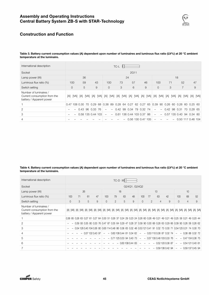
CEAG Notlichtsysteme GmbH45
Assembly and Operating Instructions Central Battery System ZB-S with STAR-Technology
Construction and Function
International description TC-L
Socket 2G11
Lamp power (W) 36 24 18
Luminous flux ratio (%) 100 59 43 100 73 57 46 100 71 52 47
Switch setting 0 5 9 0 3 6 9 0 3 7 9
Number of luminaires / Current consumption from the battery / Apparent power
[A] [VA] [A] [VA] [A] [VA] [A] [VA] [A] [VA] [A] [VA] [A] [VA] [A] [VA] [A] [VA] [A] [VA] [A] [VA]
1 0.47 108 0.30 70 0.29 68 0.38 89 0.28 64 0.27 62 0.27 65 0.39 90 0.26 60 0.26 60 0.25 60
2 – – 0.43 96 0.33 76 – – 0.42 99 0.34 79 0.32 74 – – 0.42 98 0.31 70 0.28 65
3 – – 0.58 135 0.44 103 – – 0.61 136 0.44 103 0.37 86 – – 0.57 135 0.40 94 0.34 80
4 – – – – – – – – – – 0.56 130 0.47 105 – – – – 0.50 117 0.46 104
Table 3. Battery current consumption values (A) dependent upon number of luminaires and luminous flux ratio (LV%) at 20 °C ambient temperature at the luminaire.
International description TC-D
Socket G24Q1. G24Q2
Lamp power (W) 26 18 13 10
Luminous flux ratio (%) 100 71 61 47 100 79 63 48 100 77 63 42 100 68 52
Switch setting 0 3 5 9 0 2 5 9 0 2 4 9 0 4 9
Number of luminaires / Current consumption from the battery / Apparent power
[A] [VA] [A] [VA] [A] [VA] [A] [VA] [A] [VA] [A] [VA] [A] [VA] [A] [VA] [A] [VA] [A] [VA] [A] [VA] [A] [VA] [A] [VA] [A] [VA] [A] [VA]
1 0.36 85 0.28 63 0.27 61 0.27 64 0.30 51 0.26 37 0.24 29 0.23 24 0.26 60 0.26 49 0.21 49 0.21 49 0.25 58 0.21 49 0.20 44
2 – – 0.39 93 0.35 80 0.33 76 0.47 87 0.35 64 0.29 47 0.28 37 0.39 90 0.30 68 0.28 63 0.29 66 0.39 90 0.26 58 0.26 62
3 – – 0.54 126 0.45 104 0.36 80 0.65 114 0.48 86 0.36 65 0.32 48 0.53 121 0.41 91 0.32 73 0.30 71 0.54 125 0.31 74 0.30 70
4 – – – – 0.57 132 0.43 97 – – 0.60 106 0.44 81 0.34 62 – – 0.53 110 0.38 87 0.32 74 – – 0.38 88 0.32 72
5 – – – – – – – – – – 0.71 125 0.53 94 0.40 73 – – 0.57 130 0.48 103 0.33 76 – – 0.47 104 0.36 75
6 – – – – – – – – – – – – 0.60 108 0.44 83 – – – – 0.52 120 0.38 87 – – 0.54 121 0.40 81
7 – – – – – – – – – – – – – – – – – – – – 0.59 136 0.42 94 – – 0.59 137 0.45 94
Table 4. Battery current consumption values (A) dependent upon number of luminaires and luminous flux ratio (LV%) at 20 °C ambient temperature at the luminaire.
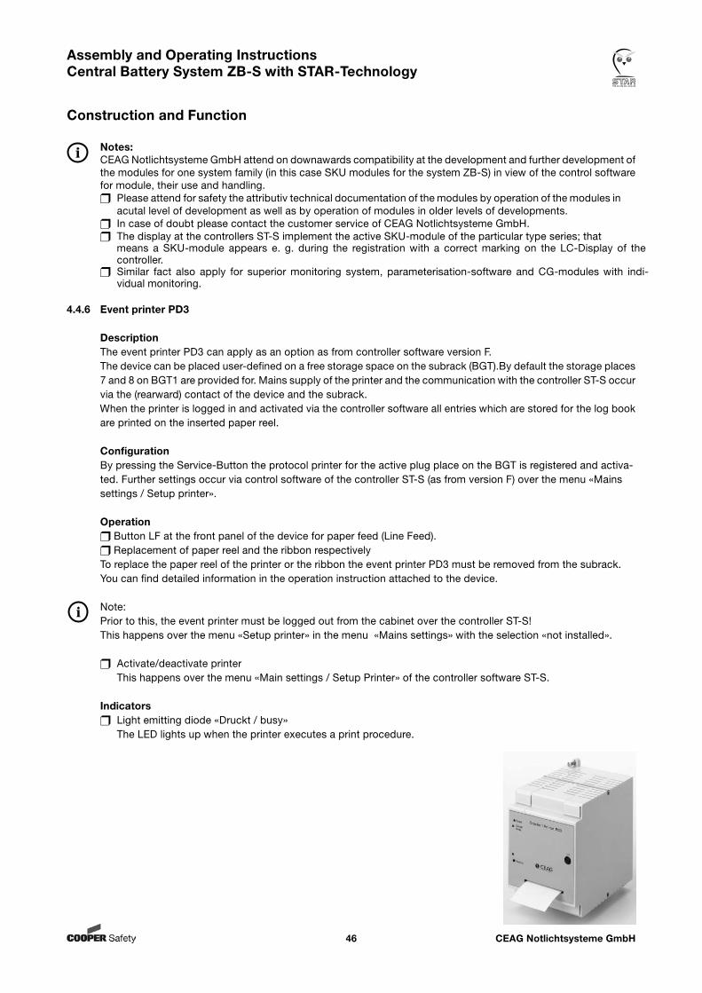
CEAG Notlichtsysteme GmbH46
Assembly and Operating Instructions Central Battery System ZB-S with STAR-Technology
Construction and Function
Notes:CEAG Notlichtsysteme GmbH attend on downawards compatibility at the development and further development of the modules for one system family (in this case SKU modules for the system ZB-S) in view of the control software for module, their use and handling. Please attend for safety the attributiv technical documentation of the modules by operation of the modules in acutal level of development as well as by operation of modules in older levels of developments. In case of doubt please contact the customer service of CEAG Notlichtsysteme GmbH. The display at the controllers ST-S implement the active SKU-module of the particular type series; that means a SKU-module appears e. g. during the registration with a correct marking on the LC-Display of the controller. Similar fact also apply for superior monitoring system, parameterisation-software and CG-modules with indi- vidual monitoring.
4.4.6 Event printer PD3
DescriptionThe event printer PD3 can apply as an option as from controller software version F.The device can be placed user-defined on a free storage space on the subrack (BGT).By default the storage places 7 and 8 on BGT1 are provided for. Mains supply of the printer and the communication with the controller ST-S occur via the (rearward) contact of the device and the subrack.When the printer is logged in and activated via the controller software all entries which are stored for the log book are printed on the inserted paper reel.
ConfigurationBy pressing the Service-Button the protocol printer for the active plug place on the BGT is registered and activa- ted. Further settings occur via control software of the controller ST-S (as from version F) over the menu «Mains settings / Setup printer».
Operation Button LF at the front panel of the device for paper feed (Line Feed). Replacement of paper reel and the ribbon respectivelyTo replace the paper reel of the printer or the ribbon the event printer PD3 must be removed from the subrack. You can find detailed information in the operation instruction attached to the device.
Note:Prior to this, the event printer must be logged out from the cabinet over the controller ST-S!This happens over the menu «Setup printer» in the menu «Mains settings» with the selection «not installed».
Activate/deactivate printer This happens over the menu «Main settings / Setup Printer» of the controller software ST-S.
Indicators Light emitting diode «Druckt / busy» The LED lights up when the printer executes a print procedure.
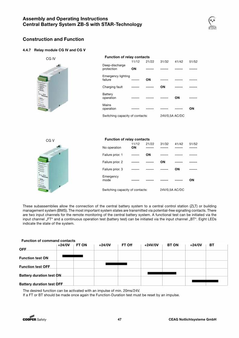
CEAG Notlichtsysteme GmbH47
Assembly and Operating Instructions Central Battery System ZB-S with STAR-Technology
Construction and Function
4.4.7 Relay module CG IV and CG V
The desired function can be activated with an impulse of min. 20ms/24V.If a FT or BT should be made once again the Function-Duration test must be reset by an impulse.
Function of command contacts +24/0V FT ON +24/0V FT Off +24V/0V BT ON +24/0V BT OFF
Function test ON
Function test OFF
Battery duration test ON
Battery duration test OFF
Function of relay contacts 11/12 21/22 31/32 41/42 51/52Deep-dischargeprotection ON ------ ------ ------ ------
Emergency lightingfailure ------ ON ------ ------ ------
Charging fault ------ ------ ON ------ ------
Battery operation ------ ------ ------ ON ------
Mains operation ------ ------ ------ ------ ON
Switching capacity of contacts: 24V/0,5A AC/DC
Function of relay contacts 11/12 21/22 31/32 41/42 51/52No operation ON ------ ------ ------ ------
Failure prior. 1 ------ ON ------ ------ ------
Failure prior. 2 ------ ------ ON ------ ------
Failure prior. 3 ------ ------ ------ ON ------
Emergency mode ------ ------ ------ ------ ON
CG IV
CG V
Switching capacity of contacts: 24V/0,5A AC/DC
These subassemblies allow the connection of the central battery system to a central control station (ZLT) or building management system (BMS). The most important system states are transmitted via potential-free signalling contacts. There are two input channels for the remote monitoring of the central battery system. A functional test can be initiated via the input channel „FT“ and a continuous operation test (battery test) can be initiated via the input channel „BT“. Eight LEDs indicate the state of the system.
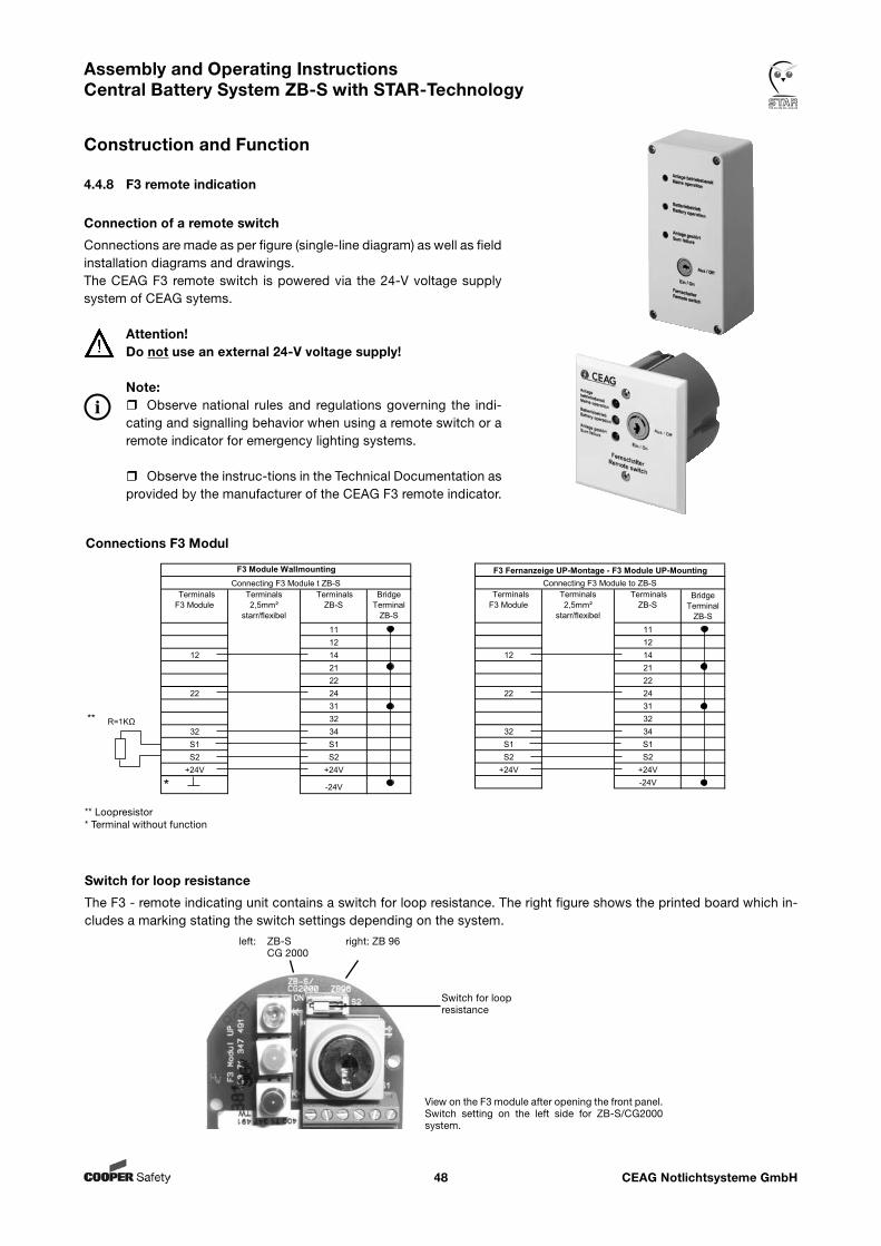
CEAG Notlichtsysteme GmbH48
Assembly and Operating Instructions Central Battery System ZB-S with STAR-Technology
Construction and Function
** Loopresistor* Terminal without function
Connections F3 Modul
Switch for loopresistance
Switch for loop resistance
The F3 - remote indicating unit contains a switch for loop resistance. The right figure shows the printed board which in-cludes a marking stating the switch settings depending on the system.
left: ZB-S right: ZB 96 CG 2000
View on the F3 module after opening the front panel.Switch setting on the left side for ZB-S/CG2000 system.
Klemmen F3 Fernanzeige
Klemmen2,5mm²
starr/flexibel
Klemmen ZB-S
Brücke Klemme
ZB-S
Terminals F3 Module
Terminals2,5mm²
starr/flexibel
Terminals ZB-S
Bridge Terminal
ZB-S
11 1112 12
12 14 12 1421 2122 22
22 24 22 2431 31
** 32 ** 3232 34 32 34S1 S1 S1 S1S2 S2 S2 S2
+24V +24V +24V +24V
* -24V * -24V
Klemmen F3 Fernanzeige
Klemmen2,5mm²
starr/flexibel
Klemmen ZB-S
Brücke Klemme
ZB-S
Terminals F3 Module
Terminals2,5mm²
starr/flexibel
Terminals ZB-S
Bridge Terminal
ZB-S11 1112 12
12 14 12 1421 2122 22
22 24 22 2431 3132 32
32 34 32 34S1 S1 S1 S1S2 S2 S2 S2
+24V +24V +24V +24V-24V -24V
F3 Fernanzeige Wandmontage F3 Module WallmountingConnecting F3 Module t ZB-S
F3 Fernanzeige UP-Montage F3 Fernanzeige UP-Montage - F3 Module UP-MountingConnecting F3 Module to ZB-S
Anschluss F 3 Fernanzeige an ZB-S
Anschluss F 3 Fernanzeige an ZB-S
R=1KΩ R=1KΩ
Klemmen F3 Fernanzeige
Klemmen2,5mm²
starr/flexibel
Klemmen ZB-S
Brücke Klemme
ZB-S
Terminals F3 Module
Terminals2,5mm²
starr/flexibel
Terminals ZB-S
Bridge Terminal
ZB-S
11 1112 12
12 14 12 1421 2122 22
22 24 22 2431 31
** 32 ** 3232 34 32 34S1 S1 S1 S1S2 S2 S2 S2
+24V +24V +24V +24V
* -24V * -24V
Klemmen F3 Fernanzeige
Klemmen2,5mm²
starr/flexibel
Klemmen ZB-S
Brücke Klemme
ZB-S
Terminals F3 Module
Terminals2,5mm²
starr/flexibel
Terminals ZB-S
Bridge Terminal
ZB-S11 1112 12
12 14 12 1421 2122 22
22 24 22 2431 3132 32
32 34 32 34S1 S1 S1 S1S2 S2 S2 S2
+24V +24V +24V +24V-24V -24V
F3 Fernanzeige Wandmontage F3 Module WallmountingConnecting F3 Module t ZB-S
F3 Fernanzeige UP-Montage F3 Fernanzeige UP-Montage - F3 Module UP-MountingConnecting F3 Module to ZB-S
Anschluss F 3 Fernanzeige an ZB-S
Anschluss F 3 Fernanzeige an ZB-S
R=1KΩ R=1KΩ
Connection of a remote switch
Connections are made as per figure (single-line diagram) as well as field installation diagrams and drawings. The CEAG F3 remote switch is powered via the 24-V voltage supply system of CEAG sytems.
Attention!Do not use an external 24-V voltage supply!
Note:Observe national rules and regulations governing the indi-cating and signalling behavior when using a remote switch or a remote indicator for emergency lighting systems.
Observe the instruc-tions in the Technical Documentation as provided by the manufacturer of the CEAG F3 remote indicator.
4.4.8 F3 remote indication
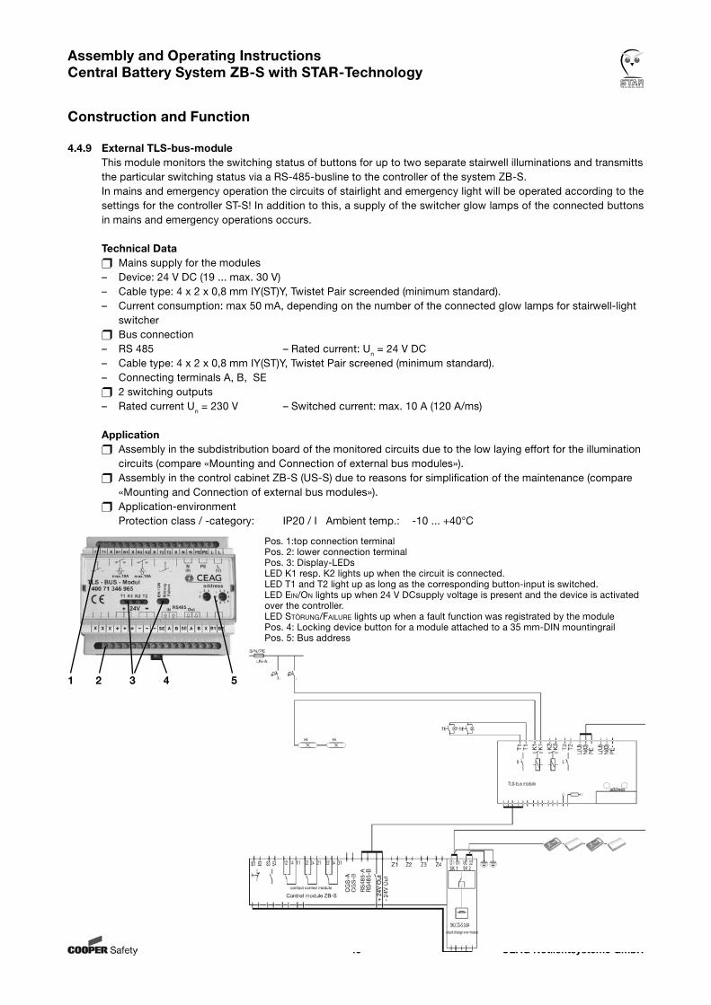
CEAG Notlichtsysteme GmbH49
Assembly and Operating Instructions Central Battery System ZB-S with STAR-Technology
Construction and Function
4.4.9 External TLS-bus-moduleThis module monitors the switching status of buttons for up to two separate stairwell illuminations and transmitts the particular switching status via a RS-485-busline to the controller of the system ZB-S.In mains and emergency operation the circuits of stairlight and emergency light will be operated according to the settings for the controller ST-S! In addition to this, a supply of the switcher glow lamps of the connected buttons in mains and emergency operations occurs.
Technical Data Mains supply for the modules– Device: 24 V DC (19 ... max. 30 V)– Cable type: 4 x 2 x 0,8 mm IY(ST)Y, Twistet Pair screended (minimum standard).– Current consumption: max 50 mA, depending on the number of the connected glow lamps for stairwell-light switcher Bus connection– RS 485 – Rated current: Un = 24 V DC– Cable type: 4 x 2 x 0,8 mm IY(ST)Y, Twistet Pair screened (minimum standard).– Connecting terminals A, B, SE 2 switching outputs– Rated current Un = 230 V – Switched current: max. 10 A (120 A/ms)
Application Assembly in the subdistribution board of the monitored circuits due to the low laying effort for the illumination circuits (compare «Mounting and Connection of external bus modules»). Assembly in the control cabinet ZB-S (US-S) due to reasons for simplification of the maintenance (compare «Mounting and Connection of external bus modules»). Application-environment Protection class / -category: IP20 / I Ambient temp.: -10 ... +40°C
1 2 3 4 5
Pos. 1:top connection terminalPos. 2: lower connection terminalPos. 3: Display-LEDs LED K1 resp. K2 lights up when the circuit is connected.LED T1 and T2 light up as long as the corresponding button-input is switched.LED ein/on lights up when 24 V DCsupply voltage is present and the device is activated over the controller.LED sTörung/Failure lights up when a fault function was registrated by the modulePos. 4: Locking device button for a module attached to a 35 mm-DIN mountingrail Pos. 5: Bus address
CEAG Notlichtsysteme GmbH50
Assembly and Operating Instructions Central Battery System ZB-S with STAR-Technology
Construction and Function
4.4.10 External DLS/3Ph-bus-module and ext. DLS/3Ph-bus-module inverseThis electronic monitoring module acts as a (light-)switch scan and/or for monitoring of the phases of a mains power supply (e. g. in a subdistribution board):Luminaires of the general lighting and the safety lighting are switched in mains operation in accordance with the switch position and the settings for the controller ST-S.In emergency operation (e. g. after a message about a breakdown of monitored phases of the mains power supply) the circuits of the safety lighting will be operated according to the settings of the controller ST-S.DLS/3Ph-bus-modules are available in two performances which only differ in view of the switching perfor- mance (inverting of the DLS circuits)!
Technical Data Mains supply for the modules – Device: 24 V DC (19 ... max. 30 V)– Cable type: 4 x 2 x 0.8 mm IY(ST)Y, Twistet Pair screened (minimal standard).– Current consumption: 20 mA (15 ... 25 mA) with 8 connected circuits Bus connection– RS 485– Rated voltage Un = 24 V DC– Cable type: 4 x 2 x 0.8 mm IY(ST)Y, Twistet Pair screened (minimum requirements).– Connection terminal A, B, SE Input circuits– up to 8 potential-free disconnected– Rated voltage Un = 230 V Switching performance of DLS-circuits DLS/3Ph/ Switching performance of DLS circuits DLS/3Ph inverse U < 138 V = OFF U < 138 V = ON U > 195 V = ON U > 195 V = OFF Switching performance of 3Ph circuits (same for DLS/3Ph module and DLS/3Ph module inverse) U < 138 V = OFF U > 195 V = ON Application:Two operation modes are available: (pure) DLS-mode (mixed) DLS/3Ph-mode With a dispatcher (pos. 5) the operation mode can be chosen. Assembly in the subdistribution board of the monitored circuits due to the low laying effort for the illumination circuits (compare «Mounting and connection of external bus modules»). Assembly in the control cabinet ZB-S (US-S) due to reasons for simplification of the maintenance (compare «Mounting and connection of external modules»). Application-environment Protection class / -category: IP20 / I Ambient temp.: -10 ... +40°C
Notes: Please observe the regulations for bus-technology and screening on the following pages. For planning and application of the modules we advice to observe the technical documentations attached to the modules and the catalogues ofCEAG Notlichtsysteme GmbH! Optically, the inverse and the non-inverse DLS/3Ph-module only differ in the printed description and the item number! Due to break or short-circuit of the RS485-bus line all connected luminaires will be switched on!
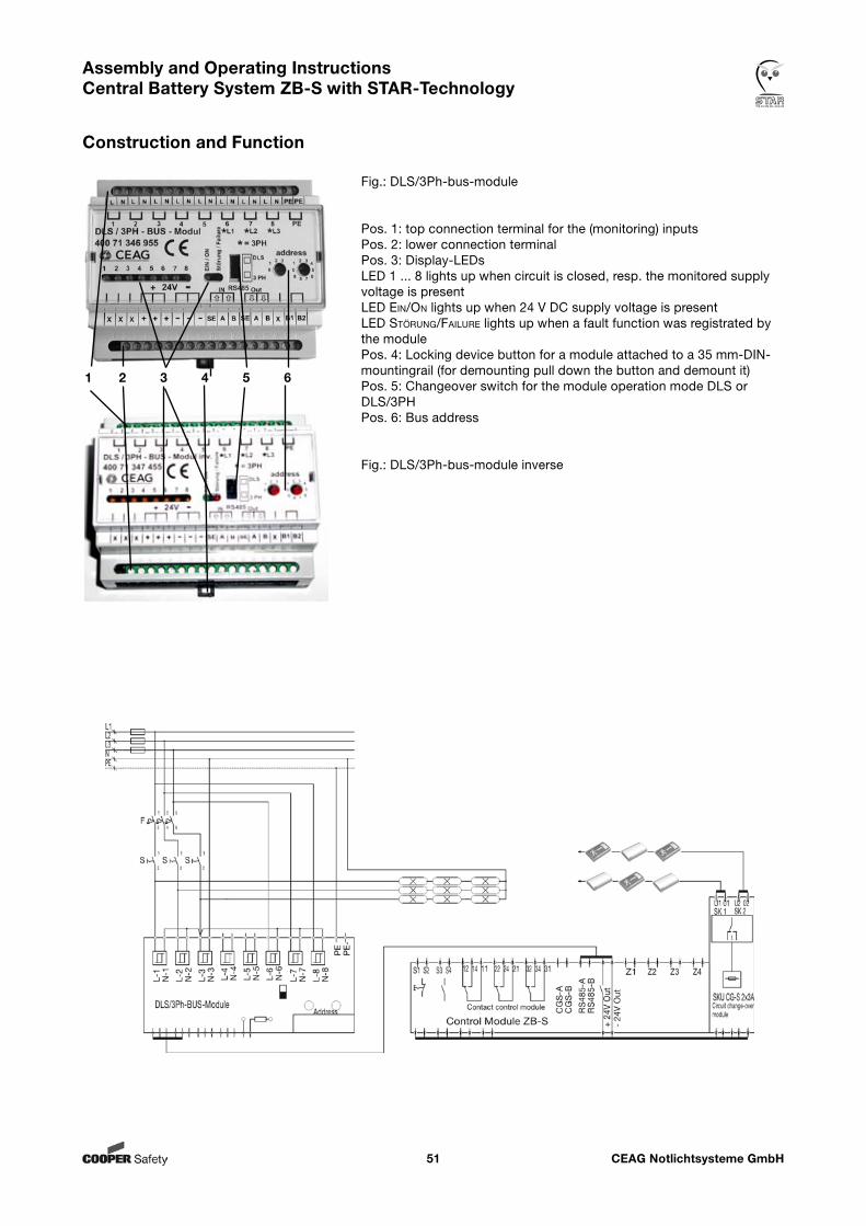
CEAG Notlichtsysteme GmbH51
Assembly and Operating Instructions Central Battery System ZB-S with STAR-Technology
Construction and Function
1 2 3 4 5 6
Fig.: DLS/3Ph-bus-module
Pos. 1: top connection terminal for the (monitoring) inputsPos. 2: lower connection terminalPos. 3: Display-LEDs LED 1 ... 8 lights up when circuit is closed, resp. the monitored supply voltage is presentLED ein/on lights up when 24 V DC supply voltage is presentLED sTörung/Failure lights up when a fault function was registrated by the modulePos. 4: Locking device button for a module attached to a 35 mm-DIN-mountingrail (for demounting pull down the button and demount it)Pos. 5: Changeover switch for the module operation mode DLS or DLS/3PH Pos. 6: Bus address
Fig.: DLS/3Ph-bus-module inverse
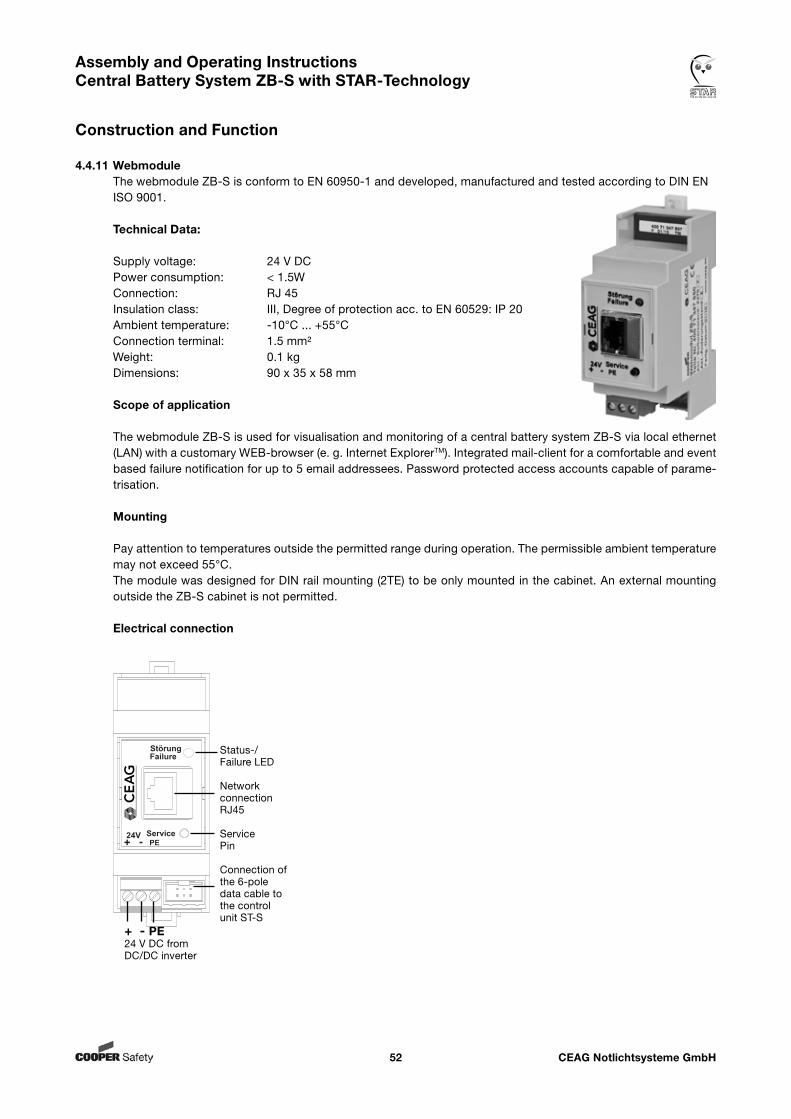
CEAG Notlichtsysteme GmbH52
Assembly and Operating Instructions Central Battery System ZB-S with STAR-Technology
Construction and Function
4.4.11 WebmoduleThe webmodule ZB-S is conform to EN 60950-1 and developed, manufactured and tested according to DIN EN ISO 9001.
Technical Data:
Supply voltage: 24 V DCPower consumption: < 1.5WConnection: RJ 45Insulation class: III, Degree of protection acc. to EN 60529: IP 20Ambient temperature: -10°C ... +55°CConnection terminal: 1.5 mm²Weight: 0.1 kgDimensions: 90 x 35 x 58 mm
Scope of application
The webmodule ZB-S is used for visualisation and monitoring of a central battery system ZB-S via local ethernet (LAN) with a customary WEB-browser (e. g. Internet ExplorerTM). Integrated mail-client for a comfortable and event based failure notification for up to 5 email addressees. Password protected access accounts capable of parame-trisation.
Mounting
Pay attention to temperatures outside the permitted range during operation. The permissible ambient temperature may not exceed 55°C.The module was designed for DIN rail mounting (2TE) to be only mounted in the cabinet. An external mounting outside the ZB-S cabinet is not permitted.
Electrical connection
Status-/Failure LED
NetworkconnectionRJ45
ServicePin
Connection of the 6-poledata cable to the controlunit ST-S
Service
StörungFailure
24V+ - PE
+ - PE24 V DC fromDC/DC inverter
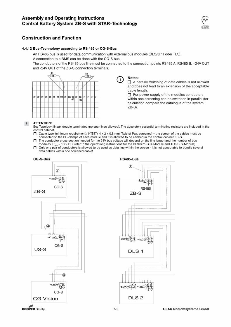
CEAG Notlichtsysteme GmbH53
Assembly and Operating Instructions Central Battery System ZB-S with STAR-Technology
Construction and Function
4.4.12 Bus-Technology according to RS 485 or CG-S-Bus
An RS485 bus is used for data communication with external bus modules (DLS/3PH oder TLS).A connection to a BMS can be done with the CG-S bus.The conductors of the RS485 bus line must be connected to the connection points RS485 A, RS485 B, +24V OUT and -24V OUT of the ZB-S connection terminals.
ATTENTION!Bus Topology: linear, double terminated (no spur lines allowed). The absolutely essential terminating resistors are included in the control cabinet. Cable type (minimum requirement): IY(ST)Y 4 x 2 x 0.8 mm (Twistet Pair, screened) – the screen of the cables must be connected to the SE-clamps of each module and it is allowed to be earthed in the control cabinet ZB-S. The conductor cross-section needed for the 24V bus voltage will depend on the line length and the number of bus modules (Umin = 19 V DC, refer to the operationg instructions for the DLS/3Ph-Bus-Module and TLS-Bus-Module) Only one pair of conductors is allowed to be used as data line within the screen - it is not acceptable to bundle several data cables within one screened cable!
CG-S-Bus RS485-Bus
Notes: A parallel switching of data cables is not allowed and does not lead to an extension of the acceptable cable length. For power supply of the modules conductors within one screening can be switched in parallel (for calculation compare the catalogue of the system ZB-S).
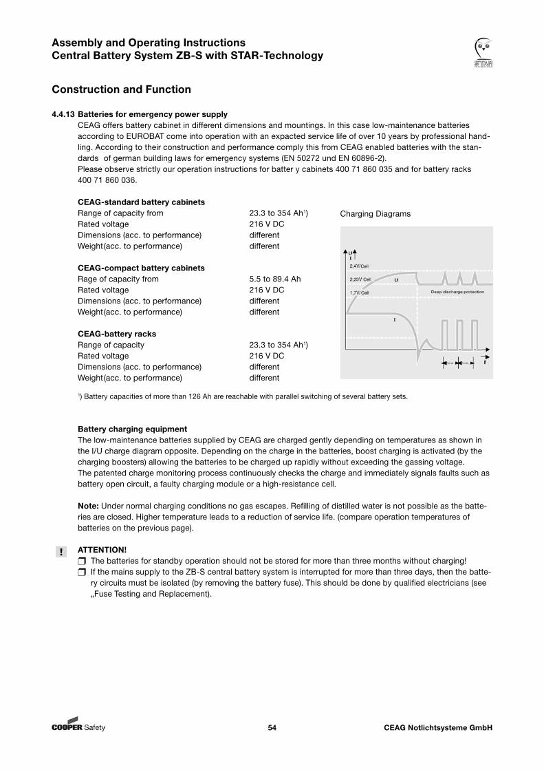
CEAG Notlichtsysteme GmbH54
Assembly and Operating Instructions Central Battery System ZB-S with STAR-Technology
Construction and Function
4.4.13 Batteries for emergency power supply CEAG offers battery cabinet in different dimensions and mountings. In this case low-maintenance batteries according to EUROBAT come into operation with an expacted service life of over 10 years by professional hand- ling. According to their construction and performance comply this from CEAG enabled batteries with the stan- dards of german building laws for emergency systems (EN 50272 und EN 60896-2). Please observe strictly our operation instructions for batter y cabinets 400 71 860 035 and for battery racks 400 71 860 036.
CEAG-standard battery cabinets Range of capacity from 23.3 to 354 Ah1) Rated voltage 216 V DC Dimensions (acc. to performance) different
Weight (acc. to performance) different
CEAG-compact battery cabinets Rage of capacity from 5.5 to 89.4 Ah Rated voltage 216 V DC Dimensions (acc. to performance) different
Weight (acc. to performance) different
CEAG-battery racks Range of capacity 23.3 to 354 Ah1) Rated voltage 216 V DC Dimensions (acc. to performance) different
Weight (acc. to performance) different
1) Battery capacities of more than 126 Ah are reachable with parallel switching of several battery sets.
Battery charging equipment The low-maintenance batteries supplied by CEAG are charged gently depending on temperatures as shown in the I/U charge diagram opposite. Depending on the charge in the batteries, boost charging is activated (by the charging boosters) allowing the batteries to be charged up rapidly without exceeding the gassing voltage. The patented charge monitoring process continuously checks the charge and immediately signals faults such as battery open circuit, a faulty charging module or a high-resistance cell.
Note: Under normal charging conditions no gas escapes. Refilling of distilled water is not possible as the batte- ries are closed. Higher temperature leads to a reduction of service life. (compare operation temperatures of batteries on the previous page).
ATTENTION! The batteries for standby operation should not be stored for more than three months without charging! If the mains supply to the ZB-S central battery system is interrupted for more than three days, then the batte- ry circuits must be isolated (by removing the battery fuse). This should be done by qualified electricians (see „Fuse Testing and Replacement).
Charging Diagrams
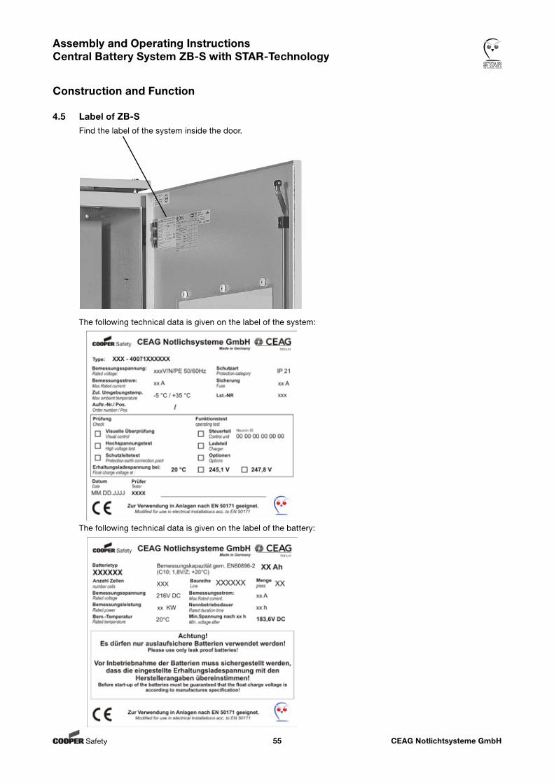
CEAG Notlichtsysteme GmbH55
Assembly and Operating Instructions Central Battery System ZB-S with STAR-Technology
Construction and Function
4.5 Label of ZB-SFind the label of the system inside the door.
The following technical data is given on the label of the system:
The following technical data is given on the label of the battery:
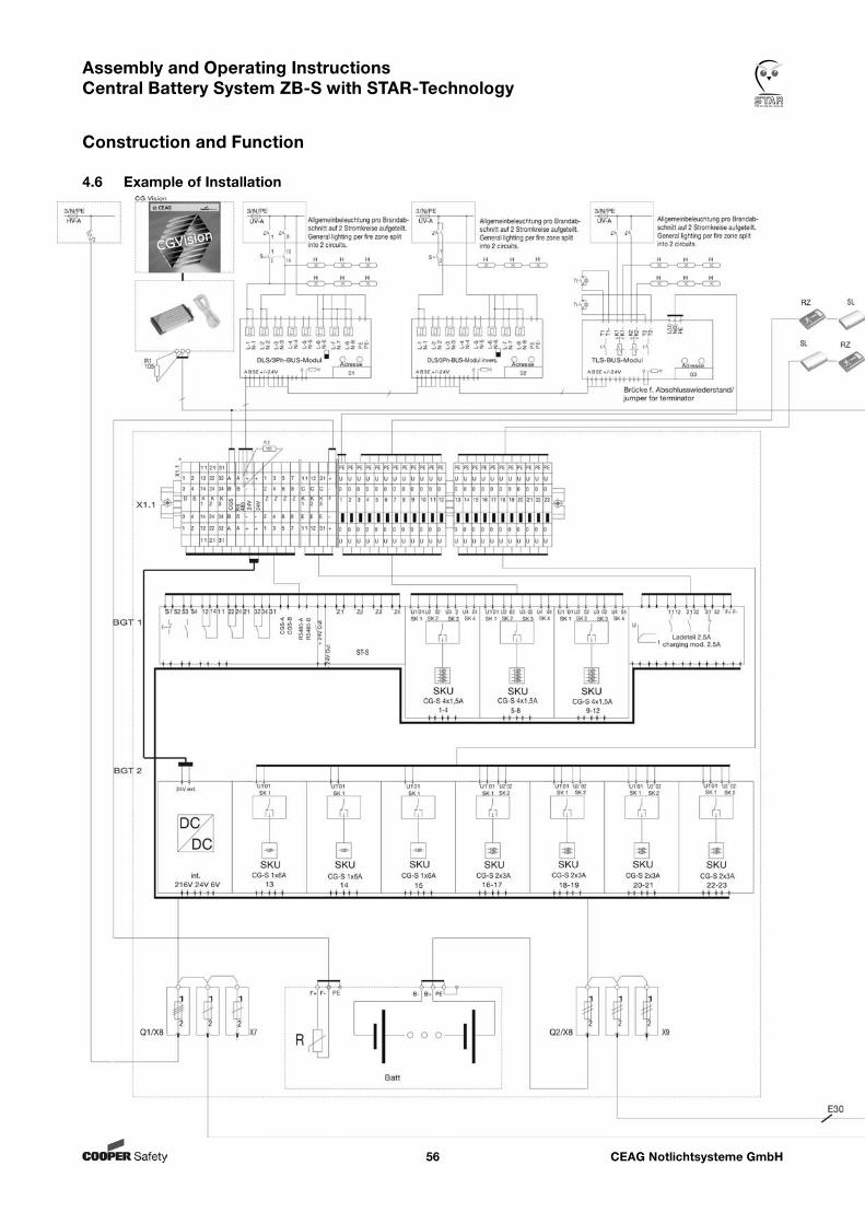
CEAG Notlichtsysteme GmbH56
Assembly and Operating Instructions Central Battery System ZB-S with STAR-Technology
Construction and Function
4.6 Example of Installation
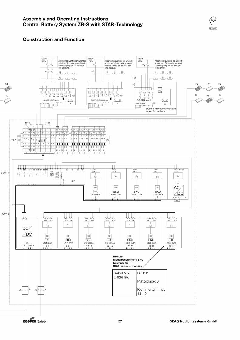
CEAG Notlichtsysteme GmbH57
Assembly and Operating Instructions Central Battery System ZB-S with STAR-Technology
Construction and Function
CEAG Notlichtsysteme GmbH58
Assembly and Operating Instructions Central Battery System ZB-S with STAR-Technology
5. Transport, Packaging and Storage
5.1 Safety Notes WARNING! Risk of Injury!There is a risk of injury when transporting or loading due to falling parts.
ATTENTION! Damage to Property!Batteries will be destroyed or damaged by improper transport.
The following safety notes have to be observed: Never lift loads over person´s head. Always move battery with great care and attention. Only use lifting accessories and hoisting devices with enough loading capacity. Always handle and store the ZB-S system upright (see markings and „do not tilt“ sign on the pack) Avoid ingress of dust and moisture during handling. Ensure that all transport routes - are clear (sufficient width and headroom for all transport movements), - provide enough room for persons to take evasive action if loads tip over or slip, - have sufficient loadbearing capacity (for the load, transport packaging and handling equipment) - could not overstrain the used transport equipment in regard of increase and constitution of underground. Use only - handling equipment (e. g. pallet trucks, fork trucks, etc.) - slinging equipment (lifting beams, chains, ropes, etc.) - and securing equipment (chocks, timbers, guide/tensioning/securing ropes, etc.) that are in technically perfect condition and of adequate loadbearing capacity. Follow all information shown on the transport packaging and/or on the device/control cabinet relating to handling, transport position, slinging points. The equipment must be handled by persons familiar with the appropriate procedures and signals and able to carry out the handling operations properly and with due regard to safety and hazard procedures.
Batteries
For battery handling and storage please follow the battery manufacturer´s directions and the instructions about the battery cabinets..
5.2 Transport inspectionCheck delivery on receipt for completeness and for transport damages, immediately. If external damage is detected do not accept the delivery, except under protest.
5.3 PackagingIf no return - agreement exists for packing material separate it according to type and size for further use.
ATTENTION!Packing material has to be recycled in an environmentally friendly way and according to the local provisions governing disposal. If necessary, commission special recycling company.
Observe notes for handling printed on the packing material!
Transport, Packaging and Storage
CEAG Notlichtsysteme GmbH59
Assembly and Operating Instructions Central Battery System ZB-S with STAR-Technology
5.4 StorageKeep packages closed up to mounting and observe the external marked arrangement and storage notes.Store packages under the following conditions: Not to be stored outside Keep dry and dust-free The storage location should be clean and tidy The time of storage should be as short as possible (FIFO - method) It is forbidden to stack one pallet/system above the other
Attend for batteries: When storing batteries as spare parts the information in the ‚Battery cabinets‘ / ‚Battery rack‘ installation and operating instructions must be observed. If the mains supply to the ZB-S central battery system is interrupted for more than three days, then the batte- ry circuits must be isolated (by removing the battery fuse). This should be done by qualified electricians.
NOTES!Please oberserve additionally the operation instructions for battery cabinets and/or battery racks.
Transport, Packaging and Storage
CEAG Notlichtsysteme GmbH60
Assembly and Operating Instructions Central Battery System ZB-S with STAR-Technology
Installation
6. Installation
6.1 Safety Notes
WARNING! Risk of Injury!Improper mounting and installation can cause serious personal injury and/or material damage. This work must only be performed by authorised, skilled and adequate personnel who have received instructions providing information on the device and in observance of the local safety regulations.
Ensure there is enough free moving space. Ensure orderliness and cleanliness at the working place. Loose tools lying around are dangerous! Assure a sufficient cooling of the system! Observe the environmental conditions regarding the insulation class and degree of protection (acc. to the protection against a contact of conducting parts and ingress of dust, impurity or moisture) Ensure that the cable length in an emergency light circuit to the last luminaire in the circuit does not exceed the maximum permitted cable length. Special regulations for ESF-E30: Enclosures must be fitted to the masonry horizontally. The masonry must be designed for a circuit integrity of at least 30 minutes. The circuit integrity of the masonry must not be impaired by assembly.
The modular layout of the items of equipment illustrated in these assembly and operating instructions may differ from that supplied. Particular features of custom designs are described in the project documents that must be ordered separately.
WARNING! Work on the general supply network and the running of load, signal and control cables and connection of the battery power supply must be carried out by qualified electricians with special knowledge of the legal and technical basics for the assembly and operation of emergency lighting systems. This takes also place for initi- al commissioning or re-commissioning. Take all necessary measures to ensure occupational health and safety! As well as compliance with general trade standards and procdures, this specifically includes complying with chapters 1+2 of these instructions.
NOTES! All connecting cables must be laid according to the relevant electrical engineering codes of practice and standards (e. g. standard series DIN VDE 100). You must also comply with all standards and directives of the country in which the system is installed and operated. Secure all the cable entry and exit openings in the control cabinet with the supplied M-type glands or rubber grommets to prevent damage to the cables and ingress of moisture. Attention! Using RCD´s in the mains lead to protect against indirect contact acc. to VDE 100 part 410, please observe the following: Fault activations can be caused by different actions: • Activation caused by installation failures. • Activation caused by external actions. • Activation caused by capacitive leakages. When designing and executing, it is important to use the right RCD. Please attend to the following when using RCDs in the network supplies of systems:
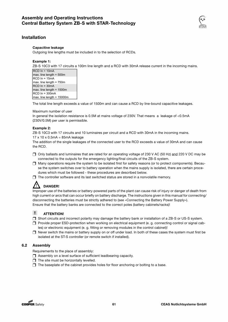
CEAG Notlichtsysteme GmbH61
Assembly and Operating Instructions Central Battery System ZB-S with STAR-Technology
Installation
Capacitive leakageOutgoing line lengths must be included in to the selection of RCDs.
Example 1:ZB-S 10C3 with 17 circuits a 100m line length and a RCD with 30mA release current in the incoming mains.
The total line length exceeds a value of 1500m and can cause a RCD by line-bound capacitive leakages. Maximum number of user In general the isolation resistance is 0.5M at mains voltage of 230V. That means a leakage of <0.5mA (230V/0.5M) per user is permissible.
Example 2: ZB-S 10C3 with 17 circuits and 10 luminaires per circuit and a RCD with 30mA in the incoming mains. 17 x 10 x 0.5mA = 85mA leakage The addition of the single leakages of the connected user to the RCD exceeds a value of 30mA and can cause the RCD.
Only ballasts and luminaires that are rated for an operating voltage of 230 V AC (50 Hz) and 220 V DC may be connected to the outputs for the emergency lighting/final circuits of the ZB-S system. Many operations require the system to be isolated first for safety reasons (or to protect components). Becau- se the system switches over to battery operation when the mains supply is isolated, there are certain proce- dures which must be followed - these procedures are described below. The controller software and its last switched status are stored in a nonvolatile memory.
DANGER!Improper use of the batteries or battery-powered parts of the plant can cause risk of injury or danger of death from high current or arcs that can occur briefly on battery discharge. The instructions given in this manual for connecting/disconnecting the batteries must be strictly adhered to (see «Connecting the Battery Power Supply»).Ensure that the battery banks are connected to the correct poles (battery cabinets/racks)!
ATTENTION! Short circuits and incorrect polarity may damage the battery bank or installation of a ZB-S or US-S system. Provide proper ESD-protection when working on electrical equipment (e. g. connecting control or signal cab- les) or electronic equipment (e. g. fitting or removing modules in the control cabinet)! Never switch the mains or battery supply on or off under load. In both of these cases the system must first be isolated at the ST-S controller (or remote switch if installed).
6.2 AssemblyRequirements to the place of assembly: Assembly on a level surface of sufficient leadbearing capacity. The site must be horizontally levelled. The baseplate of the cabinet provides holes for floor anchoring or bolting to a base.
RCD In = 10mAmax. line length = 500mRCD In = 15mAmax. line length = 750mRCD In = 30mAmax. line length = 1500mRCD In = 300mAmax. line length = 15000m
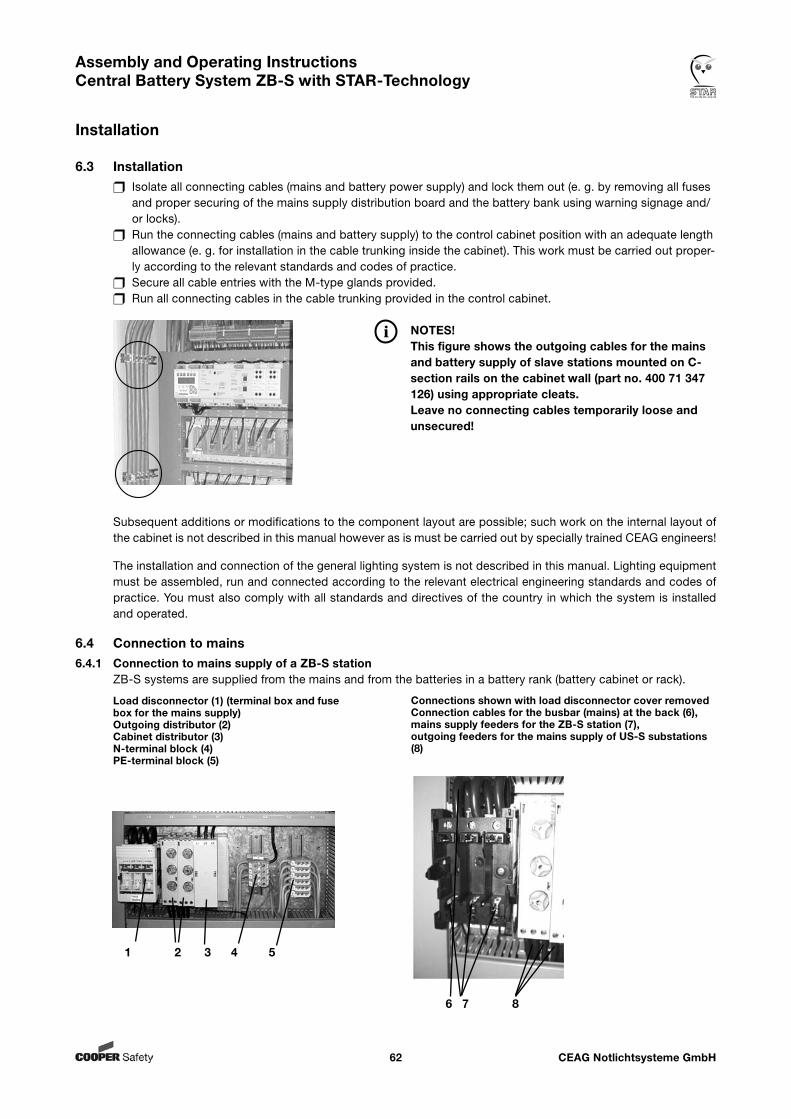
CEAG Notlichtsysteme GmbH62
Assembly and Operating Instructions Central Battery System ZB-S with STAR-Technology
Installation
6.3 Installation Isolate all connecting cables (mains and battery power supply) and lock them out (e. g. by removing all fuses and proper securing of the mains supply distribution board and the battery bank using warning signage and/ or locks). Run the connecting cables (mains and battery supply) to the control cabinet position with an adequate length allowance (e. g. for installation in the cable trunking inside the cabinet). This work must be carried out proper- ly according to the relevant standards and codes of practice. Secure all cable entries with the M-type glands provided. Run all connecting cables in the cable trunking provided in the control cabinet.
NOTES! This figure shows the outgoing cables for the mains and battery supply of slave stations mounted on C- section rails on the cabinet wall (part no. 400 71 347 126) using appropriate cleats. Leave no connecting cables temporarily loose and unsecured!
Subsequent additions or modifications to the component layout are possible; such work on the internal layout of the cabinet is not described in this manual however as is must be carried out by specially trained CEAG engineers!
The installation and connection of the general lighting system is not described in this manual. Lighting equipment must be assembled, run and connected according to the relevant electrical engineering standards and codes of practice. You must also comply with all standards and directives of the country in which the system is installed and operated.
6.4 Connection to mains6.4.1 Connection to mains supply of a ZB-S station
ZB-S systems are supplied from the mains and from the batteries in a battery rank (battery cabinet or rack).
Load disconnector (1) (terminal box and fuse box for the mains supply) Outgoing distributor (2)Cabinet distributor (3)N-terminal block (4) PE-terminal block (5)
Connections shown with load disconnector cover removed Connection cables for the busbar (mains) at the back (6),mains supply feeders for the ZB-S station (7),outgoing feeders for the mains supply of US-S substations (8)
1 2 3 4 5
6 7 8
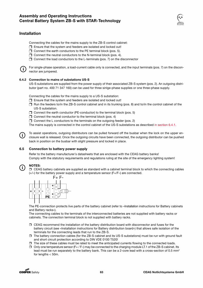
CEAG Notlichtsysteme GmbH63
Assembly and Operating Instructions Central Battery System ZB-S with STAR-Technology
Installation
Connecting the cables for the mains supply to the ZB-S control cabinet: Ensure that the system and feeders are isolated and locked out! Connect the earth conductors to the PE terminal block (pos. 5). Connect the neutral conductors to the N-terminal block (pos. 4). Connect the load conductors to the L-terminals (pos. 7) on the disconnector For single-phase operation, a load-current cable only is connected, and the input terminals (pos. 7) on the discon-nector are jumpered.
6.4.2 Connection to mains of substations US-SUS-S substations are supplied from the power supply of their associated ZB-S system (pos. 2). An outgoing distri-butor (part no. 400 71 347 160) can be used for three sinlge-phase supplies or one three-phase supply.
Connecting the cables for the mains supply to a US-S substation: Ensure that the system and feeders are isolated and locked out! Run the feeders to/in the ZB-S control cabinet and in its trunking (pos. 8) and to/in the control cabinet of the US-S substation. Connect the earth conductor (PE-conductor) to the terminal block (pos. 5) Connect the neutral conductor to the terminal block (pos. 4) Connect the L conductors to the terminals on the outgoing feeder (pos. 2)The mains supply is connected in the control cabinet of the US-S substations as described in section 6.4.1.
To assist operations, outgoing distributors can be pulled forward off the busbar when the lock on the upper en-closure wall is released. Once the outgoing circuits have been connected, the outgoing distributor can be pushed back in position on the busbar with slight pressure and locked in place.
6.5 Connection to battery power supplyRefer to the battery manufacturer´s datasheets that are enclosed with the CEAG battery banks!Comply with the statutory requirements and regulations ruling at the site of the emergency lighting system!
NOTES: CEAG battery cabinets are supplied as standard with a cabinet terminal block to which the connecting cables (+/–) for the battery power supply and a temperature sensor (F+/F–) are connected.
The PE-connection protects live parts of the battery cabinet (refer to «Installation instructions for Battery cabinets and Battery racks»).The connecting cables to the terminals of the interconnected batteries are not supplied with battery racks or cabinets. The connection terminal block is not supplied with battery racks.
CEAG recommend the installation of the battery distribution board with disconnector and fuses for the battery circuit (see «Installation instructions for Battery distribution board») that allows safe isolation of the terminals for the connecting leads that run to the ZB-S. The battery connection cables (for the ZB-S cabinet and its US-S substations) must be run with ground fault and short circuit protection according to DIN VDE 0100 T520! The size of these cables must be rated to meet the anticipated currents flowing to the connected loads. Only one temperature sensor (F+ / F–) may be connected to the charging module LT.1 of the ZB-S cabinet. Its lead must be run separately to the battery bank. This can be a 2-core lead with a cross-section of 0.5 mm2 for lengths < 50m.
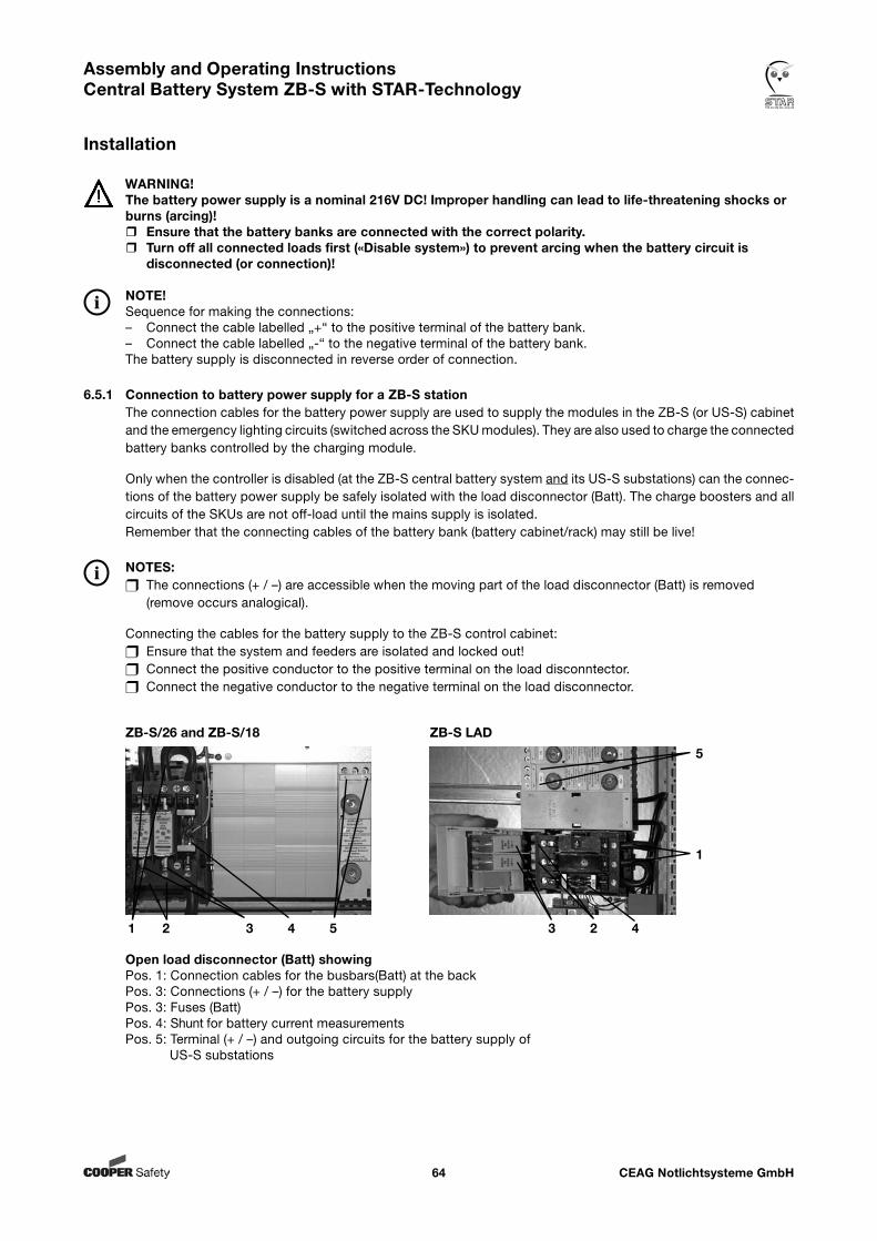
CEAG Notlichtsysteme GmbH64
Assembly and Operating Instructions Central Battery System ZB-S with STAR-Technology
Installation
Open load disconnector (Batt) showingPos. 1: Connection cables for the busbars(Batt) at the back Pos. 3: Connections (+ / –) for the battery supplyPos. 3: Fuses (Batt)Pos. 4: Shunt for battery current measurementsPos. 5: Terminal (+ / –) and outgoing circuits for the battery supply of US-S substations
WARNING!The battery power supply is a nominal 216V DC! Improper handling can lead to life-threatening shocks or burns (arcing)! Ensure that the battery banks are connected with the correct polarity. Turn off all connected loads first («Disable system») to prevent arcing when the battery circuit is
disconnected (or connection)!
NOTE!Sequence for making the connections:– Connect the cable labelled „+“ to the positive terminal of the battery bank. – Connect the cable labelled „-“ to the negative terminal of the battery bank.The battery supply is disconnected in reverse order of connection.
6.5.1 Connection to battery power supply for a ZB-S stationThe connection cables for the battery power supply are used to supply the modules in the ZB-S (or US-S) cabinet and the emergency lighting circuits (switched across the SKU modules). They are also used to charge the connected battery banks controlled by the charging module.
Only when the controller is disabled (at the ZB-S central battery system and its US-S substations) can the connec-tions of the battery power supply be safely isolated with the load disconnector (Batt). The charge boosters and all circuits of the SKUs are not off-load until the mains supply is isolated.Remember that the connecting cables of the battery bank (battery cabinet/rack) may still be live!
NOTES: The connections (+ / –) are accessible when the moving part of the load disconnector (Batt) is removed (remove occurs analogical).
Connecting the cables for the battery supply to the ZB-S control cabinet: Ensure that the system and feeders are isolated and locked out! Connect the positive conductor to the positive terminal on the load disconntector. Connect the negative conductor to the negative terminal on the load disconnector.
1 2 3 4 5 3 2 4
1
5
ZB-S/26 and ZB-S/18 ZB-S LAD
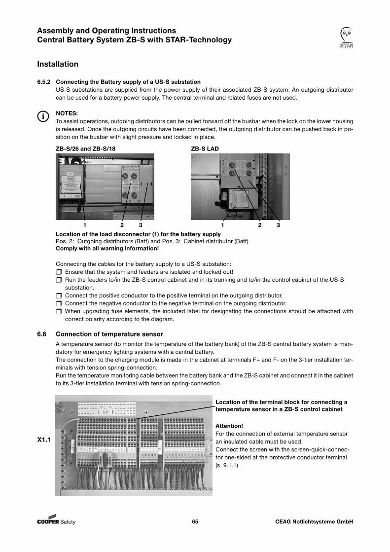
CEAG Notlichtsysteme GmbH65
Assembly and Operating Instructions Central Battery System ZB-S with STAR-Technology
Installation
6.5.2 Connecting the Battery supply of a US-S substationUS-S substations are supplied from the power supply of their associated ZB-S system. An outgoing distributor can be used for a battery power supply. The central terminal and related fuses are not used.
NOTES:To assist operations, outgoing distributors can be pulled forward off the busbar when the lock on the lower housing is released. Once the outgoing circuits have been connected, the outgoing distributor can be pushed back in po-sition on the busbar with slight pressure and locked in place.
Location of the load disconnector (1) for the battery supply Pos. 2: Outgoing distributors (Batt) and Pos. 3: Cabinet distributor (Batt)Comply with all warning information!
Connecting the cables for the battery supply to a US-S substation: Ensure that the system and feeders are isolated and locked out! Run the feeders to/in the ZB-S control cabinet and in its trunking and to/in the control cabinet of the US-S substation. Connect the positive conductor to the positive terminal on the outgoing distributor. Connect the negative conductor to the negative terminal on the outgoing distributor. When upgrading fuse elements, the included label for designating the connections should be attached with correct polarity according to the diagram.
6.6 Connection of temperature sensorA temperature sensor (to monitor the temperature of the battery bank) of the ZB-S central battery system is man-datory for emergency lighting systems with a central battery.The connection to the charging module is made in the cabinet at terminals F+ and F- on the 3-tier installation ter-minals with tension spring-connection.Run the temperature monitoring cable between the battery bank and the ZB-S cabinet and connect it in the cabinet to its 3-tier installation terminal with tension spring-connection.
Location of the terminal block for connecting a temperature sensor in a ZB-S control cabinet
X1.1
Attention!For the connection of external temperature sensor an insulated cable must be used.Connect the screen with the screen-quick-connec-tor one-sided at the protective conductor terminal (s. 9.1.1).
ZB-S/26 and ZB-S/18 ZB-S LAD
1 2 3 1 2 3
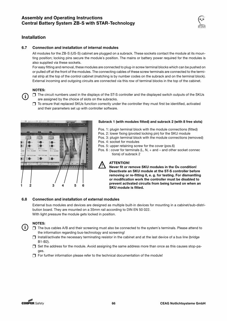
CEAG Notlichtsysteme GmbH66
Assembly and Operating Instructions Central Battery System ZB-S with STAR-Technology
Installation
6.8 Connection and installation of external modulesExternal bus modules and devices are designed as multiple built-in devices for mounting in a cabinet/sub-distri-bution board. They are mounted on a 35mm rail according to DIN EN 50 022. With light pressure the module gets locked in position.
NOTES: The bus cables A/B and their screening must also be connected to the system´s terminals. Please attend to the information regarding bus-technology and screening! Install/activate the necessary terminating resistor in the cabinet and at the last device of a bus line (bridge B1-B2). Set the address for the module. Avoid assigning the same address more than once as this causes stop-pa- ges. For further information please refer to the technical documentation of the module!
6.7 Connection and installation of internal modulesAll modules for the ZB-S (US-S) cabinet are plugged on a subrack. These sockets contact the module at its moun-ting position; locking pins secure the module´s position. The mains or battery power required for the modules is also supplied via these sockets.For easy fitting and removal, these modules are connected to plug-in screw terminal blocks which can be pushed on or pulled off at the front of the modules. The connecting cables of these screw terminals are connected to the termi-nal strip at the top of the control cabinet (matching is by number codes on the subrack and on the terminal block).External incoming and outgoing circuits are connected via this row of terminal blocks in the top of the cabinet.
NOTES: The circuit numbers used in the displays of the ST-S controller and the displayed switch outputs of the SKUs are assigned by the choice of slots on the subracks. To ensure that replaced SKUs function correctly under the controller they must first be identified, activated and their parameters set up with controller software.
Pos. 1: plugin terminal block with the module connections (fitted)Pos. 2: lower fixing (pivoted locking pin) for the SKU modulePos. 3: plugin terminal block with the module connections (removed)Pos. 4: socket for modulesPos. 5: upper retaining screw for the cover (pos.6)Pos. 6 : cover for terminals (L, N, + and – and other socket connec tions) of subrack 2
ATTENTION!Never fit or remove SKU modules in the On condition! Deactivate an SKU module at the ST-S controller before removing or re-fitting it, e. g. for testing. For dismantling or modification work the controller must be disabled to prevent activated circuits from being turned on when an SKU module is fitted.
Subrack 1 (with modules fitted) and subrack 2 (with 8 free slots)
1 2 3 4 5 6
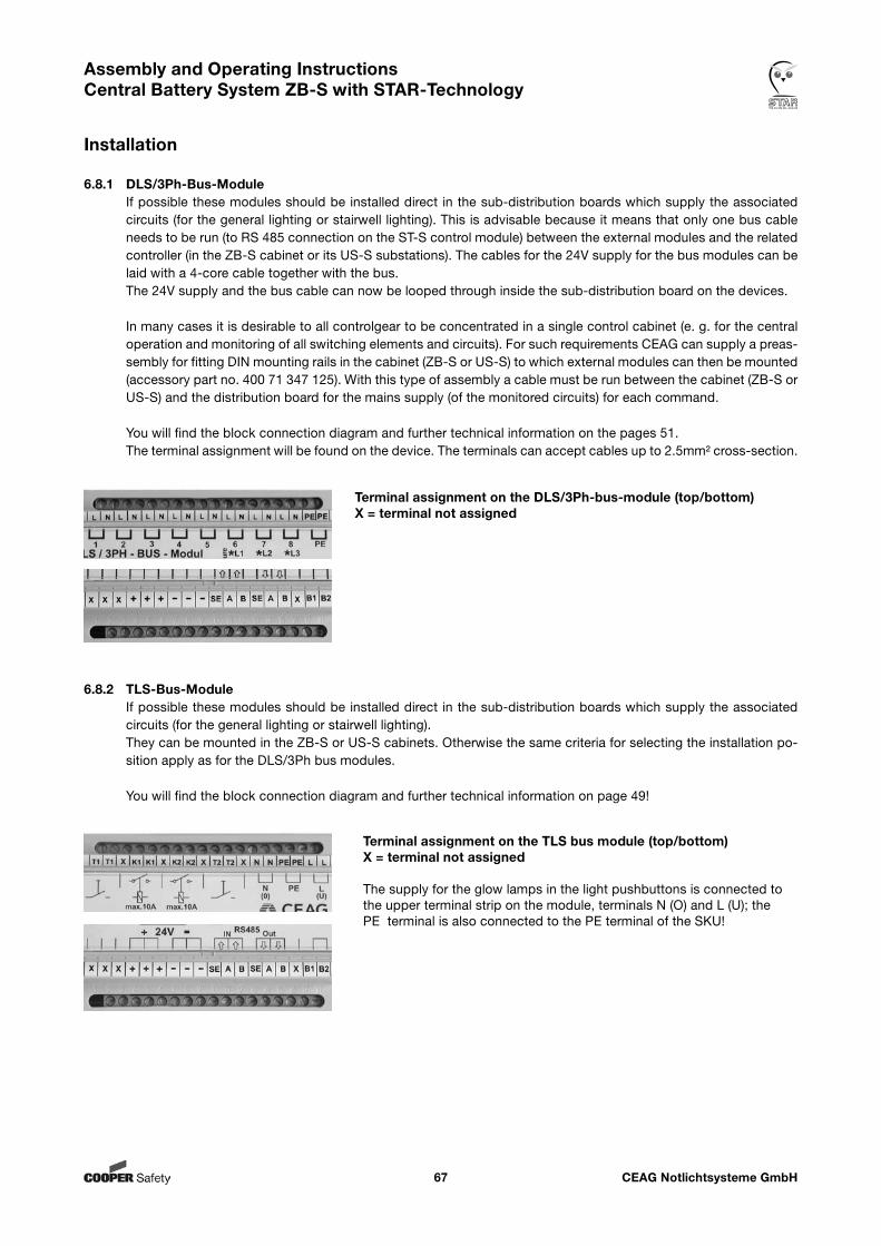
CEAG Notlichtsysteme GmbH67
Assembly and Operating Instructions Central Battery System ZB-S with STAR-Technology
Installation
6.8.1 DLS/3Ph-Bus-ModuleIf possible these modules should be installed direct in the sub-distribution boards which supply the associated circuits (for the general lighting or stairwell lighting). This is advisable because it means that only one bus cable needs to be run (to RS 485 connection on the ST-S control module) between the external modules and the related controller (in the ZB-S cabinet or its US-S substations). The cables for the 24V supply for the bus modules can be laid with a 4-core cable together with the bus.The 24V supply and the bus cable can now be looped through inside the sub-distribution board on the devices.
In many cases it is desirable to all controlgear to be concentrated in a single control cabinet (e. g. for the central operation and monitoring of all switching elements and circuits). For such requirements CEAG can supply a preas-sembly for fitting DIN mounting rails in the cabinet (ZB-S or US-S) to which external modules can then be mounted (accessory part no. 400 71 347 125). With this type of assembly a cable must be run between the cabinet (ZB-S or US-S) and the distribution board for the mains supply (of the monitored circuits) for each command.
You will find the block connection diagram and further technical information on the pages 51.The terminal assignment will be found on the device. The terminals can accept cables up to 2.5mm² cross-section.
Terminal assignment on the DLS/3Ph-bus-module (top/bottom) X = terminal not assigned
6.8.2 TLS-Bus-ModuleIf possible these modules should be installed direct in the sub-distribution boards which supply the associated circuits (for the general lighting or stairwell lighting).They can be mounted in the ZB-S or US-S cabinets. Otherwise the same criteria for selecting the installation po-sition apply as for the DLS/3Ph bus modules.
You will find the block connection diagram and further technical information on page 49!
Terminal assignment on the TLS bus module (top/bottom) X = terminal not assigned
The supply for the glow lamps in the light pushbuttons is connected to the upper terminal strip on the module, terminals N (O) and L (U); the PE terminal is also connected to the PE terminal of the SKU!
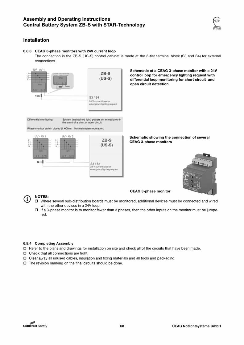
CEAG Notlichtsysteme GmbH68
Assembly and Operating Instructions Central Battery System ZB-S with STAR-Technology
Installation
6.8.4 Completing Assembly Refer to the plans and drawings for installation on site and check all of the circuits that have been made. Check that all connections are tight. Clear away all unused cables, insulation and fixing materials and all tools and packaging. The revision marking on the final circuits should be done.
6.8.3 CEAG 3-phase monitors with 24V current loopThe connection in the ZB-S (US-S) control cabinet is made at the 3-tier terminal block (S3 and S4) for external connections.
Schematic of a CEAG 3-phase monitor with a 24V control loop for emergency lighting request with differential loop monitoring for short circuit and open circuit detection
Schematic showing the connection of several CEAG 3-phase monitors
NOTES: Where several sub-distribution boards must be monitored, additional devices must be connected and wired with the other devices in a 24V loop. If a 3-phase monitor is to monitor fewer than 3 phases, then the other inputs on the monitor must be jumpe- red.
CEAG 3-phase monitor
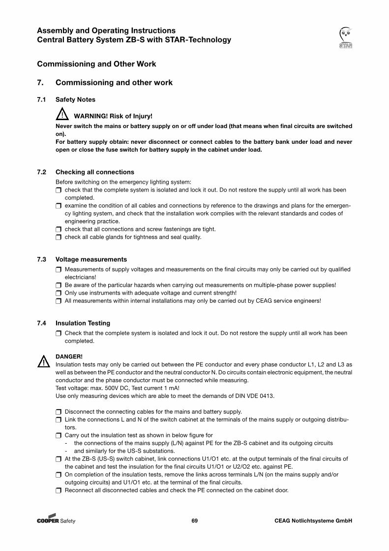
CEAG Notlichtsysteme GmbH69
Assembly and Operating Instructions Central Battery System ZB-S with STAR-Technology
Commissioning and Other Work
7. Commissioning and other work
7.1 Safety Notes
WARNING! Risk of Injury!Never switch the mains or battery supply on or off under load (that means when final circuits are switched on). For battery supply obtain: never disconnect or connect cables to the battery bank under load and never open or close the fuse switch for battery supply in the cabinet under load.
7.2 Checking all connectionsBefore switching on the emergency lighting system: check that the complete system is isolated and lock it out. Do not restore the supply until all work has been completed. examine the condition of all cables and connections by reference to the drawings and plans for the emergen- cy lighting system, and check that the installation work complies with the relevant standards and codes of engineering practice. check that all connections and screw fastenings are tight. check all cable glands for tightness and seal quality.
7.3 Voltage measurements Measurements of supply voltages and measurements on the final circuits may only be carried out by qualified electricians! Be aware of the particular hazards when carrying out measurements on multiple-phase power supplies! Only use instruments with adequate voltage and current strength! All measurements within internal installations may only be carried out by CEAG service engineers!
7.4 Insulation Testing Check that the complete system is isolated and lock it out. Do not restore the supply until all work has been completed.
DANGER!Insulation tests may only be carried out between the PE conductor and every phase conductor L1, L2 and L3 as well as between the PE conductor and the neutral conductor N. Do circuits contain electronic equipment, the neutral conductor and the phase conductor must be connected while measuring.Test voltage: max. 500V DC, Test current 1 mA!Use only measuring devices which are able to meet the demands of DIN VDE 0413.
Disconnect the connecting cables for the mains and battery supply. Link the connections L and N of the switch cabinet at the terminals of the mains supply or outgoing distribu- tors. Carry out the insulation test as shown in below figure for - the connections of the mains supply (L/N) against PE for the ZB-S cabinet and its outgoing circuits - and similarly for the US-S substations. At the ZB-S (US-S) switch cabinet, link connections U1/O1 etc. at the output terminals of the final circuits of the cabinet and test the insulation for the final circuits U1/O1 or U2/O2 etc. against PE. On completion of the insulation tests, remove the links across terminals L/N (on the mains supply and/or outgoing circuits) and U1/O1 etc. at the terminal of the final circuits. Reconnect all disconnected cables and check the PE connected on the cabinet door.
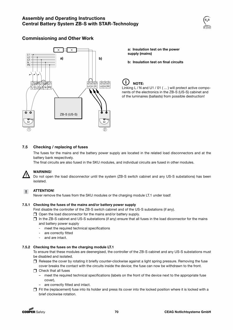
CEAG Notlichtsysteme GmbH70
Assembly and Operating Instructions Central Battery System ZB-S with STAR-Technology
Commissioning and Other Work
7.5 Checking / replacing of fusesThe fuses for the mains and the battery power supply are located in the related load disconnectors and at the battery bank respectively.The final circuits are also fused in the SKU modules, and individual circuits are fused in other modules.
WARNING!Do not open the load disconnector until the system (ZB-S switch cabinet and any US-S substations) has been isolated.
ATTENTION!Never remove the fuses from the SKU modules or the charging module LT.1 under load!
7.5.1 Checking the fuses of the mains and/or battery power supplyFirst disable the controller of the ZB-S switch cabinet and of the US-S substations (if any). Open the load disconnector for the mains and/or battery supply. In the ZB-S cabinet and US-S substations (if any) ensure that all fuses in the load diconnector for the mains and battery power supply - meet the required technical specifications - are correctly fitted - and are intact.
7.5.2 Checking the fuses on the charging module LT.1To ensure that these modules are deenergised, the controller of the ZB-S cabinet and any US-S substations must be disabled and isolated. Release the cover by rotating it briefly counter-clockwise against a light spring pressure. Removing the fuse cover breaks the contact with the circuits inside the device; the fuse can now be withdrawn to the front. Check that all fuses – meet the required technical specifications (labels on the front of the device next to the appropriate fuse cover), – are correctly fitted and intact. Fit the (replacement) fuse into its holder and press its cover into the locked position where it is locked with a brief clockwise rotation.
NOTE:Linking L / N and U1 / 01 ( ... ) will protect active compo-nents of the electronics in the ZB-S (US-S) cabinet and of the luminaires (ballasts) from possible destruction!
a: Insulation test on the powersupply (mains)
b: Insulation test on final circuits
ZB-S (US-S)
a) b)
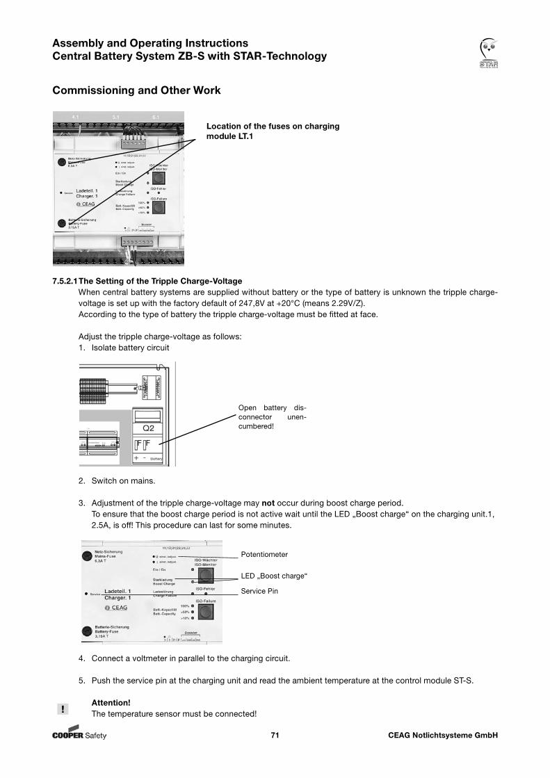
CEAG Notlichtsysteme GmbH71
Assembly and Operating Instructions Central Battery System ZB-S with STAR-Technology
Commissioning and Other Work
7.5.2.1 The Setting of the Tripple Charge-VoltageWhen central battery systems are supplied without battery or the type of battery is unknown the tripple charge-voltage is set up with the factory default of 247,8V at +20°C (means 2.29V/Z).According to the type of battery the tripple charge-voltage must be fitted at face.
Adjust the tripple charge-voltage as follows:1. Isolate battery circuit
2. Switch on mains.
3. Adjustment of the tripple charge-voltage may not occur during boost charge period. To ensure that the boost charge period is not active wait until the LED „Boost charge“ on the charging unit.1, 2.5A, is off! This procedure can last for some minutes.
4. Connect a voltmeter in parallel to the charging circuit.
5. Push the service pin at the charging unit and read the ambient temperature at the control module ST-S.
Attention! The temperature sensor must be connected!
Location of the fuses on charging module LT.1
Open battery dis-connector unen-cumbered!
LED „Boost charge“
Service Pin
Potentiometer
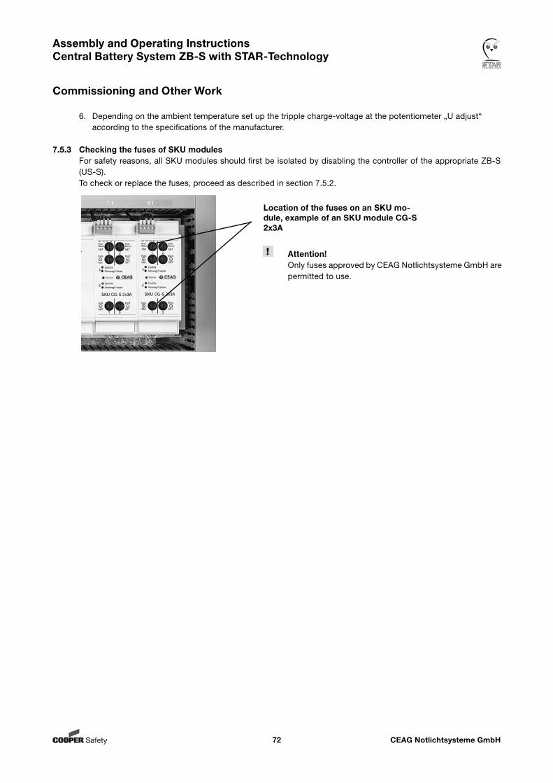
CEAG Notlichtsysteme GmbH72
Assembly and Operating Instructions Central Battery System ZB-S with STAR-Technology
Commissioning and Other Work
6. Depending on the ambient temperature set up the tripple charge-voltage at the potentiometer „U adjust“ according to the specifications of the manufacturer.
7.5.3 Checking the fuses of SKU modulesFor safety reasons, all SKU modules should first be isolated by disabling the controller of the appropriate ZB-S (US-S).To check or replace the fuses, proceed as described in section 7.5.2.
Location of the fuses on an SKU mo-dule, example of an SKU module CG-S 2x3A
Attention!Only fuses approved by CEAG Notlichtsysteme GmbH are permitted to use.
CEAG Notlichtsysteme GmbH73
Assembly and Operating Instructions Central Battery System ZB-S with STAR-Technology
Commissioning and Other Work
7.6 Checking and replacing internal modulesBefore checking or replacing the internal modules the emergency lighting system must be disconnected. Therefore observe: Block the system before isolating the emergency lighting system at the distribution board and/or battery sup- ply. This is done with the <<Block/release device>> option in menu 2 <<Block, reset>> in the controller soft- ware. Now isolate the battery power supply first and then isolate the mains supply. Lock out the isolations while work on the system is in progress or while the system is in an unsafe condition. NOTE!If a battery bank supplies a number of systems then all systems must be isolated first! Start by isolating at the lower levels of the US-S substations before you isolate the ZB-S central battery system.
Before you reconnect the supply at the terminals of the battery bank for the battery supply, power on the mains supply and ensure that the system is disabled. Only now should you power on the battery supply at the battery bank.
For mounting or dismounting of modules please see chapter 6.7 „Connection and installation of internal modules“ and all warning notices!
NOTE!On the SKU-modules you will find a Service push button that can be used for initial commissioning and for testing purposes. When it is pressed, the controller software displays addresses and characteristics of the selected module directly on the LC display of the controller.
7.7 Checking and replacing external modulesFor mounting and dismounting of a module please see chapter 6.8 „Connection and installation of external mo-dules“. Please observce the following: Set the address for the module. Avoid assigning the same address more than once as this causes stoppages. To ensure that replaced external modules function correctly under the controller they must first be identified, activated and their parameters set up with the controller software.
On the SKU-modules you will find a Service push button that can be used for initial commissioning and for testing purposes. When it is pressed, the controller software displays addresses and characteristics of the selected module directly on the LC display of the controller.
7.8 Powering up the systemThe following sequence of operations assumes that the system (ZB-S plus US-S substations) has first been isolated and locked out. If is also assumed that the parameter setup of the controller software or its switch settings have not been changed in the meantime! Switch on the mains supply to the ZB-S switch cabinet and its US-S substations at the load disconnector. Ensure that the controller of the ZB-S cabinet and any subsystems (US-S) are blocked. Secure this plant condition against unauthorised action! Switch on the battery supply to the ZB-S switch cabinet and its US-S substations at the load disconnector. Switch on the controllers with <<Release device>> menu option.
CEAG Notlichtsysteme GmbH74
Assembly and Operating Instructions Central Battery System ZB-S with STAR-Technology
Operating
8. Operating
8.1 Safety Notes
WARNING! Risk of Injury!Improper mounting and installation can cause serious personal injury and/or material damage. This work must only be performed by authorised, skilled and adequate personnel who have received instructions providing information on the device and in observance of the local safety regulations.
Before work begins: check its completeness and technical correctness, ensure there is enough free moving space.
During operation: When failures arise first of all switch system off and protect against reengagement.
When working on and with the device it is necessary to wear: Close fitting protective clothes (low tensile strength, no wide arms, no rings and further jewelry, etc.) Safety boots which protect against falling parts and against slipping on non-anti-slip floor.
8.2 General information about operatingA ZB-S or US-S system is operated at several different levels. First, a distinction must be made between: operating and monitoring the system during operation (test mode or normal operation). and setting up the system with the requirements (parameter settings for the ST-S controller) for the emer- gency lighting circuits and the user-assignable functions and function keys of the control module.
Operating and monitoring the system during operation can be done with the buttons and displays/LED indicators on the modules in the switch cabinet (ST-S, DC/DC converter, char- ging module, installed SKUs), remote indicators or CG controller F3 module or with a building services management system (BMS).
Setting up the system (and changing its parameter settings) can be done directly on the control module in the ZB-S (or US-S) switch cabinet or with a memory card using a standard PC running under a CEAG configuration software for the ZB-S sy- stem.
NOTE!The following descriptions are not covered by this manual as this requires detailed instructions within the technical documentation for these systems: Operating and monitoring the system with an F3 module, CG controller or building management system (BMS) Software-aided system setup using a memory card
Operating and monitoring the system, in the scope specified above, during operation (test mode or normal ope-ration) requires a knowledge of the operation of the ST-S control module in the switch cabinet, the key functions and displays/LEDs on the other modules in the switch cabinet of a ZB-S or US-S system, and the use of certain hardware components (checking and replacing fuses or checking and replacing modules). Otherwise please refer to the technical documentation for these components.
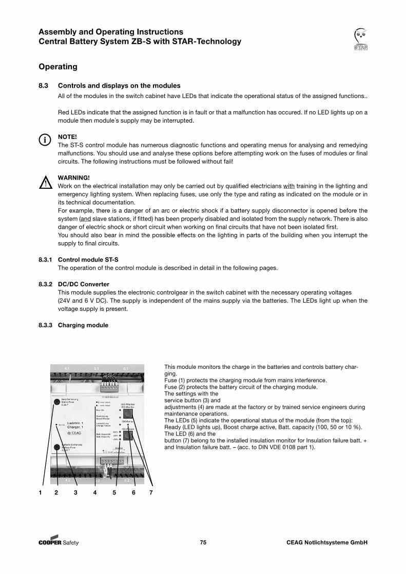
CEAG Notlichtsysteme GmbH75
Assembly and Operating Instructions Central Battery System ZB-S with STAR-Technology
Operating
8.3 Controls and displays on the modulesAll of the modules in the switch cabinet have LEDs that indicate the operational status of the assigned functions..
Red LEDs indicate that the assigned function is in fault or that a malfunction has occured. If no LED lights up on a module then module´s supply may be interrupted.
NOTE!The ST-S control module has numerous diagnostic functions and operating menus for analysing and remedying malfunctions. You should use and analyse these options before attempting work on the fuses of modules or final circuits. The following instructions must be followed without fail!
WARNING!Work on the electrical installation may only be carried out by qualified electricians with training in the lighting and emergency lighting system. When replacing fuses, use only the type and rating as indicated on the module or in its technical documentation. For example, there is a danger of an arc or electric shock if a battery supply disconnector is opened before the system (and slave stations, if fitted) has been properly disabled and isolated from the supply network. There is also danger of electric shock or short circuit when working on final circuits that have not been isolated first. You should also bear in mind the possible effects on the lighting in parts of the building when you interrupt the supply to final circuits.
8.3.1 Control module ST-SThe operation of the control module is described in detail in the following pages.
8.3.2 DC/DC ConverterThis module supplies the electronic controlgear in the switch cabinet with the necessary operating voltages (24V and 6 V DC). The supply is independent of the mains supply via the batteries. The LEDs light up when the voltage supply is present.
8.3.3 Charging module
1 2 3 4 5 6 7
This module monitors the charge in the batteries and controls battery char-ging. Fuse (1) protects the charging module from mains interference.Fuse (2) protects the battery circuit of the charging module. The settings with the service button (3) and adjustments (4) are made at the factory or by trained service engineers during maintenance operations. The LEDs (5) indicate the operational status of the module (from the top): Ready (LED lights up), Boost charge active, Batt. capacity (100, 50 or 10 %).The LED (6) and the button (7) belong to the installed insulation monitor for Insulation failure batt. + and Insulation failure batt. – (acc. to DIN VDE 0108 part 1).
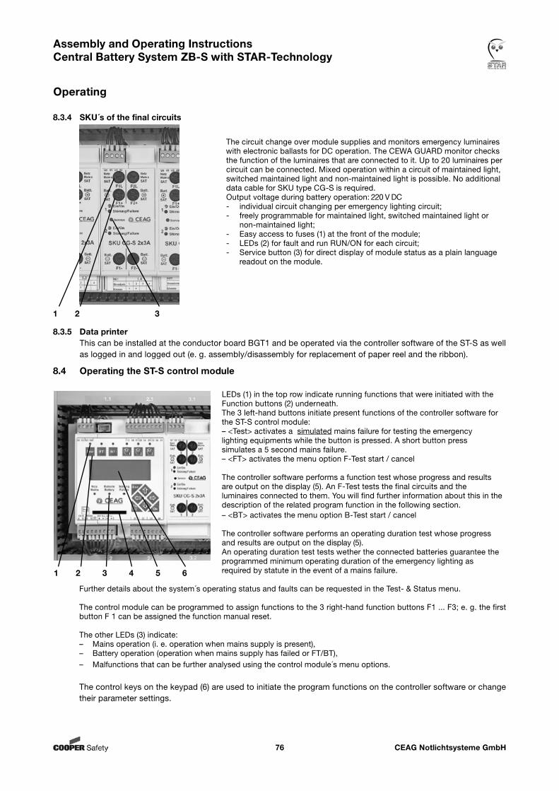
CEAG Notlichtsysteme GmbH76
Assembly and Operating Instructions Central Battery System ZB-S with STAR-Technology
Operating
8.3.4 SKU´s of the final circuits
8.3.5 Data printerThis can be installed at the conductor board BGT1 and be operated via the controller software of the ST-S as well as logged in and logged out (e. g. assembly/disassembly for replacement of paper reel and the ribbon).
1 2 3
The circuit change over module supplies and monitors emergency luminaires with electronic ballasts for DC operation. The CEWA GUARD monitor checks the function of the luminaires that are connected to it. Up to 20 luminaires per circuit can be connected. Mixed operation within a circuit of maintained light, switched maintained light and non-maintained light is possible. No additional data cable for SKU type CG-S is required.Output voltage during battery operation: 220 V DC- individual circuit changing per emergency lighting circuit;- freely programmable for maintained light, switched maintained light or
non-maintained light;- Easy access to fuses (1) at the front of the module;- LEDs (2) for fault and run RUN/ON for each circuit;- Service button (3) for direct display of module status as a plain language
readout on the module.
1 2 3 4 5 6
LEDs (1) in the top row indicate running functions that were initiated with the Function buttons (2) underneath. The 3 left-hand buttons initiate present functions of the controller software for the ST-S control module: – <Test> activates a simulated mains failure for testing the emergency
lighting equipments while the button is pressed. A short button press simulates a 5 second mains failure.
– <FT> activates the menu option F-Test start / cancel
The controller software performs a function test whose progress and results are output on the display (5). An F-Test tests the final circuits and the luminaires connected to them. You will find further information about this in the description of the related program function in the following section.
– <BT> activates the menu option B-Test start / cancel
The controller software performs an operating duration test whose progress and results are output on the display (5). An operating duration test tests wether the connected batteries guarantee the programmed minimum operating duration of the emergency lighting as required by statute in the event of a mains failure.
Further details about the system´s operating status and faults can be requested in the Test- & Status menu.
The control module can be programmed to assign functions to the 3 right-hand function buttons F1 ... F3; e. g. the first button F 1 can be assigned the function manual reset. The other LEDs (3) indicate: – Mains operation (i. e. operation when mains supply is present),– Battery operation (operation when mains supply has failed or FT/BT),– Malfunctions that can be further analysed using the control module´s menu options.
The control keys on the keypad (6) are used to initiate the program functions on the controller software or change their parameter settings.
8.4 Operating the ST-S control module
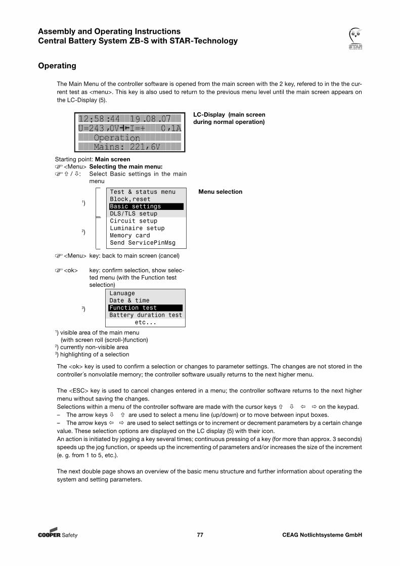
CEAG Notlichtsysteme GmbH77
Assembly and Operating Instructions Central Battery System ZB-S with STAR-Technology
Operating
The Main Menu of the controller software is opened from the main screen with the 2 key, refered to in the the cur-rent test as <menu>. This key is also used to return to the previous menu level until the main screen appears on the LC-Display (5).
The <ok> key is used to confirm a selection or changes to parameter settings. The changes are not stored in the controller´s nonvolatile memory; the controller software usually returns to the next higher menu.
The <ESC> key is used to cancel changes entered in a menu; the controller software returns to the next higher menu without saving the changes. Selections within a menu of the controller software are made with the cursor keys on the keypad. – The arrow keys are used to select a menu line (up/down) or to move between input boxes. – The arrow keys are used to select settings or to increment or decrement parameters by a certain change value. These selection options are displayed on the LC display (5) with their icon. An action is initiated by jogging a key several times; continuous pressing of a key (for more than approx. 3 seconds) speeds up the jog function, or speeds up the incrementing of parameters and/or increases the size of the increment (e. g. from 1 to 5, etc.).
The next double page shows an overview of the basic menu structure and further information about operating the system and setting parameters.
Starting point: Main screen<Menu> Selecting the main menu: / : Select Basic settings in the main
menu
1)
2)
<Menu> key: back to main screen (cancel)
<ok> key: confirm selection, show selec-ted menu (with the Function test selection)
3)
1) visible area of the main menu (with screen roll (scroll-)function)
2) currently non-visible area3) highlighting of a selection
LC-Display (main screen during normal operation)
Menu selection
LanuageDate & timeFunction testBattery duration test
etc...
Test & status menuBlock,resetBasic settingsDLS/TLS setupCircuit setupLuminaire setupMemory cardSend ServicePinMsg
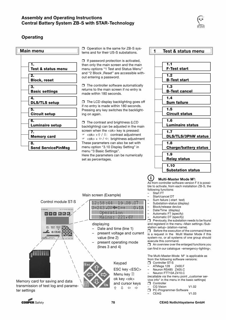
CEAG Notlichtsysteme GmbH78
Assembly and Operating Instructions Central Battery System ZB-S with STAR-Technology
Operating
displaying– Date and time (line 1)– present voltage and current value (line 2)– present operating mode (lines 3 and 4)
Keypad
ESC key <ESC>Menu key ok key <ok>and cursor keys
Memory card for saving and data transmission of test log and parame-ter settings
Control module ST-S
1 Test & status menu
1.1 F-Test start
1.2 B-Test start
1.3 B-Test cancel
1.4 Sum failure
1.5 Circuit status
1.6 Luminaire status
1.7 DLS/TLS/3PhW status
1.8 Charge/battery status
1.9 Relay status
1.10 Substation status
Main menu
Main screen (Example)
1. Test & status menu
2. Block, reset
3. Basic settings
4. DLS/TLS setup
5. Circuit setup
6. Luminaire setup
7. Memory card
8. Send ServicePinMsg
Multi-Master Mode M3:As from controller software version F it is possi-ble to activate, from each installation ZB-S, the following functions:– Start FT – Start/cancel DT – Sum failure (-start test)– Substation-status (display)– Block/release device– Date/Time (display)– Automatic FT (specify)– Automatic DT (specify) Previously, the substation needs to be found and registerd in the menu «Main settings /Sub-station setup» (station-name). Before the execution of the command there is a request in the Mulit Master Mode if this system-no. or all systems of one group should execute this command. An overview over the enlarged functions you can find in our catalogue «emergency-lighting».
Operation is the same for ZB-S sys-tems and for their US-S substations.
If password protection is activated, then only the main screen and the main menu options “1 Test and Status Menu” and “2 Block ,Reset” are accessible with-out entering a password.
The controller software automatically returns to the main screen if no entry is made within 180 seconds.
The LCD display backlighting goes off if no entry is made within 180 seconds. Pressing any key switches the backlight-ing on again.
The contrast and brightness (LCD backlighting) can be adjusted in the main screen when the <ok> key is pressed: <ok> + / : contrast adjustment <ok> + / : brightness adjustmentThese parameters can also be set with menu option “3.10 Display Setting” in menu “3 Basic Settings”. Here the parameters can be numerically set as percentages.
The Multi-Master-Mode M3 is applicable as from the following software versions: Controller ST-S– ATMega 128 Z400.F – Neuron RS485 Z405.C– Neuron FTT10A Z410.C(recallable via the menu point „customer ser-vice info“ in the menu in the basic settings) Controller – CG Vision V1.02 PC-Programmer-Software – CEAG V1.03
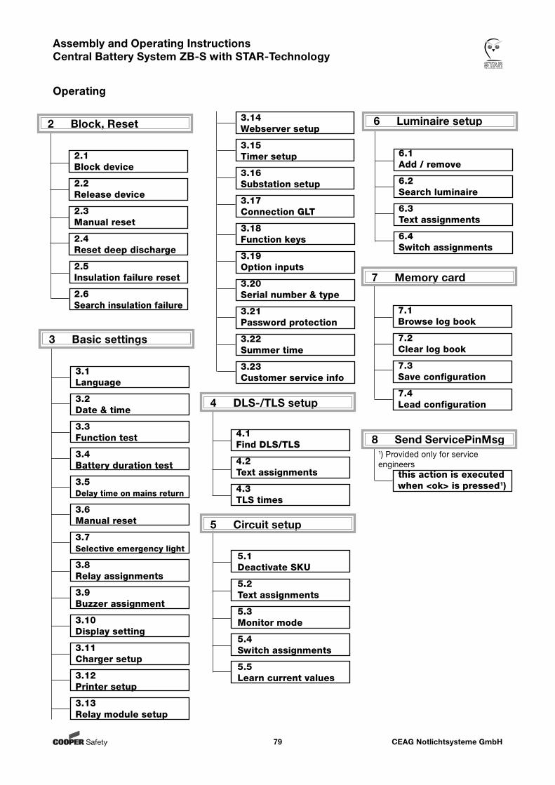
CEAG Notlichtsysteme GmbH79
Assembly and Operating Instructions Central Battery System ZB-S with STAR-Technology
Operating
7 Memory card
7.1 Browse log book
7.2 Clear log book
7.3 Save configuration
7.4 Lead configuration4 DLS-/TLS setup
4.1 Find DLS/TLS
4.2 Text assignments
4.3 TLS times
5 Circuit setup
5.1 Deactivate SKU
5.2 Text assignments
5.3 Monitor mode
5.4 Switch assignments
5.5 Learn current values
3 Basic settings
3.1 Language
3.2 Date & time
3.3 Function test
3.4 Battery duration test
3.5 Delay time on mains return
3.6 Manual reset
3.7 Selective emergency light
3.8 Relay assignments
3.9 Buzzer assignment
3.10 Display setting
3.11 Charger setup
3.12 Printer setup
3.13 Relay module setup
6 Luminaire setup
6.1 Add / remove
6.2 Search luminaire
6.3 Text assignments
6.4 Switch assignments
2 Block, Reset
2.1 Block device
2.2 Release device
2.3 Manual reset
2.4 Reset deep discharge
2.5 Insulation failure reset
2.6 Search insulation failure
8 Send ServicePinMsg
this action is executed when <ok> is pressed1)
1) Provided only for service engineers
3.14 Webserver setup
3.15 Timer setup
3.16 Substation setup
3.17 Connection GLT
3.18 Function keys
3.19 Option inputs
3.20 Serial number & type
3.21 Password protection
3.22 Summer time
3.23 Customer service info
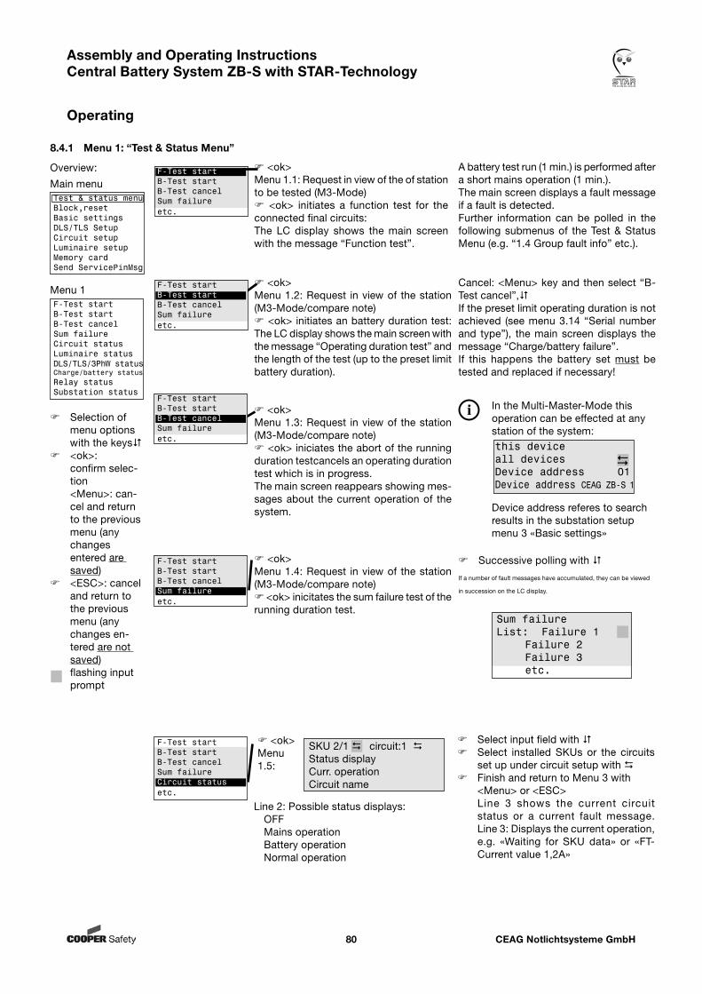
CEAG Notlichtsysteme GmbH80
Assembly and Operating Instructions Central Battery System ZB-S with STAR-Technology
Operating
<ok> Menu 1.1: Request in view of the of station to be tested (M3-Mode) <ok> initiates a function test for the connected final circuits:The LC display shows the main screen with the message “Function test”.
<ok>Menu 1.2: Request in view of the station (M3-Mode/compare note) <ok> initiates an battery duration test: The LC display shows the main screen with the message “Operating duration test” and the length of the test (up to the preset limit battery duration).
<ok>Menu 1.3: Request in view of the station (M3-Mode/compare note) <ok> iniciates the abort of the running duration testcancels an operating duration test which is in progress.The main screen reappears showing mes-sages about the current operation of the system.
A battery test run (1 min.) is performed after a short mains operation (1 min.).The main screen displays a fault message if a fault is detected. Further information can be polled in the following submenus of the Test & Status Menu (e.g. “1.4 Group fault info” etc.).
<ok>Menu 1.4: Request in view of the station (M3-Mode/compare note) <ok> inicitates the sum failure test of the running duration test.
Cancel: <Menu> key and then select “B-Test cancel”,If the preset limit operating duration is not achieved (see menu 3.14 “Serial number and type”), the main screen displays the message “Charge/battery failure”. If this happens the battery set must be tested and replaced if necessary!
Select input field with Select installed SKUs or the circuits
set up under circuit setup with Finish and return to Menu 3 with
<Menu> or <ESC> Line 3 shows the current circuit
status or a current fault message. Line 3: Displays the current operation, e.g. «Waiting for SKU data» or «FT-Current value 1,2A»
<ok>Menu 1.5:
Line 2: Possible status displays: OFF Mains operation Battery operation Normal operation
F-Test startB-Test startB-Test cancelSum failureetc.
F-Test startB-Test startB-Test cancelSum failureetc.
F-Test startB-Test startB-Test cancelSum failureetc.
F-Test startB-Test startB-Test cancelSum failureetc.
F-Test startB-Test startB-Test cancelSum failureCircuit statusetc.
Successive polling with
If a number of fault messages have accumulated, they can be viewed
in succession on the LC display.
SKU 2/1 circuit:1 Status displayCurr. operationCircuit name
Sum failure List: Failure 1 Failure 2 Failure 3 etc.
In the Multi-Master-Mode this operation can be effected at any station of the system:
Device address referes to search results in the substation setup menu 3 «Basic settings»
this deviceall devicesDevice address 01 Device address CEAG ZB-S 1
Overview:
Main menuTest & status menuBlock,resetBasic settingsDLS/TLS SetupCircuit setupLuminaire setupMemory cardSend ServicePinMsg
Menu 1F-Test startB-Test startB-Test cancelSum failureCircuit statusLuminaire statusDLS/TLS/3PhW statusCharge/battery statusRelay statusSubstation status
Selection of menu options with the keys
<ok>: confirm selec-tion
<Menu>: can-cel and return to the previous menu (any changes entered are saved)
<ESC>: cancel and return to the previous menu (any changes en-tered are not saved)
flashing input prompt
8.4.1 Menu 1: “Test & Status Menu”
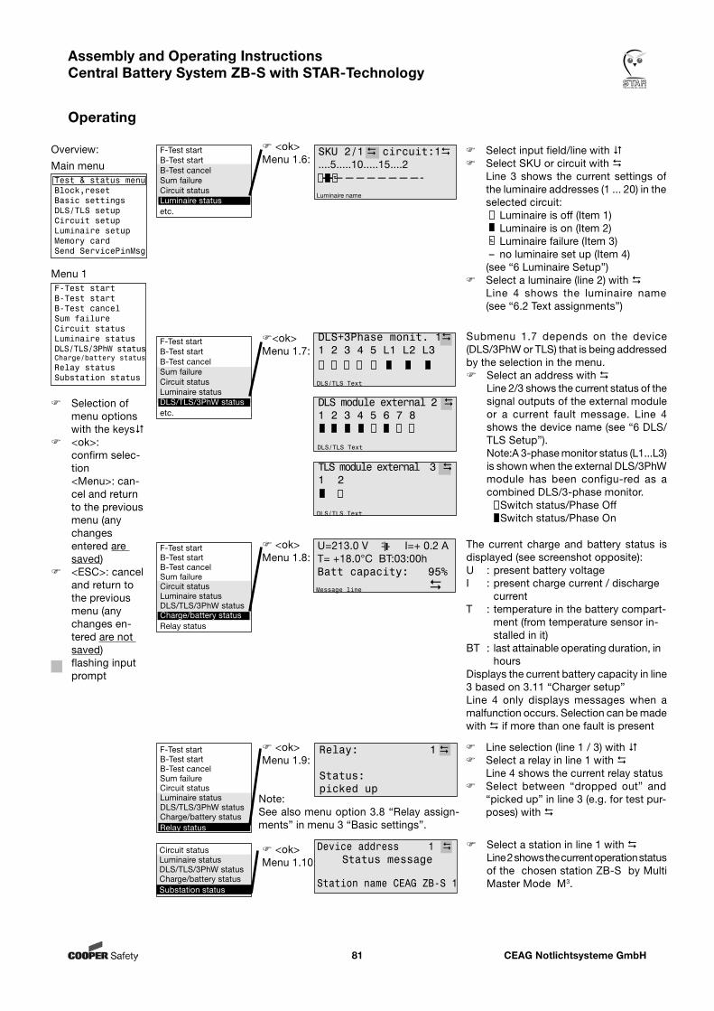
CEAG Notlichtsysteme GmbH81
Assembly and Operating Instructions Central Battery System ZB-S with STAR-Technology
Operating
Line selection (line 1 / 3) with Select a relay in line 1 with Line 4 shows the current relay status Select between “dropped out” and
“picked up” in line 3 (e.g. for test pur-poses) with
Relay: 1
Status: picked up
The current charge and battery status is displayed (see screenshot opposite):U : present battery voltageI : present charge current / discharge
currentT : temperature in the battery compart-
ment (from temperature sensor in- stalled in it)
BT : last attainable operating duration, in hours
Displays the current battery capacity in line 3 based on 3.11 “Charger setup”Line 4 only displays messages when a malfunction occurs. Selection can be made with if more than one fault is present
<ok>Menu 1.9:
U=213.0 V I=+ 0.2 A T= +18.0°C BT:03:00hBatt capacity: 95%
Message line
<ok>Menu 1.8:
<ok> Menu 1.7:
<ok>Menu 1.6:
F-Test startB-Test startB-Test cancelSum failureCircuit statusLuminaire statusetc.
SKU 2/1 circuit:1....5.....10.....15....2—-————————-
Luminaire name
DLS module external 2 1 2 3 4 5 6 7 8
DLS/TLS Text
TLS module external 3 1 2
DLS/TLS Text
Submenu 1.7 depends on the device (DLS/3PhW or TLS) that is being addressed by the selection in the menu. Select an address with Line 2/3 shows the current status of the
signal outputs of the external module or a current fault message. Line 4 shows the device name (see “6 DLS/TLS Setup”).
Note:A 3-phase monitor status (L1...L3) is shown when the external DLS/3PhW module has been configu-red as a combined DLS/3-phase monitor.
Switch status/Phase Off Switch status/Phase On
Select input field/line with Select SKU or circuit with Line 3 shows the current settings of
the luminaire addresses (1 ... 20) in the selected circuit:
Luminaire is off (Item 1) Luminaire is on (Item 2) Luminaire failure (Item 3) – no luminaire set up (Item 4)
(see “6 Luminaire Setup”) Select a luminaire (line 2) with Line 4 shows the luminaire name
(see “6.2 Text assignments”)
F-Test startB-Test startB-Test cancelSum failureCircuit statusLuminaire statusDLS/TLS/3PhW statusCharge/battery statusRelay status
F-Test startB-Test startB-Test cancelSum failureCircuit statusLuminaire statusDLS/TLS/3PhW statusCharge/battery statusRelay status
DLS+3Phase monit. 11 2 3 4 5 L1 L2 L3
DLS/TLS Text
Overview:
Main menuTest & status menuBlock,resetBasic settingsDLS/TLS setupCircuit setupLuminaire setupMemory cardSend ServicePinMsg
Menu 1F-Test startB-Test startB-Test cancelSum failureCircuit statusLuminaire statusDLS/TLS/3PhW statusCharge/battery statusRelay statusSubstation status
Selection of menu options with the keys
<ok>: confirm selec-tion
<Menu>: can-cel and return to the previous menu (any changes entered are saved)
<ESC>: cancel and return to the previous menu (any changes en-tered are not saved)
flashing input prompt
F-Test startB-Test startB-Test cancelSum failureCircuit statusLuminaire statusDLS/TLS/3PhW statusetc.
Note: See also menu option 3.8 “Relay assign-ments” in menu 3 “Basic settings”.
Circuit statusLuminaire statusDLS/TLS/3PhW statusCharge/battery statusSubstation status
<ok>Menu 1.10:
Device address 1 Status message
Station name CEAG ZB-S 1
Select a station in line 1 with Line 2 shows the current operation status
of the chosen station ZB-S by Multi Master Mode M3.
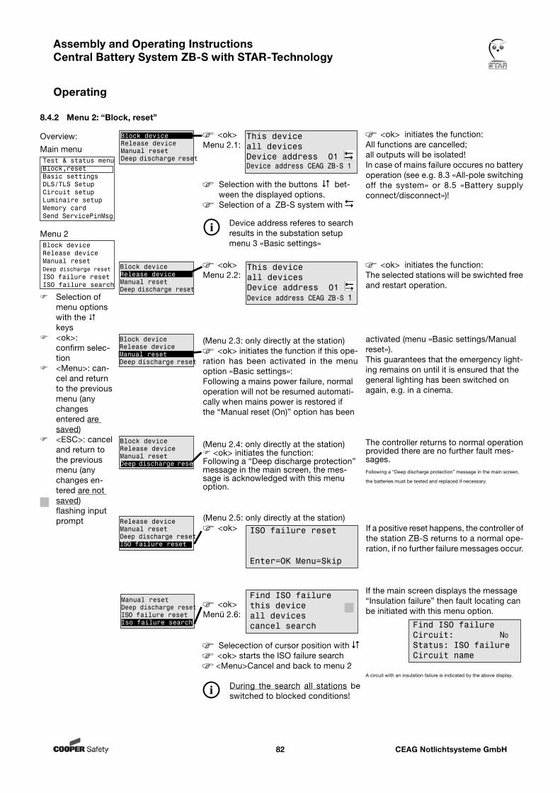
CEAG Notlichtsysteme GmbH82
Assembly and Operating Instructions Central Battery System ZB-S with STAR-Technology
Operating
If the main screen displays the message “Insulation failure” then fault locating can be initiated with this menu option.
A circuit with an insulation failure is indicated by the above display.
8.4.2 Menu 2: “Block, reset”
Overview:
Main menuTest & status menuBlock,resetBasic settingsDLS/TLS SetupCircuit setupLuminaire setupMemory cardSend ServicePinMsg
Menu 2Block deviceRelease deviceManual resetDeep discharge resetISO failure resetISO failure search
Selection of menu options with the keys
<ok>: confirm selec-tion
<Menu>: can-cel and return to the previous menu (any changes entered are saved)
<ESC>: cancel and return to the previous menu (any changes en-tered are not saved)
flashing input prompt
<ok>Menu 2.1:
(Menu 2.4: only directly at the station) <ok> initiates the function:Following a “Deep discharge protection” message in the main screen, the mes-sage is acknowledged with this menu option.
(Menu 2.3: only directly at the station) <ok> initiates the function if this ope-
ration has been activated in the menu option «Basic settings»:Following a mains power failure, normal operation will not be resumed automati-cally when mains power is restored if the “Manual reset (On)” option has been
Block deviceRelease deviceManual resetDeep discharge reset
ISO failure reset
Enter=OK Menu=Skip
(Menu 2.5: only directly at the station) <ok>
Find ISO failureCircuit: NoStatus: ISO failureCircuit name
Block deviceRelease deviceManual resetDeep discharge reset
Release deviceManual resetDeep discharge resetISO failure reset
Block deviceRelease deviceManual resetDeep discharge reset
This deviceall devicesDevice address 01 Device address CEAG ZB-S 1
Block deviceRelease deviceManual resetDeep discharge reset
<ok> initiates the function:The selected stations will be swichted free and restart operation.
activated (menu «Basic settings/Manual reset»).This guarantees that the emergency light-ing remains on until it is ensured that the general lighting has been switched on again, e.g. in a cinema.
Find ISO failurethis deviceall devices cancel search
<ok>Menü 2.6:
Manual resetDeep discharge resetISO failure resetIso failure search
Selection with the buttons bet-ween the displayed options.Selection of a ZB-S system with
Device address referes to search results in the substation setup menu 3 «Basic settings»
Selecection of cursor position with <ok> starts the ISO failure search <Menu>Cancel and back to menu 2
<ok>Menu 2.2:
This deviceall devicesDevice address 01 Device address CEAG ZB-S 1
If a positive reset happens, the controller of the station ZB-S returns to a normal ope-ration, if no further failure messages occur.
<ok> initiates the function:All functions are cancelled; all outputs will be isolated! In case of mains failure occures no battery operation (see e.g. 8.3 «All-pole switching off the system» or 8.5 «Battery supply connect/disconnect»)!
During the search all stations be switched to blocked conditions!
The controller returns to normal operation provided there are no further fault mes-sages.Following a “Deep discharge protection” message in the main screen,
the batteries must be tested and replaced if necessary.

CEAG Notlichtsysteme GmbH83
Assembly and Operating Instructions Central Battery System ZB-S with STAR-Technology
Operating
Setting the system time (current date and time) for the internal clock of the ST-S control module.
Use the keys to toggle between “Language: National language” 2)
and “Language: english” Finish and return to Menu 3 with
<Menu>
2) Can only be selected when memory card is inserted.
Setting the start (date and time) of the first function test and the intervals (1 to 14 days) of subsequent function tests (factory setting: all 7 days).Setting the start-up time of the FT in 5s steps (factory setting: 300s)For all luminaires with “End of line” cut off (EoL).With function key 3 a FT without start-up time can be started.
Setting the start (date and time) of the first battery duration test and the inter-vals (1 ... 12 months) of subsequent battery duration tests.
8.4.3 Menu 3: “Basic settings”
<ok> The currently selectedMenu 3.1: language is displayed 1)
1) Setting on delivery/initial commission-ing
<ok>Menu 3.2:
<ok>Menu 3.3:
<ok>Menu 3.4:
LanguageDate & timeFunction testBattery duration testetc....
LanguageDate & timeFunction testBattery duration testetc....
LanguageDate & timeFunction testBattery duration testetc....
Important note!These settings are the basis for all log book entries and (synchronised) test of the system!
Overview:
Main menuTest & status menuBlock,resetBasic settingsDLS/TLS SetupCircuit setupLuminaire setupMemory cardSend ServicePinMsg
Menu 3LanguageDate & timeFunction testBattery duration testDelay on mains returnManual resetSelective emerg lightRelay assignmentsBuzzer assignmentDisplay settingCharger setupPrinter setupRelay module setupWebserver setupTimer setupSubstation setupConnection BMSFunction keysOption inputsSerial number & typePassword protectionSummertimeCustomer service info
Selection of menu options with the keys
<ok>: confirm selec-tion
<Menu>: can-cel and return to the previous menu (any changes entered are saved)
<ESC>: cancel and return to the previous menu (any changes en-tered are not saved)
flashing input prompt
LanguageDate & timeFunction testBattery duration testetc....
Date & TimeWe 11.12.07 12:00
ZB-S autosync.: yes
F-Test Date&TimeWe 11.12.07 12:00FT start-up time 300s
Interval in days: 01
B-Test Date&TimeWe 11.12.07 12:00
Interval in months: 12
Note!Fall back language for controller reset or after the installation of a new ST-S is allways english
Select the date and time positions (^^) with
Change with and start the clock of the ST-S controller with <Menu>
Finish with <Menu>This request follows:
Enter “OK” synchronises the clock of all connected substations in one group
Substationsynchronise ?
Menu = no OK = yes
Substationsynchronise ?
Menu = no OK = yes
Substationsynchronise ?
Menu = no OK = yes
Select the input position for date, time, intervals (in days) and FT start-up time (in 5s) with
Change with Finish with <Menu>This request follows:
Select the input position (^^) for date, time and interval (in months) with
Change with Finish with <Menu>This request follows:
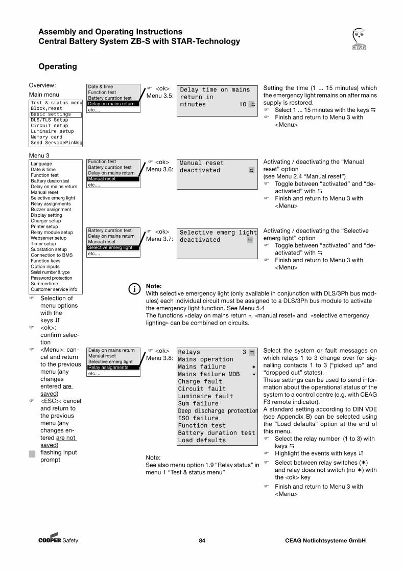
CEAG Notlichtsysteme GmbH84
Assembly and Operating Instructions Central Battery System ZB-S with STAR-Technology
Operating
Select the system or fault messages on which relays 1 to 3 change over for sig-nalling contacts 1 to 3 (“picked up” and “dropped out” states). These settings can be used to send infor-mation about the operational status of the system to a control centre (e.g. with CEAG F3 remote indicator).A standard setting according to DIN VDE (see Appendix B) can be selected using the “Load defaults” option at the end of this menu. Select the relay number (1 to 3) with
keys Highlight the events with keys
Select between relay switches () and relay does not switch (no ) with the <ok> key
Finish and return to Menu 3 with <Menu>
Activating / deactivating the “Manual reset” option(see Menu 2.4 “Manual reset”) Toggle between “activated” and “de-
activated” with Finish and return to Menu 3 with
<Menu>
<ok>Menu 3.6:
<ok>Menu 3.8:
Setting the time (1 ... 15 minutes) which the emergency light remains on after mains supply is restored. Select 1 ... 15 minutes with the keys Finish and return to Menu 3 with
<Menu>
<ok>Menu 3.5:
Date & timeFunction testBattery duration testDelay on mains returnetc....
Function testBattery duration testDelay on mains returnManual resetetc....
Delay on mains returnManual resetSelective emerg lightRelay assignmentsetc....
Manual resetdeactivated
Delay time on mains return in minutes 10
Activating / deactivating the “Selective emerg light” option Toggle between “activated” and “de-
activated” with Finish and return to Menu 3 with
<Menu>
<ok>Menu 3.7:
Battery duration testDelay on mains returnManual resetSelective emerg lightetc....
Note:See also menu option 1.9 “Relay status” in menu 1 “Test & status menu”.
Selective emerg lightdeactivated
Relays 3 Mains operation Mains failure Mains failure MDB Charge faultCircuit faultLuminaire faultSum failureDeep discharge protectionISO failureFunction testBattery duration testLoad defaults
Note:With selective emergency light (only available in conjunction with DLS/3Ph bus mod-ules) each individual circuit must be assigned to a DLS/3Ph bus module to activate the emergency light function. See Menu 5.4The functions «delay on mains return », «manual reset» and «selective emergency lighting» can be combined on circuits.
Overview:
Main menuTest & status menuBlock,resetBasic settingsDLS/TLS SetupCircuit setupLuminaire setupMemory cardSend ServicePinMsg
Menu 3LanguageDate & timeFunction testBattery duration testDelay on mains returnManual resetSelective emerg lightRelay assignmentsBuzzer assignmentDisplay settingCharger setupPrinter setupRelay module setupWebserver setupTimer setupSubstation setupConnection to BMSFunction keysOption inputsSerial number & typePassword protectionSummertimeCustomer service info
Selection of menu options with the keys
<ok>: confirm selec-tion
<Menu>: can-cel and return to the previous menu (any changes entered are saved)
<ESC>: cancel and return to the previous menu (any changes en-tered are not saved)
flashing input prompt
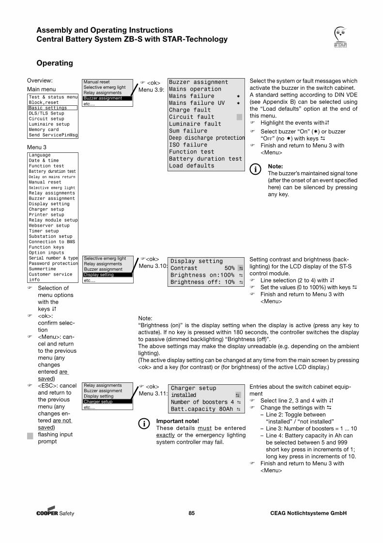
CEAG Notlichtsysteme GmbH85
Assembly and Operating Instructions Central Battery System ZB-S with STAR-Technology
Operating
<ok>Menu 3.9:
Select the system or fault messages which activate the buzzer in the switch cabinet. A standard setting according to DIN VDE (see Appendix B) can be selected using the “Load defaults” option at the end of this menu. Highlight the events with
Select buzzer “On” () or buzzer “oFF” (no ) with keys
Finish and return to Menu 3 with <Menu>
Note:The buzzer’s maintained signal tone (after the onset of an event specified here) can be silenced by pressing any key.
Note:“Brightness (on)” is the display setting when the display is active (press any key to activate). If no key is pressed within 180 seconds, the controller switches the display to passive (dimmed backlighting) “Brightness (off)”.The above settings may make the display unreadable (e.g. depending on the ambient lighting). (The active display setting can be changed at any time from the main screen by pressing <ok> and a key (for contrast) or (for brightness) of the active LCD display.)
Setting contrast and brightness (back-lighting) for the LCD display of the ST-S control module. Line selection (2 to 4) with Set the values (0 to 100%) with keys Finish and return to Menu 3 with
<Menu>
<ok>Menu 3.10:
Manual resetSelective emerg lightRelay assignmentsBuzzer assignmentetc....
Selective emerg lightRelay assignmentsBuzzer assignmentDisplay settingetc....
Display settingContrast 50% Brightness on:100% Brightness off: 10%
Buzzer assignmentMains operation Mains failure Mains failure UV Charge faultCircuit faultLuminaire faultSum failureDeep discharge protectionISO failureFunction testBattery duration testLoad defaults
Overview:
Main menuTest & status menuBlock,resetBasic settingsDLS/TLS SetupCircuit setupLuminaire setupMemory cardSend ServicePinMsg
Menu 3LanguageDate & timeFunction testBattery duration testDelay on mains returnManual resetSelective emerg lightRelay assignmentsBuzzer assignmentDisplay settingCharger setupPrinter setupRelay module setupWebserver setupTimer setupSubstation setupConnection to BMSFunction keysOption inputsSerial number & typePassword protectionSummertimeCustomer service info
Selection of menu options with the keys
<ok>: confirm selec-tion
<Menu>: can-cel and return to the previous menu (any changes entered are saved)
<ESC>: cancel and return to the previous menu (any changes en-tered are not saved)
flashing input prompt
Entries about the switch cabinet equip-ment Select line 2, 3 and 4 with Change the settings with
– Line 2: Toggle between “installed” / “not installed”
– Line 3: Number of boosters = 1 ... 10– Line 4: Battery capacity in Ah can
be selected between 5 and 999 short key press in increments of 1; long key press in increments of 10.
Finish and return to Menu 3 with <Menu>
<ok>Menu 3.11:
Relay assignmentsBuzzer assignmentDisplay settingCharger setupetc....
Important note!These details must be entered exactly or the emergency lighting system controller may fail.
Charger setupinstalled Number of boosters 4 Batt.capacity 80Ah
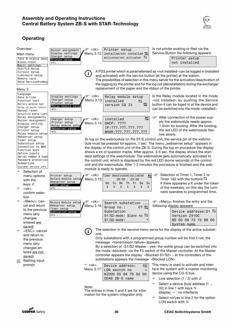
CEAG Notlichtsysteme GmbH86
Assembly and Operating Instructions Central Battery System ZB-S with STAR-Technology
Operating
Buzzer assignmentDisplay settingsCharger setupPrinter setupetc....
<ok>Menu 3.12:
Printer setupinstalled/not installed activated/not activated
Is not printer existing or filed via the Service-Button the following appears:
Printer setupnot installed
A PD3 printer which is parameterised as «not installed» can be logged in (installed and activated) with the service button (at the printer) at the station.The possibilities of selection in this menu server for the activation/deactivation of the logging by the printer and for the log out (deinstallation) during the exchange/replacement of the paper and the ribbon of the printer.
Display settingsCharger setupPrinter setupRelay module setupetc....
<ok>Menu 3.13:
Relay module setupinstalled version CG IV
Is the Relay module located in the mode «not installed» by pushing the Service button it can be loged in at the device and can be switched into the mode «installed».
Charger setupPrinter setupRelay module setupWebserver setupetc....
<ok>Menu 3.15:
Timer deactivated/activated00:00 - 23:59
Mo Tu We Th Fr Sa SuX X X X X X X
Selection of Timer 1, Timer 2 or Timer 1&2 with the buttons
If there appeares a X under the token of the weekday, on this day the lumi-naire operates to programmed time.
Printer setupRelais module setupWebserver setupTimer setupetc....
<ok>Menu 3.16:
Search substation ...Group no.: 07 SubstationS1/S2-mode: Slave no S1/S2-mode: *
<Menu> finishes the entry and the following display appears:
Device addresse:01 Version Z410CND 00 09 73 72 96 00System name
The selection in the second menu serve for the display of the active substati-ons.Only substations with a programmed group number will be find if not, the message «transmission failure» appears.By a selection of «S1/S2-Master - yes» the wohle group can be switched into the mode «blocked» via the F3-switch of the Master controller. At the Master controller appears the display «Blocked S1/S2» – at the controllers of the substations appears the message «Blocked LON»
Overview:
Main menuTest & status menuBlock,resetBasic settingsDLS/TLS SetupCircuit setupLuminaire setupMemory cardSend ServicePinMsg
Menu 3LanguageDate & timeFunction testBattery duration testDelay on mains returnManual resetSelective emerg lightRelay assignmentsBuzzer assignmentDisplay settingCharger setupPrinter setupRelay module setupWebserver setupTimer setupSubstation setupConnection to BMSFunction keysOption inputsSerial number & typePassword protectionSummertimeCustomer service info
Selection of menu options with the keys
<ok>: confirm selec-tion
<Menu>: can-cel and return to the previous menu (any changes entered are saved)
<ESC>: cancel and return to the previous menu (any changes en-tered are not saved)
flashing input prompt <ok>
Menu 3.17:This menu is used to activate and inter-face the system with a master monitoring device using the CG-S bus.
Line selection (1 / 2) with
Select a device (bus) address (1 ... 32) in line 1 with keys (display — : no interface)
Select no/yes in line 2 for the option LON switch with
Note:The entries in lines 3 and 4 are for infor-mation for the system integrator only.
Device address: 1LON switch no NID00 05 94 75 52 00CEAG ZB-S name
Relais module setupWebserver setupTimer setupSubstation setupetc....
<ok>Menu 3.14:
installed DHCP: ????IP:???.???.???.???MASK:???.???.???.???
After connection of the power sup-ply the webmodule needs approx. 1.5min for booting. After the booting, the red LED of the webmodule flas-hes slowly.
To log on the webmodule on the ST-S control unit, the service pin of the webmo-dule must be pressed for approx. 1 sec. The menu „webserver setup“ appears in the display of the control unit of the ZB-S. During the log on procedure the display shows a lot of question marks. After approx. 3-5 sec. the display shows the stan-dard settings of the webmodule: The webmodule gets automatically activated to the control unit, which is displayed by the red LED (some seconds) of the control unit and the webmodule. After 1-2 minutes the procedure is finished and the web-module is ready to operate.
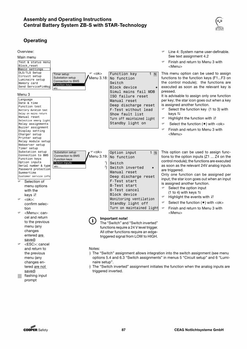
CEAG Notlichtsysteme GmbH87
Assembly and Operating Instructions Central Battery System ZB-S with STAR-Technology
Operating
This menu option can be used to assign functions to the function keys (F1...F3 on the control module); the functions are executed as soon as the relevant key is pressed. It is advisable to assign only one function per key; the star icon goes out when a key is assigned another function. Select the function key (1 to 3) with
keys Highlight the function with
Select the function () with <ok>
Finish and return to Menu 3 with <Menu>
Timer setupSubstation setupConnection to BMSFunction keysetc....
This option can be used to assign func-tions to the option inputs (Z1 ... Z4 on the control module); the functions are executed as soon as the relevant 24V analog inputs are triggered. Only one function can be assigned per input; the star icon goes out when an input is assigned another function. Select the option input
(1 to 4) with keys Highlight the events with
Select the function () with <ok>
Finish and return to Menu 3 with <Menu>
Substation setupConnection to BMSFunction keysOption inputsetc....
Notes:1) The “Switch” assignment allows integration into the switch assignment (see menu
options 5.4 and 6.3 “Switch assignments” in menus 5 “Circuit setup” and 6 “Lumi-naire setup”.
2) The “Switch inverted” assignment initiates the function when the analog inputs are triggered inverted.
<ok>Menu 3.18:
Function key 1 No function SwitchBlock device Simul mains fail MDBISO failure resetManual resetDeep discharge resetF-Test without leadShow fault listTurn off maintained lightStandby light on
<ok>Menu 3.19:
SwitchSwitch inverted Manual resetDeep discharge resetF-Test startB-Test startB-Test cancelBlock deviceMonitoring ventilationStandby light off Turn on maintained light
1)2)
Important note!The “Switch” and “Switch inverted” functions require a 24 V level trigger. All other functions require an edge-triggered signal from LOW to HIGH.
Overview:
Main menuTest & status menuBlock,resetBasic settingsDLS/TLS SetupCircuit setupLuminaire setupMemory cardSend ServicePinMsg
Menu 3LanguageDate & timeFunction testBattery duration testDelay on mains returnManual resetSelective emerg lightRelay assignmentsBuzzer assignmentDisplay settingCharger setupPrinter setupRelay module setupWebserver setupTimer setupSubstation setupConnection to BMSFunction keysOption inputsSerial number & typePassword protectionSummertimeCustomer service info
Selection of menu options with the keys
<ok>: confirm selec-tion
<Menu>: can-cel and return to the previous menu (any changes entered are saved)
<ESC>: cancel and return to the previous menu (any changes en-tered are not saved)
flashing input prompt
Option input 1 No function
Line 4: System name user-definable. See text assignment 4.2
Finish and return to Menu 3 with <Menu>
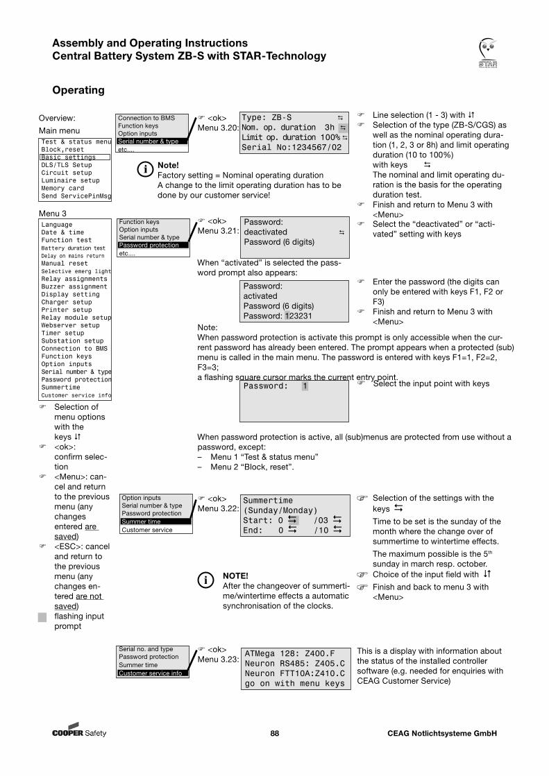
CEAG Notlichtsysteme GmbH88
Assembly and Operating Instructions Central Battery System ZB-S with STAR-Technology
Operating
Password:deactivated Password (6 digits)
<ok>Menu 3.21:
Select the “deactivated” or “acti-vated” setting with keys
Enter the password (the digits can only be entered with keys F1, F2 or F3)
Finish and return to Menu 3 with <Menu>
Note:When password protection is activate this prompt is only accessible when the cur-rent password has already been entered. The prompt appears when a protected (sub)menu is called in the main menu. The password is entered with keys F1=1, F2=2, F3=3; a flashing square cursor marks the current entry point.
When password protection is active, all (sub)menus are protected from use without a password, except:– Menu 1 “Test & status menu”– Menu 2 “Block, reset”.
Function keysOption inputsSerial number & typePassword protectionetc....
Select the input point with keys
<ok>Menu 3.20:
Line selection (1 - 3) with Selection of the type (ZB-S/CGS) as
well as the nominal operating dura-tion (1, 2, 3 or 8h) and limit operating duration (10 to 100%) with keys The nominal and limit operating du-ration is the basis for the operating duration test.
Finish and return to Menu 3 with <Menu>
Connection to BMSFunction keysOption inputsSerial number & typeetc....
Type: ZB-S
Nom. op. duration 3h
Limit op. duration 100%
Serial No:1234567/02
When “activated” is selected the pass-word prompt also appears:
Password:activated Password (6 digits) Password: 123231
Password: 1
<ok>Menu 3.23:
Serial no. and typePassword protectionSummer timeCustomer service info
This is a display with information about the status of the installed controller software (e.g. needed for enquiries with CEAG Customer Service)
ATMega 128: Z400.FNeuron RS485: Z405.CNeuron FTT10A:Z410.Cgo on with menu keys
<ok>Menu 3.22:
Option inputsSerial number & typePassword protectionSummer timeCustomer service
Summertime(Sunday/Monday)Start: 0 /03 End: 0 /10
Selection of the settings with the keys
Time to be set is the sunday of the month where the change over of summertime to wintertime effects.
The maximum possible is the 5th
sunday in march resp. october. Choice of the input field with
Finish and back to menu 3 with <Menu>
NOTE!After the changeover of summerti-me/wintertime effects a automatic synchronisation of the clocks.
Overview:
Main menuTest & status menuBlock,resetBasic settingsDLS/TLS SetupCircuit setupLuminaire setupMemory cardSend ServicePinMsg
Menu 3LanguageDate & timeFunction testBattery duration testDelay on mains returnManual resetSelective emerg lightRelay assignmentsBuzzer assignmentDisplay settingCharger setupPrinter setupRelay module setupWebserver setupTimer setupSubstation setupConnection to BMSFunction keysOption inputsSerial number & typePassword protectionSummertimeCustomer service info
Selection of menu options with the keys
<ok>: confirm selec-tion
<Menu>: can-cel and return to the previous menu (any changes entered are saved)
<ESC>: cancel and return to the previous menu (any changes en-tered are not saved)
flashing input prompt
Note!Factory setting = Nominal operating durationA change to the limit operating duration has to be done by our customer service!
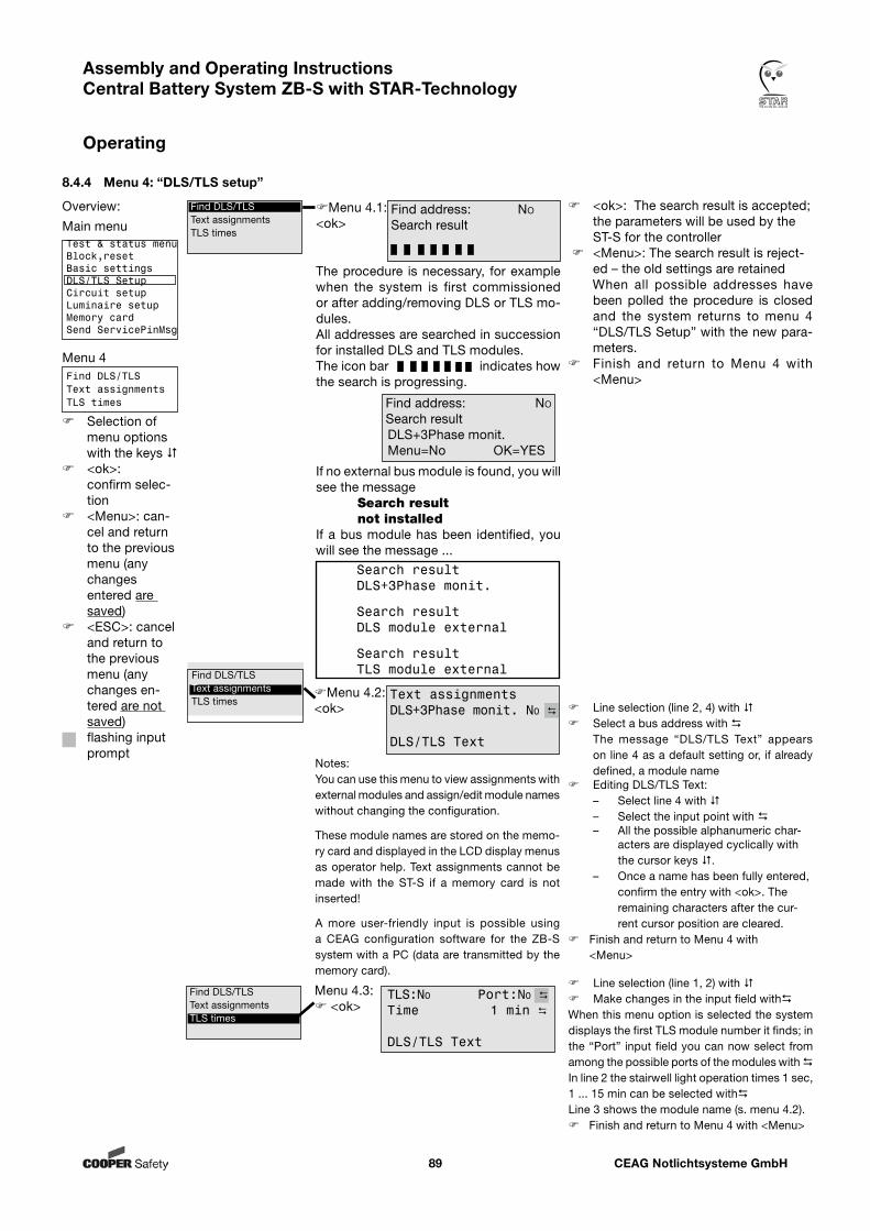
CEAG Notlichtsysteme GmbH89
Assembly and Operating Instructions Central Battery System ZB-S with STAR-Technology
Operating
8.4.4 Menu 4: “DLS/TLS setup”
Menu 4.1:<ok>
<ok>: The search result is accepted; the parameters will be used by the ST-S for the controller
<Menu>: The search result is reject-ed – the old settings are retained
When all possible addresses have been polled the procedure is closed and the system returns to menu 4 “DLS/TLS Setup” with the new para -meters.
Finish and return to Menu 4 with <Menu>
The procedure is necessary, for example when the system is first commissioned or after adding/removing DLS or TLS mo-dules.All addresses are searched in succession for installed DLS and TLS modules.The icon bar indicates how the search is progressing.
Menu 4.2:<ok> Line selection (line 2, 4) with
Select a bus address with The message “DLS/TLS Text” appears
on line 4 as a default setting or, if already defined, a module name
Editing DLS/TLS Text:– Select line 4 with – Select the input point with – All the possible alphanumeric char-
acters are displayed cyclically with the cursor keys .
– Once a name has been fully entered, confirm the entry with <ok>. The remaining characters after the cur-rent cursor position are cleared.
Finish and return to Menu 4 with <Menu>
Find address: no
Search result
Find address: no
Search resultDLS+3Phase monit.Menu=No OK=YES
If no external bus module is found, you will see the message Search result not installed
If a bus module has been identified, you will see the message ...
Search result DLS+3Phase monit.
Search result DLS module external
Search result TLS module external
Find DLS/TLSText assignmentsTLS times
Text assignmentsDLS+3Phase monit. No
DLS/TLS Text
Find DLS/TLSText assignmentsTLS times
Notes:You can use this menu to view assignments with external modules and assign/edit module names without changing the configuration.
These module names are stored on the memo-ry card and displayed in the LCD display menus as operator help. Text assignments cannot be made with the ST-S if a memory card is not inserted!
A more user-friendly input is possible using a CEAG configuration software for the ZB-S system with a PC (data are transmitted by the memory card).
Overview:
Main menuTest & status menuBlock,resetBasic settingsDLS/TLS SetupCircuit setupLuminaire setupMemory cardSend ServicePinMsg
Menu 4Find DLS/TLSText assignmentsTLS times
Selection of menu options with the keys
<ok>: confirm selec-tion
<Menu>: can-cel and return to the previous menu (any changes entered are saved)
<ESC>: cancel and return to the previous menu (any changes en-tered are not saved)
flashing input prompt
Line selection (line 1, 2) with Make changes in the input field withWhen this menu option is selected the system displays the first TLS module number it finds; in the “Port” input field you can now select from among the possible ports of the modules with In line 2 the stairwell light operation times 1 sec, 1 ... 15 min can be selected withLine 3 shows the module name (s. menu 4.2). Finish and return to Menu 4 with <Menu>
Menu 4.3: <ok>
Find DLS/TLSText assignmentsTLS times
TLS:No Port:No Time 1 min
DLS/TLS Text
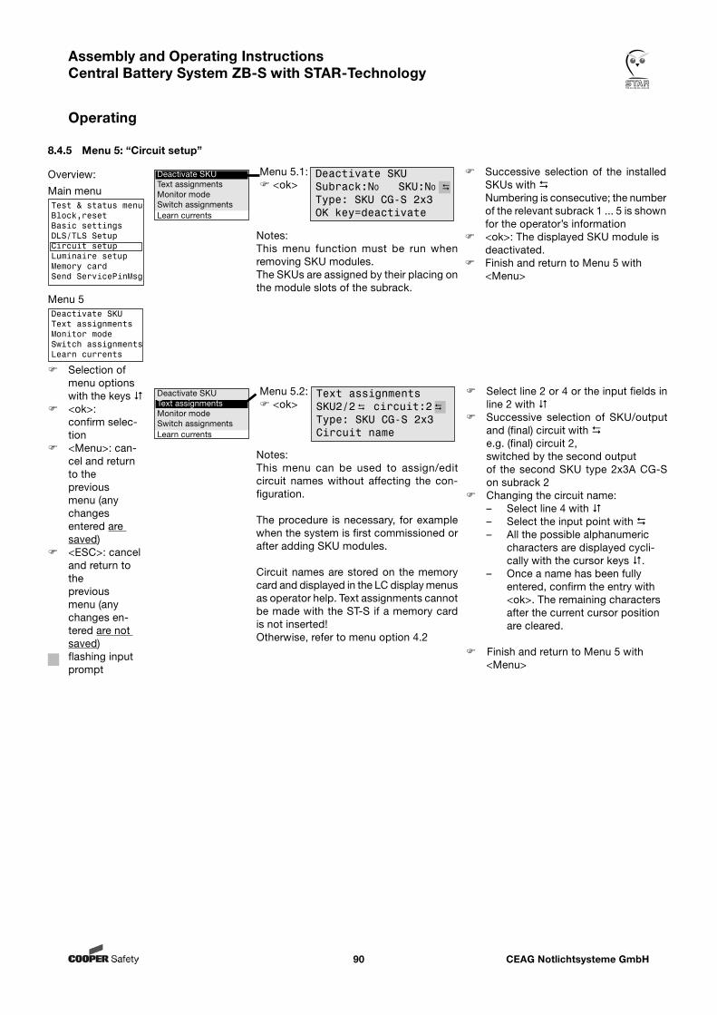
CEAG Notlichtsysteme GmbH90
Assembly and Operating Instructions Central Battery System ZB-S with STAR-Technology
Operating
8.4.5 Menu 5: “Circuit setup”
Menu 5.1: <ok>
Successive selection of the installed SKUs with
Numbering is consecutive; the number of the relevant subrack 1 ... 5 is shown for the operator’s information
<ok>: The displayed SKU module is deactivated.
Finish and return to Menu 5 with <Menu>
Notes:This menu function must be run when removing SKU modules.The SKUs are assigned by their placing on the module slots of the subrack.
Select line 2 or 4 or the input fields in line 2 with
Successive selection of SKU/output and (final) circuit with e.g. (final) circuit 2,
switched by the second output of the second SKU type 2x3A CG-S
on subrack 2 Changing the circuit name:
– Select line 4 with – Select the input point with – All the possible alphanumeric
characters are displayed cycli-cally with the cursor keys .
– Once a name has been fully entered, confirm the entry with <ok>. The remaining characters after the current cursor position are cleared.
Finish and return to Menu 5 with
<Menu>
Deactivate SKUText assignmentsMonitor modeSwitch assignmentsLearn currents
Notes:This menu can be used to assign/edit circuit names without affecting the con-figuration.
The procedure is necessary, for example when the system is first commissioned or after adding SKU modules.
Circuit names are stored on the memory card and displayed in the LC display menus as operator help. Text assignments cannot be made with the ST-S if a memory card is not inserted!Otherwise, refer to menu option 4.2
Deactivate SKUText assignmentsMonitor modeSwitch assignmentsLearn currents
Deactivate SKUSubrack:No SKU:No Type: SKU CG-S 2x3 OK key=deactivate
Overview:
Main menuTest & status menuBlock,resetBasic settingsDLS/TLS SetupCircuit setupLuminaire setupMemory cardSend ServicePinMsg
Menu 5Deactivate SKUText assignmentsMonitor modeSwitch assignmentsLearn currents
Selection of menu options with the keys
<ok>: confirm selec-tion
<Menu>: can-cel and return to the previous menu (any changes entered are saved)
<ESC>: cancel and return to the previous menu (any changes en-tered are not saved)
flashing input prompt
Menu 5.2: <ok>
Text assignmentsSKU2/2 circuit:2
Type: SKU CG-S 2x3 Circuit name
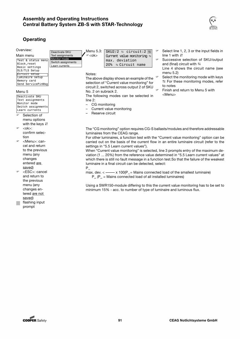
CEAG Notlichtsysteme GmbH91
Assembly and Operating Instructions Central Battery System ZB-S with STAR-Technology
Operating
Overview:
Main menuTest & status menuBlock,resetBasic settingsDLS/TLS SetupCircuit setupLuminaire setupMemory cardSend ServicePinMsg
Menu 5Deactivate SKUText assignmentsMonitor modeSwitch assignmentsLearn currents
Selection of menu options with the keys
<ok>: confirm selec-tion
<Menu>: can-cel and return to the previous menu (any changes entered are saved)
<ESC>: cancel and return to the previous menu (any changes en-tered are not saved)
flashing input prompt
Menu 5.3:<ok>
Select line 1, 2, 3 or the input fields in line 1 with
Successive selection of SKU/output and (final) circuit with Line 4 shows the circuit name (see menu 5.2)
Select the monitoring mode with keys For these monitoring modes, refer to notes
Finish and return to Menu 5 with <Menu>
The “CG monitoring” option requires CG-S ballasts/modules and therefore addressable luminaires from the CEAG range. For other luminaires, a function test with the “Current value monitoring” option can be carried out on the basis of the current flow in an entire luminaire circuit (refer to the settings in “5.5 Learn current values”).When “Current value monitoring” is selected, line 3 prompts entry of the maximum de-viation (1 ... 20%) from the reference value determined in “5.5 Learn current values” at which there is still no fault message in a function test.So that the failure of the weakest luminaire in a final circuit can be detected, select:Pmin max. dev. < ––––– x 100(Pmin = Mains connected load of the smallest luminaire) Pges (Pges = Mains connected load of all installed luminaires)
Using a SWR150-module differing to this the current value monitoring has to be set to minimum 15% - acc. to number of type of luminaire and luminous flux.
Notes:The above display shows an example of the selection of “Current value monitoring” for circuit 2, switched across output 2 of SKU No. 2 on subrack 2.The following modes can be selected in line 2:– CG monitoring– Current value monitoring– Reserve circuit
Deactivate SKUText assignmentsMonitor modeSwitch assignmentsLearn currents
SKU2/2 circuit:2
Current value monitoring max. deviation 20% Circuit name
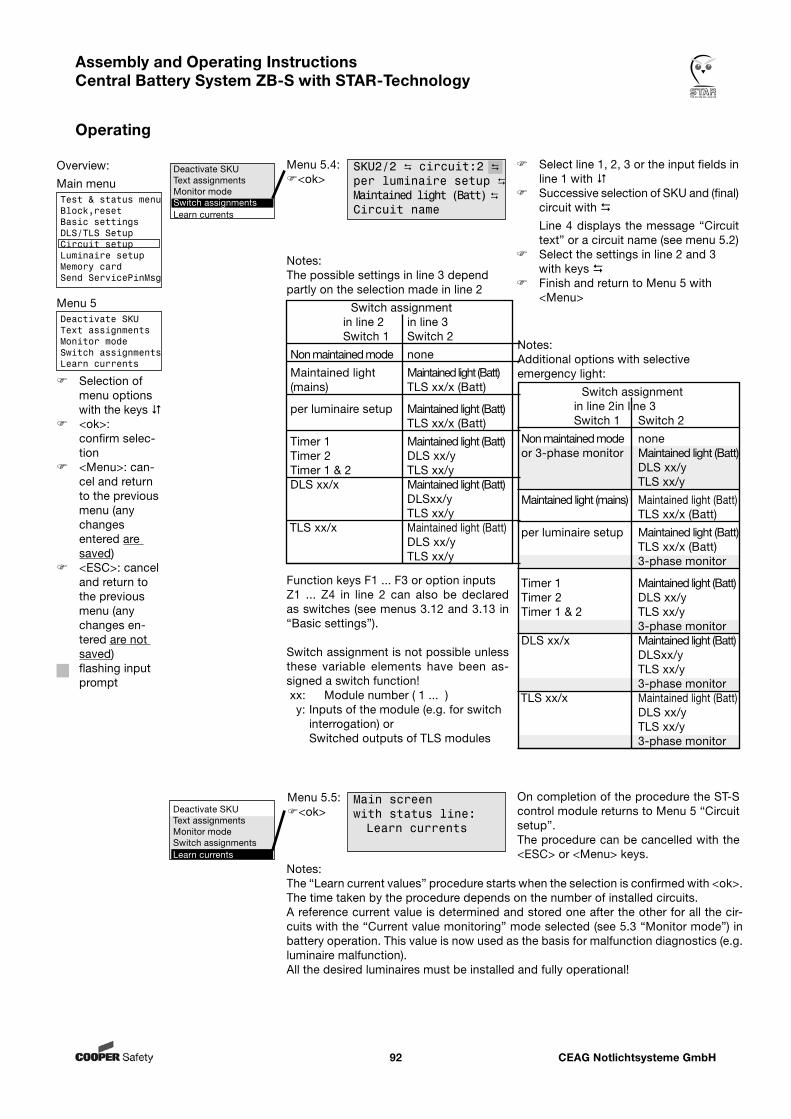
CEAG Notlichtsysteme GmbH92
Assembly and Operating Instructions Central Battery System ZB-S with STAR-Technology
Operating
Menu 5.4:<ok>
Deactivate SKUText assignmentsMonitor modeSwitch assignmentsLearn currents
SKU2/2 circuit:2 per luminaire setup Maintained light (Batt) Circuit name
Select line 1, 2, 3 or the input fields in line 1 with
Successive selection of SKU and (final) circuit with
Line 4 displays the message “Circuit text” or a circuit name (see menu 5.2)
Select the settings in line 2 and 3 with keys Finish and return to Menu 5 with <Menu>
Overview:
Main menuTest & status menuBlock,resetBasic settingsDLS/TLS SetupCircuit setupLuminaire setupMemory cardSend ServicePinMsg
Menu 5Deactivate SKUText assignmentsMonitor modeSwitch assignmentsLearn currents
Selection of menu options with the keys
<ok>: confirm selec-tion
<Menu>: can-cel and return to the previous menu (any changes entered are saved)
<ESC>: cancel and return to the previous menu (any changes en-tered are not saved)
flashing input prompt
Notes:The possible settings in line 3 depend partly on the selection made in line 2
Switch assignment in line 2 in line 3 Switch 1 Switch 2
Non maintained mode none
Maintained light Maintained light (Batt) (mains) TLS xx/x (Batt)
per luminaire setup Maintained light (Batt) TLS xx/x (Batt)
Timer 1 Maintained light (Batt) Timer 2 DLS xx/y Timer 1 & 2 TLS xx/y
DLS xx/x Maintained light (Batt) DLSxx/y TLS xx/y
TLS xx/x Maintained light (Batt) DLS xx/y TLS xx/y
Function keys F1 ... F3 or option inputs Z1 ... Z4 in line 2 can also be declared as switches (see menus 3.12 and 3.13 in “Basic settings”).
Switch assignment is not possible unless these variable elements have been as-signed a switch function! xx: Module number ( 1 ... ) y: Inputs of the module (e.g. for switch interrogation) or Switched outputs of TLS modules
Menu 5.5:<ok>
On completion of the procedure the ST-S control module returns to Menu 5 “Circuit setup”. The procedure can be cancelled with the <ESC> or <Menu> keys.
Main screen with status line: Learn currents
Notes:The “Learn current values” procedure starts when the selection is confirmed with <ok>. The time taken by the procedure depends on the number of installed circuits. A reference current value is determined and stored one after the other for all the cir-cuits with the “Current value monitoring” mode selected (see 5.3 “Monitor mode”) in battery operation. This value is now used as the basis for malfunction diagnostics (e.g. luminaire malfunction).All the desired luminaires must be installed and fully operational!
Deactivate SKUText assignmentsMonitor modeSwitch assignmentsLearn currents
Notes:Additional options with selectiveemergency light:
Switch assignment in line 2 in line 3 Switch 1 Switch 2
Non maintained mode none or 3-phase monitor Maintained light (Batt) DLS xx/y TLS xx/y
Maintained light (mains) Maintained light (Batt) TLS xx/x (Batt)
per luminaire setup Maintained light (Batt) TLS xx/x (Batt) 3-phase monitor
Timer 1 Maintained light (Batt) Timer 2 DLS xx/y Timer 1 & 2 TLS xx/y 3-phase monitor
DLS xx/x Maintained light (Batt) DLSxx/y TLS xx/y 3-phase monitor
TLS xx/x Maintained light (Batt) DLS xx/y TLS xx/y 3-phase monitor
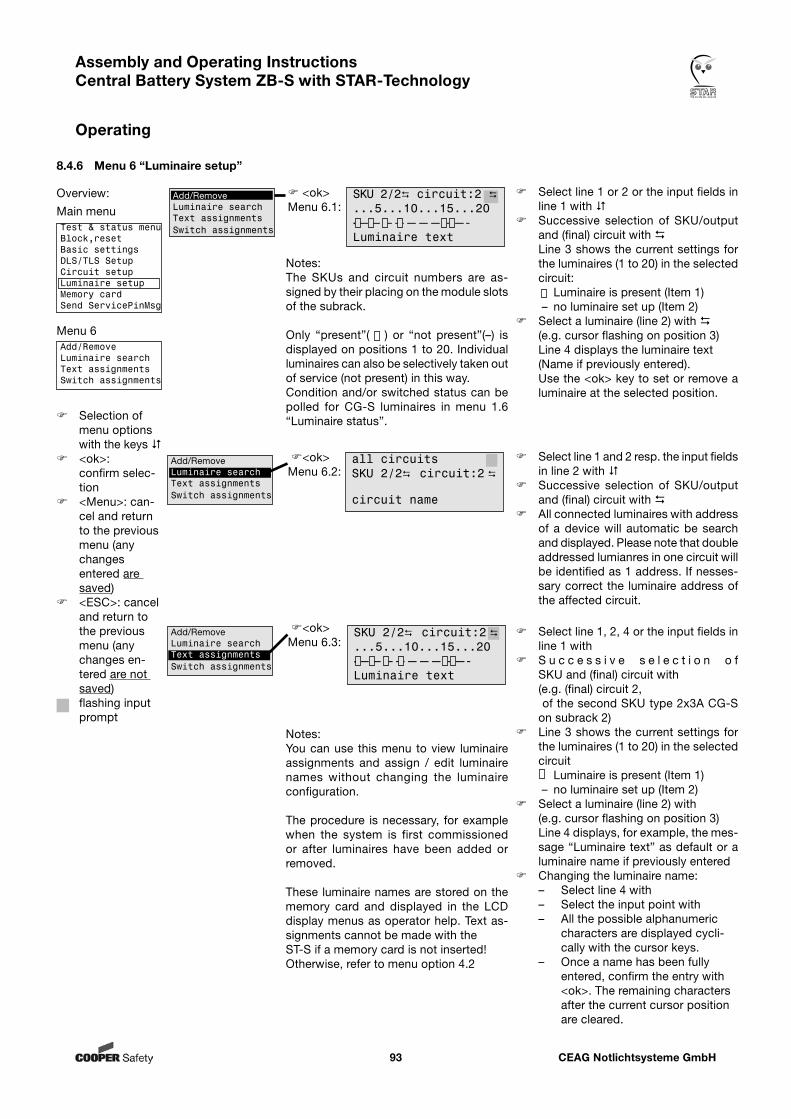
CEAG Notlichtsysteme GmbH93
Assembly and Operating Instructions Central Battery System ZB-S with STAR-Technology
Operating
8.4.6 Menu 6 “Luminaire setup”
Select line 1, 2, 4 or the input fields in line 1 with
S u c c e s s i v e s e l e c t i o n o f SKU and (final) circuit with (e.g. (final) circuit 2,
of the second SKU type 2x3A CG-S on subrack 2)
Line 3 shows the current settings for the luminaires (1 to 20) in the selected circuit
Luminaire is present (Item 1) – no luminaire set up (Item 2) Select a luminaire (line 2) with (e.g. cursor flashing on position 3) Line 4 displays, for example, the mes-
sage “Luminaire text” as default or a luminaire name if previously entered
Changing the luminaire name:– Select line 4 with– Select the input point with – All the possible alphanumeric
characters are displayed cycli-cally with the cursor keys.
– Once a name has been fully entered, confirm the entry with <ok>. The remaining characters after the current cursor position are cleared.
Notes:You can use this menu to view luminaire assignments and assign / edit luminaire names without changing the luminaire configuration.
The procedure is necessary, for example when the system is first commissioned or after luminaires have been added or removed.
These luminaire names are stored on the memory card and displayed in the LCD display menus as operator help. Text as-signments cannot be made with the ST-S if a memory card is not inserted!Otherwise, refer to menu option 4.2
Overview:
Main menuTest & status menuBlock,resetBasic settingsDLS/TLS SetupCircuit setupLuminaire setupMemory cardSend ServicePinMsg
Menu 6Add/RemoveLuminaire searchText assignmentsSwitch assignments
Selection of menu options with the keys
<ok>: confirm selec-tion
<Menu>: can-cel and return to the previous menu (any changes entered are saved)
<ESC>: cancel and return to the previous menu (any changes en-tered are not saved)
flashing input prompt
<ok> Menu 6.1:
SKU 2/2 circuit:2 ...5...10...15...20-—————————-Luminaire text
<ok> Menu 6.3:
SKU 2/2 circuit:2 ...5...10...15...20-—————————-Luminaire text
Add/RemoveLuminaire searchText assignmentsSwitch assignments
Notes:The SKUs and circuit numbers are as-signed by their placing on the module slots of the subrack.
Only “present”( ) or “not present”(–) is displayed on positions 1 to 20. Individual luminaires can also be selectively taken out of service (not present) in this way.Condition and/or switched status can be polled for CG-S luminaires in menu 1.6 “Luminaire status”.
Select line 1 or 2 or the input fields in line 1 with
Successive selection of SKU/output and (final) circuit with
Line 3 shows the current settings for the luminaires (1 to 20) in the selected circuit:
Luminaire is present (Item 1) – no luminaire set up (Item 2) Select a luminaire (line 2) with (e.g. cursor flashing on position 3) Line 4 displays the luminaire text (Name if previously entered). Use the <ok> key to set or remove a
luminaire at the selected position.
Add/RemoveLuminaire searchText assignmentsSwitch assignments
<ok> Menu 6.2:
all circuitsSKU 2/2 circuit:2
circuit name
Add/RemoveLuminaire searchText assignmentsSwitch assignments
Select line 1 and 2 resp. the input fields in line 2 with
Successive selection of SKU/output and (final) circuit with
All connected luminaires with address of a device will automatic be search and displayed. Please note that double addressed lumianres in one circuit will be identified as 1 address. If nesses-sary correct the luminaire address of the affected circuit.
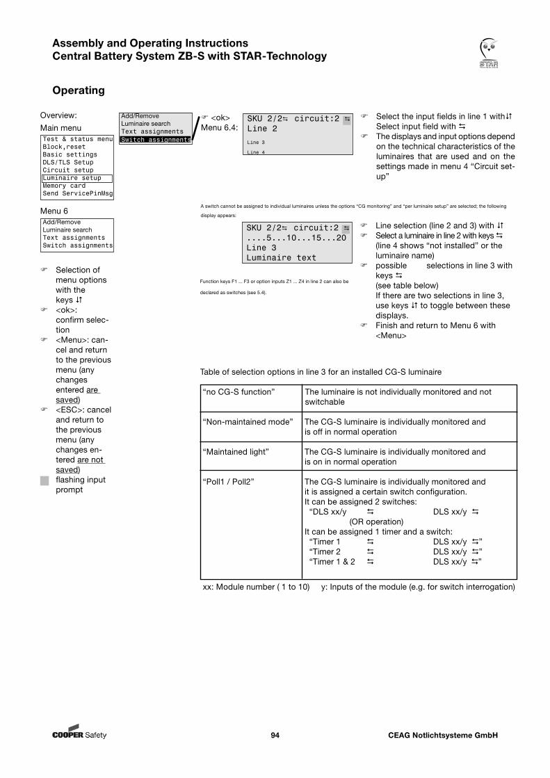
CEAG Notlichtsysteme GmbH94
Assembly and Operating Instructions Central Battery System ZB-S with STAR-Technology
Operating
Line selection (line 2 and 3) with Select a luminaire in line 2 with keys
(line 4 shows “not installed” or the luminaire name)
possible selections in line 3 with keys
(see table below) If there are two selections in line 3,
use keys to toggle between these displays.
Finish and return to Menu 6 with <Menu>
<ok> Menu 6.4:
SKU 2/2 circuit:2 Line 2
Line 3
Line 4
Select the input fields in line 1 with Select input field with The displays and input options depend
on the technical characteristics of the luminaires that are used and on the settings made in menu 4 “Circuit set-up”
A switch cannot be assigned to individual luminaires unless the options “CG monitoring” and “per luminaire setup” are selected; the following
display appears:
Add/RemoveLuminaire searchText assignmentsSwitch assignments
Function keys F1 ... F3 or option inputs Z1 ... Z4 in line 2 can also be
declared as switches (see 5.4).
Overview:
Main menuTest & status menuBlock,resetBasic settingsDLS/TLS SetupCircuit setupLuminaire setupMemory cardSend ServicePinMsg
Menu 6Add/RemoveLuminaire searchText assignmentsSwitch assignments
Selection of menu options with the keys
<ok>: confirm selec-tion
<Menu>: can-cel and return to the previous menu (any changes entered are saved)
<ESC>: cancel and return to the previous menu (any changes en-tered are not saved)
flashing input prompt
Table of selection options in line 3 for an installed CG-S luminaire
“no CG-S function” The luminaire is not individually monitored and not switchable
“Non-maintained mode” The CG-S luminaire is individually monitored and is off in normal operation
“Maintained light” The CG-S luminaire is individually monitored and is on in normal operation
“Poll1 / Poll2” The CG-S luminaire is individually monitored and it is assigned a certain switch configuration. It can be assigned 2 switches: “DLS xx/y DLS xx/y (OR operation) It can be assigned 1 timer and a switch: “Timer 1 DLS xx/y ” “Timer 2 DLS xx/y ” “Timer 1 & 2 DLS xx/y ”
xx: Module number ( 1 to 10) y: Inputs of the module (e.g. for switch interrogation)
SKU 2/2 circuit:2 ....5...10...15...20Line 3Luminaire text
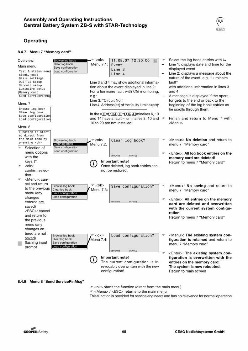
CEAG Notlichtsysteme GmbH95
Assembly and Operating Instructions Central Battery System ZB-S with STAR-Technology
Operating
8.4.7 Menu 7 “Memory card”
<ok> Menu 7.1:
Select the log book entries with – Line 1: displays date and time for the
displayed event– Line 2: displays a message about the
nature of the event, e.g. “Luminaire fault” with additional information in lines 3 and 4
– A message is displayed if the opera-tor gets to the end or back to the beginning of the log book entries as he scrolls through them.
Finish and return to Menu 7 with <Menu>
<ok> Menu 7.2:
Clear log book?
Menu=No OK=YES
<Menu>: No deletion and return to menu 7 “Memory card”
<Enter>: All log book entries on the memory card are deleted!
Return to menu 7 “Memory card”
<ok> Menu 7.3:
Save configuration?
Menu=No OK=YES
<Menu>: No saving and return to menu 7 “Memory card”
<Enter>: All entries on the memory card are deleted and overwritten with the current system configu-ration!
Return to menu 7 “Memory card”
<ok> Menu 7.4:
Load configuration?
Menu=No OK=YES
<Menu>: The existing system con-figuration is retained and return to menu 7 “Memory card”
<Enter>: The existing system con-figuration is overwritten with the entries on the memory card!
The system is now rebooted. Return to main screen
8.4.8 Menu 8 “Send ServicePinMsg” <ok> starts the function (direct from the main menu) <Menu> / <ESC> returns to the main menuThis function is provided for service engineers and has no relevance for normal operation.
Overview:
Main menuTest & status menuBlock,resetBasic settingsDLS/TLS SetupCircuit setupLuminaire setupMemory cardSend ServicePinMsg
Menu 7Browse log bookClear log bookSave configurationLoad configuration
Menu 8Function is start-ed direct from the main menu by pressing <ok>
Selection of menu options with the keys
<ok>: confirm selec-tion
<Menu>: can-cel and return to the previous menu (any changes entered are saved)
<ESC>: cancel and return to the previous menu (any changes en-tered are not saved)
flashing input prompt
Browse log bookClear log bookSave configurationLoad configuration
Browse log bookClear log bookSave configurationLoad configuration
Browse log bookClear log bookSave configurationLoad configuration
Important note!Once deleted, log book entries can-not be restored.
Important note!The current configuration is ir-revocably overwritten with the new configuration!
Browse log bookClear log bookSave configurationLoad configuration
11.08.07 12:30:00 EventLine 3Line 4
Line 3 and 4 may show additional informa-tion about the event displayed in line 2:For a luminaire fault with CG monitoring, e.g.:Line 3: “Circuit No.”Line 4: Address(es) of the faulty luminaire(s): ————————————————————In the example illustrated, luminaires 6, 13 and 14 have a fault – luminaires 3, 10 and 16 to 20 are not installed.
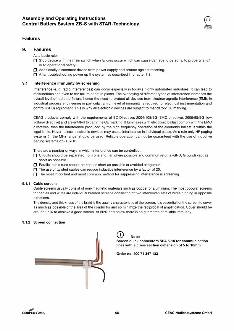
CEAG Notlichtsysteme GmbH96
Assembly and Operating Instructions Central Battery System ZB-S with STAR-Technology
9. Failures As a basic rule: Stop device with the main switch when failures occur which can cause damage to persons, to property and/ or to operational safety. Additionally disconnect device from power supply and protect against resetting. After troubleshooting power up the system as described in chapter 7.8.
9.1 Interference immunity by screeningInterference (e. g. radio interferences) can occur especially in today´s highly automated industries. It can lead to malfunctions and even to the failure of entire plants. The overlaying of different types of interference increases the overall level of radiated failure, hence the need to protect all devices from electromagnetic interference (EMI). In industrial process engineering in particular, a high level of immunity is required for electrical instrumentation and control (I & C) equipment. This is why all electronic devices are subject to mandatory CE marking.
CEAG products comply with the requirements of EC Directives 2004/108/EG (EMC directive), 2006/95/EG (low voltage directive) and are entitled to carry the CE marking. If luminaires with electronic ballast comply with the EMC directives, then the interference produced by the high frequency operation of the electronic ballast is within the legal limits. Nevertheless, electronic devices may cause interference in individual cases. As a rule only HF paging systems (in the MHz range) should be used. Reliable operation cannot be guaranteed with the use of inductive paging systems (25-40kHz).
There are a number of ways in which interference can be controlled. Circuits should be separated from one another where possible and common returns (GND, Ground) kept as short as possible. Parallel cable runs should be kept as short as possible or avoided altogether. The use of twisted cables can reduce inductive interference by a factor of 20. The most important and most common method for suppressing interference is screening.
9.1.1 Cable screensCable screens usually consist of non-magnetic materials such as copper or aluminium. The most popular screens for cables and wires are individual braided screens consisting of two interwoven sets of wires running in opposite directions.The density and thickness of the braid is the quality characteristic of the screen. It is essential for the screen to cover as much as possible of the area of the conductor and so minimize the reciprocal of amplification. Cover should be around 95% to achieve a good screen. At 60% and below there is no guarantee of reliable immunity.
9.1.2 Screen connection
Note: Screen quick connectors SSA 5-10 for communication lines with a cross section dimension of 5 to 10mm.
Order no. 400 71 347 133
Failures
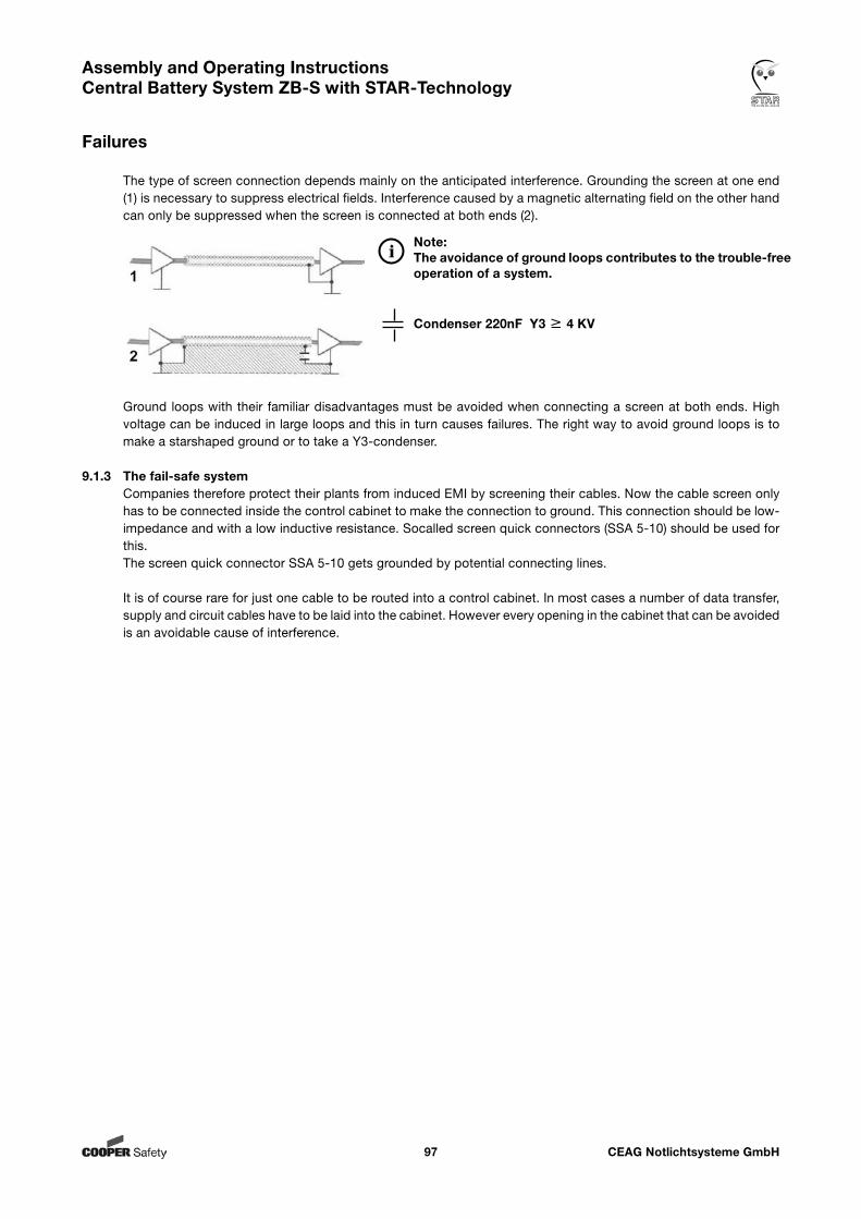
CEAG Notlichtsysteme GmbH97
Assembly and Operating Instructions Central Battery System ZB-S with STAR-Technology
The type of screen connection depends mainly on the anticipated interference. Grounding the screen at one end (1) is necessary to suppress electrical fields. Interference caused by a magnetic alternating field on the other hand can only be suppressed when the screen is connected at both ends (2).
Ground loops with their familiar disadvantages must be avoided when connecting a screen at both ends. High voltage can be induced in large loops and this in turn causes failures. The right way to avoid ground loops is to make a starshaped ground or to take a Y3-condenser.
9.1.3 The fail-safe systemCompanies therefore protect their plants from induced EMI by screening their cables. Now the cable screen only has to be connected inside the control cabinet to make the connection to ground. This connection should be low-impedance and with a low inductive resistance. Socalled screen quick connectors (SSA 5-10) should be used for this. The screen quick connector SSA 5-10 gets grounded by potential connecting lines.
It is of course rare for just one cable to be routed into a control cabinet. In most cases a number of data transfer, supply and circuit cables have to be laid into the cabinet. However every opening in the cabinet that can be avoided is an avoidable cause of interference.
Note: The avoidance of ground loops contributes to the trouble-free operation of a system.
Condenser 220nF Y3 4 KV
Failures
CEAG Notlichtsysteme GmbH98
Assembly and Operating Instructions Central Battery System ZB-S with STAR-Technology
10. Maintenance / Checking
10.1 Safety Notes
WARNING! Risk of Injury!Improper maintenance work can cause serious personal injury and / or material damage. This work has to be performed only by authorised, skilled and adequate personnel who have received instructions providing information on the device and in observance of local safety regulations. Before working on and with the system switch it off and protect it against reset. Do not touch the system unti its temperature is as high as the ambient temperature.
10.2 General information to maintenance / checkingThe carrying out of the safety inspections as required by statutes and directives has to be made regularly. The operator of the emergency lighting system is responsible for organising and supervising this work!The following information must be specified in writing and made available at all times : The nature and extent of the work Recording of work results Responsibilities and permits for carrying out the work - which persons may carry out which operations? - which persons are responsible for supervising the work? Duties of reporting (e. g. in the case of faults or function tests) Organisational measures when working on the emergency lighting system. This may include: - Duties of information and reporting on the start, duration and end of the work - Safety measures while the work is being carried out: e. g. standby lighting, power supply isolation and lock-out (e. g. removing the fuses, key-operated switch, safety signage) - Safety equipment for the personnel carrying out the work on the plant (e. g. suitable work clothing and personal protection equipment) - Safety equipment providing protection from hazards caused by adjacent plant (e. g. safety grilles, barri - ers, making safe or roads)
Maintenance and repair work at the emergency lighting system can be done by the customer service of CEAG Notlichtsysteme GmbH at any time. (s. enclosed Customer Service Order).Our customer service locations can be found all over Germany, see the enclosed map „Addresses: CEAG Customer Service“.
In addition, we offer you a Maintenance Contract for Emergency Lighting making organisation easier to you!This contract contains the annual checking and includes the following work:
- Mains/-battery shift-function of devices - Visual check of electrical equipment and batteries of devices - Mechanical check at the devices - Checking of charging rate - Measurement of battery voltage at load commencement and measurement of the cell voltage - Operational test of other electronics - Checking of lamps only for luminaires with CG-monitoring - Checking of rated operation time (test of capacity) of the batteries
Not included in maintenance services is repair and overhaul work, in particular the replacement of defective electronics or defective light sources.
In case of returns you need a RMA - number from us. For further information see www.ceag.de!
Maintenance / Checking

CEAG Notlichtsysteme GmbH99
Assembly and Operating Instructions Central Battery System ZB-S with STAR-Technology
10.3 Enabling of end circuits with maintenance workBlock the system via the control unit (figure). (menu item 8.4.2)
Before commencing maintenance work in the end circuit this must be separated on all poles.There are several possibilities for separating the end circuit on all poles: disconnect the green plug (figure) on the module, or remove the end circuit fuses on the module and open the neutral conductor disconnection terminal at the output terminal
After maintenance work is finished, reverse the steps and cancel blocking at the control unit.
Overview:
Main menuTest & status menuBlock,resetBasic settingsDLS/TLS SetupCircuit setupLuminaire setupMemory cardSend ServicePinMsg
Menu 2Block deviceRelease deviceManual resetDeep discharge resetISO failure resetISO failure search
Selection of menu options with the keys
<ok>:
<ok>Menu 2.1:
Block deviceRelease deviceManual resetDeep discharge reset
This deviceall devicesDevice address 01 Device address CEAG ZB-S 1
Block deviceRelease deviceManual resetDeep discharge reset
<ok> initiates the function:The selected stations will be swichted free and restart operation.
Selection with the buttons bet-ween the displayed options.Selection of a ZB-S system with
Device address referes to search results in the substation setup menu 3 «Basic settings»
<ok>Menu 2.2:
This deviceall devicesDevice address 01 Device address CEAG ZB-S 1
<ok> initiates the function:All functions are cancelled; all outputs will be isolated! In case of mains failure occures no battery operation (see e.g. 8.3 «All-pole switching off the system» or 8.5 «Battery supply connect/disconnect»)!
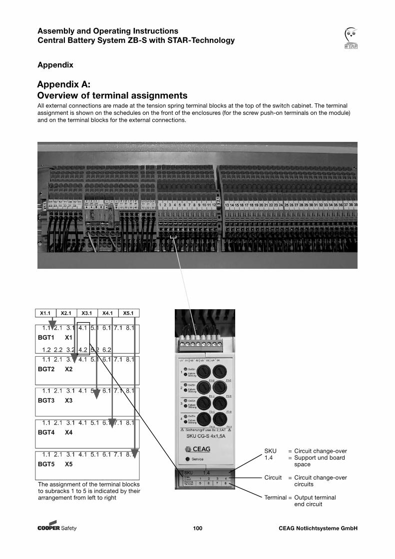
CEAG Notlichtsysteme GmbH100
Assembly and Operating Instructions Central Battery System ZB-S with STAR-Technology
Appendix
Appendix A: Overview of terminal assignmentsAll external connections are made at the tension spring terminal blocks at the top of the switch cabinet. The terminal assignment is shown on the schedules on the front of the enclosures (for the screw push-on terminals on the module) and on the terminal blocks for the external connections.
Terminal designation chartThe assignment of the terminal blocks to subracks 1 to 5 is indicated by their arrangement from left to right
SKU = Circuit change-over1.4 = Support und board space
Circuit = Circuit change-over circuits
Terminal = Output terminal end circuit
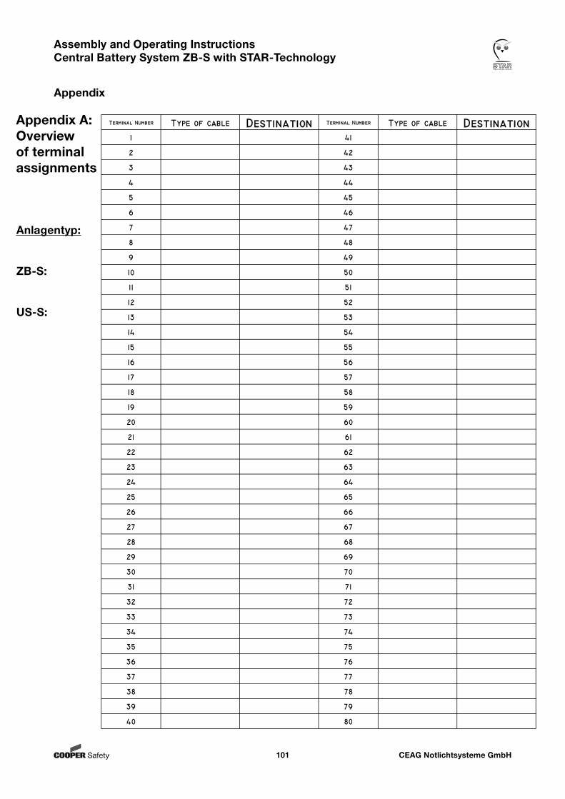
CEAG Notlichtsysteme GmbH101
Assembly and Operating Instructions Central Battery System ZB-S with STAR-Technology
Appendix
Appendix A: Overview of terminal assignments
Anlagentyp:
ZB-S:
US-S:
40
39
38
37
36
35
34
33
32
31
30
29
28
27
26
25
24
23
22
21
20
19
18
17
16
15
14
13
12
11
10
9
8
7
6
5
4
3
2
1
Terminal Number Type of cable Destination
80
79
78
77
76
75
74
73
72
71
70
69
68
67
66
65
64
63
62
61
60
59
58
57
56
55
54
53
52
51
50
49
48
47
46
45
44
43
42
41
Terminal Number Type of cable Destination
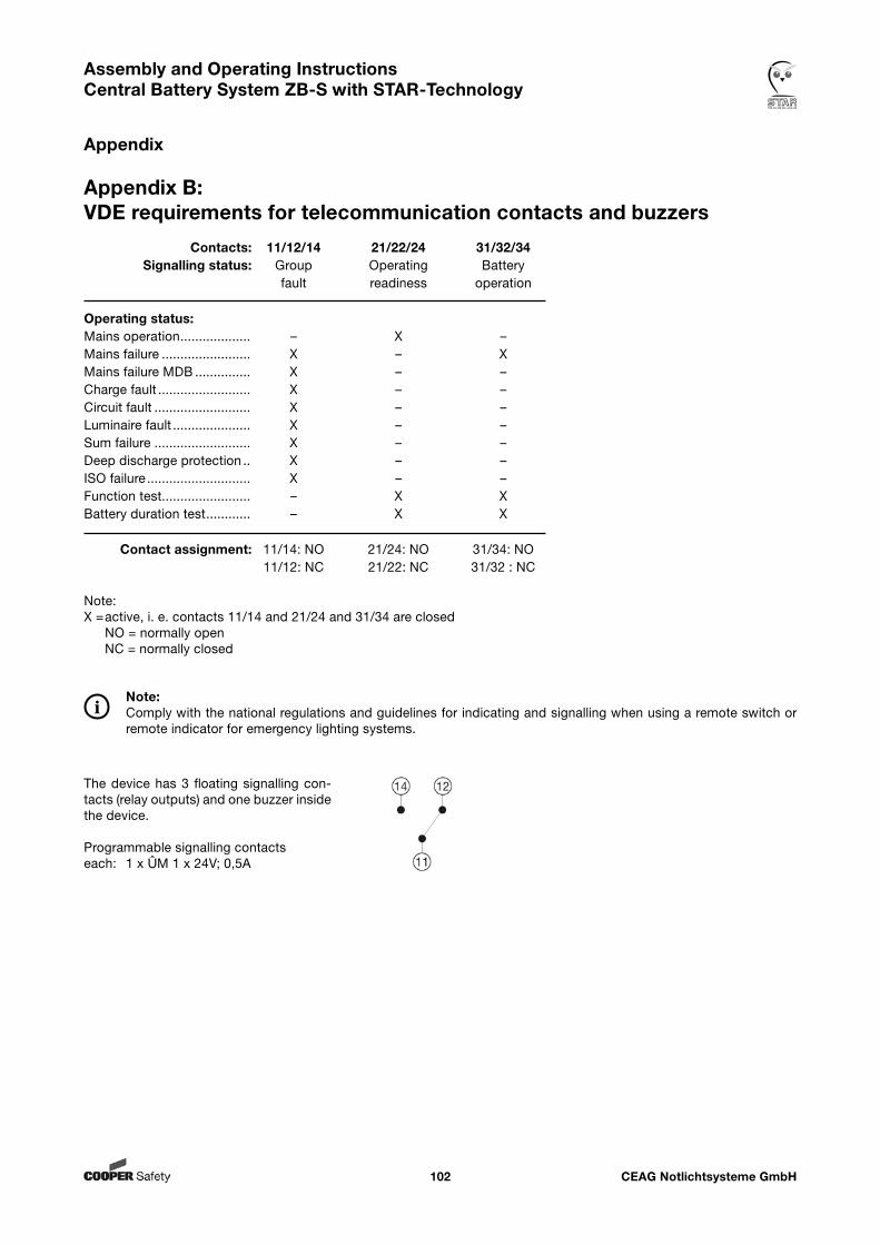
CEAG Notlichtsysteme GmbH102
Assembly and Operating Instructions Central Battery System ZB-S with STAR-Technology
Appendix
Appendix B: VDE requirements for telecommunication contacts and buzzers
The device has 3 floating signalling con-tacts (relay outputs) and one buzzer inside the device.
Programmable signalling contactseach: 1 x ÛM 1 x 24V; 0,5A
Contacts: 11/12/14 21/22/24 31/32/34 Signalling status: Group Operating Battery fault readiness operation
Operating status:Mains operation ................... – X –Mains failure ........................ X – XMains failure MDB ............... X – –Charge fault ......................... X – –Circuit fault .......................... X – –Luminaire fault ..................... X – –Sum failure .......................... X – –Deep discharge protection .. X – –ISO failure ............................ X – –Function test........................ – X XBattery duration test ............ – X X
Contact assignment: 11/14: NO 21/24: NO 31/34: NO 11/12: NC 21/22: NC 31/32 : NC
Note:X = active, i. e. contacts 11/14 and 21/24 and 31/34 are closed NO = normally open NC = normally closed
Note:Comply with the national regulations and guidelines for indicating and signalling when using a remote switch or remote indicator for emergency lighting systems.
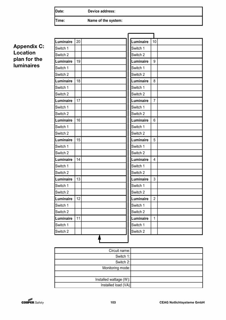
CEAG Notlichtsysteme GmbH103
Assembly and Operating Instructions Central Battery System ZB-S with STAR-Technology
Appendix
Appendix C: Location plan for the luminaires
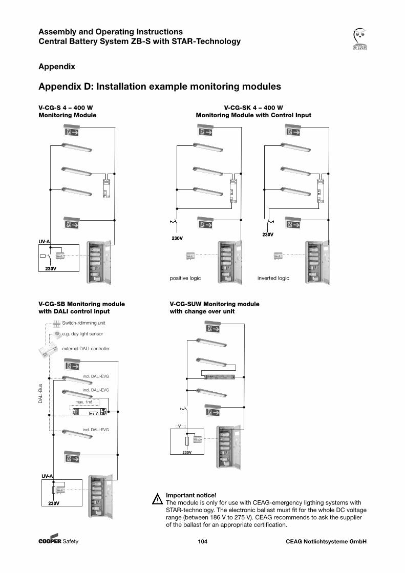
CEAG Notlichtsysteme GmbH104
Assembly and Operating Instructions Central Battery System ZB-S with STAR-Technology
Appendix
Appendix D: Installation example monitoring modules
V-CG-SB Monitoring module with DALI control input
UV-A
Switch-/dimming unit
e.g. day light sensor
external DALI-controller
DA
LI-B
us
incl. DALI-EVG
incl. DALI-EVG
incl. DALI-EVG
max. 1m!
V-CG-SUW Monitoring module with change over unit
230V
V
UV-A
V-CG-S 4 – 400 W Monitoring Module
V-CG-SK 4 – 400 W Monitoring Module with Control Input
Important notice! The module is only for use with CEAG-emergency ligthing systems with STAR-technology. The electronic ballast must fit for the whole DC voltage range (between 186 V to 275 V). CEAG recommends to ask the supplier of the ballast for an appropriate certification.
positive logic inverted logic
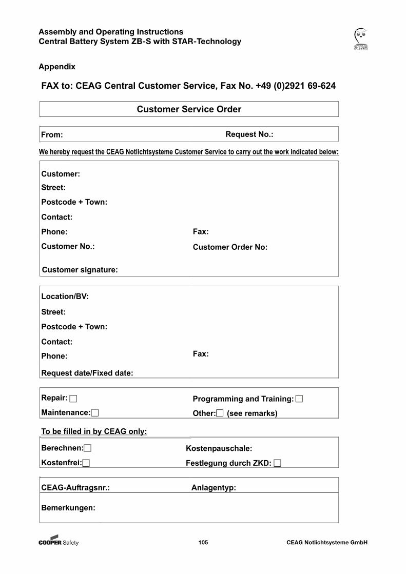
CEAG Notlichtsysteme GmbH105
Assembly and Operating Instructions Central Battery System ZB-S with STAR-Technology
Appendix
CEAG Notlichtsysteme GmbH106
Assembly and Operating Instructions Central Battery System ZB-S with STAR-Technology
Appendix

CEAG Notlichtsysteme GmbH107
Assembly and Operating Instructions Central Battery System ZB-S with STAR-Technology
Appendix
300 80 001 457 (K)/XXX/08.11/WK