Embed Size (px)
Citation preview
CoolMOS™ SJ MOSFETs benefitsin hard and soft switching SMPS topologieswww.infineon.com/coolmos
Single
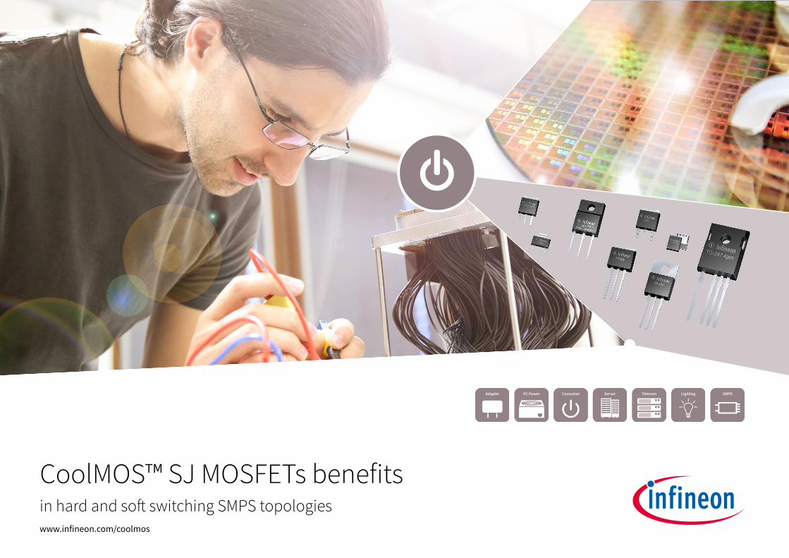
Hard switching topologies So� switching topologies
SMPS switching topologies
CoolMOS™ series
DCM CCM Full-bridgeHalf-bridge Full-bridge
PFCTwo transistor
forward(TTF/ITTF)
Flyback/quasi-resonant
flyback
Smart meter
PC Silver box 80 +
E�iciency = CoolMOS™ C7Price/performance = 600 V, 700 V, 800 V and 950 V CoolMOS™ P7
CoolMOS™ C6/E6/CE/P6
E�iciency = 600 V CoolMOS™ C7 Price/performance = CoolMOS™ P7
CoolMOS™ C6/E6/CE/P6CoolMOS™ CFD2/CFD7
PC Silver box PFC
Adapter/LED lighting LED street lighting
PC Silver box 90 +
Server/telecom Server/telecom
Adapter
EV charging EV charging
UPC
LLC ZVS phase-shi�
PFC PWM PWM
Applications
Charger
LCD TV
Hard and soft switching topologies, applications and suitable CoolMOS™ families
CoolMOS™ benefits
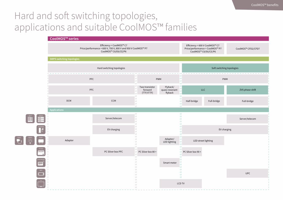
Hard switching: Quasi-resonant flyback circuit
Hard switching: Power factor correction circuit
Soft switching: LLC half-bridge
Soft switching: ZVS phase-shift full-bridge
Examples of hard and soft switching topologies
CoolMOS™ benefits
Vin
CoolMOS™ CoolMOS™
CoolMOS™ CoolMOS™
SiC Diode
CoolMOS™
ICE2PCSxx
CoolMOS™
Controller
CoolMOS™
CoolMOS™
ICE1HSO1G
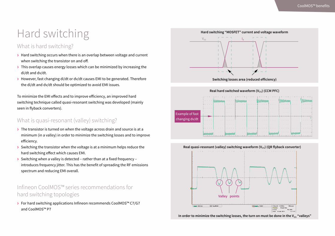
Hard switchingWhat is hard switching? › Hard switching occurs when there is an overlap between voltage and current
when switching the transistor on and off.
› This overlap causes energy losses which can be minimized by increasing the di/dt and dv/dt.
› However, fast changing di/dt or dv/dt causes EMI to be generated. Therefore the di/dt and dv/dt should be optimized to avoid EMI issues.
To minimize the EMI effects and to improve efficiency, an improved hard switching technique called quasi-resonant switching was developed (mainly seen in flyback converters).
What is quasi-resonant (valley) switching? › The transistor is turned on when the voltage across drain and source is at a
minimum (in a valley) in order to minimize the switching losses and to improve efficiency.
› Switching the transistor when the voltage is at a minimum helps reduce the hard switching effect which causes EMI.
› Switching when a valley is detected – rather than at a fixed frequency –introduces frequency jitter. This has the benefit of spreading the RF emissions spectrum and reducing EMI overall.
Infineon CoolMOS™ series recommendations for hard switching topologies › For hard switching applications Infineon recommends CoolMOS™ C7/G7
and CoolMOS™ P7
Hard switching “MOSFET” current and voltage waveform
Switching losses area (reduced efficiency)
Real quasi-resonant (valley) switching waveform (VDS) (QR flyback converter)
In order to minimize the switching losses, the turn on must be done in the VDS “valleys”
Valley points
Real hard switched waveform (VDS) (CCM PFC)
Example of fastchanging dv/dt
VDS Id
CoolMOS™ benefits
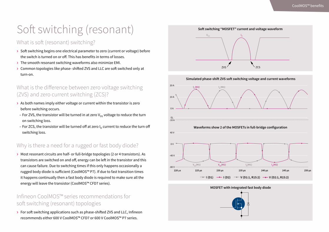
Soft switching (resonant)What is soft (resonant) switching? › Soft switching begins one electrical parameter to zero (current or voltage) before
the switch is turned on or off. This has benefits in terms of losses.
› The smooth resonant switching waveforms also minimize EMI.
› Common topologies like phase- shifted ZVS and LLC are soft switched only at turn-on.
What is the difference between zero voltage switching (ZVS) and zero current switching (ZCS)? › As both names imply either voltage or current within the transistor is zero
before switching occurs. – For ZVS, the transistor will be turned in at zero VDS voltage to reduce the turn on switching loss.
– For ZCS, the transistor will be turned off at zero ID current to reduce the turn off switching loss.
Why is there a need for a rugged or fast body diode? › Most resonant circuits are half- or full-bridge topologies (2 or 4 transistors). As
transistors are switched on and off, energy can be left in the transistor and this can cause failure. Due to switching times if this only happens occasionally a rugged body diode is sufficient (CoolMOS™ P7). If due to fast transition times it happens continually then a fast body diode is required to make sure all the energy will leave the transistor (CoolMOS™ CFD7 series).
Infineon CoolMOS™ series recommendations for soft switching (resonant) topologies › For soft switching applications such as phase-shifted ZVS and LLC, Infineon
recommends either 600 V CoolMOS™ CFD7 or 600 V CoolMOS™ P7 series.
Soft switching “MOSFET” current and voltage waveform
MOSFET with integrated fast body diode
VDS(M1) VDS(M2) lD(M1) lD(M2)
220 µs 225 µs 230 µs 235 µs 240 µs 245 µs 250 µs
20 A
10 A
0 A
EL-10 A
40 V
0 V
-40 V
-80 V
lD (M2) lD (M1)
I (D1) I (D2) V (D1:1, R15:2) V (D2:1, R15:2)
Simulated phase-shift ZVS soft switching voltage and current waveforms
VDS ID
ZVS ZCS
Waveforms show 2 of the MOSFETs in full-bridge configuration
CoolMOS™ benefits
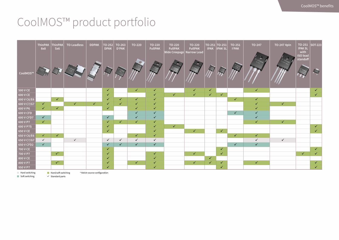
CoolMOS™ product portfolio
Hard/soft switchingStandard parts
* Kelvin source configurationHard switchingSoft switching
ThinPAK 8x8
ThinPAK 5x6
TO-Leadless DDPAK TO-252 DPAK
TO-263 D2PAK
TO-220 TO-220 FullPAK
TO-220 FullPAK
Wide Creepage
TO-220 FullPAK
Narrow Lead
TO-251 IPAK
TO-251 IPAK SL
TO-251 I2PAK
TO-247 TO-247 4pin TO-251 IPAK SL
with ISO lead standoff
SOT-223
CoolMOS™
500 V CE 600 V CE 600 V C6/E6 600 V C7/G7 600 V P6 600 V CFD 600 V CFD7 600 V P7 600 V P7S 650 V CE 650 V C6/E6 650 V C7/G7 650 V CFD2 700 V CE 700 V P7 * 800 V CE 800 V P7 * 950 V P7
CoolMOS™ benefits

Hard switching 650 V CoolMOS™ C7/G7: NEW! Fastest switching series, best suited for high efficiency at hard switching topologies.
Hard/soft switching CoolMOS™ E6: CoolMOS™ C3 replacement series optimized for DCM applications in PFC and PWM. Improved low load efficiency over CoolMOS™ C3. CoolMOS™ C6: CoolMOS™ C3 replacement series. Improved low load efficiency, also with improved “rugged” diode for use in cost sensitive soft switching topologies as well as hard switching. CoolMOS™ P6: Price/performance series, suitable for hard and soft switching. 600 V CoolMOS™ C7/G7: NEW! Fastest switching series, suitable for hard switching topologies and soft switching.CoolMOS™ CE: Right fit for consumer applications with competitive cost, fast delivery and high quality for use in hard and soft switching topologies. 600 V CoolMOS™ P7: Replacement for P6, price/ performance series, suitability for wide range of applications in hard and soft switching topologies700 V/800 V/950 V CoolMOS™ P7: Replacement for CE/C3, designed and optimized for flyback topologies
Soft switching CoolMOS™ CFD: Original fast body diode series suitable for hard commutation resonant soft switching topologies.CoolMOS™ CFD2: CoolMOS™ CFD replacement series. Improved low load efficiency and improved fast body diode control enabling lower EMI and overshoot voltage. Suitable for hard commutation resonant soft switching topologies.CoolMOS™ CFD7: NEW! Replacement of CoolMOS™ CFD2 for new designs, improved efficiency and BIC robustness; suitable for hard commutation resonant soft switching topologies
For more information on individual CoolMOS™ parts in the above different series, please go to www.infineon.com/coolmos
CoolMOS™ benefits
Published byInfineon Technologies Austria AG9500 Villach, Austria
© 2018 Infineon Technologies AG.All Rights Reserved.
Order Number: B152-H9621-V4-7600-EU-EC-PDate: 09 / 2018
Please note!THIS DOCUMENT IS FOR INFORMATION PURPOSES ONLY AND ANY INFORMATION GIVEN HEREIN SHALL IN NO EVENT BE REGARDED AS A WARRANTY, GUARANTEE OR DESCRIPTION OF ANY FUNCTIONALITY, CONDITIONS AND/OR QUALITY OF OUR PRODUCTS OR ANY SUITABILITY FOR A PARTICULAR PURPOSE. WITH REGARD TO THE TECHNICAL SPECIFICATIONS OF OUR PRODUCTS, WE KINDLY ASK YOU TO REFER TO THE RELEVANT PRODUCT DATA SHEETS PROVIDED BY US. OUR CUSTOMERS AND THEIR TECHNICAL DEPARTMENTS ARE REQUIRED TO EVALUATE THE SUITABILITY OF OUR PRODUCTS FOR THE INTENDED APPLICATION.
WE RESERVE THE RIGHT TO CHANGE THIS DOCUMENT AND/OR THE INFORMATION GIVEN HEREIN AT ANY TIME.
Additional informationFor further information on technologies, our products, the application of our products, delivery terms and conditions and/or prices, please contact your nearest Infineon Technologies office (www.infineon.com).
WarningsDue to technical requirements, our products may contain dangerous substances. For information on the types in question, please contact your nearest Infineon Technologies office.
Except as otherwise explicitly approved by us in a written document signed by authorized represen-tatives of Infineon Technologies, our products may not be used in any life-endangering applications, including but not limited to medical, nuclear, military, life-critical or any other applications where a failure of the product or any consequences of the use thereof can result in personal injury.
Service hotline
Infineon offers its toll-free 0800/4001 service hotline as one central number, available 24/7 in English, Mandarin and German.
› Germany .................... 0800 951 951 951 (German/English)
› China, mainland ....... 4001 200 951 (Mandarin/English)
› India .......................... 000 800 4402 951 (English)
› USA ............................ 1-866 951 9519 (English/German)
› Other countries ......... 00* 800 951 951 951 (English/German)
› Direct access ............. +49 89 234-0 (interconnection fee, German/English)
* Please note: Some countries may require you to dial a code other than “00” to access this international number. Please visit www.infineon.com/service for your country!
Where to buy
Infineon distribution partners and sales offices: www.infineon.com/wheretobuy
Mobile product catalog
Mobile app for iOS and Android.