Embed Size (px)
Citation preview

PDHonline Course M320 (7 PDH)
Cooling Towers - Made Easy
2012
Instructor: A. Bhatia, B.E.
PDH Online | PDH Center5272 Meadow Estates Drive
Fairfax, VA 22030-6658Phone & Fax: 703-988-0088
www.PDHonline.orgwww.PDHcenter.com
An Approved Continuing Education Provider

www.PDHcenter.com PDH Course M320 www.PDHonline.org
Cooling Towers – Made Easy A. Bhatia, B.E.
CONTENTS
Overview
Section 1 – Evaporative Cooling Towers
Section 2 – Cooling Tower Performance
Section 3 – Cooling Tower Types
Section 4 – Cooling Tower Capacities & Availability
Section 5 – Cooling Tower Materials
Section 6 – Components of a Cooling Tower
Section 7 – Sizing Your Tower
Section 8 – Cooling Tower Capacity Controls
Section 9 – Layout Considerations (recirculation and starvation
Section 10 – Installation Considerations
Section 11 – Fans, Drives and Motors
Section 12 – Water Distribution Pumps (flow and head estimation)
Section 13 – Noise and Vibration
Section 14 – Cooling Tower Water Balance
Section 15 – Cooling Water Treatment
Section 16 – Cooling Tower Operation in Freezing Weather
Section 17 - Cooling Tower Testing
Section 17- Codes and Guides
Section 18 – Example
© A. Bhatia Page 1 of 61
Glossary

www.PDHcenter.com PDH Course M320 www.PDHonline.org
COOLING TOWERS – MADE EASY
Overview
Most industrial production processes need cooling water to operate efficiently and safely. Refineries,
steel mills, petrochemical manufacturing plants, electric utilities and paper mills all rely heavily on
equipment or processes that require efficient temperature control. Cooling water systems control these
temperatures by transferring heat from hot process fluids into cooling water. As this happens, the
cooling water itself gets hot; before it can be used again it must either be cooled or replaced by a fresh
supply of cool water.
A Cooling Tower is a heat rejection device that extracts waste heat to the atmosphere by cooling a
stream of hot water in the tower. This type of heat rejection is termed "evaporative" because it allows a
small portion of the water being cooled to evaporate into a moving air stream and thereby provides
significant cooling to the rest of that water stream. The heat that is transferred from the water stream to
the air stream raises the air's temperature and its relative humidity to 100%, and this air is discharged
to the atmosphere.
Types of Cooling Processes
Two basic types of water cooling processes are commonly used. One transfers the heat from warmer
water to cooler air mainly by an evaporation heat-transfer process and is known as the evaporative or
wet cooling. These are also termed as open systems. The other transfers the heat from warmer water
to cooler air by a sensible heat-transfer process and is known as the non-evaporative or dry cooling.
These are also termed as closed cooling water systems because the water does not come in contact
with outside air.
Dry cooling towers operate by heat transmission through a surface that divides the working fluid from
ambient air. These rely mainly on convection heat transfer to reject heat from the working fluid, rather
than evaporation. The cooling takes place through air-cooled exchangers similar to radiators.
The advantages of these systems include:
© A. Bhatia Page 2 of 61
1. Precise temperature control, which is critical in many process applications

www.PDHcenter.com PDH Course M320 www.PDHonline.org
2. The water loss is negligible as the water remains in a closed loop. This system consumes very little
water for make up and thus water treatment costs will be less. This system is recommended where
water is scarce.
3. Ability to operate at very high temperatures (200ºF) and under sub-freezing conditions using
ethylene glycol, alcohol or brines.
Other variant of closed cooling system is the once through system. Here the cooling water is drawn
from estuary, lake or river; used in process once and is disposed back to the source. There is no re-
circulation.
Once-through cooling is usually employed when the cooling water demands are high and water is
readily available in abundance. Environmental regulation of hot water discharge or concerns of aquatic
life go against using this system. Local environment authority having jurisdiction must permit such
installation.
Evaporative systems is a recirculation water system that accomplishes cooling by providing intimate
mixing of water and air, which results in cooling primarily by evaporation. A small portion of the water
being cooled is allowed to evaporate into a moving air stream to provide significant cooling to the rest of
that water stream.
Water is re-circulated and reused again and again. The water evaporation is approximately 1% of the
flow for each 10ºF drop in temperature. The heat from the water stream transferred to the air stream
raises the air's temperature and its relative humidity to 100%, and this air is discharged to the
atmosphere.
In general, the most applications rely on the use of evaporative cooling tower systems, which include
wet cooling towers, cooling ponds or spray ponds.
The course covers 18 sections of comprehensive information on evaporative cooling towers and
provides important aspects of cooling tower types, sizing, selection and performance issues. Let’s first
define few important terms for understanding this course. A detailed glossary is provided at the end of
the course.
Cooling Tower Terms and Definitions
© A. Bhatia Page 3 of 61
Some useful terms, commonly used in the cooling tower industry:

www.PDHcenter.com PDH Course M320 www.PDHonline.org
1. BTU (British thermal unit) - BTU is the heat energy required to raise the temperature of one
pound of water one degree Fahrenheit in the range from 32° F to 212° F.
2. Cooling Range - The difference in temperature between the hot water entering the tower and the
cold water leaving the tower is the cooling range.
3. Approach - The difference between the temperature of the cold water leaving the tower and the
wet- bulb temperature of the air is known as the approach. Establishment of the approach fixes the
operating temperature of the tower and is a most important parameter in determining both tower
size and cost.
4. Drift - Water droplets that are carried out of the cooling tower with the exhaust air. Drift loss does
not include water lost by evaporation. Proper tower design can minimize drift loss. The drift rate is
typically reduced by employing baffle-like devices, called drift eliminators, through which the air
must travel after leaving the fill and spray zones of the tower.
5. Heat Load - The amount of heat to be removed from the circulating water within the tower. Heat
load is equal to water circulation rate (gpm) times the cooling range times 500 and is expressed in
BTU/hr. Heat load is also an important parameter in determining tower size and cost.
6. Ton - An evaporative cooling ton is 15,000 BTU's per hour. The refrigeration ton is 12000 BTU’s per
hour.
7. Wet Bulb Temperature (WBT) - The lowest temperature that water theoretically can reach by
evaporation. Wet-Bulb temperature is an extremely important parameter in tower selection and
design and should be measured by a psychrometer.
8. Dry-Bulb Temperature - The temperature of the entering or ambient air adjacent to the cooling
tower as measured with a dry-bulb thermometer.
9. Pumping Head - The pressure required to pump the water from the tower basin, through the entire
system and return to the top of the tower
© A. Bhatia Page 4 of 61
10. Makeup - The amount of water required to replace normal losses caused by bleed off, drift, and
evaporation.

www.PDHcenter.com PDH Course M320 www.PDHonline.org
11. Bleed off - The portion of the circulating water flow that is removed in order to maintain the amount
of dissolved solids and other impurities at an acceptable level. As a result of evaporation, dissolved
solids concentration will continually increase unless reduced by bleed off
SECTION 1 – EVAPORATIVE COOLING TOWERS
An evaporative cooling tower is a heat exchanger that transfers heat from circulating water to the
atmosphere. Warm water from the heat source is pumped to the top of the tower and will than flow
down through plastic or wooden shells. As it falls downward across baffles, the water is broken into
small droplets. Simultaneously, air is drawn in through the air inlet louvers at the base of the tower and
travels upward through the wet deck fill opposite the water flow. A small portion of the water is
evaporated which removes the heat from the remaining water causing it to cool down 10 to 20˚C. The
water falls down into a basin and will be brought back into the production process from there. Some of
the water is lost to evaporation and thus the fresh water is constantly added to cooling tower basin to
make up the difference.
Cooling Tower Principle
Evaporation results in cooling…
On a warm day when you work or play hard, your body heats up, and you begin to sweat. Because
your skin is more moist than the air, the sweat EVAPORATES and it ABSORBS heat from your body.
By absorbing heat from your body, the temperature of your body is lowered. It is the evaporation or the
change from a liquid to a vapor of the water on your skin which causes the skin to be cooled. If you
stand in a breeze, you feel cooler, even though the temperature of the breeze will be the same as the
temperature of still air. The breeze STEPS UP the EVAPORATION process of the sweat and more
rapidly cools the body. It is not the breeze alone that makes you feel cooler. It is the increase in the rate
of evaporation which makes the body feels cooler.
© A. Bhatia Page 5 of 61
All cooling towers operate on the principle of removing heat from water by evaporating a small portion
of the water that is recirculated through the unit. The heat that is removed is called the latent heat of
vaporization. Each one pound of water that is evaporated removes approximately 1,050BTU's in the
form of latent heat. The amount of heat lost by the water depends on the temperature rise of the
ambient air before it leaves the tower. This means that both the dry bulb and wet bulb temperatures of
the air are important. When WBT = DBT, this condition corresponds to 100% relative humidity (RH) that

www.PDHcenter.com PDH Course M320 www.PDHonline.org
implies the air is fully saturated. The air will no longer accept water and the lack of evaporation do not
allow the wetted bulb to reject heat into the air by evaporation.
Higher the difference between DBT and WBT, lower is the relative humidity or drier is the air. The lower
relative humidity indicates greater capacity of air to absorb or hold water and shall result in efficient
lowering of water temperatures.
Sensible Cooling…
The air temperature rises as it absorbs sensible heat from the water. This sensible heat transfer occurs,
if the dry bulb temperature (DBT) of air is less than the DBT of water. This may account for 20% of the
cooling.
Why Evaporative Cooling
The advantages of evaporative cooling stem from several key factors. First, evaporative cooling
process use the ambient wet-bulb temperature of the entering air as the heat sink, which is typically
10°F to 30°F lower than the dry bulb, depending on the local climate. The lower the temperature of the
heat sink, the more efficient will be the process.
Second, the evaporative cooling process involves both latent and sensible heat transfer (primarily
latent) where a small portion of the recirculating flow is evaporated to cool the remaining water. For
every pound of water evaporated into the airstream, approximately 1,050 Btu of heat is rejected. In
contrast, a pound of air at standard conditions has a heat content of only 0.24 Btu/1b-°F, meaning that
much greater air volume is required to reject the same heat load in air cooled (sensible only) cooling
systems as compared to evaporative cooled systems.
Third, due to water's ability to efficiently transport large quantities of heat over relatively long distances,
water-cooled systems allow the economical separation of the process equipment and heat rejection
equipment.
© A. Bhatia Page 6 of 61
Fourth, evaporative cooling towers allow direct contact between the water and the air, which is a highly
efficient process. This mixing occurs in the fill, sometimes called the wet deck, which is typically
comprised of sheets of thermoformed plastic. The fill provides a large amount of low-cost surface area
for air and water to contact each other.

www.PDHcenter.com PDH Course M320 www.PDHonline.org
These reasons combine to explain why evaporative cooling towers are smaller and require much less
fan energy than air-cooled equipment.
Summarizing:
Both the evaporative and sensible heat transfer occurs as the warmer water comes in contact with the
cooler air.
1. Total heat transferred = Heat of evaporation + Sensible Heat
2. Every pound of water evaporated into the airstream allows the air to carry away approximately
1,050 Btu of energy from the process to be cooled. This value varies slightly with climate.
3. Higher the difference between DBT and WBT, lower is the relative humidity (or drier is the air) and
more effective will be the cooling tower performance. A cooling tower should be installed in places
where there is considerable differential between dry bulb temperature and wet bulb temperature.
SECTION 2 – COOLING TOWER PERFORMANCE
Cooling tower performance depends on four factors (1) Range; (2) Heat load; (3) Ambient wet-bulb
temperature or relative humidity and (4) Approach.
Range
Range is the temperature difference between the hot water inlet and cold water outlet at the tower. For
instance a design demanding, the hot water coming @ 100ºF and required to be cooled to 90ºF is said
to have a range of 10ºF.
Increasing the range will reduce the capital cost and energy cost of the tower.
Heat Load
Heat load of cooling water is indicated by standard heat transfer equation:
Q = m Cp ∆T
© A. Bhatia Page 7 of 61
Where

www.PDHcenter.com PDH Course M320 www.PDHonline.org
Q is heat load in Btu/hr
m is cooling water mass in lbs/hr
Cp is specific heat of water = 1 Btu/lb-°F
∆T is the inlet/outlet temperature differential in ºF
The above equation can be simplified in volumetric flow rates as
Q (in Btu/hr) = 8.33 lbs/Gallons x 60 hr/min x 1 x ∆T (ºF)
Heat Load (Btu/hr) = 500 x flow in GPM x Range in °F
Wet-bulb Temperature (WBT)
The Wet bulb temperature (WBT) is a site condition measured by placing a thin film of water on the
bulb of a thermometer. A non-wetted thermometer reading provides ‘dry bulb’ temperature (DBT)
reading. A comparison of wet and dry bulb readings allows the relative humidity to be determined from
a psychometric chart or the air properties table. The wet bulb temperature is always lower than the dry
bulb value except when the air is fully saturated with water – a condition known as 100% relative
humidity. This is when the wet and dry bulb temperatures are the same.
A tower cannot cool the hot process water to a temperature any lower than the wet bulb temperature of
the entering air.
The wet bulb temperature is also the dew point of the ambient air. It is not possible or practical to
design a cooling tower that can provide cooling water equal to or lower than prevailing wet bulb
temperature of the air. Each tower system must be specifically sized for each geographic area’s
prevailing summer wet bulb temperature. High efficiency mechanical draft towers cool the water to
within 5 or 6°F of the wet-bulb temperature, while natural draft towers cool within 10 to 12°F.
© A. Bhatia Page 8 of 61
In general, it is assumed that the ambient air wet bulb temperature, usually obtained from ASHRAE
climatic design information (Tables 1B, 2B, and 3B of the 2001 Fundamentals Handbook, Chapter 26)
represents the entering air wet bulb temperature. In fact, this is only true if the tower is located away
from any heat sources that may elevate the local temperature. The Cooling Technology Institute, CTI,
defines the ambient wet bulb temperature as that measured between 50 and 100 feet upwind of the
tower, with no interfering heat sources between the point of measurement and the tower, and at an

www.PDHcenter.com PDH Course M320 www.PDHonline.org
elevation of 5 feet above the tower base. Very few cooling tower installations fit this description.
Therefore, for cooling tower selection, the entering wet bulb temperature, which is usually 1 or 2ºF
higher than the ambient wet-bulb is specified to account for any potential recirculation.
Approach
How closely the leaving cold water temperature approaches the entering air wet bulb temperature,
simply termed as the approach. Approach is the temperature difference between the cold water leaving
the tower and ambient wet bulb temperature. If a cooling tower produces 85°F cold water when the
ambient wet bulb is 78°F, then the cooling tower approach is 7°F.
Approach is the most important indicator of cooling tower performance. It dictates the theoretical limit to
the leaving cold-water temperature and no matter the size of the cooling tower, range or heat load: it is
not possible to cool the water below the wet bulb temperature of air.
It should be noted that when the WBT falls, the leaving water temperature from the cooling tower also
decreases. This is a linear relationship when flow and range are constant.
The approach temperatures generally fall between 5 and 20ºF implying that the leaving CWT shall be 5
to 20ºF above the ambient WBT no matter is quantum of heat load or the size of the cooling tower. As
the selected approach is reduced, tower size increases exponentially. Neither it is economical to select
a cooling tower for approaches less than 5ºF nor do any manufacturer guarantees the performance for
approaches less than 5ºF.
Effectiveness of Cooling Tower
For a given type of cooling tower, a closer (smaller) approach temperature indicates a more effective
tower. Selecting a cooling tower with a close approach will supply the cooler water … but the capital
cost and energy consumption of the tower will be higher, too. Note that effectiveness refers to the
thermal efficiency of the cooling tower fill and the evaporative process; do not confuse this with the
mechanical efficiency of the cooling tower. The mechanical efficiency refers to the fan power that’s
required to circulate ambient air over the cooling tower fill. Different types of cooling towers differ in
their mechanical efficiencies.
A fact to note…
© A. Bhatia Page 9 of 61
Does cooling tower dictate rate of heat transfer? …. NO it doesn’t.

www.PDHcenter.com PDH Course M320 www.PDHonline.org
A cooling tower simply gives up the heat it is given. The cooling of water is proportional to the
difference in enthalpies of the leaving and entering air streams. The heat given by the water falling
inside the tower equals the heat gained by the air rising through the tower.
A big size cooling tower may accomplish the cooling of say 1000 GPM of water flow from 90 to 80 °F. If
it is ‘small’, it might cool the 1000 GPM water from 100 to 90 °F. In either case, the heat transfer and
evaporation rates are the same. The size of the cooling tower, the flow rate and the wet bulb
temperature determine the inlet and outlet water temperatures- but not the difference between them.
Summarizing:
Range = Hot water inlet temperature (HWT) – Cold water outlet temperature (CWT)
Approach = Cold water outlet temperature (CWT) – WBT
With constant flow, when the heat load decreases, the range decreases. This is expressed by Heat
load (Q) = 500 x water flow (GPM) x range (°F)
SECTION 3 - COOLING TOWER TYPES
Cooling towers are designed and manufactured in several types, with numerous sizes available in each
type. With respect to drawing air through the tower, there are two types of cooling towers: (1) Natural
draft and (2) Mechanical draft.
Natural Draft Cooling Towers
Natural-draft cooling towers use the buoyancy of the exhaust air rising in a tall chimney to provide the
draft. Warm, moist air naturally rises due to the density differential to the dry, cooler outside air. Counter
intuitively, more moist air is less dense than drier air at the same temperature and pressure. This moist
air buoyancy produces a current of air through the tower. Note the characteristics of natural draft towers
below:
© A. Bhatia Page 10 of 61
1. Natural draft cooling towers rely on stack effect that allows the air movement on density differential.
Many early designs just rely on prevailing winds to generate the draft of air.

www.PDHcenter.com PDH Course M320 www.PDHonline.org
2. Natural draft cooling towers are characterized by distinct shape much like a tall cylinder with a tight
belt around the waist to provide stability
3. Such towers have the advantage of not requiring any fans, motors, gearboxes, etc. The tall stack
insures against re-circulation of air
Although relatively inexpensive, they are usually applied only in very small sizes, and are fare more
affected by adverse wind conditions. Their use on processes requiring accurate, dependable cold water
temperatures is not recommended.
Another natural type of cooling tower also known as hyperbolic natural draft tower is quite dependable
and predictable in its thermal performance. Typically, these towers tend to be quite large (250,000 gpm
and greater) and occasionally in excess of 500 feet in height. These are used extensively in the field of
electric power generation.
Mechanical Draft Cooling Towers
Mechanical draft cooling towers use either single or multiple fans to force or draw air through the
circulating water. Their thermal performance is less affected by psychrometric variables and thus tends
towards greater stability than the natural draft towers.
These can be categorized as forced draft (air pushing) or induced draft (draw-thru) arrangement by
virtue of the location of fan.
Forced draft
In forced draft cooling towers, air is "pushed" through the tower from an inlet to an exhaust. A forced
draft mechanical draft tower is a blow-through arrangement, where a blower type fan at the intake
forces air through the tower. These are characterized by high air entrance velocities and low exit
velocities.
The forced draft cooling towers have certain disadvantages:
© A. Bhatia Page 11 of 61
1. The blower forces outside air into the tower creating high entering and low exiting air velocities. The
low exiting velocity of warm moisture laden air has the tendency to get re-sucked by the blower fan.
This increases the apparent wet bulb temperature, and the cooling tower ceases to give the desired
approach.

www.PDHcenter.com PDH Course M320 www.PDHonline.org
2. A Forced draft Cooling Tower can only be square or rectangular shaped. Forced draft arrangement
always has a fan on the side. Due to this the cooling tower cannot be bottle shaped. Further, due to
this characteristic, the water distribution system cannot be that of a sprinkler form. This results in
inefficient water distribution.
3. It is difficult to maintain this type of a cooling tower because of the inaccessibility of the fills. Cold
water basin is covered and difficult to access.
4. Pressurized upper casing is more susceptible to water leaks than the induced draft styles.
5. A forced draft design typically requires more motor horsepower typically double that of a
comparable induced draft counter-flow cooling tower.
6. With the fan on the air intake, the fan is more susceptible to sever icing with resultant imbalance
when moving air laden with either natural or recirculated moisture.
Usually forced draft towers are equipped with centrifugal blower type fans which although require more
horsepower than propeller type fans, have the advantage of being able to operate against high static
pressures. Therefore they can be installed indoors in more confined spaces or within a specifically
designed enclosure that provides significant separation between intake and discharge locations to
minimize recirculation.
© A. Bhatia Page 12 of 61
Induced draft

www.PDHcenter.com PDH Course M320 www.PDHonline.org
An induced draft mechanical draft tower is a draw-through arrangement, where a fan located at the
discharge end pulls air through tower. The fan induces hot moist air out the discharge. This produces
low entering and high exiting air velocities, reducing the possibility of recirculation in which discharged
air flows back into the air intake. When compared to forced draft cooling towers, induced draft towers
have following advantages:
1. Recirculation tendency is less a problem. The air that is thrown out from the top of the Cooling
Tower has no chance of getting back into the Cooling Tower. The push of the fan adds to the
upward thrust of the warm air.
2. The induced draught can be square as well as round. The distribution system is that of a sprinkler
which is considered to be the most efficient water distribution system.
3. Noise level is very low, because the fan and motor are placed on the top of the Cooling Tower.
They are not in level with the observer
4. A forced draft Cooling Tower cannot be a Cross-flow type model. An induced draught can be either
Cross-flow or Counter-flow.
5. The parts of this type of cooling tower are easily accessible and there is no problem in their
maintenance.
Types of Induced Draft Tower
Induced draft cooling towers are characterized as Cross-flow and Counter-flow designs, by virtue of air-
to-water flow arrangement. The difference lies in the FILL arrangement.
© A. Bhatia Page 13 of 61
Counter-flow Cooling Towers

www.PDHcenter.com PDH Course M320 www.PDHonline.org
In a counter-flow induced draft cooling towers, air travels vertically across the fill sheet, opposite to the
downward motion of the water. Air enters an open area beneath the fill media and is then drawn up
vertically. The water is sprayed through pressurized nozzles and flows downward through the fill,
opposite to the air flow.
Cross-flow Cooling Towers
© A. Bhatia Page 14 of 61
In Cross-flow induced draft cooling towers, air enters one or more vertical faces of the cooling tower
and moves horizontally through the fill material. Water drops by gravity and the air pass through the
water flow into an open plenum area. A shallow pan type elevated basin is used to distribute hot water
over the tower fill by means of orifices in the basin floor. The application obviates the need for a
pressure-spray distribution system and relies on gravity distribution.

www.PDHcenter.com PDH Course M320 www.PDHonline.org
Crossflow towers are also sub-classified by the number of fill banks and air inlets that are served by
each fan. The tower indicated in schematic above is a double-flow tower because the fan is inducing air
through two inlets and across two banks of fill.
The surface enclosing the top structure of an induced draft cooling tower, exclusive of the distribution
basins on a crossflow tower is called Fan deck.
Comparative Analysis (Counter-flow v/s Cross-flow)
What is Common to both designs?
1. Both are generally induced flow arrangement although counter-flow design is available in forced
flow arrangement too.
2. The interaction of the air and water flow allows a partial equalization and evaporation of water.
3. Both are generally draw-thru arrangement where a fan induces hot moist air out the discharge.
4. Both produces low entering and high exiting air velocities, reducing the possibility of recirculation.
What is Different in Cross-flow and Counter-flow designs?
© A. Bhatia Page 15 of 61
The comparative analysis is made on the following distinctive parameters.

www.PDHcenter.com PDH Course M320 www.PDHonline.org
1. Fill Media
Counter-flow cooling towers utilize a plastic film fill heat exchange media that reduces both pump
head and horsepower costs; cross-flow towers typically utilize a splash-type heat exchanger.
However, it is possible to find either type of exchange media in both types of towers.
2. Space and Size Constraints
Counter-flow tower is compact and have smaller footprint, but these tend to be taller than Cross-
flow models, require more pump head and utilize more fan power than their cross-flow counterparts.
The physically higher size also demands taller architectural screens. Cross-flow cooling towers
have larger foot print area because of the cavity which is to be left between the fan and the fills.
3. Dimensional references
For cross-flow towers, length is always perpendicular to the direction of air flow through the fill (air
travel), or from casing to casing. For counter-flow towers, length is always parallel to the long
dimension of a multi-cell tower, and parallel to the intended direction of cellular extension on single-
cell towers
4. Spray Pattern (Water Distribution)
Counter-flow towers use pressurized spray systems that is considered to be the most efficient
method of water distribution in a cooling tower. No sprinkler distribution is possible in a cross-flow
cooling tower.
5. Operating Weight
Counter-flow towers have low operating weight and thus find greater acceptability at roof
locations. Cross-flow operating weight is higher than the counter-flow tower.
6. Fill Arrangement
© A. Bhatia Page 16 of 61
For counter-flow tower, the wet deck (fill media) is encased on all the four sides. This helps prevent
icing in winter operation. The prevailing winds do not directly affect the fill. Entire working system is
guarded from the sun's rays and helps reduce algae growth. Air inlet louvers serve as screens to
prevent debris from entering system. Cross-flow wet deck (fill) is encased on two sides only. The
prevailing winds directly affect the fill and have problems of icing in winter operation. A cross-flow

www.PDHcenter.com PDH Course M320 www.PDHonline.org
cooling tower where two opposed fill banks are served by a common air plenum is termed double
flow arrangement.
7. Fill Support
In counter-flow design, the wet deck (fill) is supported from structural supports underneath. This
prevents sagging and creates a working platform on top of the fill for service. In cross-flow design,
the fill media is generally supported by rods. Icing and wear may deteriorate the fill making it sag,
which may affect performance.
8. Operating Efficiency
Counter-flow cooling towers are 25% more efficient than cross-flow type. The reason being that as
the air is being sucked from the lower part of the cooling tower, it rises upwards, gets warmer and
when it reaches the top, it is hottest at that point. Since the water is flowing in the downward, it is
the hottest at the top. Thus hottest of air meets the hottest of water and evaporation is more and
thus the cooling is more.
In this case a cross-flow tower, air that passes the water, is not capable to pass waters at different
temperatures. Thus the level of cooling in this case is less.
9. Operation in Freeze Climates
Counter-flow tower’s configuration tends to confine ice formation to areas of greatest structural
strength, however, it is also the most difficult to de-ice. This is because their straight sided shape
reduces the opportunity for direct warm water contact with a major ice formation, requiring more
frequent fan reversal. Cross-flow towers have an inwardly sloping air inlet face which assures
continuous contact of warm water with critical areas and with only occasional fan reversal,
promotes rapid de-icing.
10. Safety Requirements
Counter-flow towers are typically taller than other styles but do not require handrails or piping at top
of tower. Cross-flow towers many a times require handrail, safety cage, & service platform per the
requirements of OSHA guidelines. It is difficult to service fan drive system in cross-flow towers and
these must have internal & external service platforms and ladders to reach drive systems.
© A. Bhatia Page 17 of 61
11. Maintenance

www.PDHcenter.com PDH Course M320 www.PDHonline.org
Counter-flow towers are easy to maintain at cold-water basin level because this is open on all sides
with no restrictions from wet deck. Cross-flow tower are difficult to clean at the cold water basin
under wet deck because of limited access.
12. Balancing Requirements
Counter-flow does not need balancing valves to even the flow. For cross-flow, open gravity hot
water basins require balancing valves to insure even flow and maximum performance.
13. Limitations
Counter- flow tower require airflow on all four sides for optimum performance. Care must be taken
not to lay out more than (2) towers side by side or middle cells will be difficult to access, outer cells
may have to be shut down to service inner cells.
14. Initial Cost
Counter-flow towers are typically expensive to build and have higher initial cost v/s. Cross-flow
tower.
SECTION 4 - COOLING TOWER CAPACITIES & AVAILABILITY
Mechanical draft towers are available in a large range of capacities. The nominal capacities range from
approximately 15 gallons per minute (GPM) to several thousand GPM. Based on the capacity sizes, the
towers can be either factory built or field erected.
Packaged Cooling Towers
Packaged towers are the one where the first or essentially all assembly is done at the point of
manufacture, whereupon they are shipped to the site in as few sections as the mode of transportation
will permit. Towers of this type usually are mass produced in factories with FRP or galvanized steel
structure and casing.
© A. Bhatia Page 18 of 61
Package towers are typically used in air-conditioning and small industrial cooling applications requiring
flow rates below 10000 GPM. Large office buildings, hospitals, schools typically use one or multiple
cooling towers as part of their air conditioning systems.

www.PDHcenter.com PDH Course M320 www.PDHonline.org
Cooling Towers for HVAC duty are usually described by their tons of cooling capacity. The cooling
capacity indicates the rate at which the cooling tower can transfer heat. One ton of cooling is equal to
12,000 BTUs (British thermal units) per hour, or 200 BTUs per minute. The heat rejected from an air
conditioning system equals about 1.25 times the net refrigeration effect. Therefore the equivalent ton on
the cooling tower side actually rejects about 15,000 Btu/hour (12000 Btu cooling load plus 3000 Btu’s
per ton for work of compression). Cooling tower capacities at commercial, industrial, or institutional
facilities typically range from as little as 50 tons to as much as 1,000 tons or more. Large facilities may
be equipped with several large cooling towers.
Where water is scarce, HVAC chillers can be air-cooled. However, water-cooled chillers are normally
more energy efficient than air-cooled chillers due to heat rejection to tower water at near wet-bulb
temperatures. Air-cooled chillers reject heat near to the dry-bulb temperature, and thus have lower
average effectiveness.
Note that, a cooling tower is an auxiliary cooling device – it doesn’t cool the building directly – but rather
it helps other air-conditioning (chiller) equipment do that job.
Field Erected Cooling Towers
Field erected towers are those on which the primary construction activity takes place at the site of
ultimate use. These are generally manufactured and/or assembled at jobsite making use of framed
structures. All large towers are prefabricated, piece marked and shipped to the site for final assembly.
Erection supervision for final assembly is usually provided by the cooling tower manufacturer.
The field erected cooling towers are typically specified with very high thermal duties demanding water
flow rates ranging from 10000 to 350000 GPM.
© A. Bhatia Page 19 of 61
The field-erected towers are generally used in most industrial and utility applications such as power
plants, petroleum refineries, petrochemical plants, natural gas processing plants, food processing
plants, semi-conductor plants, and other industrial facilities. To give an example, the circulation rate of
cooling water in a typical 700 MW coal-fired power plant with a cooling tower amounts to about 71,600
cubic meters an hour (315,000 U.S. gallons per minute) and the circulating water requires a supply
water make-up rate of perhaps 5 percent (i.e., 3,600 cubic meters an hour). A typical large refinery
processing 40,000 metric tonnes of crude oil per day (300,000 barrels per day) circulates about 80,000
cubic meters of water per hour through its cooling tower system.

www.PDHcenter.com PDH Course M320 www.PDHonline.org
Many a times, towers are constructed so that they can be ganged together to achieve the desired
capacity. Thus many cooling towers are assemblies of two or more individual cooling towers or cells.
Such cooling towers are referred to by the number of cells they have e.g. a five cell cooling tower.
Multiple cell towers can be linear, square or round depending upon the shape of the individual cells and
whether the air inlets are located on the sides or bottoms of cells.
SECTION 5 - COOLING TOWER MATERIALS
Cooling tower structures are constructed using variety of materials. While package cooling tower are
generally constructed with fiberglass, galvanized steel (or stainless steel in special situations), many
possibilities exist for field-erected structures. Field-erected towers can be constructed of Douglas fir,
redwood, fiberglass, steel or concrete. Each material has advantages and disadvantages.
1. Wood - In early days, towers were constructed primarily of Redwood because of its natural
tendency to inhibit decay. As the Redwood resources diminished, Douglas-Fir come into existence.
Douglas-Fir however supports the growth and proliferation of micro-organisms causing rapid
diglinification (eating of wood). Various methods of pressure treatment and incising are used to
prevent micro-organisms attack to wood, which includes CCA and ACC treatment. Chromate
Copper Arsenate (CCA) was initially used as a preservative but because of its arsenic content, Acid
Copper Chromate (ACC) has replaced it. Irrespective of any treatment, the leaching of chemicals is
still a concern to the environment and sometimes extensive additional water treatment of blowdown
and tower sediment is needed. Some drawbacks of wooden towers are stated below:
• The wooden structure is less durable and the life expectance of is low. Delignification (eating of
wood) is controlled by adjusting pH strictly between 7 and 7.5
• The drift losses are over 1%.
• Tower has a larger footprint and need more space when compared to other alternatives.
• Algae formation is a continuous problem in this type of Cooling Tower.
• The wooden structure is less durable.
© A. Bhatia Page 20 of 61
• Wooden tower usually use large concrete tank that involves more cost, time and labor.

www.PDHcenter.com PDH Course M320 www.PDHonline.org
• Since these towers are extremely heavy, they have to be installed on ground only.
• The nozzles on the wooden tower consume a significant amount of pressure head, which result
in pressure drop.
• Wood can be damaged by excessive levels of free chlorine and is sensitive to prolonged
exposure to excessively hot water. Design hot water temperature should be limited to 140°F or
should be controlled to that level by use of a cold water by-pass.
2. Galvanized Steel – The most cost-effective material of construction for packaged towers is G-235
hot dip galvanized steel, from both structural and corrosion resistance standpoint. G-235 is the
heaviest mill galvanizing commercially available, and offers a substantial amount of protection as
compared to the lighter zinc thicknesses in use several decades ago, providing reliable corrosion
protection for most HVAC and industrial system water chemistries. The most common upgrade from
G-235 galvanized steel is Type 304 stainless steel. Parts that are submerged during operation
and/or at shutdown can benefit the most by upgrading to stainless steel.
*Note that the G-235 designation refers to 2.35 ounces of zinc per square foot (717 g per m2) of the
steel sheet.
3. Stainless Steel - Type 304 stainless steel construction is recommended for cooling towers that are
to be used in a highly corrosive duty.
4. Concrete Towers - Larger field erected towers for power plant and refinery applications are
constructed of concrete. Concrete towers will last more than 40 years, but they are the most
expensive to build. Because of their cost, they represent only 2 to 3% of all field-erected towers.
Sometimes concrete construction is also used for architectural reasons- where the tower is
disguised to look like or blend in with a building- or, the cooling tower is designed as a structure with
a life expectancy equal to the facility it serves.
Circulating water in want of calcium (quantified by a negative Saturation Index) can be corrosive to
concrete components, in which case the concrete gives up a portion of its calcium content in an
effort to “neutralize” the water. Chemical treatment of the circulating water should be aimed at
maintaining a slightly positive Saturation Index.
© A. Bhatia Page 21 of 61
5. Fibre-reinforced Plastic (FRP) Towers - Currently, the fastest growing segment of the cooling
tower market is structures built with pultruded FRP sections. The capability of plastics to be

www.PDHcenter.com PDH Course M320 www.PDHonline.org
moulded into single parts of complex shape and dimensions is a distinct advantage, particularly for
close tolerance components such as fan blades and fan cylinders. This inert inorganic material is
strong, lightweight, chemically resistant and able to handle a range of pH values. Fire-retardant
FRP can eliminate the cost of a fire protection system, which can equal 5 to 12% of the cost of a
cooling tower.
Note that for the cooling towers erected over a concrete basin, height is measured from the elevation of
the basin curb. "Nominal" heights are usually measured to the fan deck elevation, not including the
height of the fan cylinder. Heights for towers on which a wood, steel, or plastic basin is included within
the manufacturer's scope of supply are generally measured from the lowermost point of the basin, and
are usually overall of the tower.
SECTION 6 – COMPONENTS OF A COOLING TOWER
The average life of a cooling tower is estimated at approximately 20 years and well-maintained towers
often can operate well beyond that. Most towers are designed such that air moving components and
heat transfer media can be replaced when necessary, often resulting in higher unit performance as
technological advances occur in the industry. The key to longevity is keeping the base structure of the
tower usable, especially the cold water basin. The important components of the cooling tower are
grouped in three categories 1) structural components, 2) mechanical components and 3) electrical
components.
Structural Components
The structural components of the cooling tower include cold water basin, framework, water distribution
system, fan deck, fan cylinders, mechanical equipment supports, fill, drift eliminators, casing and
louvers.
© A. Bhatia Page 22 of 61
1) Cold Water Basin: The cooling tower basins serves two fundamentally important functions of 1)
collecting the cold water following its transit of the tower and 2) acting as the tower’s primary
foundation. A basin usually has a sump or low point for the cold-water discharge connection. In
most of the designs the cold water basin is beneath the entire fill.
Typical materials for basins include wood, steel, plastic, concrete or coated metals. Plastic basins
generally are limited to small towers for structural reasons, while steel basins can be used on all

www.PDHcenter.com PDH Course M320 www.PDHonline.org
sizes. Steel basins may be of carbon steel (galvanized or painted) or stainless steel, and of either
bolted or welded construction. If bolted, joints must be gasketed and sealed leak tight. Light-weight,
corrosion-resistant fibreglass reinforced polyester (FRP) also is popular for casing panels for
corrosion resistance and lighter weight. Concrete basins for large wood or steel framed field erected
cooling towers are usually designed and built by the purchaser, utilizing the dimensional and load
information provided by the manufacturer.
The basin must be deep enough to provide sufficient hydraulic head for proper water flow into the
sump(s) and to accept the transient water and potential backflow at pump shutdown. Beyond this,
the basin may be made deep enough to hold a reserve in case of interrupted make-up water supply
to stabilize water temperatures under highly variable loads.
As a general rule, the basin should be sized to hold three times the rate of circulation in gallons per
minute.
2) Basin Sumps and Screens: Sumps for towers with wood or steel basins are normally designed
and furnished by manufacturer. Concrete sumps provided by owner, should be designed for water
entrance velocities of less than 3 ft/sec and should be sufficient depth to satisfy pump suction head
requirements. Screens are usually required to prevent debris and should be maximum ½” square
mesh, sized for 1 ft/sec net velocity through the open area of the screen. Screens should be held in
place by channels imbedded in the sump walls to allow for easy removal.
3) Tower Framework: Factory assembled towers predominate in steel construction whereas the most
commonly used material for the framework of field erected towers is wood and concrete with steel
utilized infrequently to conform to a local building code. In large wood towers, the columns are
normally spaced on 4’ x8’ or 6’ x 6’ canters. These bay sizes have evolved over the years of
experience and have proved the best to properly support the fill, drift eliminator and louver modules,
as well as to keep lumber sizes to those that are readily available.
A uniform wind load design of 30 lbs per sq-ft is standard with higher values either dictated or
advisable in some areas. Earthquake loads, if applicable shall be in accordance with zones defined
in Uniform Building Code.
© A. Bhatia Page 23 of 61
4) Packing Materials: Packing materials (splash bars, fills) are used to enhance performance of
cooling tower by providing increased surface area between air and water.

www.PDHcenter.com PDH Course M320 www.PDHonline.org
o Splash Fills- Splash fills breaks up the water and interrupts its vertical progress, by causing it to
cascade through successive offset levels of parallel splash bars. The splashing causes the
water to disperse into droplets thereby increasing the contact of water and air. Treated wood
splash bars is still specified for wood towers, but plastic splash fill promotes better heat transfer
and is now widely used where water quality demands the use of wider spaced splash fill. Splash
fill is characterized by reduced air pressure losses and is not conducive to clogging.
o Film Fills – Film fill causes the water to spread into a thin film, flowing over large vertical areas,
to promote maximum exposure to the air flow. Film fill is typically made of corrugated plastic
sheets that have been joined into blocks that have a honeycombed appearance. Hot water
falling onto the distribution deck forms a surface film as it channels through the fill down to the
cooling tower basin. Plastics are widely used for fill, including, PVC, polypropylene and other
polymers. Film fill offer higher efficiency and is a preferred choice where the circulating water is
generally free of debris. Debris could plug the fill passageways thereby requiring higher
maintenance and cleaning.
5) Hot Water Distribution System: Those parts of a tower beginning with the inlet connection which
distribute the hot circulating water within the tower to the points where it contacts the air for effective
cooling. May include headers, laterals branch arms, nozzles, distribution basins, and flow-regulating
devices. Nozzles are fabricated out of PVC, ABS, polypropylene and glass filled nylon. Water
enters through a removable wave suppressor splash box. A typical supply piping arrangement,
applicable to multi-cell crossflow or counterflow towers positions the supply line adjacent to the long
side of the tower and running the full length. Vertical risers (one per cell) connect the supply line to
the manufacturer’s inlet connections at the elevation of the tower’s distribution system. Valves are
usually installed in these risers to isolate individual cells when needed.
6) Air Inlet Screens: An Air inlet screen is the point of entry for the air entering a tower. The inlet may
take up an entire side of a tower-cross-flow design- or be located low on the side or the bottom of
counter-flow designs. Install coarse mesh screens over the air intake components of the cooling
tower to reduce the ingress of leaves and coarse debris.
© A. Bhatia Page 24 of 61
7) Fan Deck: The fan deck is considered a part of the tower structure acting as a diaphragm for
transmitting dead and live loads to the tower framing. It also provides a platform for the support of
the fan cylinders, as well as an access way to the mechanical equipment and water distribution
system.

www.PDHcenter.com PDH Course M320 www.PDHonline.org
8) Fan Cylinders: The fan cylinder affects the proper flow of air through the tower. The essence of a
well designed fan cylinder incorporates an eased inlet to promote smooth flow of air to the fan,
minimum fan blade tip clearance, a smooth profile below and above the fan, sufficient structural
strength to main a stable plan and profile and sufficient height to prevent recirculation and protect
operating personnel. FRP because of its formability, strength, relatively light weight, stability and
resistance to water and weathering is the preferred material for this application.
9) Louvers: Generally, cross-flow towers have inlet louvers to equalize airflow into the fill and retain
the water within the tower. Many counter-flow tower designs do not require louvers.
10) Drift Eliminators: An assembly of baffles or labyrinth passages through which the air passes prior
to its exit from the tower, for the purpose of removing entrained water droplets from the exhaust air.
The eliminator reduces the drift – to 0.002% -or less- to 0.0005% of the circulating water flow.
Generally the drift eliminators are PVC type, 10 mil minimum sheet thicknesses with 25 mil
minimum PVC stiffeners, UV protected, capable of supporting weight of maintenance workers
without damage to top surface.
11) Casing: A Cooling tower casing acts to contain water within the tower, provide an air plenum for the
fan, and transmit the wind loads to the tower framework. It must have diaphragm strength, be
watertight and corrosion resistant.
12) Ladders & Handrails: Ladders and Handrails for tower access are necessary for large field
erected cooling towers and make sense on some factory assembled designs. A hot dip galvanized
steel access door and ladder is necessary in each cell for internal access to fill from the fan deck
level. These are safety & maintenance accessories that are recommended per the guidelines of
OSHA standards. Seismic Bracing options exist in the in earthquake prone areas.
13) Cooling Tower Bypasses: Bypasses are generally specified for towers installed in cold climates. The
bypass is used to prevent overcooling of the water when there is little or no heat load in the system.
The bypass should discharge into the tower basin as far as possible from the cooling water pump
suctions. This reduces the chance of cavitations due to disturbances in the flow of water to the pump
suctions.
Mechanical Components
© A. Bhatia Page 25 of 61
Mechanical components basic to the operation of the cooling towers are fans, speed reducers, drive
shafts and water flow control valves.

www.PDHcenter.com PDH Course M320 www.PDHonline.org
1) Cooling Tower Fan: Fans provide the airflow for mechanical draft cooling towers. Generally,
propeller fans driven through v-belts are used. These are protected with a belt guard, or with drive
shafts and gear boxes. Depending upon their size, propeller fans can either be fixed or adjustable
variable pitch. A fan having non-automatic adjustable pitch blades permits the same fan to be used
over a wide range of airflows at the lowest power draw. Automatic pitch blades can vary airflow in
response to changing load conditions. Aluminum, FRP and hot dipped galvanized steel are
commonly used fan materials.
2) Speed Reducers: Cooling tower fans are operated at a very low RPM that seldom coincides with
the most efficient speed of the driver (motor). This dictates that a speed reduction and power
transmission unit of some sort be situated between motor and the fan. Speed reduction is generally
accomplished either by differential gears of positive engagement or by differential pulleys (sheaves)
connected through V-belts. Typically, gear reduction units are applied through a wide range of
horse power ratings from the very large down to as little as 5 hp. V-belts are usually applied at
ratings of 50 hp or less.
3) Drive Shaft: The drive shaft transmits power from the output shaft of the motor to the input shaft of
the gear reducer. Because the drive shaft operates within the tower, it must be highly corrosion
resistant (generally stainless steel). It is very important that drive shafts be properly balanced.
Imbalance not only causes tower vibration, but also induces higher loads and excessive wear on
the mechanical equipment couple to the shaft.
4) Valves: Valves are used to control and regulate the flow through the water lines serving the tower.
Valves utilized for cooling tower application include stop valves, flow control valves and make-up
regulator valves. Stop valves are usually the gate or butterfly type. Because flow control valves are
customarily supplied with crossflow towers, stop valves are not normally considered mandatory in
their case.
Electrical Components
© A. Bhatia Page 26 of 61
1) Electric Motors: Electric motors used to drive fan on the mechanical draft cooling towers must be
capable of reliable operation under extremely adverse conditions of high humidity. Two basic types
of motor enclosures are “open” and “totally enclosed”. The open motor circulates external air inside
the enclosure for cooling whereas totally enclosed motor prevents outside air from entering the
enclosure. Open motors are further classified as drip proof, splash proof and weather protected –
the distinction between them being the degree of protection provided against falling or air-borne

www.PDHcenter.com PDH Course M320 www.PDHonline.org
water gaining access to live and rotating parts. Drip proof motor is NOT recommended in cooling
tower applications.
Totally enclosed motors are recommended cooling tower applications as these are more resilient to
fumes, dust, sand, snow and high humidity conditions. These can provide a high quality installation
either in or out of the air stream.
2) Motor Service Factor: The service factor of a motor is indication of its maximum allowable
continuous power output, as compared to its nameplate rating. A 1.0 service factor motor should
not be operated beyond its rated horse power at design ambient conditions, whereas a 1.15 service
factor motor will accept a load 15 percent in excess of its nameplate rating. Use of 1.15 service
factor motor is recommended for cooling tower fan loads at or near nominal horse power ratings.
3) Motor Insulation: Insulation is categorized by classes – A, B, F and H commonly used in USA with
class A carrying the lowest temperature rating and class H the highest. Class B insulation are
designed for a maximum altitude of 3300 feet and a maximum ambient temperature of 40°C. Class
F insulation is used for higher altitudes as well as higher ambient, and is gaining increased use as a
means of improving service factor of a motor of given frame size.
4) Motor Torques: Normal torque motors perform satisfactorily for cooling tower applications and high
starting torque motors are not recommended for cooling tower drives.
5) Motor Controls and Protective Devices: Controllers serves to start and stop the fan motor and to
protect it from overload or power supply failure. In addition various protective devices such as
safety switches, circuit breakers, disconnect switch, manual and magnetic starters, enclosures must
be as per the applicable electrical codes.
SECTION 7 – SIZING YOUR TOWER
Four fundamental factors affect tower size: heat load, range, approach, and ambient wet-bulb
temperature. If three of these factors remain constant, then changing the fourth factor will affect tower
size in the following way:
© A. Bhatia Page 27 of 61
1. Tower size varies directly and linearly with the heat rejection load. If the heat rejection is to be
doubled, the tower size will double.

www.PDHcenter.com PDH Course M320 www.PDHonline.org
2. Tower size varies inversely with range. For a given heat rejection duty, higher range will reduce the
circulating water flow rate. Lower water flow rate in turn will demand lower surface area for heat
transfer and reduce the size of the cooling tower. Lower circulating flow rate will also reduce the
pumping horsepower. However, this is offset by increases in the size of heat exchange equipment
in the plant due to lower LMTD's. Detailed life cycle economics need to be performed to select an
optimal range. It is not economical to select range higher than 20ºF.
3. Tower size varies inversely with approach. As the selected approach is reduced, tower size
increases exponentially. It is not economical to select the cooling tower approaches below 5º F.
4. Tower size varies inversely with wet-bulb temperature. The effect of wet-bulb temperature is similar
to approach. At constant heat load, range and approach, the tower size varies inversely with the actual
wet-bulb temperature. In essence, it would take a tower of infinite size to cool the water to the wet-bulb
temperature. The reason for this is that most of the heat transfer occurs by evaporation and the air's
ability to absorb moisture reduces with temperature. When sizing a cooling tower, the highest
anticipated wet bulb should be used.”
What parameters are needed for tower selection?
As a minimum, four parameters 1) the heat load from the process, 2) water inlet temperature, 3) water
outlet temperature and 4) ambient wet bulb temperatures must be known. For instance the recirculation
water flow rate is determined by the heat load and range using following equation:
Where
• Heat load (H) is the heat rejection load from the process or is heat absorbed by the cooling
water system which must be rejected in the cooling tower expressed in Btu/min.
• Cooling range (ΔT) of a cooling tower is the difference between the entering and leaving
temperatures expressed in deg F.
© A. Bhatia Page 28 of 61
• Recirculation (R) rate is the water flow over the tower in gallons per minute.

www.PDHcenter.com PDH Course M320 www.PDHonline.org
• British Thermal Unit (Btu) is the heat required to raise the temperature of one pound of water
one º F.
When selecting the cooling tower, one must determine the design heat rejection load along with the
design WBT for the geographical area and desired range. Figure below shows a sample representative
graphic, depicting the relationship of range and approach as the heat load is applied to the tower.
Note that although the combination of range and gpm is fixed by the heat load in accordance with the
Equation (1) above, approach (difference between cold water temperature and entering wet bulb
temperature) is fixed by the size and efficiency of the cooling tower. A large tower of average efficiency
will deliver cold water at a temperature which approaches a given wet bulb temperature no closer than
a somewhat smaller tower having significantly better efficiency.
© A. Bhatia Page 29 of 61
Reputed tower manufacturers provide performance curves and /or computer simulations to predict the
tower performance over the expected operating range. If the design heat load is close to the nominal
tower capacity, consideration should be given to selecting the next larger cooling tower to ensure the
tower will provide the required cold water temperature (CWT) at the design condition. This extra
expense is small compared to the total cost of the cooling plant and some what lower CWT will provide
operating cost savings for years to come.

www.PDHcenter.com PDH Course M320 www.PDHonline.org
The designer should only consider towers with independently certified capacities. The Cooling Tower
Institute (CTI) lists towers that subscribe to their test standard STD-201. Alternately, the designer
should specify a field test by an accredited independent test agency in accordance with CTI
Acceptance Test Code ATC-105 or ASME PCT-23. For further details, refer www.cti.org
Cooling Tower Design
The cooling tower manufacturers carry out the research, modeling and computer simulations to predict
the tower performance. The cooling tower design is governed by a relation known as the Merkel
Equation. This is more an academic area and is not of great importance to the end users. Those
interested in further reading can refer to book on thermodynamics. The Merkel Equation is
Where:
• KaV/L = tower characteristic
• K = mass transfer coefficient (lb water/h ft2)
• a = contact area/tower volume
• V = active cooling volume/plan area
• L = water rate (lb/h ft2)
• T1 = hot water temperature (0F or 0C)
• T2 = cold water temperature (0F or 0C)
• T = bulk water temperature (0F or 0C)
• hw = enthalpy of air-water vapor mixture at bulk water temperature (J/kg dry air or Btu/lb dry air)
• ha = enthalpy of air-water vapor mixture at wet bulb temperature (J/kg dry air or Btu/lb dry air)
© A. Bhatia Page 30 of 61

www.PDHcenter.com PDH Course M320 www.PDHonline.org
SECTION 8 – COOLING TOWER CAPACITY CONTROLS
One may think, that lower water temperature from cooling tower dictates the effectiveness of the
cooling tower. Yes this is true; however, some processes can be adversely affected, if the cooling water
supply gets too cold. Air-conditioning centrifugal chillers for instance require a specific minimum
entering condenser water temperature to prevent surging.
It is very important to maintain close control on the cooling tower during winter operation. In order to
provide a margin of safety, a minimum leaving water temperature of 45°F is recommended.
Regardless of what type of capacity control is utilized, a full flow bypass may be required. If the cooling
load is to be maintained below 30% of the full winter capacity, then a full flow bypass valve should be
incorporated. This valve serves to divert water from the tower hot water distribution system to the cold
basin. Alternatively, reducing tower airflow yields higher leaving water temperatures. Few other control
options are listed below:
1. Fan cycling- The capacity control of the cooling tower is best achieved by modulating air flow
through a cooling tower. Fan cycling may be achieved by simple ON-OFF control, Variable Speed
Drives and using 2 or 3 speed motors.
• Fan On-Off control works well for a multi-cell cooling tower. This is an easy capacity control
method but doesn’t work well when close temperature control is required. It results in frequent
motor starts; six starts per hour should be considered maximum.
• Variable frequency drives allows the fans to run at a nearly infinite range of speeds to match the
unit capacity to the system load. During periods of reduced load and low ambient temperatures,
a thermostat senses the temperature of water unloaded by the tower and provides signal to
variable frequency drive of fan to lower the speed.
© A. Bhatia Page 31 of 61
• 2 or 3 Speed Motor – This method also relies on reducing speed like variable speed control, but
the difference lies on the step reduction of motor speed. For instance the motor speed can be
reduced to 100%, 75% and 50% for 3-speed control. Two speed motors are often a preferred
method for capacity control. The high and low speed allows more flexibility in the control of leaving
cold water temperatures (CWT). In climates with severe winters, the fans should be reversible
allowing the towers to be de-iced.

www.PDHcenter.com PDH Course M320 www.PDHonline.org
2. Inlet Air Damper Control- Thermostatically operated dampers are incorporated into the tower to
control the air volume; as the load decreases, the damper closes and restricts airflow through the
unit.
3. Water volume sprayed- Capacity of a tower is related to the flow rate of water passing through the
equipment. A modulating valve regulates the amount of water sprayed in relation to load
fluctuations. Another method involves spray pump thermostatically stopping spraying water as the
load decreases and restarting the pump when greater cooling capacity is needed.
Other controls
The other controls include automatic adjustment of chemical feed rate to maintain water chemistry,
automatic blow-down and the controls for enhancing energy conservation.
1. Vibration Control - An electronic vibration switch with weatherproof housing is recommended to
protect mechanical equipment against excessive damage due to a malfunction of rotating members.
Vibration switch shall be provided with a time delay device (manually adjustable) that ignores start-
up and transient vibration shocks. Should ice build up occur on the fan or fan parts, the resultant
vibration would be detected before fan failure could occur.
2. Electronic Water Level Control – An electronic water level switch is recommended. This package
replaces the standard mechanical make-up valve and float assembly thus eliminating the problem
of ice formation and blockage of this component. It provides very accurate control of the basin water
level and does not require field adjustment – even under widely varying operating conditions.
3. Lubrication Control - An oil level switch is recommended to provide protection for sudden loss of
oil or low oil level in the gear reducer.
4. Fire Detection - The wooden cooling towers in particular also need to be provided with automatic
fire suppression systems per the requirements of NFPA 214.
© A. Bhatia Page 32 of 61
5. Freeze Control- In the areas subjected to freezing conditions, the CWT control is an extremely
important factor. All external piping that does not drain must be heat traced and insulted. This
includes water circulation pumps, riser pipes, and any accessories (including the stand pipe
associated with an optional electronic water level control package). A remote sump located in an
indoor heated space is an excellent way to prevent a problem with basin water freezing during idle

www.PDHcenter.com PDH Course M320 www.PDHonline.org
or no load conditions. A second alternative would be to provide basin heaters that are designed to
maintain the sump water temperature at 40ºF.
Summarizing, control of tower airflow can be done by varying methods:
• Starting and stopping of fans (moderate control)
• Use of 2 or 3-speed fan motors (better control)
• Use of automatic adjustable pitch fans (close control)
• Use of variable speed fans (close control)
SECTION 9 – LAYOUT CONSIDERATIONS
Two key factors affecting cooling tower performance: First airflow is important as it propagate heat
transfer i.e. with more air available; there is greater potential for heat transfer to occur. The other is
entering wet bulb temperature. Technically, wet bulb temperature is important because any increase in
entering air wet bulb temperature will increase the minimum temperature to which a tower can perform,
and thus, lower its cooling capacity.
Cooling tower layout, where and how a tower is sited, can significantly impact both its airflow and
entering air wet bulb temperature. Obstructions to the airflow can cause two problems:
© A. Bhatia Page 33 of 61
1. Recirculation is a result of short-circuiting of air flow. Recirculation occurs when tower’s moist
discharge (exhaust plume) is somehow redirected back into the air intake. For example, if a tower is
located close to the windward or even leeward side of a taller building, wall, or other structure, the
potential exists for plume travel downward causing moist air to be drawn to the tower air inlets. The
moist air can effectively increase the tower entering air wet bulb temperature, thereby reducing the
tower capacity - a mere two degree Fahrenheit increase in entering wet bulb temperature can
decrease tower capacity 12 to 16% — As an example, a cooling tower selected at 78ºF wet bulb
needs to be about 40% bigger than one selected at 72ºF wet bulb [@ 95°F cold water inlet and
85°F outlet] for equivalent performance. For the optimum cooling tower performance and enhanced
safety, 0.5 to 2º F re-circulation allowance is loaded on the design wet bulb temperature. As a rule
of thumb recirculation allowance of 0.5º F for towers smaller than 10000 GPM and 2º F for towers
designed for more than 100,000 GPM is added to the design WBT.

www.PDHcenter.com PDH Course M320 www.PDHonline.org
The potential for recirculation is primarily related to wind force and direction, with recirculation tending
to increase as wind velocity increases. For that reason, accepted codes under which cooling towers are
tested for thermal performance limit wind velocity during the test to 10 mph.
Although wind is the primary cause of recirculation, several other aspects such as cooling tower shape,
air obstructions, orientation with prevailing wind, air discharge velocity, tower siting and orientation etc.
play important role in its reduction and control.
2. Starving the tower for air. Cooling tower installation with intake facing too close to the wall or any
other obstruction will experience airflow restrictions, which will inhibit the tower’s ability to evaporate
water and thermal capacity suffers accordingly. For example, a tower with an air intake too close to
a solid wall would be starved of air; this would result in less evaporation and thereby into reduced
tower capacity.
Every effort should be made to provide the least possible restriction to the free flow of air to the tower.
The performance and efficiency of every cooling tower, large or small, is depended upon the quantity
and thermal quality of the entering air. If the equipment is next to a wall, precipitation from the tower
can cause building wall paint to peel, gutters to rust, or icicles to form. Cooling towers are physically the
largest footprint of equipment in an industrial facility or a commercial building. Due to the size
impediments of cooling towers, most are stored outside with ample room for air flow. Proper location of
the cooling tower is essential to its satisfactory operation. Note the following recommendations-
1. Select an open site having an unobstructed air supply and free air motion. Minimum horizontal
separation distance between cooling towers and outdoor air intakes, and other areas where people
may be exposed should be considered. The draft revision of ASHRAE-62, 1989R, recommends a
minimum separation of 15 feet between cooling tower and building intake.
2. Cooling towers should be installed such that its discharge is at an elevation equal to or greater than
that of adjacent structures. This allows the exhaust to be carried over the adjacent structure, thus
minimizing the potential for re-entrainment. It is easily accomplished by simply raising the tower,
and the installing contractor can provide supporting steel to elevate the tower to any desired height.
An alternate tactic is to incorporate a tower exhaust stack up to or beyond the level of adjacent
structures.
© A. Bhatia Page 34 of 61
3. Interference from other equipment, especially other towers, can raise the local wet bulb temperature
from ½ ºF to as much as 8ºF above the ambient wet bulb temperature, depending on the size (in

www.PDHcenter.com PDH Course M320 www.PDHonline.org
terms of both dimension and capacity) of the tower. This is particularly true if these are low velocity
exhausts. In order to maintain the separation of air streams and to avoid air restrictions and
recirculation, as a general rule of thumb, the well or enclosure should have a gross plan area that is
at least 2.5 to 3.0 times that of the tower.
4. Building vents and air intakes can substantially affect tower performance. Consideration should also
be give to ensure that the discharge air from the cooling tower is not directed into a building vent or
intake louver
5. Do not locate the cooling tower near heat-generating equipment, exhaust vents or pipes which
could interfere with the temperature of inlet air and raise the ambient wet-bulb temperature to the
cooling tower.
6. Do not install a canopy or roof of any kind over the cooling tower that would deflect discharge air
back down around the cooling tower and cause recirculation of the discharge air back into the
blowers.
7. If tower noise affects adjacent structures, acoustic treatment may be needed. Over sizing at added
first cost reduces noise level due to lower fan speeds, and can be an excellent energy saving
investment since it improves cooling system performance.
8. Often enclosures are specified to shield them from view, but enclosures can restrict airflow. In these
cases, instead of flowing horizontally into the tower intakes, the necessary air will be drawn from
above, from spaces between tower intakes and the adjacent enclosure. If decorative screens are
used, they must have sufficient free air so as not to interfere with good air flow.
Purchaser must give attention to the distance of the tower from the heat load, and the effect of that
distance on piping and wiring costs; noise or vibration may create a problem, which can be expensive
to correct after the fact; drift or fogging may be objectionable, if the tower is located too close to an area
that is sensitive to dampness or spotting; also easy access and adequate working space should be
provided on all sides of the tower to facilitate repair and maintenance work.
© A. Bhatia Page 35 of 61
SECTION 10 – INSTALLATION CONSIDERATIONS

www.PDHcenter.com PDH Course M320 www.PDHonline.org
To assure optimum performance, the following recommendations should be followed as closely as
possible.
1. The cooling tower should be installed on a continuous firm, smooth and level concrete, steel or
wood foundation. The tower must be anchored to the foundation with ¼” guy wires using the four
U-bolts provided at the op o the cooling tower shell.
2. The complete mechanical assembly for each cell shall be supported by a rigid, unitized torque tube
base that is galvanized steel construction and that prevents misalignment between the motor and
the gear reducer. The support shall be heavy wall tubular steel with heavy platforms and structural
outriggers to transmit loads to the tower structure.
3. The sump tank should be large enough to fill the entire recirculation system without danger of pump
cavitation and/or overflow. A cooling tower located at ground level with all the system components
installed above shall face two major potential problems:
• On pump shut off, the entire water in the piping components shall fall back to the basin and may
exceed its volume. This shall result in overflowing of all the excess water. The basin may have
to be over designed to hold this water to prevent overflow.
• On restart, the sump shall run out of water before it can fill the empty piping. While the make-up
valve may eventually add enough water for the system to operate, the pump may become air-
bound causing cavitations.
System designer must ensure the adequate size of the basin yet not over sizing it, to minimize the
drain-back of any water. An easiest approach is to locate the cooling tower as the highest element
in the system. The tower should be elevated until all other system components are below the
overflow level of the cooling tower except for any vertical risers to the tower inlet(s). When
designing a system, the designer must perform the hydraulic analysis and calculate the amount of
water the basin must accept at pump shutdown. As a general rule, the tank should be sized to hold
three times the rate of circulation in gallons per minute.
4. All supply and return piping must be independently supported. Spacing for piping and service
access should be considered when positioning the cooling tower. Also to insure an adequate
positive suction head, the pump should be located below the bottom of the cooling tower sump.
© A. Bhatia Page 36 of 61
5. The inlet and discharge ducting should be screened to prevent foreign objects from entering.

www.PDHcenter.com PDH Course M320 www.PDHonline.org
6. Should prevailing winds blow into a horizontal discharge, it is recommended that a suitable
windbreak be installed several feet away.
7. The tank should be provided with properly sized overflow, makeup, drain and suction connections.
When a sump tank is used, the cooling tower should be located high enough above it to allow free
cold water gravity drain.
8. When the cooling tower is located outdoors, adequate measures including the use of heat tracing
tape and insulation should be considered to protect outdoor water lines from freezing.
9. On multiple tower installations, pipe sizing should balance pressure drops to provide equal inlet
pressures. Equalizing fittings can be provided in cooling tower sumps and are available as an
option from the factory. Each unit should be valved separately to allow for flow balance or isolation
from service.
10. An inlet pressure gauge should be installed immediately before the cooling tower inlet connection.
11. The makeup connection should be provided with a float valve and ball assembly for proper water
level control.
12. The overflow connection should include an elbow with extension pipe that drops below the water
level in the tower sump. Never block overflow connection. Water should be allowed to flow freely
without obstruction.
13. The outlet connections for pump suction applications are provided with a vortex breaker. Note for
gravity flow applications, a vortex breaker is not required or provided. A vent pipe or bleed valve
should be installed at the highest elbow of the piping system; to prevent air locks and insure free
flow of water. Air locks can cause gravy flow restriction resulting in excessive water accumulation
and eventual overflow of the cooling tower.
14. The outlet, makeup and overflow connections are notched at the outer ridge and should be held in
position with the notch at 12 o’clock. This is to insure proper position of the vortex breaker, float
valve, assembly and overflow extension which are internal and not visible from the exterior of the
cooling tower.
© A. Bhatia Page 37 of 61
15. PVC bulkhead connections must be held steady and in their factory-installed positions when the
connecting piping is being installed.

www.PDHcenter.com PDH Course M320 www.PDHonline.org
SECTION 11 – FANS, DRIVES and MOTORS
Cooling tower components operate in a moisture laden air. Generally speaking, the interior temperature
of cooling tower is 100º F at 100% RH. Under these conditions, the drive components particularly the
fan motors, gear drives must be totally enclosed type for trouble free operation.
1. Speed Reducers - The speed reducer shall be rated in accordance with practices of the American
Gear Manufacturer's Association (AGMA), using a cooling tower service factor of greater than 2.
Life-span of bearing for input shaft, intermediate shaft bearings shall be 50,000 hours or more (L10
life*) and bearing for output shaft bearing shall be 100,000 hours or more (L10 life*). * L10 life
defines the basic rated life (When 90% of a group of identical bearings will exceed this life when
rotated at the same speed and under the same load and operating conditions). Rating shall also be
in accordance with CTI STD-111. Gear reducers shall be of the spiral bevel, single (or double)
reduction type. The gear reducer shall be bolted to a stainless steel base plate which in turn is
bolted to the cooling tower structure. Saddle or bracket type mounting shall not be permitted.
2. Fan Assembly - The complete fan assembly (fan and mounting) shall be designed to give
maximum fan efficiency and long life when handling saturated air at high velocities. Fan shall be of
an adjustable multi-blade design with a minimum of six (6) blades rotating at a tip speed of less
than 11,000 FPM. The large field erected or factory assembled cooling towers generally utilize gear
box to restrict tip speeds and noise. The fan blades shall preferably be fibreglass reinforced epoxy
(FRE). Fan hub shall be of HDG steel plate construction. Provide non-corrosive metal spacer
sleeve to prevent fan from dropping onto gear reducer in the event of shaft bushing failure.
3. Drive Connection - The motor shall be mounted outside the air stream. The drive shaft shall be all
stainless steel, full-floating type, with non-lubricated flexible couplings at both ends. Each drive
shaft coupling shall be provided with a stainless steel guard, to prevent damage to surrounding
equipment in case of shaft failure. Composite type drive shaft tubes are permitted.
© A. Bhatia Page 38 of 61
4. Fan Motors - Motor shall be NEMA standard, totally enclosed fan cooled (TEFC enclosure), Class
F insulation, suitable for corrosive duty. Open drip proof (ODP) motors should NEVER be installed
for cooling tower duty. Motor shall be suitable for across line starting. Motor shall be mounted to a
stainless steel base plate, bolted securely to the fan deck. The cooling tower motors need not be

www.PDHcenter.com PDH Course M320 www.PDHonline.org
UL listed as the smoke and debris resulting out of motor upset condition is not directed to the
occupied spaces. UL listing is therefore not critical.
5. Exhaust Fan Stacks - Exhaust fan stack shall be constructed of composite FRP panels by the
cooling tower manufacturer. For fan stacks less than 6’ high, easily removable aluminium fan
screen shall be provided for safety as a standard.
SECTION 12 – WATER DISTRIBUTION PUMPS
Each cooling tower requires at least one pump for water recirculation and other may be required for the
makeup water needs if the make up supply pressure is insufficient. Two basic parameters viz. Flow rate
(in GPM) and Head (in feet) are required for specifying the right duty pump.
Flow Estimation
The flow rate is dictated by the process requirements and can be worked out per the heat load equation
below:
Heat Load (Btu/hr) = 500 x flow in GPM x Range in °F
Or
Flow (GPM) = Heat Load (Btu/hr) / [500 x Range (ºF)]
Where
Range is the inlet and outlet temperature differential of cooling water. For a given heat load, higher is
the range lower shall be the flow requirement and therefore the pump capacity.
Head Estimation
The total head is the summation of static and dynamic losses within the system and is calculated as
follows:
Total head =
© A. Bhatia Page 39 of 61
Net vertical lift (ft.) (typically, this is the distance between the operating level and the water inlet)

www.PDHcenter.com PDH Course M320 www.PDHonline.org
+
Pressure drop at the cooling tower exit through strainer mesh/outlet connection, typically 1 psi
+
Pressure drop in the piping to the pump (friction loss as water passes through pipe, fittings and valves)
+
Pressure drop from the pump to the item being cooled (essentially the discharge side friction drop as
water passes through the pipe, fittings and valves)
+
Pressure drop through the item being cooled (figure provided by the manufacturer of the equipment)
+
Pressure drop from the cooled item back to the tower (discharge side friction drop as water passes
through the pipe, fittings and valves to cooling tower)
+
Pressure drop for the tower's water distribution system (towers with pressurized header and spray
nozzles will have spray pressure tabulated in CT specs typically 2 psi)
+
Velocity pressure (For open systems- the pressure necessary to cause the water to attain its velocity; it
can be calculated as V2/2g but is typically picked from a chart)
The total head is tabulated in feet- the height of a vertical water column. Values expressed in psi are
converted to feet by multiplying with 2.31.
Pump Types
The general practice is to have:
© A. Bhatia Page 40 of 61
1. End suction pumps are used for up to 10 Hp sizes

www.PDHcenter.com PDH Course M320 www.PDHonline.org
2. Horizontal split casing pumps are used for sizes above 10 Hp.
3. Vertical turbine pumps are used where suction lift is high as in concrete tower basins of large field
erected cooling tower.
The pump internals shall be constructed of materials that suit the water chemistry. The pumps seal
must ‘Viton’, if ozone water treatment is used.
Pipe Sizing
The pipeline transporting tower to a process should be sized so it does not compromise the available
pump pressure. This line should also be sized to overcome pressure drops resulting from friction losses
in the pipes and fittings. Pipe pressure drop is a function of fluid viscosity and water flow velocity. When
a line is undersized, the fluid moves through the pipes at a high velocity, which creates noise and
hastens the corrosive process. A bigger pump, which requires more energy, is needed to overcome the
flow resistance of an undersized pipe. Over sizing is OK from energy conservation point of view;
however, an economical point must be evaluated as the oversized pipes, will add to an unnecessary
expense and also reduce the flow velocity to the point at which the transport line does not deliver the
proper amount of water at the correct speed. Over sizing will also allows sediment or suspended
materials to settle in the pipe and eventually clog them.
SECTION 13 – NOISE AND VIBRATION
Cooling tower noise is the sound energy emitted by a cooling tower and heard (recorded) at a given
distance and direction. The sound is generated by the impact of falling water, by the movement of air by
fans, the fan blades moving in the structure, and the motors, gearboxes or drive belts.
In order to identify and evaluate an objectionable component of a broad band of sound, the sound
pressure levels at various frequencies must be known. The instrument utilized to measure the sound
pressure levels with the specific octave bands of frequencies is known as an Octave Band Analyzer.
© A. Bhatia Page 41 of 61
The measurement of the sound pressure levels is expressed in terms of decibels (dB). Being a wave
from, sound also has a frequency characteristic which is expressed in Hertz (cycles per second).
Knowing sound pressure levels and frequencies, the character of a give sound may be analyzed. For
broad qualification, an overall sound level that summarizes the sound pressure levels throughout the

www.PDHcenter.com PDH Course M320 www.PDHonline.org
range of frequencies may be used. This overall measurement is commonly converted to an A-scale
weighted level (dBA), which represents the human ear’s perception of the measure sound level.
Following recommendation could be followed to limit the objectionable noise:
• Lay equipment away from noise sensitive areas as far as possible
• Add concrete walls as barriers and apply acoustic treatment where necessary
• A tower with a single-side air entry can be oriented such that the air entry side is directed away
from the sound sensitive area.
• Consider over sizing the cooling tower, where noise level requirements is very stringent. This
can reduce the fan speed required for a given thermal duty.
• A variety of low sound, high-efficiency axial fans are available. These fans use wider chord fan
blades and/or more fan blades to allow the fan to move the required air at a slower rotational
speed, thus lowering the sound level.
• Use attenuators on the fan discharge. These will however add to the fan static pressure, lower
the airflow and increase the power consumption. The system designer must ensure that the
manufacturer's ratings are adjusted to account for any decrease in thermal performance from
this reduction in airflow, and verify that the ratings with the low sound fans and/or attenuation
are CTI certified as may be required by the applicable energy codes.
• Use gear drives instead of belt drives
• Variable frequency drives (VFDs) also can be used to provide sound control. VFDs allow soft
start of the fans, followed by a gentle ramping up and down of the fan speed in line with the load
requirement.
Vibration Isolation
© A. Bhatia Page 42 of 61
In a cooling tower, disturbing frequencies can exist due to the motor speed, drive shaft speed, fan
speed, blade passing frequency and their respective harmonics. The energy level imparted to the
cooling tower and its components by the forces of vibration must be limited by the manufacturer to that
which will not adversely affect the operating life of the equipment.

www.PDHcenter.com PDH Course M320 www.PDHonline.org
Displacement vs time in simple harmonic motion
Allowable energy levels are usually established by determining safe allowable double amplitude (Ad) of
vibration at some common fundamental frequency (f) and applying it in the following formula for peak
velocity in simple harmonic motion:
v = π x f x Ad
Where
• v = maximum allowable velocity (energy level) [inches/sec]
• f = Number of cycles per unit time [cycles per sec (cps)]
• Ad = Double amplitude of vibration [inches/cycle]
Customarily, a reference frequency (f) of 30 cps typical of an 1800 rpm motor is chosen, at which point
allowable double amplitude of vibration Ad of 0.005 inches (5mils) might be found acceptable. The
equation above establishes the basic allowable maximum velocity of vibration to be:
v = 3.14 x 30 x 0.005 = 0.471 inches per second
Equation can not be transposed to solve for allowable double amplitudes at other frequencies found in
the normal mechanical equipment of a cooling tower, as follows:
Ad = 0.471 / (π x f) = 0.150/ f
© A. Bhatia Page 43 of 61
For an eight bladed fan turning at 120 rpm, the blade passing frequency would be 120/60 x 8 = 16 cps.
At this frequency, the maximum allowable velocity of vibration would not be exceeded if the double

www.PDHcenter.com PDH Course M320 www.PDHonline.org
amplitude (Ad) were 0.150/16 = 0.009 inches (9 mils), and the energy level imparted to the cooling
tower would be no greater than that represented by a double amplitude of 5 mils at 30 cps.
Most common isolation devices used for cooling tower applications are springs and synthetic rubber,
quite often in combination. Vibration isolation systems are rated in terms of efficiency or transmissibility.
For a specific isolation system and deflection, isolation efficiency increases with the frequency of the
disturbance. Thus if the vibration isolation system for a given machine is designed for the lowest
disturbing frequency at an acceptable efficiency, the isolation efficiency for higher speed elements in
the same machine will be greater. Generally speaking, an isolation efficiency of 80% at motor rotation
frequency will provide an acceptable degree of isolation in critical situations.
A vibration isolation switch is essential for big towers to prevent damage that can result from
mechanical equipment malfunction or failure. The switch functions when a predetermined vibration level
is exceeded, causing power to be removed from the fan motor.
SECTION 14 – COOLING TOWER WATER BALANCE
The purpose of a cooling tower is to transfer heat from the cooling water to the air by evaporation.
Evaporation takes heat away from the recirculating water in the water vapour that is produced. The
latent heat of evaporation of approximately 1050 Btu per pound of water evaporated generally accounts
for 80-100% of the heat rejected by the cooling tower, with 20% or less being removed as sensible heat
through air contact with hotter water.
As a rule of thumb, for each 10ºF that the circulated water needs to be cooled, one percent of the
cooling water is evaporated in the cooling tower. The following example uses this relationship to
estimate the evaporation rates for various circulated cooling water temperature reductions.
Evaporation
Rate
= Recirculation
Flow Rate
x Range (warm water
temperature –
desired cooling
temperature)
x 0.01/10ºF (1%
evaporation per each
10ºF temperature
reduction)
© A. Bhatia Page 44 of 61
Example

www.PDHcenter.com PDH Course M320 www.PDHonline.org
A cooling tower system circulates water at the rate of 1,000 gallons per minute (gpm) and the cooling
tower needs to cool the warmed water exiting the heat exchanger from 90ºF to 80ºF degrees (or reduce
the temperature of the water by 10ºF). Determine evaporation rate.
Evaporation Rate = 1000 GPM x (90ºF – 80ºF) x 0.01/10 = 10 GPM
Therefore, for the given 1,000 GPM circulated water, 10 GPM needs to be evaporated to reduce the
warm water from 90ºF to 80ºF.
To give a prospective of water evaporated, the table below shows the gallons of water evaporated
daily, monthly, and yearly; to achieve 10ºF, 20ºF, and 30ºF changes in water temperature.
Cooling Tower Evaporation at 10 intervals at 1000 GPM Circulation Rate
Water Evaporated Temperature
Reduction
Per Minute Per Day Per Year
10ºF 10 GAL 14,400 GAL 5,256,000 GAL
20ºF 20 GAL 28,800 GAL 10,512,000 GAL
30ºF 30 GAL 43,200 GAL 15,768,000 GAL
* System operates 24 hrs/day; 365 days a year
Makeup Water
We have learnt that it takes about 1% evaporation per each 10ºF temperature reduction. In the process
of evaporation at the tower, only pure water is discharged into the atmosphere as water vapor. All the
hardness and other dissolved solids of the water are left behind.
© A. Bhatia Page 45 of 61
The schematic below highlight the water use of a typical cooling tower.

www.PDHcenter.com PDH Course M320 www.PDHonline.org
Pure water vapor is lost from the systems by evaporation (E), leaving behind all of the solids present in
the recirculation water (R). The concentration of dissolved minerals eventually builds up and tends to
increase beyond acceptable levels leading to variety of problems:
• Evaporation increases dissolved solids concentration and subsequent corrosion and deposition
tendencies
• Higher temperatures increase corrosion potential
• Longer retention time and warmer water increase the potential for microbiological growth
© A. Bhatia Page 46 of 61
To stay below this maximum acceptable concentration and to maintain the tower’s water balance, new
water needs to be added to the cooling tower called makeup water [M] and a portion of the
concentrated cooling tower water needs to be discharged from the cooling tower called blowdown or
bleed [B]. Blowdown (B) is the controlled discharge of recirculating water to waste that is necessary to
limit the amount of solids and biological matter in the cooling tower by removing a portion of the
concentrated solids. Some water is also lost by droplets being carried out with the exhaust air called
Drift [D] which is usually 0.01 -0.3% of the recirculation rate for a mechanical draft tower. The lower drift
loss at 0.01 % is common for a modern tower.

www.PDHcenter.com PDH Course M320 www.PDHonline.org
It is helpful to examine the water balance of the system. The amount of water that enters as makeup
[M] must be equal to the total water that exits the system or Makeup [M] is the sum of evaporation [E],
blowdown, [B], drifts [D] and any leakage [L] to maintain a steady water level.
M = E + B + D + L
Note that
• Blowdown (B) is controlled discharge of recirculating water
• Drift (D) is the recirculating water entrained in the air flow discharged to the atmosphere. This is
0.01 -0.3% of the recirculation rate for a mechanical draft tower. The lower drift loss at 0.01 % is
common for a modern tower
• Leakage (L) is the unintentional loss of water
Usually water volume losses due to leaks and drift are insignificant. Ignoring leaks and drift, the
makeup water equation is
M = E + B
SECTION 15 – COOLING WATER TREATMENT
The makeup water used in cooling systems contains dissolved minerals, suspended solids, debris,
bacteria and other impurities. Among other dissolved solids, water contains calcium and magnesium
salts -- commonly referred to as "Hardness." These salts have only limited solubility -- that is, only a
certain amount will be soluble in a given volume of water. Water is capable of dissolving a wide variety
of solids and gases in infinite combinations and amounts. As the water continues to circulate
throughout the system, the contaminants begin to concentrate.
© A. Bhatia Page 47 of 61
There is another problem with cooling towers; this occurs when air is brought into intimate contact with
the cooling water as it passes over the cooling tower. Because of pollution, the air contains a wide variety of impurities -- both solids and gases. As it passes through the water in a cooling tower, the air
is effectively "scrubbed," and the impurities are transferred to the water. Thus, the dirt picked up from
the air along with precipitated Hardness and suspended solids make up the major cooling tower water
contaminants.

www.PDHcenter.com PDH Course M320 www.PDHonline.org
Another problem results when the moist surfaces of the tower are exposed to sunlight. This promotes
the growth of algae, bacteria and fungal slime. Large masses of slime or algae growth can accumulate
rapidly, causing clogging, reduced flow, and reduced heat transfer. This "fouling" must be prevented.
The operating efficiency of a cooling tower system is adversely affected by scaling, corrosion and
organic fouling. Effective cooling water operation and treatment can prevent such an occurrence.
A major objective of a cooling tower treatment program is to keep the water quality sufficient to prevent
scaling, corrosion and biological fouling that can affect normal productive operations. The problem of
water impurity is controlled in two ways:
1) By introduction of chemicals, which prevent the dissolved solids from precipitating as scale...and
which prevent corrosion
2) By bleed-off, which limits the solids concentration at a level which can be successfully handled by
chemical treatment
Cycles of Concentration
Material balance for a cooling system is essential in order to detect fouling or precipitation and to
determine treatment chemical feed rates. One way of evaluating how efficiently a cooling tower is using
water is to compare the dissolved solids concentration in the make-up and the blow-down. Cycles of
concentration (COC) is defined as the ratio of the concentration of dissolved solids (i.e., chlorides,
sulfates, etc.) in the recirculating water to the concentration found in the entering makeup water. The
higher the COC, the lower the bleed rate required. Evaporating enough water to make the solids
increase to twice their initial value is a two-fold increase in solids content. (e.g.: 80 parts/million
becomes 160ppm). The newly constituted water is said to have ‘two cycles of concentration’.
The cycles of concentration (COC) are determined by dividing the makeup by the wastage [M/W].
1. Makeup [M] = water losses evaporation [E] + blowdown [B] + drift [D] + leakage [L]
2. Waste [W] = blowdown [B] + drift [D] + leakage [L]
© A. Bhatia Page 48 of 61
3. Cycles of concentration [COC] = makeup / wastage or
COC = [E+B+D + L]/ [B + D + L]

www.PDHcenter.com PDH Course M320 www.PDHonline.org
All values are expressed in GPM.
Neglecting small leakage and drift loss
COC = [E+B]/ [B]
The higher the cycles of concentration, the more efficient its water use. When the cycle of concentration
is left at one (i.e. not concentrated), all water left in the tower after evaporation needs to be removed as
blowdown. This is called single pass or once-through cooling and is prohibited in many states
especially where potable water is used.
Bleed-Off
The amount of blowdown water wasted in cooling tower depends on hardness of the circulating water.
To maintain the cooling system water at a specific number of cycles of concentration, a regulated rate
of bleed-off of tower water must occur. If the cycle of concentration is increased, only a portion of water
is discharged as blowdown and the rest is recirculated with more new water to make up for the water
loss in the blowdown. At three cycles of concentration, bleed-off is one-third of the makeup water
volume. At four cycles of concentration, the bleed-off rate is one-fourth the makeup water, etc. The
balance of the makeup (not leaving the system via the bleed-off drain) is evaporative loss. The actual
rate of evaporation is easily computed. If two of the following factors are known this equation can be
completed. The following equations quantify the relationships of blowdown, evaporation, and the cycles
of concentration based on mass balancing:
COC = [E+B]/ [B]
COC = E/B + 1
COC – 1 = E/B
B = E / [COC – 1]
Thus, Bleed Rate: (Evaporation Rate GPM / (Cycles-1)
Also
Makeup Volume = Blowdown Volume + Evaporation Volume
© A. Bhatia Page 49 of 61
M = B + E

www.PDHcenter.com PDH Course M320 www.PDHonline.org
M = E / [COC – 1] + E
M = E x [COC / (COC – 1)]
Thus, Make-up Water: (Evaporation Rate GPM X [Cycles/ (Cycles-1)])
In Field COC Determination
In lab, COC is generally determined by some very soluble ion, such as chloride in the makeup to re-
circulating water. To measure cycles of concentration, the chloride content of the tower water and the
chloride content of the raw water are compared as follows:
Cycles of Concentration = tower water chloride
raw water chloride
For example, if the chloride content of the tower water is 120ppm and the raw water chloride is 40ppm,
the cooling tower system is operating at three (3) cycles of concentration.
EXAMPLE:
Chloride tests have shown three cycles of concentration. Bleed has been measured at the rate of 8
GPM. Therefore:
B = E / (COC-1)
E = B x (COC -1)
E = 8 x 2
E = 16
And we can say that evaporation is 16 GPM and makeup (E + B) = 24 GPM.
If the rate of evaporation never fluctuated, there would be no need to change the rate of bleed-off. But
more water evaporates at 2:00 p.m. on a hot day than at midnight on the same day. All three factors of
tower management (evaporation - bleed - makeup) change as the "demand" increases or decreases.
© A. Bhatia Page 50 of 61
Care must be used to pick a constituent that is not affected by treatment chemicals or contaminants
and that is also stable. Chloride is the most accurate titration to use for this purpose because:

www.PDHcenter.com PDH Course M320 www.PDHonline.org
1) Chloride is present in all raw water.
2) Chloride is the most soluble of the dissolved solids in water, and the last to precipitate; therefore, no
other solid will concentrate more. This assures the accuracy of your measurement.
3) No chloride is used in our treatment compounds; therefore, the titrations are not influenced by the
presence of chemical treatment.
In field application, conductivity/TDS is normally used for determining bleed-off frequency. Conductivity
of water increases in direct proportion to the solids concentration. In field application, electronic
conductive meter is used to measure the conductivity (TDS) of the make-up water and then set to
initiate a bleed cycle when the system conductivity (TDS) reaches a value equal to the set cycles.
Where proper treatment practices are carried out, the total dissolved solids (TDS) of the circulating
water in open circuit is not allowed exceeding 2500ppm so that the corrosion and scaling problems are
kept under control. Therefore with this concept, when the make-up water TDS is 800ppm and maximum
allowable TDS in circulating water is 2500ppm, the system is not permitted to operate at more than
2500/800 = 3.1 cycles of concentration.
Cooling towers are also prone to health hazards. Recently, the Executive Board of the Cooling
Technology Institute (CTI) approved new guidelines for control of Legionella, the bacteria associated
with potentially fatal Legionnaires’ disease.
Chemical Treatment
1) Scale Prevention – The principle scale forming ingredient in cooling water is calcium carbonate,
which has a solubility of about 15 ppm and is formed by the decomposition of calcium bicarbonate.
The maximum amount of calcium bicarbonate that can be held in solution depends upon the
temperature and the free carbon dioxide content of the water. Raising the temperature or reducing
the free carbon dioxide at the point of equilibrium, will result in the deposition of scale.
Scale is prevented by controlling blowdown to keep the concentration of soluble and scale forming
solids below a limit. The amount of blowdown water wasted in cooling tower depends on hardness
of the circulating water. Softening the make up water with lime and soda ash, zeolite or some of the
several phosphates keep scale formation in control.
© A. Bhatia Page 51 of 61
If agents (such as sulfuric acid) are added to convert a portion of the calcium bicarbonate to calcium
sulfate, the resultant concentration of calcium sulfate should not be allowed to exceed 1200 ppm
www.PDHcenter.com PDH Course M320 www.PDHonline.org
(expressed as CaCO3). Otherwise sulfate scale may begin to form, which is very dense and quite
difficult to remove. The other chemicals used are organic phosphates, polyphosphates, and
polymer compounds.
2) Corrosion Control – The metals utilized in a cooling tower are susceptible to corrosion in varying
degrees. Since most water system corrosion occurs as a result of electrolytic action, an increase in
the dissolved solids increases the conductivity and the corrosion potential. This is particularly true of
the chloride and sulfate ions. Therefore, blowdown is a very useful tool in the fight against
corrosion. Also, corrosion must be overcome by chemically neutralizing the acidity which has been
picked up by air pollution, or which is present in the makeup water. The common corrosion
inhibiters used for cooling water treatment are:
Chromates, Nitrites, Orthophosphates, and Silicates --- all anodic type
Bicarbonates, Metal cations, Polyphosphates ----all cathodic type
3) Control of Biological Growth - Organic fouling and algae formation in cooling tower is controlled by
adding chlorine, copper sulphate, potassium permanganate etc. to the circulating water. Chlorine is
one of the most widely used, cost effective biocides and is available in liquid, gaseous or solid form.
Its effectiveness is increased when used with non-oxidizing biocides and biological dispersants.
Ozone is now a day widely used to curb microbial growth.
4) Foaming and Discoloration – Heavy foaming can sometimes occur when a new tower is put into
operation. This type of foaming usually subsides after a relatively short operating period. Persistent
foaming can be caused by the concentrations of certain combination of the circualting water with
foam causing compounds. This type of foaming is often alleviated by increasing the rate of
blowdown. In extreme cases, foam depressant chemicals must be added to the system.
Cooling Water Conservation
Increasing the cycles of concentration to optimize water use is the most common water conservation
measure for cooling towers.
© A. Bhatia Page 52 of 61
Determining the optimum value for ‘Cycles’ is a bit elusive and is a balancing act between the reduced
chemical, water, and sewage costs at higher cycles of concentration versus the increased risk of scale
formation. Usually, cooling towers using makeup water with the least amount of solids should be
operated at the higher cycles of concentration. If it is unknown the default figure is usually 5.
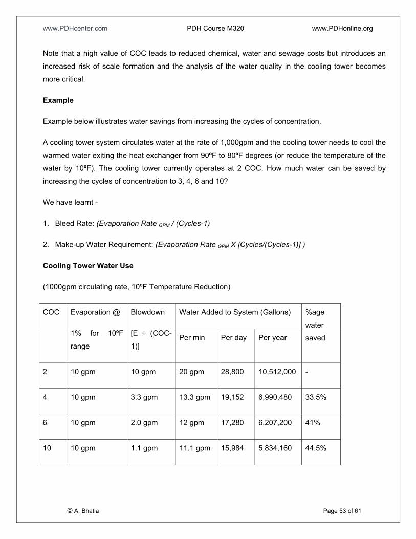
www.PDHcenter.com PDH Course M320 www.PDHonline.org
Note that a high value of COC leads to reduced chemical, water and sewage costs but introduces an
increased risk of scale formation and the analysis of the water quality in the cooling tower becomes
more critical.
Example
Example below illustrates water savings from increasing the cycles of concentration.
A cooling tower system circulates water at the rate of 1,000gpm and the cooling tower needs to cool the
warmed water exiting the heat exchanger from 90ºF to 80ºF degrees (or reduce the temperature of the
water by 10ºF). The cooling tower currently operates at 2 COC. How much water can be saved by
increasing the cycles of concentration to 3, 4, 6 and 10?
We have learnt -
1. Bleed Rate: (Evaporation Rate GPM / (Cycles-1)
2. Make-up Water Requirement: (Evaporation Rate GPM X [Cycles/(Cycles-1)] )
Cooling Tower Water Use
(1000gpm circulating rate, 10ºF Temperature Reduction)
© A. Bhatia Page 53 of 61
Water Added to System (Gallons) COC Evaporation @
1% for 10ºF
range
Blowdown
[E ÷ (COC-
1)] Per min Per day Per year
%age
water
saved
2 10 gpm 10 gpm 20 gpm 28,800 10,512,000 -
4 10 gpm 3.3 gpm 13.3 gpm 19,152 6,990,480 33.5%
6 10 gpm 2.0 gpm 12 gpm 17,280 6,207,200 41%
10 10 gpm 1.1 gpm 11.1 gpm 15,984 5,834,160 44.5%

www.PDHcenter.com PDH Course M320 www.PDHonline.org
Reduction in Treatment Chemical Costs
The 1,000 gpm cooling system evaluated in the examples above can be expected to use 8,761 pounds
of treatment chemicals per year at two cycles of concentration. By reducing the amount of makeup
water, fewer pounds of treatment chemicals are required. Increasing the cycles of concentration from
two to four could save $7,338 per year in chemical costs; increasing the cycles of concentration from
two to six could save $8,980 per year. (Assumes chemical costs at $2.50/lb, and maintenance of 100
ppm treatment in the cooling tower water.)
SECTION 16 – COOLING TOWER OPERATION IN FREEZING WEATHER
Cooling towers used in freezing climates are prone to ice formation, which may jeopardize the
operations. Unacceptable ice can be categorized as either a significant amount of ice that has formed
on the fill thus obstructing the heat transfer or excessive ice in a support region which may threaten the
tower structure. There are three potential causes for ice formation:
Causes:
1) The potential of ice varies directly with the quantity of air flowing through the tower. Reducing the air
flow retards the formation of ice.
2) Where air flow is uncontrolled, the potential for ice formation varies inversely with the heat load
imposed on the tower. A reduced heat load increases the probability that unacceptable ice will form.
3) The potential for ice varies inversely with the amount of water flowing over the fill. A reduced
pumping rate increases the likelihood of unacceptable ice formation.
Remedies:
© A. Bhatia Page 54 of 61
Air-Side Control - Reducing the air flow rate not only helps in retarding the formation of ice but also
helps in reduction or elimination of ice already formed. Single speed fans afford the least opportunity for
airflow variation. Two speed fan motors offer better operating flexibility and should be the minimum
mandatory requirement for towers used in freezing climates. Best ice control is achieved by the use of
automatic variable pitch (AVP) fans or use of variable speed fan motors. Ultimately, severe ice

www.PDHcenter.com PDH Course M320 www.PDHonline.org
formation may require that the fans be reversed for a period of time. This causes the falling water
pattern to be shifted outward, bringing a deluge of relatively warm water in contact with ice formations
for rapid melting. This reverse mode is recommended only for short duration due to possibility of ice
formation on the fan cylinders, fan blades and mechanical equipment.
Water-Side Control – Since the potential for freezing on the fill depends so much upon the incoming
water temperature, provision for total water by-pass directly into the cold water basin is advisable on
mechanical draft towers and mandatory on natural draft towers (due to absence of air control). By-pass
mode should be continued until the total water inventory (including that in the basin) reaches an
acceptable level of usually 80°F. Modulation of by-pass whereby a portion of water is allowed to
continue over the fill should be discouraged unless very fine air-side control is maintained and 2) the
water distribution system has the capability to concentrate water flow to the outboard portions of the fill.
Prevention of Basin Freezing
Cooling tower installations particularly those undergo periods of shutdown (night time, weekends,
holidays, interims of schedule or unscheduled maintenance etc) are susceptible to freezing the cold
water basin, as well all exposed piping. Several effective methods are utilized to prevent freezing,
among which are the following:
1) System Draining – Entire system draining may be considered for small installations, particularly
those on which the cooling tower represents the highest point of the circulating water system. Off
course don’t forget to check the local environmental codes. The exposed portions of the piping must
be traced with electric heating cable.
2) Indoor Tank Method – This method, also referred to as “dry basin operation” allows water in the
tower’s cold water basin to drain continuously into an indoor storage tank.
3) Electric Immersion Heater Method – Determine the potential heat loss from the basin taking into
account the volume of water, ambient temperature and wind velocity and estimate the size of
immersion heater from the formula: Heater kW = Heat loss (Btu/hr) / 3412 (Btu/hr per kWh).
© A. Bhatia Page 55 of 61
4) Steam Heating Method – Steam, if available, may be utilized to supply heat to an inoperative
basin. It may be injected directly into the basin water thorough a commercially available steam
muffler or condensate may be recovered by the use of a closed pipe loop installed in the basin.

www.PDHcenter.com PDH Course M320 www.PDHonline.org
5) By-pass Circulation Method – Running water never freezes. By-pass lines are utilized to create a
circulation loop independent of both the main pump and the cooling tower distribution system. This
is one of the better schemes for any installation, regardless of size, because it protects not only the
cooling tower basin, but the exposed piping as well.
SECTION 17 – COOLING TOWER TESTING
Evaluation of cooling tower performance is based on cooling of a specified quantity of water through a
given range and to a specified temperature approach to the wet-bulb or dry-bulb temperature for which
the tower is designed. Cooling tower capacity is generally considerably very hard to quantify as it
requires the accurate, simultaneous measurement of water flow, inlet and outlet water temperatures,
wet bulb temperature and power consumption. Because exact design conditions are rarely experienced
in operation, estimated performance curves are frequently prepared for a specific installation, and
provide a means for comparing the measured performance with design conditions.
For this reason, the performance testing of small factory assembled cooling towers is seldom done.
These designs just carry certification of compliance to CTI Standard STD-201D. Certification is
important, since even small deviations from the expected design have a substantial impact on the
system over time. For instance, a cooling tower that is 20% deficient elevates the leaving water
temperature by approximately 2.5°F. Typically, this higher water temperature will result in 6% more
energy. For instance in HVAC applications, a 500-ton chiller with energy rating of 2197 kW during peak
conditions, this penalty translates into approximately 17 kW of additional energy usage. The
certification stamp offered by CTI guarantees the performance by reviewing, evaluating and time testing
manufacturer’s submitted product offering and capacity ratings.
The cooling tower industry has largely embraced STD-201 because it helps prevent unqualified
manufacturers from enjoying undeserved sales. System designers and owners also benefit with
predictable performance.
Field Erected Cooling Tower Performance
© A. Bhatia Page 56 of 61
Large projects use field erected cooling towers where unique designs and field assembly practices
necessitates performance testing. All field erected cooling towers should be specified with a specific
test and penalties for failure clearly laid-out in advance. The performance testing is based on the
criteria set forth by Acceptance Test Code (ATC-105) published by the Cooling Technology Institute
www.PDHcenter.com PDH Course M320 www.PDHonline.org
(CTI) and by American Society of Mechanical Engineers (ASME) Power Test Code for Atmospheric
Cooling Equipment (PTC-23).
Testing Parameters
Test data required for the performance evaluation of a mechanical draft cooling tower includes: water
flow rate, hot and cold water temperatures, entering wet bulb temperature, fan power and wind speed.
The testing of a natural draft tower must also include the dry-bulb temperature but, of course, omits the
need for fan power data. Make-up and blowdown water quantities and temperatures, as well as any
miscellaneous water sources may need to be measured, depending upon their effect upon the
aforementioned primary variables. Most testing done today is conducted using data acquisition systems
to measure the temperatures.
1) Temperature Measurements – Air temperatures include both the wet bulb and dry bulb
temperatures. Wet bulb temperatures should be measured with mechanically aspirated
psychrometers, although sling type psychrometers do afford an alternate accurate means of
measuring this variable. All precautions stated in ASME or CTI Test Codes must be exercised. Dry
bulb temperatures are measured with thermometers, RTDs, or thermistors. It is also very important
to recognize the difference between an ambient and entering wet bulb test. Both ASME and CTI
recommend that towers be sized and tested based on entering wet bulb temperatures. The entering
wet bulb temperature attempts to measure the average temperature of all the air entering the tower
regardless of its source. Should mercury-in-glass thermometers be utilized, the major difference is
that less data will be taken and the parameters will typically be measured sequentially.
2) Water Temperature – Water temperatures are measured with thermometers, RTDs or thermistors.
The hot water temperature is normally taken in the distribution basin (cross-flow towers) or in a tap
in the piping carrying water to the tower. The cold water temperatures from the tower can vary
considerably throughout the collection basin, therefore, care must be taken to select a point of
measurement where thorough mixing has occurred. The pump discharge is generally considered to
be satisfactory location.
© A. Bhatia Page 57 of 61
3) Flow Measurements - To measure the water flow rate, a pitot tube traverse of the piping carrying
water to the tower is the most preferred method. Other acceptable means for flow measurements
include the orifice plate, venture tube and flow nozzle, all of which also require laboratory
calibration.

www.PDHcenter.com PDH Course M320 www.PDHonline.org
4) Power Measurements - A wattmeter is used to measure pump and fan input power on mechanical
draft tower systems up to 600 volts. Above 600 volts alternate means must be identified.
In addition, any other factor affecting the towers operation or the data taken must be accounted for.
Examples may include pump discharge pressure, make-up flow and temperature, blow-down flow and
temperature, auxiliary streams entering the collection basin, etc.
Operating Conditions during Test
Current ASME and CTI Test Codes suggest the following limitations to variations from design to be
observed during testing:
Water Rate ±10% of design
Cooling Range ±20% of design
Heat Load ±20% of design
Wet-bulb Temperature ±10°F of design (CTI Test Code)
+5°F, -15°F of design (ASME Test Code)
Dry-bulb Temperature ±20°F of design
Wind Velocity generally less than 10 mph
Fan Power ±10% of design
There will be times when operating or atmospheric conditions will not permit a test to be performed
within above limits. While it is preferable to comply with all these limitations, it is not always possible.
Testing, however, can proceed by mutual agreement among responsible test parties, provided test
conditions are covered by the manufacturer’s performance curves.
Someone desiring a CTI approved test, only the CTI pre-approved licensed testing agencies could
verify and authenticate the test results. The selected test company will provide a calibrated test
instruments for temperature, flow and power measurement. Test results are submitted to CTI for review
and verification and an official test result provided by CTI.
© A. Bhatia Page 58 of 61
For details refer to CTI at www.cti.org and ASME PCT-23 www.asme.org/cns

www.PDHcenter.com PDH Course M320 www.PDHonline.org
SECTION 18- CODES AND GUIDES
The Cooling Tower Institute, CTI, is a non-profit organization based in Houston, TX comprised of
cooling tower users, manufacturers, and related service providers. It is probably best known for its test
specifications and huge library of papers addressing all of cooling tower related subjects.
The American Society of Heating, Refrigeration and Air Conditioning Engineers, ASHRAE, is an
international organization which is also non profit and headquartered in Atlanta, GA. They promote
standards based on extensive research and publish comprehensive books. Most of the weather data,
the design wet bulb temperature, used by system designers comes from ASHRAE publications.
Within the industry, standards for cooling towers are set up by the Cooling Tower Institute (CTI). The CTI
is a self-governing, non-profit technical association dedicated to the improvement of technology, design,
performance and maintenance of cooling towers. When a tower is specified as a CTI code tower, the
following standards become part of the specification (if applicable):
• STD-103 Redwood Lumber Specification
• ATC-105 Acceptance Test Code
• STD-111 Gear Speed Reducers
• STD-114 Douglas fir Lumber Specification
• STD-115 Southern Pine Lumber Specification
• STD-118 Inquiry and Bid Form
• STD-119 Timber Fastener Specification
• STD-127 Asbestos Cement Materials for Application on Industrial Water Cooling Towers
• STD-201 Certification Standard for Commercial Water Cooling Towers
© A. Bhatia Page 59 of 61
SECTION 19 – EXAMPLE

www.PDHcenter.com PDH Course M320 www.PDHonline.org
A Tower cools 1000 GPM from 95º F to 85º F at 72º F wet bulb temperature and operates at 3 cycles of
concentration. Calculate Range, Approach, Heat rejection, Drift loss, Evaporation rate, Bleed rate and
Make up water requirements.
1. Range: (HWT – CWT) = 95 - 85 = 10º F
2. Approach: (CWT – WBT) = 85 - 73 = 13º F
3. Heat Rejection: (Flow GPM X Range ºF X 500) = 1000 x 10 x 500 = 5,000,000 btu’s/hr = 5,000 MBH)
4. Typical Drift Loss: (0.002% X Flow Rate) = 0.00002 X 1000 = 0.02 GPM
5. Evaporation Rate: (Flow GPM X Range ºF / 1,000) = 1000 X 10 / 1,000 = 10 GPM
6. Bleed Rate: (Evaporation Rate GPM / (Cycles-1) = 10 / (3-1) = 5 GPM
7. Make-up Water Requirement: (Evaporation Rate GPM X [Cycles/(Cycles-1)] ) = 10 x 3/2 = 15 GPM
Course Summary
Evaporative water-cooled systems, whether open or closed-circuit, are the best overall heat rejection
solution for most installations. These systems offer design flexibility, save energy, and conserve
resources while protecting and respecting the environment.
The most critical value in determining cooling tower efficiency and size is the wet bulb temperature of
entering air. Wet bulb temperature is a measurement of maximum cooling capability of air and is a
function of the actual (dry bulb) temperature and moisture content (relative humidity) of the air.
Range and Approach are two most important parameters associated with cooling towers. The sizing of
cooling tower varies directly as a function of heat load and inversely as range and approach.
To select a cooling tower, the water flow rate, water inlet temperature, water outlet temperature and
ambient wet bulb temperatures must be known.
© A. Bhatia Page 60 of 61
The cooling tower could be natural draft that finds usage mainly in power generation facilities. Most of
the industry, process or air-conditioning applications rely on the use of mechanical draft-cooling towers.

www.PDHcenter.com PDH Course M320 www.PDHonline.org
The mechanical draft cooling towers are further classified as the counter-flow or the cross –flow type
depending upon the ‘Fill’ arrangement and the way air comes in contact with water.
The cooling towers use wood, galvanized steel, stainless steel, concrete and fiberglass as the major
fabrication materials.
The other important factors that guide the overall performance of the system include the layout &
installation considerations to keep the tower free from obstructions, health hazards such as Legionella
disease, water treatment, energy efficiency, environment and acoustic concerns.
© A. Bhatia Page 61 of 61
The testing and performance of cooling tower is governed by the guidelines of Cooling Tower Institute
(CTI) standards. The cooling tower industry continues to develop innovative products and services to
meet the evolving needs of new and existing facilities.

www.PDHcenter.com PDH Course M320 www.PDHonline.org
GLOSSARY
The following terms are commonly used in cooling tower science, many of which are unique to the
cooling tower industry:
1) ACFM - The actual volumetric flow rate of air-vapor mixture, cubic feet of air moved per minute.
Unit: cu ft per min
2) Air Horsepower - The power output developed by a fan in moving a given air rate against a given
resistance. Unit: hp. Symbol: AHP
3) Air lnlet - Opening in a cooling tower through which air enters; sometimes referred to as the
louvered face on induced draft towers.
4) Air Rate - Mass flow of dry air per square foot of cross - sectional area in the tower's heat transfer
region per hour. Unit: lb per sq ft per hr. Symbol: G'.(See Total Air Rate).
5) Air Travel - Distance which air travels in its passage through the fill. Measured vertically on
counter-flow towers and horizontally on cross-flow towers. Unit: ft.
6) Air Velocity - Velocity of air-vapor mixture through a specific region of the tower (i.e. the fan).
Unit: ft per min. Symbol: V
7) Ambient Wet-Bulb Temperature - The wet-bulb temperature of the air encompassing a cooling
tower not including any temperature contribution by the tower itself. Generally measured upwind
of a tower in a number of locations sufficient to account for all extraneous sources of heat. Unit:
°F. Symbol: AWB
8) Approach - Difference between the cold water temperature and either the ambient or entering
wet-bulb temperature. (CW-EWB=A) Unit: ºF
9) Atmospheric - Refers to the movement of air through a cooling tower purely by natural means, or
by the aspirating effect of water flow.
© A. Bhatia Page 62 of 61
10) Automatic Variable-Pitch Fan - A propeller type fan whose hub incorporates a mechanism
which enables the fan blades to be re-pitched simultaneously and automatically. They are used
on cooling towers and air-cooled heat exchangers to trim capacity and/or conserve energy.

www.PDHcenter.com PDH Course M320 www.PDHonline.org
11) Basin - See "Collection Basin" and "Distribution Basin".
12) Basin Curb - Top level of the cold water basin retaining wall; usually the datum from which
pumping head and various elevations of the tower are measured.
13) Bay - The area between adjacent transverse and longitudinal framing bents.
14) Bent - A transverse or longitudinal line of structural framework composed of columns, girts, ties,
and diagonal bracing members.
15) Bleed-Off or Blowdown - Water discharged from the system to control concentrations of salts or
other impurities in the circulating water. Units % of circulating water rate or gpm.
16) Blower - A squirrel-cage (centrifugal) type fan; usually applied for operation at higher-than-normal
static pressures.
17) Blow-out - Water droplets blown out of the cooling tower by wind, generally at the air inlet
openings. Water may also be lost, in the absence of wind, through splashing or misting. Devices
such as wind screens, louvers, splash deflectors and water diverters are used to limit these
losses.
18) Brake Horsepower - The actual power output of a motor, turbine, or engine. Unit: hp. Symbol:
bhp.
19) BTU (British Thermal Unit) - The amount of heat gain (or loss) required to raise (or lower) the
temperature of one pound of water one degree (1º) F
20) Capacity - The amount of water (gpm) that a cooling tower will cool through a specified range, at
a specified approach and wet-bulb temperature. Unit: gpm.
21) Casing - Exterior enclosing wall of a tower exclusive of the louvers.
22) Cell - Smallest tower subdivision which can function as an independent unit with regard to air and
water flow; it is bounded by either exterior walls or partition walls. Each cell may have one or more
fans and one or more distribution systems.
© A. Bhatia Page 63 of 61
23) CFM - The volumetric flow rate of air-vapor mixture, cubic feet of air moved per minute. Unit: cu ft
per min.

www.PDHcenter.com PDH Course M320 www.PDHonline.org
24) Chimney - See "Shell".
25) Circulating Water Rate - Quantity of hot water entering the cooling tower. Unit: gpm.
26) Cold Water Temperature - Temperature of the water leaving the collection basin, exclusive of
any temperature effects incurred by the addition of make-up and/or the removal of blowdown.
Unit: °F. Symbol: CW.
27) Collection Basin - Vessel below and integral with the tower where water is transiently collected
and directed to the sump or pump suction line.
28) Counter-flow - Air flow direction through the fill is countercurrent to that of the falling water.
29) Crossflow - Air flow direction through the fill is essentially perpendicular to that of the falling
water.
30) Distribution Basin - Shallow pan-type elevated basin used to distribute hot water over the tower
fill by means of orifices in the basin floor. Application is normally limited to crossflow towers.
31) Distribution System - Those parts of a tower beginning with the inlet connection which distribute
the hot circulating water within the tower to the points where it contacts the air for effective
cooling. May include headers, laterals branch arms, nozzles, distribution basins, and flow-
regulating devices.
32) Double-Flow - A crossflow cooling tower where two opposed fill banks are served by a common
air plenum.
33) Drift - Circulating water lost from the tower as liquid droplets entrained in the exhaust air stream.
Units: % of circulating water rate or gpm.
34) Drift Eliminators - An assembly of baffles or labyrinth passages through which the air passes
prior to its exit from the tower, for the purpose of removing entrained water droplets from the
exhaust air.
35) Driver - Primary drive for the fan drive assembly.
© A. Bhatia Page 64 of 61
36) Dry-Bulb Temperature - The temperature of the entering or ambient air adjacent to the cooling
tower as measured with a dry-bulb thermometer. Unit: ºF. Symbol: DB.

www.PDHcenter.com PDH Course M320 www.PDHonline.org
37) Entering Wet-Bulb Temperature - The wet-bulb temperature of the air actually entering the
tower, including any effects of recirculation. In testing, the average of multiple readings taken at
the air inlets to establish a true entering wet-bulb temperature. Unit ºF. Symbol: EWB.
38) Evaluation - A determination of the total cost of owning a cooling tower for a specific period of
time. Includes first cost of tower and attendant devices, cost of operation, cost of maintenance
and/or repair, cost of land use, cost of financing, etc., all normalized to a specific point in time.
39) Evaporation Loss - Water evaporated from the circulating water into the air stream in the cooling
process. Units: % of circulating water rate or gpm.-
40) Exhaust (Exit) Wet-Bulb Temperature - See "Leaving Wet-Bulb Temperature".
41) Fan Cylinder - Cylindrical or venturi-shaped structure in which a propeller fan operates.
Sometimes referred to as a fan "stack" on larger towers.
42) Fan Deck - Surface enclosing the top structure of an induced draft cooling tower, exclusive of the
distribution basins on a crossflow tower.
43) Fan Pitch - The angle which the blades of a propeller fan make with the plane of rotation,
measured at a prescribed point on each blade. Unit: degrees.
44) Fan Scroll - Convolute housing in which a centrifugal (blower) fan operates.
45) Fill - That portion of a cooling tower which constitutes its primary heat transfer surface.
Sometimes referred to as "packing".
46) Fill Cube - (1) Counterflow: The amount of fill required in a volume one bay long by one bay wide
by an air travel high. Unit: cu ft. (2) Crossflow: The amount of fill required in a volume one bay
long by an air travel wide by one story high. Unit: cu ft.
47) Fill Deck - One of a succession of horizontal layers of splash bars utilized in a splash-filled
cooling tower. The number of fill decks constituting overall fill height, as well as the number of
splash bars incorporated within each fill deck, establishes the effective primary heat transfer
surface.
© A. Bhatia Page 65 of 61
48) Fill Sheet - One of a succession of vertically-arranged, closely-spaced panels over which flowing
water spreads to offer maximum surface exposure to the air in a film-filled cooling tower. Sheets

www.PDHcenter.com PDH Course M320 www.PDHonline.org
may be flat, requiring spacers for consistent separation; or they may be formed into corrugated,
chevron, and other patterns whose protrusions provide proper spacing, and whose convolutions
provide increased heat-transfer capability.
49) Film-Filled - Descriptive of a cooling tower in which film-type fill is utilized for the primary heat-
transfer surface.
50) Float Valve - A valve which is mechanically actuated by a float. Utilized on many cooling towers
to control make-up water supply.
51) Flow-Control Valves - Manually controlled valves which are used to balance flow of incoming
water to all sections of the tower.
52) Flume - A trough which may be either totally enclosed, or open at the top. Flumes are sometimes
used in cooling towers for primary supply of water to various sections of the distribution system.
53) Fogging - A reference to the visibility and path of the effluent air stream after having exited the
cooling tower. If visible and close to the ground it is referred to as "fog". If elevated it is normally
called the "plume".
54) Forced Draft - Refers to the movement of air under pressure through a cooling tower. Fans of
forced draft towers are located at the air inlets to "force" air through the tower.
55) Heat Load - Total heat to be removed from the circulating water by the cooling tower per unit
time. Units: Btu per min. or Btu per hr.
56) Height - On cooling towers erected over a concrete basin, height is measured from the elevation
of the basin curb. "Nominal" heights are usually measured to the fan deck elevation, not including
the height of the fan cylinder. Heights for towers on which a wood, steel, or plastic basin, is
included within the manufacturer's scope of supply are generally measured from the lowermost
point of the basin, and are usually overall of the tower. Unit: ft.
57) Horsepower - The power output of a motor, turbine, or engine (also see Brake Horsepower).
Unit: hp. Symbol: hp.
© A. Bhatia Page 66 of 61
58) Hot Water Temperature - Temperature of circulating water entering the cooling tower's
distribution system. Unit: F. Symbol: HW.

www.PDHcenter.com PDH Course M320 www.PDHonline.org
59) Hydrogen Ion Concentration - See "pH".
60) lnduced Draft - Refers to the movement of air through a cooling tower by means of an induced
partial vacuum. Fans of induced draft towers are located at the air discharges to "draw" air
through the tower.
61) Inlet Wet-Bulb Temperature - See "Entering Wet-Bulb Temperature".
62) Interference - The thermal contamination of a tower's inlet air by an external heat source. (i.e. the
discharge plume of another cooling tower.)
63) Leaching - The loss of wood preservative chemicals by the washing action of the water flowing
through a wood structure cooling tower.
64) Leaving Wet-Bulb Temperature - Wet-bulb temperature of the air discharged from a cooling
tower. Unit: F. Symbol: LWB.
65) Length - For crossflow towers, length is always perpendicular to the direction of air flow through
the fill (air travel), or from casing to casing. For counterflow towers, length is always parallel to the
long dimension of a multi-cell tower, and parallel to the intended direction of cellular extension on
single-cell towers. Unit: ft.
66) Liquid-to-Gas Ratio - A ratio of the total mass flows of water and dry air in a cooling tower. (See
Total Air Rate & Total Water Rate) Unit: lb per lb. Symbol: L/G.
67) Longitudinal - Pertaining to occurrences in the direction of tower length.
68) Louvers - Blade or passage type assemblies installed at the air inlet face of a cooling tower to
control water splashout and/or promote uniform air flow through the fill. In the case of film-type
crossflow fill, they may be integrally molded to the fill sheets.
69) Make-Up - Water added to the circulating water system to replace water lost by evaporation, drift,
windage, blowdown, and leakage. Units: % of circulating water rate or gpm.
© A. Bhatia Page 67 of 61
70) Mechanical Draft - Refers to the movement of air through a cooling tower by means of a fan or
other mechanical device.

www.PDHcenter.com PDH Course M320 www.PDHonline.org
71) Module - A preassembled portion or section of a cooling tower cell. On larger factory-assembled
towers two or more shipped modules may require joining to make a cell.
72) Natural Draft - Refers to the movement of air through a cooling tower purely by natural means.
Typically, by the driving force of a density differential.
73) Net Effective Volume - That portion of the total structural volume within which the circulating
water is in intimate contact with the flowing air. Unit: cu ft.
74) Noise - Sound energy emitted by a cooling tower and heard (recorded) at a given distance and
direction. The sound is generated by the impact of falling water, by the movement of air by fans,
the fan blades moving in the structure, and the motors, gearboxes or drive belts.
75) Nozzle - A device used for controlled distribution of water in a cooling tower. Nozzles are
designed to deliver water in a spray pattern either by pressure or by gravity flow.
76) Packing - See "Fill".
77) Partition - An interior wall subdividing the tower into cells or into separate fan plenum chambers.
Partitions may also be selectively installed to reduce windage water loss.
78) Performance - See "Capacity".
79) pH - A scale for expressing acidity or alkalinity of the circulating or make-up water. A pH below
7.0 indicates acidity and above 7.0 indicates alkalinity. A pH of 7.0 indicates neutral water.
80) Pitot Tube - An instrument that operates on the principle of differential pressures and is used to
measure fluid flow.
81) Plenum Chamber - The enclosed space between the drift eliminators and the fan in induced draft
towers, or the enclosed space between the fan and the fill in forced draft towers.
© A. Bhatia Page 68 of 61
82) Plume - The stream of saturated exhaust air leaving the cooling tower. The plume is visible when
water vapor it contains condenses in contact with cooler ambient air, like the saturated air in one's
breath fogs on a cold day. Under certain conditions, a cooling tower plume may present fogging or
icing hazards to its surroundings. Note that the water evaporated in the cooling process is "pure"
water, in contrast to the very small percentage of drift droplets or water blown out of the air inlets.

www.PDHcenter.com PDH Course M320 www.PDHonline.org
83) Psychrometer - An instrument incorporating both a dry-bulb and a wet-bulb thermometer, by
which simultaneous dry-bulb and wet-bulb temperature readings can be taken.
84) Pump Head - See "Tower Pumping Head".
85) Range - Difference between the hot water temperature and the cold water temperature (HW - CW
= R) Unit: F.
86) Recirculation - Describes a condition in which a portion of the tower's discharge air re-enters the
air inlets along with the fresh air. Its effect is an elevation of the average entering wet-bulb
temperature compared to the ambient.
87) Riser - Piping which connects the circulating water supply line, from the level of the base of the
tower or the supply header, to the tower's distribution system. Shell - The chimney-like structure,
usually hyperbolic in cross-section, utilized to induce air flow through a natural draft tower.
Sometimes referred to as a "stack" or "veil".
88) Speed Reducer - A mechanical device incorporated between the driver and the fan of a
mechanical draft tower, designed to reduce the speed of the driver to an optimum speed for the
fan. The use of geared reduction units predominates in the cooling tower industry, although
smaller towers will utilize differential pulleys and V-belts for the transmission of relatively low
power.
89) Splash Bar - One of a succession of equally-spaced horizontal bars comprising the splash
surface of a fill deck in a splash-filled cooling tower. Splash bars may be flat, or may be formed
into a shaped cross-section for improved structural rigidity and/or improved heat transfer
capability. When flat, they are sometimes referred to as "slats" or "lath".
90) Splash-Filled - Descriptive of a cooling tower in which splash-type fill is used for the primary heat
transfer surface.
91) Spray-Filled - Descriptive of a cooling tower which has no fill, with water-to-air contact depending
entirely upon the water break-up and pattern afforded by pressure spray nozzles.
© A. Bhatia Page 69 of 61
92) Stack - An extended fan cylinder whose primary purpose is to achieve elevation of the discharge
plume.

www.PDHcenter.com PDH Course M320 www.PDHonline.org
93) Stack Effect - Descriptive of the capability of a tower shell or extended fan cylinder to induce air
(or aid in its induction) through a cooling tower.
94) Standard Air - Air having a density of 0.075 lb per cu ft; essentially equivalent to 70ºF dry air at
29.92 in Hg barometric pressure.
95) Story - The vertical dimension between successive levels of horizontal framework ties, girts,
joists, or beams. Story dimensions vary depending upon the size and strength characteristics of
the framework material used. Unit: ft.
96) Sump - A depressed chamber either below or alongside (but contiguous to) the collection basin,
into which the water flows to facilitate pump suction. Sumps may also be designed as collection
points for silt and sludge to aid in cleaning.
97) Total Air Rate - Total mass flow of dry air per hour through the tower. Unit: lb per hr. Symbol: G.
98) Total Water Rate - Total mass flow of water per hour through the tower. Unit: lb per hr. Symbol:
L.
99) Tower Pumping Head - The static lift from the elevation of the basin curb to the centerline
elevation of the distribution system inlet plus the total pressure (converted to ft of water)
necessary at that point to effect proper distribution of the water to its point of contact with the air.
Unit: ft of water.
100) Transverse - Pertaining to occurrences in the direction of tower width.
101) Velocity Recovery Fan Cylinder - A fan cylinder on which the discharge portion is extended in
height and outwardly flared. Its effect is to decrease the total head differential across the fan,
resulting in either an increase in air rate at constant horsepower, or a decrease in horsepower at
constant air rate.
102) Water Loading - Circulating water rate per horizontal square foot of fill plan area of the cooling
tower. Unit: gpm per sq ft.
© A. Bhatia Page 70 of 61
103) Water Rate - Mass flow of water per square foot of fill plan area of the cooling tower per hour.
Unit: lb per sq ft per hr. Symbol: L.
www.PDHcenter.com PDH Course M320 www.PDHonline.org
104) Wet-Bulb Temperature - The temperature of the entering or ambient air adjacent to the cooling
tower as measured with a wet-bulb thermometer. Unit: F. Symbol: WB.
105) Wet-Bulb Thermometer - A thermometer whose bulb is encased within a wetted wick.
106) Windage - Water lost from the tower because of the effects of wind. Sometimes called "blowout".
107) Wind Load - The load imposed upon a structure by a wind blowing against its surface. Unit: lb per
sq ft.
© A. Bhatia Page 71 of 61