Embed Size (px)
Citation preview

Cooling Systems and Thermal Energy Storage
Kent Peterson, PE, LEED AP
Sponsored By
Cooling Systems and Thermal Energy Storage Page 1 Copyright APPA 2009

Published by APPA:APPA is the association of choice serving educational facilities professionals. APPA's mission is tosupport educational excellence with quality leadership and professional management througheducation, research, and recognition.
Reprint Statement:Except as permitted under copyright law, no part of this chapter may be reproduced, stored in aretrieval system, distributed, or transmitted in any form or by any means - electronic, mechanical,photocopying, recording, or otherwise - without the prior written permission of APPA.
From APPA Body of Knowledge APPA: Leadership in Educational Facilities, Alexandria, Virginia, 2009This BOK is constantly being updated. For the latest version of this chapter, please visitwww.appa.org/BOK .
This chapter is made possible by
APPA1643 Prince StreetAlexandria, Virginia 22314-2818www.appa.org
Copyright © 2009 by APPA. All rights reserved.
Cooling Systems and Thermal Energy Storage Page 2 Copyright APPA 2009
Cooling Systems and Thermal Energy Storage
Introduction
Central cooling systems are an attractive method for cooling individual buildings by connectingthem onto a common cooling loop. Central cooling systems can displace several small localizedchillers with central systems that have options that are not feasible at individual sites.
Facilities managers should consider a number of factors when evaluating the merits of centralcooling systems. These factors include annual operating costs, annual use of energy and domesticwater, the age and condition of the existing system, and availability of capital.
Advantages of Central Cooling Systems
Central chiller plants offer several advantages over individual building air conditioning systems.Central chiller plants can take advantage of the diversity factor in the sizing of equipment andoperation of the plant, as all connected loads will not peak at the same time. Less capital is requiredfor central cooling equipment than for equipment in many individual buildings. Operations andmaintenance (O&M) staffing costs are minimized and easier to control due to the centralizedequipment location. Increased efficiencies are possible with large heating and cooling equipment,which reduces operating cost per unit of energy output. Part-load performance efficiencies aresubstantially improved by the ability to meet the system load with the most efficient equipment.Continuous and accurate monitoring of operating efficiencies is practical when the equipment iscentralized. Single-point delivery of purchased utilities allows for favorable rates to a large-volumecustomer. Multiple fuel sources can also be a practical alternative.
Disadvantages of Central Cooling Systems
Central systems present some disadvantages over cooling equipment distributed in individualbuildings. Thermal and hydraulic losses occur in large-distribution networks. These losses must beevaluated against the increased generating efficiencies of a central plant. The initial construction costrequires a large capital investment. Therefore, the most cost-effective options may have to bedeferred if capital cannot be secured.
Central Plant Design
Major equipment such as chillers, pumps, and cooling towers should not be purchased without a setof detailed specifications on the items being purchased. These specifications establish the minimumquality and the maximum energy consumption that will be acceptable for each item. The equipmentshould not be accepted until it is tested to demonstrate compliance for capacity and performance. Itis important to remember that the efficiency of a central plant is measured by dividing the energysupplied by all the energy inputs (chillers, pumps, and cooling towers). The goal is to deliver therequired cooling throughout the year with the least amount of energy input. It is therefore necessaryto understand how the central cooling plant will perform at all anticipated load conditions.
A thorough understanding of the major equipment used in these plants is required to maximize theperformance and economic benefits of upgraded or new chilled water plants. This chapter providesan in-depth look at this equipment, as well as essential information on how the components relate to
Cooling Systems and Thermal Energy Storage Page 3 Copyright APPA 2009
one another, how they are controlled, and their physical and operational limitations. This chapterdiscusses
the basic refrigeration cycle;the components commonly used in commercially available packaged water chillers;methods of heat rejection, with an emphasis on cooling towers and air-cooled refrigerantcondensers;the characteristics of different types of pumps;pump and system curves, with an emphasis on understanding the nature of variable-speedpumping.
Refrigeration Cycle
The refrigeration cycle, also known as the Carnot cycle, is the fundamental thermodynamic basis forremoving heat from buildings and rejecting it to the outdoors. The cycle’s four basic components arethe
compressor,evaporator,condenser, andthrottling device.
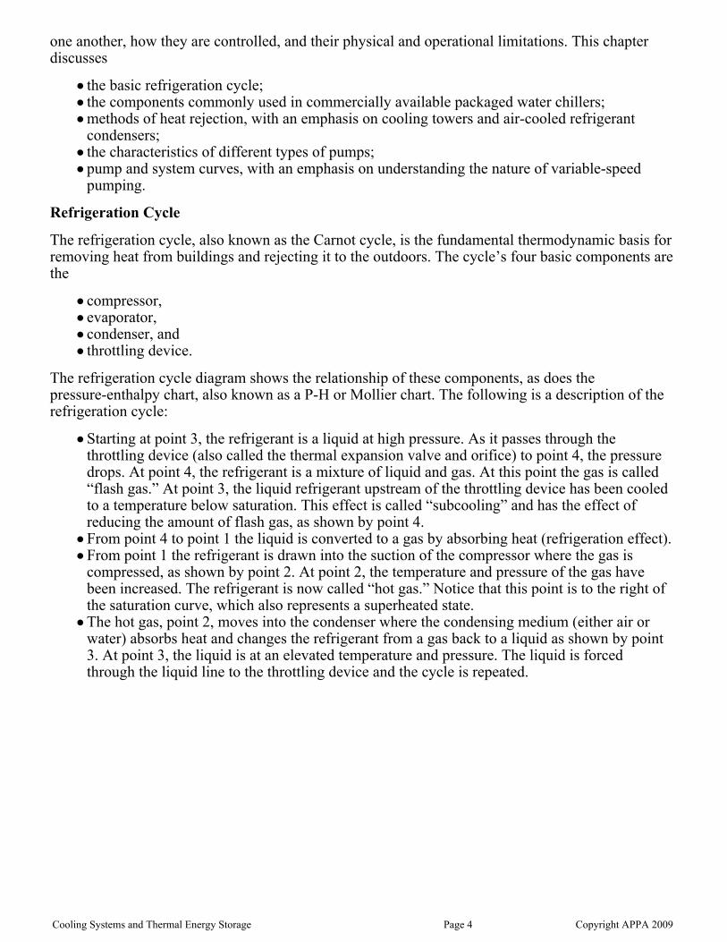
The refrigeration cycle diagram shows the relationship of these components, as does thepressure-enthalpy chart, also known as a P-H or Mollier chart. The following is a description of therefrigeration cycle:
Starting at point 3, the refrigerant is a liquid at high pressure. As it passes through thethrottling device (also called the thermal expansion valve and orifice) to point 4, the pressuredrops. At point 4, the refrigerant is a mixture of liquid and gas. At this point the gas is called“flash gas.” At point 3, the liquid refrigerant upstream of the throttling device has been cooledto a temperature below saturation. This effect is called “subcooling” and has the effect ofreducing the amount of flash gas, as shown by point 4.From point 4 to point 1 the liquid is converted to a gas by absorbing heat (refrigeration effect). From point 1 the refrigerant is drawn into the suction of the compressor where the gas iscompressed, as shown by point 2. At point 2, the temperature and pressure of the gas havebeen increased. The refrigerant is now called “hot gas.” Notice that this point is to the right ofthe saturation curve, which also represents a superheated state.The hot gas, point 2, moves into the condenser where the condensing medium (either air orwater) absorbs heat and changes the refrigerant from a gas back to a liquid as shown by point3. At point 3, the liquid is at an elevated temperature and pressure. The liquid is forcedthrough the liquid line to the throttling device and the cycle is repeated.
Cooling Systems and Thermal Energy Storage Page 4 Copyright APPA 2009

Figure 1. The Refrigeration Cycle and Enthalpy Chart
Chillers
Many chiller types are available to match the specific needs of a given chiller plant. Factors affectingchiller selection include energy sources, prime movers, physical size, load requirements, anticipatedload profile throughout the year, and refrigerant selections. Energy sources, prime movers, andrefrigerants are discussed separately later in this subchapter.
Types
The three types of chillers most commonly used in central chiller plants are rotary, centrifugal, andabsorption. A wide variety of chiller combinations can occur, especially in plants that haveundergone multiple phases of expansion.
Rotary Screw Type Chillers
There are a number of types of rotary compressors used in the heating, ventilation, and air
Cooling Systems and Thermal Energy Storage Page 5 Copyright APPA 2009

conditioning (HVAC) industry, including scroll, single blade (fixed vane), rotating vane, and screw(helical-rotary). Single blade and rotating vane compressors are generally used in smallerapplications and will not be discussed further here. Scroll compressors are largely replacingreciprocating compressors for the smaller chiller sizes (although there are scroll machines up to 400tons in capacity). In packaged water chillers the most commonly used compressor is the screw.There are two types in use today: the single screw and the multiple screw.
Single Screw
The single screw consists of a single cylindrical main rotor that works with a pair of gaterotors. Thecompressor is driven through the main rotor shaft and the gaterotors follow by direct meshing action.As the main rotor turns, the teeth of the gaterotor, the sides of the screw, and the casing traprefrigerant. As rotation continues, the groove volume decreases and compression occurs. Since thereare two gaterotors, each side of the screw acts independently. Single-screw compressors are notedfor long bearing life as the bearing loads are inherently balanced. Some single-screw compressorshave a centrifugal economizer built into them. This economizer has an intermediate pressurechamber that takes the flash gas (via a centrifugal separator) from the liquid and injects it into aclosed groove in the compression cycle, with the result of increased efficiency.
The single screw is controlled from a slide valve in the compressor casing that changes the locationwhere the refrigerant is introduced into the compression zone. This causes a reduction in groovevolume and hence the volume of gas varies (variable compressor displacement). The machines arefully modulating. The single screw has slide valves on each side that can be operated independently.This allows the machine to have a very low turndown with good part-load energy performance.
Twin Screw
The twin screw is the most common of the multiple screw compressors. The twin screw is thecommon designation for double helical rotary screw compressor. The twin screw consists of twomating helically grooved rotors, one male and the other female. Either the male or female rotor canbe driven. The other rotor either follows the driven rotor on a light oil film or is driven withsynchronized timing gears. At the suction side of the compressor, the gas fills a void between themale and female rotors. As the rotors turn, the male and female rotors mesh and work with thecasing to trap the gas. Continued rotation decreases the space between lobes and the gas iscompressed. The gas is discharged at the end of the rotors.
The twin screw has a slide valve for capacity control, located near the discharge side of the rotors,which bypasses a portion of the trapped gas back to the suction side of the compressor.
VSD Controls
In recent years manufacturers have introduced screw chillers with variable-speed drive (VSD)controls. In addition to great part-load performance, these chillers offer significantly reduced noiseand wear at off-design conditions.
Centrifugal Chillers
Centrifugal chillers are by far the most popular chiller type in central cooling systems. They areavailable in sizes ranging from 90 to 10,000 tons. They are simple to operate, reliable, compact, andrelatively quiet; have low vibration; and are designed for long life with low maintenance.
Centrifugal compressors are dynamic compression devices (as opposed to positive displacement)that on a continuous basis exchange angular momentum between a rotating mechanical element and
Cooling Systems and Thermal Energy Storage Page 6 Copyright APPA 2009

a steadily flowing fluid. Like centrifugal pumps, centrifugal chillers have an impeller that rotates athigh speed. The molecules of refrigerant enter the rotating impeller in the axial direction and aredischarged radially at a higher velocity. The dynamic pressure of the refrigerant obtained by thehigher velocity is converted to static pressure through a diffusion process that occurs in thestationary discharge or diffuser portion of the compressor just outside the impeller.
A centrifugal compressor can be single stage (having only one impeller) or multistage (having twoor more impellers). On a multistage centrifugal compressor, the discharge gas from the first impelleris directed to the suction of the second impeller, and so on for as many stages as there are. Like therotary compressor, multistage centrifugals can incorporate economizers, which take flash gas fromthe liquid line at intermediate pressures and feed this into the suction at various stages ofcompression. The result is a significant increase in energy efficiency.
Like reciprocating compressors, centrifugal compressors can be either open or hermetic. Opencentrifugal compressors have the motors located outside the casings with the shaft penetrating thecasing through a seal. Hermetic centrifugal compressors have the motor and compressor fullycontained within the same housing, with the motor in direct contact with the refrigerant. Because thedischarge pressure developed by the compressor is a function of the velocity of the tip of theimpeller, for a given pressure, the faster impeller speed, the smaller the diameter needs to be.Similarly, for a given pressure, the more stages of compression there are, the smaller the impellerdiameter needs to be. With these variables in mind, some manufacturers have chosen to use geardrives to increase the speed of a smaller impeller, while other manufacturers use direct drives withlarger impellers and/or multiple stages. There are pros and cons to both systems, but direct drivemachines have fewer moving parts and fewer bearings and are generally simpler machines. Thecapacity of centrifugal compressors is controlled by three methods. The most common is to use inletguide vanes or prerotation vanes. The adjustable vanes are located in the suction line at the eye ofthe impeller and swirl the entering refrigerant in the direction of rotation. This changes thevolumetric flow characteristics of the impeller, providing the basis for unloading.
A second control method is to vary the speed of the impeller in conjunction with using inlet guidevanes. Not unlike a variable-speed fan or pump, reducing the impeller speed produces extremelygood part-load energy characteristics. The impeller must produce an adequate pressure differential(lift) to move the refrigerant from the low-pressure side (evaporator) to the high-pressure side(condenser). It is this lift that determines the minimum speed of the impeller. The lower the lift, thatis, the closer the temperature difference between the evaporator and condenser, the more slowly theimpeller can rotate. When the impeller is at the slowest possible speed, further reductions in capacityare obtained by using the inlet guide vanes. With VSDs and aggressive water temperature resetschedules, centrifugal compressors can produce the most energy-efficient part-load performance ofany refrigerant compressor. It is important to note that centrifugal compressors with VSDs use boththe VSD and inlet vanes for control. The inlet vanes are used to prevent the chiller from getting intosurge. For efficient operation the controls must either dynamically measure or model surge so thatthe bulk of the unloading can be done by the VSD. This is particularly important with primary-onlyvariable-flow plants as some manufacturers' systems use load as an input to the surge map and theymeasure only temperature and not flow. There have been cases where VSD minimums have to beset at 40 percent or higher to prevent the chiller from tripping from surge at low flows.
As described for the screw chillers above, centrifugal chillers with VSDs have both lower noise andreduced wear at off-design conditions.
A third method of capacity control for the centrifugal chiller is hot gas bypass (HGBP). Like othertypes of compressors, HGBP can be used to unload a machine to zero load by directing the hot gasfrom the compressor discharge back into the suction. There are no part-load energy savings withHGBP. It is used only as a last resort when very low turndown is required and cycling the machineon/off would not produce acceptable results.
Cooling Systems and Thermal Energy Storage Page 7 Copyright APPA 2009

One of the characteristics of the centrifugal compressor is that it can “surge.” Surge is a conditionthat occurs when the compressor is required to produce high lift at low volumetric flow. Centrifugalcompressors must be controlled to prevent surge, and this is a limit on part-load performance.During a surge condition, the refrigerant alternately moves backward and forward through thecompressor, creating a great deal of noise, vibration, and heat. Prolonged operation of the machine insurge condition can lead to failure. Surge is relatively easy to detect in that the electrical current tothe compressor will alternately increase and decrease with the changing refrigerant flow. Just beforegoing into surge, the compressor may exhibit a property called “incipient surge” in which themachine gurgles and churns. This is not harmful to the compressor but may create unwantedvibration. The electrical current does not vary during incipient surge.
Absorption Chillers
Absorption chillers are used in many central plant applications. They are available in sizes rangingfrom 100 to 1,500 tons and are usually operated by low-pressure steam or hot water or are directlyfired with natural gas. The higher O&M costs associated with these chillers, compared with those ofcompressor-type units, usually make them uneconomical to use except where electric power isexpensive, where fuel costs are low, or when balancing electrical and thermal loads in cogenerationfacilities.
The absorption process, while appearing quite complex, is in reality the same refrigeration processdiscussed previously except the compressor has been replaced with an absorber, generator, pump,and recuperative heat exchanger. The following description is based on lithium-bromide and water,which is the most common process among several possibilities. In the absorption refrigeration cycle,the low-pressure (high vacuum) refrigerant (water) in the evaporator migrates to the lower pressureabsorber where it is “soaked up” by a solution of lithium-bromide. While mixed with thelithium-bromide the vapor condenses and releases the heat of vaporization picked up in theevaporator. This heat is transferred to condenser water and rejected out the cooling tower. Thelithium-bromide and refrigerant solution (weak solution) are pumped to a heat exchanger (generator)where the refrigerant is boiled off and the lithium-bromide (strong solution) returns to theevaporator. As the hot lithium-bromide (strong solution) returns to the evaporator, a heat exchangercools the liquid with the cool mixture of lithium-bromide and refrigerant (weak solution). Theboiled-off refrigerant migrates to the cooler condenser, where it is condensed back into a liquid andreturned to the evaporator to start the cycle again.
Absorption machines can be direct-fired or indirect-fired. The direct-fired absorber has an integralcombustion heat source that is used in the primary generator. An indirect-fired absorber uses steamor hot water from a remote source.
Cooling Systems and Thermal Energy Storage Page 8 Copyright APPA 2009

Figure 2. Absorption Refrigeration Cycle
A double-effect absorption process is similar to that described above except that a generator,condenser, and heat exchanger are added. The refrigerant vapor from the primary generator runsthrough a heat exchanger (secondary generator) before entering the condenser. The secondarygenerator with the hot vapor on one side of the heat exchanger boils some of the lithium-bromideand refrigerant solution (weak solution), creating the double effect. The double-effect absorptionprocess is significantly more energy efficient than the single-effect absorption process.
Cooling Systems and Thermal Energy Storage Page 9 Copyright APPA 2009
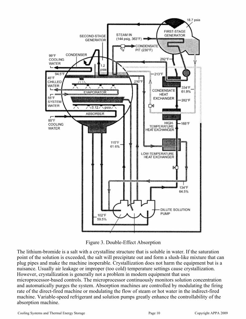
Figure 3. Double-Effect Absorption
The lithium-bromide is a salt with a crystalline structure that is soluble in water. If the saturationpoint of the solution is exceeded, the salt will precipitate out and form a slush-like mixture that canplug pipes and make the machine inoperable. Crystallization does not harm the equipment but is anuisance. Usually air leakage or improper (too cold) temperature settings cause crystallization.However, crystallization is generally not a problem in modern equipment that usesmicroprocessor-based controls. The microprocessor continuously monitors solution concentrationand automatically purges the system. Absorption machines are controlled by modulating the firingrate of the direct-fired machine or modulating the flow of steam or hot water in the indirect-firedmachine. Variable-speed refrigerant and solution pumps greatly enhance the controllability of theabsorption machine.
Cooling Systems and Thermal Energy Storage Page 10 Copyright APPA 2009

Refrigerants
To work properly, refrigerants must have low toxicity, low flammability, and a long atmosphericlife. Recently, refrigerants have come under increased scrutiny by scientific, environmental, andregulatory communities because of the environmental impacts attributed to their use. Somerefrigerants — particularly chlorofluorocarbons (CFCs) — are believed to destroy stratosphericozone. The relative ability of a refrigerant to destroy stratospheric ozone is called its ozone depletionpotential (ODP).
CFCs are being phased out according to the 1987 Montreal Protocol. The production of CFCs indeveloped countries ceased in 1995, and their most common replacement, halogenatedchlorofluorocarbons (HCFCs), are due for phase-out in the 21st century. Replacements are currentlybeing developed for HCFC R-123 and HCFC R-22, which are commonly used in the industry. Forall practical purposes, however, HCFCs should be available well into the middle of the 21st centuryand certainly within the lifetimes of machines currently being manufactured.
The global warming potential (GWP) of refrigerants is another significant environmental issue.Gases that absorb infrared energy enhance the “greenhouse” effect in the atmosphere, leading to thewarming of the earth. Refrigerants have been identified as “greenhouse gases.” Theoretically, thebest refrigerants would have zero ODP and zero GWP, like R-717 (ammonia). Although somerefrigerants used in a particular system may have a direct effect on global warming, there will alsobe an indirect effect on global warming as a result of that system’s energy consumption. Theindirect effect is caused by the burning of fossil fuels and subsequent release of carbon dioxide. Toreduce greenhouse gases to the greatest extent possible, it is critical to focus on the system’s overallenergy efficiency, not just to consider the refrigerant’s GWP.
When comparing the theoretical and practical efficiencies of different refrigerants, it becomesapparent that there are only slight differences among various refrigerants, with R-123 beingsomewhat better than the refrigerants it is designed to replace. Calm et al. (1997) report “thatefficiency is not an inherent property of the refrigerant, but rather achieving the highest efficienciesdepends on optimization of the system and individual components for the refrigerant.”
Prime Movers
Several different types of prime movers are used to drive chillers. Electric motors and steamturbines are the most common, but reciprocating engines and gas turbines have also been used, withvarying degrees of success. Commercial cooling places the highest summertime demand on theelectrical systems and the second highest annualized energy consumption on electrical utilities.Growth in cooling is expected to increase significantly in upcoming years, and electrical utilities willhave difficulty meeting these demands if the chilling equipment is driven primarily by electricsources without thermal energy storage. That is why the utility companies have provided, and willcontinue to provide, incentives to encourage their customers to look at thermal energy storagesystems and district cooling alternatives.
Steam Turbines
The steam turbine drive is excellent for larger capacity chillers, because it is a smoothly rotatingpower source, is available in all horsepower ranges, and can usually match the compressor's designspeed without using a speed-increasing gear. Steam turbine drives are sometimes selected to makeuse of existing boilers in a central heating plant. Using the existing boilers saves on the capital cost,improves the year-round load factor on the steam-generating equipment, and takes advantage ofpossible reductions in off-season fuel rates.
Electric Motors
Cooling Systems and Thermal Energy Storage Page 11 Copyright APPA 2009

Electric Motors
Electric motors are the most common drives on centrifugal chillers, especially with hermetics.However, hermetics are available in sizes only up to about 1,850 tons, so conventional-type motorsare used on open-drive centrifugal chillers in the larger sizes. Electric motor drives offer severaladvantages but also have limitations. Synchronous electric motors run at exact speeds: 3,600 rpm,1,800 rpm, 1,200 rpm, 900 rpm, and so on. Induction-type motors run at slightly less thansynchronous speeds, depending on the slip. However, centrifugal compressors operate mostefficiently at speeds much higher than the available motor speeds, so it is necessary to provide aspeed-increasing gear between the motor and the compressor. The speed-increasing gear imposesadditional frictional losses and additional equipment that must be maintained. Gear losses mayamount to 1 to 2 percent of the required compressor horsepower. It is sometimes possible toeliminate the speed-increasing gear by selecting a two-stage compressor that operates at 3,600 rpm.This speed may be less than optimum for the compressor but will not result in as much loss as a gearwould. Also, 3,600-rpm motors in 2,000-plus horsepower sizes are not off-the-shelf items; each iscustom designed and manufactured to meet the requirements of the application.
Motors in the large horsepower sizes can be manufactured to operate at practically any voltage.However, economics will be a key factor in the selection of the voltage. The voltage is usuallyrelated to the horsepower: the higher the horsepower, the higher the voltage. Normal voltage rangesare as follows:
Horsepower Range Voltage
100–500 480–2,400
500–5,000 2,400–5,000
5,000–10,000 5,000–12,000
Existing electrical service must be considered when selecting the voltage for a new large-capacitychiller. It may be necessary to bring in a new feeder or to change transformers. In many cases thecentral chiller plant will be the largest electrical load on campus, and the plant may become the focalpoint for the incoming utilities.
Thermal Energy Storage
As global economies strive to reduce dependence on fossil fuels renewable energy and the smart grid willhave an impact on the way electricity is generated, delivered, consumed, and purchased. Thistransformation from fossil fuels to renewable energy such as wind and solar energy will require some effort.
The current electric grid has no energy storage component. The electric grid works today because thestorage component is from the fuel itself. Fossil fuels are a form of stored energy. The sun and MotherNature took millions of years to create and ultimately store energy in the form of fossil fuels. The storedenergy is not released until the fuel is ignited and burned. Replacing fossil fuels with renewable energy forelectricity generation will require a storage component to make the grid reliable. Energy storage will alsohelp the economic viability of renewable energy projects by increasing the usable output of renewableenergy generation facilities.
There are many types of energy storage technologies. Some technologies can be applied on a large utilitygrade scale. Pumped hydro, long duration flywheels, compressed air storage, and sodium sulfur (NaS)battery storage are some of the technologies being pursued at a grid scale level. There are alsotechnologies on the customer side of the meter that can be used to store energy as well. Lithium ionbatteries, lead acid batteries, and thermal energy storage (TES) can store energy on a building level scalevery effectively.
Thermal energy storage is an effective solution for storing energy because its cycle effectiveness is better
Cooling Systems and Thermal Energy Storage Page 12 Copyright APPA 2009

Thermal energy storage is an effective solution for storing energy because its cycle effectiveness is betterthan most of the grid scale storage options and the stored energy form is designed for a specific purpose:peak load shifting of inductive motor loads used to provide cooling. These motor loads are the very loadscontributing to the peak demand issues most utilities are experiencing in the summer. Another benefit ofTES is that it is dramatically cheaper to store cooling than it is to store an electron that will be used to createcooling. Black and Veatch, in their energy newsletter last year, showed estimated installed costs of$4,000/kW for pumped hydro and $4,500/kW for NaA battery storage on grid scale applications. Flywheelscan be installed for about $2,000/kW. Thermal energy storage can be installed for about $1,500/kW.
Today’s thermal energy storage market consists of two major types, chilled water storage and ice storage. Either technology is a great energy storage choice for university facilities that need air conditioning. Bothtechnologies have a large installed base with proven reliability and performance. Each technology has isstrengths and weaknesses relative to each other. The technology chosen will depend upon specific jobconditions and economics.
Thermal energy storage systems in their simplest form consist of a mechanical cooling device, a storagetank, a cooling load, and a few more cooling system controls. At night the mechanical cooling device willuse nighttime electricity to charge the storage tank, either with ice or chilled water. During the day, thestored ice or chilled water will cool the building completely (full storage) or augment a smaller sized coolingsystem (partial storage) to cool the building.
Water storage systems are generally applied at larger facilities where the economies of scale can decreasethe cost of the water storage tank on a per unit basis. Additionally, facilities that have existing chillers andfacilities like data centers, which need large amounts of cooling quickly, are great water storagecandidates. The water storage tanks can be above ground or below ground and can be specificallydesigned for a certain footprint, height, and architectural look. Some of the storage systems can also beused to meet fire safety requirements. Some typical applications for water storage TES systems arecollege campuses, distribution centers, and manufacturing facilities.
The economics of commercial ice storage systems allow these TES systems to be applied to a broaderrange of applications. Because of the heat of fusion the volume for storing energy is smaller with icestorage TES. Churches, K-12 schools, office buildings, community colleges and universities can benefitfrom ice storage systems. The ice storage tanks are generally factory assembled while site work is takingplace at the project location so ice applications projects are up and running faster. Modular ice storagesystems can offer a great deal of safety factors because there are more tanks, and some tanks, dependingupon the manufacturer and type, can be redeployed for use at another location or sold to another user. Icestorage systems do require a mechanical cooling device that can make ice. This is a disadvantage in anexisting facility with new cooling systems as they may not be able to create the cold temperature to freezewater.
Commercial TES systems are affordable with paybacks in less than five years in new constructionapplications and about seven years or less in retrofit applications.
Thermal energy storage systems have been around for some time. Today, TES equipment is better thanever. Application, design, and control best practices have been redefined and developed to provide reliableand affordable energy storage cooling systems. Owners and operators of iconic urban skyscrapers andcollege campus are using energy storage systems to lower cooling costs by 20 – 40% and reduce peakdemand. Today’s TES systems require little maintenance because they have few moving parts, if any, andcan last twenty-five years or more.
Utility and merchant generators are promoting TES to reduce peak demand while helping renewable energygeneration to become more viable. TES offers affordable energy storage on the customer side of themeter. TES can be operational quickly with great cycle efficiencies and continual performance throughoutits lifetime.
As the infrastructure moves to more renewable energy and a smart grid, energy storage will play anenormous role helping this major transition is electricity generation and delivery. Storage, both grid scaleand building scale, will be needed to make this transition reliable and fiscally sound. Often utilities will jumpto a grid scale only solution when other more viable solutions are available.
Cooling Systems and Thermal Energy Storage Page 13 Copyright APPA 2009
Pumps
In the chilled water plant, centrifugal pumps are the prime movers that create the differentialpressure necessary to circulate water through the chilled and condenser water distribution system. Inthe centrifugal pump a motor rotates an impeller that adds energy to the water after it enters thecenter (eye). The centrifugal force coupled with rotational (tip speed) force imparts velocity to thewater molecules. The pump casing is designed to maximize the conversion of the velocity energyinto pressure energy. In the HVAC industry most pumps are single-stage (one impeller) volute-typepumps that have either a single inlet or a double inlet (double suction). Axial-type pumps havebowls with rotating vanes that move the water parallel to the pump shaft. These pumps are likely tohave more than one stage (bowls). The vertical turbine pump is an example of an axial-type pumpand is sometimes used in a cooling tower sump application. Double-suction pumps are more likely tobe used in high-volume applications, but either a single-inlet or double-inlet pump is available withsimilar performance characteristics and efficiencies.
Variable-speed motors should be considered for the chilled water system. Pump outputs can beadjusted to match required system flows without overpressurizing the system, which improves theoverall operating efficiencies.
Like chilled water pumps, condensing water pumps can be end-suction, horizontal double-suction,or vertical turbine pumps. If horizontal double-suction or end-suction pumps are used, then thecooling tower basin must be at an elevation that is sufficient to provide a positive head on thesuction side of the pumps. Vertical turbine pumps tend to be the preferred type for the larger tonnagecooling towers. The vertical turbine pumps allow most of the basin to be located below grade, whichin turn improves accessibility to the pump motors and cooling tower screens. The sump pitsassociated with the vertical turbine pumps should be designed in strict accordance with therecommendations of the Hydraulic Institute. If end-suction or horizontal double-suction pumps areselected for the condensing water system, it will be mandatory to elevate the cooling tower basin orlocate the pumps in a pit to provide sufficient head to the suction of the pumps. Because the head iscritical, it is not advisable to use Y-type strainers on the suction of these pumps. It is best to use arough screen inside the tower basin and then pump through a Y-type strainer to remove the smalldebris.
Pump seals are either mechanical or packing gland-type seals. Mechanical seals are adequate,provided the water is clean and the water treatment is compatible with the seal material. Replacing amechanical seal is more difficult and time-consuming than repacking a gland-type seal. The packinggland seals depend on friction between the shaft and the packing material to prevent leakage. Toprevent damage to the shaft, the packing should not be too tight. It should allow one or two drops ofwater to leak each minute, which will provide cooling and lubrication to the shaft at this point.
Pump Performance Curves
For a given impeller size and rotational speed, the performance of a pump can be represented on ahead-capacity curve of total developed head in feet of water versus flow in gallons per minute. Totaldynamic head (TDH) is the difference between suction and discharge pressure and includes thedifference between the velocity head at the suction and discharge connection. Starting from zeroflow, as the pump delivers more water, the mechanical efficiency of the pump increases until a “bestefficiency point” (BEP) is reached. Increasing the flow further decreases the efficiency until a pointwhere the manufacturer no longer publishes the performance (end of curve). Pump performancecurves are a family of curves for different size impellers. Notice that as the impellers get smaller, thepump efficiency decreases. The power (horsepower) requirements are also shown on theperformance curve; notice that the power lines cross the pump curve until one value does not cross.This value is called “nonoverloading” horsepower because operation at any point on the publishedpump curve will not overload the motor. Finally, information on the “net positive suction head
Cooling Systems and Thermal Energy Storage Page 14 Copyright APPA 2009

required” (NPSHR) is shown on the pump curve. This will be discussed in greater detail below.
Pump curves are also rated as “steep” or “flat.” The definition of a flat curve pump is when thepressure from “shut-off head” (head at zero flow) to the pressure at the BEP does not vary more than1.1 to 1.2 times the pressure.
Parallel and Series Pumping
When two or more pumps are operated in parallel, a combined parallel pump curve that holds thehead constant and adds the flow can be drawn. Similarly, a series pump curve that holds the flowconstant and adds the head can be drawn. Variable-speed booster pumps, when required at abuilding, are typically placed in series with the central plant distribution pumps.
Variable-Speed Pumping
For a given impeller size, a family of curves can be drawn to represent the variable-speedperformance of a pump. Notice that the BEP follows along a parabolic curve that looks surprisinglylike a system curve (this will be discussed in greater detail below). Also notice that the NPSHR linesfollow fairly closely with the published end-of-curve lines for the various speeds. The power linesdecrease rapidly as the speed decreases, which graphically demonstrates the potential power savingsof variable-speed operation in variable-flow systems. Some designers have placed variable-speedpumps in parallel with constant-speed pumps with unexpected results. The constant-speed pump willalways overpower the variable-speed pump until the variable speed is increased sufficiently to meetthe pressure created by the constant-speed pump. One unexpected result is that as the flow andpressure in the system decrease, the flow in the constant-speed pump increases and the operatingpoint moves steadily down the pump curve. This can result in the constant-speed pump operatingbeyond the end of its published curve with resultant increase in radial thrust forces and potentialcavitation.
Cooling Systems and Thermal Energy Storage Page 15 Copyright APPA 2009

Figure 4. Variable-Speed Performance Curve
Piping Systems
The major considerations in the design of piping systems are pressure and temperature within thesystem, velocities in the pipes, pipe material and its compatibility with the contents, expansion andcontraction, supports, and insulation.
The velocity of the fluid in the pipe is directly related to the pressure loss in the system: the higherthe velocity, the higher the losses. Velocity is therefore inversely proportional to the pipe size: thesmaller the pipe, the higher the velocity for a given flow. Smaller pipes equate to lower first cost, butthe higher losses mean higher pumping cost in perpetuity. There must be an optimum balancebetween the two in design.
Thermal expansion and contraction do not present much of a problem in chilled water systemsbecause the differential temperatures are relatively low, but they cannot be ignored.
Chiller Plant Piping
The most common piping material and method of fabrication for a central chiller is standard-weight,
Cooling Systems and Thermal Energy Storage Page 16 Copyright APPA 2009

black steel pipe with welded fittings. In addition to welding, methods used to join the pipe includethe use of grooved pipe with bolted couplings. The method selected is usually based on personalpreference of the owner, the engineer, or perhaps the contractor, if two methods are allowed.
Distribution Piping
A central chilling plant system requires supply and return piping to deliver chilled water to thevarious buildings. The distribution system may be an intricate network of pipes with hydraulic loopsand cross-connections serving many buildings or loads. A large network distribution system can alsobe served by several plants simultaneously. The piping system may be direct-buried in the earth,located in a shallow trench, or routed in a utility tunnel. The construction materials used will dependto a large degree on the environment in which the piping will be located.
The primary distribution system must be designed as carefully as any part of the chilled watersystem. Size and location of the pipes should be determined from a thermal utility master plan.Pipes should be sized and located to accommodate future loads, if applicable. Pumping cost mustalso be considered.
Materials
Four of the most common piping materials for direct-buried chilled water distribution systems arepolyvinyl chloride (PVC), polyethylene, ductile iron, and black steel pipe. Material selectiondepends on the initial material cost, corrosion requirements, operating pressures, joining methods,and expected life. Listed below are some of the advantages and disadvantages of each pipingmaterial.
Polyvinyl Chloride
Advantages: corrosion resistant, low thermal conductivity, joints are simply pushed together.
Disadvantages: higher leak potential, requires thrust restraint, difficult to find with utility locationequipment without a tracer wire.
Polyethylene
Advantages: corrosion resistant, high-quality weld joints, low thermal conductivity, can toleratefreezing of chilled water.
Disadvantages: pressure is normally limited to 100 psig, requires specialized equipment andcontractor, difficult to find with utility location equipment without a tracer wire.
Ductile Iron
Advantages: joints are simply pushed together.
Disadvantages: higher material cost, high thermal conductivity, higher leak potential, difficult to findwith utility location equipment without a tracer wire.
Black Iron
Advantages: higher pressure rating, high-quality weld joints.
Disadvantages: requires a protective coating for corrosion control, requires cathodic protection forcorrosion control, requires electrical isolation from other systems to reduce corrosion potential,
Cooling Systems and Thermal Energy Storage Page 17 Copyright APPA 2009

time-consuming to install, high installation cost.
Terminal Components
Performance and Design
Maximizing cooling coil performance is crucial for the entire chilled water system operation.Chilled water temperature differential will be determined by how well the terminal devices perform.Each coil should be selected to achieve the desired chilled water temperature differential whilemeeting the airside performance requirements. Listed below is a specification example that canprovide some guidelines when specifying coils at a specific location.
Entering water temperatures shall be 40°F.
Coil shall perform with a minimum of a 20°F temperature rise at design conditions.
Fin spacing shall be maximum 10 fins per inch.
Coil shall be drainable, with a vent at the highest location and a drain in the lowest location.
Aluminum fins shall be 0.010 in. thick.
Tubes shall be 0.035-in. copper with 0.049-in. walled U-bends.
Casings shall be galvanized steel.
Maximum air velocity shall be 450 ft./min.
No water carryover shall occur at rated airflow.
Minimum tube velocity at rated capacity shall be 4 ft./sec.
Turbulators are not allowed.
Maximum water pressure drop shall be 10 psig.
Coils shall be Air Conditioning and Refrigerant Institute rated, with a 0.005 fouling factor.
Coils shall be rated for a pressure of 200 psig.
Coils shall be sized to the stated entering air condition, airflow rate, discharge air temperature, andentering water conditions.
Performance testing is required.
Control Valves
Control valves are a necessity for all cooling coils. Control valves should be selected to match thecooling coil they will control. Pressure drop at the rated flow rate can vary depending on where thecooling coil is located in the pumping hydraulic gradient curve. The control valve will modulate tomaintain the desired coil discharge air temperature.
Two-way control valves rather than three-way valves should be installed in large campus districtcooling systems. Three-way valves cause re-circulation of chilled water, which increases thepumping flow rate and decreases the overall chilled water temperature differential. Care should betaken to provide minimum flow required in the evaporator of the chillers under low flow loadconditions when utilizing variable flow chilled water distribution. When necessary this can beprovided by the use of a minimum flow bypass valve at the chiller plant.
Cooling Systems and Thermal Energy Storage Page 18 Copyright APPA 2009

Heat Rejection
Heat Rejection
Simply put, evaporation is a cooling process. More specifically, the conversion of liquid water to agaseous phase requires the latent heat of vaporization. Cooling towers use the internal heat fromwater to vaporize the water in an adiabatic saturation process. A cooling tower’s purpose is to exposeas much water surface area to air as possible to promote the evaporation of the water. In a coolingtower, approximately 1 percent of the total flow is evaporated for each 12.5°F temperature change.Two important terms are used in the discussion of cooling towers:
Range: The temperature difference between the water entering the cooling tower and thetemperature leaving the tower.Approach: The temperature difference between the water leaving the cooling tower and theambient wet-bulb temperature.
The performance of a cooling tower is a function of the ambient wet-bulb temperature, enteringwater temperature, airflow, and water flow. The dry-bulb temperature has an insignificant effect onthe performance of a cooling tower. “Nominal” cooling tower tons are the capacity based on a 3 gpmflow, 95°F entering water temperature, 85°F leaving water temperature, and 78°F entering wet-bulb(EWB) temperature. For these conditions the range is 10°F (95-85°F) and the approach is 7°F(85-78°F).
Types of Cooling Towers
Cooling towers come in a variety of shapes and configurations. A direct tower is one in which thefluid being cooled is in direct contact with the air. This is also known as an “open” tower. Anindirect tower is one in which the fluid being cooled is contained within a heat exchanger or coil andthe evaporating water cascades over the outside of the tubes. This is also known as a closed-circuitfluid cooler.
The tower airflow can be driven by a fan (mechanical draft) or can be induced by a high-pressurewater spray. The mechanical draft units can blow the air through the tower (forced draft) or can pullthe air through the tower (induced draft). The water invariably flows vertically from the top down,but the air can be moved horizontally through the water (crossflow) or can be drawn verticallyupward against the flow (counterflow).
Water surface area is increased by using fill. Fill can be splash-type or film-type. Film-type fill ismost commonly used and consists of closely spaced sheets of PVC arranged vertically. Splash-typefill uses bars to break up the water as it cascades through staggered rows.
Typically, in the HVAC industry, cooling towers are packaged towers that are factory fabricated andshipped intact to a site. Field-erected towers mostly serve very large chiller plants andindustrial/utility projects. When aesthetics play a role in the selection of the type of tower,custom-designed field-erected cooling towers are sometimes used. In these towers, the splash-typefill is often made of ceramic or concrete blocks.
The following is a discussion of the most common types of cooling towers encountered in theHVAC chilled water plant.
Spray Towers
Cooling Systems and Thermal Energy Storage Page 19 Copyright APPA 2009

Spray towers distribute high-pressure water through nozzles into a chamber where air is induced toflow with the water spray. There are no fans. The air exits out the side of the tower after goingthrough mist eliminators. Spray towers are seldom used. One problem is that the nozzles are easilyplugged by the precipitation of mineral deposits and by airborne particulates that foul the water.Capacity is controlled by varying the water flow through the tower. This can be accomplished byusing multiple-speed pumps or VSDs on the pumps, or by passing water around the tower. Varyingthe water flow through the condenser of a chiller is not always recommended, as will be discussedunder system design considerations. Because air velocities are very low, spray towers are susceptibleto adverse effects from the wind. Spray towers are very quiet and can have a very low first cost.
Figure 5. Spray Tower
Forced Draft Cooling Towers
Forced draft towers can be of the crossflow or counterflow type, with axial or centrifugal fans. Theforward curved centrifugal fan is commonly used in forced draft cooling towers. The primaryadvantage of the centrifugal fan is that it has the capability to overcome high static pressures thatmight be encountered if the tower were located within a building or if sound traps were located onthe inlet and/or outlet of the tower. Crossflow towers with centrifugal fans are also used wherelow-profile towers are needed. These towers are quieter than other types of towers. Forced drafttowers with centrifugal fans are not energy efficient. The energy to operate this tower is more thantwice that required for a tower with an axial fan. Another disadvantage of forced draft towers is that,because of low-discharge air velocities, they are more susceptible to recirculation than induced drafttowers. This is discussed in further detail below.
Cooling Systems and Thermal Energy Storage Page 20 Copyright APPA 2009

Figure 6. Forced Draft Towers
Induced-Draft Cooling Towers
The induced-draft tower is by far the most widely used and energy-efficient cooling tower availablein the HVAC industry. These towers can be crossflow or counterflow and use axial fans. Mostfield-erected cooling towers are the induced-draft type. Because the air discharges at a high velocity,they are not as susceptible to recirculation. The large blades of the axial fan can create noise at lowfrequencies that is difficult to attenuate and, depending on the location on the property, could causeproblems. The axial fans have either a belt drive or direct (shaft) drive. Direct drive fans use gearreducers to maintain the low speeds of the fan. Belt drive towers have the disadvantage that themotor and belts are located within the moist airstream of the tower exhaust, making them moresusceptible to corrosion and fouling and more difficult to maintain. Belt drive towers usually costless than towers with direct drives. Belt drive towers allow the use of “pony” motors as a means ofspeed control. This will be discussed further below.
Cooling Systems and Thermal Energy Storage Page 21 Copyright APPA 2009
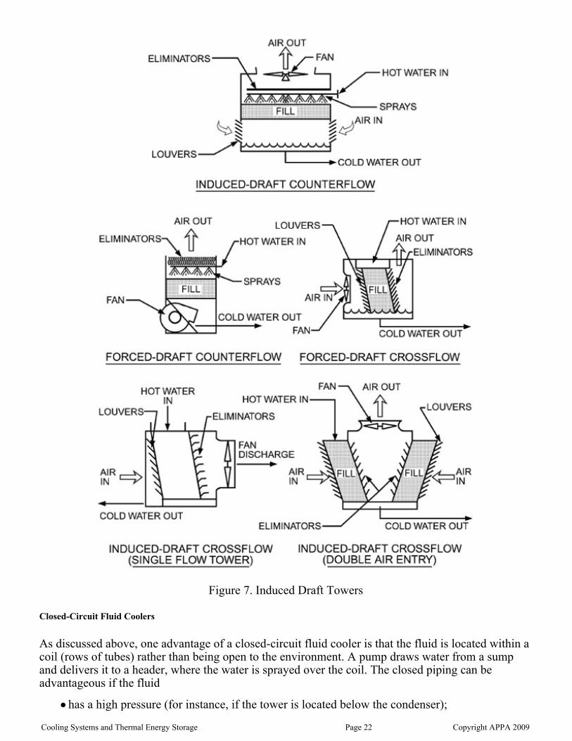
Figure 7. Induced Draft Towers
Closed-Circuit Fluid Coolers
As discussed above, one advantage of a closed-circuit fluid cooler is that the fluid is located within acoil (rows of tubes) rather than being open to the environment. A pump draws water from a sumpand delivers it to a header, where the water is sprayed over the coil. The closed piping can beadvantageous if the fluid
has a high pressure (for instance, if the tower is located below the condenser);
Cooling Systems and Thermal Energy Storage Page 22 Copyright APPA 2009

is mixed with fluids from other systems (like the chilled water); orhas the primary pump located remotely from the tower.
With proper initial chemical treatment, the fluid (usually some form of glycol solution) does not foulthe condenser tubes, so chiller maintenance is reduced and energy efficiency is always at peak.Because of the additional heat exchange process, for the same capacity as an open tower, theclosed-circuit fluid cooler is physically much larger and significantly more expensive thanconventional open towers.
Application Issues
Siting and Recirculation
When the saturated air leaving the cooling tower is drawn back into the intake of the tower, therecirculation that occurs degrades the performance of the tower. Wind forces create a low-pressurezone on the downwind side of the tower that causes this phenomenon. Wind forces on the lee side ofthe building can also create downward air movement. When cooling towers are located in such away that the discharge from one tower is directed into the intake of an adjacent tower, recirculationcan also occur. Recirculation is a greater problem when cooling towers are confined within pits, orhave screen walls surrounding them. If the tower is sited in a pit or well, it is essential that the towermanufacturer be consulted to determine the proper location of the outlet and minimum clearances forthe air intake. As previously discussed the potential for recirculation is greater with forced-drafttowers than with induced-draft towers.
The Cooling Tower Institute recommends that recirculation effects be accounted for in the selectionof the tower. Its tests show that as much as 8 percent of the discharge air could be recirculated backinto the intake and that the worst conditions occur with winds of 8 to 10 miles per hour. Whererecirculation is a concern, a rule of thumb is that the EWB temperature used to select the towershould be increased by 1°F above the ambient temperature to account for recirculation effects.
Capacity Control
Like most air conditioning equipment, cooling towers are selected to perform at maximum peakcapacity at design weather conditions. Of course, most of the time they operate at less than peakcapacity. A number of methods are used to control the temperature of the water leaving the coolingtower, including the following:
On/Off: Cycling fans is a viable method but leads to increased wear on belts and drives (ifused) and can lead to premature motor failure. This is the least favorable method of controllingtemperature.Two-Speed Motors: Multiple wound motors or reduced voltage starters can be used to changethe speed of the fan for capacity control. This method is cost-effective and well proven.Because of basic fan laws, there are significant energy savings when the fans are run at lowspeed. One pitfall with two-speed fans is that when switching from high to low speed, the fanrpm must reduce to below low speed before the low-speed motor is energized. Strategies foroptimum operation of two-speed fans will be discussed in the next chapter.Pony Motors: This is another version of the two-speed approach. A second, smaller motor isbelted to the fan shaft. For low-speed operation, the larger motor is deenergized and thesmaller motor energized for a lower speed. This is a cost-effective and energy-efficientapproach. Again, when going from high speed to low speed, the fan must slow downsufficiently before the low-speed motor is energized.Variable-Speed Drive (VSD): Adjustable frequency drives can be added to the motors forspeed control. This method provides the best temperature control performance and is the mostenergy-efficient method of control. It may also be the most expensive. A life cycle cost
Cooling Systems and Thermal Energy Storage Page 23 Copyright APPA 2009

energy-efficient method of control. It may also be the most expensive. A life cycle costjustification should be done before selecting this method. When comparing VSDs with otherapproaches, carefully factor the cost of control points for each alternative into the analysis.One pitfall to avoid with VSDs running the fans at the “critical” speeds. These are speeds thatform resonance frequency vibrations and can severely damage the fans. Consult with coolingtower manufacturers before using VSDs.Modulating Discharge Dampers: Used exclusively with centrifugal fans, discharge dampersbuilt into the fan scroll can be modulated for capacity control. This is a cost-effective way toaccomplish close temperature control. Although it does save energy by “riding the fan curve,”other methods of capacity control may provide better energy savings.
In general, VSDs are recommended over the other options for the following reasons:
Lower first costTighter temperature controlLower operating costsReduced noiseControl information available from the VSD
Chemical Treatment and Cleaning
Cooling towers are notorious for requiring high maintenance. The use of cooling towers has beenlinked with the outbreak of legionellosis (Legionnaires’ disease). Unfortunately, cooling towers arevery good air scrubbers. A 200-ton open cooling tower can remove 600 pounds of particulate matterin 100 hours of operation. Because they are open to the atmosphere, the water is oxygen-saturated,which can cause corrosion in the tower and associated piping. Towers evaporate water, leavingbehind calcium carbonate (hardness) that can precipitate out on the tubes of the condensers anddecrease heat transfer and energy efficiency.
Towers must be cleaned and inspected regularly. Well-maintained and regularly cleaned coolingtowers have generally not been associated with outbreaks of legionellosis. It is best to contract witha cooling tower chemical treatment specialist. The following are some strategies to consider in agood chemical treatment program:
Blowdown: To control dissolved solids a portion of the flow of the tower should bedischarged into the sewer. A rule of thumb is that for a buildup of no more than 2 to 4concentrations of hardness, the blowdown rate should be about 0.5 to 1.0 percent of the totalflow rate.Scale Prevention: Control of the pH (acid levels) is extremely important. Acids, inorganicphosphates, or similar compounds are commonly used to control pH.Corrosion Control: Corrosion can be caused by high oxygen content, carbon dioxide (carbonicacid), low pH, or high dissolved solids. Blowdown is the most practical solution.Biological Growth: Slime and algae are handled with shock treatments of chlorine or chlorinecompounds. It is best to alternate between two different compounds so that organisms do notdevelop a tolerance to the chemicals.Foam and Scum: Usually caused by excess organic material. Cleaning the machine is the bestremedy.
New technologies are being introduced for the treatment and cleaning of cooling towers. Onetreatment is the introduction of ozone (O3) into the cooling water. Ozone is a very aggressiveoxidizer and when properly applied can be effective at reducing biological growth. One pitfall in theuse of ozone is that if left unchecked, large concentrations of ozone will cause runaway corrosion ofpiping and cooling tower basins. Ultraviolet (UV) lights have also been used to control biologicalgrowth when coupled with suitable filtration systems. Another promising nonchemical method
Cooling Systems and Thermal Energy Storage Page 24 Copyright APPA 2009
employs pulsed electromagnetism to remove dissolved solids and inhibit biological growth.
Performance of Cooling Towers
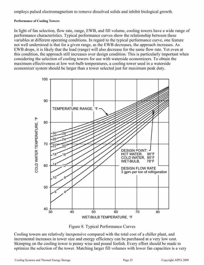
In light of fan selection, flow rate, range, EWB, and fill volume, cooling towers have a wide range ofperformance characteristics. Typical performance curves show the relationship between thesevariables at different operating conditions. In regard to the typical performance curve, one featurenot well understood is that for a given range, as the EWB decreases, the approach increases. AsEWB drops, it is likely that the load (range) will also decrease for the same flow rate. Yet even atthis condition, the approach still increases over design condition. This is particularly important whenconsidering the selection of cooling towers for use with waterside economizers. To obtain themaximum effectiveness at low wet-bulb temperatures, a cooling tower used in a watersideeconomizer system should be larger than a tower selected just for maximum peak duty.
Figure 8. Typical Performance Curves
Cooling towers are relatively inexpensive compared with the total cost of a chiller plant, andincremental increases in tower size and energy efficiency can be purchased at a very low cost.Skimping on the cooling tower is penny wise and pound foolish. Every effort should be made tooptimize the selection of the tower. Matching larger fill volumes with lower fan capacities is a verygood investment.
Cooling Systems and Thermal Energy Storage Page 25 Copyright APPA 2009

good investment.
For a given design of a cooling tower, the manufacturer will normally attribute a maximum andminimum flow condition to the tower. The maximum flow is usually based on the capacity of thewater distribution system within the tower to adequately distribute the water over the fill. Too muchflow will overflow the tower distribution pans and create a situation in which the tower does not getadequate mixing of air and water to perform properly. At minimum flow the water may notdistribute evenly across the entire fill. This creates voids where there is no water in the fill. Whenthis happens the airstream will tend to travel through the fill area with no water and will not mixproperly with the fill area that has the water. This creates a significant decrease in the expectedperformance of the tower. Another drawback to operating under the minimum flow is that at theboundary where the water and high-velocity air meet, a condition is created where the water iscarried up through the fans and the tower “spits” water. Prolonged operation below the minimumwater flow can also cause scaling to occur on the fill where the water is missing.
In general, propeller fan cooling towers use half the energy of centrifugal fan towers for the sameduty and have a lower first cost. Exceptions are provided for installations with external staticpressure such as ducted inlet or discharge or the need for sound traps. If acoustical criteria areimportant, the reader is encouraged to investigate low-noise draw-through towers with propellerfans. These towers have the following features:
Heavier gauge of metal on the fansSlower fan speedsLow-pressure sound traps
These low-noise propeller fan towers are generally as quiet as a centrifugal fan tower without soundtraps, are less expensive, and have better energy performance.
Cooling Tower Accessories and Options
The following is a list of accessories and options that should be considered when purchasing acooling tower:
Filters: Sidestream filters include either sand filters or centrifugal separators. Do not useswimming pool sand filters for cooling towers. Sidestream filters generally circulate about 10percent of the system flow.Fan breaks or stops: These are devices that prevent the fan from rotating backward. Considerthese options if multiple cells are used and backflow airflow through a down fan may cause itto rotate in reverse. Starting a reverse-rotating fan can damage the motor. As conditions forreverse rotation seldom occur, these options are rarely applied.Vibration switch: This stops the fan if vibration exceeds a certain limit. It could preventcatastrophic failure of the fan. Codes in some areas require the installation of a vibrationswitch.Ladders and access platforms: Any area where maintenance personnel need to inspect, repair,or replace equipment should have adequate access. Without easy access, towers may not bemaintained to the degree that protects the chiller plant investment.Vortex breaking inlet screens: These prevent air from being drawn into the pump suction.They are essential accessories.Sump heaters may be required in cooler climates where draining of the tower is not an optionduring periods when there is a chance of freezing conditions.
Cooling Systems and Thermal Energy Storage Page 26 Copyright APPA 2009

Auxiliary Equipment
Auxiliary Equipment
Chemical Feed Systems
Chiller plants have two water systems that require conditioning and treatment. As outlined above,condenser water systems have equipment to monitor the quality of the water, to add chemicals, tomaintain desired levels of dissolved solids, and to add makeup water to offset evaporation, leakage,and blowdown. The chilled water system has pot feeders for adding corrosion inhibitors to thesystem and a coupon station for measuring the effectiveness of the inhibitor.
Sidestream Filters and Separators
A filtering system is necessary to remove solids such as dirt, rust, and debris from the chilled water.Individual strainers and filters are required on sensitive equipment that may be plugged bycontaminants in the system.
Sidestream filters can be installed within the chiller plant to continually filter a small portion of thetotal flow, as it is generally not feasible to install a filter system with sufficient capacity toaccommodate the entire chilled water flow.
Chilled Water Makeup
Chilled water makeup is needed to replace losses from leaks and maintenance activity. Makeup canoccur by pumping water from a storage tank or by using a regulator and backflow preventer to takewater directly from the domestic water system. Overall system pressure is regulated by this makeup.It is desirable to have the chilled water system pressure below the domestic water pressure to preventpotential contamination of the domestic water system if a cross-connection inadvertently occurs. Forconvenience and simplicity, the number of potential makeup locations should be kept to a minimum.Makeup should be measured by using a conventional water meter.
Expansion Tank
Expansion tanks are required on the chilled water system to accommodate the expansion andcontraction associated with any thermal liquid system and to provide a point of constant pressure inthe system. The expansion tank should be built with bladders to isolate the air from the liquid.
Automatic Air Release Vents
Air becomes trapped within the chilled water system whenever equipment or piping is restored toservice after the chilled water is drained from the system. Entrapped air can adversely affect theoperation of the chilled water system by significantly reducing chilled water circulation and heattransfer. Difficulty due to the compressibility of air can occur when the system pressure on aparticular segment of the system is relieved for maintenance activities. Automatic air release valvesshould be added to high points within the system where air can be trapped, including chillers, tanks,piping, and terminal equipment.
Controls and Instrumentation
Operating and safety controls are furnished as part of the chiller package. Instrumentation such aspressure gauges, thermometers, and flow measuring devices must be specified where they arerequired or desired. Pressure gauges should be provided on the inlet and outlet of all vessels, pumps,and strainers. Thermometers with wells should be provided at the inlet and outlet of all equipmentwhere a change in temperature will take place.
Cooling Systems and Thermal Energy Storage Page 27 Copyright APPA 2009

Metering
Chilled water systems should have sufficient metering to measure the system performance as well asindividual components. Metering should measure the energy inputs and energy outputs of thechilled water system. This metering is necessary to determine system optimization and to analyzecapacity-related issues.
Flow-measuring devices should be installed in chilled water, condenser water, steam, and makeupwater lines to the cooling tower. The flow meters must have sufficient straight runs of pipe upstreamand downstream of the meters to ensure meter accuracy. Flow-sensing elements can be of theultrasonic, magnetic, vortex shedding, full-pipe-size positive displacement, full-pipe-size turbine,insertion turbine, insertion differential pressure, orifice plate, or venturi style.
Modern chilled water energy meters consist of a wide variety of flow-sensing elements, severaltemperature-sensing devices, and an electronic processor that receives input to calculate and totalizethe energy. Programmable electronic devices can communicate with even more sophisticatedcentrally located computer systems.
The accuracy of chilled water meters is a function of the turndown (range of the sensing), theprecision of the flow-measuring element, and the accuracy of the temperature-sensing device. Caremust be taken to clearly understand the implications of the specifications on the accuracy of theenergy meter. The greatest potential energy calculation inaccuracy occurs with thetemperature-sensing devices. For example, a temperature-sensing device with a range of 0° to 200°F,with an accuracy of 1 percent of the full-scale range, will have an output accuracy of ±2°F. In achilled water system with a design differential of 10°F, the accuracy of the system would be ±20percent.
For any meter to function within its accuracy range, it must be routinely calibrated and accuraterecords maintained on the calibration procedure.
Insulation
Thermal insulation with a vapor barrier is required on chiller evaporators, refrigerant suction lines,compressors, expansion tanks, chilled water supply and return lines in the plant, and any otherequipment connected to the chilled water system that is subject to sweating. The vapor barriershould be sealed at regular intervals along the pipe so that in case of a leak or damaged vapor seal,the travel of the moisture will be limited.
Chillers, heat exchangers, and tanks should be insulated with material such as fiberglass, cellularglass, or closed-cell foam rubber sheet insulation. Acoustic insulation may be needed to reduce thenoise level on certain items in the central plant, such as chiller condensers and compressor dischargepiping. Removable heads on chillers and heat exchangers should be insulated with covers that canbe easily removed to allow access for inspection, cleaning, and dismantling. Insulation material thatis not subject to damage by moisture is preferred.
All low-temperature insulated piping within the chiller plant, buildings, and vaults should haveinsulation at each hanger, support, and anchor. The insulation should also be protected with shieldsof galvanized metal extending not less than 4 inches on either side of the support bearing area, and itshould cover at least half of the pipe circumference. Pre-insulated steel pipe is a popular materialand minimizes field insulation labor.
Soil temperatures at burial depths will determine the magnitude of energy loss to the soil withuninsulated direct-buried pipe as well as various insulation materials. An energy evaluation isneeded at each central chilled water site to determine what, if any, insulation is needed. If it isdetermined that it is economical to install insulated pipe, then pre-insulated pipe is available in
Cooling Systems and Thermal Energy Storage Page 28 Copyright APPA 2009

various pipe materials.
System Design Considerations
The central chilled water system criteria are a set of requirements that provide guidelines for thedesign and operation of all equipment as well as the thermal systems. The central chiller plantrepresents only part of the overall chilled water system, and the system criteria should not be limitedto this facility alone. Other equally important parts include the distribution system and buildingsystems. A single philosophy must exist for the design and operation of the entire chilled watersystem if the individual parts are to function correctly and economically. Operating problems anddifficulties in many central cooling systems can be traced to a single common cause: incompatibilityamong the chilling equipment, piping systems, and terminal loads.
Prior to deciding on the piping and pumping configurations, a thorough study of the proposed orexisting system must be completed. The four fundamental steps are as follows:
A complete hydraulic analysis is a necessity to determine the system performance.Deficiencies and strengths of the system can be identified with such an analysis. Without thiscomprehensive evaluation, many systems have been installed with serious deficiencies. Significant rework of previously installed components, with the attendant significantreplacement and operating costs, has occurred in many institutions as a result of failure toperform this step. This is one of the most important steps to be completed before proceedingwith any capital investment.
1.
Component compatibility can be analyzed after completing the hydraulic analysis. Thehydraulic analysis addresses the volumetric component of the chilled water, but it does notinclude the energy component of the chilled water. Therefore, an energy analysis must becompleted.
2.
Any system analysis should take into account the installed cost along with full consideration ofthe operating cost over the life of the system. The temperature differential between the chilledwater supply and return should be maximized, which will minimize the volume of chilledwater to meet the energy capacity of the chilled water. A reduction in chilled water volumereduces the pump energy required to move the water and also reduces the pressure lossrequired to transport the chilled water throughout the system. Therefore, increasing thetemperature differential between the chilled water supply and return has a dual effect onreducing the pumping energy by reducing the volume and pressure loss within the system. Theenergy capacity of a given distribution main can be increased simply by increasing thetemperature differential between the supply and return main.
3.
After the previously listed items have been completed, the pumping methods and pipingconfiguration should be examined. Caution should be exercised not to attempt to correctcomponent incompatibility by altering pumping methods or piping configuration, as this canplague the performance of the entire chilled water system for years to come. The piping andpumping configurations should result in the least complicated and most energy-efficientsystem. The number and sophistication of controls and pumps associated with the systemshould be kept to a minimum. If the system cannot be easily explained to and understood by anontechnical person, then errors have probably been made in arriving at the optimal systemconfiguration.
4.
There are three commonly used piping and pumping systems in most chilled water systems: primary,secondary, and tertiary systems. There are numerous permutations of equipment layout within thesethree types.
A primary loop involves pumping chilled water from pumps that are in a central cooling plant chiller
Cooling Systems and Thermal Energy Storage Page 29 Copyright APPA 2009

A primary loop involves pumping chilled water from pumps that are in a central cooling plant chillerloop. These pumps circulate the chilled water through the chiller, and can also circulate waterthrough the supply distribution piping, building supply piping, terminal units, building returnpiping, and return distribution piping to return the chilled water to the pump suction.
A secondary loop has a piping loop separate from the primary loop. Each loop has its own pumpingloop, and the two pumping loops are generally connected with a common hydraulic decouplingbypass line. Individual loops can occur within the chiller plant, distribution, or building systems.
A tertiary loop has three individual piping loops. It adds one more pumping loop to the secondarysystem described above. This would typically occur at building connections but is not recommendedfor chilled water systems.
Chillers can be connected to individually dedicated cooling towers or into a common header. Thisphysical layout should be fully analyzed to ensure equipment compatibility. Chiller and towerequalization must be met so that capacity or efficiency is not compromised throughout the range ofvarying loads.
Pumping and Piping Systems
Pumping costs should be minimized to keep the overall efficiency of the chilled water system ashigh as possible. Therefore, flow rates to individual components and bypasses around equipmentshould be kept to a minimum. Typically, chilled water pumping horsepower should beapproximately 0.05 BHP per ton of chilled water capacity. Delivered pressure should be only highenough to meet the circulation needs of the system. Excessive pressure causes control valves tothrottle the flow, which creates an energy loss in the system. To prevent overpumping,variable-frequency-drive pumps should be installed in most situations to minimize pumping energyfor the system. Pumping energy is transferred into the chilled water, which ends up adding to thecooling load of the system.
Ideally, the pressure required to circulate the chilled water from the chiller through the buildings andthen back to the chiller should normally be less than 40 psig. If greater pressure drops occur, thesystem should be analyzed to locate inappropriately sized equipment and piping.
Chiller Plant
Decisions that are made in selecting and arranging equipment will affect system operation for manyyears. Therefore, care should be taken to accurately analyze all aspects of the decision-makingprocess. The design requires an investigation of all details and coordination of the many ideas andrequirements into an optimum end product or facility. A good design will make provisions for futureexpansion and anticipate the flexibility needed to take advantage of new ideas, equipment, andtechnology. A design that considers only present needs and technologies probably will not make fora cost-effective facility in the future.
During the development of the design for a central chiller plant, the primary concern is the process,equipment layout, access for maintenance, and future expansions. A plant building should not bedesigned until the layout of the equipment and all support systems is well established. The buildingis an enclosure to protect the chilled water equipment and should be a functional part of the overallcooling facility, not the dominant factor. The process should not be changed to accommodate thesize of the building or restrictions imposed by the building. The same is true of the site or locationfor the plant; if major equipment layout changes are required to adapt a plant to a particular location,then perhaps the site is wrong.
System reliability is a product of component quality and durability in conjunction with thepreventive maintenance programs. Redundant equipment is sometimes employed for seasonal load
Cooling Systems and Thermal Energy Storage Page 30 Copyright APPA 2009

variation and reliability, and where critical environments justify the additional capital andmaintenance expenditure. Certain electricity demand rates can also justify adding particular systemcomponents to avert expensive electrical penalties if equipment downtime occurs.
The system criteria are tools for selecting equipment and developing operating procedures. Thecriteria must be established when the design of the central chilling plant is started and then mustcreate a compatible design among the plant, the distribution system, and the buildings served. Therequirements established by the system criteria must be considered each time the plant is expandedor a new building or facility is added. The combined characteristics of all the building airsidesystems are one of the major factors in developing the system criteria. These same characteristicswill be a determinant of plant economics. Airside systems must not be operated far from their designconditions if economical, high-quality air conditioning is to be provided.
Designing and constructing a central chilling system are major undertakings. System reliability,performance, and serviceability are all critical elements in the design process. Initial decisions willhave significant implications for plant size. It is obvious that an undersized plant will havedetrimental end results. Oversizing a plant may not have the obvious disadvantage of undersizing,but it can cause the overall project to be burdened with excessive capital expenditures and result inpoor part-load energy efficiency. Careful thought should be given to sizing decisions early in thedesign process.
Pumping arrangements for water circuits within a central chilled water plant normally fall into thefollowing categories:
A unitary arrangement, in which a single pump is dedicated to a specific chiller (Figure 9).This arrangement may be found in both primary and variable primary flow pumping systems,as well as in condenser water pumping systems.
Figure 9. Unitary Arrangement
A primary/secondary pumping system, in which the hydraulic head requirements for the chillerand in-plant piping are furnished by pumps dedicated to specific chillers, and the distributionsystem hydraulic head requirements are furnished by a separate decoupled pump circuit(Figure 10).
Cooling Systems and Thermal Energy Storage Page 31 Copyright APPA 2009

Figure 10. Primary/Secondary Pumping System
A headered arrangement for chilled water pumps, in which a number of pumps discharge intoa common header serving a bank of chillers (Figure 11). This arrangement may be found inboth primary and variable primary flow pumping systems. This type of arrangement may alsobe found in condenser water pumping systems.
Figure 11. Headered System
Variable primary flow pumping systems have become more popular as chiller manufacturers areallowing the chilled water flow to vary through the chiller evaporator. This allows the chillers towork at higher load factors as a result of the varying chilled water temperature differentials, whichcan vary depending on the season. A bypass is typically provided to ensure the chiller does notoperate below the minimum allowable chilled water flow rate. The other advantage of variableprimary flow systems is that fewer pumps are required, resulting in less space needed within thecentral plant.
Building Interconnection
Building connection analyses are important for the entire chilled water system. Tertiary loops shouldbe avoided at the building connections. This method artificially attempts to increase the buildingtemperature differential by recirculating the chilled water return from the building and can havedisastrous results. Building humidity control and system hydraulics can be hindered to the point ofmaking the system inoperable.
Low return temperature is primarily the result of improperly selected coils or coil control valves.
Cooling Systems and Thermal Energy Storage Page 32 Copyright APPA 2009

Coils should be designed for the maximum chilled water temperature differential. The waterperformance of a cooling coil is based on the mean temperature differential between the supply andreturn water temperature at selection. If the chilled water supply temperature increases, the chilledwater return temperature will decrease to maintain the same mean temperature. This requires greatattention during the coil acquisition and installation process to make sure that the coil performancecan maximize the chilled water temperature differential and still meet the building coolingrequirements.
Hydraulic interfaces between central systems and building systems can vary widely in controlstrategies but will generally be described by one of the following hydraulic arrangements:
A straight primary interface, in which the necessary building circulating head is supplied bythe central system pumps (Figure 12).
Figure 12. Primary Arrangement
A variable-speed booster pump building interface, in which central plant pumps providebuilding circulation when adequate head is available and building chilled water pumps provideadditional differential pressure when central system head is not adequate to meet loadrequirements (Figure 13). A differential pressure sensor is required at the hydraulically remotelocation in the building to control the booster pump.
Figure 13. Variable-Speed Booster Pump Interface
System Performance
Cooling Systems and Thermal Energy Storage Page 33 Copyright APPA 2009

Diversity Factor
Buildings connected to a central system will not experience peak load at the same time. Thisrelationship between the sum of the peak loads for individual buildings and the actual aggregatecentral system peak load is known as the diversity factor. For example, dormitories may havereduced loads during the day and peak loads in the evening; libraries and laboratories can havesubstantial loads during the day that may extend into the evening hours; classrooms andadministrative areas usually have peak demands during the day only; and auditoriums and athleticfacilities have peak demands associated with specific activities. It is difficult to predict diversity withnew systems, whereas with adequate metering, information on existing buildings that are beingconsidered for connection onto a central system can be determined with reasonable accuracy.
Central plants can be designed for a capacity of something less than the sum of the individualbuildings. The magnitude of this reduction is affected by the type and number of buildingconnections. This phenomenon should not be overlooked, as this is an opportunity to save capitalwhen installing new equipment. Typical university campus cooling diversity factors can range from0.5 to 0.7. If a plant can be sized to operate near design conditions, overall plant efficiency will beoptimized. Oversizing the chillers will lead to poor part-load energy performance.
Load Factor
The ratio of the total cooling energy produced over a year compared with the total potentialgenerated by the installed chilling equipment is defined as the load factor. Load factors typicallyrange from 9 percent to more than 25 percent. This ratio is highly dependent on the climate and thetype of loads that are connected to the system. Comparisons can be made between similarinstallations to arrive at some guidelines for evaluation of existing and planned systems.
Even with a load factor of 25 percent, it is evident that chilled water systems have the capability ofdelivering significantly more chilled water than is actually generated. Because most load on thesystems is comfort cooling, additional comfort load cannot be added without affecting the peakdemand on the system. Adding process loads that are present year-round increases the load factorwithout substantially affecting the peak demand. These process loads take advantage of the investedcapital.
Load Duration Curve
Load duration curves are used to graphically show the central plant installed capacity, the loaddemands, and the time duration per year for the system load operated at each level. This is illustratedin Figure 15.
Cooling Systems and Thermal Energy Storage Page 34 Copyright APPA 2009

Figure 15. Load Duration Curve
The load duration curve can be helpful in determining equipment sizing. The total cooling producedis equal to the area under the curve. The area under the horizontal line, representing the plantinstalled capacity, equals the total potential capacity for the plant over a year. The ratio betweenthese two areas is equal to the plant load factor.
Load duration curves can also show the amount of time the system operated at a specific capacity.The equivalent full-load hours can be determined by taking the area underneath the operating curve(total energy produced) and dividing it by the total installed plant capacity.
Horizontal lines can be drawn to indicate the incremental available capacity as individual chillersare operated. Machine sequencing can be illustrated to show when specific chillers will be operated.It can be seen that, as additional chillers are needed to operate, hourly utilization of these chillersbegins to diminish. This will coincide with operating the chillers at their highest efficiency, asindividual chillers operate at the highest efficiency when operated at rated capacity. Multiple unitswithin a facility allow chiller generation capacity to match overall system needs more closely bysequencing the chillers to match the load profile. The downside to having multiple chillers is that thecost to purchase and install many small machines is significantly higher than it is for fewer largermachines.
The magnitude of the load duration curve can exceed the plant installed capacity curve on systemsthat do not have the capacity to meet the peak demand on the system. This can be a temporary statecaused by recent additions or a condition that is not intended to be addressed based on an economicevaluation versus the duration of peak. Options may exist to shed noncritical loads a few hours peryear. Other systems may allow the entire system to uniformly shed load by allowing the chillerdischarge temperature to rise after rated capacity is achieved.
Thermal storage is another element that can be included in the load duration curve. Thermal storagebenefits can be illustrated to show how load requirements can be met when exceeding the installed
Cooling Systems and Thermal Energy Storage Page 35 Copyright APPA 2009

capacity of the chiller plant. The total generated chilled water will be the same with thermal storageas when using chiller equipment. The peak of the generation curve is removed and added back intothe area under the curve.
Building Performance
The peak chilled water demand for specific building types can be calculated by applying industrystandards for gross square footage per ton. The demand for a particular building can be calculated bymultiplying the building square footage by this factor.
For central plant cooling systems, standard ranges from 400 to 700 sq. ft. per ton. The lower tonnagerange generally applies to buildings that have low air exchange rates and are well insulated. Theupper range applies to buildings that have high air exchange rates (e.g., laboratories and hospitals) inextreme cooling climates. Individual buildings have larger performance factors if they are going tobe served by localized equipment, because central cooling systems experience load diversity.
Total, Firm, and Reserve Capacity
Central chilling plants usually have multiple water chilling units, cooling towers, pumps, boilers,and associated equipment. From time to time, each item of equipment will be out of service forcleaning, maintenance, or repairs. Cleaning and maintenance usually require a scheduled outage fora relatively short period. Planned extended outages are normally scheduled during periods ofminimum cooling loads. On the other hand, required repairs to major equipment may not bescheduled.
The total capacity of a central plant is the sum of the capacities for all units installed. However, thefirm capacity is the sum of all units installed minus the capacity of the largest unit. This assumesthat all units are potentially operational and can produce their rated capacity; otherwise only theunits that are actually operational at the time should be used to determine plant capacity.
The firm capacity is the maximum capacity that the plant can be expected to produce on acontinuous basis. As buildings and new loads are added to the system, reserve capacity is used andexpansion of the plant will eventually be required. Reserve capacity is any plant tonnage above themaximum system demand, up to the firm capacity.
Some extra capacity can be attributed to reserve and future capacity. When multiple machines areused to achieve the needed capacity, reserve capacity is already built into the system in the event thatone machine is out of service. Although it is good to design a plant with some excess capacity,extremes of excess capacity will hinder the project economics and return on investment.
Operation and Maintenance
A central chiller plant represents a large capital and operating cost. To determine optimalperformance of a central chilled water system, the full- and part-load performance data for eachchiller should be used to determine which chiller or combination of chillers will deliver cooling inthe most efficient manner. Maintaining the equipment in good working order with proper controlsand adjustments for optimum energy efficiency takes on great importance. In the followingparagraphs, certain operations and maintenance considerations unique to central chiller plants arediscussed.
Maintenance
Each chiller has a manufacturer-recommended charge of refrigerant. These recommendations are
Cooling Systems and Thermal Energy Storage Page 36 Copyright APPA 2009

based on maximum summertime cooling. The theoretical charge for other operating conditions willbe different. Operating personnel from various parts of the country have reported significant energysavings by reducing the charge during periods of low load operation.
Chiller condenser and evaporator heat exchanger cleanliness should be monitored throughout thecooling season by calculating the fouling factor to determine when equipment must be cleaned.Automatic online tube-cleaning systems for chiller condensers are proven energy conservationmethods. They are designed to keep the inside (water-side) surface of the tubes free of any depositsthat would interfere with the heat transfer process. Two types of online tube cleaners are available: abrush system and a sponge rubber ball system. In the first type, the flow of water through thecondenser is reversed and causes a small brush to be pushed through each tube. A plastic cage at theend of each tube holds the brush until the next cleaning cycle. The second type injects sponge rubberballs into the water entering the condenser. They pass through the tubes and are then collected by ascreen located in the leaving water. From the collection screen, the balls are routed to a circulatingpump that reinjects them into the entering water.
Energy Audit
Equipment in the plant should be checked from time to time to be sure that it is operating efficiently.This is vitally important on the larger items of equipment, such as chillers, that use the largestportion of energy. A unit that has scaled-up heat exchangers, improper refrigerant charge, bad seals,or worn parts or is dirty will consume more energy than a similar unit that is well maintained. Theenergy input divided by the output (kilowatts per ton or pounds of steam per ton) is a convenientyardstick of performance. If the values begin to change, the cause should be determined andcorrected. A heat balance should periodically be made on all major equipment.
The importance of keeping records on equipment is well accepted. For many years the history ofequipment performance was limited to logs that were filled out by the operators, along with utilityreceipts. Many plants currently have computer-based data-logging systems. These systems can logall data monitored at any time interval and can provide operating profiles on an hourly, daily,weekly, monthly, or yearly basis. They can monitor performance continuously and sound an alarm ifallowable limits are exceeded.
Energy Conservation and Optimization
Compressor Power Reduction
Compressor power consumption for a chiller increases as the compressor head (pumping energy)increases. Compressor head is reduced by increasing the chilled water temperature and/or loweringthe condenser water temperature. A 1°F increase in chilled water or a 1°F decrease in condenserwater will reduce the required compressor consumption by 1.5 to 2.0 percent. Temperatureconstraints and the economics of operating under various scenarios should be investigated todetermine the optimal operating temperatures under a given service condition.
Free Cooling
Many central cooling systems operate year-round. During periods of cool weather, savings can berealized by using the cooling tower condenser water to cool, rather than operating chillingequipment. A heat exchange device is required to separate the condenser water from the chilledwater. Operating in this mode is called free cooling. However, the chilled water is not free, becauseauxiliary equipment still must be operated. Free cooling can occur when the outside ambient airconditions are cool, which is typically at times other than the normal comfort cooling season.
Discharge chilled water temperature to the chilled water system is usually dependent on the outside
Cooling Systems and Thermal Energy Storage Page 37 Copyright APPA 2009
air conditions unless controls are installed to mix the discharge from operable chillers with thechilled water generated from free cooling. Chilled water supply temperatures therefore increase withincreasing outside air temperatures and humidity. The limitation of chilled water temperaturefluctuations is dependent on the type of loads that are connected to the system. Process coolingrequirements usually can tolerate elevated temperatures. Comfort cooling at locations where there ishigh internal heat gain within the occupied space typically requires much cooler water than processcooling loads. If the comfort-cooling requirement outside of the normal cooling season is small incomparison to process cooling, then the installation of small localized cooling systems to meet theseneeds may be justified. Localized cooling systems can significantly extend the free cooling season.Capital expenditures for installation of such equipment may be justified if large chilling equipmentcan be turned off for extended periods. In northern climates it may be possible to shut off chillingequipment for as long as six months a year by utilizing free cooling.
Cooling tower freeze protection, through the application of sump heaters and/or heat tracing, mustbe considered. Options should include circulating water only in the tower basin or cycling towerfans when the outside air temperatures are well below freezing. It is desirable to run the coolingtower supply water temperature as high as possible when the outside air temperatures are belowfreezing.
Thermal Storage
Thermal storage can be an effective means of conserving energy under the right circumstances andconditions. It is necessary to evaluate the economics of this option. Some utility companies areparticipating in the funding of thermal storage projects and are offering reduced rates for night oroff-peak consumption. Usually both of these are needed to make the project viable. Thermal storagesystems tend to be large, especially if they are storing chilled water. An ice storage system requiresless space for storage, but must have additional cooling capacity to produce the ice.
Load Shedding
System demand for chilled water may exceed the available or economical capacity of the chillingequipment. Regardless of whether the installed capacity has been exceeded or electric demandcharges make it desirable to limit the load on the chilled water systems, the methods to shed loadwill probably be the same. Loads can be selectively reduced, or the inherent characteristics ofchilled water systems can be changed to allow the load shedding to occur somewhat uniformlythroughout the system.
Selective load reduction can be as basic as shutting off equipment or as sophisticated as an energymanagement system that has control over all chilled water system components. Energy managementsystems can reschedule activities and change set points on individual air handlers to decrease loadfor a limited period of time to remove peaks on the system.
Increasing the chilled water supply temperature to the terminal units results in a uniform loadreduction across the entire system. This normally will not be readily apparent to building occupantsunless significant load reductions are needed or existing comfort cooling equipment has marginalcapacity before the load shedding occurs. The chilled water temperature can be increasedintentionally by increasing the chiller set point. Another option is to load the chillers to achievemaximum capacity, at which time any further attempts to increase load will result in a decrease inthe discharge chilled water temperature.
The anticipated need should normally be recognized well in advance of the actual event. All usersshould have a full understanding of what to expect during a load-shedding situation. Feedbackshould be provided by the end-user so that undesirable outcomes do not result from this process.
Water Treatment
Cooling Systems and Thermal Energy Storage Page 38 Copyright APPA 2009

Water Treatment
An effective water treatment program is necessary for the continued efficient operation of a centralchilled water plant. Water treatment reduces fouling of the chiller heat exchangers and systemcorrosion.
Water treatment programs for any central chiller plant should be formulated by water treatmentprofessionals. Consulting professionals are available to oversee the treatment program and tomonitor its efficiencies through laboratory analysis. Vendors can provide complete turnkey systemsthat address all aspects of water treatment, from the control-and-feed system to corrosion monitoringand chemical supplies.
Cooling Tower
The condensing water system is an open circulating system and is subject to problems of scale,corrosion, slime, and algae. As water is evaporated in the cooling tower, the dissolved solids will beconcentrated in the remaining water. If the concentration is allowed to build up, the solubility ofvarious salts will be exceeded, and scale will form on the hotter surfaces, such as condenser tubes.This can be controlled by blowdown or bleed-off in some cases, but it may be necessary to feedsulfuric acid for pH control, in addition to the blowdown, if the water is extremely hard and high inalkalinity.
Open recirculating cooling water systems provide optimum conditions for microbial growth, andthese microorganisms can adversely affect the efficiencies of the operation by sheer numbers,metabolic waste products generated, or deposits created. Microbiological treatment programs useoxidizing and nonoxidizing biocides, such as chlorine, hypochlorites, organic chlorine donors, orbromine compounds. Chlorine is effective but must be used carefully, because excessive chlorinewill increase corrosion and adversely affect tower wood. Some plants have tried to reduce theirexpenses by cutting back or eliminating the chemical for water treatment and have causedirreversible damage to their systems. Occasionally a new nonchemical device appears on the marketwith claims for scale and corrosion control in cooling and boiler systems. These nonchemicaldevices may be based on mechanical, electrical, magnetic, electrostatic, or ultrasonic principles. If anonchemical water conditioning device is being considered, it should be thoroughly investigated.Several successful applications on similar facilities should be inspected and evaluated.
Chilled Water
The chilled water system is contaminated to some degree each time a new building is added to thesystem or the distribution piping is modified. The degree of contamination depends on the conditionof the new pipe installed and the thoroughness of the flushing and cleaning prior to connecting thesystem.
Chemical treatment of the chilled water system usually includes the addition of a corrosion inhibitor.The system should be equipped with a feeder for introducing the chemicals. The corrosion inhibitorprotects the piping from rusting and pitting and prevents the general deterioration of the pipingsystem. This conserves energy by preserving the integrity of the heat exchange surfaces and preventsan increase in pumping head resulting from system deterioration.
Water Makeup Monitoring
It is important to know what quantity of chilled water makeup is required for the system. Thisinformation can be used to quantify system leaks or dumping that may be occurring. Losses shouldbe minimized to reduce the required cost of chemical and water as well as the potentialenvironmental problems associated with discharging this chemically treated water down the sanitary
Cooling Systems and Thermal Energy Storage Page 39 Copyright APPA 2009

sewer or storm sewer or into the groundwater.
Communication
Communication and cooperation among the building, distribution, and generation personnel are vitalcomponents to operating a chilled water system. Information must flow freely among the threecommonly defined territories of the chilled water system. Discussions should cover operatingproblems, operating parameters, calculation of rates, anticipated growth, outages, and modifications.
Training
A training program must be put in place to maintain and improve the skills of the existing operatingand maintenance staff and to train entry-level employees. The training program should includeequipment start-up and shutdown procedures, operating parameters, energy optimization, androutine maintenance. If major equipment overhaul or additions are implemented, staff training byfactory personnel should be considered.
Staffing
The operation staffing of a central chilled water plant will be driven by the size and complexity ofthe system and should be integrated with the operation of other central utility services.
The staffing of the maintenance organization for a central chilled water system can take a variety offorms. The maintenance function may be restricted to the central chilled water plant or mayencompass the delivery and end-use systems as well. Because the total performance of the systemdepends not only on the efficiency of production but also on the efficiency of utilization, anorganizational and staffing approach that consolidates both functions may be beneficial. The scopeof maintenance services provided by in-house staff is a decision that will require careful review. Inlarge systems it may be more economical to perform annual maintenance and overhauls within-house personnel, while smaller installations may be served through contract services. In almostall cases, specialty services such as oil sample analysis and eddy current testing can be mosteconomically provided through contract services.
Retrofit
System retrofits should be considered if they will substantially improve the operating efficiencies ofa central chilled water system and reduce operating costs. Following are 10 examples of availableoptions:
Meter chilled water plant energy efficiency to understand how well the existing plant isactually performing.
1.
Evaluate if new VSD chillers will improve annual plant performance. Chillers today aresuperior to chillers 15 years ago, with substantial energy-efficiency improvements.
2.
Replace cooling coils to achieve a high water temperature differential. This will reducepumping costs and allow the system flow to become more compatible with the designoperating conditions of the chillers.
3.
Install two-way control valves on terminal units to replace oversized two-way valves,three-way valves, or wild (uncontrolled) circuits.
4.
Remove unnecessary pumps from the system to reduce energy consumption.5.Replace undersized piping and loop the distribution system to reduce pump head requirements.6.Install computer control systems that will allow automatic dispatch of chillers to ensure thatthe most efficient equipment is in service and appropriately loaded to efficiently serve thesystem load. These systems can also automatically optimize condensing water temperature andminimize chiller energy requirements.
7.
Add chilled water storage to a system to reduce peak electricity demand as well as serveadditional loads without the need for added chiller capacity.
8.
Cooling Systems and Thermal Energy Storage Page 40 Copyright APPA 2009
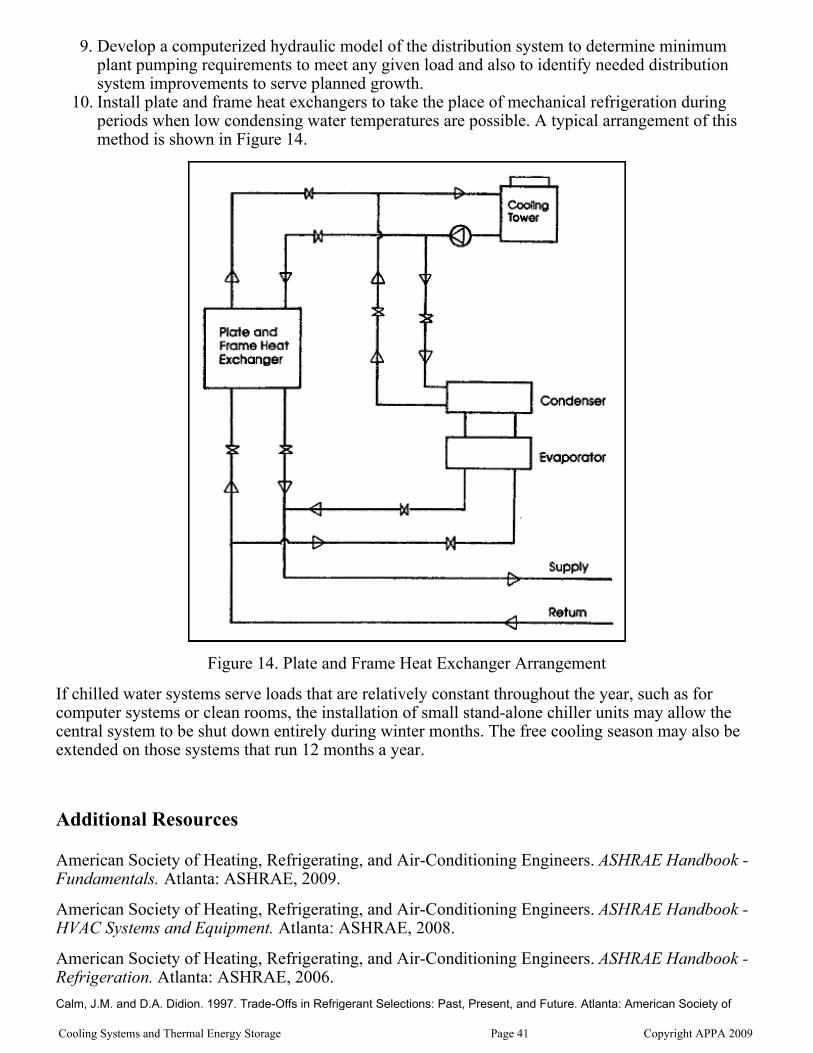
Develop a computerized hydraulic model of the distribution system to determine minimumplant pumping requirements to meet any given load and also to identify needed distributionsystem improvements to serve planned growth.
9.
Install plate and frame heat exchangers to take the place of mechanical refrigeration duringperiods when low condensing water temperatures are possible. A typical arrangement of thismethod is shown in Figure 14.
10.
Figure 14. Plate and Frame Heat Exchanger Arrangement
If chilled water systems serve loads that are relatively constant throughout the year, such as forcomputer systems or clean rooms, the installation of small stand-alone chiller units may allow thecentral system to be shut down entirely during winter months. The free cooling season may also beextended on those systems that run 12 months a year.
Additional Resources
American Society of Heating, Refrigerating, and Air-Conditioning Engineers. ASHRAE Handbook -Fundamentals. Atlanta: ASHRAE, 2009.
American Society of Heating, Refrigerating, and Air-Conditioning Engineers. ASHRAE Handbook -HVAC Systems and Equipment. Atlanta: ASHRAE, 2008.
American Society of Heating, Refrigerating, and Air-Conditioning Engineers. ASHRAE Handbook -Refrigeration. Atlanta: ASHRAE, 2006.
Calm, J.M. and D.A. Didion. 1997. Trade-Offs in Refrigerant Selections: Past, Present, and Future. Atlanta: American Society of
Cooling Systems and Thermal Energy Storage Page 41 Copyright APPA 2009

Heating, Refrigerating and Air-Conditioning Engineers, Inc. See alsohttp://www.trane.com/commercial/issues/environmental/trade-offs05.asp.
CoolTools Chilled Water Plant Design and Specification Guide. Pacific Gas and Electric Company,May 2000.
Cooling Systems and Thermal Energy Storage Page 42 Copyright APPA 2009


![Cooling and Heat Transfer of the IRANCYC-10 …accelconf.web.cern.ch/AccelConf/ipac2016/papers/tupmr015.pdfCOOLING AND HEAT TRANSFER OF THE IRANCYC-10 TRANSMISSION ... p 12-13. [2]](https://img.pdfslide.us/doc/110x75/5b2ab8db7f8b9afb378b58ec/cooling-and-heat-transfer-of-the-irancyc-10-and-heat-transfer-of-the-irancyc-10.jpg)