Embed Size (px)
Citation preview
Models with Closed Cooling
90-8M0086018 AUGUST 2013 Page 6C-1
6C
Cooling SystemSection 6C - Models with Closed Cooling
Table of Contents
Specifications.....................................................................6C-2General Information........................................................... 6C-2
Description..................................................................6C-2Full Loop Closed Cooling Systems.............................6C-3Half Loop Closed Cooling Systems............................ 6C-3
Sterndrive Models with Closed Cooling............................. 6C-3Alpha Models with Closed Cooling............................. 6C-3Bravo Models with Closed Cooling.............................6C-3SeaCore Models.........................................................6C-3Installing the Y‑Fitting................................................. 6C-5Installing the Seawater Supply Hose..........................6C-5
Coolant.............................................................................. 6C-5Coolant Recommendations........................................ 6C-5Maintaining Coolant Level.......................................... 6C-6
Pressure Cap Maintenance and Testing........................... 6C-6Testing the Closed‑Cooling System.................................. 6C-7
Testing Coolant for Alkalinity...................................... 6C-7Pressure Testing the System..................................... 6C-7Seawater Pressure Test............................................. 6C-8
Testing for a Cylinder Head Gasket Leak...................6C-9Thermostat.........................................................................6C-9
Thermostat Housing—Exploded View........................6C-9Thermostat Removal.................................................. 6C-9Thermostat Testing...................................................6C-10Thermostat Installation............................................. 6C-10
Changing Coolant............................................................ 6C-11Closed‑Cooling Section............................................ 6C-11Draining.................................................................... 6C-11Cleaning the Cooling System................................... 6C-12
Heat Exchanger Assembly.............................................. 6C-13Heat Exchanger Assembly—Exploded View............6C-13Testing—Internal Leaks............................................6C-13Blockage...................................................................6C-13Removal................................................................... 6C-13Disassembly............................................................. 6C-14Cleaning and Inspection........................................... 6C-15Repair....................................................................... 6C-15Installation................................................................ 6C-15
Models with Closed Cooling
Page 6C-2 90-8M0086018 AUGUST 2013
Special Tools
Computer Diagnostic System (CDS) Bosch Automotive Service Solutions
4520
Monitors all electrical systems for proper function, diagnostics, and calibrationpurposes. For additional information, pricing, or to order the ComputerDiagnostic System contact:Bosch Automotive Service Solutions28635 Mound RdAttn: Powersport ASRWarren, MI 48092or call:USA ‑ 1‑800‑345‑2233Canada ‑ 800‑345‑2233Europe ‑ 49 6182 959 149Australia ‑ (03) 9544‑6222
SpecificationsSeawater Inlet Recommendations
Description Specification
Minimum flow 106 L/min (28 gal/min) at 4000 RPM
Minimum pressure at full flow(If restrictions are present, the reading could be inaccurate.) 138 kPa (20 psi) at 4000 RPM
Closed‑Cooling System Capacity
Description Specification
Coolant volume in engine, heat exchanger, and exhaust manifolds 19.5 L (20.5 US qt)
Seawater volume in conduits and tube side of heat exchanger 4.3 L (4.5 US qt)
Coolant Specification
Description Part Number
Extended Life Coolant 5/100 (orange color) 92‑877770K1
Thermostat
Description Specification
Thermostat operating temperature 77° C (170° F)
Pressure Cap
Description Specification
Pressure cap rating 110 kPa (16 psi)
General InformationDescription
The cooling system is composed of two separate subsystems: the seawater system and the closed‑cooling system. Theseawater system is similar in function to the fan used in an automobile because it absorbs heat from the closed‑cooling systemas it passes through the heat exchanger. The closed‑cooling system is similar in function to the rest of the cooling system in anautomobile.The coolant recovery system keeps the reservoir full. Normal coolant overflow into the recovery bottle is approximately 230 ml(7.8 fl oz) during warm‑up. The coolant recovery system draws coolant back into the reservoir from the recovery bottle as theengine cools. While there is coolant in the recovery bottle, the reservoir should remain completely full. If not, there is a vacuumleak, usually at the hose leaving the reservoir or the gasket under the recovery filler cap.
Models with Closed Cooling
90-8M0086018 AUGUST 2013 Page 6C-3
Within the heat exchanger, the coolant (antifreeze) flows around the outside of the cooling tubes, while seawater flows throughthe inside of the cooling tubes.
Full Loop Closed Cooling SystemsFull loop closed cooling systems use an ethylene glycol mixture to cool the engine and exhaust manifolds. The hot glycolmixture is circulated through the heat exchanger tubes, engine block, and exhaust manifold water jackets. Heat transfer occurswhen cool raw water from the sea pump flows through the heat exchanger and is discharged into the exhaust stream at theexhaust elbows.All current production MerCruiser engines equipped with closed cooling kits use full loop systems.
Half Loop Closed Cooling SystemsHalf loop closed cooling systems use an ethylene glycol mixture to cool the engine block. The hot glycol mixture is circulatedthrough the heat exchanger tubes and engine block water jackets. Heat transfer occurs when cool raw water from the seapump flows through the heat exchanger and is discharged into the exhaust stream at the exhaust elbows.NOTE: Refer to Section 6D ‑ Water Flow Diagrams for full loop and half loop cooling system flow diagrams.
Sterndrive Models with Closed CoolingAlpha Models with Closed Cooling
Alpha sterndrive models with closed cooling are equipped with a seawater pump on the engine. However, a through‑the‑hull orthrough‑the‑transom seawater pickup is also required in order to meet the minimum flow specifications.
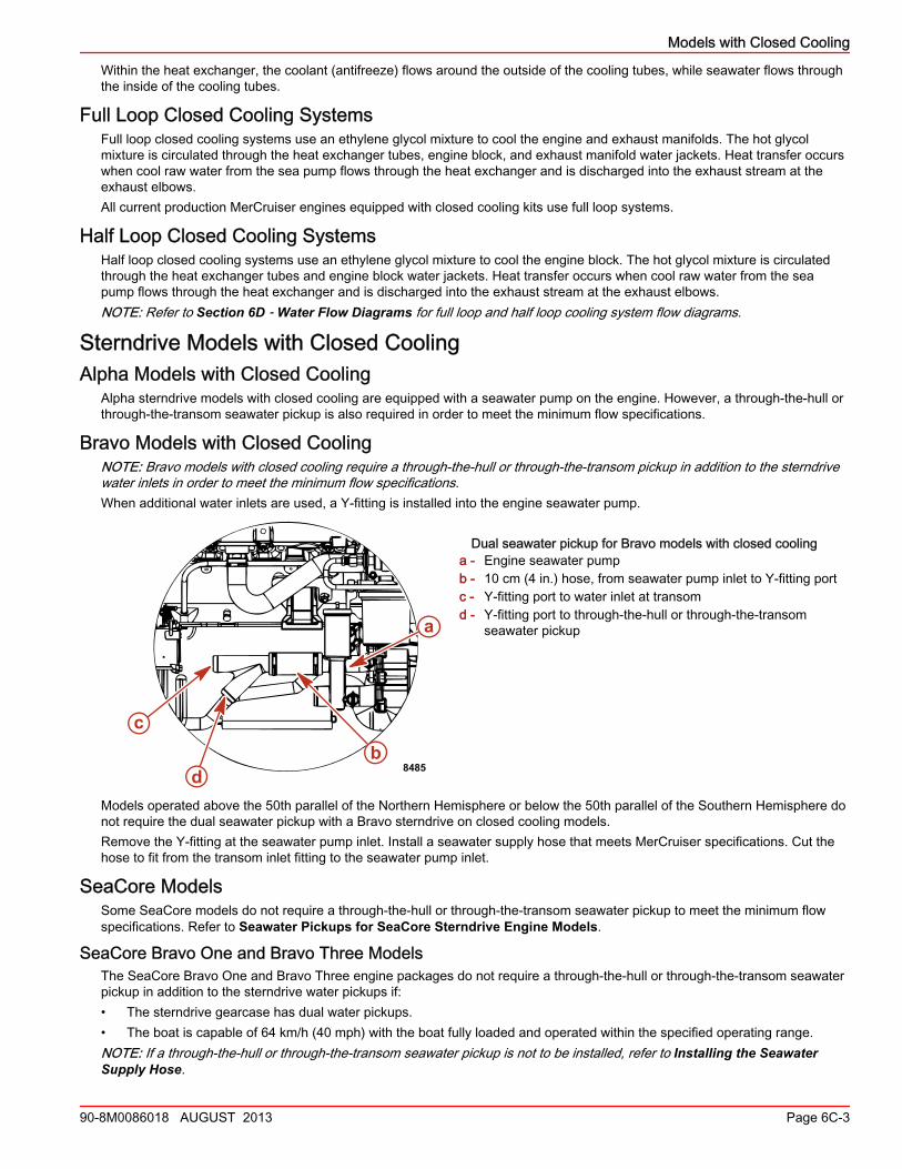
Bravo Models with Closed CoolingNOTE: Bravo models with closed cooling require a through‑the‑hull or through‑the‑transom pickup in addition to the sterndrivewater inlets in order to meet the minimum flow specifications.When additional water inlets are used, a Y‑fitting is installed into the engine seawater pump.
Dual seawater pickup for Bravo models with closed coolinga - Engine seawater pumpb - 10 cm (4 in.) hose, from seawater pump inlet to Y‑fitting portc - Y‑fitting port to water inlet at transomd - Y‑fitting port to through‑the‑hull or through‑the‑transom
seawater pickup
Models operated above the 50th parallel of the Northern Hemisphere or below the 50th parallel of the Southern Hemisphere donot require the dual seawater pickup with a Bravo sterndrive on closed cooling models.Remove the Y‑fitting at the seawater pump inlet. Install a seawater supply hose that meets MerCruiser specifications. Cut thehose to fit from the transom inlet fitting to the seawater pump inlet.
SeaCore ModelsSome SeaCore models do not require a through‑the‑hull or through‑the‑transom seawater pickup to meet the minimum flowspecifications. Refer to Seawater Pickups for SeaCore Sterndrive Engine Models.
SeaCore Bravo One and Bravo Three ModelsThe SeaCore Bravo One and Bravo Three engine packages do not require a through‑the‑hull or through‑the‑transom seawaterpickup in addition to the sterndrive water pickups if:• The sterndrive gearcase has dual water pickups.• The boat is capable of 64 km/h (40 mph) with the boat fully loaded and operated within the specified operating range.NOTE: If a through‑the‑hull or through‑the‑transom seawater pickup is not to be installed, refer to Installing the SeawaterSupply Hose.
a
bc
d 8485
Models with Closed Cooling
Page 6C-4 90-8M0086018 AUGUST 2013
SeaCore Bravo Two ModelsThe SeaCore Bravo Two engine packages must have a through‑the‑hull or through‑the‑transom seawater pickup in addition tothe sterndrive side water pickups. Install the Y‑fitting at the engine's seawater pump inlet. Refer to Installing the Y‑Fitting.
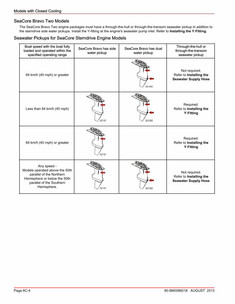
Seawater Pickups for SeaCore Sterndrive Engine Models
Boat speed with the boat fullyloaded and operated within the
specified operating range
SeaCore Bravo has sidewater pickup
SeaCore Bravo has dualwater pickup
Through‑the‑hull orthrough‑the‑transom
seawater pickup
64 km/h (40 mph) or greater
30180
Not required.Refer to Installing the
Seawater Supply Hose
Less than 64 km/h (40 mph)
30181 30180
Required.Refer to Installing the
Y‑Fitting
64 km/h (40 mph) or greater
30181
Required.Refer to Installing the
Y‑Fitting
Any speed ‑Models operated above the 50th
parallel of the NorthernHemisphere or below the 50th
parallel of the SouthernHemisphere. 30181 30180
Not required.Refer to Installing the
Seawater Supply Hose
Models with Closed Cooling
90-8M0086018 AUGUST 2013 Page 6C-5
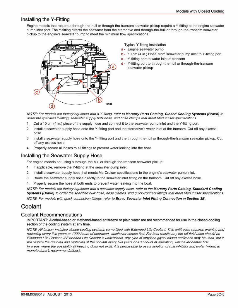
Installing the Y‑FittingEngine models that require a through‑the‑hull or through‑the‑transom seawater pickup require a Y‑fitting at the engine seawaterpump inlet port. The Y‑fitting directs the seawater from the sterndrive and through‑the‑hull or through‑the‑transom seawaterpickup to the engine's seawater pump to meet the minimum flow specifications.
Typical Y-fitting installationa - Engine seawater pumpb - 10 cm (4 in.) Hose, from seawater pump inlet to Y‑fitting portc - Y‑fitting port to water inlet at transomd - Y‑fitting port to through‑the‑hull or through‑the‑transom
seawater pickup
NOTE: For models not factory equipped with a Y‑fitting, refer to Mercury Parts Catalog, Closed‑Cooling Systems (Bravo) toorder the specified Y‑fitting, seawater supply bulk hose, and hose clamps that meet MerCruiser specifications.1. Cut a 10 cm (4 in.) piece of the supply hose and connect it to the seawater pump inlet and the Y‑fitting port.2. Install a seawater supply hose onto the Y‑fitting port and the sterndrive's water inlet at the transom. Cut off any excess
hose.3. Install a seawater supply hose onto the Y‑fitting port and the through‑the‑hull or through‑the‑transom seawater pickup. Cut
off any excess hose.4. Properly secure all hoses to all fittings to prevent water leaking into the boat.
Installing the Seawater Supply HoseFor engine models not using a through‑the‑hull or through‑the‑transom seawater pickup:1. If applicable, remove the Y‑fitting at the seawater pump inlet.2. Install a seawater supply hose that meets MerCruiser specifications to the engine's seawater pump inlet.3. Route the seawater supply hose directly to the seawater inlet fitting on the transom. Cut off any excess hose.4. Properly secure the hose at both ends to prevent water leaking into the boat.NOTE: For models not factory equipped with a seawater supply hose, refer to the Mercury Parts Catalog, Standard‑CoolingSystems (Bravo) to order the specified bulk hose, hose clamps, and quick‑connect fittings that meet MerCruiser specifications.NOTE: For models with quick‑connection fittings, refer to Bravo Seawater Inlet Fitting Connection in Section 2B.
CoolantCoolant Recommendations
IMPORTANT: Alcohol‑based or Methanol‑based antifreeze or plain water are not recommended for use in the closed‑coolingsection of the cooling system at any time.NOTE: All factory installed closed‑cooling systems come filled with Extended Life Coolant. This antifreeze requires draining andreplacing every five years or 1000 hours of operation, whichever comes first. For best results any top‑off fluid used should beExtended Life Coolant. If Extended Life Coolant is unavailable, any type of ethylene glycol based antifreeze may be used, but itwill require the draining and replacing of the coolant every two years or 400 hours of operation, whichever comes first.In areas where the possibility of freezing does not exist, it is permissible to use a solution of rust inhibitor and water (mixed tomanufacturer's recommendations).
a
bc
d 8485
Models with Closed Cooling
Page 6C-6 90-8M0086018 AUGUST 2013
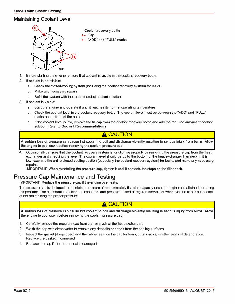
Maintaining Coolant Level
Coolant recovery bottlea - Capb - "ADD" and "FULL" marks
1. Before starting the engine, ensure that coolant is visible in the coolant recovery bottle.2. If coolant is not visible:
a. Check the closed‑cooling system (including the coolant recovery system) for leaks.b. Make any necessary repairs.c. Refill the system with the recommended coolant solution.
3. If coolant is visible:a. Start the engine and operate it until it reaches its normal operating temperature.b. Check the coolant level in the coolant recovery bottle. The coolant level must be between the "ADD" and "FULL"
marks on the front of the bottle.c. If the coolant level is low, remove the fill cap from the coolant recovery bottle and add the required amount of coolant
solution. Refer to Coolant Recommendations.
! CAUTIONA sudden loss of pressure can cause hot coolant to boil and discharge violently resulting in serious injury from burns. Allowthe engine to cool down before removing the coolant pressure cap.
4. Occasionally, ensure that the coolant recovery system is functioning properly by removing the pressure cap from the heatexchanger and checking the level. The coolant level should be up to the bottom of the heat exchanger filler neck. If it islow, examine the entire closed‑cooling section (especially the coolant recovery system) for leaks, and make any necessaryrepairs.IMPORTANT: When reinstalling the pressure cap, tighten it until it contacts the stops on the filler neck.
Pressure Cap Maintenance and TestingIMPORTANT: Replace the pressure cap if the engine overheats.The pressure cap is designed to maintain a pressure of approximately its rated capacity once the engine has attained operatingtemperature. The cap should be cleaned, inspected, and pressure‑tested at regular intervals or whenever the cap is suspectedof not maintaining the proper pressure.
! CAUTIONA sudden loss of pressure can cause hot coolant to boil and discharge violently resulting in serious injury from burns. Allowthe engine to cool down before removing the coolant pressure cap.
1. Carefully remove the pressure cap from the reservoir or the heat exchanger.2. Wash the cap with clean water to remove any deposits or debris from the sealing surfaces.3. Inspect the gasket (if equipped) and the rubber seal on the cap for tears, cuts, cracks, or other signs of deterioration.
Replace the gasket, if damaged.4. Replace the cap if the rubber seal is damaged.
16822
a
b
Models with Closed Cooling
90-8M0086018 AUGUST 2013 Page 6C-7
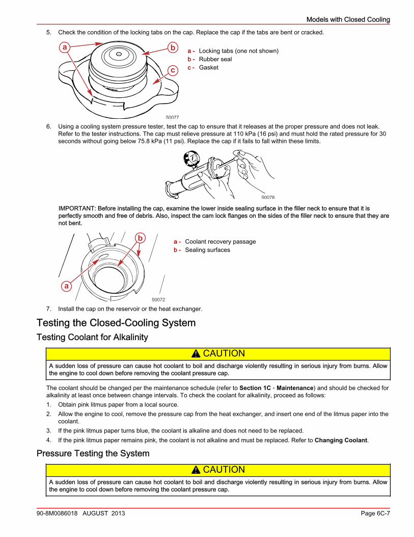
5. Check the condition of the locking tabs on the cap. Replace the cap if the tabs are bent or cracked.
a - Locking tabs (one not shown)b - Rubber sealc - Gasket
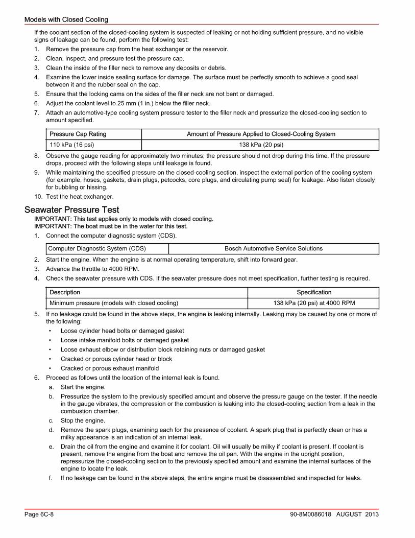
6. Using a cooling system pressure tester, test the cap to ensure that it releases at the proper pressure and does not leak.Refer to the tester instructions. The cap must relieve pressure at 110 kPa (16 psi) and must hold the rated pressure for 30seconds without going below 75.8 kPa (11 psi). Replace the cap if it fails to fall within these limits.
50078
IMPORTANT: Before installing the cap, examine the lower inside sealing surface in the filler neck to ensure that it isperfectly smooth and free of debris. Also, inspect the cam lock flanges on the sides of the filler neck to ensure that they arenot bent.
a - Coolant recovery passageb - Sealing surfaces
7. Install the cap on the reservoir or the heat exchanger.
Testing the Closed‑Cooling SystemTesting Coolant for Alkalinity
! CAUTIONA sudden loss of pressure can cause hot coolant to boil and discharge violently resulting in serious injury from burns. Allowthe engine to cool down before removing the coolant pressure cap.
The coolant should be changed per the maintenance schedule (refer to Section 1C ‑ Maintenance) and should be checked foralkalinity at least once between change intervals. To check the coolant for alkalinity, proceed as follows:1. Obtain pink litmus paper from a local source.2. Allow the engine to cool, remove the pressure cap from the heat exchanger, and insert one end of the litmus paper into the
coolant.3. If the pink litmus paper turns blue, the coolant is alkaline and does not need to be replaced.4. If the pink litmus paper remains pink, the coolant is not alkaline and must be replaced. Refer to Changing Coolant.
Pressure Testing the System
! CAUTIONA sudden loss of pressure can cause hot coolant to boil and discharge violently resulting in serious injury from burns. Allowthe engine to cool down before removing the coolant pressure cap.
50077
a b
c
50072
b
a
Models with Closed Cooling
Page 6C-8 90-8M0086018 AUGUST 2013
If the coolant section of the closed‑cooling system is suspected of leaking or not holding sufficient pressure, and no visiblesigns of leakage can be found, perform the following test:1. Remove the pressure cap from the heat exchanger or the reservoir.2. Clean, inspect, and pressure test the pressure cap.3. Clean the inside of the filler neck to remove any deposits or debris.4. Examine the lower inside sealing surface for damage. The surface must be perfectly smooth to achieve a good seal
between it and the rubber seal on the cap.5. Ensure that the locking cams on the sides of the filler neck are not bent or damaged.6. Adjust the coolant level to 25 mm (1 in.) below the filler neck.7. Attach an automotive‑type cooling system pressure tester to the filler neck and pressurize the closed‑cooling section to
amount specified.
Pressure Cap Rating Amount of Pressure Applied to Closed‑Cooling System
110 kPa (16 psi) 138 kPa (20 psi)
8. Observe the gauge reading for approximately two minutes; the pressure should not drop during this time. If the pressuredrops, proceed with the following steps until leakage is found.
9. While maintaining the specified pressure on the closed‑cooling section, inspect the external portion of the cooling system(for example, hoses, gaskets, drain plugs, petcocks, core plugs, and circulating pump seal) for leakage. Also listen closelyfor bubbling or hissing.
10. Test the heat exchanger.
Seawater Pressure TestIMPORTANT: This test applies only to models with closed cooling.IMPORTANT: The boat must be in the water for this test.1. Connect the computer diagnostic system (CDS).
Computer Diagnostic System (CDS) Bosch Automotive Service Solutions
2. Start the engine. When the engine is at normal operating temperature, shift into forward gear.3. Advance the throttle to 4000 RPM.4. Check the seawater pressure with CDS. If the seawater pressure does not meet specification, further testing is required.
Description Specification
Minimum pressure (models with closed cooling) 138 kPa (20 psi) at 4000 RPM
5. If no leakage could be found in the above steps, the engine is leaking internally. Leaking may be caused by one or more ofthe following:• Loose cylinder head bolts or damaged gasket• Loose intake manifold bolts or damaged gasket• Loose exhaust elbow or distribution block retaining nuts or damaged gasket• Cracked or porous cylinder head or block• Cracked or porous exhaust manifold
6. Proceed as follows until the location of the internal leak is found.a. Start the engine.b. Pressurize the system to the previously specified amount and observe the pressure gauge on the tester. If the needle
in the gauge vibrates, the compression or the combustion is leaking into the closed‑cooling section from a leak in thecombustion chamber.
c. Stop the engine.d. Remove the spark plugs, examining each for the presence of coolant. A spark plug that is perfectly clean or has a
milky appearance is an indication of an internal leak.e. Drain the oil from the engine and examine it for coolant. Oil will usually be milky if coolant is present. If coolant is
present, remove the engine from the boat and remove the oil pan. With the engine in the upright position,repressurize the closed‑cooling section to the previously specified amount and examine the internal surfaces of theengine to locate the leak.
f. If no leakage can be found in the above steps, the entire engine must be disassembled and inspected for leaks.
Models with Closed Cooling
90-8M0086018 AUGUST 2013 Page 6C-9
Testing for a Cylinder Head Gasket LeakA leaking head gasket will cause combustion gas to be forced into the cooling system. The mixture of coolant and tiny airbubbles is a poor heat conductor and will overheat an engine quickly. Compression tests or cooling system pressure checknormally will not detect the leak because the test pressure is far below the combustion pressures that cause the leak. Aneffective test is as follows:IMPORTANT: Operate the boat in the water for this test. It is best to operate the engine at or above cruising speed during thistest. Usually a failed head gasket will not cause the engine to overheat below cruising speed.1. Install a clear plastic hose between the reservoir and the coolant recovery bottle. Use a 91 cm (3 ft) long hose for this test.2. Route this hose so that a "U" is formed.3. Put enough coolant into the hose to fill the center 127 mm (5 in.) of the U‑shape.4. Observe the U‑shape while the engine is operating.
• During idle and warm‑up: Some coolant and air will leave the reservoir.• At cruising speed (2500‑3500 RPM): Coolant and air leaving the reservoir should stop after approximately five
minutes operating at a given RPM. A leaking head gasket will produce air bubbling through the U‑shape, going to thecoolant recovery bottle. The frequency and size of the bubbles will depend on the size of the leak.
• At higher speeds (4000+ RPM): Normal operation is the same as described above. A failed head gasket will causethe bubbles to come faster and may be accompanied by violent, intermittent bursts of coolant.
Do not confuse normal warm‑up expansion with a failed head gasket. Normal warm‑up produces an intermittent flow of coolantthat will stop within approximately five minutes at a given RPM. A head gasket leak will not stop; the one thing that marks afailed head gasket is the continued passage of air. This may be accompanied by violent, intermittent bursts of coolant leavingthe reservoir. If coolant flows evenly from the reservoir at cruising speed, something other than the head gasket is causing theengine to overheat.
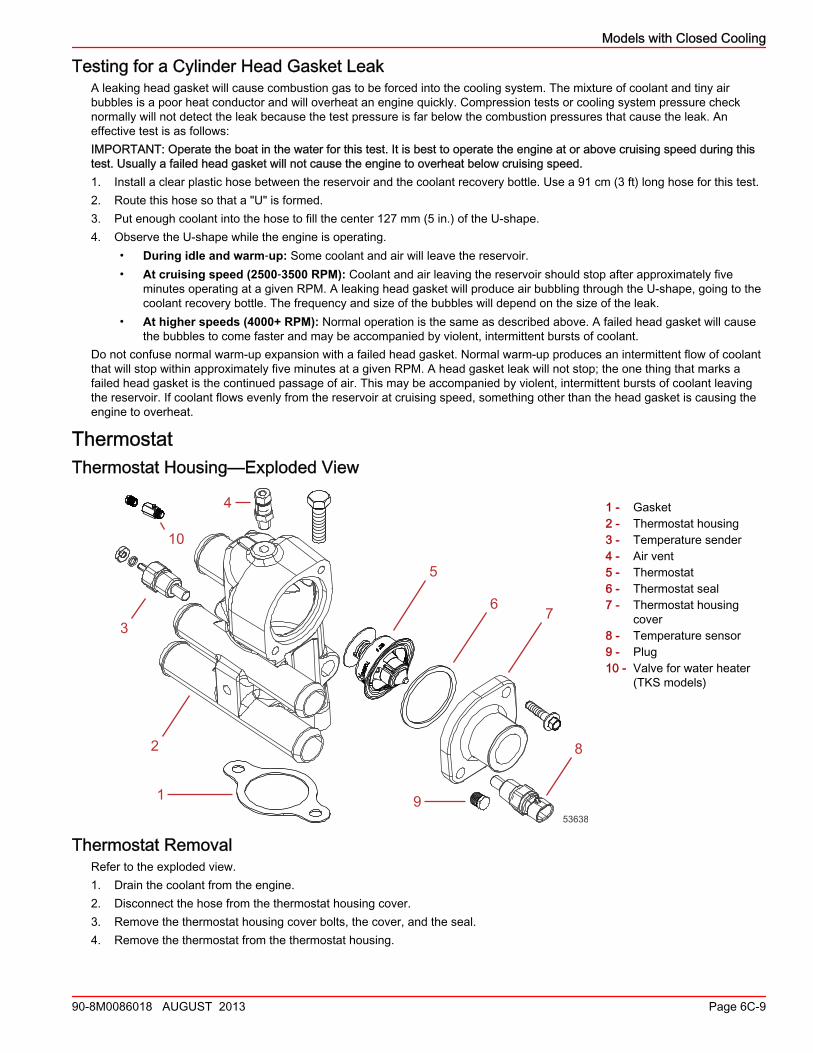
ThermostatThermostat Housing—Exploded View
1 - Gasket2 - Thermostat housing3 - Temperature sender4 - Air vent5 - Thermostat6 - Thermostat seal7 - Thermostat housing
cover8 - Temperature sensor9 - Plug10 - Valve for water heater
(TKS models)
Thermostat RemovalRefer to the exploded view.1. Drain the coolant from the engine.2. Disconnect the hose from the thermostat housing cover.3. Remove the thermostat housing cover bolts, the cover, and the seal.4. Remove the thermostat from the thermostat housing.
1
2
3
4
5
67
8
9
10
53638
Models with Closed Cooling
Page 6C-10 90-8M0086018 AUGUST 2013
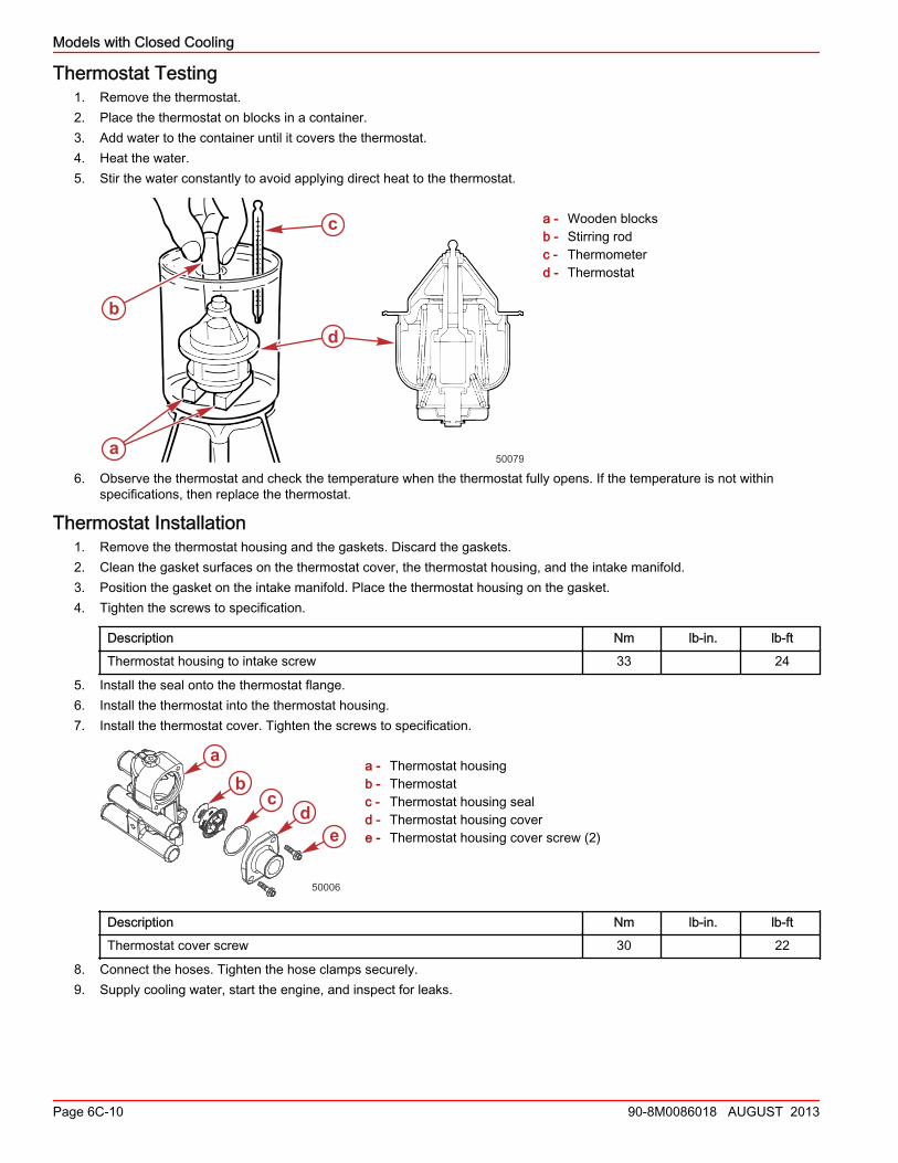
Thermostat Testing1. Remove the thermostat.2. Place the thermostat on blocks in a container.3. Add water to the container until it covers the thermostat.4. Heat the water.5. Stir the water constantly to avoid applying direct heat to the thermostat.
a - Wooden blocksb - Stirring rodc - Thermometerd - Thermostat
6. Observe the thermostat and check the temperature when the thermostat fully opens. If the temperature is not withinspecifications, then replace the thermostat.
Thermostat Installation1. Remove the thermostat housing and the gaskets. Discard the gaskets.2. Clean the gasket surfaces on the thermostat cover, the thermostat housing, and the intake manifold.3. Position the gasket on the intake manifold. Place the thermostat housing on the gasket.4. Tighten the screws to specification.
Description Nm lb‑in. lb‑ft
Thermostat housing to intake screw 33 24
5. Install the seal onto the thermostat flange.6. Install the thermostat into the thermostat housing.7. Install the thermostat cover. Tighten the screws to specification.
a - Thermostat housingb - Thermostatc - Thermostat housing seald - Thermostat housing covere - Thermostat housing cover screw (2)
Description Nm lb‑in. lb‑ft
Thermostat cover screw 30 22
8. Connect the hoses. Tighten the hose clamps securely.9. Supply cooling water, start the engine, and inspect for leaks.
a
b
c
d
50079
de
ab
c
50006
Models with Closed Cooling
90-8M0086018 AUGUST 2013 Page 6C-11
Changing CoolantClosed‑Cooling Section
The engine and exhaust sections of a closed‑cooling system should remain filled year‑round with the recommended coolantsolution. Do not drain the closed‑cooling section for storage, as this will promote rusting of internal surfaces. If the engine willbe exposed to freezing temperatures, fill the closed‑cooling section with Extended Life Coolant or an ethylene glycol antifreezeand water solution. Follow the manufacturer's recommended proportions to protect the engine to the lowest temperature towhich it will be exposed. If necessary, change the coolant using the coolant specified in Coolant Recommendations.
Change IntervalsIf the closed‑cooling system is factory installed, drain and flush the coolant from the closed‑cooling system at least every fiveyears or 1000 hours of operation, whichever comes first. Change the coolant whenever exhaust gases have entered thesystem. If the system is not factory installed or has had anti‑freeze other than Extended Life Coolant added, it must be changedevery two years or 400 hours of operation, whichever comes first.
Draining
! CAUTIONA sudden loss of pressure can cause hot coolant to boil and discharge violently resulting in serious injury from burns. Allowthe engine to cool down before removing the coolant pressure cap.
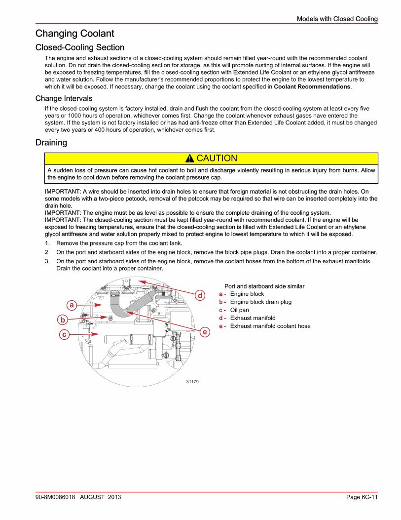
IMPORTANT: A wire should be inserted into drain holes to ensure that foreign material is not obstructing the drain holes. Onsome models with a two‑piece petcock, removal of the petcock may be required so that wire can be inserted completely into thedrain hole.IMPORTANT: The engine must be as level as possible to ensure the complete draining of the cooling system.IMPORTANT: The closed‑cooling section must be kept filled year‑round with recommended coolant. If the engine will beexposed to freezing temperatures, ensure that the closed‑cooling section is filled with Extended Life Coolant or an ethyleneglycol antifreeze and water solution properly mixed to protect engine to lowest temperature to which it will be exposed.1. Remove the pressure cap from the coolant tank.2. On the port and starboard sides of the engine block, remove the block pipe plugs. Drain the coolant into a proper container.3. On the port and starboard sides of the engine block, remove the coolant hoses from the bottom of the exhaust manifolds.
Drain the coolant into a proper container.
Port and starboard side similara - Engine blockb - Engine block drain plugc - Oil pand - Exhaust manifolde - Exhaust manifold coolant hose
a
b
c
d
e
31179
Models with Closed Cooling
Page 6C-12 90-8M0086018 AUGUST 2013
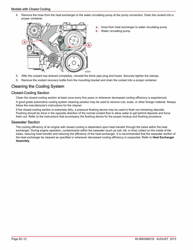
4. Remove the hose from the heat exchanger to the water circulating pump at the pump connection. Drain the coolant into aproper container.
a - Hose from heat exchanger to water circulating pumpb - Water circulating pump
5. After the coolant has drained completely, reinstall the block pipe plug and hoses. Securely tighten the clamps.6. Remove the coolant recovery bottle from the mounting bracket and drain the coolant into a proper container.
Cleaning the Cooling SystemClosed-Cooling Section
Clean the closed‑cooling section at least once every five years or whenever decreased cooling efficiency is experienced.A good grade automotive cooling system cleaning solution may be used to remove rust, scale, or other foreign material. Alwaysfollow the manufacturer's instructions for the cleaner.If the closed‑cooling section is extremely dirty, a pressure flushing device may be used to flush out remaining deposits.Flushing should be done in the opposite direction of the normal coolant flow to allow water to get behind deposits and forcethem out. Refer to the instructions that accompany the flushing device for the proper hookup and flushing procedure.
Seawater SectionThe cooling efficiency of an engine with closed cooling is dependent upon heat transfer through the tubes within the heatexchanger. During engine operation, contaminants within the seawater (such as salt, silt, or lime) collect on the inside of thetubes, reducing heat transfer and reducing the efficiency of the heat exchanger. It is recommended that the seawater section ofthe heat exchanger be cleaned as specified or whenever decreased cooling efficiency is suspected. Refer to Heat ExchangerAssembly.
50081
ab
Models with Closed Cooling
90-8M0086018 AUGUST 2013 Page 6C-13
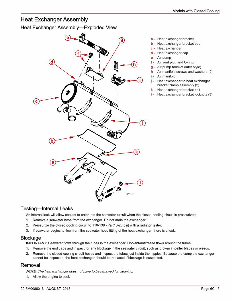
Heat Exchanger AssemblyHeat Exchanger Assembly—Exploded View
a - Heat exchanger bracketb - Heat exchanger bracket padc - Heat exchangerd - Heat exchanger cape - Air pumpf - Air vent plug and O‑ringg - Air pump bracket (later style)h - Air manifold screws and washers (2)i - Air manifoldj - Heat exchanger to heat exchanger
bracket clamp assembly (2)k - Heat exchanger bracket boltl - Heat exchanger bracket locknuts (3)
Testing—Internal LeaksAn internal leak will allow coolant to enter into the seawater circuit when the closed‑cooling circuit is pressurized.1. Remove a seawater hose from the exchanger. Do not drain the exchanger.2. Pressurize the closed‑cooling circuit to 110‑138 kPa (16‑20 psi) with a radiator tester.3. If seawater begins to flow from the seawater hose fitting of the heat exchanger, there is a leak.
BlockageIMPORTANT: Seawater flows through the tubes in the exchanger. Coolant/antifreeze flows around the tubes.1. Remove the end caps and inspect for any blockage in the seawater circuit, such as broken impeller blades or weeds.2. Remove the closed‑cooling circuit hoses and inspect the tubes just inside the nipples. Because the complete exchanger
cannot be inspected, the heat exchanger should be replaced if blockage is suspected.
RemovalNOTE: The heat exchanger does not have to be removed for cleaning.1. Allow the engine to cool.
a
c
b
l
k
j
i
hd
f
e g
31187
Models with Closed Cooling
Page 6C-14 90-8M0086018 AUGUST 2013
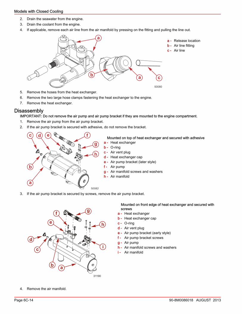
2. Drain the seawater from the engine.3. Drain the coolant from the engine.4. If applicable, remove each air line from the air manifold by pressing on the fitting and pulling the line out.
a - Release locationb - Air line fittingc - Air line
5. Remove the hoses from the heat exchanger.6. Remove the two large hose clamps fastening the heat exchanger to the engine.7. Remove the heat exchanger.
DisassemblyIMPORTANT: Do not remove the air pump and air pump bracket if they are mounted to the engine compartment.1. Remove the air pump from the air pump bracket.2. If the air pump bracket is secured with adhesive, do not remove the bracket.
Mounted on top of heat exchanger and secured with adhesivea - Heat exchangerb - O‑ringc - Air vent plugd - Heat exchanger cape - Air pump bracket (later style)f - Air pumpg - Air manifold screws and washersh - Air manifold
3. If the air pump bracket is secured by screws, remove the air pump bracket.
Mounted on front edge of heat exchanger and secured withscrews
a - Heat exchangerb - Heat exchanger capc - O‑ringd - Air vent pluge - Air pump bracket (early style)f - Air pump bracket screwsg - Air pumph - Air manifold screws and washersi - Air manifold
4. Remove the air manifold.
a
b a c
50080
50082
a
b
c d e fg
h
ab
c
di
h
gf
e
31190
Models with Closed Cooling
90-8M0086018 AUGUST 2013 Page 6C-15
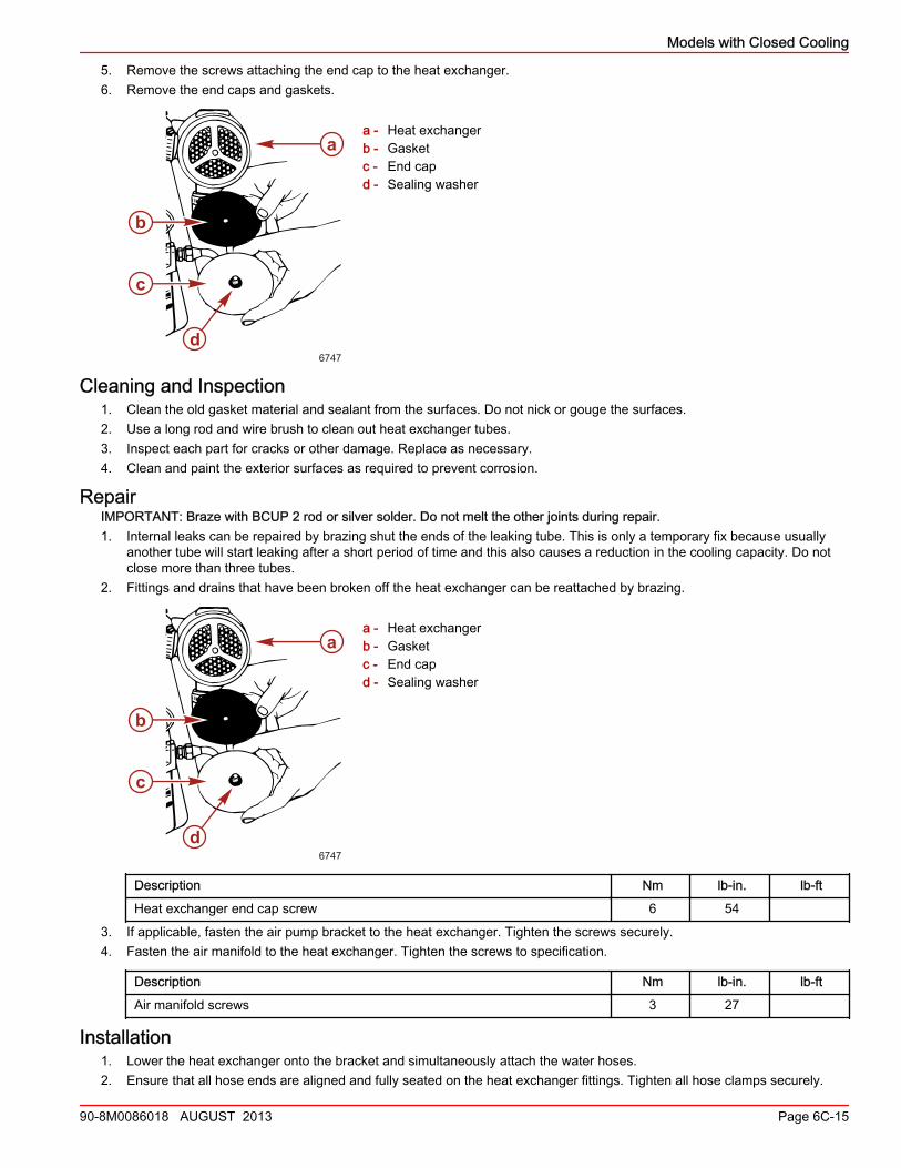
5. Remove the screws attaching the end cap to the heat exchanger.6. Remove the end caps and gaskets.
a - Heat exchangerb - Gasketc - End capd - Sealing washer
Cleaning and Inspection1. Clean the old gasket material and sealant from the surfaces. Do not nick or gouge the surfaces.2. Use a long rod and wire brush to clean out heat exchanger tubes.3. Inspect each part for cracks or other damage. Replace as necessary.4. Clean and paint the exterior surfaces as required to prevent corrosion.
RepairIMPORTANT: Braze with BCUP 2 rod or silver solder. Do not melt the other joints during repair.1. Internal leaks can be repaired by brazing shut the ends of the leaking tube. This is only a temporary fix because usually
another tube will start leaking after a short period of time and this also causes a reduction in the cooling capacity. Do notclose more than three tubes.
2. Fittings and drains that have been broken off the heat exchanger can be reattached by brazing.
a - Heat exchangerb - Gasketc - End capd - Sealing washer
Description Nm lb‑in. lb‑ft
Heat exchanger end cap screw 6 54
3. If applicable, fasten the air pump bracket to the heat exchanger. Tighten the screws securely.4. Fasten the air manifold to the heat exchanger. Tighten the screws to specification.
Description Nm lb‑in. lb‑ft
Air manifold screws 3 27
Installation1. Lower the heat exchanger onto the bracket and simultaneously attach the water hoses.2. Ensure that all hose ends are aligned and fully seated on the heat exchanger fittings. Tighten all hose clamps securely.
a
d
b
c
6747
a
d
b
c
6747
Models with Closed Cooling
Page 6C-16 90-8M0086018 AUGUST 2013
3. Install the large hose clamps around the heat exchanger bracket and heat exchanger. Position the rubber hosesunderneath the bracket to prevent the bracket from directly contacting the hose clamps and breaking them.
a - Hose clampb - Rubber hose
4. Tighten the hose clamps to specification.
Description Nm lb‑in. lb‑ft
Hose clamps around heat exchanger and bracket 3 26
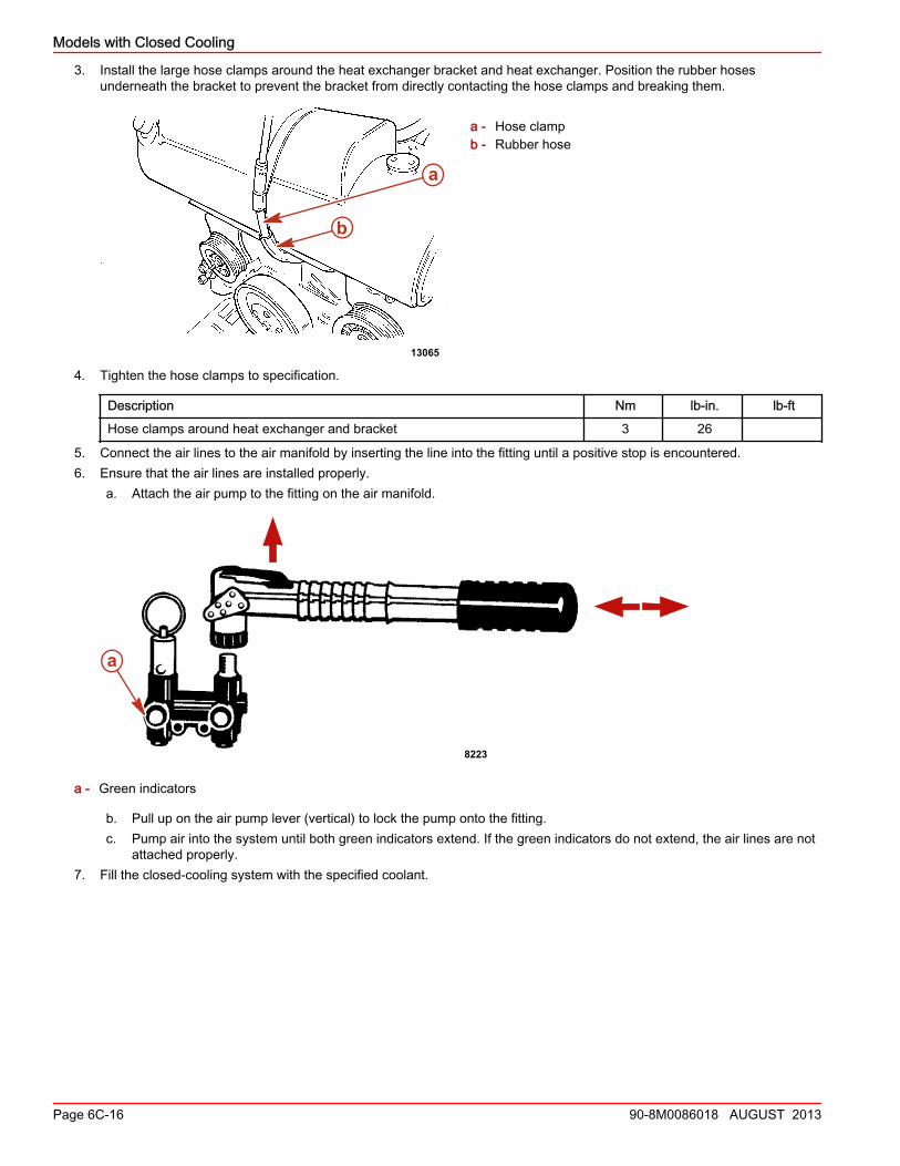
5. Connect the air lines to the air manifold by inserting the line into the fitting until a positive stop is encountered.6. Ensure that the air lines are installed properly.
a. Attach the air pump to the fitting on the air manifold.
a - Green indicators
b. Pull up on the air pump lever (vertical) to lock the pump onto the fitting.c. Pump air into the system until both green indicators extend. If the green indicators do not extend, the air lines are not
attached properly.7. Fill the closed‑cooling system with the specified coolant.
a
b
13065
a
8223