Embed Size (px)
Citation preview
Co
olin
g F
an
sIn
trod
uctio
nFM
AC
Inp
ut
MRS
AC
Inp
ut
Va
riab
le F
low
MRS
AC
Inp
ut
MU
DC
Inp
ut
Lo
ng
-Life
MD
ED
C In
pu
tM
DS/M
DA
C In
pu
tM
BD
C In
pu
tM
BD
AC
Inp
ut
MF
DC
Inp
ut
MFD
Th
erm
osta
tsA
ccesso
ries
Insta
llatio
n
Co
olin
g M
od
ule
Axia
l Flo
w F
an
sC
en
trifug
al B
low
ers
Cro
ss F
low
Fan
s
E-121
Page
Introduction ···························································· E-122MF Series ······························································ E-124MFD Series ··························································· E-128
Cooling Fans
Cross Flow Fans
AC Input
MF Series
DC Input
MFD Series
Co
olin
g F
an
s
E-122 ORIENTAL MOTOR GENERAL CATALOG 2009/2010
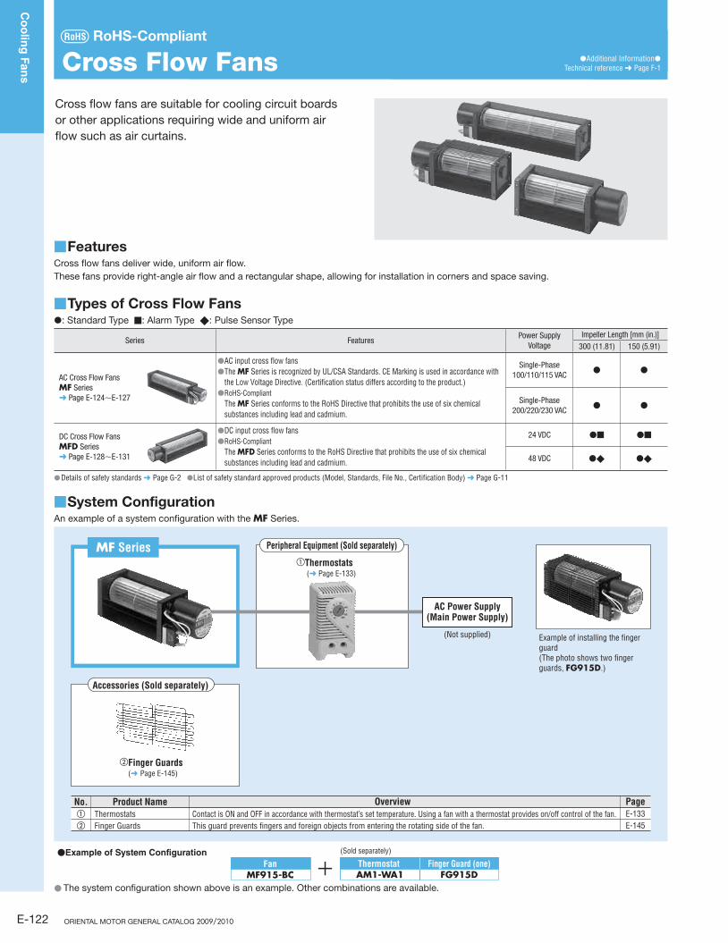
Cross flow fans are suitable for cooling circuit boards
or other applications requiring wide and uniform air
flow such as air curtains.
Cross Flow Fans ●Additional Information●Technical reference ➜ Page F-1
RoHS-Compliant
Features ■Cross flow fans deliver wide, uniform air flow.
These fans provide right-angle air flow and a rectangular shape, allowing for installation in corners and space saving.
Types of Cross Flow Fans ■●: Standard Type ■: Alarm Type ◆: Pulse Sensor Type
Series FeaturesPower Supply
VoltageImpeller Length [mm (in.)]
300 (11.81) 150 (5.91)
AC Cross Flow FansMF Series➜ Page E-124∼E-127
●AC input cross flow fans● The MF Series is recognized by UL/CSA Standards. CE Marking is used in accordance with
the Low Voltage Directive. (Certification status differs according to the product.) ● RoHS-Compliant
The MF Series conforms to the RoHS Directive that prohibits the use of six chemical substances including lead and cadmium.
Single-Phase 100/110/115 VAC
● ●
Single-Phase 200/220/230 VAC
● ●
DC Cross Flow FansMFD Series➜ Page E-128∼E-131
●DC input cross flow fans● RoHS-Compliant
The MFD Series conforms to the RoHS Directive that prohibits the use of six chemical substances including lead and cadmium.
24 VDC ●■ ●■
48 VDC ●◆ ●◆
Details of safety standards ● ➜ Page G-2 ●List of safety standard approved products (Model, Standards, File No., Certification Body) ➜ Page G-11
System Configuration ■An example of a system configuration with the MF Series.
MF Series
Accessories (Sold separately)
Peripheral Equipment (Sold separately)
①Thermostats (➜ Page E-133)
●Example of System Configuration (Sold separately)
②Finger Guards(➜ Page E-145)
No. Product Name Overview PageE-133① Thermostats Contact is ON and OFF in accordance with thermostat’s set temperature. Using a fan with a thermostat provides on/off control of the fan.E-145② Finger Guards This guard prevents fingers and foreign objects from entering the rotating side of the fan.
AC Power Supply(Main Power Supply)
(Not supplied)
Thermostat AM1-WA1
FanMF915-BC
Finger Guard (one)FG915D
Example of installing the finger guard(The photo shows two finger guards, FG915D.)
The system configuration shown above is an example. Other combinations are available. ●
E-123
Co
olin
g F
an
sIn
trod
uctio
nFM
AC
Inp
ut
MRS
AC
Inp
ut
Va
riab
le F
low
MRS
AC
Inp
ut
MU
DC
Inp
ut
Lo
ng
-Life
MD
ED
C In
pu
tM
DS/M
DA
C In
pu
tM
BD
C In
pu
tM
BD
AC
Inp
ut
MF
DC
Inp
ut
MFD
Th
erm
osta
tsA
ccesso
ries
Insta
llatio
n
Co
olin
g M
od
ule
Axia
l Flo
w F
an
sC
en
trifug
al B
low
ers
Cro
ss F
low
Fan
s
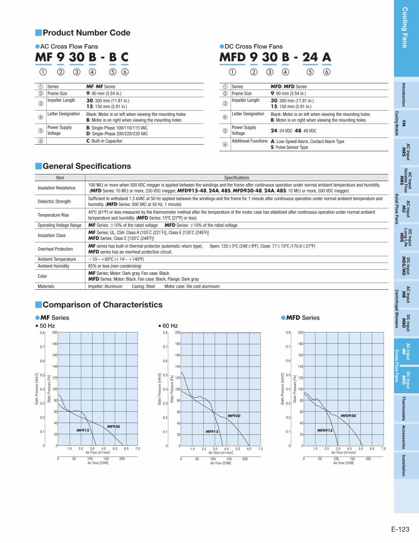
Product Number Code ■
AC Cross Flow Fans ●
MF 9 30 B - B C① ③② ④ ⑤ ⑥
① Series MF: MF Series② Frame Size 9: 90 mm (3.54 in.)
③Impeller Length 30: 300 mm (11.81 in.)
15: 150 mm (5.91 in.)
④Letter Designation Blank: Motor is on left when viewing the mounting holes
B: Motor is on right when viewing the mounting holes
⑤Power Supply Voltage
B: Single-Phase 100/110/115 VACD: Single-Phase 200/220/230 VAC
⑥ C: Built-in Capacitor
DC Cross Flow Fans ●
MFD 9 30 B - 24 A① ③② ④ ⑥⑤
① Series MFD: MFD Series② Frame Size 9: 90 mm (3.54 in.)
③Impeller Length 30: 300 mm (11.81 in.)
15: 150 mm (5.91 in.)
④Letter Designation Blank: Motor is on left when viewing the mounting holes
B: Motor is on right when viewing the mounting holes
⑤Power Supply Voltage 24: 24 VDC 48: 48 VDC
⑥Additional Functions A: Low-Speed Alarm, Contact Alarm Type
S: Pulse Sensor Type
General Specifications ■
Item Specifications
Insulation Resistance100 MΩ or more when 500 VDC megger is applied between the windings and the frame after continuous operation under normal ambient temperature and humidity. (MFD Series: 10 MΩ or more, 250 VDC megger, MFD915-48, 24A, 48S, MFD930-48, 24A, 48S: 10 MΩ or more, 500 VDC megger)
Dielectric StrengthSufficient to withstand 1.5 kVAC at 50 Hz applied between the windings and the frame for 1 minute after continuous operation under normal ambient temperature and humidity. (MFD Series: 500 VAC at 50 Hz, 1 minute)
Temperature Rise45ºC (81ºF) or less measured by the thermometer method after the temperature of the motor case has stabilized after continuous operation under normal ambient temperature and humidity. (MFD Series: 15ºC [27ºF] or less)
Operating Voltage Range MF Series: ±10% of the rated voltage MFD Series: ±10% of the rated voltage
Insulation ClassMF Series; UL, CSA: Class A [105˚C (221˚F)], Class E [120˚C (248˚F)]MFD Series; Class E [120˚C (248˚F)]
Overheat ProtectionMF series has built-in thermal protector (automatic return type). Open: 120±5ºC (248±9ºF), Close: 77±15ºC (170.6±27ºF)MFD series has an overheat protection circuit.
Ambient Temperature −10∼+60ºC (+14∼+140ºF)Ambient Humidity 85% or less (non-condensing)
ColorMF Series; Motor: Dark gray, Fan case: BlackMFD Series; Motor: Black, Fan case: Black, Flange: Dark gray
Materials Impeller: Aluminum Casing: Steel Motor case: Die cast aluminum
Comparison of Characteristics ■
MF ● Series50 Hz ●
1.0 2.0 3.0 4.0 5.0 6.0 7.00
20
40
60
80
100
120
140
200
180
160
MF930MF915
Air Flow [m3/min]
Stat
ic P
ress
ure
[Pa]
0
0.8
0.7
0.6
0.2
0.3
0.4
0.5
0.1
Stat
ic P
ress
ure
[inH2
O]
0 15010050 200Air Flow [CFM]
60 Hz ●
1.0 2.0 3.0 4.0 5.0 6.0 7.00
20
40
60
80
100
120
140
160
180
200
MF930
MF915
Air Flow [m3/min]
Stat
ic P
ress
ure
[Pa]
0
0.8
0.7
0.6
0.2
0.3
0.4
0.5
0.1
Stat
ic P
ress
ure
[inH2
O]
0 15010050 200Air Flow [CFM]
MFD ● Series
1.0 2.0 3.0 4.0 5.0 6.0 7.00
20
40
60
80
100
120
140
160
180
200
MFD930
MFD915
Air Flow [m3/min]
Stat
ic P
ress
ure
[Pa]
0
0.8
0.7
0.6
0.2
0.3
0.4
0.5
0.1
Stat
ic P
ress
ure
[inH2
O]
0 15010050 200Air Flow [CFM]
Co
olin
g F
an
s
E-124 ORIENTAL MOTOR GENERAL CATALOG 2009/2010 Features E-122 / System Configuration E-122 / General Specifications E-123
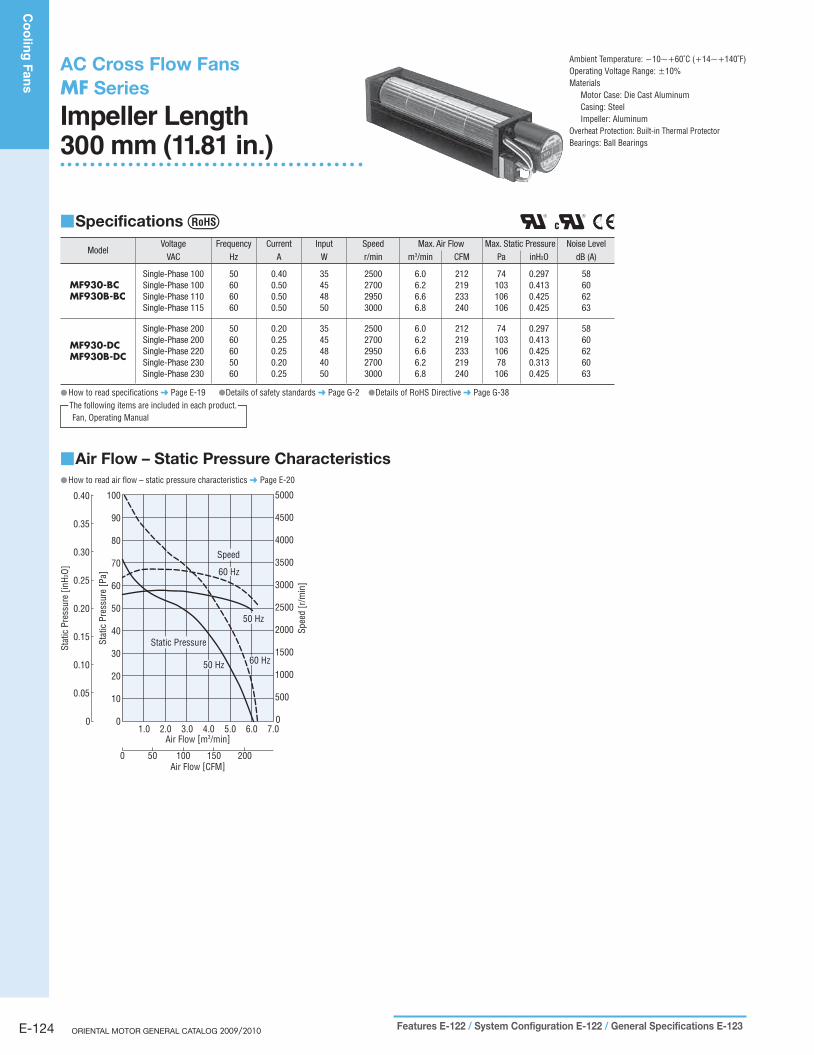
AC Cross Flow FansMF Series
Impeller Length 300 mm (11.81 in.)
Specifications ■
ModelVoltage Frequency Current Input Speed Max. Air Flow Max. Static Pressure Noise Level
VAC Hz A W r/min m3/min CFM Pa inH2O dB (A)
MF930-BCMF930B-BC
Single-Phase 100Single-Phase 100Single-Phase 110Single-Phase 115
50606060
0.400.500.500.50
35454850
2500270029503000
6.06.26.66.8
212219233240
74103106106
0.2970.4130.4250.425
58606263
MF930-DCMF930B-DC
Single-Phase 200Single-Phase 200Single-Phase 220Single-Phase 230Single-Phase 230
5060605060
0.200.250.250.200.25
3545484050
25002700295027003000
6.06.26.66.26.8
212219233219240
7410310678106
0.2970.4130.4250.3130.425
5860626063
How to read specifications ● ➜ Page E-19 ●Details of safety standards ➜ Page G-2 ●Details of RoHS Directive ➜ Page G-38
Fan, Operating ManualThe following items are included in each product.
Ambient Temperature: −10∼+60˚C (+14∼+140˚F)Operating Voltage Range: ±10%Materials
Motor Case: Die Cast AluminumCasing: SteelImpeller: Aluminum
Overheat Protection: Built-in Thermal ProtectorBearings: Ball Bearings
Air Flow – Static Pressure Characteristics ■How to read air flow – static pressure characteristics ● ➜ Page E-20
1.0 2.0 3.0 4.0 5.0 6.0 7.00
10
20
30
40
50
60
70
80
90
100
0
500
1500
2000
2500
3000
3500
4000
4500
5000
1000
Spee
d [r
/min
]
Air Flow [m3/min]
0 50 100 150 200Air Flow [CFM]
Stat
ic P
ress
ure
[Pa]
0
0.10
0.05
0.20
0.15
0.25
0.30
0.35
0.40
Stat
ic P
ress
ure
[inH2
O]
60 Hz
50 Hz
60 Hz
50 Hz
Speed
Static Pressure
E-125
Co
olin
g F
an
sIn
trod
uctio
nFM
AC
Inp
ut
MRS
AC
Inp
ut
Va
riab
le F
low
MRS
AC
Inp
ut
MU
DC
Inp
ut
Lo
ng
-Life
MD
ED
C In
pu
tM
DS/M
DA
C In
pu
tM
BD
C In
pu
tM
BD
AC
Inp
ut
MF
DC
Inp
ut
MFD
Th
erm
osta
tsA
ccesso
ries
Insta
llatio
n
Co
olin
g M
od
ule
Axia
l Flo
w F
an
sC
en
trifug
al B
low
ers
Cro
ss F
low
Fan
s
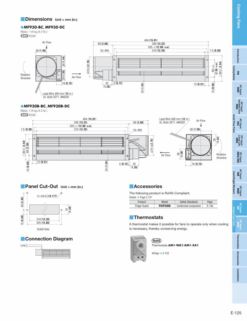
Dimensions ■ Unit = mm (in.)
MF930-BC ● , MF930-DCMass: 1.9 kg (4.2 lb.)
E034
Air Flow
Air Flow
Rotation Direction
38 (1.50)
39 ( 1
.54)
38 ( 1
.50)
19 (0.75) 32(1.26)
3 (0.12)
15 ( 0
.59)13 (0.51)
34 ( 1
.34)
336 (13.23)68 (2.68)404 (15.91)
310 (12.20) 7.5 (0.30)
Lead Wire 300 mm (12 in.)UL Style 3271, AWG20
ϕ70
(ϕ2.
76)
60±
0.5
( 2.3
6±0.
02)
□90
( □3.
54)
325±2 (12.80±0.08)16×M4
MF930B-BC ● , MF930B-DCMass: 1.9 kg (4.2 lb.)
E035
ϕ70
( ϕ2.
76)
325±2 (12.80±0.08)
□90
( □3.
54)
60 ( 2
.36)
Air Flow
Air Flow
32(1.26)
3 (0.12)
15 ( 0
.59) 13 (0.51)
34 ( 1
.34)
310 (12.20)
336 (13.23) 68 (2.68)
7.5 (0.30)
404 (15.91)
38 (1.50)
39( 1
.54)
38( 1
.50)
19 (0.75)
Lead Wire 300 mm (12 in.)UL Style 3271, AWG20
Rotation Direction
16×M4
Panel Cut-Out ■ Unit = mm (in.)
4×ϕ4.5 (ϕ0.177)
60 ( 2
.36)
310 (12.20)325 (12.80)
34( 1
.34)
15 ( 0
.59)
Outlet Side
Connection Diagram ■Line
Accessories ■
The following product is RoHS-Compliant.
Details ➜ Page E-137
Product Model Safety Standards PageFinger Guard FG930D Conformed component E-145
Thermostats ■
A thermostat makes it possible for fans to operate only when cooling
is necessary, thereby conserving energy.
Thermostats AM1-WA1/AM1-XA1
●Page ➜ E-133
Co
olin
g F
an
s
E-126 ORIENTAL MOTOR GENERAL CATALOG 2009/2010 Features E-122 / System Configuration E-122 / General Specifications E-123
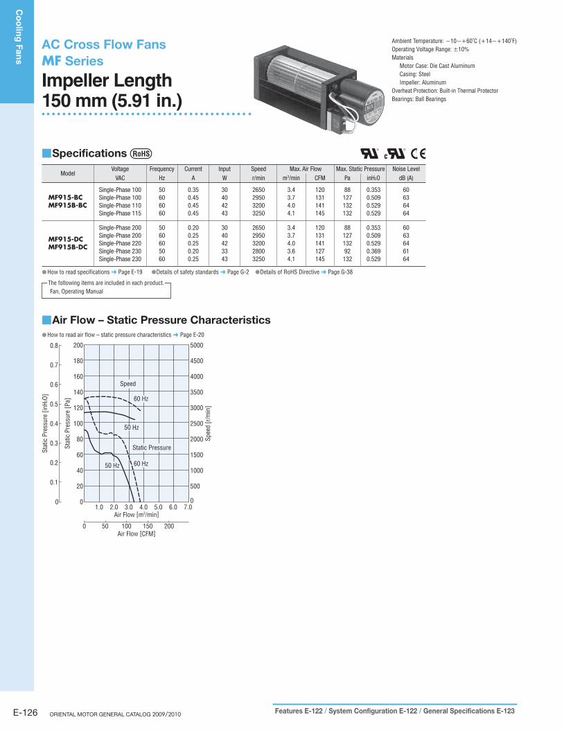
AC Cross Flow FansMF Series
Impeller Length 150 mm (5.91 in.)
Specifications ■
ModelVoltage Frequency Current Input Speed Max. Air Flow Max. Static Pressure Noise Level
VAC Hz A W r/min m3/min CFM Pa inH2O dB (A)
MF915-BCMF915B-BC
Single-Phase 100Single-Phase 100Single-Phase 110Single-Phase 115
50606060
0.350.450.450.45
30404243
2650295032003250
3.43.74.04.1
120131141145
88127132132
0.3530.5090.5290.529
60636464
MF915-DCMF915B-DC
Single-Phase 200Single-Phase 200Single-Phase 220Single-Phase 230Single-Phase 230
5060605060
0.200.250.250.200.25
3040423343
26502950320028003250
3.43.74.03.64.1
120131141127145
8812713292132
0.3530.5090.5290.3690.529
6063646164
How to read specifications ● ➜ Page E-19 ●Details of safety standards ➜ Page G-2 ●Details of RoHS Directive ➜ Page G-38
Fan, Operating ManualThe following items are included in each product.
Ambient Temperature: −10∼+60˚C (+14∼+140˚F)Operating Voltage Range: ±10%Materials
Motor Case: Die Cast AluminumCasing: SteelImpeller: Aluminum
Overheat Protection: Built-in Thermal ProtectorBearings: Ball Bearings
Air Flow – Static Pressure Characteristics ■How to read air flow – static pressure characteristics ● ➜ Page E-20
1.0 2.0 3.0 4.0 5.0 6.0 7.0
Stat
ic P
ress
ure
[Pa]
Spee
d [r
/min
]
00
50020
100040
150060
200080
2500100
3000120
3500140
4000
4500
5000
160
180
200
Air Flow [m3/min]
0 50 100 150 200Air Flow [CFM]
0
0.1
0.3
0.4
0.5
0.6
0.7
0.8
0.2
Stat
ic P
ress
ure
[inH2
O]
Speed
60 Hz
50 Hz
50 Hz
Static Pressure
60 Hz
E-127
Co
olin
g F
an
sIn
trod
uctio
nFM
AC
Inp
ut
MRS
AC
Inp
ut
Va
riab
le F
low
MRS
AC
Inp
ut
MU
DC
Inp
ut
Lo
ng
-Life
MD
ED
C In
pu
tM
DS/M
DA
C In
pu
tM
BD
C In
pu
tM
BD
AC
Inp
ut
MF
DC
Inp
ut
MFD
Th
erm
osta
tsA
ccesso
ries
Insta
llatio
n
Co
olin
g M
od
ule
Axia
l Flo
w F
an
sC
en
trifug
al B
low
ers
Cro
ss F
low
Fan
s
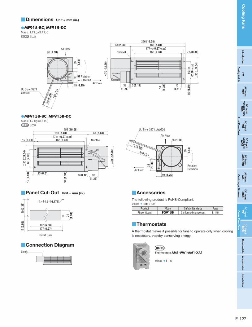
Dimensions ■ Unit = mm (in.)
MF915-BC ● , MF915-DCMass: 1.7 kg (3.7 lb.)
E036
Air Flow
Air Flow38 (1.50)
39( 1
.54)
38( 1
.50)
19 (0.75)
10 ( 0
.39)
300
( 12)
32(1.26)
3 (0.12)
15 ( 0
.59)13
(0.51)34( 1
.34)
188 (7.40)68 (2.68)256 (10.08)
162 (6.38) 7.5 (0.30)
UL Style 3271AWG20
Rotation Direction
ϕ70
(ϕ2.
76)
177±2 (6.97±0.08)
60±
0.5
( 2.3
6±0.
02)
□90
( □3.
54)
16×M4
MF915B-BC ● , MF915B-DCMass: 1.7 kg (3.7 lb.)
E037
177±2 (6.97±0.08)
□90
( □3.
54)
60 ( 2
.36)
ϕ70
( ϕ2.
76)
Air Flow
Air Flow162 (6.38)7.5 (0.30)
188 (7.40) 68 (2.68)256 (10.08)
38 (1.50)
38 ( 1
.50)
10 (0.39)300 (12)
UL Style 3271, AWG20
15 ( 0
.59) 13 (0.51)
34 ( 1
.34)
32(1.26)
3 (0.12) 19 (0.75)
39( 1
.54)
Rotation Direction
16×M4
Panel Cut-Out ■ Unit = mm (in.)
4×ϕ4.5 (ϕ0.177)
60 ( 2
.36)
162 (6.38)177 (6.97)
34( 1
.34)
15 ( 0
.59)
Outlet Side
Connection Diagram ■Line
Accessories ■
The following product is RoHS-Compliant.
Details ➜ Page E-137
Product Model Safety Standards PageFinger Guard FG915D Conformed component E-145
Thermostats ■
A thermostat makes it possible for fans to operate only when cooling
is necessary, thereby conserving energy.
Thermostats AM1-WA1/AM1-XA1
●Page ➜ E-133
Co
olin
g F
an
s
E-128 ORIENTAL MOTOR GENERAL CATALOG 2009/2010 Features E-122 / System Configuration E-122 / General Specifications E-123
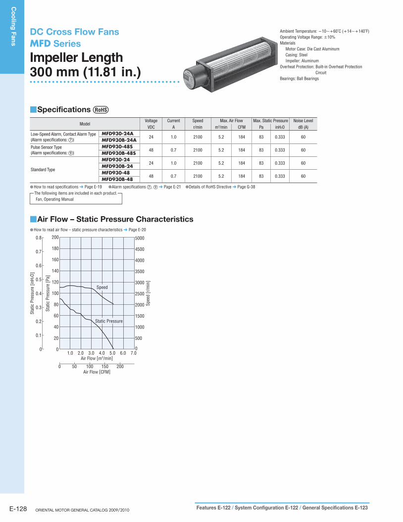
DC Cross Flow FansMFD Series
Impeller Length 300 mm (11.81 in.)
Specifications ■
ModelVoltage Current Speed Max. Air Flow Max. Static Pressure Noise Level
VDC A r/min m3/min CFM Pa inH2O dB (A)
Low-Speed Alarm, Contact Alarm Type(Alarm specifications: ⑦)
MFD930-24A24 1.0 2100 5.2 184 83 0.333 60
MFD930B-24APulse Sensor Type(Alarm specifications: ⑨)
MFD930-48S48 0.7 2100 5.2 184 83 0.333 60
MFD930B-48S
Standard Type
MFD930-2424 1.0 2100 5.2 184 83 0.333 60
MFD930B-24MFD930-48
48 0.7 2100 5.2 184 83 0.333 60MFD930B-48
How to read specifications ● ➜ Page E-19 ●Alarm specifications ⑦, ⑨ ➜ Page E-21 ●Details of RoHS Directive ➜ Page G-38
Fan, Operating ManualThe following items are included in each product.
Ambient Temperature: −10∼+60˚C (+14∼+140˚F)Operating Voltage Range: ±10%Materials
Motor Case: Die Cast AluminumCasing: SteelImpeller: Aluminum
Overheat Protection: Built-in Overheat Protection Circuit
Bearings: Ball Bearings
Air Flow – Static Pressure Characteristics ■How to read air flow – static pressure characteristics ● ➜ Page E-20
1.0 2.0 3.0 4.0 5.0 6.0 7.0
Stat
ic P
ress
ure
[Pa]
Spee
d [r
/min
]
00
50020
100040
150060
200080
2500100
3000120
3500
4000
4500
5000
140
160
180
200
Air Flow [m3/min]
0 50 100 150 200Air Flow [CFM]
0
0.1
0.3
0.4
0.5
0.6
0.7
0.8
0.2
Stat
ic P
ress
ure
[inH2
O]
Static Pressure
Speed
E-129
Co
olin
g F
an
sIn
trod
uctio
nFM
AC
Inp
ut
MRS
AC
Inp
ut
Va
riab
le F
low
MRS
AC
Inp
ut
MU
DC
Inp
ut
Lo
ng
-Life
MD
ED
C In
pu
tM
DS/M
DA
C In
pu
tM
BD
C In
pu
tM
BD
AC
Inp
ut
MF
DC
Inp
ut
MFD
Th
erm
osta
tsA
cc
es
so
ries
Insta
llatio
n
Co
olin
g M
od
ule
Axia
l Flo
w F
an
sC
en
trifug
al B
low
ers
Cro
ss
Flo
w F
an
s
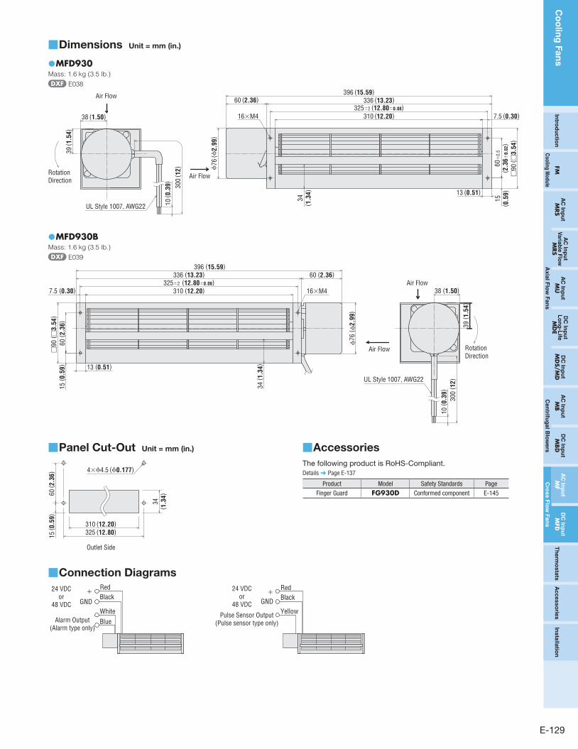
Dimensions ■ Unit = mm (in.)
MFD930 ●Mass: 1.6 kg (3.5 lb.)
E038
38 (1.50)
39 ( 1
.54)
310 (12.20)
336 (13.23)396 (15.59)
7.5 (0.30)
60 (2.36)
15( 0
.59)13 (0.51)
34( 1
.34)
10 ( 0
.39)
Air Flow
Air FlowRotation Direction
300
( 12)
UL Style 1007, AWG22ϕ
76 (ϕ
2.99
)
325±2 (12.80±0.08)
□90
( □3.
54)
60±
0.5
( 2.3
6±0.
02)
16×M4
MFD930B ●Mass: 1.6 kg (3.5 lb.)
E039
325±2 (12.80±0.08)
□90
( □3.
54)
60 ( 2
.36)
ϕ76
( ϕ2.
99)
RotationDirection
38 (1.50)
39 ( 1
.54)
10 ( 0
.39)
300
( 12)
310 (12.20)
336 (13.23)396 (15.59)
60 (2.36)Air Flow
Air Flow
UL Style 1007, AWG22
7.5 (0.30)
15 ( 0
.59) 13 (0.51)
34 ( 1
.34)
16×M4
Panel Cut-Out ■ Unit = mm (in.)
4×ϕ4.5 (ϕ0.177)
60 ( 2
.36)
310 (12.20)325 (12.80)
34( 1
.34)
15 ( 0
.59)
Outlet Side
Connection Diagrams ■
24 VDCor
48 VDC
+
GND
RedBlack
Alarm Output (Alarm type only)
WhiteBlue
24 VDCor
48 VDC
+
GND
RedBlack
Pulse Sensor Output(Pulse sensor type only)
Yellow
Accessories ■
The following product is RoHS-Compliant.
Details ➜ Page E-137
Product Model Safety Standards PageFinger Guard FG930D Conformed component E-145
Co
olin
g F
an
s
E-130 ORIENTAL MOTOR GENERAL CATALOG 2009/2010 Features E-122 / System Configuration E-122 / General Specifications E-123
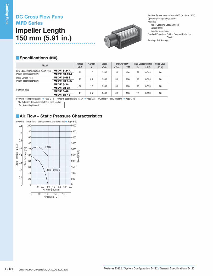
DC Cross Flow FansMFD Series
Impeller Length150 mm (5.91 in.)
Specifications ■
ModelVoltage Current Speed Max. Air Flow Max. Static Pressure Noise Level
VDC A r/min m3/min CFM Pa inH2O dB (A)
Low-Speed Alarm, Contact Alarm Type(Alarm specifications: ⑦)
MFD915-24A24 1.0 2500 3.0 106 98 0.393 60
MFD915B-24APulse Sensor Type(Alarm specifications: ⑨)
MFD915-48S48 0.7 2500 3.0 106 98 0.393 60
MFD915B-48S
Standard Type
MFD915-2424 1.0 2500 3.0 106 98 0.393 60
MFD915B-24MFD915-48
48 0.7 2500 3.0 106 98 0.393 60MFD915B-48
How to read specifications ● ➜ Page E-19 ●Alarm specifications ⑦, ⑨ ➜ Page E-21 ●Details of RoHS Directive ➜ Page G-38
Fan, Operating ManualThe following items are included in each product.
Ambient Temperature: −10∼+60˚C (+14∼+140˚F)Operating Voltage Range: ±10%Materials
Motor Case: Die Cast AluminumCasing: SteelImpeller: Aluminum
Overheat Protection: Built-in Overheat Protection Circuit
Bearings: Ball Bearings
Air Flow – Static Pressure Characteristics ■How to read air flow – static pressure characteristics ● ➜ Page E-20
1.0 2.0 3.0 4.0 5.0 6.0 7.0
Stat
ic P
ress
ure
[Pa]
Spee
d [r
/min
]
00
50020
100040
150060
200080
2500100
3000120
3500140
4000
4500
5000
160
180
200
0
0.1
0.3
0.4
0.5
0.6
0.7
0.8
0.2
Stat
ic P
ress
ure
[inH2
O]
Air Flow [m3/min]
0 50 100 150 200Air Flow [CFM]
Static Pressure
Speed
E-131
Co
olin
g F
an
sIn
trod
uctio
nFM
AC
Inp
ut
MRS
AC
Inp
ut
Va
riab
le F
low
MRS
AC
Inp
ut
MU
DC
Inp
ut
Lo
ng
-Life
MD
ED
C In
pu
tM
DS/M
DA
C In
pu
tM
BD
C In
pu
tM
BD
AC
Inp
ut
MF
DC
Inp
ut
MFD
Th
erm
osta
tsA
cc
es
so
ries
Insta
llatio
n
Co
olin
g M
od
ule
Axia
l Flo
w F
an
sC
en
trifug
al B
low
ers
Cro
ss
Flo
w F
an
s
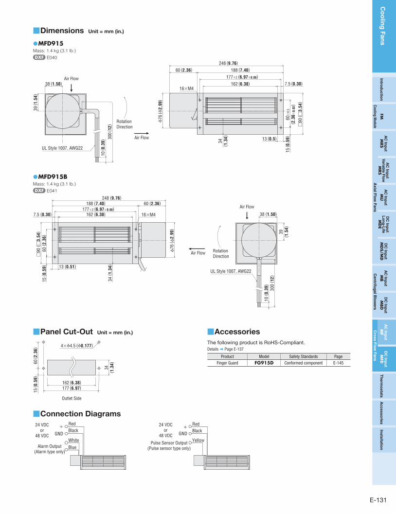
Dimensions ■ Unit = mm (in.)
MFD915 ●Mass: 1.4 kg (3.1 lb.)
E040
Air Flow
Air Flow38 (1.50)
39 ( 1
.54)
162 (6.38)
188 (7.40)248 (9.76)
7.5 (0.30)
60 (2.36)
15 ( 0
.59)13 (0.5)
34( 1
.34)
10 ( 0
.39)
300
( 12)
Rotation Direction
UL Style 1007, AWG22
60±
0.5
( 2.3
6±0.
02)
□90
( □3.
54)
177±2 (6.97±0.08)
ϕ76
(ϕ2.
99)
16×M4
MFD915B ●Mass: 1.4 kg (3.1 lb.)
E041
177±2 (6.97±0.08)
□90
( □3.
54)
60 ( 2
.36)
ϕ76
( ϕ2.
99)
Air Flow
Air Flow
10 ( 0
.39) 300
( 12)
162 (6.38)
188 (7.40)248 (9.76)
7.5 (0.30)
60 (2.36)
Rotation Direction
UL Style 1007, AWG22
15 ( 0
.59) 13 (0.51)
34 ( 1
.34)
38 (1.50)
39( 1
.54)
16×M4
Panel Cut-Out ■ Unit = mm (in.)
4×ϕ4.5 (ϕ0.177)
60 ( 2
.36)
162 (6.38)177 (6.97)
34( 1
.34)
15 ( 0
.59)
Outlet Side
Connection Diagrams ■
24 VDCor
48 VDC
+
GND
RedBlack
Alarm Output (Alarm type only)
WhiteBlue
24 VDCor
48 VDC
+
GND
RedBlack
Pulse Sensor Output(Pulse sensor type only)
Yellow
Accessories ■
The following product is RoHS-Compliant.
Details ➜ Page E-137
Product Model Safety Standards PageFinger Guard FG915D Conformed component E-145

Co
olin
g F
an
s
E-132 ORIENTAL MOTOR GENERAL CATALOG 2009/2010