Embed Size (px)
Citation preview
Zadravec, M., et al.: Cooling Analysis of a Light Emitting Diode Automotive Fog Lamp THERMAL SCIENCE, Year 2017, Vol. 21, No. 1B, pp. 757-766 757
COOLING ANALYSIS OF A LIGHT EMITTING DIODE AUTOMOTIVE FOG LAMP
by
Matej ZADRAVECa, Matjaž RAMŠAKa*, Jure RAVNIKa, Matjaž HRIBERŠEKa, and Jernej SLAVONECb
a Faculty of Mechanical Engineering, University of Maribor, Maribor, Slovenia b HELLA Saturnus Slovenija d. o. o., Ljubljana, Slovenia
Original scientific paper DOI: 10.2298/TSCI140829140Z
Efficiency of cooling fins inside of a light emitting diode fog lamp is studied using computational fluid dynamics. Diffusion in heat sink, natural convection and ra-diation are the main principles of the simulated heat transfer. The Navier-Stokes equations were solved by the computational fluid dynamics code, including Mon-te Carlo radiation model and no additional turbulence model was needed. The numerical simulation is tested using the existing lamp geometry and temperature measurements. The agreement is excellent inside of few degrees at all measured points. The main objective of the article is to determine the cooling effect of vari-ous heat sink parts. Based on performed simulations, some heat sink parts are found to be very ineffective. The geometry and heat sink modifications are pro-posed. While radiation influence is significant, compressible effects are found to be minor. Key words: heat transfer, cooling of electronic devices, cooling fins,
light emitting diode automotive lamp, compressible flow
Introduction
In automotive industry, cooling of light emitting devices in head and fog lamps pre-sents a great challenge. This is partially due to a relatively small volume of lamps, giving a rise accumulation of heat and in a larger extent due to the concentrated heat sources and con-sequently high local temperatures presenting problems to supporting materials and affecting light emitting characteristics [1, 2]. This is especially true in the case of light emitting diode (LED) light sources, which are characterized by extremely high heat flux densities. Effective LED cooling almost always leads to the use of attachment of large heat transfer areas, most commonly in a form of a finned surface.
The fined surface has two principal properties: increasing heat transfer area and in-creasing fluid flow pressure drop. In forced heat convection applications finning the surface always results in higher heat transfer, however, in natural convection cases increasing heat transfer is not guaranteed. In the work of Introini et al. [3] the well-known benchmark case of natural convection in a closed squared cavity of De Vahl Davis [4] was modified by introduc-tion of finned walls in a shape similar to a post stamp. The resulting Nusselt number was low-er for a 3% at a low Rayleight number value of 103 and for even 16% at Ra = 108. The reason
–––––––––––––– * Corresponding author, email: [email protected]
Zadravec, M., et al.: Cooling Analysis of a Light Emitting Diode Automotive Fog Lamp 758 THERMAL SCIENCE, Year 2017, Vol. 21, No. 1B, pp. 757-766
was increased wall flow resistance resulting in a weaker velocity field and consequently much lower heat flux. Using this logic, the application of fins inside a LED automotive lamp might become questionable, which is why in this paper, the effectiveness of various fin sections of the heat sink are investigated using the real fog lamp geometry.
Ensuring low LED junction temperature on printed circuit board (PCB) is essential in guaranteeing the stability, reliability, and long service lifetime. There are many articles dedicated to the LED cooling subject, for example [5, 6]. They cover different cooling princi-ples on, as just fin heat sink, liquid cooling, thermoelectric cooling, heat pipe, micro jet, etc. At present, fin heat sink cooling is still the most wide spread in the automotive industry.
In the work of Christensen and Graham [7] a very simple fin geometry was numeri-cally investigated using constant heat transfer coefficients calculated using standard correla-tions for a natural and forced convection heat transfer regime. A detailed experimental meas-urements of the wall temperatures and fluid flow velocities inside an automotive headlight us-ing laser doppler anemometer was performed by Sousa et al. [8]. The steady-state operating regime was characterized as a vortex-dominated flow. Significant thermal stratification was also found. In the recent experimental and numerical work done by Wang et al. [9] the LED junction was effectively cooled using heat pipes. The problem geometry consisted only of PCB and heat sink connected by heat pipes. The numerical simulation was performed using FloEFD.
There are not many articles dealing with the complex geometries of real lamps. Let us just mention the numerical simulation reported by Mielke et al. [10] using very simple ge-ometry of the typical bulb head lamp surrounded with air. The problem was discretized using relative coarse mesh consisted of 850,000 fluid cells calculated using Audi Radiation model and Star-CD.
The originality of the present paper lays in a successful numerical simulation of complex thermo-hydraulic conditions inside of real modern automotive LED fog lamp mod-elled in detail. In addition, the effectiveness of various heat sink fin sections is determined. Based on this research the guidelines for heat sink modifications are proposed. The compress-ibility and radiation influence are investigated.
Problem definition
Geometry definition
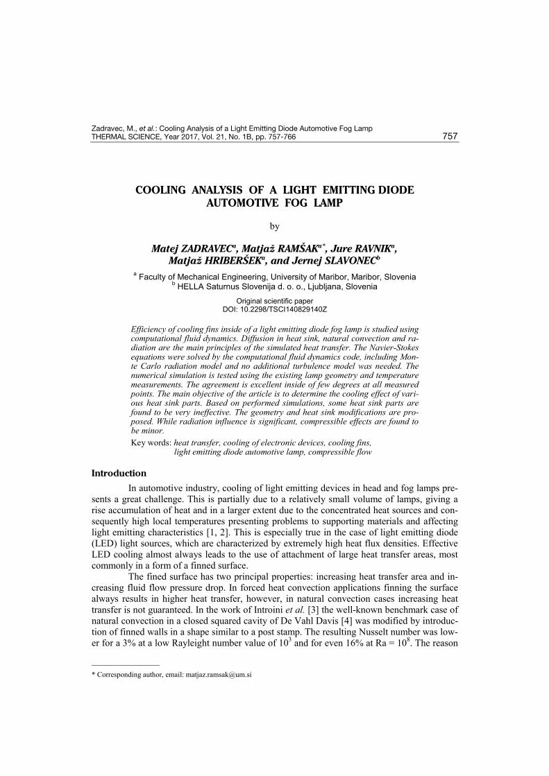
Fog lamps are typically placed in the low-er front end of the car and are surrounded by air on the front side and the under hood of the car on the other end. Since such a configuration is difficult to reproduce in an experimental envi-ronment, the fog lamp in our case was placed in a simplified environment, consisting of a fog lamp, surrounded by ambient air. The problem set-up was the same as used in experiment. The interior of the fog lamp, fig. 1, is modelled in detail and consists of the bezel, reflector, heat
sink, PCB, supported electronics and cover. The PCB with electronic and four LED is located directly on the heat sink. The LED junction dimension is a 3 mm square. Interior of the fog lamp is enveloped with housing and cover lens.
Figure 1. The fog lamp parts and the interior with PCB and LED position
Zadravec, M., et al.: Cooling Analysis of a Light Emitting Diode Automotive Fog Lamp THERMAL SCIENCE, Year 2017, Vol. 21, No. 1B, pp. 757-766 759
Heat sink versions
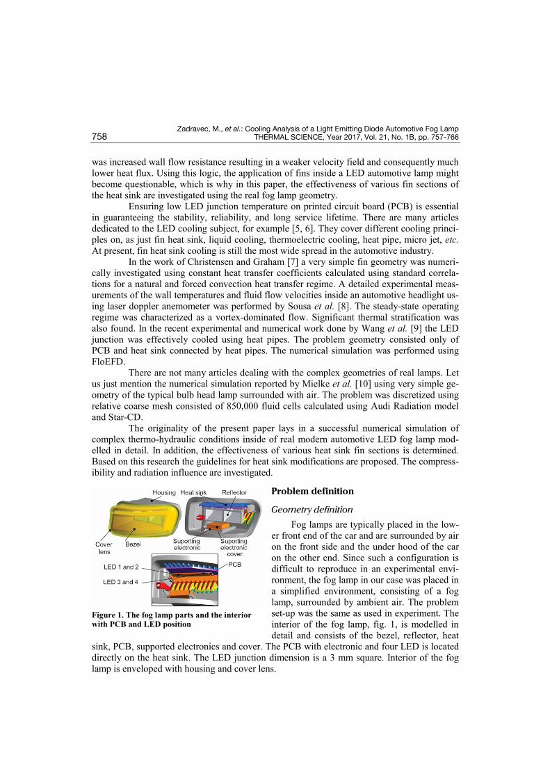
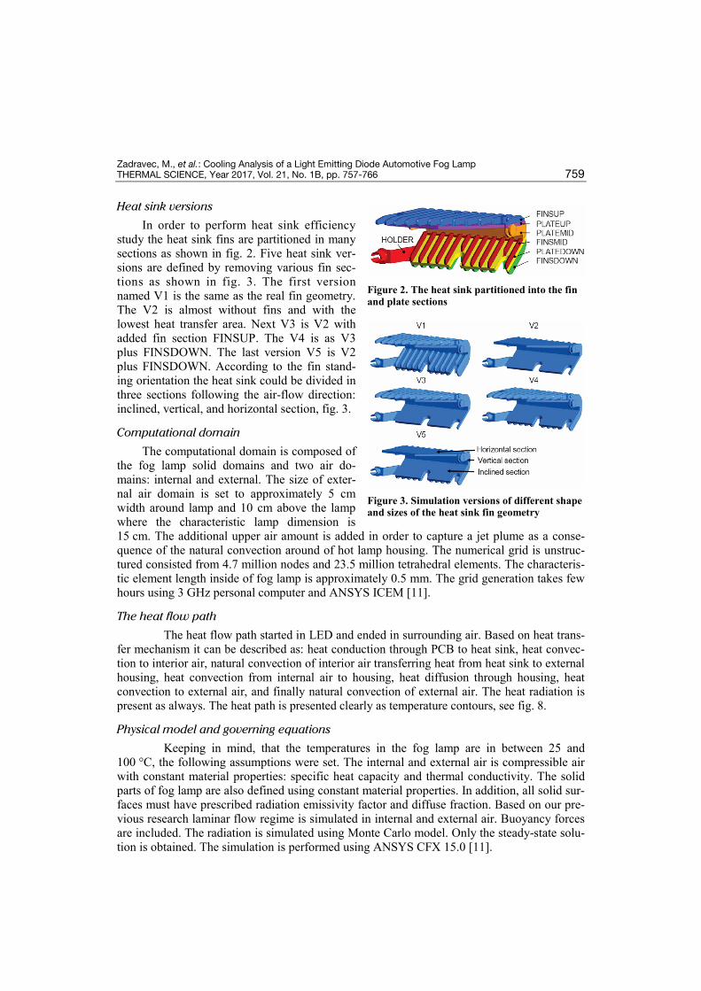
In order to perform heat sink efficiency study the heat sink fins are partitioned in many sections as shown in fig. 2. Five heat sink ver-sions are defined by removing various fin sec-tions as shown in fig. 3. The first version named V1 is the same as the real fin geometry. The V2 is almost without fins and with the lowest heat transfer area. Next V3 is V2 with added fin section FINSUP. The V4 is as V3 plus FINSDOWN. The last version V5 is V2 plus FINSDOWN. According to the fin stand-ing orientation the heat sink could be divided in three sections following the air-flow direction: inclined, vertical, and horizontal section, fig. 3.
Computational domain
The computational domain is composed of the fog lamp solid domains and two air do-mains: internal and external. The size of exter-nal air domain is set to approximately 5 cm width around lamp and 10 cm above the lamp where the characteristic lamp dimension is 15 cm. The additional upper air amount is added in order to capture a jet plume as a conse-quence of the natural convection around of hot lamp housing. The numerical grid is unstruc-tured consisted from 4.7 million nodes and 23.5 million tetrahedral elements. The characteris-tic element length inside of fog lamp is approximately 0.5 mm. The grid generation takes few hours using 3 GHz personal computer and ANSYS ICEM [11].
The heat flow path
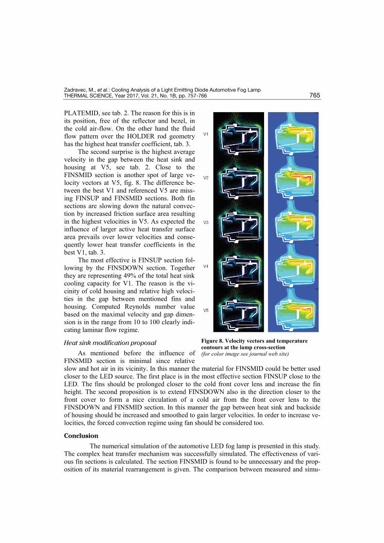
The heat flow path started in LED and ended in surrounding air. Based on heat trans-fer mechanism it can be described as: heat conduction through PCB to heat sink, heat convec-tion to interior air, natural convection of interior air transferring heat from heat sink to external housing, heat convection from internal air to housing, heat diffusion through housing, heat convection to external air, and finally natural convection of external air. The heat radiation is present as always. The heat path is presented clearly as temperature contours, see fig. 8.
Physical model and governing equations
Keeping in mind, that the temperatures in the fog lamp are in between 25 and 100 °C, the following assumptions were set. The internal and external air is compressible air with constant material properties: specific heat capacity and thermal conductivity. The solid parts of fog lamp are also defined using constant material properties. In addition, all solid sur-faces must have prescribed radiation emissivity factor and diffuse fraction. Based on our pre-vious research laminar flow regime is simulated in internal and external air. Buoyancy forces are included. The radiation is simulated using Monte Carlo model. Only the steady-state solu-tion is obtained. The simulation is performed using ANSYS CFX 15.0 [11].
Figure 2. The heat sink partitioned into the fin and plate sections
Figure 3. Simulation versions of different shape and sizes of the heat sink fin geometry
Zadravec, M., et al.: Cooling Analysis of a Light Emitting Diode Automotive Fog Lamp 760 THERMAL SCIENCE, Year 2017, Vol. 21, No. 1B, pp. 757-766
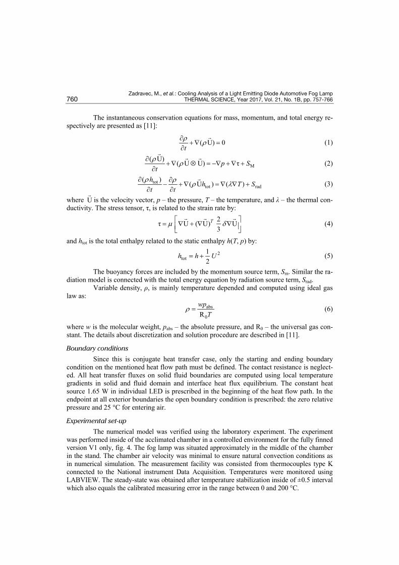
The instantaneous conservation equations for mass, momentum, and total energy re-spectively are presented as [11]:
( U) 0tρ ρ∂+∇ =
∂
(1)
M( U) ( U U) τp S
tρ ρ∂
+∇ ⊗ = −∇ +∇ +∂
(2)
tottot rad
( ) ( U ) ( )h h T St t
ρ ρ ρ λ∂ ∂
− +∇ = ∇ ∇ +∂ ∂
(3)
where U
is the velocity vector, p – the pressure, T – the temperature, and λ – the thermal con-ductivity. The stress tensor, τ, is related to the strain rate by:
2τ U ( U) U3
Tµ δ = ∇ + ∇ ∇
(4)
and htot is the total enthalpy related to the static enthalpy h(T, p) by:
2tot
12
h h U= + (5)
The buoyancy forces are included by the momentum source term, Sm. Similar the ra-diation model is connected with the total energy equation by radiation source term, Srad.
Variable density, ρ, is mainly temperature depended and computed using ideal gas law as:
abs
0Rwp
Tρ = (6)
where w is the molecular weight, pabs – the absolute pressure, and R0 – the universal gas con-stant. The details about discretization and solution procedure are described in [11].
Boundary conditions
Since this is conjugate heat transfer case, only the starting and ending boundary condition on the mentioned heat flow path must be defined. The contact resistance is neglect-ed. All heat transfer fluxes on solid fluid boundaries are computed using local temperature gradients in solid and fluid domain and interface heat flux equilibrium. The constant heat source 1.65 W in individual LED is prescribed in the beginning of the heat flow path. In the endpoint at all exterior boundaries the open boundary condition is prescribed: the zero relative pressure and 25 °C for entering air.
Experimental set-up
The numerical model was verified using the laboratory experiment. The experiment was performed inside of the acclimated chamber in a controlled environment for the fully finned version V1 only, fig. 4. The fog lamp was situated approximately in the middle of the chamber in the stand. The chamber air velocity was minimal to ensure natural convection conditions as in numerical simulation. The measurement facility was consisted from thermocouples type K connected to the National instrument Data Acquisition. Temperatures were monitored using LABVIEW. The steady-state was obtained after temperature stabilization inside of ±0.5 interval which also equals the calibrated measuring error in the range between 0 and 200 °C.
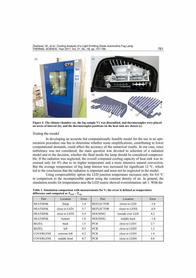
Zadravec, M., et al.: Cooling Analysis of a Light Emitting Diode Automotive Fog Lamp THERMAL SCIENCE, Year 2017, Vol. 21, No. 1B, pp. 757-766 761
Figure 4. The climate chamber (a), the fog sample V1 was dissembled, and thermocouples were placed on areas of interest (b), and the thermocouples positions on the heat sink are shown (c)
Testing the model
In developing an accurate but computationally feasible model for the use in an opti-mization procedure one has to determine whether some simplifications, contributing to lower computational demands, could affect the accuracy of the numerical results. In our case, since turbulence was not considered, the main question was devoted to selection of a radiation model and to the decision, whether the fluid inside the lamp should be considered compressi-ble. If the radiation was neglected, the overall computed cooling capacity of heat sink was in-creased only for 4% due to its higher temperature and a more intensive natural convection. But the average temperature of fog lamp interior was increased for significant 12 °C, which led to the conclusion that the radiation is important and must not be neglected in the model.
Using compressibility option the LED junction temperature increases only for 0.6 °C in comparison to the incompressible option using the constant density of air. In general, the simulation results for temperatures near the LED source showed overestimation, tab 1. With the
Table 1. Simulation comparison with measurements for V; the error is defined as temperature difference and computed as Tnum – Texp
Part Location Error Part Location Error
HEATSINK fintip 1.4 REFLECTOR closer to LED –3.8
HEATSINK close to LED1 5.7 REFLECTOR closer to LENS –6.9
HEATSINK close to LED2 5.4 HOUSING outside over LED 4.2
HEATSINK bottom 1.0 HOUSING middle back –1.0
BEZEL back 1.5 PCB close to LED1 2.7
BEZEL left 0.5 PCB close to LED2 1.2
COVERLENS extreme left 0.2 PCB close to LED3 1.8
COVERLENS middle front 0.7 PCB close to LED4 0.6
Zadravec, M., et al.: Cooling Analysis of a Light Emitting Diode Automotive Fog Lamp 762 THERMAL SCIENCE, Year 2017, Vol. 21, No. 1B, pp. 757-766
used computational grid using the compressibility led to slightly less accurate results. Since the objective of the research is cooling capacity comparison among fin versions, the com-pressibility effect should also vanish when comparing two headlamp fin versions. Next, com-pressible fluid simulation increases central processing unit requirements for 8% which means 5 hours of absolute computing time. Based on this fact, the compressibility effects were ne-glected in all further computations.
A typical computational case was found to be converged when the root-mean square convergence criteria was below 10–6. The numerical solution of the radiation transport equa-tion has the worst domain flux balance fulfilled bellow value of 0.01%. Typical computation-al time was 42 hours using 14 cores of 3 GHz personal computer.
The comparison of simulated and measured temperature is excellent inside of few degrees at all measured points, tab. 1. Larger error is evident at two locations. The first is lo-cation in the upper side of HEATSINK close to the LED. Simulated overestimation for 5 °C is probably due to the contact resistance neglected between PCB and heat sink. If the contact resistance would be simulated the PCB temperatures would be higher and heat sink tempera-tures lower. Another source of this error could be questionable estimation of the radiation emissivity for the heat sink surface. The location close to the LED has the highest temperature and therefore the highest radiation influence. The second error location is reflector surface with simulation underestimation for 7 °C. In our opinion the reason is the same as before. The emissivity coefficient of the polished reflector surface has large influence and it is difficult to measure. The second reason is large deviations in the reflector position in the real lamps. Based on our experimental experience small reflector position difference in the order of mag-nitude of 1 mm produce relative large temperature deviations. Comparing two heat sink ver-sions, which is the aim of the present research, all sources of errors vanished since only rela-tive comparison is made. In this manner and for general purpose the verification of the numer-ical model is concluded as successful.
Results and discussion
Heat sink cooling capacity discussion
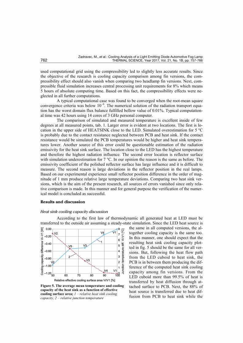
According to the first law of thermodynamic all generated heat at LED must be transferred to the outside air assuming a steady-state simulation. Since the LED heat source is
the same in all computed versions, the al-together cooling capacity is the same too. In this manner, one should expect that the resulting heat sink cooling capacity plot-ted in fig. 5 should be the same for all ver-sions. But, following the heat flow path from the LED cuboid to heat sink, the PCB is in between them producing the dif-ference of the computed heat sink cooling capacity among fin versions. From the LED cuboid more than 99.5% of heat is transferred by heat diffusion through at-tached surface to PCB. Next, the 88% of heat source is transferred due to heat dif-fusion from PCB to heat sink while the
Figure 5. The average mean temperature and cooling capacity of the heat sink as a function of effective cooling surface area; 1 – relative heat sink cooling capacity, 2 – relative junction temperature
Zadravec, M., et al.: Cooling Analysis of a Light Emitting Diode Automotive Fog Lamp THERMAL SCIENCE, Year 2017, Vol. 21, No. 1B, pp. 757-766 763
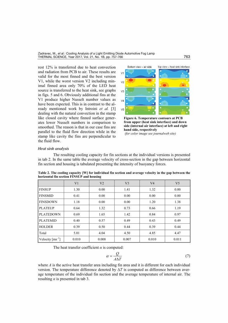
rest 12% is transferred due to heat convection and radiation from PCB to air. These results are valid for the most finned and the best version V1, while the worst version V2 including min-imal finned area only 70% of the LED heat source is transferred to the heat sink, see graphs in figs. 5 and 6. Obviously additional fins at the V1 produce higher Nusselt number values as have been expected. This is in contrast to the al-ready mentioned work by Introini et al. [3] dealing with the natural convection in the stamp like closed cavity where finned surface gener-ates lower Nusselt numbers in comparison to smoothed. The reason is that in our case fins are parallel to the fluid flow direction while in the stamp like cavity the fins are perpendicular to the fluid flow.
Heat sink analysis
The resulting cooling capacity for fin sections at the individual versions is presented in tab 2. In the same table the average velocity of cross-section in the gap between horizontal fin section and housing is tabulated presenting the intensity of buoyancy forces.
Table 2. The cooling capacity [W] for individual fin section and average velocity in the gap between the horizontal fin section FINSUP and housing
The heat transfer coefficient α is computed:
QA T
α =∆
(7)
where A is the active heat transfer area including fin area and it is different for each individual version. The temperature difference denoted by ΔT is computed as difference between aver-age temperature of the individual fin section and the average temperature of internal air. The resulting α is presented in tab 3.
Figure 6. Temperature contours at PCB from upper (heat sink interface) and down side (internal air interface) at left and right hand side, respectively (for color image see journalweb site)
V1 V2 V3 V4 V5
FINSUP 1.30 0.00 1.41 1.32 0.00
FINSMID 0.41 0.00 0.00 0.00 0.00
FINSDOWN 1.18 0.00 0.00 1.20 1.38
PLATEUP 0.64 1.32 0.73 0.66 1.19
PLATEDOWN 0.69 1.65 1.42 0.84 0.97
PLATEMID 0.40 0.57 0.49 0.43 0.49
HOLDER 0.39 0.50 0.44 0.39 0.44
Total 5.01 4.04 4.50 4.85 4.47
Velocity [ms–1] 0.010 0.008 0.007 0.010 0.011
Zadravec, M., et al.: Cooling Analysis of a Light Emitting Diode Automotive Fog Lamp 764 THERMAL SCIENCE, Year 2017, Vol. 21, No. 1B, pp. 757-766
Table 3. Heat transfer coefficient [Wm–2K–1] for the individual fin section and all versions
Heat sink versions discussion
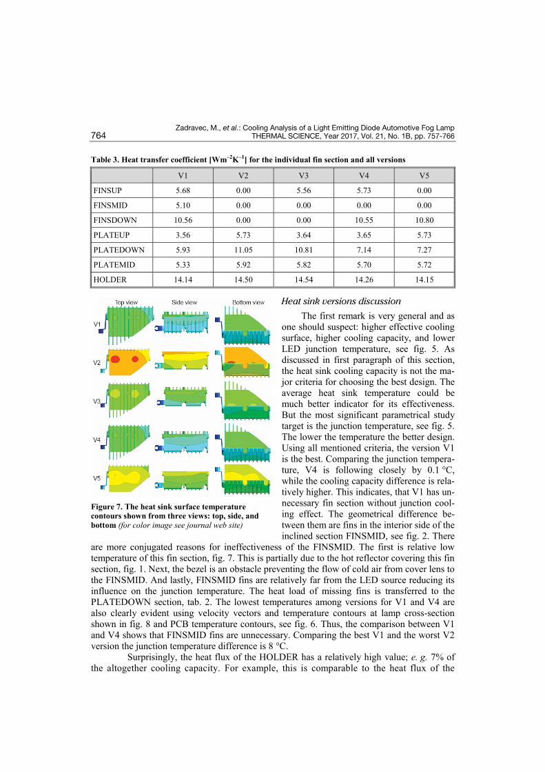
The first remark is very general and as one should suspect: higher effective cooling surface, higher cooling capacity, and lower LED junction temperature, see fig. 5. As discussed in first paragraph of this section, the heat sink cooling capacity is not the ma-jor criteria for choosing the best design. The average heat sink temperature could be much better indicator for its effectiveness. But the most significant parametrical study target is the junction temperature, see fig. 5. The lower the temperature the better design. Using all mentioned criteria, the version V1 is the best. Comparing the junction tempera-ture, V4 is following closely by 0.1 °C, while the cooling capacity difference is rela-tively higher. This indicates, that V1 has un-necessary fin section without junction cool-ing effect. The geometrical difference be-tween them are fins in the interior side of the inclined section FINSMID, see fig. 2. There
are more conjugated reasons for ineffectiveness of the FINSMID. The first is relative low temperature of this fin section, fig. 7. This is partially due to the hot reflector covering this fin section, fig. 1. Next, the bezel is an obstacle preventing the flow of cold air from cover lens to the FINSMID. And lastly, FINSMID fins are relatively far from the LED source reducing its influence on the junction temperature. The heat load of missing fins is transferred to the PLATEDOWN section, tab. 2. The lowest temperatures among versions for V1 and V4 are also clearly evident using velocity vectors and temperature contours at lamp cross-section shown in fig. 8 and PCB temperature contours, see fig. 6. Thus, the comparison between V1 and V4 shows that FINSMID fins are unnecessary. Comparing the best V1 and the worst V2 version the junction temperature difference is 8 °C.
Surprisingly, the heat flux of the HOLDER has a relatively high value; e. g. 7% of the altogether cooling capacity. For example, this is comparable to the heat flux of the
V1 V2 V3 V4 V5
FINSUP 5.68 0.00 5.56 5.73 0.00
FINSMID 5.10 0.00 0.00 0.00 0.00
FINSDOWN 10.56 0.00 0.00 10.55 10.80
PLATEUP 3.56 5.73 3.64 3.65 5.73
PLATEDOWN 5.93 11.05 10.81 7.14 7.27
PLATEMID 5.33 5.92 5.82 5.70 5.72
HOLDER 14.14 14.50 14.54 14.26 14.15
Figure 7. The heat sink surface temperature contours shown from three views: top, side, and bottom (for color image see journal web site)
Zadravec, M., et al.: Cooling Analysis of a Light Emitting Diode Automotive Fog Lamp THERMAL SCIENCE, Year 2017, Vol. 21, No. 1B, pp. 757-766 765
PLATEMID, see tab. 2. The reason for this is in its position, free of the reflector and bezel, in the cold air-flow. On the other hand the fluid flow pattern over the HOLDER rod geometry has the highest heat transfer coefficient, tab. 3.
The second surprise is the highest average velocity in the gap between the heat sink and housing at V5, see tab. 2. Close to the FINSMID section is another spot of large ve-locity vectors at V5, fig. 8. The difference be-tween the best V1 and referenced V5 are miss-ing FINSUP and FINSMID sections. Both fin sections are slowing down the natural convec-tion by increased friction surface area resulting in the highest velocities in V5. As expected the influence of larger active heat transfer surface area prevails over lower velocities and conse-quently lower heat transfer coefficients in the best V1, tab. 3.
The most effective is FINSUP section fol-lowing by the FINSDOWN section. Together they are representing 49% of the total heat sink cooling capacity for V1. The reason is the vi-cinity of cold housing and relative high veloci-ties in the gap between mentioned fins and housing. Computed Reynolds number value based on the maximal velocity and gap dimen-sion is in the range from 10 to 100 clearly indi-cating laminar flow regime.
Heat sink modification proposal
As mentioned before the influence of FINSMID section is minimal since relative slow and hot air in its vicinity. In this manner the material for FINSMID could be better used closer to the LED source. The first place is in the most effective section FINSUP close to the LED. The fins should be prolonged closer to the cold front cover lens and increase the fin height. The second proposition is to extend FINSDOWN also in the direction closer to the front cover to form a nice circulation of a cold air from the front cover lens to the FINSDOWN and FINSMID section. In this manner the gap between heat sink and backside of housing should be increased and smoothed to gain larger velocities. In order to increase ve-locities, the forced convection regime using fan should be considered too.
Conclusion
The numerical simulation of the automotive LED fog lamp is presented in this study. The complex heat transfer mechanism was successfully simulated. The effectiveness of vari-ous fin sections is calculated. The section FINSMID is found to be unnecessary and the prop-osition of its material rearrangement is given. The comparison between measured and simu-
Figure 8. Velocity vectors and temperature contours at the lamp cross-section (for color image see journal web site)
Zadravec, M., et al.: Cooling Analysis of a Light Emitting Diode Automotive Fog Lamp 766 THERMAL SCIENCE, Year 2017, Vol. 21, No. 1B, pp. 757-766
lated temperature is excellent in the range of few degrees. In the future the heat sink modifica-tions will be further analyzed. Next field of research would be the close vicinity of LED where the highest temperatures are present.
References [1] Baumgartner, H., et al., A Temperature Controller for High Power Light Emitting Diodes Based on Re-
sistive Heating and Liquid Cooling, Applied Thermal Engineering, 71 (2014), 1, pp. 317-323 [2] Chih-Neng, H., et al., Heat Transfer and Structure Stress Analysis of Micro Packaging Component of
High Power Light Emitting Diode, Thermal Science, 17 (2013), 5, pp. 1277-1283 [3] Introini, C., et al., Effective Surface Modeling for Momentum and Heat Transfer over Rough Surfaces:
Application to a Natural Convection Problem, International Journal of Heat and Mass Transfer, 54 (2011), 15, pp. 3622-3641
[4] De Vahl Davis, G., Natural Convection of Air in a Square Cavity: A Bench Mark Numerical Solution, International Journal for Numerical Methods in Fluids, 3 (1983), 3, pp. 249-264
[5] Anandan, S. S., Ramalingam, V., Thermal Management of Electronics: A Review of Literature, Thermal Science, 12 (2008), 2, pp. 5-26
[6] Tso, C., et al., Transient and Cyclic Effects on a PCM-Cooled Mobile Device, Thermal Science, 19 (2015), 5, pp. 1723-1731
[7] Christensen, A., Graham, S., Thermal Effects in Packaging High Power Light Emitting Diode Arrays, Applied Thermal Engineering, 29 (2009), 2, pp. 364-371
[8] Sousa, J., et al., An Experimental Investigation of Fluid Flow and Wall Temperature Distributions in an Automotive Headlight, International Journal of Heat and Fluid Flow, 26 (2005), 5, pp. 709-721
[9] Wang, J., et al., Thermal Design and Simulation of Automotive Headlamps Using White Leds, Microe-lectronics Journal, 45 (2014), 2, pp. 249-255
[10] Mielke, C., et al., Simulation of the Temperature Distribution in Automotive Head Lamps, NAFEMS In-ternational Journal of CFD case studies, 9 (2011), June, pp. 23-32
[11] ***, Ansys CFX 15.0: Solver Theory Guide, 2014
Paper submitted: August 29, 2014 © 2017 Society of Thermal Engineers of Serbia. Paper revised: June 9, 2016 Published by the Vinča Institute of Nuclear Sciences, Belgrade, Serbia. Paper accepted: June 9, 2016 This is an open access article distributed under the CC BY-NC-ND 4.0 terms and conditions.