Embed Size (px)
Citation preview

13
Coolant Channel Module CCM. An Universally Applicable
Thermal-Hydraulic Drift-Flux Based Separate-Region Mixture-Fluid Model
Alois Hoeld
Retired from GRS, Garching/Munich Bernaysstr. 16A, D-80937 Munich
F.R. of Germany
1. Introduction
The development of LWR Nuclear Power Plants (NPP) and the question after their safety
behaviour have enhanced the need for adequate theoretical descriptions of these plants.
Thus thermal-hydraulic models and, based on them, effective computer codes played
already very early an important role within the field of NPP safety research. The models and
codes should have the potential to describe the steady state and transient behaviour of
characteristic key parameters of a single- or two-phase fluid flowing along the
corresponding loops of such a plant and thus also along any type of heated or non-heated
coolant channels.
Obviously many discussions have and will continue to take place among experts as to which
type of theoretical approach should be chosen for the correct description of thermal-
hydraulic two-phase problems when looking at the wide range of applications. Very
comprehensive reviews and critical discussions of different possible methods have been
published already very early in the book of Ishii (1990), in the workshop presentations of
Wulff (1987) and by Banerjee and Yadigaroglu (1990). Due to the presence of discontinuities
in the first principle of mass conservation in a two-phase flow model, caused at the
transition from single- to two-phase flow and vice versa, it turns out that the direct solution
of the basic conservation equations for mixture fluid along such a coolant channel gets very
complicated. What is thus the most appropriate way to deal with such a special thermal-
hydraulic problem?
With the introduction of the ‘Separate-Phase Model’ concept it could already very early a
very successful way be shown how to avoid upcoming difficulties in finding solution
methods to treat such a two-phase flow situation under the assumption of separating the
two-phases of such a mixture-flow completely from each other. This yields a system of 4-, 5-
or sometimes even 6-equations defined by splitting each of the conservation equations into
two so-called ‘field equations’. Hence, compared to the four independent parameters
characterising the mixture fluid, the separate-phase systems demand a much higher number
of additional variables and special assumptions. This has the consequence that an enormous
www.intechopen.com

Steam Generator Systems: Operational Reliability and Efficiency
248
amount of CPU-time has to be expended for the solution of the resulting sets of differential
and analytical equations in a computer code. It is clear that, based on such assumptions, the
interfacial relations both between each phase and the (heated or cooled) wall but also
between each of the two phases are completely rearranged, raising the difficult question of
how to describe in a realistic way the direct heat input into and between the phases and the
movement resp. the friction of the phases between them. This problem is solved in such an
approach by introducing corresponding exchange (=closure) terms between the
equations based on special transfer (= closure) laws. Since they can, however, not be
based on fundamental laws or at least on experimental measurements this approach
requires a significant effort to find a correct formulation of the exchange terms between
the phases. It must therefore be recognised that the quality of these basic equations (and
especially their boundary conditions) will be intimately related to the (rather artificial
and possibly speculative) assumptions adopted if comparing them with the original
conservation laws of the 3-equation system and their constitutive equations as well. The
problem of a correct description of the interfacial reaction between the phases and the
wall remains. Hence, very often no consistency between different models due to their
underlying assumptions can be stated. Another problem arises from the fact that special
methods have to be foreseen to describe the moving boiling or mixture level boundaries
(or at least to estimate their ‘condensed’ levels) in such a mixture fluid (see, for example,
the ‘Level Tracking’ method in TRAC). Additionally, these methods show often
deficiencies in describing extreme situations such as the treatment of single- and two-
phase flow at the ceasing of natural circulation, the power situations if decreasing to zero
etc. The codes are sometimes very inflexible, especially if they have to provide to a very
complex physical system also elements which belong not to the usual class of ‘thermal-
hydraulic coolant channels’. These can, for example, be nuclear kinetic considerations,
heat transfer out of a fuel rod or through a tube wall, pressure build-up within a
compartment, time delay during the movement of an enthalpy front along a downcomer,
natural circulation along a closed loop, parallel channels, inner loops etc.
Despite of these difficulties the ‘Separate-Phase Models’ have become increasingly
fashionable and dominant in the last decades of thermal-hydraulics as demonstrated by the
widely-used codes TRAC (Lilles et al.,1988, US-NRC, 2001a), CATHENA (Hanna, 1998),
RELAP (US-NRC,2001b, Shultz,2003), CATHARE (Bestion,1990), ATHLET (Burwell et
al.,1989, Austregesilo et al., 2003, Lerchl et al., 2009).
Several reasons can be named why this method is preferred by many authors and users:
• Advantages due the unique formulation of the up to 6 basic partial differential eqs.
which allows then also to apply a unique mathematical solution method,
• the possibility to circumvent discontinuities (Wulff, 1987) in simulating the transitions
from single- to two-phase flow and vice versa, thus avoiding difficulties in describing
the movement of phase boundaries along a coolant channel,
• avoiding the very difficult direct theoretical treatment of a mixture-fluid approach,
• allowing establishing within the resulting ‘modular’ codes the necessary set of solution
equations (ODE-s and constitutive equations in dependence of corresponding
perturbation parameters) by combining them by means of an adequate input data set,
i.e. outside of the code, with the advantage that the user does not need to be familiar
with the construction of digital codes.
www.intechopen.com

Coolant Channel Module CCM. An Universally Applicable Thermal-Hydraulic Drift-Flux Based Separate-Region Mixture-Fluid Model
249
• giving the possibility to assume further-on that, in the case of two-phase flow situations, the water-phase can adopt temperatures below, the steam phase above saturation conditions. This means, the model can also take care of ‘thermal-hydraulic non-equilibrium’ situations, an important advantage for the application of this class of codes (as this is for example the case if cold water is injected into a steam dome or steam into a sub-cooled water plenum etc.).
It is on the other hand clear that as an alternative for the description of two-phase
phenomena by splitting them into different phases the direct solution of the basic equations
of a mixture-fluid technique could be regarded as a very appropriate approach, provided
that despite of the above mentioned difficulties an exact solution can be found. This direct
method could therefore be seen as a real counterpart to the currently preferred and
dominant ‘separate-phase models’.
However, in the past the difficulties in the direct treatment of a ‘mixture-fluid approach’
have been responsible for the fact that only approximate and very simplified solutions for
special situations could be provided, thus demanding severe restrictions in their field of
application. As pointed-out by (Fabic, 1996) in the early seventies such simplified
‘homogenous equilibrium models (HEM-s)’ have been derived under the assumption of a
homogeneous fluid, a mixture where water and steam phase are assumed to move with the
same velocity, i.e. the slip remains equal to 1 and the relative and thus also drift velocities
equal to 0. Since for most purposes this is too far from reality, it is obvious that such
simplified ‘homogeneous’ approaches (see for example Dunn, 1998) could only be applied
to special cases, for example where the speed of the calculation has to be enhanced in order
to be usefully applied in comprehensive two-phase flow studies. Their shortcomings are
mainly responsible for the seemingly widespread misunderstanding of the quality of
‘mixture-fluid’ models, their poor image and the subsequent unfair treatment of this class of
models.
Zuber et al. (1965) and Wulff (1987) proposed already very early a concept called (a bit
imprecisely) ‘drift-flux model’ which has been continuously expanded according to the
rising demands in reactor safety research. In fact it is a ‘four-equation non-homogeneous
non-equilibrium two-phase flow model’ with mass-, energy- and momentum balances for
the mixture and a separate mass balance for the vapour phase based on a specially
developed ‘drift-flux theory’. It has been successfully applied in a number of post-
calculations of reactor transients (with up to ten times real-times simulation speed)
including BWR instability simulations with large power and flow oscillations.
At the Gesellschaft für Anlagen- und Reaktorsicherheit (GRS) at Garching/Munich very
early activities have been started too to develop thermal-hydraulic models and digital codes
which have the potential to describe in a detailed way the overall transient and accidental
behaviour of fluids flowing along the core but also the main components of different
Nuclear Power Plants (NPP) types. For one of these components, namely the natural
circulation U-tube steam generator together with its main steam system, an own theoretical
model has been derived. The resulting digital code UTSG (Hoeld, 1978) could be used both
in a stand-alone way but also as part of more comprehensive transient codes, such as the
thermal-hydraulic GRS system code ATHLET (Burwell et al., Austregesilo, 2003) with an
high level simulation language GCSM (General Control Simulation Module) to take care of
the balance-of-plant (BOP) actions. Based on the experience of many years of application
both at the GRS and a number of other institutes in different countries but also due to the
www.intechopen.com

Steam Generator Systems: Operational Reliability and Efficiency
250
rising demands coming from the safety-related research studies this UTSG theory and code
has been continuously extended, yielding finally a very satisfactory and mature code
version UTSG-2 (Hoeld, 1990a).
During the research work for the development of the code UTSG-2 it arose finally the idea to
establish an own basic element which is able to simulate the thermal-hydraulic mixture-
fluid situation within any type of cooled or heated channel in an as general as possible way,
having the aim to be applicable for any modular construction of complex thermal-hydraulic
assemblies of pipes and junctions. Thereby, as described in detail in this paper, in contrast to
the above mentioned class of ‘separate-phase’ modular codes instead of separating the
phases of a mixture fluid within the entire coolant channel an alternative theoretical
approach has been chosen, differing both in its form of application but also in its theoretical
background. To circumvent the above mentioned difficulties due to discontinuities resulting
from the spatial discretization of a coolant channel, resulting eventually in nodes with a
transition from single- to two-phase flow and vice versa, a special and unique concept has
been derived assuming that a (basic) coolant channel (BC) should be subdivided into a
number of sub-channels (SC-s) with the imposition that each of these SC-s can consist of
only two types of flow regimes, an SC with just a single-phase fluid, containing exclusively
either sub-cooled water (setting LFTYPE=1) or superheated steam (LFTYPE=2), or an SC with a
two-phase mixture (LFTYPE=0). The theoretical considerations of this ‘separate-region
approach’ (within the class of mixture-fluid models) can then be restricted to only these two
regimes. Hence, for each SC type, the ‘classical’ 3 conservation equations for mass, energy
and momentum can be treated in a direct way. In case of a sub-channel with mixture flow
these basic equations have to be supported by a drift flux correlation yielding an additional
relation for the appearing fourth variable, namely the steam mass flow. This can, eventually,
be achieved by any two-phase correlation (for example also a slip correlation). But, to take
care also of stagnant or counter-current flow situations, an effective drift-flux correlation
seems to be more effective. For separate-phase models no such direct experimentally based
correlations are available. It has to be noted that, different to the ‘drift-flux model’ where a
4-th mass balance equation for the vapour phase is introduced, the fundamental mixture-
fluid equations are based on an adequate drift-flux correlation in an analytical form.
It is obvious that this procedure has, however, the consequence that varying SC entrance
and outlet boundaries have to be considered too. As demonstrated in this paper an adequate
way to solve this essential problem could be found and a corresponding procedure been
established. As a result of these theoretical considerations an universally applicable 1D thermal-hydraulic drift-flux based separate-region coolant channel module (and code) CCM could be constructed. Its aim is to make it possible to calculate automatically the steady state and transient behaviour of all characteristic parameters of a single- and two-phase fluid within the entire coolant channel. It represents thus a valuable tool for the establishment of complex codes and can contribute even in the case of complex thermal-hydraulic systems which may consist of a number of different types of (basic) coolant channels to the overall set of equations by determining automatically the different differential and constitutive equations needed for each of these sub- and thus basic channels. To check the performance and validity of the code package CCM, to verify and validate it (see Hoeld, 1978, 1990b, 2002a, 2007a, 2007b) the digital code UTSG-2 has been extended to a new version, called UTSG-3. It is based, similarly as in the previous code UTSG-2, on the
www.intechopen.com

Coolant Channel Module CCM. An Universally Applicable Thermal-Hydraulic Drift-Flux Based Separate-Region Mixture-Fluid Model
251
same U-tube, main steam and downcomer (with feedwater injection) system layout, but now, among other essential improvements, the three characteristic channel elements of the code UTSG-2 (i.e. the primary and secondary side of the heat exchange region and the riser region) have been replaced by adequate CCM modules. Naturally, during the application of UTSG-3 and thus CCM both codes have been continuously expanded to a now very mature form (Hoeld, 1998b, 1999, 2000). It is obvious that such a theoretical ‘separate-region’ approach can disclose a new way in
describing thermal-hydraulic problems, regarding the resulting ‘mixture-fluid’ technique as
a very appropriate way to circumvent the uncertainties apparent from the separation of the
phases in a mixture flow. The starting equations are the direct consequence of the original
fundamental physical laws for the conservation of mass, energy and momentum, supported
by well-tested heat transfer and single- and two-phase friction correlation packages (and
thus avoiding also the sometimes very speculative derivation of the ‘closure’ terms). In a
very comprehensive study by (Hoeld, 2004b) a variety of arguments for the here presented
type of approach is given, some of which will be discussed in the conclusions presented in
chapter 6.
The very successful application of the code combination UTSG-3/CCM demonstrates the
ability to find an exact and direct solution for the basic equations of a 'non-homogeneous
drift-flux based thermal-hydraulic mixture-fluid coolant channel model’. The theoretical
background of CCM will be described in very detail in the following chapters.
For the establishment of the corresponding (digital) module CCM, based on this theoretical
model and written in double-precision (with its single-precision version CCMS) very
specific methods had to be achieved, thereby taking into account the following points:
• The code should be easily applicable, demanding only a limited amount of easily available input data. It should also be able to simulate the thermal-hydraulic mixture-fluid situation along any cooled or heated channel in as general a way as possible. It should thus be able to describe any modular construction of complex thermal-hydraulic assemblies of pipes and junctions. Such an universally applicable tool can then be taken for calculating the steady state and transient behaviour of all the characteristic parameters of each of the appearing coolant channels and thus be a valuable element for the construction of complex computer codes. It should yield as output all the necessary time-derivatives and constitutive parameters of the coolant channels required for the establishment of an overall thermal-hydraulic code.
• It was the intention of CCM that it should act as a complete system in its own right,
requiring only BC- (and not SC-) related, and thus easily available input parameters
(geometry data, initial and boundary conditions, parameters resulting from the
integration etc.). The partitioning of BC-s into SC-s is done at the begin of each
recursion or time-step automatically within CCM, so no special actions are required of
the user.
• Knowing now the characteristic parameters at all SC nodes (within a BC) then the
single- and two-phase parameters at all node boundaries of the entire BC can be
determined, but also also the corresponding time-derivatives of the averaged
parameters over these nodes. This yields a final set of ODE-s and constitutive equations.
• The quality of such a model is very much dependent on the method by which the
problem of the varying SC entrance and outlet boundaries can be solved, especially if
they cross BC node boundaries during their movement along a channel. Hence, on the
www.intechopen.com

Steam Generator Systems: Operational Reliability and Efficiency
252
basis of the ‘Leibniz’ rule (see eq.(29)), special measures had to be developed which
allow the characterisation of their transient behaviour in deriving own differential
equations.
• For the support of the nodalized differential equations along different SC-s a ‘quadratic
polygon approximation’ procedure (PAX) was constructed in order to interrelate the
mean nodal with the nodal boundary functions. Additionally, due to the possibility of
varying SC entrance and outlet boundaries, nodal entrance gradients are also required
from the PAX procedure too (See section 3.3).
• Several correlation packages such as, for example, packages for the thermodynamic properties of water and steam, heat transfer coefficients, drift flux correlations and single- and two-phase friction coefficients had to be established and implemented (See sections 2.2.1 to 2.2.4).
• It order to be able to describe also thermodynamic non-equilibrium situations it can be assumed that each phase is described by an own with each other interacting BC. Then, in the model the possibility of a variable cross flow area along the entire channel had to be considered as well.
Within the CCM procedure two further aspects play an important role These are, however,
not essential for the development of mixture-fluid models but can help enormously to
enhance the computational speed and applicability of the resulting code in simulating a
complex net of coolant pipes:
• Solution of energy and mass balance equations during each intermediate time step independently from momentum balance considerations in order to avoid the heavy CPU-time consuming solution of stiff equations (See section 3.5).
• This allows then also the introduction of an ‘open’ and ‘closed channel’ concept (see section 3.11), a special method which can be very helpful in describing complex physical systems with eventually inner loops, as this can be done for example if simulating a 3D compartment by parallel channels (Jewer et al., 2005).
The application of a direct mixture-fluid technique follows a long tradition of research
efforts. Ishii (1990), a pioneer of two-fluid modelling, states with respect to the application of
effective drift-flux correlation packages in thermal-hydraulic models: ‘In view of the limited
data base presently available and difficulties associated with detailed measurements in two-
phase flow, an advanced mixture-fluid model is probably the most reliable and accurate tool
for standard two-phase flow problems’. There is no new knowledge available to indicate
that this view is invalid.
Generally, the mixture-fluid approach is in line with (Fabic, 1996) who names three strong points arguing in favour of this type of drift-flux based mixture-fluid models:
• They are supported by a wealth of test data,
• they do not require unknown or untested closure relations concerning mass, energy and momentum exchange between phases (thus influencing the reliability of the codes),
• they are much simpler to apply, and, it can be added,
• discontinuities during phase changes can be avoided by deriving special solution procedures for the simulation of the movement of these phase boundaries,
• the possibility to circumvent a set of ‘stiff’ ODE-s saves an enormous amount of CPU time which means that the other parts of the code can be treated in much more detail.
www.intechopen.com

Coolant Channel Module CCM. An Universally Applicable Thermal-Hydraulic Drift-Flux Based Separate-Region Mixture-Fluid Model
253
A first version of the module CCM has already been presented in October 2005 at the
NURETH-11 conference at Avignon (Hoeld, 2005), a corresponding detailed version
published then in (Hoeld, 2007a). Due to the rising experiences in applying this module it
has been continuously adapted during the last years resulting in the here presented final
form. The theoretical model and module CCM has the potential to be extended, in a second phase, to a 'porous' coolant channel model too, porous at each node boundary, i.e. to the more detailed case where coolant mass (water, steam and/or water/steam mixtures) is exchanged also at nodal boundaries between neighbouring channels (and not only at BC entrance or outlet). Parallel to this paper in a second article within this 'Open Access Book' a detailed description of the last status of the resulting 'Natural-circulation U-tube Steam Generator' Code UTSG-3 (including main steam and feedwater systems) is given by (Hoeld, 2011). It demonstrates the ability to apply the 'Coolant Channel Module CCM' as an important element in a complex system of loops and branches in a successful way.
2. Thermal-hydraulic drift-flux based mixture fluid approach
2.1 Thermal-hydraulic conservation equations
Thermal-hydraulic single-phase or mixture-fluid models for coolant channels or, as presented here, for each of the sub-channels are generally based on a number of fundamental physical laws, i.e. on genuine conservation equations for mass, energy and momentum. They are supported by adequate constitutive equations (packages for thermo-dynamic and transport properties of water and steam, for heat transfer coefficients, for drift flux, for single- and two-phase friction coefficients etc.). Thereby second-order terms (representing, for example, dissipation in flow direction, drag and gravitational work) are frequently found to be quantitatively insignificant (Wulff, 1987) and will thus not be taken into account. In view of possible applications as an element in complex thermal-hydraulic ensembles outside of CCM eventually a fourth and fifth conservation law has to be considered too. The equation for volume balance makes it possible to calculate for example the transient behaviour of the overall system pressure. Together with the local pressure differences then the absolute pressure profile along the BC can be determined. The fifth physical law is based on the (trivial) fact that the sum of all pressure decrease terms along a closed loop must be zero. It is the basis for the treatment of the thermal-hydraulics of a channel according on ‘the closed channel concept’. If thus such a channel acts as a part of a closed loop (with given fixed BC entrance and outlet pressure terms) then the necessary entrance mass flow term has be determined in order to fulfil the demand from momentum balance.
2.1.1 Mass balance (for both single- and two-phase flow)
t
∂∂ {A[(1-α)ρW+αρS]}+z∂∂ G=0 (1)
containing the density terms ρW and ρS for sub-cooled or saturated water and saturated or
superheated steam, the void fraction α and the cross flow area A which can eventually be changing along the coolant channel. It determines, after a nodalization, the total mass flow G=GW+GS at node outlet in dependence of its node entrance value.
www.intechopen.com
Steam Generator Systems: Operational Reliability and Efficiency
254
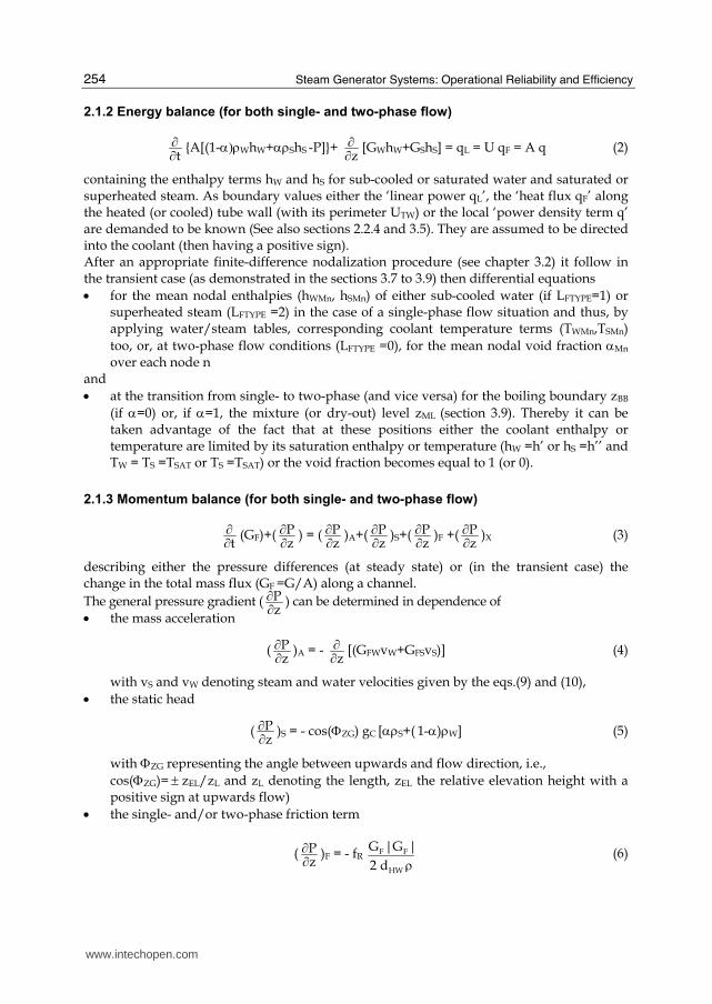
2.1.2 Energy balance (for both single- and two-phase flow)
t
∂∂ {A[(1-α)ρWhW+αρShS -P]}+ z
∂∂ [GWhW+GShS] = qL = U qF = A q (2)
containing the enthalpy terms hW and hS for sub-cooled or saturated water and saturated or superheated steam. As boundary values either the ‘linear power qL’, the ‘heat flux qF’ along the heated (or cooled) tube wall (with its perimeter UTW) or the local ‘power density term q’ are demanded to be known (See also sections 2.2.4 and 3.5). They are assumed to be directed into the coolant (then having a positive sign). After an appropriate finite-difference nodalization procedure (see chapter 3.2) it follow in the transient case (as demonstrated in the sections 3.7 to 3.9) then differential equations
• for the mean nodal enthalpies (hWMn, hSMn) of either sub-cooled water (if LFTYPE=1) or superheated steam (LFTYPE =2) in the case of a single-phase flow situation and thus, by applying water/steam tables, corresponding coolant temperature terms (TWMn,TSMn)
too, or, at two-phase flow conditions (LFTYPE =0), for the mean nodal void fraction αMn over each node n
and
• at the transition from single- to two-phase (and vice versa) for the boiling boundary zBB
(if α=0) or, if α=1, the mixture (or dry-out) level zML (section 3.9). Thereby it can be taken advantage of the fact that at these positions either the coolant enthalpy or temperature are limited by its saturation enthalpy or temperature (hW =h’ or hS =h’’ and TW = TS =TSAT or TS =TSAT) or the void fraction becomes equal to 1 (or 0).
2.1.3 Momentum balance (for both single- and two-phase flow)
t
∂∂ (GF)+( Pz
∂∂ ) = ( Pz
∂∂ )A+( Pz
∂∂ )S+( Pz
∂∂ )F +( Pz
∂∂ )X (3)
describing either the pressure differences (at steady state) or (in the transient case) the change in the total mass flux (GF =G/A) along a channel.
The general pressure gradient ( Pz
∂∂ ) can be determined in dependence of
• the mass acceleration
( Pz
∂∂ )A = - z∂∂ [(GFWvW+GFSvS)] (4)
with vS and vW denoting steam and water velocities given by the eqs.(9) and (10),
• the static head
( Pz
∂∂ )S = - cos(ΦZG) gC [αρS+( 1-α)ρW] (5)
with ΦZG representing the angle between upwards and flow direction, i.e.,
cos(ΦZG)= ± zEL/zL and zL denoting the length, zEL the relative elevation height with a positive sign at upwards flow)
• the single- and/or two-phase friction term
( Pz
∂∂ )F = - fR F F
HW
G |G |
2 d ρ (6)
www.intechopen.com

Coolant Channel Module CCM. An Universally Applicable Thermal-Hydraulic Drift-Flux Based Separate-Region Mixture-Fluid Model
255
with a friction factor derived from corresponding constitutive equations (section 2.2.2) and finally
• the direct perturbations ( )z/P ∂∂ X from outside, arising either by starting an external
pump or considering a pressure adjustment due to mass exchange between parallel
channel.
2.2 Constitutive equations
For the exact description of the steady state and transient behaviour of single- or two-phase
fluids there are needed, besides the conservation equations, a number of mostly empirical
constitutive relations. Naturally, any effective correlation package can be used for this
purpose. A number of such correlations have been developed at the GRS and thoroughly
tested, showing very satisfactory results.
2.2.1 Thermopdynamic and transport properties of water and steam
The different thermodynamic and transport properties for water and steam demanded by
the conservation and constitutive equations have to be determined by applying adequate
water/steam tables. This is, for light-water systems, realized in the code package MPP
(Hoeld, 1996). It yields the wanted values such as the saturation temperature TSAT, densities
(ρ/, ρ//), enthalpies (h/, h//) for saturated water and steam with respect to their local pressure
(P) and corresponding densities (ρ) and enthalpies (h) for sub-cooled water or superheated
steam (index W and S) again with respect to their independent local parameters T and P (but
also h and P).
For the solution of the conservation equations also time-derivatives of these thermodynamic
properties which respect to their independent local parameters are demanded. They get, for
example for the case of an enthalpy term h, the form
ddt
h(z,t) = ddt
h[T(z,t),P(z,t)] = ( hT
∂∂ ) ddt
TMn(t) + ( hP
∂∂ )Mn ddt
PMn(t)
= hT ddt
TMn(z,t) + hPddt PMn(z,t) (7)
Hence the thermodynamic water/steam tables should provide also the derivatives (T PSAT ,
ρ’P, ρ//P, h’P, h’’P) for saturated water and saturated steam but also the partial derivatives (ρT,
ρP, cP = hT, hP) for subcooled water or superheated steam with respect to their independent
parameters T and P (but also h and P). Additionally, corresponding thermodynamic
transport properties such as ‘dynamic viscosity’ and ‘thermal heat conductivity’ (and thus
the ‘Prantl number’) are asked from some constitutive equations too as this can be stated, for
example, for the code packages MPPWS and MPPETA (Hoeld, 1996). All of them have been
derived on the basis of tables given by (Schmidt and Grigull, 1982) and (Haar et al., 1988). Obviously, the CCM method is also applicable for other coolant systems (heavy water, gas)
if adequate thermodynamic tables for this type of fluids are available.
2.2.2 Single- and two-phase friction factors
In the case of single-phase flow with regard to equation (6) the friction factor fR will, as
recommended by (Moody, 1994), be set equal to the Darcy-Weisbach single-phase friction
factor fDW being represented by
www.intechopen.com

Steam Generator Systems: Operational Reliability and Efficiency
256
fR = fDW = 2
1ξ (at single-phase flow) (8)
with the parameter ξ depending on the Reynolds number Re = G dH/(A η ) and the relative
roughness εTW/dH of the wall surface. The factor ξ can be approximated by the relation
ξ = 2 log10( H
TW
d
ε ) + 1.14 if Re > ReCTB = 441.19 ( H
TW
d
ε ) 1.1772
= - 2 log10 (2.51 Reξ
+ TW
H3.71d
ε) if Re ≤ ReCTB (9)
For two-phase flow conditions this factor can be extended to
fR = fDW Φ 22PF (at two-phase flow) (10)
with the single-phase part fDW to be determined under the assumption that the fluid moves
with the total mass flow G (= 100 % liquid flow). The two-phase multiplier Φ 22PF (dependent
only on steam quality and pressure) is given by (Martinelli-Nelson, 1948) as measured
curves. A possible attempt to describe these curves analytically could, as proposed by
(Hoeld, 1990a, 2004a), be given by the approximation function
Φ 22PF = exp 1
22 3
f X
1 f X f X+ + → /
//
ρρ WD S
WD W
(f )
(f ) if X → 1 (11)
with the factors
f1 = 44.216 + 0.7428 10-6 P f2 = 12.645 + 4.9841 10-6 P
f3 = 17.975 +25.7440 10-6 P (P in Pa) (12)
For the special case of a steam quality X nearing 1 the friction term has to approach the single-phase steam friction factor (fDW)S. Thus the two-phase multiplier has, as shown above, to be corrected in an appropriate way (for example, by changing the curve after a maximum of X at about 0.8).
2.2.3 Drift flux correlation
In the case of two-phase flow, the three conservation equations (1), (2) and (3) demanding
four independent variables (G, α, P and GS) have to be completed by an additional two-phase relation in order to obtain an adequate representation of the needed fourth variable GS. This can be achieved by any two-phase correlation, e.g. also a slip correlation. However, to take care of stagnant or counter-current flow situations too an effective drift-flux correlation seemed here to be more appropriate, correlations which can be seen as a ‘bridge’
between GS and α. For this purpose an own drift-flux correlation package has been established, named MDS (Hoeld, 2001 and 2002a). It is based on the result of a very comprehensive study (Hoeld et al., 1992) and (Hoeld, 1994) comparing different slip (6) and drift-flux (3) correlations with each other and also with a number (5) of available experimental data in order to check their validity over a wide range of application. Besides them, it had to be found which of them is
www.intechopen.com

Coolant Channel Module CCM. An Universally Applicable Thermal-Hydraulic Drift-Flux Based Separate-Region Mixture-Fluid Model
257
most suited for incorporation into the MDS package and thus CCM code. Due to different requirements in the application of CCM it turned out that the drift-flux correlation package in the form of the ‘flooding-based full-range’ Sonnenburg correlation (1989) should be preferred. This correlation combines the common drift-flux procedure being formulated by (Zuber-Findlay, 1965) and expanded by (Ishii-Mishima, 1980) and (Ishii, 1990) etc. with the modern envelope theory. The correlation in the final package MDS had
to be rearranged in such a way that also the special cases of α → 0 or α → 1 (where its
absolute values but also their gradients are demanded by CCM) could be treated. Additionally, an inverse form had to be installed and considerations with respect to a possible entrainment be included. For the case of a vertical channel this correlation can be represented as
vD = 1.5 vWLIM C0CVD [(1+CVD2) 3/2 − (1.5+CVD2) CVD]
with vD → vD0 =916
C0vWLIM if α → 0 (13)
where the coefficient CVD is given by
CVD = 23
SLIM
WLIM
v
v0
0
1 C
C
− αα (14)
The resulting package MDS yields in combination with an adequate correlation for the
phase distribution parameter C0 relations for the limit velocities vSLIM and vWLIM and thus
(independently of the total mass flow G) for the drift velocity vD in relation to the void
fraction α. All of them are dependent on the given 'system pressure P', the 'hydraulic
diameter dHW' (with respect to the wetted surface AWSF) and its inclination angle ΦZG), on
specifications about the geometry type (LGTYPE) and, for low void fractions, the information
whether the channel is heated or not.
The drift flux theory can be expressed (by a now already on G dependent) steam mass flow
term
GS = //
/
ρρ GCC
α(C0G+Aρ/vD) = AGFS (15)
with the coefficient
CGC = 1− (1− //
/
ρρ ) αC0 → 1 if α → 0 and →
//
/
ρρ if α → 1 (16)
by considering the definition equations of the velocities for steam, water and drift
vD = (1−αC0) vS − (1−α) C0vW (17)
vS = S//
G
Aαρ with GS = G - GW = XG (18)
vW = W/
G
A(1 )− α ρ with GW = (1-X) G (19)
www.intechopen.com
Steam Generator Systems: Operational Reliability and Efficiency
258
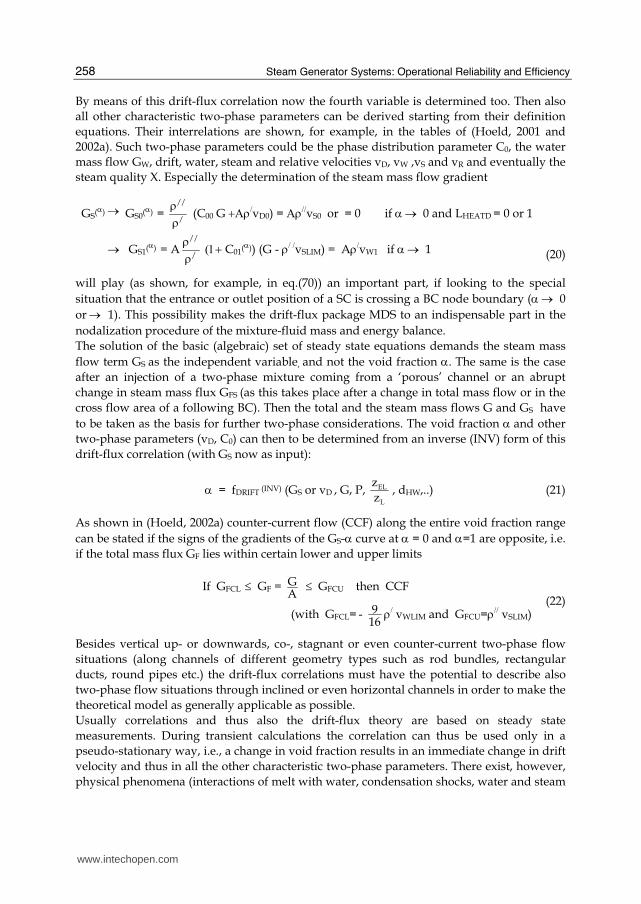
By means of this drift-flux correlation now the fourth variable is determined too. Then also
all other characteristic two-phase parameters can be derived starting from their definition
equations. Their interrelations are shown, for example, in the tables of (Hoeld, 2001 and
2002a). Such two-phase parameters could be the phase distribution parameter C0, the water
mass flow GW, drift, water, steam and relative velocities vD, vW ,vS and vR and eventually the
steam quality X. Especially the determination of the steam mass flow gradient
GS(α) → GS0(α) = //
/
ρρ (C00 G +Αρ/vD0) = Αρ//vS0 or = 0 if α → 0 and LHEATD = 0 or 1
→ GS1(α) = A //
/
ρρ (1+ C01(α)) (G - ρ/ /vSLIM) = Aρ/vW1 if α → 1 (20)
will play (as shown, for example, in eq.(70)) an important part, if looking to the special
situation that the entrance or outlet position of a SC is crossing a BC node boundary (α → 0
or → 1). This possibility makes the drift-flux package MDS to an indispensable part in the
nodalization procedure of the mixture-fluid mass and energy balance.
The solution of the basic (algebraic) set of steady state equations demands the steam mass
flow term GS as the independent variable, and not the void fraction α. The same is the case
after an injection of a two-phase mixture coming from a ‘porous’ channel or an abrupt
change in steam mass flux GFS (as this takes place after a change in total mass flow or in the
cross flow area of a following BC). Then the total and the steam mass flows G and GS have
to be taken as the basis for further two-phase considerations. The void fraction α and other
two-phase parameters (vD, C0) can then to be determined from an inverse (INV) form of this
drift-flux correlation (with GS now as input):
α = fDRIFT (INV) (GS or vD , G, P, EL
L
z
z, dHW,..) (21)
As shown in (Hoeld, 2002a) counter-current flow (CCF) along the entire void fraction range
can be stated if the signs of the gradients of the GS-α curve at α = 0 and α=1 are opposite, i.e.
if the total mass flux GF lies within certain lower and upper limits
If GFCL ≤ GF = GA
≤ GFCU then CCF
(with GFCL= - 916
ρ/ vWLIM and GFCU=ρ// vSLIM) (22)
Besides vertical up- or downwards, co-, stagnant or even counter-current two-phase flow
situations (along channels of different geometry types such as rod bundles, rectangular
ducts, round pipes etc.) the drift-flux correlations must have the potential to describe also
two-phase flow situations through inclined or even horizontal channels in order to make the
theoretical model as generally applicable as possible.
Usually correlations and thus also the drift-flux theory are based on steady state
measurements. During transient calculations the correlation can thus be used only in a
pseudo-stationary way, i.e., a change in void fraction results in an immediate change in drift
velocity and thus in all the other characteristic two-phase parameters. There exist, however,
physical phenomena (interactions of melt with water, condensation shocks, water and steam
www.intechopen.com

Coolant Channel Module CCM. An Universally Applicable Thermal-Hydraulic Drift-Flux Based Separate-Region Mixture-Fluid Model
259
hammer) where the delay between relative velocity and void fraction has a special
importance, also if this delay lays within a range of 0.01 to 0.1 s. In the ‘drift flux model’ this
is taken care by the fourth mass balance equation for the steam, in the separate-phase
models by the (time-dependent) exchange term within the mass balance equations for the
two phases water and steam. To cover thus in this approach also such transient phenomena
the drift-flux considerations can be extended by providing the drift velocity vD with respect
to the void fraction with a corresponding time-delay function of 1-st order. Then the original
(pseudo-steady state) drift velocity parameter vD = vDPSE has to be expanded to its transient
counter-part
vD = vDPSE - (vDPSE - vDB ) exp(- B
VDT
t t−Θ ) (23)
with vDB = vD at the begin of a time interval t = tB. All the other two-phase parameters are then calculated accordingly. The disadvantage of not directly knowing the time coefficient
ΘVDT is outweighed by the advantage of having a direct and controlled input coefficient, avoiding thus the uncertainties of the sometimes very complex separate-phase theory. There exist different possibilities to determine indirectly this coefficient, either from similar theoretical considerations as performed to establish the exchange terms, from experience or from adequate parameter studies.
2.2.4 Heat transfer coefficients
As input to the energy balance eq.(2) the linear power value qL (or the corresponding heat
flux qF along the perimeter UTW) are demanded. They describe the heat transferred into or
out of the coolant channel), i.e. from a heated or cooled surface (for example from or into a
U-tube wall or out of the canning of a fuel rod). These terms (but also the local surface
temperature TTW of the channel wall) can be determined by solving an adequate Fourier
heat conduction equation with its boundary condition
qF = αTW (TTW -T) = U
q L = U
Aq (24)
This is, for example, demonstrated for the case of heat conduction through a U-tube wall in
(Hoeld, 2002b, 2011).
Hence, a method how to get the necessary heat transfer coefficients αTW at different flow regimes within a coolant channel had to be established. In connection with the development of the UTSG code (and thus also of CCM) an own very comprehensive heat transfer coefficient package, called HETRAC (Hoeld 1988a), has been established. It combines, for example, especially for this purpose chosen HTC correlations for each possible flow situation within LWR-s and steam generators (i.e., into or out of heated or cooled tube walls or fuel elements) in a very effective way. Thereby adequate correlations for the cases of sub-cooled water, sub-cooled and nucleate boiling, onset of critical heat flux, transient or instable film boiling, stable film boiling, onset of superheating and superheated steam for different geometry constellations and over a wide range of input parameters (pressures, total and steam mass flows, coolant temperatures, wall temperatures or heat fluxes etc.) had to be selected. The package describes not only heat transfer from wall to the different phases but also between these phases.
www.intechopen.com

Steam Generator Systems: Operational Reliability and Efficiency
260
This classic method is different to the ‘separate-phase’ models where it must be assumed that the heat is transferred both directly from the wall to each of the two possible phases but also exchanged between them. There arises then the question how the corresponding heat transfer coefficients for each phase should look like.
3. Coolant channel module CCM
3.1 Channel geometry and finite-difference nodalization
The theoretical considerations take advantage of the fact that, as sketched in fig.1, a ‘basic’
coolant channel (BC) can, according to their flow regimes (characterized by the logical LFTYPE
Fig. 1. Subdivision of a ‘basic channel’ into ‘sub-channels’ according to their flow regimes. Discretization of BC and SC-s
= 0, 1 or 2), be subdivided into a number (NSCT) of sub-channels (SC-s,), with the consequence of having variable entrance and outlet positions.
The BC with its total length zBT = zBA-zBE can then, for discretization purposes, be
subdivided into a number of (not necessarily equidistant) NBT nodes. Their nodal positions
are zBE, zBk (with k=1,NBT), the elevation heights zELBE, zELk, the nodal length ΔzBk=zBk-zBk-1,
nodal elevations ΔzELBk=zELBk-zELBk-1, locally varying cross flow and average areas ABk and
ABMk=0.5(ABk+ABk-1) with the slopes A zBk
= (ABk-ABk-1)/ΔzBk and corresponding nodal
volumes VBMk = ΔzBkABMk. All of them can be assumed to be known from input. As a consequence, each of the sub-channels (SC-s) is then subdivided too, now into a
number of NCT SC nodes with geometry data being identical to the corresponding BC
values, except, of course, at their entrance and outlet positions. The SC entrance position zCE
www.intechopen.com

Coolant Channel Module CCM. An Universally Applicable Thermal-Hydraulic Drift-Flux Based Separate-Region Mixture-Fluid Model
261
and their function fCE are either identical with the BC entrance values zBE and fBE or equal to
the outlet values of the SC before. The SC outlet position (zCA) is either limited by the BC
outlet (zBA) or characterized by the fact that the corresponding outlet function has reached
an upper or lower limit (fLIMCA), with the term representing either a function at the boiling
boundary or a mixture level. Such a function follows from the given BC limit values and
will, in the case of single-phase flow, be equal to the saturation temperature TSATCA or
saturation enthalpies (h/ or h// if LFTYPE=1 or 2), in the case of two-phase flow (LFTYPE=0) equal
to a void fraction of α = 1 or = 0. The moving SC inlet and outlet positions zCE and zCA can
(together with their corresponding BC nodes NBCE and NBCA = NBCE+NCT) be determined
according to the conditions (zBNk-1 < zCE < zBNk at k = NBCE) and (zBNk-1 < zCA < zBNk at k =
NBCA). Then also the total number of SC nodes (NCT=NBCA-NBCE) is given, the connection
between n and k (n=k-NBCE with n=1, NCT), the corresponding positions (zNn, zELCE, zELNn),
their lengths (ΔzNn=zNn-zNn-1), elevations (ΔzELNn=zELNn-zELNn-1), and volumes (VMn=zNnAMn)
and nodal boundary and mean nodal flow areas (ANn, AMn) with
ANn = ANn-1 + A zBk
Nn
Bk
z
z
ΔΔ
AMn = 0.5(ANn+ANn-1) = ANn-1 + 0.5 A zBk
Nn
Bk
z
z
ΔΔ (n=1,NCT, k=n +NBCE) (25)
Hence, also their time-derivatives and that of the nodal volumes can be ascertained from the
relations above.
3.2 Spatial discretization of PDE-s of 1-st order (Modified finite element method)
Based on this nodalization the spatial discretization of the fundamental eqs.(1) to (3) can be
performed by means of a ’modified finite element method’. This means that if a partial
differential equation (PDE) of 1-st order having the general form with respect to a general
solution function f(z,t)
t
∂∂ f(z,t) +z
∂∂ H[f(z,t)] = R[f(z,t)] (26)
is integrated over the length of a SC node three types of discretization elements can be
expected:
• Integrating a function f(z,t) over a SC node n yields the nodal mean function values fMn
Nn
Nn 1
z (t )
z (t)−∫ R[f(z,t)}dz =ΔzNn(t) R[fMn t)] (n=1, NCT) (27)
• integrating over the gradient of the function yields to a difference of functions values at their node boundaries
Nn
Nn 1
z (t )
z (t ) z−∂∫ ∂ H[f(z,t)]dz = H[fNn(t)] – H[fNn-1(t)] (n=1, NCT) (28)
• and finally the integration over a time-derivative of a function (by applying the 'Leibniz' rule)
www.intechopen.com

Steam Generator Systems: Operational Reliability and Efficiency
262
Nn
Nn 1
z (t )
z (t) t−∂∫ ∂ f(z,t)dz = ΔzNn(t) d
dtfMn(t) -[fNn(t) -fMn(t)] d
dtzNn(t)
- [fMn(t) −fNn-1(t)]ddt
zNn-1(t) (n=1, NCT) (29)
This last rule plays in the case of the here presented ‘separate-region’ mixture-fluid approach an outstanding part, allowing determining the movement of SC boundaries within a BC in a direct way, i.e., yielding time-derivatives of parameters which represent either a boiling boundary or a mixture level. This procedure differs considerably from some of the 'separate-phase methods' where, as already pointed out, very often only the collapsed levels of a mixture fluid can be calculated.
3.3 Quadratic polygon approximation procedure PAX
Looking at the above described three different types of possible discretization elements it is obvious that appropriate methods had to be developed which can help to establish relations between such mean nodal (fMn) and node boundary (fNn) function values after a discretization procedure. In the ‘separate-phase’ models mostly a method is applied (called ‘upwind or donor cell differencing scheme’) where the mean parameter values are shifted (in flow direction) to the node boundaries. This is not possible for the mixture-fluid approach of CCM. There, as can be seen from the relations of the sections 3.7 to 3.9, not only the absolute nodal SC boundary or mean function values are demanded but as well also their nodal slopes and thus, if the length of the SC nodes tends to zero, gradients. For this purpose a special ‘quadratic polygon approximation’ procedure, named 'PAX', had to be developed. It plays an outstanding part in the development of ‘mixture-fluid models’. In particular, the difficult task of how to take care of the varying SC boundaries (eventually crossing BC node boundaries) in an appropriate and exact way had to be solved.
3.3.1 Establishment of an adequate approximation function
The PAX procedure is based on the assumption that the solution function f(z) of a PDE is
split into a number of NCT nodal SC functions fn(z,t). Each of them being approximated by a
specially constructed quadratic polygon
fNn = fNn-1+aNnΔzNn+bNnΔzNn2 (n=1,NCT) (30)
Their nodal mean functions fMn (for all SC nodes) will thus have the form
fMn = Nn
Nn 1
z (t)
1
Nn z (t )
f(z, t)dzz (t)
−Δ ∫ = fNn-1+
1
2aNnΔzNn+
1
3bNnΔzNn2 (n=1,NCT) (31)
the corresponding nodal slopes of either the mean nodal or the nodal boundary functions
f (s)Nn = Nn Nn 1
Nn
(f f )
z−−
Δ = aNn +bNnΔzNn
→ f (z)CEI (at n=1) or → f (z)
Nn 1− (at n=NCT>1) if ΔzNn → 0 (32)
www.intechopen.com

Coolant Channel Module CCM. An Universally Applicable Thermal-Hydraulic Drift-Flux Based Separate-Region Mixture-Fluid Model
263
f (s)Mn = 2 Mn Nn 1
Nn
(f f )
z−−
Δ =aNn + 23
bNnΔzNn
→ f (z)CEI (at n=1) or → f (z)
Nn 1− (at n=NCT>1) if ΔzNn → 0 (33)
and, finally, their nodal gradients (needed for the case that during a transient the length of a node tends to zero)
f (z)Nn = ( f
z∂∂ )Nn = aNn +2 bNnΔzNn = 4 f (s)
Nn - 3 f (s)Mn =
Nn
2zΔ (2fNn-3 fMn+fNn-1) (n=1,NCT) (34)
Thereby the approximation functions have to fulfil the following requirements:
• The node entrance functions (fNn-1) must be either equal to the SC entrance function (fNn-1 = fCE) (if n=1) or to the node outlet function of the node before (if n > 1). This is obviously not demanded for the gradients of the nodal entrance functions (except for the last node at n = NCT).
f (z)Nn 1− = aNn = either = f (z)
CE = f (z)CEI or = f (z)
Nn (of the node before)
(n = NCT if NCT=1 or > 1)
= 12
(3 f (s)Mn -f (z)
Nn ) =Nn
2zΔ (3fMn-fNn-2fNn-1) → f (s)
Mn = f (s)Mn 1− if ΔzNn → 0
(n=1, NCT -1 if NCT >1)
(35)
• The mean function values fMn over all SC nodes have to be preserved (otherwise the
balance equations could be hurt).
• With the objective to guarantee stable behaviours of the approximated functions (for
example by excluding 'saw tooth-like' behaviour) it will, in an additional assumption,
be demanded that the outlet gradients of the first NCT -1 nodes should be set equal to
the slopes between their neighbour mean function values. The entrance gradient of the
last node (n= NCT) should be either equal to the outlet gradient of the node before (if n =
NCT > 1) or equal to a given SC input gradient (for the special case n = NCT =1). Thus
f (z)Nn = 2 Mn 1 Mn
Nn 1 Nn
f f
z z++
−Δ + Δ (n=1, NCT-1, if NCT>1) (36)
f (z)Nn 1− = f (z)
CE = f (z)CEI (n = NCT =1)
= Nn
2zΔ (2fNn - 3fMn + fNn-1) → f (z)
Nn 1− if ΔzCA → 0 (n = NCT , if NCT > 1) (37)
This means, the corresponding approximation function reaches not only over the node n
but its next higher one (n+1) has to be considered too (except, of course, for the last node).
This assumption makes the PAX procedure very effective (and stable). It helps to smooth
the curve, guarantees that the gradients at the upper or lower SC boundary do not show
abrupt changes if these boundaries cross a BC node boundary and has the effect that
perturbations at channel entrance do not directly affect corresponding parameters of the
upper BC nodes.
www.intechopen.com

Steam Generator Systems: Operational Reliability and Efficiency
264
For the special case of a SC having shrunk to a single node (n=NCT=1) the quadratic
approximation demands (instead of the now not available term fMn) as an additional input
to PAX the gradient f (z)CEI at SC entrance. It represents thereby the gradient of either the
coolant temperature T (z)CEI or void fraction α (z)
CEI (in case of single- or two-phase flow
entrance conditions). If this parameter is not directly available it can, for example, be
estimated by combining the mass and energy balance equations at SC entrance in an
adequate way (See Hoeld, 2005). This procedure allows to take care not only of SC-s
consisting of only one single node but also of situations where during a transient either the
first or last SC of a BC starts to disappear or to be created anew (i.e. zCA → zBE or zCE →
zBA), since now the nodal mean value fMn at n = NCT (for both NCT = 1 or > 1) is no longer or
not yet known.
3.3.2 Resulting nodal parameters due to PAX
In order to be able to determine the nodal approximation coefficients fNn-1, aNn and bNn of
eq.(30) (and, in turn, then also all other characteristic functions of the PAX procedure), it
must, in dependence of the available input data, be distinguished between a steady and a
transient case.
The steady state part of the basic equations consists of a set of non-linear algebraic equations
(as presented later-on in the sections 3.7 and 3.8). It can be expected that as input to PAX the
following data are available:
• SC entrance (zCE) and node positions (zNn) (and thus also the SC outlet boundary
position zCA as explained in section 3.9) determining then in PAX the number of SC
nodes (NCT),
• the nodal function limit values fLIMNn (usually saturation temperature values at single-
phase flow resp. fLIMNn =1 or =0 at mixture flow conditions),
• the SC entrance function fN0 = fCE and (at least for the special case n=NCT=1) its gradient f (z)CEI
and
• the nodal boundary functions fNn (n=1,NCT) with fCA = fNn at n = NCT and fCA= fLIMCA if
zCA < zBA .
These inputs act within the PAX procedure as basic points of the polygon approximation
curves, yielding then the nodal mean function values fMn (at n=1,NCT) which are needed as
initial values for the transient case. Hence, after rearranging eqs. (30) and (31) it follows
(including the special case of NCT = 1)
fMn = Nn 1 Nn Nn Nn 1 Nn Mn 1
Nn 1 Nn
( z z )(2f f ) z f
3 z 2 z+ − +
+Δ + Δ + − Δ
Δ + Δ
(n =1, NCT-1, NCT > 1 if zCA =zBA or n =1, NCT-2, NCT > 2 if zCA<zBA)
= 13
(fCA +2 fCE)+ 16
ΔzCA f(z)CEI (n = NCT = 1)
= 13
(f CA +2f Nn-1) + 16
Nn 1
CA Nn 1
zz z
−−+
ΔΔ Δ (f CA - f Nn-2) (n = NCT > 1) (38)
In the transient case the discretization of the PDE-s yields (for each SC) a set of NCT ordinary
differential equations (ODE-s) (as to be shown again in the sections 3.7, 3.8 and 3.9).
www.intechopen.com

Coolant Channel Module CCM. An Universally Applicable Thermal-Hydraulic Drift-Flux Based Separate-Region Mixture-Fluid Model
265
From their integration it follow then
• the SC outlet position zCA(=zNn) < or =zBA (at n=NCT) and thus also the total number NCT
of SC nodes
and either
• if zCA=zBA (i.e. if the now known SC outlet position is identical with the BC outlet) the
mean nodal function values fMn for all NCT nodes (n=1,NCT)
or
• if zCA < zBA (i.e., if this SC outlet position moves within the BC) the mean nodal function
values fMn of only NCT-1 nodes (n=1, NCT-1), but now, instead of the missing last SC
mean node function fMn, knowing that the outlet function fNn must be equal to fCA =
fLIMCA at zNn = zCA.
Knowing now NCT these nodal input function values can then be taken (together with its
input parameter fCE and the nodal positions zBE and zBn at n=1, NCT) as basic points for the
PAX procedure yielding, after rearranging the eqs.(30) to (34) in an adequate way, the other
characteristic nodal function parameters of the SC.
Hence, it follows for the special situation of a SC being the last one within the BC (i.e., if zCA
= zBA)
fNn = 12
(3fMn - fNn-1) + 12
Nn
Nn 1 Nn
zz z+ +
ΔΔ Δ (fMn+1- fMn) (n=1, NCT -1 with NCT >1 if zCA = zBA)
= 3f Mn - 2f CE - 12
ΔzCA f(z)CEI (n = NCT = 1 if zCA = zBA)
= fCA = 2(fMn – fMn-1) + f Nn-2 (n = NCT > 1 if zCA = zBA) (39)
resp. for the case zCA < zBA
fNn = 12
(3fMn - fNn-1) + 12
Nn
Nn 1 Nn
zz z+ +
ΔΔ Δ (fMn+1- fMn) (n =1, NCT–2 with NCT > 2 if zCA < zBA )
= 12
(3fMn - fNn-1) +41
Nn1Nn
Nn
zΔzΔzΔ
++ (fLIMCA- fNn-1) (n =NCT -1 with NCT > 1 if zCA < zBA)
= fCA = fLIMCA (n = NCT if zCA < zBA) (40)
The last mean nodal function value fMn (at n=NCT) is for the case zCA < zBA not yet
determined (but needed). It follows if rearranging eq.(44) and replacing there fCA by fLIMCA
fMn = 13
( fLIMCA +2 fCE)+ 16
ΔzCA f(z)CEI (n = NCT = 1 if zCA < zBA)
= fMn-1+ 12
(fLIMCA-f Nn-2)= 13
(fLIMCA+2f Nn-1)+ 16
Nn 1
CA Nn 1
zz z
−−+
ΔΔ Δ (fLIMCA -f Nn-2)
(n =NCT > 1 if zCA < zBA)
(41)
The corresponding time-derivative which is needed for the determination of the SC
boundary time-derivative (see section 3.9) follows (for the case zCA < zBA) by differentiating
the relation above
ddt
fMn = f tPXCA + f z
PXCAddt
zCA (n =NCT if zCA < zBA) (42)
yielding the coefficients
www.intechopen.com

Steam Generator Systems: Operational Reliability and Efficiency
266
f tPXCA = 1
3 ( d
dtfLIMCA + 2 d
dtfCE) - 1
6( f (z)
CEIddt
zCE -ΔzCA ddt
f (z)CEI ) (n =NCT = 1 if zCA zBA)
= ddt
fMn-1 + 12
ddt
fLIMCA - 12
ddt
fNn-2 (n =NCT > 1 if zCA < zBA)
f zPXCA = 1
6f (z)
CEI or = 0 (n = NCT = 1 or > 1 if zCA < zBA) (43)
The differentials ddt
fMn-1, ddt
zCA, ddt
fLIMCA are directly available from CCM and, if NCT=2,
the term ddt
fNn-2 =ddt
fCE from input. For the case that a SC contains more than two nodes
only their corresponding mean values are known, the needed term ddt
fNn-2 has thus to be
estimated by establishing the time-derivatives of all the boundary functions at the nodes
below NCT < 2. These can be derived in an iterative way by differentiating eq.(40)
ddt
fNn = ddt
fCE (n = 0)
= ddt
fCA = ddt
fLIMCA (n = NCT if zCA < zBA)
= ddt
fCA = 2 ( ddt
fMn - ddt
fMn-1) + ddt
fNn-2 (n = NCT > 1 if zCA = zBA)
= ddt
fMn + 12
( ddt
fMn+1 - ddt
fNn-1)
+ 12
Nn 1
Nn 1 Nn
zz z
++ +
ΔΔ Δ [ ddt
fMn - ddt
fMn+1- Mn 1 Mn
Nn 1 Nn
f fz z
++
−+Δ Δ d
dtzNn-1]
(n=1, NCT-2 and NCT > 2 if zCA < zBA) or (n=1,NCT -1 and NCT >1 if zCA = zBA)
(44)
with
ddt
fNn-1 = 32
ddt
fMn-1 - 12
ddt
fNn-2 + 14
Nn 1
CA Nn 1
zz z
−−+
ΔΔ Δ [ ddt
fLIMCA - ddt
fNn-2 - LIMCA Nn 2
CA Nn 1
f fz z
−−
−+Δ Δ ΔzCA]
(n = NCT > 1 if zCA < zBA)
(45)
This term follows after differentiating eq.(44). It plays an important role for the propagation of perturbations below the last node.
The differentials ddt
fMn (at n = NCT if zCA = zBA) or ddt
zCA (at n = NCT if zCA < zBA) can only
be established if they are combined with corresponding expressions being derived within
the mixture-fluid model (See chapters 3.7 and 3.8). They will then be added to the overall set
of ODE-s. Finally, with regard to the eqs.(32) and (33) the slopes, gradients and approximation coefficients can be determined.
3.3.3 Code package PAX
Based on the above established set of equations the subroutine PAX could be installed. It is derived with respect to the (automatic) calculation of the nodal mean or nodal boundary values (for a steady state or transient situation). It allows also determining the gradients and slopes at SC entrance and outlet (and thus also outlet values characterizing the entrance parameters of an eventually subsequent SC). Additionally, contributions needed for the determination of the time-derivatives of the boiling boundary or mixture level can be gained (See later-on the eqs.(87) and (88)).
www.intechopen.com

Coolant Channel Module CCM. An Universally Applicable Thermal-Hydraulic Drift-Flux Based Separate-Region Mixture-Fluid Model
267
Before incorporating the subroutine into the overall coolant channel module the validity of
the presented PAX procedure has been thoroughly tested. With the help of a special driver
code (PAXDRI) different characteristic and extreme cases have been calculated.
Fig. 2. Approximation function f(z) along a SC for both steady state and transient conditions after applying PAX (Example)
The resulting curves of such a characteristic example are plotted in fig.2. It presents an
approximation curve of an artificially constructed void fraction distribution f(z) = α(z) along
a SC with two-phase flow both in a steady state but also transient situation. Both curves (on
the basis of fMn and fNn) should be (and are) identical.
3.4 Needed input parameters 3.4.1 Initial conditions
For the start of the transient calculations corresponding steady state parameters will be
taken as initial conditions.
3.4.2 Boundary conditions
For steady state and especially for transient calculations the following input parameters are
expected to be known (as boundary conditions), all of them being restricted to only (easily
available) BC values (They will then, within CCM, be automatically translated into the
corresponding SC values):
• Power profile along the entire BC. This means that the nodal heat flux terms qFBE and qFBk (at BC entrance and each node k=1,NBT) are wanted, known either directly from input, calculated from corresponding power density input values qBE and qBk or from
www.intechopen.com

Steam Generator Systems: Operational Reliability and Efficiency
268
qBE and the nodal power terms QBk = 0.5*(qBk+qBk-1)ΔzBk. These values can be also achieved (on the basis of given nodal wall temperature values) by solving the appropriate ‘Fourier heat conduction eq.’ taking into account the heat transfer boundary condition of eq.(24) (see sections 2.2.4 and 3.5). This can, for example, be done by applying an own heat conduction module as demonstrated by (Hoeld, 2002b, 2004a and 2011).
• For normalization purposes at steady state conditions then, as an additional parameter, the total nominal (steady state) heat power QNOM,0 is asked.
• Channel entrance temperature TBEIN (or enthalpy hBEIN)
• System pressure PSYS and its time-derivative (dPSYS/dt), situated at a fixed position either along the BC (entrance, outlet) or even outside of the ensemble. Due to the fast pressure wave propagation the local pressure time-derivatives can then be set equal to the change in system pressure (as described in section 3.6).
• Total mass flow GBEIN at BC entrance together with pressure terms at BC entrance PBEIN and outlet PBAIN. These three parameters are needed for steady state considerations (partially used for normalization purposes). In the transient case only two of them are demanded as input, the third one will be determined automatically by the model. These allows then to distinguish between the situation of an ‘open’ or ‘closed channel’ concept as this will be explained in more detail in section 3.11.
• Steam mass flow GSBEIN at BC entrance (=0 or = GBEIN at single- or 0 < GSBEIN < GBEIN at
two-phase flow conditions). The corresponding entrance void fraction αBE will then be determined automatically within the code by applying the inverse drift-flux correlation (see eq.(21)).
Eventually needed time-derivatives of such entrance functions can either be expected to be
known directly from input or be estimated from their absolute values.
By choosing adequate boundary conditions then also thermal-hydraulic conditions of other
situations can be simulated, such as, for example, that of several channel assembles (nuclear
power plants, test loops etc.) which can consist of a complex web of pipes and branches
(represented by different BC-s, all of them distinguished by their key numbers KEYBC). Even
if the ensemble consists of inner loops (for example in case of parallel channels) the case can be
treated in an adequate way according to the concept of a ‘closed’ channel (see section 3.6.2).
3.4.3 Solution vector resulting from the integration procedure
The characteristic steady state parameters are determined in a direct way, i.e. calculated
according to the non-linear set of equations for the SC-s (being presented in the chapters 3.7,
3.8 and 3.9), combined to BC parameters and then send again back to the main (= calling)
program. However, since the constitutive equations demand parameters (coolant
temperatures, void fractions, pressures, etc.) which are the result of these calculations a
recursive procedure in combination with and controlled by the main program has to be
applied until a certain convergence in these parameters can be stated.
For the transient case, as a result of the integration (performed within the calling program and thus outside of CCM) the solution parameters of the set of ODE-s are transferred after each intermediate time step to CCM. These are (as described in detail also in chapter 4) mainly the mean nodal SC and thus BC coolant temperatures, mean nodal void fractions and the resulting boiling or superheating boundaries. These last two parameters allow then to subdivide the BC into SC-s yielding the corresponding constitutive parameters and the
total and nodal length (zNn and ΔzNn) of these SC-s and thus also their total number (NCT) of
www.intechopen.com

Coolant Channel Module CCM. An Universally Applicable Thermal-Hydraulic Drift-Flux Based Separate-Region Mixture-Fluid Model
269
SC nodes. The needed SC (and thus BC) time-derivatives are then determined in CCM (as described in the sections 3.7, 3.8 and 3.9) and then transmitted again to the calling program where the integration for the next time step takes place.
3.5 BC (and thus also SC) power profile
The power terms (QBk) into or out of a BC node k (with corresponding positive or negative
signs) can, together with a linear power term or power density term at BC entrance, be
expected to be either known from input (e.g., in the case of a heated loop) or from the
solution of a Fourier heat conduction equation (in connection with the energy balance
equation). From this BC power profile obeying to the relation
QBk = 12
ΔzBk(qLBk+qLBk-1) = 12
ΔzBk(UBkqFBk+UBk-1qFBk-1)
= 12
ΔzBk (ABkqBk+ABk-1qBk-1) and thus qLB = Bk
BkzQ2
Δ - qLBk-1 (k=1,NBT) (46)
the corresponding SC nodal terms (qLNn, QMn and qNn) can be determined. They are usually
equal to the corresponding BC terms, except for the SC entrance (if zCE > zBE) or outlet (if zCA
< zBA). Hence, if assuming linear behaviour of the linear nodal power terms within the
corresponding BC nodes it follows for the ‘linear SC power’ term
qLNn (=qLCE) = qLBE (=input) or = (qLCA) of the last node of the SC before (n=0 if zCE = or > zBE)
= qLBk (n=1,NCT and k=n+NBCE if LFTYPE=2)
= qLBk (n=1, NCT-1 and, if zCA = zBA, n= NCT with k=n+NBCE)
= qLBk-1+ (qLBk – qLBk-1) CA
Bk
z
z
ΔΔ (n=NCT and k=NBCA if zCA < zBA)
(47)
for the ‘total power term’ into the node n
QMn = QBk or = QBk –(QMCA) of last node of the SC before (n=1 with k=1+NBCE if zCE = or >zBE)
= QBk (n=1, NCT and k=n+NBCE if LFTYPE=2)
= 12
ΔzNn(qLNn+qLNn-1) = QBk (n=2,NCT-1 and, if zCA = zBA, n= NCT with k=n+NBCE)
= QMCA = ΔzCA [qLBk-1+ 12
(qLBk – qLBk-1) CA
Bk
z
z
ΔΔ ] (n=NCT and k=NBCA if zCA < zBA)
(48)
and finally for the ‘mean nodal’ and ‘nodal boundary power density’ terms (qMn and qNn),
being independent of ΔzNn and thus also valid for the case ΔzNn -> 0 (as demanded later-on
by the eqs.(52) and (69))
qMn = Mn
Nn
Q
zΔ = MnA21 (qLNn-1+qLNn) (n =1,NCT)
qNn = qCE = qBE or = (qCA) of the last node of the SC before (n=0 if zCE = or > zBE)
= 2qMn - qNn-1 (n =1,NCT) (49)
www.intechopen.com

Steam Generator Systems: Operational Reliability and Efficiency
270
The SC length zCA (and thus the length of its last node ΔzCA) are (for the case zCA,0 < zBA) only in the transient case known (as a result of the integration procedure). For steady state conditions the term QMCA,0 follows from energy balance considerations (eqs.(61) and (80)).
Then, in a reverse manner, ΔzCA,,0 can be calculated from eq.(86) (See section 3.10). In special (and very seldom) situations the assumption of linearity within such a BC node may not any longer be suited. This is, for example, the case if a very steep increase or decrease in heat transfer within a BC can be expected (for example at the onset of sub-cooled boiling or at dry-out conditions of the two-phase mixture). Corresponding corrections have then to be foreseen, for example, by a denser nodalization, i.e. further subdividing the corresponding CCM node length into more ‘HTC’ nodes.
3.6 Decoupling of mass and energy balance from momentum balance equations
Treating the conservation equations in a direct way produces due to elements with fast pressure wave propagation (and thus being responsible for very small time constants) a set of ‘stiff’ ODE-s with the consequence that their solution turns out to be enormously CPU-time consuming. To avoid this costly procedure the CCM has been developed with the aim to decouple the mass and energy from their momentum balance equations. This can be achieved by determining the thermodynamic properties of water and steam in the energy and mass balance equations on the basis of an estimated pressure profile P(z,t). Thereby the pressure difference terms from a recursive (or a prior computational time step) will be added to an eventually time-varying system pressure PSYS(t), known from boundary conditions. After having solved the two conservation equations for mass and energy (now separately from and not simultaneously with the momentum balance) the different nodal pressure gradient terms can (by the then following momentum balance considerations) be determined according to the eqs.(4), (5) and (6). For the time-derivatives it can additionally be assumed that according to the fast (acoustical) pressure wave propagation along a coolant channel all the local pressure time-derivatives can be set equal to a given external system pressure time-derivative, i.e.,
ddt
P(z,t) ≅ ddt
PSYS (50)
By applying the above explained ‘intelligent’ (since physically justified) simplification in CCM the small, practically negligible, error in establishing the thermodynamic properties on the basis of such an estimated pressure profile can be outweighed by the enormous benefit substantiated by two facts:
• The very time-consuming solution of stiff equations can be avoided,
• the calculation of the mass flow distribution into different channels resulting from pressure balance considerations can, in a recursive way, be adapted already within each integration time step, i.e. there is no need to solve the entire set of differential equations for this purpose (See ‘closed channel’ concept in section 3.11).
3.7 Thermal-hydraulics of a SC with single-phase flow (LFTYPE > 0)
The spatial integration of the two PDE-s of the conservation eqs.(1) and (2) over the (single-phase) SC nodes n (by taking into account the rules from section 3.2, the relations from the eqs.(7) and (50) and the possibility of locally changing nodal cross flow areas along the BC) yields for the transient case
www.intechopen.com

Coolant Channel Module CCM. An Universally Applicable Thermal-Hydraulic Drift-Flux Based Separate-Region Mixture-Fluid Model
271
- a relation for the total nodal mass flow
GNn = GNn-1-VMn(ρ TMn
ddt
TMn+ρ PMn
ddt
PSYS)+(ρNn- ρMn)ANnddt
zNn+
+(ρMn- ρNn-1)ANn-1ddt
zNn-1
= GNn-1 - G1Tn - G1Pn+ G1Zn (n=1,NCT), LFTYPE > 0 (51)
and - the time-derivatives for the mean nodal coolant temperatures (if eliminating the term
GNn in the resulting equation by inserting from the equation above):
ddt
TMn = T tTn +T z
TCAddt
zNn
(n=1, NCT and zCA=zBA) or (n=1, NCT-1 and zCA< zBA), LFTYPE > 0 (52)
with the abbreviations
T tTn =
Nn 1
Mn
(s)Mn Nn Pn
TMn Mn TMn
Gq h q
A
h C
−− +ρ + T z
TCEddt
zNn-1 (53)
T zTCE = 1
2 [T (s)
Mn − 2(1 − CE
Mn
ρρ ) T (s)Nn ] CE
Mn TMn
AA C
or = 0 (n = 1 or > 1), LFTYPE > 0 (54)
T zTCA = 0 or = 1
2Nn
Mn TMn
A
A CT (s)
Nn
(n < NCT or = NCT if zCA < zBA or = zBA), LFTYPE > 0
(55)
and the coefficients
qPn = [1- ρMn hPMn + ρ P
Mn (hNn - hMn)] ddt
PSYS (56)
qZn = Mn
1
2A{ANn ρMn h (s)
Nnddt
zNn +ANn-1[ρMn h (s)Mn -2(ρMn−ρNn-1) h
(s)Nn )] d
dtzNn-1} (57)
CTMn = 1 - TMn
Mn
ρρ Nn Mn
TMn
h h
h
−= 1 -
TMn
Mn
ρρ (TNn-TMn) (58)
T zTCE = 1
2 [T (s)
Mn - 2 (1 - CE
Mn
ρρ ) T (s)
Nn ] CE
Mn TMn
A
A C or = 0
(if n = 1 and zCE > zBE or = zBE), LFTYPE > 0
(59)
It can be expected that at the begin of each (intermediate) time step the mean nodal coolant
temperature values TMn are known, either from steady state considerations (at the begin of
www.intechopen.com
Steam Generator Systems: Operational Reliability and Efficiency
272
the transient calculations) or as a result of the integration procedure. Hence the parameters
needed in the relations above can be determined too. From the PAX procedure it follow the
SC nodal terms TNn, T (s)Nn and T (s)
Mn and, demanded for the case that ΔzNn → 0, their
gradients. Finally, by considering the water/steam tables (Hoeld, 1996), also their nodal
enthalpies are fixed.
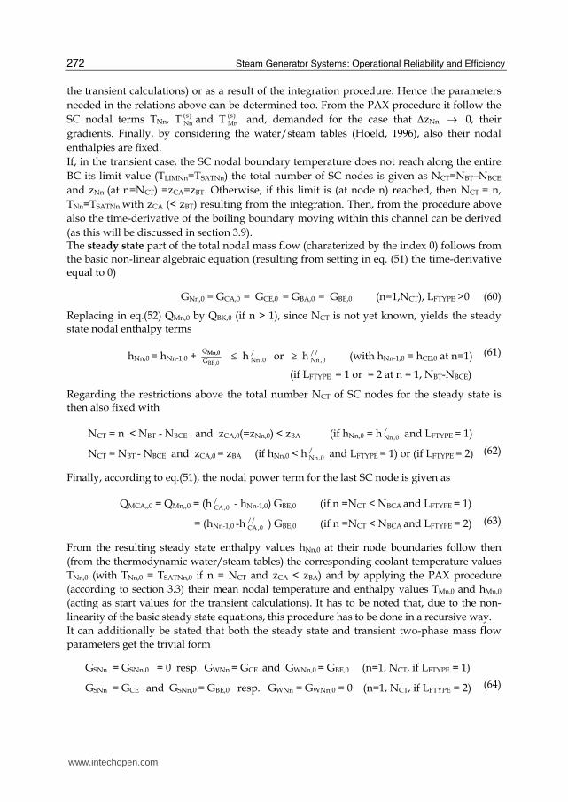
If, in the transient case, the SC nodal boundary temperature does not reach along the entire
BC its limit value (TLIMNn=TSATNn) the total number of SC nodes is given as NCT=NBT–NBCE
and zNn (at n=NCT) =zCA=zBT. Otherwise, if this limit is (at node n) reached, then NCT = n,
TNn=TSATNn with zCA (< zBT) resulting from the integration. Then, from the procedure above
also the time-derivative of the boiling boundary moving within this channel can be derived
(as this will be discussed in section 3.9). The steady state part of the total nodal mass flow (charaterized by the index 0) follows from
the basic non-linear algebraic equation (resulting from setting in eq. (51) the time-derivative
equal to 0)
GNn,0 = GCA,0 = GCE,0 = GBA,0 = GBE,0 (n=1,NCT), LFTYPE >0 (60)
Replacing in eq.(52) QMn,0 by QBK,0 (if n > 1), since NCT is not yet known, yields the steady state nodal enthalpy terms
hNn,0 = hNn-1,0 + BE,0
Q
G
Mn,0 ≤ h /Nn ,0 or ≥ h //
Nn ,0 (with hNn-1,0 = hCE,0 at n=1)
(if LFTYPE = 1 or = 2 at n = 1, NBT-NBCE)
(61)
Regarding the restrictions above the total number NCT of SC nodes for the steady state is then also fixed with
NCT = n < NBT - NBCE and zCA,0(=zNn,0) < zBA (if hNn,0 = h /Nn,0 and LFTYPE = 1)
NCT = NBT - NBCE and zCA,0 = zBA (if hNn,0 < h /Nn,0 and LFTYPE = 1) or (if LFTYPE = 2) (62)
Finally, according to eq.(51), the nodal power term for the last SC node is given as
QMCA,,0 = QMn,,0 = (h /CA ,0 - hNn-1,0) GBE,0 (if n =NCT < NBCA and LFTYPE = 1)
= (hNn-1,0 -h//CA,0 ) GBE,0 (if n =NCT < NBCA and LFTYPE = 2)
(63)
From the resulting steady state enthalpy values hNn,0 at their node boundaries follow then
(from the thermodynamic water/steam tables) the corresponding coolant temperature values
TNn,0 (with TNn,0 = TSATNn,0 if n = NCT and zCA < zBA) and by applying the PAX procedure
(according to section 3.3) their mean nodal temperature and enthalpy values TMn,0 and hMn,0
(acting as start values for the transient calculations). It has to be noted that, due to the non-
linearity of the basic steady state equations, this procedure has to be done in a recursive way.
It can additionally be stated that both the steady state and transient two-phase mass flow
parameters get the trivial form
GSNn = GSNn,0 = 0 resp. GWNn = GCE and GWNn,0 = GBE,0 (n=1, NCT, if LFTYPE = 1)
GSNn = GCE and GSNn,0 = GBE,0 resp. GWNn = GWNn,0 = 0 (n=1, NCT, if LFTYPE = 2) (64)
www.intechopen.com

Coolant Channel Module CCM. An Universally Applicable Thermal-Hydraulic Drift-Flux Based Separate-Region Mixture-Fluid Model
273
and
ddt
αMn = 0 and αNn = αNn,0 = αMn,0 = XNn = XNn,0 = 0 or = 1
(n=1, NCT, if LFTYPE =1 or = 2) (65)
3.8 Thermal-hydraulics of a SC with two-phase flow (LFTYPE = 0)
Similar as in the section before, the spatial integration of the two PDE-s of the conservation
eqs.(1) and (2) now over the (mixture-phase) SC nodes n (by taking into account the rules
from section 3.2, the relations from the eqs.(7) and (50) and the possibility of locally
changing nodal cross flow areas along the BC) yields for the transient case
- the total nodal mass flow terms
GNn = GNn-1 +VMn (ρ’- ρ’’)Mn ( ddt
αMn - α tGPn - α t
GZn ) = GNn-1 + G2An – G2Pn – G2Zn
(n=1,NCT, LFTYPE = 0) (66)
by introducing (if neglecting thereby the small differences between mean and nodal
saturation thermodynamic values) the coefficients
α tGPn = (
/ //
1
( )−ρ ρ )Mn[(1- α)ρ/P+ αρ//P]Mnddt
PSYS (67)
α tGZn = 1
2CE
Mn
A
Aα (s)
Mn ddt
zCE (n = 1 and zCE > zBE)
= 0 (1 < n < NCT)
a = CA
Mn
A
A (α (s)
CA - 12
α (s)Mn ) d
dtzCA (n = NCT, NCT>1 and zCA < zBA) (68)
and - the mean nodal void fraction time-derivatives
ddt
αMn = α tASn - α t
APn +α zCA
ddt
zNn +α zCE
ddt
zNn-1 = α tAn + α t
AZn (n=1,NCT and zCA=zBA) or (n=1, NCT-1, NCT>1 and zCA<zBA), LFTYPE=0
(69)
with the coefficients
α tASn = α t
AQn − α tAGn =
//Mn
1
ρ ( Mn
SWMn
q
h-
(s)SNn
Mn
G
A)
(70)
α tAPn =
//SW Mn
1( h )ρ [(1-α) ρ’h’P+ α(ρ’h’’P+ρ’’PhSW) - 1]Mn
ddt
PSYS (71)
www.intechopen.com

Steam Generator Systems: Operational Reliability and Efficiency
274
α tAZn = α t
GZn (72)
G (s)SNn = SNn
Nn
G
z
ΔΔ → G (z)
SNn = G ( )SNnα α (z)
Nn if αNn → αCE = 0 (at n=1)
or αNn → αCA = 1 (at n= NCT) (73)
It can again be expected that at the begin of each (intermediate) time step the mean nodal
void fraction values αMn
are known, either from steady state considerations (at the begin of
the transient calculations) or as a result of the integration procedure. Hence the parameters
needed in the relations above can be determined too. From the PAX procedure it follow
their nodal boundary void fraction terms αNn
together with their gradients α (z)Nn and α )z(
Mn .
The slopes α (s)Nn and α (s)
Mn can be established from their definition equations and thus, as
shown both in section 2.2.3 but also in the tables given by Hoeld (2001 and 2002a), all the
other characteristic two-phase parameters (such as steam, water or relative velocities etc). It
has again to be noted that, due to the non-linearity of the basic equation, this procedure has
to be done in a recursive way.
If, in the transient case, the SC nodal boundary void fraction αNn does not reach along the
entire BC its limit value (αLIMNn=1 or 0) the total number of SC nodes is given as NCT=NBT–
NBCE and zNn (at n=NCT) =zCA=zBT. Otherwise, if this limit is reached (at node n), then NCT =
n, αNn=1 (or =0) with zCA (< zBT) resulting from the integration. Then, from the procedure
above also the time-derivative of the boiling boundary moving within this channel can be
derived (as this will be discussed in section 3.9). Hence it follows for the steam mass flow gradients
G ( )SNnα = ACE vS0 ρ //
Nn with vS0 = vS (at αNn = 0) (n=1 and αNn → αCE = 0)
= ACAvW1 ρ /Nn with vW1 = vW (at αNn =1) (n=NCT-1 and αNn → αCA = 1 (74)
The term ddt
αMn can be eliminated in eq.(66) if inserting from eq.(69) yielding a relation
between GSNn and GNn
GNn + (/
//
ρρ -1)Mn GSNn = GXn (n=1,NCT, LFTYPE =0) (75)
with the ‘auxiliary’ mass flow term GXn referring only to values known from the node below
GXn = GNn-1+ (/
//
ρρ -1)Mn GSNn-1 + VMn ( ρ ’- ρ ’’)Mn ( α t
AQn - α tAPn - α t
GPn ) (76)
(n=1, NCT, LFTYPE =0)
A similar relation to GNn can be established from the drift flux correlation (eq.(18)). Thereby it has been taken advantage of the fact that the needed drift velocity vDNn and the phase distribution parameter C0Nn can be determined independently from the total mass flow GNn (and thus before this term is known). Hence, combining the eqs.(75) and (18) results in
www.intechopen.com
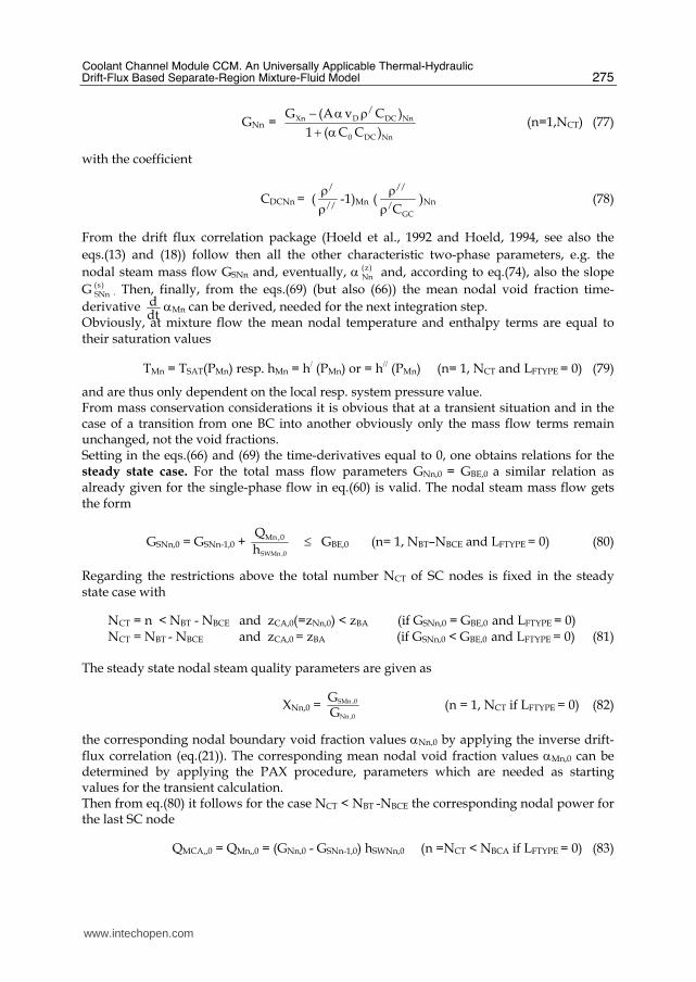
Coolant Channel Module CCM. An Universally Applicable Thermal-Hydraulic Drift-Flux Based Separate-Region Mixture-Fluid Model
275
GNn = /
Xn D DC Nn
0 DC Nn
G (A v C )
1 ( C C )
− α ρ+ α (n=1,NCT) (77)
with the coefficient
CDCNn = (/
//
ρρ -1)Mn (
//
/GCC
ρρ )Nn (78)
From the drift flux correlation package (Hoeld et al., 1992 and Hoeld, 1994, see also the
eqs.(13) and (18)) follow then all the other characteristic two-phase parameters, e.g. the
nodal steam mass flow GSNn and, eventually, α (z)Nn and, according to eq.(74), also the slope
G (s)SNn . Then, finally, from the eqs.(69) (but also (66)) the mean nodal void fraction time-
derivative ddt
αMn can be derived, needed for the next integration step. Obviously, at mixture flow the mean nodal temperature and enthalpy terms are equal to their saturation values
TMn = TSAT(PMn) resp. hMn = h/ (PMn) or = h// (PMn) (n= 1, NCT and LFTYPE = 0) (79)
and are thus only dependent on the local resp. system pressure value. From mass conservation considerations it is obvious that at a transient situation and in the case of a transition from one BC into another obviously only the mass flow terms remain unchanged, not the void fractions. Setting in the eqs.(66) and (69) the time-derivatives equal to 0, one obtains relations for the steady state case. For the total mass flow parameters GNn,0 = GBE,0 a similar relation as already given for the single-phase flow in eq.(60) is valid. The nodal steam mass flow gets the form
GSNn,0 = GSNn-1,0 + SWMn ,0
Mn ,0Q
h ≤ GBE,0 (n= 1, NBT–NBCE and LFTYPE = 0) (80)
Regarding the restrictions above the total number NCT of SC nodes is fixed in the steady state case with
NCT = n < NBT - NBCE and zCA,0(=zNn,0) < zBA (if GSNn,0 = GBE,0 and LFTYPE = 0) NCT = NBT - NBCE and zCA,0 = zBA (if GSNn,0 < GBE,0 and LFTYPE = 0) (81)
The steady state nodal steam quality parameters are given as
XNn,0 = SMn ,0
Nn ,0
GG
(n = 1, NCT if LFTYPE = 0) (82)
the corresponding nodal boundary void fraction values αNn,0 by applying the inverse drift-flux correlation (eq.(21)). The corresponding mean nodal void fraction values αMn,0 can be determined by applying the PAX procedure, parameters which are needed as starting values for the transient calculation. Then from eq.(80) it follows for the case NCT < NBT -NBCE the corresponding nodal power for the last SC node
QMCA,,0 = QMn,,0 = (GNn,0 - GSNn-1,0) hSWNn,0 (n =NCT < NBCA if LFTYPE = 0) (83)
www.intechopen.com

Steam Generator Systems: Operational Reliability and Efficiency
276
3.9 SC boundaries
The SC entrance position zCE (= zNn at n=0) is either equal to the BC entrance zBE (for the first SC within the BC) or equal to the SC outlet boundary of the SC before. In the steady state case the SC outlet boundary (= boiling boundary zBB,0 or mixture level zML,0) can be represented as
zCA,0 = zBA (n = NCT and zCA,0 = zBA)
= zNn-1 + ΔzCA,0 (n = NCT and zCA,0 < zBA) (84)
The (steady state) term NCT is already determined in the eqs.(62) or (81), the corresponding nodal power QMCA,0 given by the eqs.(63) or (80). Hence after rearranging eq.(32) one gets an
algebraic quadratic equation with respect to ΔzCA,0
QMCA,0 = QMn,,0 = ΔzCA,0 [qLBk-1 + 12
LBk ,0 LBk 1,0
Bk
q qz
−−Δ ΔzCA,0]
(n = NCT and k= NBCA if NCT< NBCA) (85)
yielding finally as solution
ΔzCA,0 = ΔzBk (n = NCT and k= NBCA if NCT = NBT)
= ΔzBk LBk 1,0
LBk 1,0 LBk ,0
qq q
−− − [1 - LBK,0 CMA,0
LBk-1,0 Bk LBMk-1,0
q Q1 - 2(1 - ) q z qΔ ]
(k= NBCA if NCT < NBT)
→ MCA ,0
LBk 1,0
Qq − [1 + 1
2(1 - LBk ,0
LBk 1,0
q q − ) CMA ,0
Bk LBk 1,0q
Qz −Δ ] if qLBk,0 → qLBk-1,0 (86)
From the relations in section 3.5 then also the other steady state power terms can be determined. In the transient case the outlet boundary zCA (=boiling boundary or mixture level) follows,
as already pointed-out, directly from the integration procedure. Then also ΔzCA and NCT are fixed. This SC outlet boundary zCA can move along the entire BC and thus also cross BC node boundaries. A SC can even shrink to a single node (NCT =1), start to disappear or to be created anew. This means that in PAX the slope in the vicinity of such a boundary is replaced by a gradient. The mean nodal coolant temperature or, if LFTYPE=0, void fraction of the last SC node is interrelated by the PAX procedure with the locally varying SC outlet boundary zCA Hence, in a transient situation the time-derivative of only one of these parameters is demanded, after the integration then the second one follows from the PAX procedure. If combining (in the case of single-phase flow) the eqs.(42) and (52), the wanted relation for the SC boundary time derivative can be expressed by
ddt
zCA = ddt
zBB = t tPXCA TCAz zTCA PXCA
T T
T T
−− or = 0 (n = NCT, zCA < zBA or zCA = zBA if LFTYPE > 0) (87)
and, if considering the eqs. (42) and (69), for the case of mixture flow
ddt
zCA= ddt
zML= t tPXCA ACAz zACA PXCA
α − αα − α or = 0 (n = NCT, zCA < zBA or zCA = zBA if LFTYPE = 0) (88)
www.intechopen.com

Coolant Channel Module CCM. An Universally Applicable Thermal-Hydraulic Drift-Flux Based Separate-Region Mixture-Fluid Model
277
If zCA < zBA, the corresponding time-derivatives ddt
TMn or ddt
αMn of the last SC node (at
n=NCT) follow then by inserting the terms above into the eqs.(52) or (69). After the
integration procedure then the SC outlet boundary zCA (= boiling boundary zBB or mixture
level zML) and thus also the total number NCT of SC nodes is given.
In these considerations it is excluded that a BC node can contain more than one moving
boundary. Hence a SC with NCT=1 can only appear at BC entrance (zCE = zBE) or BC outlet
(zCA = zBA). For such a special case either the temperature slope (T zCEI ) resp. (at mixture fluid
conditions) the term α zCEI at SC entrance are needed as input to the PAX procedure (see
section 3.3.1).
3.10 Pressure profile along the SC (and thus also BC)
After having solved the mass and energy balance equations separately (and not
simultaneously) with the momentum balance the now exact nodal SC and BC pressure
difference terms (ΔPNn = PNn - PNn-1 and ΔPBNn) can (for both single- or two-phase flow
situations) be determined by discretizing the momentum balance eq.(3) and integrating over
the corresponding SC nodes. The total BC pressure difference ΔPBT = PBA - PBE between BC
outlet and entrance follows then from the relation
ΔPBT = ΔPPBT - ΔPGBT
(with ΔPGBT,0 = 0 at steady state conditions)(89)
with
ΔPPBT = ΔPSBT + ΔPABT + ΔPXBT + ΔPFBT + ΔPDBT
(with ΔPPBT,0 = ΔPBTIN,0 at steady state conditions) (90)
comprising terms from static head (ΔPSBT), mass acceleration (ΔPABT), wall friction (ΔPFBT)
and external pressure accelerations (ΔPXBT, pump or other perturbations from outside) and
(in the transient case) the pressure difference term ΔPGBT which takes care of the time-
dependent changes in total mass flux along a BC (caused by the direct influence of changing
nodal mass fluxes) having the form
ΔPGBT = ∫BTz
0dtd
GFB(z,t) dz = zBT dtd GFBMT at transient conditions
= 0 at steady state (91)
Thereby the ‘fictive’ mean mass flux term GFBMT (averaged over the entire BC) has been
introduced which can be represented as
GFBMT = BTz1 ∫BTz
0GFB(z,t) dz
≅
BTz1 ∑SCTN ∑= ΔCTN
1nNnz GFBMn =
21
BTz1
∑=BTN
1k BMk
BkA
zΔ (GBk + GBK-1) (92)
www.intechopen.com
Steam Generator Systems: Operational Reliability and Efficiency
278
Its time derivative can be estimated as
dtd GFBMT ≅
tGG FBMTBFBMTΔ
−
→ (dtd GFBMT)at t=tB if Δt=t-tB → 0 (Index B = begin of time-step)
(93)
Regarding, however, the friction correlations, there arises the problem how to consider correctly contributions from spacers, tube bends, abrupt changes in cross sections etc. as
well. The entire friction pressure decrease (ΔPFBT) along a BC can thus never be described solely by analytical expressions in a satisfactory manner. To minimize these uncertainties a further friction term will be included into these considerations having the form
ΔPDBT = (fFMP,0 - 1) ΔPFBT + ΔPFADD (94)
This means that eq.(90) is either supplemented with an additive term (index FADD) or the friction parts are provided with a multiplicative factor fFMP,0. Which of them should prevail
can be governed from outside by an input coefficient εDPZ = εDPZI. Thereby, the additive part will be assumed to be proportional to the square of the total coolant mass flow (e.g., at BC entrance)
ΔPFADD = - fADD,0 zBT (F F
HW
G |G |
2 dρ )BE (95)
At steady state conditions the total BC pressure difference term (ΔPBT,0) is known from input
(ΔPBT,0 = ΔPBTIN). Since ΔPGBT,0 = 0, the steady state total additional term ΔPDBT,0 results from
eq.(90). If defining the additive steady state friction pressure difference ΔPFADD,0 to be the (1-
εDPZ)-th part of the total additional pressure difference term then
ΔPFADD,0 = (1 - εDPZ) ΔPDBT,0 (96)
The corresponding additive friction factor fADD,0 follows then directly from eq.(95), the multiplicative one fFMP,0 from the combination of the eqs.(94) and (96)
fFMP,0 = 1+ εDPZ DBT ,0
FBT ,0
PP
ΔΔ (97)
There arises the question how the validity of both friction factors can be expanded to transient situations too. This can, for example, be done by assuming that they should remain time-independent. Then, finally, the wanted nodal pressure decrease terms can be determined for both steady state but also transient situations. By adding now the resulting nodal BC pressure difference terms to the (time-varying) system pressure PSYS(t) (given from outside as boundary condition with respect to a certain position (in- or outside of the BC) then finally also the absolute nodal pressure profile PBk along the BC can be established (needed at the begin of the next time step for the determination of the constitutive equations).
3.11 BC entrance mass flow (‘Open and closed channel concept’)
As to be seen from the sections above in order to be able to calculate the characteristic nodal and total single- and two-phase parameters along a BC the BC entrance mass flow must be
www.intechopen.com

Coolant Channel Module CCM. An Universally Applicable Thermal-Hydraulic Drift-Flux Based Separate-Region Mixture-Fluid Model
279
known. This term is for the steady state case given by input (GBE = GBEIN), together with the two pressure entrance and outlet values (PBE = PBEIN, PBA = PBAIN). In the transient situation it can, however, be expected that for the normal case of an ‘open’ channel besides the entrance mass flow only one of these two pressure terms is known from input, either at BC entrance or outlet. The missing one follows then from the calculation of the pressure decrease parts. Such a procedure can not be applied without problems if the channels are part of a complex set of closed loops, loops consisting of more than one coolant channel (and not driven by an outside source, such as a pump). Then the mass flow terms (and especially entrance term of at least one of the channel) has to be adjusted to the fact that the sum of the entire pressure decrease terms along such a closed circuit must be zero. Usually, in the common thermal-hydraulic codes (see for example the ‘separate-phase’ approaches) this problem is handled by solving the three (or more) fundamental equations for the entire complex system simultaneously, a procedure which affords very often immense computational times and costs. In the here applied module (based on a separate treatment of momentum from mass and energy balance) a more elegant method could be found by introducing an additional aspect into the theory of CCM. It allows, different to other approaches, taking care of this situation by solving this problem by means of a ‘closed channel concept’ (in contrast to the usual ‘open channel’ method). Choosing for this purpose a characteristic ‘closed’ channel within such a complex loop it can
be expected that its pressure difference term ΔPBT = ΔPBA - ΔPBE over this channel is fix (= negative sum of all the other decrease terms of the remaining channels which can be calculated by the usual methods). Thus also the outlet and entrance BC pressure values
(PBAIN, ΔPBEIN) are now also available as inputs to CCM. Since, according to eq.(91), then also
the term ΔPPBT is known, it follows from eq.(95) the ‘closed channel concept criterion’
zBT ddt
GFBMT = ΔPGBT = ΔPPBT − ΔPBTIN (at ‘closed channel’ conditions) (98)
This means that for this purpose the total mass flow along a BC (and thus also at its entrance) must be adapted in such a way that the above for the ‘closed channel’ concept essential criterion remains valid at each time step, i.e., that the actual time derivative of the mean mass flux GFBMT averaged over the channel must, as recommended by eq.(92), agree in a satisfactory manner with the required one from the equation above.
There exist, obviously, different methods how to deal with this complicated problem. One of
them could be to determine the entrance mass flow GBE by changing this value in a recursive
way until the resulting termdtd GFBMT agrees with the criterion above.
Another possibility is to find a relation between the time-derivatives of the mean and certain
local mass flux values (e.g., at BC entrance), i.e., to establish for example a relation between
the terms dtd GFBMT and
dtd GFBE. Then the wanted mass flow time-derivative at BC entrance
can be determined directly from eq.(98). One practicable method to establish such a relation
could follow if considering that a change of the mass flux is propagating along the channel
so fast that the time derivative of its mean values could be set (in a first step) almost equal to
the time-derivative at its entrance value. This term can, eventually, be provided with a form
factor which can be adapted by an adequate recursion procedure until the condition of
eq.(98) is fulfilled. The so won entrance mass flow is then governing the mass flow
behaviour of the entire loop.
www.intechopen.com

Steam Generator Systems: Operational Reliability and Efficiency
280
This method has been applied within the UTSG-3 code (Hoeld, 2011) for the simulation of
the natural-circulation behaviour of the secondary steam generator loop. Similar
considerations have been undertaken for a 3D case where the automatic mass flow
distribution into different entrances of a set of parallel channels is asked (See e.g. Hoeld,
2004a and Jewer et al., 2005). The experience of such calculations should help to decide
which of the different possible procedures should finally be given preference.
The ‘open/closed channel concept’ makes sure that measures with regard to the entire
closed loop do not need to be taken into account simultaneously but (for each channel)
separately. Its application can be restricted to only one ‘characteristic’ channel of a sequence
of channels within a complex loop. This additional tool of CCM can in such cases help to
handle the variety of closed loops within a complex physical system in a very comfortable
way.
4. Code package CCM
Starting from the above presented ‘drift-flux based mixture-fluid theory’ the (1D) thermal-
hydraulic coolant channel module CCM could be established. It was derived with the
intention to provide the authors of different and sometimes very complex thermal-hydraulic
codes with a general and easily applicable tool needed for the simulation of the steady state
and transient behaviours of the most important single- and two-phase parameters along any
type of heated or cooled coolant channel.
The subdivision of such a (basic) channel (BC), characterized by an own key number
(KEYBC), into different sub-channels (SC-s), characterized by its fluid type (LFTYPE), is done
automatically within the module. Thereby the different SC-s will change from one SC type
to another, i.e. two-phase flow follows single-phase flow and vice versa. SC-s can shrink to a
single node or even disappear but also be created anew. The SC inlet boundary conditions
are either identical to the entrance conditions of the BC or to the outlet parameters of the SC
before.
The module CCM has been constructed in such a way that only input data with regard to
the BC are demanded. These input data (for each channel KEYBC) will be transferred to the
CCM by only two types of commons containing data established in the calling overall
program, allowing thus a very easy handling of the code:
• The first common is only occupied by fixed BC geometry data (such as channel length, elevation heights, fixed or varying cross sections, hydraulic diameters).
• The second one has to contain resulting data coming from the (overall) integration procedure (such as mean nodal coolant temperature or mean nodal steam void fraction values, boiling boundary and mixture level along the BC) and (in the case of a closed loop) the total mass flow term at BC entrance
and moreover parameters representing the initial and boundary conditions of the system such as the nodal power profile (entrance power density qBCE and mean nodal mean power values QBMk),the coolant temperature, mass flow and pressure terms at BC entrance (TBE, GBE, PBE) and, in the case of steady state conditions or at transient situations with a BC being a part of an ‘open channel’, also the pressure term (PBE or PBA) at BC entrance or outlet.
www.intechopen.com
Coolant Channel Module CCM. An Universally Applicable Thermal-Hydraulic Drift-Flux Based Separate-Region Mixture-Fluid Model
281
At the end of a recursion- or time-step characteristic parameters of all SC-s are transferred to
the corresponding BC positions, thus yielding, for example, a final set of (non-linear)
algebraic or (in the transient case) non-linear ordinary differential equations (ODE-s) of 1-st
order together with the parameters following from the constitutive equations of CCM. The
resulting sets of equations for different channels appearing in a complex physical system
can be combined with other sets of algebraic equations or ODE-s coming from additional
parts of such a complex model (considerations with respect to heat transfer, nuclear kinetics,
top plenum, downcomer etc.). The final overall sets can then be solved by applying
adequate algebraic solution methods or an appropriate time-integration routine (See, for
example, Hoeld, 2011).
As output CCM will then yield all the wanted and needed characteristic thermal-hydraulic
single- and two-phase BC (and thus also SC) parameters of such a general coolant channel.
These are:
• Time-derivatives of the mean nodal coolant fluid temperatures
• time-derivatives of the mean nodal void fractions
• time-derivatives describing the movements of the boiling boundary or mixture level within the BC
• time-derivative of the total mass flow entering the BC (at least for the case that the BC is a part of a closed loop and thus being, for example, of interest for a thermal-hydraulic 3D representation),
• other constitutive nodal BC boundary parameters such as terms for total, water and steam mass flow, for pressure and pressure drop, coolant temperatures, void fraction etc.
The module CCM has been continuously expanded into a very efficient and mature version.
To analyze transient situations at normal operational conditions sometimes also very simple
codes (‘pen’ codes) can be applied. The quality of a code has, however, to be proved in the
context of how reliably complex or limit cases can be handled. Thus much weight and effort
has been placed on the question of how the performance of CCM, especially at extreme
situations, can be judged, i.e., in cases where the mass flow ceases to stagnant conditions,
the power input decreases to zero, abrupt pressure changes (for example due to a fast
opening or closing of valves), the boiling boundary or mixture level disappear, the coolant
channel starts to dry-out etc.
The special case of water or steam mass flow terms being exchanged at node boundaries
between two parallel ‘porous’ coolant channels (with pressure differences as driving forces)
has not yet been taken into account.
5. Verification and validation (V & V) procedures
During the course of development of the different versions of the code combination UTSG-
3/CCM has gone through an appropriate verification and validation (V&V) procedure (with
continuous feedbacks being considered in the continual formulation of the theoretical
model).
CCM is (similar as done in the separate-phase models) constructed with the objective to be used only as an element within an overall code. Hence, further V&V steps could be performed only in an indirect way, i.e. in combination with such overall codes. This has been done in a very successful way by means of the U-tube steam generator code UTSG-3. Thereby the module CCM could profit from the experiences been gained in decades of years
www.intechopen.com

Steam Generator Systems: Operational Reliability and Efficiency
282
work with the construction of an effective non-linear one-dimensional theoretical model and, based on it, corresponding digital code UTSG-2 for vertical, natural-circulation U-tube steam generators (Hoeld, 1978 and 1990) and now also the new advanced code version UTSG-3 (Hoeld 2002b, 2004). The good agreement of the test calculations with similar calculations of earlier versions applied to the same transient cases demonstrates that despite of the continuous improvements of the code UTSG and the incorporation of CCM into UTSG-3 the newest and advanced version has still preserved its validity. A more detailed description over these general V&V measures demonstrated on one characteristic test case can be found in (Hoeld, 2011).
6. Conclusions
The universally applicable coolant channel module CCM allows describing the thermal-hydraulic situation of fluids flowing along up-, horizontal or downwards channels with fluids changing between sub-cooled, saturated and superheated conditions. It must be recognized that CCM represents a complete system in its own right, which requires only BC-related, and thus easily available, input values (geometry data, initial and boundary conditions, resulting parameters from integration). The partitioning into SC-s is done automatically within the module, without requiring any special actions on the part of the user. At the end of a time-step the characteristic parameters of all SC-s are transferred to the corresponding BC positions, thus yielding the final set of ODE-s together with the parameters following from the constitutive equations of CCM. In contrast to the currently very dominant separate-phase models, the existing theoretical inconsistencies in describing a two-phase fluid flowing along a coolant channel if changing between single-phase and two-phase conditions and vice versa can be circumvented in a very elegant way in the ‘separate-region’ mixture-fluid model presented here. A very unique technique has been established built on the concept of subdividing a basic channel (BC) into different subchannels (SC-s), thus yielding exact solutions of the basic drift-flux supported conservation equations. This type of approach shows, as discussed in (Hoeld, 2004b), distinct advantages vs. ‘separate phase’ codes, especially if taking into account
• the quality of the fundamental equations (basic conservation equations following directly from physical laws supported by experimentally based constitutive equations vs. split ‘field’ equations with artificial closure terms),
• the special solution methods due to the detailed interpolation procedure from PAX allowing to calculate the exact movement of boiling boundaries and mixture (or dry-out) levels (different to the ‘donor-cell averaging’ methods yielding mostly only ‘condensed’ levels),
• the possibility to take advantage of the ‘closed-channel concept’ (needed for example for thermal- hydraulic 3D considerations) allowing thus to decouple a characteristic (‘closed’) channel from other parts of a complex system of loops,
• the speed of the computation,
• the derivation of the theory in close connection with the establishment of the code by taking advantage of feedbacks coming from both sides,
• the considerable effort that has been made in verifying and checking the CCM (besides an extensive V & V procedure), with respect to the applicability and adjustment and also for very extreme situations,
www.intechopen.com

Coolant Channel Module CCM. An Universally Applicable Thermal-Hydraulic Drift-Flux Based Separate-Region Mixture-Fluid Model
283
• its easy applicability,
• the maturity of the module, which is continuously enhanced by new application cases.
• taking advantage of the fact that most of the development work for the coolant channel thermal-hydraulics has already been shifted to this module (including the special provisions for extreme situations such as stagnant flow, zero power or zero sub-cooling, test calculations for the verification and validation of the code etc.).
The existence of the resulting widely verified and validated module CCM represents an important basic element for the construction of a variety of other comprehensive thermal-hydraulic models and codes as well. Such models and modules can be needed for the simulation of the steady state and transient behaviour of different types of steam generators with special primary and secondary loops (vertical U-tube, vertical once-through or horizontal VVER-440 or -1000 assembles). One main field of application will be (and is already) the simulation of a 3D thermal-hydraulic situation by a number of parallel channels (reactor cores, VVER steam generators etc.), the (basic) channels distinguished by different key numbers NTYPES. It shows special advantages in view of the determination of the mass flow distribution into different coolant channels after non-symmetric perturbations see (Hoeld, 2004a) or (Jewer et al., 2005), a problem which is far from being solved in many of the newest 3D studies. It allows also studying the validity of the ‘open channel’ method in a very detailed form. The introduction of varying cross sections along the z axis allows to take care also of thermal
non-equilibrium situations by simulating the two separate phases by two with each other
interacting basic channels (for example if sub-cooled water rays are injected into a steam
dome).
The resulting equations for different channels appearing in a complex physical system can
be combined with other sets of algebraic equations and ODE-s coming from additional parts
of such a complex model (heat transfer or nuclear kinetics considerations, top plenum, main
steam system and downcomer of a steam generator etc.). The final overall set of ODE-s can
then be solved by applying an appropriate time-integration routine. See for example (Hoeld,
2011).
The enormous efforts already made in the verification and validation of the codes UTSG-3, its application in a number of transient calculations at very extreme transient situations (fast opening of safety valves, dry out of the total channel with SC-s disappearing or created anew) brings the code and thus also CCM to a very mature and (what is important) easily applicable state. However, there is not yet enough experience to judge how the potential of the mixture-fluid models and especially of CCM can be expanded to other extreme cases (e.g., water and steam hammer). Is it justified to prefer separate-phase models versus the drift-flux based (and thus non-homogeneous) mixture fluid models? This depends, among other criteria, also on the quality of the special models and their exact derivation. Considering the arguments presented above it can, however, be stated that in general the here presented module can be judged as a very satisfactory approach.
7. Nomenclature
ABk m² BC cross sectional area (at BC node boundary k)
www.intechopen.com
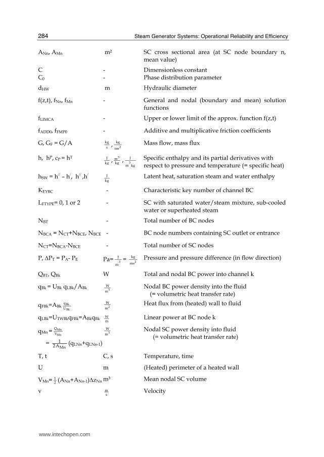
Steam Generator Systems: Operational Reliability and Efficiency
284
ANn, AMn m² SC cross sectional area (at SC node boundary n, mean value)
C C0
- -
Dimensionless constant Phase distribution parameter
dHW m Hydraulic diameter
f(z,t), fNn, fMn - General and nodal (boundary and mean) solution functions
fLIMCA - Upper or lower limit of the approx. function f(z,t)
fADD0, fFMP0 - Additive and multiplicative friction coefficients
G, GF = G/A kg
s,
2
kg
sm Mass flow, mass flux
h, hP, cP = hT
J
kg,
3mkg
,3
J
m kg Specific enthalpy and its partial derivatives with
respect to pressure and temperature (= specific heat)
hSW = h// – h/, h// ,h/ J
kg Latent heat, saturation steam and water enthalpy
KEYBC - Characteristic key number of channel BC
LFTYPE= 0, 1 or 2 - SC with saturated water/steam mixture, sub-cooled water or superheated steam
NBT - Total number of BC nodes
NBCA = NCT+NBCE, NBCE - BC node numbers containing SC outlet or entrance
NCT=NBCA-NBCE - Total number of SC nodes
P, ΔPT = PA- PE Pa=3
J
m=
2
kg
ms Pressure and pressure difference (in flow direction)
QBT, QBk W Total and nodal BC power into channel k
qBk = UBk qLBk/ABk 3
W
m Nodal BC power density into the fluid
(= volumetric heat transfer rate)
qFBk=ABkBk
Bk
q
U 2
W
m Heat flux from (heated) wall to fluid
qLBk=UTWBkqFBk=ABkqBk Wm
Linear power at BC node k
qMn = Mn
Mn
Q
V
= MnA21 (qLNn+qLNn-1)
3
W
m Nodal SC power density into fluid
(= volumetric heat transfer rate)
T, t C, s Temperature, time
U m (Heated) perimeter of a heated wall
VMn= 12
(ANn+ANn-1)ΔzNn m³ Mean nodal SC volume
v ms
Velocity
www.intechopen.com

Coolant Channel Module CCM. An Universally Applicable Thermal-Hydraulic Drift-Flux Based Separate-Region Mixture-Fluid Model
285
X= SG
G or =
/
SW
h hh− - Steam quality (2-phase and expanded to 1-phase
flow)
z, ΔzNn=zNn-zNn-1 m Local position, SC node length (zNn-1=zCE at n=0)
zBA-zBE=zBT,zCA-zCE=zCT m BC and SC outlet and entrance positions, total length
zBB, zML m Boiling boundary and mixture level within a BC
α - Void fraction
αTWk 2
W
m C Heat transfer coefficient along a BC wall surface
Δ - Nodal differences
εDPZ - Coefficient controlling the additional friction part
εQTW - Correction factor with respect to QNOM,0
εTW m Abs. roughness of tube wall (εTW/dHW = relative value)
Φ 22PF - Two-phase multiplier
ΦZG - Angle between upwards and flow direction
ρ, ρ P, ρ T 3
kg
m,
kg
J,
3
kg
m C Density and their partial derivatives with respect to
(system) pressure and temperature
Θ s Time constant
∂ - Partial derivative
Subscripts
0, 0 (=E or BE) Steady state or entrance to SC or BC (n or k =0)
A, E, T (=AE) Outlet, entrance, total (i.e. from outlet to entrance)
B, S Basic channel or sub-channel (=channel region)
A, S, F, D, X (P=A+S+F+D+X) and G
Acceleration, static head, direct and additional friction and external pressure differences
(in connection with ΔP) and pressure differences due to changes in mass flux
Mn, BMk Mean values over SC or BC nodes
Nn, Bk SC or BC node boundaries (n = 0 or k = 0: SC or BC entrances)
D Drift
S, W Steam, water
P, T Derivative at constant pressure or temperature
TW Tube wall surface
www.intechopen.com

Steam Generator Systems: Operational Reliability and Efficiency
286
Superscripts
/, // Saturated water or steam
P, T Partial derivatives with respect to P or T
(GS), ( α ), z, s Partial derivatives with respect to GS, α or z (=gradient), slope
8. References
Austregesilo H. et al. 2003. ATHLET Mod 2.0, Cycle A, Models and methods. GRS-P-1/Vol.4. Bencik,V.& Hoeld, A.1991. Experiences in the validation of large advanced modular system codes.
1991 SCS Simulation MultiConf., April 1-5, New Orleans Bencik,V.& Hoeld, A.1993. Steam collector and main steam system in a multi-loop PWR NPP
representation. Simulation MultiConf., March 29-April 1, Arlington/Washington Bestion, D. 1990. The physical closure laws in CATHARE code. Nucl.Eng.& Design 124, 229- 245 Burwell, J. et al. 1989. The thermohydraulic code ATHLET for analysis of PWR and SWR system,
Proc.of 4-th Int. Topical Meeting on Nuclear Reactor Thermal-Hydraulics, NURETH–4, Oct.10-13, Karlsruhe
Dunn, F.E. 1998. Thermal-hydraulic calculations in the SAS-DIF3DK coupled reactor physics and thermal-hydraulics code. Int.ernational Topical Meeting on Safety of Operating Reactors, Oct.11-14, San Francisco
Fabic, S. 1996. How good are thermal-hydraulics codes for analyses of plant transients. International ENS/HND Conference, 7-9 Oct. 1996, Proc.193-201, Opatija/Croatia
Haar, L., Gallagher, J.S., Kell, G.S. 1988. NBS/NRC Wasserdampftafeln. London/Paris/New York 1988
Hanna, B.N., 1998. CATENA. A thermalhydraulic code for CANDU analysis. Nucl. Eng. Des. 180 (1998) 113-131.
Hoeld, A. 1978. A theoretical model for the calculation of large transients in nuclear natural circulation U-tube steam generators (Digital code UTSG). Nucl. Eng. Des.(1978), 47, 1.
Hoeld, A. 1988a. HETRAC: A heat transfer coefficients package. GRS-A-1446, May. Hoeld, A. 1988b. Calculation of the time behavior of PWR NPP during a loss of a feedwater ATWS
case. NUCSAFE 88, 2-7 October, Proc. 1037-1047, Avignon, France. Hoeld, A.1990a. UTSG-2. A theoretical model describing the transient behaviour of a PWR natural-
circulation U-tube steam generator. Nuclear Techn. 90, 98-118, April. Hoeld, A. 1990b. The code ATHLET as a vValuable tool for the analysis of transients with and
without SCRAM, SCS Eastern MultiConf,23-26 April, Nashville, Tennessee. Hoeld, A., Jakubowska, E., Miro, J.E & Sonnenburg,H.G. 1992. A comparative study on slip and
drift- flux correlations. GRS-A-1879, Jan. 1992 Hoeld, A. 1994. Drift-Flux Paket MDS auf der Basis der SONNENBURG-Korrelation. GRS,
Technische Notiz , TN-HOD-01/94, Juni 1994. Hoeld, A. 1996. Thermodynamisches Stoffwertpaket MPP für Wasser und Dampf. GRS,
Technische Notiz, TN-HOD-1/96, Mai. Hoeld, A. 1999. An Advanced Natural-Circulation U-tube Steam Generator Model and Code
UTSG-3, EUROTHERM-SEMINAR No.63, September 6-8, Genoa, Italy. Hoeld, A. 2000. The module CCM for the simulation of the thermal-hydraulic situation within a
coolant channel. Intern. NSS/ENS Conference, September 11-14, Bled, Slovenia.
www.intechopen.com

Coolant Channel Module CCM. An Universally Applicable Thermal-Hydraulic Drift-Flux Based Separate-Region Mixture-Fluid Model
287
Hoeld, A. 2001. The drift-flux correlation package MDS. 9-th International Conference on Nuclear Engineering (ICONE-9), 8-12 April, Nice, France.
Hoeld, A. 2002a. The consideration of entrainment in the drift-flux correlation package MDS. 10-th Int. Conference on Nuclear Engineering (ICONE-10), April 14-18, Arlington, USA.
Hoeld, A. 2002b. A steam generator code on the basis of the general coolant channel module CCM. PHYSOR 2002, October 7-10, Seoul, Korea.
Hoeld,A. 2004a. A theoretical concept for a thermal-hydraulic 3D parallel channel core model. PHYSOR 2004, April 25-29, Chicago, USA.
Hoeld, A. 2004b. Are separate-phase thermal-hydraulic models better than mixture-fluid approaches. It depends. Rather not. Int. Conference on Nuclear Engineering for New Europe 2004’. Sept. 6-9, Portoroz, Slovenia.
Hoeld, A. 2005. A thermal-hydraulic drift-flux based mixture-fluid model for the description of single- and two-phase flow along a general coolant channel. The 11-th International Topical Meeting on Nuclear Reactor Thermal-Hydraulics (NURETH-11). Paper 144. Oct. 2-6, 2005, Avignon, France.
Hoeld, A. 2007a. Coolant channel module CCM. An universally applicable thermal-hydraulic drift-flux based mixture-fluid 1D model and code. Nucl. Eng. and Design 237(2007), 1952-1967
Hoeld, A. 2007b. Application of the mixture-fluid channel element CCM within the U-tube steam generator code UTSG-3 for transient thermal-hydraulic calculations.15-th International Conference on Nuclear Engineering (ICONE-15). Paper 10206. April 22-26, 2007, Nagoya, Japan
Hoeld, A. 2011. The thermal-hydraulic U-tube steam generator model and code UTSG3 (Based on the universally applicable coolant channel module CCM). Intech Open Access Book ‘Steam Generator Systems’, ISBN 978-953-7619-X-X, InTech, Austria, Available from: http://sciyo.com/articles/show/title/ The thermal-hydraulic U-tube steam generator model and code UTSG3 (Based on the universally applicable coolant channel module CCM).
Ishii, M. 1990. Two-Fluid Model for Two-Phase Flow, Multiphase Sci. and Techn. 5.1, Hemisphere Publ. Corp.
Ishii, M. and Mishima, K. 1980. Study of two-fluid model and interfacial area. NUREG/CR-1873 (ANL-80-111), Dec.
Jewer, S., Beeley, P., Thompson, A. & Hoeld, A. 2005. Initial version of an integrated thermal-hydraulic and neutron kinetics 3D code X3D. ICONE13, May 16-20, Beijing. See also NED 236(2006),1533-1546.
Lerchl G. et al. 2009. ATHLET Mod 2.2, Cycle B, User’s Manual’. GRS-P-1/Vol.1. Rev. 5, July Liles D. R. et al. 1988. TRAC-PF1/MOD1 – Correlations and Models. NUREG/CR-5069, LA-
11208-MS, Dec. Martinelli, R.C., Nelson, D.B. 1948. Prediction of pressure drop during forced-circulation of boiling
water. Trans. ASME 70, 695. Moody, N.L.F. 1994. Friction factors for pipe flow. Trans. ASME, 66, 671 (See also VDI–
Wärmeatlas, 7.Auflage, 1994, VDI - Verlag). Schmidt, E.& Grigull, U.(ed.) 1982. Properties of water and steam in SI-Units. Springer-Verlag. Sonnenburg, H.G. 1989. Full-range drift-flux model based on the combination of drift-flux theory
with envelope theory, NURETH-4, pp.1003-1009, Oct.10-13, Karlsruhe.
www.intechopen.com

Steam Generator Systems: Operational Reliability and Efficiency
288
Shultz, R.R. 2003. RELAP5-3D code manual. Volume V: User’s guidelines. INEEL-EXT-98-00084. Rev.2.2, October.
US-NRC. 2001a.TRAC-M/FORTRAN90 (Version 3.0). Theory Manual, NUREG/CR-6724, April
US-NRC. 2001b. RELAP5/ MOD3.3. Code Manual. Volume I, NUREG/CR-5535, December Wulff, W. 1987. Computational methods for multiphase flow, 2-nd Int. Workshop on Two-phase
Flow Fundamentals, Rensselaer Pol. Inst., March 15-20. Zuber, N.& Findlay, J.A., 1965. Average volume concentration in two-phase flow systems, J. Heat
Transfer 87, 453
www.intechopen.com

Steam Generator Systems: Operational Reliability and EfficiencyEdited by Dr. Valentin Uchanin
ISBN 978-953-307-303-3Hard cover, 424 pagesPublisher InTechPublished online 16, March, 2011Published in print edition March, 2011
InTech EuropeUniversity Campus STeP Ri Slavka Krautzeka 83/A 51000 Rijeka, Croatia Phone: +385 (51) 770 447 Fax: +385 (51) 686 166www.intechopen.com
InTech ChinaUnit 405, Office Block, Hotel Equatorial Shanghai No.65, Yan An Road (West), Shanghai, 200040, China
Phone: +86-21-62489820 Fax: +86-21-62489821
The book is intended for practical engineers, researchers, students and other people dealing with the reviewedproblems. We hope that the presented book will be beneficial to all readers and initiate further inquiry anddevelopment with aspiration for better future. The authors from different countries all over the world (Germany,France, Italy, Japan, Slovenia, Indonesia, Belgium, Romania, Lithuania, Russia, Spain, Sweden, Korea andUkraine) prepared chapters for this book. Such a broad geography indicates a high significance of consideredsubjects.
How to referenceIn order to correctly reference this scholarly work, feel free to copy and paste the following:
Alois Hoeld (2011). Coolant Channel Module CCM. An Universally Applicable Thermal-Hydraulic Drift-FluxBased Separate-Region Mixture-Fluid Model, Steam Generator Systems: Operational Reliability and Efficiency,Dr. Valentin Uchanin (Ed.), ISBN: 978-953-307-303-3, InTech, Available from:http://www.intechopen.com/books/steam-generator-systems-operational-reliability-and-efficiency/coolant-channel-module-ccm-an-universally-applicable-thermal-hydraulic-drift-flux-based-separate-reg