Embed Size (px)
Citation preview
3
ConvumConvumConvumConvumConvum
A
Vacuum Cups
Section A

4 04.10
www.parker.com/euro_pneumatic
Vacuum Cups Index
Technical Lifting Forces, Cup Diameters, Material Specifications 6-9Information
PFG Flat Precision molded single lip flat cup for smooth or slightly 10-27curved surfaces. Low profile design makes flat pads ideal forfast response.
PBG Bellows Versatile bellows cup design provides a flexible sealing lip for 28-41products with irregular, smooth, curved surfaces, andflexible products.
PJG Short Bellows Versatile bellows cup design provides a flexible sealing lip for 42-57products with irregular, smooth, curved surfaces, andslightly flexible products. Shorter stroke provides fastresponse.
PCG Multiple Bellows Versatile bellows cup design provides a flexible sealing lip for 58-69products with irregular, smooth, or curved surfaces. 2 1/2bellows design minimizes contact pressure applied toproducts.
PKG Automotive Versatile cup design with grooves extending to the outer 70-79diameter and different profiles for flexible productswith smooth, oily surfaces.
PUGB Flat Swivel 30° swivel single lip flat cup for smooth surfaces, slightly 80-91curved surfaces, and flexible products. Rigid stem or levelcompensator provides good stability for horizontal lift.

5 04.10
www.parker.com/euro_pneumatic
A
PFOG Vacuum Grooves Anti-slip flat cup with grooves extending to the outer diameter 92-99to increase vacuum flow area. Increased friction resistsslipping of product during transfer.
PCD Ring Cups Some of the more popular pads for the CD Industry. High 100-103temperature and soft durometer make these pads gentle anddurable.
PDG Sponge Sponge cup for workpieces having irregular or uneven 104-105surfaces. The 20-durometer-sponge material conforms to theproduct allowing the desired vacuum level to be achieved.
PAG Foil, Paper, Film These cups have an ultra thin edge that creates the vacuum 106-115seal by conforming to the shape of the product. The completefoot pattern to the center of the cup prevents the vacuum fromdeforming or “puckering’ thin, flexible products.
Vacuum Cups Index
6 04.10
www.parker.com/euro_pneumatic
Technical Information
Selecting the Proper Vacuum CupCAUTIONSelecting the type of vacuum cup, material, and size suitablefor an application is important to the overall vacuum system.Calculating the forces involved for each application isrecommended to determine the vacuum cup size. It shouldbe noted that these calculations are basic theoreticalguidelines and each application must be tested for actualresults. With all vacuum applications, certain practicalassumptions concerning cup materials, environmentalconditions, and product characteristics to name a few, maynot be consistent with the performance. Again, the usershould determine the efficiency, performance, and safetyfactor of the cup selection.
Calculating Pad Diameter and ForcesMassMassMassMassMass
The term mass is a quantity of matter and its ability to resistmotion when acted on by an external force. The magnitudeof an object is represented as a certain number ofkilograms (kg) and is symbolized as “m”. The easiest wayto determine the mass of an object is to measure the weightwith a scale within the earth’s gravitational field(ag = 9,81 m/sec2). Likewise, outside of any gravitationalfield, a mass could potentially be weightless.
ForcesForcesForcesForcesForces
For vacuum applications, force is a vector quantity in adefined direction either horizontal or vertical. The standardinternational unit of force is measured in Newtons (N)which is the equivalent of (kgm/sec2). The force can becalculated by measuring the effect of a change inacceleration on a mass.
Newtons Law: F(N) = mass (kg) x ag(m/sec2)
Consider an object with a mass of 10kg. The gravitationalforce on this object would be:
F(N) = 10 kg x 9,81 m/sec2 = 98,1 N
AccelerationAccelerationAccelerationAccelerationAcceleration
Acceleration is the change in velocity of a moving object.Acceleration is a vector, a directional quantity expressed inunits of meters per second squared (m/sec2) andsymbolized as “a”. To explain the magnitude ofacceleration consider an object with a change in velocityof 2 meters per second (m/sec) over a 4 second time frame.The acceleration can be calculated with:a = velocity a = 2 m/sec a = 0,5 m/sec2
time 4 sec
This is considered an average acceleration.
Coefficient of FrictionCoefficient of FrictionCoefficient of FrictionCoefficient of FrictionCoefficient of Friction
Certain values for coefficient of friction should be taken intoconsideration when calculating the combined forces inmotion. Actual values between suction cups and surfaces aredifficult to determine. Therefore, coefficient of friction valuesfrom published charts, should be used as a reference toadjust the safety factors accordingly.
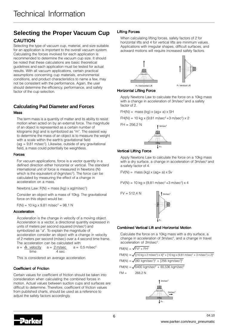
FH: Horizontal Lift FV: Vertical Lift
Horizontal Lifting ForceHorizontal Lifting ForceHorizontal Lifting ForceHorizontal Lifting ForceHorizontal Lifting Force
Apply Newtons Law to calculate the force on a 10kg masswith a change in acceleration of 3m/sec2 and a safetyfactor of 2.
FH(N) = mass (kg) x (ag+ a) x SH
FH(N) = 10 kg x (9,81 m/sec2 +3 m/sec2) x 2
FH = 256,2 N
FH
3m/sec2
10kg
FV
3m/sec2
10kg
FH
3m/sec2
2m/sec2
10kg
Lifting ForcesLifting ForcesLifting ForcesLifting ForcesLifting Forces
When calculating lifting forces, safety factors of 2 forhorizontal lifts and 4 for vertical lifts are minimum values.Applications with irregular shapes, difficult surfaces, andackward motions will require increased safety factors.
VVVVVererererertical Lifting Fortical Lifting Fortical Lifting Fortical Lifting Fortical Lifting Forcecececece
Apply Newtons Law to calculate the force on a 10kg masswith a dry surface, a change in acceleration of 3m/sec2 anda safety factor of 4.
FV(N) = mass (kg) x (ag+ a) x Sv
FV(N) = 10 kg x (9,81 m/sec2 +3 m/sec2) x 4
FV = 512,4 N
Combined VCombined VCombined VCombined VCombined Vererererertical Lift and Horizontal Motiontical Lift and Horizontal Motiontical Lift and Horizontal Motiontical Lift and Horizontal Motiontical Lift and Horizontal Motion
Calculate the force on a 10kg mass with a dry surface, achange in acceleration of 3m/sec2, and a change in travelacceleration of 2m/sec2.
FM(N) = FV2 + FH2
FM(N) = [(10 kg x 2 m/sec2) x 4]2 + [10 kg x (9,81 m/sec2 + 3 m/sec2) x 2]2
FM(N) = (80 kgm/sec2)2 + [256 kgm/sec2]2
FM(N) = 6400 kgm/sec2 + 65,536 kgm/sec2
FM = 268,2 N
7
A
04.10
www.parker.com/euro_pneumatic
Cup Vacuum Level
Diameter Area 10 20 30 40 50 60 70 80 90
[mm] [cm2] [%] [%] [%] [%] [%] [%] [%] [%] [%]
1 0,01 0,01 0,02 0,02 0,03 0,04 0,05 0,06 0,07 0,07
2 0,03 0,03 0,06 0,10 0,13 0,16 0,19 0,22 0,25 0,28
3,5 0,10 0,10 0,20 0,29 0,39 0,49 0,59 0,69 0,78 0,88
5 0,20 0,20 0,40 0,60 0,80 1,00 1,20 1,40 1,60 1,80
6 0,28 0,29 0,58 0,87 1,20 1,40 1,70 2,00 2,30 2,60
7 0,39 0,39 0,78 1,18 1,60 2,00 2,40 2,70 3,10 3,50
8 0,50 0,52 1,02 1,54 2,00 2,60 3,10 3,60 4,10 4,60
10 0,79 0,80 1,60 2,40 3,20 4,00 4,80 5,60 6,40 7,20
15 1,77 1,80 3,60 5,41 7,20 9,00 10,8 12,6 14,4 16,2
18 2,55 2,60 5,20 7,79 10,4 13,0 15,6 18,1 20,8 23,3
20 3,14 3,20 6,40 9,60 12,8 16,0 19,2 22,4 25,6 28,8
25 4,91 5,00 10,0 15,0 20,0 25,0 30,0 35,0 40,0 45,0
30 7,07 7,20 14,4 21,6 28,8 36,0 43,2 50,4 57,6 64,8
35 9,62 9,80 19,6 29,4 39,2 49,0 58,9 68,6 78,5 88,2
40 12,6 12,9 25,6 38,5 51,2 64,0 76,9 89,6 103 115
50 19,6 20,1 40,0 60,1 80,0 100 120 140 160 180
60 28,3 28,9 57,6 86,5 115 144 173 202 231 259
75 44,2 45,2 90,0 135 180 225 270 315 360 405
80 50,3 51,4 102 154 205 256 308 359 410 461
90 63,6 65,1 130 195 259 324 389 454 519 583
95 70,9 72,5 144 217 289 361 434 506 578 650
110 95,0 97,2 194 291 387 484 581 678 775 871
120 113,1 116 230 346 461 576 692 807 922 1037
150 176,7 181 360 541 720 900 1081 1260 1441 1620
200 314,2 321 640 961 1279 1601 1922 2241 2562 2880
Technical Information
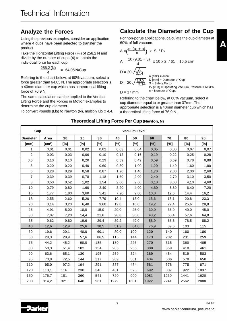
Analyze the ForcesUsing the previous examples, consider an applicationwhere 4 cups have been selected to transfer theproduct.Take the Horizontal Lifting Force (FH) of 256,2 N anddivide by the number of cups (4) to obtain theindividual force for each cup.
256,2 (N) = 64,05 N/Cup4
Refering to the chart below, at 60% vacuum, select aforce greater than 64,05 N. The appropriate selection isa 40mm diameter cup which has a theoretical liftingforce of 76,9 N.The same calculation can be applied to the VerticalLifting Force and the Forces in Motion examples todetermine the cup diameter.To convert Pounds (Lbf) to Newton (N), multiply Lbf x 4,4.
Calculate the Diameter of the CupFor non-porus applications, calculate the cup diameter at60% of full vacuum.
A = m (ag + a) x S / Pv n
A = 10 (9,81 + 3) x 10 x 2 / 61 = 10,5 cm2
4
D = 20 A 3,14
D = 20 10,5 3,14
D = 37 mm
Refering to the chart below, at 60% vacuum, select acup diameter equal to or greater than 37mm. Theappropriate selection is a 40mm diameter cup which hasa theoretical lifting force of 76,9 N.
( )
A (cm2) = AreaD [mm] = Diameter of CupS = Safety FactorPv (kPa) = Operating Vacuum Pressure = 61kPan = Number of Cups
Theoretical Lifting Force Per Cup (Newton, N)

8 04.10
www.parker.com/euro_pneumatic
Technical Information
Material specificationsCup material should be considered for temperatureresistance, chemical resistance, oil resistance,abrasion resistance, markless properties, andelectrical properties.
Suction Cup NBR NBRE CR CRE SI SIE U FKM SH ZMaterial
Name Nitrile Nitrile Chloroprene Chloroprene Silicone Silicone Urethane Viton High Temp. MarklessAnti-Static Anti-Static Anti-Static Material Material
Operating -20 -30 -30 -30 -60 -60 -30 -10 -50 -10Temperature [°C] to +120 to +120 to +140 to +140 to +250 to +250 to +120 to +230 to +300 to +230
Color BlackBlack /
Green Black WhiteBlack /
BlueBlack /
GreyBlack /
Blue Dot Red Dot White Dot Yellow Dot
Hardness,55 ±5 70 ±5 55 ±5 20 ±5 55 ±5 55 ±5 55 ±5 70 ±5 55 ±5 70 ±5Shore A [°Sh]
Electrical—
800—
100— 5 to 15 — — — —Resistance [Ω cm] to 1000 to 1000
WearResistance
• • • • • • • • • • • • • • • • • • • • • • • • • • • • • • • • • • • • • • • •
Tear Strength • • • • • • • • • • • • • • • • • • • • • • • • •
AgingResistance
• • • • • • • • • • • • • • • • • • • • • • • • • • • • • • • • • • • • • • • • • •
OzoneResistance
• • • • • • • • • • • • • • • • • • • • • • • • • • • • • • • • • • • • • • •
GasolineResistance
• • • • • • • • • • • — • • • • • • • • • • • • • • • • • • • • • • •
Oil Resistance • • • • • • • • • • • — • • • • • • • • • • • • • • • • • • • • • • • • • •
Acid Resistance • • • • • • • • • • • • • • • • • • • • • • • • • • • • •
Alkali• • • • • • • • • • • • • • • • • • • • • • • • • • • • • • • •Resistance
Chemical• • • • • • • • • • • • • • • • • • • • • • • • • • • • • •Resistance
Mechanical• • • • • • • • • • • • • • • • • • • • • • • • • • • • • • • • •Resistance
• • • • • • = excellent; • • • • • = very good; • • • • = good; • • • = medium; • • = poor; • = not recommended
Suction Cup in this catalogue are shown in selected material only.Other materials are available on request.
9
A
04.10
www.parker.com/euro_pneumatic
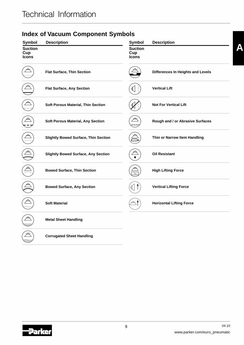
Index of Vacuum Component Symbols
Technical Information
Flat Surface, Thin Section
Flat Surface, Any Section
Soft Porous Material, Thin Section
Soft Porous Material, Any Section
Slightly Bowed Surface, Thin Section
Slightly Bowed Surface, Any Section
Bowed Surface, Thin Section
Bowed Surface, Any Section
Soft Material
Metal Sheet Handling
Corrugated Sheet Handling
Symbol Description
SuctionCupIcons
Differences In Heights and Levels
Vertical Lift
Not For Vertical Lift
Rough and / or Abrasive Surfaces
Thin or Narrow Item Handling
Oil Resistant
High Lifting Force
Vertical Lifting Force
Horizontal Lifting Force
Symbol Description
SuctionCupIcons

10 04.10
www.parker.com/euro_pneumatic
Vacuum Cups PFG
PFG FlatVacuum Cups
PFG Series Vacuum CupsPrecision molded single lip flat cup for smooth or slightlycurved surfaces.
PFTM Series Male ThreadConnectorSimple male connection for low profilepositions secured to a plate or bracket.
Fitting Material: Aluminium.
PFTF Series FemaleThread ConnectorSimple female connection for low profilepositions secured to a plate or bracket.
Fitting Material: Aluminium.
Features• Universal Flat Design for Most Smooth
Surface Applications
• Stable Vertical / Horizontal Lift
• Strong Low Profile Design for FastResponse Needed for Short Cycles
• 1 mm to 200 mm Diameters
ApplicationsExceptional for any smooth flat or surface that will benefit fromstability and fast response of the cup design. This is a multi-versatile and multi-industry cup. Typical applications couldbe chip mounting, electrical components, semiconductorchips, glass, injection mold, sheet metal, press transfer,fixtures, woodworking.
PFTK SeriesBarbed BulkheadTop stem connectors secured with jamnuts and allow tubing connections at thetop side. Nickel plated brass materials.
PFYK Series90° Barbed AdapterSide stem connectors allow you tosecure the stem with a bolt thru a plateor “L” bracket to allow the tubeconnection from the side port. Nickelplated brass materials.
PFTYS Series BulkheadLevel Compensator303 stainless steel construction secured withjam nuts. Spring biased compensators canabsorb impacts of down-strokes and adjustfor different levels of pick up points. 303stainless corrosion resistant materials withdrymet bushings increases the strength andlife.
11 04.10
www.parker.com/euro_pneumatic
A
Vacuum Cups PFG
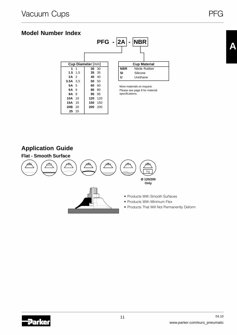
PFG - 2A - NBR
Cup Diameter [mm]1 1 30 30
1.5 1,5 35 352A 2 40 40
3.5A 3,5 50 505A 5 60 606A 6 80 808A 8 95 95
10A 10 120 12015A 15 150 15020B 20 200 200
25 25
Cup MaterialNBR Nitrile RubberSI SiliconeU Urethane
Model Number Index
More materials on request.Please see page 8 for materialspecifications.
Application GuideFlat - Smooth Surface
• Products With Smooth Surfaces
• Products With Minimum Flex
• Products That Will Not Permanently Deform
Ø 120/200Only
12 04.10
www.parker.com/euro_pneumatic
Vacuum Cups PFG
SRV
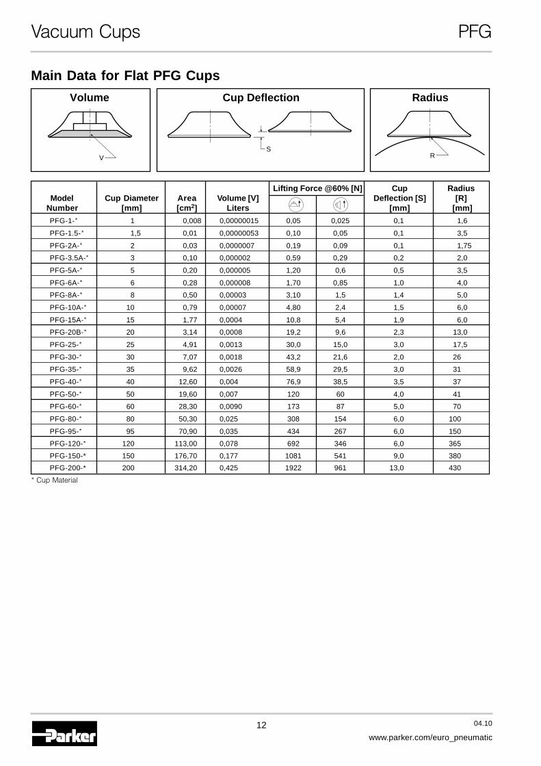
Volume RadiusCup Deflection
Main Data for Flat PFG Cups
Lifting Force @60% [N] Cup RadiusModel Cup Diameter Area Volume [V] Deflection [S] [R]
Number [mm] [cm2] Liters [mm] [mm]
PFG-1-* 1 0,008 0,00000015 0,05 0,025 0,1 1,6
PFG-1.5-* 1,5 0,01 0,00000053 0,10 0,05 0,1 3,5
PFG-2A-* 2 0,03 0,0000007 0,19 0,09 0,1 1,75
PFG-3.5A-* 3 0,10 0,000002 0,59 0,29 0,2 2,0
PFG-5A-* 5 0,20 0,000005 1,20 0,6 0,5 3,5
PFG-6A-* 6 0,28 0,000008 1,70 0,85 1,0 4,0
PFG-8A-* 8 0,50 0,00003 3,10 1,5 1,4 5,0
PFG-10A-* 10 0,79 0,00007 4,80 2,4 1,5 6,0
PFG-15A-* 15 1,77 0,0004 10,8 5,4 1,9 6,0
PFG-20B-* 20 3,14 0,0008 19,2 9,6 2,3 13,0
PFG-25-* 25 4,91 0,0013 30,0 15,0 3,0 17,5
PFG-30-* 30 7,07 0,0018 43,2 21,6 2,0 26
PFG-35-* 35 9,62 0,0026 58,9 29,5 3,0 31
PFG-40-* 40 12,60 0,004 76,9 38,5 3,5 37
PFG-50-* 50 19,60 0,007 120 60 4,0 41
PFG-60-* 60 28,30 0,0090 173 87 5,0 70
PFG-80-* 80 50,30 0,025 308 154 6,0 100
PFG-95-* 95 70,90 0,035 434 267 6,0 150
PFG-120-* 120 113,00 0,078 692 346 6,0 365
PFG-150-* 150 176,70 0,177 1081 541 9,0 380
PFG-200-* 200 314,20 0,425 1922 961 13,0 430
* Cup Material
13 04.10
www.parker.com/euro_pneumatic
A
G H
F
E
BJ
D
AC
FA
DJB
C
EGH
PFG-2APFG-2APFG-2APFG-2APFG-2A
PFG-3.5APFG-3.5APFG-3.5APFG-3.5APFG-3.5APFG-5APFG-5APFG-5APFG-5APFG-5A
PFG-15APFG-15APFG-15APFG-15APFG-15A
PFG-60 thruPFG-60 thruPFG-60 thruPFG-60 thruPFG-60 thru
PFG-95PFG-95PFG-95PFG-95PFG-95PFG-120 thruPFG-120 thruPFG-120 thruPFG-120 thruPFG-120 thruPFG-200PFG-200PFG-200PFG-200PFG-200
H
AC
BD
F
E H
AC
B
D
F
E
A
E
H
F
B
D
A
BD
G
C
E
H
F
PFG-20B thruPFG-20B thruPFG-20B thruPFG-20B thruPFG-20B thruPFG-40PFG-40PFG-40PFG-40PFG-40
Vacuum Cups PFG
PFG-1PFG-1PFG-1PFG-1PFG-1
PFG-1.5PFG-1.5PFG-1.5PFG-1.5PFG-1.5
A
E
C
D
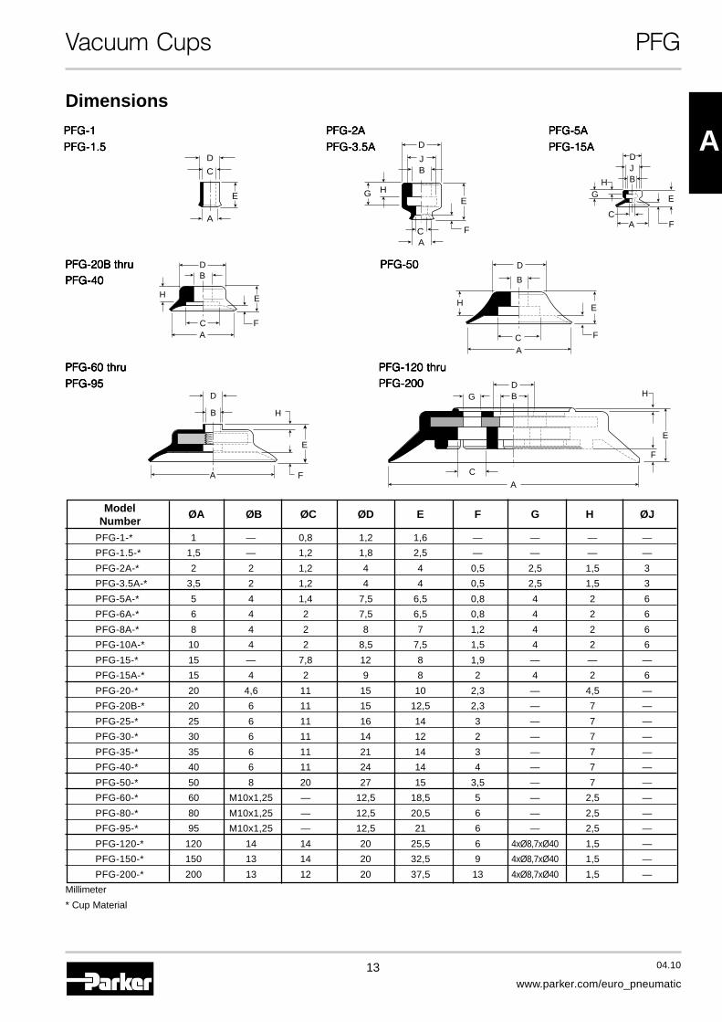
Dimensions
PFG-50PFG-50PFG-50PFG-50PFG-50
Model ØA ØB ØC ØD E F G H ØJNumber
PFG-1-* 1 — 0,8 1,2 1,6 — — — —
PFG-1.5-* 1,5 — 1,2 1,8 2,5 — — — —
PFG-2A-* 2 2 1,2 4 4 0,5 2,5 1,5 3
PFG-3.5A-* 3,5 2 1,2 4 4 0,5 2,5 1,5 3
PFG-5A-* 5 4 1,4 7,5 6,5 0,8 4 2 6
PFG-6A-* 6 4 2 7,5 6,5 0,8 4 2 6
PFG-8A-* 8 4 2 8 7 1,2 4 2 6
PFG-10A-* 10 4 2 8,5 7,5 1,5 4 2 6
PFG-15-* 15 — 7,8 12 8 1,9 — — —
PFG-15A-* 15 4 2 9 8 2 4 2 6
PFG-20-* 20 4,6 11 15 10 2,3 — 4,5 —
PFG-20B-* 20 6 11 15 12,5 2,3 — 7 —
PFG-25-* 25 6 11 16 14 3 — 7 —
PFG-30-* 30 6 11 14 12 2 — 7 —
PFG-35-* 35 6 11 21 14 3 — 7 —
PFG-40-* 40 6 11 24 14 4 — 7 —
PFG-50-* 50 8 20 27 15 3,5 — 7 —
PFG-60-* 60 M10x1,25 — 12,5 18,5 5 — 2,5 —
PFG-80-* 80 M10x1,25 — 12,5 20,5 6 — 2,5 —
PFG-95-* 95 M10x1,25 — 12,5 21 6 — 2,5 —
PFG-120-* 120 14 14 20 25,5 6 4xØ8,7xØ40 1,5 —
PFG-150-* 150 13 14 20 32,5 9 4xØ8,7xØ40 1,5 —
PFG-200-* 200 13 12 20 37,5 13 4xØ8,7xØ40 1,5 —
Millimeter
* Cup Material

14 04.10
www.parker.com/euro_pneumatic
Cup MaterialNBR Nitrile
RubberSI SiliconeU Urethane
Model Number Index
PFG Cup Diameter [mm] FTM Fitting Part Number Mounting Thread
2AFTM-2A-M5 M5x0,8 Male
3.5A
5A6A8A FTM-5A-M5 M5x0,8 Male
10A FTM-5A-G1 1/8 BSPP Male15A
20B2530 FTM-20B-G1 1/8 BSPP Male35 FTM-20B-G2 1/4 BSPP Male40
FTM-50-G1 1/8 BSPP Male50
FTM-50-G2 1/4 BSPP Male
6080 FTM-60-G2 1/4 BSPP Male95
Vacuum Cup Assemblies PFTM
Male Thread Fitting for PFG Cups
PFTM Vacuum Cup Assemblies
MountingThread
M5 M5G1 1/8 BSPPG2 1/4 BSPP
See ChartBelow
PFTM - 2A - NBR - M5
MountingThread
InstallationNote:When installing cup assemblies,use a sealant material to securethe assembly and preventvacuum leakage.
Cup Diameter [mm]2A 2 25 25
3.5A 3,5 30 305A 5 35 356A 6 40 408A 8 50 50
10A 10 60 6015A 15 80 8020B 20 95 95
More materials on request.Please see page 8 formaterial specifications.
15 04.10
www.parker.com/euro_pneumatic
APFTM-2A thruPFTM-2A thruPFTM-2A thruPFTM-2A thruPFTM-2A thru
PFTM-15APFTM-15APFTM-15APFTM-15APFTM-15A
PFTM-20B thruPFTM-20B thruPFTM-20B thruPFTM-20B thruPFTM-20B thruPFTM-50PFTM-50PFTM-50PFTM-50PFTM-50
PFTM-60 thruPFTM-60 thruPFTM-60 thruPFTM-60 thruPFTM-60 thru
PFTM-95PFTM-95PFTM-95PFTM-95PFTM-95
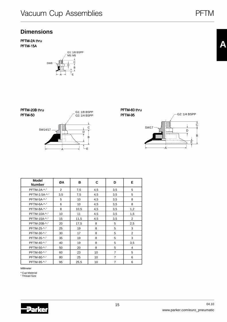
Model ØA B C D ENumber
PFTM-2A-*-† 2 7,5 4,5 3,5 5
PFTM-3.5A-*-† 3,5 7,5 4,5 3,5 5
PFTM-5A-*-† 5 10 4,5 3,5 8
PFTM-6A-*-† 6 10 4,5 3,5 8
PFTM-8A-*-† 8 10,5 4,5 3,5 1,2
PFTM-10A-*-† 10 11 4,5 3,5 1,5
PFTM-15A-*-† 15 11,5 4,5 3,5 2
PFTM-20B-*-† 20 17,5 8 5 2,5
PFTM-25-*-† 25 19 8 5 3
PFTM-30-*-† 30 17 8 5 2
PFTM-35-*-† 35 19 8 5 3
PFTM-40-*-† 40 19 8 5 3,5
PFTM-50-*-† 50 20 8 5 4
PFTM-60-*-† 60 23 10 7 5
PFTM-80-*-† 80 25 10 7 6
PFTM-95-*-† 95 25,5 10 7 6
Vacuum Cup Assemblies PFTM
Dimensions
A
B
C
D
E
G2: 1/4 BSPP
SW17
G1: 1/8 BSPPG2: 1/4 BSPP
SW14/17
A E
B
C
D
SW8
G1: 1/8 BSPPM5: M5
E
B
CD
A
Millimeter
* Cup Material† Thread Size

16 04.10
www.parker.com/euro_pneumatic
Vacuum Cup Assemblies PFTF
Cup Diameter [mm]5A 5 40 406A 6 50 508A 8 60 60
10A 10 80 8015A 15 95 9520B 20 120 120
25 25 150 15030 30 200 20035 35
Cup MaterialNBR Nitrile
RubberSI SiliconeU Urethane
Model Number Index
PFG Cup Diameter [mm] FTF Fitting Part Number Mounting Thread5A6A8A FTF-5A-M5 M5x0,8 Female
10A FTF-5A-G1 1/8 BSPP Female15A20B
2530 FTF-20B-G1 1/8 BSPP Female35 FTF-20B-G2 1/4 BSPP Female40
50FTF-50-G1 1/8 BSPP FemaleFTF-50-G2 1/4 BSPP Female
6080 FTF-60-G2 1/4 BSPP Female95
120150 FTF-120-G4 1/2 BSPP Female200
Female Thread Fitting for PFG Cups
PFTF Vacuum Cup AssembliesPFTF - 5A - NBR - M5
MountingThread
MountingThread
Installation
Note:Note:Note:Note:Note:When installing cup assemblies, use a sealant material tosecure the assembly and prevent vacuum leakage.
Millimeter
MountingThread
M5 M5G1 1/8 BSPPG2 1/4 BSPPG4 1/2 BSPP
See ChartBelow
More materials on request.Please see page 8 formaterial specifications.
17 04.10
www.parker.com/euro_pneumatic
A
Vacuum Cup Assemblies PFTF
PFTF-5A thruPFTF-5A thruPFTF-5A thruPFTF-5A thruPFTF-5A thru
PFTF-15APFTF-15APFTF-15APFTF-15APFTF-15A
PFTF-60 thruPFTF-60 thruPFTF-60 thruPFTF-60 thruPFTF-60 thru
PFTF-95PFTF-95PFTF-95PFTF-95PFTF-95
PFTF-120 thruPFTF-120 thruPFTF-120 thruPFTF-120 thruPFTF-120 thru
PFTF-200PFTF-200PFTF-200PFTF-200PFTF-200
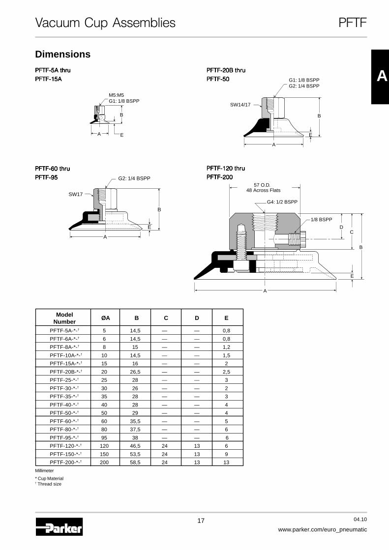
Model ØA B C D ENumber
PFTF-5A-*-† 5 14,5 — — 0,8
PFTF-6A-*-† 6 14,5 — — 0,8
PFTF-8A-*-† 8 15 — — 1,2
PFTF-10A-*-† 10 14,5 — — 1,5
PFTF-15A-*-† 15 16 — — 2
PFTF-20B-*-† 20 26,5 — — 2,5
PFTF-25-*-† 25 28 — — 3
PFTF-30-*-† 30 26 — — 2
PFTF-35-*-† 35 28 — — 3
PFTF-40-*-† 40 28 — — 4
PFTF-50-*-† 50 29 — — 4
PFTF-60-*-† 60 35,5 — — 5
PFTF-80-*-† 80 37,5 — — 6
PFTF-95-*-† 95 38 — — 6
PFTF-120-*-† 120 46,5 24 13 6
PFTF-150-*-† 150 53,5 24 13 9
PFTF-200-*-† 200 58,5 24 13 13
Millimeter
* Cup Material† Thread size
A
B
E
G2: 1/4 BSPP
SW17
A
G4: 1/2 BSPP
1/8 BSPP
B
D
E
C
57 O.D. 48 Across Flats
Dimensions
PFTF-20B thruPFTF-20B thruPFTF-20B thruPFTF-20B thruPFTF-20B thru
PFTF-50PFTF-50PFTF-50PFTF-50PFTF-50 G1: 1/8 BSPPG2: 1/4 BSPP
SW14/17
A
E
B
EA
M5:M5G1: 1/8 BSPP
B
18 04.10
www.parker.com/euro_pneumatic
Vacuum Cup Assemblies PFTK
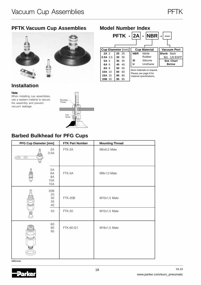
Model Number IndexPFTK Vacuum Cup Assemblies
PFTK - 2A - NBR - —
Barbed Bulkhead for PFG Cups
Installation
MountingThread
CupScrew
Note:Note:Note:Note:Note:When installing cup assemblies,use a sealant material to securethe assembly and preventvacuum leakage.
Millimeter
PFG Cup Diameter [mm] FTK Part Number Mounting Thread
2A FTK-2A M5x0,5 Male3.5A
5A6A FTK-5A M9x1,0 Male8A
10A15A
20B2530 FTK-20B M10x1,5 Male3540
50 FTK-50 M10x1,5 Male
6080 FTK-60-G1 M16x1,5 Male95
Cup Diameter [mm]2A 2 25 25
3.5A 3,5 30 305A 5 35 356A 6 40 408A 8 50 50
10A 10 60 6015A 15 80 8020B 20 95 95
Cup MaterialNBR Nitrile
RubberSI SiliconeU Urethane
Vacuum PortBlank Barb
G1 1/8 BSPPSee Chart
Below
More materials on request.Please see page 8 formaterial specifications.
19 04.10
www.parker.com/euro_pneumatic
A
20 105
A
SW7
M5
BD
C
E
2
Ø 1,2
Ø 2,5
Ø 5,52 Places
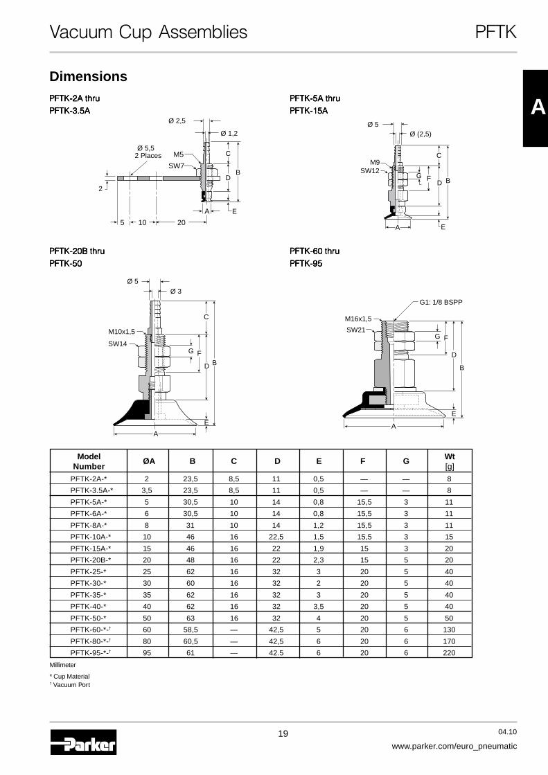
Vacuum Cup Assemblies PFTK
PFTK-2A thruPFTK-2A thruPFTK-2A thruPFTK-2A thruPFTK-2A thru
PFTK-3.5APFTK-3.5APFTK-3.5APFTK-3.5APFTK-3.5APFTK-5A thruPFTK-5A thruPFTK-5A thruPFTK-5A thruPFTK-5A thru
PFTK-15APFTK-15APFTK-15APFTK-15APFTK-15A
Model ØA B C D E F G WtNumber [g]
PFTK-2A-* 2 23,5 8,5 11 0,5 — — 8
PFTK-3.5A-* 3,5 23,5 8,5 11 0,5 — — 8
PFTK-5A-* 5 30,5 10 14 0,8 15,5 3 11
PFTK-6A-* 6 30,5 10 14 0,8 15,5 3 11
PFTK-8A-* 8 31 10 14 1,2 15,5 3 11
PFTK-10A-* 10 46 16 22,5 1,5 15,5 3 15
PFTK-15A-* 15 46 16 22 1,9 15 3 20
PFTK-20B-* 20 48 16 22 2,3 15 5 20
PFTK-25-* 25 62 16 32 3 20 5 40
PFTK-30-* 30 60 16 32 2 20 5 40
PFTK-35-* 35 62 16 32 3 20 5 40
PFTK-40-* 40 62 16 32 3,5 20 5 40
PFTK-50-* 50 63 16 32 4 20 5 50
PFTK-60-*-† 60 58,5 — 42,5 5 20 6 130
PFTK-80-*-† 80 60,5 — 42,5 6 20 6 170
PFTK-95-*-† 95 61 — 42.5 6 20 6 220
Millimeter
* Cup Material† Vacuum Port
Ø 5Ø (2,5)
FG
C
D B
E
M9SW12
A
PFTK-60 thruPFTK-60 thruPFTK-60 thruPFTK-60 thruPFTK-60 thru
PFTK-95PFTK-95PFTK-95PFTK-95PFTK-95
A
G1: 1/8 BSPP
SW21
M16x1,5
B
FG
D
E
Dimensions
PFTK-20B thruPFTK-20B thruPFTK-20B thruPFTK-20B thruPFTK-20B thru
PFTK-50PFTK-50PFTK-50PFTK-50PFTK-50
A
BFG
C
D
E
M10x1,5
SW14
Ø 5Ø 3

20 04.10
www.parker.com/euro_pneumatic
Vacuum Cup Assemblies PFYK
90° Barbed Adapter for PFG Cups
PFYK Vacuum Cup Assemblies
MountingThread
Cup Screw
InstallationNote:Note:Note:Note:Note:When installing cup assemblies,use a sealant material to securethe assembly and preventvacuum leakage.
Millimeter
Model Number IndexPFYK - 5A - NBR - —
Cup Diameter [mm]2A 2 35 35
3.5A 2 40 405A 5 50 506A 6 60 608A 8 80 80
10A 10 95 9515A 15 120 12020B 20 150 150
25 25 200 20030 30
Vacuum PortBlank Barb
G1 1/8 BSPPSee Chart
Below
Cup MaterialNBR Nitrile
RubberSI SiliconeU Urethane
PFG Cup Diameter [mm] FYK Part Number Mounting Thread
2AFYK-2A M3x0,5 Female
3.5A
5A
6AFYK-5A M4x0,7 Female
8A
10A
15A
20B
25
30 FYK-20B M6x1,0 Female
35
40
50 FYK-50 M6x1,0 Female
60
80 FYK-60-G1 M8x1,25 Female
95
120
150 FYK-120-G1 M16x1,5 Female
200
More materials on request.Please see page 8 formaterial specifications.

21 04.10
www.parker.com/euro_pneumatic
A
Vacuum Cup Assemblies PFYK
PFYK-2A thruPFYK-2A thruPFYK-2A thruPFYK-2A thruPFYK-2A thru
PFYK-3.5APFYK-3.5APFYK-3.5APFYK-3.5APFYK-3.5A
PFYK-60 thruPFYK-60 thruPFYK-60 thruPFYK-60 thruPFYK-60 thruPFYK-95PFYK-95PFYK-95PFYK-95PFYK-95
Model ØA B C D E F G WtNumber [g]
PFYK-2A-* 2 20 11 16 0,5 0,5 8,5 3
PFYK-3.5A-* 3,5 20 11 16 0,5 0,5 8,5 3
PFYK-5A-* 5 29 13 22,5 0,8 6 16 16
PFYK-6A-* 6 29 13 22,5 0,8 6 16 16
PFYK-8A-* 8 29,5 13 22,5 1,2 6 16 16
PFYK-10A-* 10 30 13 22,5 1,5 6 16 16
PFYK-15A-* 15 30 14 22 1,9 6 16 20
PFYK-20B-* 20 32 14 22 2,3 6 16 20
PFYK-25-* 25 46 20 32 3 8 16 40
PFYK-30-* 30 44 20 32 2 8 16 40
PFYK-35-* 35 46 20 32 3 8 16 40
PFYK-40-* 40 46 20 32 3,5 8 16 50
PFYK-50-* 50 47 20 32 4 8 16 55
PFYK-60-*-† 60 58,5 28 40 5 11 — 120
PFYK-80-*-† 80 60,5 28 40 6 11 — 160
PFYK-95-*-† 95 61 28 40 6 11 — 210
PFYK-120-*-† 120 75,5 12 50 6 20 Ø 30 640
PFYK-150-*-† 150 82,5 12 50 9 20 Ø 30 910
PFYK-200-*-† 200 87,5 12 50 13 20 Ø 30 1200
Millimeter* Cup Material† Vacuum Port
PFYK-5A thruPFYK-5A thruPFYK-5A thruPFYK-5A thruPFYK-5A thru
PFYK-15APFYK-15APFYK-15APFYK-15APFYK-15A
A
M3x0,5
BDC
F
G
E
Ø 1
,2
Ø 2
,5
FC
DB
EØ
5
Ø 3
M4x0,7G
A
PFYK-20B thruPFYK-20B thruPFYK-20B thruPFYK-20B thruPFYK-20B thruPFYK-50PFYK-50PFYK-50PFYK-50PFYK-50
B
F
GM6x1,0
C
D
E
Ø 5
Ø 3
A A
M8x1,25
B
F
G1: 1/8 BSPP
C
D
E
A
Ø 70(SW65)
G
M16
G1: 1/8 BSPP
M8x1,25
BC
D
E
F
Dimensions
PFYK-120 thruPFYK-120 thruPFYK-120 thruPFYK-120 thruPFYK-120 thruPFYK-200PFYK-200PFYK-200PFYK-200PFYK-200

22 04.10
www.parker.com/euro_pneumatic
Vacuum Cup Assemblies PFTYS
Bulkhead Level Compensator for PFG Cups
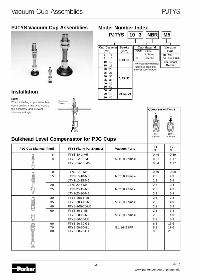
PFTYS Vacuum Cup Assemblies
Installation
MountingThread
Note:Note:Note:Note:Note:When installing cup assemblies,use a sealant material to securethe assembly and preventvacuum leakage.
Cup Diameter Stroke[mm] [mm]
2A 23.5A 3,5
5A 56A 6 3, 10, 158A 8
10A 1015A 1520B 20
25 2530 30
6, 15, 3035 3540 4050 5060 6080 80 30, 50, 7095 95
120 120150 150 20, 70200 200
Cup MaterialNBR Nitrile
RubberSI SiliconeU Urethane
Model Number Index
PFTYS 2A 15 NBR M3
VacuumPort
M3 M3M5 M5G1 1/8 BSPPG2 1/4 BSPPSee Chart
Below
PFG Cup Diameter [mm] FTYS Part Number Vacuum PortsF1 F2N N
2AFTYS-2A-3-M3 0,49 0,59
3.5AFTYS-2A-10-M3 M3x0,5 Female 0,49 0,59FTYS-2A-15-M3 0,49 0,59
5A6A FTYS-5A-3-M5 0,49 0,598A FTYS-5A-10-M5 M5x0,8 Female 0,61 1,17
10A FTYS-5A-15-M5 0,64 1,1715A20B
25 FTYS-20B-6-M5 2,5 3,430 FTYS-20B-15-M5 M5x0,8 Female 2,5 4,935 FTYS-20B-30-M5 2,9 5,94050 FTYS-50-6-M5 2,5 3,4
FTYS-50-15-M5 M5x0,8 Female 2,5 4,9FTYS-50-30-M5 2,9 5,9
60 FTYS-60-30-G1 6,8 15,680 FTYS-60-50-G1 G1: 1/8 BSPP 8,3 19,695 FTYS-60-70-G1 9,5 21
12015,6 29
150FTYS-120-20-G2
G2: 1/4 BSPP14,7 29
200FTYS-120-70-G2
Compression ForceF1
0%of Stroke
100%of Stroke
F2
More materials on request.Please see page 8 formaterial specifications.

23 04.10
www.parker.com/euro_pneumatic
A
Vacuum Cup Assemblies PFTYS
PFTYS5A3 thruPFTYS5A3 thruPFTYS5A3 thruPFTYS5A3 thruPFTYS5A3 thru
PFTYS15A15PFTYS15A15PFTYS15A15PFTYS15A15PFTYS15A15PFTYS2A3 thruPFTYS2A3 thruPFTYS2A3 thruPFTYS2A3 thruPFTYS2A3 thru
PFTYS3.5A15PFTYS3.5A15PFTYS3.5A15PFTYS3.5A15PFTYS3.5A15
Dimensions
M3x0,5
M3x0,5
SW6
SW12
M8x0,75
B
D C
F
9
H
G
EA
M5x0,8
M5x0,8
SW6
SW12
M8x0,75
B
D C
F
9
H
G
EA
Model ØA B C D E F G H WtNumber [g]
PFTYS2A3*† 2 50 11 7 0,5 3 3 23 6
PFTYS2A10*† 2 57 11 7 0,5 10 3 23 11
PFTYS2A15*† 2 69,5 11 7 0,5 15 3 30,5 15
PFTYS3.5A3*† 3,5 50 11 7 0,5 3 3 23 6
PFTYS3.5A10*† 3,5 57 11 7 0,5 10 3 23 11
PFTYS3.5A15*† 3,5 69,5 11 7 0,5 15 3 30,5 15
PFTYS5A3*† 5 54 13 8 0,8 3 3 23 7
PFTYS5A10*† 5 61,5 13 8 0,8 10 3 23 18,5
PFTYS5A15*† 5 74 13 8 0,8 15 3 30,5 21
PFTYS6A3*† 6 54,5 13 8 0,8 3 3 23 7
PFTYS6A10*† 6 61,5 13 8 0,8 10 3 23 18,5
PFTYS6A15*† 6 74 13 8 0,8 15 3 30,5 21
PFTYS8A3*† 8 55,5 13 8 1,2 3 3 23 7
PFTYS8A10*† 8 62 13 8 1,2 10 3 23 18,5
PFTYS8A15*† 8 74,5 13 8 1,2 15 3 30,5 21
PFTYS10A3*† 10 54 13 8 1,5 3 3 23 18
PFTYS10A10*† 10 63 13 8 1,5 10 3 23 18,5
PFTYS10A15*† 10 75 13 8 1,5 15 3 30,5 21
PFTYS15A3*† 15 56 13 8 2 3 3 23 18
PFTYS15A10*† 15 63,5 13 8 2 10 3 23 18,5
PFTYS15A15*† 15 75,5 13 8 2 15 3 30,5 21
Millimeter* Cup Material† Vacuum Port
24 04.10
www.parker.com/euro_pneumatic
Vacuum Cup Assemblies PFTYS
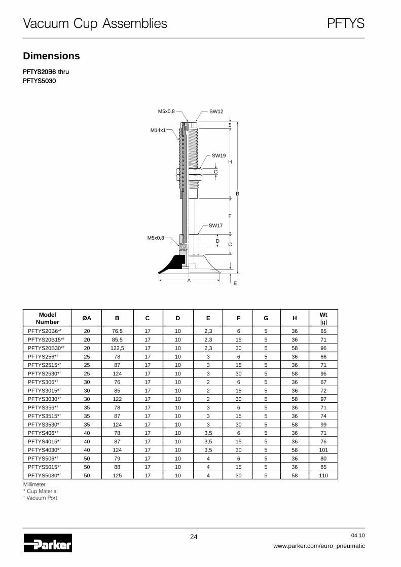
PFTYS20B6 thruPFTYS20B6 thruPFTYS20B6 thruPFTYS20B6 thruPFTYS20B6 thru
PFTYS5030PFTYS5030PFTYS5030PFTYS5030PFTYS5030
Dimensions
M5x0,8 SW12
SW19
SW17
M14x1
M5x0,8
B
D
E
C
H
5
F
G
A
Model ØA B C D E F G H WtNumber [g]
PFTYS20B6*† 20 76,5 17 10 2,3 6 5 36 65
PFTYS20B15*† 20 85,5 17 10 2,3 15 5 36 71
PFTYS20B30*† 20 122,5 17 10 2,3 30 5 58 96
PFTYS256*† 25 78 17 10 3 6 5 36 66
PFTYS2515*† 25 87 17 10 3 15 5 36 71
PFTYS2530*† 25 124 17 10 3 30 5 58 96
PFTYS306*† 30 76 17 10 2 6 5 36 67
PFTYS3015*† 30 85 17 10 2 15 5 36 72
PFTYS3030*† 30 122 17 10 2 30 5 58 97
PFTYS356*† 35 78 17 10 3 6 5 36 71
PFTYS3515*† 35 87 17 10 3 15 5 36 74
PFTYS3530*† 35 124 17 10 3 30 5 58 99
PFTYS406*† 40 78 17 10 3,5 6 5 36 71
PFTYS4015*† 40 87 17 10 3,5 15 5 36 76
PFTYS4030*† 40 124 17 10 3,5 30 5 58 101
PFTYS506*† 50 79 17 10 4 6 5 36 80
PFTYS5015*† 50 88 17 10 4 15 5 36 85
PFTYS5030*† 50 125 17 10 4 30 5 58 110
Millimeter* Cup Material† Vacuum Port
25 04.10
www.parker.com/euro_pneumatic
A
Vacuum Cup Assemblies PFTYS
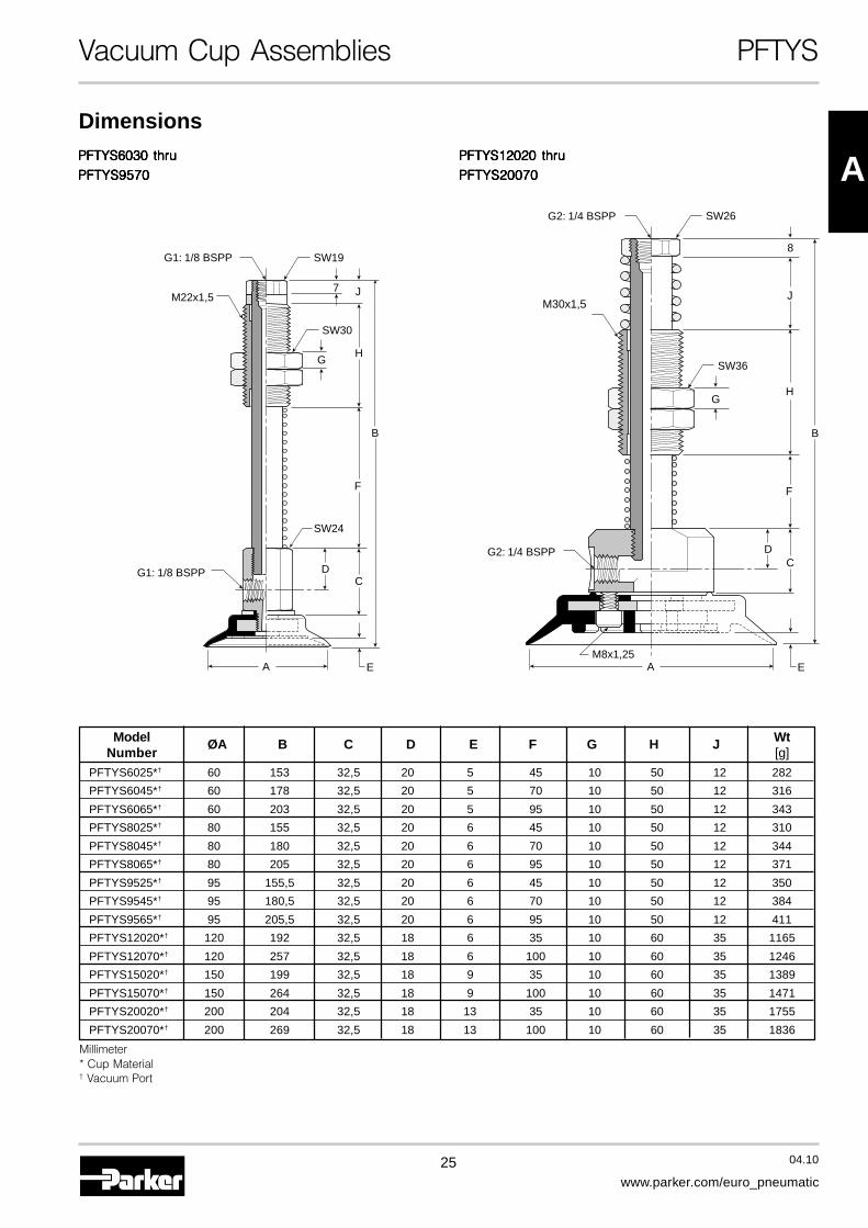
PFTYS12020 thruPFTYS12020 thruPFTYS12020 thruPFTYS12020 thruPFTYS12020 thru
PFTYS20070PFTYS20070PFTYS20070PFTYS20070PFTYS20070PFTYS6030 thruPFTYS6030 thruPFTYS6030 thruPFTYS6030 thruPFTYS6030 thru
PFTYS9570PFTYS9570PFTYS9570PFTYS9570PFTYS9570
Dimensions
G1: 1/8 BSPP
G1: 1/8 BSPP
SW19
SW30
SW24
M22x1,5
B
D
A E
C
H
J7
F
G
A
G2: 1/4 BSPP
G2: 1/4 BSPP
M8x1,25
SW26
SW36
M30x1,5
B
D
E
C
J
8
F
HG
Model ØA B C D E F G H J WtNumber [g]
PFTYS6025*† 60 153 32,5 20 5 45 10 50 12 282
PFTYS6045*† 60 178 32,5 20 5 70 10 50 12 316
PFTYS6065*† 60 203 32,5 20 5 95 10 50 12 343
PFTYS8025*† 80 155 32,5 20 6 45 10 50 12 310
PFTYS8045*† 80 180 32,5 20 6 70 10 50 12 344
PFTYS8065*† 80 205 32,5 20 6 95 10 50 12 371
PFTYS9525*† 95 155,5 32,5 20 6 45 10 50 12 350
PFTYS9545*† 95 180,5 32,5 20 6 70 10 50 12 384
PFTYS9565*† 95 205,5 32,5 20 6 95 10 50 12 411
PFTYS12020*† 120 192 32,5 18 6 35 10 60 35 1165
PFTYS12070*† 120 257 32,5 18 6 100 10 60 35 1246
PFTYS15020*† 150 199 32,5 18 9 35 10 60 35 1389
PFTYS15070*† 150 264 32,5 18 9 100 10 60 35 1471
PFTYS20020*† 200 204 32,5 18 13 35 10 60 35 1755
PFTYS20070*† 200 269 32,5 18 13 100 10 60 35 1836
Millimeter* Cup Material† Vacuum Port

26 04.10
www.parker.com/euro_pneumatic
Vacuum Cups & Assemblies PFG, PFTK, PFYK
PFG OvalVacuum Cups
Dimensions
ApplicationsThese suction cups are for applications where insufficientsurface areas are available for standard round PFG cups tosecure vacuum for transfer. The oval or rectangular designallows you to maximize the available space to properly lift theproduct in high speed automation. These cups are non-rotational.
Model ØA ØA1 ØB ØC ØD E F G HNumber
PFG-2x4A 4 2 2,6 1,2 6 6 0,5 3,5 2,5
PFG-3.5Ax7A 7 3,5 2,6 1,5 6 6 0,8 3,5 2,5
Millimeter
Model Number Index
Cup Diameter [mm]2x4A 2x4
3.5x7A 3,5x7
Cup MaterialNBR Nitrile RubberNBRE Nitrile Anti-StaticSI SiliconeSIE Silicone Anti-Static
PFG - 2x4A - NBR
PFGPFGPFGPFGPFG -3.5x7A-3.5x7A-3.5x7A-3.5x7A-3.5x7A
A
D
A1
G HE
FC
B
PFG-2x4APFG-2x4APFG-2x4APFG-2x4APFG-2x4A
A
D
A1
EG H
FC
B
PFYK Vacuum Cup Assemblies
Model Number Index
Cup Diameter2x4A
3.5x7A
Cup MaterialNBR Nitrile RubberNBRE Nitrile ESDSI SiliconeSIE Silicone ESD
PFYK - 2x4A - NBR
PFTK Vacuum Cup Assemblies
Model Number Index
Cup Diameter2x4A
3.5x7A
Cup MaterialNBR Nitrile RubberNBRE Nitrile ESDSI SiliconeSIE Silicone ESD
PFTK - 2x4A - NBR
More materials on request.Please see page 8 formaterial specifications.
More materials on request.Please see page 8 formaterial specifications.
More materials on request.Please see page 8 formaterial specifications.
27 04.10
www.parker.com/euro_pneumatic
A
Vacuum Cups & Assemblies PFG, PFTK, PFYK
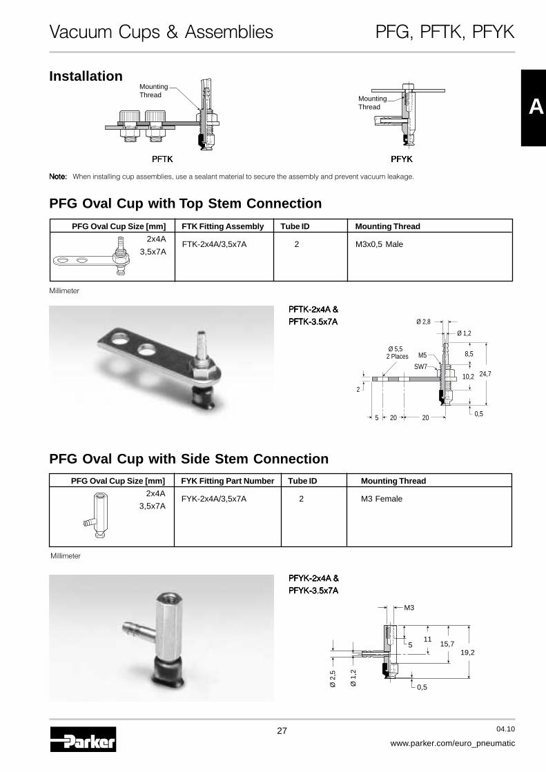
PFG Oval Cup with Top Stem Connection
PFG Oval Cup with Side Stem Connection
PFYK-2x4A &PFYK-2x4A &PFYK-2x4A &PFYK-2x4A &PFYK-2x4A &
PFYK-3.5x7APFYK-3.5x7APFYK-3.5x7APFYK-3.5x7APFYK-3.5x7A
20
24,7
8,5
10,2
0,5205
SW7
M5
2
Ø 1,2
Ø 2,8
Ø 5,52 Places
M3
Ø 1
,2
Ø 2
,5
19,2
1115,75
0,5
Installation
Note:Note:Note:Note:Note: When installing cup assemblies, use a sealant material to secure the assembly and prevent vacuum leakage.
MountingThread
MountingThread
PFTKPFTKPFTKPFTKPFTK PFYKPFYKPFYKPFYKPFYK
Millimeter
Millimeter
PFG Oval Cup Size [mm] FTK Fitting Assembly Tube ID Mounting Thread
2x4AFTK-2x4A/3,5x7A 2 M3x0,5 Male
3,5x7A
PFTK-2x4A &PFTK-2x4A &PFTK-2x4A &PFTK-2x4A &PFTK-2x4A &
PFTK-3.5x7APFTK-3.5x7APFTK-3.5x7APFTK-3.5x7APFTK-3.5x7A
PFG Oval Cup Size [mm] FYK Fitting Part Number Tube ID Mounting Thread
2x4AFYK-2x4A/3,5x7A 2 M3 Female
3,5x7A
28 04.10
www.parker.com/euro_pneumatic
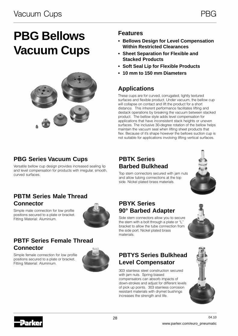
Features• Bellows Design for Level Compensation
Within Restricted Clearances• Sheet Separation for Flexible and
Stacked Products• Soft Seal Lip for Flexible Products• 10 mm to 150 mm Diameters
ApplicationsThese cups are for curved, corrugated, lightly texturedsurfaces and flexible product. Under vacuum, the bellow cupwill collapse on contact and lift the product for a shortdistance. This inherent performance facilitates lifting anddestack operations by breaking the vacuum between stackedproduct. The bellow style adds level compensation forapplications that have inconsistent stack heights or unevensurfaces. The inclusive 30-degree rotation of the bellow helpsmaintain the vacuum seal when lifting sheet products thatflex. Because of it’s shape however the bellows suction cup isnot suitable for applications involving lifting vertical surfaces.
PBG Series Vacuum CupsVersatile bellow cup design provides increased sealing lipand level compensation for products with irregular, smooth,curved surfaces.
PBTM Series Male ThreadConnectorSimple male connection for low profilepositions secured to a plate or bracket.Fitting Material: Aluminium.
PBTF Series Female ThreadConnectorSimple female connection for low profilepositions secured to a plate or bracket.Fitting Material: Aluminium.
PBTK SeriesBarbed BulkheadTop stem connectors secured with jam nutsand allow tubing connections at the topside. Nickel plated brass materials.
PBYK Series90° Barbed AdapterSide stem connectors allow you to securethe stem with a bolt through a plate or “L”bracket to allow the tube connection fromthe side port. Nickel plated brassmaterials.
PBTYS Series BulkheadLevel Compensator303 stainless steel construction securedwith jam nuts. Spring biasedcompensators can absorb impacts ofdown-strokes and adjust for different levelsof pick up points. 303 stainless corrosionresistant materials with drymet bushingsincreases the strength and life.
PBG BellowsVacuum Cups
Vacuum Cups PBG
29 04.10
www.parker.com/euro_pneumatic
A
Vacuum Cups PBG
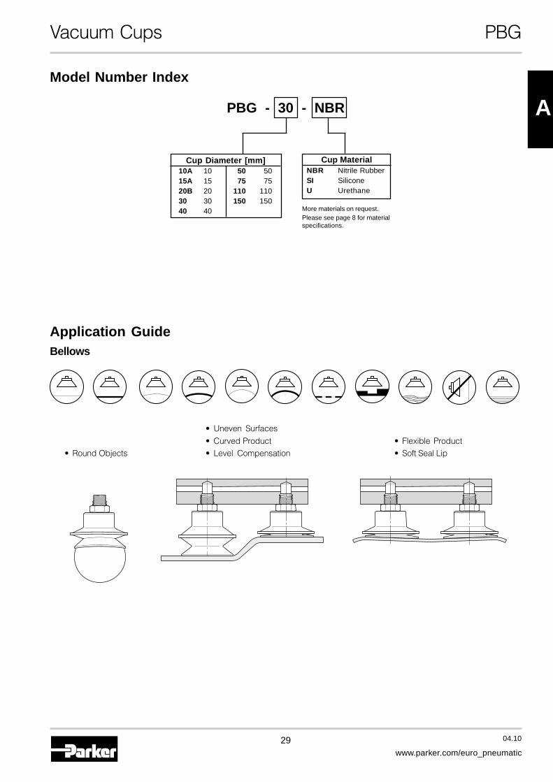
Model Number Index
PBG - 30 - NBR
Cup Diameter [mm]10A 10 50 5015A 15 75 7520B 20 110 11030 30 150 15040 40
Cup MaterialNBR Nitrile RubberSI SiliconeU Urethane
More materials on request.Please see page 8 for materialspecifications.
Application GuideBellows
• Round Objects
• Uneven Surfaces
• Curved Product• Level Compensation
• Flexible Product• Soft Seal Lip
30 04.10
www.parker.com/euro_pneumatic
Vacuum Cups PBG
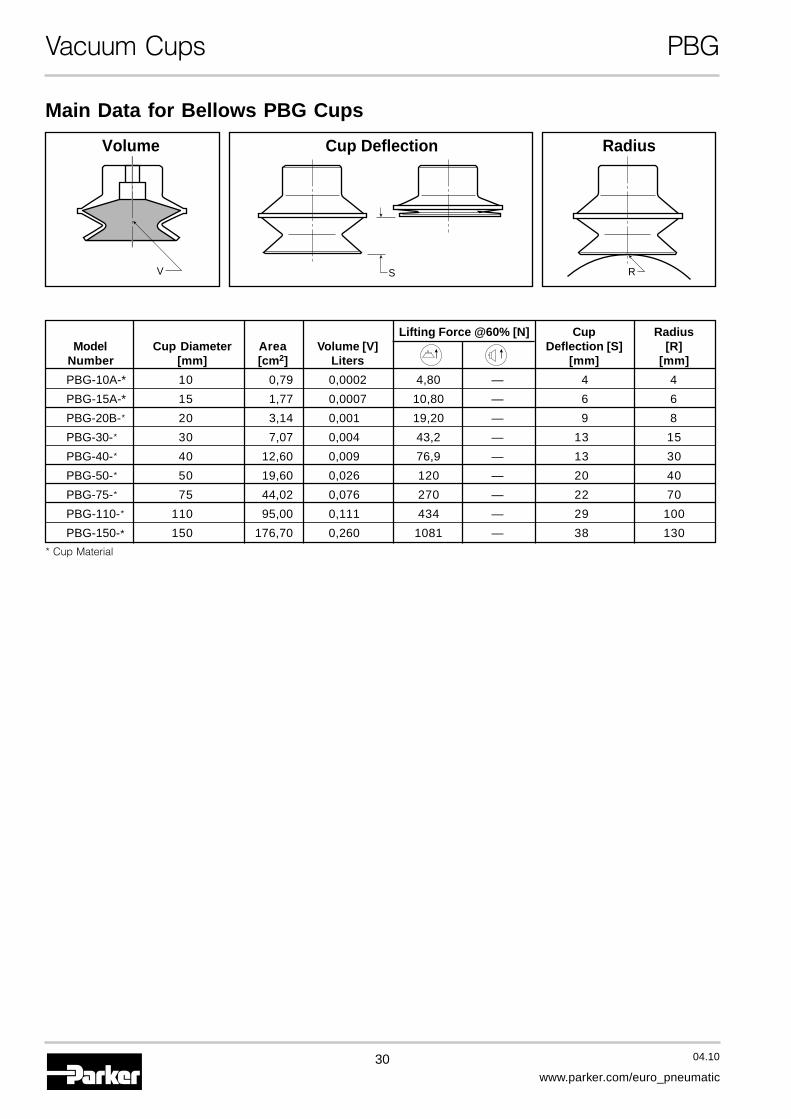
Main Data for Bellows PBG Cups
S RV
Volume RadiusCup Deflection
Lifting Force @60% [N] Cup RadiusModel Cup Diameter Area Volume [V] Deflection [S] [R]
Number [mm] [cm2] Liters [mm] [mm]
PBG-10A-* 10 0,79 0,0002 4,80 — 4 4
PBG-15A-* 15 1,77 0,0007 10,80 — 6 6
PBG-20B-* 20 3,14 0,001 19,20 — 9 8
PBG-30-* 30 7,07 0,004 43,2 — 13 15
PBG-40-* 40 12,60 0,009 76,9 — 13 30
PBG-50-* 50 19,60 0,026 120 — 20 40
PBG-75-* 75 44,02 0,076 270 — 22 70
PBG-110-* 110 95,00 0,111 434 — 29 100
PBG-150-* 150 176,70 0,260 1081 — 38 130
* Cup Material

31 04.10
www.parker.com/euro_pneumatic
A
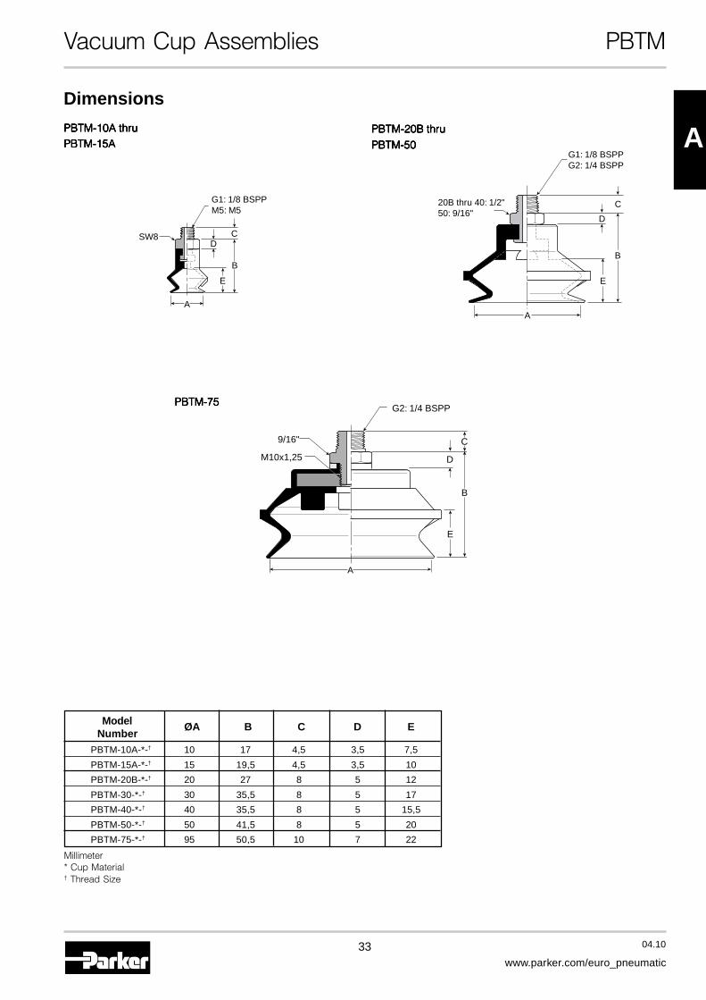
Model ØA ØB ØC ØD E F G H ØJNumber
PBG-10A-* 10,6 4 2 12,5 13,5 7,5 6 2 6
PBG-15A-* 15 4 4 17 16 10 6 2 6
PBG-20B-* 20 6 10,8 24 22 12 — 7 —
PBG-30-* 30 5,8 10,8 36 30,5 17 — 7 —
PBG-40-* 40 5,8 10,8 46 30,5 15,5 — 7 —
PBG-50-* 50 7,8 19,8 59,5 36,5 20 — 7 —
PBG-75-* 75 12,5 — 84 43,5 22 — 2,5 —
PBG-110-* 110 14 14 122 57,5 29 — 1,5
PBG-150-* 150 20 14 167 76,5 38 4xØ 9xØ 40 1,5 —
Millimeter* Cup Material
Vacuum Cups PBG
PBG-10A andPBG-10A andPBG-10A andPBG-10A andPBG-10A andPBG-15APBG-15APBG-15APBG-15APBG-15A
PBG-75PBG-75PBG-75PBG-75PBG-75
PBG-110 andPBG-110 andPBG-110 andPBG-110 andPBG-110 andPBG-150PBG-150PBG-150PBG-150PBG-150
PBG-20B thruPBG-20B thruPBG-20B thruPBG-20B thruPBG-20B thru
PBG-50PBG-50PBG-50PBG-50PBG-50
E
AC
JD
B
F
G
H
EF
AC
DB
H
E
A
D
B M10x1,25
F
H
A
D
C
BG
E
F
H
Dimensions
32 04.10
www.parker.com/euro_pneumatic
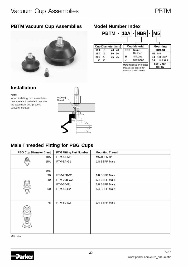
Vacuum Cup Assemblies PBTM
Male Threaded Fitting for PBG Cups
PBTM Vacuum Cup Assemblies
MountingThread
InstallationNote:Note:Note:Note:Note:When installing cup assemblies,use a sealant material to securethe assembly and preventvacuum leakage.
Millimeter
PBG Cup Diameter [mm] FTM Fitting Part Number Mounting Thread
10A FTM-5A-M5 M5x0,8 Male
15A FTM-5A-G1 1/8 BSPP Male
20B
30 FTM-20B-G1 1/8 BSPP Male
40 FTM-20B-G2 1/4 BSPP Male
FTM-50-G1 1/8 BSPP Male
50 FTM-50-G2 1/4 BSPP Male
75 FTM-60-G2 1/4 BSPP Male
Cup Diameter [mm]10A 10 40 4015A 15 50 5020B 20 75 75
30 30
Cup MaterialNBR Nitrile
RubberSI SiliconeU Urethane
Model Number IndexPBTM - 10A - NBR - M5
MountingThread
M5 M5G1 1/8 BSPPG2 1/4 BSPP
See ChartBelow
More materials on request.Please see page 8 formaterial specifications.
33 04.10
www.parker.com/euro_pneumatic
APBTM-10A thruPBTM-10A thruPBTM-10A thruPBTM-10A thruPBTM-10A thruPBTM-15APBTM-15APBTM-15APBTM-15APBTM-15A
PBTM-20B thruPBTM-20B thruPBTM-20B thruPBTM-20B thruPBTM-20B thru
PBTM-50PBTM-50PBTM-50PBTM-50PBTM-50
PBTM-75PBTM-75PBTM-75PBTM-75PBTM-75
G1: 1/8 BSPPG2: 1/4 BSPP
20B thru 40: 1/2"50: 9/16"
A
E
B
C
D
B
C
D
E
G2: 1/4 BSPP
9/16"
M10x1,25
A
Model ØA B C D ENumber
PBTM-10A-*-† 10 17 4,5 3,5 7,5
PBTM-15A-*-† 15 19,5 4,5 3,5 10
PBTM-20B-*-† 20 27 8 5 12
PBTM-30-*-† 30 35,5 8 5 17
PBTM-40-*-† 40 35,5 8 5 15,5
PBTM-50-*-† 50 41,5 8 5 20
PBTM-75-*-† 95 50,5 10 7 22
Millimeter* Cup Material† Thread Size
Vacuum Cup Assemblies PBTM
A
SW8
G1: 1/8 BSPPM5: M5
E
B
CD
Dimensions

34 04.10
www.parker.com/euro_pneumatic
Vacuum Cup Assemblies PBTF
Female Threaded Fitting for PBG Cups
PBTF Vacuum Cup Assemblies
MountingThread
MountingThread
Installation
Note:Note:Note:Note:Note:When installing cup assemblies, use a sealant material to secure theassembly and prevent vacuum leakage.
Millimeter
PBG Cup Diameter [mm] FTF Fitting Part Number Mounting Thread
10A FTF-5A-M5 M5x0,8 Female15A FTF-5A-G1 1/8 BSPP Female
20B30 FTF-20B-G1 1/8 BSPP Female40 FTF-20B-G2 1/4 BSPP Female
50 FTF-50-G1 1/8 BSPP FemaleFTF-50-G2 1/4 BSPP Female
75 FTF-60-G2 1/4 BSPP Female
110150 FTF-120-G4 1/2 BSPP Female
Cup Diameter [mm]10A 10 50 5015A 15 75 7520B 20 110 110
30 30 150 15040 40
Cup MaterialNBR Nitrile
RubberSI SiliconeU Urethane
Model Number IndexPBTF - 10A - NBR - M5
MountingThread
M5 M5G1 1/8 BSPPG2 1/4 BSPPG4 1/2 BSPP
See ChartBelow
More materials on request.Please see page 8 formaterial specifications.

35 04.10
www.parker.com/euro_pneumatic
A
Vacuum Cup Assemblies PBTF
PBTF-10A thruPBTF-10A thruPBTF-10A thruPBTF-10A thruPBTF-10A thruPBTF-15APBTF-15APBTF-15APBTF-15APBTF-15A
PBTF-20B thruPBTF-20B thruPBTF-20B thruPBTF-20B thruPBTF-20B thruPBTF 50PBTF 50PBTF 50PBTF 50PBTF 50
PBTF-110 thruPBTF-110 thruPBTF-110 thruPBTF-110 thruPBTF-110 thruPBTF-150PBTF-150PBTF-150PBTF-150PBTF-150
G1: 1/8 BSPPG2: 1/4 BSPP
20B thru 40: 1/2"50: 9/16
A
E
C
B
A
G4: 1/2 BSPP
1/8 BSPP
B
D
E
C
57 O.D.
48 Across Flats
Dimensions
PBTF-75PBTF-75PBTF-75PBTF-75PBTF-75
B
E
C
G2: 1/4 BSPP
9/16"
A
A
G1: 1/8 BSPPM5x0,8
B
E
C
Model ØA B C D ENumber
PBTF-10A-*-† 10 21,5 8 — 7,5
PBTF-15A-*-† 15 24 8 — 10
PBTF-20B-*-† 20 36 14 — 12
PBTF-30-*-† 30 44,5 14 — 17
PBTF-40-*-† 40 44,5 14 — 15,5
PBTF-50-*-† 50 50,5 14 — 20
PBTF-75-*-† 95 60,5 19,5 — 22
PBTF-110-*-† 120 78 24 13 29
PBTF-150-*-† 150 97 24 13 38
Millimeter* Cup Material† Thread Size

36 04.10
www.parker.com/euro_pneumatic
Vacuum Cup Assemblies PBTK
PBTK Vacuum Cup Assemblies
InstallationMountingThread.
CupScrew
Barbed Bulkhead for PBG Cups
Note:Note:Note:Note:Note:When installing cup assemblies,use a sealant material to securethe assembly and preventvacuum leakage.
Millimeter
PBG Cup Diameter [mm] FTK Part Number Mounting Thread
10AFTK-5A M9x1,0 Male
15A
20B30 FTK-20B M10x1,25 Male4050 FTK-50 M10x1,25 Male
75 FTK-60-G1 M16x1,5 Male
Model Number IndexPBTK - 10A - NBR - —
Vacuum PortBlank Barb
G1 1/8 BSPPSee Chart
Below
Cup Diameter [mm]10A 10 40 4015A 15 50 5020B 20 75 75
30 30
Cup MaterialNBR Nitrile
RubberSI SiliconeU Urethane
More materials on request.Please see page 8 formaterial specifications.
37 04.10
www.parker.com/euro_pneumatic
A
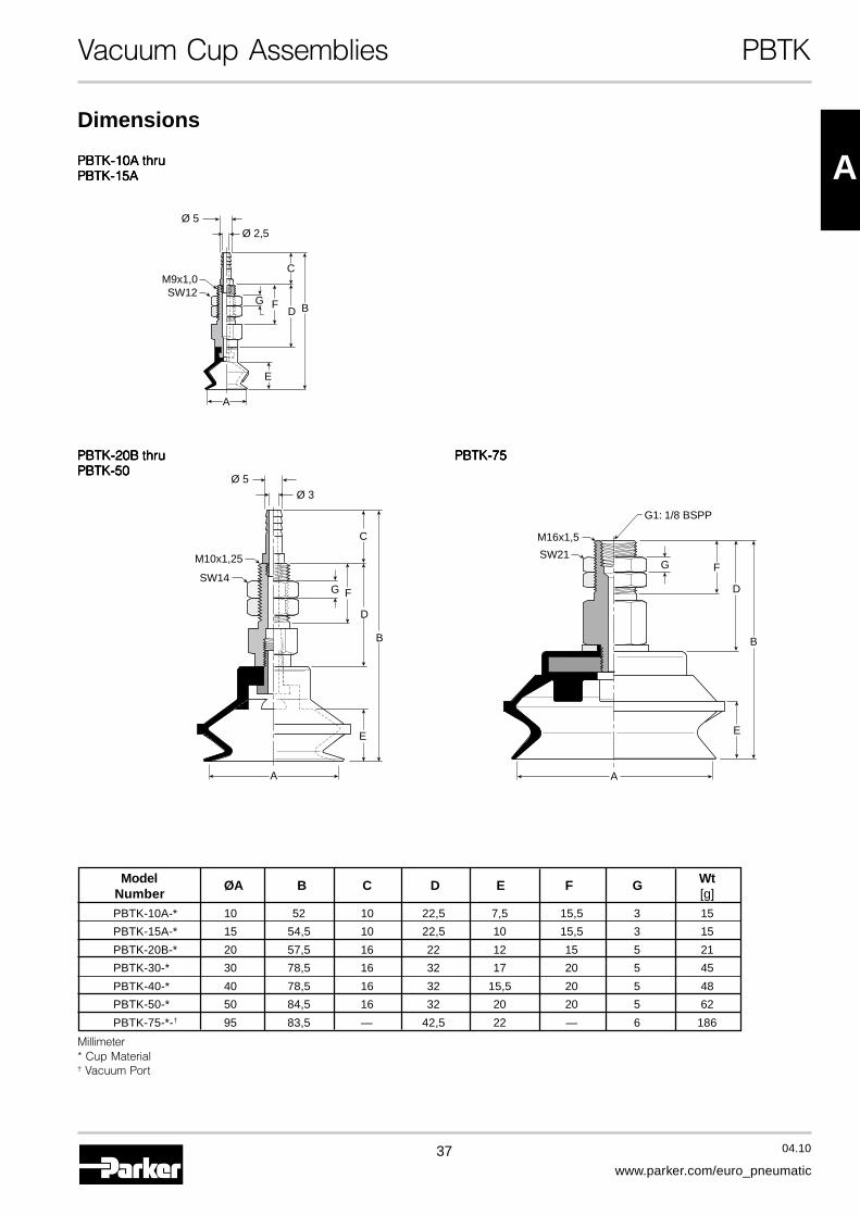
Vacuum Cup Assemblies PBTK
PBTK-10A thruPBTK-10A thruPBTK-10A thruPBTK-10A thruPBTK-10A thruPPPPPBTK-15ABTK-15ABTK-15ABTK-15ABTK-15A
E
A
Ø 5Ø 2,5
FG
C
D B
M9x1,0SW12
PBTK-75PBTK-75PBTK-75PBTK-75PBTK-75
A
G1: 1/8 BSPP
SW21
M16x1,5
B
FG
D
E
Dimensions
PBTK-20B thruPBTK-20B thruPBTK-20B thruPBTK-20B thruPBTK-20B thruPBTK-50PBTK-50PBTK-50PBTK-50PBTK-50
A
B
FG
C
D
E
M10x1,25
SW14
Ø 5Ø 3
Model ØA B C D E F G WtNumber [g]
PBTK-10A-* 10 52 10 22,5 7,5 15,5 3 15
PBTK-15A-* 15 54,5 10 22,5 10 15,5 3 15
PBTK-20B-* 20 57,5 16 22 12 15 5 21
PBTK-30-* 30 78,5 16 32 17 20 5 45
PBTK-40-* 40 78,5 16 32 15,5 20 5 48
PBTK-50-* 50 84,5 16 32 20 20 5 62
PBTK-75-*-† 95 83,5 — 42,5 22 — 6 186
Millimeter* Cup Material† Vacuum Port

38 04.10
www.parker.com/euro_pneumatic
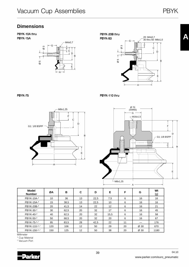
Vacuum Cup Assemblies PBYK
Model Number Index
90° Barbed Adapter for PBG Cups
PBYK Vacuum Cup AssembliesPBYK - 10A - NBR - —
MountingThread.
Cup Screw
InstallationNote:Note:Note:Note:Note:When installing cup assemblies,use a sealant material to securethe assembly and preventvacuum leakage.
Millimeter
Vacuum PortBlank Barb
G1 1/8 BSPPSee Chart
Below
Cup Diameter [mm]10A 10 40 4015A 15 50 5020B 20 75 75
30 30 150 15040 40
Cup MaterialNBR Nitrile
RubberSI SiliconeU Urethane
PBG Cup Diameter [mm] FYK Part Number Mounting Thread
10AFYK-5A M4x0,7 Female
15A
20B30 FYK-20B M6x1,0 Female40
50 FYK-50 M6x1,0 Female
75 FYK-60-G1 M8x1,25 Female
110
150 FYK-120-G1 M16x1,5 Female
More materials on request.Please see page 8 formaterial specifications.
39 04.10
www.parker.com/euro_pneumatic
A
Vacuum Cup Assemblies PBYK
Dimensions
Model ØA B C D E F G WtNumber [g]
PBYK-10A-* 10 36 13 22,5 7,5 6 16 16
PBYK-15A-* 15 38,5 13 22,5 10 6 16 16
PBYK-20B-* 20 41,5 14 22 12 6 16 21
PBYK-30-* 30 62,5 20 32 17 6 16 45
PBYK-40-* 40 62,5 20 32 15,5 6 16 58
PBYK-50-* 50 68,5 20 32 20 6 16 67
PBYK-75-*-† 95 83,5 28 42,5 22 11 — 176
PBYK-110-*-† 120 106 12 50 29 20 Ø 30 670
PBYK-150-*-† 150 125 12 50 38 20 Ø 30 1180
Millimeter* Cup Material† Vacuum Port
PBYK-20B thruPBYK-20B thruPBYK-20B thruPBYK-20B thruPBYK-20B thruPBYK-50PBYK-50PBYK-50PBYK-50PBYK-50
B
F
G
20: M4x0,730 thru 50: M6x1,0
C
D
E
Ø 5
Ø 3
A
PBYK-10A thruPBYK-10A thruPBYK-10A thruPBYK-10A thruPBYK-10A thru
PBYK-15APBYK-15APBYK-15APBYK-15APBYK-15A
FC
DB
E
Ø 5
Ø 3
M4x0,7G
A
PBYK-75PBYK-75PBYK-75PBYK-75PBYK-75
M8x1,25
B
F
G1: 1/8 BSPP
C
D
E
A
A
Ø 70(SW65)
G
M16x1,5
G1: 1/8 BSPP
M8x1,25
BC
D
E
F
PBYK-110 thruPBYK-110 thruPBYK-110 thruPBYK-110 thruPBYK-110 thru
40 04.10
www.parker.com/euro_pneumatic
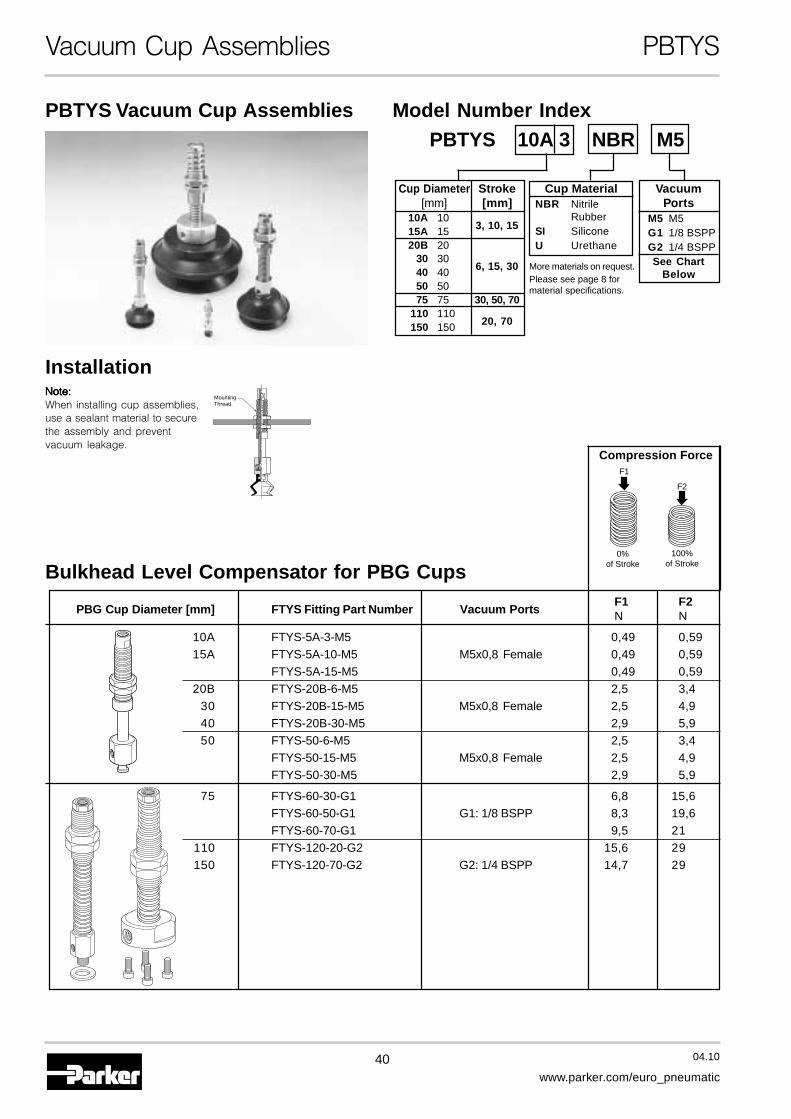
Vacuum Cup Assemblies PBTYS
Bulkhead Level Compensator for PBG Cups
PBTYS Vacuum Cup Assemblies
MountingThread.
Installation
Compression ForceF1
0%of Stroke
100%of Stroke
F2
Note:Note:Note:Note:Note:When installing cup assemblies,use a sealant material to securethe assembly and preventvacuum leakage.
PBG Cup Diameter [mm] FTYS Fitting Part Number Vacuum PortsF1 F2N N
10A FTYS-5A-3-M5 0,49 0,5915A FTYS-5A-10-M5 M5x0,8 Female 0,49 0,59
FTYS-5A-15-M5 0,49 0,5920B FTYS-20B-6-M5 2,5 3,4
30 FTYS-20B-15-M5 M5x0,8 Female 2,5 4,940 FTYS-20B-30-M5 2,9 5,950 FTYS-50-6-M5 2,5 3,4
FTYS-50-15-M5 M5x0,8 Female 2,5 4,9FTYS-50-30-M5 2,9 5,9
75 FTYS-60-30-G1 6,8 15,6FTYS-60-50-G1 G1: 1/8 BSPP 8,3 19,6FTYS-60-70-G1 9,5 21
110 FTYS-120-20-G2 15,6 29150 FTYS-120-70-G2 G2: 1/4 BSPP 14,7 29
Model Number Index
Cup MaterialNBR Nitrile
RubberSI SiliconeU Urethane
PBTYS 10A 3 NBR M5
VacuumPorts
M5 M5G1 1/8 BSPPG2 1/4 BSPPSee Chart
Below
Cup Diameter Stroke[mm] [mm]
10A 103, 10, 1515A 15
20B 2030 30
6, 15, 3040 4050 5075 75 30, 50, 70
110 11020, 70150 150
More materials on request.Please see page 8 formaterial specifications.
41 04.10
www.parker.com/euro_pneumatic
A
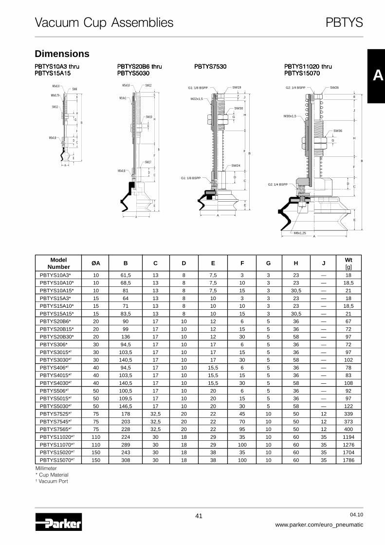
Vacuum Cup Assemblies PBTYS
Model ØA B C D E F G H J WtNumber [g]
PBTYS10A3* 10 61,5 13 8 7,5 3 3 23 — 18
PBTYS10A10* 10 68,5 13 8 7,5 10 3 23 — 18,5
PBTYS10A15* 10 81 13 8 7,5 15 3 30,5 — 21
PBTYS15A3* 15 64 13 8 10 3 3 23 — 18
PBTYS15A10* 15 71 13 8 10 10 3 23 — 18,5
PBTYS15A15* 15 83,5 13 8 10 15 3 30,5 — 21
PBTYS20B6* 20 90 17 10 12 6 5 36 — 67
PBTYS20B15* 20 99 17 10 12 15 5 36 — 72
PBTYS20B30* 20 136 17 10 12 30 5 58 — 97
PBTYS306* 30 94,5 17 10 17 6 5 36 — 72
PBTYS3015*† 30 103,5 17 10 17 15 5 36 — 97
PBTYS3030*† 30 140,5 17 10 17 30 5 58 — 102
PBTYS406*† 40 94,5 17 10 15,5 6 5 36 — 78
PBTYS4015*† 40 103,5 17 10 15,5 15 5 36 — 83
PBTYS4030*† 40 140,5 17 10 15,5 30 5 58 — 108
PBTYS506*† 50 100,5 17 10 20 6 5 36 — 92
PBTYS5015*† 50 109,5 17 10 20 15 5 36 — 97
PBTYS5030*† 50 146,5 17 10 20 30 5 58 — 122
PBTYS7525*† 75 178 32,5 20 22 45 10 50 12 339
PBTYS7545*† 75 203 32,5 20 22 70 10 50 12 373
PBTYS7565*† 75 228 32,5 20 22 95 10 50 12 400
PBTYS11020*† 110 224 30 18 29 35 10 60 35 1194
PBTYS11070*† 110 289 30 18 29 100 10 60 35 1276
PBTYS15020*† 150 243 30 18 38 35 10 60 35 1704
PBTYS15070*† 150 308 30 18 38 100 10 60 35 1786
Millimeter* Cup Material† Vacuum Port
PBTYS20B6 thruPBTYS20B6 thruPBTYS20B6 thruPBTYS20B6 thruPBTYS20B6 thruPBTYS5030PBTYS5030PBTYS5030PBTYS5030PBTYS5030
PBTYS10A3 thruPBTYS10A3 thruPBTYS10A3 thruPBTYS10A3 thruPBTYS10A3 thruPBTYS15A15PBTYS15A15PBTYS15A15PBTYS15A15PBTYS15A15
PBTYS7530PBTYS7530PBTYS7530PBTYS7530PBTYS7530 PBTYS11020 thruPBTYS11020 thruPBTYS11020 thruPBTYS11020 thruPBTYS11020 thruPBTYS15070PBTYS15070PBTYS15070PBTYS15070PBTYS15070
Dimensions
M5x0,8
M5x0,8
SW6
SW12
M8x0,75
B
D C
F
9
H
G
E
A
M5x0,8
M5x0,8
SW12
SW19
SW17
M14x1
B
D
E
C
H
5
F
G
A
G1: 1/8 BSPP
G1: 1/8 BSPP
SW19
SW30
SW24
M22x1,5
B
D
A
E
C
H
J7
F
G
AM8x1,25
SW26
SW36
M30x1,5
B
D
E
C
J
8
F
HG
G2: 1/4 BSPP
G2: 1/4 BSPP
42 04.10
www.parker.com/euro_pneumatic
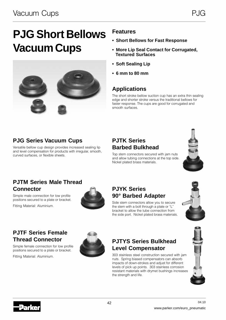
Vacuum Cups PJG
PJG Short BellowsVacuum Cups
Features
• Short Bellows for Fast Response
• More Lip Seal Contact for Corrugated,Textured Surfaces
• Soft Sealing Lip
• 6 mm to 80 mm
ApplicationsThe short stroke bellow suction cup has an extra thin sealingedge and shorter stroke versus the traditional bellows forfaster response. The cups are good for corrugated andsmooth surfaces.
PJG Series Vacuum CupsVersatile bellow cup design provides increased sealing lipand level compensation for products with irregular, smooth,curved surfaces, or flexible sheets.
PJTM Series Male ThreadConnectorSimple male connection for low profilepositions secured to a plate or bracket.
Fitting Material: Aluminium.
PJTF Series FemaleThread ConnectorSimple female connection for low profilepositions secured to a plate or bracket.
Fitting Material: Aluminium.
PJTK SeriesBarbed BulkheadTop stem connectors secured with jam nutsand allow tubing connections at the top side.Nickel plated brass materials.
PJYK Series90° Barbed AdapterSide stem connectors allow you to securethe stem with a bolt through a plate or “L”bracket to allow the tube connection fromthe side port. Nickel plated brass materials.
PJTYS Series BulkheadLevel Compensator303 stainless steel construction secured with jamnuts. Spring biased compensators can absorbimpacts of down-strokes and adjust for differentlevels of pick up points. 303 stainless corrosionresistant materials with drymet bushings increasesthe strength and life.
43 04.10
www.parker.com/euro_pneumatic
A
Vacuum Cups PJG
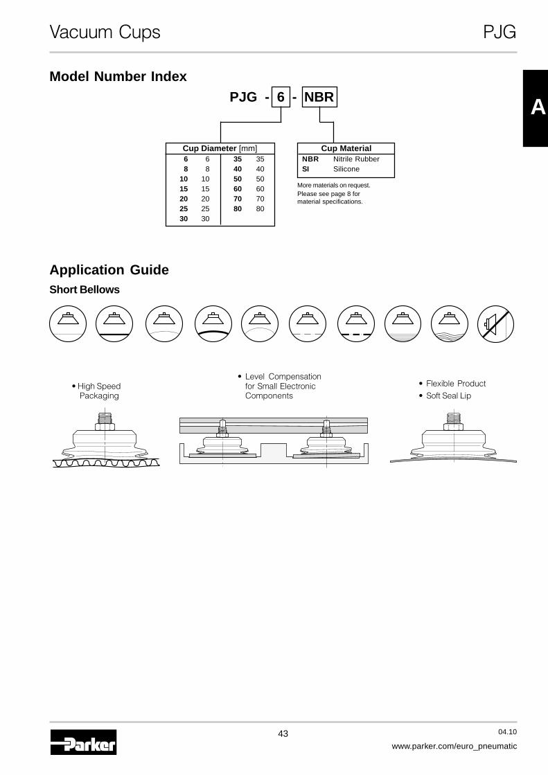
PJG - 6 - NBR
Cup Diameter [mm]6 6 35 358 8 40 40
10 10 50 5015 15 60 6020 20 70 7025 25 80 8030 30
Model Number Index
Cup MaterialNBR Nitrile RubberSI Silicone
Application GuideShort Bellows
• High SpeedPackaging
• Level Compensationfor Small ElectronicComponents
• Flexible Product• Soft Seal Lip
More materials on request.Please see page 8 formaterial specifications.

44 04.10
www.parker.com/euro_pneumatic
Vacuum Cups PJG
Main Data for Short Bellows PJG Cups
S RV
Volume RadiusCup Deflection
Lifting Force @ 60% [N] Cup RadiusModel Cup Diameter Area Volume [V] Deflection (S) R
Number [mm] [cm2] Liters [mm] [mm]
PJG-6-* 6 0,28 0,000016 1,70 — 4,2 4,0
PJG-8-* 8 0,50 0,00007 3,10 — 4,0 5,0
PJG-10-* 10 0,79 0,00017 4,80 — 3,0 6,0
PJG-15-* 15 1,77 0,0005 10,8 — 3,3 10,0
PJG-20-* 20 3,14 0,0012 19,2 — 5,5 13,0
PJG-25-* 25 4,91 0,0025 30,0 — 6,5 17,5
PJG-30-* 30 7,07 0,003 43,2 — 7,0 26,0
PJG-35-* 35 9,62 0,004 58,9 — 7,0 31,0
PJG-40-* 40 12,6 0,005 76,9 — 7,2 37,0
PJG-50-* 50 19,6 0,008 120 — 9,0 41,0
PJG-60-* 60 28,3 0,020 173 — 8,0 70,0
PJG-70-* 70 38,5 0,030 235 — 9,5 90,0
PJG-80-* 80 50,3 0,040 308 — 9,5 100,0
*Cup Material

45 04.10
www.parker.com/euro_pneumatic
A
Vacuum Cups PJG
PJG-6 thruPJG-6 thruPJG-6 thruPJG-6 thruPJG-6 thruPJG-8PJG-8PJG-8PJG-8PJG-8
PJG-50PJG-50PJG-50PJG-50PJG-50 PJG-60 thruPJG-60 thruPJG-60 thruPJG-60 thruPJG-60 thru
PJG-80PJG-80PJG-80PJG-80PJG-80
PJG-10 andPJG-10 andPJG-10 andPJG-10 andPJG-10 andPJG-15PJG-15PJG-15PJG-15PJG-15
A
D
F
E
HBM10x1,25
H
A
D
F
E
E
PJG-30 thruPJG-30 thruPJG-30 thruPJG-30 thruPJG-30 thru
PJG-40PJG-40PJG-40PJG-40PJG-40PJG-20PJG-20PJG-20PJG-20PJG-20
EF
AC
DB
H E
F
AC
DB
H
E
FAC
DB
HE
F
AC
DB
H
Dimensions
Model ØA ØB ØC ØD E F HNumberPJG-6-* 6 4 6 7,5 9 4,2 2
PJG-8-* 8 4 6 8 9 4 2
PJG-10-* 10 4,6 7,8 11 9,5 3 3,5
PJG-15-* 15 4,6 7,8 12 11 3,3 3,5
PJG-20-* 20 4,6 10,8 15 13 5,5 4,5
PJG-25-* 25 4,6 10,8 17,5 15,5 6,5 4,5
PJG-30-* 30 5,8 10,8 20 18 7 7
PJG-35-* 35 5,8 10,8 25 18 7 7
PJG-40-* 40 5,8 10,8 30 18 7,2 7
PJG-50-* 50 7,8 19,8 40 20 9 7
PJG-60-* 60 12,5 — 45 22,5 8 2,5
PJG-70-* 70 12,5 — 55 23,5 9,5 2,5
PJG-80-* 80 12,5 — 68 23,5 9,5 2,5
Millimeter* Cup Material
46 04.10
www.parker.com/euro_pneumatic
Vacuum Cup Assemblies PJTM
Male Threaded Fitting for PJG Cups
PJTM Vacuum Cup Assemblies
MountingThread
InstallationNote:Note:Note:Note:Note:When installing cup assemblies,use a sealant material to securethe assembly and preventvacuum leakage.
Millimeter
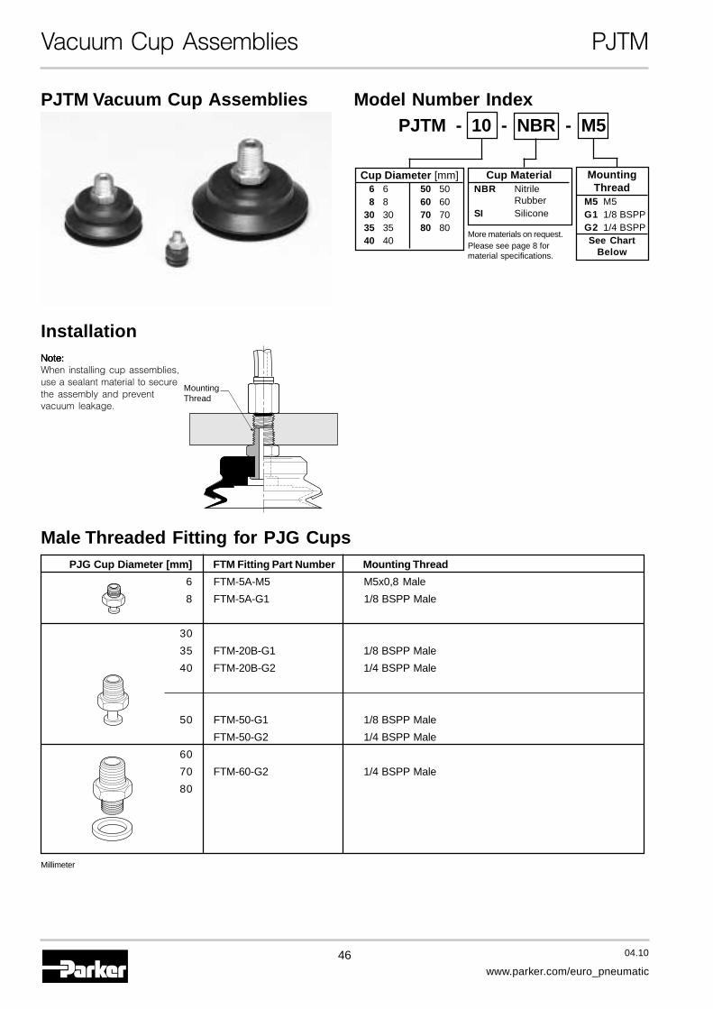
PJG Cup Diameter [mm] FTM Fitting Part Number Mounting Thread
6 FTM-5A-M5 M5x0,8 Male
8 FTM-5A-G1 1/8 BSPP Male
30
35 FTM-20B-G1 1/8 BSPP Male
40 FTM-20B-G2 1/4 BSPP Male
50 FTM-50-G1 1/8 BSPP Male
FTM-50-G2 1/4 BSPP Male
60
70 FTM-60-G2 1/4 BSPP Male
80
Cup Diameter [mm]6 6 50 508 8 60 60
30 30 70 7035 35 80 8040 40
Cup MaterialNBR Nitrile
RubberSI Silicone
Model Number IndexPJTM - 10 - NBR - M5
MountingThread
M5 M5G1 1/8 BSPPG2 1/4 BSPPSee Chart
Below
More materials on request.Please see page 8 formaterial specifications.
47 04.10
www.parker.com/euro_pneumatic
A
Vacuum Cup Assemblies PJTM
Dimensions
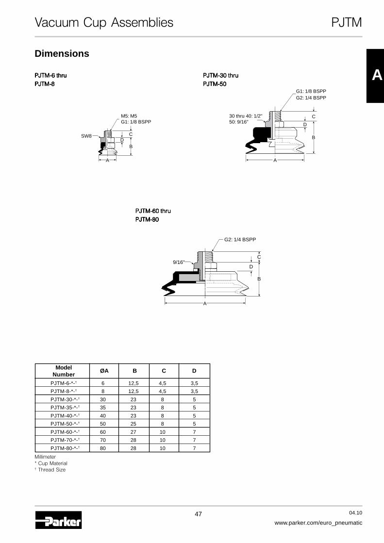
PJTM-60 thruPJTM-60 thruPJTM-60 thruPJTM-60 thruPJTM-60 thruPJTM-80PJTM-80PJTM-80PJTM-80PJTM-80
B
C
D
G2: 1/4 BSPP
9/16"
A
PJTM-30 thruPJTM-30 thruPJTM-30 thruPJTM-30 thruPJTM-30 thruPJTM-50PJTM-50PJTM-50PJTM-50PJTM-50
G1: 1/8 BSPPG2: 1/4 BSPP
30 thru 40: 1/2"50: 9/16"
A
B
C
D
PJTM-6 thruPJTM-6 thruPJTM-6 thruPJTM-6 thruPJTM-6 thruPJTM-8PJTM-8PJTM-8PJTM-8PJTM-8
A
SW8
M5: M5G1: 1/8 BSPP
B
CD
Model ØA B C DNumber
PJTM-6-*-† 6 12,5 4,5 3,5
PJTM-8-*-† 8 12,5 4,5 3,5
PJTM-30-*-† 30 23 8 5
PJTM-35-*-† 35 23 8 5
PJTM-40-*-† 40 23 8 5
PJTM-50-*-† 50 25 8 5
PJTM-60-*-† 60 27 10 7
PJTM-70-*-† 70 28 10 7
PJTM-80-*-† 80 28 10 7
Millimeter* Cup Material† Thread Size

48 04.10
www.parker.com/euro_pneumatic
Vacuum Cup Assemblies PJTF
Female Threaded Fitting for PJG Cups
PJTF Vacuum Cup Assemblies
MountingThread
MountingThread
Installation
Note:Note:Note:Note:Note:When installing cup assemblies, use a sealant material to secure theassembly and prevent vacuum leakage.
Millimeter
Cup Diameter [mm]6 6 50 508 8 60 60
30 30 70 7035 35 80 8040 40
Cup MaterialNBR Nitrile
RubberSI Silicone
Model Number IndexPJTF - 10 - NBR - M5
MountingThread
M5 M5G1 1/8 BSPPG2 1/4 BSPPSee Chart
Below
PJG Cup Diameter [mm] FTF Fitting Part Number Mounting Thread
6 FTF-5A-M5 M5x0,8 Female
8 FTF-5A-G1 1/8 BSPP Female
30
35 FTF-20B-G1 G1/8 Female
40
50 FTF-50-G1 G1/8 Female
FTF-50-G2 G1/4 Female
60
70 FTF-60-G2 G1/4 Female
80
More materials on request.Please see page 8 formaterial specifications.
49 04.10
www.parker.com/euro_pneumatic
A
Vacuum Cup Assemblies PJTF
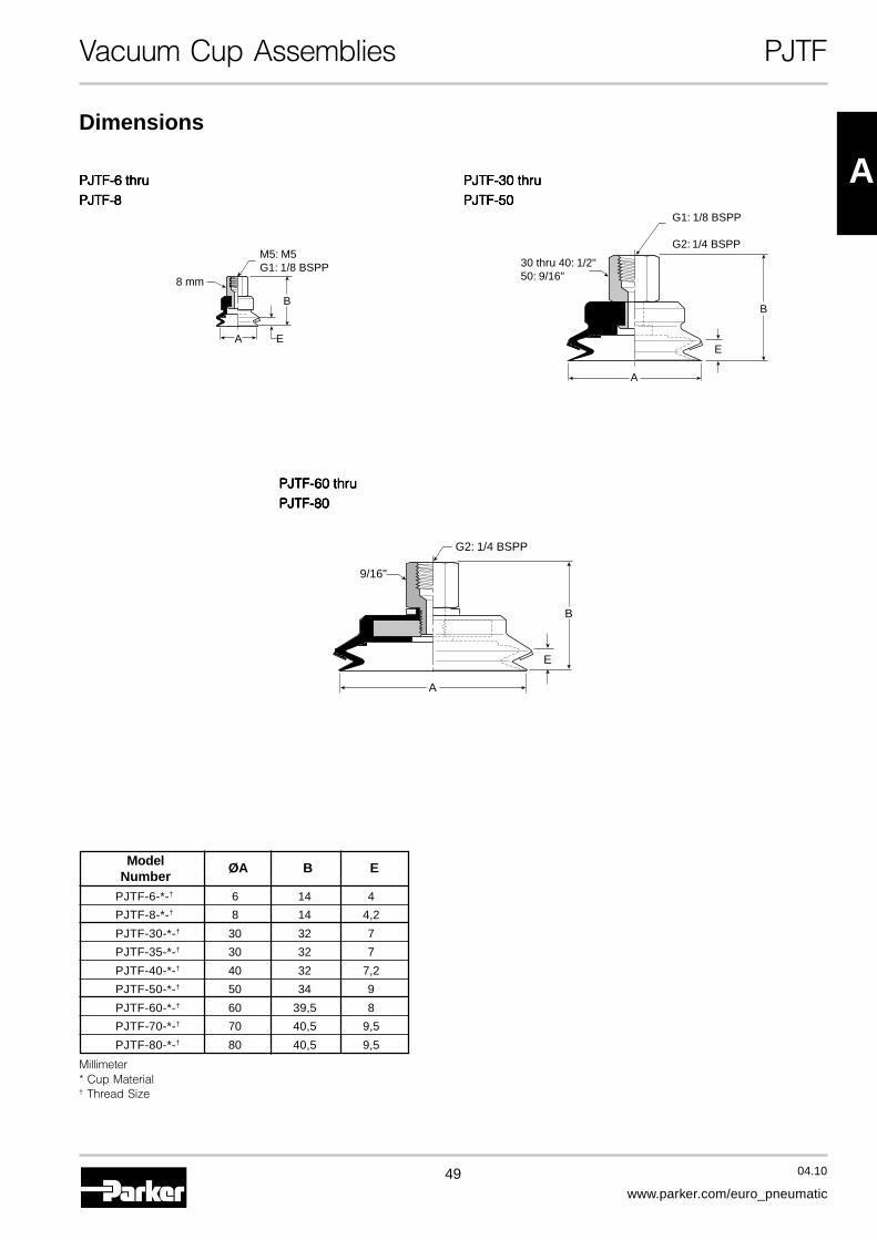
PJTF-6 thruPJTF-6 thruPJTF-6 thruPJTF-6 thruPJTF-6 thru
PJTF-8PJTF-8PJTF-8PJTF-8PJTF-8
PJTF-60 thruPJTF-60 thruPJTF-60 thruPJTF-60 thruPJTF-60 thru
PJTF-80PJTF-80PJTF-80PJTF-80PJTF-80
PJTF-30 thruPJTF-30 thruPJTF-30 thruPJTF-30 thruPJTF-30 thru
PJTF-50PJTF-50PJTF-50PJTF-50PJTF-50
M5: M5G1: 1/8 BSPP
B
8 mm
EA
A
B
E
G2: 1/4 BSPP
9/16"
G1: 1/8 BSPP
G2: 1/4 BSPP
30 thru 40: 1/2"50: 9/16"
E
B
A
Dimensions
Model ØA B ENumber
PJTF-6-*-† 6 14 4
PJTF-8-*-† 8 14 4,2
PJTF-30-*-† 30 32 7
PJTF-35-*-† 30 32 7
PJTF-40-*-† 40 32 7,2
PJTF-50-*-† 50 34 9
PJTF-60-*-† 60 39,5 8
PJTF-70-*-† 70 40,5 9,5
PJTF-80-*-† 80 40,5 9,5
Millimeter* Cup Material† Thread Size
50 04.10
www.parker.com/euro_pneumatic
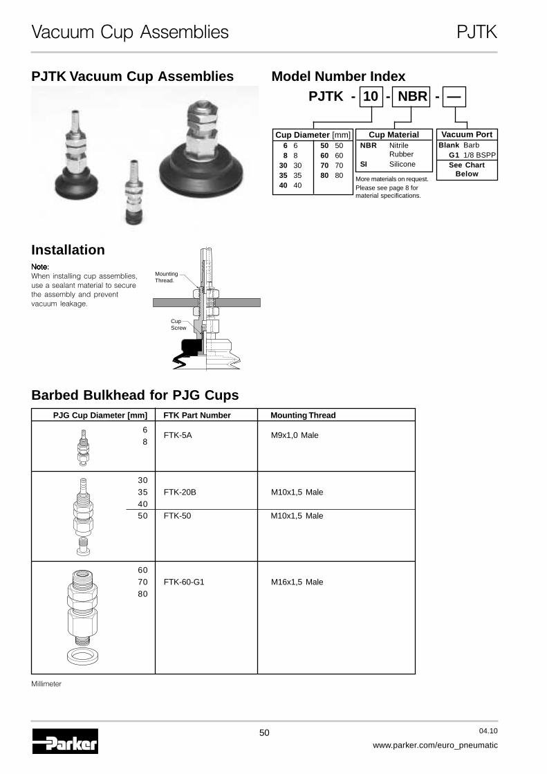
Vacuum Cup Assemblies PJTK
PJTK Vacuum Cup Assemblies
Installation
MountingThread.
CupScrew
Barbed Bulkhead for PJG Cups
Note:Note:Note:Note:Note:When installing cup assemblies,use a sealant material to securethe assembly and preventvacuum leakage.
Millimeter
Cup Diameter [mm]6 6 50 508 8 60 60
30 30 70 7035 35 80 8040 40
Cup MaterialNBR Nitrile
RubberSI Silicone
Model Number IndexPJTK - 10 - NBR - —
Vacuum PortBlank Barb
G1 1/8 BSPPSee Chart
Below
PJG Cup Diameter [mm] FTK Part Number Mounting Thread
6FTK-5A M9x1,0 Male
8
3035 FTK-20B M10x1,5 Male4050 FTK-50 M10x1,5 Male
6070 FTK-60-G1 M16x1,5 Male80
More materials on request.Please see page 8 formaterial specifications.
51 04.10
www.parker.com/euro_pneumatic
A
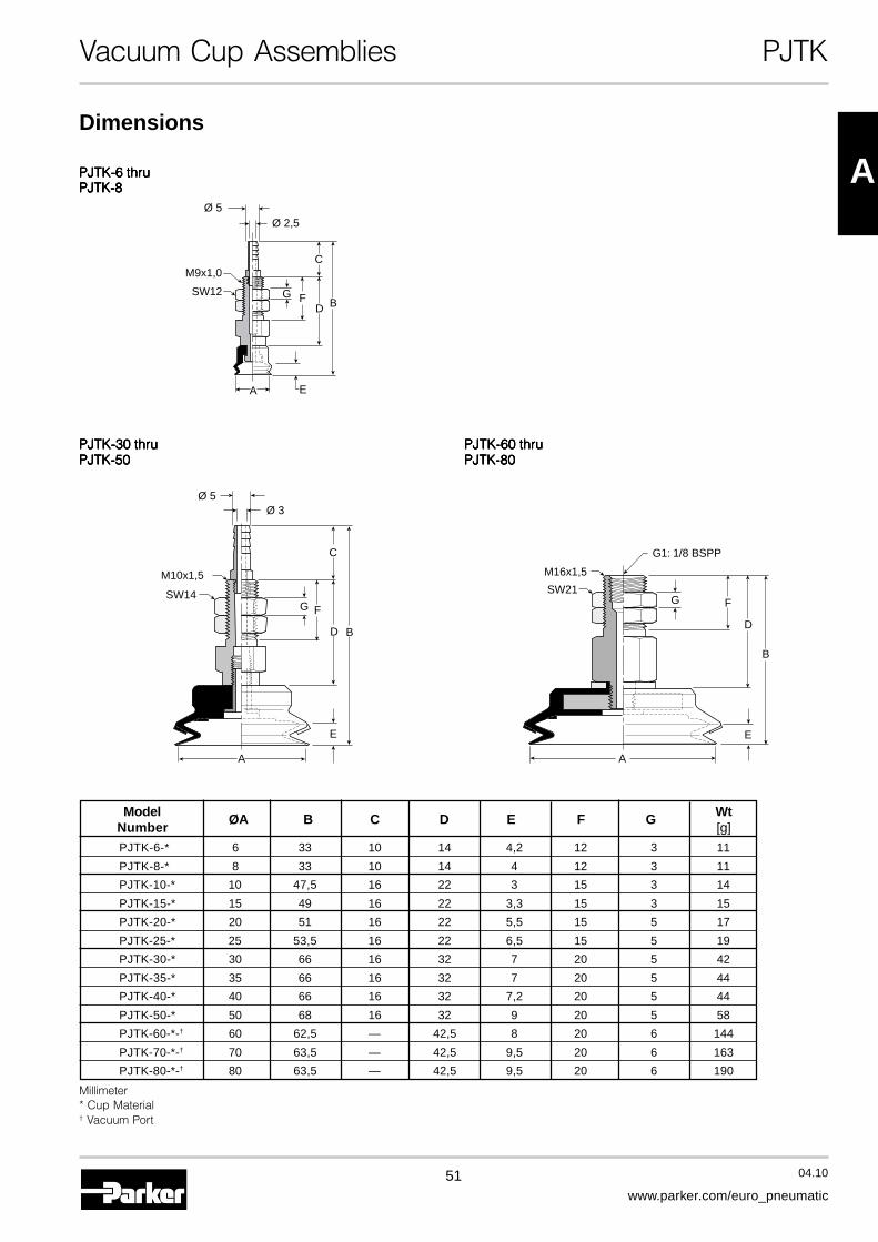
Vacuum Cup Assemblies PJTK
Dimensions
Model ØA B C D E F G WtNumber [g]
PJTK-6-* 6 33 10 14 4,2 12 3 11
PJTK-8-* 8 33 10 14 4 12 3 11
PJTK-10-* 10 47,5 16 22 3 15 3 14
PJTK-15-* 15 49 16 22 3,3 15 3 15
PJTK-20-* 20 51 16 22 5,5 15 5 17
PJTK-25-* 25 53,5 16 22 6,5 15 5 19
PJTK-30-* 30 66 16 32 7 20 5 42
PJTK-35-* 35 66 16 32 7 20 5 44
PJTK-40-* 40 66 16 32 7,2 20 5 44
PJTK-50-* 50 68 16 32 9 20 5 58
PJTK-60-*-† 60 62,5 — 42,5 8 20 6 144
PJTK-70-*-† 70 63,5 — 42,5 9,5 20 6 163
PJTK-80-*-† 80 63,5 — 42,5 9,5 20 6 190
Millimeter* Cup Material† Vacuum Port
PJTK-60 thruPJTK-60 thruPJTK-60 thruPJTK-60 thruPJTK-60 thruPJTK-80PJTK-80PJTK-80PJTK-80PJTK-80
G1: 1/8 BSPP
SW21
M16x1,5
B
FG
D
E
A
PJTK-30 thruPJTK-30 thruPJTK-30 thruPJTK-30 thruPJTK-30 thruPJTK-50PJTK-50PJTK-50PJTK-50PJTK-50
A
B
FG
C
D
E
M10x1,5
SW14
Ø 5Ø 3
PJTK-6 thruPJTK-6 thruPJTK-6 thruPJTK-6 thruPJTK-6 thruPJTK-8PJTK-8PJTK-8PJTK-8PJTK-8
EA
Ø 5Ø 2,5
FG
C
D B
M9x1,0
SW12
52 04.10
www.parker.com/euro_pneumatic
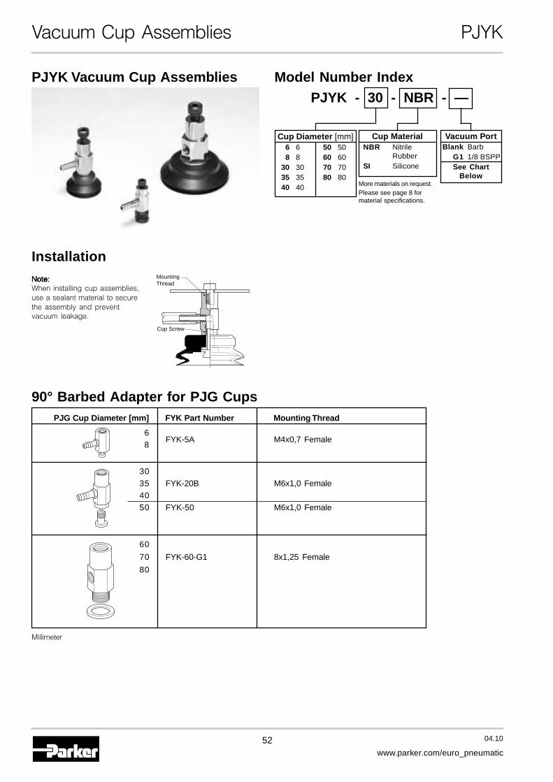
Vacuum Cup Assemblies PJYK
90° Barbed Adapter for PJG Cups
PJYK Vacuum Cup Assemblies
MountingThread
Cup Screw
InstallationNote:Note:Note:Note:Note:When installing cup assemblies,use a sealant material to securethe assembly and preventvacuum leakage.
Millimeter
Model Number IndexPJYK - 30 - NBR - —
Cup Diameter [mm]6 6 50 508 8 60 60
30 30 70 7035 35 80 8040 40
Cup MaterialNBR Nitrile
RubberSI Silicone
Vacuum PortBlank Barb
G1 1/8 BSPPSee Chart
Below
PJG Cup Diameter [mm] FYK Part Number Mounting Thread
68
FYK-5A M4x0,7 Female
3035 FYK-20B M6x1,0 Female4050 FYK-50 M6x1,0 Female
60
70 FYK-60-G1 8x1,25 Female
80
More materials on request.Please see page 8 formaterial specifications.
53 04.10
www.parker.com/euro_pneumatic
A
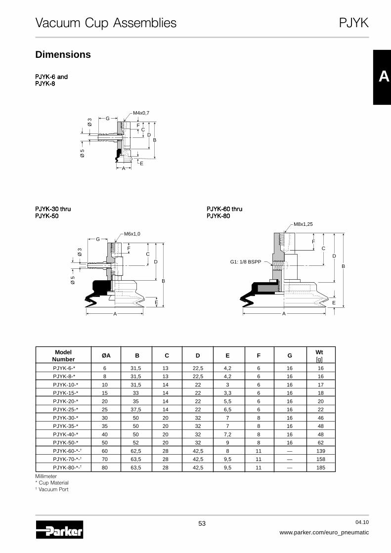
Vacuum Cup Assemblies PJYK
Dimensions
Model ØA B C D E F G WtNumber [g]
PJYK-6-* 6 31,5 13 22,5 4,2 6 16 16
PJYK-8-* 8 31,5 13 22,5 4,2 6 16 16
PJYK-10-* 10 31,5 14 22 3 6 16 17
PJYK-15-* 15 33 14 22 3,3 6 16 18
PJYK-20-* 20 35 14 22 5,5 6 16 20
PJYK-25-* 25 37,5 14 22 6,5 6 16 22
PJYK-30-* 30 50 20 32 7 8 16 46
PJYK-35-* 35 50 20 32 7 8 16 48
PJYK-40-* 40 50 20 32 7,2 8 16 48
PJYK-50-* 50 52 20 32 9 8 16 62
PJYK-60-*-† 60 62,5 28 42,5 8 11 — 139
PJYK-70-*-† 70 63,5 28 42,5 9,5 11 — 158
PJYK-80-*-† 80 63,5 28 42,5 9,5 11 — 185
Millimeter* Cup Material† Vacuum Port
PJYK-60 thruPJYK-60 thruPJYK-60 thruPJYK-60 thruPJYK-60 thruPJYK-80PJYK-80PJYK-80PJYK-80PJYK-80
B
F
G1: 1/8 BSPP
C
D
E
A
M8x1,25
PJYK-30 thruPJYK-30 thruPJYK-30 thruPJYK-30 thruPJYK-30 thruPJYK-50PJYK-50PJYK-50PJYK-50PJYK-50
B
F
G
C
D
E
Ø 5
Ø 3
A
M6x1,0
PJYK-6 andPJYK-6 andPJYK-6 andPJYK-6 andPJYK-6 andPJYK-8PJYK-8PJYK-8PJYK-8PJYK-8
FC
DB
E
Ø 5
Ø 3
M4x0,7G
A
54 04.10
www.parker.com/euro_pneumatic
Vacuum Cup Assemblies PJTYS
MountingThread.
InstallationNote:Note:Note:Note:Note:When installing cup assemblies,use a sealant material to securethe assembly and preventvacuum leakage.
PJTYS Vacuum Cup Assemblies
Cup Diameter Stroke[mm] [mm]6 68 810 10
3, 10, 15
15 1520 2025 2530 30
6, 15, 3035 3540 4050 5060 6070 70 30, 50, 7080 80
Cup MaterialNBR Nitrile
RubberSI Silicone
Model Number IndexPJTYS 10 3 NBR M5
VacuumPort
M5 M5G1 1/8 BSPPSee Chart
Below
Bulkhead Level Compensator for PJG Cups
Compression ForceCompression ForceCompression ForceCompression ForceCompression ForceF1
0%of Stroke
100%of Stroke
F2
PJG Cup Diameter [mm] FTYS Fitting Part Number Vacuum PortsF1 F2N N
6 FTYS-5A-3-M5 0,49 0,598 FTYS-5A-10-M5 M5x0,8 Female 0,61 1,17
FTYS-5A-15-M5 0,64 1,17
10 JTYS-10-3-M5 0,49 0,5915 JTYS-10-10-M5 M5x0,8 Female 2,5 4,9
JTYS-10-15-M5 2,9 5,920 JTYS-20-6-M5 2,5 3,425 JTYS-20-15-M5 M5x0,8 Female 2,5 4,9
JTYS-20-30-M5 2,9 5,930 FTYS-20B-6-M5 2,5 3,435 FTYS-20B-15-M5 M5x0,8 Female 2,5 4,940 FTYS-20B-30-M5 2,9 5,950 FTYS-50-6-M5 2,5 3,4
FTYS-50-15-M5 M5x0,8 Female 2,5 4,9FTYS-50-30-M5 2,9 5,9
60 FTYS-60-30-G1 6,8 15,670 FTYS-60-50-G1 G1: 1/8 BSPP 8,3 19,680 FTYS-60-70-G1 9,5 21
More materials on request.Please see page 8 formaterial specifications.
55 04.10
www.parker.com/euro_pneumatic
A
Vacuum Cup Assemblies PJTYS
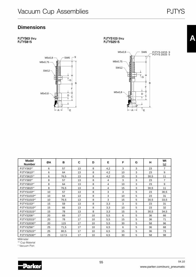
PJTYS63 thruPJTYS63 thruPJTYS63 thruPJTYS63 thruPJTYS63 thruPJTYS815PJTYS815PJTYS815PJTYS815PJTYS815
M5x0,8
M5x0,8
SW6
SW12
M8x0,75
B
D C
F
9
H
G
EA
Dimensions
PJTYS103 thruPJTYS103 thruPJTYS103 thruPJTYS103 thruPJTYS103 thruPJTYS2515PJTYS2515PJTYS2515PJTYS2515PJTYS2515
M5x0,8
M5x0,8
SW6 PJTYS-10/15 9PJTYS 20/25 5
SW12
M8x0,75
B
DC
F
HG
EA
Model ØA B C D E F G H WtNumber [g]
PJTYS63*† 6 57 13 8 4,2 3 3 23 7
PJTYS610*† 6 64 13 8 4,2 10 3 23 9
PJTYS615*† 6 76,5 13 8 4,2 15 3 30,5 11
PJTYS83*† 8 57 13 8 4 3 3 23 7
PJTYS810*† 8 64 13 8 4 10 3 23 9
PJTYS815*† 8 76,5 13 8 4 15 3 30,5 11
PJTYS103*† 10 57 13 8 3 3 5 23 30,5
PJTYS1010*† 10 64 13 8 3 10 5 23 31
PJTYS1015*† 10 76,5 13 8 3 15 5 30,5 33,5
PJTYS153*† 15 59 13 8 3,3 3 5 23 31
PJTYS1510*† 15 66 13 8 3,3 10 5 23 32
PJTYS1515*† 15 78 13 8 3,3 15 5 30,5 34,5
PJTYS206*† 20 69 17 10 5,5 6 5 36 66
PJTYS2015*† 20 78 17 10 5,5 15 5 36 71
PJTYS2030*† 20 115 17 10 5,5 30 5 58 96
PJTYS256*† 25 71,5 17 10 6,5 6 5 36 68
PJTYS2515*† 25 80,5 17 10 6,5 15 5 36 73
PJTYS2530*† 25 117,5 17 10 6,5 30 5 58 98
Millimeter** Cup Material† Vacuum Port
56 04.10
www.parker.com/euro_pneumatic
Vacuum Cup Assemblies PJTYS
Dimensions
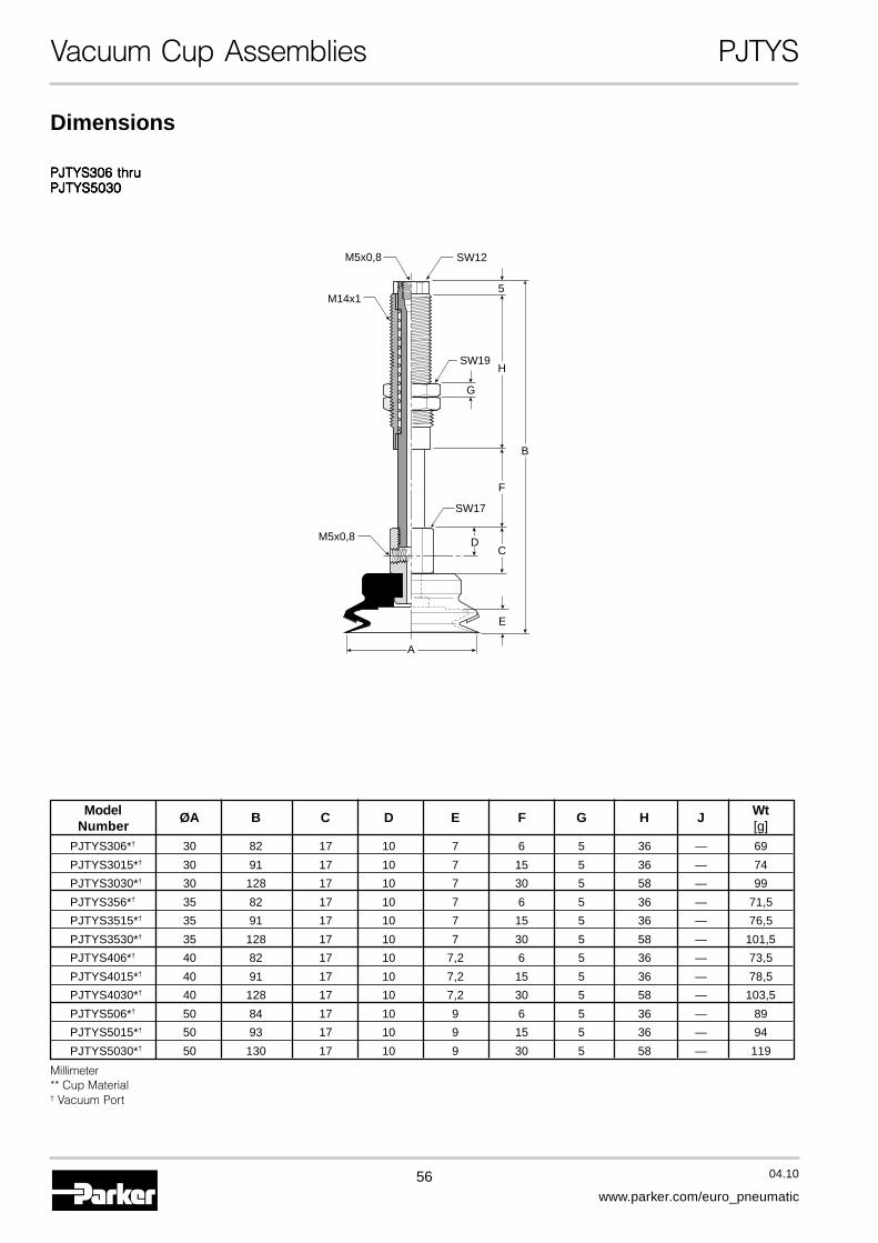
PJTYS306 thruPJTYS306 thruPJTYS306 thruPJTYS306 thruPJTYS306 thruPJTYS5030PJTYS5030PJTYS5030PJTYS5030PJTYS5030
M5x0,8
M5x0,8
SW12
SW19
SW17
M14x1
B
D
E
C
H
5
F
G
A
Model ØA B C D E F G H J WtNumber [g]
PJTYS306*† 30 82 17 10 7 6 5 36 — 69
PJTYS3015*† 30 91 17 10 7 15 5 36 — 74
PJTYS3030*† 30 128 17 10 7 30 5 58 — 99
PJTYS356*† 35 82 17 10 7 6 5 36 — 71,5
PJTYS3515*† 35 91 17 10 7 15 5 36 — 76,5
PJTYS3530*† 35 128 17 10 7 30 5 58 — 101,5
PJTYS406*† 40 82 17 10 7,2 6 5 36 — 73,5
PJTYS4015*† 40 91 17 10 7,2 15 5 36 — 78,5
PJTYS4030*† 40 128 17 10 7,2 30 5 58 — 103,5
PJTYS506*† 50 84 17 10 9 6 5 36 — 89
PJTYS5015*† 50 93 17 10 9 15 5 36 — 94
PJTYS5030*† 50 130 17 10 9 30 5 58 — 119
Millimeter** Cup Material† Vacuum Port
57 04.10
www.parker.com/euro_pneumatic
A
Vacuum Cup Assemblies PJTYS
Dimensions
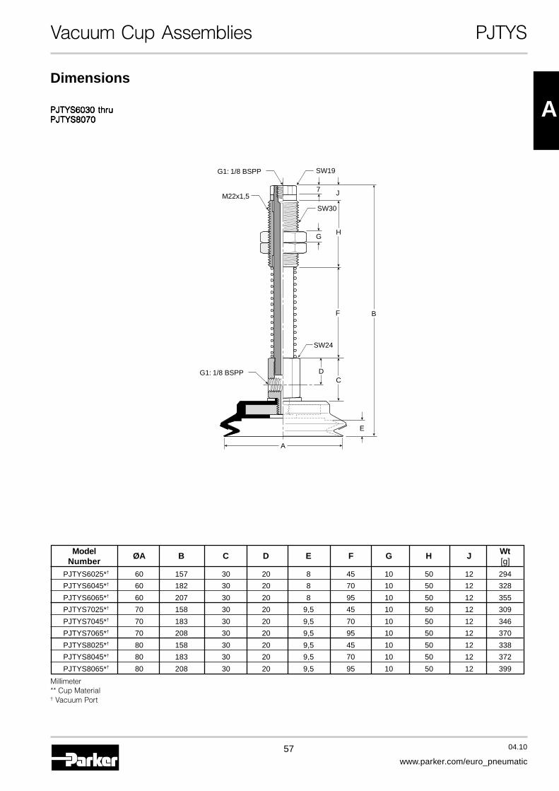
PJTYS6030 thruPJTYS6030 thruPJTYS6030 thruPJTYS6030 thruPJTYS6030 thruPJTYS8070PJTYS8070PJTYS8070PJTYS8070PJTYS8070
G1: 1/8 BSPP
G1: 1/8 BSPP
SW19
SW30
SW24
M22x1,5
B
D
E
C
H
J7
F
G
A
Model ØA B C D E F G H J WtNumber [g]
PJTYS6025*† 60 157 30 20 8 45 10 50 12 294
PJTYS6045*† 60 182 30 20 8 70 10 50 12 328
PJTYS6065*† 60 207 30 20 8 95 10 50 12 355
PJTYS7025*† 70 158 30 20 9,5 45 10 50 12 309
PJTYS7045*† 70 183 30 20 9,5 70 10 50 12 346
PJTYS7065*† 70 208 30 20 9,5 95 10 50 12 370
PJTYS8025*† 80 158 30 20 9,5 45 10 50 12 338
PJTYS8045*† 80 183 30 20 9,5 70 10 50 12 372
PJTYS8065*† 80 208 30 20 9,5 95 10 50 12 399
Millimeter** Cup Material† Vacuum Port
58 04.10
www.parker.com/euro_pneumatic
Vacuum Cups PCG
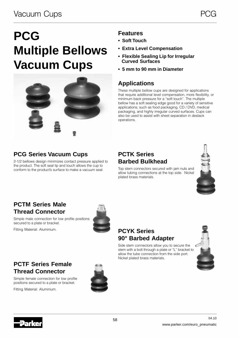
PCGMultiple BellowsVacuum Cups
Features• Soft Touch
• Extra Level Compensation
• Flexible Sealing Lip for IrregularCurved Surfaces
• 5 mm to 90 mm in Diameter
ApplicationsThese multiple bellow cups are designed for applicationsthat require additional level compensation, more flexibility, orminimum back pressure for a “soft touch”. The multiplebellow has a soft sealing edge good for a variety of sensitiveapplications; such as food packaging, CD / DVD, medicalpackaging, and highly irregular curved surfaces. Cups canalso be used to assist with sheet separation in destackoperations.
PCG Series Vacuum Cups2-1/2 bellows design minimizes contact pressure applied tothe product. The soft seal lip and touch allows the cup toconform to the product’s surface to make a vacuum seal.
PCTM Series MaleThread ConnectorSimple male connection for low profile positionssecured to a plate or bracket.
Fitting Material: Aluminium.
PCTF Series FemaleThread ConnectorSimple female connection for low profilepositions secured to a plate or bracket.
Fitting Material: Aluminium.
PCTK SeriesBarbed BulkheadTop stem connectors secured with jam nuts andallow tubing connections at the top side. Nickelplated brass materials.
PCYK Series90° Barbed AdapterSide stem connectors allow you to secure thestem with a bolt through a plate or “L” bracket toallow the tube connection from the side port.Nickel plated brass materials.

59 04.10
www.parker.com/euro_pneumatic
A
Vacuum Cups PCG
PCG - 5 - NBR
Cup Diameter [mm]5 5 20 207 7 30 30
10 10 40 4015 15 60 6018 18 90 90
Model Number Index
Cup MaterialNBR Nitrile RubberSI SiliconeU Urethane*
Application Guide2-1/2 Bellows
• Destack Perimeter Separation • Controlling downstrokelifts product on contact
• Level Compensation for applicationswhere Level Compensators do not haveadequate space
More materials on request.Please see page 8 formaterial specifications.* Not available for Ø 90.
60 04.10
www.parker.com/euro_pneumatic
Vacuum Cups PCG
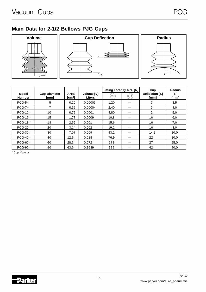
Main Data for 2-1/2 Bellows PJG Cups
S RV
Volume RadiusCup Deflection
Lifting Force @ 60% [N] Cup RadiusModel Cup Diameter Area Volume [V] Deflection [S] R
Number [mm] [cm2] Liters [mm] [mm]
PCG-5-* 5 0,20 0,00003 1,20 — 3 3,5
PCG-7-* 7 0,39 0,00004 2,40 — 3 4,0
PCG-10-* 10 0,79 0,0001 4,80 — 3 5,0
PCG-15-* 15 1,77 0,0009 10,8 — 10 6,0
PCG-18-* 18 2,55 0,001 15,6 — 10 7,0
PCG-20-* 20 3,14 0,002 19,2 — 10 8,0
PCG-30-* 30 7,07 0,009 43,2 — 14,5 20,0
PCG-40-* 40 12,6 0,018 76,9 — 22 30,0
PCG-60-* 60 28,3 0,072 173 — 27 55,0
PCG-90-* 90 63,6 0,1639 389 — 42 80,0
* Cup Material
61 04.10
www.parker.com/euro_pneumatic
A
Vacuum Cups PCG
PCG-30 thruPCG-30 thruPCG-30 thruPCG-30 thruPCG-30 thruPCG-60PCG-60PCG-60PCG-60PCG-60
PCG-90PCG-90PCG-90PCG-90PCG-90
A
E
F
BJ
HG
A
E
F
HG
B
J
Dimensions
PCG-5 andPCG-5 andPCG-5 andPCG-5 andPCG-5 andPCG-7PCG-7PCG-7PCG-7PCG-7
EF
DJ
CA
B
G
H
PCG-10 thruPCG-10 thruPCG-10 thruPCG-10 thruPCG-10 thruPCG-20PCG-20PCG-20PCG-20PCG-20
A
E
F
BJ
H
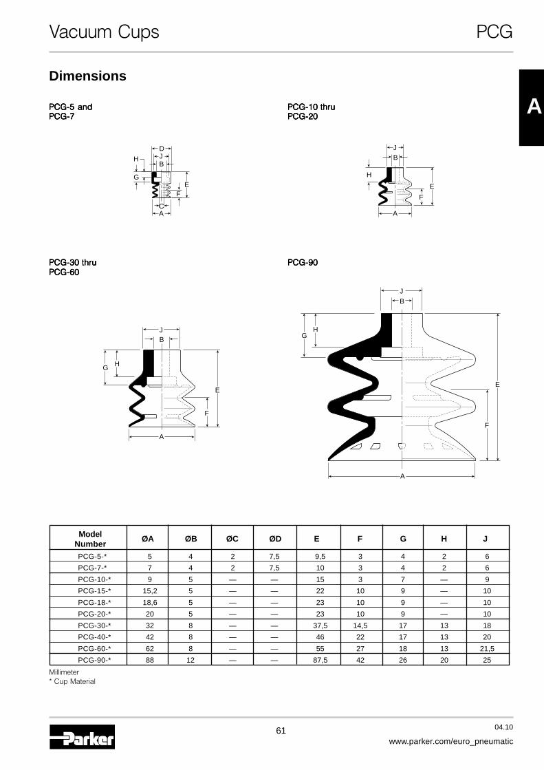
Model ØA ØB ØC ØD E F G H JNumberPCG-5-* 5 4 2 7,5 9,5 3 4 2 6
PCG-7-* 7 4 2 7,5 10 3 4 2 6
PCG-10-* 9 5 — — 15 3 7 — 9
PCG-15-* 15,2 5 — — 22 10 9 — 10
PCG-18-* 18,6 5 — — 23 10 9 — 10
PCG-20-* 20 5 — — 23 10 9 — 10
PCG-30-* 32 8 — — 37,5 14,5 17 13 18
PCG-40-* 42 8 — — 46 22 17 13 20
PCG-60-* 62 8 — — 55 27 18 13 21,5
PCG-90-* 88 12 — — 87,5 42 26 20 25
Millimeter* Cup Material

62 04.10
www.parker.com/euro_pneumatic
Vacuum Cup Assemblies PCTM
Male Threaded Fitting for PCG Cups
PCTM Vacuum Cup Assemblies
MountingThread.
InstallationNote:Note:Note:Note:Note:When installing cup assemblies,use a sealant material to securethe assembly and preventvacuum leakage.
Cup MaterialNBR Nitrile
RubberSI SiliconeU Urethane*
Model Number IndexPCTM - 5 - NBR - M5
MountingThread
M5 M5G1 1/8 BSPPG2 1/4 BSPPSee Chart
Below
Cup Diameter [mm]5 5 20 207 7 30 30
10 10 40 4015 15 60 6018 18 90 90
Millimeter
PCG Cup Diameter [mm] FTM & CTM Part Number Mounting Thread
5 FTM-5A-M5 M5x0,8 Male
7 FTM-5A-G1 1/8 BSPP Male
10
15 CTM-10-M5 M5x0,8 Male
18 CTM-10-G1 1/8 BSPP Male
20
30
40 CTM-30-G1 1/8 BSPP Male
60 CTM-30-G2 1/4 BSPP Male
90 CTM-90-G2 1/4 BSPP Male
More materials on request.Please see page 8 formaterial specifications.* Not available for Ø 90.
63 04.10
www.parker.com/euro_pneumatic
A
SW8
M5: M5G1: 1/8 BSPP
E
B
CD
A A
B
E
C
D
5/16"
M5: M5G1: 1/8 BSPP
PCTM-5 andPCTM-5 andPCTM-5 andPCTM-5 andPCTM-5 andPCTM-7PCTM-7PCTM-7PCTM-7PCTM-7
PCTM-10 thruPCTM-10 thruPCTM-10 thruPCTM-10 thruPCTM-10 thruPCTM-20PCTM-20PCTM-20PCTM-20PCTM-20
Vacuum Cup Assemblies PCTM
PCTM-90PCTM-90PCTM-90PCTM-90PCTM-90PCTM-30 thruPCTM-30 thruPCTM-30 thruPCTM-30 thruPCTM-30 thruPCTM-60PCTM-60PCTM-60PCTM-60PCTM-60
A
B
E
G1: 1/8 BSPPG2: 1/4 BSPP
1/2"C
D
B
E
G2: 1/4 BSPP
9/16"C
D
A
Dimensions
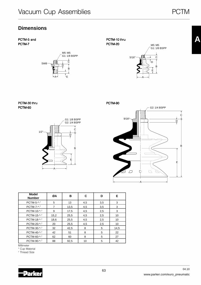
Model ØA B C D ENumber
PCTM-5-*-† 5 13 4,5 3,5 3
PCTM-7-*-† 7 13,5 4,5 3,5 3
PCTM-10-*-† 9 17,5 4,5 2,5 3
PCTM-15-*-† 15,2 25,5 4,5 2,5 10
PCTM-18-*-† 18,6 25,5 4,5 2,5 10
PCTM-20-*-† 20 25,5 4,5 2,5 10
PCTM-30-*-† 32 42,5 8 5 14,5
PCTM-40-*-† 42 51 8 5 22
PCTM-60-*-† 62 60 8 5 27
PCTM-90-*-† 88 92,5 10 5 42
Millimeter* Cup Material† Thread Size
64 04.10
www.parker.com/euro_pneumatic
Vacuum Cup Assemblies PCTF
Female Threaded Fitting for PCG Cups
PCTF Vacuum Cup Assemblies
Installation Mounting
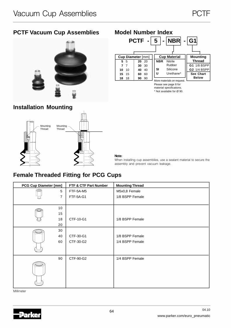
Model Number IndexPCTF - 5 - NBR - G1
MountingThread
MountingThread
Note:Note:Note:Note:Note:When installing cup assemblies, use a sealant material to secure theassembly and prevent vacuum leakage.
Cup MaterialNBR Nitrile
RubberSI SiliconeU Urethane*
MountingThread
G1 1/8 BSPPG2 1/4 BSPPSee Chart
Below
Cup Diameter [mm]5 5 20 207 7 30 30
10 10 40 4015 15 60 6018 18 90 90
Millimeter
PCG Cup Diameter [mm] FTF & CTF Part Number Mounting Thread
5 FTF-5A-M5 M5x0,8 Female
7 FTF-5A-G1 1/8 BSPP Female
10
15
18 CTF-10-G1 1/8 BSPP Female
20
30
40 CTF-30-G1 1/8 BSPP Female
60 CTF-30-G2 1/4 BSPP Female
90 CTF-90-G2 1/4 BSPP Female
More materials on request.Please see page 8 formaterial specifications.* Not available for Ø 90.
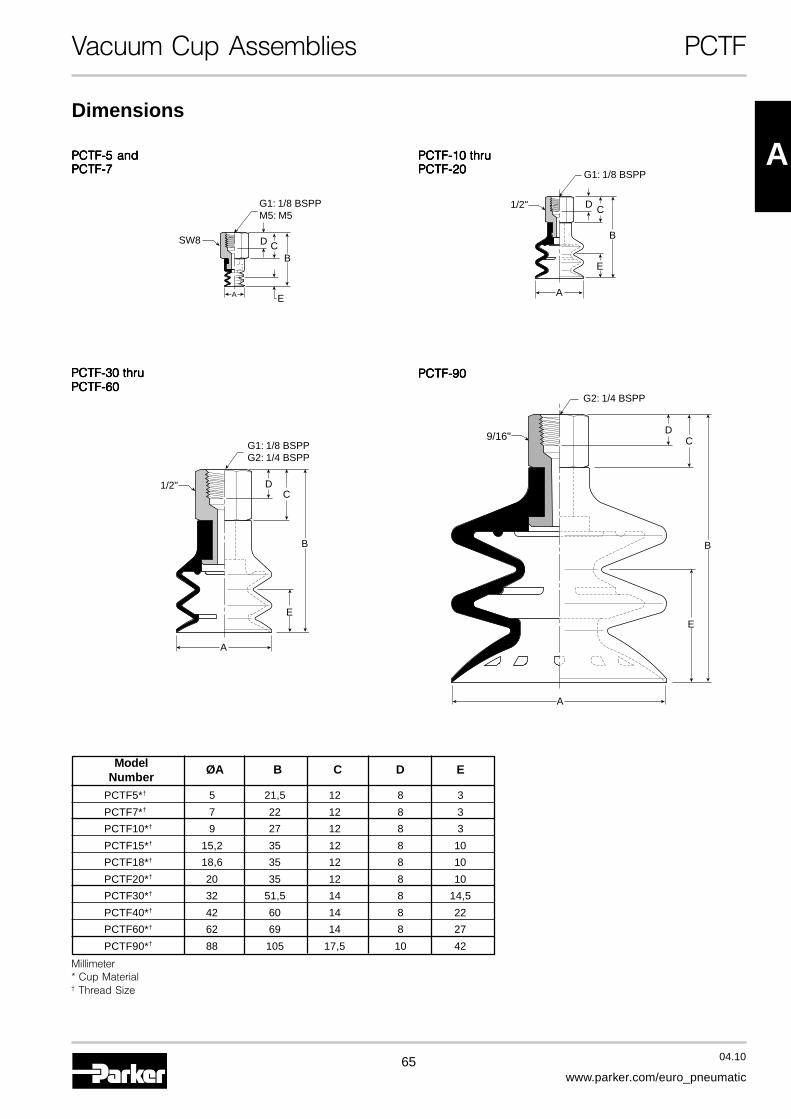
65 04.10
www.parker.com/euro_pneumatic
APCTF-5 andPCTF-5 andPCTF-5 andPCTF-5 andPCTF-5 andPCTF-7PCTF-7PCTF-7PCTF-7PCTF-7
PCTF-10 thruPCTF-10 thruPCTF-10 thruPCTF-10 thruPCTF-10 thruPCTF-20PCTF-20PCTF-20PCTF-20PCTF-20
Vacuum Cup Assemblies PCTF
PCTF-90PCTF-90PCTF-90PCTF-90PCTF-90PCTF-30 thruPCTF-30 thruPCTF-30 thruPCTF-30 thruPCTF-30 thruPCTF-60PCTF-60PCTF-60PCTF-60PCTF-60
E
BCD
A
G1: 1/8 BSPPM5: M5
SW8
A
B
E
CD
G1: 1/8 BSPP
1/2"
A
B
E
CD
G1: 1/8 BSPPG2: 1/4 BSPP
1/2"
B
E
CD
A
9/16"
G2: 1/4 BSPP
Dimensions
Model ØA B C D ENumber
PCTF5*† 5 21,5 12 8 3
PCTF7*† 7 22 12 8 3
PCTF10*† 9 27 12 8 3
PCTF15*† 15,2 35 12 8 10
PCTF18*† 18,6 35 12 8 10
PCTF20*† 20 35 12 8 10
PCTF30*† 32 51,5 14 8 14,5
PCTF40*† 42 60 14 8 22
PCTF60*† 62 69 14 8 27
PCTF90*† 88 105 17,5 10 42
Millimeter* Cup Material† Thread Size

66 04.10
www.parker.com/euro_pneumatic
Vacuum Cup Assemblies PCTK
Barbed Bulkhead for PCG Cups
PCTK Vacuum Cup Assemblies
Installation
MountingThread
Cup Screw
Note:Note:Note:Note:Note:When installing cup assemblies,use a sealant material to securethe assembly and preventvacuum leakage.
Model Number IndexPCTK - 5 - NBR - —
Cup MaterialNBR Nitrile
RubberSI SiliconeU Urethane*
Vacuum PortBlank Barb
G1 1/8 BSPPSee Chart
Below
Cup Diameter [mm]5 5 20 207 7 30 30
10 10 40 4015 15 60 6018 18 90 90
Millimeter
PCG Cup Diameter [mm] FTK & CTK Part Number Mounting Thread
5FTK-5A M9x1 Male
7
10
15CTK-10 M8x1,25 Male
18
20
30
40 CTK-30 M10x1,5 Male
60
90 CTK-90-G1 M16x1,5 Male
More materials on request.Please see page 8 formaterial specifications.* Not available for Ø 90.

67 04.10
www.parker.com/euro_pneumatic
A
Vacuum Cup Assemblies PCTK
Dimensions
Model ØA B C D E F G WtNumber [g]
PCTK-5-* 5 33,5 10 14 3 12 3 11
PCTK-7-* 7 34 10 14 3 12 3 11
PCTK-10-* 9 56,2 16 22,5 3 15 4 22
PCTK-15-* 15,2 64,2 16 22 10 15 4 22
PCTK-18-* 18,6 64,2 16 22 10 15 4 22
PCTK-20-* 20 64,2 16 22 10 15 4 22
PCTK-30-* 32 86,8 16 32 14,5 20 5 46
PCTK-40-* 42 95,3 16 32 22 20 5 55
PCTK-60-* 62 104,3 16 32 27 20 5 85
PCTK-90-*-† 88 144,8 — 42,5 42 23 6 300
Millimeter* Cup Material† Vacuum Port
PCTK-90PCTK-90PCTK-90PCTK-90PCTK-90G1: 1/8 BSPP
G1: 1/8 BSPP
SW21
M16x1,5
B
FG
D
A
E
PCTK-5 andPCTK-5 andPCTK-5 andPCTK-5 andPCTK-5 andPCTK-7PCTK-7PCTK-7PCTK-7PCTK-7
EA
Ø 5
Ø 2,5
FG
C
D B
M9x1,0SW12
PCTK-10 thruPCTK-10 thruPCTK-10 thruPCTK-10 thruPCTK-10 thruPCTK-20PCTK-20PCTK-20PCTK-20PCTK-20
B
FG
C
D
M8x1,25
SW12
Ø 5Ø 3
E
A
PCTK-30 thruPCTK-30 thruPCTK-30 thruPCTK-30 thruPCTK-30 thruPCTK -60PCTK -60PCTK -60PCTK -60PCTK -60
B
FG
C
D
M10x1,5
SW14
Ø 5Ø 3
A
E

68 04.10
www.parker.com/euro_pneumatic
Vacuum Cup Assemblies PCYK
90° Barbed Adapter for PCG Cups
PCYK Vacuum Cup Assemblies
Installation MountingThread
Cup Screw
Note:Note:Note:Note:Note:When installing cup assemblies,use a sealant material to securethe assembly and preventvacuum leakage.
Model Number IndexPCYK - 5 - NBR - —
Cup MaterialNBR Nitrile
RubberSI SiliconeU Urethane*
Vacuum PortBlank Barb
G1 1/8 BSPPSee Chart
Below
Cup Diameter [mm]5 5 20 207 7 30 30
10 10 40 4015 15 60 6018 18 90 90
Millimeter
PCG Cup Diameter [mm] FYK & CYK Part Number Mounting Thread
5FYK-5A M4x0,7 Female
7
10
15CYK-10 M4x0,7 Female
18
20
30
40 CYK-30 M6x1,0 Female
60
90 CYK-90-G1 M16x1,5 Female
More materials on request.Please see page 8 formaterial specifications.* Not available for Ø 90.
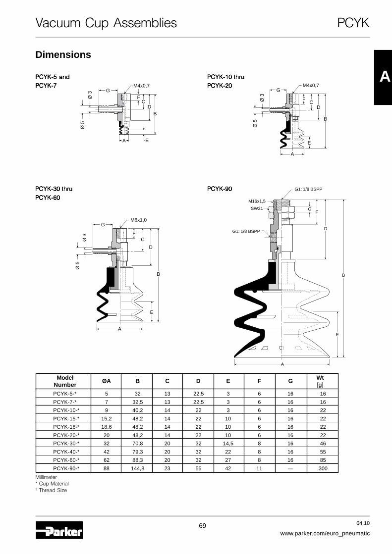
69 04.10
www.parker.com/euro_pneumatic
APCYK-5 andPCYK-5 andPCYK-5 andPCYK-5 andPCYK-5 andPCYK-7PCYK-7PCYK-7PCYK-7PCYK-7
PCYK-10 thruPCYK-10 thruPCYK-10 thruPCYK-10 thruPCYK-10 thruPCYK-20PCYK-20PCYK-20PCYK-20PCYK-20
Vacuum Cup Assemblies PCYK
PCYK-30 thruPCYK-30 thruPCYK-30 thruPCYK-30 thruPCYK-30 thru
PCYK-60PCYK-60PCYK-60PCYK-60PCYK-60
Dimensions
EA
FC
DB
Ø 5
Ø 3
M4x0,7G
A
E
B
F
GM6x1,0
C
D
Ø 5
Ø 3
E
A
B
F
GM4x0,7
CD
Ø 5
Ø 3
G1: 1/8 BSPP
G1: 1/8 BSPP
SW21
M16x1,5
B
FG
D
A
E
PCYK-90PCYK-90PCYK-90PCYK-90PCYK-90
Model ØA B C D E F G WtNumber [g]
PCYK-5-* 5 32 13 22,5 3 6 16 16
PCYK-7-* 7 32,5 13 22,5 3 6 16 16
PCYK-10-* 9 40,2 14 22 3 6 16 22
PCYK-15-* 15,2 48,2 14 22 10 6 16 22
PCYK-18-* 18,6 48,2 14 22 10 6 16 22
PCYK-20-* 20 48,2 14 22 10 6 16 22
PCYK-30-* 32 70,8 20 32 14,5 8 16 46
PCYK-40-* 42 79,3 20 32 22 8 16 55
PCYK-60-* 62 88,3 20 32 27 8 16 85
PCYK-90-* 88 144,8 23 55 42 11 — 300
Millimeter* Cup Material† Thread Size
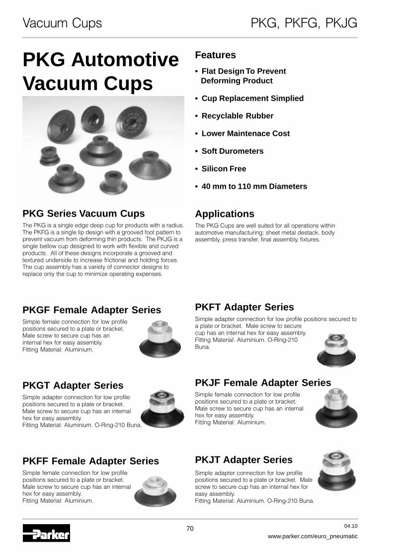
70 04.10
www.parker.com/euro_pneumatic
Vacuum Cups PKG, PKFG, PKJG
PKG AutomotiveVacuum Cups
PKG Series Vacuum CupsThe PKG is a single edge deep cup for products with a radius.The PKFG is a single lip design with a grooved foot pattern toprevent vacuum from deforming thin products. The PKJG is asingle bellow cup designed to work with flexible and curvedproducts. All of these designs incorporate a grooved andtextured underside to increase frictional and holding forces.The cup assembly has a variety of connector designs toreplace only the cup to minimize operating expenses.
PKGF Female Adapter SeriesSimple female connection for low profilepositions secured to a plate or bracket.Male screw to secure cup has aninternal hex for easy assembly.Fitting Material: Aluminium.
PKGT Adapter SeriesSimple adapter connection for low profilepositions secured to a plate or bracket.Male screw to secure cup has an internalhex for easy assembly.Fitting Material: Aluminium. O-Ring-210 Buna.
PKFF Female Adapter SeriesSimple female connection for low profilepositions secured to a plate or bracket.Male screw to secure cup has an internalhex for easy assembly.Fitting Material: Aluminium.
Features
• Flat Design To PreventDeforming Product
• Cup Replacement Simplied
• Recyclable Rubber
• Lower Maintenace Cost
• Soft Durometers
• Silicon Free
• 40 mm to 110 mm Diameters
ApplicationsThe PKG Cups are well suited for all operations withinautomotive manufacturing; sheet metal destack, bodyassembly, press transfer, final assembly, fixtures.
PKFT Adapter SeriesSimple adapter connection for low profile positions secured toa plate or bracket. Male screw to securecup has an internal hex for easy assembly.Fitting Material: Aluminium. O-Ring-210Buna.
PKJF Female Adapter SeriesSimple female connection for low profilepositions secured to a plate or bracket.Male screw to secure cup has an internalhex for easy assembly.Fitting Material: Aluminium.
PKJT Adapter SeriesSimple adapter connection for low profilepositions secured to a plate or bracket. Malescrew to secure cup has an internal hex foreasy assembly.Fitting Material: Aluminium. O-Ring-210 Buna.
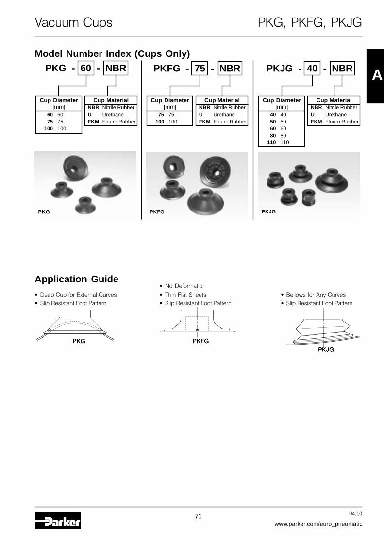
71 04.10
www.parker.com/euro_pneumatic
A
Vacuum Cups PKG, PKFG, PKJG
Model Number Index (Cups Only)
PKG - 60 - NBR
Cup Diameter[mm]
60 6075 75
100 100
Cup MaterialNBR Nitrile RubberU UrethaneFKM Flouro Rubber
PKJG - 40 - NBRPKFG - 75 - NBR
Cup Diameter[mm]
75 75100 100
Cup MaterialNBR Nitrile RubberU UrethaneFKM Flouro Rubber
Cup Diameter[mm]
40 4050 5060 6080 80
110 110
Cup MaterialNBR Nitrile RubberU UrethaneFKM Flouro Rubber
PKFGPKG PKJG
Application Guide• Deep Cup for External Curves
• Slip Resistant Foot Pattern
• No Deformation
• Thin Flat Sheets
• Slip Resistant Foot Pattern
• Bellows for Any Curves
• Slip Resistant Foot Pattern
PKGPKGPKGPKGPKG PKFGPKFGPKFGPKFGPKFGPKJGPKJGPKJGPKJGPKJG
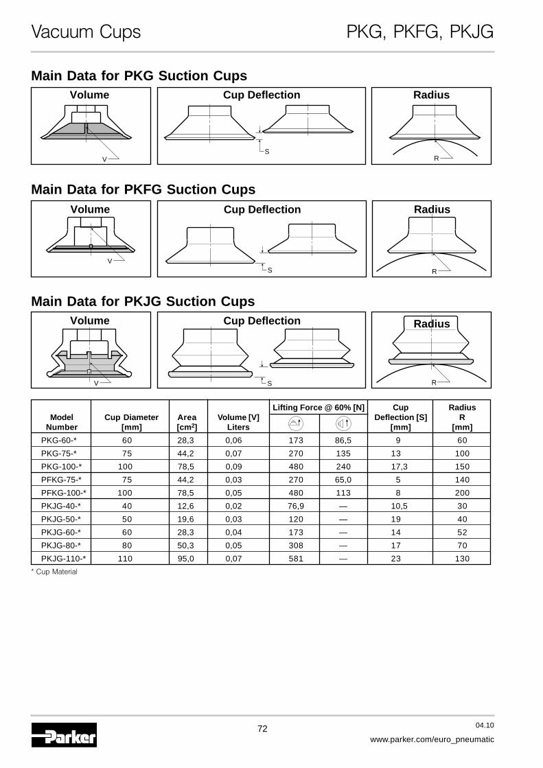
72 04.10
www.parker.com/euro_pneumatic
Vacuum Cups PKG, PKFG, PKJG
Main Data for PKJG Suction Cups
S R
Volume RadiusCup Deflection
V
Main Data for PKG Suction Cups
SR
Volume RadiusCup Deflection
V
Main Data for PKFG Suction Cups
S R
Volume RadiusCup Deflection
V
Lifting Force @ 60% [N] Cup RadiusModel Cup Diameter Area Volume [V] Deflection [S] R
Number [mm] [cm2] Liters [mm] [mm]
PKG-60-* 60 28,3 0,06 173 86,5 9 60
PKG-75-* 75 44,2 0,07 270 135 13 100
PKG-100-* 100 78,5 0,09 480 240 17,3 150
PFKG-75-* 75 44,2 0,03 270 65,0 5 140
PFKG-100-* 100 78,5 0,05 480 113 8 200
PKJG-40-* 40 12,6 0,02 76,9 — 10,5 30
PKJG-50-* 50 19,6 0,03 120 — 19 40
PKJG-60-* 60 28,3 0,04 173 — 14 52
PKJG-80-* 80 50,3 0,05 308 — 17 70
PKJG-110-* 110 95,0 0,07 581 — 23 130
* Cup Material
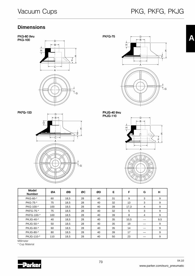
73 04.10
www.parker.com/euro_pneumatic
A
Vacuum Cups PKG, PKFG, PKJG
Dimensions
AC
B
D
F
G
H
E
PKG-60 thruPKG-60 thruPKG-60 thruPKG-60 thruPKG-60 thruPKG-100PKG-100PKG-100PKG-100PKG-100
PKJG-40 thruPKJG-40 thruPKJG-40 thruPKJG-40 thruPKJG-40 thruPKJG-110PKJG-110PKJG-110PKJG-110PKJG-110
PKFG-75PKFG-75PKFG-75PKFG-75PKFG-75
AC
BD
F
G
H
E
AC
BD
H
F
E
PKFG-100PKFG-100PKFG-100PKFG-100PKFG-100
BD
G
H
AC
F
E
Model ØA ØB ØC ØD E F G HNumber
PKG-60-* 60 18,5 28 40 31 9 3 9
PKG-75-* 75 18,5 28 40 32 13 3 9
PKG-100-* 100 18,5 28 40 39 17,3 4 9
PKFG-75-* 75 18,5 28 40 32 5 3 9
PKFG-100-* 100 18,5 28 40 39 8 4 9
PKJG-40-* 40 18,5 28 40 35 10,5 — 9,5
PKJG-50-* 50 18,5 28 40 35 19 — 9
PKJG-60-* 60 18,5 28 40 35 14 — 9
PKJG-80-* 80 18,5 28 40 39 17 — 9
PKJG-110-* 110 18,5 28 40 50 23 — 9
Millimeter* Cup Material
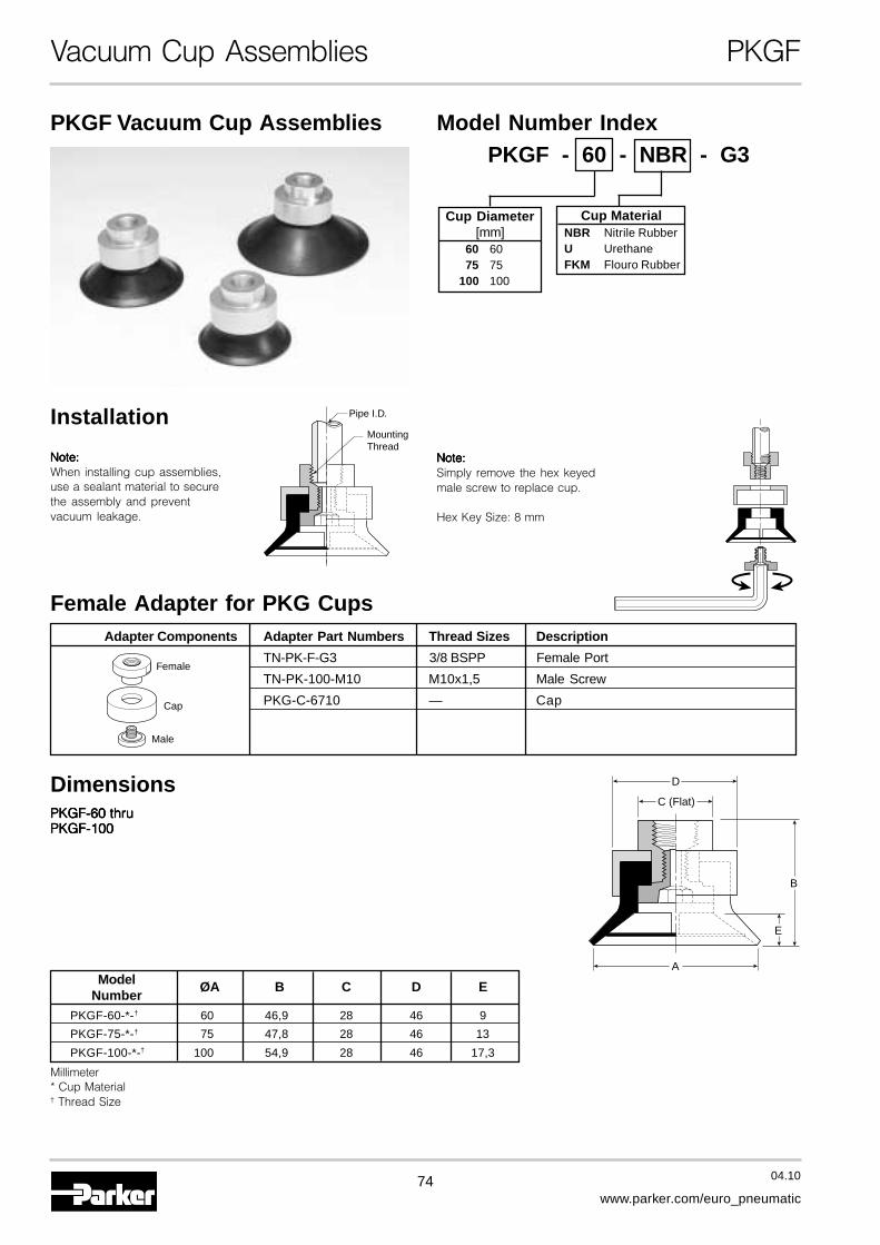
74 04.10
www.parker.com/euro_pneumatic
Vacuum Cup Assemblies PKGF
Female Adapter for PKG Cups
PKGF Vacuum Cup Assemblies
Installation
PKGF-60 thruPKGF-60 thruPKGF-60 thruPKGF-60 thruPKGF-60 thruPKGF-100PKGF-100PKGF-100PKGF-100PKGF-100
Dimensions
Note:Note:Note:Note:Note:When installing cup assemblies,use a sealant material to securethe assembly and preventvacuum leakage.
A
D
C (Flat)
E
B
Pipe I.D.
MountingThread
Note:Note:Note:Note:Note:Simply remove the hex keyedmale screw to replace cup.
Hex Key Size: 8 mm
Model ØA B C D ENumber
PKGF-60-*-† 60 46,9 28 46 9
PKGF-75-*-† 75 47,8 28 46 13
PKGF-100-*-† 100 54,9 28 46 17,3
Millimeter* Cup Material† Thread Size
Adapter Components Adapter Part Numbers Thread Sizes Description
TN-PK-F-G3 3/8 BSPP Female Port
TN-PK-100-M10 M10x1,5 Male Screw
PKG-C-6710 — Cap
Female
Cap
Male
Cup Diameter[mm]
60 6075 75
100 100
Model Number IndexPKGF - 60 - NBR - G3
Cup MaterialNBR Nitrile RubberU UrethaneFKM Flouro Rubber

75 04.10
www.parker.com/euro_pneumatic
A
Vacuum Cup Assemblies PKGT
Adapter for PKG Cups
PKGT Vacuum Cup Assemblies
Installation
PKGTPKGTPKGTPKGTPKGT-60 and-60 and-60 and-60 and-60 andPKGTPKGTPKGTPKGTPKGT-100-100-100-100-100
Dimensions
Note:Note:Note:Note:Note:When installing cup assemblies,use a sealant material to securethe assembly and preventvacuum leakage.
A
DC (Square)
E
B
Note:Note:Note:Note:Note:Simply remove the hex keyedmale screw to replace cup.
Hex Key Size: 8 mm
Adapter Components Adapter Part Numbers Thread Sizes Description
TN-PK-T — Adapter / O-ring
PKG-C-6710 — Cap
TN-PK-100-M10 M10x1,5 Male ScrewCap
Adapter
Male
Model ØA B C D ENumber
PKGT-60-* 60 34 28 46 1,1
PKGT-75-* 75 35 28 46 1,1
PKGT-100-* 100 42 28 46 1,3
Millimeter* Cup Material
Model Number IndexPKGT - 60 - NBR
Cup MaterialNBR Nitrile RubberU UrethaneFKM Flouro Rubber
Cup Diameter[mm]
60 6075 75
100 100
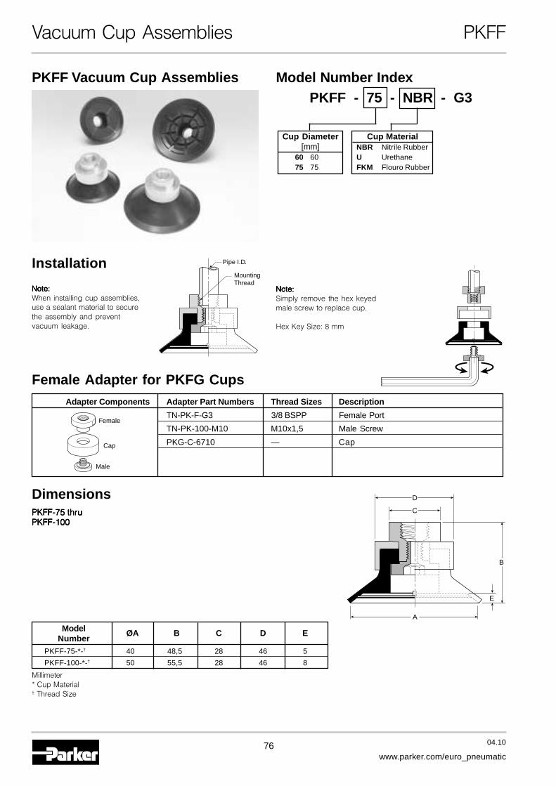
76 04.10
www.parker.com/euro_pneumatic
Vacuum Cup Assemblies PKFF
PKFF Vacuum Cup Assemblies
PKFF-75 thruPKFF-75 thruPKFF-75 thruPKFF-75 thruPKFF-75 thruPKFF-100PKFF-100PKFF-100PKFF-100PKFF-100
Dimensions
Female Adapter for PKFG Cups
Installation
Note:Note:Note:Note:Note:When installing cup assemblies,use a sealant material to securethe assembly and preventvacuum leakage.
D
C
E
B
A
Pipe I.D.
MountingThread
Note:Note:Note:Note:Note:Simply remove the hex keyedmale screw to replace cup.
Hex Key Size: 8 mm
Adapter Components Adapter Part Numbers Thread Sizes Description
TN-PK-F-G3 3/8 BSPP Female Port
TN-PK-100-M10 M10x1,5 Male Screw
PKG-C-6710 — Cap
Female
Cap
Male
Model ØA B C D ENumber
PKFF-75-*-† 40 48,5 28 46 5
PKFF-100-*-† 50 55,5 28 46 8
Millimeter* Cup Material† Thread Size
Model Number IndexPKFF - 75 - NBR - G3
Cup MaterialNBR Nitrile RubberU UrethaneFKM Flouro Rubber
Cup Diameter[mm]
60 6075 75
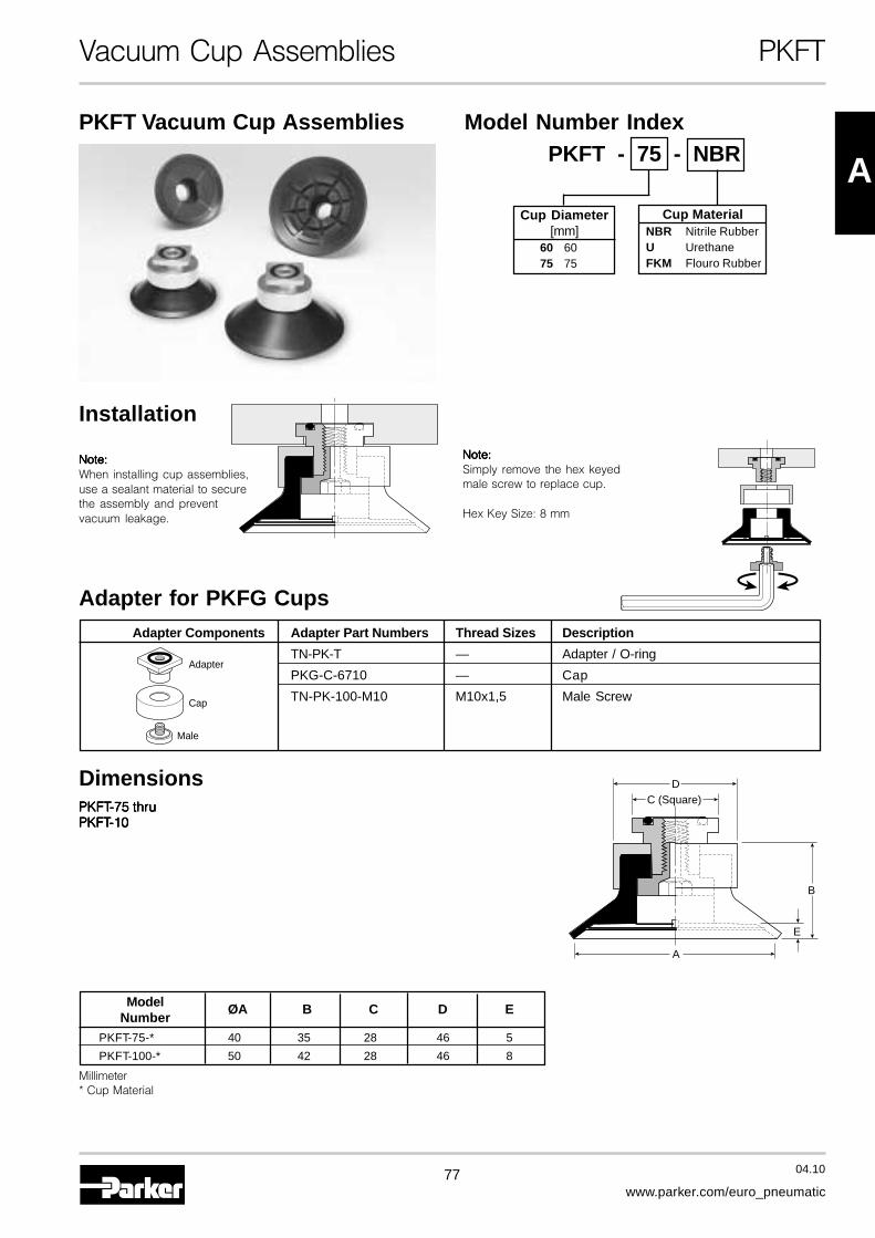
77 04.10
www.parker.com/euro_pneumatic
A
Vacuum Cup Assemblies PKFT
PKFT Vacuum Cup Assemblies
PKFTPKFTPKFTPKFTPKFT-75 thru-75 thru-75 thru-75 thru-75 thruPKFTPKFTPKFTPKFTPKFT-10-10-10-10-10
Dimensions
Adapter for PKFG Cups
Installation
Note:Note:Note:Note:Note:When installing cup assemblies,use a sealant material to securethe assembly and preventvacuum leakage.
DC (Square)
B
E
A
Note:Note:Note:Note:Note:Simply remove the hex keyedmale screw to replace cup.
Hex Key Size: 8 mm
Adapter Components Adapter Part Numbers Thread Sizes Description
TN-PK-T — Adapter / O-ring
PKG-C-6710 — Cap
TN-PK-100-M10 M10x1,5 Male ScrewCap
Adapter
Male
Model ØA B C D ENumber
PKFT-75-* 40 35 28 46 5
PKFT-100-* 50 42 28 46 8
Millimeter* Cup Material
Model Number IndexPKFT - 75 - NBR
Cup MaterialNBR Nitrile RubberU UrethaneFKM Flouro Rubber
Cup Diameter[mm]
60 6075 75
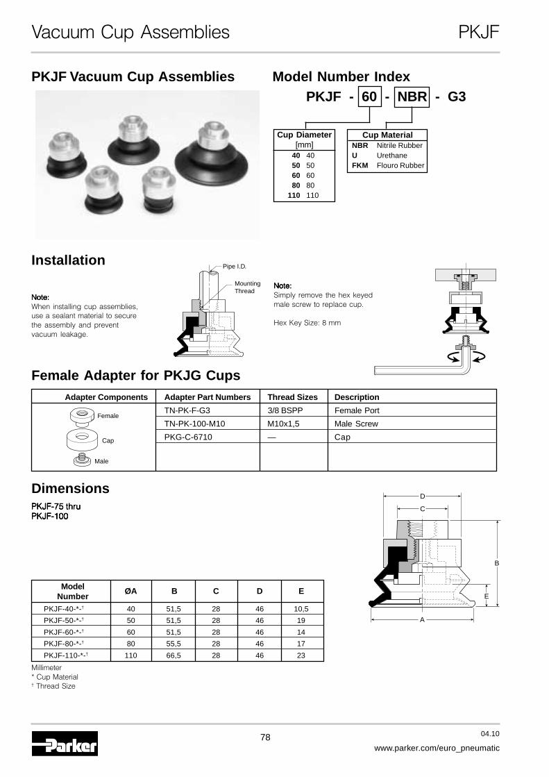
78 04.10
www.parker.com/euro_pneumatic
Vacuum Cup Assemblies PKJF
PKJF Vacuum Cup Assemblies
PKJF-75 thruPKJF-75 thruPKJF-75 thruPKJF-75 thruPKJF-75 thruPKJF-100PKJF-100PKJF-100PKJF-100PKJF-100
Dimensions
Female Adapter for PKJG Cups
Installation
Note:Note:Note:Note:Note:When installing cup assemblies,use a sealant material to securethe assembly and preventvacuum leakage.
D
C
B
A
E
Pipe I.D.
MountingThread
Note:Note:Note:Note:Note:Simply remove the hex keyedmale screw to replace cup.
Hex Key Size: 8 mm
Model Number IndexPKJF - 60 - NBR - G3
Cup Diameter[mm]
40 4050 5060 6080 80
110 110
Cup MaterialNBR Nitrile RubberU UrethaneFKM Flouro Rubber
Adapter Components Adapter Part Numbers Thread Sizes Description
TN-PK-F-G3 3/8 BSPP Female Port
TN-PK-100-M10 M10x1,5 Male Screw
PKG-C-6710 — Cap
Female
Cap
Male
Model ØA B C D ENumber
PKJF-40-*-† 40 51,5 28 46 10,5
PKJF-50-*-† 50 51,5 28 46 19
PKJF-60-*-† 60 51,5 28 46 14
PKJF-80-*-† 80 55,5 28 46 17
PKJF-110-*-† 110 66,5 28 46 23
Millimeter* Cup Material† Thread Size

79 04.10
www.parker.com/euro_pneumatic
A
Vacuum Cup Assemblies PKJT
PKJT Vacuum Cup Assemblies
PKJTPKJTPKJTPKJTPKJT-40 thru-40 thru-40 thru-40 thru-40 thru
PKJTPKJTPKJTPKJTPKJT-110-110-110-110-110
Dimensions
Adapter for PKJG Cups
Model Number IndexPKJT - 60 - NBR
Cup MaterialNBR Nitrile RubberU UrethaneFKM Flouro Rubber
Cup Diameter [mm]40 4050 5060 6080 80
110 110
Installation
Note:Note:Note:Note:Note:When installing cup assemblies,use a sealant material to securethe assembly and preventvacuum leakage.
DC (Square)
B
A
E
Note:Note:Note:Note:Note:Simply remove the hex keyedmale screw to replace cup.
Hex Key Size: 8 mm
Model ØA B C D ENumber
PKJT-40-* 40 38 28 46 10,5
PKJT-50-* 50 38 28 46 19
PKJT-60-* 60 38 28 46 14
PKJT-80-* 80 42 28 46 17
PKJT-110-* 110 53 28 46 23
Millimeter* Cup Material
Adapter Components Adapter Part Numbers Thread Sizes Description
TN-PK-T — Adapter / O-ring
PKG-C-6710 — Cap
TN-PK-100-M10 M10x1,5 Male ScrewCap
Adapter
Male

80 04.10
www.parker.com/euro_pneumatic
Vacuum Cups PUGB
PUGBFlat SwivelVacuum Cups
Features
• Internal Swivel Joint Design
• 30° Inclusive Angle for Flexible Products
• Increased Stability for Horizontal Lifts
• Lower Maintenance Costs
• 10 mm to 200 mm Diameters
ApplicationsThe single edge swivel cup is for smooth surfaces with slightlycurved surfaces or flexible sheets with substantial weights.Typically, lift capacities and break away forces are higher forflat cups which may be necessary for good stability during liftand transfer. The position of the internal swivel joint minimizesmoments during lift and transfer. Maintenance costs areminimized by replacing only the cup portion of the assembly.
PUGB Series Vacuum Cups30° inclusive swivel, single lip cup for smooth, slightly curvedsurfaces and flexible products. Rigid construction providesgood stability against acceleration and deceleration forcesduring product transfer.
PUTK SeriesBarbed BulkheadTop stem connectors secured with jam nutsand allow tubing connections at the topside. Nickel plated brass materials.
PUYK Series90° Barbed AdapterSide stem connectors allow you to securethe stem with a bolt thru a plate or “L”bracket to allow the tube connection fromthe side port. Nickel plated brassmaterials.
PUTYS Series BulkheadLevel Compensator303 stainless steel construction securedwith jam nuts. Spring biasedcompensators can absorb impacts ofdown-strokes and adjust for different levelsof pick up points. 303 stainless corrosionresistant materials with drymet bushingsincreases the strength and life.
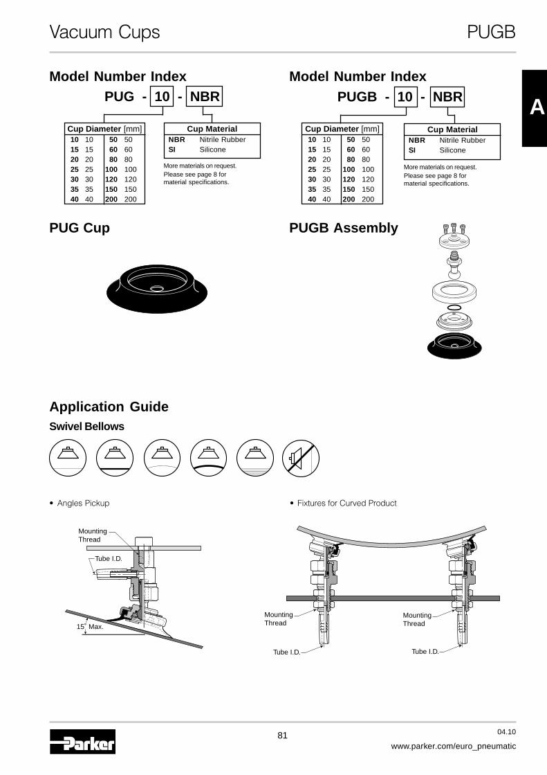
81 04.10
www.parker.com/euro_pneumatic
A
Vacuum Cups PUGB
PUGB - 10 - NBRModel Number Index
Cup MaterialNBR Nitrile RubberSI Silicone
PUG - 10 - NBR
Cup Diameter [mm]10 10 50 5015 15 60 6020 20 80 8025 25 100 10030 30 120 12035 35 150 15040 40 200 200
Model Number Index
Cup MaterialNBR Nitrile RubberSI Silicone
PUGB AssemblyPUG Cup
Cup Diameter [mm]10 10 50 5015 15 60 6020 20 80 8025 25 100 10030 30 120 12035 35 150 15040 40 200 200
More materials on request.Please see page 8 formaterial specifications.
More materials on request.Please see page 8 formaterial specifications.
Application GuideSwivel Bellows
Tube I.D.
Tube I.D.
MountingThread
MountingThread
Tube I.D.
MountingThread15˚ Max.
• Angles Pickup • Fixtures for Curved Product
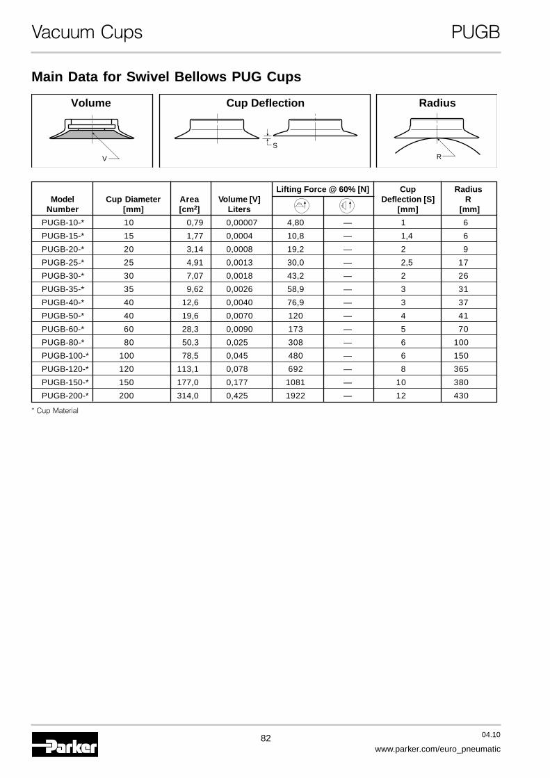
82 04.10
www.parker.com/euro_pneumatic
Vacuum Cups PUGB
Main Data for Swivel Bellows PUG Cups
S
RV
Volume RadiusCup Deflection
Lifting Force @ 60% [N] Cup RadiusModel Cup Diameter Area Volume [V] Deflection [S] R
Number [mm] [cm2] Liters [mm] [mm]
PUGB-10-* 10 0,79 0,00007 4,80 — 1 6
PUGB-15-* 15 1,77 0,0004 10,8 — 1,4 6
PUGB-20-* 20 3,14 0,0008 19,2 — 2 9
PUGB-25-* 25 4,91 0,0013 30,0 — 2,5 17
PUGB-30-* 30 7,07 0,0018 43,2 — 2 26
PUGB-35-* 35 9,62 0,0026 58,9 — 3 31
PUGB-40-* 40 12,6 0,0040 76,9 — 3 37
PUGB-50-* 40 19,6 0,0070 120 — 4 41
PUGB-60-* 60 28,3 0,0090 173 — 5 70
PUGB-80-* 80 50,3 0,025 308 — 6 100
PUGB-100-* 100 78,5 0,045 480 — 6 150
PUGB-120-* 120 113,1 0,078 692 — 8 365
PUGB-150-* 150 177,0 0,177 1081 — 10 380
PUGB-200-* 200 314,0 0,425 1922 — 12 430
* Cup Material
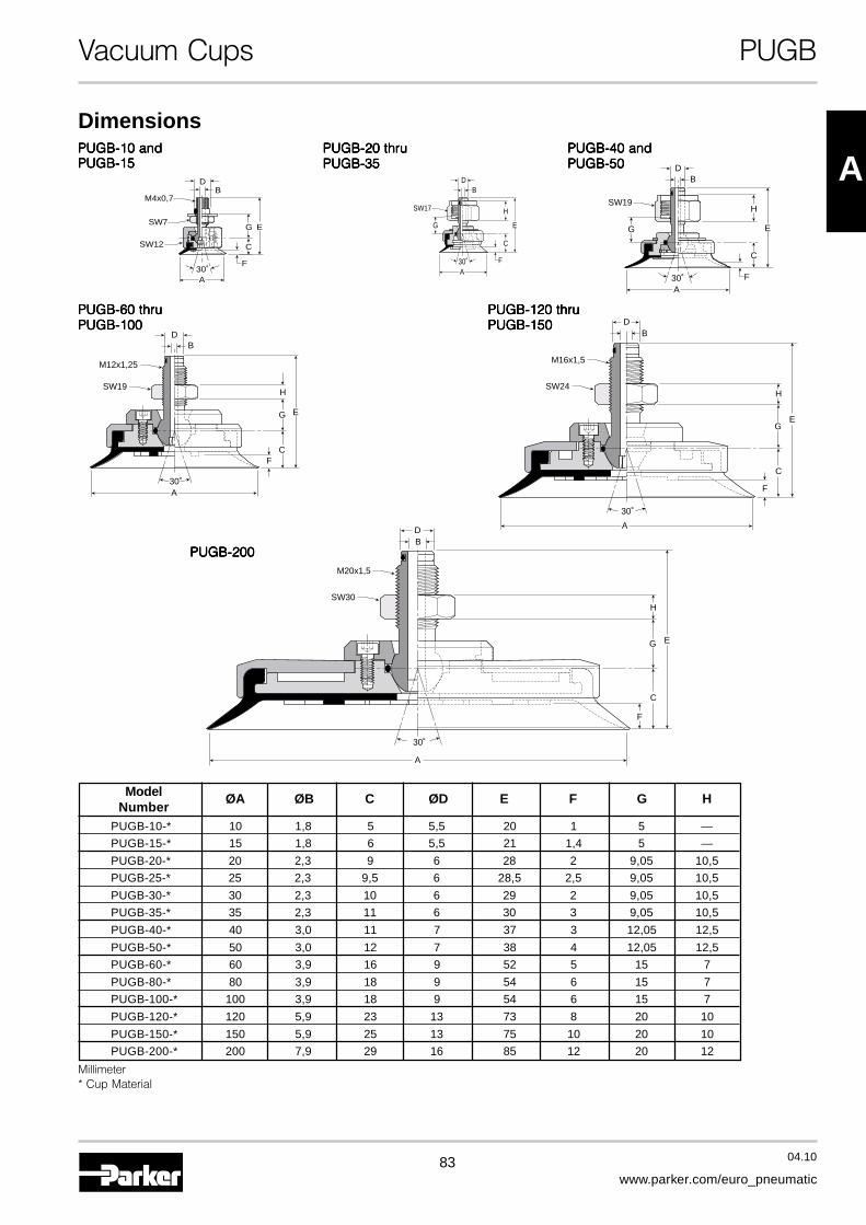
83 04.10
www.parker.com/euro_pneumatic
A
Vacuum Cups PUGB
PUGB-10 andPUGB-10 andPUGB-10 andPUGB-10 andPUGB-10 andPUGB-15PUGB-15PUGB-15PUGB-15PUGB-15
PUGB-20 thruPUGB-20 thruPUGB-20 thruPUGB-20 thruPUGB-20 thruPUGB-35PUGB-35PUGB-35PUGB-35PUGB-35
PUGB-40 andPUGB-40 andPUGB-40 andPUGB-40 andPUGB-40 andPUGB-50PUGB-50PUGB-50PUGB-50PUGB-50
PUGB-60 thruPUGB-60 thruPUGB-60 thruPUGB-60 thruPUGB-60 thruPUGB-100PUGB-100PUGB-100PUGB-100PUGB-100
PUGB-120 thruPUGB-120 thruPUGB-120 thruPUGB-120 thruPUGB-120 thruPUGB-150PUGB-150PUGB-150PUGB-150PUGB-150
PUGB-200PUGB-200PUGB-200PUGB-200PUGB-200
A
M4x0,7
C
E
F
BD
G
30˚
SW7
SW12
A
BD
C
E
F
G
H
30˚
SW17
BD
C
E
F
H
A30˚
SW19
G
BD
E
F
G
C
H
A30˚
SW19
M12x1,25
BD
C
E
F
G
H
A
30˚
SW24
M16x1,5
BD
C
E
F
G
H
A
30˚
SW30
M20x1,5
Dimensions
Model ØA ØB C ØD E F G HNumber
PUGB-10-* 10 1,8 5 5,5 20 1 5 —
PUGB-15-* 15 1,8 6 5,5 21 1,4 5 —
PUGB-20-* 20 2,3 9 6 28 2 9,05 10,5
PUGB-25-* 25 2,3 9,5 6 28,5 2,5 9,05 10,5
PUGB-30-* 30 2,3 10 6 29 2 9,05 10,5
PUGB-35-* 35 2,3 11 6 30 3 9,05 10,5
PUGB-40-* 40 3,0 11 7 37 3 12,05 12,5
PUGB-50-* 50 3,0 12 7 38 4 12,05 12,5
PUGB-60-* 60 3,9 16 9 52 5 15 7
PUGB-80-* 80 3,9 18 9 54 6 15 7
PUGB-100-* 100 3,9 18 9 54 6 15 7
PUGB-120-* 120 5,9 23 13 73 8 20 10
PUGB-150-* 150 5,9 25 13 75 10 20 10
PUGB-200-* 200 7,9 29 16 85 12 20 12
Millimeter* Cup Material

84 04.10
www.parker.com/euro_pneumatic
Vacuum Cup Assemblies PUTK
PUTK Vacuum Cup Assemblies
Installation
Barbed Bulkhead for PUGB Cups
MountingThread
Note:Note:Note:Note:Note:When installing cup assemblies,use a sealant material to securethe assembly and preventvacuum leakage.
Cup MaterialNBR Nitrile
RubberSI Silicone
Model Number IndexPUTK - 10 - NBR
Cup Diameter [mm]10 10 30 3015 15 35 3520 20 40 4025 25 50 50
Millimeter
PUGB Cup Diameter [mm] UTK Fitting Part Number Mounting Thread
10UTK-10 M8x1,25 Male
15
2025
UTK-20 M10x1,5 Male303540
UTK-40 M14x1,5 Male50
6080 UTYK-60-G1 M16x1,5 Male
100120150
UTYK-120-G1 M22x1,5 Male
200 UTYK-200-G2 M22x1,5 Male
More materials on request.Please see page 8 formaterial specifications.
PUTYK - 60 - NBR - G1
Cup Diameter [mm]60 60 120 12080 80 150 150
100 100 200 200
Vacuum PortG1 1/8 BSPPG2 1/4 BSPPSee Chart
Below
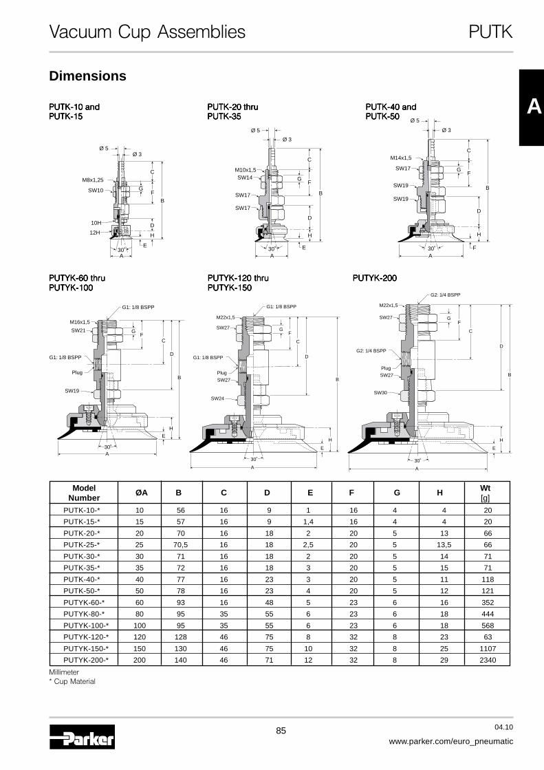
85 04.10
www.parker.com/euro_pneumatic
A
Vacuum Cup Assemblies PUTK
PUTK-10 andPUTK-10 andPUTK-10 andPUTK-10 andPUTK-10 andPUTK-15PUTK-15PUTK-15PUTK-15PUTK-15
PUTK-40 andPUTK-40 andPUTK-40 andPUTK-40 andPUTK-40 andPUTK-50PUTK-50PUTK-50PUTK-50PUTK-50
PUTYK-60 thruPUTYK-60 thruPUTYK-60 thruPUTYK-60 thruPUTYK-60 thruPUTYK-100PUTYK-100PUTYK-100PUTYK-100PUTYK-100
Dimensions
PUTK-20 thruPUTK-20 thruPUTK-20 thruPUTK-20 thruPUTK-20 thruPUTK-35PUTK-35PUTK-35PUTK-35PUTK-35
A
H
E
D
30˚
10H
12H
B
G
C
F
M8x1,25
SW10
Ø 5Ø 3
A
H
E
G
D
30˚
B
C
F
M10x1,5SW14
SW17
SW17
Ø 5
Ø 3
G
C
F
M14x1,5
SW17
SW19
SW19
H
B
F
D
A30˚
Ø 5
Ø 3
B
EH
A30˚
SW19
G1: 1/8 BSPP
G1: 1/8 BSPP
SW21
M16x1,5
FG
D
C
Plug
PUTYK-120 thruPUTYK-120 thruPUTYK-120 thruPUTYK-120 thruPUTYK-120 thruPUTYK-150PUTYK-150PUTYK-150PUTYK-150PUTYK-150
PUTYK-200PUTYK-200PUTYK-200PUTYK-200PUTYK-200
H
E
A
30˚
SW24
B
G1: 1/8 BSPP
G1: 1/8 BSPP
SW27
SW27
M22x1,5
FG
D
C
Plug
H
E
A
30˚
SW30
B
G2: 1/4 BSPP
G2: 1/4 BSPP
SW27
SW27
M22x1,5
FG
D
C
Plug
Model ØA B C D E F G H WtNumber [g]
PUTK-10-* 10 56 16 9 1 16 4 4 20
PUTK-15-* 15 57 16 9 1,4 16 4 4 20
PUTK-20-* 20 70 16 18 2 20 5 13 66
PUTK-25-* 25 70,5 16 18 2,5 20 5 13,5 66
PUTK-30-* 30 71 16 18 2 20 5 14 71
PUTK-35-* 35 72 16 18 3 20 5 15 71
PUTK-40-* 40 77 16 23 3 20 5 11 118
PUTK-50-* 50 78 16 23 4 20 5 12 121
PUTYK-60-* 60 93 16 48 5 23 6 16 352
PUTYK-80-* 80 95 35 55 6 23 6 18 444
PUTYK-100-* 100 95 35 55 6 23 6 18 568
PUTYK-120-* 120 128 46 75 8 32 8 23 63
PUTYK-150-* 150 130 46 75 10 32 8 25 1107
PUTYK-200-* 200 140 46 71 12 32 8 29 2340
Millimeter* Cup Material

86 04.10
www.parker.com/euro_pneumatic
Vacuum Cup Assemblies PUYK
90° Barbed Adapter for PUGB Cups
PUYK Vacuum Cup Assemblies
Installation MountingThread
Note:Note:Note:Note:Note:When installing cup assemblies,use a sealant material to securethe assembly and preventvacuum leakage.
PUGB Cup Diameter [mm] UYK Fitting Part Number Mounting Thread10
UYK-10 M4x0,7 Female15
2025
UYK-20 M6x1 Female303540
UYK-40 M8x1,25 Female50
6080 UTYK-60-G1 M16x1,5 Male
100120150 UTYK-120-G1 M22x1,5 Male
200 UTYK-200-G2 M22x1,5 Male
Millimeter
Model Number IndexPUYK - 10 - NBR
Cup MaterialNBR Nitrile
RubberSI Silicone
Vacuum PortBlank Barb
G1 1/8 BSPPG2 1/4 BSPPSee Chart
Below
Cup Diameter [mm]10 10 30 3015 15 35 3520 20 40 4025 25 50 50 More materials on request.
Please see page 8 formaterial specifications.
PUTYK - 60 - NBR - G1
Cup Diameter [mm]60 60 120 12080 80 150 150
100 100 200 200
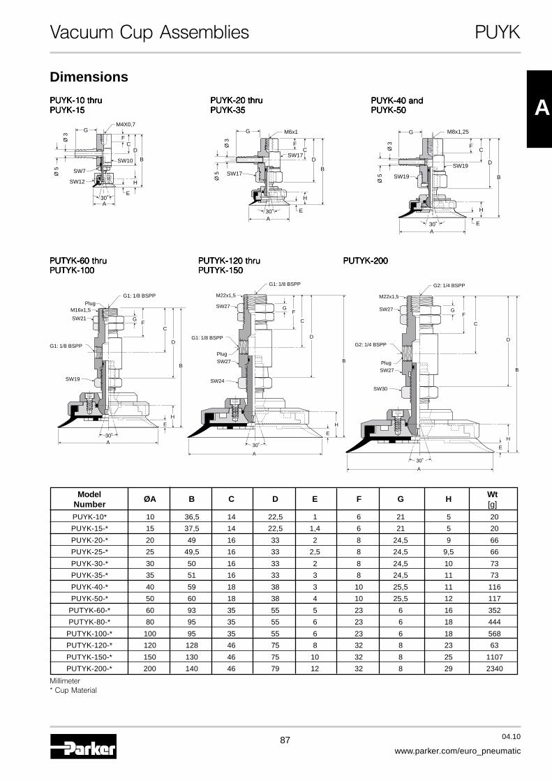
87 04.10
www.parker.com/euro_pneumatic
A
H
E
A
30˚
SW24
B
G1: 1/8 BSPP
G1: 1/8 BSPP
SW27
SW27
M22x1,5
FG
D
C
Plug
Vacuum Cup Assemblies PUYK
PUYK-10 thruPUYK-10 thruPUYK-10 thruPUYK-10 thruPUYK-10 thruPUYK-15PUYK-15PUYK-15PUYK-15PUYK-15
A
H
E30˚
SW10
SW12
SW7
FC
D
B
Ø 5
Ø 3
M4X0,7G
CF
M8x1,25
SW19
SW19
H
B
E
D
A30˚
Ø 5
Ø 3
G
PUYK-40 andPUYK-40 andPUYK-40 andPUYK-40 andPUYK-40 andPUYK-50PUYK-50PUYK-50PUYK-50PUYK-50
PUTYK-60 thruPUTYK-60 thruPUTYK-60 thruPUTYK-60 thruPUTYK-60 thruPUTYK-100PUTYK-100PUTYK-100PUTYK-100PUTYK-100
Dimensions
PUYK-20 thruPUYK-20 thruPUYK-20 thruPUYK-20 thruPUYK-20 thruPUYK-35PUYK-35PUYK-35PUYK-35PUYK-35
PUTYK-200PUTYK-200PUTYK-200PUTYK-200PUTYK-200
AE30˚
SW17
CF
M6x1
SW17
H
B
D
Ø 5
Ø 3
G
B
EH
A30˚
SW19
G1: 1/8 BSPP
G1: 1/8 BSPP
SW21
M16x1,5Plug
FG
D
C
H
E
A
30˚
SW30
B
G2: 1/4 BSPP
G2: 1/4 BSPP
SW27
SW27
M22x1,5
FG
D
C
Plug
PUTYK-120 thruPUTYK-120 thruPUTYK-120 thruPUTYK-120 thruPUTYK-120 thruPUTYK-150PUTYK-150PUTYK-150PUTYK-150PUTYK-150
Model ØA B C D E F G H WtNumber [g]
PUYK-10* 10 36,5 14 22,5 1 6 21 5 20
PUYK-15-* 15 37,5 14 22,5 1,4 6 21 5 20
PUYK-20-* 20 49 16 33 2 8 24,5 9 66
PUYK-25-* 25 49,5 16 33 2,5 8 24,5 9,5 66
PUYK-30-* 30 50 16 33 2 8 24,5 10 73
PUYK-35-* 35 51 16 33 3 8 24,5 11 73
PUYK-40-* 40 59 18 38 3 10 25,5 11 116
PUYK-50-* 50 60 18 38 4 10 25,5 12 117
PUTYK-60-* 60 93 35 55 5 23 6 16 352
PUTYK-80-* 80 95 35 55 6 23 6 18 444
PUTYK-100-* 100 95 35 55 6 23 6 18 568
PUTYK-120-* 120 128 46 75 8 32 8 23 63
PUTYK-150-* 150 130 46 75 10 32 8 25 1107
PUTYK-200-* 200 140 46 79 12 32 8 29 2340
Millimeter* Cup Material
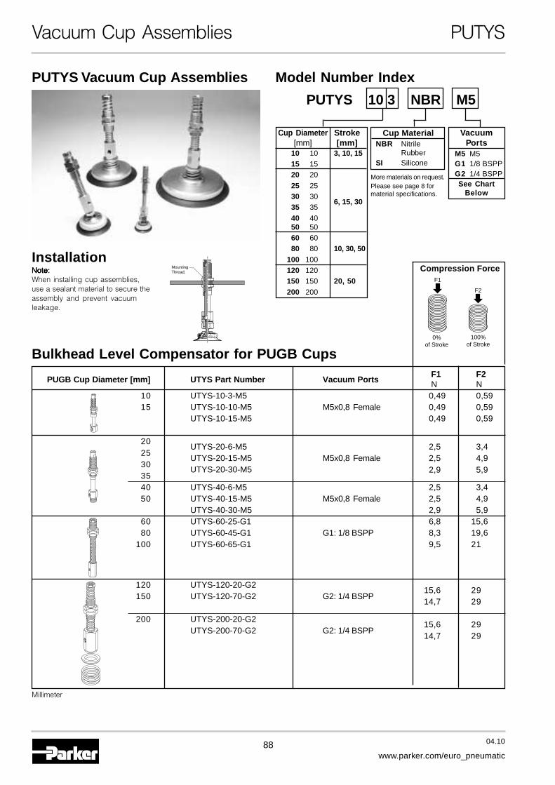
88 04.10
www.parker.com/euro_pneumatic
Vacuum Cup Assemblies PUTYS
Bulkhead Level Compensator for PUGB Cups
PUTYS Vacuum Cup Assemblies
InstallationNote:Note:Note:Note:Note:When installing cup assemblies,use a sealant material to secure theassembly and prevent vacuumleakage.
MountingThread.
Cup Diameter Stroke[mm] [mm]
10 10 3, 10, 1515 1520 20
25 2530 30
6, 15, 3035 35
40 4050 5060 6080 80 10, 30, 50
100 100120 120150 150 20, 50200 200
Model Number Index
Cup MaterialNBR Nitrile
RubberSI Silicone
PUTYS 10 3 NBR M5
VacuumPorts
M5 M5G1 1/8 BSPPG2 1/4 BSPPSee Chart
Below
Compression ForceF1
0%of Stroke
100%of Stroke
F2
Millimeter
PUGB Cup Diameter [mm] UTYS Part Number Vacuum PortsF1 F2N N
10 UTYS-10-3-M5 0,49 0,5915 UTYS-10-10-M5 M5x0,8 Female 0,49 0,59
UTYS-10-15-M5 0,49 0,59
20UTYS-20-6-M5 2,5 3,4
25UTYS-20-15-M5 M5x0,8 Female 2,5 4,9
30UTYS-20-30-M5 2,9 5,9
3540 UTYS-40-6-M5 2,5 3,450 UTYS-40-15-M5 M5x0,8 Female 2,5 4,9
UTYS-40-30-M5 2,9 5,960 UTYS-60-25-G1 6,8 15,680 UTYS-60-45-G1 G1: 1/8 BSPP 8,3 19,6
100 UTYS-60-65-G1 9,5 21
120 UTYS-120-20-G215,6 29
150 UTYS-120-70-G2 G2: 1/4 BSPP14,7 29
200 UTYS-200-20-G215,6 29
UTYS-200-70-G2 G2: 1/4 BSPP14,7 29
More materials on request.Please see page 8 formaterial specifications.

89 04.10
www.parker.com/euro_pneumatic
A
Vacuum Cup Assemblies PUTYS
PUTYS406 thruPUTYS406 thruPUTYS406 thruPUTYS406 thruPUTYS406 thru
PUTYS5030PUTYS5030PUTYS5030PUTYS5030PUTYS5030PUTYS103 thruPUTYS103 thruPUTYS103 thruPUTYS103 thruPUTYS103 thru
PUTYS1515PUTYS1515PUTYS1515PUTYS1515PUTYS1515
Dimensions
B
EA
SW17
M5x0,8 SW12
SW19
SW17
M14x1
M5x0,8D
C
H
5
F
G
A
SW7
SW12
M5x0,8
M5x0,8
SW6
SW12
M8x0,75
B
D
C
F
9
H
G
E
PUTYS206 thruPUTYS206 thruPUTYS206 thruPUTYS206 thruPUTYS206 thru
PUTYS3530PUTYS3530PUTYS3530PUTYS3530PUTYS3530
B
EA
SW17
M5x0,8 SW12
SW19
SW17
M14x1
M5x0,8D
C
H
5
F
G
Model ØA B C D E F G H WtNumber [g]
PUTYS103* 10 67,5 18,5 8 1 3 3 23 25
PUTYS1010* 10 74,5 18,5 8 1 10 3 23 26
PUTYS1015* 10 87 18,5 8 1 15 3 30,5 28
PUTYS153* 15 68,5 18,5 8 1,4 3 3 23 25
PUTYS1510* 15 75,5 18,5 8 1,4 10 3 23 26
PUTYS1515* 15 88 18,5 8 1,4 15 3 30,5 28
PUTYS206* 20 89,5 16 10 2 6 5 36 89
PUTYS2015* 20 98,5 16 10 2 15 5 36 94
PUTYS2030* 20 135,5 16 10 2 30 5 58 119
PUTYS256* 20 90 16 10 2,5 6 5 36 89
PUTYS2515* 20 99 16 10 2,5 15 5 36 94
PUTYS2530* 20 136 16 10 2,5 30 5 58 119
PUTYS306* 30 90,5 16 10 2 6 5 36 94
PUTYS3015* 30 99,5 16 10 2 15 5 36 99
PUTYS3030* 30 136,5 16 10 2 30 5 58 124
PUTYS356* 30 91,5 16 10 3 6 5 36 94
PUTYS3515* 30 100,5 16 10 3 15 5 36 99
PUTYS3530* 30 137,5 16 10 3 30 5 58 124
PUTYS406* 40 97,5 17 10 3 6 5 36 123
PUTYS4015* 40 106,5 17 10 3 15 5 36 128
PUTYS4030* 40 143,5 17 10 3 30 5 58 153
PUTYS506* 50 98,5 17 10 4 6 5 36 123
PUTYS5015* 50 107,5 17 10 4 15 5 36 128
PUTYS5030* 50 144,5 17 10 4 30 5 58 154
Millimeter* Cup Material
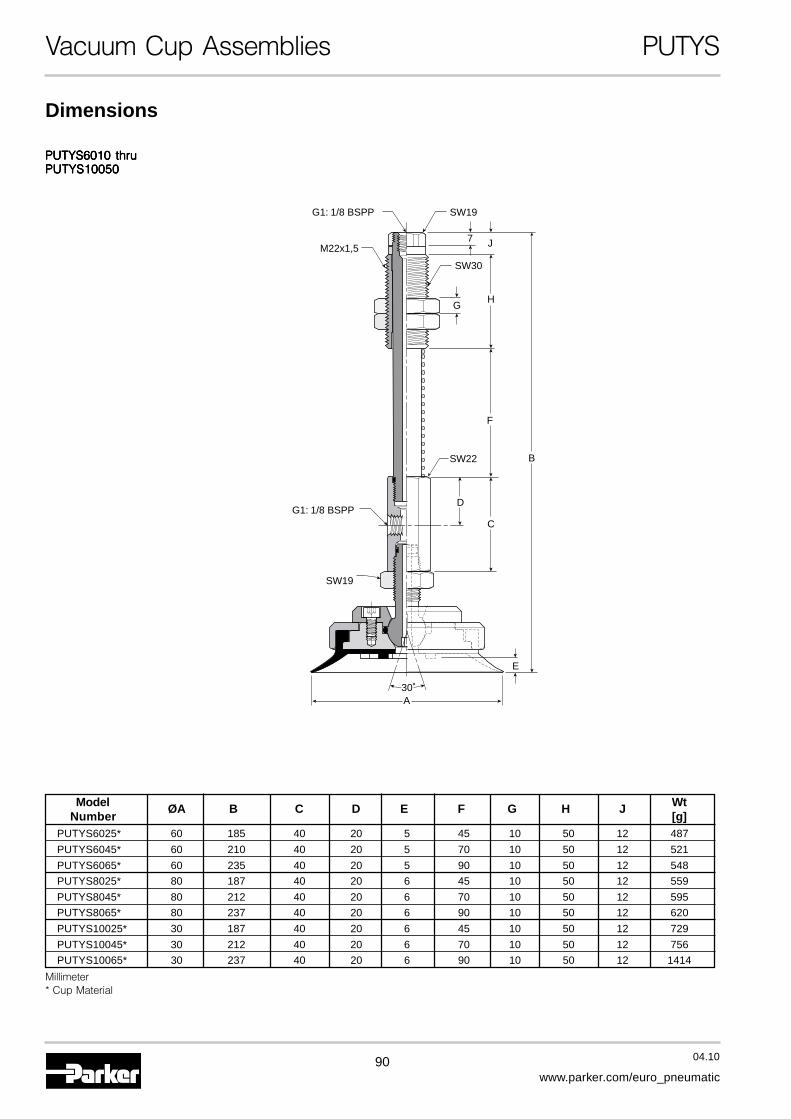
90 04.10
www.parker.com/euro_pneumatic
Vacuum Cup Assemblies PUTYS
PUTYS6010 thruPUTYS6010 thruPUTYS6010 thruPUTYS6010 thruPUTYS6010 thruPUTYS10050PUTYS10050PUTYS10050PUTYS10050PUTYS10050
Dimensions
E
A30˚
SW19
G1: 1/8 BSPP
G1: 1/8 BSPP
SW19
SW30
M22x1,5
B
D
C
H
J7
F
G
SW22
Model ØA B C D E F G H J WtNumber [g]
PUTYS6025* 60 185 40 20 5 45 10 50 12 487
PUTYS6045* 60 210 40 20 5 70 10 50 12 521
PUTYS6065* 60 235 40 20 5 90 10 50 12 548
PUTYS8025* 80 187 40 20 6 45 10 50 12 559
PUTYS8045* 80 212 40 20 6 70 10 50 12 595
PUTYS8065* 80 237 40 20 6 90 10 50 12 620
PUTYS10025* 30 187 40 20 6 45 10 50 12 729
PUTYS10045* 30 212 40 20 6 70 10 50 12 756
PUTYS10065* 30 237 40 20 6 90 10 50 12 1414
Millimeter* Cup Material
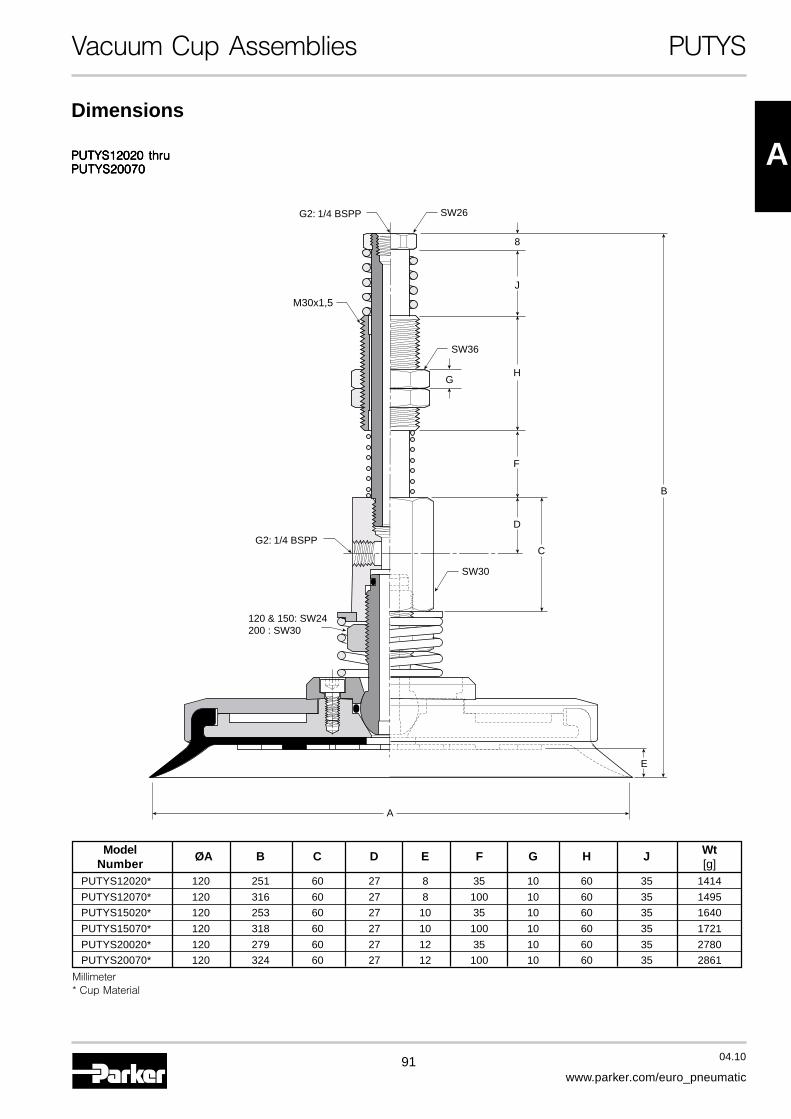
91 04.10
www.parker.com/euro_pneumatic
A
Vacuum Cup Assemblies PUTYS
PUTYS12020 thruPUTYS12020 thruPUTYS12020 thruPUTYS12020 thruPUTYS12020 thruPUTYS20070PUTYS20070PUTYS20070PUTYS20070PUTYS20070
Dimensions
E
A
120 & 150: SW24200 : SW30
SW26
SW36
SW30
M30x1,5
B
J
8
F
D
HG
C
G2: 1/4 BSPP
G2: 1/4 BSPP
Model ØA B C D E F G H J WtNumber [g]
PUTYS12020* 120 251 60 27 8 35 10 60 35 1414
PUTYS12070* 120 316 60 27 8 100 10 60 35 1495
PUTYS15020* 120 253 60 27 10 35 10 60 35 1640
PUTYS15070* 120 318 60 27 10 100 10 60 35 1721
PUTYS20020* 120 279 60 27 12 35 10 60 35 2780
PUTYS20070* 120 324 60 27 12 100 10 60 35 2861
Millimeter* Cup Material

92 04.10
www.parker.com/euro_pneumatic
Vacuum Cups PFOG
PFOG GroovedVacuum Cups
Features
• Vacuum Grooves On UndersideIncreases Holding Area
• Resists Acceleration andDeceleration Shear
• Shear Resistance Is Increased By 25%
• 20 mm to 40 mm Diameters
ApplicationsThe anti-slip flat cups are for pick-and- place applications thatrequire an increased holding force without having to increasethe diameter of the cup. The grooved foot pattern channelsthe vacuum flow to the cup’s outer diameter which increasesresistance to the shear force by 25% over conventional flatpads. These cups are perfect for high speed press transfer ofsmall to medium sized stamped metal products with oilysurfaces. This cup also works well with corrugated product.
PFOTK SeriesBarbed BulkheadTop stem connectors secured with jam nutsand allow tubing connections at the topside. Nickel plated brass materials.
PFOYK Series90° Barbed AdapterSide stem connectors allow you to securethe stem with a bolt through a plate or “L”bracket to allow the tube connection fromthe side port. Nickel plated brass materials.
PFOTYS Series BulkheadLevel Compensator303 stainless steel construction secured withjam nuts. Spring biased compensators canabsorb impacts of down-strokes and adjust fordifferent levels of pick up points. 303 stainlesscorrosion resistant materials with drymetbushings increases the strength and life.
PFOG Series Vacuum CupsSpecial grooved flat cup with single lip provides increasesvacuum flow area. Increased holding force resists againstslipping of products with oily surfaces. Increased holdingforce also works well with corrugated product.
PFOTM Series Male ThreadConnectorSimple male connection for low profilepositions secured to a plate or bracket.
Fitting Material: Aluminium.
PFOTF Series FemaleThread ConnectorSimple female connection for low profilepositions secured to a plate or bracket.
Fitting Material: Aluminium.
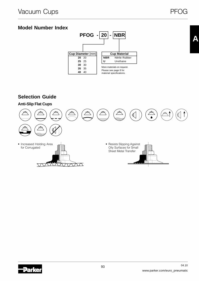
93 04.10
www.parker.com/euro_pneumatic
A
Vacuum Cups PFOG
PFOG - 20 - NBR
Cup Diameter [mm]20 2025 2530 3035 3540 40
Model Number Index
Cup MaterialNBR Nitrile RubberU Urethane
Selection GuideAnti-Slip Flat Cups
• Increased Holding Areafor Corrugated
• Resists Slipping AgainstOily Surfaces for SmallSheet Metal Transfer
More materials on request.Please see page 8 formaterial specifications.

94 04.10
www.parker.com/euro_pneumatic
Vacuum Cups PFOG
PFOG-20PFOG-20PFOG-20PFOG-20PFOG-20 PFOG-25 thruPFOG-25 thruPFOG-25 thruPFOG-25 thruPFOG-25 thruPFOG-40PFOG-40PFOG-40PFOG-40PFOG-40
Main Data for Anti-Slip PFOG Suction Cups
SRV
Volume RadiusCup Deflection
C F
E
B
H
D
AC F
E
B
H
D
A
Dimensions
Model ØA ØB ØC ØD E F HNumber
PFOG-20-* 20 4,6 11 15 10 1,5 4,5
PFOG-25-* 25 6 11 16 14 1,1 7
PFOG-30-* 30 6 11 14 12 1,3 7
PFOG-35-* 35 6 11 21 12 1,6 7
PFOG-40-* 40 6 11 24 14 2,8 7
Millimeter* Cup Material
Lifting Force @ 60% [N] Cup RadiusModel Cup Diameter Area Volume [V] Deflection [S] R
Number [mm] [cm2] liters [mm] [mm]PFOG-20 20 3,14 0,0008 18,0 11,25 2,3 4,0PFOG-25 25 4,91 0,0013 29,0 18,0 3,0 17,5PFOG-30 30 7,07 0,0018 42,0 26,0 2,0 26,0PFOG-35 35 9,62 0,0026 57,0 35,0 3,0 37,0PFOG-40 40 12,60 0,0040 74,0 46,0 3,5 41,0
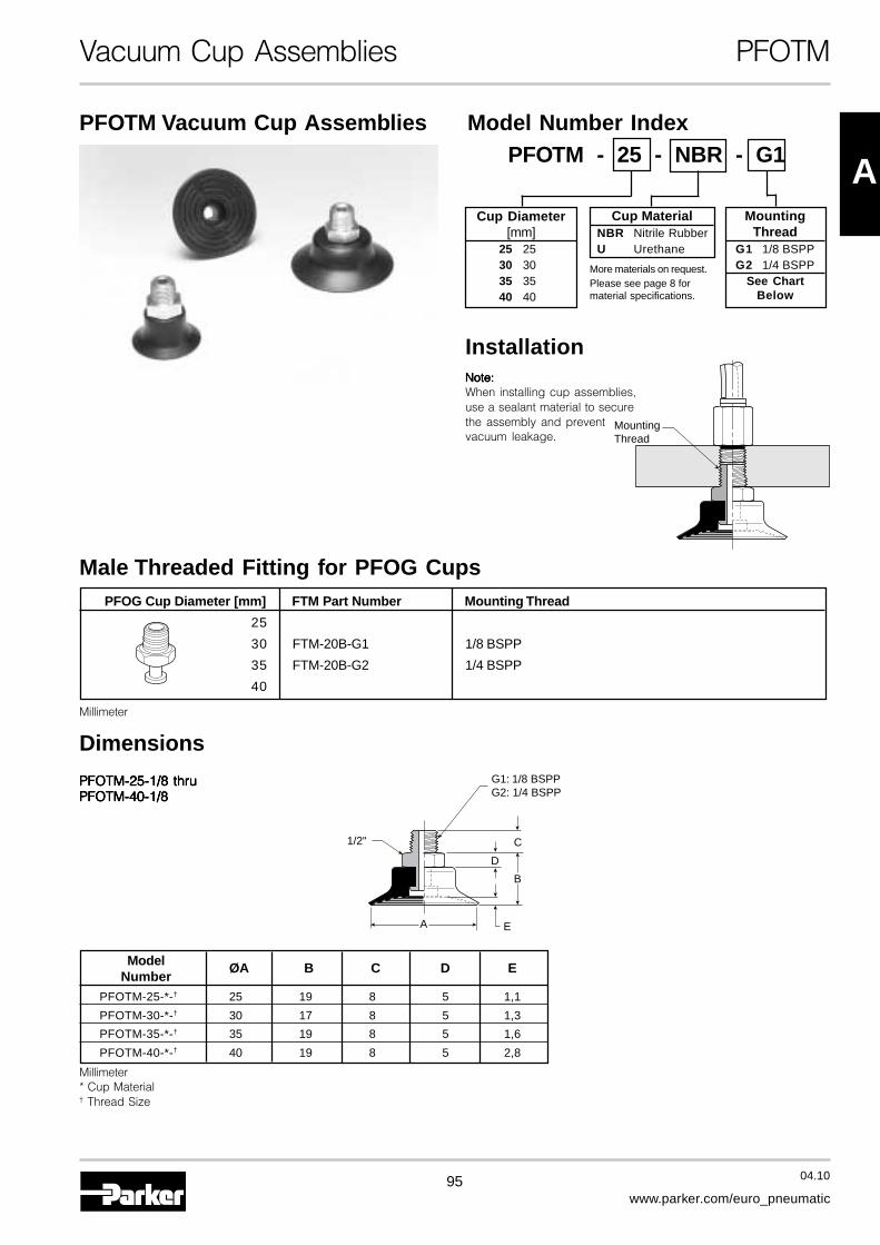
95 04.10
www.parker.com/euro_pneumatic
A
Vacuum Cup Assemblies PFOTM
Male Threaded Fitting for PFOG Cups
PFOTM Vacuum Cup Assemblies
MountingThread
Installation
PFOTM-25-1/8 thruPFOTM-25-1/8 thruPFOTM-25-1/8 thruPFOTM-25-1/8 thruPFOTM-25-1/8 thruPFOTM-40-1/8PFOTM-40-1/8PFOTM-40-1/8PFOTM-40-1/8PFOTM-40-1/8
B
A E
D
C
G1: 1/8 BSPPG2: 1/4 BSPP
1/2"
Dimensions
Note:Note:Note:Note:Note:When installing cup assemblies,use a sealant material to securethe assembly and preventvacuum leakage.
Millimeter
Model ØA B C D ENumber
PFOTM-25-*-† 25 19 8 5 1,1
PFOTM-30-*-† 30 17 8 5 1,3
PFOTM-35-*-† 35 19 8 5 1,6
PFOTM-40-*-† 40 19 8 5 2,8
Millimeter* Cup Material† Thread Size
PFOG Cup Diameter [mm] FTM Part Number Mounting Thread
25
30 FTM-20B-G1 1/8 BSPP
35 FTM-20B-G2 1/4 BSPP
40
Cup Diameter[mm]
25 2530 3035 3540 40
Cup MaterialNBR Nitrile RubberU Urethane
Model Number IndexPFOTM - 25 - NBR - G1
MountingThread
G1 1/8 BSPPG2 1/4 BSPP
See ChartBelow
More materials on request.Please see page 8 formaterial specifications.
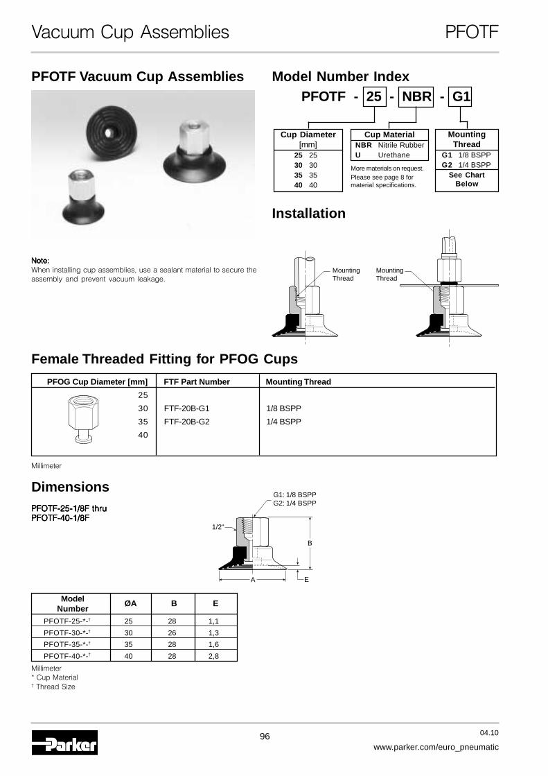
96 04.10
www.parker.com/euro_pneumatic
Vacuum Cup Assemblies PFOTF
Female Threaded Fitting for PFOG Cups
PFOTF Vacuum Cup Assemblies
MountingThread
MountingThread
Installation
PFOTF-25-1/8F thruPFOTF-25-1/8F thruPFOTF-25-1/8F thruPFOTF-25-1/8F thruPFOTF-25-1/8F thruPFOTF-40-1/8FPFOTF-40-1/8FPFOTF-40-1/8FPFOTF-40-1/8FPFOTF-40-1/8F
G1: 1/8 BSPPG2: 1/4 BSPP
1/2"
B
EA
Dimensions
Note:Note:Note:Note:Note:When installing cup assemblies, use a sealant material to secure theassembly and prevent vacuum leakage.
Millimeter
Model ØA B ENumber
PFOTF-25-*-† 25 28 1,1
PFOTF-30-*-† 30 26 1,3
PFOTF-35-*-† 35 28 1,6
PFOTF-40-*-† 40 28 2,8
Millimeter* Cup Material† Thread Size
PFOG Cup Diameter [mm] FTF Part Number Mounting Thread
25
30 FTF-20B-G1 1/8 BSPP
35 FTF-20B-G2 1/4 BSPP
40
Model Number IndexPFOTF - 25 - NBR - G1
MountingThread
G1 1/8 BSPPG2 1/4 BSPP
See ChartBelow
Cup Diameter[mm]
25 2530 3035 3540 40
Cup MaterialNBR Nitrile RubberU Urethane
More materials on request.Please see page 8 formaterial specifications.
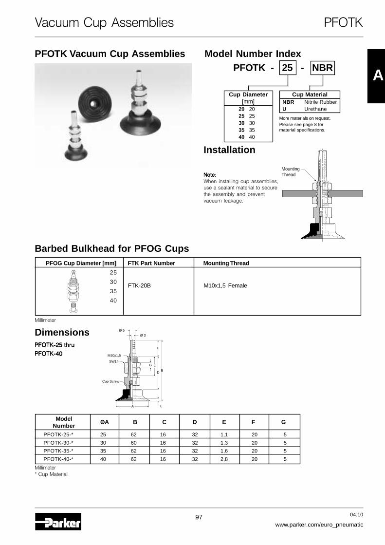
97 04.10
www.parker.com/euro_pneumatic
A
Vacuum Cup Assemblies PFOTK
Barbed Bulkhead for PFOG Cups
PFOTK Vacuum Cup Assemblies
MountingThread
Installation
BFG
C
D
E
M10x1,5
Cup Screw
SW14
Ø 5Ø 3
A
Dimensions
Note:Note:Note:Note:Note:When installing cup assemblies,use a sealant material to securethe assembly and preventvacuum leakage.
PFOTK-25 thruPFOTK-25 thruPFOTK-25 thruPFOTK-25 thruPFOTK-25 thru
PFOTK-40PFOTK-40PFOTK-40PFOTK-40PFOTK-40
Model ØA B C D E F GNumber
PFOTK-25-* 25 62 16 32 1,1 20 5
PFOTK-30-* 30 60 16 32 1,3 20 5
PFOTK-35-* 35 62 16 32 1,6 20 5
PFOTK-40-* 40 62 16 32 2,8 20 5
Millimeter* Cup Material
PFOG Cup Diameter [mm] FTK Part Number Mounting Thread
25
30FTK-20B M10x1,5 Female
35
40
Millimeter
Cup MaterialNBR Nitrile RubberU Urethane
Model Number IndexPFOTK - 25 - NBR
Cup Diameter[mm]
20 2025 2530 3035 3540 40
More materials on request.Please see page 8 formaterial specifications.
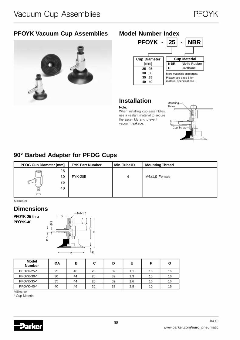
98 04.10
www.parker.com/euro_pneumatic
Vacuum Cup Assemblies PFOYK
90° Barbed Adapter for PFOG Cups
PFOYK Vacuum Cup Assemblies
Cup Screw
MountingThread
Installation
Cup MaterialNBR Nitrile RubberU Urethane
Model Number IndexPFOYK - 25 - NBR
B
F
GM6x1,0
C
D
E
Ø 5
Ø 3
A
Dimensions
Note:Note:Note:Note:Note:When installing cup assemblies,use a sealant material to securethe assembly and preventvacuum leakage.
PFOYK-25 thruPFOYK-25 thruPFOYK-25 thruPFOYK-25 thruPFOYK-25 thru
PFOYK-40PFOYK-40PFOYK-40PFOYK-40PFOYK-40
Cup Diameter[mm]
25 2530 3035 3540 40
Model ØA B C D E F GNumber
PFOYK-25-* 25 46 20 32 1,1 10 16
PFOYK-30-* 30 44 20 32 1,3 10 16
PFOYK-35-* 35 44 20 32 1,6 10 16
PFOYK-40-* 40 46 20 32 2,8 10 16
Millimeter* Cup Material
PFOG Cup Diameter [mm] FYK Part Number Min. Tube ID Mounting Thread
25
30 FYK-20B 4 M6x1,0 Female
35
40
Millimeter
More materials on request.Please see page 8 formaterial specifications.
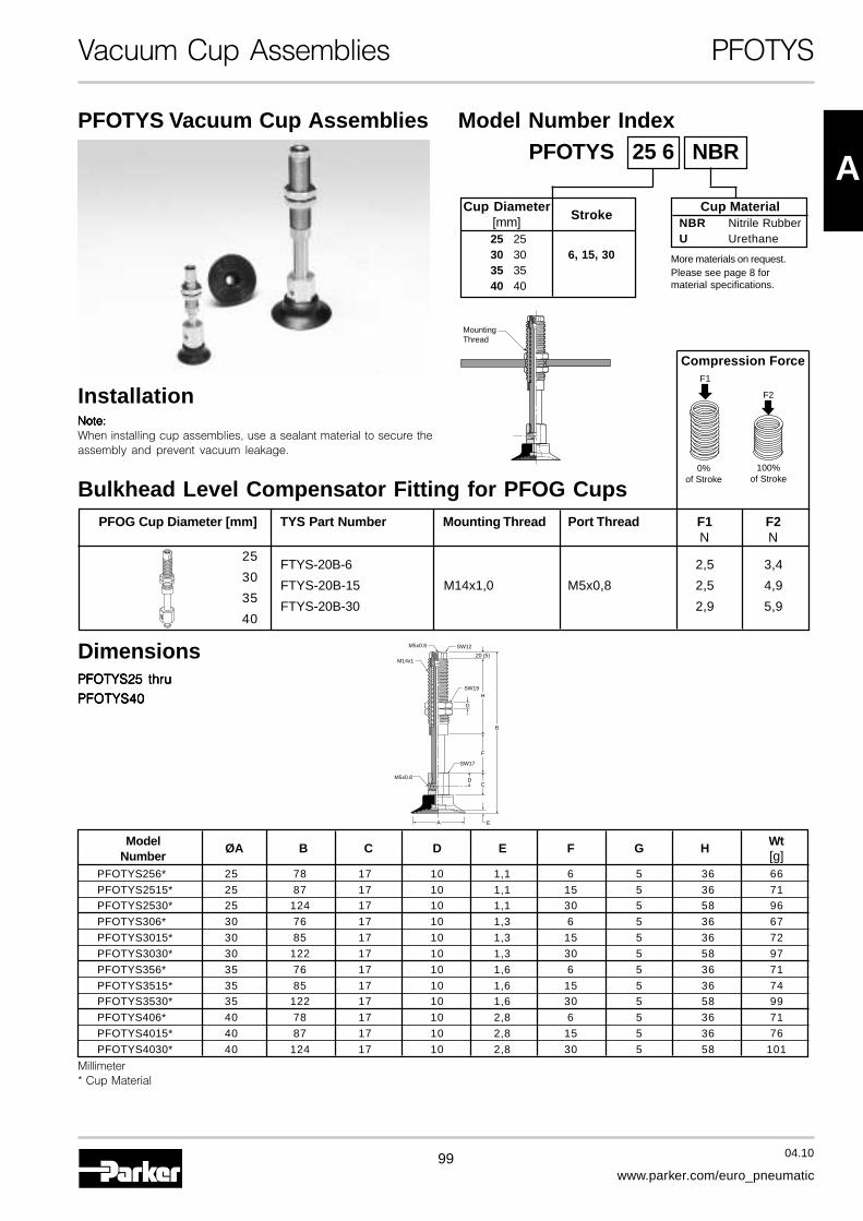
99 04.10
www.parker.com/euro_pneumatic
A
Vacuum Cup Assemblies PFOTYS
Bulkhead Level Compensator Fitting for PFOG Cups
PFOTYS Vacuum Cup Assemblies
MountingThread
Installation
PFOTYS25 thruPFOTYS25 thruPFOTYS25 thruPFOTYS25 thruPFOTYS25 thru
PFOTYS40PFOTYS40PFOTYS40PFOTYS40PFOTYS40
M5x0.8
M5x0.8
SW12
SW19
SW17
M14x1
B
D
E
C
H
.20 (5)
F
G
A
Dimensions
Note:Note:Note:Note:Note:When installing cup assemblies, use a sealant material to secure theassembly and prevent vacuum leakage.
Cup DiameterStroke[mm]
25 2530 30 6, 15, 3035 3540 40
Cup MaterialNBR Nitrile RubberU Urethane
Model Number IndexPFOTYS 25 6 NBR
Model ØA B C D E F G H WtNumber [g]
PFOTYS256* 25 78 17 10 1,1 6 5 36 66
PFOTYS2515* 25 87 17 10 1,1 15 5 36 71PFOTYS2530* 25 124 17 10 1,1 30 5 58 96
PFOTYS306* 30 76 17 10 1,3 6 5 36 67
PFOTYS3015* 30 85 17 10 1,3 15 5 36 72
PFOTYS3030* 30 122 17 10 1,3 30 5 58 97
PFOTYS356* 35 76 17 10 1,6 6 5 36 71
PFOTYS3515* 35 85 17 10 1,6 15 5 36 74PFOTYS3530* 35 122 17 10 1,6 30 5 58 99
PFOTYS406* 40 78 17 10 2,8 6 5 36 71
PFOTYS4015* 40 87 17 10 2,8 15 5 36 76
PFOTYS4030* 40 124 17 10 2,8 30 5 58 101
Millimeter* Cup Material
Compression ForceF1
0%of Stroke
100%of Stroke
F2
PFOG Cup Diameter [mm] TYS Part Number Mounting Thread Port Thread F1 F2N N
25FTYS-20B-6 2,5 3,4
30FTYS-20B-15 M14x1,0 M5x0,8 2,5 4,9
35FTYS-20B-30 2,9 5,9
40
More materials on request.Please see page 8 formaterial specifications.
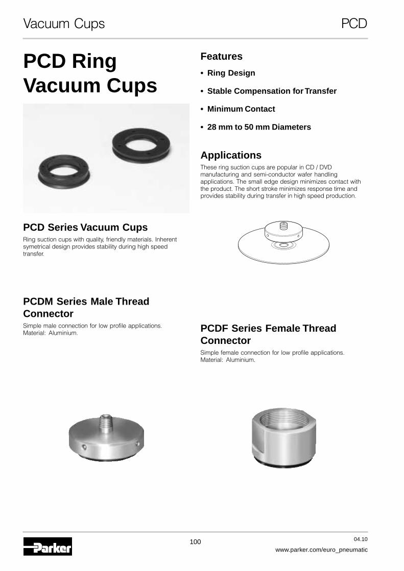
100 04.10
www.parker.com/euro_pneumatic
Vacuum Cups PCD
PCD RingVacuum Cups
Features
• Ring Design
• Stable Compensation for Transfer
• Minimum Contact
• 28 mm to 50 mm Diameters
ApplicationsThese ring suction cups are popular in CD / DVDmanufacturing and semi-conductor wafer handlingapplications. The small edge design minimizes contact withthe product. The short stroke minimizes response time andprovides stability during transfer in high speed production.
PCD Series Vacuum CupsRing suction cups with quality, friendly materials. Inherentsymetrical design provides stability during high speedtransfer.
PCDM Series Male ThreadConnectorSimple male connection for low profile applications.Material: Aluminium. PCDF Series Female Thread
ConnectorSimple female connection for low profile applications.Material: Aluminium.

101 04.10
www.parker.com/euro_pneumatic
A
Vacuum Cups PCD
B
D
A
C
PCD - 23 - NBR
Model Number Index
Cup MaterialSI Silicone
Cup I.D. [mm]20 2023 23
29.5 29,534 3438 3846 46
DimensionsModel ØA B C D
NumberPCD20* 20 33 6,5 2
PCD23* 23 37 5 3
PCD29,5* 29,5 43,5 5 3
PCD34* 34 48 7 2
PCD38* 38 52 5 3
PCD46* 46 58 7 2
Millimeter* Cup Material
More materials on request.Please see page 8 formaterial specifications.
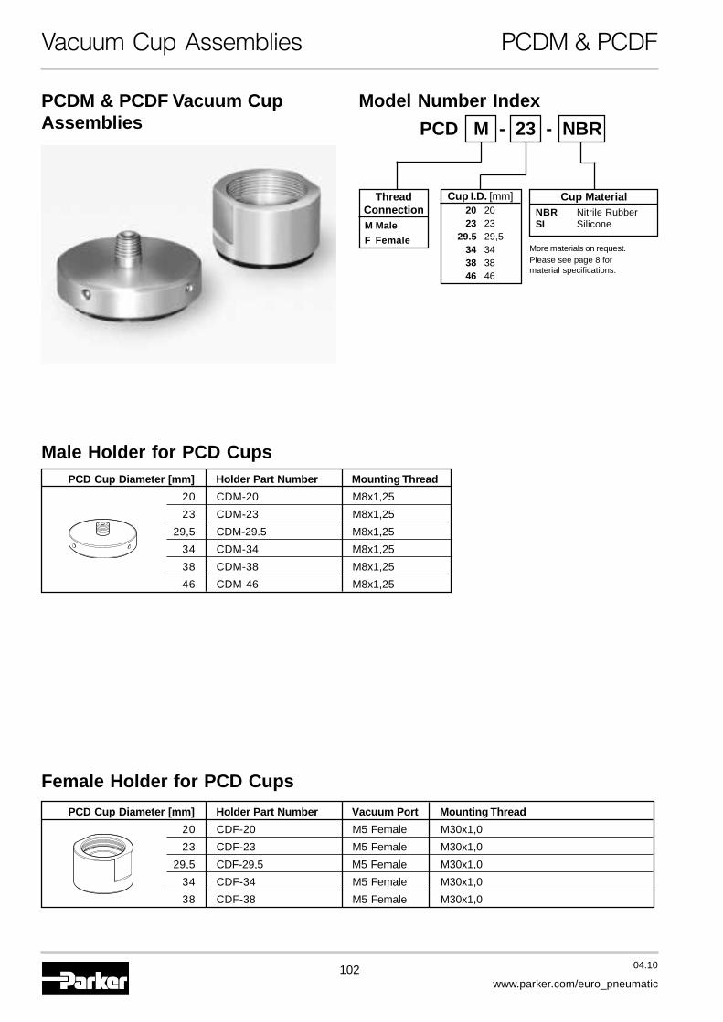
102 04.10
www.parker.com/euro_pneumatic
Vacuum Cup Assemblies PCDM & PCDF
PCDM & PCDF Vacuum CupAssemblies
Male Holder for PCD Cups
Female Holder for PCD Cups
PCD Cup Diameter [mm] Holder Part Number Mounting Thread
20 CDM-20 M8x1,25
23 CDM-23 M8x1,25
29,5 CDM-29.5 M8x1,25
34 CDM-34 M8x1,25
38 CDM-38 M8x1,25
46 CDM-46 M8x1,25
PCD Cup Diameter [mm] Holder Part Number Vacuum Port Mounting Thread
20 CDF-20 M5 Female M30x1,0
23 CDF-23 M5 Female M30x1,0
29,5 CDF-29,5 M5 Female M30x1,0
34 CDF-34 M5 Female M30x1,0
38 CDF-38 M5 Female M30x1,0
PCD M - 23 - NBR
Model Number Index
Cup I.D. [mm]20 2023 23
29.5 29,534 3438 3846 46
ThreadConnectionM Male
F Female
Cup MaterialNBR Nitrile RubberSI Silicone
More materials on request.Please see page 8 formaterial specifications.

103 04.10
www.parker.com/euro_pneumatic
A
Vacuum Cup Assemblies PCDM & PCDF
A
C
D
BF
M8
E
A
CF
D
B
JG
H
E
M30x1,0
PCDM DimensionsModel ØA B C D E F
NumberPCDM-20-* 40 22 20 26 3 10
PCDM-23-* 45 21,5 23 30 2,5 10
PCDM-29,5-* 50 21,5 29,5 36,5 2,5 10
PCDM-34-* 58 21,5 34 41 2,9 10
PCDM-38-* 60 21,5 38 45 2,5 10
PCDM-46-* 69 22 46 58 3 10
Millimeter* Cup Material
PCDF DimensionsModel ØA B C D E F G H J
NumberPCDF-20-* 40 24,5 20 26 3 16 14,5 11,5 10
PCDF-23-* 40 24 23 30 2,5 20 14,5 9 10
PCDF-29,5-* 46,5 24 29,5 36,5 2,5 6,5 14,5 9 10
PCDF-34-* 52 26 34 41 3 28,5 14,5 9 10
PCDF-38-* 56 25,4 38 45 2,5 28,5 14,5 9 10
Millimeter* Cup Material
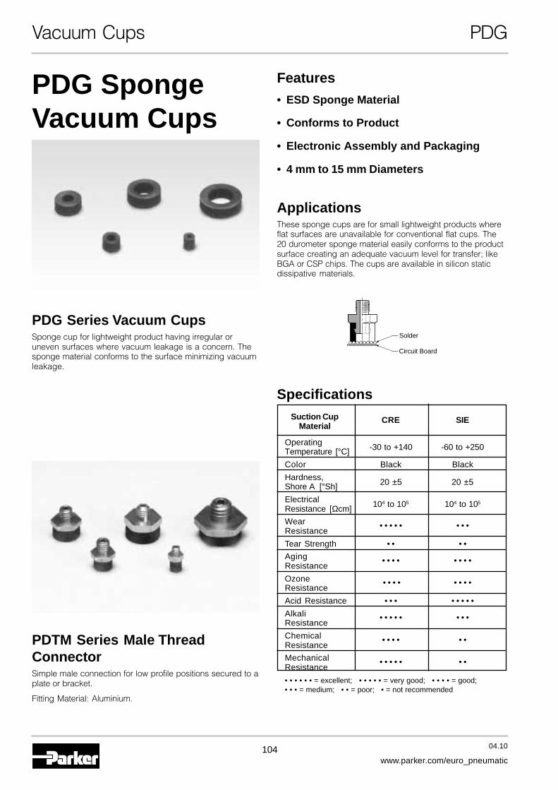
104 04.10
www.parker.com/euro_pneumatic
Vacuum Cups PDG
PDG SpongeVacuum Cups
Features
• ESD Sponge Material
• Conforms to Product
• Electronic Assembly and Packaging
• 4 mm to 15 mm Diameters
ApplicationsThese sponge cups are for small lightweight products whereflat surfaces are unavailable for conventional flat cups. The20 durometer sponge material easily conforms to the productsurface creating an adequate vacuum level for transfer; likeBGA or CSP chips. The cups are available in silicon staticdissipative materials.
PDG Series Vacuum CupsSponge cup for lightweight product having irregular oruneven surfaces where vacuum leakage is a concern. Thesponge material conforms to the surface minimizing vacuumleakage.
PDTM Series Male ThreadConnectorSimple male connection for low profile positions secured to aplate or bracket.
Fitting Material: Aluminium.
Solder
Circuit Board
SpecificationsSuction Cup CRE SIE
Material
Operating -30 to +140 -60 to +250Temperature [°C]
Color Black Black
Hardness, 20 ±5 20 ±5Shore A [°Sh]
Electrical 104 to 105 104 to 105
Resistance [Ωcm]
WearResistance
• • • • • • • •
Tear Strength • • • •
AgingResistance
• • • • • • • •
OzoneResistance
• • • • • • • •
Acid Resistance • • • • • • • •
AlkaliResistance
• • • • • • • •
ChemicalResistance
• • • • • •
MechanicalResistance
• • • • • • •
• • • • • • = excellent; • • • • • = very good; • • • • = good;• • • = medium; • • = poor; • = not recommended
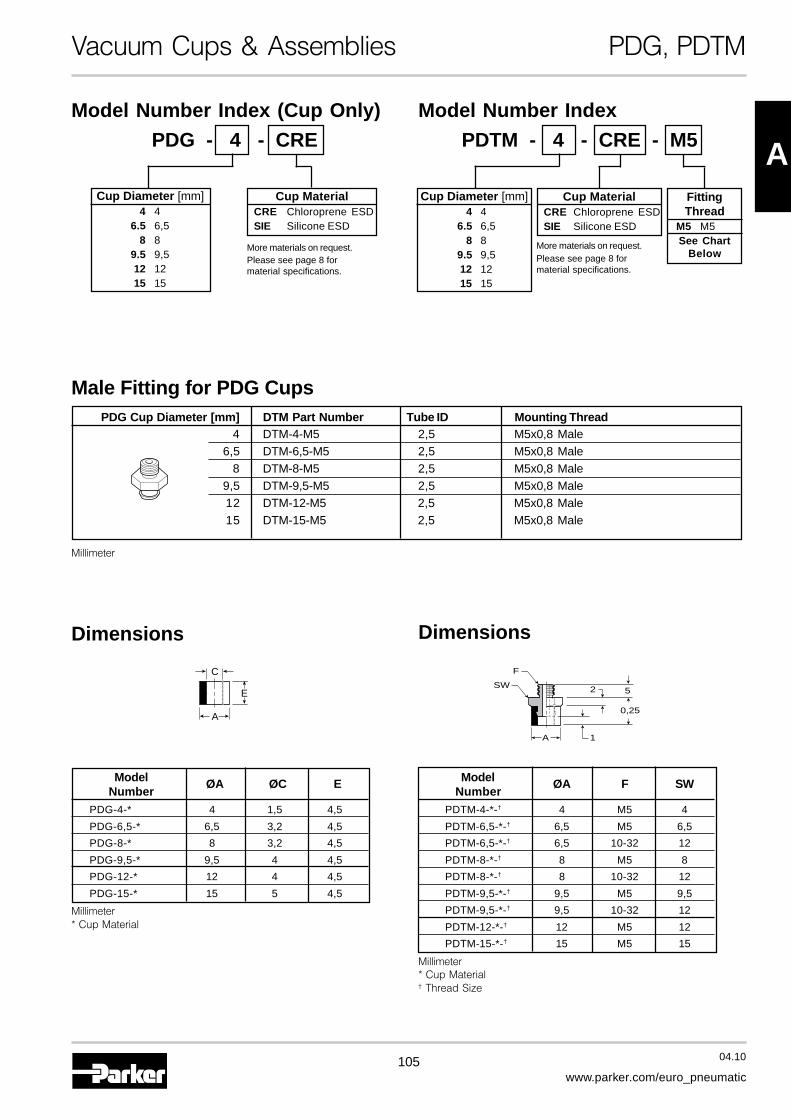
105 04.10
www.parker.com/euro_pneumatic
A
Vacuum Cups & Assemblies PDG, PDTM
PDG - 4 - CRE
Cup Diameter [mm]4 4
6.5 6,58 8
9.5 9,512 1215 15
Model Number Index (Cup Only)
PDTM - 4 - CRE - M5
Model Number Index
Cup MaterialCRE Chloroprene ESDSIE Silicone ESD
A
E
C
A 1
2
0,25
SW
F
5
Dimensions
Model ØA F SWNumber
PDTM-4-*-† 4 M5 4
PDTM-6,5-*-† 6,5 M5 6,5
PDTM-6,5-*-† 6,5 10-32 12
PDTM-8-*-† 8 M5 8
PDTM-8-*-† 8 10-32 12
PDTM-9,5-*-† 9,5 M5 9,5
PDTM-9,5-*-† 9,5 10-32 12
PDTM-12-*-† 12 M5 12
PDTM-15-*-† 15 M5 15
Millimeter* Cup Material† Thread Size
Dimensions
FittingThread
M5 M5See Chart
Below
Cup MaterialCRE Chloroprene ESDSIE Silicone ESD
Male Fitting for PDG Cups
Millimeter
Cup Diameter [mm]4 4
6.5 6,58 8
9.5 9,512 1215 15
Model ØA ØC ENumber
PDG-4-* 4 1,5 4,5
PDG-6,5-* 6,5 3,2 4,5
PDG-8-* 8 3,2 4,5
PDG-9,5-* 9,5 4 4,5
PDG-12-* 12 4 4,5
PDG-15-* 15 5 4,5
Millimeter* Cup Material
PDG Cup Diameter [mm] DTM Part Number Tube ID Mounting Thread4 DTM-4-M5 2,5 M5x0,8 Male
6,5 DTM-6,5-M5 2,5 M5x0,8 Male8 DTM-8-M5 2,5 M5x0,8 Male
9,5 DTM-9,5-M5 2,5 M5x0,8 Male12 DTM-12-M5 2,5 M5x0,8 Male15 DTM-15-M5 2,5 M5x0,8 Male
More materials on request.Please see page 8 formaterial specifications.
More materials on request.Please see page 8 formaterial specifications.
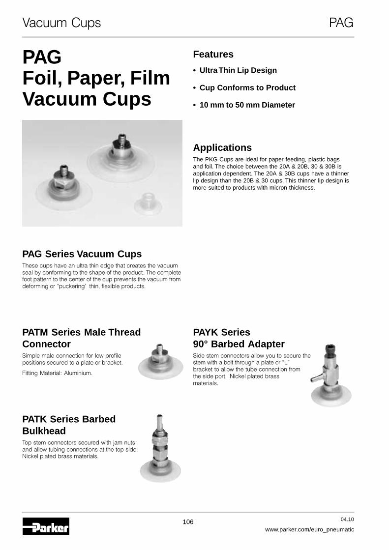
106 04.10
www.parker.com/euro_pneumatic
Vacuum Cups PAG
PAGFoil, Paper, FilmVacuum Cups
Features
• Ultra Thin Lip Design
• Cup Conforms to Product
• 10 mm to 50 mm Diameter
ApplicationsThe PKG Cups are ideal for paper feeding, plastic bagsand foil. The choice between the 20A & 20B, 30 & 30B isapplication dependent. The 20A & 30B cups have a thinnerlip design than the 20B & 30 cups. This thinner lip design ismore suited to products with micron thickness.
PAG Series Vacuum CupsThese cups have an ultra thin edge that creates the vacuumseal by conforming to the shape of the product. The completefoot pattern to the center of the cup prevents the vacuum fromdeforming or “puckering’ thin, flexible products.
PATM Series Male ThreadConnectorSimple male connection for low profilepositions secured to a plate or bracket.
Fitting Material: Aluminium.
PATK Series BarbedBulkheadTop stem connectors secured with jam nutsand allow tubing connections at the top side.Nickel plated brass materials.
PAYK Series90° Barbed AdapterSide stem connectors allow you to secure thestem with a bolt through a plate or “L”bracket to allow the tube connection fromthe side port. Nickel plated brassmaterials.
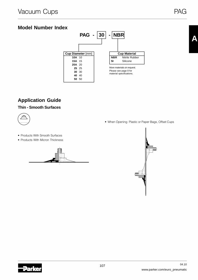
107 04.10
www.parker.com/euro_pneumatic
A
Vacuum Cups PAG
PAG - 30 - NBR
Cup Diameter [mm]10A 1015A 1520A 20
25 2530 3040 4050 50
Model Number Index
Cup MaterialNBR Nitrile RubberSI Silicone
More materials on request.Please see page 8 formaterial specifications.
Application GuideThin - Smooth Surfaces
• Products With Smooth Surfaces
• Products With Micron Thickness
• When Opening Plastic or Paper Bags, Offset Cups
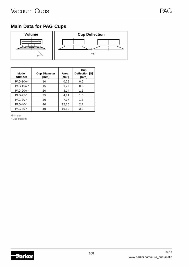
108 04.10
www.parker.com/euro_pneumatic
Vacuum Cups PAG
Main Data for PAG Cups
SV
Volume Cup Deflection
CupModel Cup Diameter Area Deflection [S]
Number [mm] [cm2] [mm]
PAG-10A-* 10 0,79 0,6
PAG-15A-* 15 1,77 0,9
PAG-20A-* 20 3,14 1,2
PAG-25-* 25 4,91 1,5
PAG-30-* 30 7,07 1,8
PAG-40-* 40 12,60 2,4
PAG-50-* 40 19,60 3,0
Millimeter* Cup Material
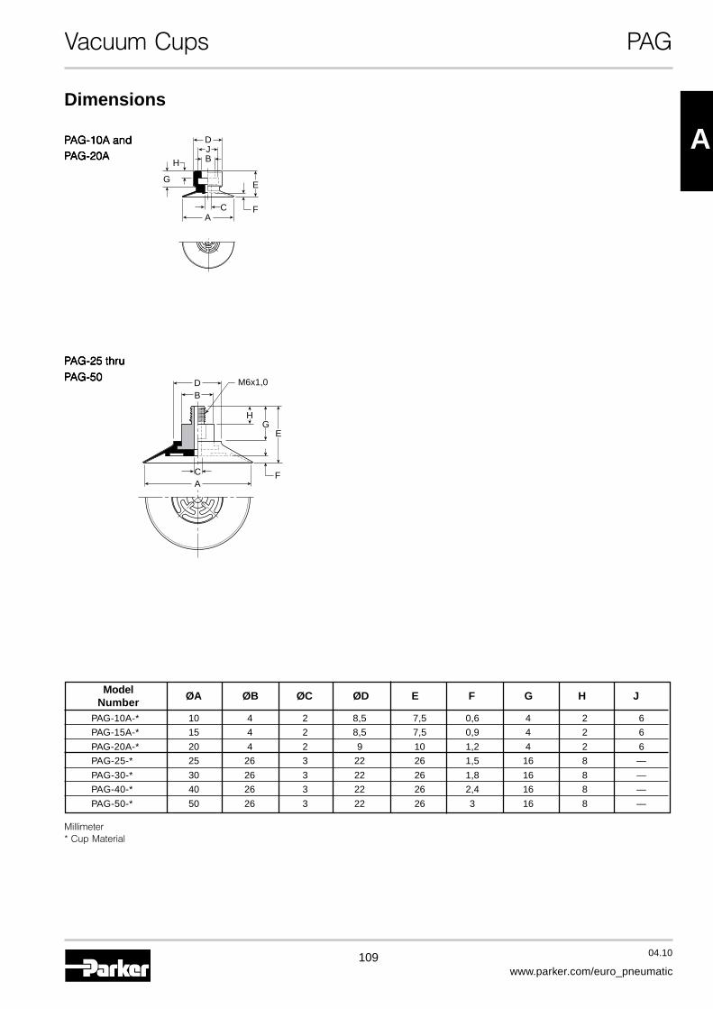
109 04.10
www.parker.com/euro_pneumatic
A
Vacuum Cups PAG
PPPPPAG-10A andAG-10A andAG-10A andAG-10A andAG-10A andPPPPPAG-20AAG-20AAG-20AAG-20AAG-20A
Dimensions
H
G
AC
B
DJ
F
E
PPPPPAG-25 thruAG-25 thruAG-25 thruAG-25 thruAG-25 thru
PPPPPAG-50AG-50AG-50AG-50AG-50
AC
BD
F
EG
H
M6x1,0
Model ØA ØB ØC ØD E F G H JNumber
PAG-10A-* 10 4 2 8,5 7,5 0,6 4 2 6
PAG-15A-* 15 4 2 8,5 7,5 0,9 4 2 6
PAG-20A-* 20 4 2 9 10 1,2 4 2 6
PAG-25-* 25 26 3 22 26 1,5 16 8 —
PAG-30-* 30 26 3 22 26 1,8 16 8 —
PAG-40-* 40 26 3 22 26 2,4 16 8 —
PAG-50-* 50 26 3 22 26 3 16 8 —
Millimeter* Cup Material
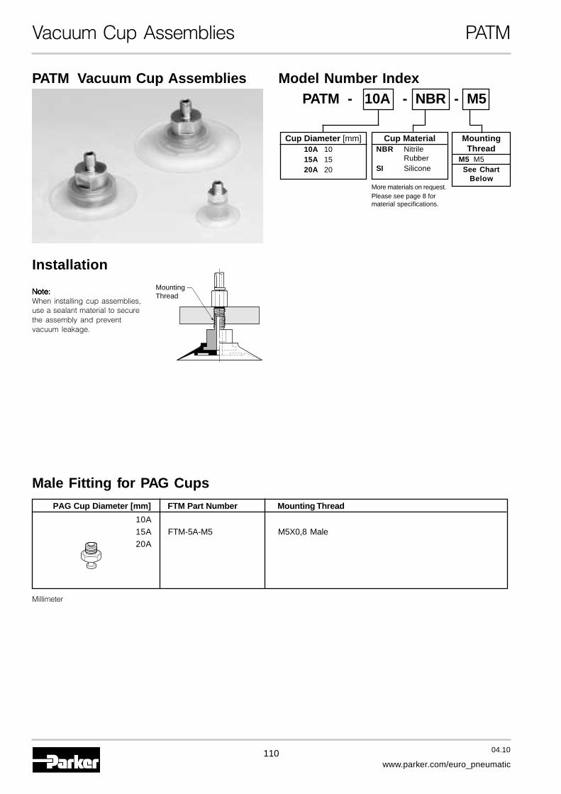
110 04.10
www.parker.com/euro_pneumatic
Vacuum Cup Assemblies PATM
PATM Vacuum Cup Assemblies
Installation
Male Fitting for PAG Cups
Model Number IndexPATM - 10A - NBR - M5
Cup MaterialNBR Nitrile
RubberSI Silicone
MountingThread
Note:Note:Note:Note:Note:When installing cup assemblies,use a sealant material to securethe assembly and preventvacuum leakage.
MountingThread
M5 M5See Chart
Below
Cup Diameter [mm]10A 1015A 1520A 20
PAG Cup Diameter [mm] FTM Part Number Mounting Thread
10A15A FTM-5A-M5 M5X0,8 Male20A
Millimeter
More materials on request.Please see page 8 formaterial specifications.

111 04.10
www.parker.com/euro_pneumatic
A
Vacuum Cup Assemblies PATM
PPPPPAAAAATM-10A thruTM-10A thruTM-10A thruTM-10A thruTM-10A thruPPPPPAAAAATM-20ATM-20ATM-20ATM-20ATM-20A
Dimensions
SW8
M5: M5x0,8
B
C
D
A E
Model ØA B C D E F G HNumber
PATM-10A-*-† 10 11 4,5 3,5 0,6 — — —
PATM-15A-*-† 15 11 4,5 3,5 0,9 — — —
PATM-20A-*-† 20 13,5 4,5 3,5 1,2 — — —
Millimeter* Cup Material† Thread Size
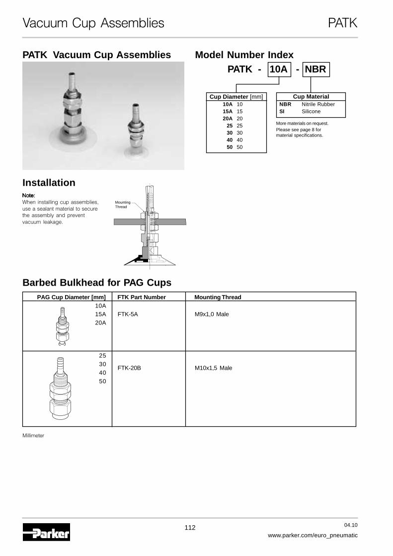
112 04.10
www.parker.com/euro_pneumatic
Vacuum Cup Assemblies PATK
PATK Vacuum Cup Assemblies
Installation
Barbed Bulkhead for PAG Cups
Model Number IndexPATK - 10A - NBR
PAG Cup Diameter [mm] FTK Part Number Mounting Thread10A15A FTK-5A M9x1,0 Male20A
2530
FTK-20B M10x1,5 Male4050
Cup MaterialNBR Nitrile RubberSI Silicone
Note:Note:Note:Note:Note:When installing cup assemblies,use a sealant material to securethe assembly and preventvacuum leakage.
Millimeter
MountingThread
Cup Diameter [mm]10A 1015A 1520A 20
25 2530 3040 4050 50
More materials on request.Please see page 8 formaterial specifications.
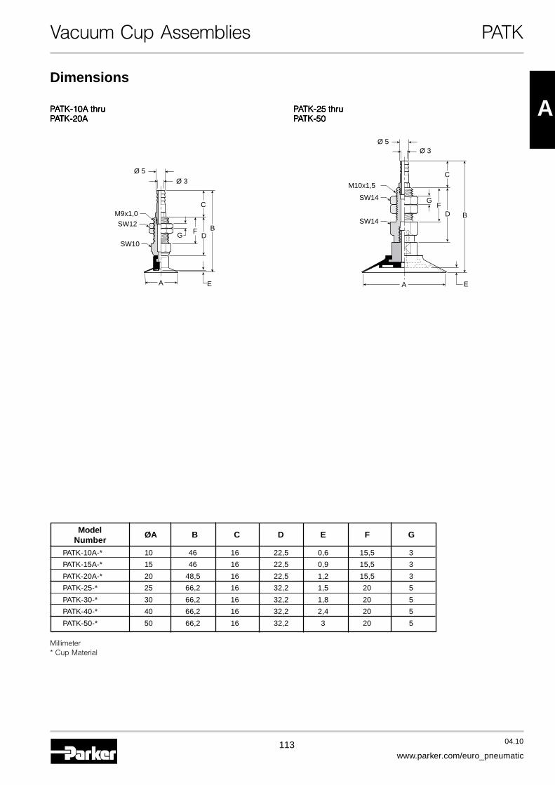
113 04.10
www.parker.com/euro_pneumatic
A
Vacuum Cup Assemblies PATK
Model ØA B C D E F GNumber
PATK-10A-* 10 46 16 22,5 0,6 15,5 3
PATK-15A-* 15 46 16 22,5 0,9 15,5 3
PATK-20A-* 20 48,5 16 22,5 1,2 15,5 3
PATK-25-* 25 66,2 16 32,2 1,5 20 5
PATK-30-* 30 66,2 16 32,2 1,8 20 5
PATK-40-* 40 66,2 16 32,2 2,4 20 5
PATK-50-* 50 66,2 16 32,2 3 20 5
Dimensions
PPPPPAAAAATK-25 thruTK-25 thruTK-25 thruTK-25 thruTK-25 thruPPPPPAAAAATK-50TK-50TK-50TK-50TK-50
EA
BFDG
M9x1,0
SW10
SW12
C
Ø 5Ø 3
BF
D
C
G
M10x1,5
SW14
SW14
Ø 5Ø 3
A E
PPPPPAAAAATK-10A thruTK-10A thruTK-10A thruTK-10A thruTK-10A thruPPPPPAAAAATK-20ATK-20ATK-20ATK-20ATK-20A
Millimeter* Cup Material
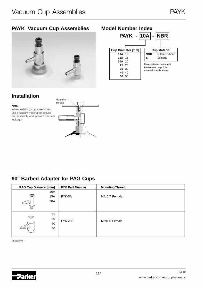
114 04.10
www.parker.com/euro_pneumatic
Vacuum Cup Assemblies PAYK
PAYK Vacuum Cup Assemblies
Installation
90° Barbed Adapter for PAG Cups
Model Number IndexPAYK - 10A - NBR
Cup MaterialNBR Nitrile RubberSI Silicone
Note:Note:Note:Note:Note:When installing cup assemblies,use a sealant material to securethe assembly and prevent vacuumleakage.
MountingThread
Cup Diameter [mm]10A 1015A 1520A 20
25 2530 3040 4050 50
PAG Cup Diameter [mm] FYK Part Number Mounting Thread10A
15A FYK-5A M4x0,7 Female
20A
25
30FYK-20B M6x1,0 Female
40
50
Millimeter
More materials on request.Please see page 8 formaterial specifications.
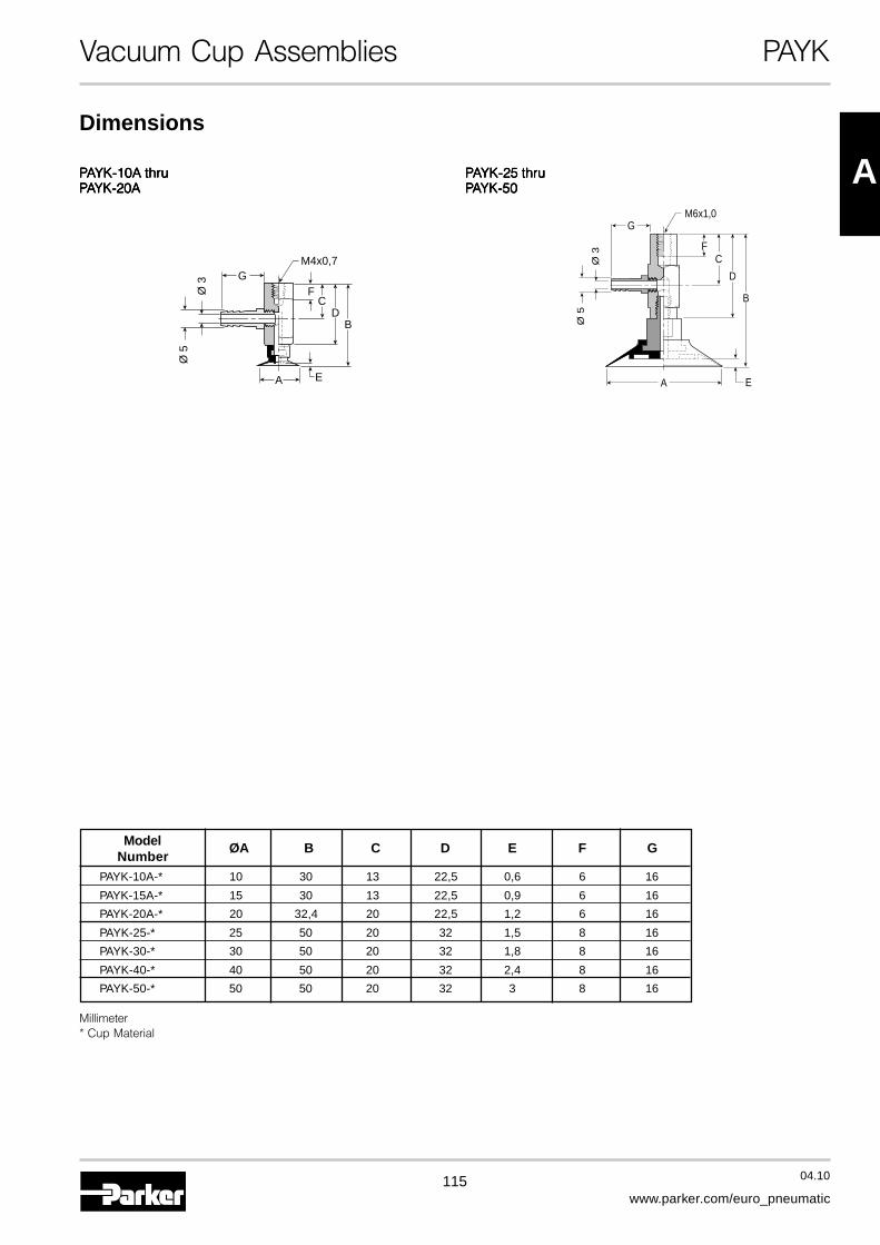
115 04.10
www.parker.com/euro_pneumatic
A
Vacuum Cup Assemblies PAYK
Dimensions
PPPPPAAAAAYK-25 thruYK-25 thruYK-25 thruYK-25 thruYK-25 thruPPPPPAAAAAYK-50YK-50YK-50YK-50YK-50
PPPPPAAAAAYK-10A thruYK-10A thruYK-10A thruYK-10A thruYK-10A thruPPPPPAAAAAYK-20AYK-20AYK-20AYK-20AYK-20A
FC
DB
E
Ø 5
Ø 3
M4x0,7G
A
B
F
GM6x1,0
C
D
Ø 5
Ø 3
A E
Model ØA B C D E F GNumber
PAYK-10A-* 10 30 13 22,5 0,6 6 16
PAYK-15A-* 15 30 13 22,5 0,9 6 16
PAYK-20A-* 20 32,4 20 22,5 1,2 6 16
PAYK-25-* 25 50 20 32 1,5 8 16
PAYK-30-* 30 50 20 32 1,8 8 16
PAYK-40-* 40 50 20 32 2,4 8 16
PAYK-50-* 50 50 20 32 3 8 16
Millimeter* Cup Material