Embed Size (px)
Citation preview
Sample Dynamic Analysis Design Report 3400m uground cv.doc Page 1 of 28
CONVEYOR DESIGN REVIEW
Prepared for
HELIX SAMPLE REPORT A Company Name
Address 1, CITY NSW 2005
Prepared by Helix Technologies Pty Ltd
PO Box 610 Morley WA 6943
Perth Australia
Tel +61 8 9275 0635 Email: [email protected]
22/09/2005
CONVEYOR NUMBER BT411/2 COMBINED
ABC Consulting
Sample Dynamic Analysis Design Report 3400m uground cv.doc Page 2 of 28
Table of Contents
1 INTRODUCTION ........................................................................................................................................ 4 2 OBJECTIVE................................................................................................................................................ 4 3 BASIC DESCRIPTION OF CONVEYOR.................................................................................................... 4
3.1 Basic Dimensions and Capacity.......................................................................................................... 4 3.2 Drives................................................................................................................................................... 4 3.3 Takeup................................................................................................................................................. 4 3.4 Conveyor Belt ...................................................................................................................................... 4 3.5 Idlers .................................................................................................................................................... 4 3.6 Schematic of Conveyor ....................................................................................................................... 5 3.7 Conveyor Plan and Longsection ......................................................................................................... 5
4 GENERAL DESIGN OBSERVATIONS - STATIC ANALYSIS ................................................................... 6 4.1 Belt Rating and Belt Tensions ............................................................................................................. 6 4.2 Belt Speed and Capacity ..................................................................................................................... 7 4.3 Conveyor Friction Factor ..................................................................................................................... 7 4.4 Demand and Installed Power .............................................................................................................. 7 4.5 Takeup and Drive Traction .................................................................................................................. 7 4.6 Carry and Return Idlers ....................................................................................................................... 7 4.7 Speed Reducer.................................................................................................................................... 8 4.8 Fluid Couplings and Conveyor Starting............................................................................................... 8 4.9 Conveyor Stopping .............................................................................................................................. 8 4.10 Vertical Curve Radii ......................................................................................................................... 8 4.11 Conveyor Pulleys and Shafts........................................................................................................... 8
5 DYNAMIC ANALSYIS - HIGH FRICTION CASE (F = 0.025)..................................................................... 9 5.1 Starting Torque Curve for Voith TVVS 562 Coupling.......................................................................... 9 5.2 Starting Fully Loaded........................................................................................................................... 9 5.3 Starting Empty - 2 Drives................................................................................................................... 12 5.4 Starting Empty - 1 Drive .................................................................................................................... 13 5.5 Stopping Fully Loaded - locked takeup ............................................................................................. 14 5.6 Stopping Empty - 13800kg takeup .................................................................................................... 16
6 DYNAMIC ANALYSIS - LOW FRICTION CASE ...................................................................................... 18 6.1 Starting Fully Loaded......................................................................................................................... 18 6.2 Starting Empty - 2 Drives................................................................................................................... 20 6.3 Starting Empty - 1 Drive .................................................................................................................... 22 6.4 Stopping Fully Loaded - locked takeup ............................................................................................. 23 6.5 Stopping Empty - 12400kg takeup .................................................................................................... 25
7 SUMMARY AND CONCLUSIONS ........................................................................................................... 27 8 APPENDICES........................................................................................................................................... 28
8.1 Bt411-2 Static Design Reports high friction.pdf................................................................................. 28 8.2 Bt411-2 Static Design Reports low friction.pdf .................................................................................. 28 8.3 Bt411-2 Dynamics Starting Full High Friction.pdf.............................................................................. 28 8.4 Bt411-2 Dynamics Starting Full Low Friction.pdf .............................................................................. 28
Conveyor BT411/2
Sample Dynamic Analysis Design Report 3400m uground cv.doc / September 05
Page 3 of 28
8.5 Bt411-2 Dynamics Starting Empty High Friction 2 drives.pdf ........................................................... 28 8.6 Bt411-2 Dynamics Starting Empty High Friction 1 drive.pdf ............................................................. 28 8.7 Bt411-2 Dynamics Starting Empty Low Friction 2 drives.pdf ............................................................ 28 8.8 Bt411-2 Dynamics Starting Empty Low Friction 1 drives.pdf ............................................................ 28 8.9 Bt411-2 Dynamics Stopping Full High Friction takeup locked.pdf .................................................... 28 8.10 Bt411-2 Dynamics Stopping Full Low Friction takeup locked.pdf.................................................. 28 8.11 Bt411-2 Dynamics Stopping Empty High Friction takeup locked.pdf ............................................ 28 8.12 Bt411-2 Dynamics Stopping Empty Low Friction takeup locked.pdf ............................................. 28
Conveyor BT411/2
Sample Dynamic Analysis Design Report 3400m uground cv.doc / September 05
Page 4 of 28
1 INTRODUCTION A design review of a combined Conveyor number BT411/2 has been undertaken by Helix Technologies Pty Ltd for ABC Consulting. A model of the conveyor was built by ABC Consulting in the Helix delta-T software program and transmitted to Helix Technologies. Minor adjustments to the input data have been made by Helix Technologies in order to refine the design of the conveyor, and then a series of Dynamic Analysis calculations have been performed. Detailed design reports obtained from the Helix delta-T software have been attached in the appendices. This report summarises the detailed reports and highlights certain observations made during the review process.
2 OBJECTIVE
The objective of this report is to review the design of the conveyor and confirm the suitability of the equipment selected for the conveyor. In addition, the Dynamic analysis results have been reviewed and recommendations made on the operation of the conveyor.
3 BASIC DESCRIPTION OF CONVEYOR
3.1 Basic Dimensions and Capacity
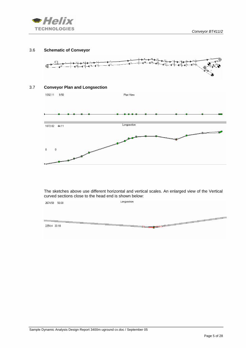
The conveyor is 3400m long and has a lift of 54m. Design capacity is 550 tph of coal. There are concave and convex vertical curves near the head as well as near the tail of the conveyor. The design capacity has been determined as the maximum which can be achieved with this belt rating.
3.2 Drives
The conveyor is fitted with two Drive pulleys, each with a 250kW drive.
3.3 Takeup
A Looped belt storage device and winch takeup are fitted after the head drive on the return belt run. Takeup tension is maintained at 44.2kN. This takeup is clamped on stopping the conveyor.
3.4 Conveyor Belt
Belt width is 1200mm. Conveyor Belt is FENAPLAST FR 6500 EHD. Belt speed is 4m/s.
3.5 Idlers
Carry idlers are 3 roll, 35 degree trough, 152mm roll diameter spaced at 1.5m. Return idlers are 2 roll 10 degree trough, 152 mm roll diameter idlers spaced at 3.0 m.
Conveyor BT411/2
Sample Dynamic Analysis Design Report 3400m uground cv.doc / September 05
Page 5 of 28
3.6 Schematic of Conveyor
3.7 Conveyor Plan and Longsection
The sketches above use different horizontal and vertical scales. An enlarged view of the Vertical curved sections close to the head end is shown below:
Conveyor BT411/2
Sample Dynamic Analysis Design Report 3400m uground cv.doc / September 05
Page 6 of 28
4 GENERAL DESIGN OBSERVATIONS - STATIC ANALYSIS
4.1 Belt Rating and Belt Tensions
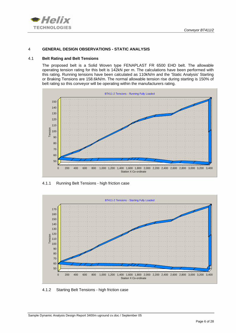
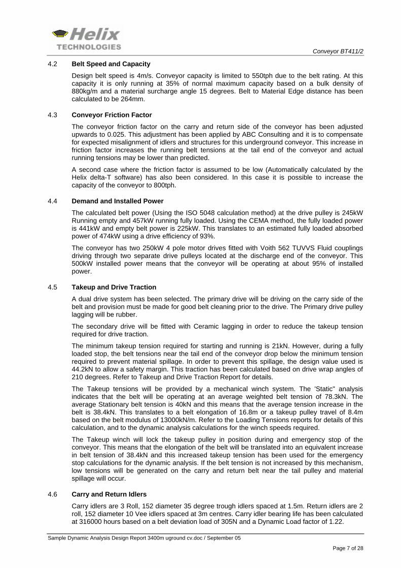
The proposed belt is a Solid Woven type FENAPLAST FR 6500 EHD belt. The allowable operating tension rating for this belt is 142kN per m. The calculations have been performed with this rating. Running tensions have been calculated as 110kN/m and the 'Static Analysis' Starting or Braking Tensions are 158.6kN/m. The normal allowable tension rise during starting is 150% of belt rating so this conveyor will be operating within the manufacturers rating.
BT411-2 Tensions - Running Fully Loaded
Station X Co-ordinate3,4003,2003,0002,8002,6002,4002,2002,0001,8001,6001,4001,2001,0008006004002000
Tens
ion
150
140
130
120
110
100
90
80
70
60
50
4.1.1 Running Belt Tensions - high friction case
BT411-2 Tensions - Starting Fully Loaded
Station X Co-ordinate3,4003,2003,0002,8002,6002,4002,2002,0001,8001,6001,4001,2001,0008006004002000
Tens
ion
170
160
150
140
130
120
110
100
90
80
70
60
50
4.1.2 Starting Belt Tensions - high friction case
Conveyor BT411/2
Sample Dynamic Analysis Design Report 3400m uground cv.doc / September 05
Page 7 of 28
4.2 Belt Speed and Capacity
Design belt speed is 4m/s. Conveyor capacity is limited to 550tph due to the belt rating. At this capacity it is only running at 35% of normal maximum capacity based on a bulk density of 880kg/m and a material surcharge angle 15 degrees. Belt to Material Edge distance has been calculated to be 264mm.
4.3 Conveyor Friction Factor
The conveyor friction factor on the carry and return side of the conveyor has been adjusted upwards to 0.025. This adjustment has been applied by ABC Consulting and it is to compensate for expected misalignment of idlers and structures for this underground conveyor. This increase in friction factor increases the running belt tensions at the tail end of the conveyor and actual running tensions may be lower than predicted.
A second case where the friction factor is assumed to be low (Automatically calculated by the Helix delta-T software) has also been considered. In this case it is possible to increase the capacity of the conveyor to 800tph.
4.4 Demand and Installed Power
The calculated belt power (Using the ISO 5048 calculation method) at the drive pulley is 245kW Running empty and 457kW running fully loaded. Using the CEMA method, the fully loaded power is 441kW and empty belt power is 225kW. This translates to an estimated fully loaded absorbed power of 474kW using a drive efficiency of 93%.
The conveyor has two 250kW 4 pole motor drives fitted with Voith 562 TUVVS Fluid couplings driving through two separate drive pulleys located at the discharge end of the conveyor. This 500kW installed power means that the conveyor will be operating at about 95% of installed power.
4.5 Takeup and Drive Traction
A dual drive system has been selected. The primary drive will be driving on the carry side of the belt and provision must be made for good belt cleaning prior to the drive. The Primary drive pulley lagging will be rubber.
The secondary drive will be fitted with Ceramic lagging in order to reduce the takeup tension required for drive traction.
The minimum takeup tension required for starting and running is 21kN. However, during a fully loaded stop, the belt tensions near the tail end of the conveyor drop below the minimum tension required to prevent material spillage. In order to prevent this spillage, the design value used is 44.2kN to allow a safety margin. This traction has been calculated based on drive wrap angles of 210 degrees. Refer to Takeup and Drive Traction Report for details.
The Takeup tensions will be provided by a mechanical winch system. The 'Static" analysis indicates that the belt will be operating at an average weighted belt tension of 78.3kN. The average Stationary belt tension is 40kN and this means that the average tension increase in the belt is 38.4kN. This translates to a belt elongation of 16.8m or a takeup pulley travel of 8.4m based on the belt modulus of 13000kN/m. Refer to the Loading Tensions reports for details of this calculation, and to the dynamic analysis calculations for the winch speeds required.
The Takeup winch will lock the takeup pulley in position during and emergency stop of the conveyor. This means that the elongation of the belt will be translated into an equivalent increase in belt tension of 38.4kN and this increased takeup tension has been used for the emergency stop calculations for the dynamic analysis. If the belt tension is not increased by this mechanism, low tensions will be generated on the carry and return belt near the tail pulley and material spillage will occur.
4.6 Carry and Return Idlers
Carry idlers are 3 Roll, 152 diameter 35 degree trough idlers spaced at 1.5m. Return idlers are 2 roll, 152 diameter 10 Vee idlers spaced at 3m centres. Carry idler bearing life has been calculated at 316000 hours based on a belt deviation load of 305N and a Dynamic Load factor of 1.22.
Conveyor BT411/2
Sample Dynamic Analysis Design Report 3400m uground cv.doc / September 05
Page 8 of 28
Return Idlers also have adequate bearing life and shaft deflections for both carry and return are within limits. Refer to Idler Report for more details.
4.7 Speed Reducer
A speed reducer with a ratio of 19.84:1 is required in order to match the belt speed to the design speed. Actual ratio selected will depend on manufacturer. An allowable Fluid Coupling Slip of 3% has been factored into the required ratio.
4.8 Fluid Couplings and Conveyor Starting
Each drive will have a Voith size 562 TUVVS Fluid Coupling installed between the electric motor and the input shaft of the speed reducer. These couplings have a delay fill oil chamber which enables them to deliver a soft start to the conveyor drive pulley. The peak torque used for the starting calculations has been set to 110% of motor full load torque for the Starting Fully Loaded case. The 110% value was obtained from performance curves provided by the manufacturer. This starting torque yields a calculated starting time of 63 seconds for the fully loaded conveyor. The calculated 'Static' or 'Rigid Body' belt tensions during this starting are predicted to be 147kN/m - see the Starting and Stopping Report.
For starting empty, the predicted starting time is calculated as 14.3 seconds if the same torque is developed as for the fully loaded start and both drives are started.
It is recommended that for empty belt starting only the secondary drive should be used to start the conveyor. Once the belt is up to full speed, the primary drive can be activated and then material can be fed to the conveyor.
4.9 Conveyor Stopping
Due to the significant lift in the conveyor, the material mass tends to stop the conveyor quickly when power is cut to the drives. The locking of the takeup pulley increases the average belt tensions and will assist in preventing the low tension waves generated by removal of the driving force from causing material spillage. The calculated stopping time for the loaded conveyor is 14.5 seconds and for the empty conveyor it is 19.3 seconds. Belt drift and material discharge masses and volumes can be seen on the Starting & Stopping Report. No brakes have been fitted for retardation purposes.
4.10 Vertical Curve Radii
The conveyor has convex and concave vertical curves near the tail and near the discharge end of the conveyor. A review of the Vertical Curve report shows that the convex curves near the tail require a radius of 62m and the convex curves near the head end require 57m. Due to the short length of curve, a radius of 400m may be used if practically possible.
For the concave curves, a radius of 705m is required near the tail and 1005m near the head end, so it is recommended that 800m and 1200m be used if geometry allows this. A shorter radius can be accommodated if required as these figures include a safety factor of 1.2 and are for a worn conveyor belt.
4.11 Conveyor Pulleys and Shafts
Conveyor Drive pulley diameters have been selected as 1000mm over steel. The high tension head pulley is 900 diameter and the other pulleys in the conveyor 500mm. The belt manufacturer recommends minimum pulley diameters of 630mm down to 400mm so these sizes will be adequate. Pulley shaft sizes have been estimated in the design reports, however, detailed design checks with actual overhung loads are recommended.
Conveyor BT411/2
Sample Dynamic Analysis Design Report 3400m uground cv.doc / September 05
Page 9 of 28
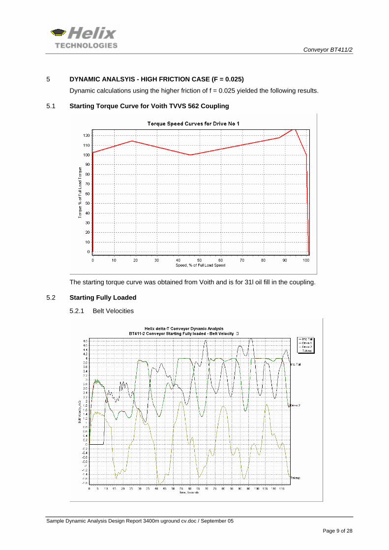
5 DYNAMIC ANALSYIS - HIGH FRICTION CASE (F = 0.025)
Dynamic calculations using the higher friction of f = 0.025 yielded the following results.
5.1 Starting Torque Curve for Voith TVVS 562 Coupling
The starting torque curve was obtained from Voith and is for 31l oil fill in the coupling.
5.2 Starting Fully Loaded
5.2.1 Belt Velocities
Conveyor BT411/2
Sample Dynamic Analysis Design Report 3400m uground cv.doc / September 05
Page 10 of 28
The fully loaded start results in the Drive pulleys reaching full speed after about 30 seconds. The tail pulley starts to move after 8 seconds and accelerates rapidly. The tail pulley speed actually goes well over the design speed and peaks at 4.85m/s. The tail pulley speed will oscillate for a period of time before settling at the design speed.
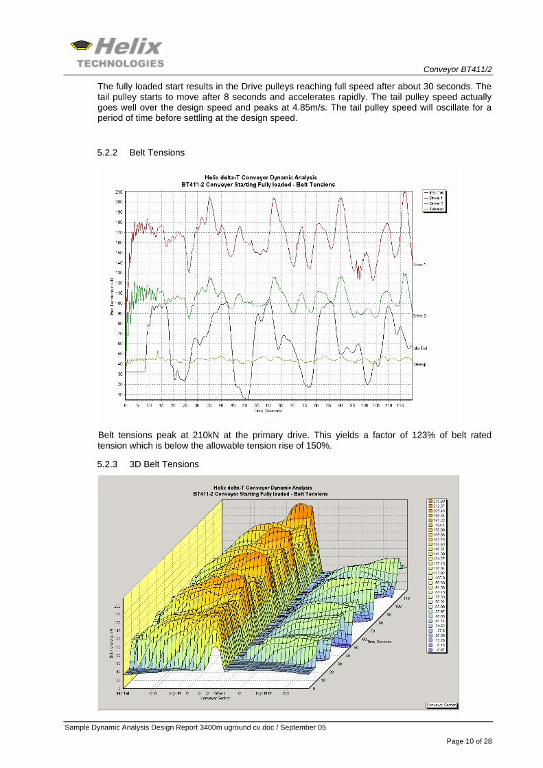
5.2.2 Belt Tensions
Belt tensions peak at 210kN at the primary drive. This yields a factor of 123% of belt rated tension which is below the allowable tension rise of 150%.
5.2.3 3D Belt Tensions
Conveyor BT411/2
Sample Dynamic Analysis Design Report 3400m uground cv.doc / September 05
Page 11 of 28
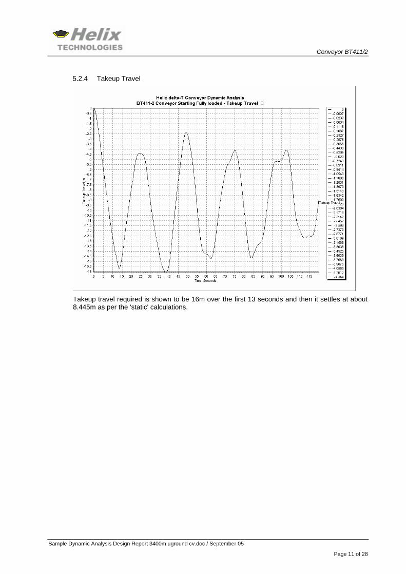
5.2.4 Takeup Travel
Takeup travel required is shown to be 16m over the first 13 seconds and then it settles at about 8.445m as per the 'static' calculations.
Conveyor BT411/2
Sample Dynamic Analysis Design Report 3400m uground cv.doc / September 05
Page 12 of 28
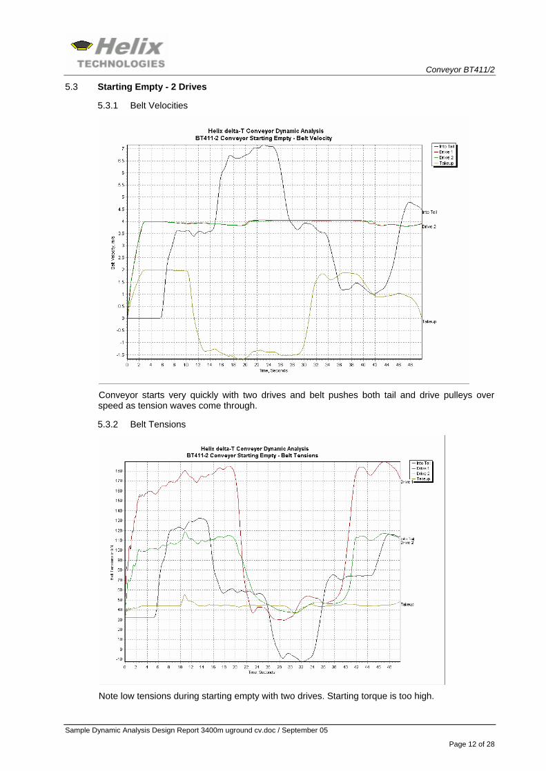
5.3 Starting Empty - 2 Drives
5.3.1 Belt Velocities
Conveyor starts very quickly with two drives and belt pushes both tail and drive pulleys over speed as tension waves come through.
5.3.2 Belt Tensions
Note low tensions during starting empty with two drives. Starting torque is too high.
Conveyor BT411/2
Sample Dynamic Analysis Design Report 3400m uground cv.doc / September 05
Page 13 of 28
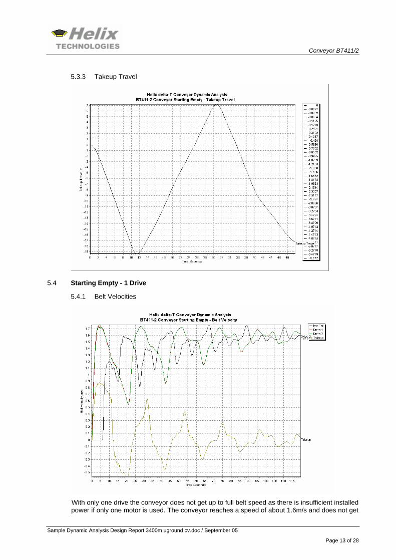
5.3.3 Takeup Travel
5.4 Starting Empty - 1 Drive
5.4.1 Belt Velocities
With only one drive the conveyor does not get up to full belt speed as there is insufficient installed power if only one motor is used. The conveyor reaches a speed of about 1.6m/s and does not get
Conveyor BT411/2
Sample Dynamic Analysis Design Report 3400m uground cv.doc / September 05
Page 14 of 28
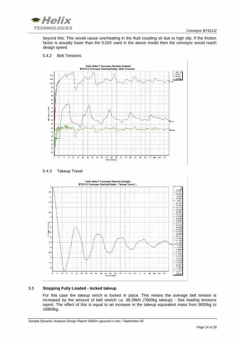
beyond this. This would cause overheating in the fluid coupling oil due to high slip. If the friction factor is actually lower than the 0.025 used in the above model then the conveyor would reach design speed.
5.4.2 Belt Tensions
5.4.3 Takeup Travel
5.5 Stopping Fully Loaded - locked takeup
For this case the takeup winch is locked in place. This means the average belt tension is increased by the amount of belt stretch i.e. 38.39kN (7800kg takeup) - See loading tensions report. The effect of this is equal to an increase in the takeup equivalent mass from 9000kg to 16800kg.
Conveyor BT411/2
Sample Dynamic Analysis Design Report 3400m uground cv.doc / September 05
Page 15 of 28
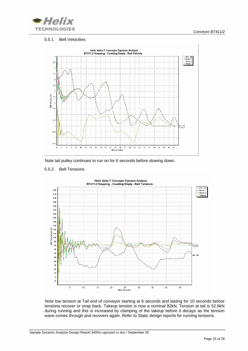
5.5.1 Belt Velocities
Note tail pulley continues to run on for 6 seconds before slowing down.
5.5.2 Belt Tensions
Note low tension at Tail end of conveyor starting at 6 seconds and lasting for 10 seconds before tensions recover or snap back. Takeup tension is now a nominal 82kN. Tension at tail is 52.6kN during running and this is increased by clamping of the takeup before it decays as the tension wave comes through and recovers again. Refer to Static design reports for running tensions.
Conveyor BT411/2
Sample Dynamic Analysis Design Report 3400m uground cv.doc / September 05
Page 16 of 28
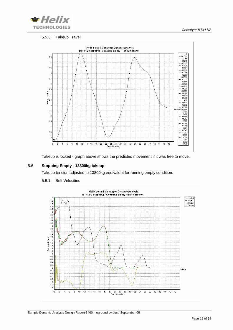
5.5.3 Takeup Travel
Takeup is locked - graph above shows the predicted movement if it was free to move.
5.6 Stopping Empty - 13800kg takeup
Takeup tension adjusted to 13800kg equivalent for running empty condition.
5.6.1 Belt Velocities
Conveyor BT411/2
Sample Dynamic Analysis Design Report 3400m uground cv.doc / September 05
Page 17 of 28
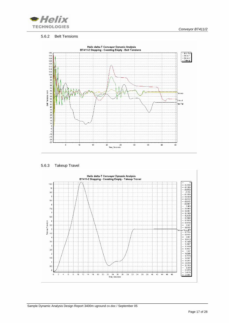
5.6.2 Belt Tensions
5.6.3 Takeup Travel
Conveyor BT411/2
Sample Dynamic Analysis Design Report 3400m uground cv.doc / September 05
Page 18 of 28
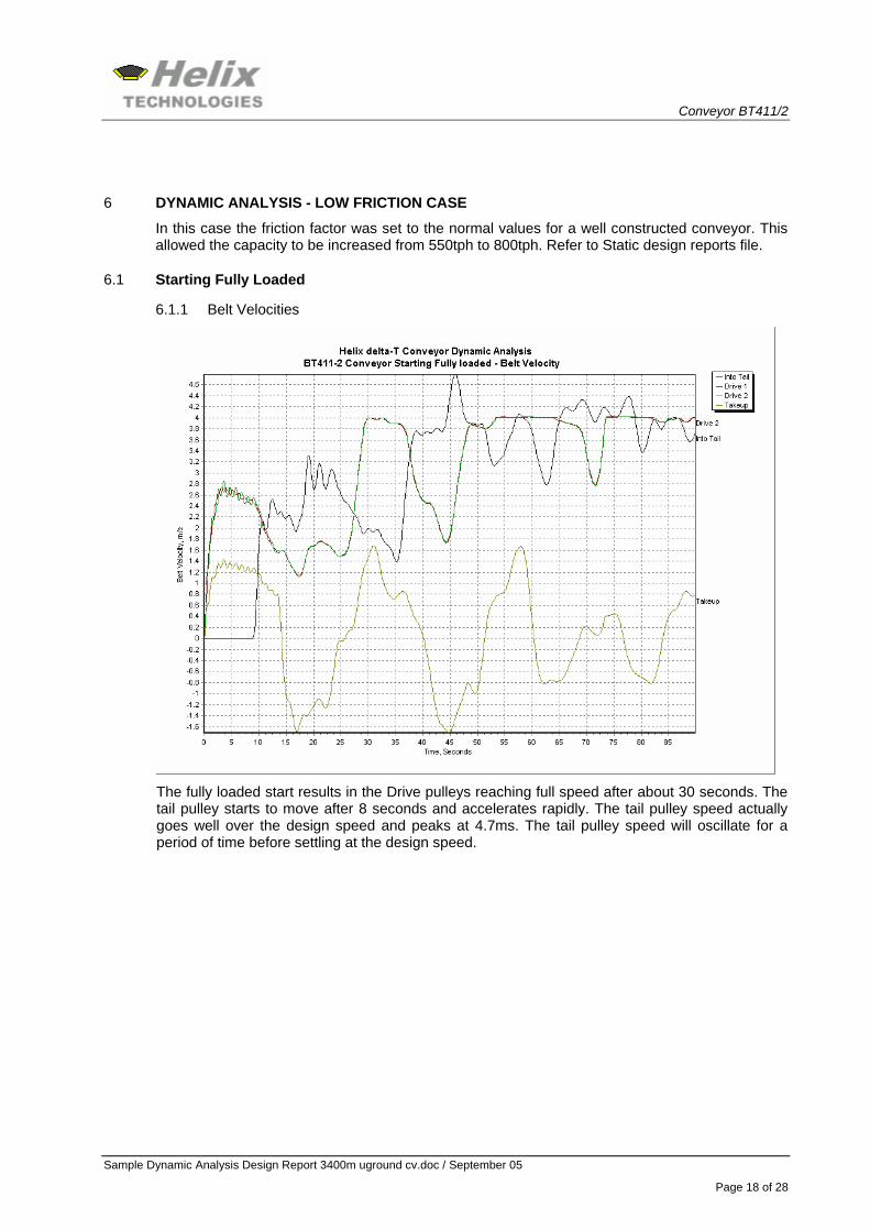
6 DYNAMIC ANALYSIS - LOW FRICTION CASE
In this case the friction factor was set to the normal values for a well constructed conveyor. This allowed the capacity to be increased from 550tph to 800tph. Refer to Static design reports file.
6.1 Starting Fully Loaded
6.1.1 Belt Velocities
The fully loaded start results in the Drive pulleys reaching full speed after about 30 seconds. The tail pulley starts to move after 8 seconds and accelerates rapidly. The tail pulley speed actually goes well over the design speed and peaks at 4.7ms. The tail pulley speed will oscillate for a period of time before settling at the design speed.
Conveyor BT411/2
Sample Dynamic Analysis Design Report 3400m uground cv.doc / September 05
Page 19 of 28
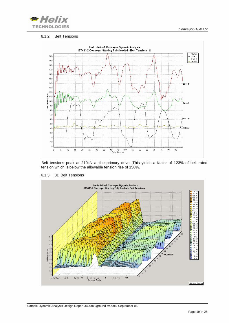
6.1.2 Belt Tensions
Belt tensions peak at 210kN at the primary drive. This yields a factor of 123% of belt rated tension which is below the allowable tension rise of 150%.
6.1.3 3D Belt Tensions
Conveyor BT411/2
Sample Dynamic Analysis Design Report 3400m uground cv.doc / September 05
Page 20 of 28
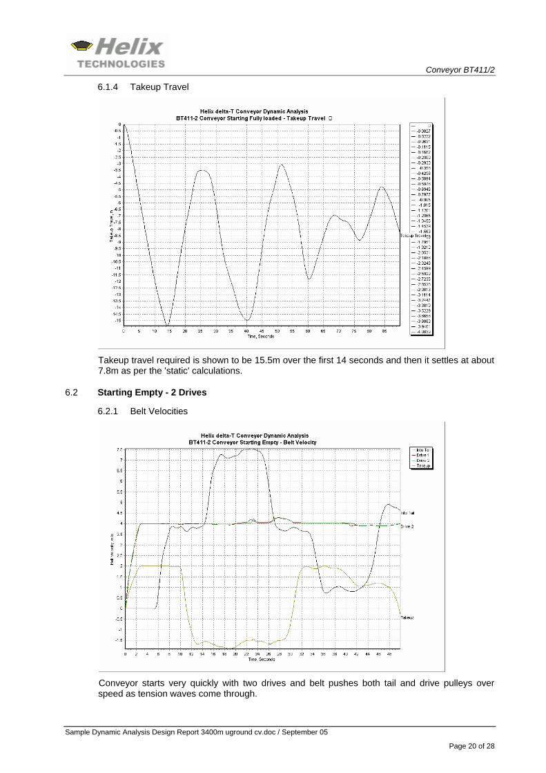
6.1.4 Takeup Travel
Takeup travel required is shown to be 15.5m over the first 14 seconds and then it settles at about 7.8m as per the 'static' calculations.
6.2 Starting Empty - 2 Drives
6.2.1 Belt Velocities
Conveyor starts very quickly with two drives and belt pushes both tail and drive pulleys over speed as tension waves come through.
Conveyor BT411/2
Sample Dynamic Analysis Design Report 3400m uground cv.doc / September 05
Page 21 of 28
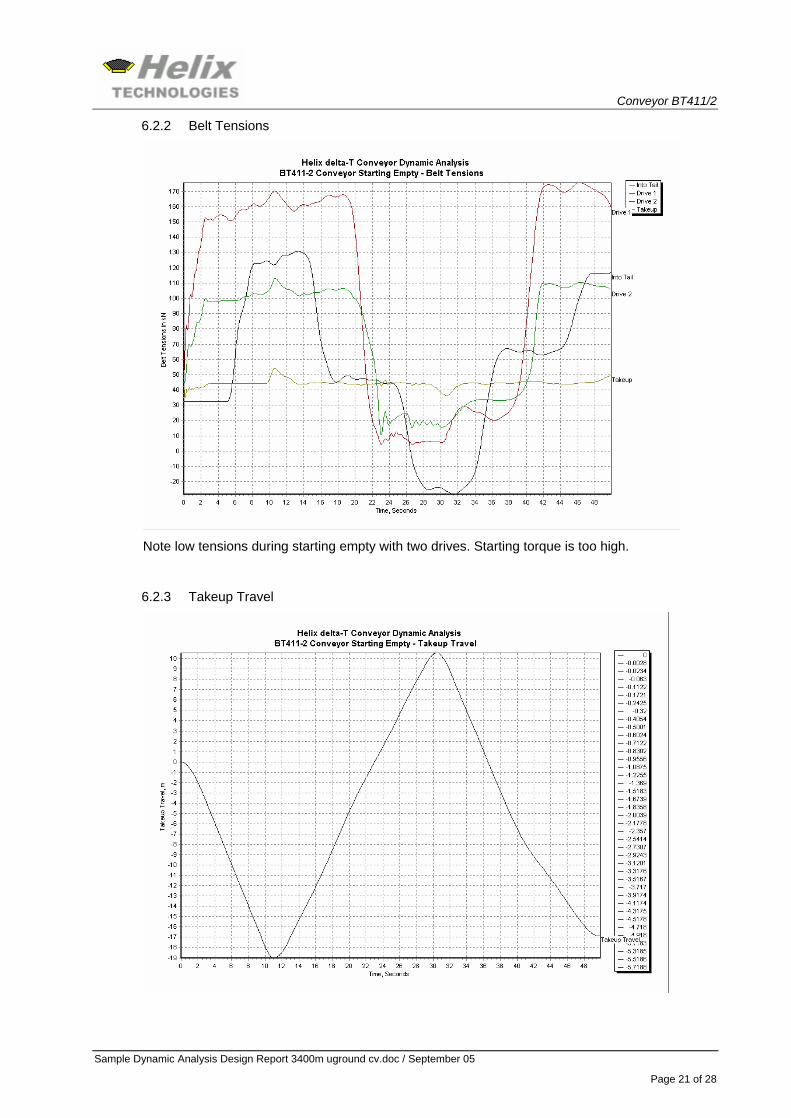
6.2.2 Belt Tensions
Note low tensions during starting empty with two drives. Starting torque is too high.
6.2.3 Takeup Travel
Conveyor BT411/2
Sample Dynamic Analysis Design Report 3400m uground cv.doc / September 05
Page 22 of 28
6.3 Starting Empty - 1 Drive
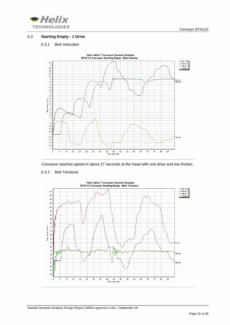
6.3.1 Belt Velocities
Conveyor reaches speed in about 27 seconds at the head with one drive and low friction.
6.3.2 Belt Tensions
Conveyor BT411/2
Sample Dynamic Analysis Design Report 3400m uground cv.doc / September 05
Page 23 of 28
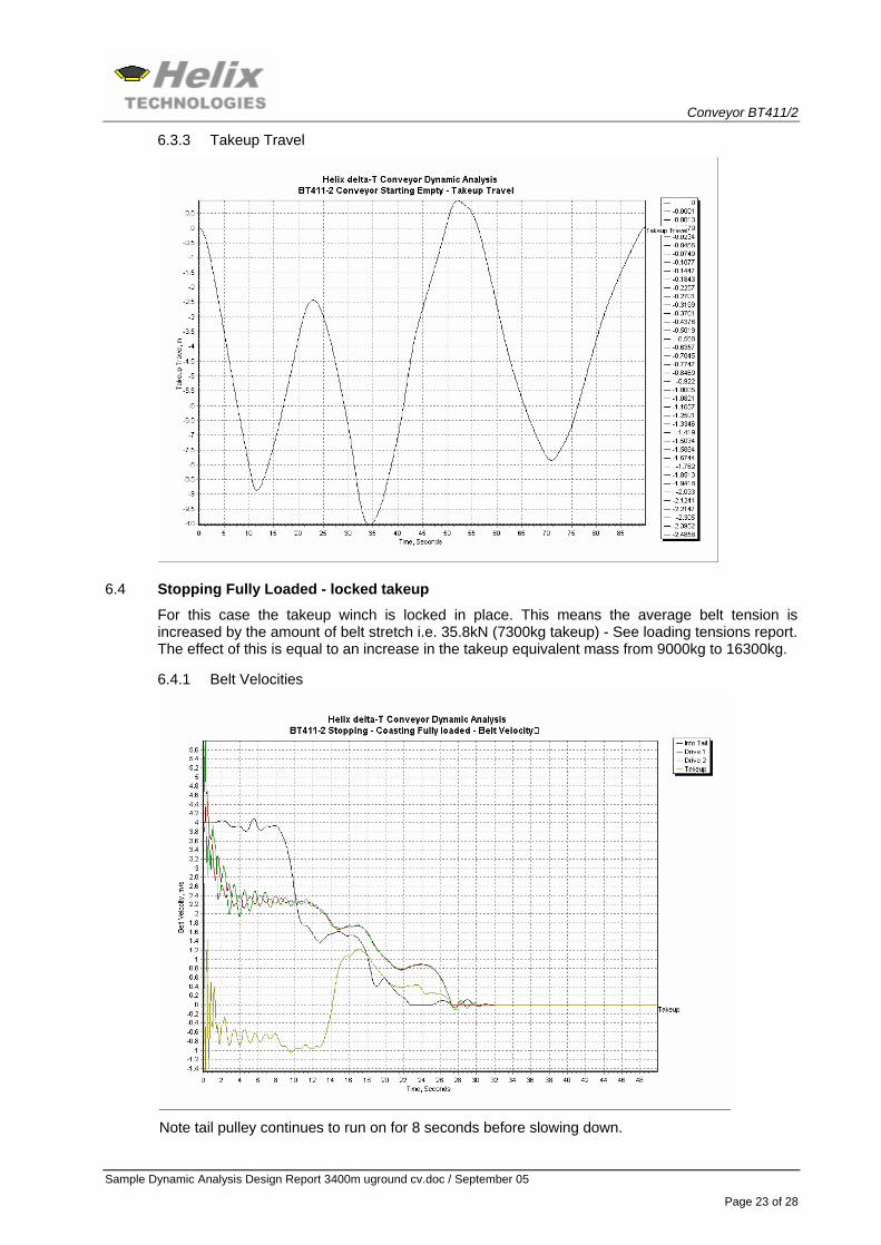
6.3.3 Takeup Travel
6.4 Stopping Fully Loaded - locked takeup
For this case the takeup winch is locked in place. This means the average belt tension is increased by the amount of belt stretch i.e. 35.8kN (7300kg takeup) - See loading tensions report. The effect of this is equal to an increase in the takeup equivalent mass from 9000kg to 16300kg.
6.4.1 Belt Velocities
Note tail pulley continues to run on for 8 seconds before slowing down.
Conveyor BT411/2
Sample Dynamic Analysis Design Report 3400m uground cv.doc / September 05
Page 24 of 28
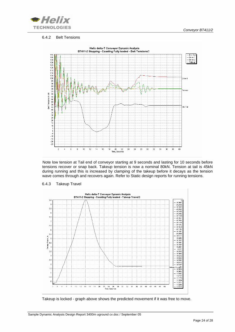
6.4.2 Belt Tensions
Note low tension at Tail end of conveyor starting at 9 seconds and lasting for 10 seconds before tensions recover or snap back. Takeup tension is now a nominal 80kN. Tension at tail is 45kN during running and this is increased by clamping of the takeup before it decays as the tension wave comes through and recovers again. Refer to Static design reports for running tensions.
6.4.3 Takeup Travel
Takeup is locked - graph above shows the predicted movement if it was free to move.
Conveyor BT411/2
Sample Dynamic Analysis Design Report 3400m uground cv.doc / September 05
Page 25 of 28
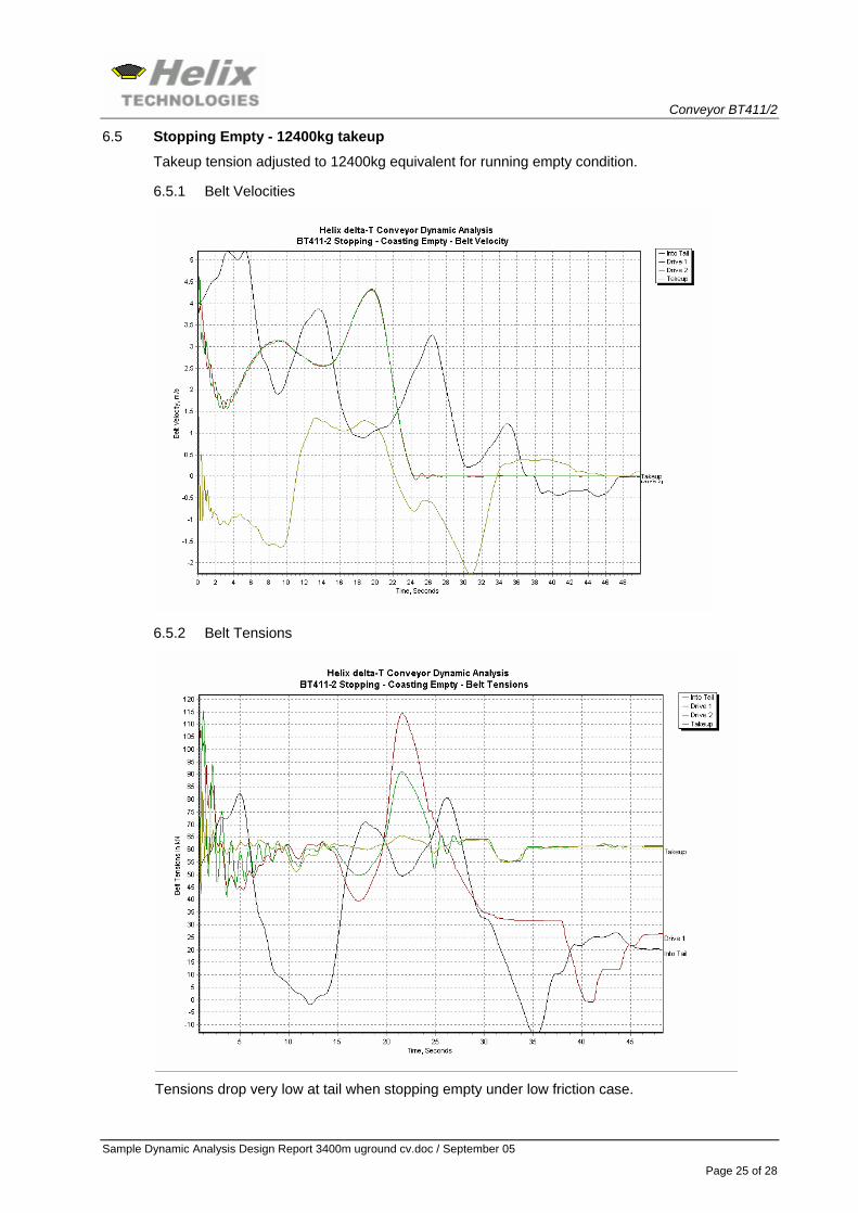
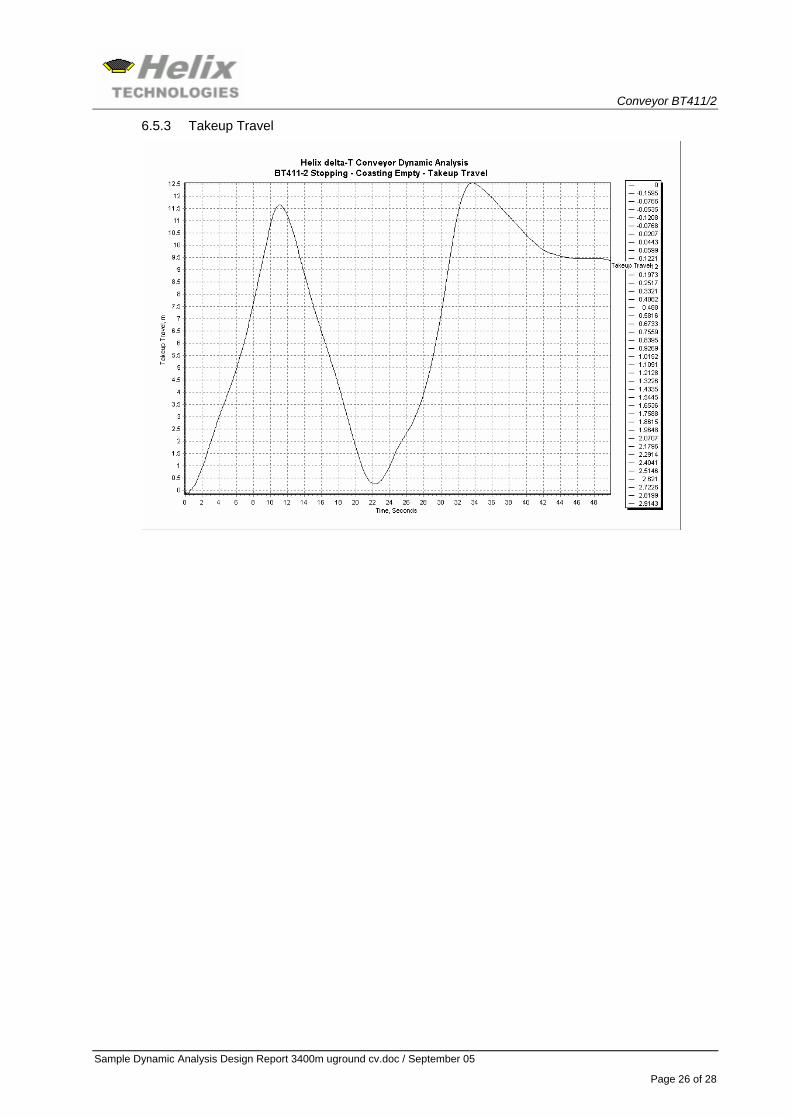
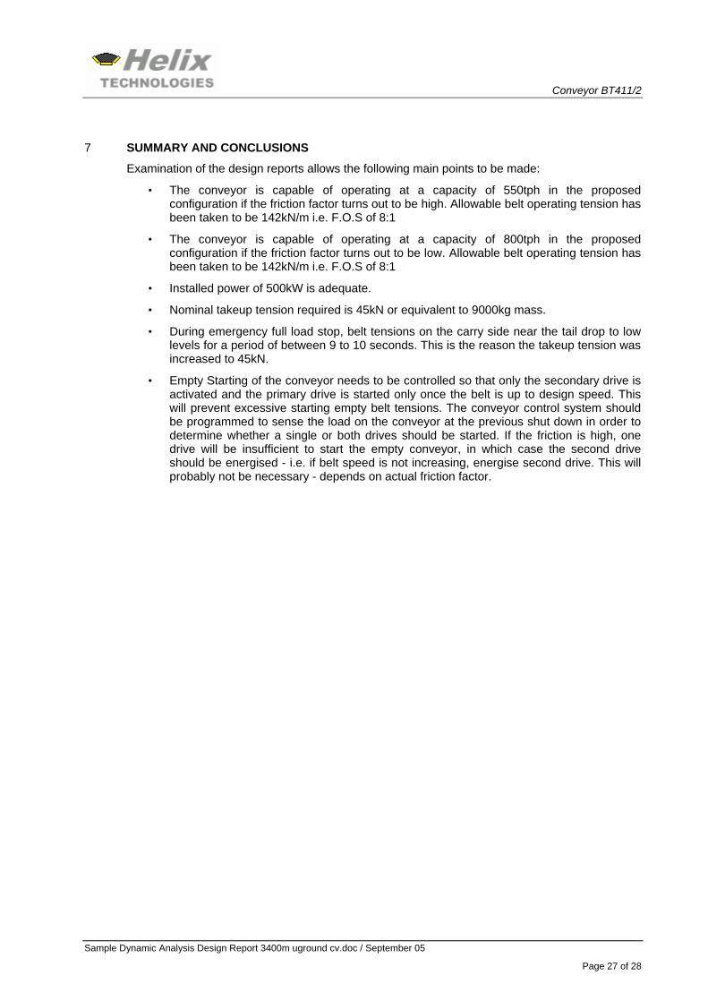
6.5 Stopping Empty - 12400kg takeup
Takeup tension adjusted to 12400kg equivalent for running empty condition.
6.5.1 Belt Velocities
6.5.2 Belt Tensions
Tensions drop very low at tail when stopping empty under low friction case.
Conveyor BT411/2
Sample Dynamic Analysis Design Report 3400m uground cv.doc / September 05
Page 26 of 28
6.5.3 Takeup Travel
Conveyor BT411/2
Sample Dynamic Analysis Design Report 3400m uground cv.doc / September 05
Page 27 of 28
7 SUMMARY AND CONCLUSIONS
Examination of the design reports allows the following main points to be made:
• The conveyor is capable of operating at a capacity of 550tph in the proposed configuration if the friction factor turns out to be high. Allowable belt operating tension has been taken to be 142kN/m i.e. F.O.S of 8:1
• The conveyor is capable of operating at a capacity of 800tph in the proposed configuration if the friction factor turns out to be low. Allowable belt operating tension has been taken to be 142kN/m i.e. F.O.S of 8:1
• Installed power of 500kW is adequate.
• Nominal takeup tension required is 45kN or equivalent to 9000kg mass.
• During emergency full load stop, belt tensions on the carry side near the tail drop to low levels for a period of between 9 to 10 seconds. This is the reason the takeup tension was increased to 45kN.
• Empty Starting of the conveyor needs to be controlled so that only the secondary drive is activated and the primary drive is started only once the belt is up to design speed. This will prevent excessive starting empty belt tensions. The conveyor control system should be programmed to sense the load on the conveyor at the previous shut down in order to determine whether a single or both drives should be started. If the friction is high, one drive will be insufficient to start the empty conveyor, in which case the second drive should be energised - i.e. if belt speed is not increasing, energise second drive. This will probably not be necessary - depends on actual friction factor.
Conveyor BT411/2
Sample Dynamic Analysis Design Report 3400m uground cv.doc / September 05
Page 28 of 28
8 APPENDICES
The following files in electronic file format make up the appendices to this report.
8.1 Bt411-2 Static Design Reports high friction.pdf
This report shows all the main input data for the conveyor as well as the 'rigid body' or 'static' design reports for the high friction factor case.
8.2 Bt411-2 Static Design Reports low friction.pdf
This report shows all the main input data for the conveyor as well as the 'rigid body' or 'static' design reports for the low friction factor case.
8.3 Bt411-2 Dynamics Starting Full High Friction.pdf
8.4 Bt411-2 Dynamics Starting Full Low Friction.pdf
8.5 Bt411-2 Dynamics Starting Empty High Friction 2 drives.pdf
8.6 Bt411-2 Dynamics Starting Empty High Friction 1 drive.pdf
8.7 Bt411-2 Dynamics Starting Empty Low Friction 2 drives.pdf
8.8 Bt411-2 Dynamics Starting Empty Low Friction 1 drives.pdf
8.9 Bt411-2 Dynamics Stopping Full High Friction takeup locked.pdf
8.10 Bt411-2 Dynamics Stopping Full Low Friction takeup locked.pdf
8.11 Bt411-2 Dynamics Stopping Empty High Friction takeup locked.pdf
8.12 Bt411-2 Dynamics Stopping Empty Low Friction takeup locked.pdf