Embed Size (px)
DESCRIPTION
Calculation for Material Handling System Design
Citation preview
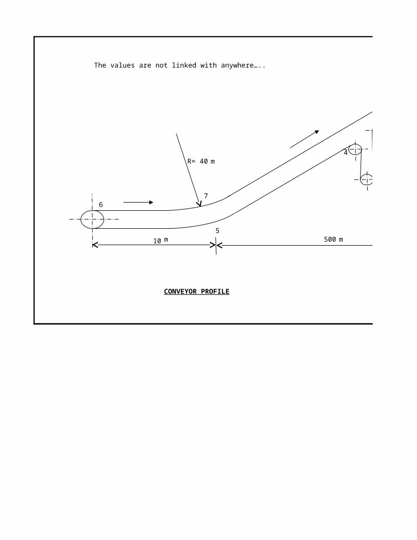
The values are not linked with anywhere…..
2
4R= 40 m
3
76
510 m 500 m
CONVEYOR PROFILE
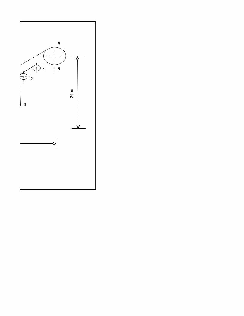
8
1 9
m2
0
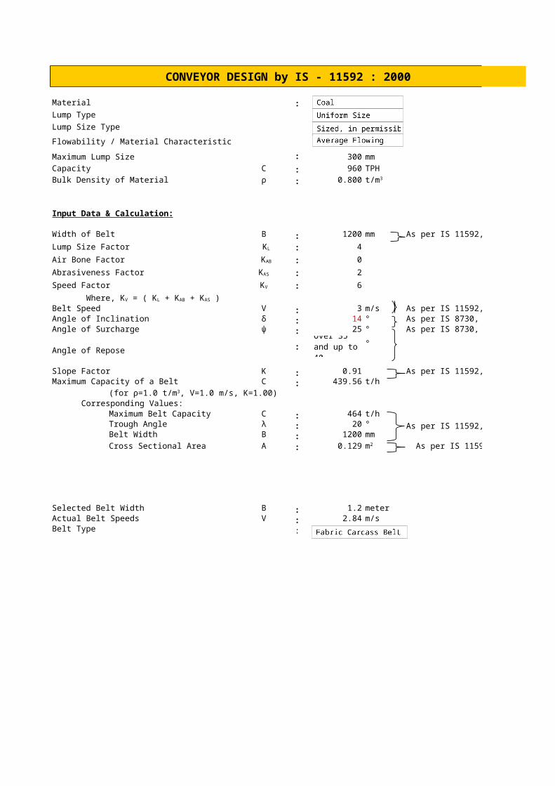
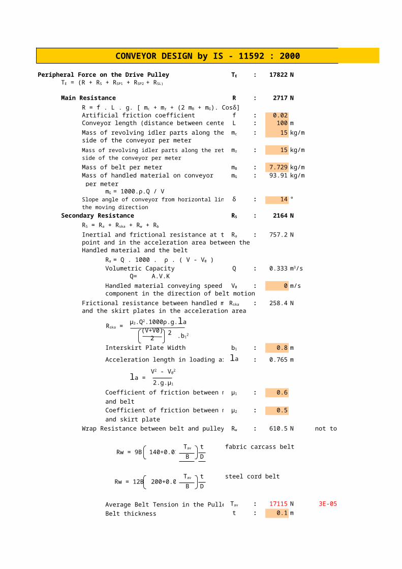
CONVEYOR DESIGN by IS - 11592 : 2000
Material : Bottom Ash
Lump Type
Lump Size Type
Flowability / Material Characteristic
Maximum Lump Size : 300 mm
Capacity C : 960 TPH
Bulk Density of Material ρ : 0.800
Input Data & Calculation:
Width of Belt B : 1200 mm As per IS 11592, Table 3
Lump Size Factor : 4
Air Bone Factor : 0
Abrasiveness Factor : 2
Speed Factor : 6
Belt Speed V : 3 m/s As per IS 11592, Table 6Angle of Inclination δ : 14 ° As per IS 8730, Table 3Angle of Surcharge ψ : 25 ° As per IS 8730, Table1
Angle of Repose: °
Slope Factor K : 0.91 As per IS 11592, Table 9Maximum Capacity of a Belt C : 439.56 t/h
Corresponding Values:Maximum Belt Capacity C : 464 t/hTrough Angle λ : 20 ° As per IS 11592, Table 10Belt Width B : 1200 mm
Cross Sectional Area A : 0.129 As per IS 11592, Table 7
Selected Belt Width B : 1.2 meter Actual Belt Speeds V : 2.84 m/sBelt Type :
t/m3
KL
KAB
KAS
KV
Where, KV = ( KL + KAB + KAS )
Over 35 and up to 40
(for ρ=1.0 t/m3, V=1.0 m/s, K=1.00)
m2
CONVEYOR DESIGN by IS - 11592 : 2000
Peripheral Force on the Drive Pulley : 17822 N
Main Resistance R : 2717 N
Artificial friction coefficient f : 0.02Conveyor length (distance between centers) L : 100 m
Mass of revolving idler parts along the carrying : 15 kg/mside of the conveyor per meter
Mass of revolving idler parts along the return : 15 kg/mside of the conveyor per meter
Mass of belt per meter : 7.7285 kg/mMass of handled material on conveyor : 93.912 kg/m per meter
Slope angle of conveyor from horizontal line in δ : 14 °the moving direction
Secondary Resistance : 2164 N
Inertial and frictional resistance at the loading : 757.21 Npoint and in the acceleration area between theHandled material and the belt
Volumetric Capacity Q : 0.3333Q= A.V.K
Handled material conveying speed : 0 m/scomponent in the direction of belt motion
Frictional resistance between handled material : 258.38 Nand the skirt plates in the acceleration area
(V+V0)2
Interskirt Plate Width : 0.8 m
Acceleration length in loading area : 0.7648 m
Coefficient of friction between material : 0.6
and belt
Coefficient of friction between material : 0.5
and skirt plate
Wrap Resistance between belt and pulley : 610.47 N not to be calculated for drive pulley
Rw = 9B 140+0.01.t for fabric carcass belt
B D
Rw = 12B 200+0.01.t for steel cord belt
B D
Average Belt Tension in the Pulley : 17115 N 3E-05
Belt thickness t : 0.1 m
TE
TE = (R + RS + RSP1 + RSP2 + RSL)
R = f . L . g. [ mc + mr + (2 mB + mG). Cosδ]
mc
mr
mB
mG
mG = 1000.ρ.Q / V
RS
RS = Ra + Rska + Rw + Rb
Ra
Ra = Q . 1000 . ρ . ( V - V0 )
m3/s
V0
Rska
Rska = μ2.Q2.1000ρ.g.la
.b12
b1
la
la = V2 - V0
2
2.g.μ1
μ1
μ2
Rw
Tav
Tav
Tav
2
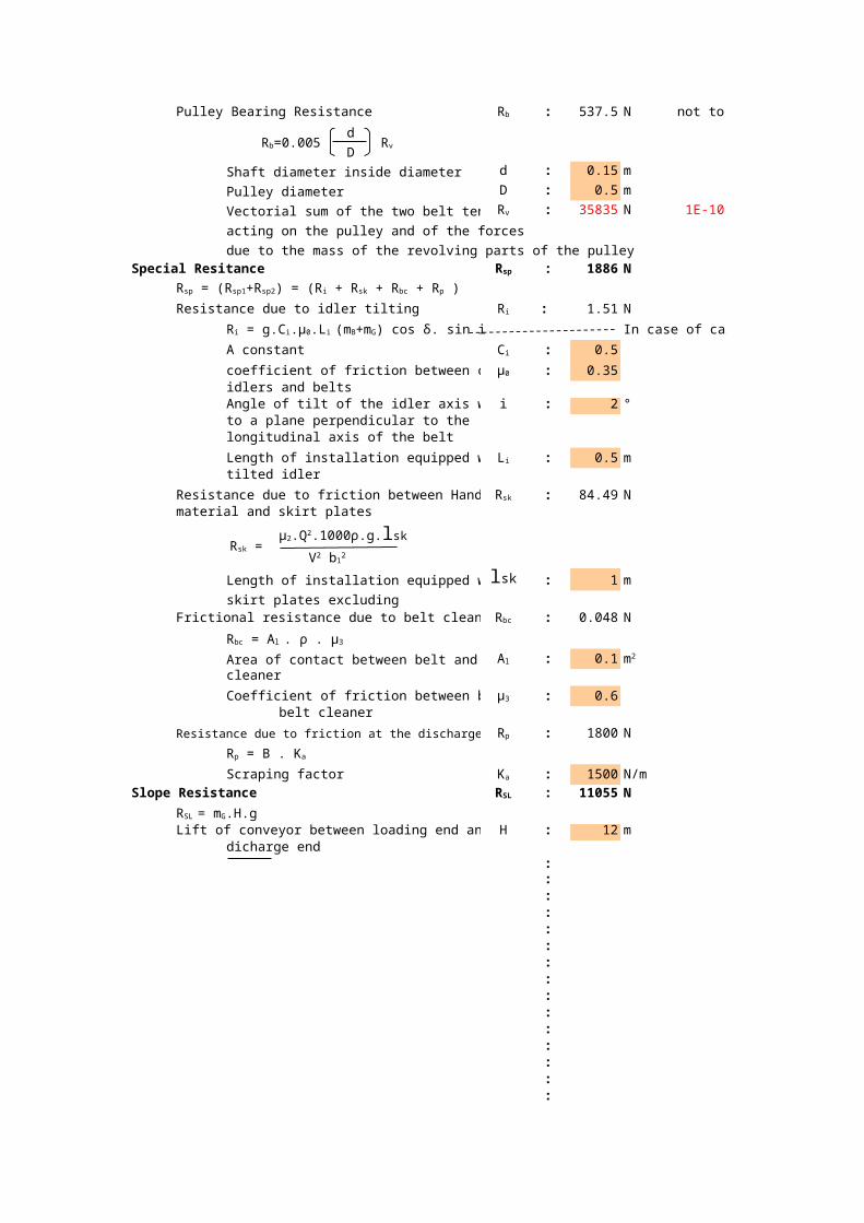
Pulley Bearing Resistance : 537.53 N not to be calculated for driving pulley
d
D
Shaft diameter inside diameter d : 0.15 m
Pulley diameter D : 0.5 m
Vectorial sum of the two belt tensions : 35835 N 1E-10
acting on the pulley and of the forces
due to the mass of the revolving parts of the pulley
Special Resitance : 1886 N
Resistance due to idler tilting : 1.5099 N
In case of carrying idlers equipped with three equal length rollers
A constant : 0.5
coefficient of friction between carrying : 0.35idlers and beltsAngle of tilt of the idler axis with respect i : 2 °to a plane perpendicular to the longitudinal axis of the belt
Length of installation equipped with : 0.5 mtilted idler
Resistance due to friction between Handled : 84.491 Nmaterial and skirt plates
Length of installation equipped with : 1 mskirt plates excluding
Frictional resistance due to belt cleaners : 0.048 N
Area of contact between belt and belt : 0.1cleaner
Coefficient of friction between belt and : 0.6belt cleaner
Resistance due to friction at the discharge plough : 1800 N
Scraping factor : 1500 N/m
Slope Resistance : 11055 N
Lift of conveyor between loading end and H : 12 mdicharge end
:::::::::::::::
Rb
Rb=0.005 Rv
Rv
Rsp
Rsp = (Rsp1+Rsp2) = (Ri + Rsk + Rbc + Rp )
Ri
Ri = g.Ci.μ0.Li (mB+mG) cos δ. sin i
Ci
μ0
Li
Rsk
Rsk = μ2.Q2.1000ρ.g.lsk
V2 b12
lsk
Rbc
Rbc = Al . ρ . μ3
Al m2
μ3
Rp
Rp = B . Ka
Ka
RSL
RSL = mG.H.g
::

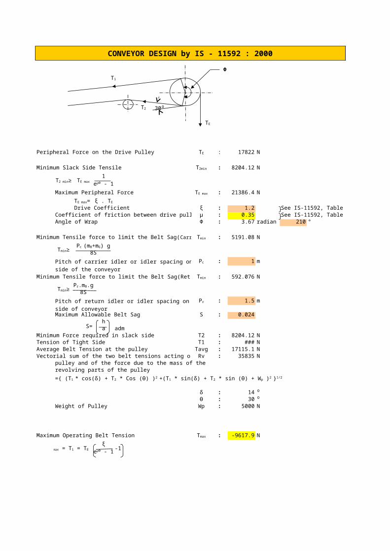
CONVEYOR DESIGN by IS - 11592 : 2000
Φ
Peripheral Force on the Drive Pulley : 17822 N
Minimum Slack Side Tensile : 8204.12 N
1
Maximum Peripheral Force : 21386.38 N
Drive Coefficient ξ : 1.2 See IS-11592, Table 15Coefficient of friction between drive pulley and belt μ : 0.35 See IS-11592, Table 16Angle of Wrap Φ : 3.67 radian 210 °
: 5191.077 N
8S
Pitch of carrier idler or idler spacing on carrying : 1 mside of the conveyor
Minimum Tensile force to limit the Belt Sag(Return Side) : 592.0756 N
8S
Pitch of return idler or idler spacing on return : 1.5 mside of conveyorMaximum Allowable Belt Sag S : 0.024
S=ha adm
Minimum Force required in slack side T2 : 8204.12 NTension of Tight Side T1 : 26026.11 NAverage Belt Tension at the pulley Tavg : 17115.11 NVectorial sum of the two belt tensions acting on the Rv : 35835 N
pulley and of the force due to the mass of therevolving parts of the pulley
δ : 14 ⁰Ѳ : 30 ⁰
Weight of Pulley Wp : 5000 N
Maximum Operating Belt Tension : -9617.87 N
ξ-1
T1
T2 30⁰
TE
TE
T2min
T2 min≥ TE maxeμΦ - 1
TE max
TE max= ξ . TE
Minimum Tensile force to limit the Belt Sag(Carrying Side) Tmin
Tmin≥Pc (mB+mG) g
Pc
Tmin
Tmin≥Pr.mB.g
Pr
={ (T1 * cos(δ) + T2 * Cos (Ѳ) )2 +(T1 * sin(δ) + T2 * sin (Ѳ) + Wp )2 }1/2
Tmax
Tmax = T1 = TE eμΦ - 1

:

Table 3: Maximum Lumps Sizes in relationto Belt Width
Belt WidthMaximum Lump Size
Uniform Size Unsized 300 75 100 1400 75 100 2450 75 125 3500 100 150 4600 125 200 5650 125 230 6750 180 300 7800 180 330 8900 200 380 9
1000 260 430 101050 280 460 111200 360 530 121350 380 660 131400 380 680 141500 410 750 151600 410 800 161800 460 900 172000 500 1020 18
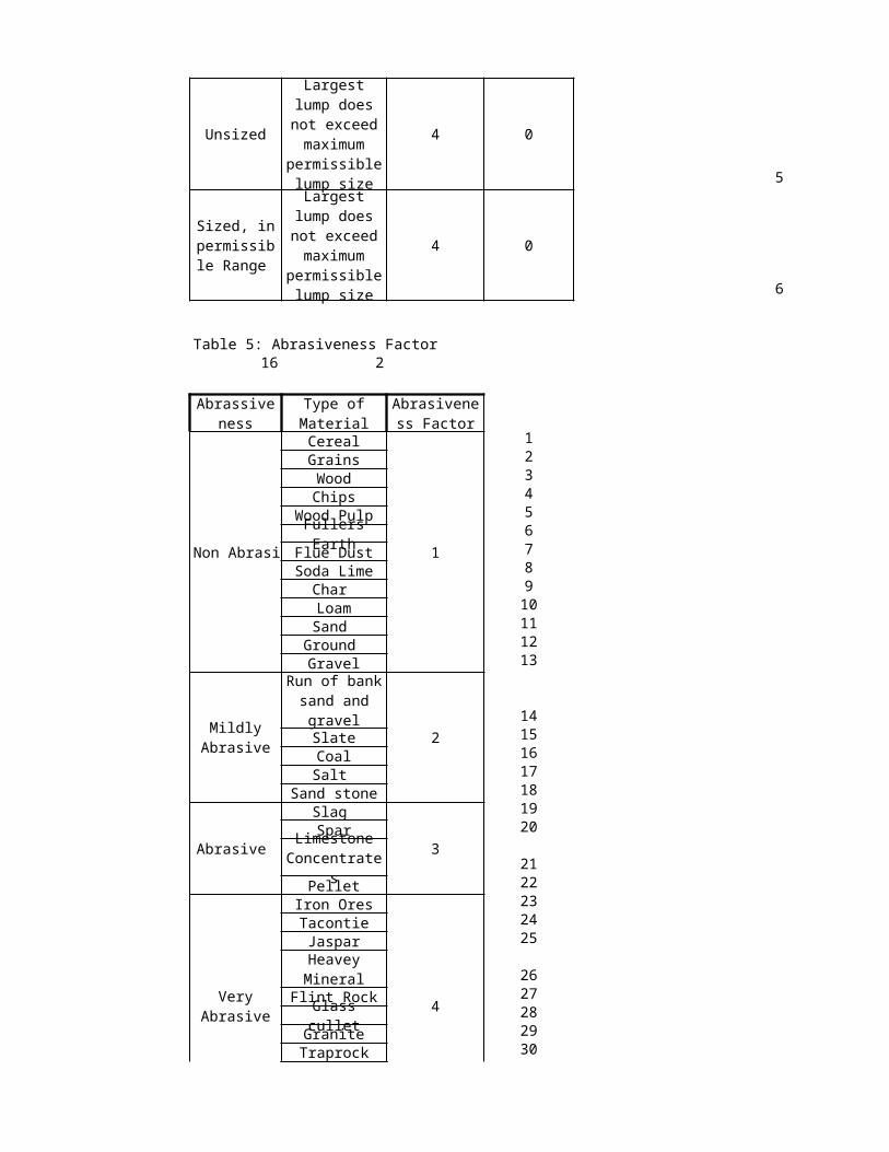
Table 4: Lump Size Factor6 4 0
Material Lump Size
<10 mm 0 4 1Granular <25mm 1 0 2
2 0
3
3 0
4
Lump Size Factor
Air Bone Factor
Fine Grain to dust
Sized and Unsized
<20 percent of maximum permissible lump size
Sized, <60% in
permissible Range
Quantity of largest Lump is <60 percent of maximum permissible lump size
Unsized 4 0
5
4 0
6
Table 5: Abrasiveness Factor16 2
Non Abrasiv
Cereal
1
1Grains 2Wood 3Chips 4
Wood Pulp 5Fullers Earth 6
Flue Dust 7Soda Lime 8
Char 9Loam 10Sand 11
Ground 12Gravel 13
214
Slate 15Coal 16Salt 17
Sand stone 18
Abrasive
Slag
3
19Spar 20
21Pellet 22
Iron Ores
4
23Tacontie 24Jaspar 25
26Flint Rock 27
Glass cullet 28Granite 29
Traprock 30
Largest lump does not exceed
maximum permissible lump size
Sized, in permissible
Range
Largest lump does not exceed
maximum permissible lump size
Abrassiveness
Type of Material
Abrasiveness Factor
Mildly Abrasive
Run of bank sand and
gravel
Limestone Concentrates
Very Abrasive
Heavey Mineral

Pyrites
4
31Sinter 32Coke 33
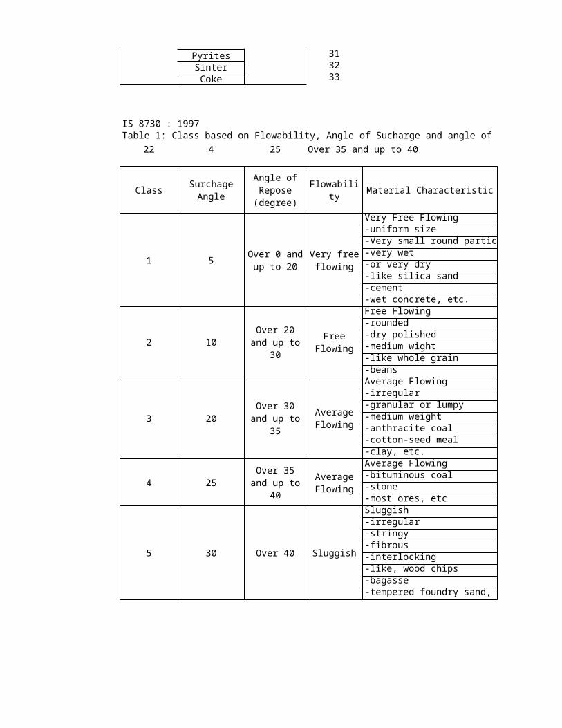
IS 8730 : 1997Table 1: Class based on Flowability, Angle of Sucharge and angle of repose
22 4 25 Over 35 and up to 40
Class Flowability Material Characteristic
1 5
Very Free Flowing-uniform size-Very small round particle-very wet-or very dry-like silica sand-cement-wet concrete, etc.
2 10
Free Flowing-rounded-dry polished -medium wight-like whole grain-beans
3 20
Average Flowing-irregular-granular or lumpy-medium weight-anthracite coal-cotton-seed meal-clay, etc.
4 25
Average Flowing-bituminous coal-stone-most ores, etc
5 30 Over 40 Sluggish
Sluggish-irregular-stringy-fibrous-interlocking-like, wood chips-bagasse-tempered foundry sand, etc.
Very Abrasive
Surchage Angle
Angle of Repose (degree)
Over 0 and up to 20
Very free flowing
Over 20 and up to 30
Free Flowing
Over 30 and up to 35
Average Flowing
Over 35 and up to 40
Average Flowing
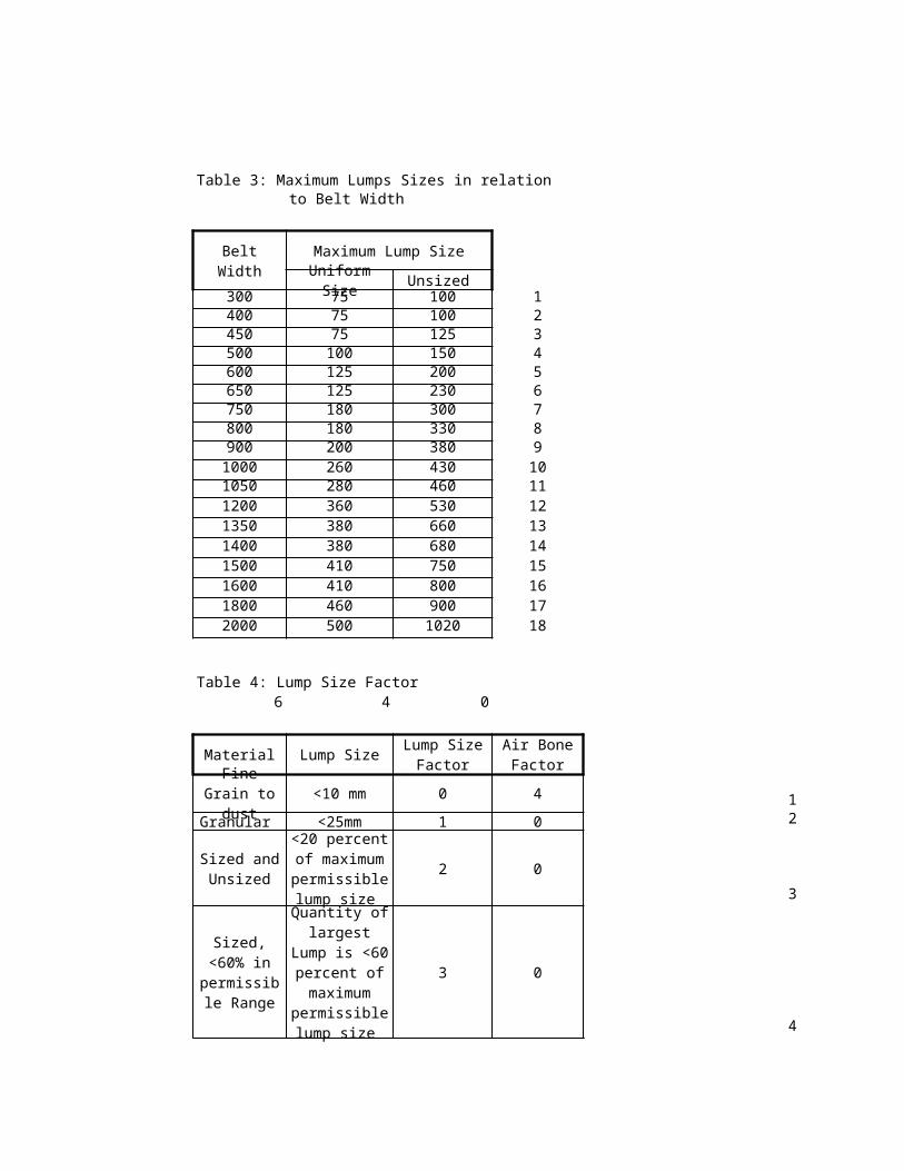
Table 6: Maximum Recommended Belt Speed (m/s)
Belt Width in mmup to 500 600 to 650 750 to 800 950 to 1050 1200 to 2000
1 2.5 3 3.5 4 4.52 2.3 2.75 3.2 3.65 4.123 2 2.38 2.75 3.15 3.554 2 2.38 2.75 3.15 3.555 1.65 2 2.35 2.65 36 1.65 2 2.35 2.65 37 1.45 1.75 2.05 2.35 2.628 1.45 1.75 2.05 2.35 2.62
Lump SizeLump Type 300 280 0.93
11 1050 1200Uniform Size 1 300 300 1.0Unsized 7 750 800
Belt Width 1200Speed Factor: 6Velocity 3 For belt size above 2000mm 2.5m/s
velocity has been considered.
Belt TypeFabric Carcass Belt 1Steel Cord Belt
Speed Factor
123456789
101112131415161718192021222324252627282930313233
.
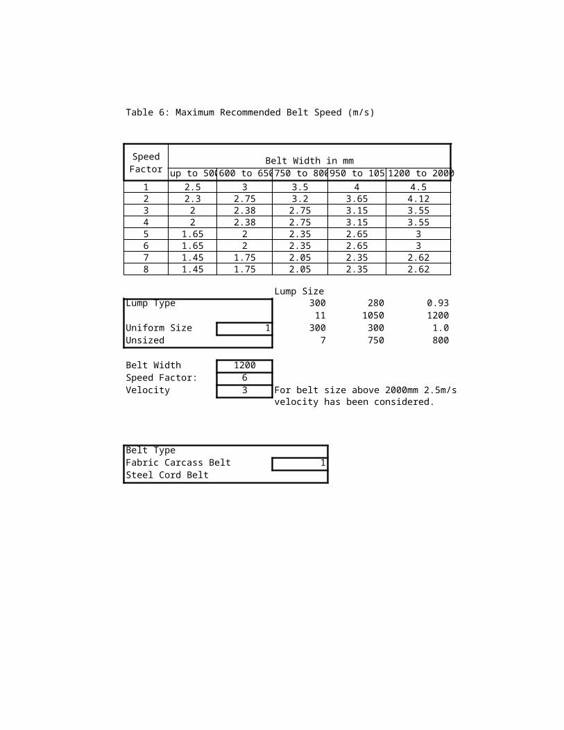
Table 7: Maximum Section of the Handled Maaterial in M2 for Triple Roller Troughed Belt1200 25 20 0.129
Trough Angle in Degree
20 25 30 35 40 45500 0 0.009 0.012 0.013 0.015 0.017 0.018
10 0.014 0.016 0.18 0.019 0.021 0.02220 0.018 0.02 0.022 0.023 0.024 0.02530 0.023 0.025 0.026 0.027 0.028 0.029
650 0 0.018 0.022 0.026 0.029 0.032 0.03410 0.026 0.029 0.033 0.036 0.038 0.0420 0.034 0.037 0.04 0.043 0.045 0.04630 0.042 0.045 0.048 0.05 0.052 0.053
800 0 0.027 0.034 0.04 0.045 0.05 0.05410 0.04 0.046 0.051 0.056 0.06 0.06320 0.053 0.059 0.063 0.067 0.071 0.07330 0.067 0.072 0.076 0.079 0.082 0.084
1000 0 0.047 0.058 0.067 0.076 0.083 0.08910 0.067 0.077 0.085 0.093 0.099 0.10520 0.087 0.096 0.104 0.111 0.116 0.1230 0.109 0.117 0.134 0.129 0.134 0.136
1200 0 0.07 0.085 0.099 0.112 0.123 0.13210 0.098 0.113 0.126 0.137 0.146 0.15420 0.129 0.142 0.153 0.163 0.171 0.17630 0.16 0.172 0.182 0.19 0.196 0.2
1400 0 0.098 0.12 0.139 0.157 0.171 0.18410 0.138 0.158 0.175 0.191 0.204 0.21420 0.179 0.197 0.213 0.22 0.237 0.24530 0.221 0.238 0.253 0.264 0.272 0.277
1600 0 0.13 0.159 0.185 0.208 0.228 0.244
10 0.182 0.209 0.233 0.253 0.27 0.28320 0.236 0.261 0.282 0.3 0.314 0.324
30 0.293 0.315 0.334 0.349 0.36 0.366
1800 0 0.167 0.203 0.237 0.266 0.292 0.313
Belt Width (in mm)
Surcharge Angle
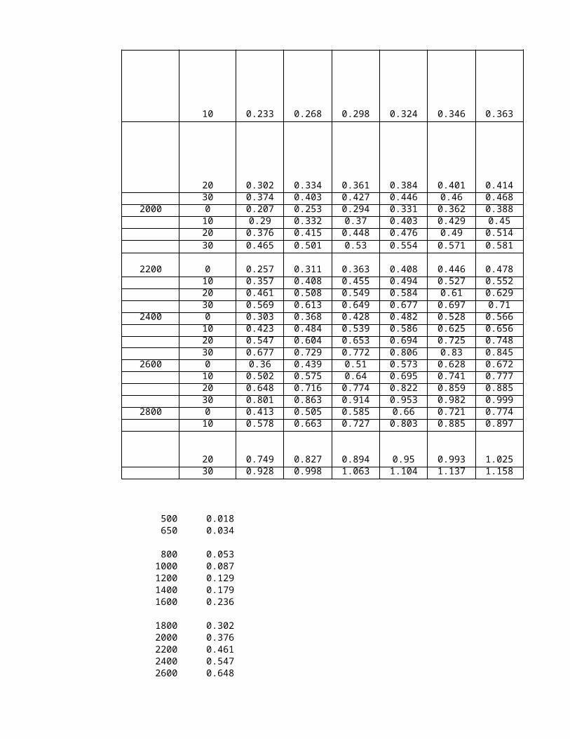
10 0.233 0.268 0.298 0.324 0.346 0.363
20 0.302 0.334 0.361 0.384 0.401 0.41430 0.374 0.403 0.427 0.446 0.46 0.468
2000 0 0.207 0.253 0.294 0.331 0.362 0.38810 0.29 0.332 0.37 0.403 0.429 0.4520 0.376 0.415 0.448 0.476 0.49 0.51430 0.465 0.501 0.53 0.554 0.571 0.581
2200 0 0.257 0.311 0.363 0.408 0.446 0.47810 0.357 0.408 0.455 0.494 0.527 0.55220 0.461 0.508 0.549 0.584 0.61 0.62930 0.569 0.613 0.649 0.677 0.697 0.71
2400 0 0.303 0.368 0.428 0.482 0.528 0.56610 0.423 0.484 0.539 0.586 0.625 0.65620 0.547 0.604 0.653 0.694 0.725 0.74830 0.677 0.729 0.772 0.806 0.83 0.845
2600 0 0.36 0.439 0.51 0.573 0.628 0.67210 0.502 0.575 0.64 0.695 0.741 0.77720 0.648 0.716 0.774 0.822 0.859 0.88530 0.801 0.863 0.914 0.953 0.982 0.999
2800 0 0.413 0.505 0.585 0.66 0.721 0.77410 0.578 0.663 0.727 0.803 0.885 0.897
20 0.749 0.827 0.894 0.95 0.993 1.02530 0.928 0.998 1.063 1.104 1.137 1.158
500 0.018650 0.034
800 0.0531000 0.0871200 0.1291400 0.1791600 0.236
1800 0.3022000 0.3762200 0.4612400 0.5472600 0.648

2800 0.749
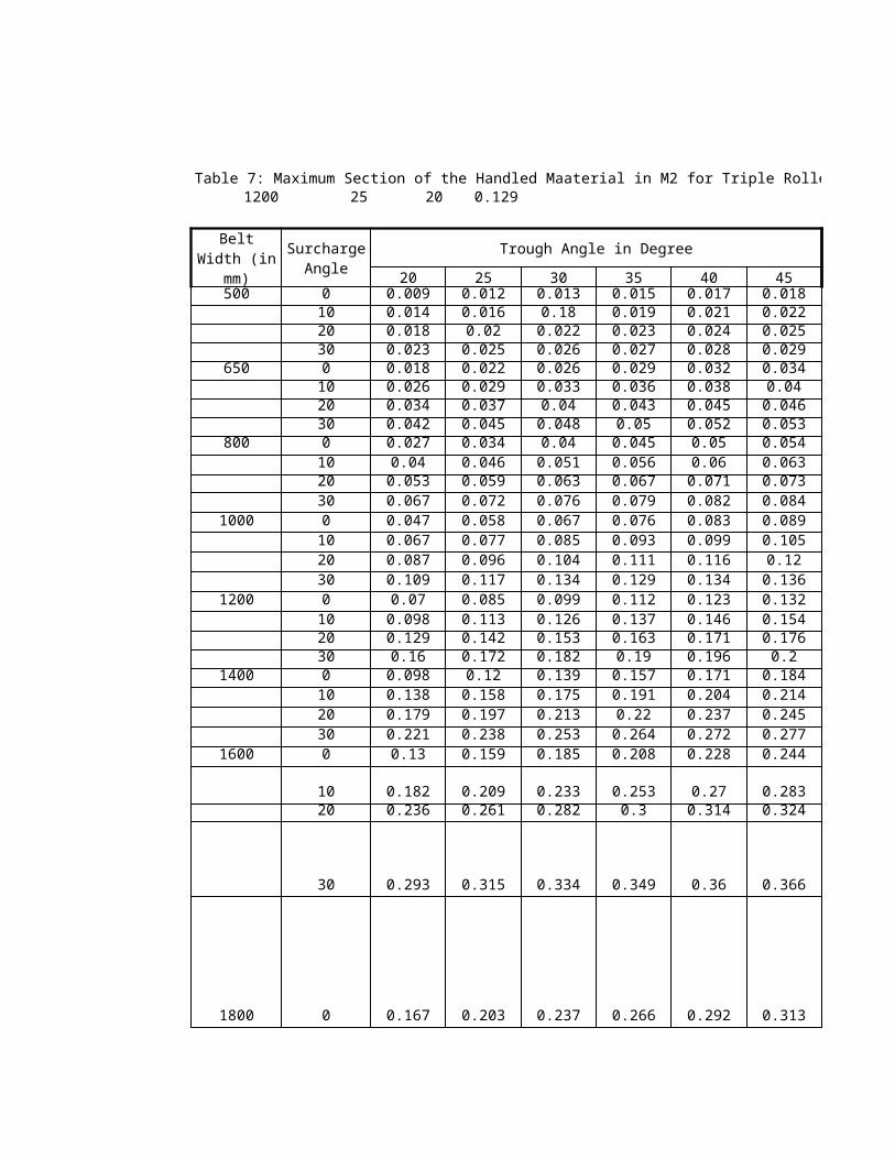
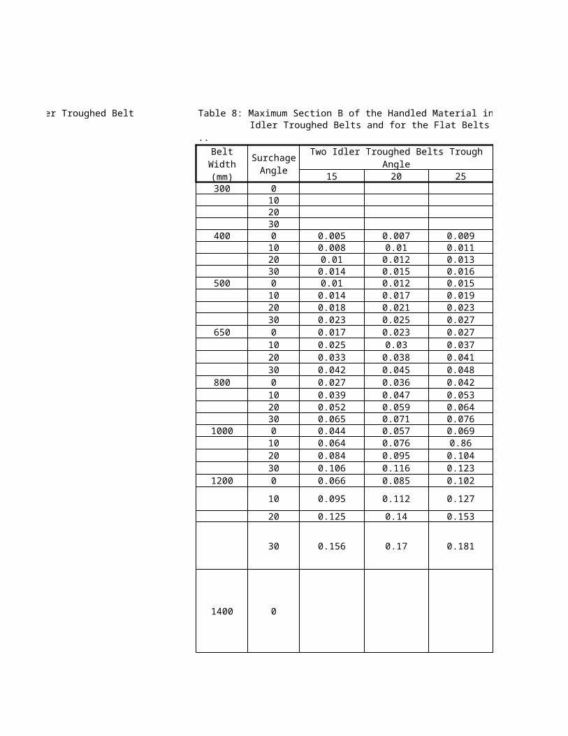
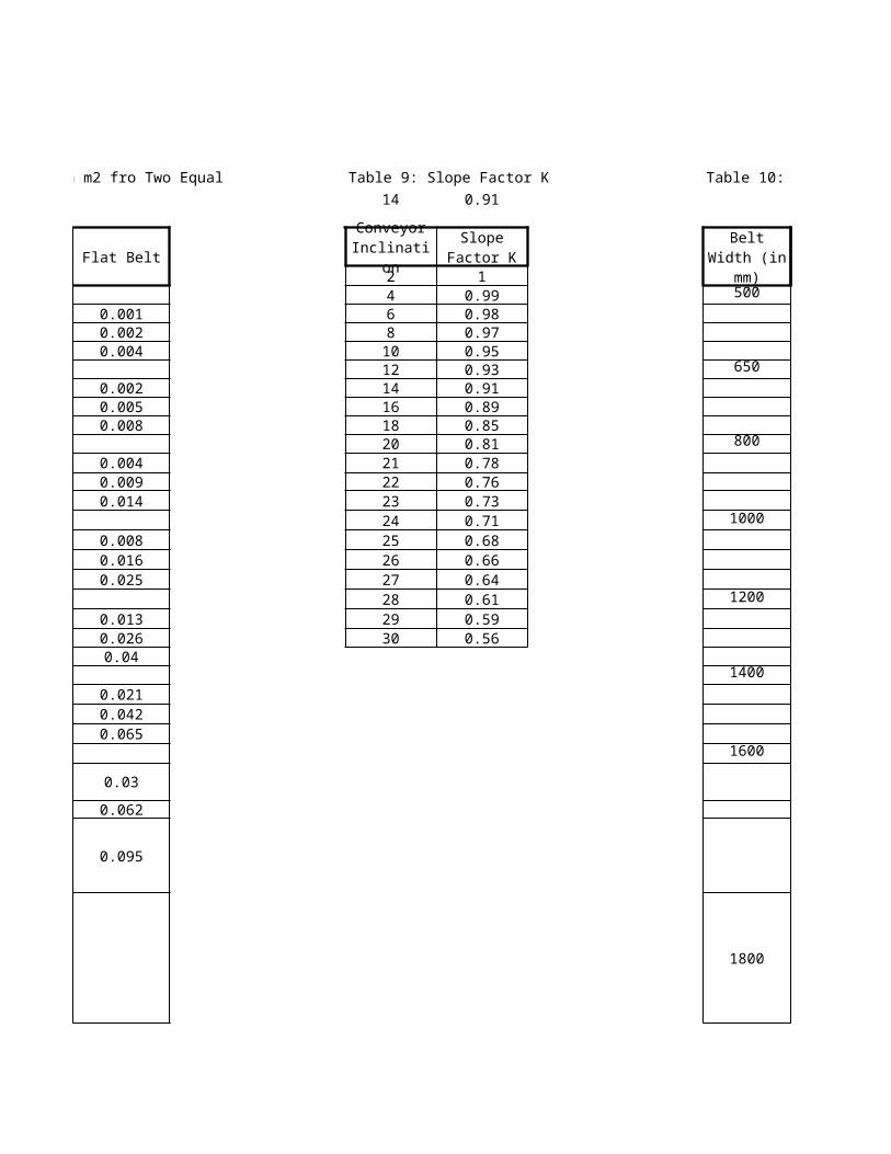
Table 8: Maximum Section B of the Handled Material in m2 fro Two Equal Idler Troughed Belts and for the Flat Belts
..
Two Idler Troughed Belts Trough AngleFlat Belt
15 20 25300 0
10 0.00120 0.00230 0.004
400 0 0.005 0.007 0.00910 0.008 0.01 0.011 0.00220 0.01 0.012 0.013 0.00530 0.014 0.015 0.016 0.008
500 0 0.01 0.012 0.01510 0.014 0.017 0.019 0.00420 0.018 0.021 0.023 0.00930 0.023 0.025 0.027 0.014
650 0 0.017 0.023 0.02710 0.025 0.03 0.037 0.00820 0.033 0.038 0.041 0.01630 0.042 0.045 0.048 0.025
800 0 0.027 0.036 0.04210 0.039 0.047 0.053 0.01320 0.052 0.059 0.064 0.02630 0.065 0.071 0.076 0.04
1000 0 0.044 0.057 0.06910 0.064 0.076 0.86 0.02120 0.084 0.095 0.104 0.04230 0.106 0.116 0.123 0.065
1200 0 0.066 0.085 0.102
10 0.095 0.112 0.127 0.03
20 0.125 0.14 0.153 0.062
30 0.156 0.17 0.181 0.095
1400 0
Belt Width (mm)
Surchage Angle
10 0.042
20 0.086
30 0.1321600 0
10 0.5620 0.11430 0.175
Table 9: Slope Factor K Table 10: Maximum Capacity of a Belt Conveyor in tonnes/hour14 0.91 25 439.56 1200
Trough Angle in Degree
2 1 20 254 0.99 500 0 35 436 0.98 10 51 588 0.97 20 67 74
10 0.95 30 84 9012 0.93 650 0 56 8014 0.91 10 94 10716 0.89 20 123 13518 0.85 30 153 16520 0.81 800 0 100 123
21 0.78 10 145 16822 0.76 20 192 212
23 0.73 30 241 260
24 0.71 1000 0 172 209
25 0.68 10 242 277
26 0.66 20 315 348
27 0.64 30 392 421
28 0.61 1200 0 252 307
29 0.59 10 355 40730 0.56 20 464 511
30 576 6191400 0 352 432
10 497 56920 644 70930 795 857
1600 0 468 572
10 655 75220 849 939
30 1054 1134
1800
0
601 731
Conveyor Inclination
Slope Factor K Belt Width
(in mm)Surcharge
Angle
10
839 965
20
1087 1202
30 1346 14512000 0 745 911
10 1044 119520 1359 149430 1674 1803
1 2500 0 67 74650 0 123 135800 0 192 212
1000 0 315 3481200 1 464 5111400 1 644 7091600 1 849 9391800 1 1087 12022000 #N/A #N/A #N/A
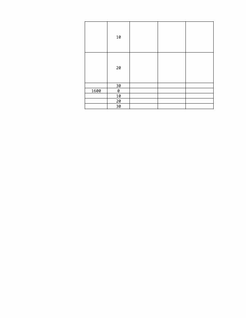
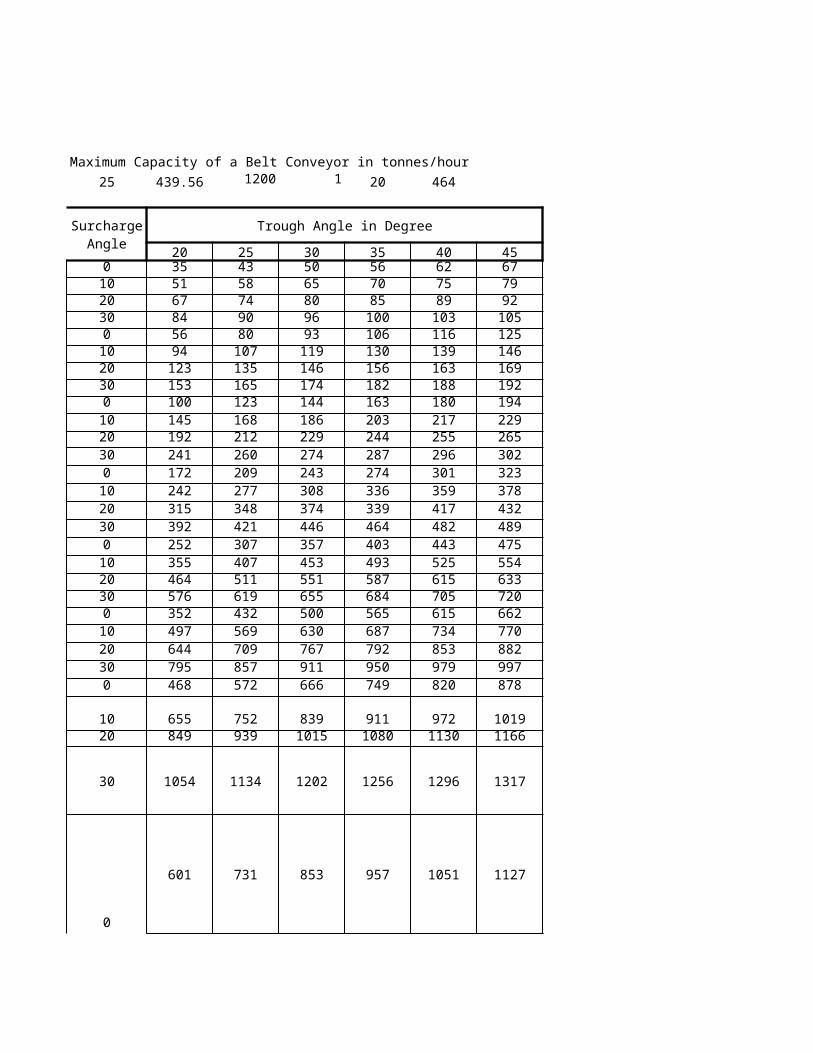
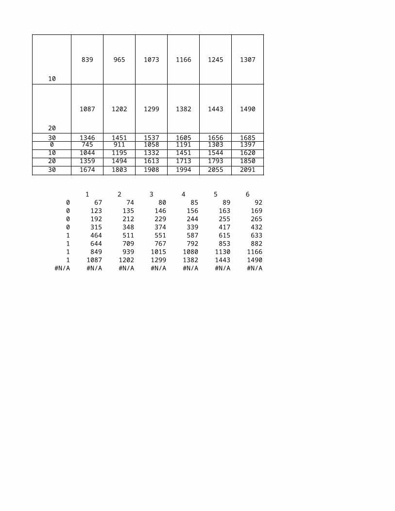
Table 10: Maximum Capacity of a Belt Conveyor in tonnes/hour Table 11: Mximum Capacity of a Belt Conveyor in tonnes/hours1 20 464
Trough Angle in Degree
30 35 40 45 1550 56 62 67 300 065 70 75 79 1080 85 89 92 2096 100 103 105 3093 106 116 125 400 0 21
119 130 139 146 10 30146 156 163 169 20 40174 182 188 192 30 50144 163 180 194 500 0 36186 203 217 229 10 53229 244 255 265 20 67274 287 296 302 30 84243 274 301 323 650 0 64308 336 359 378 10 96374 339 417 432 20 121446 464 482 489 30 151357 403 443 475 800 0 99453 493 525 554 10 143551 587 615 633 20 188655 684 705 720 30 236500 565 615 662 1000 0 161630 687 734 770 10 232767 792 853 882 20 304911 950 979 997 30 381666 749 820 878 1200 0 238
839 911 972 1019 10 342
1015 1080 1130 1166 20 450
1202 1256 1296 1317 30 561
853 957 1051 1127 1400 0
Belt Width (mm)
Surchage Angle
Two Idler Troughed Belts Trough Angle
1073 1166 1245 1307 10
1299 1382 1443 1490 20
1537 1605 1656 1685 301058 1191 1303 1397 1600 01332 1451 1544 1620 101613 1713 1793 1850 201908 1994 2055 2091 30
3 4 5 680 85 89 92
146 156 163 169229 244 255 265374 339 417 432551 587 615 633767 792 853 882
1015 1080 1130 11661299 1382 1443 1490#N/A #N/A #N/A #N/A
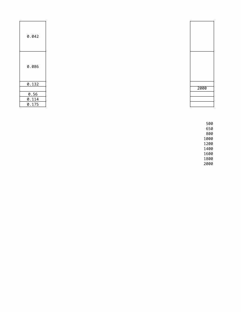
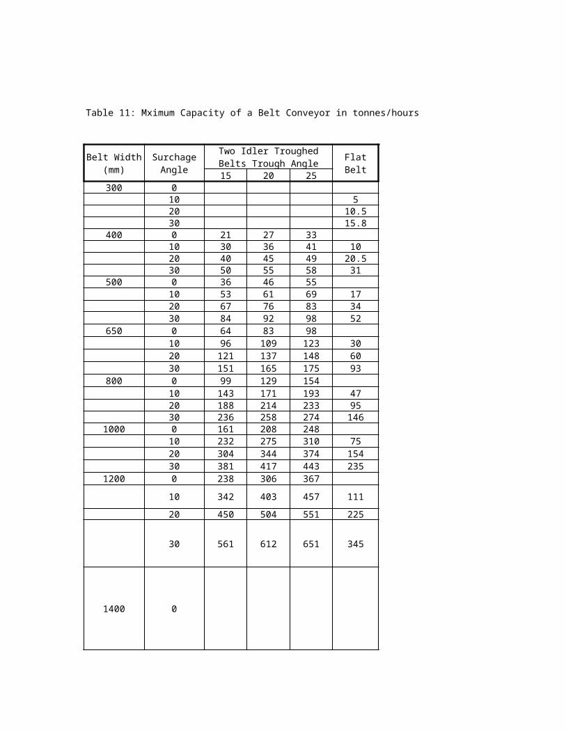
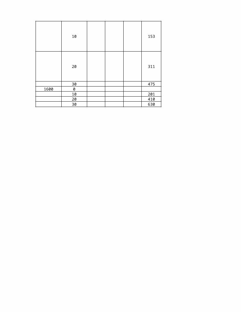
Table 11: Mximum Capacity of a Belt Conveyor in tonnes/hours
Flat Belt20 25
510.515.8
27 3336 41 1045 49 20.555 58 3146 5561 69 1776 83 3492 98 5283 98
109 123 30137 148 60165 175 93129 154171 193 47214 233 95258 274 146208 248275 310 75344 374 154417 443 235306 367
403 457 111
504 551 225
612 651 345
Two Idler Troughed Belts Trough Angle
153
311
475
201410630
…
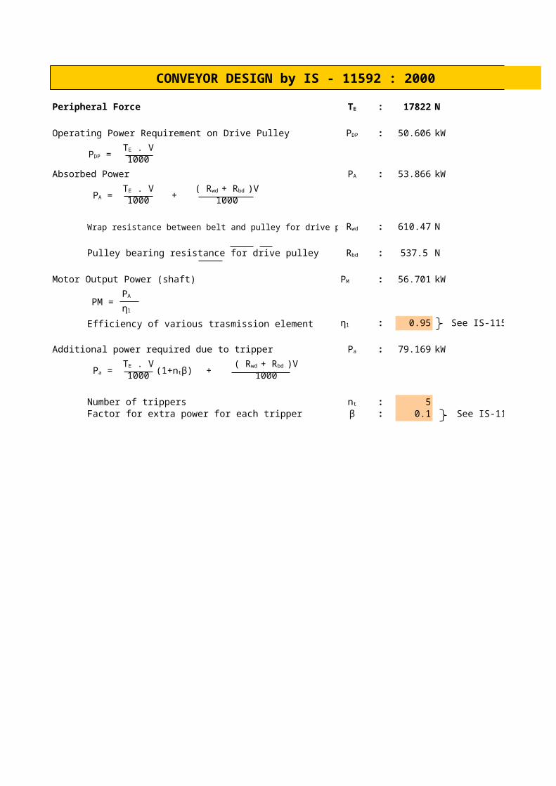
CONVEYOR DESIGN by IS - 11592 : 2000
Peripheral Force : 17822 N
Operating Power Requirement on Drive Pulley : 50.606 kW
1000
Absorbed Power : 53.866 kW
+1000 1000
Wrap resistance between belt and pulley for drive pulley : 610.47 N
Pulley bearing resistance for drive pulley : 537.5 N
Motor Output Power (shaft) : 56.701 kW
PM =
Efficiency of various trasmission element : 0.95 See IS-11592 table 12
Additional power required due to tripper : 79.169 kW
+1000 1000
Number of trippers : 5Factor for extra power for each tripper β : 0.1 See IS-11592 table 13or14
TE
PDP
PDP = TE . V
PA
PA = TE . V ( Rwd + Rbd )V
Rwd
Rbd
PM
PA
η1
η1
Pa
Pa = TE . V
(1+ntβ)( Rwd + Rbd )V
nt
CONVEYOR DESIGN by IS - 11592 : 2000
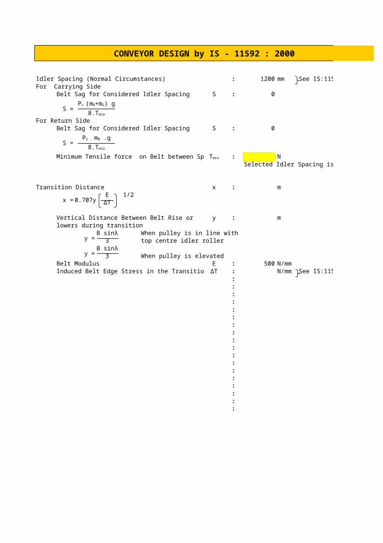
Idler Spacing (Normal Circumstances) : 1200 mm See IS:11592, Table 17For Carrying Side
Belt Sag for Considered Idler Spacing S : 0
S =
For Return SideBelt Sag for Considered Idler Spacing S : 0
S =
Minimum Tensile force on Belt between Spacing : NSelected Idler Spacing is Safe
Transition Distance x : m
x = 0.707yE 1/2
Vertical Distance Between Belt Rise or y : mlowers during transition
y =When pulley is in line with
3 top centre idler roller
y = 3 When pulley is elevatedBelt Modulus E : 500 N/mmInduced Belt Edge Stress in the Transition : N/mm See IS:11592, Table 18
::::::::::::::::::
Pc (mB+mG) g
8.Tmin
Pr . mB .g
8.Tmin
Tmin
ΔT
B sinλ
B sinλ
ΔT

CONVEYOR DESIGN by IS - 11592 : 2000
See IS:11592, Table 17
See IS:11592, Table 18
CONVEYOR DESIGN by IS - 11592 : 2000
Selection Of BeltFactor of Safety Factor of Safety: : 10Full Thickness Tensile Strength of Belt : -96178.6626 N
*Select the Belt Type
Selectecd Belt : Belt TypeBelt Thickness t : m
Grade of Cover Thickness : N17Conveyor Carrying Side Thickness : 2.5 mmBelting Pulley Side Thickness : 1.0 mmElevator Carrying Side Thickness : 1.5 mmBelting Pulley Side Thickness : 2.5 mm
:Diameter of Pulley D :
Driving Pulley and Pulley Exposed to high tension : mmSnub Pulley in the return run under lower tension : mmBend Pulley for a change of Direction of the belt : mm
of less then 30°::::::::::
See IS-1891 (Part-1) Annex A
See IS-1891(Part-1) Table 8 and IS
3181 for PVC Belt
Factor of Safety:Textile Belt Textile Belt: 9 to 12.5, Generally 10Steel Cord Belt Steel Cord Belt: 7 to 10, Generally 7
Belt TypeTextile Rubber Belt Textile Rubber: 1.0 to 3.0 mm M24PVC Belt PVC belt: 0.8 to 1.2 mm N17Steel Cord Belt Steel cord Belts: Min. 4.0mm N17 Synthetic
DETERMINATION OF CONVEYOR SECTIONAL AREA AS PER C.E.M.A
F B GA C a
bc
mf l r
ja a
DTYPICAL CONVEYOR CROSS-SECTION
= angle which the surface of the material assumes with the horizontal while the material is at rest on a moving conveyor belt
l = 0.371 x b + 0.25Cross-sectional area of material on conveyor , sq. in
BELT WIDTH a b A A Belt Bulk. Dnst. Capacity l l
mm in deg. deg. sq. ft sq.m Speed m/s Te/Hr. in mm
800 32 25 20 0.6728 0.063 0.84 800 151.2151 12.12 307.90
450 18 25 20 0.1881 0.017 2 800 100.6383 6.93 175.97
500 20 25 20 0.2391 0.022 1.2 800 76.7525 7.67 194.82
600 24 25 20 0.3593 0.033 2 800 192.2602 9.15 232.51
750 30 25 20 0.5853 0.054 2 800 313.2048 11.38 289.05
900 36 25 20 0.8661 0.08 2 800 463.4721 13.61 345.59
1000 40 25 20 1.0838 0.101 1.83 800 530.6457 15.09 383.29
1050 42 25 20 1.2017 0.112 2 800 643.0621 15.83 402.13
1200 48 25 20 1.5921 0.148 1.25 800 532.4842 18.06 458.67
1350 54 25 20 2.0373 0.189 2 800 1090.21 20.28 515.21
1500 60 25 20 2.5373 0.236 2 800 1357.768 22.51 571.75
1800 72 25 20 3.7017 0.344 2 800 1980.852 26.96 684.83
2100 84 25 20 5.0852 0.472 2 800 2721.226 31.41 797.92
2400 96 25 20 6.688 0.621 2 800 3578.892 35.87 911.00
NB : Results are verified against CEMA's Publication
l1
a = angle of surcharge , degrees
= 25 O for bituminous coal or ligniteb = angle of the idler roll , degreesb = width of belt , inchesStandard edge distance , c =0.055b + 0.9 , inches b = l + 2m + 2c m = 0.2595 x b -1.025
A = [ 0.371b + 0.25 + (0.2595b - 1.025) cos b ] x [ ( 0.2595 b -1.025 ) sin b ]
+ (π a/180 - sin 2a / 2 ) X [ { 0.1855 b + 0.125 + (0.2595 b - 1.025 ) cos b}/ sin a ] 2
Kg/m3
Detail Proof
As = area of surcharge , sq. in ( area ABC )Ab = base trapezoidal area , sq. in (area AFGC)l = length , smaller edge of trapezoidal area , inch
l1 = length , larger edge of trapezoidal area , inch j = height of trapezoidal area , inch m = slant length of trapezoidal area , inch r = radius of surcharge angle, inch f = horizontal projection of slant side of trapezoid , inch c = edge distance , edge of material to edge of belt ,inch b = width of belt , inch
Standard edge distance c = 0.055 b + 0.9 inch
Ab = 0.5 (l + l1) x j b = l + 2 x m + 2 X c
l1 = l + 2 x f f = m x cos b l = 0.371 x b +0.25 c = 0.055 x b + 0.9Solving , m = 0.2595 x b -1.025 j = m x sin b
Area of whole sector (ABCD) = π x r2 x 2 x a /360
Area of triangle (AECD) = r2 x 0.5 x sin ( 2 a)
Surcharge area , As = r2 x {π x a / 180 - 0.5 x sin ( 2 a) }
r = 0.5 x l1 / sin aTotal area in sq. ft. , At = ( Ab + As ) / 144