Embed Size (px)
Citation preview
TABLE OF CONTENTS
Conveyor Belting Engineering Manual
WARRANTYIntralox, LLC warrants products of its own manufacture for a period of one yearfrom date of shipment to the extent that Intralox, LLC will repair or replace anyproducts of faulty material or defective workmanship proven under normal useor service. No other warranty is expressed or implied unless otherwise set forthin writing and approved by a representative duly authorized to extend suchapproval by Intralox, LLC.
CAUTIONIntralox, LLC does not warrant that the design and/or operational function ofany machine that incorporates and/or intends to incorporate Intralox, LLCproducts, conform to any local, state and/or federal regulations and standardsrelating to public safety, worker safety, safety guards, sanitation safety, firesafety, or any other safety regulations. ALL PURCHASERS AND USERSSHOULD CONSULT THEIR APPROPRIATE LOCAL, STATE ANDFEDERAL SAFETY REGULATIONS AND STANDARDS.
NOTICEThe information contained in this manual is provided only as an aid and serviceto our customers. Intralox, LLC does not warrant the accuracy or applicability ofsuch information and, Intralox, LLC is specifically not responsible for propertydamage and/or personal injury, direct or indirect for damages and/or failurescaused by improper machine design, application, installation, operation, abuseand/or misuse of its products whether or not based on information containedherein.
WARNINGIntralox products are made of plastic and can burn. If exposed to anopen flame or to temperatures above Intralox specifications, theseproducts may decompose and emit toxic fumes. Do not exposeIntralox conveyor belting to extreme temperatures or open flame.Flame retardant belt products are available in some series. ContactIntralox.
MAINTENANCEPrior to installing, aligning, cleaning, lubricating or performingmaintenance on any conveyor belt, sprocket or system, consult thefederal, state and local regulations in your area regarding thecontrol of hazardous/stored energy (lockout/ tagout).
Intralox, LLC warrants products of its own manufacture for a period of one yearfrom date of shipment to the extent that Intralox, LLC will repair or replace anyproducts of faulty material or defective workmanship proven under normal useor service. No other warranty is expressed or implied unless otherwise set forthin writing and approved by a representative duly authorized to extend suchapproval by Intralox, LLC.
Intralox, L.L.C. manufactures products under one or more of the following U.S.patents: 5,072,640 - 5,074,406 - 5,083,660 - 5,101,966 - 5,156,262 - 5,156,264 -5,316,522 - 5,361,893 - 5,372,248 - 5,377,819 - 5,507,383 - 5,544,740 - 5,597,063- 5,598,916 - 5,850,902 - 5,904,241 - 6,119,848 - 6,138,819 - 6,148,990 - 6,209,714- 6,209,716 - 6,334,528 - 6,367,616 - 6,398,015 - 6,401,904 - 6,439,378 - 6,467,610- 6,474,464 - 6,494,312 - 6,499,587 - 6,554,129 - 6,571,937 - 6,644,466 - 6,681,922- 6,695,135 - 6,705,460 - 6,749,059 - 6,758,323 - 6,811,021 - 6,837,367 - 6,926,134- 6,968,941 - 6,997,306 - 7,055,678 - 7,070,043 - 7,111,725 - 7,147,099 - 7,191,894- 7,210,573 - 7,216,759 - 7,228,954 - 7,237,670 - 7,249,669 - 7,249,671 - 7,248,653- 7,311,192 - 7,344,018 - 7,360,641 - 7,393,451 - 7,424,948 - 7,426,992 - 7,461,739- 7,494,006 - 7,506,750 - 7,506,751. Other U.S. and foreign patents pending.
A subsidiary of the Laitram, LLC. All rights reserved worldwide.Intralox is a registered trademark of the Laitram, LLC. © 2010Intralox, LLC. 50076 English.
FOR CUSTOMER SERVICE AND SALES ENGINEERING ASSISTANCE,
CALL THE NUMBERS LISTED ON THE BACK COVER OF THIS MANUAL.
[TOC] -- do not remove this ptxtSECTION ONE: INTRALOX SYSTEM . . . . . . . . . . . . . . . . . . . . . . . . . . . . . . . . . . . . . . . . . . . . . . . . . . . 3BELT CONSTRUCTION . . . . . . . . . . . . . . . . . . . . . . . . . . . . . . . . . . . . . . . . . . . . . . . . . . . . . . . . . . . 4DRIVE METHOD. . . . . . . . . . . . . . . . . . . . . . . . . . . . . . . . . . . . . . . . . . . . . . . . . . . . . . . . . . . . . . . . . 4DESIGN REQUIREMENTS. . . . . . . . . . . . . . . . . . . . . . . . . . . . . . . . . . . . . . . . . . . . . . . . . . . . . . . . . 5BELT SELECTION PROCESS . . . . . . . . . . . . . . . . . . . . . . . . . . . . . . . . . . . . . . . . . . . . . . . . . . . . . . 5INTRALOX SERVICES . . . . . . . . . . . . . . . . . . . . . . . . . . . . . . . . . . . . . . . . . . . . . . . . . . . . . . . . . . . 16
SECTION TWO: PRODUCT LINE . . . . . . . . . . . . . . . . . . . . . . . . . . . . . . . . . . . . . . . . . . . . . . . . . . . . . 17HOW TO USE THIS SECTION . . . . . . . . . . . . . . . . . . . . . . . . . . . . . . . . . . . . . . . . . . . . . . . . . . . . . 17STANDARD BELT MATERIALS . . . . . . . . . . . . . . . . . . . . . . . . . . . . . . . . . . . . . . . . . . . . . . . . . . . . 18SPECIAL APPLICATION BELT MATERIALS . . . . . . . . . . . . . . . . . . . . . . . . . . . . . . . . . . . . . . . . . . 18BELT MATERIAL PROPERTIES . . . . . . . . . . . . . . . . . . . . . . . . . . . . . . . . . . . . . . . . . . . . . . . . . . . 21BELT STYLE AND MATERIAL AVAILABILITY . . . . . . . . . . . . . . . . . . . . . . . . . . . . . . . . . . . . . . . . . 22FRICTION FACTORS . . . . . . . . . . . . . . . . . . . . . . . . . . . . . . . . . . . . . . . . . . . . . . . . . . . . . . . . . . . . 31GENERAL APPLICATION SPROCKET MATERIAL. . . . . . . . . . . . . . . . . . . . . . . . . . . . . . . . . . . . . 32SPECIAL APPLICATION SPROCKET MATERIAL. . . . . . . . . . . . . . . . . . . . . . . . . . . . . . . . . . . . . . 32SPROCKET MATERIAL AVAILABILITY . . . . . . . . . . . . . . . . . . . . . . . . . . . . . . . . . . . . . . . . . . . . . . 33BELT SELECTION INSTRUCTIONS . . . . . . . . . . . . . . . . . . . . . . . . . . . . . . . . . . . . . . . . . . . . . . . . 36STRAIGHT RUNNING BELTS
SERIES 100 . . . . . . . . . . . . . . . . . . . . . . . . . . . . . . . . . . . . . . . . . . . . . . . . . . . . . . . . . . . . . . . . 39SERIES 200 . . . . . . . . . . . . . . . . . . . . . . . . . . . . . . . . . . . . . . . . . . . . . . . . . . . . . . . . . . . . . . . . 45SERIES 400 . . . . . . . . . . . . . . . . . . . . . . . . . . . . . . . . . . . . . . . . . . . . . . . . . . . . . . . . . . . . . . . . 53SERIES 800 . . . . . . . . . . . . . . . . . . . . . . . . . . . . . . . . . . . . . . . . . . . . . . . . . . . . . . . . . . . . . . . . 77SERIES 850 . . . . . . . . . . . . . . . . . . . . . . . . . . . . . . . . . . . . . . . . . . . . . . . . . . . . . . . . . . . . . . . 107SERIES 900 . . . . . . . . . . . . . . . . . . . . . . . . . . . . . . . . . . . . . . . . . . . . . . . . . . . . . . . . . . . . . . . 115SERIES 1000 . . . . . . . . . . . . . . . . . . . . . . . . . . . . . . . . . . . . . . . . . . . . . . . . . . . . . . . . . . . . . . 141SERIES 1100 . . . . . . . . . . . . . . . . . . . . . . . . . . . . . . . . . . . . . . . . . . . . . . . . . . . . . . . . . . . . . . 147SERIES 1200 . . . . . . . . . . . . . . . . . . . . . . . . . . . . . . . . . . . . . . . . . . . . . . . . . . . . . . . . . . . . . . 163SERIES 1400 . . . . . . . . . . . . . . . . . . . . . . . . . . . . . . . . . . . . . . . . . . . . . . . . . . . . . . . . . . . . . . 177SERIES 1500 . . . . . . . . . . . . . . . . . . . . . . . . . . . . . . . . . . . . . . . . . . . . . . . . . . . . . . . . . . . . . . 197SERIES 1600 . . . . . . . . . . . . . . . . . . . . . . . . . . . . . . . . . . . . . . . . . . . . . . . . . . . . . . . . . . . . . . 203SERIES 1650 . . . . . . . . . . . . . . . . . . . . . . . . . . . . . . . . . . . . . . . . . . . . . . . . . . . . . . . . . . . . . . 213SERIES 1700 . . . . . . . . . . . . . . . . . . . . . . . . . . . . . . . . . . . . . . . . . . . . . . . . . . . . . . . . . . . . . . 217SERIES 1800 . . . . . . . . . . . . . . . . . . . . . . . . . . . . . . . . . . . . . . . . . . . . . . . . . . . . . . . . . . . . . . 225SERIES 1900 . . . . . . . . . . . . . . . . . . . . . . . . . . . . . . . . . . . . . . . . . . . . . . . . . . . . . . . . . . . . . . 231
SIDEFLEXING BELTSSERIES 2200 . . . . . . . . . . . . . . . . . . . . . . . . . . . . . . . . . . . . . . . . . . . . . . . . . . . . . . . . . . . . . . 237SERIES 2400 . . . . . . . . . . . . . . . . . . . . . . . . . . . . . . . . . . . . . . . . . . . . . . . . . . . . . . . . . . . . . . 249SERIES 2600 . . . . . . . . . . . . . . . . . . . . . . . . . . . . . . . . . . . . . . . . . . . . . . . . . . . . . . . . . . . . . . 267SERIES 2700 . . . . . . . . . . . . . . . . . . . . . . . . . . . . . . . . . . . . . . . . . . . . . . . . . . . . . . . . . . . . . . 277SERIES 3000 . . . . . . . . . . . . . . . . . . . . . . . . . . . . . . . . . . . . . . . . . . . . . . . . . . . . . . . . . . . . . . 285SERIES 4000 . . . . . . . . . . . . . . . . . . . . . . . . . . . . . . . . . . . . . . . . . . . . . . . . . . . . . . . . . . . . . . 289SERIES 9000 . . . . . . . . . . . . . . . . . . . . . . . . . . . . . . . . . . . . . . . . . . . . . . . . . . . . . . . . . . . . . . 299
SQUARE SHAFTS . . . . . . . . . . . . . . . . . . . . . . . . . . . . . . . . . . . . . . . . . . . . . . . . . . . . . . . . . . . . . 303RETAINER RINGS/CENTER SPROCKET OFFSET . . . . . . . . . . . . . . . . . . . . . . . . . . . . . . . . . . . 304ROUND BORE ADAPTERS . . . . . . . . . . . . . . . . . . . . . . . . . . . . . . . . . . . . . . . . . . . . . . . . . . . . . . 307SCROLL IDLERS . . . . . . . . . . . . . . . . . . . . . . . . . . . . . . . . . . . . . . . . . . . . . . . . . . . . . . . . . . . . . . 308WEARSTRIPS. . . . . . . . . . . . . . . . . . . . . . . . . . . . . . . . . . . . . . . . . . . . . . . . . . . . . . . . . . . . . . . . . 308CUSTOM WEARSTRIPS . . . . . . . . . . . . . . . . . . . . . . . . . . . . . . . . . . . . . . . . . . . . . . . . . . . . . . . . 310PUSHER BARS. . . . . . . . . . . . . . . . . . . . . . . . . . . . . . . . . . . . . . . . . . . . . . . . . . . . . . . . . . . . . . . . 310DEAD PLATES . . . . . . . . . . . . . . . . . . . . . . . . . . . . . . . . . . . . . . . . . . . . . . . . . . . . . . . . . . . . . . . . 311EZ CLEAN IN PLACE SYSTEM (CIP) . . . . . . . . . . . . . . . . . . . . . . . . . . . . . . . . . . . . . . . . . . . . . . 312HOLD DOWN ROLLERS . . . . . . . . . . . . . . . . . . . . . . . . . . . . . . . . . . . . . . . . . . . . . . . . . . . . . . . . 312EZ ROLLER RETROFIT™ PRODUCTS. . . . . . . . . . . . . . . . . . . . . . . . . . . . . . . . . . . . . . . . . . . . . 313ABRASION RESISTANCE SYSTEM . . . . . . . . . . . . . . . . . . . . . . . . . . . . . . . . . . . . . . . . . . . . . . . 315ABRASION RESISTANCE HINGE RODS . . . . . . . . . . . . . . . . . . . . . . . . . . . . . . . . . . . . . . . . . . . 316
SECTION THREE: DESIGN GUIDELINES . . . . . . . . . . . . . . . . . . . . . . . . . . . . . . . . . . . . . . . . . . . . . 317BASIC CONVEYOR FRAME REQUIREMENTS. . . . . . . . . . . . . . . . . . . . . . . . . . . . . . . . . . . . . . . 317
DIMENSION DEFINITIONS . . . . . . . . . . . . . . . . . . . . . . . . . . . . . . . . . . . . . . . . . . . . . . . . . . . 318DRIVE GUIDELINES. . . . . . . . . . . . . . . . . . . . . . . . . . . . . . . . . . . . . . . . . . . . . . . . . . . . . . . . . . . . 318
SHAFT SIZES AND MATERIALS. . . . . . . . . . . . . . . . . . . . . . . . . . . . . . . . . . . . . . . . . . . . . . . 318DRIVE SHAFT TORQUE LOADING. . . . . . . . . . . . . . . . . . . . . . . . . . . . . . . . . . . . . . . . . . . . . 319POWER REQUIREMENTS . . . . . . . . . . . . . . . . . . . . . . . . . . . . . . . . . . . . . . . . . . . . . . . . . . . 319RETAINING SPROCKETS . . . . . . . . . . . . . . . . . . . . . . . . . . . . . . . . . . . . . . . . . . . . . . . . . . . . 319INTERMEDIATE BEARINGS . . . . . . . . . . . . . . . . . . . . . . . . . . . . . . . . . . . . . . . . . . . . . . . . . . 320ROLLERS AS IDLE SHAFTS AND SPROCKET REPLACEMENTS . . . . . . . . . . . . . . . . . . . . 320SOFT STARTING MOTORS AND FLUID COUPLINGS . . . . . . . . . . . . . . . . . . . . . . . . . . . . . 320
BELT CARRYWAYS . . . . . . . . . . . . . . . . . . . . . . . . . . . . . . . . . . . . . . . . . . . . . . . . . . . . . . . . . . . . 320SOLID PLATE CARRYWAYS. . . . . . . . . . . . . . . . . . . . . . . . . . . . . . . . . . . . . . . . . . . . . . . . . . 321WEARSTRIP CARRYWAYS . . . . . . . . . . . . . . . . . . . . . . . . . . . . . . . . . . . . . . . . . . . . . . . . . . 321ANTI-SAG CARRYWAY WEARSTRIP CONFIGURATION . . . . . . . . . . . . . . . . . . . . . . . . . . . 322WEARSTRIP DESIGN CONSIDERATIONS . . . . . . . . . . . . . . . . . . . . . . . . . . . . . . . . . . . . . . 322ROLLERS AS CARRYWAYS . . . . . . . . . . . . . . . . . . . . . . . . . . . . . . . . . . . . . . . . . . . . . . . . . . 322
RETURNWAYS AND TAKE-UPS . . . . . . . . . . . . . . . . . . . . . . . . . . . . . . . . . . . . . . . . . . . . . . . . . . 322CONTROL OF BELT LENGTH. . . . . . . . . . . . . . . . . . . . . . . . . . . . . . . . . . . . . . . . . . . . . . . . . 322BACK TENSION . . . . . . . . . . . . . . . . . . . . . . . . . . . . . . . . . . . . . . . . . . . . . . . . . . . . . . . . . . . . 323STANDARD RETURNWAYS . . . . . . . . . . . . . . . . . . . . . . . . . . . . . . . . . . . . . . . . . . . . . . . . . . 323SPECIAL TAKE-UP ARRANGEMENTS. . . . . . . . . . . . . . . . . . . . . . . . . . . . . . . . . . . . . . . . . . 324
SPECIAL CONVEYORS . . . . . . . . . . . . . . . . . . . . . . . . . . . . . . . . . . . . . . . . . . . . . . . . . . . . . . . . . 326BI-DIRECTIONAL CONVEYORS . . . . . . . . . . . . . . . . . . . . . . . . . . . . . . . . . . . . . . . . . . . . . . . 326ELEVATING CONVEYORS . . . . . . . . . . . . . . . . . . . . . . . . . . . . . . . . . . . . . . . . . . . . . . . . . . . 328SIDEFLEXING CONVEYORS . . . . . . . . . . . . . . . . . . . . . . . . . . . . . . . . . . . . . . . . . . . . . . . . . 332TIGHT TRANSFER METHODS FOR SERIES 1100 . . . . . . . . . . . . . . . . . . . . . . . . . . . . . . . . 333
TRANSFER DESIGN GUIDELINES . . . . . . . . . . . . . . . . . . . . . . . . . . . . . . . . . . . . . . . . . . . . . . . . 333END-OFF/END-ON TRANSFERS . . . . . . . . . . . . . . . . . . . . . . . . . . . . . . . . . . . . . . . . . . . . . . 333DEAD PLATES . . . . . . . . . . . . . . . . . . . . . . . . . . . . . . . . . . . . . . . . . . . . . . . . . . . . . . . . . . . . . 33490° CONTAINER TRANSFERS . . . . . . . . . . . . . . . . . . . . . . . . . . . . . . . . . . . . . . . . . . . . . . . . 335VACUUM TRANSFER APPLICATIONS. . . . . . . . . . . . . . . . . . . . . . . . . . . . . . . . . . . . . . . . . . 336
SPECIAL DESIGN GUIDELINES . . . . . . . . . . . . . . . . . . . . . . . . . . . . . . . . . . . . . . . . . . . . . . . . . . 336THERMAL EXPANSION AND CONTRACTION. . . . . . . . . . . . . . . . . . . . . . . . . . . . . . . . . . . . 336EXPANSION DUE TO WATER ABSORPTION . . . . . . . . . . . . . . . . . . . . . . . . . . . . . . . . . . . . 337“SLIP-STICK” EFFECT. . . . . . . . . . . . . . . . . . . . . . . . . . . . . . . . . . . . . . . . . . . . . . . . . . . . . . . 337
SECTION FOUR: FORMULAS AND TABLES. . . . . . . . . . . . . . . . . . . . . . . . . . . . . . . . . . . . . . . . . . . 339SYMBOLS USED . . . . . . . . . . . . . . . . . . . . . . . . . . . . . . . . . . . . . . . . . . . . . . . . . . . . . . . . . . . . . . 339FORMULAS. . . . . . . . . . . . . . . . . . . . . . . . . . . . . . . . . . . . . . . . . . . . . . . . . . . . . . . . . . . . . . . . . . . 340SAMPLE PROBLEMS. . . . . . . . . . . . . . . . . . . . . . . . . . . . . . . . . . . . . . . . . . . . . . . . . . . . . . . . . . . 344TABLES. . . . . . . . . . . . . . . . . . . . . . . . . . . . . . . . . . . . . . . . . . . . . . . . . . . . . . . . . . . . . . . . . . . . . . 348MEASUREMENT CONVERSION FACTORS . . . . . . . . . . . . . . . . . . . . . . . . . . . . . . . . . . . . . . . . . 354CHEMICAL RESISTANCE GUIDE . . . . . . . . . . . . . . . . . . . . . . . . . . . . . . . . . . . . . . . . . . . . . . . . . 355STRAIGHT RUNNING BELT DATA SHEET . . . . . . . . . . . . . . . . . . . . . . . . . . . . . . . . . . . . . . . . . . 359RADIUS BELT DATA SHEET . . . . . . . . . . . . . . . . . . . . . . . . . . . . . . . . . . . . . . . . . . . . . . . . . . . . . 361SPIRAL BELT DATA SHEET . . . . . . . . . . . . . . . . . . . . . . . . . . . . . . . . . . . . . . . . . . . . . . . . . . . . . 363
GLOSSARY . . . . . . . . . . . . . . . . . . . . . . . . . . . . . . . . . . . . . . . . . . . . . . . . . . . . . . . . . . . . . . . . . . . . . 365INDEX . . . . . . . . . . . . . . . . . . . . . . . . . . . . . . . . . . . . . . . . . . . . . . . . . . . . . . . . . . . . . . . . . . . . . . . . . . 369
INDEX OF FIGURES AND TABLES
Fig. 1–1 Bricklayed modules . . . . . . . . . . . . . . . . . . . . . . . . . . . . . . . . . . . . . . . . . . . . . . . . . . . . . . . . . . . . . . . . . . . . . . . . . . . . . . . . . . . . . . . . . . . . . . . . . . . . . . . . . . . . . . . . 4Fig. 2–1 HOLD DOWN RAILS AND WEARSTRIPS FOR SERIES 2200 FLAT-TURNS . . . . . . . . . . . . . . . . . . . . . . . . . . . . . . . . . . . . . . . . . . . . . . . . . . . . . . . . . . . . . . . . 246Fig. 2–2 TYPICAL 2-TURN RADIUS LAYOUT . . . . . . . . . . . . . . . . . . . . . . . . . . . . . . . . . . . . . . . . . . . . . . . . . . . . . . . . . . . . . . . . . . . . . . . . . . . . . . . . . . . . . . . . . . . . . . . . 247Fig. 2–3 SERIES 2400 HOLD DOWN GUIDES FOR FLAT TURNS . . . . . . . . . . . . . . . . . . . . . . . . . . . . . . . . . . . . . . . . . . . . . . . . . . . . . . . . . . . . . . . . . . . . . . . . . . . . . . . 261Fig. 2–4 HOLD DOWN RAILS AND WEARSTRIPS FOR SERIES 2400 FLAT-TURNS - STANDARD BELTS. . . . . . . . . . . . . . . . . . . . . . . . . . . . . . . . . . . . . . . . . . . . . . . 264Fig. 2–5 HOLD DOWN RAILS AND WEARSTRIPS FOR SERIES 2400 FLAT-TURNS - HIGH DECK AND RAISED RIB BELTS. . . . . . . . . . . . . . . . . . . . . . . . . . . . . . . . 264Fig. 2–6 HOLD DOWN RAILS AND WEARSTRIPS FOR SERIES 2400 FLAT-TURNS - BELTS WITH HOLD DOWN GUIDES . . . . . . . . . . . . . . . . . . . . . . . . . . . . . . . . . 265Fig. 2–7 TYPICAL 2-TURN RADIUS LAYOUT . . . . . . . . . . . . . . . . . . . . . . . . . . . . . . . . . . . . . . . . . . . . . . . . . . . . . . . . . . . . . . . . . . . . . . . . . . . . . . . . . . . . . . . . . . . . . . . . 266Fig. 2–8 HOLD DOWN RAILS AND WEARSTRIPS FOR SERIES 2600 FLAT-TURNS . . . . . . . . . . . . . . . . . . . . . . . . . . . . . . . . . . . . . . . . . . . . . . . . . . . . . . . . . . . . . . . . 275Fig. 2–9 TYPICAL 2-TURN RADIUS LAYOUT . . . . . . . . . . . . . . . . . . . . . . . . . . . . . . . . . . . . . . . . . . . . . . . . . . . . . . . . . . . . . . . . . . . . . . . . . . . . . . . . . . . . . . . . . . . . . . . . 276Fig. 2–10 HOLD DOWN RAILS AND WEARSTRIPS FOR SERIES 2700 FLAT-TURNS . . . . . . . . . . . . . . . . . . . . . . . . . . . . . . . . . . . . . . . . . . . . . . . . . . . . . . . . . . . . . . . . 282Fig. 2–11 TYPICAL 2-TURN RADIUS LAYOUT . . . . . . . . . . . . . . . . . . . . . . . . . . . . . . . . . . . . . . . . . . . . . . . . . . . . . . . . . . . . . . . . . . . . . . . . . . . . . . . . . . . . . . . . . . . . . . . . 283Fig. 2–12 Shaft dimensions . . . . . . . . . . . . . . . . . . . . . . . . . . . . . . . . . . . . . . . . . . . . . . . . . . . . . . . . . . . . . . . . . . . . . . . . . . . . . . . . . . . . . . . . . . . . . . . . . . . . . . . . . . . . . . . . 303Fig. 2–13 Retainer rings . . . . . . . . . . . . . . . . . . . . . . . . . . . . . . . . . . . . . . . . . . . . . . . . . . . . . . . . . . . . . . . . . . . . . . . . . . . . . . . . . . . . . . . . . . . . . . . . . . . . . . . . . . . . . . . . . . 304Fig. 2–14 Round bore adapter. . . . . . . . . . . . . . . . . . . . . . . . . . . . . . . . . . . . . . . . . . . . . . . . . . . . . . . . . . . . . . . . . . . . . . . . . . . . . . . . . . . . . . . . . . . . . . . . . . . . . . . . . . . . . . 307Fig. 2–15 Flat finger-joint wearstrips . . . . . . . . . . . . . . . . . . . . . . . . . . . . . . . . . . . . . . . . . . . . . . . . . . . . . . . . . . . . . . . . . . . . . . . . . . . . . . . . . . . . . . . . . . . . . . . . . . . . . . . . . 308Fig. 2–16 UHMW Specialty wearstrips . . . . . . . . . . . . . . . . . . . . . . . . . . . . . . . . . . . . . . . . . . . . . . . . . . . . . . . . . . . . . . . . . . . . . . . . . . . . . . . . . . . . . . . . . . . . . . . . . . . . . . . 309Fig. 2–17 Stainless steel backed UHMW wearstrips. . . . . . . . . . . . . . . . . . . . . . . . . . . . . . . . . . . . . . . . . . . . . . . . . . . . . . . . . . . . . . . . . . . . . . . . . . . . . . . . . . . . . . . . . . . . . 309Fig. 2–18 120" UHMW RADIUS BELT CUSTOM WEARSTRIPS. . . . . . . . . . . . . . . . . . . . . . . . . . . . . . . . . . . . . . . . . . . . . . . . . . . . . . . . . . . . . . . . . . . . . . . . . . . . . . . . . . . 310Fig. 2–19 Pusher bar side view . . . . . . . . . . . . . . . . . . . . . . . . . . . . . . . . . . . . . . . . . . . . . . . . . . . . . . . . . . . . . . . . . . . . . . . . . . . . . . . . . . . . . . . . . . . . . . . . . . . . . . . . . . . . . 311Fig. 2–20 Pusher bar assembly. . . . . . . . . . . . . . . . . . . . . . . . . . . . . . . . . . . . . . . . . . . . . . . . . . . . . . . . . . . . . . . . . . . . . . . . . . . . . . . . . . . . . . . . . . . . . . . . . . . . . . . . . . . . . 311Fig. 2–21 Dual blade pusher bar assembly . . . . . . . . . . . . . . . . . . . . . . . . . . . . . . . . . . . . . . . . . . . . . . . . . . . . . . . . . . . . . . . . . . . . . . . . . . . . . . . . . . . . . . . . . . . . . . . . . . . . 311Fig. 2–22 Dead plates . . . . . . . . . . . . . . . . . . . . . . . . . . . . . . . . . . . . . . . . . . . . . . . . . . . . . . . . . . . . . . . . . . . . . . . . . . . . . . . . . . . . . . . . . . . . . . . . . . . . . . . . . . . . . . . . . . . . 311Fig. 2–23 Split sprockets . . . . . . . . . . . . . . . . . . . . . . . . . . . . . . . . . . . . . . . . . . . . . . . . . . . . . . . . . . . . . . . . . . . . . . . . . . . . . . . . . . . . . . . . . . . . . . . . . . . . . . . . . . . . . . . . . . 315Fig. 2–24 Abrasion resistant (all steel) sprockets . . . . . . . . . . . . . . . . . . . . . . . . . . . . . . . . . . . . . . . . . . . . . . . . . . . . . . . . . . . . . . . . . . . . . . . . . . . . . . . . . . . . . . . . . . . . . . . 315Fig. 2–25 Abrasion resistant rods and rodlets . . . . . . . . . . . . . . . . . . . . . . . . . . . . . . . . . . . . . . . . . . . . . . . . . . . . . . . . . . . . . . . . . . . . . . . . . . . . . . . . . . . . . . . . . . . . . . . . . . 316Fig. 2–26 Series 1100 side view . . . . . . . . . . . . . . . . . . . . . . . . . . . . . . . . . . . . . . . . . . . . . . . . . . . . . . . . . . . . . . . . . . . . . . . . . . . . . . . . . . . . . . . . . . . . . . . . . . . . . . . . . . . . 316Fig. 2–27 Series 1400 with Slidelox® . . . . . . . . . . . . . . . . . . . . . . . . . . . . . . . . . . . . . . . . . . . . . . . . . . . . . . . . . . . . . . . . . . . . . . . . . . . . . . . . . . . . . . . . . . . . . . . . . . . . . . . . 316Fig. 3–1 Conventional conveyor components . . . . . . . . . . . . . . . . . . . . . . . . . . . . . . . . . . . . . . . . . . . . . . . . . . . . . . . . . . . . . . . . . . . . . . . . . . . . . . . . . . . . . . . . . . . . . . . . . 317Fig. 3–2 Basic dimensional requirements (roller returnway) . . . . . . . . . . . . . . . . . . . . . . . . . . . . . . . . . . . . . . . . . . . . . . . . . . . . . . . . . . . . . . . . . . . . . . . . . . . . . . . . . . . . . . 317Fig. 3–3 Chordal effects - bottom of range . . . . . . . . . . . . . . . . . . . . . . . . . . . . . . . . . . . . . . . . . . . . . . . . . . . . . . . . . . . . . . . . . . . . . . . . . . . . . . . . . . . . . . . . . . . . . . . . . . . 318Fig. 3–4 Chordal effects - top of range . . . . . . . . . . . . . . . . . . . . . . . . . . . . . . . . . . . . . . . . . . . . . . . . . . . . . . . . . . . . . . . . . . . . . . . . . . . . . . . . . . . . . . . . . . . . . . . . . . . . . . 318Fig. 3–5 Typical shaft features . . . . . . . . . . . . . . . . . . . . . . . . . . . . . . . . . . . . . . . . . . . . . . . . . . . . . . . . . . . . . . . . . . . . . . . . . . . . . . . . . . . . . . . . . . . . . . . . . . . . . . . . . . . . 319Fig. 3–6 Intermediate bearings recommended mounting arrangement. . . . . . . . . . . . . . . . . . . . . . . . . . . . . . . . . . . . . . . . . . . . . . . . . . . . . . . . . . . . . . . . . . . . . . . . . . . . . . 320Fig. 3–7 Straight, parallel wearstrip arrangement . . . . . . . . . . . . . . . . . . . . . . . . . . . . . . . . . . . . . . . . . . . . . . . . . . . . . . . . . . . . . . . . . . . . . . . . . . . . . . . . . . . . . . . . . . . . . . 321Fig. 3–8 Chevron wearstrip arrangement . . . . . . . . . . . . . . . . . . . . . . . . . . . . . . . . . . . . . . . . . . . . . . . . . . . . . . . . . . . . . . . . . . . . . . . . . . . . . . . . . . . . . . . . . . . . . . . . . . . . 321Fig. 3–9 Buckling belt rows . . . . . . . . . . . . . . . . . . . . . . . . . . . . . . . . . . . . . . . . . . . . . . . . . . . . . . . . . . . . . . . . . . . . . . . . . . . . . . . . . . . . . . . . . . . . . . . . . . . . . . . . . . . . . . . 321Fig. 3–10 Anti-sag configuration . . . . . . . . . . . . . . . . . . . . . . . . . . . . . . . . . . . . . . . . . . . . . . . . . . . . . . . . . . . . . . . . . . . . . . . . . . . . . . . . . . . . . . . . . . . . . . . . . . . . . . . . . . . . 322Fig. 3–11 Short conveyors (less than 6’ [1.8 m]) . . . . . . . . . . . . . . . . . . . . . . . . . . . . . . . . . . . . . . . . . . . . . . . . . . . . . . . . . . . . . . . . . . . . . . . . . . . . . . . . . . . . . . . . . . . . . . . . 324Fig. 3–12 Medium to long conveyors (6’ [1.8 m] and longer) . . . . . . . . . . . . . . . . . . . . . . . . . . . . . . . . . . . . . . . . . . . . . . . . . . . . . . . . . . . . . . . . . . . . . . . . . . . . . . . . . . . . . . 324Fig. 3–13 Conveyors with slide beds. . . . . . . . . . . . . . . . . . . . . . . . . . . . . . . . . . . . . . . . . . . . . . . . . . . . . . . . . . . . . . . . . . . . . . . . . . . . . . . . . . . . . . . . . . . . . . . . . . . . . . . . . 324Fig. 3–14 Gravity style take-up . . . . . . . . . . . . . . . . . . . . . . . . . . . . . . . . . . . . . . . . . . . . . . . . . . . . . . . . . . . . . . . . . . . . . . . . . . . . . . . . . . . . . . . . . . . . . . . . . . . . . . . . . . . . . 325Fig. 3–15 Center-driven bi-directional conveyor . . . . . . . . . . . . . . . . . . . . . . . . . . . . . . . . . . . . . . . . . . . . . . . . . . . . . . . . . . . . . . . . . . . . . . . . . . . . . . . . . . . . . . . . . . . . . . . . 327Fig. 3–16 Center drive with nose bars. . . . . . . . . . . . . . . . . . . . . . . . . . . . . . . . . . . . . . . . . . . . . . . . . . . . . . . . . . . . . . . . . . . . . . . . . . . . . . . . . . . . . . . . . . . . . . . . . . . . . . . . 327Fig. 3–17 Push-pull bi-directional conveyor. . . . . . . . . . . . . . . . . . . . . . . . . . . . . . . . . . . . . . . . . . . . . . . . . . . . . . . . . . . . . . . . . . . . . . . . . . . . . . . . . . . . . . . . . . . . . . . . . . . . 328Fig. 3–18 Incline conveyor. . . . . . . . . . . . . . . . . . . . . . . . . . . . . . . . . . . . . . . . . . . . . . . . . . . . . . . . . . . . . . . . . . . . . . . . . . . . . . . . . . . . . . . . . . . . . . . . . . . . . . . . . . . . . . . . . 329Fig. 3–19 Decline conveyor . . . . . . . . . . . . . . . . . . . . . . . . . . . . . . . . . . . . . . . . . . . . . . . . . . . . . . . . . . . . . . . . . . . . . . . . . . . . . . . . . . . . . . . . . . . . . . . . . . . . . . . . . . . . . . . . 329Fig. 3–20 Elevating conveyor with belt edge slider return . . . . . . . . . . . . . . . . . . . . . . . . . . . . . . . . . . . . . . . . . . . . . . . . . . . . . . . . . . . . . . . . . . . . . . . . . . . . . . . . . . . . . . . . . 330Fig. 3–21 Elevating conveyor with wide sideguards and shoe return . . . . . . . . . . . . . . . . . . . . . . . . . . . . . . . . . . . . . . . . . . . . . . . . . . . . . . . . . . . . . . . . . . . . . . . . . . . . . . . . 330Fig. 3–22 Elevating conveyor with shoe return . . . . . . . . . . . . . . . . . . . . . . . . . . . . . . . . . . . . . . . . . . . . . . . . . . . . . . . . . . . . . . . . . . . . . . . . . . . . . . . . . . . . . . . . . . . . . . . . . 331Fig. 3–23 Hold down roller. . . . . . . . . . . . . . . . . . . . . . . . . . . . . . . . . . . . . . . . . . . . . . . . . . . . . . . . . . . . . . . . . . . . . . . . . . . . . . . . . . . . . . . . . . . . . . . . . . . . . . . . . . . . . . . . . 331Fig. 3–24 Hold down roller, side view . . . . . . . . . . . . . . . . . . . . . . . . . . . . . . . . . . . . . . . . . . . . . . . . . . . . . . . . . . . . . . . . . . . . . . . . . . . . . . . . . . . . . . . . . . . . . . . . . . . . . . . . 332Fig. 3–25 Hold down roller, side view . . . . . . . . . . . . . . . . . . . . . . . . . . . . . . . . . . . . . . . . . . . . . . . . . . . . . . . . . . . . . . . . . . . . . . . . . . . . . . . . . . . . . . . . . . . . . . . . . . . . . . . . 332Fig. 3–26 Series 1100 nosebar configuration — End drive . . . . . . . . . . . . . . . . . . . . . . . . . . . . . . . . . . . . . . . . . . . . . . . . . . . . . . . . . . . . . . . . . . . . . . . . . . . . . . . . . . . . . . . . 333Fig. 3–27 Finger transfer plates dimensional requirements . . . . . . . . . . . . . . . . . . . . . . . . . . . . . . . . . . . . . . . . . . . . . . . . . . . . . . . . . . . . . . . . . . . . . . . . . . . . . . . . . . . . . . . 333Fig. 3–28 Dead plate gap . . . . . . . . . . . . . . . . . . . . . . . . . . . . . . . . . . . . . . . . . . . . . . . . . . . . . . . . . . . . . . . . . . . . . . . . . . . . . . . . . . . . . . . . . . . . . . . . . . . . . . . . . . . . . . . . . 335Fig. 3–29 Conventional full radius guide rail contours. . . . . . . . . . . . . . . . . . . . . . . . . . . . . . . . . . . . . . . . . . . . . . . . . . . . . . . . . . . . . . . . . . . . . . . . . . . . . . . . . . . . . . . . . . . . 335Fig. 3–30 Parabolic guide rail contours . . . . . . . . . . . . . . . . . . . . . . . . . . . . . . . . . . . . . . . . . . . . . . . . . . . . . . . . . . . . . . . . . . . . . . . . . . . . . . . . . . . . . . . . . . . . . . . . . . . . . . . 335Fig. 3–31 PARABOLIC GUIDE RAIL CONTOURS WITH 6.0 in. (152 mm) ONEPIECE™ LIVE TRANSFER BELT . . . . . . . . . . . . . . . . . . . . . . . . . . . . . . . . . . . . . . . . . . . 336Fig. 4–1 Primary loads — conventional conveyor . . . . . . . . . . . . . . . . . . . . . . . . . . . . . . . . . . . . . . . . . . . . . . . . . . . . . . . . . . . . . . . . . . . . . . . . . . . . . . . . . . . . . . . . . . . . . . 340Fig. 4–2 Catenary sag . . . . . . . . . . . . . . . . . . . . . . . . . . . . . . . . . . . . . . . . . . . . . . . . . . . . . . . . . . . . . . . . . . . . . . . . . . . . . . . . . . . . . . . . . . . . . . . . . . . . . . . . . . . . . . . . . . . 343Table 1 (W) BELT WEIGHT IN lb/ft² (kg/m²). . . . . . . . . . . . . . . . . . . . . . . . . . . . . . . . . . . . . . . . . . . . . . . . . . . . . . . . . . . . . . . . . . . . . . . . . . . . . . . . . . . . . . . . . . . . . . . . . . 348Table 2 (Fw) COEFFICIENT OF START-UP FRICTION BETWEEN WEARSTRIP & BELT . . . . . . . . . . . . . . . . . . . . . . . . . . . . . . . . . . . . . . . . . . . . . . . . . . . . . . . . . . . . . 348Table 3 (Fp) COEFFICIENT OF RUNNING FRICTION BETWEEN CONTAINER & BELT . . . . . . . . . . . . . . . . . . . . . . . . . . . . . . . . . . . . . . . . . . . . . . . . . . . . . . . . . . . . . . 348Table 4 BELT STRENGTHS IN lb/ft (kg/m). . . . . . . . . . . . . . . . . . . . . . . . . . . . . . . . . . . . . . . . . . . . . . . . . . . . . . . . . . . . . . . . . . . . . . . . . . . . . . . . . . . . . . . . . . . . . . . . . . 348Table 5 SPROCKET AND SUPPORT QUANTITY REFERENCE . . . . . . . . . . . . . . . . . . . . . . . . . . . . . . . . . . . . . . . . . . . . . . . . . . . . . . . . . . . . . . . . . . . . . . . . . . . . . . . . . 349Table 6 (SF) SERVICE FACTOR. . . . . . . . . . . . . . . . . . . . . . . . . . . . . . . . . . . . . . . . . . . . . . . . . . . . . . . . . . . . . . . . . . . . . . . . . . . . . . . . . . . . . . . . . . . . . . . . . . . . . . . . . . 349Table 7 (T) TEMPERATURE FACTOR . . . . . . . . . . . . . . . . . . . . . . . . . . . . . . . . . . . . . . . . . . . . . . . . . . . . . . . . . . . . . . . . . . . . . . . . . . . . . . . . . . . . . . . . . . . . . . . . . . . . . 350Table 8 SHAFT DATA . . . . . . . . . . . . . . . . . . . . . . . . . . . . . . . . . . . . . . . . . . . . . . . . . . . . . . . . . . . . . . . . . . . . . . . . . . . . . . . . . . . . . . . . . . . . . . . . . . . . . . . . . . . . . . . . . . 351Table 9 MAXIMUM RECOMMENDED TORQUE ON DRIVE SHAFT . . . . . . . . . . . . . . . . . . . . . . . . . . . . . . . . . . . . . . . . . . . . . . . . . . . . . . . . . . . . . . . . . . . . . . . . . . . . . . 351Table 10 BELT PULL LIMITS VS SHAFT SPAN FOR RETAINER RING GROOVES. . . . . . . . . . . . . . . . . . . . . . . . . . . . . . . . . . . . . . . . . . . . . . . . . . . . . . . . . . . . . . . . . . . 351Table 11 AIR FLOW RATE THROUGH BELT, PER SQUARE FOOT OF BELT AREA . . . . . . . . . . . . . . . . . . . . . . . . . . . . . . . . . . . . . . . . . . . . . . . . . . . . . . . . . . . . . . . . . 352Table 12 MAXIMUM DRIVE SHAFT SPAN LENGTH (CONVENTIONAL CONVEYORS) . . . . . . . . . . . . . . . . . . . . . . . . . . . . . . . . . . . . . . . . . . . . . . . . . . . . . . . . . . . . . . . 353
INTRALOX SYSTEM 3
SE
CT
ION
1
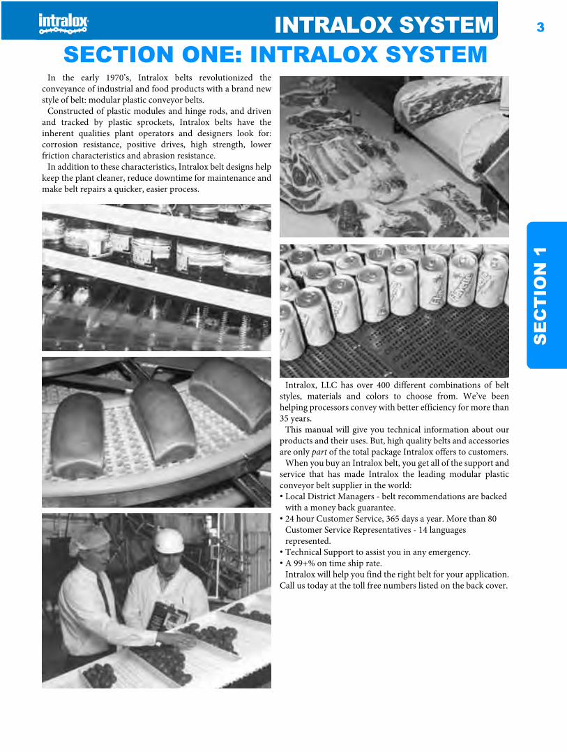
Intralox system SECTION ONE: INTRALOX SYSTEMIn the early 1970’s, Intralox belts revolutionized the
conveyance of industrial and food products with a brand newstyle of belt: modular plastic conveyor belts.
Constructed of plastic modules and hinge rods, and drivenand tracked by plastic sprockets, Intralox belts have theinherent qualities plant operators and designers look for:corrosion resistance, positive drives, high strength, lowerfriction characteristics and abrasion resistance.
In addition to these characteristics, Intralox belt designs helpkeep the plant cleaner, reduce downtime for maintenance andmake belt repairs a quicker, easier process.
Intralox, LLC has over 400 different combinations of beltstyles, materials and colors to choose from. We’ve beenhelping processors convey with better efficiency for more than35 years.
This manual will give you technical information about ourproducts and their uses. But, high quality belts and accessoriesare only part of the total package Intralox offers to customers.
When you buy an Intralox belt, you get all of the support andservice that has made Intralox the leading modular plasticconveyor belt supplier in the world:• Local District Managers - belt recommendations are backed
with a money back guarantee.• 24 hour Customer Service, 365 days a year. More than 80
Customer Service Representatives - 14 languages represented.
• Technical Support to assist you in any emergency.• A 99+% on time ship rate.
Intralox will help you find the right belt for your application.Call us today at the toll free numbers listed on the back cover.
4 INTRALOX SYSTEMS
EC
TIO
N 1
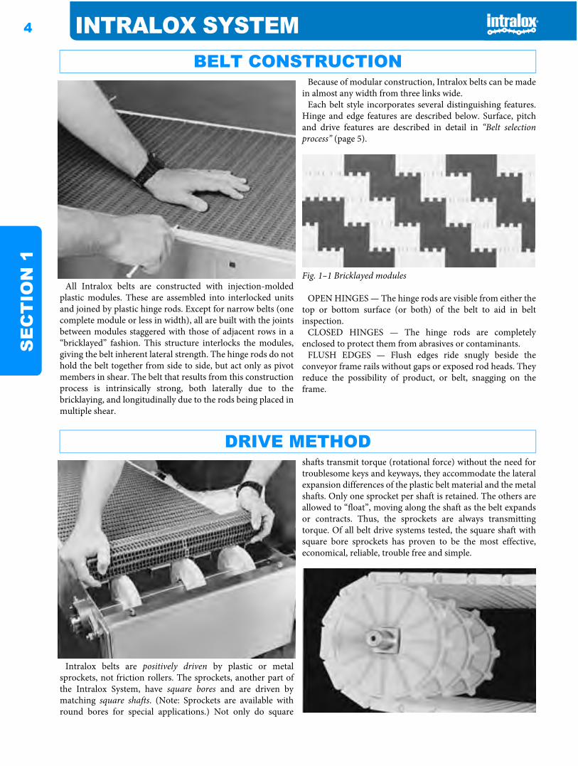
All Intralox belts are constructed with injection-moldedplastic modules. These are assembled into interlocked unitsand joined by plastic hinge rods. Except for narrow belts (onecomplete module or less in width), all are built with the jointsbetween modules staggered with those of adjacent rows in a“bricklayed” fashion. This structure interlocks the modules,giving the belt inherent lateral strength. The hinge rods do nothold the belt together from side to side, but act only as pivotmembers in shear. The belt that results from this constructionprocess is intrinsically strong, both laterally due to thebricklaying, and longitudinally due to the rods being placed inmultiple shear.
Because of modular construction, Intralox belts can be madein almost any width from three links wide.
Each belt style incorporates several distinguishing features.Hinge and edge features are described below. Surface, pitchand drive features are described in detail in “Belt selectionprocess” (page 5).
Fig. 1–1 Bricklayed modules
OPEN HINGES — The hinge rods are visible from either thetop or bottom surface (or both) of the belt to aid in beltinspection.
CLOSED HINGES — The hinge rods are completelyenclosed to protect them from abrasives or contaminants.
FLUSH EDGES — Flush edges ride snugly beside theconveyor frame rails without gaps or exposed rod heads. Theyreduce the possibility of product, or belt, snagging on theframe.
Intralox belts are positively driven by plastic or metalsprockets, not friction rollers. The sprockets, another part ofthe Intralox System, have square bores and are driven bymatching square shafts. (Note: Sprockets are available withround bores for special applications.) Not only do square
shafts transmit torque (rotational force) without the need fortroublesome keys and keyways, they accommodate the lateralexpansion differences of the plastic belt material and the metalshafts. Only one sprocket per shaft is retained. The others areallowed to “float”, moving along the shaft as the belt expandsor contracts. Thus, the sprockets are always transmittingtorque. Of all belt drive systems tested, the square shaft withsquare bore sprockets has proven to be the most effective,economical, reliable, trouble free and simple.
BELT CONSTRUCTION
DRIVE METHOD
INTRALOX SYSTEM 5
SE
CT
ION
1
Intralox conveyor belts are available in a variety of styles,materials and colors, with many accessory options. In order tomake the appropriate selections when designing for aparticular application, reliable information about operatingand environmental conditions is critical.
Factors to evaluate include:• The type of belt system: straight running or sideflexing• The overall dimensions of the installed belt: length between
driving and idling shafts, width, elevation changes• The speed of belt travel• The characteristics of the product to be conveyed:
1. density2. unit size and shape3. hardness, toughness, brittleness, rigidity4. texture (smooth, rough, granular, lumpy, spongy. . .)5. corrosiveness6. moisture content7. temperature8. frictional nature
• Any process change in the product during conveyance:1. heating
2. cooling3. washing, rinsing, draining4. drying
• The sanitary and cleanliness requirements and conditions:1. USDA-FSIS approval2. harsh temperatures or chemicals3. continuous on-line cleaning
• The planned methods of product loading and removal — smooth or impact transfers
• The characteristics of the operating environment:1. temperature2. moisture, humidity3. chemical nature (acid, base, etc.)4. abrasive materials (sand, grit, etc.)5. hazardous materials (dusts, vapors, etc.)
• The type of drive system:1. motors2. chains.
For more detailed information, see “Section three: Designguidelines” (page 317).
All Intralox belts can be used as straight running belts.Series 2200, Series 2400, Series 2600, Series 2700,Series 2800, Series 3000 and Series 4000 are designedfor sideflexing applications.
Intralox belts and accessories are available in standard andspecial application materials. For complete descriptions of thestandard and special application belt materials see, “Standardbelt materials” (page 18) and “Special application beltmaterials” (page 18).
Contact the Intralox Sales Engineering Department orCustomer Service for more information. Current telephonenumbers are listed on the back cover.
For specific recommendations on chemical properties, see“Chemical Resistance Guide” (page 355).
Next in the process of choosing the belt for your applicationis to determine the BELT SURFACE or STYLE best suitedfor the product or material being conveyed.
The PITCH of the belt is the next differentiating feature.Intralox belts are available in 0.50 in. (12.7 mm), 0.60 in.(15.2 mm), 1.00 in. (25.4 mm), 1.07 in. (27.2 mm), 1.25 in.(31.8 mm), 1.44 in. (36.6 mm), 1.50 in. (38.1 mm), 2.00 in.(50.8 mm), 2.07 in. (52.6 mm) and 2.50 in. (63.5 mm) pitches.Smaller pitch reduces chordal action (over similar sizesprockets) and the space required for product transfer.
DRIVE METHOD should also be considered. There are twodrive methods used by Intralox: hinge-driven and center-driven. Where back tension is an important consideration,drive method plays a significant role.
Note: Unless otherwise noted, the belts have fully flushedges.
DESIGN REQUIREMENTS
BELT SELECTION PROCESSSTEP ONE: Choose the right type of BELT SYSTEM— straight running or sideflexing.
STEP TWO: Choose the right MATERIAL for your application.
STEP THREE: Select the best belt surface, pitch and drive method.
6 INTRALOX SYSTEMS
EC
TIO
N 1
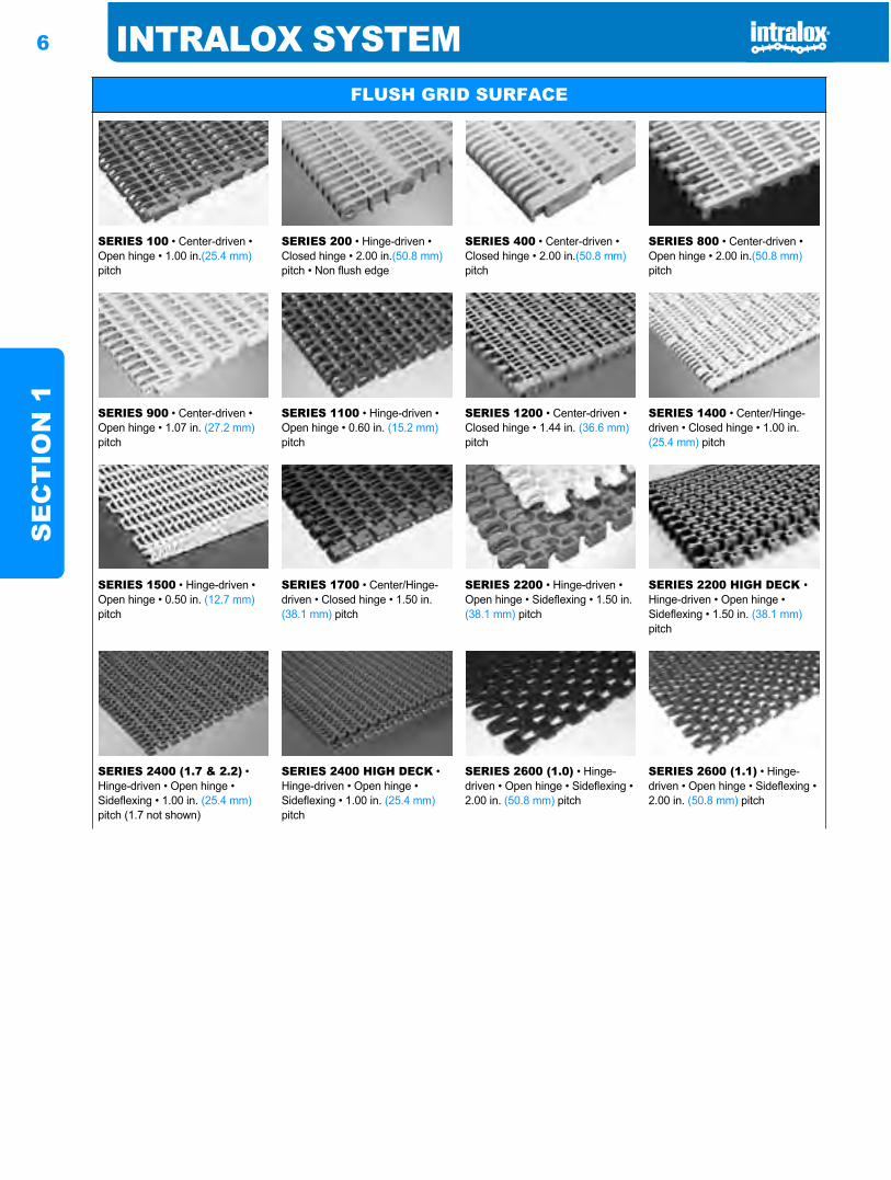
FLUSH GRID SURFACE
SERIES 100 • Center-driven • Open hinge • 1.00 in.(25.4 mm)pitch
SERIES 200 • Hinge-driven • Closed hinge • 2.00 in.(50.8 mm)pitch • Non flush edge
SERIES 400 • Center-driven • Closed hinge • 2.00 in.(50.8 mm)pitch
SERIES 800 • Center-driven • Open hinge • 2.00 in.(50.8 mm)pitch
SERIES 900 • Center-driven • Open hinge • 1.07 in. (27.2 mm)pitch
SERIES 1100 • Hinge-driven • Open hinge • 0.60 in. (15.2 mm)pitch
SERIES 1200 • Center-driven • Closed hinge • 1.44 in. (36.6 mm)pitch
SERIES 1400 • Center/Hinge-driven • Closed hinge • 1.00 in. (25.4 mm) pitch
SERIES 1500 • Hinge-driven • Open hinge • 0.50 in. (12.7 mm)pitch
SERIES 1700 • Center/Hinge-driven • Closed hinge • 1.50 in. (38.1 mm) pitch
SERIES 2200 • Hinge-driven • Open hinge • Sideflexing • 1.50 in. (38.1 mm) pitch
SERIES 2200 HIGH DECK •Hinge-driven • Open hinge • Sideflexing • 1.50 in. (38.1 mm)pitch
SERIES 2400 (1.7 & 2.2) • Hinge-driven • Open hinge • Sideflexing • 1.00 in. (25.4 mm)pitch (1.7 not shown)
SERIES 2400 HIGH DECK • Hinge-driven • Open hinge • Sideflexing • 1.00 in. (25.4 mm)pitch
SERIES 2600 (1.0) • Hinge-driven • Open hinge • Sideflexing • 2.00 in. (50.8 mm) pitch
SERIES 2600 (1.1) • Hinge-driven • Open hinge • Sideflexing • 2.00 in. (50.8 mm) pitch
INTRALOX SYSTEM 7
SE
CT
ION
1
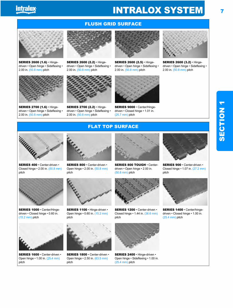
SERIES 2600 (1.6) • Hinge-driven • Open hinge • Sideflexing • 2.00 in. (50.8 mm) pitch
SERIES 2600 (2.2) • Hinge-driven • Open hinge • Sideflexing • 2.00 in. (50.8 mm) pitch
SERIES 2600 (2.5) • Hinge-driven • Open hinge • Sideflexing • 2.00 in. (50.8 mm) pitch
SERIES 2600 (3.2) • Hinge-driven • Open hinge • Sideflexing • 2.00 in. (50.8 mm) pitch
SERIES 2700 (1.6) • Hinge-driven • Open hinge • Sideflexing • 2.00 in. (50.8 mm) pitch
SERIES 2700 (2.2) • Hinge-driven • Open hinge • Sideflexing • 2.00 in. (50.8 mm) pitch
SERIES 9000 • Center/Hinge-driven • Closed hinge • 1.01 in. (25.7 mm) pitch
FLUSH GRID SURFACE
FLAT TOP SURFACE
SERIES 400 • Center-driven • Closed hinge • 2.00 in. (50.8 mm)pitch
SERIES 800 • Center-driven • Open hinge • 2.00 in. (50.8 mm)pitch
SERIES 800 TOUGH • Center-driven • Open hinge • 2.00 in. (50.8 mm) pitch
SERIES 900 • Center-driven • Closed hinge • 1.07 in. (27.2 mm)pitch
SERIES 1000 • Center/Hinge-driven • Closed hinge • 0.60 in. (15.2 mm) pitch
SERIES 1100 • Hinge-driven • Open hinge • 0.60 in. (15.2 mm)pitch
SERIES 1200 • Center-driven • Closed hinge • 1.44 in. (36.6 mm)pitch
SERIES 1400 • Center/hinge-driven • Closed hinge • 1.00 in. (25.4 mm) pitch
SERIES 1600 • Center-driven • Open hinge • 1.00 in. (25.4 mm)pitch
SERIES 1800 • Center-driven • Open hinge • 2.50 in. (63.5 mm)pitch
SERIES 2400 • Hinge-driven • Open hinge • Sideflexing • 1.00 in. (25.4 mm) pitch
8 INTRALOX SYSTEMS
EC
TIO
N 1
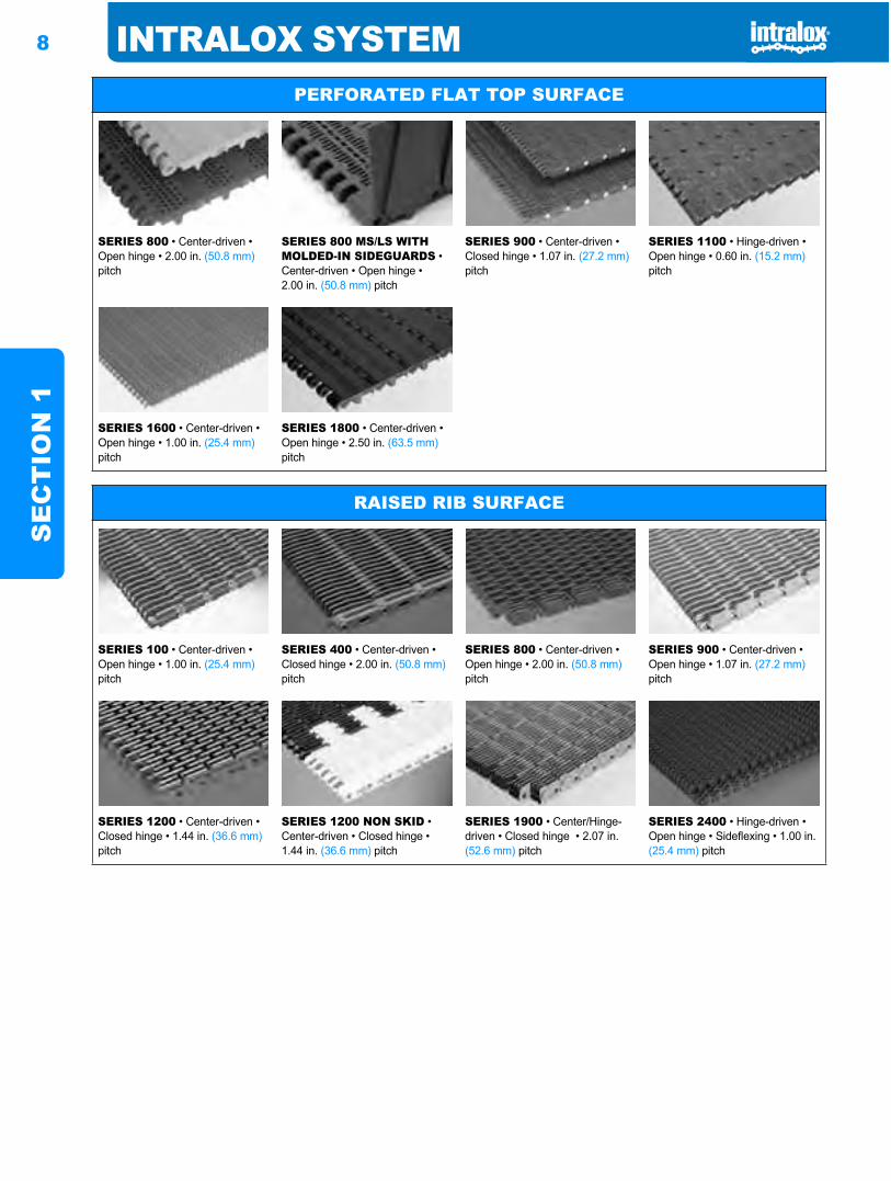
PERFORATED FLAT TOP SURFACE
SERIES 800 • Center-driven • Open hinge • 2.00 in. (50.8 mm)pitch
SERIES 800 MS/LS WITH MOLDED-IN SIDEGUARDS • Center-driven • Open hinge • 2.00 in. (50.8 mm) pitch
SERIES 900 • Center-driven • Closed hinge • 1.07 in. (27.2 mm)pitch
SERIES 1100 • Hinge-driven • Open hinge • 0.60 in. (15.2 mm)pitch
SERIES 1600 • Center-driven • Open hinge • 1.00 in. (25.4 mm)pitch
SERIES 1800 • Center-driven • Open hinge • 2.50 in. (63.5 mm)pitch
RAISED RIB SURFACE
SERIES 100 • Center-driven • Open hinge • 1.00 in. (25.4 mm)pitch
SERIES 400 • Center-driven • Closed hinge • 2.00 in. (50.8 mm)pitch
SERIES 800 • Center-driven • Open hinge • 2.00 in. (50.8 mm)pitch
SERIES 900 • Center-driven • Open hinge • 1.07 in. (27.2 mm)pitch
SERIES 1200 • Center-driven • Closed hinge • 1.44 in. (36.6 mm)pitch
SERIES 1200 NON SKID • Center-driven • Closed hinge • 1.44 in. (36.6 mm) pitch
SERIES 1900 • Center/Hinge-driven • Closed hinge • 2.07 in. (52.6 mm) pitch
SERIES 2400 • Hinge-driven • Open hinge • Sideflexing • 1.00 in. (25.4 mm) pitch
INTRALOX SYSTEM 9
SE
CT
ION
1
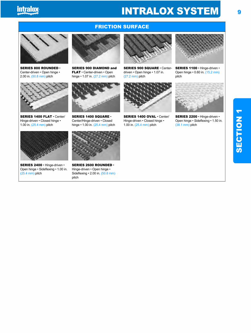
FRICTION SURFACE
SERIES 800 ROUNDED • Center-driven • Open hinge • 2.00 in. (50.8 mm) pitch
SERIES 900 DIAMOND and FLAT • Center-driven • Open hinge • 1.07 in. (27.2 mm) pitch
SERIES 900 SQUARE • Center-driven • Open hinge • 1.07 in. (27.2 mm) pitch
SERIES 1100 • Hinge-driven • Open hinge • 0.60 in. (15.2 mm)pitch
SERIES 1400 FLAT • Center/Hinge-driven • Closed hinge • 1.00 in. (25.4 mm) pitch
SERIES 1400 SQUARE • Center/Hinge-driven • Closed hinge • 1.00 in. (25.4 mm) pitch
SERIES 1400 OVAL • Center/Hinge-driven • Closed hinge • 1.00 in. (25.4 mm) pitch
SERIES 2200 • Hinge-driven • Open hinge • Sideflexing • 1.50 in. (38.1 mm) pitch
SERIES 2400 • Hinge-driven • Open hinge • Sideflexing • 1.00 in. (25.4 mm) pitch
SERIES 2600 ROUNDED • Hinge-driven • Open hinge • Sideflexing • 2.00 in. (50.8 mm)pitch
10 INTRALOX SYSTEMS
EC
TIO
N 1
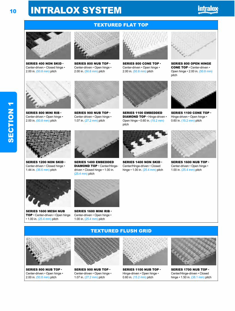
TEXTURED FLAT TOP
SERIES 400 NON SKID • Center-driven • Closed hinge • 2.00 in. (50.8 mm) pitch
SERIES 800 NUB TOP • Center-driven • Open hinge • 2.00 in. (50.8 mm) pitch
SERIES 800 CONE TOP • Center-driven • Open hinge • 2.00 in. (50.8 mm) pitch
SERIES 800 OPEN HINGE CONE TOP • Center-driven • Open hinge • 2.00 in. (50.8 mm)pitch
SERIES 800 MINI RIB • Center-driven • Open hinge • 2.00 in. (50.8 mm) pitch
SERIES 900 NUB TOP • Center-driven • Open hinge • 1.07 in. (27.2 mm) pitch
SERIES 1100 EMBEDDED DIAMOND TOP • Hinge-driven • Open hinge • 0.60 in. (15.2 mm)pitch
SERIES 1100 CONE TOP • Hinge-driven • Open hinge • 0.60 in. (15.2 mm) pitch
SERIES 1200 NON SKID • Center-driven • Closed hinge • 1.44 in. (36.6 mm) pitch
SERIES 1400 EMBEDDED DIAMOND TOP • Center/Hinge-driven • Closed hinge • 1.00 in. (25.4 mm) pitch
SERIES 1400 NON SKID • Center/Hinge-driven • Closed hinge • 1.00 in. (25.4 mm) pitch
SERIES 1600 NUB TOP • Center-driven • Open hinge • 1.00 in. (25.4 mm) pitch
SERIES 1600 MESH NUB TOP • Center-driven • Open hinge • 1.00 in. (25.4 mm) pitch
SERIES 1600 MINI RIB • Center-driven • Open hinge • 1.00 in. (25.4 mm) pitch
TEXTURED FLUSH GRID
SERIES 800 NUB TOP • Center-driven • Open hinge • 2.00 in. (50.8 mm) pitch
SERIES 900 NUB TOP • Center-driven • Open hinge • 1.07 in. (27.2 mm) pitch
SERIES 1100 NUB TOP • Hinge-driven • Open hinge • 0.60 in. (15.2 mm) pitch
SERIES 1700 NUB TOP • Center/Hinge-driven • Closed hinge • 1.50 in. (38.1 mm) pitch
INTRALOX SYSTEM 11
SE
CT
ION
1
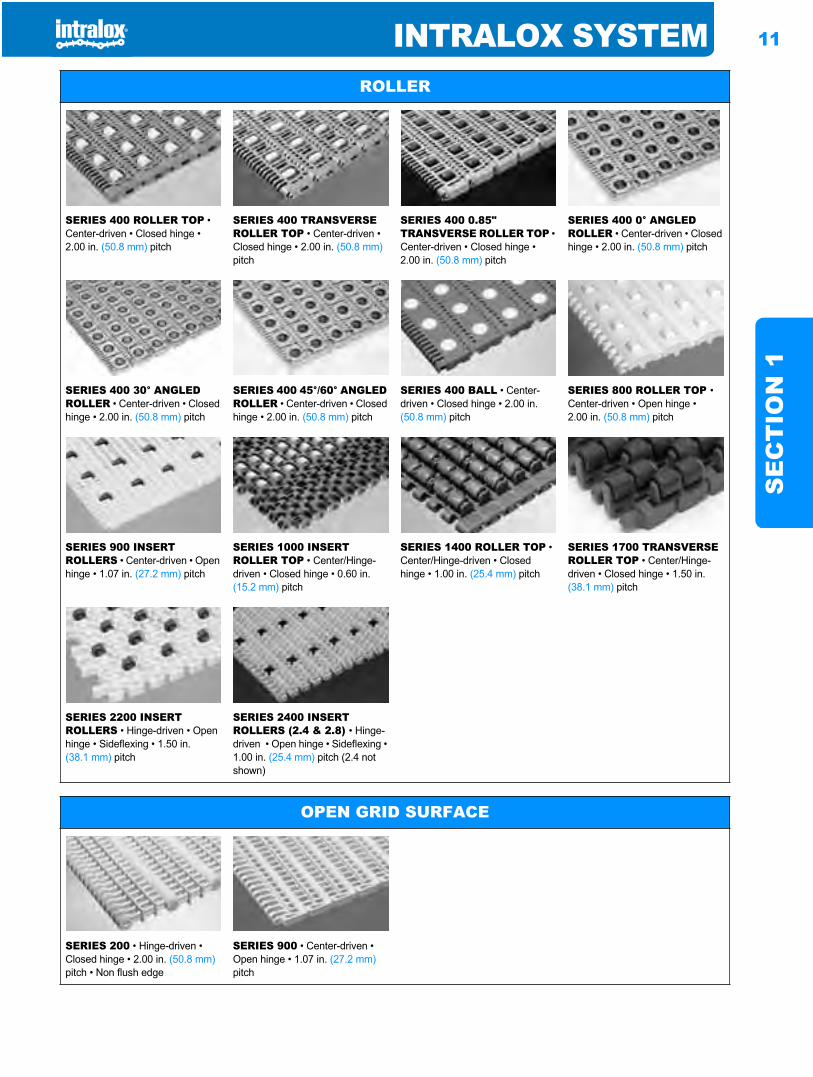
ROLLER
SERIES 400 ROLLER TOP • Center-driven • Closed hinge • 2.00 in. (50.8 mm) pitch
SERIES 400 TRANSVERSE ROLLER TOP • Center-driven • Closed hinge • 2.00 in. (50.8 mm)pitch
SERIES 400 0.85" TRANSVERSE ROLLER TOP • Center-driven • Closed hinge • 2.00 in. (50.8 mm) pitch
SERIES 400 0° ANGLED ROLLER • Center-driven • Closed hinge • 2.00 in. (50.8 mm) pitch
SERIES 400 30° ANGLED ROLLER • Center-driven • Closed hinge • 2.00 in. (50.8 mm) pitch
SERIES 400 45°/60° ANGLED ROLLER • Center-driven • Closed hinge • 2.00 in. (50.8 mm) pitch
SERIES 400 BALL • Center-driven • Closed hinge • 2.00 in. (50.8 mm) pitch
SERIES 800 ROLLER TOP •Center-driven • Open hinge • 2.00 in. (50.8 mm) pitch
SERIES 900 INSERT ROLLERS • Center-driven • Open hinge • 1.07 in. (27.2 mm) pitch
SERIES 1000 INSERT ROLLER TOP • Center/Hinge-driven • Closed hinge • 0.60 in. (15.2 mm) pitch
SERIES 1400 ROLLER TOP • Center/Hinge-driven • Closed hinge • 1.00 in. (25.4 mm) pitch
SERIES 1700 TRANSVERSE ROLLER TOP • Center/Hinge-driven • Closed hinge • 1.50 in. (38.1 mm) pitch
SERIES 2200 INSERT ROLLERS • Hinge-driven • Open hinge • Sideflexing • 1.50 in. (38.1 mm) pitch
SERIES 2400 INSERT ROLLERS (2.4 & 2.8) • Hinge-driven • Open hinge • Sideflexing • 1.00 in. (25.4 mm) pitch (2.4 not shown)
OPEN GRID SURFACE
SERIES 200 • Hinge-driven • Closed hinge • 2.00 in. (50.8 mm)pitch • Non flush edge
SERIES 900 • Center-driven • Open hinge • 1.07 in. (27.2 mm)pitch
12 INTRALOX SYSTEMS
EC
TIO
N 1
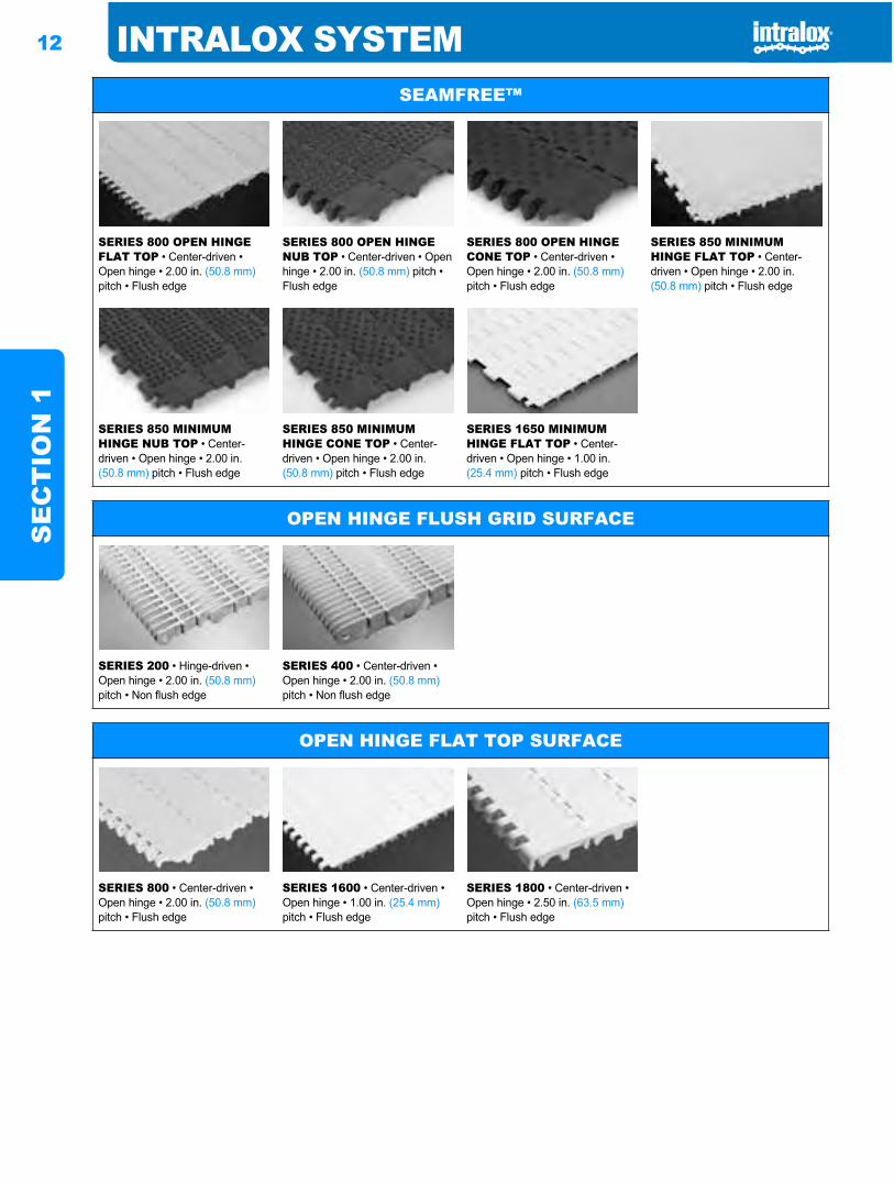
SEAMFREE™
SERIES 800 OPEN HINGE FLAT TOP • Center-driven • Open hinge • 2.00 in. (50.8 mm)pitch • Flush edge
SERIES 800 OPEN HINGE NUB TOP • Center-driven • Open hinge • 2.00 in. (50.8 mm) pitch • Flush edge
SERIES 800 OPEN HINGE CONE TOP • Center-driven • Open hinge • 2.00 in. (50.8 mm)pitch • Flush edge
SERIES 850 MINIMUM HINGE FLAT TOP • Center-driven • Open hinge • 2.00 in. (50.8 mm) pitch • Flush edge
SERIES 850 MINIMUM HINGE NUB TOP • Center-driven • Open hinge • 2.00 in. (50.8 mm) pitch • Flush edge
SERIES 850 MINIMUM HINGE CONE TOP • Center-driven • Open hinge • 2.00 in. (50.8 mm) pitch • Flush edge
SERIES 1650 MINIMUM HINGE FLAT TOP • Center-driven • Open hinge • 1.00 in. (25.4 mm) pitch • Flush edge
OPEN HINGE FLUSH GRID SURFACE
SERIES 200 • Hinge-driven • Open hinge • 2.00 in. (50.8 mm)pitch • Non flush edge
SERIES 400 • Center-driven • Open hinge • 2.00 in. (50.8 mm)pitch • Non flush edge
OPEN HINGE FLAT TOP SURFACE
SERIES 800 • Center-driven • Open hinge • 2.00 in. (50.8 mm)pitch • Flush edge
SERIES 1600 • Center-driven • Open hinge • 1.00 in. (25.4 mm)pitch • Flush edge
SERIES 1800 • Center-driven • Open hinge • 2.50 in. (63.5 mm)pitch • Flush edge
INTRALOX SYSTEM 13
SE
CT
ION
1
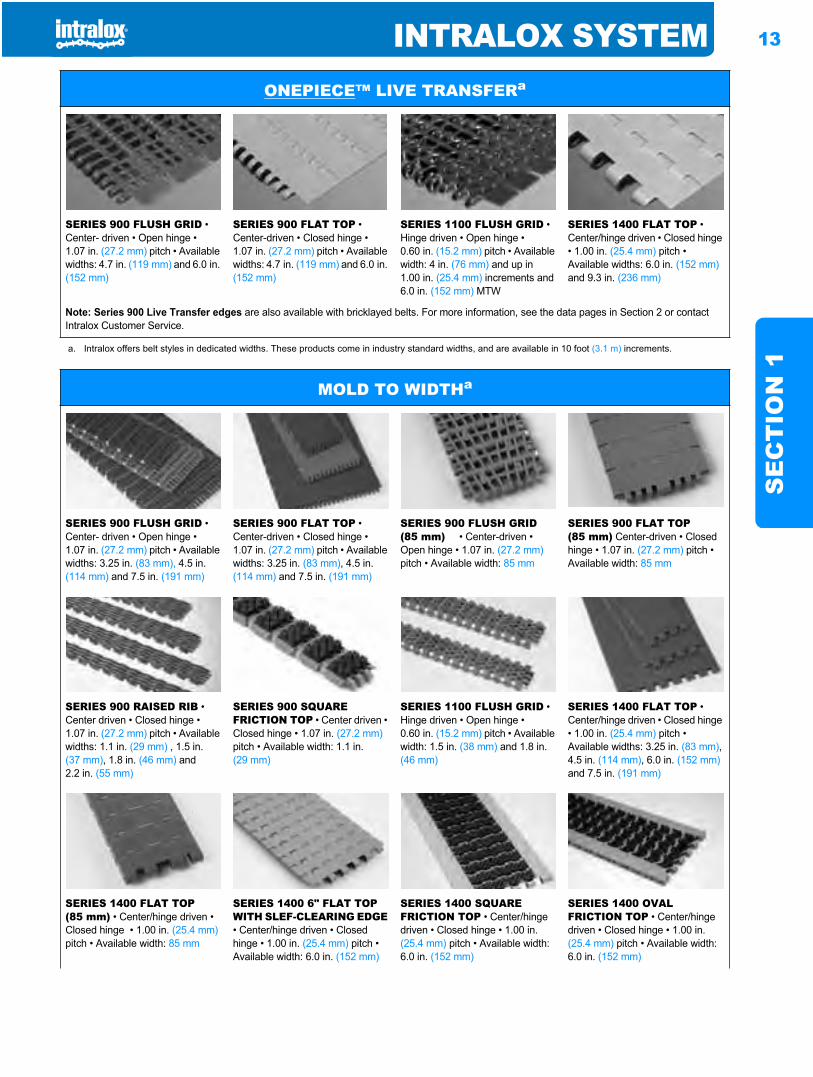
ONEPIECE™ LIVE TRANSFERa
SERIES 900 FLUSH GRID • Center- driven • Open hinge • 1.07 in. (27.2 mm) pitch • Available widths: 4.7 in. (119 mm) and 6.0 in. (152 mm)
SERIES 900 FLAT TOP • Center-driven • Closed hinge • 1.07 in. (27.2 mm) pitch • Available widths: 4.7 in. (119 mm) and 6.0 in. (152 mm)
SERIES 1100 FLUSH GRID • Hinge driven • Open hinge • 0.60 in. (15.2 mm) pitch • Available width: 4 in. (76 mm) and up in 1.00 in. (25.4 mm) increments and 6.0 in. (152 mm) MTW
SERIES 1400 FLAT TOP • Center/hinge driven • Closed hinge • 1.00 in. (25.4 mm) pitch • Available widths: 6.0 in. (152 mm)and 9.3 in. (236 mm)
Note: Series 900 Live Transfer edges are also available with bricklayed belts. For more information, see the data pages in Section 2 or contact Intralox Customer Service.
a. Intralox offers belt styles in dedicated widths. These products come in industry standard widths, and are available in 10 foot (3.1 m) increments.
MOLD TO WIDTHa
SERIES 900 FLUSH GRID • Center- driven • Open hinge • 1.07 in. (27.2 mm) pitch • Available widths: 3.25 in. (83 mm), 4.5 in. (114 mm) and 7.5 in. (191 mm)
SERIES 900 FLAT TOP • Center-driven • Closed hinge • 1.07 in. (27.2 mm) pitch • Available widths: 3.25 in. (83 mm), 4.5 in. (114 mm) and 7.5 in. (191 mm)
SERIES 900 FLUSH GRID (85 mm) • Center-driven • Open hinge • 1.07 in. (27.2 mm)pitch • Available width: 85 mm
SERIES 900 FLAT TOP (85 mm) Center-driven • Closed hinge • 1.07 in. (27.2 mm) pitch • Available width: 85 mm
SERIES 900 RAISED RIB • Center driven • Closed hinge • 1.07 in. (27.2 mm) pitch • Available widths: 1.1 in. (29 mm) , 1.5 in. (37 mm), 1.8 in. (46 mm) and 2.2 in. (55 mm)
SERIES 900 SQUARE FRICTION TOP • Center driven • Closed hinge • 1.07 in. (27.2 mm)pitch • Available width: 1.1 in. (29 mm)
SERIES 1100 FLUSH GRID • Hinge driven • Open hinge • 0.60 in. (15.2 mm) pitch • Available width: 1.5 in. (38 mm) and 1.8 in. (46 mm)
SERIES 1400 FLAT TOP • Center/hinge driven • Closed hinge • 1.00 in. (25.4 mm) pitch • Available widths: 3.25 in. (83 mm),4.5 in. (114 mm), 6.0 in. (152 mm)and 7.5 in. (191 mm)
SERIES 1400 FLAT TOP (85 mm) • Center/hinge driven • Closed hinge • 1.00 in. (25.4 mm)pitch • Available width: 85 mm
SERIES 1400 6" FLAT TOP WITH SLEF-CLEARING EDGE• Center/hinge driven • Closed hinge • 1.00 in. (25.4 mm) pitch • Available width: 6.0 in. (152 mm)
SERIES 1400 SQUARE FRICTION TOP • Center/hinge driven • Closed hinge • 1.00 in. (25.4 mm) pitch • Available width: 6.0 in. (152 mm)
SERIES 1400 OVAL FRICTION TOP • Center/hinge driven • Closed hinge • 1.00 in. (25.4 mm) pitch • Available width: 6.0 in. (152 mm)
14 INTRALOX SYSTEMS
EC
TIO
N 1
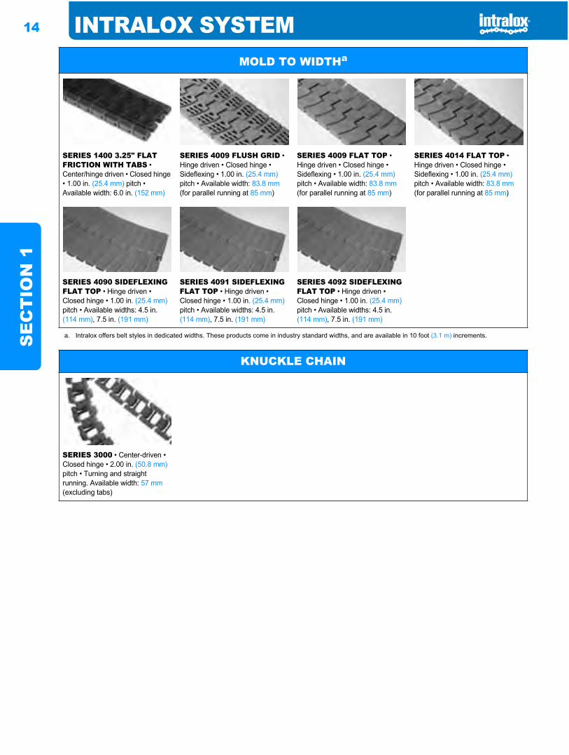
SERIES 1400 3.25" FLAT FRICTION WITH TABS • Center/hinge driven • Closed hinge • 1.00 in. (25.4 mm) pitch • Available width: 6.0 in. (152 mm)
SERIES 4009 FLUSH GRID • Hinge driven • Closed hinge • Sideflexing • 1.00 in. (25.4 mm)pitch • Available width: 83.8 mm(for parallel running at 85 mm)
SERIES 4009 FLAT TOP • Hinge driven • Closed hinge • Sideflexing • 1.00 in. (25.4 mm)pitch • Available width: 83.8 mm(for parallel running at 85 mm)
SERIES 4014 FLAT TOP • Hinge driven • Closed hinge • Sideflexing • 1.00 in. (25.4 mm)pitch • Available width: 83.8 mm(for parallel running at 85 mm)
SERIES 4090 SIDEFLEXING FLAT TOP • Hinge driven • Closed hinge • 1.00 in. (25.4 mm)pitch • Available widths: 4.5 in. (114 mm), 7.5 in. (191 mm)
SERIES 4091 SIDEFLEXING FLAT TOP • Hinge driven • Closed hinge • 1.00 in. (25.4 mm)pitch • Available widths: 4.5 in. (114 mm), 7.5 in. (191 mm)
SERIES 4092 SIDEFLEXING FLAT TOP • Hinge driven • Closed hinge • 1.00 in. (25.4 mm)pitch • Available widths: 4.5 in. (114 mm), 7.5 in. (191 mm)
a. Intralox offers belt styles in dedicated widths. These products come in industry standard widths, and are available in 10 foot (3.1 m) increments.
MOLD TO WIDTHa
KNUCKLE CHAIN
SERIES 3000 • Center-driven • Closed hinge • 2.00 in. (50.8 mm)pitch • Turning and straight running. Available width: 57 mm(excluding tabs)
INTRALOX SYSTEM 15
SE
CT
ION
1
After choosing the material and surface style to meet yourneeds, next determine if the belt selected is strong enough tomeet your application requirements.
Analysis for straight running belts:After making a tentative selection from the Series and Styles
listed above, turn to the “Belt Selection Instructions” (page 36),Product Line, for instructions to determine the Belt Pulland Adjusted Belt Pull for comparison with the AllowableStrength for that belt. In order to make the necessarycalculations for Belt Pull, gather this information:1. the product weight applied to the belt, in pounds per square
foot (or kilograms per square meter),2. the length of the proposed conveyor, in feet (or meters),3. any elevation changes in the conveyor, in feet (or meters),4. the desired operating speed, in feet per minute (or meters
per minute),5. the percent of belt area “backed-up” with stationary
product,6. the maximum operating temperature to be experienced by
the belt, in degrees Fahrenheit (or degrees Celsius),7. the type of material upon which the belt will run in the
conveyor frame, e.g., Stainless or Carbon Steel, Ultra High Molecular Weight Polyethylene (UHMW), High Density Polyethylene (HDPE), nylon, etc., and
8. the Service Duty, i.e., frequent start-ups under heavy load, an elevating or “pushing conveyor”, etc.
Analysis for sideflexing belts:These belts require a more complex analysis. The following
additional information is required:9. the length of each straight run,10.the turning angle and direction of each turn, and11.the inside turning radius, measured from the inside edge of
the belt.
The following factors should be considered beforeproceeding any further with belt selection.
BELT SPEEDThe belt speed affects the wear and life expectancy in these
ways:1. Hinge and sprocket wear: The frequency of module
rotation about the hinge rods (as the belt engages and disengages the sprockets) is directly proportional to speed. The rotary motion can cause wear to both rods and modules. This wear rate, however, is inversely proportional to the belt’s length, i.e., a shorter conveyor should wear faster than a longer one if both are running at the same speed. It follows that sprocket/tooth wear is directly proportional to speed. Sprockets with more teeth cause less module/hinge rotation, consequently less wear than sprockets with fewer teeth.
2. Belt surface wear: As belts slide over carryways, returnways, shoes and other fixed members, some wear is to be expected. The most destructive conditions are high speed, heavy loads, abrasive materials, and dry or non lubricated operation.
3. Dynamic effects of high speed operation: Two effects of high speed conditions are belt “whipping” or oscillating in unsupported sections and “load surges” as heavy, stationary products are suddenly accelerated to belt speed. Where possible, both conditions should be avoided.
ABRASIVE CONDITIONS AND FRICTION EFFECTSAbrasives in a conveying application must be identified, the
best combination of materials chosen and protective featuresincluded in order to extend belt life. Abrasives will wear awayany material, but the correct material choice can significantlyincrease belt life. In highly abrasive applications, the hingerods and sprockets are usually the first elements to be affected.Hinge rod wear typically results in excessive belt-pitchelongation. This may prevent proper tooth engagement,increasing the wear on sprocket teeth. Intralox offers StainlessSteel split sprockets and Abrasion Resistant rods that work toincrease belt life.
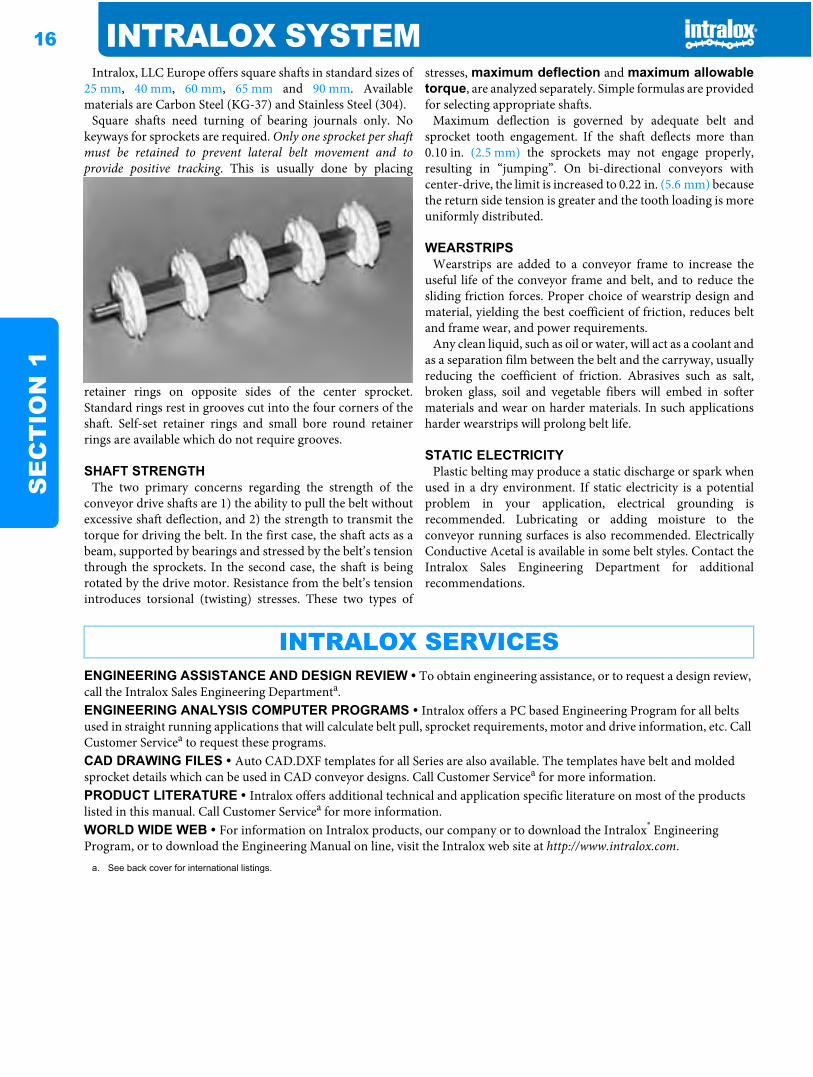
CHORDAL ACTION AND SPROCKET SELECTIONAs the modules of belts engage their driving sprockets, a
pulsation in the belt’s linear velocity occurs. This is due tochordal action, which is the rise and fall of a module as itrotates around a shaft’s center line. It is characteristic of allsprocket-driven belts and chains. The variation in speed isinversely proportional to the number of teeth on the sprocket.For example, a belt driven by a six tooth sprocket has apulsating speed variation of 13.4%, while a belt driven by a 19tooth sprocket has a variation of only 1.36%. In thoseapplications, where product tipping is a concern, or wheresmooth, even speed is critical, it is recommended thatsprockets with the maximum number of teeth available beselected.
SHAFTSIntralox, LLC USA can supply square shafts, machined to
your specification, in standard sizes of 5/8 in., 1 in., 1.5 in.,2.5 in., 3.5 in., 40 mm and 60 mm. Available materials areCarbon Steel (C-1018) (not available in 40mm and 60mm),Stainless Steel (303, 304 and 316) and Aluminium (6061-T6).Call Customer Service for availability and lead-times.
STEP FOUR: Select a belt of sufficient STRENGTH for your application.
STEP FIVE: Other important considerations.PULSATING SPEED VARIATION
SPEE
D V
AR
IATI
ON
, %
NUMBER OF TEETH ON SPROCKET
16 INTRALOX SYSTEMS
EC
TIO
N 1
Intralox, LLC Europe offers square shafts in standard sizes of25 mm, 40 mm, 60 mm, 65 mm and 90 mm. Availablematerials are Carbon Steel (KG-37) and Stainless Steel (304).
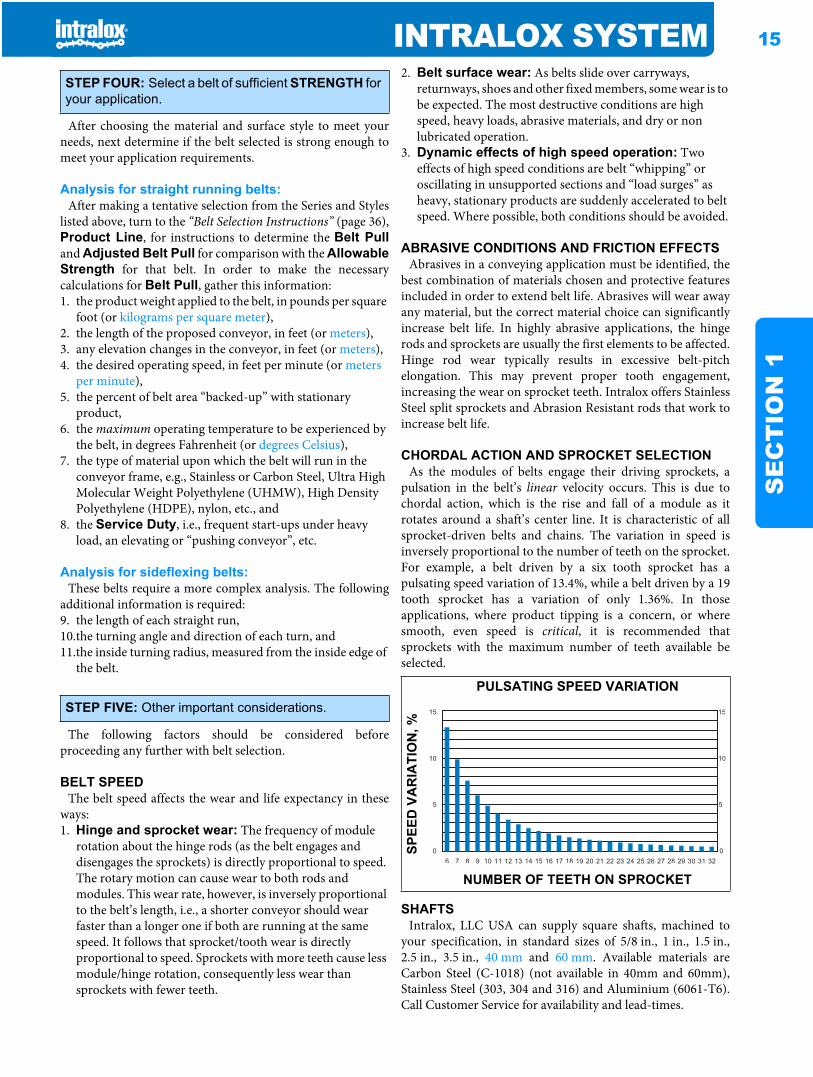
Square shafts need turning of bearing journals only. Nokeyways for sprockets are required. Only one sprocket per shaftmust be retained to prevent lateral belt movement and toprovide positive tracking. This is usually done by placing
retainer rings on opposite sides of the center sprocket.Standard rings rest in grooves cut into the four corners of theshaft. Self-set retainer rings and small bore round retainerrings are available which do not require grooves.
SHAFT STRENGTHThe two primary concerns regarding the strength of the
conveyor drive shafts are 1) the ability to pull the belt withoutexcessive shaft deflection, and 2) the strength to transmit thetorque for driving the belt. In the first case, the shaft acts as abeam, supported by bearings and stressed by the belt’s tensionthrough the sprockets. In the second case, the shaft is beingrotated by the drive motor. Resistance from the belt’s tensionintroduces torsional (twisting) stresses. These two types of
stresses, maximum deflection and maximum allowabletorque, are analyzed separately. Simple formulas are providedfor selecting appropriate shafts.
Maximum deflection is governed by adequate belt andsprocket tooth engagement. If the shaft deflects more than0.10 in. (2.5 mm) the sprockets may not engage properly,resulting in “jumping”. On bi-directional conveyors withcenter-drive, the limit is increased to 0.22 in. (5.6 mm) becausethe return side tension is greater and the tooth loading is moreuniformly distributed.
WEARSTRIPSWearstrips are added to a conveyor frame to increase the
useful life of the conveyor frame and belt, and to reduce thesliding friction forces. Proper choice of wearstrip design andmaterial, yielding the best coefficient of friction, reduces beltand frame wear, and power requirements.
Any clean liquid, such as oil or water, will act as a coolant andas a separation film between the belt and the carryway, usuallyreducing the coefficient of friction. Abrasives such as salt,broken glass, soil and vegetable fibers will embed in softermaterials and wear on harder materials. In such applicationsharder wearstrips will prolong belt life.
STATIC ELECTRICITYPlastic belting may produce a static discharge or spark when
used in a dry environment. If static electricity is a potentialproblem in your application, electrical grounding isrecommended. Lubricating or adding moisture to theconveyor running surfaces is also recommended. ElectricallyConductive Acetal is available in some belt styles. Contact theIntralox Sales Engineering Department for additionalrecommendations.
INTRALOX SERVICESENGINEERING ASSISTANCE AND DESIGN REVIEW • To obtain engineering assistance, or to request a design review, call the Intralox Sales Engineering Departmenta.ENGINEERING ANALYSIS COMPUTER PROGRAMS • Intralox offers a PC based Engineering Program for all belts used in straight running applications that will calculate belt pull, sprocket requirements, motor and drive information, etc. Call Customer Servicea to request these programs.CAD DRAWING FILES • Auto CAD.DXF templates for all Series are also available. The templates have belt and molded sprocket details which can be used in CAD conveyor designs. Call Customer Servicea for more information.PRODUCT LITERATURE • Intralox offers additional technical and application specific literature on most of the products listed in this manual. Call Customer Servicea for more information.WORLD WIDE WEB • For information on Intralox products, our company or to download the Intralox® Engineering Program, or to download the Engineering Manual on line, visit the Intralox web site at http://www.intralox.com.
a. See back cover for international listings.
PRODUCT LINE 17
SE
CT
ION
2
Product line SECTION TWO: PRODUCT LINE
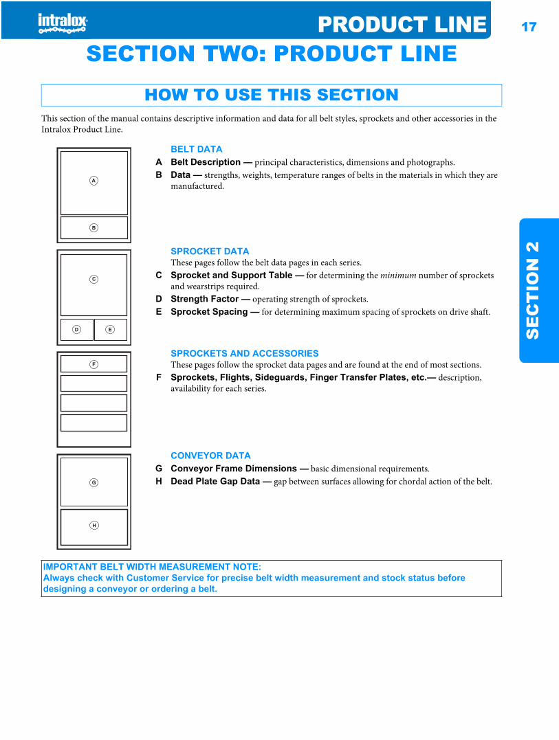
HOW TO USE THIS SECTIONThis section of the manual contains descriptive information and data for all belt styles, sprockets and other accessories in the Intralox Product Line.
BELT DATAA Belt Description — principal characteristics, dimensions and photographs.B Data — strengths, weights, temperature ranges of belts in the materials in which they are
manufactured.
SPROCKET DATAThese pages follow the belt data pages in each series.
C Sprocket and Support Table — for determining the minimum number of sprockets and wearstrips required.
D Strength Factor — operating strength of sprockets.E Sprocket Spacing — for determining maximum spacing of sprockets on drive shaft.
SPROCKETS AND ACCESSORIESThese pages follow the sprocket data pages and are found at the end of most sections.
F Sprockets, Flights, Sideguards, Finger Transfer Plates, etc.— description, availability for each series.
CONVEYOR DATAG Conveyor Frame Dimensions — basic dimensional requirements.H Dead Plate Gap Data — gap between surfaces allowing for chordal action of the belt.
B
A
ED
C
F
H
G
IMPORTANT BELT WIDTH MEASUREMENT NOTE:Always check with Customer Service for precise belt width measurement and stock status before designing a conveyor or ordering a belt.
18 PRODUCT LINES
EC
TIO
N 2
ACETAL thermoplastics are considerably stronger thanpolypropylene and polyethylene, and have a good balance ofmechanical and thermal properties.• Good fatigue endurance and resilience.• Low coefficient of friction, making it a good choice for
container handling and transport.• Temperature range is -50 °F (-46 °C) to 200 °F (93 °C).• Specific gravity is 1.40 and relatively impact resistant.• Acetal belts are fairly hard, so they are relatively cut and
scratch resistant.• This material complies with FDA regulations for use in food
processing and packaging applications, and is USDA-FSIS accepted (meat and poultry).
• USDA Dairy accepted, white acetal is available in some belt styles.
• A specially formulated UV resistant black acetal is available for applications that require UV protection. The UV resistant black acetal is not FDA approved, and is currently available in Series 1800 Mesh Top.
• Anti Static Acetal (AS Acetal) is available for applications where a slow static buildup has to be dissipated. With AS acetal, this dissipation is slow and improves in a humid environment. Anti Static Acetal is currently available in Series 400 Non Skid.
• This material complies with the requirements of EC Directive 2002/72/EC and all amendments to date for food contact.
POLYETHYLENE, another lightweight thermoplastic, ischaracterized by superior flexibility and high impact strength. • Buoyant in water, with a specific gravity of 0.95.• Excellent product release characteristics.• Exhibits excellent performance at much lower temperatures.• Temperature range is -100 °F (-73 °C) to 150 °F (66 °C).
(Check belt specifications for exact figures).• Resistant to many acids, bases and hydrocarbons.• Black polyethylene is recommended for low temperature
applications exposed to direct sunlight.
• This material complies with FDA regulations for use in food processing and packaging applications, and is USDA-FSIS accepted (meat and poultry).
• USDA Dairy accepted, natural polyethylene is available in some belt styles.
• This material complies with the requirements of EC Directive 2002/72/EC and all amendments to date for food contact.
POLYPROPYLENE is a standard material for use in generalapplications and where chemical resistance may be required.• Good balance between moderate strength and lightweight.• Buoyant in water, with a specific gravity of 0.90.• Temperature range is 34 °F (1 °C) to 220 °F (104 °C).• A relatively strong material in normal use, polypropylene
exhibits a somewhat brittle quality at low temperatures. It is not recommended in high impact conditions below 45 °F (7 °C).
• Good chemical resistance to many acids, bases, salts and alcohols.
• This material complies with FDA regulations for use in food processing and packaging applications, and is USDA-FSIS accepted (meat and poultry).
• USDA Dairy accepted, white polypropylene is available in some belt styles.
• This material complies with the requirements of EC Directive 2002/72/EC and all amendments to date for food contact.
• Black polypropylene is recommended for applications exposed to direct sunlight, and a specially formulated UV resistant black polypropylene is also available for applications that require even more UV protection. The UV resistant black PP is not FDA approved, and is currently available in Series 1800 Mesh Top, Series 1100 Flush Grid, Series 900 Flush Grid and Series 900 Perforated Flat Top.
ABRASION RESISTANT NYLON (AR), is available onlyfor Series 1700.• For abrasive (wet and dry), heavy-duty applications.• Available in Black and White which are both FDA approved.• Temperature range is -50 °F to 240 °F (-46 °C to 116 °C).• 0.5% expansion in belt width at 100% relative humidity.• Specific gravity of 1.06• Heat stabilized for superior outdoor wear.• Uses the same temperature factor table as regular Nylon.
DETECTABLE POLYPROPYLENE is available in theSeries 800 Flat Top and Series 1500 Flush Grid. Thismaterial was developed for applications in the food processingindustry where product contamination is a concern. It is
designed to be detectable by metal detectors or x-ray machinesand used upline from metal or x-ray detectors. It is speciallyformulated to enhance impact resistance.• Temperature range is 0 °F (-18 °C) to 150 °F (66 °C)• Metal filled material will not rust or expose hazardous sharp
fibers.• Buoyant in water, with a specific gravity of 0.96• Material has good impact resistance for temperatures above
34 °F (1 °C)• Testing the material on a metal detector in a production
environment is the best method for determining detection sensitivity.
• The thermal expansion coefficient is 0.0011 in/ft/ °F (0.17 mm/m/ °C)
STANDARD BELT MATERIALS
SPECIAL APPLICATION BELT MATERIALS
PRODUCT LINE 19
SE
CT
ION
2
• This material complies with the FDA regulations for use in food processing and packaging applications, and is USDA-FSIS (meat and poultry).
• The detectable material has Surface Resistivity per ASTM D257 of 545 Ohms per square.
• Material is NOT for use in metal detectors.• This material complies with the requirements of EC
Directive 2002/72/EC and all amendments to date for food contact.
EC (Electrically Conductive) ACETAL can be used tohelp dissipate static charges that might build up, especiallywhen moving cans or other conductive objects. A metal railingor carryway can be used to ground the belt, dissipating anycharge built up in the product. EC Acetal is usually spliced into“normal” belt sections (three rows of EC Acetal for every 2 ft.(0.61 m) of belt for Series 100 and Series 900, five rows forevery 2 ft. (0.61 m) of belt for Series 1100), though entirebelts can be made from EC Acetal.• The chemical resistance and friction factors match those of
regular acetal.• EC Acetal has a resistance of 60,000 Ohms per square,
compared to a resistance of several million Ohms per square in regular plastics.
• Its specific gravity is 1.40.• This material is not FDA compliant or USDA-FSIS accepted.• EC Acetal is only available in Series 100 Flush Grid,
Series 400 Flush Grid and Flat Top, Series 900 Flush Grid, Flat Top and Raised Rib, Series 1100 Flush Grid, and Series 1400 Flat Top belt styles.
ENDURALOX™ POLYPROPYLENE is a speciallyformulated material designed to maximize the life of Intraloxbelting in a pasteurizer environment by protecting themolecular structure of the polypropylene from environmentalfactors such as temperature cycling, bromine, and chlorine.• Same physical properties as standard polypropylene.• This material complies with FDA regulations for use in food
processing and packaging applications.
FLAME RETARDANT THERMOPLASTIC POLYESTER (FR-TPES) material is V-0 rated (UL94 @ 1/32"), and will not sustain a flame. Though the material will notactively burn, it will blacken and melt in the presence of flame.FR-TPES is stronger than polypropylene, but not as strong asacetal.• V-0 rated (UL94 @ 1/32").• FR-TPES’ temperature range is 40 °F (4 °C) to 150 °F (66 °C).• FR-TPES has a specific gravity of 1.45.• This material is not FDA compliant or USDA-FSIS accepted.• FR-TPES is available in Series 1100 Flush Grid, Series
900 Flush Grid, Series 900 Flush Grid ONEPIECE™ Live Transfer and Series 900 Perforated Flat Top.
HEAT RESISTANT NYLON (HR), is available in twogrades: FDA compliant, and non FDA compliant. The FDAHR Nylon complies with FDA regulations for use in foodprocessing and packaging applications.• UL94 flammability rating of V-2.
• FDA HR Nylon has an upper, continuous temperature limit of 240 °F (116 °C). For intermittent exposure, FDA HR Nylon has a rating limit of 270 °F (132 °C).
• Non FDA HR Nylon has an upper, continuous temperature limit of 310 °F (154 °C). For intermittent exposure, non FDA HR Nylon is rated at 360 °F (182 °C).
• The specific gravity of both grades is 1.13.• This product may not be used for food contact articles that
will come in contact with food containing alcohol.• These materials will absorb water in wet environments,
causing the belt to expand. The belt will also expand due to the temperature change. The thermal expansion coefficient is 0.00054 in/ft/°F (0.081 mm/m/°C).
• Both FDA HR Nylon and non FDA HR Nylon are available in Series 900 Flush Grid, Raised Rib, Flat Top and Perforated Flat Top styles for dry, elevated temperature applications. Series 1100 Flush Grid is available with non FDA HR nylon.
HIGH SPEED INTRALON™ is available for Series 2200and Series 2400 radius belts. This material was developedfor radius applications where the belt speed is over 150 feet perminute. The material has a high PV value that minimizes wearon the inside edge of radius belts.• High Speed Intralon™ Material is FDA compliant in Bone
White• High Speed Intralon™ Material is not recommended to be
used on the outside edge of turns for radius belts.• Maximum Belt Speed for radius conveyor: 600 fpm (straight
running direction)• This material will absorb water in wet environments, causing
the belt to expand.• Thermal Expansion: 0.00054 in/ft/F°• Specific Gravity: 1.13• Temperature information: -50°F to 180°F (-46 °C to 82 °C)
HIGH STRENGTH EC ACETAL (HSEC), is available forapplications that require static dissipation. HSEC material isstronger and less brittle than EC Acetal.• The chemical resistance and friction factors match those of
regular Acetal.• HSEC Acetal has a resistance of 60,000 Ohms per square.• The specific gravity of HSEC is 1.40.• This material is not FDA compliant or USDA-FSIS accepted.• This material is less brittle than EC Acetal.• This material is only available in Series 400 Non Skid,
and Series 1400 Non-Skid.
NYLON is available for applications requiring good dryabrasion and chemical resistance. The two limitations toNylon are that it absorbs water and is more susceptible to cutsand gouges than acetal. Because of material expansion causedby water absorption, Nylon is not recommended for very wetapplications. For example, at 100% relative humidity, theexpansion will be close to 3% (at equilibrium), making a 24 in.(610 mm) wide belt expand to 24.75 in. (629 mm).• Abrasion resistant in dry applications.• Good chemical resistance and low temperature performance.• Stronger than polypropylene.• Temperature range is -50 °F (-46 °C) to 180 °F (82 °C).
20 PRODUCT LINES
EC
TIO
N 2
• Good fatigue resistance.• Specific gravity of 1.13.• This material complies with FDA regulations for use in food
processing and packaging applications, and is USDA-FSIS accepted (meat and poultry).
• This material complies with the requirements of EC Directive 2002/72/EC and all amendments to date for food contact.
POLYPROPYLENE COMPOSITE, is a standard materialfor use in applications where both high strength and chemicalresistance may be required.• Excellent strength and stiffness.• Specific gravity of 1.12.• Good chemical resistance to acids, bases, salts and alcohol.• Temperature range is -20 °F (-29 °C) to 220 °F (104 °C).• An EC (Electrically Conductive) PP Composite can be used
to help dissipate static charges that might build up. The EC PP Composite is currently available in Series 1200 Non Skid.
• The thermal expansion coefficient is 0.0004 in/ft/ °F (0.06 mm/m/ °C).
PVDF, is a specialty material with excellent chemicalresistance to a wide variety of acids and bases.• Excellent resistance to acids, bases, salts, and alcohol.
• Specific gravity of 1.78.• Temperature range is -34 °F (1 °C) to 200 °F (93 °C).• PVDF is currently available in Series 9000 Flush Grid. • This material is not FDA compliant.• V-0 rated (UL94 @ 1/32 in.)• Stronger than polypropylene.• The thermal expansion coefficient is 0.00087 in/ft/ °F (0.13
mm/m/ °C).
X-RAY DETECTABLE ACETAL Designed specifically tobe detected by x-ray machines. Developed for applications inthe food processing industry where product contamination isa concern. To be used upline from an x-ray detector. Thismaterial complies with the FDA regulations for use in foodprocessing and packaging applications. Temperature range -50 to 200°F(-46 to 93°C). Similar to regular acetal, it isconsiderably stronger than polypropylene and polyethylene,and has a good balance of mechanical, thermal and chemicalproperties. X-Ray Detectable Acetal has the same chemicalresistance as regular acetal. The thermal expansion coefficientis 0.0007 in/ft/°F (0.10 mm/m/°C). Testing the material withan x-ray detector in a production environment is the bestmethod for determining detection sensitivity. Available inSeries 800 SeamFree Open Hinge Flat Top and Series 1500Flush Grid. Available in light teal color to also make visuallydetectable.
PRODUCT LINE 21
SE
CT
ION
2
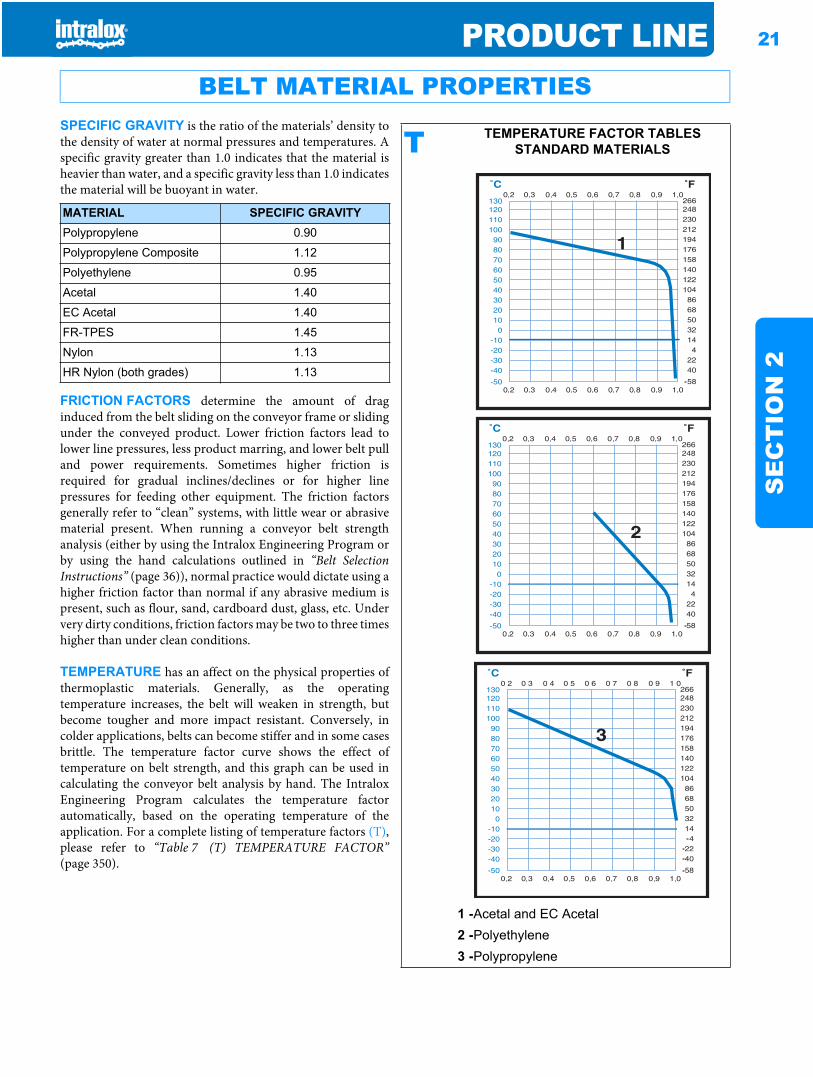
SPECIFIC GRAVITY is the ratio of the materials’ density tothe density of water at normal pressures and temperatures. Aspecific gravity greater than 1.0 indicates that the material isheavier than water, and a specific gravity less than 1.0 indicatesthe material will be buoyant in water.
FRICTION FACTORS determine the amount of draginduced from the belt sliding on the conveyor frame or slidingunder the conveyed product. Lower friction factors lead tolower line pressures, less product marring, and lower belt pulland power requirements. Sometimes higher friction isrequired for gradual inclines/declines or for higher linepressures for feeding other equipment. The friction factorsgenerally refer to “clean” systems, with little wear or abrasivematerial present. When running a conveyor belt strengthanalysis (either by using the Intralox Engineering Program orby using the hand calculations outlined in “Belt SelectionInstructions” (page 36)), normal practice would dictate using ahigher friction factor than normal if any abrasive medium ispresent, such as flour, sand, cardboard dust, glass, etc. Undervery dirty conditions, friction factors may be two to three timeshigher than under clean conditions.
TEMPERATURE has an affect on the physical properties ofthermoplastic materials. Generally, as the operatingtemperature increases, the belt will weaken in strength, butbecome tougher and more impact resistant. Conversely, incolder applications, belts can become stiffer and in some casesbrittle. The temperature factor curve shows the effect oftemperature on belt strength, and this graph can be used incalculating the conveyor belt analysis by hand. The IntraloxEngineering Program calculates the temperature factorautomatically, based on the operating temperature of theapplication. For a complete listing of temperature factors (T),please refer to “Table 7 (T) TEMPERATURE FACTOR”(page 350).
BELT MATERIAL PROPERTIES
MATERIAL SPECIFIC GRAVITYPolypropylene 0.90
Polypropylene Composite 1.12
Polyethylene 0.95
Acetal 1.40
EC Acetal 1.40
FR-TPES 1.45
Nylon 1.13
HR Nylon (both grades) 1.13
T TEMPERATURE FACTOR TABLES STANDARD MATERIALS
1 -Acetal and EC Acetal2 -Polyethylene3 -Polypropylene
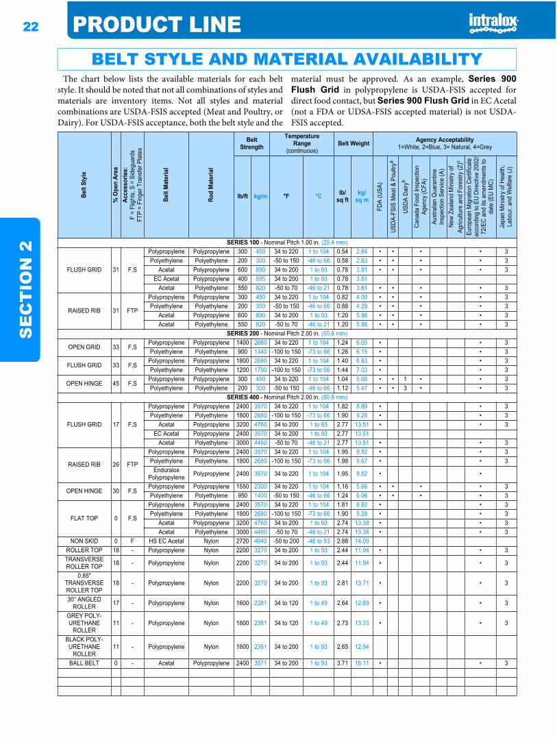
22 PRODUCT LINES
EC
TIO
N 2
The chart below lists the available materials for each beltstyle. It should be noted that not all combinations of styles andmaterials are inventory items. Not all styles and materialcombinations are USDA-FSIS accepted (Meat and Poultry, orDairy). For USDA-FSIS acceptance, both the belt style and the
material must be approved. As an example, Series 900Flush Grid in polypropylene is USDA-FSIS accepted fordirect food contact, but Series 900 Flush Grid in EC Acetal(not a FDA or UDSA-FSIS accepted material) is not USDA-FSIS accepted.
BELT STYLE AND MATERIAL AVAILABILITYBe
lt St
yle
% O
pen
Area
Acce
ssor
ies:
F =
Flig
hts,
S =
Sid
egua
rds
FTP
= Fi
nger
Tra
nsfe
r Pla
tes
Belt
Mat
eria
l
Rod
Mat
eria
l
BeltStrength
TemperatureRange
(continuous)Belt Weight Agency Acceptability
1=White, 2=Blue, 3= Natural, 4=Grey
lb/ft kg/m °F °C lb/sq ft
kg/sq m
FDA
(USA
)
USDA
-FSI
S M
eat &
Pou
ltrya
USDA
Dai
ryb
Cana
da F
ood
Insp
ectio
n Ag
ency
(CFA
)Au
stra
lian
Qua
rant
ine
Insp
ectio
n Se
rvice
(A)
New
Zeal
and
Min
istry
of
Agric
ultu
re a
nd F
ores
try (Z
)c
Euro
pean
Mig
ratio
n Ce
rtific
ate
acco
rdin
g to
EU
Dire
ctive
200
2/72
/EC
and
its a
men
dmen
ts to
da
te (E
U M
C)
Japa
n M
inist
ry o
f Hea
lth,
Labo
ur, a
nd W
elfa
re (J
)
SERIES 100 - Nominal Pitch 1.00 in. (25.4 mm)
FLUSH GRID 31 F,S
Polypropylene Polypropylene 300 450 34 to 220 1 to 104 0.54 2.64 • • • • 3Polyethylene Polyethylene 200 300 -50 to 150 -46 to 66 0.58 2.83 • • • • 3
Acetal Polypropylene 600 890 34 to 200 1 to 93 0.78 3.81 • • • • 3EC Acetal Polypropylene 400 595 34 to 200 1 to 93 0.78 3.81
Acetal Polyethylene 550 820 -50 to 70 -46 to 21 0.78 3.81 • • • • 3
RAISED RIB 31 FTP
Polypropylene Polypropylene 300 450 34 to 220 1 to 104 0.82 4.00 • • • • 3Polyethylene Polyethylene 200 300 -50 to 150 -46 to 66 0.88 4.29 • • • • 3
Acetal Polypropylene 600 890 34 to 200 1 to 93 1.20 5.86 • • • • 3Acetal Polyethylene 550 820 -50 to 70 -46 to 21 1.20 5.86 • • • • 3
SERIES 200 - Nominal Pitch 2.00 in. (50.8 mm)
OPEN GRID 33 F,SPolypropylene Polypropylene 1400 2080 34 to 220 1 to 104 1.24 6.05 • • 3Polyethylene Polyethylene 900 1340 -100 to 150 -73 to 66 1.26 6.15 • • 3
FLUSH GRID 33 F,SPolypropylene Polypropylene 1800 2680 34 to 220 1 to 104 1.40 6.83 • • 3Polyethylene Polyethylene 1200 1790 -100 to 150 -73 to 66 1.44 7.03 • • 3
OPEN HINGE 45 F,SPolypropylene Polypropylene 300 450 34 to 220 1 to 104 1.04 5.08 • • 1 • • 3Polyethylene Polyethylene 200 300 -50 to 150 -46 to 66 1.12 5.47 • • 3 • • 3
SERIES 400 - Nominal Pitch 2.00 in. (50.8 mm)
FLUSH GRID 17 F,S
Polypropylene Polypropylene 2400 3570 34 to 220 1 to 104 1.82 8.89 • • 3Polyethylene Polyethylene 1800 2680 -100 to 150 -73 to 66 1.90 9.28 • • 3
Acetal Polypropylene 3200 4760 34 to 200 1 to 93 2.77 13.51 • • 3EC Acetal Polypropylene 2400 3570 34 to 200 1 to 93 2.77 13.51
Acetal Polyethylene 3000 4460 -50 to 70 -46 to 21 2.77 13.51 • • 3
RAISED RIB 26 FTP
Polypropylene Polypropylene 2400 3570 34 to 220 1 to 104 1.95 9.52 • • 3Polyethylene Polyethylene 1800 2680 -100 to 150 -73 to 66 1.98 9.67 • • 3
Enduralox Polypropylene Polypropylene 2400 3570 34 to 220 1 to 104 1.95 9.52 • •
OPEN HINGE 30 F,SPolypropylene Polypropylene 1550 2300 34 to 220 1 to 104 1.16 5.66 • • • • 3Polyethylene Polyethylene 950 1400 -50 to 150 -46 to 66 1.24 6.06 • • • • 3
FLAT TOP 0 F,S
Polypropylene Polypropylene 2400 3570 34 to 220 1 to 104 1.81 8.82 • • 3Polyethylene Polyethylene 1800 2680 -100 to 150 -73 to 66 1.90 9.28 • • 3
Acetal Polypropylene 3200 4760 34 to 200 1 to 93 2.74 13.38 • • 3Acetal Polyethylene 3000 4460 -50 to 70 -46 to 21 2.74 13.38 • • 3
NON SKID 0 F HS EC Acetal Nylon 2720 4040 -50 to 200 -46 to 93 2.88 14.09ROLLER TOP 18 - Polypropylene Nylon 2200 3270 34 to 200 1 to 93 2.44 11.94 • • 3TRANSVERSE ROLLER TOP 18 - Polypropylene Nylon 2200 3270 34 to 200 1 to 93 2.44 11.94 • • 3
0.85" TRANSVERSE ROLLER TOP
18 - Polypropylene Nylon 2200 3270 34 to 200 1 to 93 2.81 13.71 • • 3
30° ANGLED ROLLER 17 - Polypropylene Nylon 1600 2381 34 to 120 1 to 49 2.64 12.89 • • 3
GREY POLY-URETHANE
ROLLER11 - Polypropylene Nylon 1600 2381 34 to 120 1 to 49 2.73 13.33 • • 3
BLACK POLY-URETHANE
ROLLER11 - Polypropylene Nylon 1600 2381 34 to 200 1 to 93 2.65 12.94
BALL BELT 0 - Acetal Polypropylene 2400 3571 34 to 200 1 to 93 3.71 18.11 • • 3
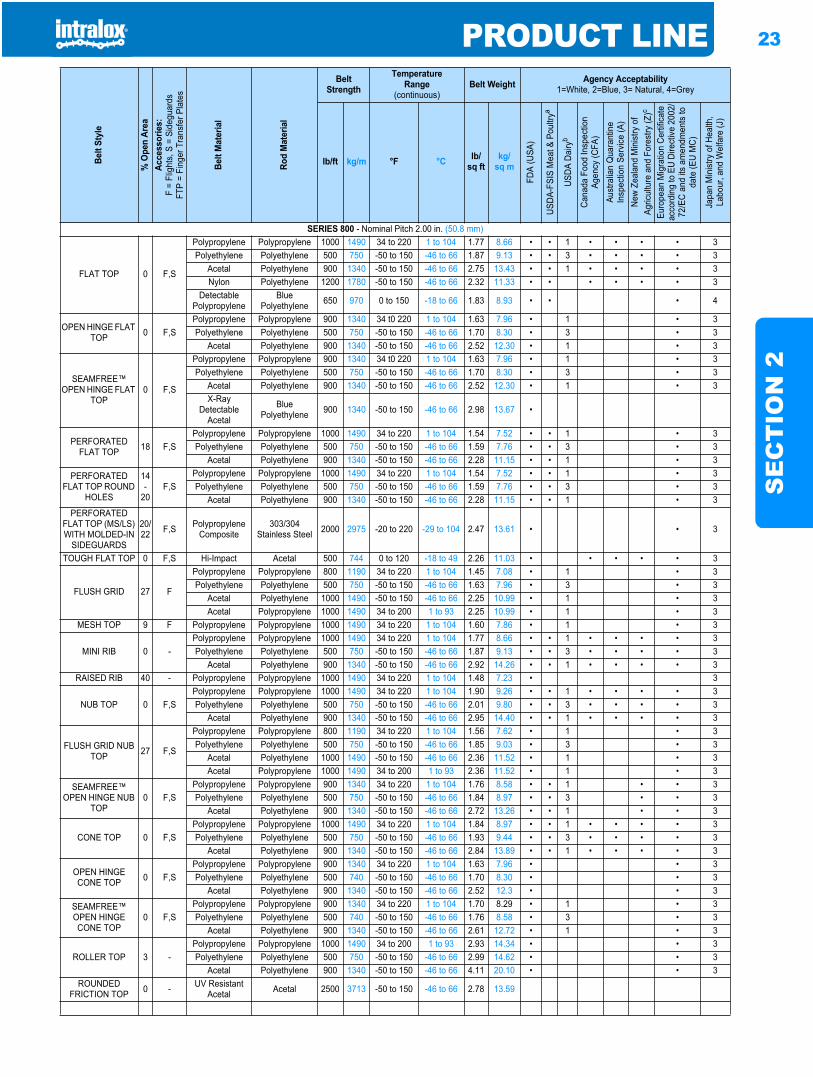
PRODUCT LINE 23
SE
CT
ION
2
SERIES 800 - Nominal Pitch 2.00 in. (50.8 mm)
FLAT TOP 0 F,S
Polypropylene Polypropylene 1000 1490 34 to 220 1 to 104 1.77 8.66 • • 1 • • • • 3Polyethylene Polyethylene 500 750 -50 to 150 -46 to 66 1.87 9.13 • • 3 • • • • 3
Acetal Polyethylene 900 1340 -50 to 150 -46 to 66 2.75 13.43 • • 1 • • • • 3Nylon Polyethylene 1200 1780 -50 to 150 -46 to 66 2.32 11.33 • • • • • • 3
Detectable Polypropylene
BluePolyethylene 650 970 0 to 150 -18 to 66 1.83 8.93 • • • 4
OPEN HINGE FLAT TOP 0 F,S
Polypropylene Polypropylene 900 1340 34 t0 220 1 to 104 1.63 7.96 • 1 • 3Polyethylene Polyethylene 500 750 -50 to 150 -46 to 66 1.70 8.30 • 3 • 3
Acetal Polyethylene 900 1340 -50 to 150 -46 to 66 2.52 12.30 • 1 • 3
SEAMFREE™ OPEN HINGE FLAT
TOP0 F,S
Polypropylene Polypropylene 900 1340 34 t0 220 1 to 104 1.63 7.96 • 1 • 3Polyethylene Polyethylene 500 750 -50 to 150 -46 to 66 1.70 8.30 • 3 • 3
Acetal Polyethylene 900 1340 -50 to 150 -46 to 66 2.52 12.30 • 1 • 3X-Ray
Detectable Acetal
BluePolyethylene 900 1340 -50 to 150 -46 to 66 2.98 13.67 •
PERFORATED FLAT TOP 18 F,S
Polypropylene Polypropylene 1000 1490 34 to 220 1 to 104 1.54 7.52 • • 1 • 3Polyethylene Polyethylene 500 750 -50 to 150 -46 to 66 1.59 7.76 • • 3 • 3
Acetal Polyethylene 900 1340 -50 to 150 -46 to 66 2.28 11.15 • • 1 • 3
PERFORATED FLAT TOP ROUND
HOLES
14-
20F,S
Polypropylene Polypropylene 1000 1490 34 to 220 1 to 104 1.54 7.52 • • 1 • 3Polyethylene Polyethylene 500 750 -50 to 150 -46 to 66 1.59 7.76 • • 3 • 3
Acetal Polyethylene 900 1340 -50 to 150 -46 to 66 2.28 11.15 • • 1 • 3PERFORATED
FLAT TOP (MS/LS) WITH MOLDED-IN
SIDEGUARDS
20/22 F,S Polypropylene
Composite303/304
Stainless Steel 2000 2975 -20 to 220 -29 to 104 2.47 13.61 • • 3
TOUGH FLAT TOP 0 F,S Hi-Impact Acetal 500 744 0 to 120 -18 to 49 2.26 11.03 • • • • • 3
FLUSH GRID 27 F
Polypropylene Polypropylene 800 1190 34 to 220 1 to 104 1.45 7.08 • 1 • 3Polyethylene Polyethylene 500 750 -50 to 150 -46 to 66 1.63 7.96 • 3 • 3
Acetal Polyethylene 1000 1490 -50 to 150 -46 to 66 2.25 10.99 • 1 • 3Acetal Polypropylene 1000 1490 34 to 200 1 to 93 2.25 10.99 • 1 • 3
MESH TOP 9 F Polypropylene Polypropylene 1000 1490 34 to 220 1 to 104 1.60 7.86 • 1 • 3
MINI RIB 0 -Polypropylene Polypropylene 1000 1490 34 to 220 1 to 104 1.77 8.66 • • 1 • • • • 3Polyethylene Polyethylene 500 750 -50 to 150 -46 to 66 1.87 9.13 • • 3 • • • • 3
Acetal Polyethylene 900 1340 -50 to 150 -46 to 66 2.92 14.26 • • 1 • • • • 3RAISED RIB 40 - Polypropylene Polypropylene 1000 1490 34 to 220 1 to 104 1.48 7.23 • 3
NUB TOP 0 F,SPolypropylene Polypropylene 1000 1490 34 to 220 1 to 104 1.90 9.26 • • 1 • • • • 3Polyethylene Polyethylene 500 750 -50 to 150 -46 to 66 2.01 9.80 • • 3 • • • • 3
Acetal Polyethylene 900 1340 -50 to 150 -46 to 66 2.95 14.40 • • 1 • • • • 3
FLUSH GRID NUB TOP 27 F,S
Polypropylene Polypropylene 800 1190 34 to 220 1 to 104 1.56 7.62 • 1 • 3Polyethylene Polyethylene 500 750 -50 to 150 -46 to 66 1.85 9.03 • 3 • 3
Acetal Polyethylene 1000 1490 -50 to 150 -46 to 66 2.36 11.52 • 1 • 3Acetal Polypropylene 1000 1490 34 to 200 1 to 93 2.36 11.52 • 1 • 3
SEAMFREE™ OPEN HINGE NUB
TOP0 F,S
Polypropylene Polypropylene 900 1340 34 to 220 1 to 104 1.76 8.58 • • 1 • • 3Polyethylene Polyethylene 500 750 -50 to 150 -46 to 66 1.84 8.97 • • 3 • • 3
Acetal Polyethylene 900 1340 -50 to 150 -46 to 66 2.72 13.26 • • 1 • • 3
CONE TOP 0 F,SPolypropylene Polypropylene 1000 1490 34 to 220 1 to 104 1.84 8.97 • • 1 • • • • 3Polyethylene Polyethylene 500 750 -50 to 150 -46 to 66 1.93 9.44 • • 3 • • • • 3
Acetal Polyethylene 900 1340 -50 to 150 -46 to 66 2.84 13.89 • • 1 • • • • 3
OPEN HINGE CONE TOP 0 F,S
Polypropylene Polypropylene 900 1340 34 to 220 1 to 104 1.63 7.96 • • 3Polyethylene Polyethylene 500 740 -50 to 150 -46 to 66 1.70 8.30 • • 3
Acetal Polyethylene 900 1340 -50 to 150 -46 to 66 2.52 12.3 • • 3
SEAMFREE™ OPEN HINGE CONE TOP
0 F,SPolypropylene Polypropylene 900 1340 34 to 220 1 to 104 1.70 8.29 • 1 • 3Polyethylene Polyethylene 500 740 -50 to 150 -46 to 66 1.76 8.58 • 3 • 3
Acetal Polyethylene 900 1340 -50 to 150 -46 to 66 2.61 12.72 • 1 • 3
ROLLER TOP 3 -Polypropylene Polypropylene 1000 1490 34 to 200 1 to 93 2.93 14.34 • • 3Polyethylene Polyethylene 500 750 -50 to 150 -46 to 66 2.99 14.62 • • 3
Acetal Polyethylene 900 1340 -50 to 150 -46 to 66 4.11 20.10 • • 3ROUNDED
FRICTION TOP 0 - UV Resistant Acetal Acetal 2500 3713 -50 to 150 -46 to 66 2.78 13.59
Belt
Styl
e
% O
pen
Area
Acce
ssor
ies:
F =
Flig
hts,
S =
Sid
egua
rds
FTP
= Fi
nger
Tra
nsfe
r Pla
tes
Belt
Mat
eria
l
Rod
Mat
eria
l
BeltStrength
TemperatureRange
(continuous)Belt Weight Agency Acceptability
1=White, 2=Blue, 3= Natural, 4=Grey
lb/ft kg/m °F °C lb/sq ft
kg/sq m
FDA
(USA
)
USDA
-FSI
S M
eat &
Pou
ltrya
USDA
Dai
ryb
Cana
da F
ood
Insp
ectio
n Ag
ency
(CFA
)Au
stra
lian
Qua
rant
ine
Insp
ectio
n Se
rvice
(A)
New
Zeal
and
Min
istry
of
Agric
ultu
re a
nd F
ores
try (Z
)c
Euro
pean
Mig
ratio
n Ce
rtific
ate
acco
rdin
g to
EU
Dire
ctive
200
2/72
/EC
and
its a
men
dmen
ts to
da
te (E
U M
C)
Japa
n M
inist
ry o
f Hea
lth,
Labo
ur, a
nd W
elfa
re (J
)
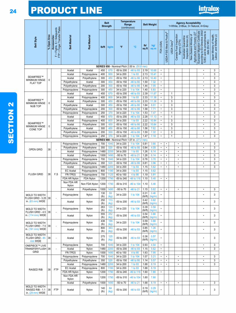
24 PRODUCT LINES
EC
TIO
N 2
SERIES 850 - Nominal Pitch 2.00 in. (50.8 mm)
SEAMFREE™ MINIMUM HINGE
FLAT TOP0
Acetal Acetal 450 670 -50 to 200 -46 to 93 2.19 10.68 • • 3Acetal Polypropylene 400 600 34 to 200 1 to 93 2.13 10.41 • • 3Acetal Polyethylene 300 450 -50 to 150 -46 to 66 2.13 10.40 • • 3
Polyethylene Acetal 300 450 -50 to 150 -46 to 66 1.50 7.32 • • 3Polyethylene Polyethylene 200 300 -50 to 150 -46 to 66 1.44 7.05 • • 3
Polypropylene Polypropylene 300 450 34 to 220 1 to 104 1.40 6.83 • • 3
SEAMFREE™ MINIMUM HINGE
NUB TOP0
Acetal Acetal 450 670 -50 to 200 -46 to 93 2.39 11.67 • 1 • 3Acetal Polypropylene 400 600 34 to 200 1 to 93 2.33 11.38 • 3 • 3Acetal Polyethylene 300 450 -50 to 150 -46 to 66 2.33 11.38 • 3 • 3
Polyethylene Acetal 300 450 -50 to 150 -46 to 66 1.64 8.01 • 3 • 3Polyethylene Polypropylene 200 300 -50 to 150 -46 to 66 1.58 7.71 • 3 • 3
Polypropylene Polypropylene 250 370 34 to 220 1 to 104 1.53 7.47 • 1 • 3
SEAMFREE™ MINIMUM HINGE
CONE TOP0
Acetal Acetal 450 670 -50 to 200 -46 to 93 2.28 11.13 • 1 • 3Acetal Polypropylene 400 600 34 to 200 1 to 93 2.22 10.84 • 3 • 3Acetal Polyethylene 300 450 -50 to 150 -46 to 66 2.22 10.84 • 3 • 3
Polyethylene Acetal 300 450 -50 to 150 -46 to 66 1.56 7.62 • 3 • 3Polyethylene Polypropylene 200 300 -50 to 150 -46 to 66 1.50 7.32 • 3 • 3
Polypropylene Polypropylene 250 370 34 to 220 1 to 104 1.47 7.18 • 1 • 3SERIES 900 - Nominal Pitch 1.07 in. (27.2 mm)
OPEN GRID 38 -
Polypropylene Polypropylene 700 1040 34 to 220 1 to 104 0.81 3.95 • • • • 3Polyethylene Polyethylene 350 520 -50 to 150 -46 to 66 0.84 4.09 • • • • 3
Acetal Polypropylene 1480 2200 34 to 200 1 to 93 1.26 6.14 • • • • 3Acetal Polyethylene 1000 1490 -50 to 70 -46 to 21 1.26 6.14 • • • • 3
FLUSH GRID 38 F,S
Polypropylene Polypropylene 700 1040 34 to 220 1 to 104 0.76 3.70 • • • • 3Polyethylene Polyethylene 350 520 -50 to 150 -46 to 66 0.81 3.96 • • • • 3
Acetal Polypropylene 1480 2200 34 to 200 1 to 93 1.15 5.62 • • • • 3EC Acetal Polypropylene 800 1190 34 to 200 1 to 93 1.15 5.62FR-TPES Polypropylene 750 1120 40 to 150 4 to 66 1.19 5.81
FDA HR Nylon FDA Nylon 1200 1790 -50 to 240 -46 to 116 1.10 5.40 • •Non FDA HR
Nylon Non FDA Nylon 1200 1790 -50 to 310 -46 to 154 1.10 5.40
Acetal Polyethylene 1000 1490 -50 to 70 -46 to 21 1.15 5.62 • • • • 3
MOLD TO WIDTH FLUSH GRID - 3.25 in. (83 mm) WIDE
38 -Polypropylene Nylon 130
(lb)59
(kg) 34 to 220 1 to 104 0.31 (lb/ft)
0.46 (kg/m) • • 3
Acetal Nylon 250(lb)
113 (kg) -50 to 200 -46 to 93 0.42
(lb/ft)0.62
(kg/m) • • 3
MOLD TO WIDTH FLUSH GRID - 4.5 in. (114 mm) WIDE
38 -Polypropylene Nylon 263
(lb)120 (kg) 34 to 220 1 to 104 0.39
(lb/ft)0.58
(kg/m) • • 3
Acetal Nylon 555(lb)
252 (kg) -50 to 200 -46 to 93 0.54
(lb/ft)0.80
(kg/m) • • 3
MOLD TO WIDTH FLUSH GRID - 7.5 in. (191 mm) WIDE
38 -Polypropylene Nylon 438
(lb)199 (kg) 34 to 220 1 to 104 0.59
(lb/ft)0.88
(kg/m) • • 3
Acetal Nylon 800(lb)
363 (kg) -50 to 200 -46 to 93 0.85
(lb/ft)1.26
(kg/m) • • 3
MOLD TO WIDTH FLUSH GRID - 85
mm WIDE38 - Acetal Nylon 275
(lb)125 (kg) -50 to 200 -46 to 93 0.38
(lb/ft)0.57
(kg/m) • • 3
ONEPIECE™ LIVE TRANSFER FLUSH
GRID38 -
Polypropylene Nylon 700 1040 34 to 220 1 to 104 0.93 4.54 • • 3Acetal Nylon 1480 2200 -50 to 200 -46 to 93 1.15 5.62 • • 3
FR-TPES Nylon 1000 1490 40 to 150 4 to 66 1.63 7.95 •
RAISED RIB 38 FTP
Polypropylene Polypropylene 700 1040 34 to 220 1 to 104 1.07 5.21 • • • • 3Polyethylene Polyethylene 350 520 -50 to 150 -46 to 66 1.14 5.57 • • • • 3
Acetal Polypropylene 1480 2200 34 to 200 1 to 93 1.68 8.19 • • • • 3EC Acetal Polypropylene 800 1190 34 to 200 1 to 93 1.68 8.19
FDA HR Nylon Nylon 1200 1790 -50 to 240 -46 to 116 1.60 7.80 •Non FDA HR
Nylon Nylon 1200 1790 -50 to 310 -46 to 154 1.60 7.80
Acetal Polyethylene 1000 1490 -50 to 70 -46 to 21 1.68 8.19 • • • • 3MOLD TO WIDTH RAISED RIB - 1.1 in. (29 mm) WIDE
38 FTP Acetal Nylon 140(lb)
64 (kg) -50 to 200 -46 to 93 0.19
(lb/ft)0.29
(kg/m) • • 3
Belt
Styl
e
% O
pen
Area
Acce
ssor
ies:
F =
Flig
hts,
S =
Sid
egua
rds
FTP
= Fi
nger
Tra
nsfe
r Pla
tes
Belt
Mat
eria
l
Rod
Mat
eria
l
BeltStrength
TemperatureRange
(continuous)Belt Weight Agency Acceptability
1=White, 2=Blue, 3= Natural, 4=Grey
lb/ft kg/m °F °C lb/sq ft
kg/sq m
FDA
(USA
)
USDA
-FSI
S M
eat &
Pou
ltrya
USDA
Dai
ryb
Cana
da F
ood
Insp
ectio
n Ag
ency
(CFA
)Au
stra
lian
Qua
rant
ine
Insp
ectio
n Se
rvice
(A)
New
Zeal
and
Min
istry
of
Agric
ultu
re a
nd F
ores
try (Z
)c
Euro
pean
Mig
ratio
n Ce
rtific
ate
acco
rdin
g to
EU
Dire
ctive
200
2/72
/EC
and
its a
men
dmen
ts to
da
te (E
U M
C)
Japa
n M
inist
ry o
f Hea
lth,
Labo
ur, a
nd W
elfa
re (J
)
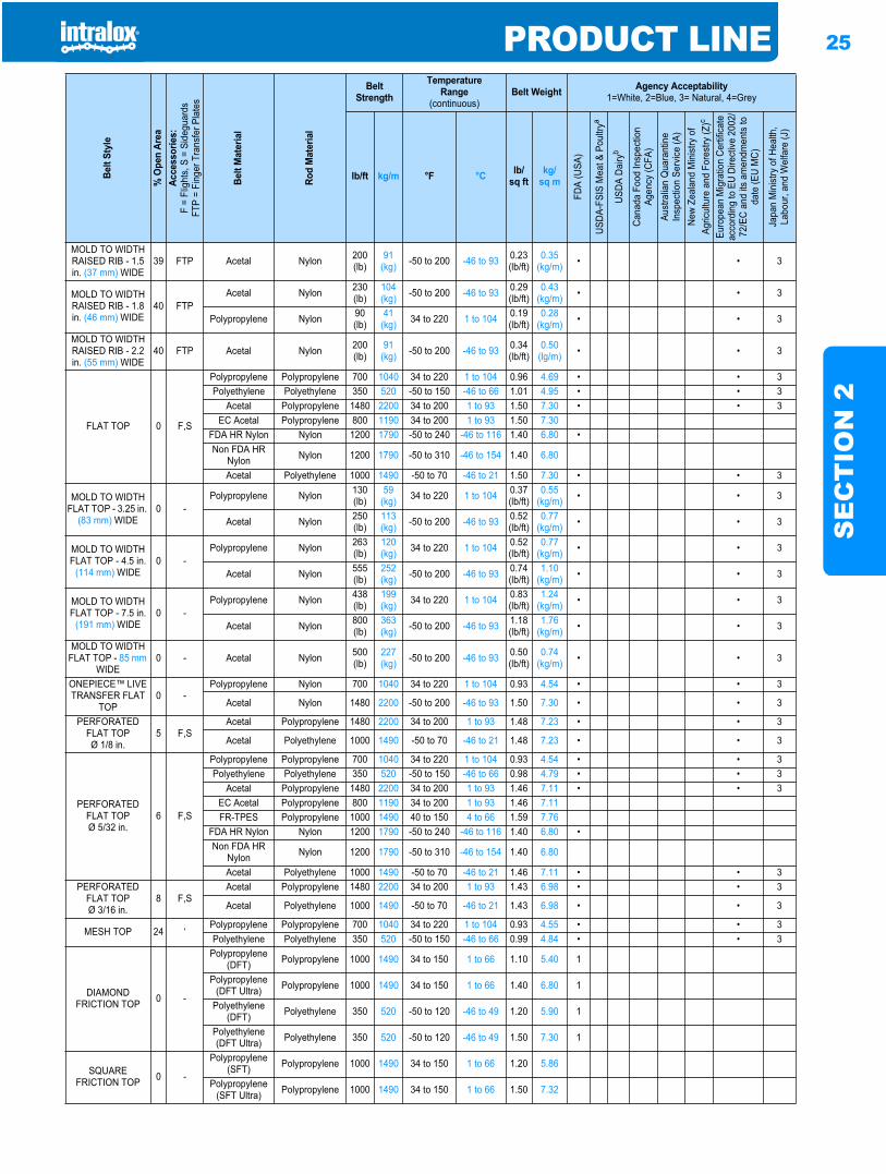
PRODUCT LINE 25
SE
CT
ION
2
MOLD TO WIDTH RAISED RIB - 1.5 in. (37 mm) WIDE
39 FTP Acetal Nylon 200(lb)
91 (kg) -50 to 200 -46 to 93 0.23
(lb/ft)0.35
(kg/m) • • 3
MOLD TO WIDTH RAISED RIB - 1.8 in. (46 mm) WIDE
40 FTPAcetal Nylon 230
(lb)104 (kg) -50 to 200 -46 to 93 0.29
(lb/ft)0.43
(kg/m) • • 3
Polypropylene Nylon 90(lb)
41 (kg) 34 to 220 1 to 104 0.19
(lb/ft)0.28
(kg/m) • • 3
MOLD TO WIDTH RAISED RIB - 2.2 in. (55 mm) WIDE
40 FTP Acetal Nylon 200(lb)
91 (kg) -50 to 200 -46 to 93 0.34
(lb/ft)0.50
(lg/m) • • 3
FLAT TOP 0 F,S
Polypropylene Polypropylene 700 1040 34 to 220 1 to 104 0.96 4.69 • • 3Polyethylene Polyethylene 350 520 -50 to 150 -46 to 66 1.01 4.95 • • 3
Acetal Polypropylene 1480 2200 34 to 200 1 to 93 1.50 7.30 • • 3EC Acetal Polypropylene 800 1190 34 to 200 1 to 93 1.50 7.30
FDA HR Nylon Nylon 1200 1790 -50 to 240 -46 to 116 1.40 6.80 •Non FDA HR
Nylon Nylon 1200 1790 -50 to 310 -46 to 154 1.40 6.80
Acetal Polyethylene 1000 1490 -50 to 70 -46 to 21 1.50 7.30 • • 3
MOLD TO WIDTH FLAT TOP - 3.25 in.
(83 mm) WIDE0 -
Polypropylene Nylon 130(lb)
59 (kg) 34 to 220 1 to 104 0.37
(lb/ft)0.55
(kg/m) • • 3
Acetal Nylon 250(lb)
113 (kg) -50 to 200 -46 to 93 0.52
(lb/ft)0.77
(kg/m) • • 3
MOLD TO WIDTH FLAT TOP - 4.5 in.
(114 mm) WIDE0 -
Polypropylene Nylon 263(lb)
120 (kg) 34 to 220 1 to 104 0.52
(lb/ft)0.77
(kg/m) • • 3
Acetal Nylon 555(lb)
252 (kg) -50 to 200 -46 to 93 0.74
(lb/ft)1.10
(kg/m) • • 3
MOLD TO WIDTH FLAT TOP - 7.5 in.
(191 mm) WIDE0 -
Polypropylene Nylon 438(lb)
199 (kg) 34 to 220 1 to 104 0.83
(lb/ft)1.24
(kg/m) • • 3
Acetal Nylon 800(lb)
363 (kg) -50 to 200 -46 to 93 1.18
(lb/ft)1.76
(kg/m) • • 3
MOLD TO WIDTH FLAT TOP - 85 mm
WIDE0 - Acetal Nylon 500
(lb)227 (kg) -50 to 200 -46 to 93 0.50
(lb/ft)0.74
(kg/m) • • 3
ONEPIECE™ LIVE TRANSFER FLAT
TOP0 -
Polypropylene Nylon 700 1040 34 to 220 1 to 104 0.93 4.54 • • 3
Acetal Nylon 1480 2200 -50 to 200 -46 to 93 1.50 7.30 • • 3
PERFORATED FLAT TOPØ 1/8 in.
5 F,SAcetal Polypropylene 1480 2200 34 to 200 1 to 93 1.48 7.23 • • 3
Acetal Polyethylene 1000 1490 -50 to 70 -46 to 21 1.48 7.23 • • 3
PERFORATED FLAT TOPØ 5/32 in.
6 F,S
Polypropylene Polypropylene 700 1040 34 to 220 1 to 104 0.93 4.54 • • 3Polyethylene Polyethylene 350 520 -50 to 150 -46 to 66 0.98 4.79 • • 3
Acetal Polypropylene 1480 2200 34 to 200 1 to 93 1.46 7.11 • • 3EC Acetal Polypropylene 800 1190 34 to 200 1 to 93 1.46 7.11FR-TPES Polypropylene 1000 1490 40 to 150 4 to 66 1.59 7.76
FDA HR Nylon Nylon 1200 1790 -50 to 240 -46 to 116 1.40 6.80 •Non FDA HR
Nylon Nylon 1200 1790 -50 to 310 -46 to 154 1.40 6.80
Acetal Polyethylene 1000 1490 -50 to 70 -46 to 21 1.46 7.11 • • 3PERFORATED
FLAT TOPØ 3/16 in.
8 F,SAcetal Polypropylene 1480 2200 34 to 200 1 to 93 1.43 6.98 • • 3
Acetal Polyethylene 1000 1490 -50 to 70 -46 to 21 1.43 6.98 • • 3
MESH TOP 24 ‘Polypropylene Polypropylene 700 1040 34 to 220 1 to 104 0.93 4.55 • • 3Polyethylene Polyethylene 350 520 -50 to 150 -46 to 66 0.99 4.84 • • 3
DIAMOND FRICTION TOP 0 -
Polypropylene (DFT) Polypropylene 1000 1490 34 to 150 1 to 66 1.10 5.40 1
Polypropylene (DFT Ultra) Polypropylene 1000 1490 34 to 150 1 to 66 1.40 6.80 1
Polyethylene (DFT) Polyethylene 350 520 -50 to 120 -46 to 49 1.20 5.90 1
Polyethylene (DFT Ultra) Polyethylene 350 520 -50 to 120 -46 to 49 1.50 7.30 1
SQUARE FRICTION TOP 0 -
Polypropylene (SFT) Polypropylene 1000 1490 34 to 150 1 to 66 1.20 5.86
Polypropylene (SFT Ultra) Polypropylene 1000 1490 34 to 150 1 to 66 1.50 7.32
Belt
Styl
e
% O
pen
Area
Acce
ssor
ies:
F =
Flig
hts,
S =
Sid
egua
rds
FTP
= Fi
nger
Tra
nsfe
r Pla
tes
Belt
Mat
eria
l
Rod
Mat
eria
l
BeltStrength
TemperatureRange
(continuous)Belt Weight Agency Acceptability
1=White, 2=Blue, 3= Natural, 4=Grey
lb/ft kg/m °F °C lb/sq ft
kg/sq m
FDA
(USA
)
USDA
-FSI
S M
eat &
Pou
ltrya
USDA
Dai
ryb
Cana
da F
ood
Insp
ectio
n Ag
ency
(CFA
)Au
stra
lian
Qua
rant
ine
Insp
ectio
n Se
rvice
(A)
New
Zeal
and
Min
istry
of
Agric
ultu
re a
nd F
ores
try (Z
)c
Euro
pean
Mig
ratio
n Ce
rtific
ate
acco
rdin
g to
EU
Dire
ctive
200
2/72
/EC
and
its a
men
dmen
ts to
da
te (E
U M
C)
Japa
n M
inist
ry o
f Hea
lth,
Labo
ur, a
nd W
elfa
re (J
)
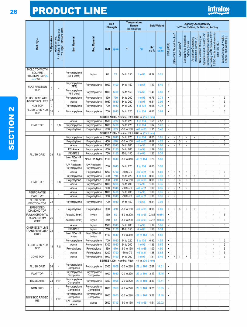
26 PRODUCT LINES
EC
TIO
N 2
MOLD TO WIDTH SQUARE
FRICTION TOP 29mm WIDE
0 Polypropylene (SFT Ultra) Nylon 65 29 34 to 150 1 to 66 0.17 0.25
FLAT FRICTION TOP 0 -
Polypropylene (FFT) Polypropylene 1000 1490 34 to 150 1 to 66 1.10 5.40 1
Polypropylene (FFT Ultra) Polypropylene 1000 1490 34 to 150 1 to 66 1.40 6.80 1
FLUSH GRID WITH INSERT ROLLERS 38 -
Polypropylene Polypropylene 490 730 34 to 200 1 to 93 0.76 3.71 • • 3Acetal Polypropylene 1030 1530 34 to 200 1 to 93 0.81 3.95 • • 3
NUB TOP 0 Polypropylene Polypropylene 700 1040 34 to 220 1 to 104 0.98 4.78 • • 3FLUSH GRID NUB
TOP 38 - Polypropylene Polypropylene 700 1040 34 to 220 1 to 104 0.80 3.91 • • 3
SERIES 1000 - Nominal Pitch 0.60 in. (15.2 mm)
FLAT TOP 0 F,SAcetal Polypropylene 1500 2232 34 to 220 1 to 104 1.55 7.57 • 3
Polypropylene Polypropylene 1000 1490 34 to 220 1 to 104 1.07 5.22 • 3Polyethylene Polyethylene 600 893 -50 to 150 -46 to 66 1.11 5.42 • 3
SERIES 1100 - Nominal Pitch 0.60 in. (15.2 mm)
FLUSH GRID 28 F,S
Polypropylene Polypropylene 700 1040 34 to 220 1 to 104 0.81 3.95 • • 1 • • • 3Polyethylene Polyethylene 450 670 -50 to 150 -46 to 66 0.87 4.25 • • 3 • • 3
Acetal Polypropylene 1300 1940 34 to 200 1 to 93 1.19 5.80 • • 1 • • 3EC Acetal Polypropylene 800 1190 34 to 200 1 to 93 1.19 5.80FR-TPES Polypropylene 750 1120 40 to 150 4 to 66 1.30 6.34
Non FDA HR Nylon Non FDA Nylon 1100 1640 -50 to 310 -46 to 154 1.20 5.80
UV Resistant Polypropylene
UV Resistant Polypropylene 700 1040 34 to 220 1 to 104 0.81 3.98
Acetal Polyethylene 1200 1790 -50 to 70 -46 to 21 1.19 5.80 • • 1 • • 3
FLAT TOP 0 F,S
Polypropylene Polypropylene 500 750 34 to 220 1 to 104 0.90 4.40 • • 1 • • • 3Polyethylene Polyethylene 300 450 -50 to 150 -46 to 66 0.96 4.69 • • 3 • • • 3
Acetal Polypropylene 1000 1490 34 to 200 1 to 93 1.30 6.35 • • 1 • • 3Acetal Polyethylene 900 1340 -50 to 70 -46 to 21 1.30 6.35 • • 1 • • 3
PERFORATED FLAT TOP 3 -
Acetal Polypropylene 1000 1490 34 to 200 1 to 93 1.30 6.35 • • • 3Acetal Polyethylene 900 1340 -50 to 70 -46 to 21 1.30 6.35 • • • 3
FLUSH GRID FRICTION TOP 28 - Polypropylene Polypropylene 700 1040 34 to 150 1 to 66 0.81 3.98 1
EMBEDDED DIAMOND TOP 0 - Polyethylene Polyethylene 300 450 -50 to 150 -46 to 66 0.96 4.69 • • 3 • • • 3
FLUSH GRID MTW 38 AND 46 MM
WIDE26 -
Acetal (38mm) Nylon 130 59 -50 to 200 -46 to 93 0.185 0.084 • • 3
Acetal (46mm) Nylon 150 68 -50 to 200 -46 to 93 0.216 0.098 • • 3
ONEPIECE™ LIVE TRANSFER FLUSH
GRID28 -
Acetal Nylon 1300 1940 34 to 200 1 to 93 1.19 5.80 • • 3FR-TPES Nylon 750 1120 40 to 150 4 to 66 1.30 6.34
Non FDA HR Nylon
Non FDA HR Nylon 1100 1640 -50 to 310 -46 to 154 1.20 5.80
FLUSH GRID NUB TOP 15 F,S
Polypropylene Polypropylene 700 1040 34 to 220 1 to 104 0.93 4.55 • • 3Acetal Polypropylene 1300 1940 34 to 200 1 to 93 1.36 6.65 • • 3
Polyethylene Polyethylene 450 670 -50 to 150 -46 to 66 1.00 4.90 • • 3Acetal Polyethylene 1200 1790 -50 to 70 -46 to 21 1.36 6.65 • • 3
CONE TOP 0 - Acetal Polypropylene 1000 1490 34 to 200 1 to 93 1.31 6.40 • • 1 • • 3SERIES 1200 - Nominal Pitch 1.44 in. (36.6 mm)
FLUSH GRID 24 - Polypropylene Composite Polypropylene 3300 4908 -20 to 220 -29 to 104 2.87 14.01 •
FLAT TOP 0 - Polypropylene Composite
Polypropylene Composite 4000 5950 -20 to 220 -29 to 104 3.17 15.45 •
RAISED RIB 24 FTP Polypropylene Composite Polypropylene 3300 4908 -20 to 220 -29 to 104 3.30 16.11 •
NON SKID 0 - Polypropylene Composite
Polypropylene Composite 4000 5950 -20 to 220 -29 to 104 3.21 15.65 •
NON SKID RAISED RIB 0 FTP
Polypropylene Composite
Polypropylene Composite 4000 5950 -20 to 220 -29 to 104 3.58 17.48 •
UV Resistant Acetal Acetal 2500 3713 -50 to 150 -46 to 66 4.51 22.02
Belt
Styl
e
% O
pen
Area
Acce
ssor
ies:
F =
Flig
hts,
S =
Sid
egua
rds
FTP
= Fi
nger
Tra
nsfe
r Pla
tes
Belt
Mat
eria
l
Rod
Mat
eria
l
BeltStrength
TemperatureRange
(continuous)Belt Weight Agency Acceptability
1=White, 2=Blue, 3= Natural, 4=Grey
lb/ft kg/m °F °C lb/sq ft
kg/sq m
FDA
(USA
)
USDA
-FSI
S M
eat &
Pou
ltrya
USDA
Dai
ryb
Cana
da F
ood
Insp
ectio
n Ag
ency
(CFA
)Au
stra
lian
Qua
rant
ine
Insp
ectio
n Se
rvice
(A)
New
Zeal
and
Min
istry
of
Agric
ultu
re a
nd F
ores
try (Z
)c
Euro
pean
Mig
ratio
n Ce
rtific
ate
acco
rdin
g to
EU
Dire
ctive
200
2/72
/EC
and
its a
men
dmen
ts to
da
te (E
U M
C)
Japa
n M
inist
ry o
f Hea
lth,
Labo
ur, a
nd W
elfa
re (J
)
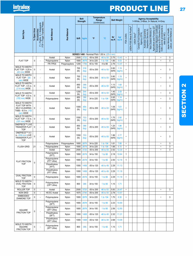
PRODUCT LINE 27
SE
CT
ION
2
SERIES 1400 - Nominal Pitch 1.00 in. (25.4 mm)
FLAT TOP 0 -Acetal Nylon 2500 3720 -50 to 200 -46 to 93 2.75 13.43 • • 3
Polypropylene Nylon 1800 2678 34 to 220 1 to 104 1.85 9.03 • • 3FR-TPES Polypropylene 1200 1786 40 to 150 4 to 66 2.76 13.47 •
MOLD TO WIDTH FLAT TOP - 3.25 in.
(83 mm) WIDE0 - Acetal Nylon 700
(lb)318 (kg) -50 to 200 -46 to 93 0.80
(lb/ft)1.19
(kg/m) • • 3
MOLD TO WIDTH FLAT TOP - (85
mm) WIDE0 - Acetal Nylon 700
(lb)318 (kg) -50 to 200 -46 to 93 0.80
(lb/ft)1.19
(kg/m) • • 3
MOLD TO WIDTH FLAT TOP - 4.5 in.
(114 mm) WIDE0 - Acetal Nylon 850
(lb)386 (kg) -50 to 200 -46 to 93 1.13
(lb/ft)1.68
(kg/m) • • 3
MOLD TO WIDTH FLAT TOP - 6.0 in.
(152 mm) WIDE0 -
Acetal Nylon 1200 (lb)
544 (kg) -50 to 200 -46 to 93 1.40
(lb/ft)2.08
(kg/m) • • 3
Polypropylene Nylon 850(lb)
386 (kg) 34 to 220 1 to 104 0.95
(lb/ft)1.14
(kg/m) • • 3
MOLD TO WIDTH FLAT TOP WITH SELF-CLEARING
TABS - 6.0 in. (152mm) WIDE
0 - Acetal Nylon 1000 (lb)
454 (kg) -50 to 200 -46 to 93 1.08
(lb/ft)1.61
(kg/m) • • 3
MOLD TO WIDTH FLAT TOP - 7.5 in.
(191 mm) WIDE0 - Acetal Nylon 1550
(lb)703 (kg) -50 to 200 -46 to 93 1.75
(lb/ft)2.60
(kg/m) • • 3
ONEPIECE™ LIVE TRANSFER FLAT
TOP0 - Acetal Nylon 850
(lb)386 (kg) -50 to 200 -46 to 93 1.25
(lb/ft)1.86
(kg/m) • • 3
ONEPIECE™ 9.3 in. (236 mm) LIVE TRANSFER FLAT
TOP
0 - Acetal Nylon 1550 (lb)
703 (kg) -50 to 200 -46 to 93 1.86
(lb/ft)2.77
(kg/m) • • 3
FLUSH GRID 21 -Polypropylene Polypropylene 1800 2679 34 to 220 1 to 104 1.61 7.86 • • 3Polypropylene Nylon 1800 2679 34 to 220 1 to 104 1.66 8.10 • • 3
Acetal Nylon 2500 3720 -50 to 200 -46 to 93 2.52 12.30 • • 3
FLAT FRICTION TOP 0 -
Polypropylene (FFT) Nylon 1800 2678 34 to 150 1 to 66 2.18 10.64 1
Polypropylene (FFT Ultra) Nylon 1800 2678 34 to 150 1 to 66 2.50 12.16 1
Polyethylene (FFT) Nylon 1000 1488 -50 to 120 -46 to 49 2.28 11.13
Polyethylene (FFT Ultra) Nylon 1000 1488 -50 to 120 -46 to 49 2.29 11.18
OVAL FRICTION TOP 0 Polypropylene Nylon 1800 2678 34 to 150 1 to 66 2.29 11.18 •
MOLD TO WIDTH OVAL FRICTION
TOP0 Polypropylene
(OFT Ultra) Nylon 800 386 34 to 150 1 to 66 1.15 1.71
ROLLER TOP 0 - Acetal Nylon 2500 3720 -50 to 200 -46 to 93 5.83 28.47 • • 3NON SKID 0 - HS EC Acetal Nylon 1875 2790 -50 to 200 -46 to 93 2.78 13.57
EMBEDDED DIAMOND TOP 0 - Polypropylene Nylon 1800 2678 34 to 220 1 to 104 1.70 8.30 • • 3
SQUARE FRICTION TOP 0 -
Polypropylene (SFT) Nylon 1800 2678 34 to 150 1 to 66 2.23 10.89
Polypropylene (SFT Ultra) Nylon 1800 2678 34 to 150 1 to 66 2.56 12.50
Polyethylene (SFT) Nylon 1000 1488 -50 to 120 -46 to 49 2.32 11.31
Polyethylene (SFT Ultra) Nylon 1000 1488 -50 to 120 -46 to 49 2.68 13.08
MOLD TO WIDTH SQUARE
FRICTION TOP0 - Polypropylene
(SFT Ultra) Nylon 800 386 34 to 150 1 to 66 1.15 1.71
Belt
Styl
e
% O
pen
Area
Acce
ssor
ies:
F =
Flig
hts,
S =
Sid
egua
rds
FTP
= Fi
nger
Tra
nsfe
r Pla
tes
Belt
Mat
eria
l
Rod
Mat
eria
l
BeltStrength
TemperatureRange
(continuous)Belt Weight Agency Acceptability
1=White, 2=Blue, 3= Natural, 4=Grey
lb/ft kg/m °F °C lb/sq ft
kg/sq m
FDA
(USA
)
USDA
-FSI
S M
eat &
Pou
ltrya
USDA
Dai
ryb
Cana
da F
ood
Insp
ectio
n Ag
ency
(CFA
)Au
stra
lian
Qua
rant
ine
Insp
ectio
n Se
rvice
(A)
New
Zeal
and
Min
istry
of
Agric
ultu
re a
nd F
ores
try (Z
)c
Euro
pean
Mig
ratio
n Ce
rtific
ate
acco
rdin
g to
EU
Dire
ctive
200
2/72
/EC
and
its a
men
dmen
ts to
da
te (E
U M
C)
Japa
n M
inist
ry o
f Hea
lth,
Labo
ur, a
nd W
elfa
re (J
)
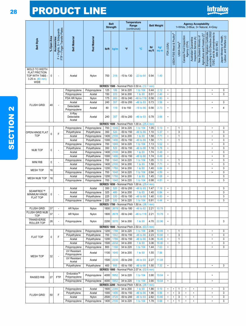
28 PRODUCT LINES
EC
TIO
N 2
MOLD TO WIDTH FLAT FRICTION
TOP WITH TABS - 3.25 in. (83 mm)
WIDE
0 - Acetal Nylon 700 318 -10 to 130 -23 to 64 0.94 1.40
SERIES 1500 - Nominal Pitch 0.50 in. (12.7 mm)
FLUSH GRID 48 -
Polypropylene Polypropylene 125 186 34 to 220 1 to 104 0.44 2.12 • • 3Polypropylene Acetal 150 223 34 to 200 1 to 93 0.51 2.40 • • 3FDA HR Nylon Nylon 175 260 -50 to 240 -46 to 116 0.58 2.83 •
Acetal Acetal 240 357 -50 to 200 -46 to 93 0.73 3.56 • • 3Detectable
Polypropylene Acetal 80 119 0 to 150 -18 to 66 0.56 2.73 • • 4
X-Ray Detectable
AcetalAcetal 240 357 -50 to 200 -46 to 93 0.78 3.66 •
SERIES 1600 - Nominal Pitch 1.00 in. (25.4 mm)
OPEN HINGE FLAT TOP 0 F
Polypropylene Polypropylene 700 1040 34 to 220 1 to 104 1.05 5.13 • 1 • 3Polyethylene Polyethylene 350 520 -50 to 150 -46 to 66 1.10 5.37 • 3 • 3
Acetal Polypropylene 1400 2100 34 to 200 1 to 93 1.58 7.71 • 1 • 3Acetal Polyethylene 1000 1490 -50 to 150 -46 to 66 1.58 7.71 • 1 • 3
NUB TOP 0 -
Polypropylene Polypropylene 700 1040 34 to 220 1 to 104 1.13 5.52 • • 3Polyethylene Polyethylene 350 520 -50 to 150 -46 to 66 1.18 5.76 • • 3
Acetal Polypropylene 1400 2100 34 to 200 1 to 93 1.74 8.49 • • 3Acetal Polyethylene 1000 1490 -50 to 150 -46 to 66 1.74 8.49 • • 3
MINI RIB 0 -Polypropylene Polypropylene 700 1040 34 to 220 1 to 104 1.05 5.13 • 1 • 3
Acetal Polypropylene 1400 2100 34 to 200 1 to 93 1.58 7.71 • 1 • 3
MESH TOP 16Acetal Polypropylene 1200 1780 34 to 200 1 to 93 1.40 6.84 • • 3
Polypropylene Polypropylene 700 1040 34 to 220 1 to 104 0.94 4.59 • • 3
MESH NUB TOP 16Acetal Polypropylene 1200 1780 34 to 200 1 to 93 1.45 7.08 • 3
Polypropylene Polypropylene 700 1040 34 to 220 1 to 104 0.98 4.81 • 3SERIES 1650 - Nominal Pitch 1.00 in. (25.4 mm)
SEAMFREE™ MINIMUM HINGE
FLAT TOP0 -
Acetal Acetal 350 520 -50 to 200 -46 to 93 1.47 7.18 • 3Acetal Polypropylene 325 480 34 to 200 1 to 93 1.40 6.84 • 3Acetal Polyethylene 225 330 -50 to 150 -46 to 66 1.40 6.83 • 3
Polypropylene Polypropylene 225 330 34 to 220 1 to 104 0.91 4.44 • 3SERIES 1700 - Nominal Pitch 1.50 in. (38.1 mm)
FLUSH GRID 37 - AR Nylon Nylon 1800 2678 -50 to 180 -46 to 82 2.21 10.78FLUSH GRID NUB
TOP 37 - AR Nylon Nylon 1800 2678 -50 to 240 -46 to 116 2.21 10.78 •
TRANSVERSE ROLLER TOP 26 - Polypropylene Nylon 2200 3270 34 to 200 1 to 93 4.70 22.96 • 3
SERIES 1800 - Nominal Pitch 2.50 in. (63.5 mm)
FLAT TOP 0 F
Polypropylene Polypropylene 1200 1786 34 to 220 1 to 104 2.06 10.06 • 1 • 3Polyethylene Polyethylene 700 1042 -50 to 150 -46 to 66 2.23 10.90 • 3 • 3
Acetal Polyethylene 1200 1786 -50 to 150 -46 to 66 3.36 16.40 • 1 • 3Acetal Polypropylene 1500 2232 34 to 200 1 to 93 3.36 16.40 • 1 • 3
MESH TOP 32 -
Polypropylene Polypropylene 800 1190 34 to 220 1 to 104 1.44 7.03 • • 3UV Resistant Polypropylene Acetal 1100 1640 34 to 200 1 to 93 1.55 7.56
UV Resistant Acetal Acetal 1500 2230 -50 to 200 -46 to 93 2.27 11.08
Polyethylene Polyethylene 400 595 -50 to 150 -46 to 66 1.50 7.32 • • 3SERIES 1900 - Nominal Pitch 2.07 in. (52.6 mm)
RAISED RIB 27 FTPEnduralox™
Polypropylene Polypropylene 4000 5952 34 to 220 1 to 104 3.90 19.04 • •
Polypropylene Polypropylene 4000 5952 34 to 220 1 to 104 3.90 19.04 • •SERIES 2200 - Nominal Pitch 1.50 in. (38.1 mm)
FLUSH GRID 50 F
Polypropylene Acetal 1600 2380 34 to 200 1 to 93 1.86 9.10 • • 1 • • • 3Polyethylene Acetal 1000 1490 -50 to 150 -46 to 66 1.96 9.56 • • 3 • • • 3
Acetal Nylon 2500 3720 -50 to 200 -46 to 93 2.82 13.80 • • 3 • • • 3Polypropylene Polypropylene 1400 2100 34 to 220 1 to 104 1.78 8.69 • • 1 • • • 3
Belt
Styl
e
% O
pen
Area
Acce
ssor
ies:
F =
Flig
hts,
S =
Sid
egua
rds
FTP
= Fi
nger
Tra
nsfe
r Pla
tes
Belt
Mat
eria
l
Rod
Mat
eria
l
BeltStrength
TemperatureRange
(continuous)Belt Weight Agency Acceptability
1=White, 2=Blue, 3= Natural, 4=Grey
lb/ft kg/m °F °C lb/sq ft
kg/sq m
FDA
(USA
)
USDA
-FSI
S M
eat &
Pou
ltrya
USDA
Dai
ryb
Cana
da F
ood
Insp
ectio
n Ag
ency
(CFA
)Au
stra
lian
Qua
rant
ine
Insp
ectio
n Se
rvice
(A)
New
Zeal
and
Min
istry
of
Agric
ultu
re a
nd F
ores
try (Z
)c
Euro
pean
Mig
ratio
n Ce
rtific
ate
acco
rdin
g to
EU
Dire
ctive
200
2/72
/EC
and
its a
men
dmen
ts to
da
te (E
U M
C)
Japa
n M
inist
ry o
f Hea
lth,
Labo
ur, a
nd W
elfa
re (J
)
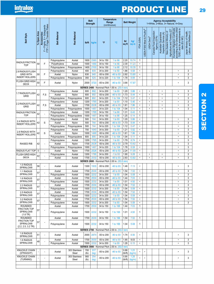
PRODUCT LINE 29
SE
CT
ION
2
RADIUS FRICTION TOP 50 F
Polypropylene Acetal 1600 2380 34 to 150 1 to 66 2.20 10.74 1Polyethylene Acetal 1000 1490 34 to 150 1 to 66 2.30 11.23 •
Polypropylene Polypropylene 1400 2100 34 to 150 1 to 66 2.12 10.35 1
2.6 RADIUS FLUSH GRID WITH
INSERT ROLLERS50 F
Polypropylene Acetal 400 600 34 to 200 1 to 93 1.86 9.08 • • 3Acetal Nylon 630 940 -50 to 200 -46 to 93 2.82 13.80 • • 3
Polypropylene Polypropylene 350 520 34 to 220 1 to 104 1.78 8.69 • • 3FLUSH GRID HIGH
DECK 50 F Acetal Nylon 2500 3720 -50 to 200 -46 to 93 3.66 17.87 • 3
SERIES 2400 - Nominal Pitch 1.00 in. (25.4 mm)
1.7 RADIUS FLUSH GRID 42 F,S
Polypropylene Acetal 600 892 34 to 200 1 to 93 1.20 5.86 • • • • 3Acetal Nylon 600 892 -50 to 200 -46 to 93 1.73 8.44 • • • • 3
Polypropylene Polypropylene 600 892 34 to 220 1 to 104 1.12 5.47 • • • • 3
2.2 RADIUS FLUSH GRID 42 F,S
Polypropylene Acetal 1200 1785 34 to 200 1 to 93 1.10 5.40 • • • • 3Acetal Nylon 1700 2528 -50 to 200 -46 to 93 1.61 7.86 • • • • 3
Polypropylene Polypropylene 1000 1487 34 to 220 1 to 104 1.04 5.11 • • • • 3RADIUS FRICTION
TOP 42 -Polypropylene Acetal 1200 1785 34 to 150 1 to 66 1.31 6.43 1Polypropylene Polypropylene 1000 1487 34 to 150 1 to 66 1.25 6.14 1
2.4 RADIUS WITH INSERT ROLLERS 42 S
Polypropylene Acetal 500 744 34 to 200 1 to 93 1.20 5.86 • • 3Acetal Nylon 500 744 -50 to 200 -46 to 93 1.73 8.44 • • 3
Polypropylene Polypropylene 500 744 34 to 220 1 to 104 1.12 5.47 • • 3
2.8 RADIUS WITH INSERT ROLLERS 42 S
Polypropylene Acetal 700 1040 34 to 200 1 to 93 1.21 5.92 • • 3Acetal Nylon 1000 1490 -50 to 200 -46 to 93 1.61 7.86 • • 3
Polypropylene Polypropylene 600 890 34 to 220 1 to 104 1.04 5.11 • • 3
RAISED RIB 42 -Polypropylene Acetal 1200 1785 34 to 200 1 to 93 1.79 8.74 • • 3
Acetal Nylon 1700 2528 -50 to 200 -46 to 93 2.79 13.62 • • 3Polypropylene Polypropylene 1000 1487 34 to 220 1 to 104 1.76 8.59 • • 3
RADIUS FLAT TOP 0 - Acetal Nylon 1700 2528 -50 to 200 -46 to 93 2.24 11.00 • • 3FLUSH GRID HIGH
DECK 42 -Polypropylene Acetal 1200 1785 34 to 200 -1 to 93 1.90 9.28 • • • • 3
Acetal Acetal 1700 2530 -50 to 200 -46 to 93 2.83 13.82 • • • • 3SERIES 2600 - Nominal Pitch 2.00 in. (50.8 mm)
1.0 RADIUS SPIRALOX® 56 - Acetal Acetal 1300 1935 -50 to 200 -46 to 93 1.46 7.13 • • 3
1.1 RADIUS SPIRALOX® 57 -
Acetal Acetal 1700 2530 -50 to 200 -46 to 93 1.54 7.52 • • 3Polypropylene Acetal 1500 2232 34 to 200 1 to 93 1.04 5.08 • • 3
1.6 RADIUS SPIRALOX® 57 -
Acetal Acetal 1700 2530 -50 to 200 -46 to 93 1.44 7.03 • • 3Polypropylene Acetal 1500 2232 34 to 200 1 to 93 1.01 4.93 • • 3
2.2 RADIUS SPIRALOX® 57 -
Acetal Acetal 1700 2530 -50 to 200 -46 to 93 1.54 7.52 • • 3Polypropylene Acetal 1500 2232 34 to 200 1 to 93 1.04 5.08 • • 3
2.5 RADIUS SPIRALOX® 57 -
Acetal Acetal 1700 2530 -50 to 200 -46 to 93 1.54 7.52 • • 3Polypropylene Acetal 1500 2232 34 to 200 1 to 93 1.04 5.08 • • 3
3.2 RADIUS SPIRALOX® 57 -
Acetal Acetal 1700 2530 -50 to 200 -46 to 93 1.54 7.52 • • 3Polypropylene Acetal 1500 2232 34 to 200 1 to 93 1.04 5.08 • • 3
ROUNDED FRICTION TOP
SPIRALOX®(1.6 TR)
57 -
Acetal Acetal 1700 2530 34 to 150 1 to 166 1.44 7.03 1
Polypropylene Acetal 1500 2232 34 to 150 1 to 166 1.01 4.93 1
ROUNDED FRICTION TOP
SPIRALOX®(2.2, 2.5, 3.2 TR)
57 -
Acetal Acetal 1700 2530 34 to 150 1 to 166 1.54 7.52 1
Polypropylene Acetal 1500 2232 34 to 150 1 to 166 1.04 5.08 1
SERIES 2700 - Nominal Pitch 2.00 in. (50.8 mm)1.6 RADIUS SPIRALOX® 51 - Acetal Acetal 2000 2974 -50 to 200 -46 to 93 1.74 8.50 • • 3
1.6 RADIUS SPIRALOX® 48 -
Acetal Acetal 1700 2530 -50 to 200 -46 to 93 1.85 9.03 • • 3Polypropylene Acetal 1500 2232 34 to 200 1 to 93 1.26 6.15 • • 3
SERIES 3000 - Nominal Pitch 2.00 in. (50.8 mm)KNUCKLE CHAIN
(STRAIGHT) - - Acetal 303 Stainless Steel
700(lb)
317 (kg) -50 to 200 -46 to 93 0.88
(lb/ft)1.21
(kg/m) • • • 3
KNUCKLE CHAIN (TURNING) - - Acetal 303 Stainless
Steel560(lb)
254 (kg) -50 to 200 -46 to 93 0.90
(lb/ft)1.25
(kg/m) • • • 3
Belt
Styl
e
% O
pen
Area
Acce
ssor
ies:
F =
Flig
hts,
S =
Sid
egua
rds
FTP
= Fi
nger
Tra
nsfe
r Pla
tes
Belt
Mat
eria
l
Rod
Mat
eria
l
BeltStrength
TemperatureRange
(continuous)Belt Weight Agency Acceptability
1=White, 2=Blue, 3= Natural, 4=Grey
lb/ft kg/m °F °C lb/sq ft
kg/sq m
FDA
(USA
)
USDA
-FSI
S M
eat &
Pou
ltrya
USDA
Dai
ryb
Cana
da F
ood
Insp
ectio
n Ag
ency
(CFA
)Au
stra
lian
Qua
rant
ine
Insp
ectio
n Se
rvice
(A)
New
Zeal
and
Min
istry
of
Agric
ultu
re a
nd F
ores
try (Z
)c
Euro
pean
Mig
ratio
n Ce
rtific
ate
acco
rdin
g to
EU
Dire
ctive
200
2/72
/EC
and
its a
men
dmen
ts to
da
te (E
U M
C)
Japa
n M
inist
ry o
f Hea
lth,
Labo
ur, a
nd W
elfa
re (J
)
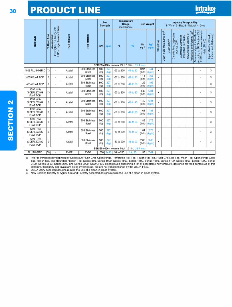
30 PRODUCT LINES
EC
TIO
N 2
SERIES 4000 - Nominal Pitch 1.00 in. (25.4 mm)
4009 FLUSH GRID 13 - Acetal 303 Stainless Steel
500(lb)
227 (kg) -50 to 200 -46 to 93 0.97
(lb/ft)1.44
(kg/m) • • 3
4009 FLAT TOP 0 - Acetal 303 Stainless Steel
500(lb)
227 (kg) -50 to 200 -46 to 93 1.11
(lb/ft)1.65
(kg/m) • • 3
4014 FLAT TOP 0 - Acetal 303 Stainless Steel
500(lb)
227 (kg) -50 to 200 -46 to 93 1.29
(lb/ft)1.92
(kg/m) • • 3
4090 (4.5) SIDEFLEXING
FLAT TOP 13 - Acetal 303 Stainless
Steel500(lb)
227 (kg) -50 to 200 -46 to 93 1.40
(lb/ft)6.84
(kg/m) • • 3
4091 (4.5) SIDEFLEXING
FLAT TOP0 - Acetal 303 Stainless
Steel500(lb)
227 (kg) -50 to 200 -46 to 93 1.40
(lb/ft)6.84
(kg/m) • • 3
4092 (4.5) SIDEFLEXING
FLAT TOP0 - Acetal 303 Stainless
Steel500(lb)
227 (kg) -50 to 200 -46 to 93 1.61
(lb/ft)7.86
(kg/m) • • 3
4090 (7.5) SIDEFLEXING
FLAT TOP0 - Acetal 303 Stainless
Steel500(lb)
227 (kg) -50 to 200 -46 to 93 1.86
(lb/ft)2.76
(kg/m) • • 3
4091 (7.5) SIDEFLEXING
FLAT TOP0 - Acetal 303 Stainless
Steel500(lb)
227 (kg) -50 to 200 -46 to 93 1.84
(lb/ft)2.73
(kg/m) • • 3
4092 (7.5) SIDEFLEXING
FLAT TOP0 - Acetal 303 Stainless
Steel500(lb)
227 (kg) -50 to 200 -46 to 93 2.05
(lb/ft)3.05
(kg/m) • • 3
SERIES 9000 - Nominal Pitch 1.01 in. (25.7 mm)FLUSH GRID 58 - PVDF PVDF 1000 1490 34 to 200 1 to 93 1.57 7.64
a. Prior to Intralox’s development of Series 800 Flush Grid, Open Hinge, Perforated Flat Top, Tough Flat Top, Flush Grid Nub Top, Mesh Top, Open Hinge ConeTop, Roller Top, and Rounded Friction Top, Series 850, Series 1000, Series 1500, Series 1600, Series 1650, Series 1700, Series 1800, Series 1900, Series2400, Series 2600, Series 2700 and Series 9000, USDA-FSIS discontinued publishing a list of acceptable new products designed for food contact.As of thisliterature, third party approvals are being investigated, but are not yet sanctioned by the USDA-FSIS.
b. USDA Dairy accepted designs require the use of a clean-in-place system.c. New Zealand Ministry of Agriculture and Forestry accepted designs require the use of a clean-in-place system.
Belt
Styl
e
% O
pen
Area
Acce
ssor
ies:
F =
Flig
hts,
S =
Sid
egua
rds
FTP
= Fi
nger
Tra
nsfe
r Pla
tes
Belt
Mat
eria
l
Rod
Mat
eria
l
BeltStrength
TemperatureRange
(continuous)Belt Weight Agency Acceptability
1=White, 2=Blue, 3= Natural, 4=Grey
lb/ft kg/m °F °C lb/sq ft
kg/sq m
FDA
(USA
)
USDA
-FSI
S M
eat &
Pou
ltrya
USDA
Dai
ryb
Cana
da F
ood
Insp
ectio
n Ag
ency
(CFA
)Au
stra
lian
Qua
rant
ine
Insp
ectio
n Se
rvice
(A)
New
Zeal
and
Min
istry
of
Agric
ultu
re a
nd F
ores
try (Z
)c
Euro
pean
Mig
ratio
n Ce
rtific
ate
acco
rdin
g to
EU
Dire
ctive
200
2/72
/EC
and
its a
men
dmen
ts to
da
te (E
U M
C)
Japa
n M
inist
ry o
f Hea
lth,
Labo
ur, a
nd W
elfa
re (J
)
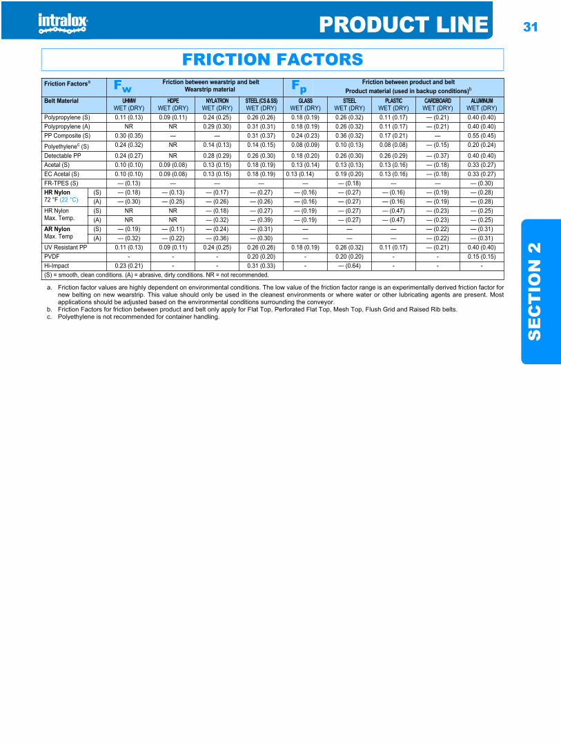
PRODUCT LINE 31
SE
CT
ION
2
FRICTION FACTORSFriction Factorsa Fw
Friction between wearstrip and beltWearstrip material Fp
Friction between product and beltProduct material (used in backup conditions)b
Belt Material UHMWWET (DRY)
HDPEWET (DRY)
NYLATRONWET (DRY)
STEEL (CS&SS)WET (DRY)
GLASSWET (DRY)
STEELWET (DRY)
PLASTICWET (DRY)
CARDBOARDWET (DRY)
ALUMINUMWET (DRY)
Polypropylene (S) 0.11 (0.13) 0.09 (0.11) 0.24 (0.25) 0.26 (0.26) 0.18 (0.19) 0.26 (0.32) 0.11 (0.17) — (0.21) 0.40 (0.40)Polypropylene (A) NR NR 0.29 (0.30) 0.31 (0.31) 0.18 (0.19) 0.26 (0.32) 0.11 (0.17) — (0.21) 0.40 (0.40)PP Composite (S) 0.30 (0.35) — — 0.31 (0.37) 0.24 (0.23) 0.36 (0.32) 0.17 (0.21) — 0.55 (0.45)
Polyethylenec (S) 0.24 (0.32) NR 0.14 (0.13) 0.14 (0.15) 0.08 (0.09) 0.10 (0.13) 0.08 (0.08) — (0.15) 0.20 (0.24)
Detectable PP 0.24 (0.27) NR 0.28 (0.29) 0.26 (0.30) 0.18 (0.20) 0.26 (0.30) 0.26 (0.29) — (0.37) 0.40 (0.40)Acetal (S) 0.10 (0.10) 0.09 (0.08) 0.13 (0.15) 0.18 (0.19) 0.13 (0.14) 0.13 (0.13) 0.13 (0.16) — (0.18) 0.33 (0.27)EC Acetal (S) 0.10 (0.10) 0.09 (0.08) 0.13 (0.15) 0.18 (0.19) 0.13 (0.14) 0.19 (0.20) 0.13 (0.16) — (0.18) 0.33 (0.27)FR-TPES (S) — (0.13) — — — — — (0.18) — — — (0.30)HR Nylon72 °F (22 °C)
(S) — (0.18) — (0.13) — (0.17) — (0.27) — (0.16) — (0.27) — (0.16) — (0.19) — (0.28)(A) — (0.30) — (0.25) — (0.26) — (0.26) — (0.16) — (0.27) — (0.16) — (0.19) — (0.28)
HR NylonMax. Temp.
(S) NR NR — (0.18) — (0.27) — (0.19) — (0.27) — (0.47) — (0.23) — (0.25)(A) NR NR — (0.32) — (0.39) — (0.19) — (0.27) — (0.47) — (0.23) — (0.25)
AR NylonMax. Temp
(S) — (0.19) — (0.11) — (0.24) — (0.31) — — — — (0.22) — (0.31)(A) — (0.32) — (0.22) — (0.36) — (0.30) — — — — (0.22) — (0.31)
UV Resistant PP 0.11 (0.13) 0.09 (0.11) 0.24 (0.25) 0.26 (0.26) 0.18 (0.19) 0.26 (0.32) 0.11 (0.17) — (0.21) 0.40 (0.40)PVDF - - - 0.20 (0.20) - 0.20 (0.20) - - 0.15 (0.15)Hi-Impact 0.23 (0.21) - - 0.31 (0.33) - — (0.64) - - -(S) = smooth, clean conditions. (A) = abrasive, dirty conditions. NR = not recommended.
a. Friction factor values are highly dependent on environmental conditions. The low value of the friction factor range is an experimentally derived friction factor fornew belting on new wearstrip. This value should only be used in the cleanest environments or where water or other lubricating agents are present. Mostapplications should be adjusted based on the environmental conditions surrounding the conveyor.
b. Friction Factors for friction between product and belt only apply for Flat Top, Perforated Flat Top, Mesh Top, Flush Grid and Raised Rib belts.c. Polyethylene is not recommended for container handling.
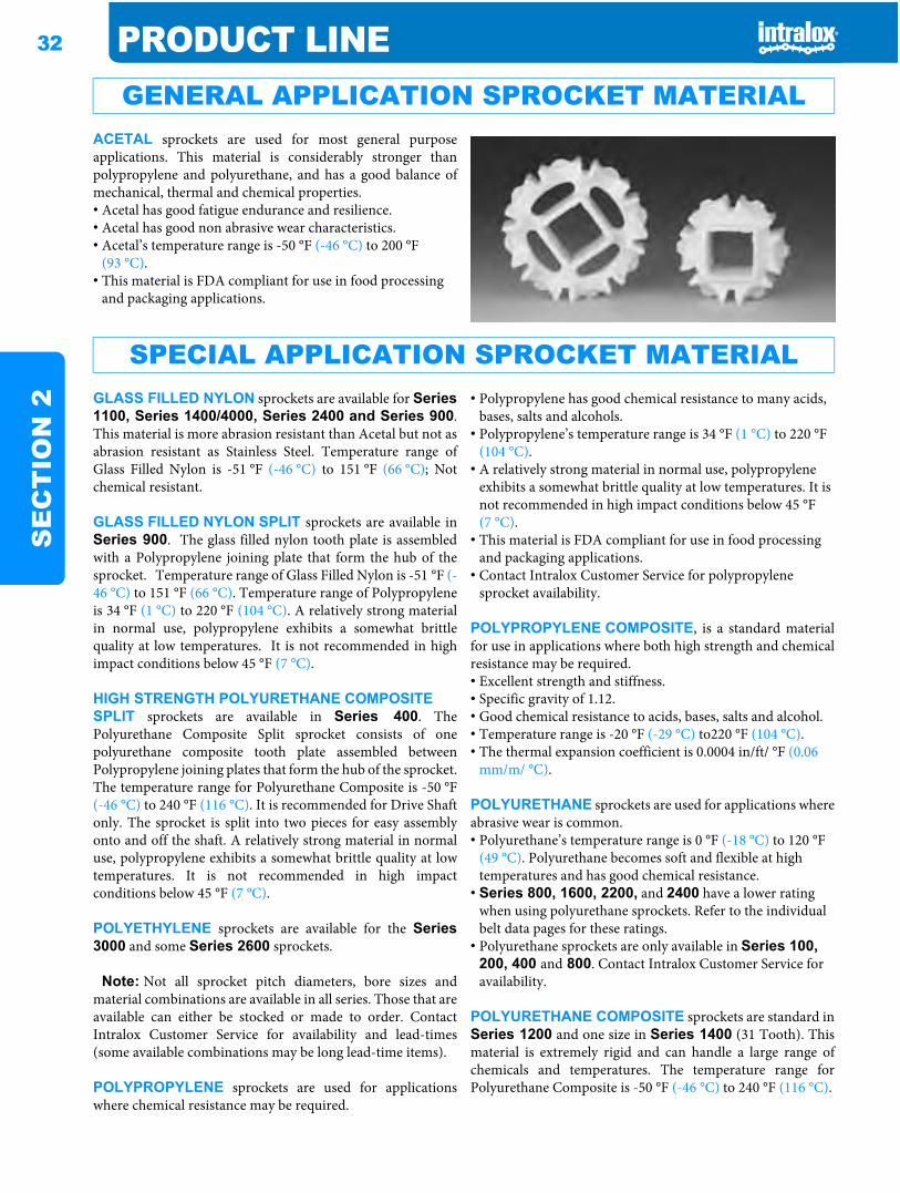
32 PRODUCT LINES
EC
TIO
N 2
ACETAL sprockets are used for most general purposeapplications. This material is considerably stronger thanpolypropylene and polyurethane, and has a good balance ofmechanical, thermal and chemical properties.• Acetal has good fatigue endurance and resilience.• Acetal has good non abrasive wear characteristics.• Acetal’s temperature range is -50 °F (-46 °C) to 200 °F
(93 °C).• This material is FDA compliant for use in food processing
and packaging applications.
GLASS FILLED NYLON sprockets are available for Series1100, Series 1400/4000, Series 2400 and Series 900.This material is more abrasion resistant than Acetal but not asabrasion resistant as Stainless Steel. Temperature range ofGlass Filled Nylon is -51 °F (-46 °C) to 151 °F (66 °C); Notchemical resistant.
GLASS FILLED NYLON SPLIT sprockets are available inSeries 900. The glass filled nylon tooth plate is assembledwith a Polypropylene joining plate that form the hub of thesprocket. Temperature range of Glass Filled Nylon is -51 °F (-46 °C) to 151 °F (66 °C). Temperature range of Polypropyleneis 34 °F (1 °C) to 220 °F (104 °C). A relatively strong materialin normal use, polypropylene exhibits a somewhat brittlequality at low temperatures. It is not recommended in highimpact conditions below 45 °F (7 °C).
HIGH STRENGTH POLYURETHANE COMPOSITE SPLIT sprockets are available in Series 400. ThePolyurethane Composite Split sprocket consists of onepolyurethane composite tooth plate assembled betweenPolypropylene joining plates that form the hub of the sprocket.The temperature range for Polyurethane Composite is -50 °F(-46 °C) to 240 °F (116 °C). It is recommended for Drive Shaftonly. The sprocket is split into two pieces for easy assemblyonto and off the shaft. A relatively strong material in normaluse, polypropylene exhibits a somewhat brittle quality at lowtemperatures. It is not recommended in high impactconditions below 45 °F (7 °C).
POLYETHYLENE sprockets are available for the Series3000 and some Series 2600 sprockets.
Note: Not all sprocket pitch diameters, bore sizes andmaterial combinations are available in all series. Those that areavailable can either be stocked or made to order. ContactIntralox Customer Service for availability and lead-times(some available combinations may be long lead-time items).
POLYPROPYLENE sprockets are used for applicationswhere chemical resistance may be required.
• Polypropylene has good chemical resistance to many acids, bases, salts and alcohols.
• Polypropylene’s temperature range is 34 °F (1 °C) to 220 °F (104 °C).
• A relatively strong material in normal use, polypropylene exhibits a somewhat brittle quality at low temperatures. It is not recommended in high impact conditions below 45 °F (7 °C).
• This material is FDA compliant for use in food processing and packaging applications.
• Contact Intralox Customer Service for polypropylene sprocket availability.
POLYPROPYLENE COMPOSITE, is a standard materialfor use in applications where both high strength and chemicalresistance may be required.• Excellent strength and stiffness.• Specific gravity of 1.12.• Good chemical resistance to acids, bases, salts and alcohol.• Temperature range is -20 °F (-29 °C) to220 °F (104 °C).• The thermal expansion coefficient is 0.0004 in/ft/ °F (0.06
mm/m/ °C).
POLYURETHANE sprockets are used for applications whereabrasive wear is common.• Polyurethane’s temperature range is 0 °F (-18 °C) to 120 °F
(49 °C). Polyurethane becomes soft and flexible at high temperatures and has good chemical resistance.
• Series 800, 1600, 2200, and 2400 have a lower rating when using polyurethane sprockets. Refer to the individual belt data pages for these ratings.
• Polyurethane sprockets are only available in Series 100, 200, 400 and 800. Contact Intralox Customer Service for availability.
POLYURETHANE COMPOSITE sprockets are standard inSeries 1200 and one size in Series 1400 (31 Tooth). Thismaterial is extremely rigid and can handle a large range ofchemicals and temperatures. The temperature range forPolyurethane Composite is -50 °F (-46 °C) to 240 °F (116 °C).
GENERAL APPLICATION SPROCKET MATERIAL
SPECIAL APPLICATION SPROCKET MATERIAL
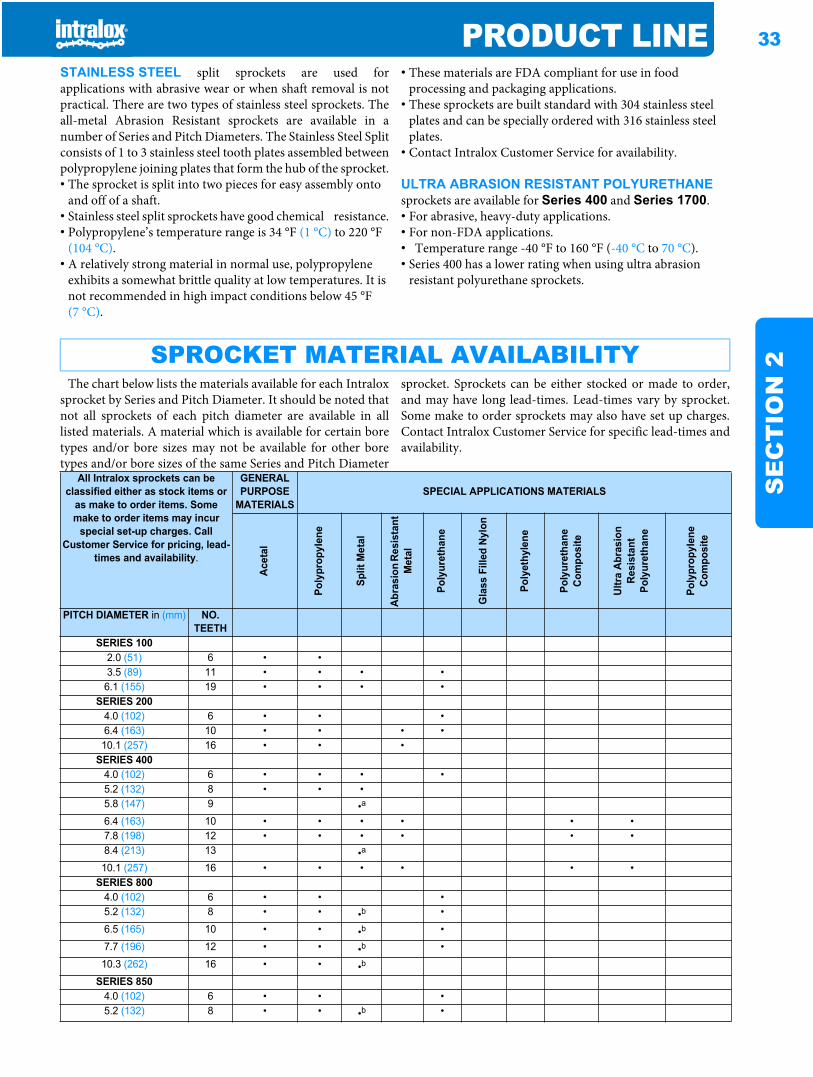
PRODUCT LINE 33
SE
CT
ION
2
STAINLESS STEEL split sprockets are used forapplications with abrasive wear or when shaft removal is notpractical. There are two types of stainless steel sprockets. Theall-metal Abrasion Resistant sprockets are available in anumber of Series and Pitch Diameters. The Stainless Steel Splitconsists of 1 to 3 stainless steel tooth plates assembled betweenpolypropylene joining plates that form the hub of the sprocket.• The sprocket is split into two pieces for easy assembly onto
and off of a shaft.• Stainless steel split sprockets have good chemical resistance.• Polypropylene’s temperature range is 34 °F (1 °C) to 220 °F
(104 °C).• A relatively strong material in normal use, polypropylene
exhibits a somewhat brittle quality at low temperatures. It is not recommended in high impact conditions below 45 °F (7 °C).
• These materials are FDA compliant for use in food processing and packaging applications.
• These sprockets are built standard with 304 stainless steel plates and can be specially ordered with 316 stainless steel plates.
• Contact Intralox Customer Service for availability.
ULTRA ABRASION RESISTANT POLYURETHANEsprockets are available for Series 400 and Series 1700.• For abrasive, heavy-duty applications.• For non-FDA applications.• Temperature range -40 °F to 160 °F (-40 °C to 70 °C).• Series 400 has a lower rating when using ultra abrasion
resistant polyurethane sprockets.
The chart below lists the materials available for each Intraloxsprocket by Series and Pitch Diameter. It should be noted thatnot all sprockets of each pitch diameter are available in alllisted materials. A material which is available for certain boretypes and/or bore sizes may not be available for other boretypes and/or bore sizes of the same Series and Pitch Diameter
sprocket. Sprockets can be either stocked or made to order,and may have long lead-times. Lead-times vary by sprocket.Some make to order sprockets may also have set up charges.Contact Intralox Customer Service for specific lead-times andavailability.
SPROCKET MATERIAL AVAILABILITY
All Intralox sprockets can be classified either as stock items or
as make to order items. Some make to order items may incur
special set-up charges. Call Customer Service for pricing, lead-
times and availability.
GENERAL PURPOSE
MATERIALSSPECIAL APPLICATIONS MATERIALS
Acet
al
Poly
prop
ylen
e
Split
Met
al
Abra
sion
Res
ista
nt
Met
al
Poly
uret
hane
Gla
ss F
illed
Nyl
on
Poly
ethy
lene
Poly
uret
hane
Co
mpo
site
Ultra
Abr
asio
n Re
sist
ant
Poly
uret
hane
Poly
prop
ylen
e Co
mpo
site
PITCH DIAMETER in (mm) NO.TEETH
SERIES 1002.0 (51) 6 • •3.5 (89) 11 • • • •6.1 (155) 19 • • • •
SERIES 2004.0 (102) 6 • • •6.4 (163) 10 • • • •10.1 (257) 16 • • •
SERIES 4004.0 (102) 6 • • • •5.2 (132) 8 • • •5.8 (147) 9 •a
6.4 (163) 10 • • • • • •7.8 (198) 12 • • • • • •8.4 (213) 13 •a
10.1 (257) 16 • • • • • •SERIES 800
4.0 (102) 6 • • •5.2 (132) 8 • • •b •6.5 (165) 10 • • •b •7.7 (196) 12 • • •b •10.3 (262) 16 • • •b
SERIES 8504.0 (102) 6 • • •5.2 (132) 8 • • •b •
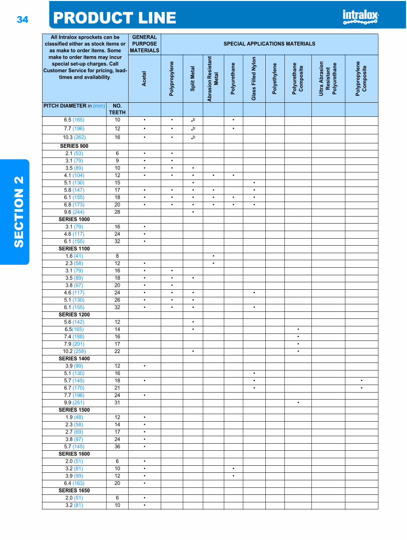
34 PRODUCT LINES
EC
TIO
N 2
6.5 (165) 10 • • •b •7.7 (196) 12 • • •b •10.3 (262) 16 • • •b
SERIES 9002.1 (53) 6 • •3.1 (79) 9 • •3.5 (89) 10 • • •4.1 (104) 12 • • • • •5.1 (130) 15 • •5.8 (147) 17 • • • • •6.1 (155) 18 • • • • • •6.8 (173) 20 • • • • • •9.6 (244) 28 •
SERIES 10003.1 (79) 16 •4.6 (117) 24 •6.1 (155) 32 •
SERIES 11001.6 (41) 8 •2.3 (58) 12 • •3.1 (79) 16 • •3.5 (89) 18 • • •3.8 (97) 20 • •4.6 (117) 24 • • • •5.1 (130) 26 • • •6.1 (155) 32 • • • •
SERIES 12005.6 (142) 12 •6.5(165) 14 • •7.4 (188) 16 •7.9 (201) 17 •10.2 (258) 22 • •
SERIES 14003.9 (99) 12 •5.1 (130) 16 •5.7 (145) 18 • • •6.7 (170) 21 • •7.7 (196) 24 •9.9 (251) 31 •
SERIES 15001.9 (48) 12 •2.3 (58) 14 •2.7 (69) 17 •3.8 (97) 24 •5.7 (145) 36 •
SERIES 16002.0 (51) 6 •3.2 (81) 10 • •3.9 (99) 12 • •6.4 (163) 20 •
SERIES 16502.0 (51) 6 •3.2 (81) 10 •
All Intralox sprockets can be classified either as stock items or
as make to order items. Some make to order items may incur
special set-up charges. Call Customer Service for pricing, lead-
times and availability.
GENERAL PURPOSE
MATERIALSSPECIAL APPLICATIONS MATERIALS
Acet
al
Poly
prop
ylen
e
Split
Met
al
Abra
sion
Res
ista
nt
Met
al
Poly
uret
hane
Gla
ss F
illed
Nyl
on
Poly
ethy
lene
Poly
uret
hane
Co
mpo
site
Ultra
Abr
asio
n Re
sist
ant
Poly
uret
hane
Poly
prop
ylen
e Co
mpo
site
PITCH DIAMETER in (mm) NO.TEETH
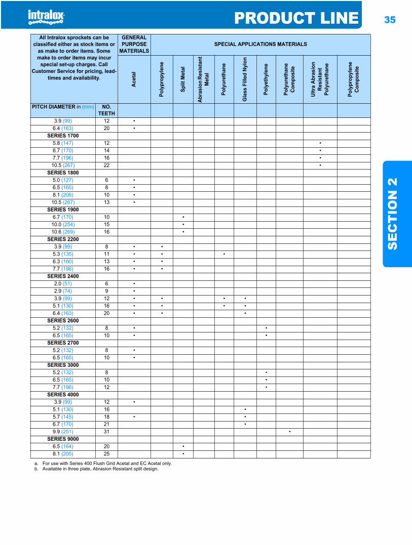
PRODUCT LINE 35
SE
CT
ION
2
3.9 (99) 12 •6.4 (163) 20 •
SERIES 17005.8 (147) 12 •6.7 (170) 14 •7.7 (196) 16 •10.5 (267) 22 •
SERIES 18005.0 (127) 6 •6.5 (165) 8 •8.1 (206) 10 •10.5 (267) 13 •
SERIES 19006.7 (170) 10 •10.0 (254) 15 •10.6 (269) 16 •
SERIES 22003.9 (99) 8 • •5.3 (135) 11 • • •6.3 (160) 13 • •7.7 (196) 16 • •
SERIES 24002.0 (51) 6 •2.9 (74) 9 •3.9 (99) 12 • • • •5.1 (130) 16 • • • •6.4 (163) 20 • • •
SERIES 26005.2 (132) 8 • •6.5 (165) 10 • •
SERIES 27005.2 (132) 8 •6.5 (165) 10 •
SERIES 30005.2 (132) 8 •6.5 (165) 10 •7.7 (196) 12 •
SERIES 40003.9 (99) 12 •5.1 (130) 16 •5.7 (145) 18 • •6.7 (170) 21 •9.9 (251) 31 •
SERIES 90006.5 (164) 20 •8.1 (205) 25 •
a. For use with Series 400 Flush Grid Acetal and EC Acetal only.b. Available in three plate, Abrasion Resistant split design.
All Intralox sprockets can be classified either as stock items or
as make to order items. Some make to order items may incur
special set-up charges. Call Customer Service for pricing, lead-
times and availability.
GENERAL PURPOSE
MATERIALSSPECIAL APPLICATIONS MATERIALS
Acet
al
Poly
prop
ylen
e
Split
Met
al
Abra
sion
Res
ista
nt
Met
al
Poly
uret
hane
Gla
ss F
illed
Nyl
on
Poly
ethy
lene
Poly
uret
hane
Co
mpo
site
Ultra
Abr
asio
n Re
sist
ant
Poly
uret
hane
Poly
prop
ylen
e Co
mpo
site
PITCH DIAMETER in (mm) NO.TEETH
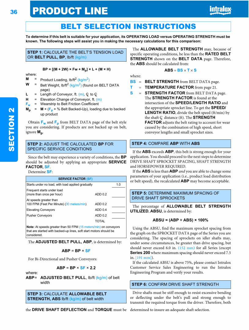
36 PRODUCT LINES
EC
TIO
N 2
Obtain Fw and Fp from BELT DATA page of the belt styleyou are considering. If products are not backed up on belt,ignore Mp.
Since the belt may experience a variety of conditions, the BPshould be adjusted by applying an appropriate SERVICEFACTOR, SF.
Determine SF:
The ADJUSTED BELT PULL, ABP, is determined by:
For Bi-Directional and Pusher Conveyors:
The ALLOWABLE BELT STRENGTH may, because ofspecific operating conditions, be less than the RATED BELTSTRENGTH shown on the BELT DATA page. Therefore,the ABS should be calculated from:
If the ABS exceeds ABP, this belt is strong enough for yourapplication. You should proceed to the next steps to determineDRIVE SHAFT SPROCKET SPACING, SHAFT STRENGTHand HORSEPOWER REQUIRED.
If the ABS is less than ABP and you are able to change someparameters of your application (i.e., product load distributionor belt speed), the recalculated ABP may become acceptable.
The percentage of ALLOWABLE BELT STRENGTHUTILIZED, ABSU, is determined by:
Using the ABSU, find the maximum sprocket spacing fromthe graph on the SPROCKET DATA page of the Series you areconsidering. The spacing of sprockets on idler shafts may,under some circumstances, be greater than drive spacing, butshould never exceed 6.0 in. (152 mm) for all Series (exceptSeries 200 where maximum spacing should never exceed 7.5in. [191 mm]).
If the calculated ABSU is above 75%, please contact IntraloxCustomer Service Sales Engineering to run the IntraloxEngineering Program and verify your results.
Drive shafts must be stiff enough to resist excessive bendingor deflecting under the belt’s pull and strong enough totransmit the required torque from the driver. Therefore, both
the DRIVE SHAFT DEFLECTION and TORQUE must be determined to insure an adequate shaft selection.
BELT SELECTION INSTRUCTIONSTo determine if this belt is suitable for your application, its OPERATING LOAD versus OPERATING STRENGTH must be known. The following steps will assist you in making the necessary calculations for this comparison:
STEP 1: CALCULATE THE BELT’S TENSION LOAD OR BELT PULL, BP, lb/ft (kg/m)
BP = [(M + 2W) × Fw + Mp] × L + (M × H)where:M = Product Loading, lb/ft2 (kg/m2)W = Belt Weight, lb/ft2 (kg/m2) (found on BELT DATA
page)L = Length of Conveyor, ft. (m), CL to CLH = Elevation Change of Conveyor, ft. (m)Fw = Wearstrip to Belt Friction CoefficientMp = M × (Fp × % Belt Backed-Up), loading due to backed
up product
STEP 2: ADJUST THE CALCULATED BP FOR SPECIFIC SERVICE CONDITIONS
SERVICE FACTOR (SF)
Starts under no load, with load applied gradually 1.0
Frequent starts under load(more than once per hour) ADD 0.2
At speeds greater than100 FPM (Feet Per Minute) (30 meters/min) ADD 0.2
Elevating Conveyors ADD 0.4
Pusher Conveyors ADD 0.2
TOTAL
Note: At speeds greater than 50 FPM (15 meters/min) on conveyors that are started with backed-up lines, soft start motors should be considered.
ABP = BP × SF
ABP = BP × SF × 2.2where:ABP= ADJUSTED BELT PULL, lb/ft (kg/m) of belt
width
STEP 3: CALCULATE ALLOWABLE BELT STRENGTH, ABS lb/ft (kg/m) of belt width
ABS = BS × T × Swhere:BS = BELT STRENGTH from BELT DATA page.T = TEMPERATURE FACTOR from page 21.S = STRENGTH FACTOR from BELT DATA page.
The STRENGTH FACTOR is found at the intersection of the SPEED/LENGTH RATIO and the appropriate sprocket line. To get the SPEED/LENGTH RATIO, divide the belt speed (ft/min) by the shaft CL distance (ft). The STRENGTHFACTOR adjusts the belt rating to account for wear caused by the combination of high speed, short conveyor lengths and small sprocket sizes.
STEP 4: COMPARE ABP WITH ABS
STEP 5: DETERMINE MAXIMUM SPACING OF DRIVE SHAFT SPROCKETS
ABSU = (ABP ÷ ABS) × 100%
STEP 6: CONFIRM DRIVE SHAFT STRENGTH
PRODUCT LINE 37
SE
CT
ION
2
Select a shaft size which fits your sprocket of choice from theSPROCKET DATA page.
Note: Most sprockets have more than one available boresize.
The shaft deflects under the combined loads of theADJUSTED BELT PULL and its own WEIGHT. TheTOTAL SHAFT LOAD, w, is found from:
For shafts supported by two bearings, the DEFLECTION, D,is calculated from:
If the calculated deflection is less than the recommendedmaximum of 0.10 in. (2.5 mm) for standard conveyors or 0.22in. (5.6 mm) for bi-directional units, calculate the requiredTORQUE. If not, use a larger size shaft, a stronger material ora shorter span between bearings, and recalculate thedeflection.
The TORQUE, To, to be transmitted is determined from:
Now compare To with the “Table 9 MAXIMUMRECOMMENDED TORQUE ON DRIVE SHAFT” (page 351),for shaft journal sizes shown. Using a journal diameter whichcan be machined on the shaft selected, determine its maximumrecommended torque. This value should exceed To. If not, trya stronger material or larger shaft.
DRIVE HORSEPOWER, HP, is found from:
POWER in WATTS is found from:
To obtain the required motor power you should addexpected power losses in the drive train between drive shaftand motor to the calculated POWER. See “Sectionthree: Design guidelines” (page 317), for recommendations.
Having determined the suitability of this belt, the sprocketspacing, the drive shaft size and the power requirements, youare now ready to select ACCESSORIES and to design theconveyor assembly.
w = (ABP + Q) × Bwhere:Q = SHAFT WEIGHT, lb/ft (kg/m), from SHAFT
DATA tableB = BELT WIDTH, ft. (m)
D = 5 ×w × LS³
384 E × Iwhere:Ls = LENGTH OF SHAFT between bearings, in.
(mm)E = MODULUS OF ELASTICITY from “Table 8
SHAFT DATA” (page 351).I = MOMENT OF INERTIA from “Table 8 SHAFT
DATA” (page 351).Note: For shafts supported by three bearings, see “DEFLECTIONS WITH INTERMEDIATE BEARINGS”(page 342).
To = ABP × B × PD2
where:PD = PITCH DIAMETER OF SPROCKET from the
SPROCKET DATA PAGE
STEP 7: DETERMINE THE POWER NEEDED TO DRIVE THE BELT
HP = ABP × B × V33000
where:ABP= ADJUSTED BELT PULL, lb/ft of belt widthB = BELT WIDTH, ft.V = BELT SPEED, ft/min
WATTS = ABP × B × V6.12
1 HP = 745.7 WATTSwhere:ABP= ADJUSTED BELT PULL, lb/ft of belt widthB = BELT WIDTH, ft.V = BELT SPEED, ft/min

38 PRODUCT LINES
EC
TIO
N 2
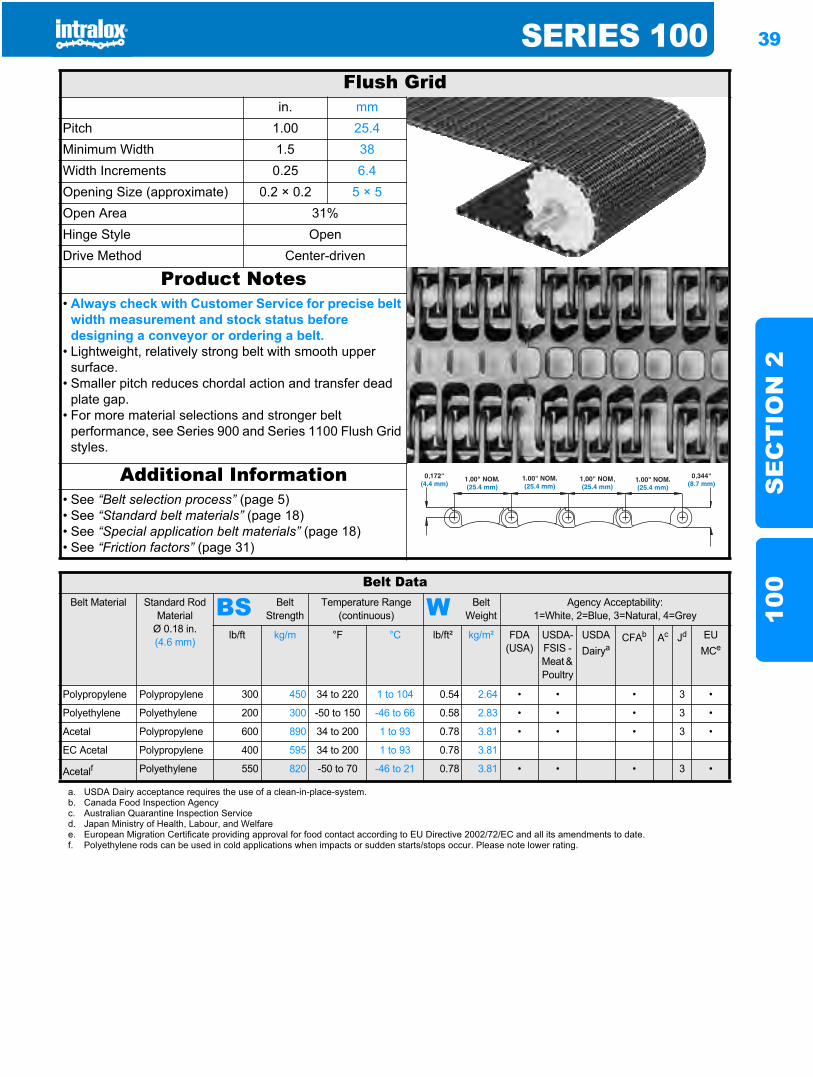
SERIES 100 39
SE
CT
ION
210
0
Straight running belts100
Flush Gridin. mm
Pitch 1.00 25.4Minimum Width 1.5 38Width Increments 0.25 6.4Opening Size (approximate) 0.2 × 0.2 5 × 5Open Area 31%Hinge Style OpenDrive Method Center-driven
Product Notes• Always check with Customer Service for precise belt
width measurement and stock status before designing a conveyor or ordering a belt.
• Lightweight, relatively strong belt with smooth upper surface.
• Smaller pitch reduces chordal action and transfer dead plate gap.
• For more material selections and stronger belt performance, see Series 900 and Series 1100 Flush Grid styles.
Additional Information• See “Belt selection process” (page 5)• See “Standard belt materials” (page 18)• See “Special application belt materials” (page 18)• See “Friction factors” (page 31)
Belt DataBelt Material Standard Rod
MaterialØ 0.18 in. (4.6 mm)
BS Belt Strength
Temperature Range (continuous) W Belt
WeightAgency Acceptability:
1=White, 2=Blue, 3=Natural, 4=Grey
lb/ft kg/m °F °C lb/ft² kg/m² FDA(USA)
USDA-FSIS - Meat & Poultry
USDADairya
CFAb Ac Jd EU MCe
Polypropylene Polypropylene 300 450 34 to 220 1 to 104 0.54 2.64 • • • 3 •
Polyethylene Polyethylene 200 300 -50 to 150 -46 to 66 0.58 2.83 • • • 3 •
Acetal Polypropylene 600 890 34 to 200 1 to 93 0.78 3.81 • • • 3 •
EC Acetal Polypropylene 400 595 34 to 200 1 to 93 0.78 3.81
Acetalf Polyethylene 550 820 -50 to 70 -46 to 21 0.78 3.81 • • • 3 •
a. USDA Dairy acceptance requires the use of a clean-in-place-system.b. Canada Food Inspection Agencyc. Australian Quarantine Inspection Serviced. Japan Ministry of Health, Labour, and Welfaree. European Migration Certificate providing approval for food contact according to EU Directive 2002/72/EC and all its amendments to date.f. Polyethylene rods can be used in cold applications when impacts or sudden starts/stops occur. Please note lower rating.
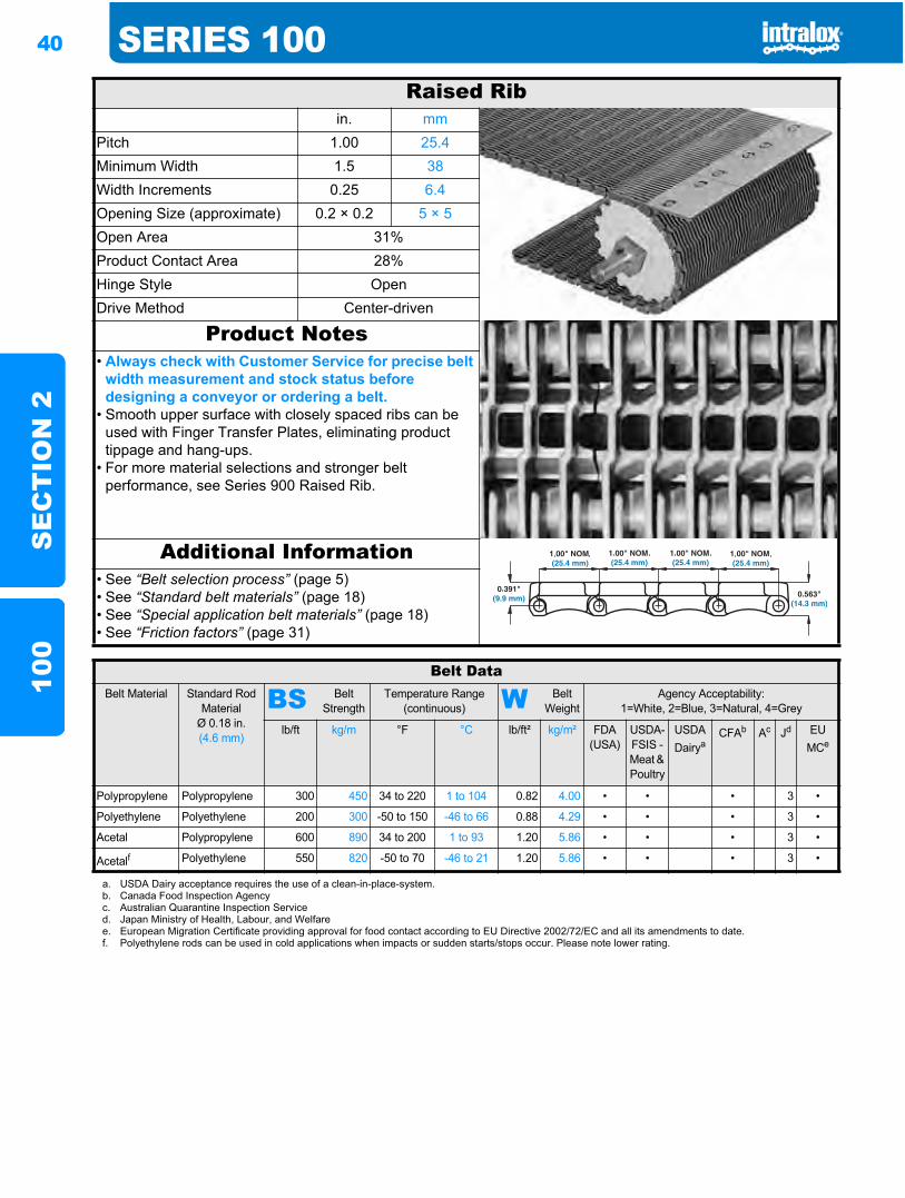
40 SERIES 100S
EC
TIO
N 2
100
Raised Ribin. mm
Pitch 1.00 25.4Minimum Width 1.5 38Width Increments 0.25 6.4Opening Size (approximate) 0.2 × 0.2 5 × 5Open Area 31%Product Contact Area 28%Hinge Style OpenDrive Method Center-driven
Product Notes• Always check with Customer Service for precise belt
width measurement and stock status before designing a conveyor or ordering a belt.
• Smooth upper surface with closely spaced ribs can be used with Finger Transfer Plates, eliminating product tippage and hang-ups.
• For more material selections and stronger belt performance, see Series 900 Raised Rib.
Additional Information• See “Belt selection process” (page 5)• See “Standard belt materials” (page 18)• See “Special application belt materials” (page 18)• See “Friction factors” (page 31)
Belt DataBelt Material Standard Rod
MaterialØ 0.18 in. (4.6 mm)
BS Belt Strength
Temperature Range (continuous) W Belt
WeightAgency Acceptability:
1=White, 2=Blue, 3=Natural, 4=Grey
lb/ft kg/m °F °C lb/ft² kg/m² FDA(USA)
USDA-FSIS - Meat & Poultry
USDADairya
CFAb Ac Jd EU MCe
Polypropylene Polypropylene 300 450 34 to 220 1 to 104 0.82 4.00 • • • 3 •
Polyethylene Polyethylene 200 300 -50 to 150 -46 to 66 0.88 4.29 • • • 3 •
Acetal Polypropylene 600 890 34 to 200 1 to 93 1.20 5.86 • • • 3 •
Acetalf Polyethylene 550 820 -50 to 70 -46 to 21 1.20 5.86 • • • 3 •
a. USDA Dairy acceptance requires the use of a clean-in-place-system.b. Canada Food Inspection Agencyc. Australian Quarantine Inspection Serviced. Japan Ministry of Health, Labour, and Welfaree. European Migration Certificate providing approval for food contact according to EU Directive 2002/72/EC and all its amendments to date.f. Polyethylene rods can be used in cold applications when impacts or sudden starts/stops occur. Please note lower rating.
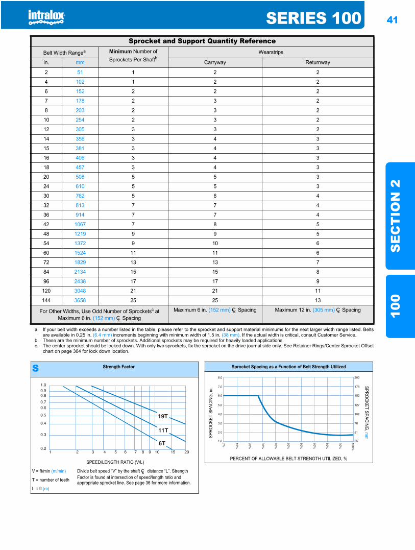
SERIES 100 41
SE
CT
ION
210
0
Sprocket and Support Quantity ReferenceBelt Width Rangea Minimum Number of
Sprockets Per ShaftbWearstrips
in. mm Carryway Returnway
2 51 1 2 2
4 102 1 2 2
6 152 2 2 2
7 178 2 3 2
8 203 2 3 2
10 254 2 3 2
12 305 3 3 2
14 356 3 4 3
15 381 3 4 3
16 406 3 4 3
18 457 3 4 3
20 508 5 5 3
24 610 5 5 3
30 762 5 6 4
32 813 7 7 4
36 914 7 7 4
42 1067 7 8 5
48 1219 9 9 5
54 1372 9 10 6
60 1524 11 11 6
72 1829 13 13 7
84 2134 15 15 8
96 2438 17 17 9
120 3048 21 21 11
144 3658 25 25 13
For Other Widths, Use Odd Number of Sprocketsc at Maximum 6 in. (152 mm) CL Spacing
Maximum 6 in. (152 mm) CL Spacing Maximum 12 in. (305 mm) CL Spacing
a. If your belt width exceeds a number listed in the table, please refer to the sprocket and support material minimums for the next larger width range listed. Beltsare available in 0.25 in. (6.4 mm) increments beginning with minimum width of 1.5 in. (38 mm). If the actual width is critical, consult Customer Service.
b. These are the minimum number of sprockets. Additional sprockets may be required for heavily loaded applications.c. The center sprocket should be locked down. With only two sprockets, fix the sprocket on the drive journal side only. See Retainer Rings/Center Sprocket Offset
chart on page 304 for lock down location.
S Strength Factor
SPEED/LENGTH RATIO (V/L)
V = ft/min (m/min) Divide belt speed “V” by the shaft CL distance “L”. Strength Factor is found at intersection of speed/length ratio and appropriate sprocket line. See page 36 for more information.T = number of teeth
L = ft (m)
1.00.90.8
0.70.6
0.5
0.4
0.3
0.21 2 3 4 5 6 7 8 9 10 15 20
Sprocket Spacing as a Function of Belt Strength Utilized
SPRO
CKET
SPA
CING
, in.
SPROCKET SPACING
, mm
PERCENT OF ALLOWABLE BELT STRENGTH UTILIZED, %
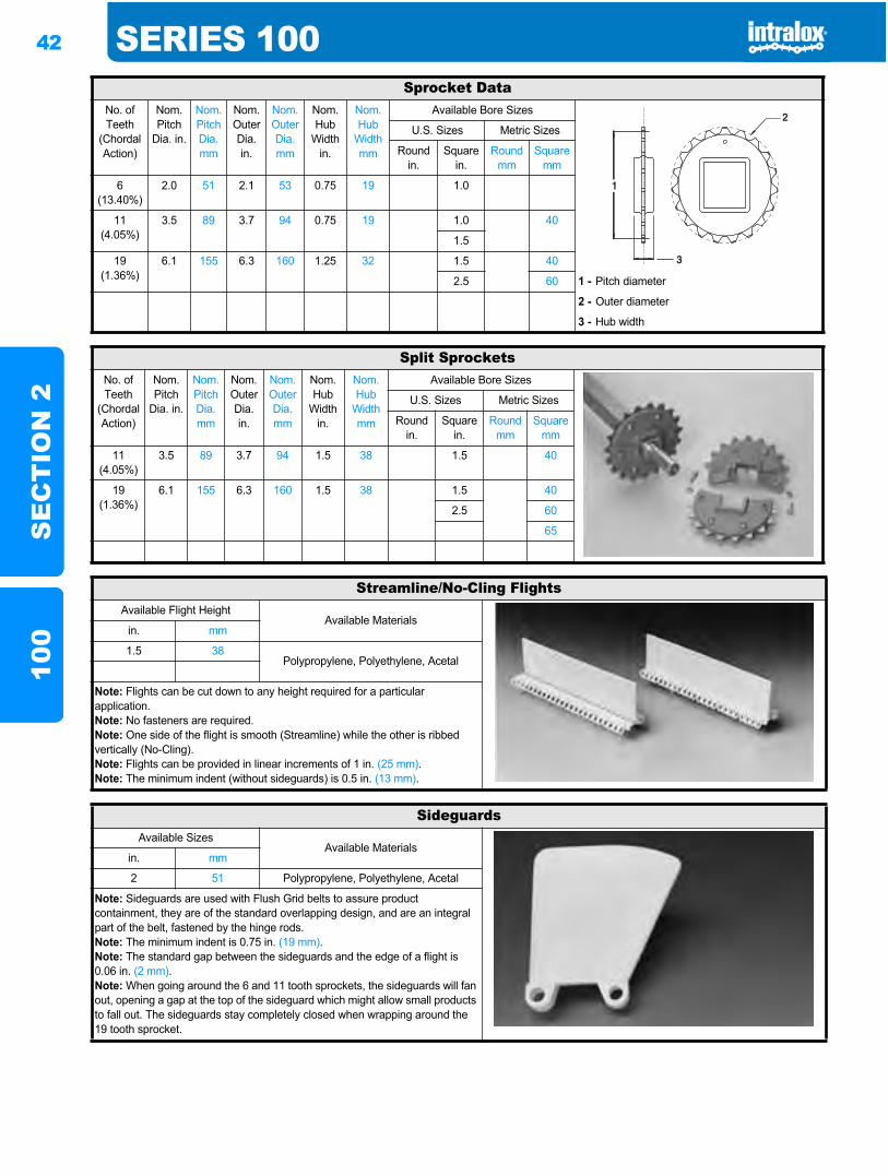
42 SERIES 100S
EC
TIO
N 2
100
Sprocket DataNo. of Teeth
(Chordal Action)
Nom. Pitch
Dia. in.
Nom. Pitch Dia. mm
Nom. Outer Dia. in.
Nom. Outer Dia.mm
Nom. Hub
Width in.
Nom. Hub
Width mm
Available Bore Sizes
U.S. Sizes Metric Sizes
Round in.
Square in.
Round mm
Square mm
6(13.40%)
2.0 51 2.1 53 0.75 19 1.0
11(4.05%)
3.5 89 3.7 94 0.75 19 1.0 40
1.5
19(1.36%)
6.1 155 6.3 160 1.25 32 1.5 40
2.5 60 1 - Pitch diameter
2 - Outer diameter
3 - Hub width
Split SprocketsNo. of Teeth
(Chordal Action)
Nom. Pitch
Dia. in.
Nom. Pitch Dia. mm
Nom. Outer Dia.in.
Nom. Outer Dia.mm
Nom. Hub
Width in.
Nom. Hub
Width mm
Available Bore Sizes
U.S. Sizes Metric Sizes
Round in.
Square in.
Round mm
Square mm
11(4.05%)
3.5 89 3.7 94 1.5 38 1.5 40
19(1.36%)
6.1 155 6.3 160 1.5 38 1.5 40
2.5 60
65
Streamline/No-Cling FlightsAvailable Flight Height
Available Materialsin. mm
1.5 38Polypropylene, Polyethylene, Acetal
Note: Flights can be cut down to any height required for a particular application.Note: No fasteners are required.Note: One side of the flight is smooth (Streamline) while the other is ribbed vertically (No-Cling).Note: Flights can be provided in linear increments of 1 in. (25 mm).Note: The minimum indent (without sideguards) is 0.5 in. (13 mm).
SideguardsAvailable Sizes
Available Materialsin. mm
2 51 Polypropylene, Polyethylene, Acetal
Note: Sideguards are used with Flush Grid belts to assure product containment, they are of the standard overlapping design, and are an integral part of the belt, fastened by the hinge rods.Note: The minimum indent is 0.75 in. (19 mm).Note: The standard gap between the sideguards and the edge of a flight is 0.06 in. (2 mm).Note: When going around the 6 and 11 tooth sprockets, the sideguards will fan out, opening a gap at the top of the sideguard which might allow small products to fall out. The sideguards stay completely closed when wrapping around the 19 tooth sprocket.
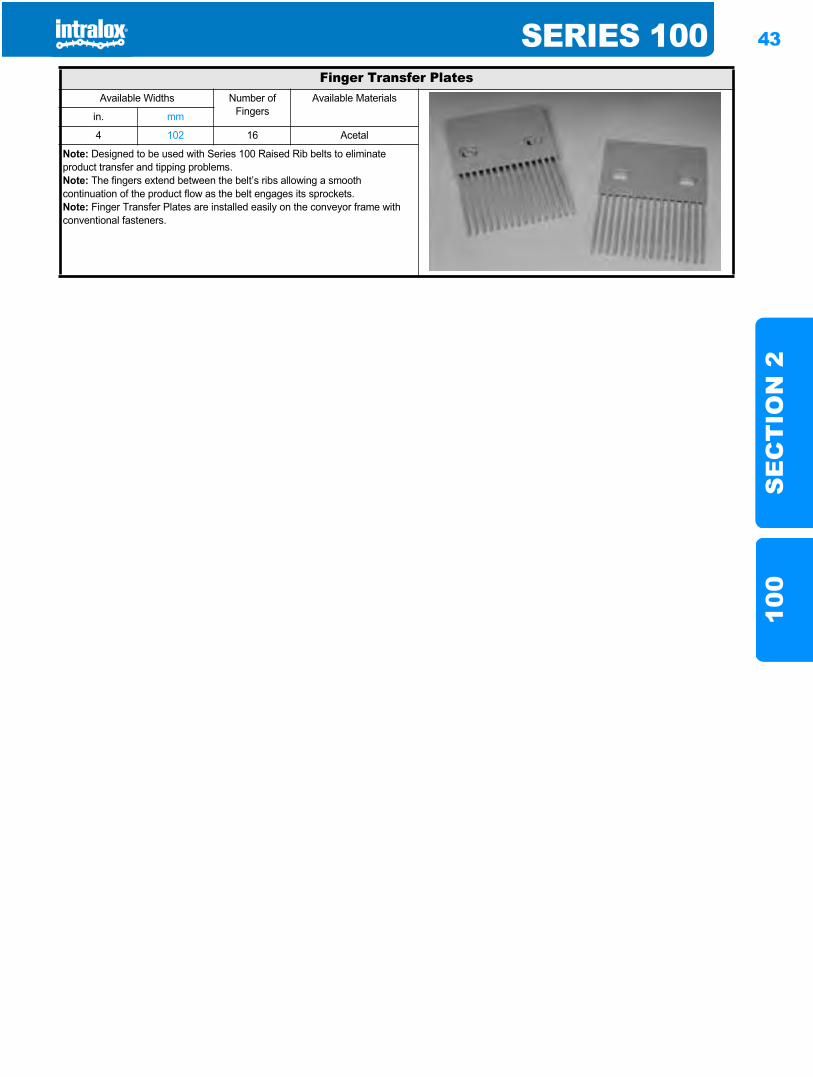
SERIES 100 43
SE
CT
ION
210
0
Finger Transfer PlatesAvailable Widths Number of
FingersAvailable Materials
in. mm
4 102 16 Acetal
Note: Designed to be used with Series 100 Raised Rib belts to eliminate product transfer and tipping problems.Note: The fingers extend between the belt’s ribs allowing a smooth continuation of the product flow as the belt engages its sprockets.Note: Finger Transfer Plates are installed easily on the conveyor frame with conventional fasteners.
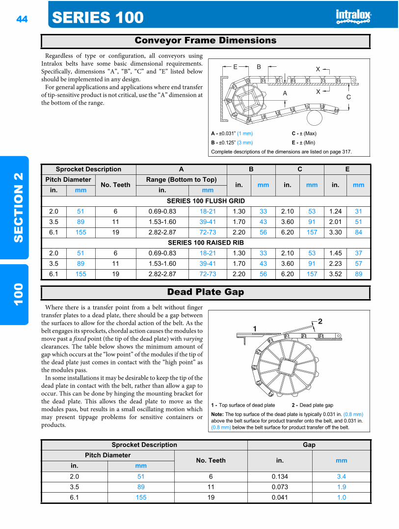
44 SERIES 100S
EC
TIO
N 2
100
Regardless of type or configuration, all conveyors usingIntralox belts have some basic dimensional requirements.Specifically, dimensions “A”, “B”, “C” and “E” listed belowshould be implemented in any design.
For general applications and applications where end transferof tip-sensitive product is not critical, use the “A” dimension atthe bottom of the range.
Where there is a transfer point from a belt without fingertransfer plates to a dead plate, there should be a gap betweenthe surfaces to allow for the chordal action of the belt. As thebelt engages its sprockets, chordal action causes the modules tomove past a fixed point (the tip of the dead plate) with varyingclearances. The table below shows the minimum amount ofgap which occurs at the “low point” of the modules if the tip ofthe dead plate just comes in contact with the “high point” asthe modules pass.
In some installations it may be desirable to keep the tip of thedead plate in contact with the belt, rather than allow a gap tooccur. This can be done by hinging the mounting bracket forthe dead plate. This allows the dead plate to move as themodules pass, but results in a small oscillating motion whichmay present tippage problems for sensitive containers orproducts.
Conveyor Frame Dimensions
A - ±0.031” (1 mm) C - ± (Max)
B - ±0.125” (3 mm) E - ± (Min)
Complete descriptions of the dimensions are listed on page 317.
Sprocket Description A B C EPitch Diameter
No. TeethRange (Bottom to Top)
in. mm in. mm in. mmin. mm in. mm
SERIES 100 FLUSH GRID2.0 51 6 0.69-0.83 18-21 1.30 33 2.10 53 1.24 313.5 89 11 1.53-1.60 39-41 1.70 43 3.60 91 2.01 516.1 155 19 2.82-2.87 72-73 2.20 56 6.20 157 3.30 84
SERIES 100 RAISED RIB2.0 51 6 0.69-0.83 18-21 1.30 33 2.10 53 1.45 373.5 89 11 1.53-1.60 39-41 1.70 43 3.60 91 2.23 576.1 155 19 2.82-2.87 72-73 2.20 56 6.20 157 3.52 89
Dead Plate Gap
1 - Top surface of dead plate 2 - Dead plate gap
Note: The top surface of the dead plate is typically 0.031 in. (0.8 mm)above the belt surface for product transfer onto the belt, and 0.031 in. (0.8 mm) below the belt surface for product transfer off the belt.
21
Sprocket Description GapPitch Diameter
No. Teeth in. mmin. mm2.0 51 6 0.134 3.43.5 89 11 0.073 1.96.1 155 19 0.041 1.0
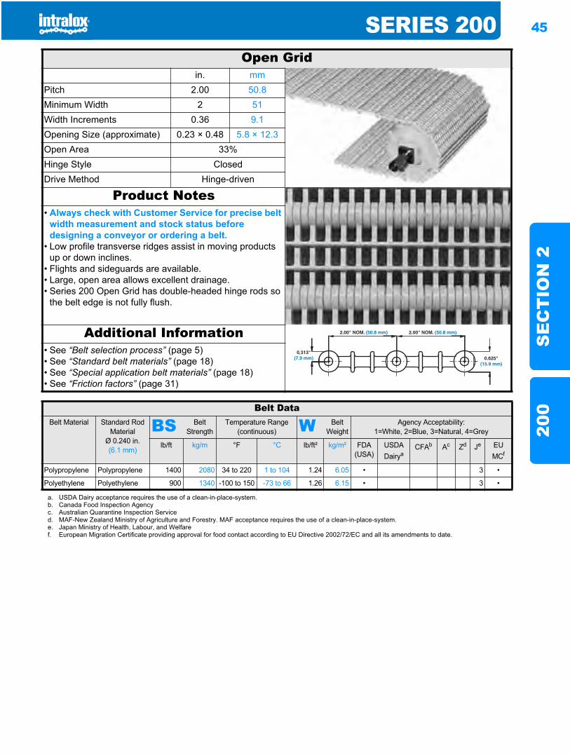
SERIES 200 45
SE
CT
ION
220
0
Series 200200
Open Gridin. mm
Pitch 2.00 50.8Minimum Width 2 51Width Increments 0.36 9.1Opening Size (approximate) 0.23 × 0.48 5.8 × 12.3Open Area 33%Hinge Style ClosedDrive Method Hinge-driven
Product Notes• Always check with Customer Service for precise belt
width measurement and stock status before designing a conveyor or ordering a belt.
• Low profile transverse ridges assist in moving products up or down inclines.
• Flights and sideguards are available.• Large, open area allows excellent drainage.• Series 200 Open Grid has double-headed hinge rods so
the belt edge is not fully flush.
Additional Information• See “Belt selection process” (page 5)• See “Standard belt materials” (page 18)• See “Special application belt materials” (page 18)• See “Friction factors” (page 31)
Belt DataBelt Material Standard Rod
MaterialØ 0.240 in. (6.1 mm)
BS Belt Strength
Temperature Range (continuous) W Belt
WeightAgency Acceptability:
1=White, 2=Blue, 3=Natural, 4=Grey
lb/ft kg/m °F °C lb/ft² kg/m² FDA(USA)
USDADairya
CFAb Ac Zd Je EU MCf
Polypropylene Polypropylene 1400 2080 34 to 220 1 to 104 1.24 6.05 • 3 •
Polyethylene Polyethylene 900 1340 -100 to 150 -73 to 66 1.26 6.15 • 3 •
a. USDA Dairy acceptance requires the use of a clean-in-place-system.b. Canada Food Inspection Agencyc. Australian Quarantine Inspection Serviced. MAF-New Zealand Ministry of Agriculture and Forestry. MAF acceptance requires the use of a clean-in-place-system.e. Japan Ministry of Health, Labour, and Welfaref. European Migration Certificate providing approval for food contact according to EU Directive 2002/72/EC and all its amendments to date.
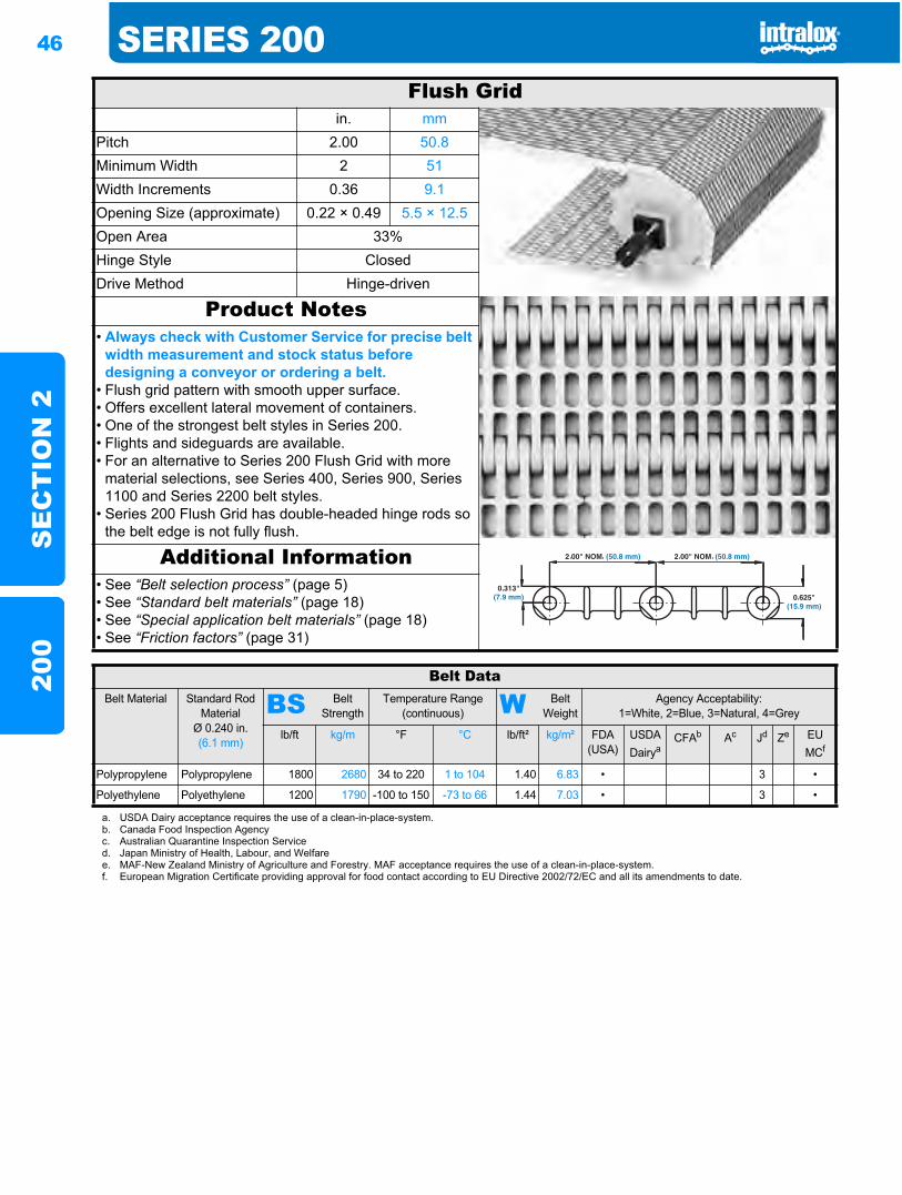
46 SERIES 200S
EC
TIO
N 2
200
Flush Gridin. mm
Pitch 2.00 50.8Minimum Width 2 51Width Increments 0.36 9.1Opening Size (approximate) 0.22 × 0.49 5.5 × 12.5Open Area 33%Hinge Style ClosedDrive Method Hinge-driven
Product Notes• Always check with Customer Service for precise belt
width measurement and stock status before designing a conveyor or ordering a belt.
• Flush grid pattern with smooth upper surface.• Offers excellent lateral movement of containers.• One of the strongest belt styles in Series 200.• Flights and sideguards are available.• For an alternative to Series 200 Flush Grid with more
material selections, see Series 400, Series 900, Series 1100 and Series 2200 belt styles.
• Series 200 Flush Grid has double-headed hinge rods so the belt edge is not fully flush.
Additional Information• See “Belt selection process” (page 5)• See “Standard belt materials” (page 18)• See “Special application belt materials” (page 18)• See “Friction factors” (page 31)
Belt DataBelt Material Standard Rod
MaterialØ 0.240 in. (6.1 mm)
BS Belt Strength
Temperature Range (continuous) W Belt
WeightAgency Acceptability:
1=White, 2=Blue, 3=Natural, 4=Grey
lb/ft kg/m °F °C lb/ft² kg/m² FDA(USA)
USDADairya
CFAb Ac Jd Ze EU MCf
Polypropylene Polypropylene 1800 2680 34 to 220 1 to 104 1.40 6.83 • 3 •
Polyethylene Polyethylene 1200 1790 -100 to 150 -73 to 66 1.44 7.03 • 3 •
a. USDA Dairy acceptance requires the use of a clean-in-place-system.b. Canada Food Inspection Agencyc. Australian Quarantine Inspection Serviced. Japan Ministry of Health, Labour, and Welfaree. MAF-New Zealand Ministry of Agriculture and Forestry. MAF acceptance requires the use of a clean-in-place-system.f. European Migration Certificate providing approval for food contact according to EU Directive 2002/72/EC and all its amendments to date.
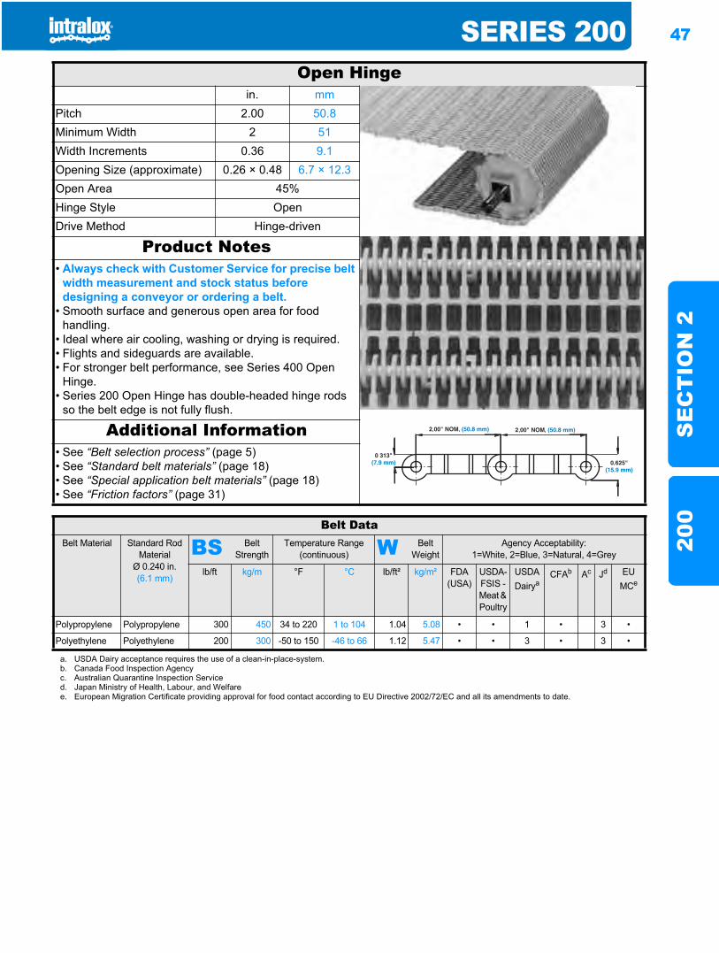
SERIES 200 47
SE
CT
ION
220
0
Open Hingein. mm
Pitch 2.00 50.8Minimum Width 2 51Width Increments 0.36 9.1Opening Size (approximate) 0.26 × 0.48 6.7 × 12.3Open Area 45%Hinge Style OpenDrive Method Hinge-driven
Product Notes• Always check with Customer Service for precise belt
width measurement and stock status before designing a conveyor or ordering a belt.
• Smooth surface and generous open area for food handling.
• Ideal where air cooling, washing or drying is required.• Flights and sideguards are available.• For stronger belt performance, see Series 400 Open
Hinge.• Series 200 Open Hinge has double-headed hinge rods
so the belt edge is not fully flush.
Additional Information• See “Belt selection process” (page 5)• See “Standard belt materials” (page 18)• See “Special application belt materials” (page 18)• See “Friction factors” (page 31)
Belt DataBelt Material Standard Rod
MaterialØ 0.240 in. (6.1 mm)
BS Belt Strength
Temperature Range (continuous) W Belt
WeightAgency Acceptability:
1=White, 2=Blue, 3=Natural, 4=Grey
lb/ft kg/m °F °C lb/ft² kg/m² FDA(USA)
USDA-FSIS - Meat & Poultry
USDADairya
CFAb Ac Jd EU MCe
Polypropylene Polypropylene 300 450 34 to 220 1 to 104 1.04 5.08 • • 1 • 3 •
Polyethylene Polyethylene 200 300 -50 to 150 -46 to 66 1.12 5.47 • • 3 • 3 •
a. USDA Dairy acceptance requires the use of a clean-in-place-system.b. Canada Food Inspection Agencyc. Australian Quarantine Inspection Serviced. Japan Ministry of Health, Labour, and Welfaree. European Migration Certificate providing approval for food contact according to EU Directive 2002/72/EC and all its amendments to date.
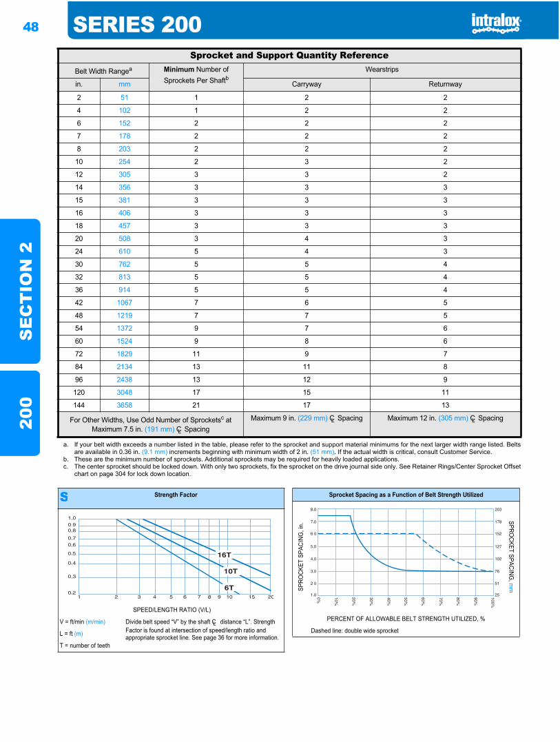
48 SERIES 200S
EC
TIO
N 2
200
Sprocket and Support Quantity ReferenceBelt Width Rangea Minimum Number of
Sprockets Per ShaftbWearstrips
in. mm Carryway Returnway
2 51 1 2 2
4 102 1 2 2
6 152 2 2 2
7 178 2 2 2
8 203 2 2 2
10 254 2 3 2
12 305 3 3 2
14 356 3 3 3
15 381 3 3 3
16 406 3 3 3
18 457 3 3 3
20 508 3 4 3
24 610 5 4 3
30 762 5 5 4
32 813 5 5 4
36 914 5 5 4
42 1067 7 6 5
48 1219 7 7 5
54 1372 9 7 6
60 1524 9 8 6
72 1829 11 9 7
84 2134 13 11 8
96 2438 13 12 9
120 3048 17 15 11
144 3658 21 17 13
For Other Widths, Use Odd Number of Sprocketsc at Maximum 7.5 in. (191 mm) CL Spacing
Maximum 9 in. (229 mm) CL Spacing Maximum 12 in. (305 mm) CL Spacing
a. If your belt width exceeds a number listed in the table, please refer to the sprocket and support material minimums for the next larger width range listed. Beltsare available in 0.36 in. (9.1 mm) increments beginning with minimum width of 2 in. (51 mm). If the actual width is critical, consult Customer Service.
b. These are the minimum number of sprockets. Additional sprockets may be required for heavily loaded applications.c. The center sprocket should be locked down. With only two sprockets, fix the sprocket on the drive journal side only. See Retainer Rings/Center Sprocket Offset
chart on page 304 for lock down location.
S Strength Factor
SPEED/LENGTH RATIO (V/L)
V = ft/min (m/min) Divide belt speed “V” by the shaft CL distance “L”. Strength Factor is found at intersection of speed/length ratio and appropriate sprocket line. See page 36 for more information.L = ft (m)
T = number of teeth
Sprocket Spacing as a Function of Belt Strength Utilized
SPRO
CKET
SPA
CING
, in.
SPROCKET SPACING
, mm
PERCENT OF ALLOWABLE BELT STRENGTH UTILIZED, %
Dashed line: double wide sprocket
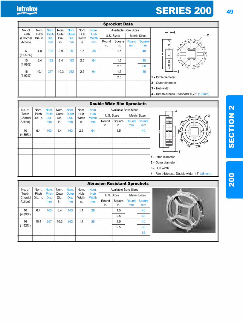
SERIES 200 49
SE
CT
ION
220
0
Sprocket DataNo. of Teeth
(Chordal Action)
Nom. Pitch
Dia. in.
Nom. Pitch Dia. mm
Nom. OuterDia. in.
Nom. OuterDia. mm
Nom. Hub
Width in.
Nom. Hub
Width mm
Available Bore Sizes
U.S. Sizes Metric Sizes
Round in.
Square in.
Round mm
Square mm
6(13.40%)
4.0 102 3.9 99 1.5 38 1.5 40
10 (4.89%)
6.4 163 6.4 163 2.5 64 1.5 40
2.5 60
16 (1.92%)
10.1 257 10.3 262 2.5 64 1.5 40
2.5 1 - Pitch diameter
2 - Outer diameter
3 - Hub width
4 - Rim thickness. Standard: 0,75” (19 mm)
Double Wide Rim SprocketsNo. of Teeth
(Chordal Action)
Nom. Pitch
Dia. in.
Nom. Pitch Dia. mm
Nom. Outer Dia.in.
Nom. Outer Dia.mm
Nom. Hub
Width in.
Nom. Hub
Width mm
Available Bore Sizes
U.S. Sizes Metric Sizes
Round in.
Square in.
Round mm
Square mm
10(4.89%)
6.4 163 6.4 163 2.5 64 1.5 40
1 - Pitch diameter
2 - Outer diameter
3 - Hub width
4 - Rim thickness. Double wide: 1.5” (38 mm)
Abrasion Resistant SprocketsNo. of Teeth
(Chordal Action)
Nom. Pitch
Dia. in.
Nom. Pitch Dia. mm
Nom. Outer Dia.in.
Nom. Outer Dia.mm
Nom. Hub
Width in.
Nom. Hub
Width mm
Available Bore Sizes
U.S. Sizes Metric Sizes
Round in.
Square in.
Round mm
Square mm
10(4.89%)
6.4 163 6.4 163 1.1 28 1.5 40
2.5 60
16(1.92%)
10.1 257 10.3 262 1.1 28 1.5 40
2.5 60
65
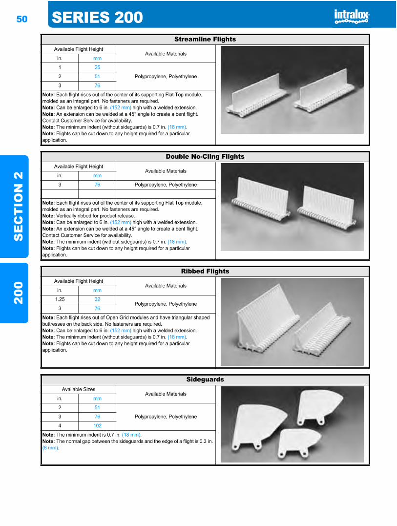
50 SERIES 200S
EC
TIO
N 2
200
Streamline FlightsAvailable Flight Height
Available Materialsin. mm
1 25
Polypropylene, Polyethylene2 51
3 76
Note: Each flight rises out of the center of its supporting Flat Top module, molded as an integral part. No fasteners are required.Note: Can be enlarged to 6 in. (152 mm) high with a welded extension.Note: An extension can be welded at a 45° angle to create a bent flight. Contact Customer Service for availability.Note: The minimum indent (without sideguards) is 0.7 in. (18 mm).Note: Flights can be cut down to any height required for a particular application.
Double No-Cling FlightsAvailable Flight Height
Available Materialsin. mm
3 76 Polypropylene, Polyethylene
Note: Each flight rises out of the center of its supporting Flat Top module, molded as an integral part. No fasteners are required.Note: Vertically ribbed for product release.Note: Can be enlarged to 6 in. (152 mm) high with a welded extension.Note: An extension can be welded at a 45° angle to create a bent flight. Contact Customer Service for availability.Note: The minimum indent (without sideguards) is 0.7 in. (18 mm).Note: Flights can be cut down to any height required for a particular application.
Ribbed FlightsAvailable Flight Height
Available Materialsin. mm
1.25 32Polypropylene, Polyethylene
3 76
Note: Each flight rises out of Open Grid modules and have triangular shaped buttresses on the back side. No fasteners are required.Note: Can be enlarged to 6 in. (152 mm) high with a welded extension.Note: The minimum indent (without sideguards) is 0.7 in. (18 mm).Note: Flights can be cut down to any height required for a particular application.
SideguardsAvailable Sizes
Available Materialsin. mm
2 51
Polypropylene, Polyethylene3 76
4 102
Note: The minimum indent is 0.7 in. (18 mm).Note: The normal gap between the sideguards and the edge of a flight is 0.3 in. (8 mm).
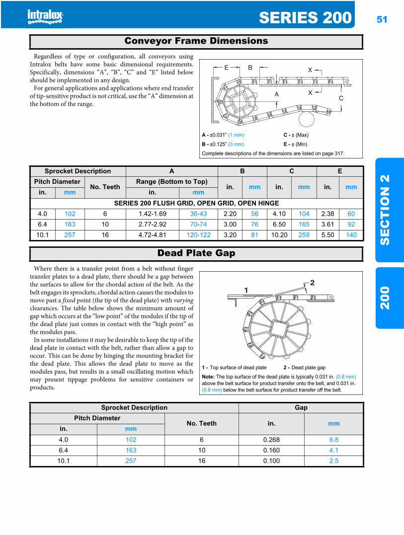
SERIES 200 51
SE
CT
ION
220
0
Regardless of type or configuration, all conveyors usingIntralox belts have some basic dimensional requirements.Specifically, dimensions “A”, “B”, “C” and “E” listed belowshould be implemented in any design.
For general applications and applications where end transferof tip-sensitive product is not critical, use the “A” dimension atthe bottom of the range.
Where there is a transfer point from a belt without fingertransfer plates to a dead plate, there should be a gap betweenthe surfaces to allow for the chordal action of the belt. As thebelt engages its sprockets, chordal action causes the modules tomove past a fixed point (the tip of the dead plate) with varyingclearances. The table below shows the minimum amount ofgap which occurs at the “low point” of the modules if the tip ofthe dead plate just comes in contact with the “high point” asthe modules pass.
In some installations it may be desirable to keep the tip of thedead plate in contact with the belt, rather than allow a gap tooccur. This can be done by hinging the mounting bracket forthe dead plate. This allows the dead plate to move as themodules pass, but results in a small oscillating motion whichmay present tippage problems for sensitive containers orproducts.
Conveyor Frame Dimensions
A - ±0.031” (1 mm) C - ± (Max)
B - ±0.125” (3 mm) E - ± (Min)
Complete descriptions of the dimensions are listed on page 317.
Sprocket Description A B C EPitch Diameter
No. TeethRange (Bottom to Top)
in. mm in. mm in. mmin. mm in. mm
SERIES 200 FLUSH GRID, OPEN GRID, OPEN HINGE4.0 102 6 1.42-1.69 36-43 2.20 56 4.10 104 2.38 606.4 163 10 2.77-2.92 70-74 3.00 76 6.50 165 3.61 9210.1 257 16 4.72-4.81 120-122 3.20 81 10.20 259 5.50 140
Dead Plate Gap
1 - Top surface of dead plate 2 - Dead plate gap
Note: The top surface of the dead plate is typically 0.031 in. (0.8 mm)above the belt surface for product transfer onto the belt, and 0.031 in. (0.8 mm) below the belt surface for product transfer off the belt.
21
Sprocket Description GapPitch Diameter
No. Teeth in. mmin. mm4.0 102 6 0.268 6.86.4 163 10 0.160 4.1
10.1 257 16 0.100 2.5

52 SERIES 200S
EC
TIO
N 2
200
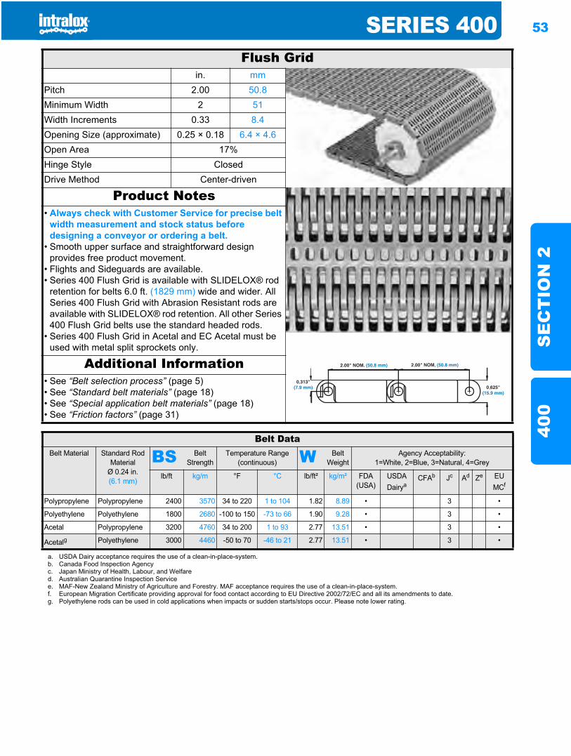
SERIES 400 53
SE
CT
ION
240
0
Series 400400
Flush Gridin. mm
Pitch 2.00 50.8Minimum Width 2 51Width Increments 0.33 8.4Opening Size (approximate) 0.25 × 0.18 6.4 × 4.6Open Area 17%Hinge Style ClosedDrive Method Center-driven
Product Notes• Always check with Customer Service for precise belt
width measurement and stock status before designing a conveyor or ordering a belt.
• Smooth upper surface and straightforward design provides free product movement.
• Flights and Sideguards are available.• Series 400 Flush Grid is available with SLIDELOX® rod
retention for belts 6.0 ft. (1829 mm) wide and wider. All Series 400 Flush Grid with Abrasion Resistant rods are available with SLIDELOX® rod retention. All other Series 400 Flush Grid belts use the standard headed rods.
• Series 400 Flush Grid in Acetal and EC Acetal must be used with metal split sprockets only.
Additional Information• See “Belt selection process” (page 5)• See “Standard belt materials” (page 18)• See “Special application belt materials” (page 18)• See “Friction factors” (page 31)
Belt DataBelt Material Standard Rod
MaterialØ 0.24 in. (6.1 mm)
BS Belt Strength
Temperature Range (continuous) W Belt
WeightAgency Acceptability:
1=White, 2=Blue, 3=Natural, 4=Grey
lb/ft kg/m °F °C lb/ft² kg/m² FDA (USA)
USDADairya
CFAb Jc Ad Ze EU MCf
Polypropylene Polypropylene 2400 3570 34 to 220 1 to 104 1.82 8.89 • 3 •
Polyethylene Polyethylene 1800 2680 -100 to 150 -73 to 66 1.90 9.28 • 3 •
Acetal Polypropylene 3200 4760 34 to 200 1 to 93 2.77 13.51 • 3 •
Acetalg Polyethylene 3000 4460 -50 to 70 -46 to 21 2.77 13.51 • 3 •
a. USDA Dairy acceptance requires the use of a clean-in-place-system.b. Canada Food Inspection Agencyc. Japan Ministry of Health, Labour, and Welfared. Australian Quarantine Inspection Servicee. MAF-New Zealand Ministry of Agriculture and Forestry. MAF acceptance requires the use of a clean-in-place-system.f. European Migration Certificate providing approval for food contact according to EU Directive 2002/72/EC and all its amendments to date.g. Polyethylene rods can be used in cold applications when impacts or sudden starts/stops occur. Please note lower rating.
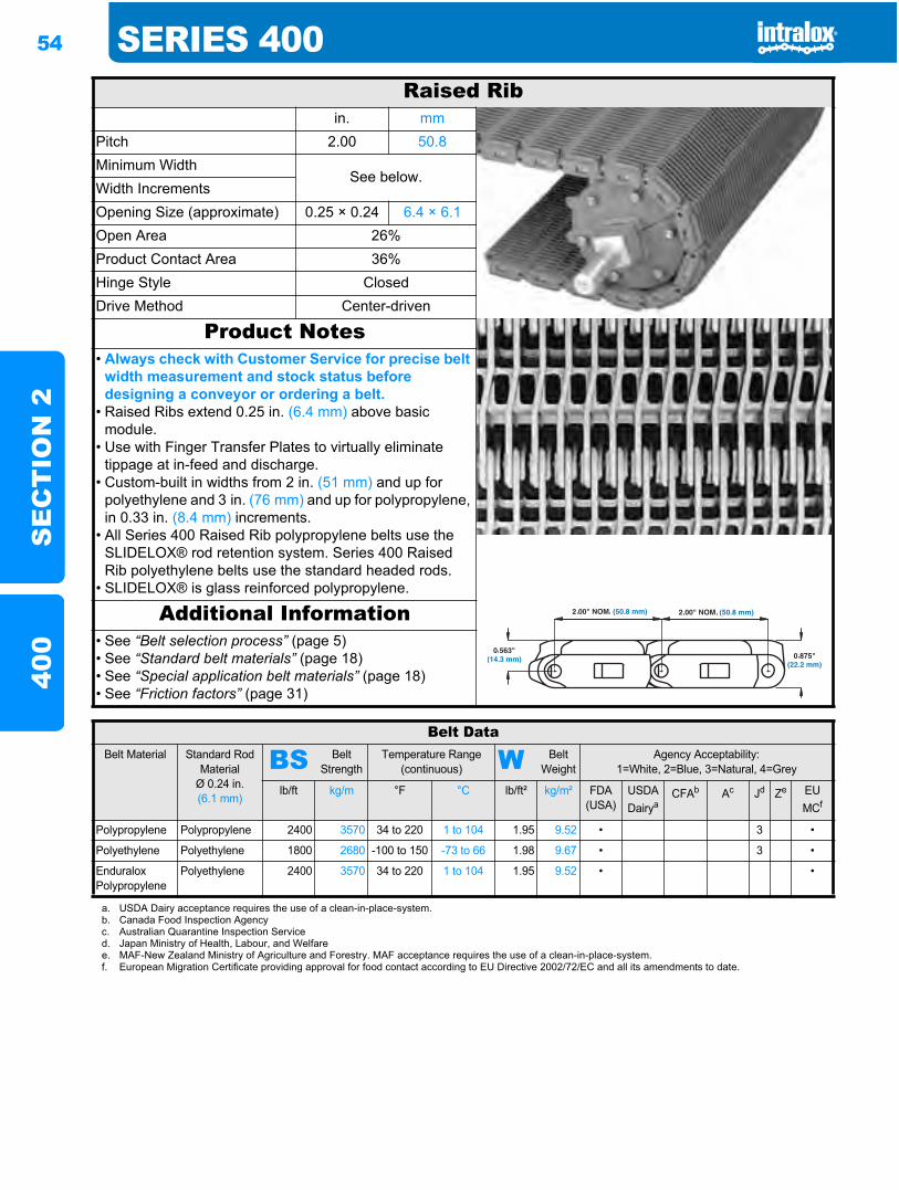
54 SERIES 400S
EC
TIO
N 2
400
Raised Ribin. mm
Pitch 2.00 50.8Minimum Width
See below.Width IncrementsOpening Size (approximate) 0.25 × 0.24 6.4 × 6.1Open Area 26%Product Contact Area 36%Hinge Style ClosedDrive Method Center-driven
Product Notes• Always check with Customer Service for precise belt
width measurement and stock status before designing a conveyor or ordering a belt.
• Raised Ribs extend 0.25 in. (6.4 mm) above basic module.
• Use with Finger Transfer Plates to virtually eliminate tippage at in-feed and discharge.
• Custom-built in widths from 2 in. (51 mm) and up for polyethylene and 3 in. (76 mm) and up for polypropylene, in 0.33 in. (8.4 mm) increments.
• All Series 400 Raised Rib polypropylene belts use the SLIDELOX® rod retention system. Series 400 Raised Rib polyethylene belts use the standard headed rods.
• SLIDELOX® is glass reinforced polypropylene.
Additional Information• See “Belt selection process” (page 5)• See “Standard belt materials” (page 18)• See “Special application belt materials” (page 18)• See “Friction factors” (page 31)
Belt DataBelt Material Standard Rod
MaterialØ 0.24 in. (6.1 mm)
BS Belt Strength
Temperature Range (continuous) W Belt
WeightAgency Acceptability:
1=White, 2=Blue, 3=Natural, 4=Grey
lb/ft kg/m °F °C lb/ft² kg/m² FDA(USA)
USDADairya
CFAb Ac Jd Ze EU MCf
Polypropylene Polypropylene 2400 3570 34 to 220 1 to 104 1.95 9.52 • 3 •
Polyethylene Polyethylene 1800 2680 -100 to 150 -73 to 66 1.98 9.67 • 3 •
Enduralox Polypropylene
Polyethylene 2400 3570 34 to 220 1 to 104 1.95 9.52 • •
a. USDA Dairy acceptance requires the use of a clean-in-place-system.b. Canada Food Inspection Agencyc. Australian Quarantine Inspection Serviced. Japan Ministry of Health, Labour, and Welfaree. MAF-New Zealand Ministry of Agriculture and Forestry. MAF acceptance requires the use of a clean-in-place-system.f. European Migration Certificate providing approval for food contact according to EU Directive 2002/72/EC and all its amendments to date.
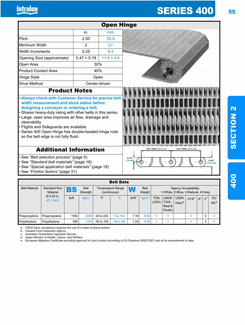
SERIES 400 55
SE
CT
ION
240
0
Open Hingein. mm
Pitch 2.00 50.8Minimum Width 2 51Width Increments 0.25 6.4Opening Size (approximate) 0.47 × 0.18 11.9 × 4.6Open Area 30%Product Contact Area 40%Hinge Style OpenDrive Method Center-driven
Product Notes• Always check with Customer Service for precise belt
width measurement and stock status before designing a conveyor or ordering a belt.
• Shares heavy-duty rating with other belts in this series.• Large, open area improves air flow, drainage and
cleanability.• Flights and Sideguards are available.• Series 400 Open Hinge has double-headed hinge rods
so the belt edge is not fully flush.
Additional Information• See “Belt selection process” (page 5)• See “Standard belt materials” (page 18)• See “Special application belt materials” (page 18)• See “Friction factors” (page 31)
Belt DataBelt Material Standard Rod
MaterialØ 0.24 in. (6.1 mm)
BS Belt Strength
Temperature Range (continuous) W Belt
WeightAgency Acceptability:
1=White, 2=Blue, 3=Natural, 4=Grey
lb/ft kg/m °F °C lb/ft² kg/m² FDA(USA)
USDA-FSIS - Meat & Poultry
USDADairya
CFAb Ac Jd EU MCe
Polypropylene Polypropylene 1550 2300 34 to 220 1 to 104 1.16 5.66 • • • 3 •
Polyethylene Polyethylene 950 1400 -50 to 150 -46 to 66 1.24 6.06 • • • 3 •
a. USDA Dairy acceptance requires the use of a clean-in-place-system.b. Canada Food Inspection Agencyc. Australian Quarantine Inspection Serviced. Japan Ministry of Health, Labour, and Welfaree. European Migration Certificate providing approval for food contact according to EU Directive 2002/72/EC and all its amendments to date.
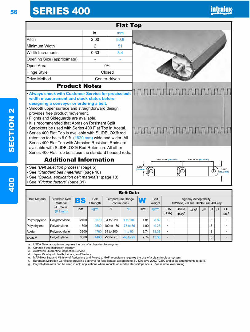
56 SERIES 400S
EC
TIO
N 2
400
Flat Topin. mm
Pitch 2.00 50.8Minimum Width 2 51Width Increments 0.33 8.4Opening Size (approximate) - -Open Area 0%Hinge Style ClosedDrive Method Center-driven
Product Notes• Always check with Customer Service for precise belt
width measurement and stock status before designing a conveyor or ordering a belt.
• Smooth upper surface and straightforward design provides free product movement.
• Flights and Sideguards are available.• It is recommended that Abrasion Resistant Split
Sprockets be used with Series 400 Flat Top in Acetal.• Series 400 Flat Top is available with SLIDELOX® rod
retention for belts 6.0 ft. (1829 mm) wide and wider. All Series 400 Flat Top with Abrasion Resistant Rods are available with SLIDELOX® Rod Retention. All other Series 400 Flat Top belts use the standard headed rods.
Additional Information• See “Belt selection process” (page 5)• See “Standard belt materials” (page 18)• See “Special application belt materials” (page 18)• See “Friction factors” (page 31)
Belt DataBelt Material Standard Rod
MaterialØ 0.24 in. (6.1 mm)
BS Belt Strength
Temperature Range (continuous) W Belt
WeightAgency Acceptability:
1=White, 2=Blue, 3=Natural, 4=Grey
lb/ft kg/m °F °C lb/ft² kg/m² FDA(USA)
USDADairya
CFAb Ac Jd Ze EUMCf
Polypropylene Polypropylene 2400 3570 34 to 220 1 to 104 1.81 8.82 • 3 •
Polyethylene Polyethylene 1800 2680 -100 to 150 -73 to 66 1.90 9.28 • 3 •
Acetal Polypropylene 3200 4760 34 to 200 1 to 93 2.74 13.38 • 3 •
Acetalg Polyethylene 3000 4460 -50 to 70 -46 to 21 2.74 13.38 • 3 •
a. USDA Dairy acceptance requires the use of a clean-in-place-system.b. Canada Food Inspection Agencyc. Australian Quarantine Inspection Serviced. Japan Ministry of Health, Labour, and Welfaree. MAF-New Zealand Ministry of Agriculture and Forestry. MAF acceptance requires the use of a clean-in-place-system.f. European Migration Certificate providing approval for food contact according to EU Directive 2002/72/EC and all its amendments to date.g. Polyethylene rods can be used in cold applications when impacts or sudden starts/stops occur. Please note lower rating.
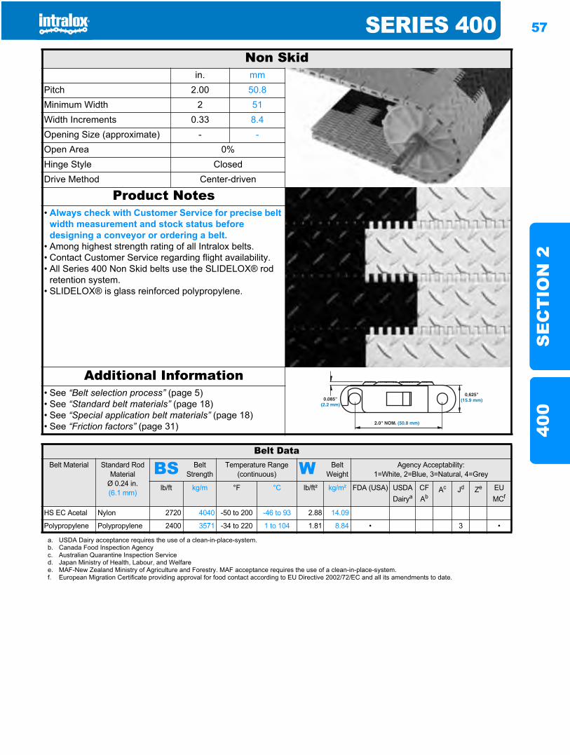
SERIES 400 57
SE
CT
ION
240
0
Non Skidin. mm
Pitch 2.00 50.8Minimum Width 2 51Width Increments 0.33 8.4Opening Size (approximate) - -Open Area 0%Hinge Style ClosedDrive Method Center-driven
Product Notes• Always check with Customer Service for precise belt
width measurement and stock status before designing a conveyor or ordering a belt.
• Among highest strength rating of all Intralox belts.• Contact Customer Service regarding flight availability.• All Series 400 Non Skid belts use the SLIDELOX® rod
retention system. • SLIDELOX® is glass reinforced polypropylene.
Additional Information• See “Belt selection process” (page 5)• See “Standard belt materials” (page 18)• See “Special application belt materials” (page 18)• See “Friction factors” (page 31)
Belt DataBelt Material Standard Rod
MaterialØ 0.24 in. (6.1 mm)
BS Belt Strength
Temperature Range (continuous) W Belt
WeightAgency Acceptability:
1=White, 2=Blue, 3=Natural, 4=Grey
lb/ft kg/m °F °C lb/ft² kg/m² FDA (USA) USDADairya
CFAb
Ac Jd Ze EU MCf
HS EC Acetal Nylon 2720 4040 -50 to 200 -46 to 93 2.88 14.09
Polypropylene Polypropylene 2400 3571 -34 to 220 1 to 104 1.81 8.84 • 3 •
a. USDA Dairy acceptance requires the use of a clean-in-place-system.b. Canada Food Inspection Agencyc. Australian Quarantine Inspection Serviced. Japan Ministry of Health, Labour, and Welfaree. MAF-New Zealand Ministry of Agriculture and Forestry. MAF acceptance requires the use of a clean-in-place-system.f. European Migration Certificate providing approval for food contact according to EU Directive 2002/72/EC and all its amendments to date.
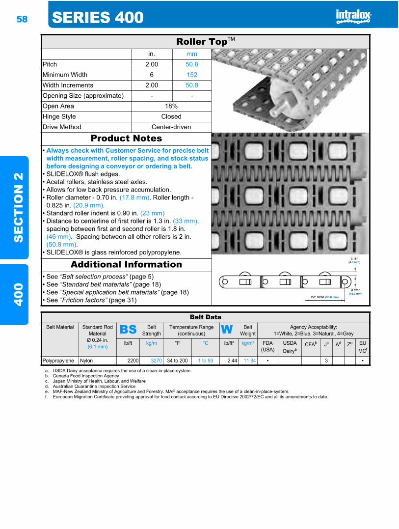
58 SERIES 400S
EC
TIO
N 2
400
Roller TopTM
in. mmPitch 2.00 50.8Minimum Width 6 152Width Increments 2.00 50.8Opening Size (approximate) - -Open Area 18%Hinge Style ClosedDrive Method Center-driven
Product Notes• Always check with Customer Service for precise belt
width measurement, roller spacing, and stock status before designing a conveyor or ordering a belt.
• SLIDELOX® flush edges.• Acetal rollers, stainless steel axles.• Allows for low back pressure accumulation.• Roller diameter - 0.70 in. (17.8 mm). Roller length -
0.825 in. (20.9 mm).• Standard roller indent is 0.90 in. (23 mm)• Distance to centerline of first roller is 1.3 in. (33 mm),
spacing between first and second roller is 1.8 in. (46 mm). Spacing between all other rollers is 2 in. (50.8 mm).
• SLIDELOX® is glass reinforced polypropylene.
Additional Information• See “Belt selection process” (page 5)• See “Standard belt materials” (page 18)• See “Special application belt materials” (page 18)• See “Friction factors” (page 31)
Belt DataBelt Material Standard Rod
MaterialØ 0.24 in. (6.1 mm)
BS Belt Strength
Temperature Range (continuous) W Belt
WeightAgency Acceptability:
1=White, 2=Blue, 3=Natural, 4=Grey
lb/ft kg/m °F °C lb/ft² kg/m² FDA(USA)
USDADairya
CFAb Jc Ad Ze EU MCf
Polypropylene Nylon 2200 3270 34 to 200 1 to 93 2.44 11.94 • 3 •
a. USDA Dairy acceptance requires the use of a clean-in-place-system.b. Canada Food Inspection Agencyc. Japan Ministry of Health, Labour, and Welfared. Australian Quarantine Inspection Servicee. MAF-New Zealand Ministry of Agriculture and Forestry. MAF acceptance requires the use of a clean-in-place-system.f. European Migration Certificate providing approval for food contact according to EU Directive 2002/72/EC and all its amendments to date.
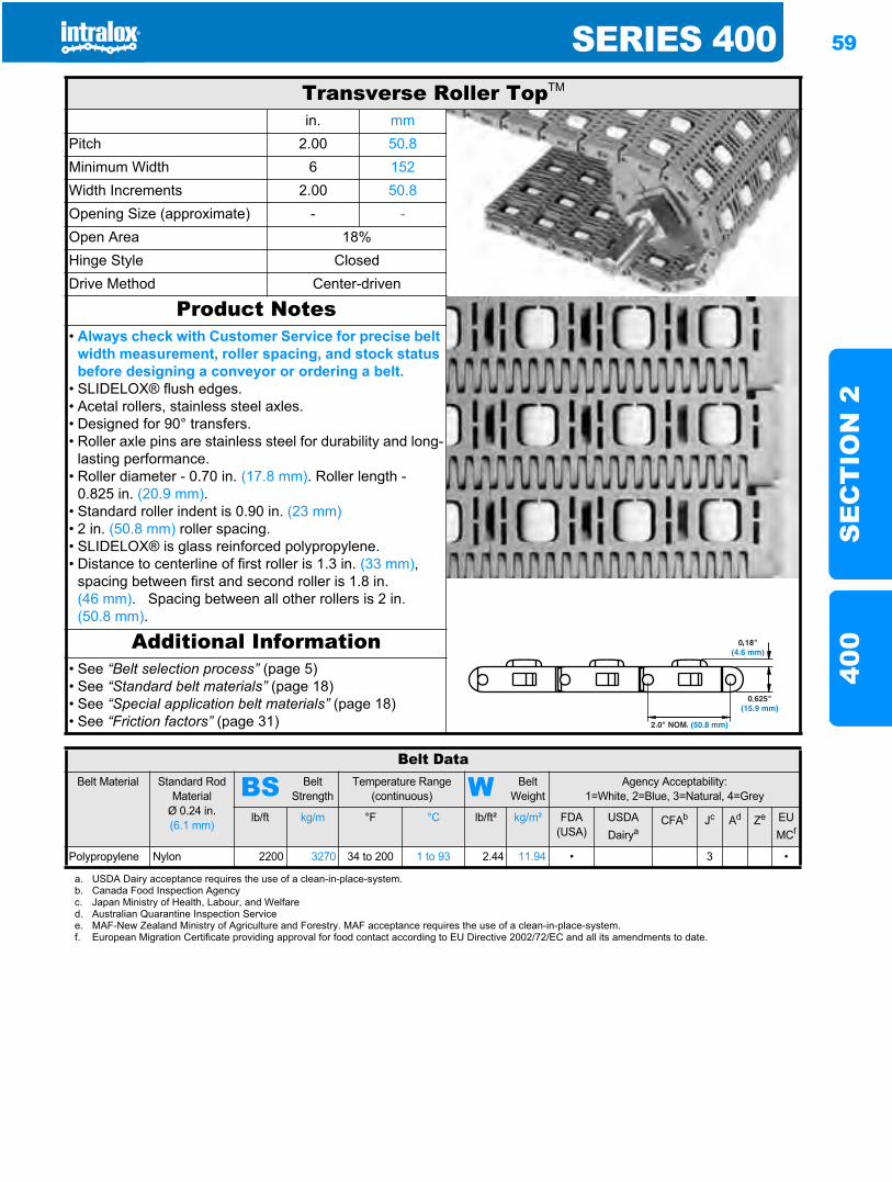
SERIES 400 59
SE
CT
ION
240
0
Transverse Roller TopTM
in. mmPitch 2.00 50.8Minimum Width 6 152Width Increments 2.00 50.8Opening Size (approximate) - -Open Area 18%Hinge Style ClosedDrive Method Center-driven
Product Notes• Always check with Customer Service for precise belt
width measurement, roller spacing, and stock status before designing a conveyor or ordering a belt.
• SLIDELOX® flush edges.• Acetal rollers, stainless steel axles.• Designed for 90° transfers.• Roller axle pins are stainless steel for durability and long-
lasting performance.• Roller diameter - 0.70 in. (17.8 mm). Roller length -
0.825 in. (20.9 mm).• Standard roller indent is 0.90 in. (23 mm)• 2 in. (50.8 mm) roller spacing.• SLIDELOX® is glass reinforced polypropylene.• Distance to centerline of first roller is 1.3 in. (33 mm),
spacing between first and second roller is 1.8 in. (46 mm). Spacing between all other rollers is 2 in. (50.8 mm).
Additional Information• See “Belt selection process” (page 5)• See “Standard belt materials” (page 18)• See “Special application belt materials” (page 18)• See “Friction factors” (page 31)
Belt DataBelt Material Standard Rod
MaterialØ 0.24 in. (6.1 mm)
BS Belt Strength
Temperature Range (continuous) W Belt
WeightAgency Acceptability:
1=White, 2=Blue, 3=Natural, 4=Grey
lb/ft kg/m °F °C lb/ft² kg/m² FDA (USA)
USDADairya
CFAb Jc Ad Ze EU MCf
Polypropylene Nylon 2200 3270 34 to 200 1 to 93 2.44 11.94 • 3 •
a. USDA Dairy acceptance requires the use of a clean-in-place-system.b. Canada Food Inspection Agencyc. Japan Ministry of Health, Labour, and Welfared. Australian Quarantine Inspection Servicee. MAF-New Zealand Ministry of Agriculture and Forestry. MAF acceptance requires the use of a clean-in-place-system.f. European Migration Certificate providing approval for food contact according to EU Directive 2002/72/EC and all its amendments to date.
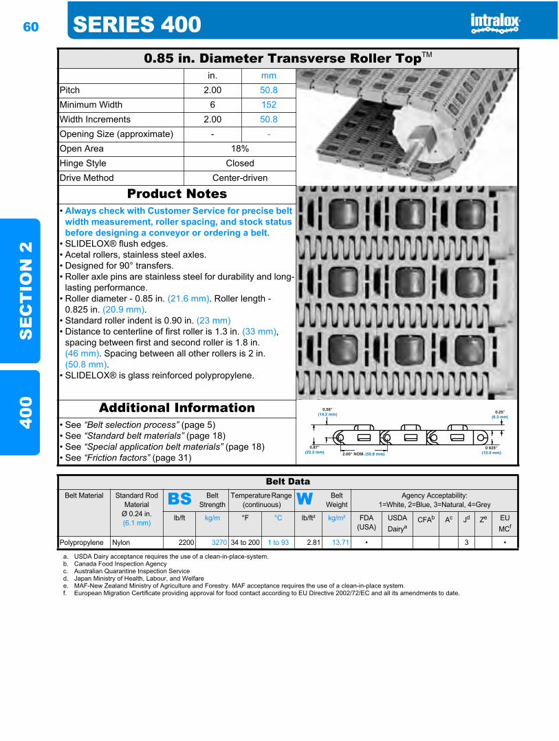
60 SERIES 400S
EC
TIO
N 2
400
0.85 in. Diameter Transverse Roller TopTM
in. mmPitch 2.00 50.8Minimum Width 6 152Width Increments 2.00 50.8Opening Size (approximate) - -Open Area 18%Hinge Style ClosedDrive Method Center-driven
Product Notes• Always check with Customer Service for precise belt
width measurement, roller spacing, and stock status before designing a conveyor or ordering a belt.
• SLIDELOX® flush edges.• Acetal rollers, stainless steel axles.• Designed for 90° transfers.• Roller axle pins are stainless steel for durability and long-
lasting performance.• Roller diameter - 0.85 in. (21.6 mm). Roller length -
0.825 in. (20.9 mm).• Standard roller indent is 0.90 in. (23 mm)• Distance to centerline of first roller is 1.3 in. (33 mm),
spacing between first and second roller is 1.8 in. (46 mm). Spacing between all other rollers is 2 in. (50.8 mm).
• SLIDELOX® is glass reinforced polypropylene.
Additional Information• See “Belt selection process” (page 5)• See “Standard belt materials” (page 18)• See “Special application belt materials” (page 18)• See “Friction factors” (page 31)
Belt DataBelt Material Standard Rod
MaterialØ 0.24 in. (6.1 mm)
BS Belt Strength
Temperature Range (continuous) W Belt
WeightAgency Acceptability:
1=White, 2=Blue, 3=Natural, 4=Grey
lb/ft kg/m °F °C lb/ft² kg/m² FDA(USA)
USDADairya
CFAb Ac Jd Ze EUMCf
Polypropylene Nylon 2200 3270 34 to 200 1 to 93 2.81 13.71 • 3 •
a. USDA Dairy acceptance requires the use of a clean-in-place-system.b. Canada Food Inspection Agencyc. Australian Quarantine Inspection Serviced. Japan Ministry of Health, Labour, and Welfaree. MAF-New Zealand Ministry of Agriculture and Forestry. MAF acceptance requires the use of a clean-in-place system.f. European Migration Certificate providing approval for food contact according to EU Directive 2002/72/EC and all its amendments to date.
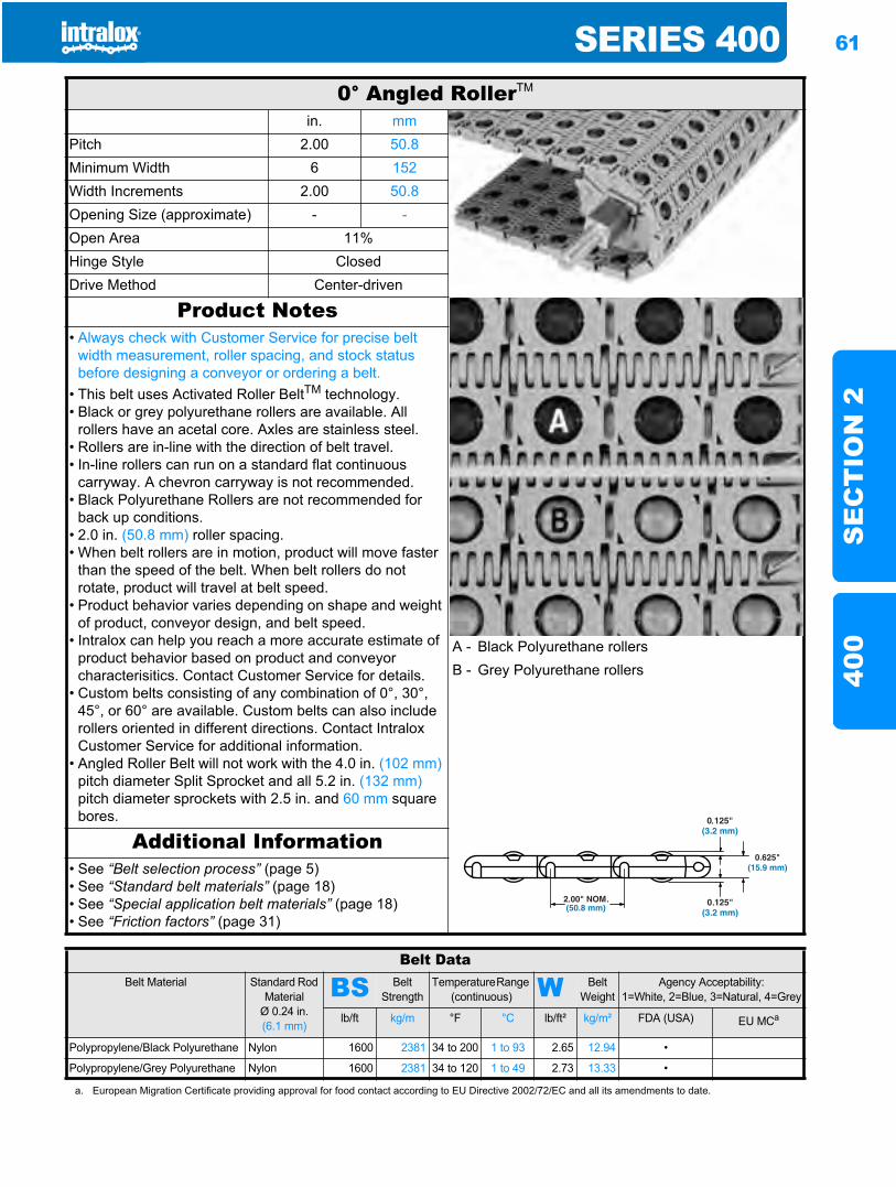
SERIES 400 61
SE
CT
ION
240
0
0° Angled RollerTM
in. mmPitch 2.00 50.8Minimum Width 6 152Width Increments 2.00 50.8Opening Size (approximate) - -Open Area 11%Hinge Style ClosedDrive Method Center-driven
Product Notes• Always check with Customer Service for precise belt
width measurement, roller spacing, and stock status before designing a conveyor or ordering a belt.
• This belt uses Activated Roller BeltTM technology.• Black or grey polyurethane rollers are available. All
rollers have an acetal core. Axles are stainless steel.• Rollers are in-line with the direction of belt travel.• In-line rollers can run on a standard flat continuous
carryway. A chevron carryway is not recommended.• Black Polyurethane Rollers are not recommended for
back up conditions.• 2.0 in. (50.8 mm) roller spacing.• When belt rollers are in motion, product will move faster
than the speed of the belt. When belt rollers do not rotate, product will travel at belt speed.
• Product behavior varies depending on shape and weight of product, conveyor design, and belt speed.
• Intralox can help you reach a more accurate estimate of product behavior based on product and conveyor characterisitics. Contact Customer Service for details.
• Custom belts consisting of any combination of 0°, 30°, 45°, or 60° are available. Custom belts can also include rollers oriented in different directions. Contact Intralox Customer Service for additional information.
• Angled Roller Belt will not work with the 4.0 in. (102 mm)pitch diameter Split Sprocket and all 5.2 in. (132 mm)pitch diameter sprockets with 2.5 in. and 60 mm square bores.
A - Black Polyurethane rollersB - Grey Polyurethane rollers
Additional Information• See “Belt selection process” (page 5)• See “Standard belt materials” (page 18)• See “Special application belt materials” (page 18)• See “Friction factors” (page 31)
Belt DataBelt Material Standard Rod
MaterialØ 0.24 in. (6.1 mm)
BS Belt Strength
Temperature Range (continuous) W Belt
WeightAgency Acceptability:
1=White, 2=Blue, 3=Natural, 4=Grey
lb/ft kg/m °F °C lb/ft² kg/m² FDA (USA) EU MCa
Polypropylene/Black Polyurethane Nylon 1600 2381 34 to 200 1 to 93 2.65 12.94 •
Polypropylene/Grey Polyurethane Nylon 1600 2381 34 to 120 1 to 49 2.73 13.33 •
a. European Migration Certificate providing approval for food contact according to EU Directive 2002/72/EC and all its amendments to date.
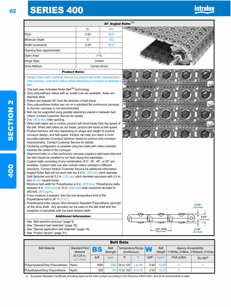
62 SERIES 400S
EC
TIO
N 2
400
30° Angled RollerTM
in. mm
Pitch 2.00 50.8
Minimum Width 6 152
Width Increments 2.00 50.8
Opening Size (approximate) - -
Open Area 11%
Hinge Style Closed
Drive Method Center-driven
Product Notes
• Always check with Customer Service for precise belt width measurement, roller spacing, and stock status before designing a conveyor or ordering a belt.
• This belt uses Activated Roller BeltTM technology.• Grey polyurethane rollers with an acetal core are available. Axles are
stainless steel.• Rollers are skewed 30° from the direction of belt travel.• Grey polyurethane rollers can run on a standard flat continuous carryway.
A chevron carryway is not recommended.• Belt can be supported using parallel wearstrips placed in between belt
rollers. Contact Customer Service for details.• 2 in. (50.8 mm) roller spacing.• When belt rollers are in motion, product will move faster than the speed of
the belt. When belt rollers do not rotate, product will travel at belt speed.• Product behavior will vary depending on shape and weight of product,
conveyor design, and belt speed. Intralox can help you reach a more accurate estimate of product behavior based on product and conveyor characteristics. Contact Customer Service for details.
• Centering configuration is possible using two belts with rollers oriented towards the center of the conveyor.
• Alignment belts on a flat continuous carryway require a side wear strip and the belt should be installed to run flush along this wearstrips.
• Custom belts consisting of any combination of 0°, 30°, 45°, or 60° are available. Custom belts can also include rollers oriented in different directions. Contact Intralox Customer Service for additional information.
• Angled Roller Belt will not work with the 4.0 in. (102 mm) pitch diameter Split Sprocket and all 5.2 in. (132 mm) pitch diameter sprockets with 2.5 in. and 60 mm square bores.
• Minimum belt width for Polyethylene is 8 in. (203 mm). Polyethylene belts between 8 in. (203 mm) to 10 in. (254 mm) wide should be de-rated to 450 lb/ft. (670 kg/m).
• If any moisture is present, then the low temperature limit of the Polyethylene belt is 34° F (1° C).
• Polyethylene belts require Ultra Abrasion Resistant Polyurethane sprocket on the drive shaft. Any sprocket can be used on the idle shaft with the exception of sprockets with low back tension teeth.
Additional Information
• See “Belt selection process” (page 5)• See “Standard belt materials” (page 18)• See “Special application belt materials” (page 18)• See “Friction factors” (page 31)
Belt DataBelt Material Standard Rod
MaterialØ 0.24 in. (6.1 mm)
BS Belt Strength
Temperature Range (continuous) W Belt
WeightAgency Acceptability:
1=White, 2=Blue, 3=Natural, 4=Grey
lb/ft kg/m °F °C lb/ft² kg/m² FDA (USA) EU MCa
Polypropylene/Grey Polyurethane Nylon 1600 2381 34 to 120 1 to 49 2.64 12.89 • •
Polyethylene/Grey Polyurethane Nylon 500 744 17 to 150 -8 to 65 2.93 14.31 •
a. European Migration Certificate providing approval for food contact according to EU Directive 2002/72/EC and all its amendments to date.
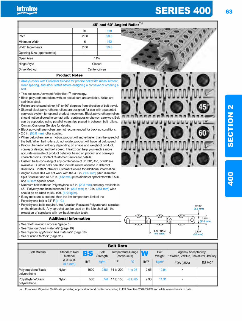
SERIES 400 63
SE
CT
ION
240
0
45° and 60° Angled RollerTM
in. mm
Pitch 2.00 50.8
Minimum Width 6 152
Width Increments 2.00 50.8
Opening Size (approximate) - -
Open Area 11%
Hinge Style Closed
Drive Method Center-driven
Product Notes• Always check with Customer Service for precise belt width measurement,
roller spacing, and stock status before designing a conveyor or ordering a belt.
• This belt uses Activated Roller BeltTM technology.• Black polyurethane rollers with an acetal core are available. Axles are
stainless steel.• Rollers are skewed either 45° or 60° degrees from direction of belt travel.• Skewed black polyurethane rollers are designed for use with a patented
carryway system for optimal product movement. Black polyurethane rollers should not be allowed to contact a flat continuous or chevron carryway. Belt can be supported using parallel wearstrips placed in between belt rollers. Contact Customer Service for details.
• Black polyurethane rollers are not recommended for back up conditions.• 2.0 in. (50.8 mm) roller spacing.• When belt rollers are in motion, product will move faster than the speed of
the belt. When belt rollers do not rotate, product will travel at belt speed.• Product behavior will vary depending on shape and weight of product,
conveyor design, and belt speed. Intralox can help you reach a more accurate estimate of product behavior based on product and conveyor characterisitics. Contact Customer Service for details.
• Custom belts consisting of any combination of 0°, 30°, 45°, or 60° are available. Custom belts can also include rollers oriented in different directions. Contact Intralox Customer Service for additional information.
• Angled Roller Belt will not work with the 4.0 in. (102 mm) pitch diameter Split Sprocket and all 5.2 in. (132 mm) pitch diameter sprockets with 2.5 in. and 60 mm square bores.
• Minimum belt width for Polyethylene is 8 in. (203 mm) and only available in 45°. Polyethylene belts between 8 in. (203 mm) to 10 in. (254 mm) wide should be de-rated to 450 lb/ft. (670 kg/m).
• If any moisture is present, then the low temperature limit of the Polyethylene belt is 34° F (1° C).
• Polyethylene belts require Ultra Abrasion Resistant Polyurethane sprocket on the drive shaft. Any sprocket can be used on the idle shaft with the exception of sprockets with low back tension teeth.
Additional Information• See “Belt selection process” (page 5)• See “Standard belt materials” (page 18)• See “Special application belt materials” (page 18)• See “Friction factors” (page 31)
Belt DataBelt Material Standard Rod
MaterialØ 0.24 in. (6.1 mm)
BS Belt Strength
Temperature Range (continuous) W Belt
WeightAgency Acceptability:
1=White, 2=Blue, 3=Natural, 4=Grey
lb/ft kg/m °F °C lb/ft² kg/m² FDA (USA) EU MCa
Polypropylene/Black polyurethane
Nylon 1600 2381 34 to 200 1 to 93 2.65 12.94 •
Polyethylene/Black polyurethane
Nylon 500 744 17 to 150 -8 to 65 2.93 14.31 •
a. European Migration Certificate providing approval for food contact according to EU Directive 2002/72/EC and all its amendments to date.
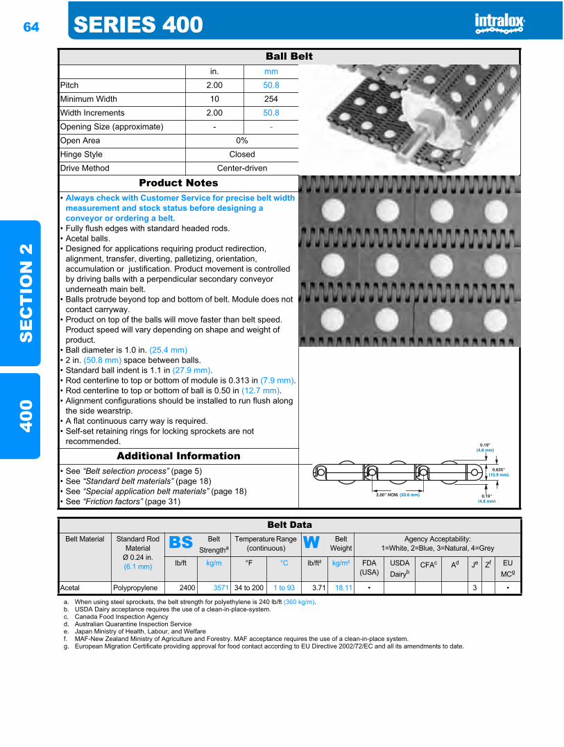
64 SERIES 400S
EC
TIO
N 2
400
Ball Beltin. mm
Pitch 2.00 50.8
Minimum Width 10 254
Width Increments 2.00 50.8
Opening Size (approximate) - -
Open Area 0%
Hinge Style Closed
Drive Method Center-driven
Product Notes• Always check with Customer Service for precise belt width
measurement and stock status before designing a conveyor or ordering a belt.
• Fully flush edges with standard headed rods.• Acetal balls.• Designed for applications requiring product redirection,
alignment, transfer, diverting, palletizing, orientation, accumulation or justification. Product movement is controlled by driving balls with a perpendicular secondary conveyor underneath main belt.
• Balls protrude beyond top and bottom of belt. Module does not contact carryway.
• Product on top of the balls will move faster than belt speed. Product speed will vary depending on shape and weight of product.
• Ball diameter is 1.0 in. (25.4 mm)• 2 in. (50.8 mm) space between balls.• Standard ball indent is 1.1 in (27.9 mm).• Rod centerline to top or bottom of module is 0.313 in (7.9 mm).• Rod centerline to top or bottom of ball is 0.50 in (12.7 mm).• Alignment configurations should be installed to run flush along
the side wearstrip.• A flat continuous carry way is required.• Self-set retaining rings for locking sprockets are not
recommended.
Additional Information• See “Belt selection process” (page 5)• See “Standard belt materials” (page 18)• See “Special application belt materials” (page 18)• See “Friction factors” (page 31)
Belt DataBelt Material Standard Rod
MaterialØ 0.24 in. (6.1 mm)
BS Belt Strengtha
Temperature Range (continuous) W Belt
WeightAgency Acceptability:
1=White, 2=Blue, 3=Natural, 4=Grey
lb/ft kg/m °F °C lb/ft² kg/m² FDA (USA)
USDADairyb
CFAc Ad Je Zf EUMCg
Acetal Polypropylene 2400 3571 34 to 200 1 to 93 3.71 18.11 • 3 •
a. When using steel sprockets, the belt strength for polyethylene is 240 lb/ft (360 kg/m).b. USDA Dairy acceptance requires the use of a clean-in-place-system.c. Canada Food Inspection Agencyd. Australian Quarantine Inspection Servicee. Japan Ministry of Health, Labour, and Welfaref. MAF-New Zealand Ministry of Agriculture and Forestry. MAF acceptance requires the use of a clean-in-place system.g. European Migration Certificate providing approval for food contact according to EU Directive 2002/72/EC and all its amendments to date.
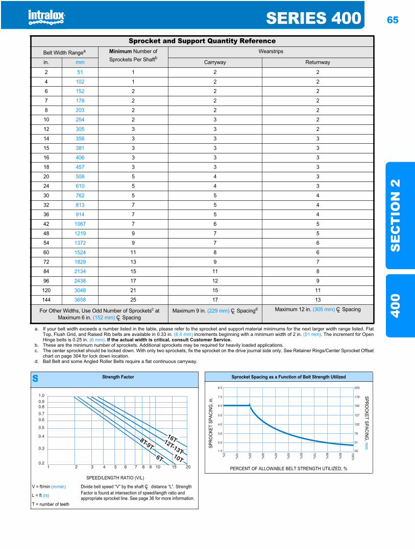
SERIES 400 65
SE
CT
ION
240
0
Sprocket and Support Quantity ReferenceBelt Width Rangea Minimum Number of
Sprockets Per ShaftbWearstrips
in. mm Carryway Returnway
2 51 1 2 2
4 102 1 2 2
6 152 2 2 2
7 178 2 2 2
8 203 2 2 2
10 254 2 3 2
12 305 3 3 2
14 356 3 3 3
15 381 3 3 3
16 406 3 3 3
18 457 3 3 3
20 508 5 4 3
24 610 5 4 3
30 762 5 5 4
32 813 7 5 4
36 914 7 5 4
42 1067 7 6 5
48 1219 9 7 5
54 1372 9 7 6
60 1524 11 8 6
72 1829 13 9 7
84 2134 15 11 8
96 2438 17 12 9
120 3048 21 15 11
144 3658 25 17 13
For Other Widths, Use Odd Number of Sprocketsc at Maximum 6 in. (152 mm) CL Spacing
Maximum 9 in. (229 mm) CL Spacingd Maximum 12 in. (305 mm) CL Spacing
a. If your belt width exceeds a number listed in the table, please refer to the sprocket and support material minimums for the next larger width range listed. FlatTop, Flush Grid, and Raised Rib belts are available in 0.33 in. (8.4 mm) increments beginning with a minimum width of 2 in. (51 mm). The increment for OpenHinge belts is 0.25 in. (6 mm). If the actual width is critical, consult Customer Service.
b. These are the minimum number of sprockets. Additional sprockets may be required for heavily loaded applications.c. The center sprocket should be locked down. With only two sprockets, fix the sprocket on the drive journal side only. See Retainer Rings/Center Sprocket Offset
chart on page 304 for lock down location.d. Ball Belt and some Angled Roller Belts require a flat continuous carryway.
S Strength Factor
SPEED/LENGTH RATIO (V/L)
V = ft/min (m/min) Divide belt speed “V” by the shaft CL distance “L”. Strength Factor is found at intersection of speed/length ratio and appropriate sprocket line. See page 36 for more information.L = ft (m)
T = number of teeth
Sprocket Spacing as a Function of Belt Strength Utilized
SPRO
CKET
SPA
CING
, in.
SPROCKET SPACING
, mm
PERCENT OF ALLOWABLE BELT STRENGTH UTILIZED, %
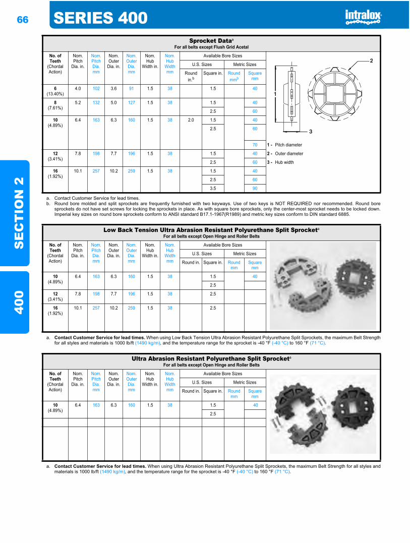
66 SERIES 400S
EC
TIO
N 2
400
Sprocket Dataa
For all belts except Flush Grid Acetal
No. of Teeth
(Chordal Action)
Nom. Pitch
Dia. in.
Nom. Pitch Dia. mm
Nom. Outer
Dia. in.
Nom. Outer Dia. mm
Nom. Hub
Width in.
Nom. Hub
Width mm
Available Bore Sizes
U.S. Sizes Metric Sizes
Round in.b
Square in. Round mmb
Square mm
6(13.40%)
4.0 102 3.6 91 1.5 38 1.5 40
8(7.61%)
5.2 132 5.0 127 1.5 38 1.5 40
2.5 60
10(4.89%)
6.4 163 6.3 160 1.5 38 2.0 1.5 40
2.5 60
70 1 - Pitch diameter
12(3.41%)
7.8 198 7.7 196 1.5 38 1.5 40 2 - Outer diameter
2.5 60 3 - Hub width
16(1.92%)
10.1 257 10.2 259 1.5 38 1.5 40
2.5 60
3.5 90
a. Contact Customer Service for lead times.b. Round bore molded and split sprockets are frequently furnished with two keyways. Use of two keys is NOT REQUIRED nor recommended. Round bore
sprockets do not have set screws for locking the sprockets in place. As with square bore sprockets, only the center-most sprocket needs to be locked down.Imperial key sizes on round bore sprockets conform to ANSI standard B17.1-1967(R1989) and metric key sizes conform to DIN standard 6885.
Low Back Tension Ultra Abrasion Resistant Polyurethane Split Sprocketa
For all belts except Open Hinge and Roller Belts
No. of Teeth
(Chordal Action)
Nom. Pitch
Dia. in.
Nom. Pitch Dia. mm
Nom. Outer
Dia. in.
Nom. Outer Dia. mm
Nom. Hub
Width in.
Nom. Hub
Width mm
Available Bore Sizes
U.S. Sizes Metric Sizes
Round in. Square in. Round mm
Square mm
10(4.89%)
6.4 163 6.3 160 1.5 38 1.5 40
2.5
12(3.41%)
7.8 198 7.7 196 1.5 38 2.5
16(1.92%)
10.1 257 10.2 259 1.5 38 2.5
a. Contact Customer Service for lead times. When using Low Back Tension Ultra Abrasion Resistant Polyurethane Split Sprockets, the maximum Belt Strengthfor all styles and materials is 1000 lb/ft (1490 kg/m), and the temperature range for the sprocket is -40 °F (-40 °C) to 160 °F (71 °C).
Ultra Abrasion Resistant Polyurethane Split Sprocketa
For all belts except Open Hinge and Roller Belts
No. of Teeth
(Chordal Action)
Nom. Pitch
Dia. in.
Nom. Pitch Dia. mm
Nom. Outer
Dia. in.
Nom. Outer Dia. mm
Nom. Hub
Width in.
Nom. Hub
Width mm
Available Bore Sizes
U.S. Sizes Metric Sizes
Round in. Square in. Round mm
Square mm
10(4.89%)
6.4 163 6.3 160 1.5 38 1.5 40
2.5
a. Contact Customer Service for lead times. When using Ultra Abrasion Resistant Polyurethane Split Sprockets, the maximum Belt Strength for all styles andmaterials is 1000 lb/ft (1490 kg/m), and the temperature range for the sprocket is -40 °F (-40 °C) to 160 °F (71 °C).
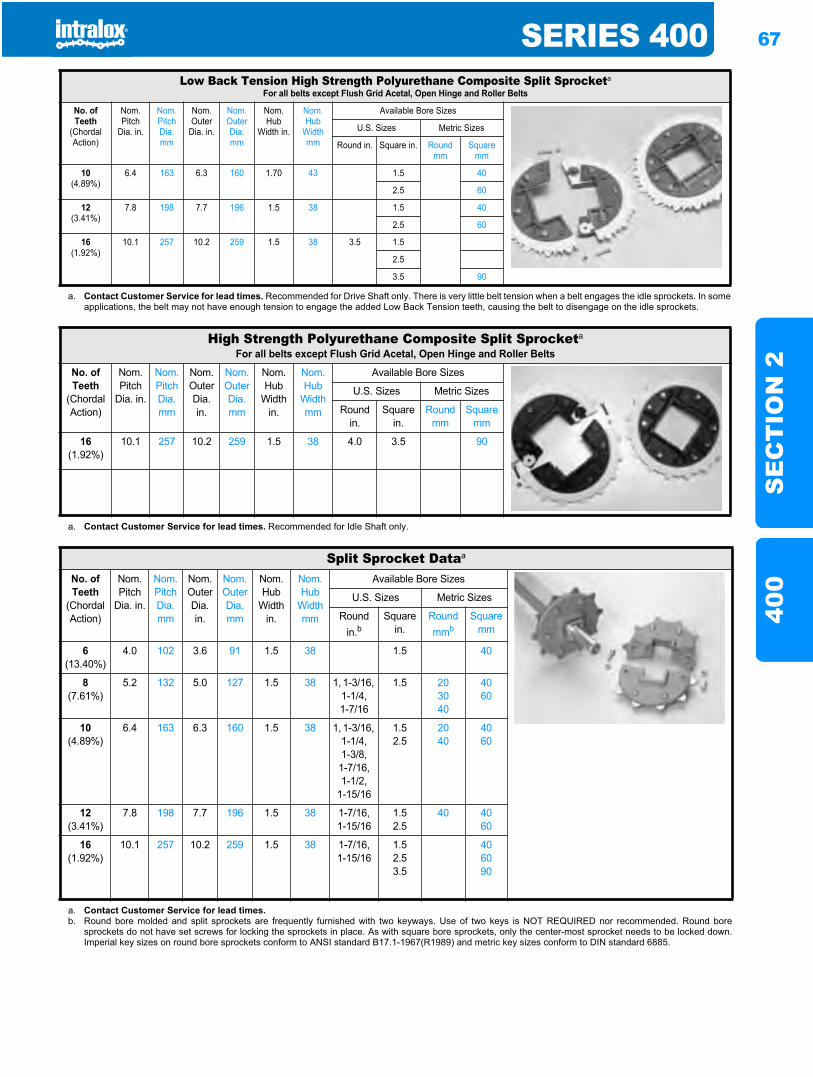
SERIES 400 67
SE
CT
ION
240
0
Low Back Tension High Strength Polyurethane Composite Split Sprocketa
For all belts except Flush Grid Acetal, Open Hinge and Roller Belts
No. of Teeth
(Chordal Action)
Nom. Pitch
Dia. in.
Nom. Pitch Dia. mm
Nom. Outer
Dia. in.
Nom. Outer Dia. mm
Nom. Hub
Width in.
Nom. Hub
Width mm
Available Bore Sizes
U.S. Sizes Metric Sizes
Round in. Square in. Round mm
Square mm
10(4.89%)
6.4 163 6.3 160 1.70 43 1.5 40
2.5 60
12(3.41%)
7.8 198 7.7 196 1.5 38 1.5 40
2.5 60
16(1.92%)
10.1 257 10.2 259 1.5 38 3.5 1.5
2.5
3.5 90
a. Contact Customer Service for lead times. Recommended for Drive Shaft only. There is very little belt tension when a belt engages the idle sprockets. In someapplications, the belt may not have enough tension to engage the added Low Back Tension teeth, causing the belt to disengage on the idle sprockets.
High Strength Polyurethane Composite Split Sprocketa
For all belts except Flush Grid Acetal, Open Hinge and Roller Belts
No. of Teeth
(Chordal Action)
Nom. Pitch
Dia. in.
Nom. Pitch Dia. mm
Nom. Outer Dia.in.
Nom. OuterDia. mm
Nom. Hub
Width in.
Nom. Hub
Width mm
Available Bore Sizes
U.S. Sizes Metric Sizes
Round in.
Square in.
Round mm
Square mm
16(1.92%)
10.1 257 10.2 259 1.5 38 4.0 3.5 90
a. Contact Customer Service for lead times. Recommended for Idle Shaft only.
Split Sprocket Dataa
No. of Teeth
(Chordal Action)
Nom. Pitch
Dia. in.
Nom. Pitch Dia.mm
Nom. Outer Dia. in.
Nom. Outer Dia. mm
Nom. Hub
Width in.
Nom. Hub
Width mm
Available Bore Sizes
U.S. Sizes Metric Sizes
Round in.b
Square in.
Round mmb
Square mm
6(13.40%)
4.0 102 3.6 91 1.5 38 1.5 40
8(7.61%)
5.2 132 5.0 127 1.5 38 1, 1-3/16, 1-1/4,1-7/16
1.5 203040
4060
10(4.89%)
6.4 163 6.3 160 1.5 38 1, 1-3/16, 1-1/4,1-3/8,1-7/16,1-1/2,
1-15/16
1.52.5
2040
4060
12(3.41%)
7.8 198 7.7 196 1.5 38 1-7/16,1-15/16
1.52.5
40 4060
16(1.92%)
10.1 257 10.2 259 1.5 38 1-7/16,1-15/16
1.52.53.5
406090
a. Contact Customer Service for lead times.b. Round bore molded and split sprockets are frequently furnished with two keyways. Use of two keys is NOT REQUIRED nor recommended. Round bore
sprockets do not have set screws for locking the sprockets in place. As with square bore sprockets, only the center-most sprocket needs to be locked down.Imperial key sizes on round bore sprockets conform to ANSI standard B17.1-1967(R1989) and metric key sizes conform to DIN standard 6885.
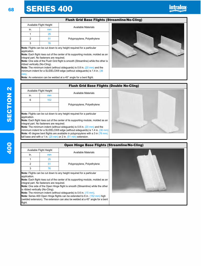
68 SERIES 400S
EC
TIO
N 2
400
Flush Grid Base Flights (Streamline/No-Cling)Available Flight Height
Available Materialsin. mm
1 25
Polypropylene, Polyethylene2 51
3 76
Note: Flights can be cut down to any height required for a particular application.Note: Each flight rises out of the center of its supporting module, molded as an integral part. No fasteners are required.Note: One side of the Flush Grid flight is smooth (Streamline) while the other is ribbed vertically (No-Cling).Note: The minimum indent (without sideguards) is 0.8 in. (20 mm) and the minimum indent for a SLIDELOX® edge (without sideguards) is 1.4 in. (36 mm).Note: An extension can be welded at a 45° angle for a bent flight.
Flush Grid Base Flights (Double No-Cling)Available Flight Height
Available Materialsin. mm
6 152
Polypropylene, Polyethylene
Note: Flights can be cut down to any height required for a particular application.Note: Each flight rises out of the center of its supporting module, molded as an integral part. No fasteners are required.Note: The minimum indent (without sideguards) is 0.8 in. (20 mm) and the minimum indent for a SLIDELOX® edge (without sideguards) is 1.4 in. (36 mm)Note: 45 degree bent flights are available in polypropylene with a 3 in (76 mm)tall base and with a 1 in. (25 mm) or 2 in. (51 mm) extension.
Open Hinge Base Flights (Streamline/No-Cling)Available Flight Height
Available Materialsin. mm
1 25
Polypropylene, Polyethylene2 51
3 76
Note: Flights can be cut down to any height required for a particular application.Note: Each flight rises out of the center of its supporting module, molded as an integral part. No fasteners are required.Note: One side of the Open Hinge flight is smooth (Streamline) while the other is ribbed vertically (No-Cling).Note: The minimum indent (without sideguards) is 0.6 in. (15 mm).Note: Series 400 Open Hinge flights can be extended to 6 in. (152 mm) high (welded extension). The extension can also be welded at a 45° angle for a bent flight.
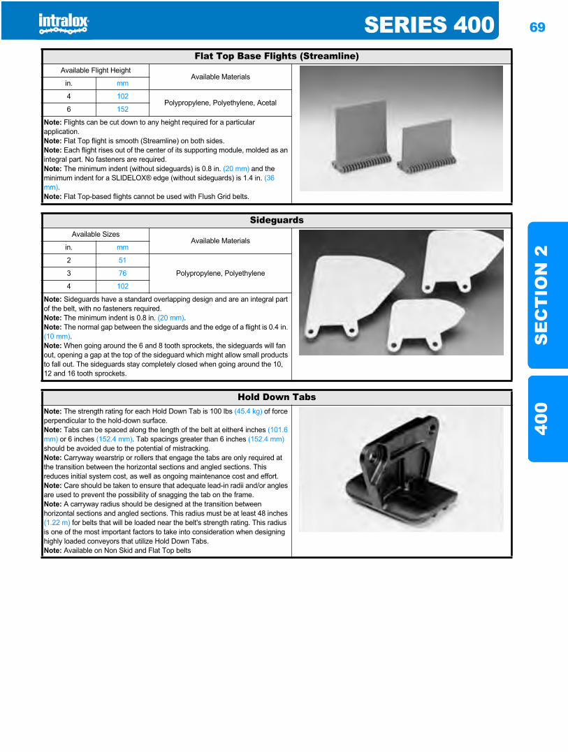
SERIES 400 69
SE
CT
ION
240
0
Flat Top Base Flights (Streamline)Available Flight Height
Available Materialsin. mm
4 102Polypropylene, Polyethylene, Acetal
6 152
Note: Flights can be cut down to any height required for a particular application.Note: Flat Top flight is smooth (Streamline) on both sides.Note: Each flight rises out of the center of its supporting module, molded as an integral part. No fasteners are required.Note: The minimum indent (without sideguards) is 0.8 in. (20 mm) and the minimum indent for a SLIDELOX® edge (without sideguards) is 1.4 in. (36 mm).Note: Flat Top-based flights cannot be used with Flush Grid belts.
SideguardsAvailable Sizes
Available Materialsin. mm
2 51
Polypropylene, Polyethylene3 76
4 102
Note: Sideguards have a standard overlapping design and are an integral part of the belt, with no fasteners required.Note: The minimum indent is 0.8 in. (20 mm).Note: The normal gap between the sideguards and the edge of a flight is 0.4 in. (10 mm).Note: When going around the 6 and 8 tooth sprockets, the sideguards will fan out, opening a gap at the top of the sideguard which might allow small products to fall out. The sideguards stay completely closed when going around the 10, 12 and 16 tooth sprockets.
Hold Down TabsNote: The strength rating for each Hold Down Tab is 100 lbs (45.4 kg) of force perpendicular to the hold-down surface.Note: Tabs can be spaced along the length of the belt at either4 inches (101.6 mm) or 6 inches (152.4 mm). Tab spacings greater than 6 inches (152.4 mm)should be avoided due to the potential of mistracking.Note: Carryway wearstrip or rollers that engage the tabs are only required at the transition between the horizontal sections and angled sections. This reduces initial system cost, as well as ongoing maintenance cost and effort.Note: Care should be taken to ensure that adequate lead-in radii and/or angles are used to prevent the possibility of snagging the tab on the frame.Note: A carryway radius should be designed at the transition between horizontal sections and angled sections. This radius must be at least 48 inches (1.22 m) for belts that will be loaded near the belt's strength rating. This radius is one of the most important factors to take into consideration when designing highly loaded conveyors that utilize Hold Down Tabs.Note: Available on Non Skid and Flat Top belts
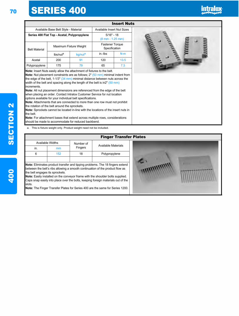
70 SERIES 400S
EC
TIO
N 2
400
Insert NutsAvailable Base Belt Style - Material Available Insert Nut Sizes
Series 400 Flat Top - Acetal, Polypropylene 5/16" - 18(8 mm - 1.25 mm)
Belt MaterialMaximum Fixture Weight Fastener Torque
Specification
lbs/nuta kg/nuta in.-lbs N-m
Acetal 200 91 120 13.5
Polypropylene 175 79 65 7.3
Note: Insert Nuts easily allow the attachment of fixtures to the belt.Note: Nut placement constraints are as follows; 2" (50 mm) minimal indent from the edge of the belt, 1-1/3" (34 mm) minimal distance between nuts across the width of the belt and spacing along the length of the belt is in2" (50 mm)increments.Note: All nut placement dimensions are referenced from the edge of the belt when placing an order. Contact Intralox Customer Service for nut location options available for your individual belt specifications.Note: Attachments that are connected to more than one row must not prohibit the rotation of the belt around the sprockets.Note: Sprockets cannot be located in-line with the locations of the insert nuts in the belt.Note: For attachment bases that extend across multiple rows, considerations should be made to accommodate for reduced backbend.
a. This is fixture weight only. Product weight need not be included.
Finger Transfer PlatesAvailable Widths Number of
Fingers Available Materialsin. mm
6 152 18 Polypropylene
Note: Eliminates product transfer and tipping problems. The 18 fingers extend between the belt’s ribs allowing a smooth continuation of the product flow as the belt engages its sprockets. Note: Easily installed on the conveyor frame with the shoulder bolts supplied. Caps snap easily into place over the bolts, keeping foreign materials out of the slots.Note: The Finger Transfer Plates for Series 400 are the same for Series 1200.
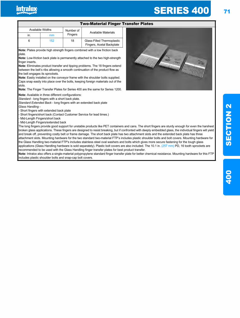
SERIES 400 71
SE
CT
ION
240
0
Two-Material Finger Transfer PlatesAvailable Widths Number of
Fingers Available Materialsin. mm
6 152 18 Glass-Filled Thermoplastic Fingers, Acetal Backplate
Note: Plates provide high strength fingers combined with a low friction back plate.Note: Low-friction back plate is permanently attached to the two high-strength finger inserts.Note: Eliminates product transfer and tipping problems. The 18 fingers extend between the belt’s ribs allowing a smooth continuation of the product flow as the belt engages its sprockets.Note: Easily installed on the conveyor frame with the shoulder bolts supplied. Caps snap easily into place over the bolts, keeping foreign materials out of the slots.Note: The Finger Transfer Plates for Series 400 are the same for Series 1200.
Note: Available in three different configurations:Standard - long fingers with a short back plate.Standard Extended Back - long fingers with an extended back plateGlass Handling -- Short fingers with extended back plate- Short fingers/short back (Contact Customer Service for lead times.) - Mid-Length Fingers/short back- Mid-Length Fingers/extended backThe long fingers provide good support for unstable products like PET containers and cans. The short fingers are sturdy enough for even the harshest broken glass applications. These fingers are designed to resist breaking, but if confronted with deeply embedded glass, the individual fingers will yield and break off, preventing costly belt or frame damage. The short back plate has two attachment slots and the extended back plate has three attachment slots. Mounting hardware for the two standard two-material FTP’s includes plastic shoulder bolts and bolt covers. Mounting hardware for the Glass Handling two-material FTP's includes stainless steel oval washers and bolts which gives more secure fastening for the tough glass applications (Glass Handling hardware is sold separately). Plastic bolt covers are also included. The 10.1 in. (257 mm) PD, 16 tooth sprockets are recommended to be used with the Glass Handling finger transfer plates for best product transfer.Note: Intralox also offers a single-material polypropylene standard finger transfer plate for better chemical resistance. Mounting hardware for this FTP includes plastic shoulder bolts and snap-cap bolt covers.
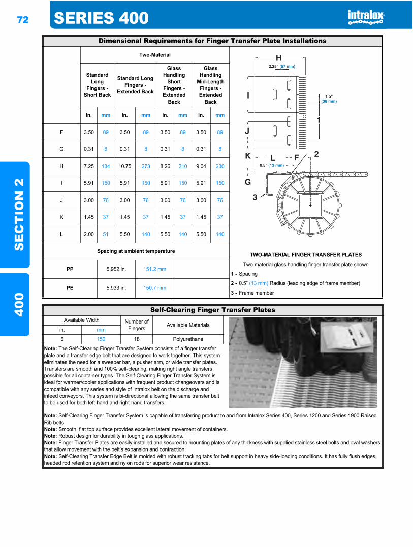
72 SERIES 400S
EC
TIO
N 2
400
Dimensional Requirements for Finger Transfer Plate Installations
Two-Material
Standard Long
Fingers - Short Back
Standard Long Fingers -
Extended Back
Glass Handling
Short Fingers - Extended
Back
Glass Handling
Mid-Length Fingers - Extended
Back
in. mm in. mm in. mm in. mm
F 3.50 89 3.50 89 3.50 89 3.50 89
G 0.31 8 0.31 8 0.31 8 0.31 8
H 7.25 184 10.75 273 8.26 210 9.04 230
I 5.91 150 5.91 150 5.91 150 5.91 150
J 3.00 76 3.00 76 3.00 76 3.00 76
K 1.45 37 1.45 37 1.45 37 1.45 37
L 2.00 51 5.50 140 5.50 140 5.50 140
Spacing at ambient temperatureTWO-MATERIAL FINGER TRANSFER PLATES
PP 5.952 in. 151.2 mmTwo-material glass handling finger transfer plate shown
1 - Spacing
PE 5.933 in. 150.7 mm2 - 0.5” (13 mm) Radius (leading edge of frame member)
3 - Frame member
Self-Clearing Finger Transfer PlatesAvailable Width Number of
Fingers Available Materialsin. mm
6 152 18 Polyurethane
Note: The Self-Clearing Finger Transfer System consists of a finger transfer plate and a transfer edge belt that are designed to work together. This system eliminates the need for a sweeper bar, a pusher arm, or wide transfer plates. Transfers are smooth and 100% self-clearing, making right angle transfers possible for all container types. The Self-Clearing Finger Transfer System is ideal for warmer/cooler applications with frequent product changeovers and is compatible with any series and style of Intralox belt on the discharge and infeed conveyors. This system is bi-directional allowing the same transfer belt to be used for both left-hand and right-hand transfers.
Note: Self-Clearing Finger Transfer System is capable of transferring product to and from Intralox Series 400, Series 1200 and Series 1900 Raised Rib belts.Note: Smooth, flat top surface provides excellent lateral movement of containers.Note: Robust design for durability in tough glass applications.Note: Finger Transfer Plates are easily installed and secured to mounting plates of any thickness with supplied stainless steel bolts and oval washers that allow movement with the belt’s expansion and contraction.Note: Self-Clearing Transfer Edge Belt is molded with robust tracking tabs for belt support in heavy side-loading conditions. It has fully flush edges, headed rod retention system and nylon rods for superior wear resistance.
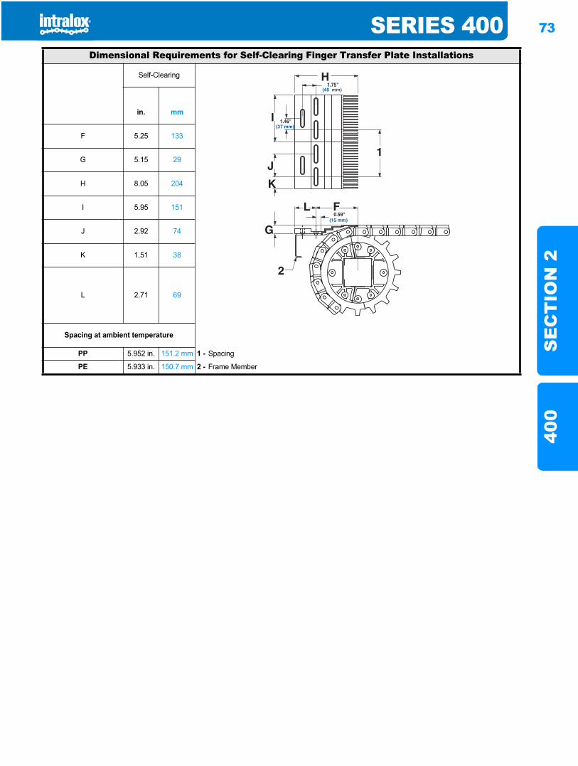
SERIES 400 73
SE
CT
ION
240
0
Dimensional Requirements for Self-Clearing Finger Transfer Plate Installations
Self-Clearing
in. mm
F 5.25 133
G 5.15 29
H 8.05 204
I 5.95 151
J 2.92 74
K 1.51 38
L 2.71 69
Spacing at ambient temperature
PP 5.952 in. 151.2 mm 1 - Spacing
PE 5.933 in. 150.7 mm 2 - Frame Member
1.75"(45 mm)
0.59"(15 mm)
1.46"(37 mm)
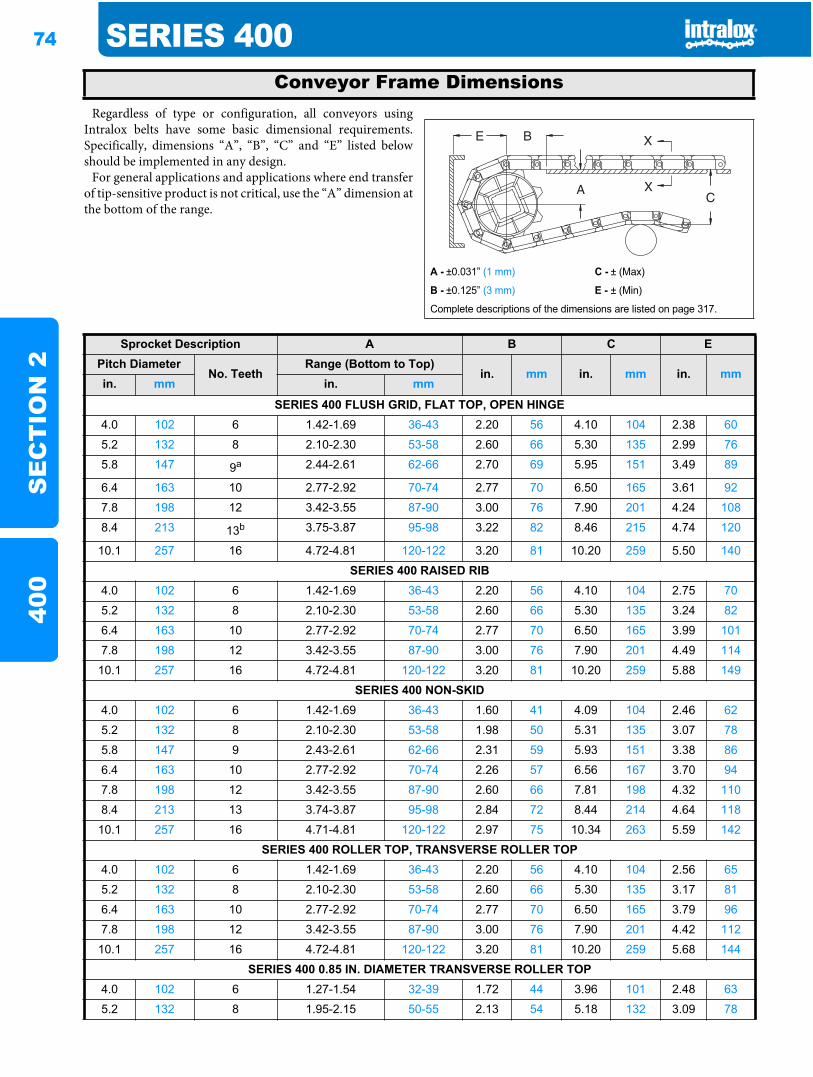
74 SERIES 400S
EC
TIO
N 2
400
Regardless of type or configuration, all conveyors usingIntralox belts have some basic dimensional requirements.Specifically, dimensions “A”, “B”, “C” and “E” listed belowshould be implemented in any design.
For general applications and applications where end transferof tip-sensitive product is not critical, use the “A” dimension atthe bottom of the range.
Conveyor Frame Dimensions
A - ±0.031” (1 mm) C - ± (Max)
B - ±0.125” (3 mm) E - ± (Min)
Complete descriptions of the dimensions are listed on page 317.
Sprocket Description A B C EPitch Diameter
No. TeethRange (Bottom to Top)
in. mm in. mm in. mmin. mm in. mm
SERIES 400 FLUSH GRID, FLAT TOP, OPEN HINGE4.0 102 6 1.42-1.69 36-43 2.20 56 4.10 104 2.38 60
5.2 132 8 2.10-2.30 53-58 2.60 66 5.30 135 2.99 76
5.8 147 9a 2.44-2.61 62-66 2.70 69 5.95 151 3.49 89
6.4 163 10 2.77-2.92 70-74 2.77 70 6.50 165 3.61 92
7.8 198 12 3.42-3.55 87-90 3.00 76 7.90 201 4.24 108
8.4 213 13b 3.75-3.87 95-98 3.22 82 8.46 215 4.74 120
10.1 257 16 4.72-4.81 120-122 3.20 81 10.20 259 5.50 140
SERIES 400 RAISED RIB4.0 102 6 1.42-1.69 36-43 2.20 56 4.10 104 2.75 70
5.2 132 8 2.10-2.30 53-58 2.60 66 5.30 135 3.24 82
6.4 163 10 2.77-2.92 70-74 2.77 70 6.50 165 3.99 101
7.8 198 12 3.42-3.55 87-90 3.00 76 7.90 201 4.49 114
10.1 257 16 4.72-4.81 120-122 3.20 81 10.20 259 5.88 149
SERIES 400 NON-SKID4.0 102 6 1.42-1.69 36-43 1.60 41 4.09 104 2.46 62
5.2 132 8 2.10-2.30 53-58 1.98 50 5.31 135 3.07 78
5.8 147 9 2.43-2.61 62-66 2.31 59 5.93 151 3.38 86
6.4 163 10 2.77-2.92 70-74 2.26 57 6.56 167 3.70 94
7.8 198 12 3.42-3.55 87-90 2.60 66 7.81 198 4.32 110
8.4 213 13 3.74-3.87 95-98 2.84 72 8.44 214 4.64 118
10.1 257 16 4.71-4.81 120-122 2.97 75 10.34 263 5.59 142
SERIES 400 ROLLER TOP, TRANSVERSE ROLLER TOP4.0 102 6 1.42-1.69 36-43 2.20 56 4.10 104 2.56 65
5.2 132 8 2.10-2.30 53-58 2.60 66 5.30 135 3.17 81
6.4 163 10 2.77-2.92 70-74 2.77 70 6.50 165 3.79 96
7.8 198 12 3.42-3.55 87-90 3.00 76 7.90 201 4.42 112
10.1 257 16 4.72-4.81 120-122 3.20 81 10.20 259 5.68 144
SERIES 400 0.85 IN. DIAMETER TRANSVERSE ROLLER TOP4.0 102 6 1.27-1.54 32-39 1.72 44 3.96 101 2.48 63
5.2 132 8 1.95-2.15 50-55 2.13 54 5.18 132 3.09 78

SERIES 400 75
SE
CT
ION
240
0
Where there is a transfer point from a belt without fingertransfer plates to a dead plate, there should be a gap betweenthe surfaces to allow for the chordal action of the belt. As thebelt engages its sprockets, chordal action causes the modules tomove past a fixed point (the tip of the dead plate) with varyingclearances. The table below shows the minimum amount ofgap which occurs at the “low point” of the modules if the tip ofthe dead plate just comes in contact with the “high point” asthe modules pass.
In some installations it may be desirable to keep the tip of thedead plate in contact with the belt, rather than allow a gap tooccur. This can be done by hinging the mounting bracket forthe dead plate. This allows the dead plate to move as themodules pass, but results in a small oscillating motion whichmay present tippage problems for sensitive containers orproducts.
6.4 163 10 2.62-2.77 67-70 2.43 62 6.42 163 3.71 94
7.8 198 12 3.27-3.40 83-86 2.78 71 7.68 195 4.34 110
10.1 257 16 4.56-4.66 116-118 3.20 81 10.20 259 5.60 142
SERIES 400 ANGLED ROLLER (0°, 30°, 45° AND 60°)b
4.0 102 6 1.29-1.56 33-40 1.70 43 4.00 102 2.50 64
5.2 132 8 1.98-2.18 50-55 2.11 53 5.23 133 3.11 79
6.4 163 10 2.64-2.80 67-71 2.40 61 6.47 164 3.74 95
7.8 198 12 3.29-3.43 84-87 2.75 70 7.73 196 4.36 111
10.1 257 16 4.59-4.69 117-119 3.16 80 10.25 260 5.63 143
SERIES 400 BALL BELTb
4.0 102 6 1.23-1.50 31-38 1.75 44 4.00 102 2.56 65
5.2 132 8 1.91-2.11 49-54 2.16 55 5.23 133 3.18 81
6.4 163 10 2.58-2.74 65-69 2.47 63 6.47 164 3.80 96
7.8 198 12 3.23-3.36 82-85 2.82 72 7.73 196 4.43 112
10.1 257 16 4.53-4.63 115-117 3.25 82 10.25 260 5.69 144
a. Flush Grid Acetal only.b. Dimensions are established using the top of the roller as the top of the belt and the bottom of the roller as the bottom of the belt.
Sprocket Description A B C EPitch Diameter
No. TeethRange (Bottom to Top)
in. mm in. mm in. mmin. mm in. mm
Dead Plate Gap
1 - Top surface of dead plate 2 - Dead plate gap
Note: The top surface of the dead plate is typically 0.031 in. (0.8 mm)above the belt surface for product transfer onto the belt, and 0.031 in. (0.8 mm) below the belt surface for product transfer off the belt.
21
Sprocket Description GapPitch Diameter
No. Teeth in. mmin. mm4.0 102 6 0.268 6.85.2 132 8 0.200 5.15.8 147 9 (Flush Grid Acetal) 0.178 4.56.4 163 10 0.160 4.17.8 198 12 0.130 3.38.4 213 13 (Flush Grid Acetal) 0.121 3.1
10.1 257 16 0.100 2.5

76 SERIES 400S
EC
TIO
N 2
400
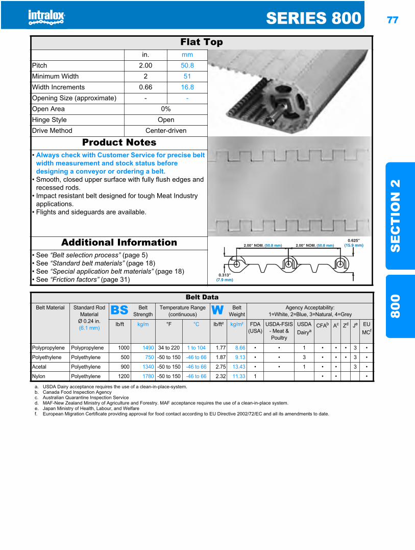
SERIES 800 77
SE
CT
ION
280
0
Series 800800
Flat Topin. mm
Pitch 2.00 50.8Minimum Width 2 51Width Increments 0.66 16.8Opening Size (approximate) - -Open Area 0%Hinge Style OpenDrive Method Center-driven
Product Notes• Always check with Customer Service for precise belt
width measurement and stock status before designing a conveyor or ordering a belt.
• Smooth, closed upper surface with fully flush edges and recessed rods.
• Impact resistant belt designed for tough Meat Industry applications.
• Flights and sideguards are available.
Additional Information• See “Belt selection process” (page 5)• See “Standard belt materials” (page 18)• See “Special application belt materials” (page 18)• See “Friction factors” (page 31)
Belt DataBelt Material Standard Rod
MaterialØ 0.24 in. (6.1 mm)
BS Belt Strength
Temperature Range (continuous) W Belt
WeightAgency Acceptability:
1=White, 2=Blue, 3=Natural, 4=Grey
lb/ft kg/m °F °C lb/ft² kg/m² FDA (USA)
USDA-FSIS - Meat & Poultry
USDADairya
CFAb Ac Zd Je EUMCf
Polypropylene Polypropylene 1000 1490 34 to 220 1 to 104 1.77 8.66 • • 1 • • • 3 •
Polyethylene Polyethylene 500 750 -50 to 150 -46 to 66 1.87 9.13 • • 3 • • • 3 •
Acetal Polyethylene 900 1340 -50 to 150 -46 to 66 2.75 13.43 • • 1 • • 3 •
Nylon Polyethylene 1200 1780 -50 to 150 -46 to 66 2.32 11.33 1 • • •
a. USDA Dairy acceptance requires the use of a clean-in-place-system.b. Canada Food Inspection Agencyc. Australian Quarantine Inspection Serviced. MAF-New Zealand Ministry of Agriculture and Forestry. MAF acceptance requires the use of a clean-in-place system.e. Japan Ministry of Health, Labour, and Welfaref. European Migration Certificate providing approval for food contact according to EU Directive 2002/72/EC and all its amendments to date.
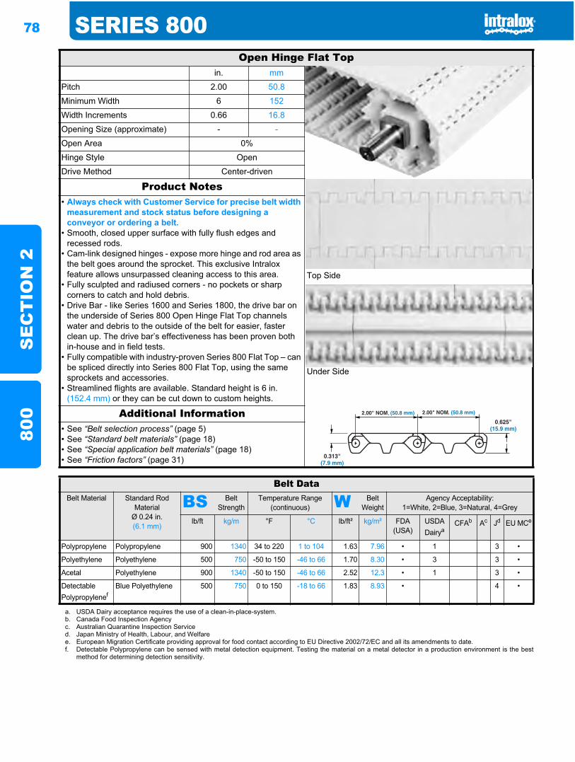
78 SERIES 800S
EC
TIO
N 2
800
Open Hinge Flat Topin. mm
Pitch 2.00 50.8
Minimum Width 6 152
Width Increments 0.66 16.8
Opening Size (approximate) - -
Open Area 0%
Hinge Style Open
Drive Method Center-driven
Product Notes
Top Side
Under Side
• Always check with Customer Service for precise belt width measurement and stock status before designing a conveyor or ordering a belt.
• Smooth, closed upper surface with fully flush edges and recessed rods.
• Cam-link designed hinges - expose more hinge and rod area as the belt goes around the sprocket. This exclusive Intralox feature allows unsurpassed cleaning access to this area.
• Fully sculpted and radiused corners - no pockets or sharp corners to catch and hold debris.
• Drive Bar - like Series 1600 and Series 1800, the drive bar on the underside of Series 800 Open Hinge Flat Top channels water and debris to the outside of the belt for easier, faster clean up. The drive bar’s effectiveness has been proven both in-house and in field tests.
• Fully compatible with industry-proven Series 800 Flat Top – can be spliced directly into Series 800 Flat Top, using the same sprockets and accessories.
• Streamlined flights are available. Standard height is 6 in. (152.4 mm) or they can be cut down to custom heights.
Additional Information• See “Belt selection process” (page 5)• See “Standard belt materials” (page 18)• See “Special application belt materials” (page 18)• See “Friction factors” (page 31)
Belt DataBelt Material Standard Rod
MaterialØ 0.24 in. (6.1 mm)
BS Belt Strength
Temperature Range (continuous) W Belt
WeightAgency Acceptability:
1=White, 2=Blue, 3=Natural, 4=Grey
lb/ft kg/m °F °C lb/ft² kg/m² FDA (USA)
USDADairya
CFAb Ac Jd EU MCe
Polypropylene Polypropylene 900 1340 34 to 220 1 to 104 1.63 7.96 • 1 3 •
Polyethylene Polyethylene 500 750 -50 to 150 -46 to 66 1.70 8.30 • 3 3 •
Acetal Polyethylene 900 1340 -50 to 150 -46 to 66 2.52 12.3 • 1 3 •
Detectable Polypropylenef
Blue Polyethylene 500 750 0 to 150 -18 to 66 1.83 8.93 • 4 •
a. USDA Dairy acceptance requires the use of a clean-in-place-system.b. Canada Food Inspection Agencyc. Australian Quarantine Inspection Serviced. Japan Ministry of Health, Labour, and Welfaree. European Migration Certificate providing approval for food contact according to EU Directive 2002/72/EC and all its amendments to date.f. Detectable Polypropylene can be sensed with metal detection equipment. Testing the material on a metal detector in a production environment is the best
method for determining detection sensitivity.
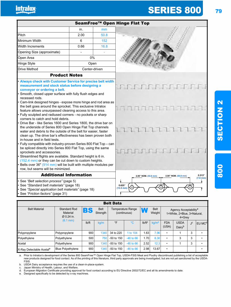
SERIES 800 79
SE
CT
ION
280
0
SeamFree™ Open Hinge Flat Topin. mm
Pitch 2.00 50.8
Minimum Width 6 152
Width Increments 0.66 16.8
Opening Size (approximate) - -
Open Area 0%
Hinge Style Open
Drive Method Center-driven
Product Notes• Always check with Customer Service for precise belt width
measurement and stock status before designing a conveyor or ordering a belt.
• Smooth, closed upper surface with fully flush edges and recessed rods.
• Cam-link designed hinges - expose more hinge and rod area as the belt goes around the sprocket. This exclusive Intralox feature allows unsurpassed cleaning access to this area.
• Fully sculpted and radiused corners - no pockets or sharp corners to catch and hold debris.
• Drive Bar - like Series 1600 and Series 1800, the drive bar on the underside of Series 800 Open Hinge Flat Top channels water and debris to the outside of the belt for easier, faster clean up. The drive bar’s effectiveness has been proven both in-house and in field tests.
• Fully compatible with industry-proven Series 800 Flat Top – can be spliced directly into Series 800 Flat Top, using the same sprockets and accessories.
• Streamlined flights are available. Standard height is 6 in. (152.4 mm) or they can be cut down to custom heights.
• Belts over 36" (914 mm) will be built with multiple modules per row, but seams will be minimized.
Additional Information• See “Belt selection process” (page 5)• See “Standard belt materials” (page 18)• See “Special application belt materials” (page 18)• See “Friction factors” (page 31)
Belt DataBelt Material Standard Rod
MaterialØ 0.24 in. (6.1 mm)
BS Belt Strength
Temperature Range (continuous) W Belt
WeightAgency Acceptabilitya
1=White, 2=Blue, 3=Natural, 4=Grey
lb/ft kg/m °F °C lb/ft² kg/m² FDA (USA)
USDADairyb
Jc EU MCd
Polypropylene Polypropylene 900 1340 34 to 220 1 to 104 1.63 7.96 • 1 3 •
Polyethylene Polyethylene 500 750 -50 to 150 -46 to 66 1.70 8.30 • 3 3 •
Acetal Polyethylene 900 1340 -50 to 150 -46 to 66 2.52 12.3 • 1 3 •
X-Ray Detectable Acetale Blue Polyethylene 900 1340 -50 to 150 -46 to 66 2.98 13.67 • •
a. Prior to Intralox’s development of the Series 800 SeamFree™ Open Hinge Flat Top, USDA-FSIS Meat and Poultry discontinued publishing a list of acceptablenew products designed for food contact. As of the printing of this literature, third party approvals are being investigated, but are not yet sanctioned by the USDA-FSIS.
b. USDA Dairy acceptance requires the use of a clean-in-place-system.c. Japan Ministry of Health, Labour, and Welfare.d. European Migration Certificate providing approval for food contact according to EU Directive 2002/72/EC and all its amendments to date.e. Designed specifically to be detected by x-ray machines.
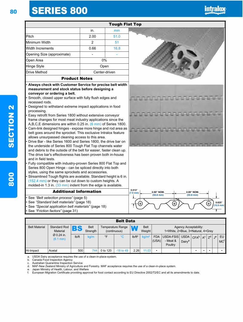
80 SERIES 800S
EC
TIO
N 2
800
Tough Flat Topin. mm
Pitch 2.00 51.0
Minimum Width 2 51
Width Increments 0.66 16.8
Opening Size (approximate) - -
Open Area 0%
Hinge Style Open
Drive Method Center-driven
Product Notes• Always check with Customer Service for precise belt width
measurement and stock status before designing a conveyor or ordering a belt.
• Smooth, closed upper surface with fully flush edges and recessed rods.
• Designed to withstand extreme impact applications in food processing.
• Easy retrofit from Series 1800 without extensive conveyor frame changes for most meat industry applications since the A,B,C,E dimensions are within 0.25 in. (6 mm) of Series 1800.
• Cam-link designed hinges - expose more hinge and rod area as belt goes around the sprocket. This exclusive Intralox feature allows unsurpassed cleaning access to this area.
• Drive Bar - like Series 1600 and Series 1800, the drive bar on the underside of Series 800 Tough Flat Top channels water and debris to the outside of the belt for easier, faster clean up. The drive bar's effectiveness has been proven both in-house and in field tests.
• Fully compatible with industry-proven Series 800 Flat Top and Series 800 Open Hinge - can be spliced directly into both styles, using the same sprockets and accessories.
• Streamlined Tough flights are available. Standard height is 6 in. (152.4 mm) or they can be cut down to custom heights. A molded-in 1.3 in. (33 mm) indent from the edge is available.
Additional Information• See “Belt selection process” (page 5)• See “Standard belt materials” (page 18)• See “Special application belt materials” (page 18)• See “Friction factors” (page 31)
2.00" NOM.(50.8 mm)
2.00" NOM.(50.8 mm)
Belt DataBelt Material Standard Rod
MaterialØ 0.24 in. (6.1 mm)
BS Belt Strength
Temperature Range (continuous) W Belt
WeightAgency Acceptability:
1=White, 2=Blue, 3=Natural, 4=Grey
lb/ft kg/m °F °C lb/ft² kg/m² FDA (USA)
USDA-FSIS - Meat & Poultry
USDADairya
CFAb Ac Zd Je EUMCf
Hi-Impact Acetal 500 744 0 to 120 -18 to 49 2.26 11.03 • • • • •
a. USDA Dairy acceptance requires the use of a clean-in-place-system.b. Canada Food Inspection Agencyc. Australian Quarantine Inspection Serviced. MAF-New Zealand Ministry of Agriculture and Forestry. MAF acceptance requires the use of a clean-in-place system.e. Japan Ministry of Health, Labour, and Welfaref. European Migration Certificate providing approval for food contact according to EU Directive 2002/72/EC and all its amendments to date.
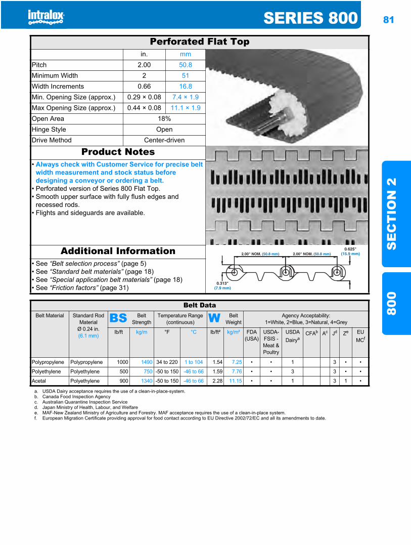
SERIES 800 81
SE
CT
ION
280
0
Perforated Flat Topin. mm
Pitch 2.00 50.8Minimum Width 2 51Width Increments 0.66 16.8Min. Opening Size (approx.) 0.29 × 0.08 7.4 × 1.9Max Opening Size (approx.) 0.44 × 0.08 11.1 × 1.9Open Area 18%Hinge Style OpenDrive Method Center-driven
Product Notes• Always check with Customer Service for precise belt
width measurement and stock status before designing a conveyor or ordering a belt.
• Perforated version of Series 800 Flat Top.• Smooth upper surface with fully flush edges and
recessed rods.• Flights and sideguards are available.
Additional Information• See “Belt selection process” (page 5)• See “Standard belt materials” (page 18)• See “Special application belt materials” (page 18)• See “Friction factors” (page 31)
Belt DataBelt Material Standard Rod
MaterialØ 0.24 in. (6.1 mm)
BS Belt Strength
Temperature Range (continuous) W Belt
WeightAgency Acceptability:
1=White, 2=Blue, 3=Natural, 4=Grey
lb/ft kg/m °F °C lb/ft² kg/m² FDA(USA)
USDA-FSIS - Meat & Poultry
USDADairya
CFAb Ac Jd Ze EU MCf
Polypropylene Polypropylene 1000 1490 34 to 220 1 to 104 1.54 7.25 • • 1 3 • •
Polyethylene Polyethylene 500 750 -50 to 150 -46 to 66 1.59 7.76 • • 3 3 • •
Acetal Polyethylene 900 1340 -50 to 150 -46 to 66 2.28 11.15 • • 1 3 1 •
a. USDA Dairy acceptance requires the use of a clean-in-place-system.b. Canada Food Inspection Agencyc. Australian Quarantine Inspection Serviced. Japan Ministry of Health, Labour, and Welfaree. MAF-New Zealand Ministry of Agriculture and Forestry. MAF acceptance requires the use of a clean-in-place system.f. European Migration Certificate providing approval for food contact according to EU Directive 2002/72/EC and all its amendments to date.
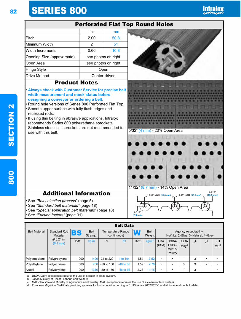
82 SERIES 800S
EC
TIO
N 2
800
Perforated Flat Top Round Holesin. mm
Pitch 2.00 50.8Minimum Width 2 51Width Increments 0.66 16.8Opening Size (approximate) see photos on rightOpen Area see photos on rightHinge Style OpenDrive Method Center-driven
Product Notes
5/32” (4 mm) - 20% Open Area
11/32” (8.7 mm) - 14% Open Area
• Always check with Customer Service for precise belt width measurement and stock status before designing a conveyor or ordering a belt.
• Round hole versions of Series 800 Perforated Flat Top.• Smooth upper surface with fully flush edges and
recessed rods.• If using this belting in abrasive applications, Intralox
recommends Series 800 polyurethane sprockets. Stainless steel split sprockets are not recommended for use with this belt.
Additional Information• See “Belt selection process” (page 5)• See “Standard belt materials” (page 18)• See “Special application belt materials” (page 18)• See “Friction factors” (page 31)
Belt DataBelt Material Standard Rod
MaterialØ 0.24 in. (6.1 mm)
BS Belt Strength
Temperature Range (continuous) W Belt
WeightAgency Acceptability:
1=White, 2=Blue, 3=Natural, 4=Grey
lb/ft kg/m °F °C lb/ft² kg/m² FDA(USA)
USDA-FSIS - Meat & Poultry
USDADairya
Jb Zc EU MCd
Polypropylene Polypropylene 1000 1490 34 to 220 1 to 104 1.54 7.52 • • 1 3 • •
Polyethylene Polyethylene 500 750 -50 to 150 -46 to 66 1.59 7.76 • • 3 3 • •
Acetal Polyethylene 900 1340 -50 to 150 -46 to 66 2.28 11.15 • • 1 3 •
a. USDA Dairy acceptance requires the use of a clean-in-place-system.b. Japan Ministry of Health, Labour, and Welfarec. MAF-New Zealand Ministry of Agriculture and Forestry. MAF acceptance requires the use of a clean-in-place system.d. European Migration Certificate providing approval for food contact according to EU Directive 2002/72/EC and all its amendments to date.
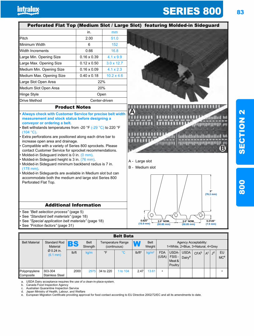
SERIES 800 83
SE
CT
ION
280
0
Perforated Flat Top (Medium Slot / Large Slot) featuring Molded-in Sideguardin. mm
Pitch 2.00 51.0
Minimum Width 6 152
Width Increments 0.66 16.8
Large Min. Opening Size 0.16 x 0.39 4.1 x 9.9
Large Max. Opening Size 0.12 x 0.50 3.0 x 12.7
Medium Min. Opening Size 0.16 x 0.09 4.1 x 2.3
Medium Max. Opening Size 0.40 x 0.18 10.2 x 4.6
Large Slot Open Area 22%
Medium Slot Open Area 20%
Hinge Style Open
Drive Method Center-driven
Product Notes• Always check with Customer Service for precise belt width
measurement and stock status before designing a conveyor or ordering a belt.
• Belt withstands temperatures from -20 °F (-29 °C) to 220 °F (104 °C).
• Extra perforations are positioned along each drive bar to increase open area and drainage.
• Compatible with a variety of Series 800 sprockets. Please contact Customer Service for sprocket recommendations.
• Molded-in Sideguard indent is 0 in. (0 mm).• Molded-in Sideguard height is 3 in. (76 mm).• Molded-in Sideguard minimum backbend radius is 7 in.
(178 mm).• Molded-in Sideguards are available in Medium slot but can
accommodate both the medium and large slot Series 800 Perforated Flat Top.
A - Large slot
B - Medium slot
Additional Information• See “Belt selection process” (page 5)• See “Standard belt materials” (page 18)• See “Special application belt materials” (page 18)• See “Friction factors” (page 31)
A
B
3"(76.2 mm)
2.0" NOM.(50.85 mm)
0.625"(15.9 mm)
2.0" NOM.(50.85 mm)
0.3125"(7.9 mm)
Belt DataBelt Material Standard Rod
MaterialØ 0.24 in. (6.1 mm)
BS Belt Strength
Temperature Range (continuous) W Belt
WeightAgency Acceptability:
1=White, 2=Blue, 3=Natural, 4=Grey
lb/ft kg/m °F °C lb/ft² kg/m² FDA(USA)
USDA-FSIS - Meat & Poultry
USDADairya
CFAb Ac Jd EU MCe
Polypropylene Composite
303-304 Stainless Steel
2000 2975 34 to 220 1 to 104 2.47 13.61 • •
a. USDA Dairy acceptance requires the use of a clean-in-place-system.b. Canada Food Inspection Agencyc. Australian Quarantine Inspection Serviced. Japan Ministry of Health, Labour, and Welfaree. European Migration Certificate providing approval for food contact according to EU Directive 2002/72/EC and all its amendments to date.
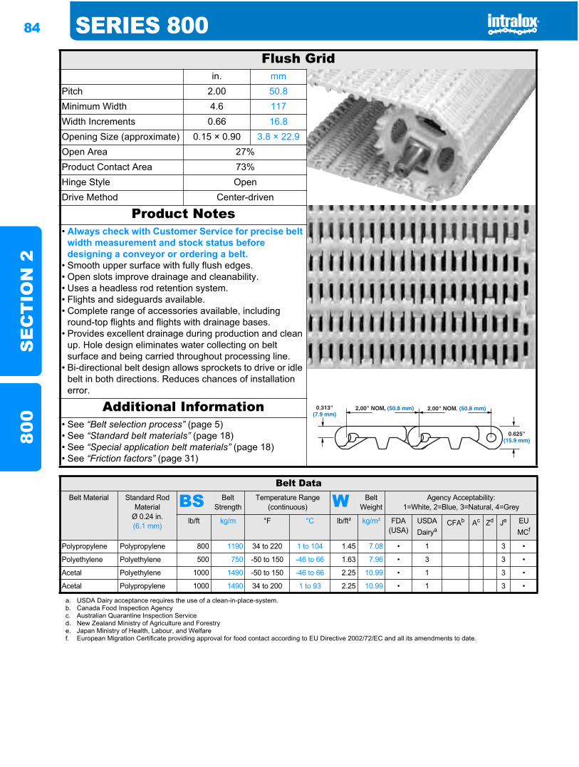
84 SERIES 800S
EC
TIO
N 2
800
Flush Gridin. mm
Pitch 2.00 50.8Minimum Width 4.6 117Width Increments 0.66 16.8Opening Size (approximate) 0.15 × 0.90 3.8 × 22.9Open Area 27%Product Contact Area 73%Hinge Style OpenDrive Method Center-driven
Product Notes• Always check with Customer Service for precise belt
width measurement and stock status before designing a conveyor or ordering a belt.
• Smooth upper surface with fully flush edges.• Open slots improve drainage and cleanability.• Uses a headless rod retention system.• Flights and sideguards available.• Complete range of accessories available, including
round-top flights and flights with drainage bases.• Provides excellent drainage during production and clean
up. Hole design eliminates water collecting on belt surface and being carried throughout processing line.
• Bi-directional belt design allows sprockets to drive or idle belt in both directions. Reduces chances of installation error.
Additional Information• See “Belt selection process” (page 5)• See “Standard belt materials” (page 18)• See “Special application belt materials” (page 18)• See “Friction factors” (page 31)
Belt DataBelt Material Standard Rod
MaterialØ 0.24 in. (6.1 mm)
BS Belt Strength
Temperature Range (continuous) W Belt
WeightAgency Acceptability:
1=White, 2=Blue, 3=Natural, 4=Grey
lb/ft kg/m °F °C lb/ft² kg/m² FDA (USA)
USDADairya
CFAb Ac Zd Je EUMCf
Polypropylene Polypropylene 800 1190 34 to 220 1 to 104 1.45 7.08 • 1 3 •
Polyethylene Polyethylene 500 750 -50 to 150 -46 to 66 1.63 7.96 • 3 3 •
Acetal Polyethylene 1000 1490 -50 to 150 -46 to 66 2.25 10.99 • 1 3 •
Acetal Polypropylene 1000 1490 34 to 200 1 to 93 2.25 10.99 • 1 3 •
a. USDA Dairy acceptance requires the use of a clean-in-place-system.b. Canada Food Inspection Agencyc. Australian Quarantine Inspection Serviced. New Zealand Ministry of Agriculture and Forestrye. Japan Ministry of Health, Labour, and Welfaref. European Migration Certificate providing approval for food contact according to EU Directive 2002/72/EC and all its amendments to date.
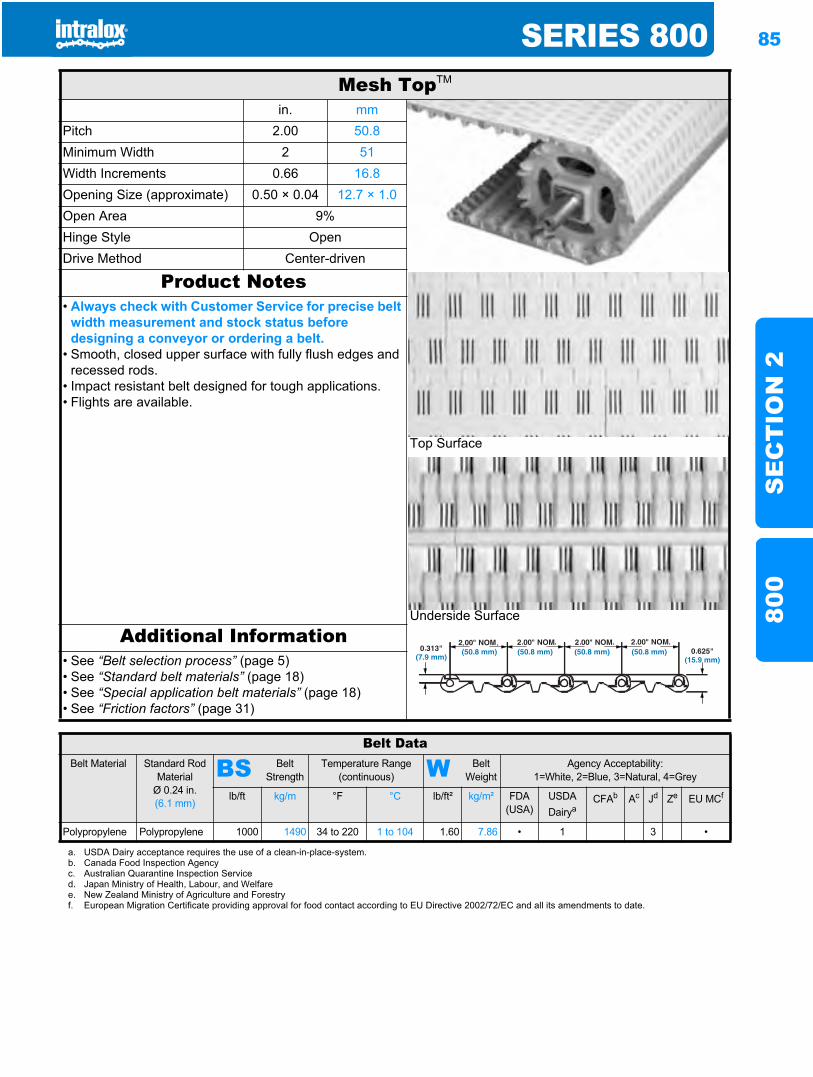
SERIES 800 85
SE
CT
ION
280
0
Mesh TopTM
in. mmPitch 2.00 50.8Minimum Width 2 51Width Increments 0.66 16.8Opening Size (approximate) 0.50 × 0.04 12.7 × 1.0Open Area 9%Hinge Style OpenDrive Method Center-driven
Product Notes
Top Surface
Underside Surface
• Always check with Customer Service for precise belt width measurement and stock status before designing a conveyor or ordering a belt.
• Smooth, closed upper surface with fully flush edges and recessed rods.
• Impact resistant belt designed for tough applications.• Flights are available.
Additional Information• See “Belt selection process” (page 5)• See “Standard belt materials” (page 18)• See “Special application belt materials” (page 18)• See “Friction factors” (page 31)
Belt DataBelt Material Standard Rod
MaterialØ 0.24 in. (6.1 mm)
BS Belt Strength
Temperature Range (continuous) W Belt
WeightAgency Acceptability:
1=White, 2=Blue, 3=Natural, 4=Grey
lb/ft kg/m °F °C lb/ft² kg/m² FDA(USA)
USDADairya
CFAb Ac Jd Ze EU MCf
Polypropylene Polypropylene 1000 1490 34 to 220 1 to 104 1.60 7.86 • 1 3 •
a. USDA Dairy acceptance requires the use of a clean-in-place-system.b. Canada Food Inspection Agencyc. Australian Quarantine Inspection Serviced. Japan Ministry of Health, Labour, and Welfaree. New Zealand Ministry of Agriculture and Forestryf. European Migration Certificate providing approval for food contact according to EU Directive 2002/72/EC and all its amendments to date.
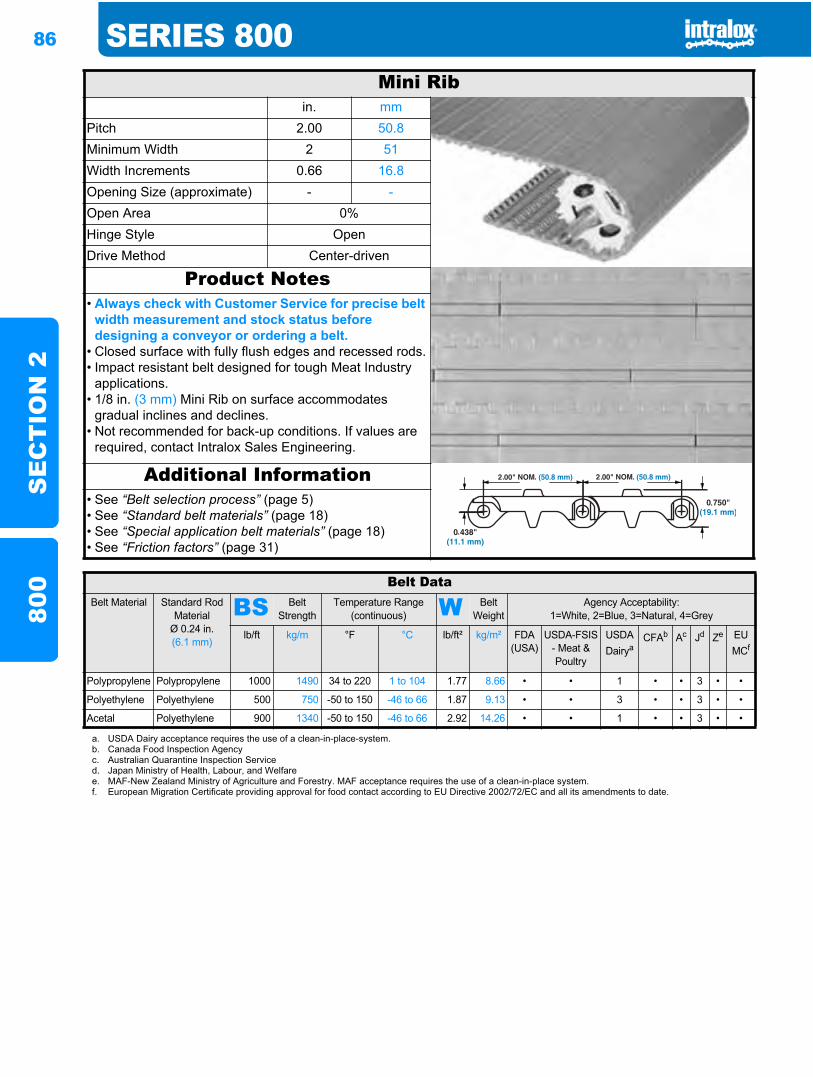
86 SERIES 800S
EC
TIO
N 2
800
Mini Ribin. mm
Pitch 2.00 50.8Minimum Width 2 51Width Increments 0.66 16.8Opening Size (approximate) - -Open Area 0%Hinge Style OpenDrive Method Center-driven
Product Notes• Always check with Customer Service for precise belt
width measurement and stock status before designing a conveyor or ordering a belt.
• Closed surface with fully flush edges and recessed rods.• Impact resistant belt designed for tough Meat Industry
applications.• 1/8 in. (3 mm) Mini Rib on surface accommodates
gradual inclines and declines.• Not recommended for back-up conditions. If values are
required, contact Intralox Sales Engineering.
Additional Information• See “Belt selection process” (page 5)• See “Standard belt materials” (page 18)• See “Special application belt materials” (page 18)• See “Friction factors” (page 31)
Belt DataBelt Material Standard Rod
MaterialØ 0.24 in. (6.1 mm)
BS Belt Strength
Temperature Range (continuous) W Belt
WeightAgency Acceptability:
1=White, 2=Blue, 3=Natural, 4=Grey
lb/ft kg/m °F °C lb/ft² kg/m² FDA(USA)
USDA-FSIS - Meat & Poultry
USDADairya
CFAb Ac Jd Ze EU MCf
Polypropylene Polypropylene 1000 1490 34 to 220 1 to 104 1.77 8.66 • • 1 • • 3 • •
Polyethylene Polyethylene 500 750 -50 to 150 -46 to 66 1.87 9.13 • • 3 • • 3 • •
Acetal Polyethylene 900 1340 -50 to 150 -46 to 66 2.92 14.26 • • 1 • • 3 • •
a. USDA Dairy acceptance requires the use of a clean-in-place-system.b. Canada Food Inspection Agencyc. Australian Quarantine Inspection Serviced. Japan Ministry of Health, Labour, and Welfaree. MAF-New Zealand Ministry of Agriculture and Forestry. MAF acceptance requires the use of a clean-in-place system.f. European Migration Certificate providing approval for food contact according to EU Directive 2002/72/EC and all its amendments to date.
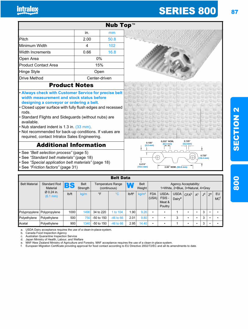
SERIES 800 87
SE
CT
ION
280
0
Nub Top™
in. mmPitch 2.00 50.8Minimum Width 4 102Width Increments 0.66 16.8Open Area 0%Product Contact Area 15%Hinge Style OpenDrive Method Center-driven
Product Notes• Always check with Customer Service for precise belt
width measurement and stock status before designing a conveyor or ordering a belt.
• Closed upper surface with fully flush edges and recessed rods.
• Standard Flights and Sideguards (without nubs) are available.
• Nub standard indent is 1.3 in. (33 mm).• Not recommended for back-up conditions. If values are
required, contact Intralox Sales Engineering.
Additional Information• See “Belt selection process” (page 5)• See “Standard belt materials” (page 18)• See “Special application belt materials” (page 18)• See “Friction factors” (page 31)
Belt DataBelt Material Standard Rod
MaterialØ 0.24 in. (6.1 mm)
BS Belt Strength
Temperature Range (continuous) W Belt
WeightAgency Acceptability:
1=White, 2=Blue, 3=Natural, 4=Grey
lb/ft kg/m °F °C lb/ft² kg/m² FDA(USA)
USDA-FSIS - Meat & Poultry
USDADairya
CFAb Ac Jd Ze EU MCf
Polypropylene Polypropylene 1000 1490 34 to 220 1 to 104 1.90 9.26 • • 1 • • 3 • •
Polyethylene Polyethylene 500 750 -50 to 150 -46 to 66 2.01 9.80 • • 3 • • 3 • •
Acetal Polyethylene 900 1340 -50 to 150 -46 to 66 2.95 14.40 • • 1 • • 3 • •
a. USDA Dairy acceptance requires the use of a clean-in-place-system.b. Canada Food Inspection Agencyc. Australian Quarantine Inspection Serviced. Japan Ministry of Health, Labour, and Welfaree. MAF-New Zealand Ministry of Agriculture and Forestry. MAF acceptance requires the use of a clean-in-place-system.f. European Migration Certificate providing approval for food contact according to EU Directive 2002/72/EC and all its amendments to date.
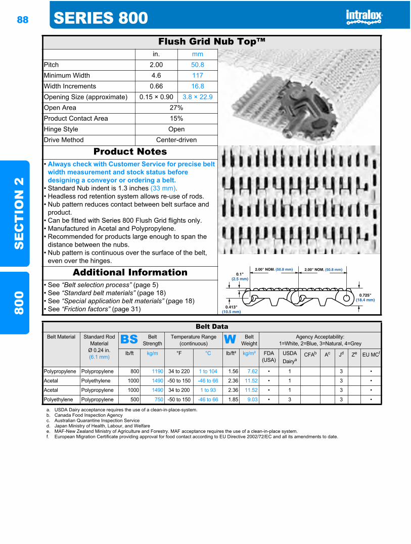
88 SERIES 800S
EC
TIO
N 2
800
Flush Grid Nub Top™in. mm
Pitch 2.00 50.8Minimum Width 4.6 117Width Increments 0.66 16.8Opening Size (approximate) 0.15 × 0.90 3.8 × 22.9Open Area 27%Product Contact Area 15%Hinge Style OpenDrive Method Center-driven
Product Notes• Always check with Customer Service for precise belt
width measurement and stock status before designing a conveyor or ordering a belt.
• Standard Nub indent is 1.3 inches (33 mm).• Headless rod retention system allows re-use of rods.• Nub pattern reduces contact between belt surface and
product.• Can be fitted with Series 800 Flush Grid flights only.• Manufactured in Acetal and Polypropylene.• Recommended for products large enough to span the
distance between the nubs.• Nub pattern is continuous over the surface of the belt,
even over the hinges.
Additional Information• See “Belt selection process” (page 5)• See “Standard belt materials” (page 18)• See “Special application belt materials” (page 18)• See “Friction factors” (page 31)
Belt DataBelt Material Standard Rod
MaterialØ 0.24 in. (6.1 mm)
BS Belt Strength
Temperature Range (continuous) W Belt
WeightAgency Acceptability:
1=White, 2=Blue, 3=Natural, 4=Grey
lb/ft kg/m °F °C lb/ft² kg/m² FDA(USA)
USDADairya
CFAb Ac Jd Ze EU MCf
Polypropylene Polypropylene 800 1190 34 to 220 1 to 104 1.56 7.62 • 1 3 •
Acetal Polyethylene 1000 1490 -50 to 150 -46 to 66 2.36 11.52 • 1 3 •
Acetal Polypropylene 1000 1490 34 to 200 1 to 93 2.36 11.52 • 1 3 •
Polyethylene Polypropylene 500 750 -50 to 150 -46 to 66 1.85 9.03 • 3 3 •
a. USDA Dairy acceptance requires the use of a clean-in-place-system.b. Canada Food Inspection Agencyc. Australian Quarantine Inspection Serviced. Japan Ministry of Health, Labour, and Welfaree. MAF-New Zealand Ministry of Agriculture and Forestry. MAF acceptance requires the use of a clean-in-place system.f. European Migration Certificate providing approval for food contact according to EU Directive 2002/72/EC and all its amendments to date.
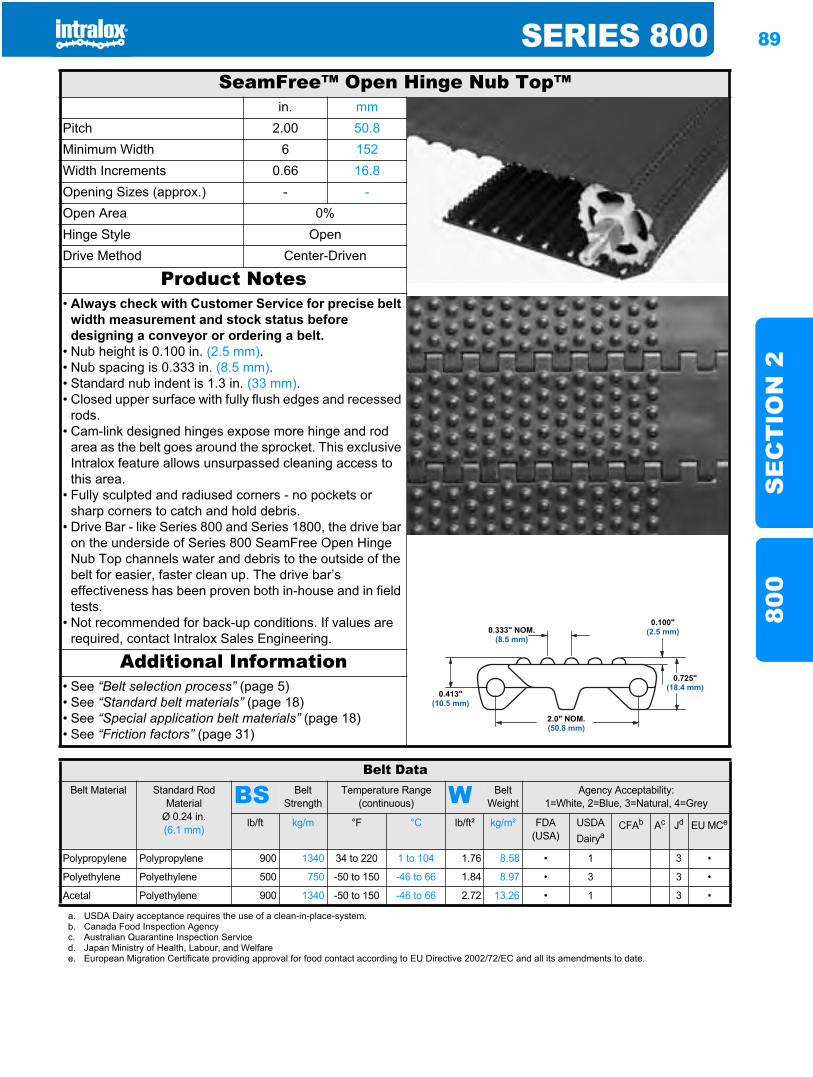
SERIES 800 89
SE
CT
ION
280
0
SeamFree™ Open Hinge Nub Top™in. mm
Pitch 2.00 50.8Minimum Width 6 152Width Increments 0.66 16.8Opening Sizes (approx.) - -Open Area 0%Hinge Style OpenDrive Method Center-Driven
Product Notes• Always check with Customer Service for precise belt
width measurement and stock status before designing a conveyor or ordering a belt.
• Nub height is 0.100 in. (2.5 mm).• Nub spacing is 0.333 in. (8.5 mm).• Standard nub indent is 1.3 in. (33 mm).• Closed upper surface with fully flush edges and recessed
rods.• Cam-link designed hinges expose more hinge and rod
area as the belt goes around the sprocket. This exclusive Intralox feature allows unsurpassed cleaning access to this area.
• Fully sculpted and radiused corners - no pockets or sharp corners to catch and hold debris.
• Drive Bar - like Series 800 and Series 1800, the drive bar on the underside of Series 800 SeamFree Open Hinge Nub Top channels water and debris to the outside of the belt for easier, faster clean up. The drive bar’s effectiveness has been proven both in-house and in field tests.
• Not recommended for back-up conditions. If values are required, contact Intralox Sales Engineering.
Additional Information• See “Belt selection process” (page 5)• See “Standard belt materials” (page 18)• See “Special application belt materials” (page 18)• See “Friction factors” (page 31)
Belt DataBelt Material Standard Rod
MaterialØ 0.24 in. (6.1 mm)
BS Belt Strength
Temperature Range (continuous) W Belt
WeightAgency Acceptability:
1=White, 2=Blue, 3=Natural, 4=Grey
lb/ft kg/m °F °C lb/ft² kg/m² FDA (USA)
USDADairya
CFAb Ac Jd EU MCe
Polypropylene Polypropylene 900 1340 34 to 220 1 to 104 1.76 8.58 • 1 3 •
Polyethylene Polyethylene 500 750 -50 to 150 -46 to 66 1.84 8.97 • 3 3 •
Acetal Polyethylene 900 1340 -50 to 150 -46 to 66 2.72 13.26 • 1 3 •
a. USDA Dairy acceptance requires the use of a clean-in-place-system.b. Canada Food Inspection Agencyc. Australian Quarantine Inspection Serviced. Japan Ministry of Health, Labour, and Welfaree. European Migration Certificate providing approval for food contact according to EU Directive 2002/72/EC and all its amendments to date.
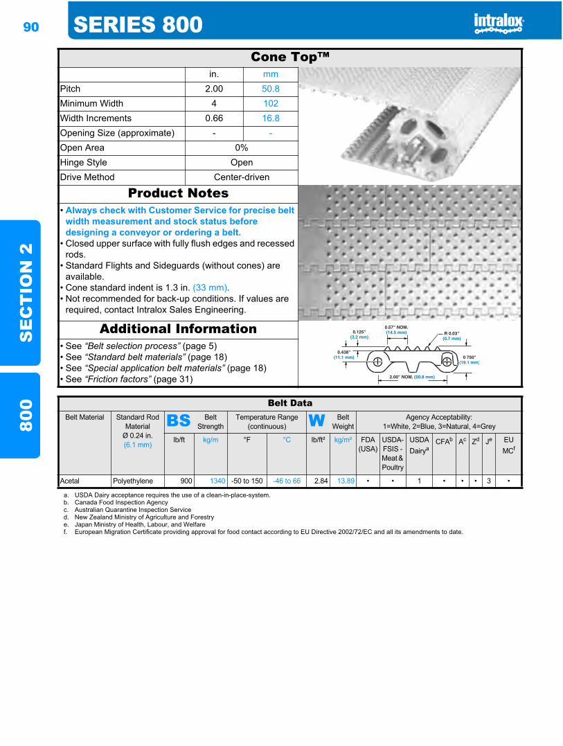
90 SERIES 800S
EC
TIO
N 2
800
Cone Top™in. mm
Pitch 2.00 50.8Minimum Width 4 102Width Increments 0.66 16.8Opening Size (approximate) - -Open Area 0%Hinge Style OpenDrive Method Center-driven
Product Notes• Always check with Customer Service for precise belt
width measurement and stock status before designing a conveyor or ordering a belt.
• Closed upper surface with fully flush edges and recessed rods.
• Standard Flights and Sideguards (without cones) are available.
• Cone standard indent is 1.3 in. (33 mm).• Not recommended for back-up conditions. If values are
required, contact Intralox Sales Engineering.
Additional Information• See “Belt selection process” (page 5)• See “Standard belt materials” (page 18)• See “Special application belt materials” (page 18)• See “Friction factors” (page 31)
Belt DataBelt Material Standard Rod
MaterialØ 0.24 in. (6.1 mm)
BS Belt Strength
Temperature Range (continuous) W Belt
WeightAgency Acceptability:
1=White, 2=Blue, 3=Natural, 4=Grey
lb/ft kg/m °F °C lb/ft² kg/m² FDA(USA)
USDA-FSIS - Meat & Poultry
USDADairya
CFAb Ac Zd Je EU MCf
Acetal Polyethylene 900 1340 -50 to 150 -46 to 66 2.84 13.89 • • 1 • • • 3 •
a. USDA Dairy acceptance requires the use of a clean-in-place-system.b. Canada Food Inspection Agencyc. Australian Quarantine Inspection Serviced. New Zealand Ministry of Agriculture and Forestrye. Japan Ministry of Health, Labour, and Welfaref. European Migration Certificate providing approval for food contact according to EU Directive 2002/72/EC and all its amendments to date.
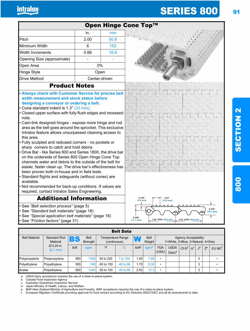
SERIES 800 91
SE
CT
ION
280
0
Open Hinge Cone Top™in. mm
Pitch 2.00 50.8Minimum Width 6 152Width Increments 0.66 16.8Opening Size (approximate) - -Open Area 0%Hinge Style OpenDrive Method Center-driven
Product Notes• Always check with Customer Service for precise belt
width measurement and stock status before designing a conveyor or ordering a belt.
• Cone standard indent is 1.3” (33 mm).• Closed upper surface with fully flush edges and recessed
rods.• Cam-link designed hinges - expose more hinge and rod
area as the belt goes around the sprocket. This exclusive Intralox feature allows unsurpassed cleaning access to this area.
• Fully sculpted and radiused corners - no pockets or sharp corners to catch and hold debris.
• Drive Bar - like Series 800 and Series 1800, the drive bar on the underside of Series 800 Open Hinge Cone Top channels water and debris to the outside of the belt for easier, faster clean up. The drive bar’s effectiveness has been proven both in-house and in field tests.
• Standard flights and sideguards (without cones) are available.
• Not recommended for back-up conditions. If values are required, contact Intralox Sales Engineering.
Additional Information• See “Belt selection process” (page 5)• See “Standard belt materials” (page 18)• See “Special application belt materials” (page 18)• See “Friction factors” (page 31)
Belt DataBelt Material Standard Rod
MaterialØ 0.24 in. (6.1 mm)
BS Belt Strength
Temperature Range (continuous) W Belt
WeightAgency Acceptability:
1=White, 2=Blue, 3=Natural, 4=Grey
lb/ft kg/m °F °C lb/ft² kg/m² FDA (USA)
USDADairya
CFAb Ac Jd Ze EU MCf
Polypropylene Polypropylene 900 1340 34 to 220 1 to 104 1.63 7.96 • 3 •
Polyethylene Polyethylene 500 740 -50 to 150 -46 to 66 1.70 8.30 • 3 •
Acetal Polyethylene 900 1340 -50 to 150 -46 to 66 2.52 12.3 • 3 •
a. USDA Dairy acceptance requires the use of a clean-in-place-system.b. Canada Food Inspection Agencyc. Australian Quarantine Inspection Serviced. Japan Ministry of Health, Labour, and Welfaree. MAF-New Zealand Ministry of Agriculture and Forestry. MAF acceptance requires the use of a clean-in-place system.f. European Migration Certificate providing approval for food contact according to EU Directive 2002/72/EC and all its amendments to date.
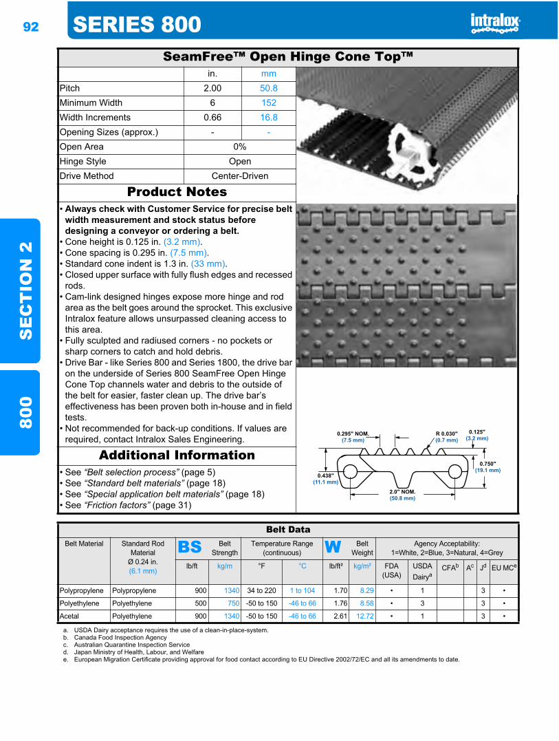
92 SERIES 800S
EC
TIO
N 2
800
SeamFree™ Open Hinge Cone Top™in. mm
Pitch 2.00 50.8Minimum Width 6 152Width Increments 0.66 16.8Opening Sizes (approx.) - -Open Area 0%Hinge Style OpenDrive Method Center-Driven
Product Notes• Always check with Customer Service for precise belt
width measurement and stock status before designing a conveyor or ordering a belt.
• Cone height is 0.125 in. (3.2 mm).• Cone spacing is 0.295 in. (7.5 mm).• Standard cone indent is 1.3 in. (33 mm).• Closed upper surface with fully flush edges and recessed
rods.• Cam-link designed hinges expose more hinge and rod
area as the belt goes around the sprocket. This exclusive Intralox feature allows unsurpassed cleaning access to this area.
• Fully sculpted and radiused corners - no pockets or sharp corners to catch and hold debris.
• Drive Bar - like Series 800 and Series 1800, the drive bar on the underside of Series 800 SeamFree Open Hinge Cone Top channels water and debris to the outside of the belt for easier, faster clean up. The drive bar’s effectiveness has been proven both in-house and in field tests.
• Not recommended for back-up conditions. If values are required, contact Intralox Sales Engineering.
Additional Information• See “Belt selection process” (page 5)• See “Standard belt materials” (page 18)• See “Special application belt materials” (page 18)• See “Friction factors” (page 31)
Belt DataBelt Material Standard Rod
MaterialØ 0.24 in. (6.1 mm)
BS Belt Strength
Temperature Range (continuous) W Belt
WeightAgency Acceptability:
1=White, 2=Blue, 3=Natural, 4=Grey
lb/ft kg/m °F °C lb/ft² kg/m² FDA (USA)
USDADairya
CFAb Ac Jd EU MCe
Polypropylene Polypropylene 900 1340 34 to 220 1 to 104 1.70 8.29 • 1 3 •
Polyethylene Polyethylene 500 750 -50 to 150 -46 to 66 1.76 8.58 • 3 3 •
Acetal Polyethylene 900 1340 -50 to 150 -46 to 66 2.61 12.72 • 1 3 •
a. USDA Dairy acceptance requires the use of a clean-in-place-system.b. Canada Food Inspection Agencyc. Australian Quarantine Inspection Serviced. Japan Ministry of Health, Labour, and Welfaree. European Migration Certificate providing approval for food contact according to EU Directive 2002/72/EC and all its amendments to date.
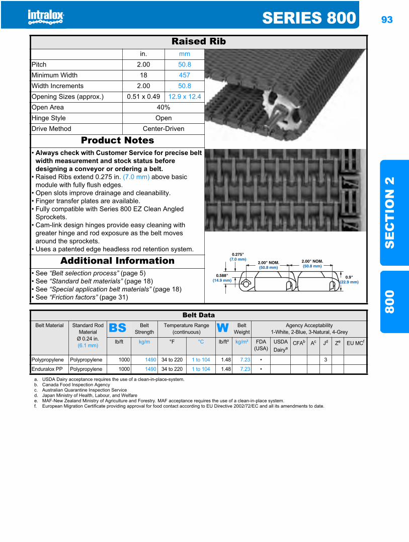
SERIES 800 93
SE
CT
ION
280
0
Raised Ribin. mm
Pitch 2.00 50.8Minimum Width 18 457Width Increments 2.00 50.8Opening Sizes (approx.) 0.51 x 0.49 12.9 x 12.4Open Area 40%Hinge Style OpenDrive Method Center-Driven
Product Notes• Always check with Customer Service for precise belt
width measurement and stock status before designing a conveyor or ordering a belt.
• Raised Ribs extend 0.275 in. (7.0 mm) above basic module with fully flush edges.
• Open slots improve drainage and cleanability.• Finger transfer plates are available.• Fully compatible with Series 800 EZ Clean Angled
Sprockets.• Cam-link design hinges provide easy cleaning with
greater hinge and rod exposure as the belt moves around the sprockets.
• Uses a patented edge headless rod retention system.
Additional Information• See “Belt selection process” (page 5)• See “Standard belt materials” (page 18)• See “Special application belt materials” (page 18)• See “Friction factors” (page 31)
Belt DataBelt Material Standard Rod
MaterialØ 0.24 in. (6.1 mm)
BS Belt Strength
Temperature Range (continuous) W Belt
WeightAgency Acceptability
1-White, 2-Blue, 3-Natural, 4-Grey
lb/ft kg/m °F °C lb/ft² kg/m² FDA (USA)
USDADairya
CFAb Ac Jd Ze EU MCf
Polypropylene Polypropylene 1000 1490 34 to 220 1 to 104 1.48 7.23 • 3
Enduralox PP Polypropylene 1000 1490 34 to 220 1 to 104 1.48 7.23 •
a. USDA Dairy acceptance requires the use of a clean-in-place-system.b. Canada Food Inspection Agencyc. Australian Quarantine Inspection Serviced. Japan Ministry of Health, Labour, and Welfaree. MAF-New Zealand Ministry of Agriculture and Forestry. MAF acceptance requires the use of a clean-in-place system.f. European Migration Certificate providing approval for food contact according to EU Directive 2002/72/EC and all its amendments to date.
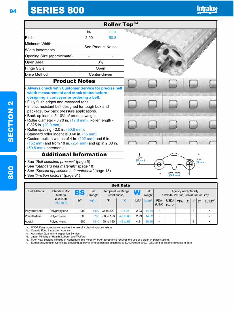
94 SERIES 800S
EC
TIO
N 2
800
Roller TopTM
in. mmPitch 2.00 50.8Minimum Width
See Product NotesWidth IncrementsOpening Size (approximate) - -Open Area 3%Hinge Style OpenDrive Method Center-driven
Product Notes• Always check with Customer Service for precise belt
width measurement and stock status before designing a conveyor or ordering a belt.
• Fully flush edges and recessed rods.• Impact resistant belt designed for tough box and
package, low back pressure applications.• Back-up load is 5-10% of product weight.• Roller diameter - 0.70 in. (17.8 mm). Roller length -
0.825 in. (20.9 mm).• Roller spacing - 2.0 in. (50.8 mm).• Standard roller indent is 0.60 in. (15 mm)• Custom-built in widths of 4 in. (102 mm) and 6 in.
(152 mm) and from 10 in. (254 mm) and up in 2.00 in. (50.8 mm) increments.
Additional Information• See “Belt selection process” (page 5)• See “Standard belt materials” (page 18)• See “Special application belt materials” (page 18)• See “Friction factors” (page 31)
Belt DataBelt Material Standard Rod
MaterialØ 0.24 in. (6.1 mm)
BS Belt Strength
Temperature Range (continuous) W Belt
WeightAgency Acceptability:
1=White, 2=Blue, 3=Natural, 4=Grey
lb/ft kg/m °F °C lb/ft² kg/m² FDA (USA)
USDADairya
CFAb Ac Jd Ze EU MCf
Polypropylene Polypropylene 1000 1490 34 to 200 1 to 93 2.93 14.34 • 3 •
Polyethylene Polyethylene 500 750 -50 to 150 -46 to 66 2.99 14.62 • 3 •
Acetal Polyethylene 900 1340 -50 to 150 -46 to 66 4.11 20.10 • 3 •
a. USDA Dairy acceptance requires the use of a clean-in-place-system.b. Canada Food Inspection Agencyc. Australian Quarantine Inspection Serviced. Japan Ministry of Health, Labour, and Welfaree. MAF-New Zealand Ministry of Agriculture and Forestry. MAF acceptance requires the use of a clean-in-place system.f. European Migration Certificate providing approval for food contact according to EU Directive 2002/72/EC and all its amendments to date.
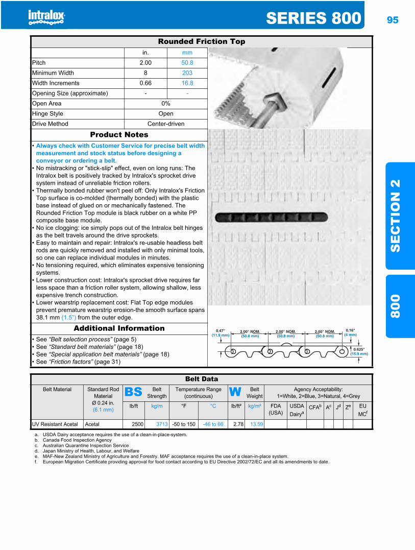
SERIES 800 95
SE
CT
ION
280
0
Rounded Friction Topin. mm
Pitch 2.00 50.8
Minimum Width 8 203
Width Increments 0.66 16.8
Opening Size (approximate) - -
Open Area 0%
Hinge Style Open
Drive Method Center-driven
Product Notes• Always check with Customer Service for precise belt width
measurement and stock status before designing a conveyor or ordering a belt.
• No mistracking or "stick-slip" effect, even on long runs: The Intralox belt is positively tracked by Intralox's sprocket drive system instead of unreliable friction rollers.
• Thermally bonded rubber won't peel off: Only Intralox's Friction Top surface is co-molded (thermally bonded) with the plastic base instead of glued on or mechanically fastened. The Rounded Friction Top module is black rubber on a white PP composite base module.
• No ice clogging: ice simply pops out of the Intralox belt hinges as the belt travels around the drive sprockets.
• Easy to maintain and repair: Intralox's re-usable headless belt rods are quickly removed and installed with only minimal tools, so one can replace individual modules in minutes.
• No tensioning required, which eliminates expensive tensioning systems.
• Lower construction cost: Intralox's sprocket drive requires far less space than a friction roller system, allowing shallow, less expensive trench construction.
• Lower wearstrip replacement cost: Flat Top edge modules prevent premature wearstrip erosion-the smooth surface spans 38.1 mm (1.5”) from the outer edge.
Additional Information• See “Belt selection process” (page 5)• See “Standard belt materials” (page 18)• See “Special application belt materials” (page 18)• See “Friction factors” (page 31)
Belt DataBelt Material Standard Rod
MaterialØ 0.24 in. (6.1 mm)
BS Belt Strength
Temperature Range (continuous) W Belt
WeightAgency Acceptability:
1=White, 2=Blue, 3=Natural, 4=Grey
lb/ft kg/m °F °C lb/ft² kg/m² FDA(USA)
USDADairya
CFAb Ac Jd Ze EU MCf
UV Resistant Acetal Acetal 2500 3713 -50 to 150 -46 to 66 2.78 13.59
a. USDA Dairy acceptance requires the use of a clean-in-place-system.b. Canada Food Inspection Agencyc. Australian Quarantine Inspection Serviced. Japan Ministry of Health, Labour, and Welfaree. MAF-New Zealand Ministry of Agriculture and Forestry. MAF acceptance requires the use of a clean-in-place system.f. European Migration Certificate providing approval for food contact according to EU Directive 2002/72/EC and all its amendments to date.

96 SERIES 800S
EC
TIO
N 2
800
Sprocket and Support Quantity ReferenceBelt Width Rangea Minimum Number of
Sprockets Per ShaftbWearstrips
in. mm Carryway Returnway
2 51 1 2 2
4 102 1 2 2
6 152 2 2 2
8 203 2 2 2
10 254 2 3 2
12 305 3 3 2
14 356 3 3 3
16 406 3 3 3
18 457 3 3 3
20 508 5 4 3
24 610 5 4 3
30 762 5 5 4
32 813 7 5 4
36 914 7 5 4
42 1067 7 6 5
48 1219 9 7 5
54 1372 9 7 6
60 1524 11 8 6
72 1829 13 9 7
84 2134 15 11 8
96 2438 17 12 9
120 3048 21 15 11
144 3658 25 17 13
For Other Widths, Use Odd Number of Sprocketsc at Maximum 6 in. (152 mm) CL Spacing
Maximum 9 in. (229 mm) CL Spacing Maximum 12 in. (305 mm) CL Spacing
a. If your belt width exceeds a number listed in the table, please refer to the sprocket and support material minimums for the next larger width range listed. Beltsare available in 0.66 in. (16.8 mm) increments beginning with minimum width of 2 in. (51 mm). If the actual width is critical, consult Customer Service.
b. These are the minimum number of sprockets. Additional sprockets may be required for heavily loaded applications.Polyurethane sprockets require a maximum4 in. (102 mm) centerline spacing.
c. The center sprocket should be locked down. With only two sprockets, fix the sprocket on the drive journal side only. See Retainer Rings/Center Sprocket Offsetchart on page 304 for lock down location.
S Strength Factor
SPEED/LENGTH RATIO (V/L)
V = ft/min (m/min) Divide belt speed “V” by the shaft CL distance “L”. Strength Factor is found at intersection of speed/length ratio and appropriate sprocket line. See page 36 for more information.T = number of teeth
L = ft (m)
Sprocket Spacing as a Function of Belt Strength Utilized
SPRO
CKET
SPA
CING
, in.
SPROCKET SPACING
, mm
PERCENT OF ALLOWABLE BELT STRENGTH UTILIZED, %
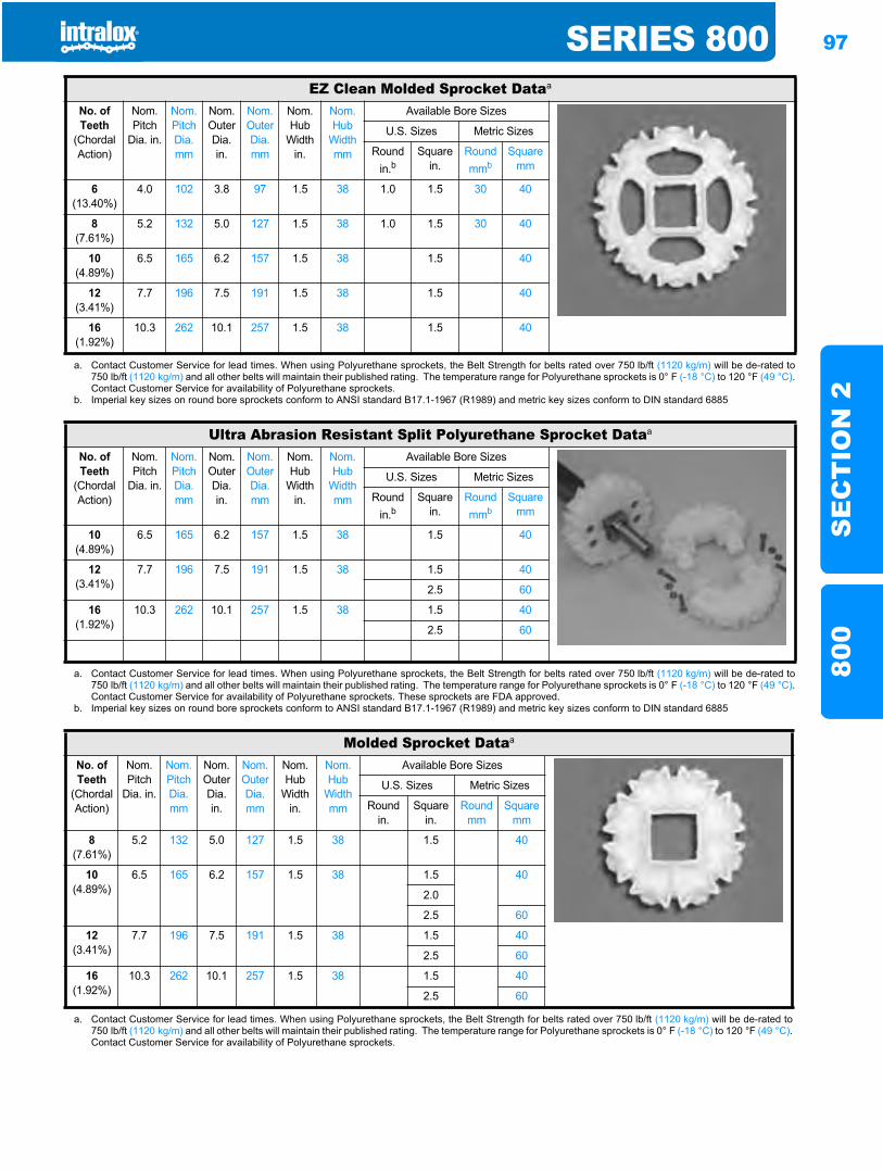
SERIES 800 97
SE
CT
ION
280
0
EZ Clean Molded Sprocket Dataa
No. of Teeth
(Chordal Action)
Nom. Pitch
Dia. in.
Nom. Pitch Dia. mm
Nom. Outer Dia.in.
Nom. Outer Dia.mm
Nom. Hub
Width in.
Nom. Hub
Width mm
Available Bore Sizes
U.S. Sizes Metric Sizes
Round in.b
Square in.
Round mmb
Square mm
6(13.40%)
4.0 102 3.8 97 1.5 38 1.0 1.5 30 40
8(7.61%)
5.2 132 5.0 127 1.5 38 1.0 1.5 30 40
10(4.89%)
6.5 165 6.2 157 1.5 38 1.5 40
12(3.41%)
7.7 196 7.5 191 1.5 38 1.5 40
16(1.92%)
10.3 262 10.1 257 1.5 38 1.5 40
a. Contact Customer Service for lead times. When using Polyurethane sprockets, the Belt Strength for belts rated over 750 lb/ft (1120 kg/m) will be de-rated to750 lb/ft (1120 kg/m) and all other belts will maintain their published rating. The temperature range for Polyurethane sprockets is 0° F (-18 °C) to 120 °F (49 °C).Contact Customer Service for availability of Polyurethane sprockets.
b. Imperial key sizes on round bore sprockets conform to ANSI standard B17.1-1967 (R1989) and metric key sizes conform to DIN standard 6885
Ultra Abrasion Resistant Split Polyurethane Sprocket Dataa
No. of Teeth
(Chordal Action)
Nom. Pitch
Dia. in.
Nom. Pitch Dia. mm
Nom. Outer Dia.in.
Nom. Outer Dia.mm
Nom. Hub
Width in.
Nom. Hub
Width mm
Available Bore Sizes
U.S. Sizes Metric Sizes
Round in.b
Square in.
Round mmb
Square mm
10(4.89%)
6.5 165 6.2 157 1.5 38 1.5 40
12(3.41%)
7.7 196 7.5 191 1.5 38 1.5 40
2.5 60
16(1.92%)
10.3 262 10.1 257 1.5 38 1.5 40
2.5 60
a. Contact Customer Service for lead times. When using Polyurethane sprockets, the Belt Strength for belts rated over 750 lb/ft (1120 kg/m) will be de-rated to750 lb/ft (1120 kg/m) and all other belts will maintain their published rating. The temperature range for Polyurethane sprockets is 0° F (-18 °C) to 120 °F (49 °C).Contact Customer Service for availability of Polyurethane sprockets. These sprockets are FDA approved.
b. Imperial key sizes on round bore sprockets conform to ANSI standard B17.1-1967 (R1989) and metric key sizes conform to DIN standard 6885
Molded Sprocket Dataa
No. of Teeth
(Chordal Action)
Nom. Pitch
Dia. in.
Nom. Pitch Dia. mm
Nom. Outer Dia.in.
Nom. Outer Dia.mm
Nom. Hub
Width in.
Nom. Hub
Width mm
Available Bore Sizes
U.S. Sizes Metric Sizes
Round in.
Square in.
Round mm
Square mm
8(7.61%)
5.2 132 5.0 127 1.5 38 1.5 40
10(4.89%)
6.5 165 6.2 157 1.5 38 1.5 40
2.0
2.5 60
12(3.41%)
7.7 196 7.5 191 1.5 38 1.5 40
2.5 60
16(1.92%)
10.3 262 10.1 257 1.5 38 1.5 40
2.5 60
a. Contact Customer Service for lead times. When using Polyurethane sprockets, the Belt Strength for belts rated over 750 lb/ft (1120 kg/m) will be de-rated to750 lb/ft (1120 kg/m) and all other belts will maintain their published rating. The temperature range for Polyurethane sprockets is 0° F (-18 °C) to 120 °F (49 °C).Contact Customer Service for availability of Polyurethane sprockets.
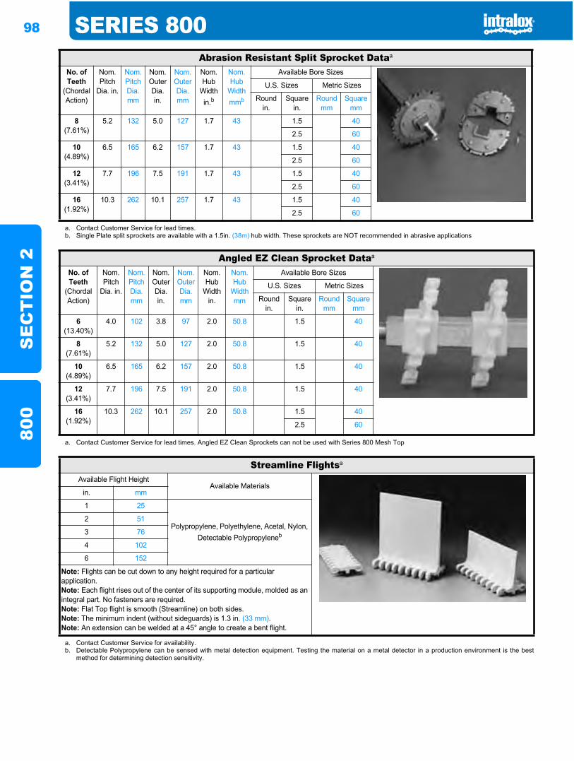
98 SERIES 800S
EC
TIO
N 2
800
Abrasion Resistant Split Sprocket Dataa
No. of Teeth
(Chordal Action)
Nom. Pitch
Dia. in.
Nom. Pitch Dia. mm
Nom. Outer Dia.in.
Nom. Outer Dia.mm
Nom. Hub
Width in.b
Nom. Hub
Width mmb
Available Bore Sizes
U.S. Sizes Metric Sizes
Round in.
Square in.
Round mm
Square mm
8(7.61%)
5.2 132 5.0 127 1.7 43 1.5 40
2.5 60
10(4.89%)
6.5 165 6.2 157 1.7 43 1.5 40
2.5 60
12(3.41%)
7.7 196 7.5 191 1.7 43 1.5 40
2.5 60
16(1.92%)
10.3 262 10.1 257 1.7 43 1.5 40
2.5 60
a. Contact Customer Service for lead times.b. Single Plate split sprockets are available with a 1.5in. (38m) hub width. These sprockets are NOT recommended in abrasive applications
Angled EZ Clean Sprocket Dataa
No. of Teeth
(Chordal Action)
Nom. Pitch
Dia. in.
Nom. Pitch Dia. mm
Nom. Outer Dia.in.
Nom. Outer Dia.mm
Nom. Hub
Width in.
Nom. Hub
Width mm
Available Bore Sizes
U.S. Sizes Metric Sizes
Round in.
Square in.
Round mm
Square mm
6(13.40%)
4.0 102 3.8 97 2.0 50.8 1.5 40
8(7.61%)
5.2 132 5.0 127 2.0 50.8 1.5 40
10(4.89%)
6.5 165 6.2 157 2.0 50.8 1.5 40
12(3.41%)
7.7 196 7.5 191 2.0 50.8 1.5 40
16(1.92%)
10.3 262 10.1 257 2.0 50.8 1.5 40
2.5 60
a. Contact Customer Service for lead times. Angled EZ Clean Sprockets can not be used with Series 800 Mesh Top
Streamline Flightsa
Available Flight HeightAvailable Materials
in. mm
1 25
Polypropylene, Polyethylene, Acetal, Nylon, Detectable Polypropyleneb
2 51
3 76
4 102
6 152
Note: Flights can be cut down to any height required for a particular application.Note: Each flight rises out of the center of its supporting module, molded as an integral part. No fasteners are required.Note: Flat Top flight is smooth (Streamline) on both sides.Note: The minimum indent (without sideguards) is 1.3 in. (33 mm).Note: An extension can be welded at a 45° angle to create a bent flight.
a. Contact Customer Service for availability.b. Detectable Polypropylene can be sensed with metal detection equipment. Testing the material on a metal detector in a production environment is the best
method for determining detection sensitivity.
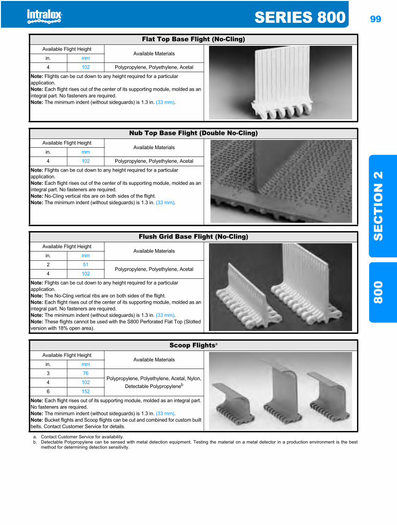
SERIES 800 99
SE
CT
ION
280
0
Flat Top Base Flight (No-Cling)Available Flight Height
Available Materialsin. mm
4 102 Polypropylene, Polyethylene, Acetal
Note: Flights can be cut down to any height required for a particular application.Note: Each flight rises out of the center of its supporting module, molded as an integral part. No fasteners are required.Note: The minimum indent (without sideguards) is 1.3 in. (33 mm).
Nub Top Base Flight (Double No-Cling)Available Flight Height
Available Materialsin. mm
4 102 Polypropylene, Polyethylene, Acetal
Note: Flights can be cut down to any height required for a particular application.Note: Each flight rises out of the center of its supporting module, molded as an integral part. No fasteners are required.Note: No-Cling vertical ribs are on both sides of the flight.Note: The minimum indent (without sideguards) is 1.3 in. (33 mm).
Flush Grid Base Flight (No-Cling)Available Flight Height
Available Materialsin. mm
2 51Polypropylene, Polyethylene, Acetal
4 102
Note: Flights can be cut down to any height required for a particular application.Note: The No-Cling vertical ribs are on both sides of the flight.Note: Each flight rises out of the center of its supporting module, molded as an integral part. No fasteners are required.Note: The minimum indent (without sideguards) is 1.3 in. (33 mm).Note: These flights cannot be used with the S800 Perforated Flat Top (Slotted version with 18% open area).
Scoop Flightsa
Available Flight HeightAvailable Materials
in. mm
3 76Polypropylene, Polyethylene, Acetal, Nylon,
Detectable Polypropyleneb4 102
6 152
Note: Each flight rises out of its supporting module, molded as an integral part. No fasteners are required.Note: The minimum indent (without sideguards) is 1.3 in. (33 mm).Note: Bucket flights and Scoop flights can be cut and combined for custom built belts. Contact Customer Service for details.
a. Contact Customer Service for availability.b. Detectable Polypropylene can be sensed with metal detection equipment. Testing the material on a metal detector in a production environment is the best
method for determining detection sensitivity.
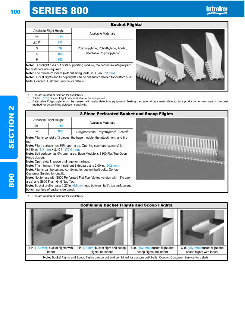
100 SERIES 800S
EC
TIO
N 2
800
Bucket Flightsa
Available Flight HeightAvailable Materials
in. mm
2.25b 57b
Polypropylene, Polyethylene, Acetal, Detectable Polypropylenec
3 76
4 102
6 152
Note: Each flight rises out of its supporting module, molded as an integral part. No fasteners are required.Note: The minimum indent (without sideguards) is 1.3 in. (33 mm).Note: Bucket flights and Scoop flights can be cut and combined for custom built belts. Contact Customer Service for details.
a. Contact Customer Service for availability.b. 2.25in. (57m) Bucket Flight only available in Polypropylene.c. Detectable Polypropylene can be sensed with metal detection equipment. Testing the material on a metal detector in a production environment is the best
method for determining detection sensitivity.
3-Piece Perforated Bucket and Scoop FlightsAvailable Flight Height
Available Materialsin. mm
4 102 Polypropylene, Polyethylenea, Acetala
Note: Flights consist of 3 pieces: the base module, the attachment, and the rod.Note: Flight surface has 30% open area. Opening size (approximate) is 0.130 in. (3.3 mm) × 2.40 in. (70.0 mm).Note: Belt surface has 0% open area. Base Module is S800 Flat Top Open Hinge design.Note: Open slots improve drainage for inclines.Note: The minimum indent (without Sideguards) is 2.00 in. (50.8 mm).Note: Flights can be cut and combined for custom built belts. Contact Customer Service for details.Note: Not for use with S800 Perforated Flat Top (slotted version with 18% open area) and S800 Flush Grid Nub Top. Note: Bucket profile has a 0.27 in. (6.9 mm) gap between belt's top surface and bottom surface of bucket side panel.
a. Contact Customer Service for availability.
Combining Bucket Flights and Scoop Flights
6 in. (152 mm) bucket flights with indent
3 in. (76 mm) bucket flight and scoop flights, no indent
4 in. (102 mm) bucket flight and scoop flights, no indent
6 in. (152 mm) bucket flight and scoop flights with indent
Note: Bucket flights and Scoop flights can be cut and combined for custom built belts. Contact Customer Service for details.
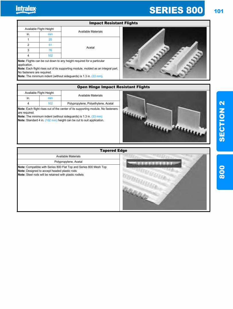
SERIES 800 101
SE
CT
ION
280
0
Impact Resistant FlightsAvailable Flight Height
Available Materialsin. mm
1 25
Acetal2 51
3 76
4 102
Note: Flights can be cut down to any height required for a particular application.Note: Each flight rises out of its supporting module, molded as an integral part. No fasteners are required.Note: The minimum indent (without sideguards) is 1.3 in. (33 mm).
Open Hinge Impact Resistant FlightsAvailable Flight Height
Available Materialsin. mm
4 102 Polypropylene, Polyethylene, Acetal
Note: Each flight rises out of the center of its supporting module. No fasteners are required.Note: The minimum indent (without sideguards) is 1.3 in. (33 mm)Note: Standard 4 in. (102 mm) height can be cut to suit application.
Tapered EdgeAvailable Materials
Polypropylene, Acetal
Note: Compatible with Series 800 Flat Top and Series 800 Mesh TopNote: Designed to accept headed plastic rodsNote: Steel rods will be retained with plastic rodlets
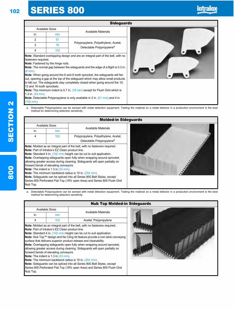
102 SERIES 800S
EC
TIO
N 2
800
SideguardsAvailable Sizes
Available Materialsin. mm
2 51Polypropylene, Polyethylene, Acetal,
Detectable Polypropylenea3 76
4 102
Note: Standard overlapping design and are an integral part of the belt, with no fasteners required.Note: Fastened by the hinge rods.Note: The normal gap between the sideguards and the edge of a flight is 0.3 in. (8 mm).Note: When going around the 6 and 8 tooth sprocket, the sideguards will fan out, opening a gap at the top of the sideguard which may allow small products to fall out. The sideguards stay completely closed when going around the 10, 12 and 16 tooth sprockets.Note: The minimum indent is 0.7 in. (18 mm) except for Flush Grid which is 1.3 in. (33 mm).Note: Detectable Polypropylene is only available in 2 in. (51 mm) and 4 in. (102 mm).
a. Detectable Polypropylene can be sensed with metal detection equipment. Testing the material on a metal detector in a production environment is the bestmethod for determining detection sensitivity.
Molded-in SideguardsAvailable Sizes
Available Materialsin. mm
4 102 Polypropylene, Polyethylene, Acetal, Detectable Polypropylenea
Note: Molded as an integral part of the belt, with no fasteners required.Note: Part of Intralox’s EZ Clean product line.Note: Standard 4 in. (102 mm) height can be cut to suit application.Note: Overlapping sideguards open fully when wrapping around sprocket, allowing greater access during cleaning. Sideguards will open partially on forward bends of elevating conveyors.Note: The indent is 1.3 in (33 mm).Note: The minimum backbend radius is 10 in. (254 mm).Note: Sideguards can be spliced into all Series 800 Belt Styles, except Series 800 Perforated Flat Top (18% open Area) and Series 800 Flush Grid Nub Top.
a. Detectable Polypropylene can be sensed with metal detection equipment. Testing the material on a metal detector in a production environment is the bestmethod for determining detection sensitivity.
Nub Top Molded-in SideguardsAvailable Sizes
Available Materialsin. mm
4 102 Acetal, Polypropylene
Note: Molded as an integral part of the belt, with no fasteners required.Note: Part of Intralox’s EZ Clean product line.Note: Standard 4 in. (102 mm) height can be cut to suit application.Note: Nub Top™ design and No Cling rib feature provide a non-stick conveying surface that delivers superior product release and cleanability.Note: Overlapping sideguards open fully when wrapping around sprocket, allowing greater access during cleaning. Sideguards will open partially on forward bends of elevating conveyors.Note: The indent is 1.3 in (33 mm).Note: The minimum backbend radius is 10 in. (254 mm).Note: Sideguards can be spliced into all Series 800 Belt Styles, except Series 800 Perforated Flat Top (18% open Area) and Series 800 Flush Grid Nub Top.
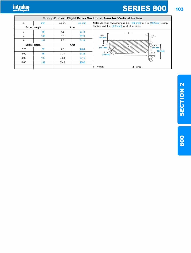
SERIES 800 103
SE
CT
ION
280
0
Scoop/Bucket Flight Cross Sectional Area for Vertical Inclinein. mm sq. in. sq. mm Note: Minimum row spacing is 6 in. (152 mm) for 6 in. (152 mm) Scoop/
Buckets and 4 in. (102 mm) for all other sizes.Scoop Height Area
3 76 4.3 2774
4 102 6.0 3871
6 152 9.5 6129
Bucket Height Area
2.25 57 2.3 1484
3.00 76 3.31 2135
4.00 102 4.68 3019
6.00 152 7.45 4806
1 - Height 2 - Area
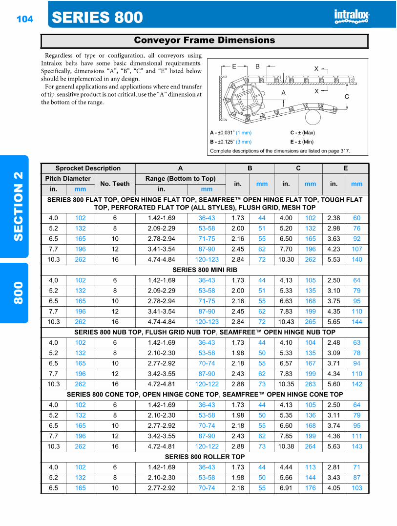
104 SERIES 800S
EC
TIO
N 2
800
Regardless of type or configuration, all conveyors usingIntralox belts have some basic dimensional requirements.Specifically, dimensions “A”, “B”, “C” and “E” listed belowshould be implemented in any design.
For general applications and applications where end transferof tip-sensitive product is not critical, use the “A” dimension atthe bottom of the range.
Conveyor Frame Dimensions
A - ±0.031” (1 mm) C - ± (Max)
B - ±0.125” (3 mm) E - ± (Min)
Complete descriptions of the dimensions are listed on page 317.
Sprocket Description A B C EPitch Diameter
No. TeethRange (Bottom to Top)
in. mm in. mm in. mmin. mm in. mm
SERIES 800 FLAT TOP, OPEN HINGE FLAT TOP, SEAMFREE™ OPEN HINGE FLAT TOP, TOUGH FLAT TOP, PERFORATED FLAT TOP (ALL STYLES), FLUSH GRID, MESH TOP
4.0 102 6 1.42-1.69 36-43 1.73 44 4.00 102 2.38 605.2 132 8 2.09-2.29 53-58 2.00 51 5.20 132 2.98 766.5 165 10 2.78-2.94 71-75 2.16 55 6.50 165 3.63 927.7 196 12 3.41-3.54 87-90 2.45 62 7.70 196 4.23 10710.3 262 16 4.74-4.84 120-123 2.84 72 10.30 262 5.53 140
SERIES 800 MINI RIB4.0 102 6 1.42-1.69 36-43 1.73 44 4.13 105 2.50 645.2 132 8 2.09-2.29 53-58 2.00 51 5.33 135 3.10 796.5 165 10 2.78-2.94 71-75 2.16 55 6.63 168 3.75 957.7 196 12 3.41-3.54 87-90 2.45 62 7.83 199 4.35 11010.3 262 16 4.74-4.84 120-123 2.84 72 10.43 265 5.65 144
SERIES 800 NUB TOP, FLUSH GRID NUB TOP, SEAMFREE™ OPEN HINGE NUB TOP4.0 102 6 1.42-1.69 36-43 1.73 44 4.10 104 2.48 635.2 132 8 2.10-2.30 53-58 1.98 50 5.33 135 3.09 786.5 165 10 2.77-2.92 70-74 2.18 55 6.57 167 3.71 947.7 196 12 3.42-3.55 87-90 2.43 62 7.83 199 4.34 11010.3 262 16 4.72-4.81 120-122 2.88 73 10.35 263 5.60 142
SERIES 800 CONE TOP, OPEN HINGE CONE TOP, SEAMFREE™ OPEN HINGE CONE TOP4.0 102 6 1.42-1.69 36-43 1.73 44 4.13 105 2.50 645.2 132 8 2.10-2.30 53-58 1.98 50 5.35 136 3.11 796.5 165 10 2.77-2.92 70-74 2.18 55 6.60 168 3.74 957.7 196 12 3.42-3.55 87-90 2.43 62 7.85 199 4.36 111
10.3 262 16 4.72-4.81 120-122 2.88 73 10.38 264 5.63 143SERIES 800 ROLLER TOP
4.0 102 6 1.42-1.69 36-43 1.73 44 4.44 113 2.81 715.2 132 8 2.10-2.30 53-58 1.98 50 5.66 144 3.43 876.5 165 10 2.77-2.92 70-74 2.18 55 6.91 176 4.05 103
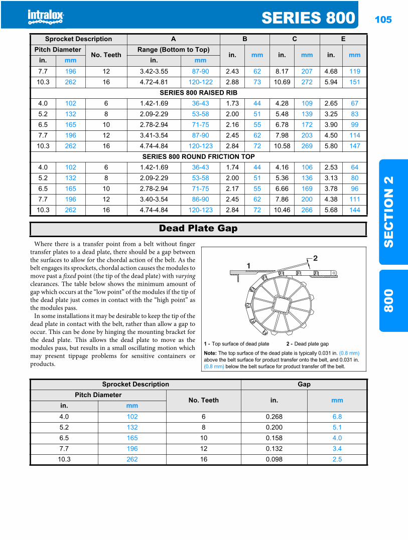
SERIES 800 105
SE
CT
ION
280
0
Where there is a transfer point from a belt without fingertransfer plates to a dead plate, there should be a gap betweenthe surfaces to allow for the chordal action of the belt. As thebelt engages its sprockets, chordal action causes the modules tomove past a fixed point (the tip of the dead plate) with varyingclearances. The table below shows the minimum amount ofgap which occurs at the “low point” of the modules if the tip ofthe dead plate just comes in contact with the “high point” asthe modules pass.
In some installations it may be desirable to keep the tip of thedead plate in contact with the belt, rather than allow a gap tooccur. This can be done by hinging the mounting bracket forthe dead plate. This allows the dead plate to move as themodules pass, but results in a small oscillating motion whichmay present tippage problems for sensitive containers orproducts.
7.7 196 12 3.42-3.55 87-90 2.43 62 8.17 207 4.68 11910.3 262 16 4.72-4.81 120-122 2.88 73 10.69 272 5.94 151
SERIES 800 RAISED RIB4.0 102 6 1.42-1.69 36-43 1.73 44 4.28 109 2.65 675.2 132 8 2.09-2.29 53-58 2.00 51 5.48 139 3.25 836.5 165 10 2.78-2.94 71-75 2.16 55 6.78 172 3.90 997.7 196 12 3.41-3.54 87-90 2.45 62 7.98 203 4.50 11410.3 262 16 4.74-4.84 120-123 2.84 72 10.58 269 5.80 147
SERIES 800 ROUND FRICTION TOP4.0 102 6 1.42-1.69 36-43 1.74 44 4.16 106 2.53 645.2 132 8 2.09-2.29 53-58 2.00 51 5.36 136 3.13 806.5 165 10 2.78-2.94 71-75 2.17 55 6.66 169 3.78 967.7 196 12 3.40-3.54 86-90 2.45 62 7.86 200 4.38 11110.3 262 16 4.74-4.84 120-123 2.84 72 10.46 266 5.68 144
Sprocket Description A B C EPitch Diameter
No. TeethRange (Bottom to Top)
in. mm in. mm in. mmin. mm in. mm
Dead Plate Gap
1 - Top surface of dead plate 2 - Dead plate gap
Note: The top surface of the dead plate is typically 0.031 in. (0.8 mm)above the belt surface for product transfer onto the belt, and 0.031 in. (0.8 mm) below the belt surface for product transfer off the belt.
21
Sprocket Description GapPitch Diameter
No. Teeth in. mmin. mm4.0 102 6 0.268 6.85.2 132 8 0.200 5.16.5 165 10 0.158 4.07.7 196 12 0.132 3.4
10.3 262 16 0.098 2.5

106 SERIES 800S
EC
TIO
N 2
800
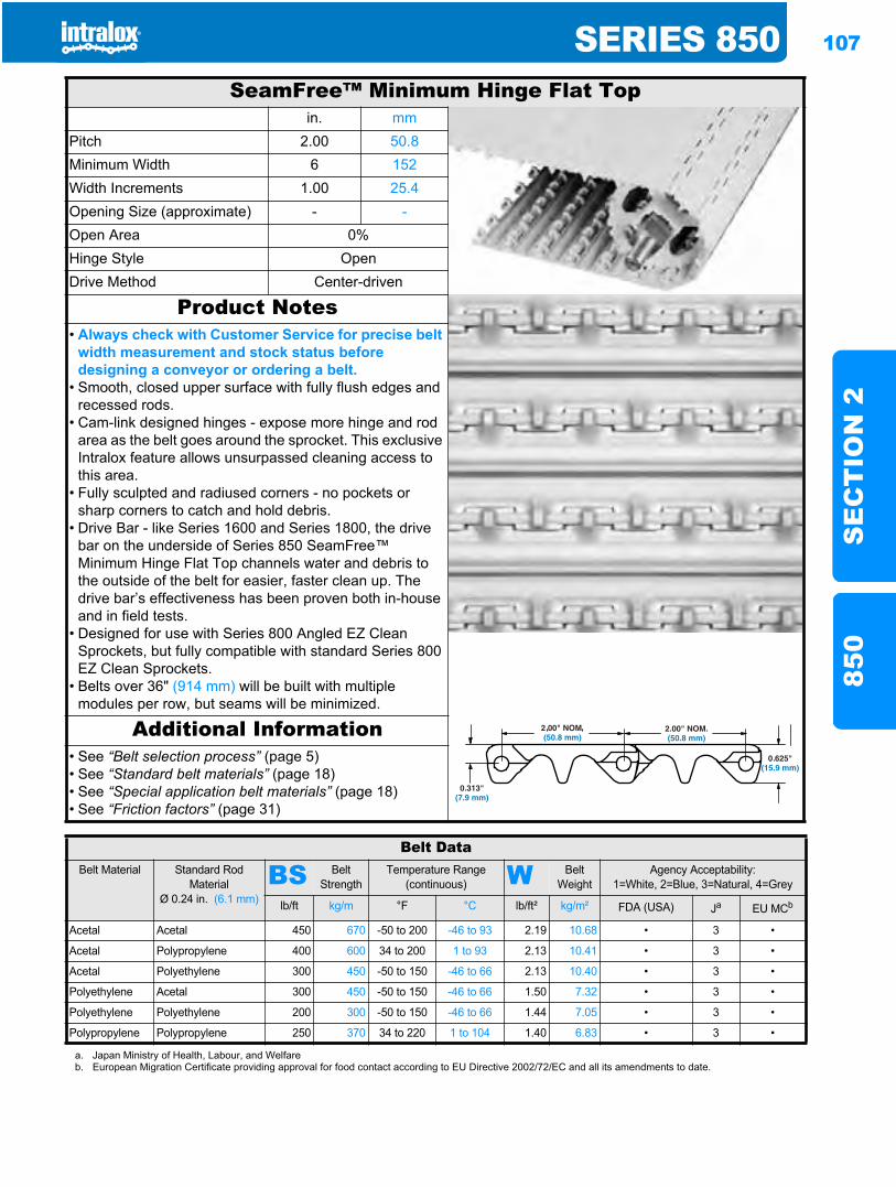
SERIES 850 107
SE
CT
ION
285
0
Series 850850
SeamFree™ Minimum Hinge Flat Topin. mm
Pitch 2.00 50.8Minimum Width 6 152Width Increments 1.00 25.4Opening Size (approximate) - -Open Area 0%Hinge Style OpenDrive Method Center-driven
Product Notes• Always check with Customer Service for precise belt
width measurement and stock status before designing a conveyor or ordering a belt.
• Smooth, closed upper surface with fully flush edges and recessed rods.
• Cam-link designed hinges - expose more hinge and rod area as the belt goes around the sprocket. This exclusive Intralox feature allows unsurpassed cleaning access to this area.
• Fully sculpted and radiused corners - no pockets or sharp corners to catch and hold debris.
• Drive Bar - like Series 1600 and Series 1800, the drive bar on the underside of Series 850 SeamFree™ Minimum Hinge Flat Top channels water and debris to the outside of the belt for easier, faster clean up. The drive bar’s effectiveness has been proven both in-house and in field tests.
• Designed for use with Series 800 Angled EZ Clean Sprockets, but fully compatible with standard Series 800 EZ Clean Sprockets.
• Belts over 36" (914 mm) will be built with multiple modules per row, but seams will be minimized.
Additional Information• See “Belt selection process” (page 5)• See “Standard belt materials” (page 18)• See “Special application belt materials” (page 18)• See “Friction factors” (page 31)
Belt DataBelt Material Standard Rod
MaterialØ 0.24 in. (6.1 mm)
BS Belt Strength
Temperature Range (continuous) W Belt
WeightAgency Acceptability:
1=White, 2=Blue, 3=Natural, 4=Grey
lb/ft kg/m °F °C lb/ft² kg/m² FDA (USA) Ja EU MCb
Acetal Acetal 450 670 -50 to 200 -46 to 93 2.19 10.68 • 3 •
Acetal Polypropylene 400 600 34 to 200 1 to 93 2.13 10.41 • 3 •
Acetal Polyethylene 300 450 -50 to 150 -46 to 66 2.13 10.40 • 3 •
Polyethylene Acetal 300 450 -50 to 150 -46 to 66 1.50 7.32 • 3 •
Polyethylene Polyethylene 200 300 -50 to 150 -46 to 66 1.44 7.05 • 3 •
Polypropylene Polypropylene 250 370 34 to 220 1 to 104 1.40 6.83 • 3 •
a. Japan Ministry of Health, Labour, and Welfareb. European Migration Certificate providing approval for food contact according to EU Directive 2002/72/EC and all its amendments to date.
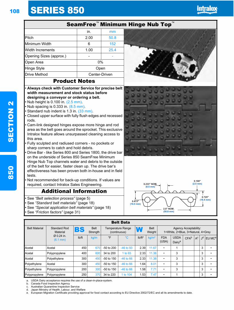
108 SERIES 850S
EC
TIO
N 2
850
SeamFree™ Minimum Hinge Nub Top™
in. mmPitch 2.00 50.8Minimum Width 6 152Width Increments 1.00 25.4Opening Sizes (approx.) - -Open Area 0%Hinge Style OpenDrive Method Center-Driven
Product Notes• Always check with Customer Service for precise belt
width measurement and stock status before designing a conveyor or ordering a belt.
• Nub height is 0.100 in. (2.5 mm).• Nub spacing is 0.333 in. (8.5 mm).• Standard nub indent is 1.3 in. (33 mm).• Closed upper surface with fully flush edges and recessed
rods.• Cam-link designed hinges expose more hinge and rod
area as the belt goes around the sprocket. This exclusive Intralox feature allows unsurpassed cleaning access to this area.
• Fully sculpted and radiused corners - no pockets or sharp corners to catch and hold debris.
• Drive Bar - like Series 800 and Series 1800, the drive bar on the underside of Series 850 SeamFree Minimum Hinge Nub Top channels water and debris to the outside of the belt for easier, faster clean up. The drive bar’s effectiveness has been proven both in-house and in field tests.
• Not recommended for back-up conditions. If values are required, contact Intralox Sales Engineering.
Additional Information• See “Belt selection process” (page 5)• See “Standard belt materials” (page 18)• See “Special application belt materials” (page 18)• See “Friction factors” (page 31)
Belt DataBelt Material Standard Rod
MaterialØ 0.24 in. (6.1 mm)
BS Belt Strength
Temperature Range (continuous) W Belt
WeightAgency Acceptability:
1=White, 2=Blue, 3=Natural, 4=Grey
lb/ft kg/m °F °C lb/ft² kg/m² FDA (USA)
USDADairya
CFAb Ac Jd EU MCe
Acetal Acetal 450 670 -50 to 200 -46 to 93 2.39 11.67 • 1 3 •
Acetal Polypropylene 400 600 34 to 200 1 to 93 2.33 11.38 • 3 3 •
Acetal Polyethylene 300 450 -50 to 150 -46 to 66 2.33 11.38 • 3 3 •
Polyethylene Acetal 300 450 -50 to 150 -46 to 66 1.64 8.01 • 3 3 •
Polyethylene Polypropylene 200 300 -50 to 150 -46 to 66 1.58 7.71 • 3 3 •
Polypropylene Polypropylene 250 370 34 to 220 1 to 104 1.53 7.47 • 1 3 •
a. USDA Dairy acceptance requires the use of a clean-in-place-system.b. Canada Food Inspection Agencyc. Australian Quarantine Inspection Serviced. Japan Ministry of Health, Labour, and Welfaree. European Migration Certificate providing approval for food contact according to EU Directive 2002/72/EC and all its amendments to date.
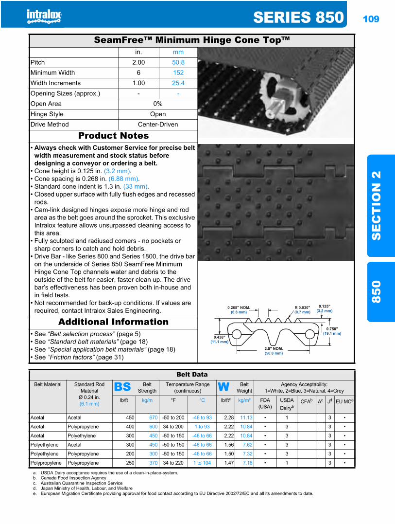
SERIES 850 109
SE
CT
ION
285
0
SeamFree™ Minimum Hinge Cone Top™in. mm
Pitch 2.00 50.8Minimum Width 6 152Width Increments 1.00 25.4Opening Sizes (approx.) - -Open Area 0%Hinge Style OpenDrive Method Center-Driven
Product Notes• Always check with Customer Service for precise belt
width measurement and stock status before designing a conveyor or ordering a belt.
• Cone height is 0.125 in. (3.2 mm).• Cone spacing is 0.268 in. (6.88 mm).• Standard cone indent is 1.3 in. (33 mm).• Closed upper surface with fully flush edges and recessed
rods.• Cam-link designed hinges expose more hinge and rod
area as the belt goes around the sprocket. This exclusive Intralox feature allows unsurpassed cleaning access to this area.
• Fully sculpted and radiused corners - no pockets or sharp corners to catch and hold debris.
• Drive Bar - like Series 800 and Series 1800, the drive bar on the underside of Series 850 SeamFree Minimum Hinge Cone Top channels water and debris to the outside of the belt for easier, faster clean up. The drive bar’s effectiveness has been proven both in-house and in field tests.
• Not recommended for back-up conditions. If values are required, contact Intralox Sales Engineering.
Additional Information• See “Belt selection process” (page 5)• See “Standard belt materials” (page 18)• See “Special application belt materials” (page 18)• See “Friction factors” (page 31)
Belt DataBelt Material Standard Rod
MaterialØ 0.24 in. (6.1 mm)
BS Belt Strength
Temperature Range (continuous) W Belt
WeightAgency Acceptability:
1=White, 2=Blue, 3=Natural, 4=Grey
lb/ft kg/m °F °C lb/ft² kg/m² FDA (USA)
USDADairya
CFAb Ac Jd EU MCe
Acetal Acetal 450 670 -50 to 200 -46 to 93 2.28 11.13 • 1 3 •
Acetal Polypropylene 400 600 34 to 200 1 to 93 2.22 10.84 • 3 3 •
Acetal Polyethylene 300 450 -50 to 150 -46 to 66 2.22 10.84 • 3 3 •
Polyethylene Acetal 300 450 -50 to 150 -46 to 66 1.56 7.62 • 3 3 •
Polyethylene Polypropylene 200 300 -50 to 150 -46 to 66 1.50 7.32 • 3 3 •
Polypropylene Polypropylene 250 370 34 to 220 1 to 104 1.47 7.18 • 1 3 •
a. USDA Dairy acceptance requires the use of a clean-in-place-system.b. Canada Food Inspection Agencyc. Australian Quarantine Inspection Serviced. Japan Ministry of Health, Labour, and Welfaree. European Migration Certificate providing approval for food contact according to EU Directive 2002/72/EC and all its amendments to date.
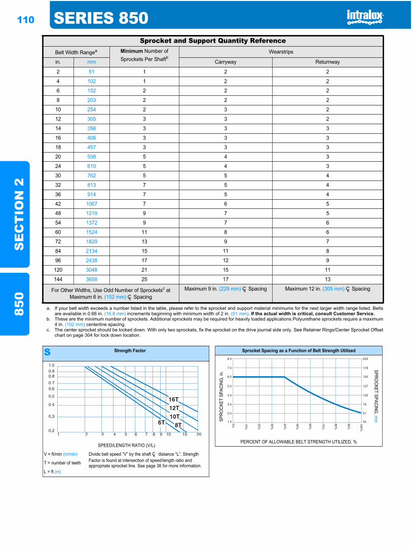
110 SERIES 850S
EC
TIO
N 2
850
Sprocket and Support Quantity ReferenceBelt Width Rangea Minimum Number of
Sprockets Per ShaftbWearstrips
in. mm Carryway Returnway
2 51 1 2 2
4 102 1 2 2
6 152 2 2 2
8 203 2 2 2
10 254 2 3 2
12 305 3 3 2
14 356 3 3 3
16 406 3 3 3
18 457 3 3 3
20 508 5 4 3
24 610 5 4 3
30 762 5 5 4
32 813 7 5 4
36 914 7 5 4
42 1067 7 6 5
48 1219 9 7 5
54 1372 9 7 6
60 1524 11 8 6
72 1829 13 9 7
84 2134 15 11 8
96 2438 17 12 9
120 3048 21 15 11
144 3658 25 17 13
For Other Widths, Use Odd Number of Sprocketsc at Maximum 6 in. (152 mm) CL Spacing
Maximum 9 in. (229 mm) CL Spacing Maximum 12 in. (305 mm) CL Spacing
a. If your belt width exceeds a number listed in the table, please refer to the sprocket and support material minimums for the next larger width range listed. Beltsare available in 0.66 in. (16.8 mm) increments beginning with minimum width of 2 in. (51 mm). If the actual width is critical, consult Customer Service.
b. These are the minimum number of sprockets. Additional sprockets may be required for heavily loaded applications.Polyurethane sprockets require a maximum4 in. (102 mm) centerline spacing.
c. The center sprocket should be locked down. With only two sprockets, fix the sprocket on the drive journal side only. See Retainer Rings/Center Sprocket Offsetchart on page 304 for lock down location.
S Strength Factor
SPEED/LENGTH RATIO (V/L)
V = ft/min (m/min) Divide belt speed “V” by the shaft CL distance “L”. Strength Factor is found at intersection of speed/length ratio and appropriate sprocket line. See page 36 for more information.T = number of teeth
L = ft (m)
Sprocket Spacing as a Function of Belt Strength Utilized
SPRO
CKET
SPA
CING
, in.
SPROCKET SPACING
, mm
PERCENT OF ALLOWABLE BELT STRENGTH UTILIZED, %
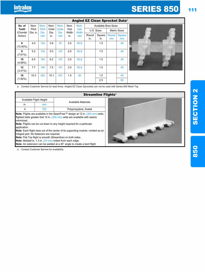
SERIES 850 111
SE
CT
ION
285
0
Angled EZ Clean Sprocket Dataa
No. of Teeth
(Chordal Action)
Nom. Pitch
Dia. in.
Nom. Pitch Dia. mm
Nom. Outer Dia.in.
Nom. Outer Dia.mm
Nom. Hub
Width in.
Nom. Hub
Width mm
Available Bore Sizes
U.S. Sizes Metric Sizes
Round in.
Square in.
Round mm
Square mm
6(13.40%)
4.0 102 3.8 97 2.0 50.8 1.5 40
8(7.61%)
5.2 132 5.0 127 2.0 50.8 1.5 40
10(4.89%)
6.5 165 6.2 157 2.0 50.8 1.5 40
12(3.41%)
7.7 196 7.5 191 2.0 50.8 1.5 40
16(1.92%)
10.3 262 10.1 257 1.5 38 1.5 40
2.5 60
a. Contact Customer Service for lead times. Angled EZ Clean Sprockets can not be used with Series 800 Mesh Top
Streamline Flightsa
Available Flight HeightAvailable Materials
in. mm
4 102 Polypropylene, Acetal
Note: Flights are available in the SeamFree™ design at 12 in. (304 mm) wide; flighted belts greater that 12 in. (304 mm) wide are available with seams minimized.Note: Flights can be cut down to any height required for a particular application.Note: Each flight rises out of the center of its supporting module, molded as an integral part. No fasteners are required.Note: Flat Top flight is smooth (Streamline) on both sides.Note: Molded-in, 1.3 in. (33 mm) indent from each edge.Note: An extension can be welded at a 45° angle to create a bent flight.
a. Contact Customer Service for availability.
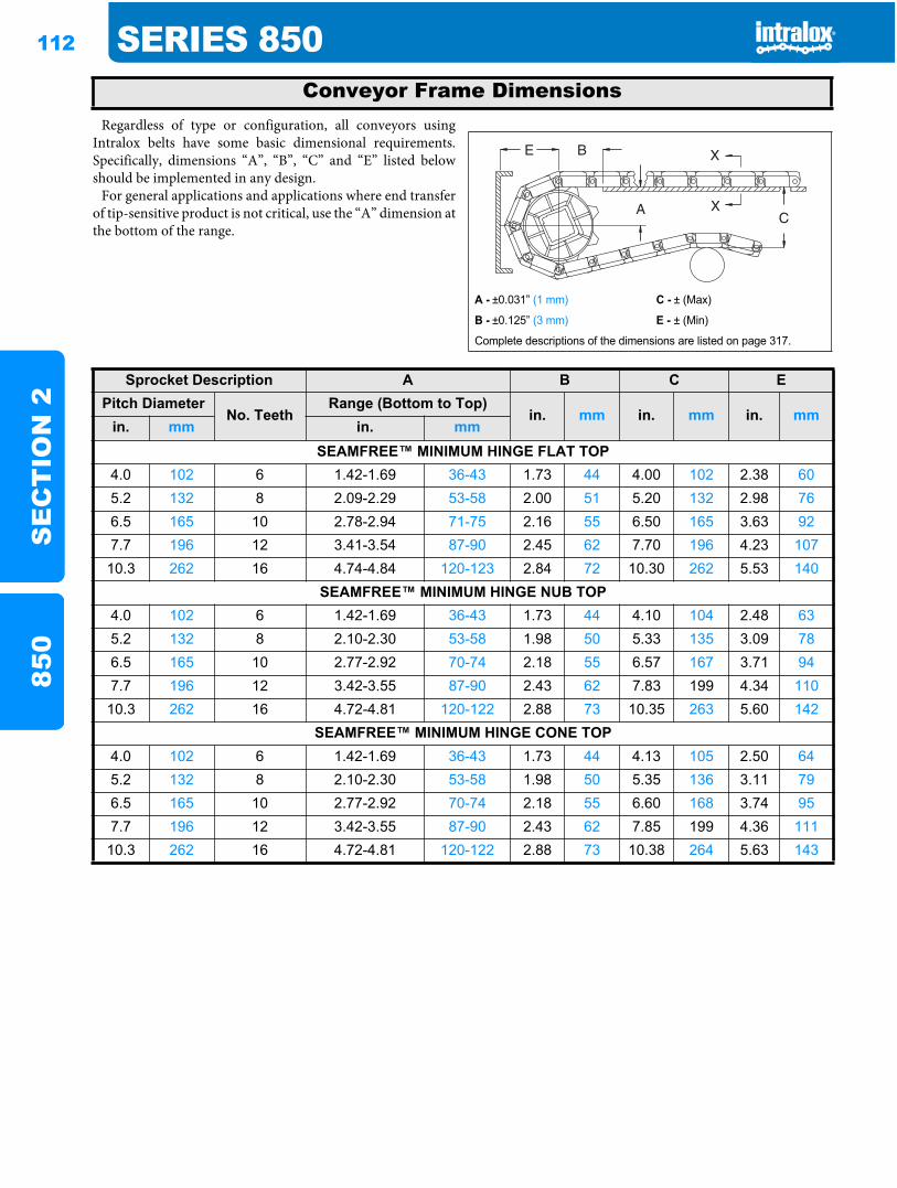
112 SERIES 850S
EC
TIO
N 2
850
Regardless of type or configuration, all conveyors usingIntralox belts have some basic dimensional requirements.Specifically, dimensions “A”, “B”, “C” and “E” listed belowshould be implemented in any design.
For general applications and applications where end transferof tip-sensitive product is not critical, use the “A” dimension atthe bottom of the range.
Conveyor Frame Dimensions
A - ±0.031” (1 mm) C - ± (Max)
B - ±0.125” (3 mm) E - ± (Min)
Complete descriptions of the dimensions are listed on page 317.
Sprocket Description A B C EPitch Diameter
No. TeethRange (Bottom to Top)
in. mm in. mm in. mmin. mm in. mm
SEAMFREE™ MINIMUM HINGE FLAT TOP4.0 102 6 1.42-1.69 36-43 1.73 44 4.00 102 2.38 605.2 132 8 2.09-2.29 53-58 2.00 51 5.20 132 2.98 766.5 165 10 2.78-2.94 71-75 2.16 55 6.50 165 3.63 927.7 196 12 3.41-3.54 87-90 2.45 62 7.70 196 4.23 10710.3 262 16 4.74-4.84 120-123 2.84 72 10.30 262 5.53 140
SEAMFREE™ MINIMUM HINGE NUB TOP4.0 102 6 1.42-1.69 36-43 1.73 44 4.10 104 2.48 635.2 132 8 2.10-2.30 53-58 1.98 50 5.33 135 3.09 786.5 165 10 2.77-2.92 70-74 2.18 55 6.57 167 3.71 947.7 196 12 3.42-3.55 87-90 2.43 62 7.83 199 4.34 11010.3 262 16 4.72-4.81 120-122 2.88 73 10.35 263 5.60 142
SEAMFREE™ MINIMUM HINGE CONE TOP4.0 102 6 1.42-1.69 36-43 1.73 44 4.13 105 2.50 645.2 132 8 2.10-2.30 53-58 1.98 50 5.35 136 3.11 796.5 165 10 2.77-2.92 70-74 2.18 55 6.60 168 3.74 957.7 196 12 3.42-3.55 87-90 2.43 62 7.85 199 4.36 11110.3 262 16 4.72-4.81 120-122 2.88 73 10.38 264 5.63 143
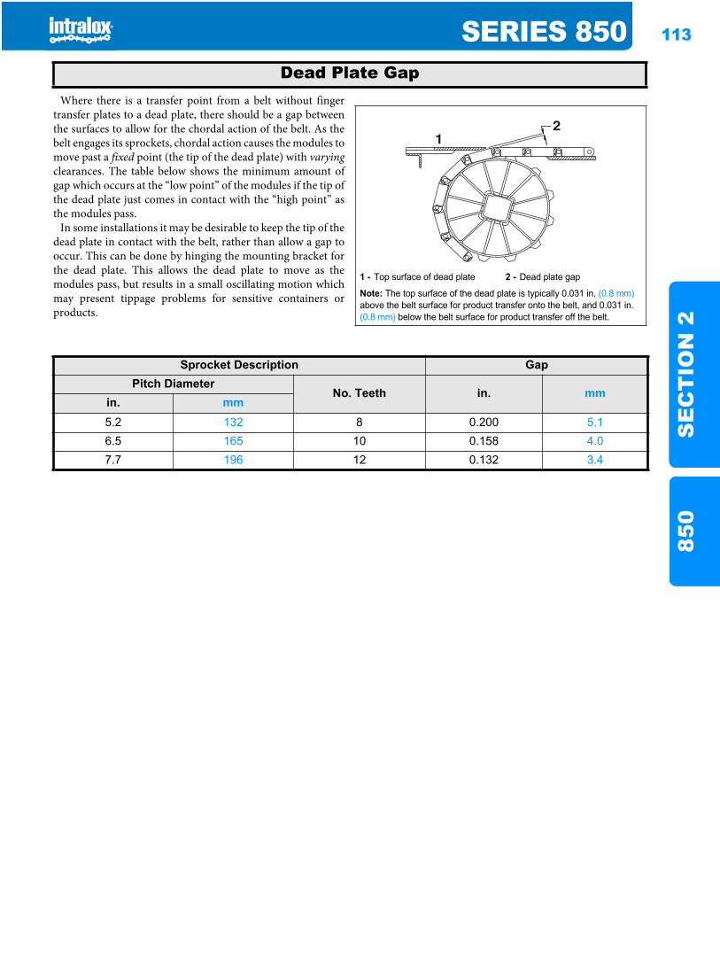
SERIES 850 113
SE
CT
ION
285
0
Where there is a transfer point from a belt without fingertransfer plates to a dead plate, there should be a gap betweenthe surfaces to allow for the chordal action of the belt. As thebelt engages its sprockets, chordal action causes the modules tomove past a fixed point (the tip of the dead plate) with varyingclearances. The table below shows the minimum amount ofgap which occurs at the “low point” of the modules if the tip ofthe dead plate just comes in contact with the “high point” asthe modules pass.
In some installations it may be desirable to keep the tip of thedead plate in contact with the belt, rather than allow a gap tooccur. This can be done by hinging the mounting bracket forthe dead plate. This allows the dead plate to move as themodules pass, but results in a small oscillating motion whichmay present tippage problems for sensitive containers orproducts.
Dead Plate Gap
1 - Top surface of dead plate 2 - Dead plate gap
Note: The top surface of the dead plate is typically 0.031 in. (0.8 mm)above the belt surface for product transfer onto the belt, and 0.031 in. (0.8 mm) below the belt surface for product transfer off the belt.
21
Sprocket Description GapPitch Diameter
No. Teeth in. mmin. mm5.2 132 8 0.200 5.16.5 165 10 0.158 4.07.7 196 12 0.132 3.4

114 SERIES 850S
EC
TIO
N 2
850
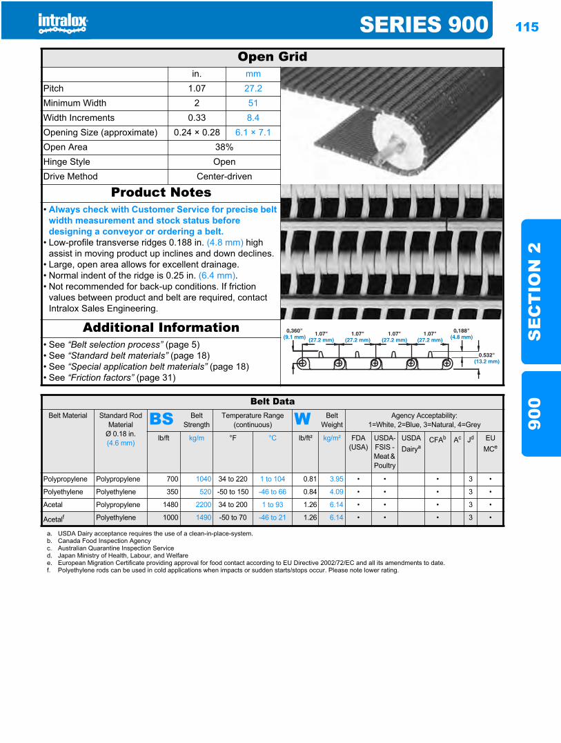
SERIES 900 115
SE
CT
ION
290
0
Series 900900
Open Gridin. mm
Pitch 1.07 27.2Minimum Width 2 51Width Increments 0.33 8.4Opening Size (approximate) 0.24 × 0.28 6.1 × 7.1Open Area 38%Hinge Style OpenDrive Method Center-driven
Product Notes• Always check with Customer Service for precise belt
width measurement and stock status before designing a conveyor or ordering a belt.
• Low-profile transverse ridges 0.188 in. (4.8 mm) high assist in moving product up inclines and down declines.
• Large, open area allows for excellent drainage.• Normal indent of the ridge is 0.25 in. (6.4 mm).• Not recommended for back-up conditions. If friction
values between product and belt are required, contact Intralox Sales Engineering.
Additional Information• See “Belt selection process” (page 5)• See “Standard belt materials” (page 18)• See “Special application belt materials” (page 18)• See “Friction factors” (page 31)
Belt DataBelt Material Standard Rod
MaterialØ 0.18 in. (4.6 mm)
BS Belt Strength
Temperature Range (continuous) W Belt
WeightAgency Acceptability:
1=White, 2=Blue, 3=Natural, 4=Grey
lb/ft kg/m °F °C lb/ft² kg/m² FDA(USA)
USDA-FSIS - Meat & Poultry
USDADairya
CFAb Ac Jd EU MCe
Polypropylene Polypropylene 700 1040 34 to 220 1 to 104 0.81 3.95 • • • 3 •
Polyethylene Polyethylene 350 520 -50 to 150 -46 to 66 0.84 4.09 • • • 3 •
Acetal Polypropylene 1480 2200 34 to 200 1 to 93 1.26 6.14 • • • 3 •
Acetalf Polyethylene 1000 1490 -50 to 70 -46 to 21 1.26 6.14 • • • 3 •
a. USDA Dairy acceptance requires the use of a clean-in-place-system.b. Canada Food Inspection Agencyc. Australian Quarantine Inspection Serviced. Japan Ministry of Health, Labour, and Welfaree. European Migration Certificate providing approval for food contact according to EU Directive 2002/72/EC and all its amendments to date.f. Polyethylene rods can be used in cold applications when impacts or sudden starts/stops occur. Please note lower rating.
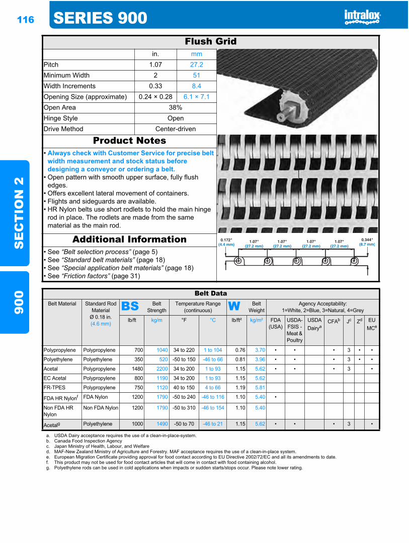
116 SERIES 900S
EC
TIO
N 2
900
Flush Gridin. mm
Pitch 1.07 27.2Minimum Width 2 51Width Increments 0.33 8.4Opening Size (approximate) 0.24 × 0.28 6.1 × 7.1Open Area 38%Hinge Style OpenDrive Method Center-driven
Product Notes• Always check with Customer Service for precise belt
width measurement and stock status before designing a conveyor or ordering a belt.
• Open pattern with smooth upper surface, fully flush edges.
• Offers excellent lateral movement of containers.• Flights and sideguards are available.• HR Nylon belts use short rodlets to hold the main hinge
rod in place. The rodlets are made from the same material as the main rod.
Additional Information• See “Belt selection process” (page 5)• See “Standard belt materials” (page 18)• See “Special application belt materials” (page 18)• See “Friction factors” (page 31)
Belt DataBelt Material Standard Rod
MaterialØ 0.18 in. (4.6 mm)
BS Belt Strength
Temperature Range (continuous) W Belt
WeightAgency Acceptability:
1=White, 2=Blue, 3=Natural, 4=Grey
lb/ft kg/m °F °C lb/ft² kg/m² FDA(USA)
USDA-FSIS - Meat & Poultry
USDADairya
CFAb Jc Zd EUMCe
Polypropylene Polypropylene 700 1040 34 to 220 1 to 104 0.76 3.70 • • • 3 • •
Polyethylene Polyethylene 350 520 -50 to 150 -46 to 66 0.81 3.96 • • • 3 • •
Acetal Polypropylene 1480 2200 34 to 200 1 to 93 1.15 5.62 • • • 3 •
EC Acetal Polypropylene 800 1190 34 to 200 1 to 93 1.15 5.62
FR-TPES Polypropylene 750 1120 40 to 150 4 to 66 1.19 5.81
FDA HR Nylonf FDA Nylon 1200 1790 -50 to 240 -46 to 116 1.10 5.40 •
Non FDA HR Nylon
Non FDA Nylon 1200 1790 -50 to 310 -46 to 154 1.10 5.40
Acetalg Polyethylene 1000 1490 -50 to 70 -46 to 21 1.15 5.62 • • • 3 •
a. USDA Dairy acceptance requires the use of a clean-in-place-system.b. Canada Food Inspection Agencyc. Japan Ministry of Health, Labour, and Welfared. MAF-New Zealand Ministry of Agriculture and Forestry. MAF acceptance requires the use of a clean-in-place system.e. European Migration Certificate providing approval for food contact according to EU Directive 2002/72/EC and all its amendments to date.f. This product may not be used for food contact articles that will come in contact with food containing alcohol.g. Polyethylene rods can be used in cold applications when impacts or sudden starts/stops occur. Please note lower rating.
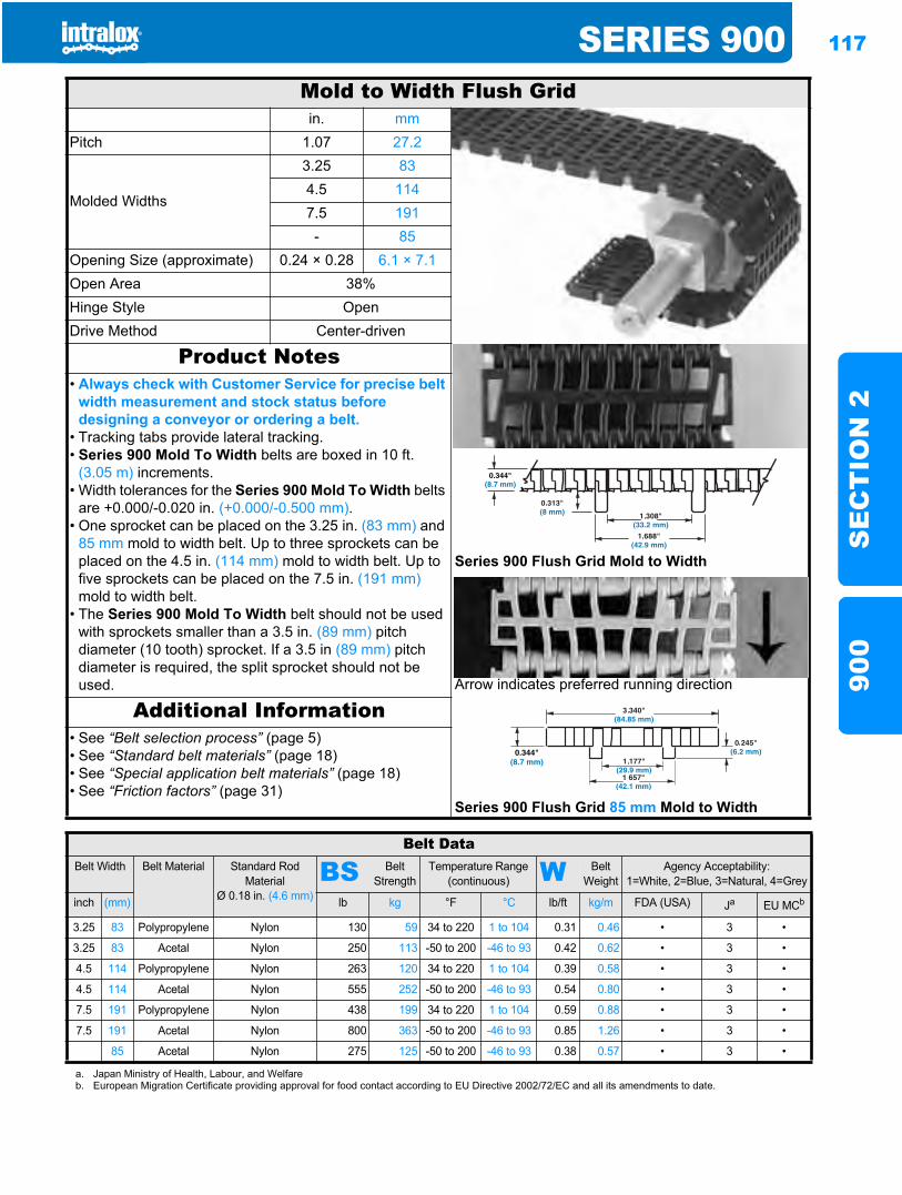
SERIES 900 117
SE
CT
ION
290
0
Mold to Width Flush Gridin. mm
Pitch 1.07 27.2
Molded Widths
3.25 834.5 1147.5 191- 85
Opening Size (approximate) 0.24 × 0.28 6.1 × 7.1Open Area 38%Hinge Style OpenDrive Method Center-driven
Product Notes
Series 900 Flush Grid Mold to Width
Arrow indicates preferred running direction
Series 900 Flush Grid 85 mm Mold to Width
• Always check with Customer Service for precise belt width measurement and stock status before designing a conveyor or ordering a belt.
• Tracking tabs provide lateral tracking.• Series 900 Mold To Width belts are boxed in 10 ft.
(3.05 m) increments.• Width tolerances for the Series 900 Mold To Width belts
are +0.000/-0.020 in. (+0.000/-0.500 mm).• One sprocket can be placed on the 3.25 in. (83 mm) and
85 mm mold to width belt. Up to three sprockets can be placed on the 4.5 in. (114 mm) mold to width belt. Up to five sprockets can be placed on the 7.5 in. (191 mm)mold to width belt.
• The Series 900 Mold To Width belt should not be used with sprockets smaller than a 3.5 in. (89 mm) pitch diameter (10 tooth) sprocket. If a 3.5 in (89 mm) pitch diameter is required, the split sprocket should not be used.
Additional Information• See “Belt selection process” (page 5)• See “Standard belt materials” (page 18)• See “Special application belt materials” (page 18)• See “Friction factors” (page 31)
Belt DataBelt Width Belt Material Standard Rod
MaterialØ 0.18 in. (4.6 mm)
BS Belt Strength
Temperature Range (continuous) W Belt
WeightAgency Acceptability:
1=White, 2=Blue, 3=Natural, 4=Grey
inch (mm) lb kg °F °C lb/ft kg/m FDA (USA) Ja EU MCb
3.25 83 Polypropylene Nylon 130 59 34 to 220 1 to 104 0.31 0.46 • 3 •
3.25 83 Acetal Nylon 250 113 -50 to 200 -46 to 93 0.42 0.62 • 3 •
4.5 114 Polypropylene Nylon 263 120 34 to 220 1 to 104 0.39 0.58 • 3 •
4.5 114 Acetal Nylon 555 252 -50 to 200 -46 to 93 0.54 0.80 • 3 •
7.5 191 Polypropylene Nylon 438 199 34 to 220 1 to 104 0.59 0.88 • 3 •
7.5 191 Acetal Nylon 800 363 -50 to 200 -46 to 93 0.85 1.26 • 3 •
85 Acetal Nylon 275 125 -50 to 200 -46 to 93 0.38 0.57 • 3 •
a. Japan Ministry of Health, Labour, and Welfareb. European Migration Certificate providing approval for food contact according to EU Directive 2002/72/EC and all its amendments to date.
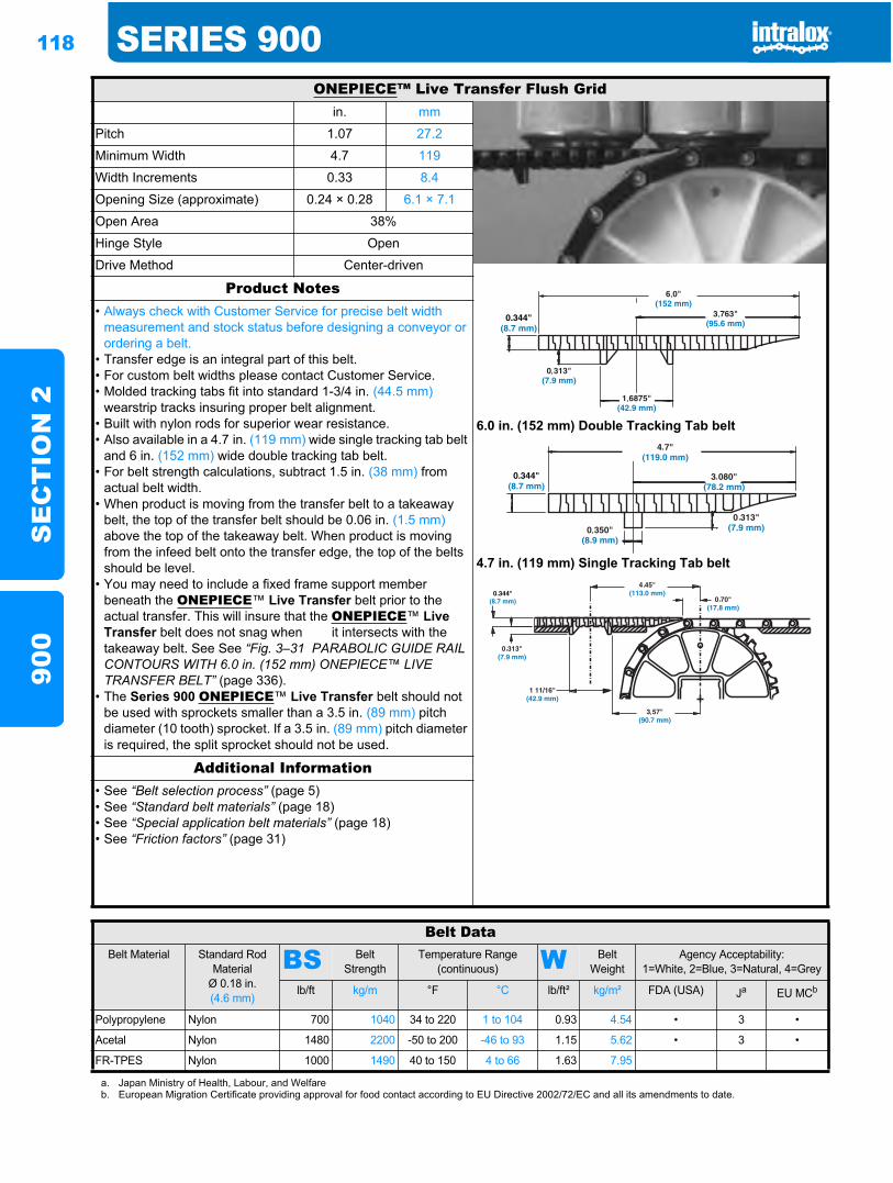
118 SERIES 900S
EC
TIO
N 2
900
ONEPIECE™ Live Transfer Flush Gridin. mm
Pitch 1.07 27.2
Minimum Width 4.7 119
Width Increments 0.33 8.4
Opening Size (approximate) 0.24 × 0.28 6.1 × 7.1
Open Area 38%
Hinge Style Open
Drive Method Center-driven
Product Notes
6.0 in. (152 mm) Double Tracking Tab belt
4.7 in. (119 mm) Single Tracking Tab belt
• Always check with Customer Service for precise belt width measurement and stock status before designing a conveyor or ordering a belt.
• Transfer edge is an integral part of this belt.• For custom belt widths please contact Customer Service.• Molded tracking tabs fit into standard 1-3/4 in. (44.5 mm)
wearstrip tracks insuring proper belt alignment.• Built with nylon rods for superior wear resistance.• Also available in a 4.7 in. (119 mm) wide single tracking tab belt
and 6 in. (152 mm) wide double tracking tab belt.• For belt strength calculations, subtract 1.5 in. (38 mm) from
actual belt width.• When product is moving from the transfer belt to a takeaway
belt, the top of the transfer belt should be 0.06 in. (1.5 mm)above the top of the takeaway belt. When product is moving from the infeed belt onto the transfer edge, the top of the belts should be level.
• You may need to include a fixed frame support member beneath the ONEPIECE™ Live Transfer belt prior to the actual transfer. This will insure that the ONEPIECE™ LiveTransfer belt does not snag when it intersects with the takeaway belt. See See “Fig. 3–31 PARABOLIC GUIDE RAIL CONTOURS WITH 6.0 in. (152 mm) ONEPIECE™ LIVE TRANSFER BELT” (page 336).
• The Series 900 ONEPIECE™ Live Transfer belt should not be used with sprockets smaller than a 3.5 in. (89 mm) pitch diameter (10 tooth) sprocket. If a 3.5 in. (89 mm) pitch diameter is required, the split sprocket should not be used.
Additional Information• See “Belt selection process” (page 5)• See “Standard belt materials” (page 18)• See “Special application belt materials” (page 18)• See “Friction factors” (page 31)
Belt DataBelt Material Standard Rod
MaterialØ 0.18 in. (4.6 mm)
BS Belt Strength
Temperature Range (continuous) W Belt
WeightAgency Acceptability:
1=White, 2=Blue, 3=Natural, 4=Grey
lb/ft kg/m °F °C lb/ft² kg/m² FDA (USA) Ja EU MCb
Polypropylene Nylon 700 1040 34 to 220 1 to 104 0.93 4.54 • 3 •
Acetal Nylon 1480 2200 -50 to 200 -46 to 93 1.15 5.62 • 3 •
FR-TPES Nylon 1000 1490 40 to 150 4 to 66 1.63 7.95
a. Japan Ministry of Health, Labour, and Welfareb. European Migration Certificate providing approval for food contact according to EU Directive 2002/72/EC and all its amendments to date.
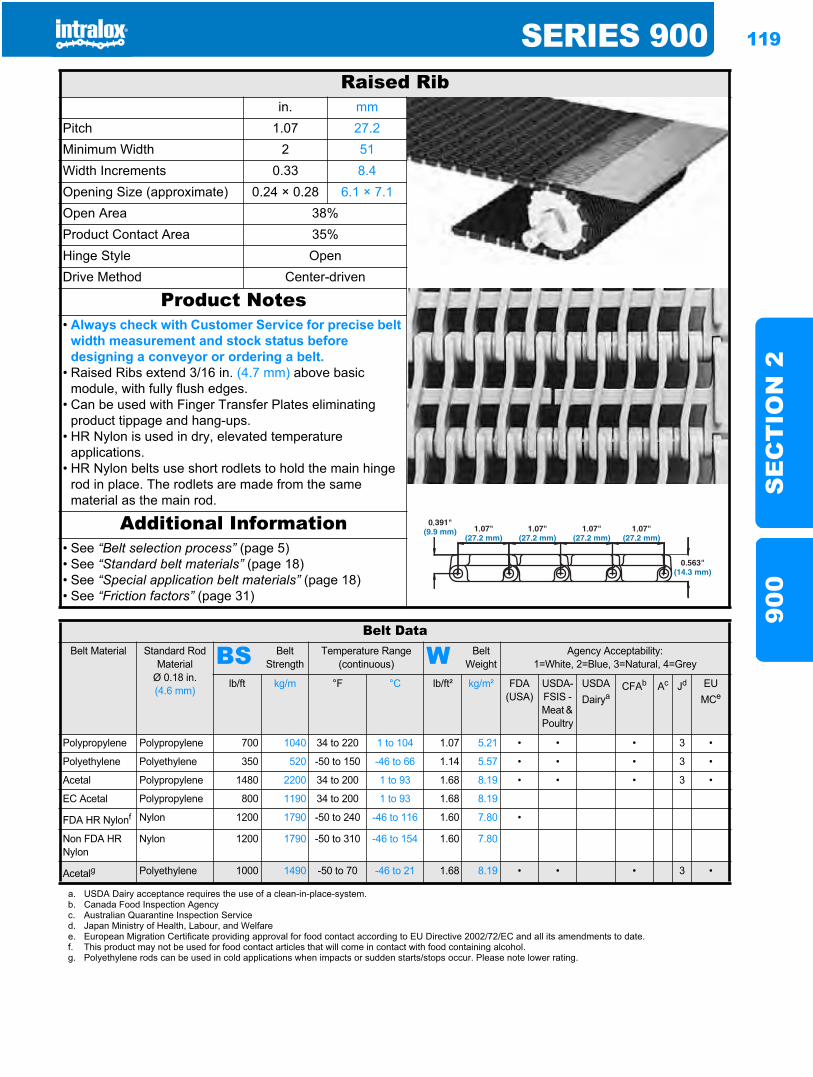
SERIES 900 119
SE
CT
ION
290
0
Raised Ribin. mm
Pitch 1.07 27.2Minimum Width 2 51Width Increments 0.33 8.4Opening Size (approximate) 0.24 × 0.28 6.1 × 7.1Open Area 38%Product Contact Area 35%Hinge Style OpenDrive Method Center-driven
Product Notes• Always check with Customer Service for precise belt
width measurement and stock status before designing a conveyor or ordering a belt.
• Raised Ribs extend 3/16 in. (4.7 mm) above basic module, with fully flush edges.
• Can be used with Finger Transfer Plates eliminating product tippage and hang-ups.
• HR Nylon is used in dry, elevated temperature applications.
• HR Nylon belts use short rodlets to hold the main hinge rod in place. The rodlets are made from the same material as the main rod.
Additional Information• See “Belt selection process” (page 5)• See “Standard belt materials” (page 18)• See “Special application belt materials” (page 18)• See “Friction factors” (page 31)
Belt DataBelt Material Standard Rod
MaterialØ 0.18 in. (4.6 mm)
BS Belt Strength
Temperature Range (continuous) W Belt
WeightAgency Acceptability:
1=White, 2=Blue, 3=Natural, 4=Grey
lb/ft kg/m °F °C lb/ft² kg/m² FDA(USA)
USDA-FSIS - Meat & Poultry
USDADairya
CFAb Ac Jd EU MCe
Polypropylene Polypropylene 700 1040 34 to 220 1 to 104 1.07 5.21 • • • 3 •
Polyethylene Polyethylene 350 520 -50 to 150 -46 to 66 1.14 5.57 • • • 3 •
Acetal Polypropylene 1480 2200 34 to 200 1 to 93 1.68 8.19 • • • 3 •
EC Acetal Polypropylene 800 1190 34 to 200 1 to 93 1.68 8.19
FDA HR Nylonf Nylon 1200 1790 -50 to 240 -46 to 116 1.60 7.80 •
Non FDA HR Nylon
Nylon 1200 1790 -50 to 310 -46 to 154 1.60 7.80
Acetalg Polyethylene 1000 1490 -50 to 70 -46 to 21 1.68 8.19 • • • 3 •
a. USDA Dairy acceptance requires the use of a clean-in-place-system.b. Canada Food Inspection Agencyc. Australian Quarantine Inspection Serviced. Japan Ministry of Health, Labour, and Welfaree. European Migration Certificate providing approval for food contact according to EU Directive 2002/72/EC and all its amendments to date.f. This product may not be used for food contact articles that will come in contact with food containing alcohol.g. Polyethylene rods can be used in cold applications when impacts or sudden starts/stops occur. Please note lower rating.
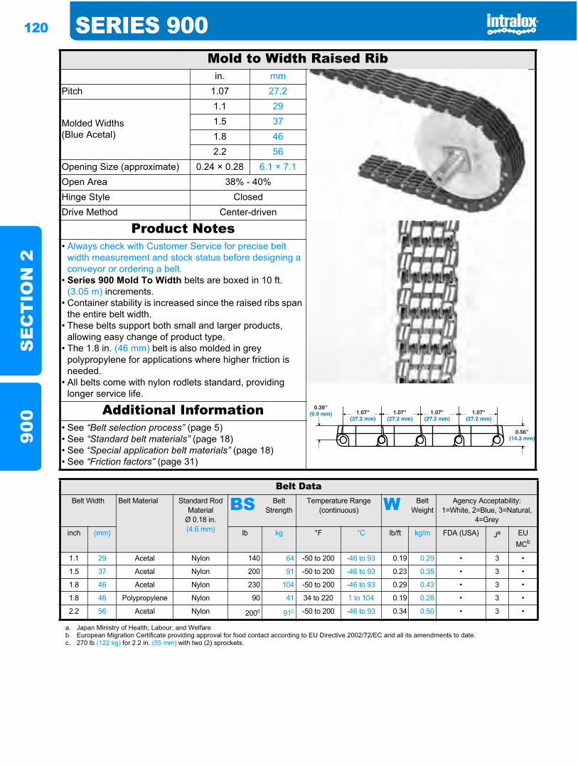
120 SERIES 900S
EC
TIO
N 2
900
Mold to Width Raised Ribin. mm
Pitch 1.07 27.2
Molded Widths(Blue Acetal)
1.1 291.5 371.8 462.2 56
Opening Size (approximate) 0.24 × 0.28 6.1 × 7.1Open Area 38% - 40%Hinge Style ClosedDrive Method Center-driven
Product Notes• Always check with Customer Service for precise belt
width measurement and stock status before designing a conveyor or ordering a belt.
• Series 900 Mold To Width belts are boxed in 10 ft. (3.05 m) increments.
• Container stability is increased since the raised ribs span the entire belt width.
• These belts support both small and larger products, allowing easy change of product type.
• The 1.8 in. (46 mm) belt is also molded in grey polypropylene for applications where higher friction is needed.
• All belts come with nylon rodlets standard, providing longer service life.
Additional Information• See “Belt selection process” (page 5)• See “Standard belt materials” (page 18)• See “Special application belt materials” (page 18)• See “Friction factors” (page 31)
Belt DataBelt Width Belt Material Standard Rod
MaterialØ 0.18 in. (4.6 mm)
BS Belt Strength
Temperature Range (continuous) W Belt
WeightAgency Acceptability:
1=White, 2=Blue, 3=Natural, 4=Grey
inch (mm) lb kg °F °C lb/ft kg/m FDA (USA) Ja EU MCb
1.1 29 Acetal Nylon 140 64 -50 to 200 -46 to 93 0.19 0.29 • 3 •
1.5 37 Acetal Nylon 200 91 -50 to 200 -46 to 93 0.23 0.35 • 3 •
1.8 46 Acetal Nylon 230 104 -50 to 200 -46 to 93 0.29 0.43 • 3 •
1.8 46 Polypropylene Nylon 90 41 34 to 220 1 to 104 0.19 0.28 • 3 •
2.2 56 Acetal Nylon 200c 91c -50 to 200 -46 to 93 0.34 0.50 • 3 •
a. Japan Ministry of Health, Labour, and Welfareb. European Migration Certificate providing approval for food contact according to EU Directive 2002/72/EC and all its amendments to date.c. 270 lb (122 kg) for 2.2 in. (55 mm) with two (2) sprockets.
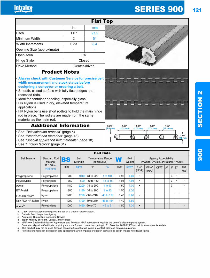
SERIES 900 121
SE
CT
ION
290
0
Flat Topin. mm
Pitch 1.07 27.2Minimum Width 2 51Width Increments 0.33 8.4Opening Size (approximate) - -Open Area 0%Hinge Style ClosedDrive Method Center-driven
Product Notes• Always check with Customer Service for precise belt
width measurement and stock status before designing a conveyor or ordering a belt.
• Smooth, closed surface with fully flush edges and recessed rods.
• Ideal for container handling, especially glass.• HR Nylon is used in dry, elevated temperature
applications.• HR Nylon belts use short rodlets to hold the main hinge
rod in place. The rodlets are made from the same material as the main rod.
Additional Information• See “Belt selection process” (page 5)• See “Standard belt materials” (page 18)• See “Special application belt materials” (page 18)• See “Friction factors” (page 31)
Belt DataBelt Material Standard Rod
MaterialØ 0.18 in. (4.6 mm)
BS Belt Strength
Temperature Range (continuous) W Belt
WeightAgency Acceptability:
1=White, 2=Blue, 3=Natural, 4=Grey
lb/ft kg/m °F °C lb/ft² kg/m² FDA (USA)
USDADairya
CFAb Ac Jd Ze EU MCf
Polypropylene Polypropylene 700 1040 34 to 220 1 to 104 0.96 4.69 • 3 • •
Polyethylene Polyethylene 350 520 -50 to 150 -46 to 66 1.01 4.95 • 3 • •
Acetal Polypropylene 1480 2200 34 to 200 1 to 93 1.50 7.30 • 3 •
EC Acetal Polypropylene 800 1190 34 to 200 1 to 93 1.50 7.30
FDA HR Nylong Nylon 1200 1790 -50 to 240 -46 to 116 1.40 6.80 •
Non FDA HR Nylon Nylon 1200 1790 -50 to 310 -46 to 154 1.40 6.80
Acetalh Polyethylene 1000 1490 -50 to 70 -46 to 21 1.50 7.30 • •
a. USDA Dairy acceptance requires the use of a clean-in-place-system.b. Canada Food Inspection Agencyc. Australian Quarantine Inspection Serviced. Japan Ministry of Health, Labour, and Welfaree. MAF-New Zealand Ministry of Agriculture and Forestry. MAF acceptance requires the use of a clean-in-place system.f. European Migration Certificate providing approval for food contact according to EU Directive 2002/72/EC and all its amendments to date.g. This product may not be used for food contact articles that will come in contact with food containing alcohol.h. Polyethylene rods can be used in cold applications when impacts or sudden starts/stops occur. Please note lower rating.
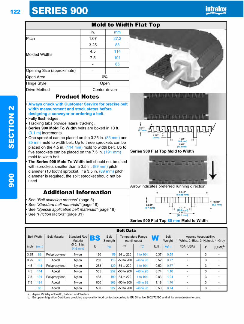
122 SERIES 900S
EC
TIO
N 2
900
Mold to Width Flat Topin. mm
Pitch 1.07 27.2
Molded Widths
3.25 834.5 1147.5 191- 85
Opening Size (approximate) - -Open Area 0%Hinge Style OpenDrive Method Center-driven
Product Notes
Series 900 Flat Top Mold to Width
Arrow indicates preferred running direction
• Always check with Customer Service for precise belt width measurement and stock status before designing a conveyor or ordering a belt.
• Fully flush edges• Tracking tabs provide lateral tracking.• Series 900 Mold To Width belts are boxed in 10 ft.
(3.1 m) increments.• One sprocket can be placed on the 3.25 in. (83 mm) and
85 mm mold to width belt. Up to three sprockets can be placed on the 4.5 in. (114 mm) mold to width belt. Up to five sprockets can be placed on the 7.5 in. (191 mm)mold to width belt.
• The Series 900 Mold To Width belt should not be used with sprockets smaller than a 3.5 in. (89 mm) pitch diameter (10 tooth) sprocket. If a 3.5 in. (89 mm) pitch diameter is required, the split sprocket should not be used.
Additional Information
Series 900 Flat Top 85 mm Mold to Width
• See “Belt selection process” (page 5)• See “Standard belt materials” (page 18)• See “Special application belt materials” (page 18)• See “Friction factors” (page 31)
Belt DataBelt Width Belt Material Standard Rod
MaterialØ 0.18 in. (4.6 mm)
BS Belt Strength
Temperature Range (continuous) W Belt
WeightAgency Acceptability:
1=White, 2=Blue, 3=Natural, 4=Grey
inch (mm) lb kg °F °C lb/ft kg/m FDA (USA) Ja EU MCb
3.25 83 Polypropylene Nylon 130 59 34 to 220 1 to 104 0.37 0.55 • 3 •
3.25 83 Acetal Nylon 250 113 -50 to 200 -46 to 93 0.52 0.77 • 3 •
4.5 114 Polypropylene Nylon 263 120 34 to 220 1 to 104 0.52 0.77 • 3 •
4.5 114 Acetal Nylon 555 252 -50 to 200 -46 to 93 0.74 1.10 • 3 •
7.5 191 Polypropylene Nylon 438 199 34 to 220 1 to 104 0.83 1.24 • 3 •
7.5 191 Acetal Nylon 800 363 -50 to 200 -46 to 93 1.18 1.76 • 3 •
85 Acetal Nylon 500 227 -50 to 200 -46 to 93 0.50 0.74 • 3 •
a. Japan Ministry of Health, Labour, and Welfareb. European Migration Certificate providing approval for food contact according to EU Directive 2002/72/EC and all its amendments to date.
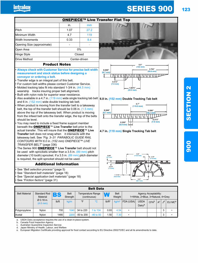
SERIES 900 123
SE
CT
ION
290
0
ONEPIECE™ Live Transfer Flat Topin. mm
Pitch 1.07 27.2
Minimum Width 4.7 119
Width Increments 0.33 8.4
Opening Size (approximate) - -
Open Area 0%
Hinge Style Closed
Drive Method Center-driven
Product Notes
6.0 in. (152 mm) Double Tracking Tab belt
4.7 in. (119 mm) Single Tracking Tab belt
• Always check with Customer Service for precise belt width measurement and stock status before designing a conveyor or ordering a belt.
• Transfer edge is an integral part of this belt.• For custom belt widths please contact Customer Service.• Molded tracking tabs fit into standard 1-3/4 in. (44.5 mm)
wearstrip tracks insuring proper belt alignment.• Built with nylon rods for superior wear resistance.• Also available in a 4.7 in. (119 mm) wide single tracking tab belt
and 6 in. (152 mm) wide double tracking tab belt.• When product is moving from the transfer belt to a takeaway
belt, the top of the transfer belt should be 0.06 in. (1.5 mm)above the top of the takeaway belt. When product is moving from the infeed belt onto the transfer edge, the top of the belts should be level.
• You may need to include a fixed frame support member beneath the ONEPIECE™ Live Transfer belt prior to the actual transfer. This will insure that the ONEPIECE™ LiveTransfer belt does not snag when it intersects with the takeaway belt. See “Fig. 3–31 PARABOLIC GUIDE RAIL CONTOURS WITH 6.0 in. (152 mm) ONEPIECE™ LIVE TRANSFER BELT” (page 336)
• The Series 900 ONEPIECE™ Live Transfer belt should not be used with sprockets smaller than a 3.5 in. (89 mm) pitch diameter (10 tooth) sprocket. If a 3.5 in. (89 mm) pitch diameter is required, the split sprocket should not be used.
Additional Information• See “Belt selection process” (page 5)• See “Standard belt materials” (page 18)• See “Special application belt materials” (page 18)• See “Friction factors” (page 31)
Belt DataBelt Material Standard Rod
MaterialØ 0.18 in. (4.6 mm)
BS Belt Strength
Temperature Range (continuous) W Belt
WeightAgency Acceptability:
1=White, 2=Blue, 3=Natural, 4=Grey
lb/ft kg/m °F °C lb/ft² kg/m² FDA (USA) USDADairya
CFAb Ac Jd EU MCe
Polypropylene Nylon 700 1040 34 to 220 1 to 104 0.93 4.54 • 3 •
Acetal Nylon 1480 2200 -50 to 200 -46 to 93 1.50 7.30 • 3 •
a. USDA Dairy acceptance requires the use of a clean-in-place-system.b. Canada Food Inspection Agencyc. Australian Quarantine Inspection Serviced. Japan Ministry of Health, Labour, and Welfaree. European Migration Certificate providing approval for food contact according to EU Directive 2002/72/EC and all its amendments to date.
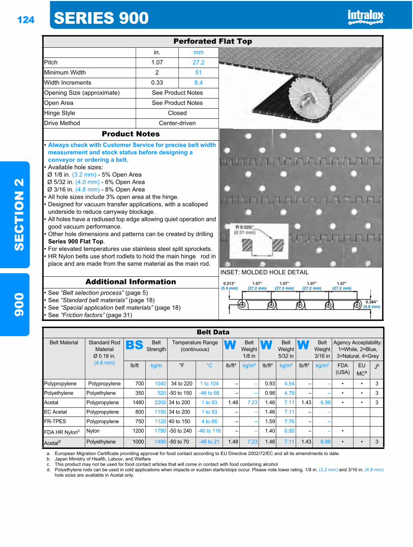
124 SERIES 900S
EC
TIO
N 2
900
Perforated Flat Topin. mm
Pitch 1.07 27.2
Minimum Width 2 51
Width Increments 0.33 8.4
Opening Size (approximate) See Product Notes
Open Area See Product Notes
Hinge Style Closed
Drive Method Center-driven
Product Notes
INSET: MOLDED HOLE DETAIL
• Always check with Customer Service for precise belt width measurement and stock status before designing a conveyor or ordering a belt.
• Available hole sizes: Ø 1/8 in. (3.2 mm) - 5% Open Area Ø 5/32 in. (4.0 mm) - 6% Open Area Ø 3/16 in. (4.8 mm) - 8% Open Area• All hole sizes include 3% open area at the hinge.• Designed for vacuum transfer applications, with a scalloped
underside to reduce carryway blockage.• All holes have a radiused top edge allowing quiet operation and
good vacuum performance.• Other hole dimensions and patterns can be created by drilling
Series 900 Flat Top.• For elevated temperatures use stainless steel split sprockets.• HR Nylon belts use short rodlets to hold the main hinge rod in
place and are made from the same material as the main rod.
Additional Information• See “Belt selection process” (page 5)• See “Standard belt materials” (page 18)• See “Special application belt materials” (page 18)• See “Friction factors” (page 31)
Belt DataBelt Material Standard Rod
MaterialØ 0.18 in. (4.6 mm)
BS Belt Strength
Temperature Range (continuous) W Belt
Weight 1/8 in
W Belt Weight 5/32 in
W Belt Weight 3/16 in
Agency Acceptability:1=White, 2=Blue, 3=Natural, 4=Grey
lb/ft kg/m °F °C lb/ft² kg/m² lb/ft² kg/m² lb/ft² kg/m² FDA (USA)
EUMCa
Jb
Polypropylene Polypropylene 700 1040 34 to 220 1 to 104 – – 0.93 4.54 – – • • 3
Polyethylene Polyethylene 350 520 -50 to 150 -46 to 66 – – 0.98 4.79 – – • • 3
Acetal Polypropylene 1480 2200 34 to 200 1 to 93 1.48 7.23 1.46 7.11 1.43 6.98 • • 3
EC Acetal Polypropylene 800 1190 34 to 200 1 to 93 – – 1.46 7.11 – –
FR-TPES Polypropylene 750 1120 40 to 150 4 to 66 – – 1.59 7.76 – –
FDA HR Nylonc Nylon 1200 1790 -50 to 240 -46 to 116 – – 1.40 6.80 – – •
Acetald Polyethylene 1000 1490 -50 to 70 -46 to 21 1.48 7.23 1.46 7.11 1.43 6.98 • • 3
a. European Migration Certificate providing approval for food contact according to EU Directive 2002/72/EC and all its amendments to date.b. Japan Ministry of Health, Labour, and Welfarec. This product may not be used for food contact articles that will come in contact with food containing alcohold. Polyethylene rods can be used in cold applications when impacts or sudden starts/stops occur. Please note lower rating. 1/8 in. (3.2 mm) and 3/16 in. (4.8 mm)
hole sizes are available in Acetal only.
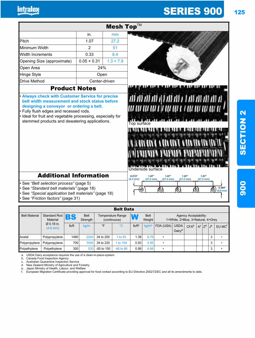
SERIES 900 125
SE
CT
ION
290
0
Mesh TopTM
in. mmPitch 1.07 27.2Minimum Width 2 51Width Increments 0.33 8.4Opening Size (approximate) 0.05 × 0.31 1.3 × 7.9Open Area 24%Hinge Style OpenDrive Method Center-driven
Product Notes
Top surface
Underside surface
• Always check with Customer Service for precise belt width measurement and stock status before designing a conveyor or ordering a belt.
• Fully flush edges and recessed rods.• Ideal for fruit and vegetable processing, especially for
stemmed products and dewatering applications.
Additional Information• See “Belt selection process” (page 5)• See “Standard belt materials” (page 18)• See “Special application belt materials” (page 18)• See “Friction factors” (page 31)
Belt DataBelt Material Standard Rod
MaterialØ 0.18 in. (4.6 mm)
BS Belt Strength
Temperature Range (continuous) W Belt
WeightAgency Acceptability:
1=White, 2=Blue, 3=Natural, 4=Grey
lb/ft kg/m °F °C lb/ft² kg/m² FDA (USA) USDADairya
CFAb Ac Zd Je EU MCf
Acetal Polypropylene 1480 2200 34 to 200 1 to 93 1.39 6.79 • 3 •
Polypropylene Polypropylene 700 1040 34 to 220 1 to 104 0.93 4.55 • 3 •
Polyethylene Polyethylene 350 520 -50 to 150 -46 to 66 0.99 4.84 • 3 •
a. USDA Dairy acceptance requires the use of a clean-in-place-system.b. Canada Food Inspection Agencyc. Australian Quarantine Inspection Serviced. New Zealand Ministry of Agriculture and Forestrye. Japan Ministry of Health, Labour, and Welfaref. European Migration Certificate providing approval for food contact according to EU Directive 2002/72/EC and all its amendments to date.
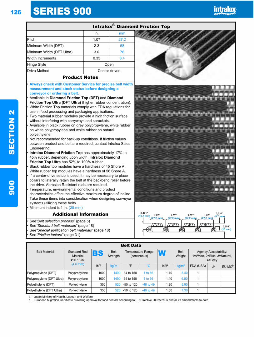
126 SERIES 900S
EC
TIO
N 2
900
Intralox® Diamond Friction Topin. mm
Pitch 1.07 27.2
Minimum Width (DFT) 2.3 58
Minimum Width (DFT Ultra) 3.0 76
Width Increments 0.33 8.4
Hinge Style Open
Drive Method Center-driven
Product Notes• Always check with Customer Service for precise belt width
measurement and stock status before designing a conveyor or ordering a belt.
• Available in Diamond Friction Top (DFT) and Diamond Friction Top Ultra (DFT Ultra) (higher rubber concentration).
• White Friction Top materials comply with FDA regulations for use in food processing and packaging applications.
• Two material rubber modules provide a high friction surface without interfering with carryways and sprockets.
• Available in black rubber on grey polypropylene, white rubber on white polypropylene and white rubber on natural polyethylene.
• Not recommended for back-up conditions. If friction values between product and belt are required, contact Intralox Sales Engineering.
• Intralox Diamond Friction Top has approximately 17% to 45% rubber, depending upon width. Intralox Diamond Friction Top Ultra has 52% to 100% rubber.
• Black rubber top modules have a hardness of 45 Shore A. White rubber top modules have a hardness of 56 Shore A.
• If a center-drive setup is used, it may be necessary to place collars to laterally retain the belt at the backbend roller before the drive. Abrasion Resistant rods are required.
• Temperature, environmental conditions and product characteristics affect the effective maximum degree of incline. Take these items into consideration when designing conveyor systems utilizing these belts.
• Minimum indent is 1 in. (25 mm)
Additional Information• See“Belt selection process” (page 5)• See“Standard belt materials” (page 18)• See“Special application belt materials” (page 18)• See“Friction factors” (page 31)
Belt DataBelt Material Standard Rod
MaterialØ 0.18 in.(4.6 mm)
BS Belt Strength
Temperature Range (continuous) W Belt
WeightAgency Acceptability:
1=White, 2=Blue, 3=Natural, 4=Grey
lb/ft kg/m °F °C lb/ft² kg/m² FDA (USA) Ja EU MCb
Polypropylene (DFT) Polypropylene 1000 1490 34 to 150 1 to 66 1.10 5.40 1
Polypropylene (DFT Ultra) Polypropylene 1000 1490 34 to 150 1 to 66 1.40 6.80 1
Polyethylene (DFT) Polyethylene 350 520 -50 to 120 -46 to 49 1.20 5.90 1
Polyethylene (DFT Ultra) Polyethylene 350 520 -50 to 120 -46 to 49 1.50 7.30 1
a. Japan Ministry of Health, Labour, and Welfareb. European Migration Certificate providing approval for food contact according to EU Directive 2002/72/EC and all its amendments to date.
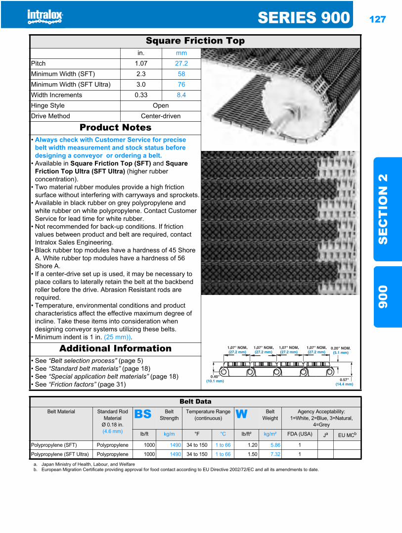
SERIES 900 127
SE
CT
ION
290
0
Square Friction Topin. mm
Pitch 1.07 27.2Minimum Width (SFT) 2.3 58Minimum Width (SFT Ultra) 3.0 76Width Increments 0.33 8.4Hinge Style OpenDrive Method Center-driven
Product Notes• Always check with Customer Service for precise
belt width measurement and stock status before designing a conveyor or ordering a belt.
• Available in Square Friction Top (SFT) and SquareFriction Top Ultra (SFT Ultra) (higher rubber concentration).
• Two material rubber modules provide a high friction surface without interfering with carryways and sprockets.
• Available in black rubber on grey polypropylene and white rubber on white polypropylene. Contact Customer Service for lead time for white rubber.
• Not recommended for back-up conditions. If friction values between product and belt are required, contact Intralox Sales Engineering.
• Black rubber top modules have a hardness of 45 Shore A. White rubber top modules have a hardness of 56 Shore A.
• If a center-drive set up is used, it may be necessary to place collars to laterally retain the belt at the backbend roller before the drive. Abrasion Resistant rods are required.
• Temperature, environmental conditions and product characteristics affect the effective maximum degree of incline. Take these items into consideration when designing conveyor systems utilizing these belts.
• Minimum indent is 1 in. (25 mm)).
Additional Information• See “Belt selection process” (page 5)• See “Standard belt materials” (page 18)• See “Special application belt materials” (page 18)• See “Friction factors” (page 31)
Belt DataBelt Material Standard Rod
MaterialØ 0.18 in. (4.6 mm)
BS Belt Strength
Temperature Range (continuous) W Belt
WeightAgency Acceptability:
1=White, 2=Blue, 3=Natural, 4=Grey
lb/ft kg/m °F °C lb/ft² kg/m² FDA (USA) Ja EU MCb
Polypropylene (SFT) Polypropylene 1000 1490 34 to 150 1 to 66 1.20 5.86 1
Polypropylene (SFT Ultra) Polypropylene 1000 1490 34 to 150 1 to 66 1.50 7.32 1
a. Japan Ministry of Health, Labour, and Welfareb. European Migration Certificate providing approval for food contact according to EU Directive 2002/72/EC and all its amendments to date.
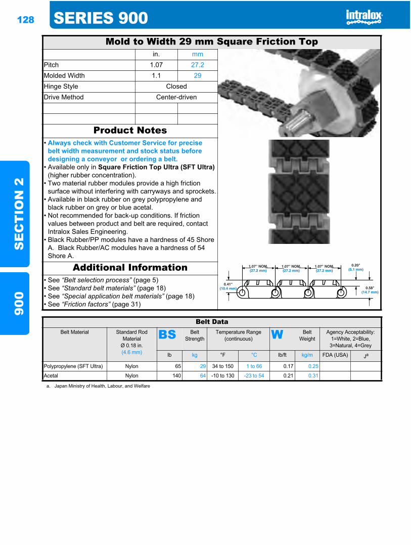
128 SERIES 900S
EC
TIO
N 2
900
Mold to Width 29 mm Square Friction Topin. mm
Pitch 1.07 27.2Molded Width 1.1 29Hinge Style ClosedDrive Method Center-driven
Product Notes• Always check with Customer Service for precise
belt width measurement and stock status before designing a conveyor or ordering a belt.
• Available only in Square Friction Top Ultra (SFT Ultra)(higher rubber concentration).
• Two material rubber modules provide a high friction surface without interfering with carryways and sprockets.
• Available in black rubber on grey polypropylene and black rubber on grey or blue acetal.
• Not recommended for back-up conditions. If friction values between product and belt are required, contact Intralox Sales Engineering.
• Black Rubber/PP modules have a hardness of 45 Shore A. Black Rubber/AC modules have a hardness of 54 Shore A.
Additional Information• See “Belt selection process” (page 5)• See “Standard belt materials” (page 18)• See “Special application belt materials” (page 18)• See “Friction factors” (page 31)
Belt DataBelt Material Standard Rod
MaterialØ 0.18 in. (4.6 mm)
BS Belt Strength
Temperature Range (continuous) W Belt
WeightAgency Acceptability:
1=White, 2=Blue, 3=Natural, 4=Grey
lb kg °F °C lb/ft kg/m FDA (USA) Ja
Polypropylene (SFT Ultra) Nylon 65 29 34 to 150 1 to 66 0.17 0.25
Acetal Nylon 140 64 -10 to 130 -23 to 54 0.21 0.31
a. Japan Ministry of Health, Labour, and Welfare
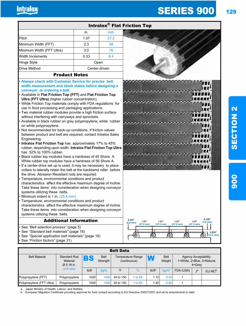
SERIES 900 129
SE
CT
ION
290
0
Intralox® Flat Friction Topin. mm
Pitch 1.07 27.2
Minimum Width (FFT) 2.3 58
Minimum Width (FFT Ultra) 3.0 76
Width Increments 0.33 8.4
Hinge Style Open
Drive Method Center-driven
Product Notes• Always check with Customer Service for precise belt
width measurement and stock status before designing a conveyor or ordering a belt.
• Available in Flat Friction Top (FFT) and Flat Friction Top Ultra (FFT Ultra) (higher rubber concentration).
• White Friction Top materials comply with FDA regulations for use in food processing and packaging applications.
• Two material rubber modules provide a high friction surface without interfering with carryways and sprockets.
• Available in black rubber on grey polypropylene, white rubber on white polypropylene.
• Not recommended for back-up conditions. If friction values between product and belt are required, contact Intralox Sales Engineering.
• Intralox Flat Friction Top has approximately 17% to 45% rubber, depending upon width. Intralox Flat Friction Top Ultrahas 52% to 100% rubber.
• Black rubber top modules have a hardness of 45 Shore A. White rubber top modules have a hardness of 56 Shore A.
• If a center-drive set up is used, it may be necessary to place collars to laterally retain the belt at the backbend roller before the drive. Abrasion Resistant rods are required.
• Temperature, environmental conditions and product characteristics affect the effective maximum degree of incline. Take these items into consideration when designing conveyor systems utilizing these belts.
• Minimum indent is 1 in. (25.4 mm)• Temperature, environmental conditions and product
characteristics affect the effective maximum degree of incline. Take these items into consideration when designing conveyor systems utilizing these belts.
Additional Information• See “Belt selection process” (page 5)• See “Standard belt materials” (page 18)• See “Special application belt materials” (page 18)• See “Friction factors” (page 31)
Belt DataBelt Material Standard Rod
MaterialØ 0.18 in. (4.6 mm)
BS Belt Strength
Temperature Range (continuous) W Belt
WeightAgency Acceptability:
1=White, 2=Blue, 3=Natural, 4=Grey
lb/ft kg/m °F °C lb/ft² kg/m² FDA (USA) Ja EU MCb
Polypropylene (FFT) Polypropylene 1000 1490 34 to 150 1 to 66 1.10 5.40 1
Polypropylene (FFT Ultra) Polypropylene 1000 1490 34 to 150 1 to 66 1.40 6.80 1
a. Japan Ministry of Health, Labour, and Welfareb. European Migration Certificate providing approval for food contact according to EU Directive 2002/72/EC and all its amendments to date.
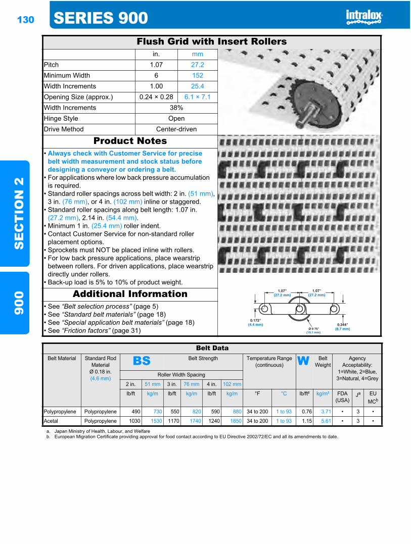
130 SERIES 900S
EC
TIO
N 2
900
Flush Grid with Insert Rollersin. mm
Pitch 1.07 27.2Minimum Width 6 152Width Increments 1.00 25.4Opening Size (approx.) 0.24 × 0.28 6.1 × 7.1Width Increments 38%Hinge Style OpenDrive Method Center-driven
Product Notes• Always check with Customer Service for precise
belt width measurement and stock status before designing a conveyor or ordering a belt.
• For applications where low back pressure accumulation is required.
• Standard roller spacings across belt width: 2 in. (51 mm),3 in. (76 mm), or 4 in. (102 mm) inline or staggered.
• Standard roller spacings along belt length: 1.07 in. (27.2 mm), 2.14 in. (54.4 mm).
• Minimum 1 in. (25.4 mm) roller indent.• Contact Customer Service for non-standard roller
placement options.• Sprockets must NOT be placed inline with rollers.• For low back pressure applications, place wearstrip
between rollers. For driven applications, place wearstrip directly under rollers.
• Back-up load is 5% to 10% of product weight.
Additional Information• See “Belt selection process” (page 5)• See “Standard belt materials” (page 18)• See “Special application belt materials” (page 18)• See “Friction factors” (page 31)
Belt DataBelt Material Standard Rod
MaterialØ 0.18 in. (4.6 mm)
BS Belt Strength Temperature Range (continuous) W Belt
WeightAgency
Acceptability:1=White, 2=Blue, 3=Natural, 4=Grey
Roller Width Spacing
2 in. 51 mm 3 in. 76 mm 4 in. 102 mm
lb/ft kg/m lb/ft kg/m lb/ft kg/m °F °C lb/ft² kg/m² FDA(USA)
Ja EU MCb
Polypropylene Polypropylene 490 730 550 820 590 880 34 to 200 1 to 93 0.76 3.71 • 3 •
Acetal Polypropylene 1030 1530 1170 1740 1240 1850 34 to 200 1 to 93 1.15 5.61 • 3 •
a. Japan Ministry of Health, Labour, and Welfareb. European Migration Certificate providing approval for food contact according to EU Directive 2002/72/EC and all its amendments to date.
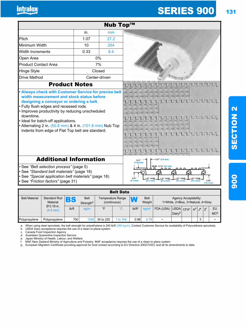
SERIES 900 131
SE
CT
ION
290
0
Nub Top™in. mm
Pitch 1.07 27.2Minimum Width 10 254Width Increments 0.33 8.4Open Area 0%Product Contact Area 7%Hinge Style ClosedDrive Method Center-driven
Product Notes• Always check with Customer Service for precise belt
width measurement and stock status before designing a conveyor or ordering a belt.
• Fully flush edges and recessed rods.• Improves productivity by reducing unscheduled
downtime.• Ideal for batch-off applications.• Alternating 2 in. (50.8 mm) & 4 in. (101.6 mm) Nub Top
indents from edge of Flat Top belt are standard.
Additional Information• See “Belt selection process” (page 5)• See “Standard belt materials” (page 18)• See “Special application belt materials” (page 18)• See “Friction factors” (page 31)
Belt DataBelt Material Standard Rod
MaterialØ 0.18 in. (4.6 mm)
BS Belt Strengtha
Temperature Range (continuous) W Belt
WeightAgency Acceptability:
1=White, 2=Blue, 3=Natural, 4=Grey
lb/ft kg/m °F °C lb/ft² kg/m² FDA (USA) USDADairyb
CFAc Ad Je Zf EU MCg
Polypropylene Polypropylene 700 1040 34 to 220 1 to 104 0.98 4.78 • 3 •
a. When using steel sprockets, the belt strength for polyethylene is 240 lb/ft (360 kg/m). Contact Customer Service for availability of Polyurethane sprockets.b. USDA Dairy acceptance requires the use of a clean-in-place-system.c. Canada Food Inspection Agencyd. Australian Quarantine Inspection Servicee. Japan Ministry of Health, Labour, and Welfaref. MAF-New Zealand Ministry of Agriculture and Forestry. MAF acceptance requires the use of a clean-in-place system.g. European Migration Certificate providing approval for food contact according to EU Directive 2002/72/EC and all its amendments to date.
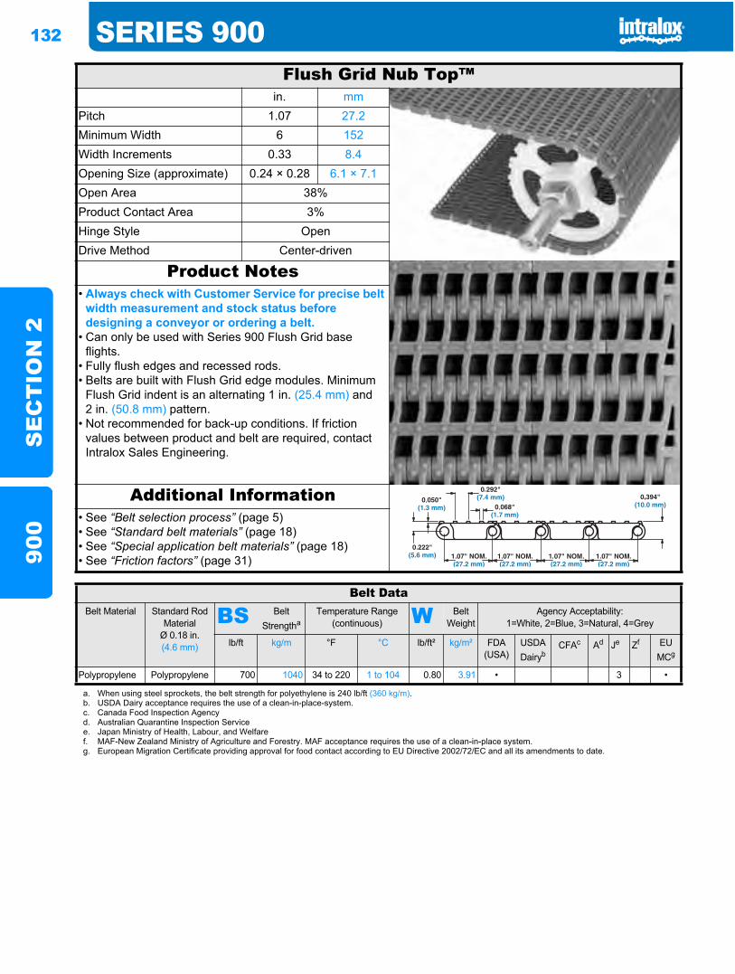
132 SERIES 900S
EC
TIO
N 2
900
Flush Grid Nub Top™in. mm
Pitch 1.07 27.2Minimum Width 6 152Width Increments 0.33 8.4Opening Size (approximate) 0.24 × 0.28 6.1 × 7.1Open Area 38%Product Contact Area 3%Hinge Style OpenDrive Method Center-driven
Product Notes• Always check with Customer Service for precise belt
width measurement and stock status before designing a conveyor or ordering a belt.
• Can only be used with Series 900 Flush Grid base flights.
• Fully flush edges and recessed rods.• Belts are built with Flush Grid edge modules. Minimum
Flush Grid indent is an alternating 1 in. (25.4 mm) and 2 in. (50.8 mm) pattern.
• Not recommended for back-up conditions. If friction values between product and belt are required, contact Intralox Sales Engineering.
Additional Information• See “Belt selection process” (page 5)• See “Standard belt materials” (page 18)• See “Special application belt materials” (page 18)• See “Friction factors” (page 31)
Belt DataBelt Material Standard Rod
MaterialØ 0.18 in. (4.6 mm)
BS Belt Strengtha
Temperature Range (continuous) W Belt
WeightAgency Acceptability:
1=White, 2=Blue, 3=Natural, 4=Grey
lb/ft kg/m °F °C lb/ft² kg/m² FDA (USA)
USDADairyb
CFAc Ad Je Zf EU MCg
Polypropylene Polypropylene 700 1040 34 to 220 1 to 104 0.80 3.91 • 3 •
a. When using steel sprockets, the belt strength for polyethylene is 240 lb/ft (360 kg/m).b. USDA Dairy acceptance requires the use of a clean-in-place-system.c. Canada Food Inspection Agencyd. Australian Quarantine Inspection Servicee. Japan Ministry of Health, Labour, and Welfaref. MAF-New Zealand Ministry of Agriculture and Forestry. MAF acceptance requires the use of a clean-in-place system.g. European Migration Certificate providing approval for food contact according to EU Directive 2002/72/EC and all its amendments to date.
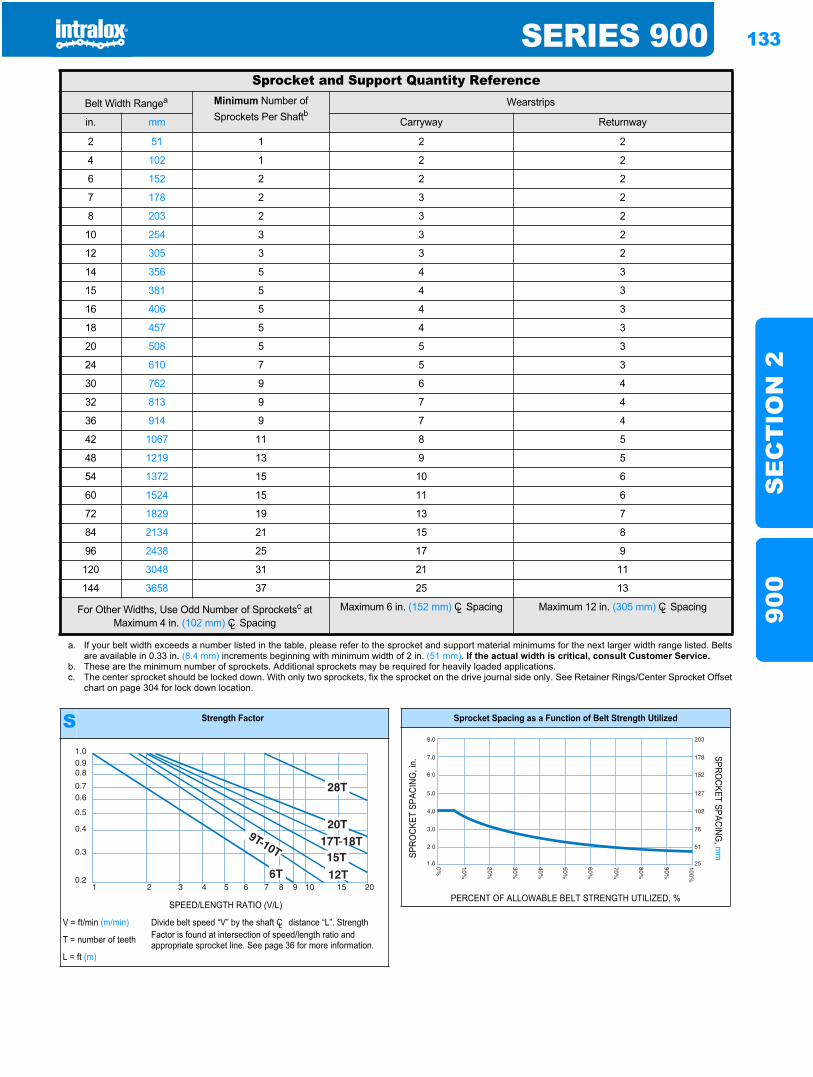
SERIES 900 133
SE
CT
ION
290
0
Sprocket and Support Quantity ReferenceBelt Width Rangea Minimum Number of
Sprockets Per ShaftbWearstrips
in. mm Carryway Returnway
2 51 1 2 2
4 102 1 2 2
6 152 2 2 2
7 178 2 3 2
8 203 2 3 2
10 254 3 3 2
12 305 3 3 2
14 356 5 4 3
15 381 5 4 3
16 406 5 4 3
18 457 5 4 3
20 508 5 5 3
24 610 7 5 3
30 762 9 6 4
32 813 9 7 4
36 914 9 7 4
42 1067 11 8 5
48 1219 13 9 5
54 1372 15 10 6
60 1524 15 11 6
72 1829 19 13 7
84 2134 21 15 8
96 2438 25 17 9
120 3048 31 21 11
144 3658 37 25 13
For Other Widths, Use Odd Number of Sprocketsc at Maximum 4 in. (102 mm) CL Spacing
Maximum 6 in. (152 mm) CL Spacing Maximum 12 in. (305 mm) CL Spacing
a. If your belt width exceeds a number listed in the table, please refer to the sprocket and support material minimums for the next larger width range listed. Beltsare available in 0.33 in. (8.4 mm) increments beginning with minimum width of 2 in. (51 mm). If the actual width is critical, consult Customer Service.
b. These are the minimum number of sprockets. Additional sprockets may be required for heavily loaded applications.c. The center sprocket should be locked down. With only two sprockets, fix the sprocket on the drive journal side only. See Retainer Rings/Center Sprocket Offset
chart on page 304 for lock down location.
S Strength Factor
SPEED/LENGTH RATIO (V/L)
V = ft/min (m/min) Divide belt speed “V” by the shaft CL distance “L”. Strength Factor is found at intersection of speed/length ratio and appropriate sprocket line. See page 36 for more information.T = number of teeth
L = ft (m)
1.00.90.8
0.70.6
0.5
0.4
0.3
0.21 2 3 4 5 6 7 8 9 10 15 20
Sprocket Spacing as a Function of Belt Strength Utilized
SPRO
CKET
SPA
CING
, in.
SPROCKET SPACING
, mm
PERCENT OF ALLOWABLE BELT STRENGTH UTILIZED, %
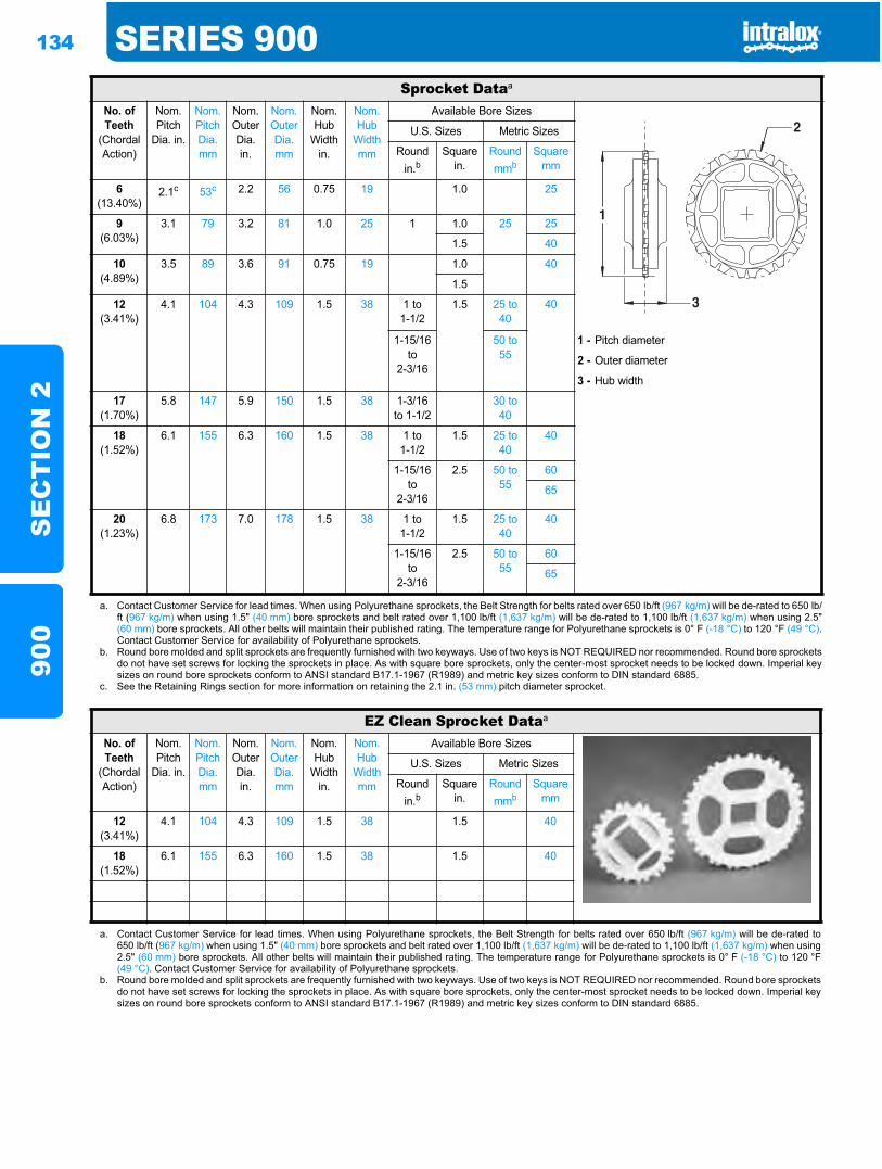
134 SERIES 900S
EC
TIO
N 2
900
Sprocket Dataa
No. of Teeth
(Chordal Action)
Nom. Pitch
Dia. in.
Nom. Pitch Dia.mm
Nom. Outer Dia. in.
Nom. Outer Dia. mm
Nom. Hub
Width in.
Nom. Hub
Width mm
Available Bore Sizes
U.S. Sizes Metric Sizes
Round in.b
Square in.
Round mmb
Square mm
6(13.40%)
2.1c 53c 2.2 56 0.75 19 1.0 25
9(6.03%)
3.1 79 3.2 81 1.0 25 1 1.0 25 25
1.5 40
10(4.89%)
3.5 89 3.6 91 0.75 19 1.0 40
1.5
12(3.41%)
4.1 104 4.3 109 1.5 38 1 to1-1/2
1.5 25 to 40
40
1-15/16to
2-3/16
50 to 55
1 - Pitch diameter
2 - Outer diameter
3 - Hub width
17(1.70%)
5.8 147 5.9 150 1.5 38 1-3/16 to 1-1/2
30 to 40
18(1.52%)
6.1 155 6.3 160 1.5 38 1 to1-1/2
1.5 25 to 40
40
1-15/16to
2-3/16
2.5 50 to 55
60
65
20(1.23%)
6.8 173 7.0 178 1.5 38 1 to1-1/2
1.5 25 to 40
40
1-15/16to
2-3/16
2.5 50 to 55
60
65
a. Contact Customer Service for lead times. When using Polyurethane sprockets, the Belt Strength for belts rated over 650 lb/ft (967 kg/m) will be de-rated to 650 lb/ft (967 kg/m) when using 1.5" (40 mm) bore sprockets and belt rated over 1,100 lb/ft (1,637 kg/m) will be de-rated to 1,100 lb/ft (1,637 kg/m) when using 2.5"(60 mm) bore sprockets. All other belts will maintain their published rating. The temperature range for Polyurethane sprockets is 0° F (-18 °C) to 120 °F (49 °C).Contact Customer Service for availability of Polyurethane sprockets.
b. Round bore molded and split sprockets are frequently furnished with two keyways. Use of two keys is NOT REQUIRED nor recommended. Round bore sprocketsdo not have set screws for locking the sprockets in place. As with square bore sprockets, only the center-most sprocket needs to be locked down. Imperial keysizes on round bore sprockets conform to ANSI standard B17.1-1967 (R1989) and metric key sizes conform to DIN standard 6885.
c. See the Retaining Rings section for more information on retaining the 2.1 in. (53 mm) pitch diameter sprocket.
EZ Clean Sprocket Dataa
No. of Teeth
(Chordal Action)
Nom. Pitch
Dia. in.
Nom. Pitch Dia.mm
Nom. Outer Dia. in.
Nom. Outer Dia. mm
Nom. Hub
Width in.
Nom. Hub
Width mm
Available Bore Sizes
U.S. Sizes Metric Sizes
Round in.b
Square in.
Round mmb
Square mm
12(3.41%)
4.1 104 4.3 109 1.5 38 1.5 40
18(1.52%)
6.1 155 6.3 160 1.5 38 1.5 40
a. Contact Customer Service for lead times. When using Polyurethane sprockets, the Belt Strength for belts rated over 650 lb/ft (967 kg/m) will be de-rated to650 lb/ft (967 kg/m) when using 1.5" (40 mm) bore sprockets and belt rated over 1,100 lb/ft (1,637 kg/m) will be de-rated to 1,100 lb/ft (1,637 kg/m) when using2.5" (60 mm) bore sprockets. All other belts will maintain their published rating. The temperature range for Polyurethane sprockets is 0° F (-18 °C) to 120 °F(49 °C). Contact Customer Service for availability of Polyurethane sprockets.
b. Round bore molded and split sprockets are frequently furnished with two keyways. Use of two keys is NOT REQUIRED nor recommended. Round bore sprocketsdo not have set screws for locking the sprockets in place. As with square bore sprockets, only the center-most sprocket needs to be locked down. Imperial keysizes on round bore sprockets conform to ANSI standard B17.1-1967 (R1989) and metric key sizes conform to DIN standard 6885.
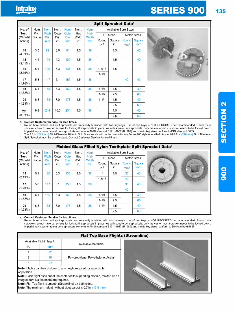
SERIES 900 135
SE
CT
ION
290
0
Split Sprocket Dataa
No. of Teeth
(Chordal Action)
Nom. Pitch
Dia. in.
Nom. Pitch Dia. mm
Nom. Outer Dia.in.
Nom. Outer Dia.mm
Nom. Hub
Width in.
Nom. Hub
Width mm
Available Bore Sizes
U.S. Sizes Metric Sizes
Round in.b
Square in.
Round mmb
Square mm
10(4.89%)
3.5 89 3.6 91 1.5 38 1.5 40
12(3.41%)
4.1 104 4.3 109 1.5 38 1.5 40
15(2.19%)
5.1 130 5.3 135 1.5 38 1-3/16 1.5
1-1/4
17(1.70%)
5.8 147 6.1 155 1.5 38 40 40
18(1.52%)
6.1 155 6.3 160 1.5 38 1-1/4 1.5 40
1-1/2 2.5 60
20(1.23%)
6.8 173 7.0 178 1.5 38 1-1/4 1.5 40
2.5 60
28c
(0.63%)9.8 249 10.0 254 1.5 38 1.5 40
2.5 60
a. Contact Customer Service for lead times.b. Round bore molded and split sprockets are frequently furnished with two keyways. Use of two keys is NOT REQUIRED nor recommended. Round bore
sprockets do not have set screws for locking the sprockets in place. As with square bore sprockets, only the center-most sprocket needs to be locked down.Imperial key sizes on round bore sprockets conform to ANSI standard B17.1-1967 (R1989) and metric key sizes conform to DIN standard 6885.
c. The 9.8 in. (249 mm) Pitch Diameter 28 tooth Split Sprocket should not be used with any Series 900 style Acetal belt. A special 9.7 in. (246 mm) Pitch DiameterSplit Sprocket must be used instead. Contact Customer Service for lead times.
Molded Glass Filled Nylon Toothplate Split Sprocket Dataa
No. of Teeth
(Chordal Action)
Nom. Pitch
Dia. in.
Nom. Pitch Dia. mm
Nom. Outer Dia.in.
Nom. Outer Dia.mm
Nom. Hub
Width in.
Nom. Hub
Width mm
Available Bore Sizes
U.S. Sizes Metric Sizes
Round in.b
Square in.
Round mmb
Square mm
15(2.19%)
5.1 130 5.3 135 1.5 38 1 1.5 30 40
1-3/16 40
17(1.70%)
5.8 147 6.1 155 1.5 38 30 40
40
18(1.52%)
6.1 155 6.3 160 1.5 38 1-1/4 1.5 40
1-1/2 2.5 60
20(1.23%)
6.8 173 7.0 178 1.5 38 1-1/4 1.5 40
2.5 60
a. Contact Customer Service for lead times.b. Round bore molded and split sprockets are frequently furnished with two keyways. Use of two keys is NOT REQUIRED nor recommended. Round bore
sprockets do not have set screws for locking the sprockets in place. As with square bore sprockets, only the center-most sprocket needs to be locked down.Imperial key sizes on round bore sprockets conform to ANSI standard B17.1-1967 (R1989) and metric key sizes conform to DIN standard 6885.
Flat Top Base Flights (Streamline)Available Flight Height
Available Materialsin. mm
1 25
Polypropylene, Polyethylene, Acetal2 51
3 76
Note: Flights can be cut down to any height required for a particular application.Note: Each flight rises out of the center of its supporting module, molded as an integral part. No fasteners are required.Note: Flat Top flight is smooth (Streamline) on both sides.Note: The minimum indent (without sideguards) is 0.7 in. (17.8 mm).
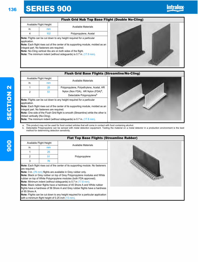
136 SERIES 900S
EC
TIO
N 2
900
Flush Grid Nub Top Base Flight (Double No-Cling)Available Flight Height
Available Materialsin. mm
4 102 Polypropylene, Acetal
Note: Flights can be cut down to any height required for a particular application.Note: Each flight rises out of the center of its supporting module, molded as an integral part. No fasteners are required.Note: No-Cling vertical ribs are on both sides of the flight.Note: The minimum indent (without sideguards) is 0.7 in. (17.8 mm).
Flush Grid Base Flights (Streamline/No-Cling)Available Flight Height
Available Materialsin. mm
1 25 Polypropylene, Polyethylene, Acetal, HR Nylon (Non FDA), HR Nylon (FDA)a,
Detectable Polypropyleneb2 51
Note: Flights can be cut down to any height required for a particular application.Note: Each flight rises out of the center of its supporting module, molded as an integral part. No fasteners are required.Note: One side of the Flush Grid flight is smooth (Streamline) while the other is ribbed vertically (No-Cling).Note: The minimum indent (without sideguards) is 0.7 in. (17.8 mm).
a. This product may not be used for food contact articles that will come in contact with food containing alcohol.b. Detectable Polypropylene can be sensed with metal detection equipment. Testing the material on a metal detector in a production environment is the best
method for determining detection sensitivity.
Flat Top Base Flights (Streamline Rubber)Available Flight Height
Available Materialsin. mm
1 25
Polypropylene2 51
3 76
Note: Each flight rises out of the center of its supporting module. No fasteners are required.Note: 3 in. (76 mm) flights are available in Grey rubber only.Note: Black or Grey rubber on top of Grey Polypropylene modules and White rubber on top of White Polypropylene modules (both FDA approved).Note: Minimum indent (without sideguards) is 0.7 in (17.8 mm).Note: Black rubber flights have a hardness of 45 Shore A and White rubber flights have a hardness of 56 Shore A and Grey rubber flights have a hardness of 85 Shore A.Note: Flights can be cut down to any height required for a particular application with a minimum flight height of 0.25 inch (13 mm).
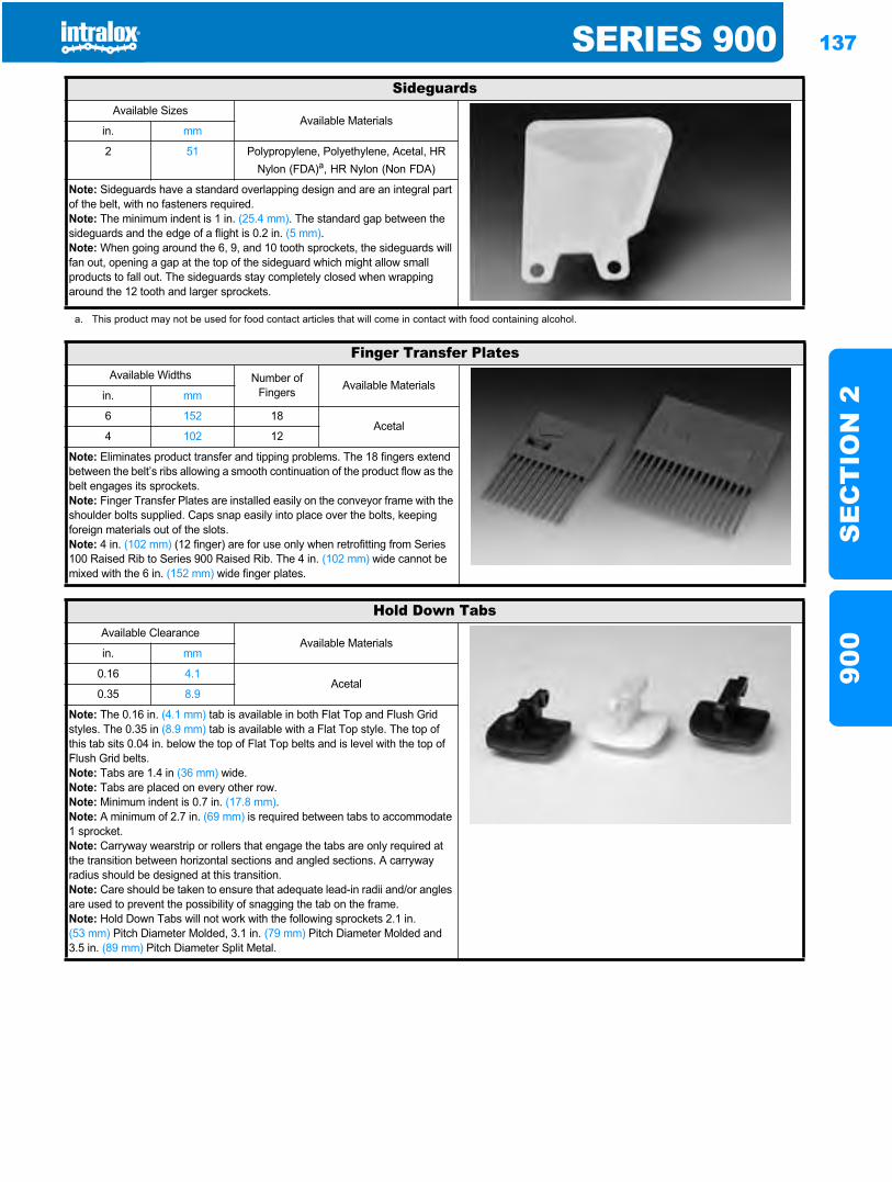
SERIES 900 137
SE
CT
ION
290
0
SideguardsAvailable Sizes
Available Materialsin. mm
2 51 Polypropylene, Polyethylene, Acetal, HR Nylon (FDA)a, HR Nylon (Non FDA)
Note: Sideguards have a standard overlapping design and are an integral part of the belt, with no fasteners required.Note: The minimum indent is 1 in. (25.4 mm). The standard gap between the sideguards and the edge of a flight is 0.2 in. (5 mm).Note: When going around the 6, 9, and 10 tooth sprockets, the sideguards will fan out, opening a gap at the top of the sideguard which might allow small products to fall out. The sideguards stay completely closed when wrapping around the 12 tooth and larger sprockets.
a. This product may not be used for food contact articles that will come in contact with food containing alcohol.
Finger Transfer PlatesAvailable Widths Number of
Fingers Available Materialsin. mm
6 152 18Acetal
4 102 12
Note: Eliminates product transfer and tipping problems. The 18 fingers extend between the belt’s ribs allowing a smooth continuation of the product flow as the belt engages its sprockets.Note: Finger Transfer Plates are installed easily on the conveyor frame with the shoulder bolts supplied. Caps snap easily into place over the bolts, keeping foreign materials out of the slots.Note: 4 in. (102 mm) (12 finger) are for use only when retrofitting from Series 100 Raised Rib to Series 900 Raised Rib. The 4 in. (102 mm) wide cannot be mixed with the 6 in. (152 mm) wide finger plates.
Hold Down TabsAvailable Clearance
Available Materialsin. mm
0.16 4.1Acetal
0.35 8.9
Note: The 0.16 in. (4.1 mm) tab is available in both Flat Top and Flush Grid styles. The 0.35 in (8.9 mm) tab is available with a Flat Top style. The top of this tab sits 0.04 in. below the top of Flat Top belts and is level with the top of Flush Grid belts.Note: Tabs are 1.4 in (36 mm) wide.Note: Tabs are placed on every other row.Note: Minimum indent is 0.7 in. (17.8 mm).Note: A minimum of 2.7 in. (69 mm) is required between tabs to accommodate 1 sprocket.Note: Carryway wearstrip or rollers that engage the tabs are only required at the transition between horizontal sections and angled sections. A carryway radius should be designed at this transition.Note: Care should be taken to ensure that adequate lead-in radii and/or angles are used to prevent the possibility of snagging the tab on the frame.Note: Hold Down Tabs will not work with the following sprockets 2.1 in. (53 mm) Pitch Diameter Molded, 3.1 in. (79 mm) Pitch Diameter Molded and 3.5 in. (89 mm) Pitch Diameter Split Metal.
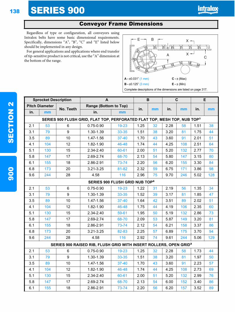
138 SERIES 900S
EC
TIO
N 2
900
Regardless of type or configuration, all conveyors usingIntralox belts have some basic dimensional requirements.Specifically, dimensions “A”, “B”, “C” and “E” listed belowshould be implemented in any design.
For general applications and applications where end transferof tip-sensitive product is not critical, use the “A” dimension atthe bottom of the range.
Conveyor Frame Dimensions
A - ±0.031” (1 mm) C - ± (Max)
B - ±0.125” (3 mm) E - ± (Min)
Complete descriptions of the dimensions are listed on page 317.
Sprocket Description A B C EPitch Diameter
No. TeethRange (Bottom to Top)
in. mm in. mm in. mmin. mm in. mm
SERIES 900 FLUSH GRID, FLAT TOP, PERFORATED FLAT TOP, MESH TOP, NUB TOPa
2.1 53 6 0.75-0.90 19-23 1.25 32 2.28 58 1.51 383.1 79 9 1.30-1.39 33-35 1.51 38 3.20 81 1.75 443.5 89 10 1.47-1.56 37-40 1.70 43 3.60 91 2.01 514.1 104 12 1.82-1.90 46-48 1.74 44 4.25 108 2.51 645.1 130 15 2.34-2.40 60-61 2.00 51 5.20 132 2.77 705.8 147 17 2.69-2.74 68-70 2.13 54 5.80 147 3.15 806.1 155 18 2.86-2.91 73-74 2.20 56 6.20 155 3.30 846.8 173 20 3.21-3.25 81-82 2.32 59 6.75 171 3.86 989.6 244 28 4.58 116 2.96 75 9.70 246 5.02 128
SERIES 900 FLUSH GRID NUB TOPa
2.1 53 6 0.75-0.90 19-23 1.22 31 2.19 56 1.35 343.1 79 9 1.30-1.39 33-35 1.52 39 3.17 81 1.85 473.5 89 10 1.47-1.56 37-40 1.64 42 3.51 89 2.02 514.1 104 12 1.82-1.90 46-48 1.75 44 4.19 106 2.35 605.1 130 15 2.34-2.40 59-61 1.95 50 5.19 132 2.86 735.8 147 17 2.69-2.74 68-70 2.09 53 5.87 149 3.20 816.1 155 18 2.86-2.91 73-74 2.12 54 6.21 158 3.37 866.8 173 20 3.21-3.25 82-83 2.25 57 6.89 175 3.70 949.6 244 28 4.58 116 2.92 74 9.61 244 5.06 129
SERIES 900 RAISED RIB, FLUSH GRID WITH INSERT ROLLERS, OPEN GRIDa
2.1 53 6 0.75-0.90 19-23 1.25 32 2.28 58 1.73 443.1 79 9 1.30-1.39 33-35 1.51 38 3.20 81 1.97 503.5 89 10 1.47-1.56 37-40 1.70 43 3.60 91 2.23 574.1 104 12 1.82-1.90 46-48 1.74 44 4.25 108 2.73 695.1 130 15 2.34-2.40 60-61 2.00 51 5.20 132 2.99 765.8 147 17 2.69-2.74 68-70 2.13 54 6.00 152 3.40 866.1 155 18 2.86-2.91 73-74 2.20 56 6.20 157 3.52 89
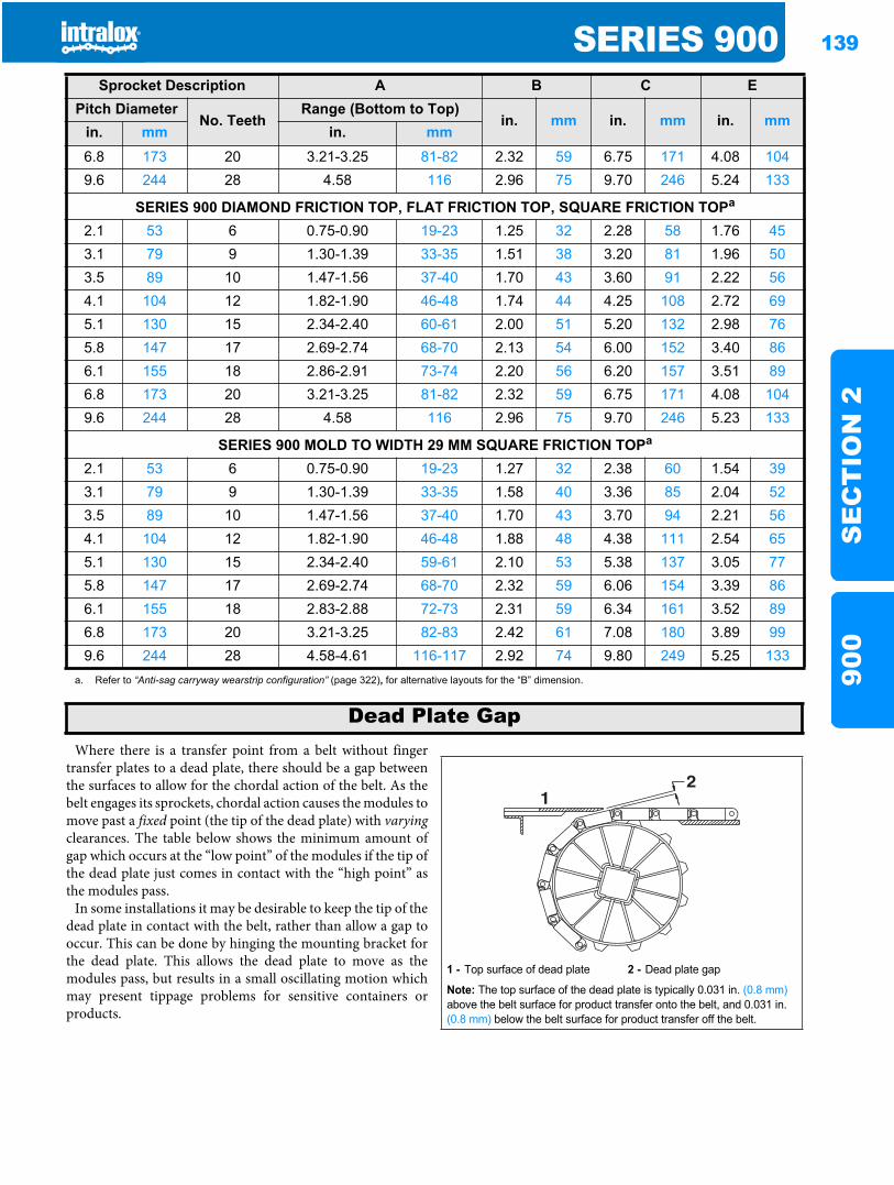
SERIES 900 139
SE
CT
ION
290
0
Where there is a transfer point from a belt without fingertransfer plates to a dead plate, there should be a gap betweenthe surfaces to allow for the chordal action of the belt. As thebelt engages its sprockets, chordal action causes the modules tomove past a fixed point (the tip of the dead plate) with varyingclearances. The table below shows the minimum amount ofgap which occurs at the “low point” of the modules if the tip ofthe dead plate just comes in contact with the “high point” asthe modules pass.
In some installations it may be desirable to keep the tip of thedead plate in contact with the belt, rather than allow a gap tooccur. This can be done by hinging the mounting bracket forthe dead plate. This allows the dead plate to move as themodules pass, but results in a small oscillating motion whichmay present tippage problems for sensitive containers orproducts.
6.8 173 20 3.21-3.25 81-82 2.32 59 6.75 171 4.08 1049.6 244 28 4.58 116 2.96 75 9.70 246 5.24 133
SERIES 900 DIAMOND FRICTION TOP, FLAT FRICTION TOP, SQUARE FRICTION TOPa
2.1 53 6 0.75-0.90 19-23 1.25 32 2.28 58 1.76 453.1 79 9 1.30-1.39 33-35 1.51 38 3.20 81 1.96 503.5 89 10 1.47-1.56 37-40 1.70 43 3.60 91 2.22 564.1 104 12 1.82-1.90 46-48 1.74 44 4.25 108 2.72 695.1 130 15 2.34-2.40 60-61 2.00 51 5.20 132 2.98 765.8 147 17 2.69-2.74 68-70 2.13 54 6.00 152 3.40 866.1 155 18 2.86-2.91 73-74 2.20 56 6.20 157 3.51 896.8 173 20 3.21-3.25 81-82 2.32 59 6.75 171 4.08 1049.6 244 28 4.58 116 2.96 75 9.70 246 5.23 133
SERIES 900 MOLD TO WIDTH 29 MM SQUARE FRICTION TOPa
2.1 53 6 0.75-0.90 19-23 1.27 32 2.38 60 1.54 393.1 79 9 1.30-1.39 33-35 1.58 40 3.36 85 2.04 523.5 89 10 1.47-1.56 37-40 1.70 43 3.70 94 2.21 564.1 104 12 1.82-1.90 46-48 1.88 48 4.38 111 2.54 655.1 130 15 2.34-2.40 59-61 2.10 53 5.38 137 3.05 775.8 147 17 2.69-2.74 68-70 2.32 59 6.06 154 3.39 866.1 155 18 2.83-2.88 72-73 2.31 59 6.34 161 3.52 896.8 173 20 3.21-3.25 82-83 2.42 61 7.08 180 3.89 999.6 244 28 4.58-4.61 116-117 2.92 74 9.80 249 5.25 133
a. Refer to “Anti-sag carryway wearstrip configuration” (page 322), for alternative layouts for the “B” dimension.
Sprocket Description A B C EPitch Diameter
No. TeethRange (Bottom to Top)
in. mm in. mm in. mmin. mm in. mm
Dead Plate Gap
1 - Top surface of dead plate 2 - Dead plate gap
Note: The top surface of the dead plate is typically 0.031 in. (0.8 mm)above the belt surface for product transfer onto the belt, and 0.031 in. (0.8 mm) below the belt surface for product transfer off the belt.
21
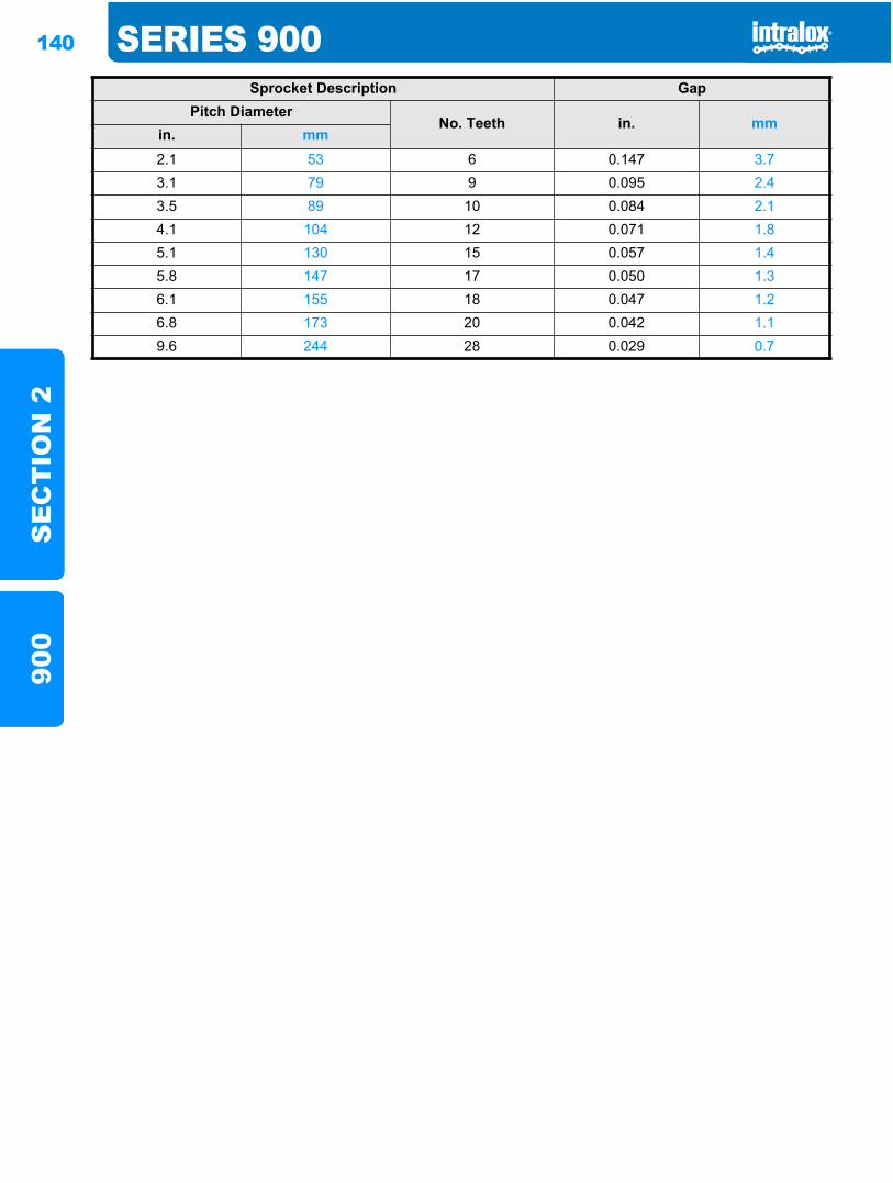
140 SERIES 900S
EC
TIO
N 2
900
Sprocket Description GapPitch Diameter
No. Teeth in. mmin. mm2.1 53 6 0.147 3.73.1 79 9 0.095 2.43.5 89 10 0.084 2.14.1 104 12 0.071 1.85.1 130 15 0.057 1.45.8 147 17 0.050 1.36.1 155 18 0.047 1.26.8 173 20 0.042 1.19.6 244 28 0.029 0.7
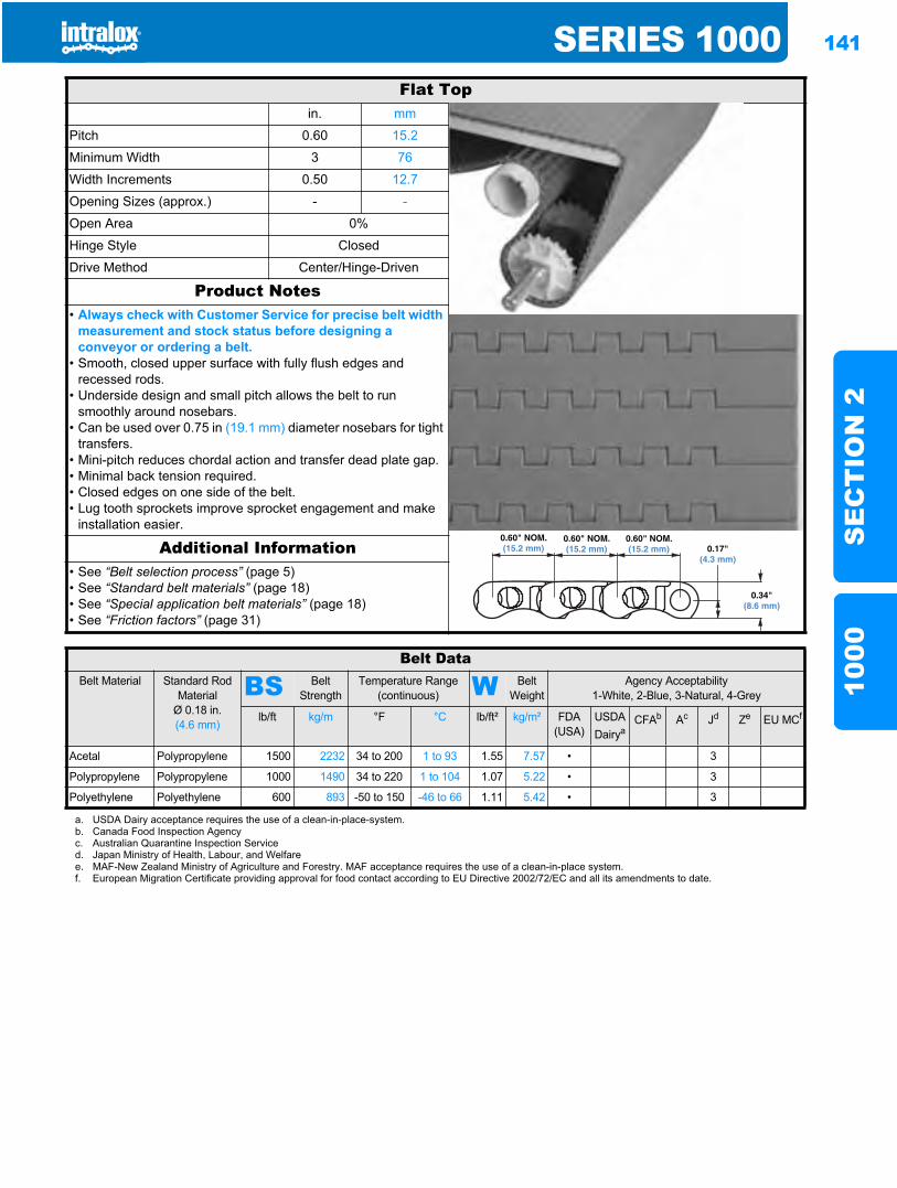
SERIES 1000 141
SE
CT
ION
210
00
Series 10001000
Flat Topin. mm
Pitch 0.60 15.2
Minimum Width 3 76
Width Increments 0.50 12.7
Opening Sizes (approx.) - -
Open Area 0%
Hinge Style Closed
Drive Method Center/Hinge-Driven
Product Notes• Always check with Customer Service for precise belt width
measurement and stock status before designing a conveyor or ordering a belt.
• Smooth, closed upper surface with fully flush edges and recessed rods.
• Underside design and small pitch allows the belt to run smoothly around nosebars.
• Can be used over 0.75 in (19.1 mm) diameter nosebars for tight transfers.
• Mini-pitch reduces chordal action and transfer dead plate gap.• Minimal back tension required.• Closed edges on one side of the belt.• Lug tooth sprockets improve sprocket engagement and make
installation easier.
Additional Information• See “Belt selection process” (page 5)• See “Standard belt materials” (page 18)• See “Special application belt materials” (page 18)• See “Friction factors” (page 31)
0.60" NOM.(15.2 mm)
0.34"(8.6 mm)
0.60" NOM.(15.2 mm)
0.60" NOM.(15.2 mm) 0.17"
(4.3 mm)
Belt DataBelt Material Standard Rod
MaterialØ 0.18 in. (4.6 mm)
BS Belt Strength
Temperature Range (continuous) W Belt
WeightAgency Acceptability
1-White, 2-Blue, 3-Natural, 4-Grey
lb/ft kg/m °F °C lb/ft² kg/m² FDA (USA)
USDADairya
CFAb Ac Jd Ze EU MCf
Acetal Polypropylene 1500 2232 34 to 200 1 to 93 1.55 7.57 • 3
Polypropylene Polypropylene 1000 1490 34 to 220 1 to 104 1.07 5.22 • 3
Polyethylene Polyethylene 600 893 -50 to 150 -46 to 66 1.11 5.42 • 3
a. USDA Dairy acceptance requires the use of a clean-in-place-system.b. Canada Food Inspection Agencyc. Australian Quarantine Inspection Serviced. Japan Ministry of Health, Labour, and Welfaree. MAF-New Zealand Ministry of Agriculture and Forestry. MAF acceptance requires the use of a clean-in-place system.f. European Migration Certificate providing approval for food contact according to EU Directive 2002/72/EC and all its amendments to date.
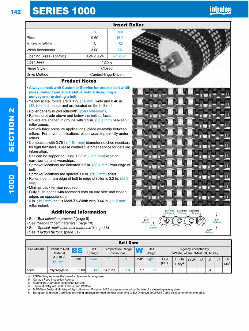
142 SERIES 1000S
EC
TIO
N 2
1000
Insert Rollerin. mm
Pitch 0.60 15.2
Minimum Width 6 152
Width Increments 3.00 76
Opening Sizes (approx.) 0.24 x 0.24 6.1 x 6.1
Open Area 12.5%
Hinge Style Closed
Drive Method Center/Hinge-Driven
Product Notes• Always check with Customer Service for precise belt width
measurement and stock status before designing a conveyor or ordering a belt.
• Yellow acetal rollers are 0.3 in. (7.6 mm) wide and 0.48 in. (12.1 mm) diameter and are located on the belt rod.
• Roller density is 240 rollers/ft2 (2580 rollers/m2).• Rollers protrude above and below the belt surfaces.• Rollers are spaced in groups with 1.5 in. (38.1 mm) between
roller zones.• For low back pressure applications, place wearstrip between
rollers. For driven applications, place wearstrip directly under rollers.
• Compatible with 0.75 in. (19.1 mm) diameter notched nosebars for tight transfers. Please contact customer service for detailed information.
• Belt can be supported using 1.38 in. (35.1 mm) wide or narrower parallel wearstrips.
• Sprocket locations are indented 1.5 in. (38.1 mm) from edge of belt.
• Sprocket locations are spaced 3.0 in. (76.2 mm) apart.• Roller indent from edge of belt to edge of roller is 2.2 in. (55.9
mm).• Minimal back tension required.• Fully flush edges with recessed rods on one side and closed
edges on opposite side.• 6 in. (152 mm) belt is Mold-To-Width with 0.44 in. (11.2 mm)
roller indent.
Additional Information• See “Belt selection process” (page 5)• See “Standard belt materials” (page 18)• See “Special application belt materials” (page 18)• See “Friction factors” (page 31)
0.35"(8.9 mm)
0.17"(4.3 mm)
0.60" NOM.(15.2 mm)
0.60" NOM.(15.2 mm)
0.60" NOM.(15.2 mm)
0.24"(6.1 mm)
0.48"(12.2 mm)
Belt DataBelt Material Standard Rod
MaterialØ 0.18 in. (4.6 mm)
BS Belt Strength
Temperature Range (continuous) W Belt
WeightAgency Acceptability
1-White, 2-Blue, 3-Natural, 4-Grey
lb/ft kg/m °F °C lb/ft² kg/m² FDA (USA)
USDADairya
CFAb Ac Jd Ze EU MCf
Acetal Polypropylene 1000 1490 34 to 200 1 to 93 1.7 8.3 • 3
a. USDA Dairy requires the use of a clean-in-place-system.b. Canada Food Inspection Agencyc. Australian Quarantine Inspection Serviced. Japan Ministry of Health, Labour, and Welfaree. MAF-New Zealand Ministry of Agriculture and Forestry. MAF acceptance requires the use of a clean-in-place system.f. European Migration Certificate providing approval for food contact according to EU Directive 2002/72/EC and all its amendments to date.
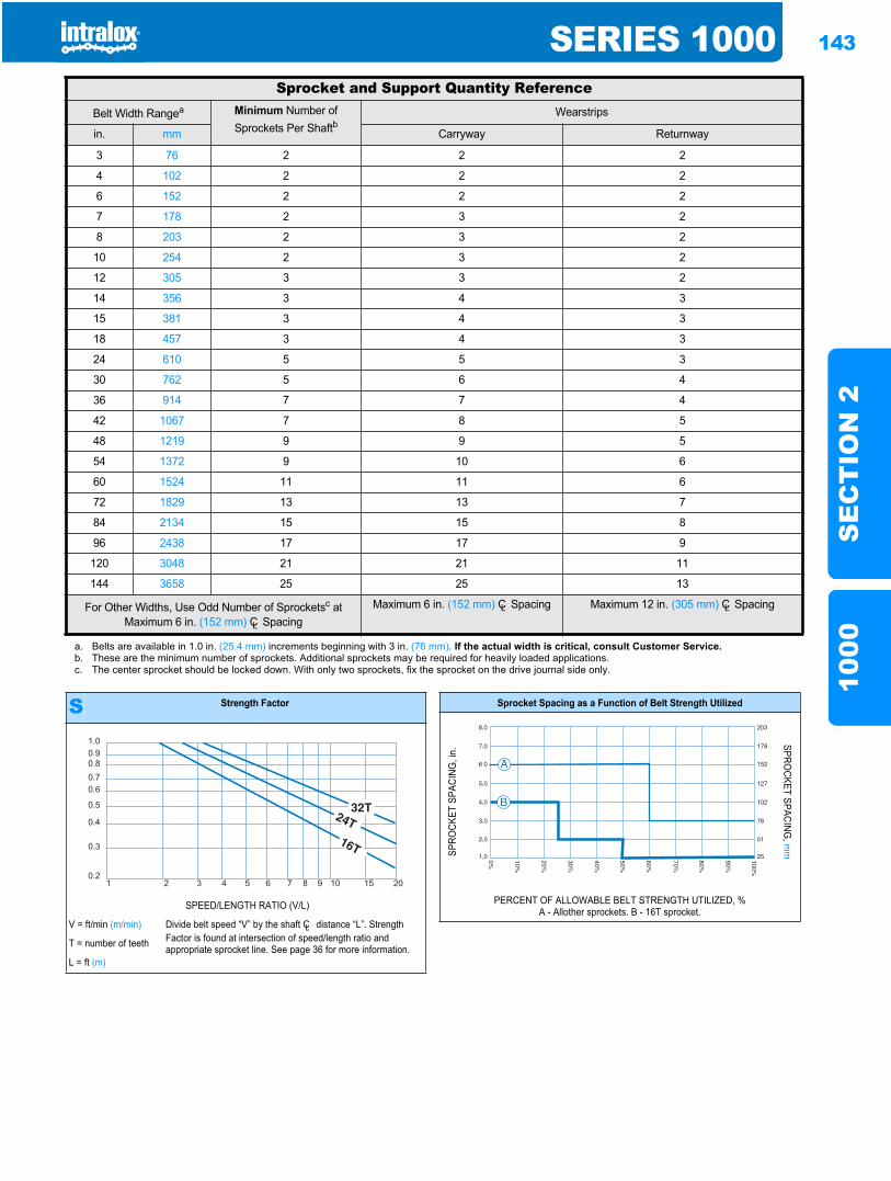
SERIES 1000 143
SE
CT
ION
210
00
Sprocket and Support Quantity ReferenceBelt Width Rangea Minimum Number of
Sprockets Per ShaftbWearstrips
in. mm Carryway Returnway
3 76 2 2 2
4 102 2 2 2
6 152 2 2 2
7 178 2 3 2
8 203 2 3 2
10 254 2 3 2
12 305 3 3 2
14 356 3 4 3
15 381 3 4 3
18 457 3 4 3
24 610 5 5 3
30 762 5 6 4
36 914 7 7 4
42 1067 7 8 5
48 1219 9 9 5
54 1372 9 10 6
60 1524 11 11 6
72 1829 13 13 7
84 2134 15 15 8
96 2438 17 17 9
120 3048 21 21 11
144 3658 25 25 13
For Other Widths, Use Odd Number of Sprocketsc at Maximum 6 in. (152 mm) CL Spacing
Maximum 6 in. (152 mm) CL Spacing Maximum 12 in. (305 mm) CL Spacing
a. Belts are available in 1.0 in. (25.4 mm) increments beginning with 3 in. (76 mm). If the actual width is critical, consult Customer Service.b. These are the minimum number of sprockets. Additional sprockets may be required for heavily loaded applications.c. The center sprocket should be locked down. With only two sprockets, fix the sprocket on the drive journal side only.
S Strength Factor
SPEED/LENGTH RATIO (V/L)
V = ft/min (m/min) Divide belt speed “V” by the shaft CL distance “L”. Strength Factor is found at intersection of speed/length ratio and appropriate sprocket line. See page 36 for more information.T = number of teeth
L = ft (m)
1.00.90.80.70.6
0.5
0.4
0.3
0.21 2 3 4 5 6 7 8 9 10 15 20
Sprocket Spacing as a Function of Belt Strength Utilized
SPRO
CKET
SPA
CING
, in.
SPROCKET SPACING
, mm
PERCENT OF ALLOWABLE BELT STRENGTH UTILIZED, %A - Allother sprockets. B - 16T sprocket.
B
A
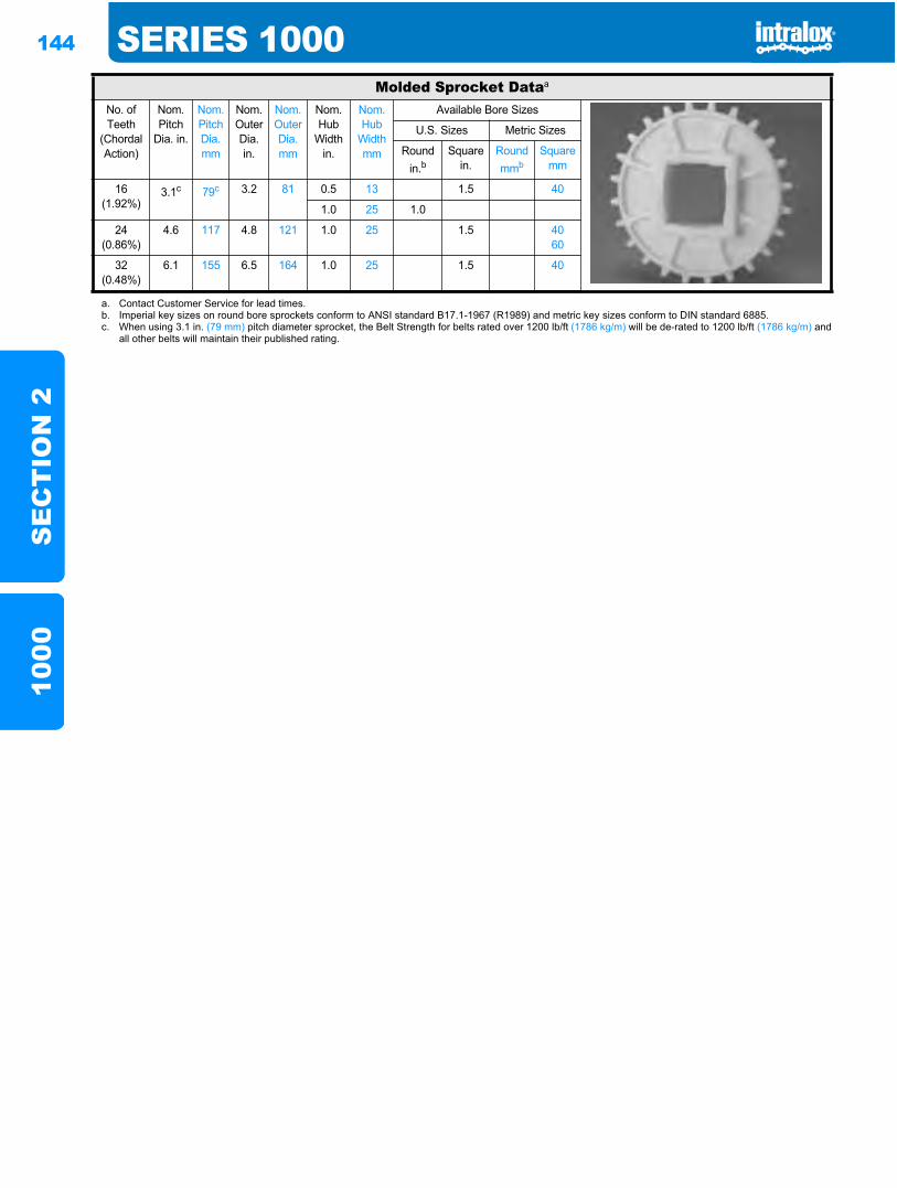
144 SERIES 1000S
EC
TIO
N 2
1000
Molded Sprocket Dataa
No. of Teeth
(Chordal Action)
Nom. Pitch
Dia. in.
Nom. Pitch Dia. mm
Nom. Outer Dia. in.
Nom. Outer Dia.mm
Nom. Hub
Width in.
Nom. Hub
Width mm
Available Bore Sizes
U.S. Sizes Metric Sizes
Round in.b
Square in.
Round mmb
Square mm
16(1.92%)
3.1c 79c 3.2 81 0.5 13 1.5 40
1.0 25 1.0
24(0.86%)
4.6 117 4.8 121 1.0 25 1.5 4060
32(0.48%)
6.1 155 6.5 164 1.0 25 1.5 40
a. Contact Customer Service for lead times.b. Imperial key sizes on round bore sprockets conform to ANSI standard B17.1-1967 (R1989) and metric key sizes conform to DIN standard 6885.c. When using 3.1 in. (79 mm) pitch diameter sprocket, the Belt Strength for belts rated over 1200 lb/ft (1786 kg/m) will be de-rated to 1200 lb/ft (1786 kg/m) and
all other belts will maintain their published rating.
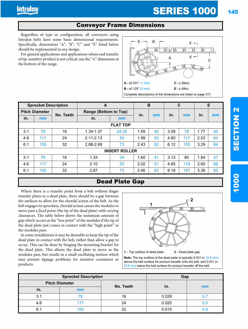
SERIES 1000 145
SE
CT
ION
210
00
Regardless of type or configuration, all conveyors usingIntralox belts have some basic dimensional requirements.Specifically, dimensions “A”, “B”, “C” and “E” listed belowshould be implemented in any design.
For general applications and applications where end transferof tip-sensitive product is not critical, use the “A” dimension atthe bottom of the range.
Where there is a transfer point from a belt without fingertransfer plates to a dead plate, there should be a gap betweenthe surfaces to allow for the chordal action of the belt. As thebelt engages its sprockets, chordal action causes the modules tomove past a fixed point (the tip of the dead plate) with varyingclearances. The table below shows the minimum amount ofgap which occurs at the “low point” of the modules if the tip ofthe dead plate just comes in contact with the “high point” asthe modules pass.
In some installations it may be desirable to keep the tip of thedead plate in contact with the belt, rather than allow a gap tooccur. This can be done by hinging the mounting bracket forthe dead plate. This allows the dead plate to move as themodules pass, but results in a small oscillating motion whichmay present tippage problems for sensitive containers orproducts.
Conveyor Frame Dimensions
A - ±0.031” (1 mm) C - ± (Max)
B - ±0.125” (3 mm) E - ± (Min)
Complete descriptions of the dimensions are listed on page 317.
Sprocket Description A B C EPitch Diameter
No. TeethRange (Bottom to Top)
in. mm in. mm in. mmin. mm in. mm
FLAT TOP3.1 79 16 1.34-1.37 24-35 1.59 40 3.08 78 1.77 454.6 117 24 2.11-2.13 54 1.99 50 4.60 117 2.53 646.1 155 32 2.88-2.89 73 2.43 62 6.12 155 3.29 84
INSERT ROLLER3.1 79 16 1.33 34 1.60 41 3.13 80 1.84 474.6 117 24 2.10 53 2.02 51 4.65 118 2.60 666.1 155 32 2.87 73 2.46 62 6.18 157 3.36 85
Dead Plate Gap
1 - Top surface of dead plate 2 - Dead plate gap
Note: The top surface of the dead plate is typically 0.031 in. (0.8 mm)above the belt surface for product transfer onto the belt, and 0.031 in. (0.8 mm) below the belt surface for product transfer off the belt.
21
Sprocket Description GapPitch Diameter
No. Teeth in. mmin. mm3.1 79 16 0.029 0.74.6 117 24 0.020 0.56.1 155 32 0.015 0.4

146 SERIES 1000S
EC
TIO
N 2
1000
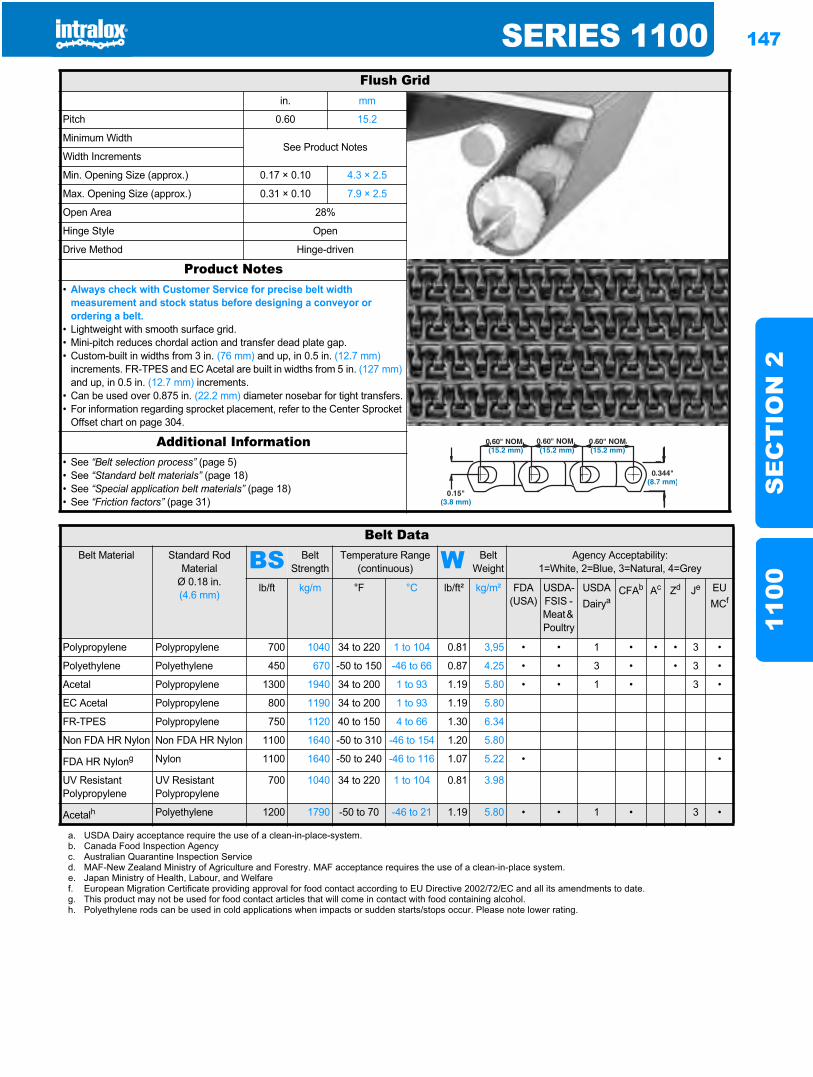
SERIES 1100 147
SE
CT
ION
211
00
Series 11001100
Flush Gridin. mm
Pitch 0.60 15.2
Minimum WidthSee Product Notes
Width Increments
Min. Opening Size (approx.) 0.17 × 0.10 4.3 × 2.5
Max. Opening Size (approx.) 0.31 × 0.10 7.9 × 2.5
Open Area 28%
Hinge Style Open
Drive Method Hinge-driven
Product Notes• Always check with Customer Service for precise belt width
measurement and stock status before designing a conveyor or ordering a belt.
• Lightweight with smooth surface grid.• Mini-pitch reduces chordal action and transfer dead plate gap.• Custom-built in widths from 3 in. (76 mm) and up, in 0.5 in. (12.7 mm)
increments. FR-TPES and EC Acetal are built in widths from 5 in. (127 mm)and up, in 0.5 in. (12.7 mm) increments.
• Can be used over 0.875 in. (22.2 mm) diameter nosebar for tight transfers.• For information regarding sprocket placement, refer to the Center Sprocket
Offset chart on page 304.
Additional Information• See “Belt selection process” (page 5)• See “Standard belt materials” (page 18)• See “Special application belt materials” (page 18)• See “Friction factors” (page 31)
Belt DataBelt Material Standard Rod
MaterialØ 0.18 in. (4.6 mm)
BS Belt Strength
Temperature Range (continuous) W Belt
WeightAgency Acceptability:
1=White, 2=Blue, 3=Natural, 4=Grey
lb/ft kg/m °F °C lb/ft² kg/m² FDA (USA)
USDA-FSIS - Meat & Poultry
USDADairya
CFAb Ac Zd Je EU MCf
Polypropylene Polypropylene 700 1040 34 to 220 1 to 104 0.81 3,95 • • 1 • • • 3 •
Polyethylene Polyethylene 450 670 -50 to 150 -46 to 66 0.87 4.25 • • 3 • • 3 •
Acetal Polypropylene 1300 1940 34 to 200 1 to 93 1.19 5.80 • • 1 • 3 •
EC Acetal Polypropylene 800 1190 34 to 200 1 to 93 1.19 5.80
FR-TPES Polypropylene 750 1120 40 to 150 4 to 66 1.30 6.34
Non FDA HR Nylon Non FDA HR Nylon 1100 1640 -50 to 310 -46 to 154 1.20 5.80
FDA HR Nylong Nylon 1100 1640 -50 to 240 -46 to 116 1.07 5.22 • •
UV Resistant Polypropylene
UV Resistant Polypropylene
700 1040 34 to 220 1 to 104 0.81 3.98
Acetalh Polyethylene 1200 1790 -50 to 70 -46 to 21 1.19 5.80 • • 1 • 3 •
a. USDA Dairy acceptance require the use of a clean-in-place-system.b. Canada Food Inspection Agencyc. Australian Quarantine Inspection Serviced. MAF-New Zealand Ministry of Agriculture and Forestry. MAF acceptance requires the use of a clean-in-place system.e. Japan Ministry of Health, Labour, and Welfaref. European Migration Certificate providing approval for food contact according to EU Directive 2002/72/EC and all its amendments to date.g. This product may not be used for food contact articles that will come in contact with food containing alcohol.h. Polyethylene rods can be used in cold applications when impacts or sudden starts/stops occur. Please note lower rating.
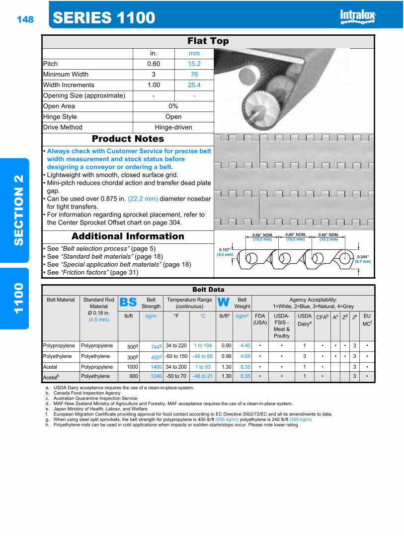
148 SERIES 1100S
EC
TIO
N 2
1100
Flat Topin. mm
Pitch 0.60 15.2Minimum Width 3 76Width Increments 1.00 25.4Opening Size (approximate) - -Open Area 0%Hinge Style OpenDrive Method Hinge-driven
Product Notes• Always check with Customer Service for precise belt
width measurement and stock status before designing a conveyor or ordering a belt.
• Lightweight with smooth, closed surface grid.• Mini-pitch reduces chordal action and transfer dead plate
gap.• Can be used over 0.875 in. (22.2 mm) diameter nosebar
for tight transfers.• For information regarding sprocket placement, refer to
the Center Sprocket Offset chart on page 304.
Additional Information• See “Belt selection process” (page 5)• See “Standard belt materials” (page 18)• See “Special application belt materials” (page 18)• See “Friction factors” (page 31)
Belt DataBelt Material Standard Rod
MaterialØ 0.18 in. (4.6 mm)
BS Belt Strength
Temperature Range (continuous) W Belt
WeightAgency Acceptability:
1=White, 2=Blue, 3=Natural, 4=Grey
lb/ft kg/m °F °C lb/ft² kg/m² FDA (USA)
USDA-FSIS - Meat & Poultry
USDADairya
CFAb Ac Zd Je EUMCf
Polypropylene Polypropylene 500g 744g 34 to 220 1 to 104 0.90 4.40 • • 1 • • • 3 •
Polyethylene Polyethylene 300g 450g -50 to 150 -46 to 66 0.96 4.69 • • 3 • • • 3 •
Acetal Polypropylene 1000 1490 34 to 200 1 to 93 1.30 6.35 • • 1 • 3 •
Acetalh Polyethylene 900 1340 -50 to 70 -46 to 21 1.30 6.35 • • 1 • 3 •
a. USDA Dairy acceptance requires the use of a clean-in-place-system.b. Canada Food Inspection Agencyc. Australian Quarantine Inspection Serviced. MAF-New Zealand Ministry of Agriculture and Forestry. MAF acceptance requires the use of a clean-in-place system.e. Japan Ministry of Health, Labour, and Welfaref. European Migration Certificate providing approval for food contact according to EC Directive 2002/72/EC and all its amendments to date.g. When using steel split sprockets, the belt strength for polypropylene is 400 lb/ft (595 kg/m): polyethylene is 240 lb/ft (360 kg/m)h. Polyethylene rods can be used in cold applications when impacts or sudden starts/stops occur. Please note lower rating.
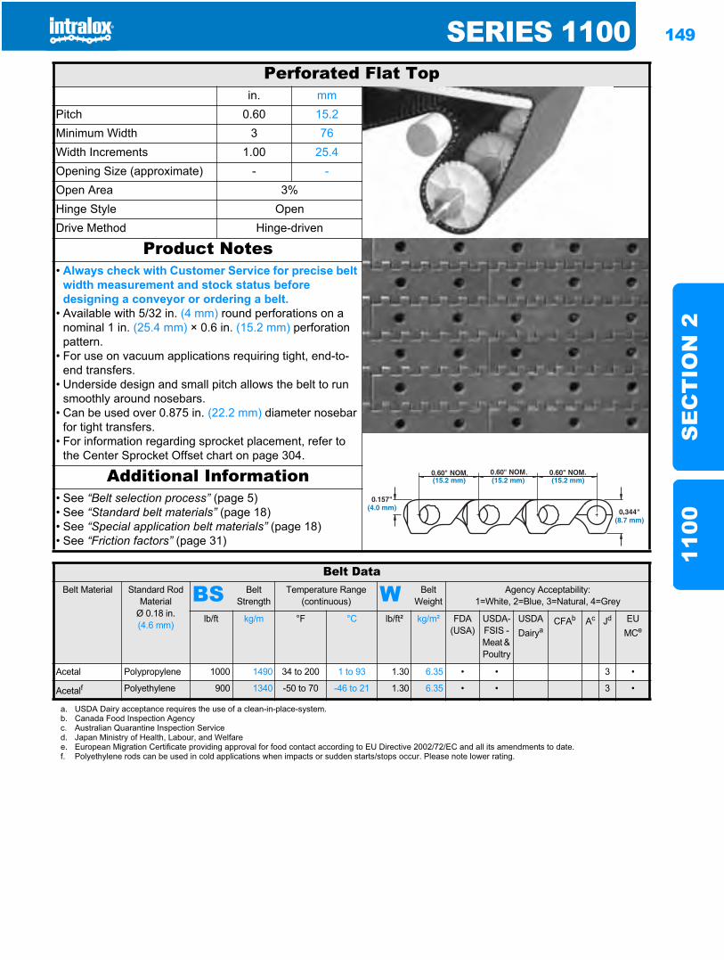
SERIES 1100 149
SE
CT
ION
211
00
Perforated Flat Topin. mm
Pitch 0.60 15.2Minimum Width 3 76Width Increments 1.00 25.4Opening Size (approximate) - -Open Area 3%Hinge Style OpenDrive Method Hinge-driven
Product Notes• Always check with Customer Service for precise belt
width measurement and stock status before designing a conveyor or ordering a belt.
• Available with 5/32 in. (4 mm) round perforations on a nominal 1 in. (25.4 mm) × 0.6 in. (15.2 mm) perforation pattern.
• For use on vacuum applications requiring tight, end-to-end transfers.
• Underside design and small pitch allows the belt to run smoothly around nosebars.
• Can be used over 0.875 in. (22.2 mm) diameter nosebar for tight transfers.
• For information regarding sprocket placement, refer to the Center Sprocket Offset chart on page 304.
Additional Information• See “Belt selection process” (page 5)• See “Standard belt materials” (page 18)• See “Special application belt materials” (page 18)• See “Friction factors” (page 31)
Belt DataBelt Material Standard Rod
MaterialØ 0.18 in. (4.6 mm)
BS Belt Strength
Temperature Range (continuous) W Belt
WeightAgency Acceptability:
1=White, 2=Blue, 3=Natural, 4=Grey
lb/ft kg/m °F °C lb/ft² kg/m² FDA(USA)
USDA-FSIS - Meat & Poultry
USDADairya
CFAb Ac Jd EU MCe
Acetal Polypropylene 1000 1490 34 to 200 1 to 93 1.30 6.35 • • 3 •
Acetalf Polyethylene 900 1340 -50 to 70 -46 to 21 1.30 6.35 • • 3 •
a. USDA Dairy acceptance requires the use of a clean-in-place-system.b. Canada Food Inspection Agencyc. Australian Quarantine Inspection Serviced. Japan Ministry of Health, Labour, and Welfaree. European Migration Certificate providing approval for food contact according to EU Directive 2002/72/EC and all its amendments to date.f. Polyethylene rods can be used in cold applications when impacts or sudden starts/stops occur. Please note lower rating.
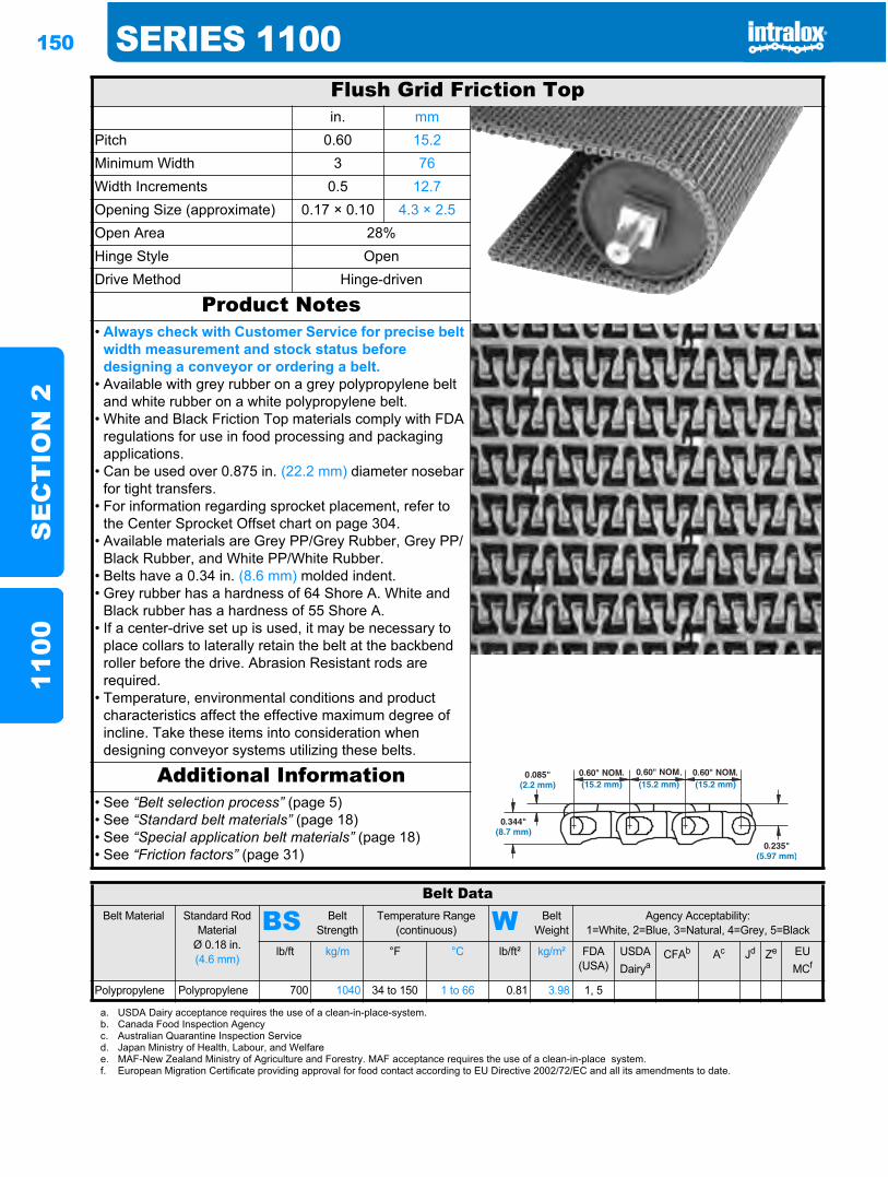
150 SERIES 1100S
EC
TIO
N 2
1100
Flush Grid Friction Topin. mm
Pitch 0.60 15.2Minimum Width 3 76Width Increments 0.5 12.7Opening Size (approximate) 0.17 × 0.10 4.3 × 2.5Open Area 28%Hinge Style OpenDrive Method Hinge-driven
Product Notes• Always check with Customer Service for precise belt
width measurement and stock status before designing a conveyor or ordering a belt.
• Available with grey rubber on a grey polypropylene belt and white rubber on a white polypropylene belt.
• White and Black Friction Top materials comply with FDA regulations for use in food processing and packaging applications.
• Can be used over 0.875 in. (22.2 mm) diameter nosebar for tight transfers.
• For information regarding sprocket placement, refer to the Center Sprocket Offset chart on page 304.
• Available materials are Grey PP/Grey Rubber, Grey PP/Black Rubber, and White PP/White Rubber.
• Belts have a 0.34 in. (8.6 mm) molded indent.• Grey rubber has a hardness of 64 Shore A. White and
Black rubber has a hardness of 55 Shore A.• If a center-drive set up is used, it may be necessary to
place collars to laterally retain the belt at the backbend roller before the drive. Abrasion Resistant rods are required.
• Temperature, environmental conditions and product characteristics affect the effective maximum degree of incline. Take these items into consideration when designing conveyor systems utilizing these belts.
Additional Information• See “Belt selection process” (page 5)• See “Standard belt materials” (page 18)• See “Special application belt materials” (page 18)• See “Friction factors” (page 31)
Belt DataBelt Material Standard Rod
MaterialØ 0.18 in. (4.6 mm)
BS Belt Strength
Temperature Range (continuous) W Belt
WeightAgency Acceptability:
1=White, 2=Blue, 3=Natural, 4=Grey, 5=Black
lb/ft kg/m °F °C lb/ft² kg/m² FDA(USA)
USDADairya
CFAb Ac Jd Ze EU MCf
Polypropylene Polypropylene 700 1040 34 to 150 1 to 66 0.81 3.98 1, 5
a. USDA Dairy acceptance requires the use of a clean-in-place-system.b. Canada Food Inspection Agencyc. Australian Quarantine Inspection Serviced. Japan Ministry of Health, Labour, and Welfaree. MAF-New Zealand Ministry of Agriculture and Forestry. MAF acceptance requires the use of a clean-in-place system.f. European Migration Certificate providing approval for food contact according to EU Directive 2002/72/EC and all its amendments to date.
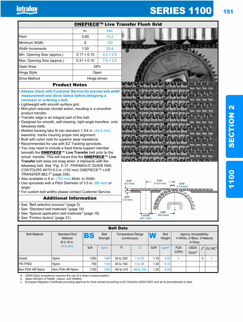
SERIES 1100 151
SE
CT
ION
211
00
ONEPIECE™ Live Transfer Flush Gridin. mm
Pitch 0.60 15.2
Minimum Width 6 152
Width Increments 1.00 25.4
Min. Opening Size (approx.) 0.17 × 0.10 4.3 × 2.5
Max. Opening Size (approx.) 0.31 × 0.10 7.9 × 2.5
Open Area 28%
Hinge Style Open
Drive Method Hinge-driven
Product Notes• Always check with Customer Service for precise belt width
measurement and stock status before designing a conveyor or ordering a belt.
• Lightweight with smooth surface grid.• Mini-pitch reduces chordal action, resulting in a smoother
product transfer.• Transfer edge is an integral part of this belt.• Designed for smooth, self-clearing, right angle transfers onto
takeaway belts.• Molded tracking tabs fit into standard 1-3/4 in. (44.5 mm)
wearstrip tracks insuring proper belt alignment.• Built with nylon rods for superior wear resistance.• Recommended for use with EZ Tracking sprockets.• You may need to include a fixed frame support member
beneath the ONEPIECE™ Live Transfer belt prior to the actual transfer. This will insure that the ONEPIECE™ Live Transfer belt does not snag when it intersects with the takeaway belt. See “Fig. 3–31 PARABOLIC GUIDE RAIL CONTOURS WITH 6.0 in. (152 mm) ONEPIECE™ LIVE TRANSFER BELT” (page 336).
• Also available in 6 in. (152 mm) Mold to Width.• Use sprockets with a Pitch Diameter of 3.5 in. (89 mm) or
larger.• For custom belt widths please contact Customer Service.
Additional Information• See “Belt selection process” (page 5)• See “Standard belt materials” (page 18)• See “Special application belt materials” (page 18)• See “Friction factors” (page 31)
Belt DataBelt Material Standard Rod
MaterialØ 0.18 in. (4.6 mm)
BS Belt Strength
Temperature Range (continuous) W Belt
WeightAgency Acceptability:
1=White, 2=Blue, 3=Natural, 4=Grey
lb/ft kg/m °F °C lb/ft² kg/m² FDA(USA)
USDADairya
Jb EU MCc
Acetal Nylon 1300 1940 34 to 200 1 to 93 1.19 5.80 • 3 •
FR-TPES Nylon 750 1120 40 to 150 4 to 66 1.30 6.34
Non FDA HR Nylon Non FDA HR Nylon 1100 1640 -50 to 310 -46 to 154 1.20 5.80
a. USDA Dairy acceptance requires the use of a clean-in-place-system.b. Japan Ministry of Health, Labour, and Welfarec. European Migration Certificate providing approval for food contact according to EU Directive 2002/72/EC and all its amendments to date.
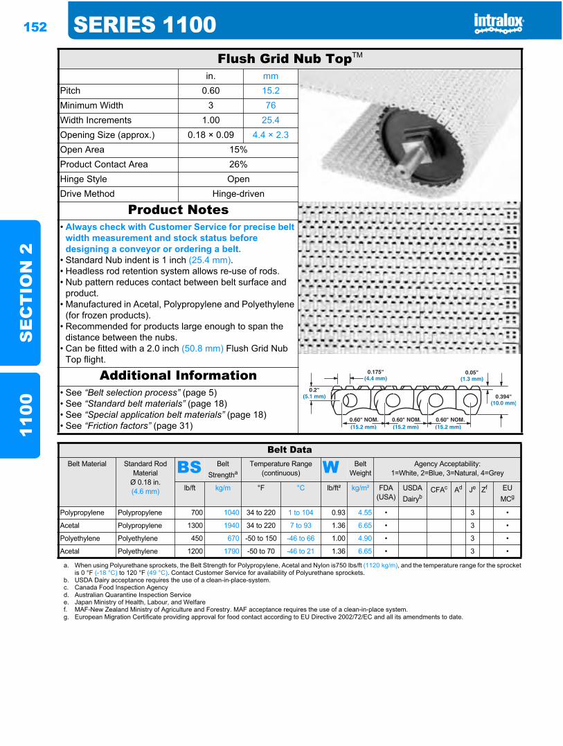
152 SERIES 1100S
EC
TIO
N 2
1100
Flush Grid Nub TopTM
in. mmPitch 0.60 15.2Minimum Width 3 76Width Increments 1.00 25.4Opening Size (approx.) 0.18 × 0.09 4.4 × 2.3Open Area 15%Product Contact Area 26%Hinge Style OpenDrive Method Hinge-driven
Product Notes• Always check with Customer Service for precise belt
width measurement and stock status before designing a conveyor or ordering a belt.
• Standard Nub indent is 1 inch (25.4 mm).• Headless rod retention system allows re-use of rods.• Nub pattern reduces contact between belt surface and
product.• Manufactured in Acetal, Polypropylene and Polyethylene
(for frozen products).• Recommended for products large enough to span the
distance between the nubs.• Can be fitted with a 2.0 inch (50.8 mm) Flush Grid Nub
Top flight.
Additional Information• See “Belt selection process” (page 5)• See “Standard belt materials” (page 18)• See “Special application belt materials” (page 18)• See “Friction factors” (page 31)
Belt DataBelt Material Standard Rod
MaterialØ 0.18 in. (4.6 mm)
BS Belt Strengtha
Temperature Range (continuous) W Belt
WeightAgency Acceptability:
1=White, 2=Blue, 3=Natural, 4=Grey
lb/ft kg/m °F °C lb/ft² kg/m² FDA(USA)
USDADairyb
CFAc Ad Je Zf EU MCg
Polypropylene Polypropylene 700 1040 34 to 220 1 to 104 0.93 4.55 • 3 •
Acetal Polypropylene 1300 1940 34 to 220 7 to 93 1.36 6.65 • 3 •
Polyethylene Polyethylene 450 670 -50 to 150 -46 to 66 1.00 4.90 • 3 •
Acetal Polyethylene 1200 1790 -50 to 70 -46 to 21 1.36 6.65 • 3 •
a. When using Polyurethane sprockets, the Belt Strength for Polypropylene, Acetal and Nylon is750 lbs/ft (1120 kg/m), and the temperature range for the sprocketis 0 °F (-18 °C) to 120 °F (49 °C). Contact Customer Service for availability of Polyurethane sprockets.
b. USDA Dairy acceptance requires the use of a clean-in-place-system.c. Canada Food Inspection Agencyd. Australian Quarantine Inspection Servicee. Japan Ministry of Health, Labour, and Welfaref. MAF-New Zealand Ministry of Agriculture and Forestry. MAF acceptance requires the use of a clean-in-place system.g. European Migration Certificate providing approval for food contact according to EU Directive 2002/72/EC and all its amendments to date.
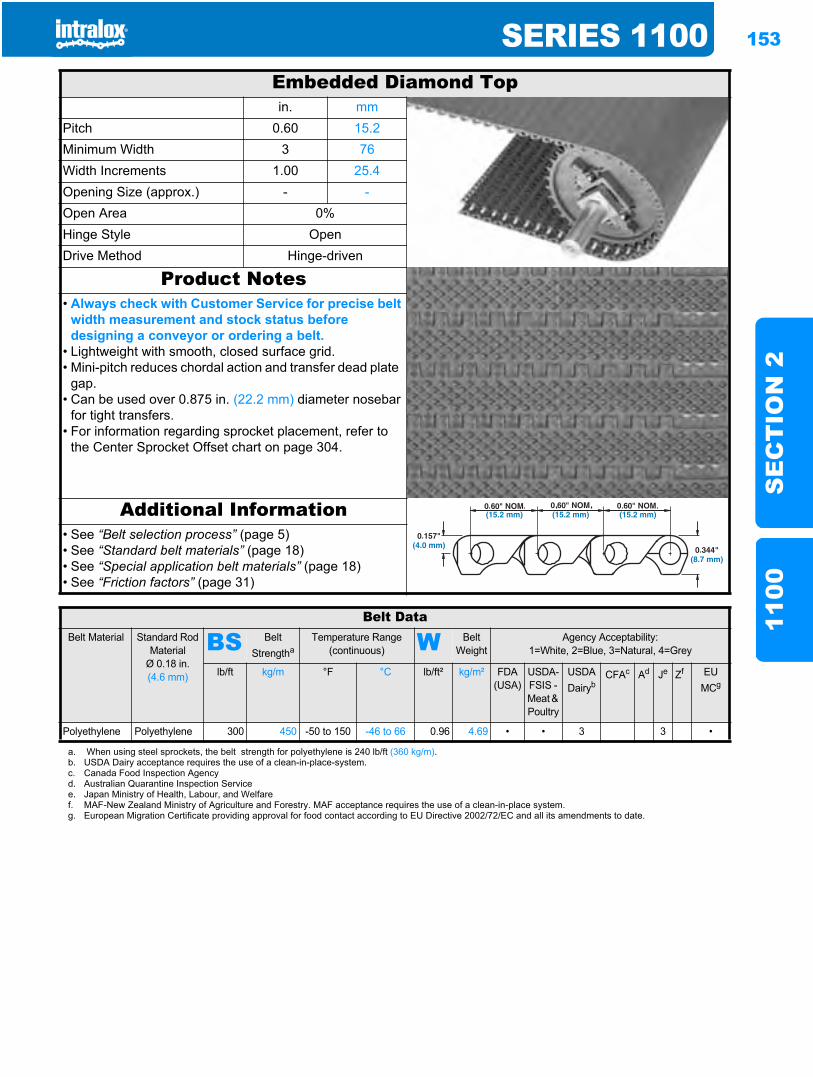
SERIES 1100 153
SE
CT
ION
211
00
Embedded Diamond Topin. mm
Pitch 0.60 15.2Minimum Width 3 76Width Increments 1.00 25.4Opening Size (approx.) - -Open Area 0%Hinge Style OpenDrive Method Hinge-driven
Product Notes• Always check with Customer Service for precise belt
width measurement and stock status before designing a conveyor or ordering a belt.
• Lightweight with smooth, closed surface grid.• Mini-pitch reduces chordal action and transfer dead plate
gap.• Can be used over 0.875 in. (22.2 mm) diameter nosebar
for tight transfers.• For information regarding sprocket placement, refer to
the Center Sprocket Offset chart on page 304.
Additional Information• See “Belt selection process” (page 5)• See “Standard belt materials” (page 18)• See “Special application belt materials” (page 18)• See “Friction factors” (page 31)
Belt DataBelt Material Standard Rod
MaterialØ 0.18 in. (4.6 mm)
BS Belt Strengtha
Temperature Range (continuous) W Belt
WeightAgency Acceptability:
1=White, 2=Blue, 3=Natural, 4=Grey
lb/ft kg/m °F °C lb/ft² kg/m² FDA(USA)
USDA-FSIS - Meat & Poultry
USDADairyb
CFAc Ad Je Zf EU MCg
Polyethylene Polyethylene 300 450 -50 to 150 -46 to 66 0.96 4.69 • • 3 3 •
a. When using steel sprockets, the belt strength for polyethylene is 240 lb/ft (360 kg/m).b. USDA Dairy acceptance requires the use of a clean-in-place-system.c. Canada Food Inspection Agencyd. Australian Quarantine Inspection Servicee. Japan Ministry of Health, Labour, and Welfaref. MAF-New Zealand Ministry of Agriculture and Forestry. MAF acceptance requires the use of a clean-in-place system.g. European Migration Certificate providing approval for food contact according to EU Directive 2002/72/EC and all its amendments to date.
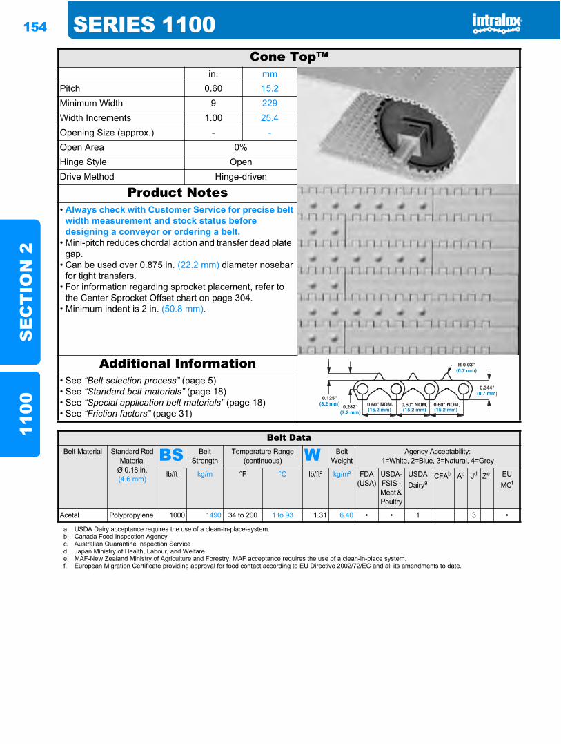
154 SERIES 1100S
EC
TIO
N 2
1100
Cone Top™in. mm
Pitch 0.60 15.2Minimum Width 9 229Width Increments 1.00 25.4Opening Size (approx.) - -Open Area 0%Hinge Style OpenDrive Method Hinge-driven
Product Notes• Always check with Customer Service for precise belt
width measurement and stock status before designing a conveyor or ordering a belt.
• Mini-pitch reduces chordal action and transfer dead plate gap.
• Can be used over 0.875 in. (22.2 mm) diameter nosebar for tight transfers.
• For information regarding sprocket placement, refer to the Center Sprocket Offset chart on page 304.
• Minimum indent is 2 in. (50.8 mm).
Additional Information• See “Belt selection process” (page 5)• See “Standard belt materials” (page 18)• See “Special application belt materials” (page 18)• See “Friction factors” (page 31)
Belt DataBelt Material Standard Rod
MaterialØ 0.18 in. (4.6 mm)
BS Belt Strength
Temperature Range (continuous) W Belt
WeightAgency Acceptability:
1=White, 2=Blue, 3=Natural, 4=Grey
lb/ft kg/m °F °C lb/ft² kg/m² FDA(USA)
USDA-FSIS - Meat & Poultry
USDADairya
CFAb Ac Jd Ze EU MCf
Acetal Polypropylene 1000 1490 34 to 200 1 to 93 1.31 6.40 • • 1 3 •
a. USDA Dairy acceptance requires the use of a clean-in-place-system.b. Canada Food Inspection Agencyc. Australian Quarantine Inspection Serviced. Japan Ministry of Health, Labour, and Welfaree. MAF-New Zealand Ministry of Agriculture and Forestry. MAF acceptance requires the use of a clean-in-place system.f. European Migration Certificate providing approval for food contact according to EU Directive 2002/72/EC and all its amendments to date.
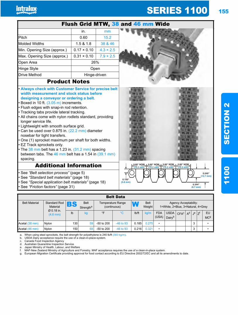
SERIES 1100 155
SE
CT
ION
211
00
Flush Grid MTW, 38 and 46 mm Widein. mm
Pitch 0.60 15.2Molded Widths 1.5 & 1.8 38 & 46Min. Opening Size (approx.) 0.17 × 0.10 4.3 × 2.5Max. Opening Size (approx.) 0.31 × 0.10 7.9 × 2.5Open Area 26%Hinge Style OpenDrive Method Hinge-driven
Product Notes• Always check with Customer Service for precise belt
width measurement and stock status before designing a conveyor or ordering a belt.
• Boxed in 10 ft. (3.05 m) increments.• Flush edges with snap-in rod retention.• Tracking tabs provide lateral tracking.• All chains come with nylon rodlets standard, providing
longer service life.• Lightweight with smooth surface grid.• Can be used over 0.875 in. (22.2 mm) diameter
nosebar for tight transfers.• One (1) sprocket maximum per shaft for both widths.• EZ Track sprockets only.• The 38 mm belt has a 1.23 in. (31.2 mm) spacing
between tabs. The 46 mm belt has a 1.54 in (39.1 mm)spacing.
Additional Information• See “Belt selection process” (page 5)• See “Standard belt materials” (page 18)• See “Special application belt materials” (page 18)• See “Friction factors” (page 31)
Belt DataBelt Material Standard Rod
MaterialØ 0.18 in. (4.6 mm)
BS Belt Strengtha
Temperature Range (continuous) W Belt
WeightAgency Acceptability:
1=White, 2=Blue, 3=Natural, 4=Grey
lb kg °F °C lb/ft kg/m FDA (USA)
USDADairyb
CFAc Ad Je Zf EUMCg
Acetal (38 mm) Nylon 130 59 -50 to 200 -46 to 93 0.185 0.275 • 3 •
Acetal (46 mm) Nylon 150 68 -50 to 200 -46 to 93 0.216 0.321 • 3 •
a. When using steel sprockets, the belt strength for polyethylene is 240 lb/ft (360 kg/m).b. USDA Dairy acceptance require the use of a clean-in-place-system.c. Canada Food Inspection Agencyd. Australian Quarantine Inspection Servicee. Japan Ministry of Health, Labour, and Welfaref. MAF-New Zealand Ministry of Agriculture and Forestry. MAF acceptance requires the use of a clean-in-place system.g. European Migration Certificate providing approval for food contact according to EU Directive 2002/72/EC and all its amendments to date.
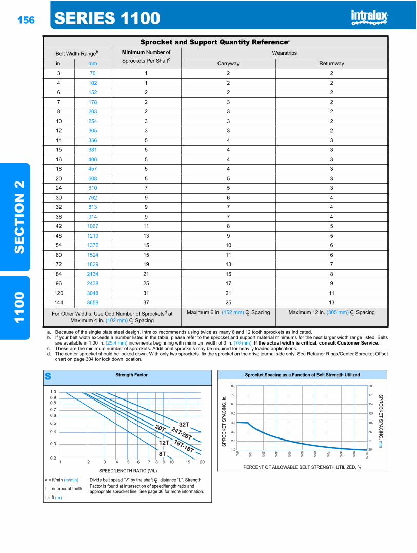
156 SERIES 1100S
EC
TIO
N 2
1100
Sprocket and Support Quantity Referencea
Belt Width Rangeb Minimum Number of Sprockets Per Shaftc
Wearstrips
in. mm Carryway Returnway
3 76 1 2 2
4 102 1 2 2
6 152 2 2 2
7 178 2 3 2
8 203 2 3 2
10 254 3 3 2
12 305 3 3 2
14 356 5 4 3
15 381 5 4 3
16 406 5 4 3
18 457 5 4 3
20 508 5 5 3
24 610 7 5 3
30 762 9 6 4
32 813 9 7 4
36 914 9 7 4
42 1067 11 8 5
48 1219 13 9 5
54 1372 15 10 6
60 1524 15 11 6
72 1829 19 13 7
84 2134 21 15 8
96 2438 25 17 9
120 3048 31 21 11
144 3658 37 25 13
For Other Widths, Use Odd Number of Sprocketsd at Maximum 4 in. (102 mm) CL Spacing
Maximum 6 in. (152 mm) CL Spacing Maximum 12 in. (305 mm) CL Spacing
a. Because of the single plate steel design, Intralox recommends using twice as many 8 and 12 tooth sprockets as indicated.b. If your belt width exceeds a number listed in the table, please refer to the sprocket and support material minimums for the next larger width range listed. Belts
are available in 1.00 in. (25.4 mm) increments beginning with minimum width of 3 in. (76 mm). If the actual width is critical, consult Customer Service.c. These are the minimum number of sprockets. Additional sprockets may be required for heavily loaded applications.d. The center sprocket should be locked down. With only two sprockets, fix the sprocket on the drive journal side only. See Retainer Rings/Center Sprocket Offset
chart on page 304 for lock down location.
S Strength Factor
SPEED/LENGTH RATIO (V/L)
V = ft/min (m/min) Divide belt speed “V” by the shaft CL distance “L”. Strength Factor is found at intersection of speed/length ratio and appropriate sprocket line. See page 36 for more information.T = number of teeth
L = ft (m)
1.00.90.8
0.70.6
0.5
0.4
0.3
0.21 2 3 4 5 6 7 8 9 10 15 20
Sprocket Spacing as a Function of Belt Strength Utilized
SPRO
CKET
SPA
CING
, in.
SPROCKET SPACING
, mm
PERCENT OF ALLOWABLE BELT STRENGTH UTILIZED, %
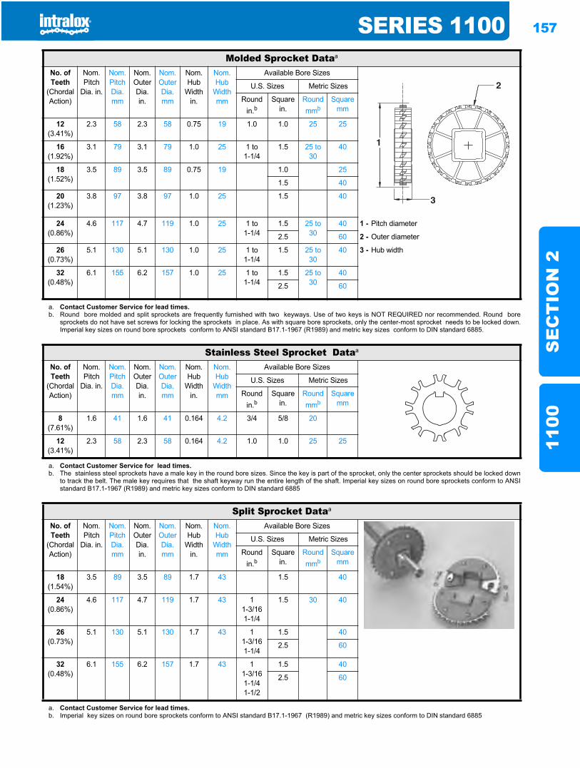
SERIES 1100 157
SE
CT
ION
211
00
Molded Sprocket Dataa
No. of Teeth
(Chordal Action)
Nom. Pitch
Dia. in.
Nom. Pitch Dia. mm
Nom. Outer Dia.in.
Nom. Outer Dia.mm
Nom. Hub
Width in.
Nom. Hub
Width mm
Available Bore Sizes
U.S. Sizes Metric Sizes
Round in.b
Square in.
Round mmb
Square mm
12(3.41%)
2.3 58 2.3 58 0.75 19 1.0 1.0 25 25
16(1.92%)
3.1 79 3.1 79 1.0 25 1 to1-1/4
1.5 25 to 30
40
18(1.52%)
3.5 89 3.5 89 0.75 19 1.0 25
1.5 40
20(1.23%)
3.8 97 3.8 97 1.0 25 1.5 40
24(0.86%)
4.6 117 4.7 119 1.0 25 1 to1-1/4
1.5 25 to 30
40 1 - Pitch diameter
2.5 60 2 - Outer diameter
26(0.73%)
5.1 130 5.1 130 1.0 25 1 to1-1/4
1.5 25 to 30
40 3 - Hub width
32(0.48%)
6.1 155 6.2 157 1.0 25 1 to1-1/4
1.5 25 to 30
40
2.5 60
a. Contact Customer Service for lead times.b. Round bore molded and split sprockets are frequently furnished with two keyways. Use of two keys is NOT REQUIRED nor recommended. Round bore
sprockets do not have set screws for locking the sprockets in place. As with square bore sprockets, only the center-most sprocket needs to be locked down.Imperial key sizes on round bore sprockets conform to ANSI standard B17.1-1967 (R1989) and metric key sizes conform to DIN standard 6885.
Stainless Steel Sprocket Dataa
No. of Teeth
(Chordal Action)
Nom. Pitch
Dia. in.
Nom. Pitch Dia. mm
Nom. Outer Dia.in.
Nom. Outer Dia.mm
Nom. Hub
Width in.
Nom. Hub
Width mm
Available Bore Sizes
U.S. Sizes Metric Sizes
Round in.b
Square in.
Round mmb
Square mm
8(7.61%)
1.6 41 1.6 41 0.164 4.2 3/4 5/8 20
12(3.41%)
2.3 58 2.3 58 0.164 4.2 1.0 1.0 25 25
a. Contact Customer Service for lead times.b. The stainless steel sprockets have a male key in the round bore sizes. Since the key is part of the sprocket, only the center sprockets should be locked down
to track the belt. The male key requires that the shaft keyway run the entire length of the shaft. Imperial key sizes on round bore sprockets conform to ANSIstandard B17.1-1967 (R1989) and metric key sizes conform to DIN standard 6885
Split Sprocket Dataa
No. of Teeth
(Chordal Action)
Nom. Pitch
Dia. in.
Nom. Pitch Dia. mm
Nom. Outer Dia.in.
Nom. Outer Dia.mm
Nom. Hub
Width in.
Nom. Hub
Width mm
Available Bore Sizes
U.S. Sizes Metric Sizes
Round in.b
Square in.
Round mmb
Square mm
18(1.54%)
3.5 89 3.5 89 1.7 43 1.5 40
24(0.86%)
4.6 117 4.7 119 1.7 43 11-3/161-1/4
1.5 30 40
26(0.73%)
5.1 130 5.1 130 1.7 43 11-3/161-1/4
1.5 40
2.5 60
32(0.48%)
6.1 155 6.2 157 1.7 43 11-3/161-1/41-1/2
1.5 40
2.5 60
a. Contact Customer Service for lead times.b. Imperial key sizes on round bore sprockets conform to ANSI standard B17.1-1967 (R1989) and metric key sizes conform to DIN standard 6885
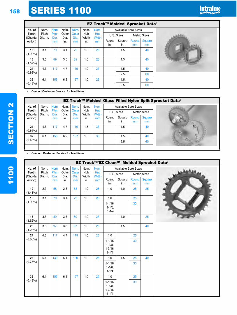
158 SERIES 1100S
EC
TIO
N 2
1100
EZ Track™ Molded Sprocket Dataa
No. of Teeth
(Chordal Action)
Nom. Pitch
Dia. in.
Nom. Pitch Dia. mm
Nom. Outer Dia.in.
Nom. Outer Dia.mm
Nom. Hub
Width in.
Nom. Hub
Width mm
Available Bore Sizes
U.S. Sizes Metric Sizes
Round in.
Square in.
Round mm
Square mm
16(1.92%)
3.1 79 3.1 79 1.0 25 1.5 40
18(1.52%)
3.5 89 3.5 89 1.0 25 1.5 40
24(0.86%)
4.6 117 4.7 119 1.0 25 1.5 40
2.5 60
32(0.48%)
6.1 155 6.2 157 1.0 25 1.5 40
2.5 60
a. Contact Customer Service for lead times.
EZ Track™ Molded Glass Filled Nylon Split Sprocket Dataa
No. of Teeth
(Chordal Action)
Nom. Pitch
Dia. in.
Nom. Pitch Dia. mm
Nom. Outer Dia.in.
Nom. Outer Dia.mm
Nom. Hub
Width in.
Nom. Hub
Width mm
Available Bore Sizes
U.S. Sizes Metric Sizes
Round in.
Square in.
Round mm
Square mm
24(0.86%)
4.6 117 4.7 119 1.5 38 1.5 40
32(0.48%)
6.1 155 6.2 157 1.5 38 1.5 40
2.5 60
a. Contact Customer Service for lead times.
EZ Track™/EZ Clean™ Molded Sprocket Dataa
No. of Teeth
(Chordal Action)
Nom. Pitch
Dia. in.
Nom. Pitch Dia. mm
Nom. Outer Dia.in.
Nom. Outer Dia.mm
Nom. Hub
Width in.
Nom. Hub
Width mm
Available Bore Sizes
U.S. Sizes Metric Sizes
Round in.
Square in.
Round mm
Square mm
12(3.41%)
2.3 58 2.3 58 1.0 25 1.0 1.0 25 25
16(1.92%)
3.1 79 3.1 79 1.0 25 1.0 25
1-1/16, 1-1/8, 1-1/4
30
18(1.52%)
3.5 89 3.5 89 1.0 25 1.0 25
20(1.23%)
3.8 97 3.8 97 1.0 25 1.5 40
24(0.86%)
4.6 117 4.7 119 1.0 25 1.0 25
1-1/16,1-1/8,1-3/16,1-1/4
30
26(0.73%)
5.1 130 5.1 130 1.0 25 1.0 1.5 25 40
1-1/16,1-1/8,1-1/4
30
32(0.48%)
6.1 155 6.2 157 1.0 25 1.0 25
1-1/16,1-1/8,1-3/16,1-1/4
30
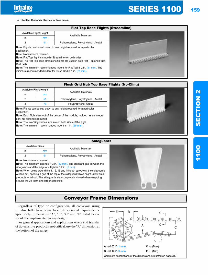
SERIES 1100 159
SE
CT
ION
211
00Regardless of type or configuration, all conveyors using
Intralox belts have some basic dimensional requirements.Specifically, dimensions “A”, “B”, “C” and “E” listed belowshould be implemented in any design.
For general applications and applications where end transferof tip-sensitive product is not critical, use the “A” dimension atthe bottom of the range.
a. Contact Customer Service for lead times.
Flat Top Base Flights (Streamline)Available Flight Height
Available Materialsin. mm
2 51 Polypropylene, Polyethylene, Acetal
Note: Flights can be cut down to any height required for a particular application.Note: No fasteners required.Note: Flat Top flight is smooth (Streamline) on both sides.Note: The Flat Top base streamline flights are used in both Flat Top and Flush Grid belts.Note: The minimum recommended indent for Flat Top is 2 in. (51 mm). The minimum recommended indent for Flush Grid is 1 in. (25 mm).
Flush Grid Nub Top Base Flights (No-Cling)Available Flight Height
Available Materialsin. mm
2 51 Polypropylene, Polyethylene, Acetal
3 76 Polypropylene, Acetal
Note: Flights can be cut down to any height required for a particular application.Note: Each flight rises out of the center of the module, molded as an integral part. No fasteners required.Note: The No-Cling vertical ribs are on both sides of the flight.Note: The minimum recommended indent is 1 in. (25 mm).
SideguardsAvailable Sizes
Available Materialsin. mm
2 51 Polypropylene, Polyethylene, Acetal
Note: No fasteners required.Note: The minimum indent is 1.3 in. (33 mm). The standard gap between the sideguards and the edge of a flight is 0.2 in. (5 mm).Note: When going around the 8, 12, 16 and 18 tooth sprockets, the sideguards will fan out, opening a gap at the top of the sideguard which might allow small products to fall out. The sideguards stay completely closed when wrapping around the 24 tooth and larger sprockets.
Conveyor Frame Dimensions
A - ±0.031” (1 mm) C - ± (Max)
B - ±0.125” (3 mm) E - ± (Min)
Complete descriptions of the dimensions are listed on page 317.
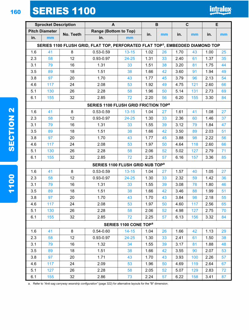
160 SERIES 1100S
EC
TIO
N 2
1100
Sprocket Description A B C EPitch Diameter
No. TeethRange (Bottom to Top)
in. mm in. mm in. mmin. mm in. mm
SERIES 1100 FLUSH GRID, FLAT TOP, PERFORATED FLAT TOPa, EMBEDDED DIAMOND TOP1.6 41 8 0.53-0.59 13-15 1.02 26 1.70 43 1.00 252.3 58 12 0.93-0.97 24-25 1.31 33 2.40 61 1.37 353.1 79 16 1.31 33 1.51 38 3.20 81 1.75 443.5 89 18 1.51 38 1.66 42 3.60 91 1.94 493.8 97 20 1.70 43 1.77 45 3.79 96 2.13 544.6 117 24 2.08 53 1.92 49 4.75 121 2.60 665.1 130 26 2.28 58 1.96 50 5.14 131 2.73 696.1 155 32 2.85 72 2.20 56 6.20 155 3.30 84
SERIES 1100 FLUSH GRID FRICTION TOPa
1.6 41 8 0.53-0.59 13-15 1.04 27 1.61 41 1.08 272.3 58 12 0.93-0.97 24-25 1.30 33 2.36 60 1.46 373.1 79 16 1.31 33 1.55 39 3.12 79 1.84 473.5 89 18 1.51 38 1.66 42 3.50 89 2.03 513.8 97 20 1.70 43 1.77 45 3.88 98 2.22 564.6 117 24 2.08 53 1.97 50 4.64 118 2.60 665.1 130 26 2.28 58 2.06 52 5.02 127 2.79 716.1 155 32 2.85 72 2.25 57 6.16 157 3.36 85
SERIES 1100 FLUSH GRID NUB TOPa
1.6 41 8 0.53-0.59 13-15 1.04 27 1.57 40 1.05 272.3 58 12 0.93-0.97 24-25 1.30 33 2.32 59 1.42 363.1 79 16 1.31 33 1.55 39 3.08 78 1.80 463.5 89 18 1.51 38 1.66 42 3.46 88 1.99 513.8 97 20 1.70 43 1.70 43 3.84 98 2.18 554.6 117 24 2.08 53 1.97 50 4.60 117 2.56 655.1 130 26 2.28 58 2.06 52 4.98 127 2.75 706.1 155 32 2.85 72 2.25 57 6.13 156 3.32 84
SERIES 1100 CONE TOPa
1.6 41 8 0.54-0.60 14-15 1.04 26 1.66 42 1.13 292.3 58 12 0.93-0.97 24-25 1.30 33 2.41 61 1.50 383.1 79 16 1.32 34 1.55 39 3.17 81 1.88 483.5 89 18 1.51 38 1.66 42 3.55 90 2.07 533.8 97 20 1.71 43 1.70 43 3.93 100 2.26 574.6 117 24 2.09 53 1.96 50 4.69 119 2.64 675.1 127 26 2.28 58 2.05 52 5.07 129 2.83 726.1 155 32 2.86 73 2.24 57 6.22 158 3.41 87
a. Refer to “Anti-sag carryway wearstrip configuration” (page 322) for alternative layouts for the "B" dimension.
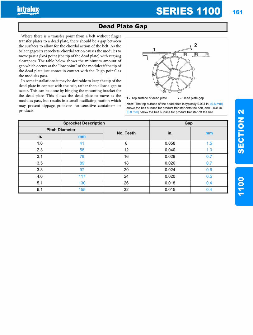
SERIES 1100 161
SE
CT
ION
211
00
Where there is a transfer point from a belt without fingertransfer plates to a dead plate, there should be a gap betweenthe surfaces to allow for the chordal action of the belt. As thebelt engages its sprockets, chordal action causes the modules tomove past a fixed point (the tip of the dead plate) with varyingclearances. The table below shows the minimum amount ofgap which occurs at the “low point” of the modules if the tip ofthe dead plate just comes in contact with the “high point” asthe modules pass.
In some installations it may be desirable to keep the tip of thedead plate in contact with the belt, rather than allow a gap tooccur. This can be done by hinging the mounting bracket forthe dead plate. This allows the dead plate to move as themodules pass, but results in a small oscillating motion whichmay present tippage problems for sensitive containers orproducts.
Dead Plate Gap
1 - Top surface of dead plate 2 - Dead plate gap
Note: The top surface of the dead plate is typically 0.031 in. (0.8 mm)above the belt surface for product transfer onto the belt, and 0.031 in. (0.8 mm) below the belt surface for product transfer off the belt.
21
Sprocket Description GapPitch Diameter
No. Teeth in. mmin. mm1.6 41 8 0.058 1.52.3 58 12 0.040 1.03.1 79 16 0.029 0.73.5 89 18 0.026 0.73.8 97 20 0.024 0.64.6 117 24 0.020 0.55.1 130 26 0.018 0.46.1 155 32 0.015 0.4

162 SERIES 1100S
EC
TIO
N 2
1100
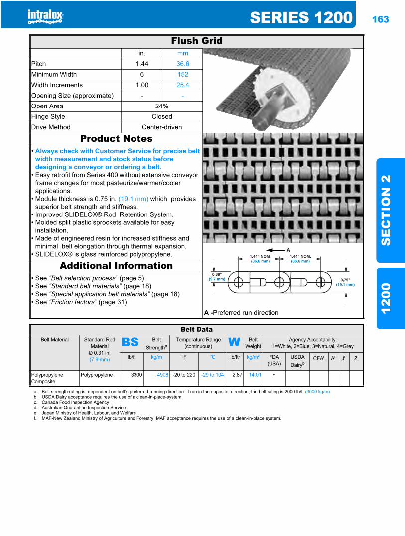
SERIES 1200 163
SE
CT
ION
212
00
Series 12001200
Flush Gridin. mm
Pitch 1.44 36.6Minimum Width 6 152Width Increments 1.00 25.4Opening Size (approximate) - -Open Area 24%Hinge Style ClosedDrive Method Center-driven
Product Notes• Always check with Customer Service for precise belt
width measurement and stock status before designing a conveyor or ordering a belt.
• Easy retrofit from Series 400 without extensive conveyor frame changes for most pasteurize/warmer/cooler applications.
• Module thickness is 0.75 in. (19.1 mm) which provides superior belt strength and stiffness.
• Improved SLIDELOX® Rod Retention System.• Molded split plastic sprockets available for easy
installation.• Made of engineered resin for increased stiffness and
minimal belt elongation through thermal expansion.• SLIDELOX® is glass reinforced polypropylene.
Additional Information• See “Belt selection process” (page 5)• See “Standard belt materials” (page 18)• See “Special application belt materials” (page 18)• See “Friction factors” (page 31)
A -Preferred run direction
Belt DataBelt Material Standard Rod
MaterialØ 0.31 in. (7.9 mm)
BS Belt Strengtha
Temperature Range (continuous) W Belt
WeightAgency Acceptability:
1=White, 2=Blue, 3=Natural, 4=Grey
lb/ft kg/m °F °C lb/ft² kg/m² FDA (USA)
USDADairyb
CFAc Ad Je Zf
Polypropylene Composite
Polypropylene 3300 4908 -20 to 220 -29 to 104 2.87 14.01 •
a. Belt strength rating is dependent on belt’s preferred running direction. If run in the opposite direction, the belt rating is 2000 lb/ft (3000 kg/m).b. USDA Dairy acceptance requires the use of a clean-in-place-system.c. Canada Food Inspection Agencyd. Australian Quarantine Inspection Servicee. Japan Ministry of Health, Labour, and Welfaref. MAF-New Zealand Ministry of Agriculture and Forestry. MAF acceptance requires the use of a clean-in-place system.
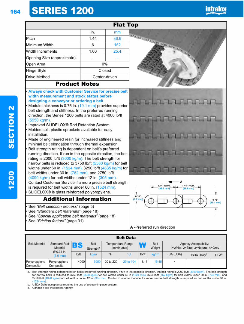
164 SERIES 1200S
EC
TIO
N 2
1200
Flat Topin. mm
Pitch 1.44 36.6Minimum Width 6 152Width Increments 1.00 25.4Opening Size (approximate) - -Open Area 0%Hinge Style ClosedDrive Method Center-driven
Product Notes• Always check with Customer Service for precise belt
width measurement and stock status before designing a conveyor or ordering a belt.
• Module thickness is 0.75 in. (19.1 mm) provides superior belt strength and stiffness. In the preferred running direction, the Series 1200 belts are rated at 4000 lb/ft (5950 kg/m).
• Improved SLIDELOX® Rod Retention System.• Molded split plastic sprockets available for easy
installation.• Made of engineered resin for increased stiffness and
minimal belt elongation through thermal expansion.• Belt strength rating is dependent on belt’s preferred
running direction. If run in the opposite direction, the belt rating is 2000 lb/ft (3000 kg/m). The belt strength for narrow belts is reduced to 3750 lb/ft (5580 kg/m) for belt widths under 60 in. (1524 mm), 3250 lb/ft (4835 kg/m) for belt widths under 30 in. (762 mm), and 2750 lb/ft (4090 kg/m) for belt widths under 12 in. (305 mm).Contact Customer Service if a more precise belt strength is required for belt widths under 60 in. (1524 mm).
• SLIDELOX® is glass reinforced polypropylene.
Additional Information• See “Belt selection process” (page 5)• See “Standard belt materials” (page 18)• See “Special application belt materials” (page 18)• See “Friction factors” (page 31)
A -Preferred run direction
Belt DataBelt Material Standard Rod
MaterialØ 0.31 in. (7.9 mm)
BS Belt Strengtha
Temperature Range (continuous) W Belt
WeightAgency Acceptability:
1=White, 2=Blue, 3=Natural, 4=Grey
lb/ft kg/m °F °C lb/ft² kg/m² FDA (USA) USDA Dairyb CFAc
Polypropylene Composite
Polypropylene Composite
4000 5950 -20 to 220 -29 to 104 3.17 15.45 •
a. Belt strength rating is dependent on belt’s preferred running direction. If run in the opposite direction, the belt rating is 2000 lb/ft (3000 kg/m). The belt strengthfor narrow belts is reduced to 3750 lb/ft (5580 kg/m) for belt widths under 60 in (1524 mm), 3250 lb/ft (762 kg/m) for belt widths under 30 in. (762 mm), and2750 lb/ft (4090 kg/m) for belt widths under 12 in. (305 mm). Contact Customer Service if a more precise belt strength is required for belt widths under 60 in.(1524 mm).
b. USDA Dairy acceptance requires the use of a clean-in-place-system.c. Canada Food Inspection Agency
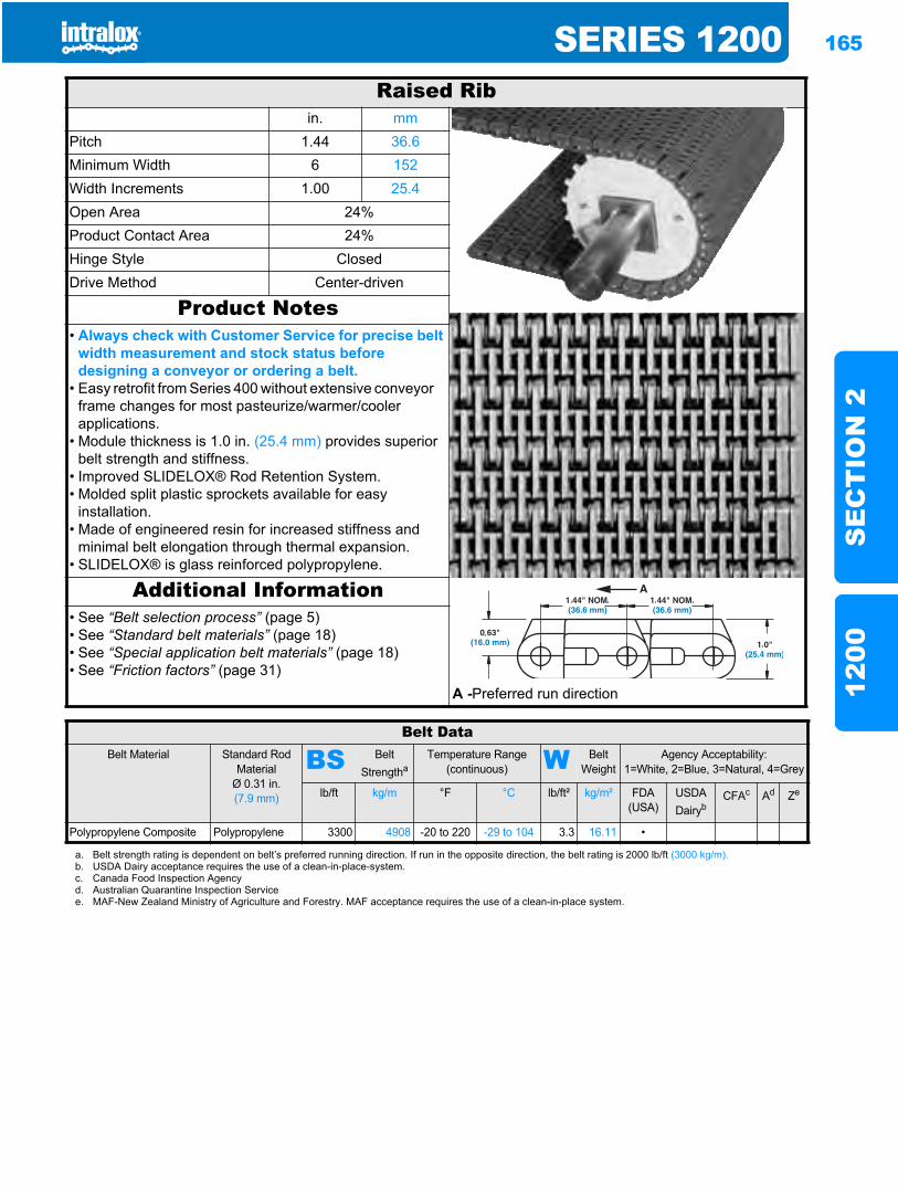
SERIES 1200 165
SE
CT
ION
212
00
Raised Ribin. mm
Pitch 1.44 36.6Minimum Width 6 152Width Increments 1.00 25.4Open Area 24%Product Contact Area 24%Hinge Style ClosedDrive Method Center-driven
Product Notes• Always check with Customer Service for precise belt
width measurement and stock status before designing a conveyor or ordering a belt.
• Easy retrofit from Series 400 without extensive conveyor frame changes for most pasteurize/warmer/cooler applications.
• Module thickness is 1.0 in. (25.4 mm) provides superior belt strength and stiffness.
• Improved SLIDELOX® Rod Retention System.• Molded split plastic sprockets available for easy
installation.• Made of engineered resin for increased stiffness and
minimal belt elongation through thermal expansion.• SLIDELOX® is glass reinforced polypropylene.
Additional Information• See “Belt selection process” (page 5)• See “Standard belt materials” (page 18)• See “Special application belt materials” (page 18)• See “Friction factors” (page 31)
A -Preferred run direction
Belt DataBelt Material Standard Rod
MaterialØ 0.31 in. (7.9 mm)
BS Belt Strengtha
Temperature Range (continuous) W Belt
WeightAgency Acceptability:
1=White, 2=Blue, 3=Natural, 4=Grey
lb/ft kg/m °F °C lb/ft² kg/m² FDA(USA)
USDADairyb
CFAc Ad Ze
Polypropylene Composite Polypropylene 3300 4908 -20 to 220 -29 to 104 3.3 16.11 •
a. Belt strength rating is dependent on belt’s preferred running direction. If run in the opposite direction, the belt rating is 2000 lb/ft (3000 kg/m).b. USDA Dairy acceptance requires the use of a clean-in-place-system.c. Canada Food Inspection Agencyd. Australian Quarantine Inspection Servicee. MAF-New Zealand Ministry of Agriculture and Forestry. MAF acceptance requires the use of a clean-in-place system.
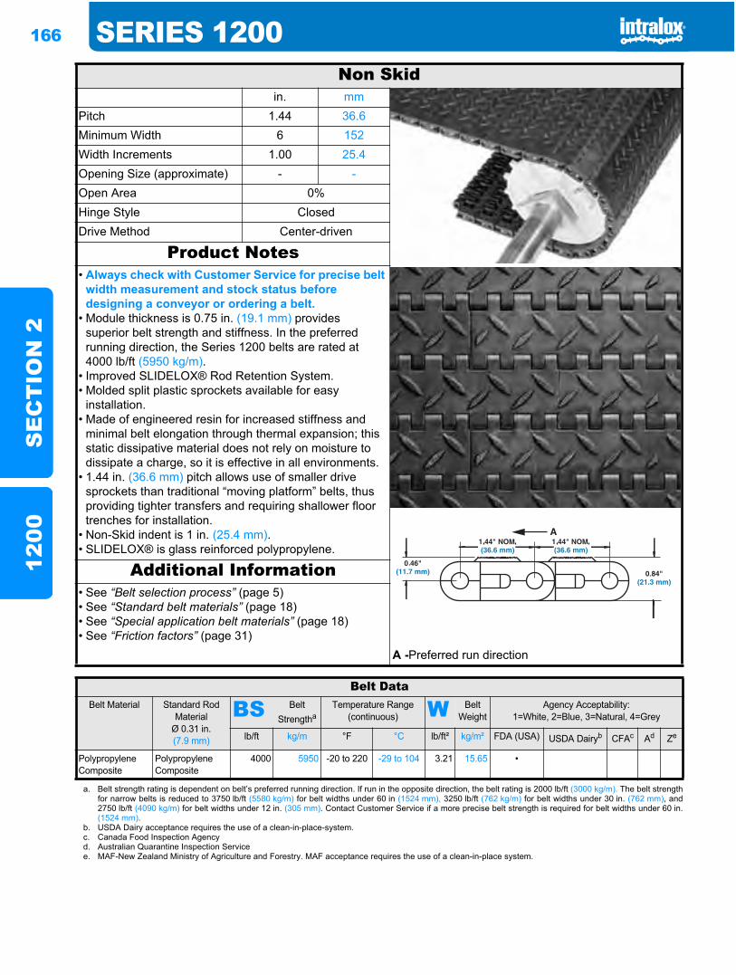
166 SERIES 1200S
EC
TIO
N 2
1200
Non Skidin. mm
Pitch 1.44 36.6Minimum Width 6 152Width Increments 1.00 25.4Opening Size (approximate) - -Open Area 0%Hinge Style ClosedDrive Method Center-driven
Product Notes• Always check with Customer Service for precise belt
width measurement and stock status before designing a conveyor or ordering a belt.
• Module thickness is 0.75 in. (19.1 mm) provides superior belt strength and stiffness. In the preferred running direction, the Series 1200 belts are rated at 4000 lb/ft (5950 kg/m).
• Improved SLIDELOX® Rod Retention System.• Molded split plastic sprockets available for easy
installation.• Made of engineered resin for increased stiffness and
minimal belt elongation through thermal expansion; this static dissipative material does not rely on moisture to dissipate a charge, so it is effective in all environments.
• 1.44 in. (36.6 mm) pitch allows use of smaller drive sprockets than traditional “moving platform” belts, thus providing tighter transfers and requiring shallower floor trenches for installation.
• Non-Skid indent is 1 in. (25.4 mm).• SLIDELOX® is glass reinforced polypropylene.
Additional Information• See “Belt selection process” (page 5)• See “Standard belt materials” (page 18)• See “Special application belt materials” (page 18)• See “Friction factors” (page 31)
A -Preferred run direction
Belt DataBelt Material Standard Rod
MaterialØ 0.31 in. (7.9 mm)
BS Belt Strengtha
Temperature Range (continuous) W Belt
WeightAgency Acceptability:
1=White, 2=Blue, 3=Natural, 4=Grey
lb/ft kg/m °F °C lb/ft² kg/m² FDA (USA) USDA Dairyb CFAc Ad Ze
Polypropylene Composite
Polypropylene Composite
4000 5950 -20 to 220 -29 to 104 3.21 15.65 •
a. Belt strength rating is dependent on belt’s preferred running direction. If run in the opposite direction, the belt rating is 2000 lb/ft (3000 kg/m). The belt strengthfor narrow belts is reduced to 3750 lb/ft (5580 kg/m) for belt widths under 60 in (1524 mm), 3250 lb/ft (762 kg/m) for belt widths under 30 in. (762 mm), and2750 lb/ft (4090 kg/m) for belt widths under 12 in. (305 mm). Contact Customer Service if a more precise belt strength is required for belt widths under 60 in.(1524 mm).
b. USDA Dairy acceptance requires the use of a clean-in-place-system.c. Canada Food Inspection Agencyd. Australian Quarantine Inspection Servicee. MAF-New Zealand Ministry of Agriculture and Forestry. MAF acceptance requires the use of a clean-in-place system.
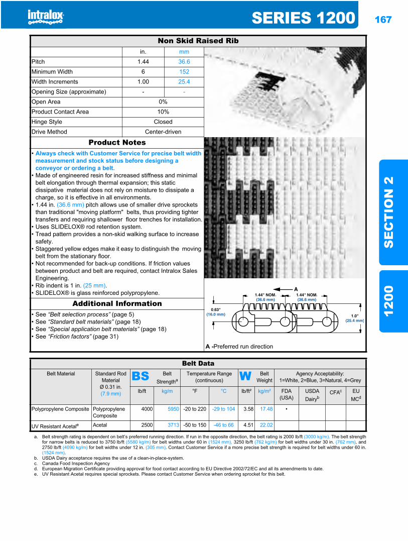
SERIES 1200 167
SE
CT
ION
212
00
Non Skid Raised Ribin. mm
Pitch 1.44 36.6
Minimum Width 6 152
Width Increments 1.00 25.4
Opening Size (approximate) - -
Open Area 0%
Product Contact Area 10%
Hinge Style Closed
Drive Method Center-driven
Product Notes• Always check with Customer Service for precise belt width
measurement and stock status before designing a conveyor or ordering a belt.
• Made of engineered resin for increased stiffness and minimal belt elongation through thermal expansion; this static dissipative material does not rely on moisture to dissipate a charge, so it is effective in all environments.
• 1.44 in. (36.6 mm) pitch allows use of smaller drive sprockets than traditional "moving platform" belts, thus providing tighter transfers and requiring shallower floor trenches for installation.
• Uses SLIDELOX® rod retention system.• Tread pattern provides a non-skid walking surface to increase
safety.• Staggered yellow edges make it easy to distinguish the moving
belt from the stationary floor.• Not recommended for back-up conditions. If friction values
between product and belt are required, contact Intralox Sales Engineering.
• Rib indent is 1 in. (25 mm).• SLIDELOX® is glass reinforced polypropylene.
Additional Information• See “Belt selection process” (page 5)• See “Standard belt materials” (page 18)• See “Special application belt materials” (page 18)• See “Friction factors” (page 31)
A -Preferred run direction
Belt DataBelt Material Standard Rod
MaterialØ 0.31 in. (7.9 mm)
BS Belt Strengtha
Temperature Range (continuous) W Belt
WeightAgency Acceptability:
1=White, 2=Blue, 3=Natural, 4=Grey
lb/ft kg/m °F °C lb/ft² kg/m² FDA(USA)
USDADairyb
CFAc EUMCd
Polypropylene Composite Polypropylene Composite
4000 5950 -20 to 220 -29 to 104 3.58 17.48 •
UV Resistant Acetale Acetal 2500 3713 -50 to 150 -46 to 66 4.51 22.02
a. Belt strength rating is dependent on belt’s preferred running direction. If run in the opposite direction, the belt rating is 2000 lb/ft (3000 kg/m). The belt strengthfor narrow belts is reduced to 3750 lb/ft (5580 kg/m) for belt widths under 60 in (1524 mm), 3250 lb/ft (762 kg/m) for belt widths under 30 in. (762 mm), and2750 lb/ft (4090 kg/m) for belt widths under 12 in. (305 mm). Contact Customer Service if a more precise belt strength is required for belt widths under 60 in.(1524 mm).
b. USDA Dairy acceptance requires the use of a clean-in-place-system.c. Canada Food Inspection Agencyd. European Migration Certificate providing approval for food contact according to EU Directive 2002/72/EC and all its amendments to date.e. UV Resistant Acetal requires special sprockets. Please contact Customer Service when ordering sprocket for this belt.
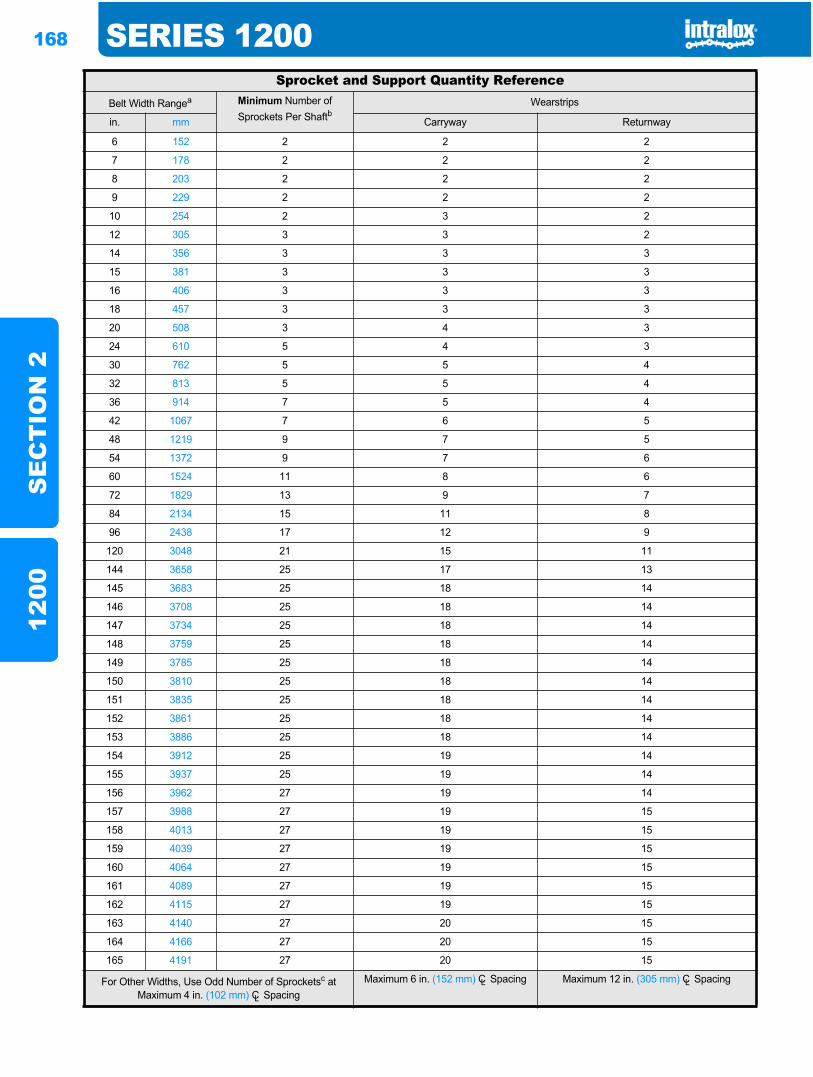
168 SERIES 1200S
EC
TIO
N 2
1200
Sprocket and Support Quantity ReferenceBelt Width Rangea Minimum Number of
Sprockets Per ShaftbWearstrips
in. mm Carryway Returnway
6 152 2 2 2
7 178 2 2 2
8 203 2 2 2
9 229 2 2 2
10 254 2 3 2
12 305 3 3 2
14 356 3 3 3
15 381 3 3 3
16 406 3 3 3
18 457 3 3 3
20 508 3 4 3
24 610 5 4 3
30 762 5 5 4
32 813 5 5 4
36 914 7 5 4
42 1067 7 6 5
48 1219 9 7 5
54 1372 9 7 6
60 1524 11 8 6
72 1829 13 9 7
84 2134 15 11 8
96 2438 17 12 9
120 3048 21 15 11
144 3658 25 17 13
145 3683 25 18 14
146 3708 25 18 14
147 3734 25 18 14
148 3759 25 18 14
149 3785 25 18 14
150 3810 25 18 14
151 3835 25 18 14
152 3861 25 18 14
153 3886 25 18 14
154 3912 25 19 14
155 3937 25 19 14
156 3962 27 19 14
157 3988 27 19 15
158 4013 27 19 15
159 4039 27 19 15
160 4064 27 19 15
161 4089 27 19 15
162 4115 27 19 15
163 4140 27 20 15
164 4166 27 20 15
165 4191 27 20 15
For Other Widths, Use Odd Number of Sprocketsc at Maximum 4 in. (102 mm) CL Spacing
Maximum 6 in. (152 mm) CL Spacing Maximum 12 in. (305 mm) CL Spacing
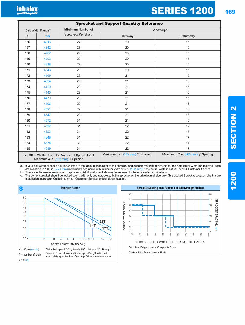
SERIES 1200 169
SE
CT
ION
212
00
166 4216 27 20 15
167 4242 27 20 15
168 4267 29 20 15
169 4293 29 20 16
170 4318 29 20 16
171 4343 29 20 16
172 4369 29 21 16
173 4394 29 21 16
174 4420 29 21 16
175 4445 29 21 16
176 4470 29 21 16
177 4496 29 21 16
178 4521 29 21 16
179 4547 29 21 16
180 4572 31 21 16
181 4597 31 22 17
182 4623 31 22 17
183 4648 31 22 17
184 4674 31 22 17
185 4699 31 22 17
a. If your belt width exceeds a number listed in the table, please refer to the sprocket and support material minimums for the next larger width range listed. Beltsare available in 1.00 in. (25.4 mm) increments beginning with minimum width of 6 in. (152 mm). If the actual width is critical, consult Customer Service.
b. These are the minimum number of sprockets. Additional sprockets may be required for heavily loaded applications.c. The center sprocket should be locked down. With only two sprockets, fix the sprocket on the drive journal side only. See Locked Sprocket Location chart in the
Installation Instruction Guidelines or call Customer Service for lock down location.
Sprocket and Support Quantity ReferenceBelt Width Rangea Minimum Number of
Sprockets Per ShaftbWearstrips
in. mm Carryway Returnway
For Other Widths, Use Odd Number of Sprocketsc at Maximum 4 in. (102 mm) CL Spacing
Maximum 6 in. (152 mm) CL Spacing Maximum 12 in. (305 mm) CL Spacing
S Strength Factor
SPEED/LENGTH RATIO (V/L)
V = ft/min (m/min) Divide belt speed “V” by the shaft CL distance “L”. Strength Factor is found at intersection of speed/length ratio and appropriate sprocket line. See page 36 for more information.T = number of teeth
L = ft (m)
Sprocket Spacing as a Function of Belt Strength Utilized
SPRO
CKET
SPA
CING
, in.
SPROCKET SPACING
, mm
PERCENT OF ALLOWABLE BELT STRENGTH UTILIZED, %
Solid line: Polypropylene Composite Rods
Dashed line: Polypropylene Rods
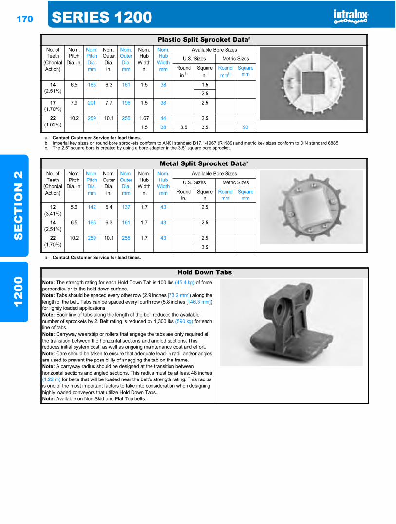
170 SERIES 1200S
EC
TIO
N 2
1200
Plastic Split Sprocket Dataa
No. of Teeth
(Chordal Action)
Nom. Pitch
Dia. in.
Nom. Pitch Dia. mm
Nom. Outer Dia.in.
Nom. Outer Dia.mm
Nom. Hub
Width in.
Nom. Hub
Width mm
Available Bore Sizes
U.S. Sizes Metric Sizes
Round in.b
Square in.c
Round mmb
Square mm
14(2.51%)
6.5 165 6.3 161 1.5 38 1.5
2.5
17(1.70%)
7.9 201 7.7 196 1.5 38 2.5
22(1.02%)
10.2 259 10.1 255 1.67 44 2.5
1.5 38 3.5 3.5 90
a. Contact Customer Service for lead times.b. Imperial key sizes on round bore sprockets conform to ANSI standard B17.1-1967 (R1989) and metric key sizes conform to DIN standard 6885.c. The 2.5" square bore is created by using a bore adapter in the 3.5" square bore sprocket.
Metal Split Sprocket Dataa
No. of Teeth
(Chordal Action)
Nom. Pitch
Dia. in.
Nom. Pitch Dia. mm
Nom. Outer Dia.in.
Nom. Outer Dia.mm
Nom. Hub
Width in.
Nom. Hub
Width mm
Available Bore Sizes
U.S. Sizes Metric Sizes
Round in.
Square in.
Round mm
Square mm
12(3.41%)
5.6 142 5.4 137 1.7 43 2.5
14(2.51%)
6.5 165 6.3 161 1.7 43 2.5
22(1.70%)
10.2 259 10.1 255 1.7 43 2.5
3.5
a. Contact Customer Service for lead times.
Hold Down TabsNote: The strength rating for each Hold Down Tab is 100 lbs (45.4 kg) of force perpendicular to the hold down surface.Note: Tabs should be spaced every other row (2.9 inches [73.2 mm]) along the length of the belt. Tabs can be spaced every fourth row (5.8 inches [146.3 mm])for lightly loaded applications.Note: Each line of tabs along the length of the belt reduces the available number of sprockets by 2. Belt rating is reduced by 1,300 lbs (590 kg) for each line of tabs.Note: Carryway wearstrip or rollers that engage the tabs are only required at the transition between the horizontal sections and angled sections. This reduces initial system cost, as well as ongoing maintenance cost and effort.Note: Care should be taken to ensure that adequate lead-in radii and/or angles are used to prevent the possibility of snagging the tab on the frame.Note: A carryway radius should be designed at the transition between horizontal sections and angled sections. This radius must be at least 48 inches (1.22 m) for belts that will be loaded near the belt’s strength rating. This radius is one of the most important factors to take into consideration when designing highly loaded conveyors that utilize Hold Down Tabs.Note: Available on Non Skid and Flat Top belts.
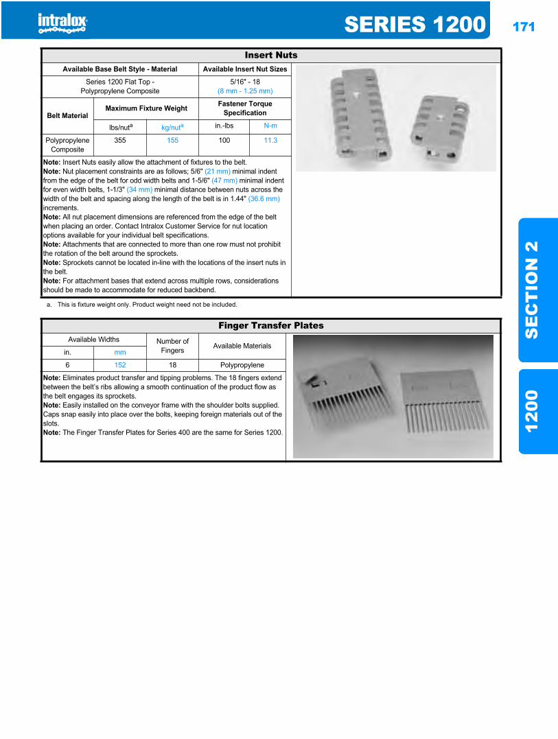
SERIES 1200 171
SE
CT
ION
212
00
Insert NutsAvailable Base Belt Style - Material Available Insert Nut Sizes
Series 1200 Flat Top -Polypropylene Composite
5/16" - 18(8 mm - 1.25 mm)
Belt MaterialMaximum Fixture Weight Fastener Torque
Specification
lbs/nuta kg/nuta in.-lbs N-m
Polypropylene Composite
355 155 100 11.3
Note: Insert Nuts easily allow the attachment of fixtures to the belt.Note: Nut placement constraints are as follows; 5/6" (21 mm) minimal indent from the edge of the belt for odd width belts and 1-5/6" (47 mm) minimal indent for even width belts, 1-1/3" (34 mm) minimal distance between nuts across the width of the belt and spacing along the length of the belt is in 1.44" (36.6 mm)increments.Note: All nut placement dimensions are referenced from the edge of the belt when placing an order. Contact Intralox Customer Service for nut location options available for your individual belt specifications.Note: Attachments that are connected to more than one row must not prohibit the rotation of the belt around the sprockets.Note: Sprockets cannot be located in-line with the locations of the insert nuts in the belt.Note: For attachment bases that extend across multiple rows, considerations should be made to accommodate for reduced backbend.
a. This is fixture weight only. Product weight need not be included.
Finger Transfer PlatesAvailable Widths Number of
Fingers Available Materialsin. mm
6 152 18 Polypropylene
Note: Eliminates product transfer and tipping problems. The 18 fingers extend between the belt’s ribs allowing a smooth continuation of the product flow as the belt engages its sprockets. Note: Easily installed on the conveyor frame with the shoulder bolts supplied. Caps snap easily into place over the bolts, keeping foreign materials out of the slots.Note: The Finger Transfer Plates for Series 400 are the same for Series 1200.
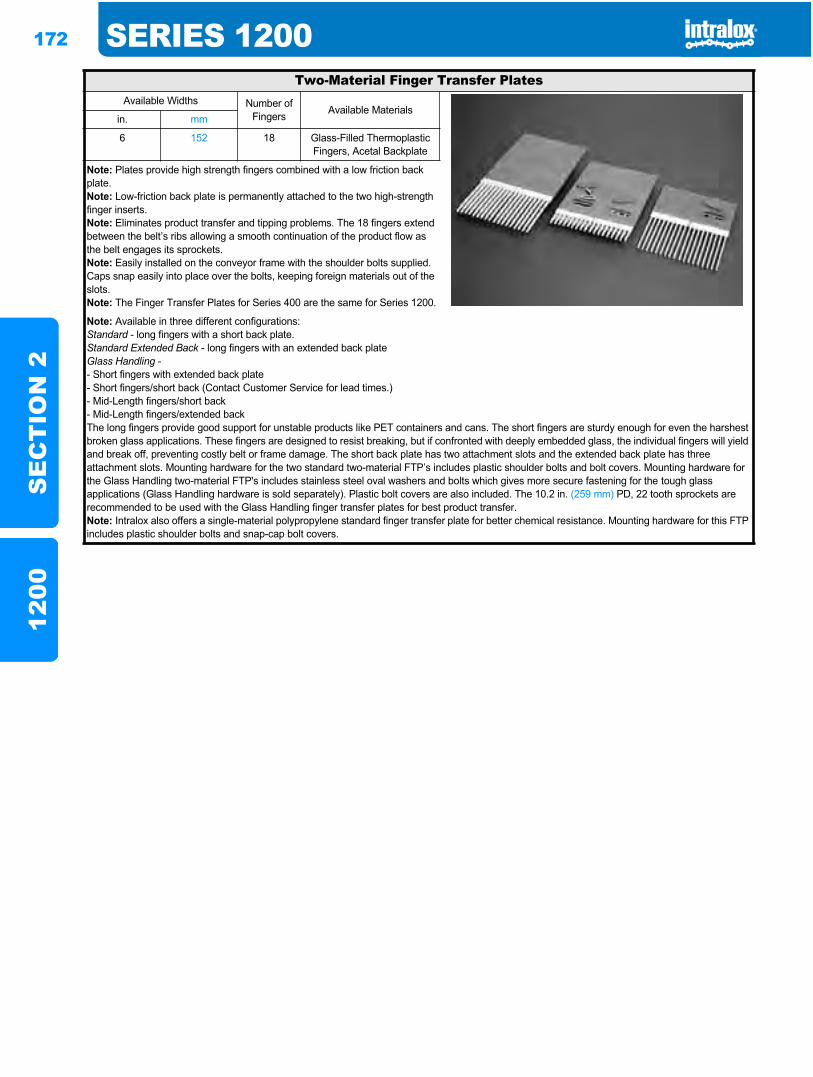
172 SERIES 1200S
EC
TIO
N 2
1200
Two-Material Finger Transfer PlatesAvailable Widths Number of
Fingers Available Materialsin. mm
6 152 18 Glass-Filled Thermoplastic Fingers, Acetal Backplate
Note: Plates provide high strength fingers combined with a low friction back plate.Note: Low-friction back plate is permanently attached to the two high-strength finger inserts.Note: Eliminates product transfer and tipping problems. The 18 fingers extend between the belt’s ribs allowing a smooth continuation of the product flow as the belt engages its sprockets.Note: Easily installed on the conveyor frame with the shoulder bolts supplied. Caps snap easily into place over the bolts, keeping foreign materials out of the slots.Note: The Finger Transfer Plates for Series 400 are the same for Series 1200.
Note: Available in three different configurations:Standard - long fingers with a short back plate.Standard Extended Back - long fingers with an extended back plateGlass Handling -- Short fingers with extended back plate- Short fingers/short back (Contact Customer Service for lead times.)- Mid-Length fingers/short back- Mid-Length fingers/extended backThe long fingers provide good support for unstable products like PET containers and cans. The short fingers are sturdy enough for even the harshest broken glass applications. These fingers are designed to resist breaking, but if confronted with deeply embedded glass, the individual fingers will yield and break off, preventing costly belt or frame damage. The short back plate has two attachment slots and the extended back plate has three attachment slots. Mounting hardware for the two standard two-material FTP’s includes plastic shoulder bolts and bolt covers. Mounting hardware for the Glass Handling two-material FTP's includes stainless steel oval washers and bolts which gives more secure fastening for the tough glass applications (Glass Handling hardware is sold separately). Plastic bolt covers are also included. The 10.2 in. (259 mm) PD, 22 tooth sprockets are recommended to be used with the Glass Handling finger transfer plates for best product transfer.Note: Intralox also offers a single-material polypropylene standard finger transfer plate for better chemical resistance. Mounting hardware for this FTP includes plastic shoulder bolts and snap-cap bolt covers.
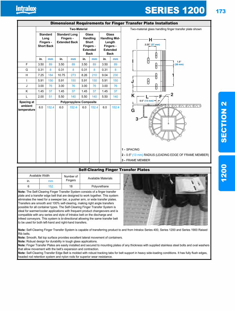
SERIES 1200 173
SE
CT
ION
212
00
Dimensional Requirements for Finger Transfer Plate InstallationTwo-Material Two-material glass handling finger transfer plate shown
Standard Long
Fingers - Short Back
Standard Long Fingers -
Extended Back
Glass Handling
Short Fingers - Extended
Back
Glass Handling Mid-
Length Fingers - Extended
Back
in. mm in. mm in. mm in. mm
F 3.50 89 3.50 89 3.50 89 3.50 89
G 0.31 8 0.31 8 0.31 8 0.31 8
H 7.25 184 10.75 273 8.26 210 9.04 230
I 5.91 150 5.91 150 5.91 150 5.91 150
J 3.00 76 3.00 76 3.00 76 3.00 76
K 1.45 37 1.45 37 1.45 37 1.45 37
L 2.00 51 5.50 140 5.50 140 5.50 140
Spacing at ambient
temperature
Polypropylene Composite
6.0 152.4 6.0 152.4 6.0 152.4 6.0 152.4
1 - SPACING
2 - 0.5" (13 mm) RADIUS (LEADING EDGE OF FRAME MEMBER)
3 - FRAME MEMBER
Self-Clearing Finger Transfer PlatesAvailable Width Number of
Fingers Available Materialsin. mm
6 152 18 Polyurethane
Note: The Self-Clearing Finger Transfer System consists of a finger transfer plate and a transfer edge belt that are designed to work together. This system eliminates the need for a sweeper bar, a pusher arm, or wide transfer plates. Transfers are smooth and 100% self-clearing, making right angle transfers possible for all container types. The Self-Clearing Finger Transfer System is ideal for warmer/cooler applications with frequent product changeovers and is compatible with any series and style of Intralox belt on the discharge and infeed conveyors. This system is bi-directional allowing the same transfer belt to be used for both left-hand and right-hand transfers.
Note: Self-Clearing Finger Transfer System is capable of transferring product to and from Intralox Series 400, Series 1200 and Series 1900 Raised Rib belts.Note: Smooth, flat top surface provides excellent lateral movement of containers.Note: Robust design for durability in tough glass applications.Note: Finger Transfer Plates are easily installed and secured to mounting plates of any thickness with supplied stainless steel bolts and oval washers that allow movement with the belt’s expansion and contraction.Note: Self-Clearing Transfer Edge Belt is molded with robust tracking tabs for belt support in heavy side-loading conditions. It has fully flush edges, headed rod retention system and nylon rods for superior wear resistance.
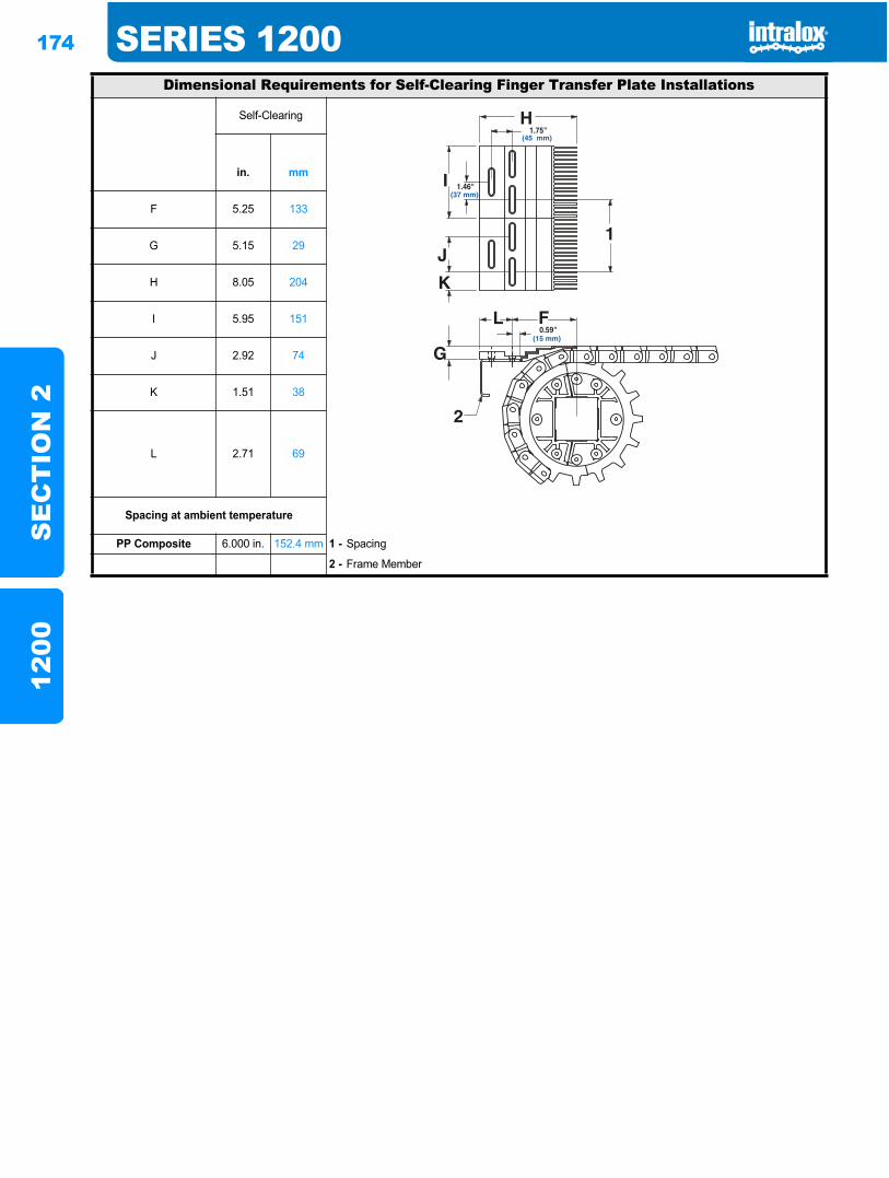
174 SERIES 1200S
EC
TIO
N 2
1200
Dimensional Requirements for Self-Clearing Finger Transfer Plate Installations
Self-Clearing
in. mm
F 5.25 133
G 5.15 29
H 8.05 204
I 5.95 151
J 2.92 74
K 1.51 38
L 2.71 69
Spacing at ambient temperature
PP Composite 6.000 in. 152.4 mm 1 - Spacing
2 - Frame Member
1.75"(45 mm)
0.59"(15 mm)
1.46"(37 mm)
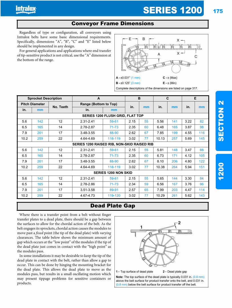
SERIES 1200 175
SE
CT
ION
212
00
Regardless of type or configuration, all conveyors usingIntralox belts have some basic dimensional requirements.Specifically, dimensions “A”, “B”, “C” and “E” listed belowshould be implemented in any design.
For general applications and applications where end transferof tip-sensitive product is not critical, use the “A” dimension atthe bottom of the range.
Where there is a transfer point from a belt without fingertransfer plates to a dead plate, there should be a gap betweenthe surfaces to allow for the chordal action of the belt. As thebelt engages its sprockets, chordal action causes the modules tomove past a fixed point (the tip of the dead plate) with varyingclearances. The table below shows the minimum amount ofgap which occurs at the “low point” of the modules if the tip ofthe dead plate just comes in contact with the “high point” asthe modules pass.
In some installations it may be desirable to keep the tip of thedead plate in contact with the belt, rather than allow a gap tooccur. This can be done by hinging the mounting bracket forthe dead plate. This allows the dead plate to move as themodules pass, but results in a small oscillating motion whichmay present tippage problems for sensitive containers orproducts.
Conveyor Frame Dimensions
A - ±0.031” (1 mm) C - ± (Max)
B - ±0.125” (3 mm) E - ± (Min)
Complete descriptions of the dimensions are listed on page 317.
Sprocket Description A B C EPitch Diameter
No. TeethRange (Bottom to Top)
in. mm in. mm in. mmin. mm in. mm
SERIES 1200 FLUSH GRID, FLAT TOP5.6 142 12 2.31-2.41 59-61 2.15 55 5.56 141 3.22 82
6.5 165 14 2.78-2.87 71-73 2.35 60 6.48 165 3.87 98
7.9 201 17 3.48-3.55 88-90 2.62 67 7.85 199 4.55 116
10.2 259 22 4.64-4.69 118-119 3.02 77 10.13 257 5.69 145
SERIES 1200 RAISED RIB, NON-SKID RAISED RIB5.6 142 12 2.31-2.41 59-61 2.15 55 5.81 148 3.47 88
6.5 165 14 2.78-2.87 71-73 2.35 60 6.73 171 4.12 105
7.9 201 17 3.48-3.55 88-90 2.62 67 8.10 206 4.80 122
10.2 259 22 4.64-4.69 118-119 3.02 77 10.38 264 5.94 151
SERIES 1200 NON SKID5.6 142 12 2.31-2.41 59-61 2.15 55 5.65 144 3.30 84
6.5 165 14 2.78-2.86 71-73 2.34 59 6.56 167 3.76 96
7.9 201 17 3.51-3.58 89-91 2.57 65 7.99 203 4.47 114
10.2 259 22 4.67-4.73 119-120 3.02 77 10.29 261 5.62 143
Dead Plate Gap
1 - Top surface of dead plate 2 - Dead plate gap
Note: The top surface of the dead plate is typically 0.031 in. (0.8 mm)above the belt surface for product transfer onto the belt, and 0.031 in. (0.8 mm) below the belt surface for product transfer off the belt.
21
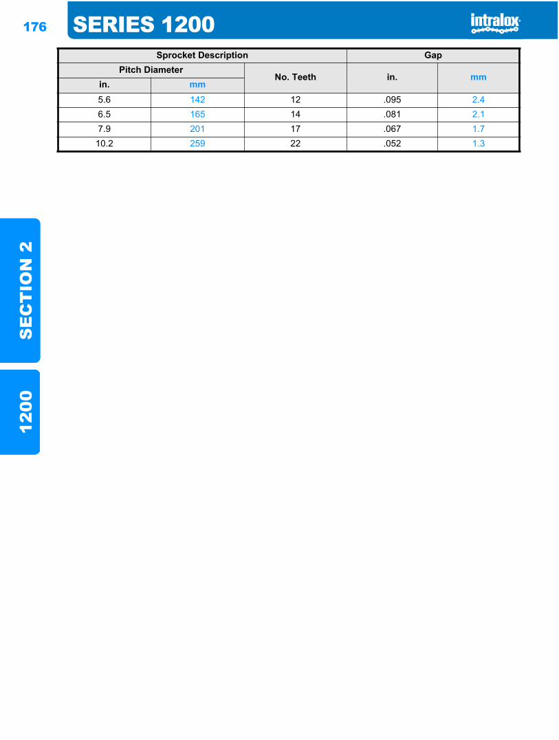
176 SERIES 1200S
EC
TIO
N 2
1200
Sprocket Description GapPitch Diameter
No. Teeth in. mmin. mm5.6 142 12 .095 2.46.5 165 14 .081 2.17.9 201 17 .067 1.7
10.2 259 22 .052 1.3
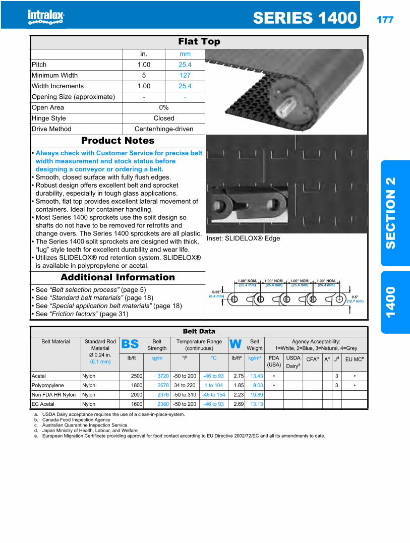
SERIES 1400 177
SE
CT
ION
214
00
Series 14001400
Flat Topin. mm
Pitch 1.00 25.4Minimum Width 5 127Width Increments 1.00 25.4Opening Size (approximate) - -Open Area 0%Hinge Style ClosedDrive Method Center/hinge-driven
Product Notes
Inset: SLIDELOX® Edge
• Always check with Customer Service for precise belt width measurement and stock status before designing a conveyor or ordering a belt.
• Smooth, closed surface with fully flush edges.• Robust design offers excellent belt and sprocket
durability, especially in tough glass applications.• Smooth, flat top provides excellent lateral movement of
containers. Ideal for container handling.• Most Series 1400 sprockets use the split design so
shafts do not have to be removed for retrofits and change overs. The Series 1400 sprockets are all plastic.
• The Series 1400 split sprockets are designed with thick, “lug” style teeth for excellent durability and wear life.
• Utilizes SLIDELOX® rod retention system. SLIDELOX® is available in polypropylene or acetal.
Additional Information• See “Belt selection process” (page 5)• See “Standard belt materials” (page 18)• See “Special application belt materials” (page 18)• See “Friction factors” (page 31)
Belt DataBelt Material Standard Rod
MaterialØ 0.24 in. (6.1 mm)
BS Belt Strength
Temperature Range (continuous) W Belt
WeightAgency Acceptability:
1=White, 2=Blue, 3=Natural, 4=Grey
lb/ft kg/m °F °C lb/ft² kg/m² FDA(USA)
USDADairya
CFAb Ac Jd EU MCe
Acetal Nylon 2500 3720 -50 to 200 -46 to 93 2.75 13.43 • 3 •
Polypropylene Nylon 1800 2678 34 to 220 1 to 104 1.85 9.03 • 3 •
Non FDA HR Nylon Nylon 2000 2976 -50 to 310 -46 to 154 2.23 10.89
EC Acetal Nylon 1600 2380 -50 to 200 -46 to 93 2.69 13.13
a. USDA Dairy acceptance requires the use of a clean-in-place-system.b. Canada Food Inspection Agencyc. Australian Quarantine Inspection Serviced. Japan Ministry of Health, Labour, and Welfaree. European Migration Certificate providing approval for food contact according to EU Directive 2002/72/EC and all its amendments to date.
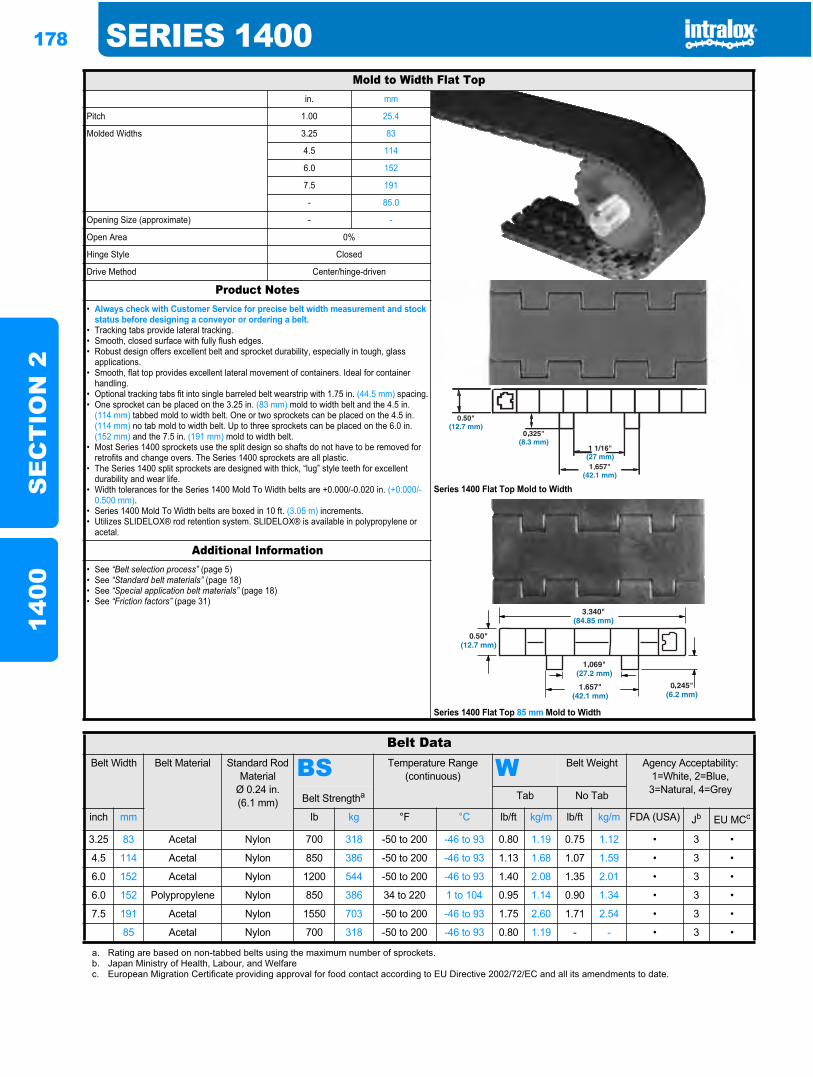
178 SERIES 1400S
EC
TIO
N 2
1400
Mold to Width Flat Topin. mm
Pitch 1.00 25.4
Molded Widths 3.25 83
4.5 114
6.0 152
7.5 191
- 85.0
Opening Size (approximate) - -
Open Area 0%
Hinge Style Closed
Drive Method Center/hinge-driven
Product Notes
Series 1400 Flat Top Mold to Width
Series 1400 Flat Top 85 mm Mold to Width
• Always check with Customer Service for precise belt width measurement and stock status before designing a conveyor or ordering a belt.
• Tracking tabs provide lateral tracking.• Smooth, closed surface with fully flush edges.• Robust design offers excellent belt and sprocket durability, especially in tough, glass
applications.• Smooth, flat top provides excellent lateral movement of containers. Ideal for container
handling.• Optional tracking tabs fit into single barreled belt wearstrip with 1.75 in. (44.5 mm) spacing.• One sprocket can be placed on the 3.25 in. (83 mm) mold to width belt and the 4.5 in.
(114 mm) tabbed mold to width belt. One or two sprockets can be placed on the 4.5 in. (114 mm) no tab mold to width belt. Up to three sprockets can be placed on the 6.0 in. (152 mm) and the 7.5 in. (191 mm) mold to width belt.
• Most Series 1400 sprockets use the split design so shafts do not have to be removed for retrofits and change overs. The Series 1400 sprockets are all plastic.
• The Series 1400 split sprockets are designed with thick, “lug” style teeth for excellent durability and wear life.
• Width tolerances for the Series 1400 Mold To Width belts are +0.000/-0.020 in. (+0.000/-0.500 mm).
• Series 1400 Mold To Width belts are boxed in 10 ft. (3.05 m) increments.• Utilizes SLIDELOX® rod retention system. SLIDELOX® is available in polypropylene or
acetal.
Additional Information• See “Belt selection process” (page 5)• See “Standard belt materials” (page 18)• See “Special application belt materials” (page 18)• See “Friction factors” (page 31)
Belt DataBelt Width Belt Material Standard Rod
MaterialØ 0.24 in. (6.1 mm)
BS Temperature Range (continuous) W Belt Weight Agency Acceptability:
1=White, 2=Blue, 3=Natural, 4=Grey
Belt Strengtha Tab No Tab
inch mm lb kg °F °C lb/ft kg/m lb/ft kg/m FDA (USA) Jb EU MCc
3.25 83 Acetal Nylon 700 318 -50 to 200 -46 to 93 0.80 1.19 0.75 1.12 • 3 •
4.5 114 Acetal Nylon 850 386 -50 to 200 -46 to 93 1.13 1.68 1.07 1.59 • 3 •
6.0 152 Acetal Nylon 1200 544 -50 to 200 -46 to 93 1.40 2.08 1.35 2.01 • 3 •
6.0 152 Polypropylene Nylon 850 386 34 to 220 1 to 104 0.95 1.14 0.90 1.34 • 3 •
7.5 191 Acetal Nylon 1550 703 -50 to 200 -46 to 93 1.75 2.60 1.71 2.54 • 3 •
85 Acetal Nylon 700 318 -50 to 200 -46 to 93 0.80 1.19 - - • 3 •
a. Rating are based on non-tabbed belts using the maximum number of sprockets.b. Japan Ministry of Health, Labour, and Welfarec. European Migration Certificate providing approval for food contact according to EU Directive 2002/72/EC and all its amendments to date.
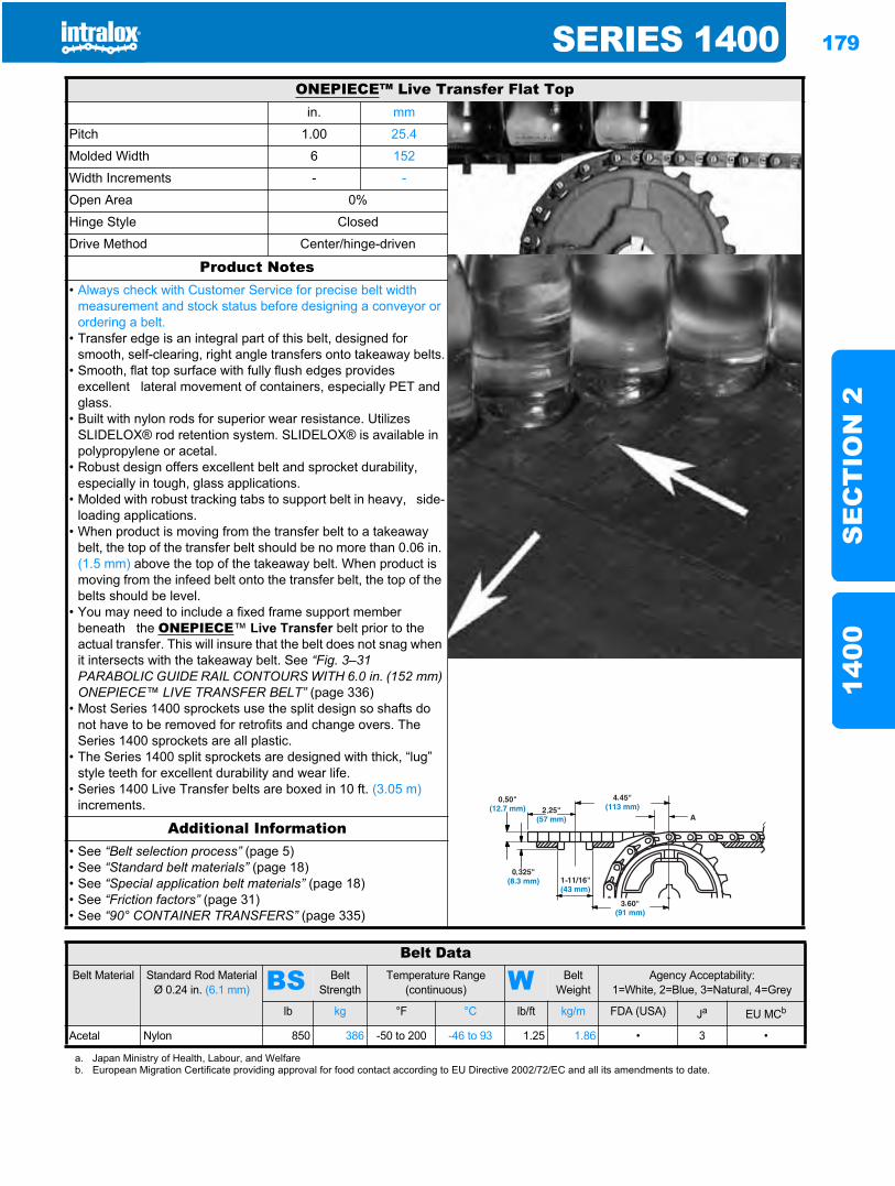
SERIES 1400 179
SE
CT
ION
214
00
ONEPIECE™ Live Transfer Flat Topin. mm
Pitch 1.00 25.4
Molded Width 6 152
Width Increments - -
Open Area 0%
Hinge Style Closed
Drive Method Center/hinge-driven
Product Notes• Always check with Customer Service for precise belt width
measurement and stock status before designing a conveyor or ordering a belt.
• Transfer edge is an integral part of this belt, designed for smooth, self-clearing, right angle transfers onto takeaway belts.
• Smooth, flat top surface with fully flush edges provides excellent lateral movement of containers, especially PET and glass.
• Built with nylon rods for superior wear resistance. Utilizes SLIDELOX® rod retention system. SLIDELOX® is available in polypropylene or acetal.
• Robust design offers excellent belt and sprocket durability, especially in tough, glass applications.
• Molded with robust tracking tabs to support belt in heavy, side-loading applications.
• When product is moving from the transfer belt to a takeaway belt, the top of the transfer belt should be no more than 0.06 in. (1.5 mm) above the top of the takeaway belt. When product is moving from the infeed belt onto the transfer belt, the top of the belts should be level.
• You may need to include a fixed frame support member beneath the ONEPIECE™ Live Transfer belt prior to the actual transfer. This will insure that the belt does not snag when it intersects with the takeaway belt. See “Fig. 3–31 PARABOLIC GUIDE RAIL CONTOURS WITH 6.0 in. (152 mm) ONEPIECE™ LIVE TRANSFER BELT” (page 336)
• Most Series 1400 sprockets use the split design so shafts do not have to be removed for retrofits and change overs. The Series 1400 sprockets are all plastic.
• The Series 1400 split sprockets are designed with thick, “lug” style teeth for excellent durability and wear life.
• Series 1400 Live Transfer belts are boxed in 10 ft. (3.05 m)increments.
Additional Information• See “Belt selection process” (page 5)• See “Standard belt materials” (page 18)• See “Special application belt materials” (page 18)• See “Friction factors” (page 31)• See “90° CONTAINER TRANSFERS” (page 335)
Belt DataBelt Material Standard Rod Material
Ø 0.24 in. (6.1 mm) BS Belt Strength
Temperature Range (continuous) W Belt
WeightAgency Acceptability:
1=White, 2=Blue, 3=Natural, 4=Grey
lb kg °F °C lb/ft kg/m FDA (USA) Ja EU MCb
Acetal Nylon 850 386 -50 to 200 -46 to 93 1.25 1.86 • 3 •
a. Japan Ministry of Health, Labour, and Welfareb. European Migration Certificate providing approval for food contact according to EU Directive 2002/72/EC and all its amendments to date.
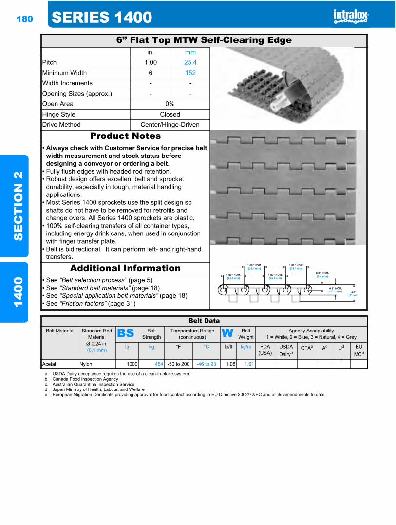
180 SERIES 1400S
EC
TIO
N 2
1400
6” Flat Top MTW Self-Clearing Edgein. mm
Pitch 1.00 25.4Minimum Width 6 152Width Increments - -Opening Sizes (approx.) - -Open Area 0%Hinge Style ClosedDrive Method Center/Hinge-Driven
Product Notes• Always check with Customer Service for precise belt
width measurement and stock status before designing a conveyor or ordering a belt.
• Fully flush edges with headed rod retention.• Robust design offers excellent belt and sprocket
durability, especially in tough, material handling applications.
• Most Series 1400 sprockets use the split design so shafts do not have to be removed for retrofits and change overs. All Series 1400 sprockets are plastic.
• 100% self-clearing transfers of all container types, including energy drink cans, when used in conjunction with finger transfer plate.
• Belt is bidirectional, It can perform left- and right-hand transfers.
Additional Information• See “Belt selection process” (page 5)• See “Standard belt materials” (page 18)• See “Special application belt materials” (page 18)• See “Friction factors” (page 31)
Belt DataBelt Material Standard Rod
MaterialØ 0.24 in. (6.1 mm)
BS Belt Strength
Temperature Range (continuous) W Belt
WeightAgency Acceptability
1 = White, 2 = Blue, 3 = Natural, 4 = Grey
lb kg °F °C lb/ft kg/m FDA (USA)
USDADairya
CFAb Ac Jd EUMCe
Acetal Nylon 1000 454 -50 to 200 -46 to 93 1.08 1.61
a. USDA Dairy acceptance requires the use of a clean-in-place system.b. Canada Food Inspection Agencyc. Australian Quarantine Inspection Serviced. Japan Ministry of Health, Labour, and Welfaree. European Migration Certificate providing approval for food contact according to EU Directive 2002/72/EC and all its amendments to date.
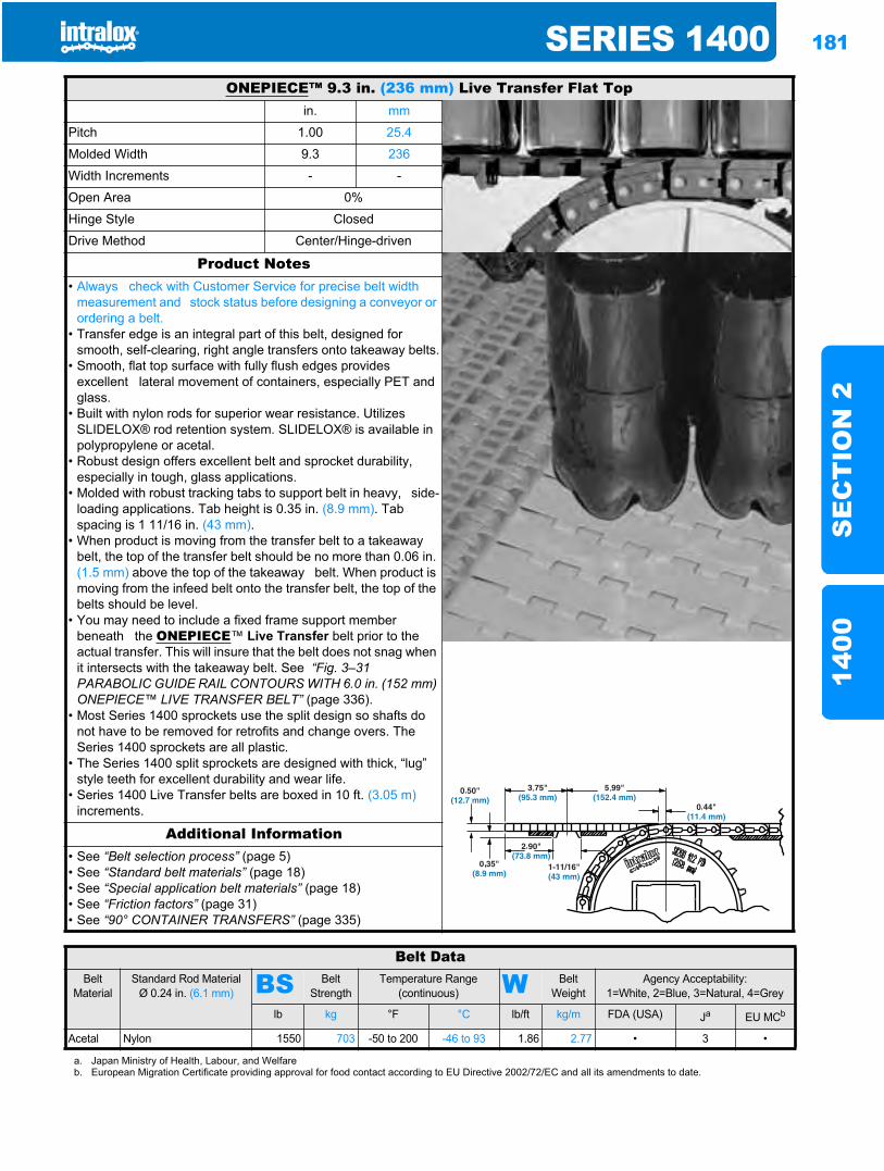
SERIES 1400 181
SE
CT
ION
214
00
ONEPIECE™ 9.3 in. (236 mm) Live Transfer Flat Topin. mm
Pitch 1.00 25.4
Molded Width 9.3 236
Width Increments - -
Open Area 0%
Hinge Style Closed
Drive Method Center/Hinge-driven
Product Notes• Always check with Customer Service for precise belt width
measurement and stock status before designing a conveyor or ordering a belt.
• Transfer edge is an integral part of this belt, designed for smooth, self-clearing, right angle transfers onto takeaway belts.
• Smooth, flat top surface with fully flush edges provides excellent lateral movement of containers, especially PET and glass.
• Built with nylon rods for superior wear resistance. Utilizes SLIDELOX® rod retention system. SLIDELOX® is available in polypropylene or acetal.
• Robust design offers excellent belt and sprocket durability, especially in tough, glass applications.
• Molded with robust tracking tabs to support belt in heavy, side-loading applications. Tab height is 0.35 in. (8.9 mm). Tab spacing is 1 11/16 in. (43 mm).
• When product is moving from the transfer belt to a takeaway belt, the top of the transfer belt should be no more than 0.06 in. (1.5 mm) above the top of the takeaway belt. When product is moving from the infeed belt onto the transfer belt, the top of the belts should be level.
• You may need to include a fixed frame support member beneath the ONEPIECE™ Live Transfer belt prior to the actual transfer. This will insure that the belt does not snag when it intersects with the takeaway belt. See “Fig. 3–31 PARABOLIC GUIDE RAIL CONTOURS WITH 6.0 in. (152 mm) ONEPIECE™ LIVE TRANSFER BELT” (page 336).
• Most Series 1400 sprockets use the split design so shafts do not have to be removed for retrofits and change overs. The Series 1400 sprockets are all plastic.
• The Series 1400 split sprockets are designed with thick, “lug” style teeth for excellent durability and wear life.
• Series 1400 Live Transfer belts are boxed in 10 ft. (3.05 m)increments.
Additional Information• See “Belt selection process” (page 5)• See “Standard belt materials” (page 18)• See “Special application belt materials” (page 18)• See “Friction factors” (page 31)• See “90° CONTAINER TRANSFERS” (page 335)
Belt DataBelt
MaterialStandard Rod Material
Ø 0.24 in. (6.1 mm) BS Belt Strength
Temperature Range (continuous) W Belt
WeightAgency Acceptability:
1=White, 2=Blue, 3=Natural, 4=Grey
lb kg °F °C lb/ft kg/m FDA (USA) Ja EU MCb
Acetal Nylon 1550 703 -50 to 200 -46 to 93 1.86 2.77 • 3 •
a. Japan Ministry of Health, Labour, and Welfareb. European Migration Certificate providing approval for food contact according to EU Directive 2002/72/EC and all its amendments to date.
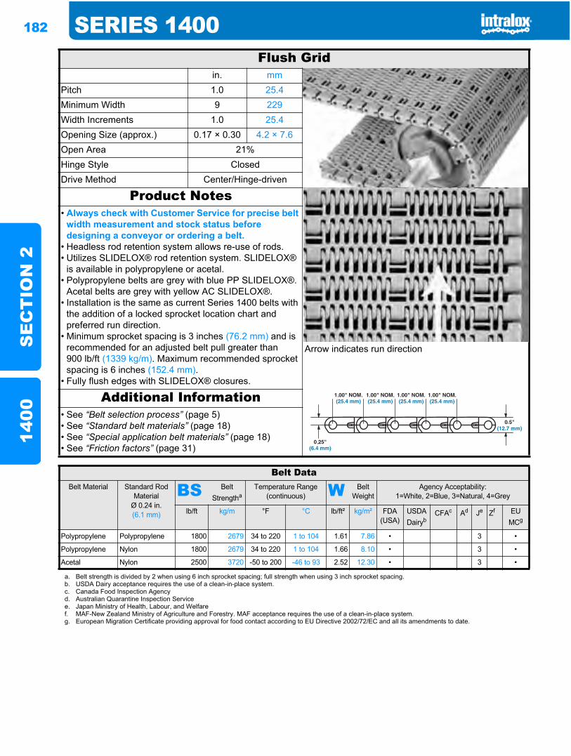
182 SERIES 1400S
EC
TIO
N 2
1400
Flush Gridin. mm
Pitch 1.0 25.4Minimum Width 9 229Width Increments 1.0 25.4Opening Size (approx.) 0.17 × 0.30 4.2 × 7.6Open Area 21%Hinge Style ClosedDrive Method Center/Hinge-driven
Product Notes
Arrow indicates run direction
• Always check with Customer Service for precise belt width measurement and stock status before designing a conveyor or ordering a belt.
• Headless rod retention system allows re-use of rods. • Utilizes SLIDELOX® rod retention system. SLIDELOX®
is available in polypropylene or acetal.• Polypropylene belts are grey with blue PP SLIDELOX®.
Acetal belts are grey with yellow AC SLIDELOX®.• Installation is the same as current Series 1400 belts with
the addition of a locked sprocket location chart and preferred run direction.
• Minimum sprocket spacing is 3 inches (76.2 mm) and is recommended for an adjusted belt pull greater than 900 lb/ft (1339 kg/m). Maximum recommended sprocket spacing is 6 inches (152.4 mm).
• Fully flush edges with SLIDELOX® closures.
Additional Information• See “Belt selection process” (page 5)• See “Standard belt materials” (page 18)• See “Special application belt materials” (page 18)• See “Friction factors” (page 31)
Belt DataBelt Material Standard Rod
MaterialØ 0.24 in. (6.1 mm)
BS Belt Strengtha
Temperature Range (continuous) W Belt
WeightAgency Acceptability:
1=White, 2=Blue, 3=Natural, 4=Grey
lb/ft kg/m °F °C lb/ft² kg/m² FDA (USA)
USDADairyb
CFAc Ad Je Zf EUMCg
Polypropylene Polypropylene 1800 2679 34 to 220 1 to 104 1.61 7.86 • 3 •
Polypropylene Nylon 1800 2679 34 to 220 1 to 104 1.66 8.10 • 3 •
Acetal Nylon 2500 3720 -50 to 200 -46 to 93 2.52 12.30 • 3 •
a. Belt strength is divided by 2 when using 6 inch sprocket spacing; full strength when using 3 inch sprocket spacing.b. USDA Dairy acceptance requires the use of a clean-in-place system.c. Canada Food Inspection Agencyd. Australian Quarantine Inspection Servicee. Japan Ministry of Health, Labour, and Welfaref. MAF-New Zealand Ministry of Agriculture and Forestry. MAF acceptance requires the use of a clean-in-place system.g. European Migration Certificate providing approval for food contact according to EU Directive 2002/72/EC and all its amendments to date.
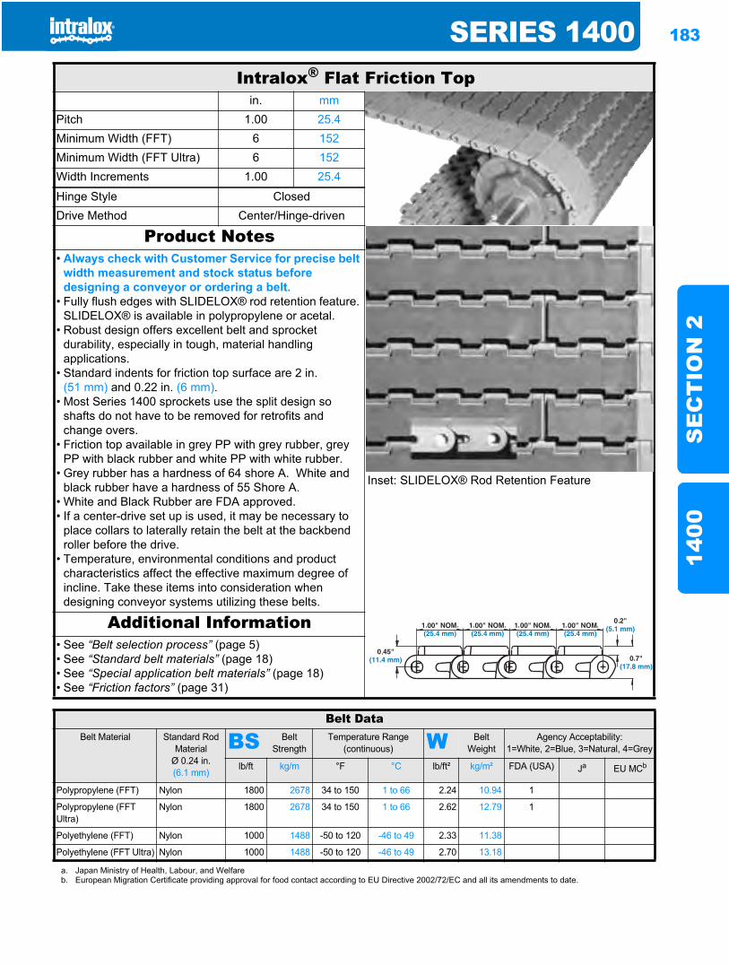
SERIES 1400 183
SE
CT
ION
214
00
Intralox® Flat Friction Topin. mm
Pitch 1.00 25.4Minimum Width (FFT) 6 152Minimum Width (FFT Ultra) 6 152Width Increments 1.00 25.4
Hinge Style ClosedDrive Method Center/Hinge-driven
Product Notes
Inset: SLIDELOX® Rod Retention Feature
• Always check with Customer Service for precise belt width measurement and stock status before designing a conveyor or ordering a belt.
• Fully flush edges with SLIDELOX® rod retention feature. SLIDELOX® is available in polypropylene or acetal.
• Robust design offers excellent belt and sprocket durability, especially in tough, material handling applications.
• Standard indents for friction top surface are 2 in. (51 mm) and 0.22 in. (6 mm).
• Most Series 1400 sprockets use the split design so shafts do not have to be removed for retrofits and change overs.
• Friction top available in grey PP with grey rubber, grey PP with black rubber and white PP with white rubber.
• Grey rubber has a hardness of 64 shore A. White and black rubber have a hardness of 55 Shore A.
• White and Black Rubber are FDA approved.• If a center-drive set up is used, it may be necessary to
place collars to laterally retain the belt at the backbend roller before the drive.
• Temperature, environmental conditions and product characteristics affect the effective maximum degree of incline. Take these items into consideration when designing conveyor systems utilizing these belts.
Additional Information• See “Belt selection process” (page 5)• See “Standard belt materials” (page 18)• See “Special application belt materials” (page 18)• See “Friction factors” (page 31)
Belt DataBelt Material Standard Rod
MaterialØ 0.24 in. (6.1 mm)
BS Belt Strength
Temperature Range (continuous) W Belt
WeightAgency Acceptability:
1=White, 2=Blue, 3=Natural, 4=Grey
lb/ft kg/m °F °C lb/ft² kg/m² FDA (USA) Ja EU MCb
Polypropylene (FFT) Nylon 1800 2678 34 to 150 1 to 66 2.24 10.94 1
Polypropylene (FFT Ultra)
Nylon 1800 2678 34 to 150 1 to 66 2.62 12.79 1
Polyethylene (FFT) Nylon 1000 1488 -50 to 120 -46 to 49 2.33 11.38
Polyethylene (FFT Ultra) Nylon 1000 1488 -50 to 120 -46 to 49 2.70 13.18
a. Japan Ministry of Health, Labour, and Welfareb. European Migration Certificate providing approval for food contact according to EU Directive 2002/72/EC and all its amendments to date.
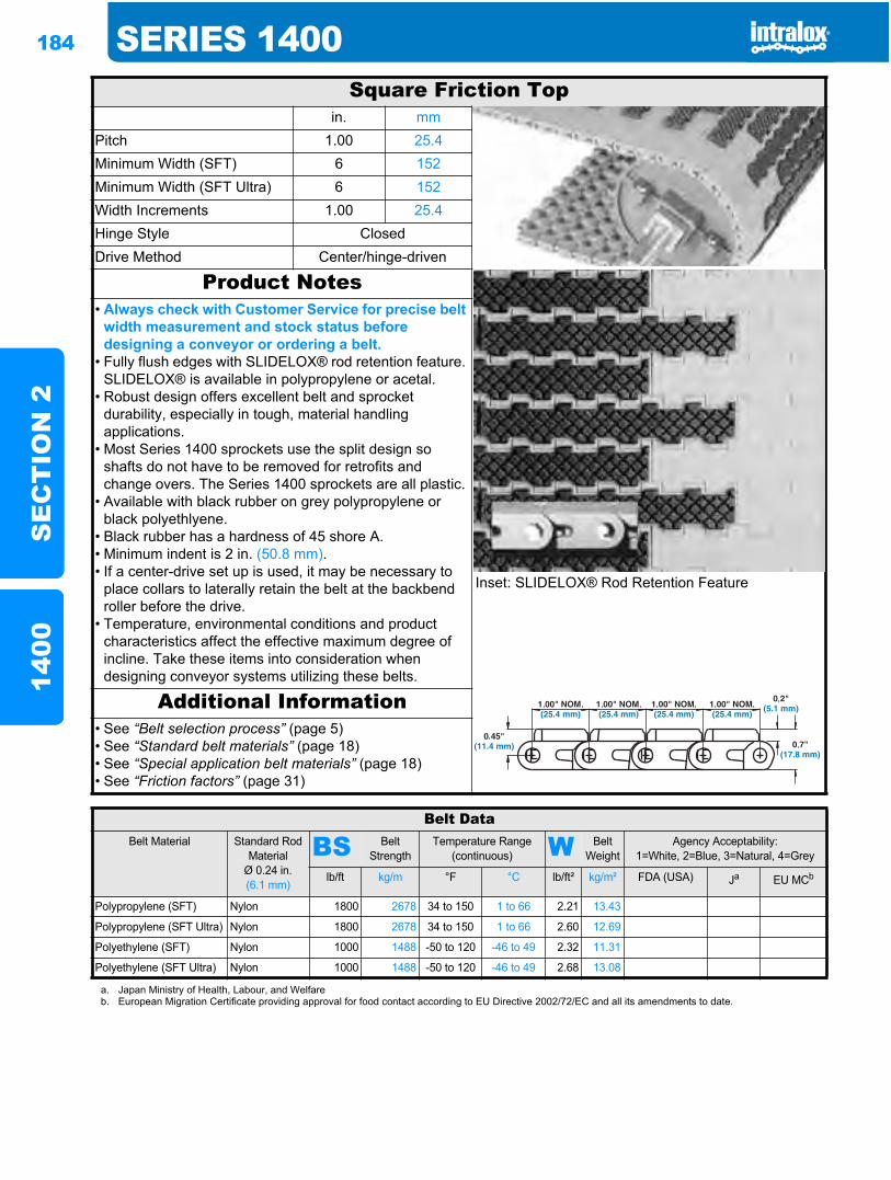
184 SERIES 1400S
EC
TIO
N 2
1400
Square Friction Topin. mm
Pitch 1.00 25.4Minimum Width (SFT) 6 152Minimum Width (SFT Ultra) 6 152Width Increments 1.00 25.4Hinge Style ClosedDrive Method Center/hinge-driven
Product Notes
Inset: SLIDELOX® Rod Retention Feature
• Always check with Customer Service for precise belt width measurement and stock status before designing a conveyor or ordering a belt.
• Fully flush edges with SLIDELOX® rod retention feature. SLIDELOX® is available in polypropylene or acetal.
• Robust design offers excellent belt and sprocket durability, especially in tough, material handling applications.
• Most Series 1400 sprockets use the split design so shafts do not have to be removed for retrofits and change overs. The Series 1400 sprockets are all plastic.
• Available with black rubber on grey polypropylene or black polyethlyene.
• Black rubber has a hardness of 45 shore A.• Minimum indent is 2 in. (50.8 mm).• If a center-drive set up is used, it may be necessary to
place collars to laterally retain the belt at the backbend roller before the drive.
• Temperature, environmental conditions and product characteristics affect the effective maximum degree of incline. Take these items into consideration when designing conveyor systems utilizing these belts.
Additional Information• See “Belt selection process” (page 5)• See “Standard belt materials” (page 18)• See “Special application belt materials” (page 18)• See “Friction factors” (page 31)
Belt DataBelt Material Standard Rod
MaterialØ 0.24 in. (6.1 mm)
BS Belt Strength
Temperature Range (continuous) W Belt
WeightAgency Acceptability:
1=White, 2=Blue, 3=Natural, 4=Grey
lb/ft kg/m °F °C lb/ft² kg/m² FDA (USA) Ja EU MCb
Polypropylene (SFT) Nylon 1800 2678 34 to 150 1 to 66 2.21 13.43
Polypropylene (SFT Ultra) Nylon 1800 2678 34 to 150 1 to 66 2.60 12.69
Polyethylene (SFT) Nylon 1000 1488 -50 to 120 -46 to 49 2.32 11.31
Polyethylene (SFT Ultra) Nylon 1000 1488 -50 to 120 -46 to 49 2.68 13.08
a. Japan Ministry of Health, Labour, and Welfareb. European Migration Certificate providing approval for food contact according to EU Directive 2002/72/EC and all its amendments to date.
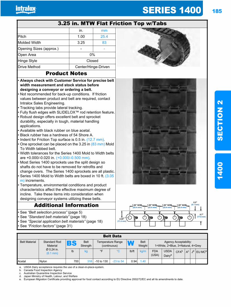
SERIES 1400 185
SE
CT
ION
214
00
3.25 in. MTW Flat Friction Top w/Tabsin. mm
Pitch 1.00 25.4Molded Width 3.25 83Opening Sizes (approx.) - -Open Area 0%Hinge Style ClosedDrive Method Center/Hinge-Driven
Product Notes• Always check with Customer Service for precise belt
width measurement and stock status before designing a conveyor or ordering a belt.
• Not recommended for back-up conditions. If friction values between product and belt are required, contact Intralox Sales Engineering.
• Tracking tabs provide lateral tracking.• Fully flush edges with SLIDELOX™ rod retention feature.• Robust design offers excellent belt and sprocket
durability, especially in tough, material handling applications.
• Available with black rubber on blue acetal.• Black rubber has a hardness of 54 Shore A.• Indent for Friction Top surface is 0.5 in. (12.7 mm).• One sprocket can be placed on the 3.25 in (83 mm) Mold
To Width tabbed belt.• Width tolerances for the Series 1400 Mold to Width belts
are +0.000/-0.020 in. (+0.000/-0.500 mm).• Most Series 1400 sprockets use the split design so
shafts do not have to be removed for retrofits and change overs. The Series 1400 sprockets are all plastic.
• Series 1400 Mold to Width belts are boxed in 10 ft. (3.05 m) increments.
• Temperature, environmental conditions and product characteristics affect the effective maximum degree of incline. Take these items into consideration when designing conveyor systems utilizing these belts.
Additional Information• See “Belt selection process” (page 5)• See “Standard belt materials” (page 18)• See “Special application belt materials” (page 18)• See “Friction factors” (page 31)
Belt DataBelt Material Standard Rod
MaterialØ 0.24 in. (6.1 mm)
BS Belt Strength
Temperature Range (continuous) W Belt
WeightAgency Acceptability:
1=White, 2=Blue, 3=Natural, 4=Grey
lb kg °F °C lb/ft kg/m FDA (USA)
USDADairya
CFAb Ac Jd EU MCe
Acetal Nylon 700 318 -10 to 130 -23 to 54 0.94 1.40
a. USDA Dairy acceptance requires the use of a clean-in-place-system.b. Canada Food Inspection Agencyc. Australian Quarantine Inspection Serviced. Japan Ministry of Health, Labour, and Welfaree. European Migration Certificate providing approval for food contact according to EU Directive 2002/72/EC and all its amendments to date.
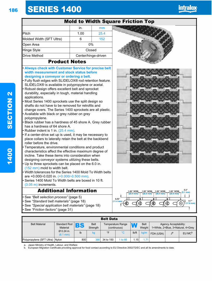
186 SERIES 1400S
EC
TIO
N 2
1400
Mold to Width Square Friction Topin. mm
Pitch 1.00 25.4Molded Width (SFT Ultra) 6 152Open Area 0%Hinge Style ClosedDrive Method Center/hinge-driven
Product Notes• Always check with Customer Service for precise belt
width measurement and stock status before designing a conveyor or ordering a belt.
• Fully flush edges with SLIDELOX® rod retention feature. SLIDELOX® is available in polypropylene or acetal.
• Robust design offers excellent belt and sprocket durability, especially in tough, material handling applications.
• Most Series 1400 sprockets use the split design so shafts do not have to be removed for retrofits and change overs. The Series 1400 sprockets are all plastic.
• Available with black or grey rubber on grey polypropylene.
• Black rubber has a hardness of 45 shore A. Grey rubber has a hardness of 64 shore A.
• Rubber indent is 1 in. (25.4 mm).• If a center-drive set up is used, it may be necessary to
place collars to laterally retain the belt at the backbend roller before the drive.
• Temperature, environmental conditions and product characteristics affect the effective maximum degree of incline. Take these items into consideration when designing conveyor systems utilizing these belts.
• Up to three sprockets can be placed on the 6.0 in. (152 mm) mold to width belt.
• Width tolerances for the Series 1400 Mold To Width belts are +0.000/-0.020 in. (+0.000/-0.500 mm).
• Series 1400 Mold To Width belts are boxed in 10 ft. (3.05 m) increments.
Additional Information• See “Belt selection process” (page 5)• See “Standard belt materials” (page 18)• See “Special application belt materials” (page 18)• See “Friction factors” (page 31)
Belt DataBelt Material Standard Rod
MaterialØ 0.24 in. (6.1 mm)
BS Belt Strength
Temperature Range (continuous) W Belt
WeightAgency Acceptability:
1=White, 2=Blue, 3=Natural, 4=Grey
lb kg °F °C lb/ft kg/m FDA (USA) Ja EU MCb
Polypropylene (SFT Ultra) Nylon 800 386 34 to 150 1 to 66 1.15 1.71
a. Japan Ministry of Health, Labour, and Welfareb. European Migration Certificate providing approval for food contact according to EU Directive 2002/72/EC and all its amendments to date.
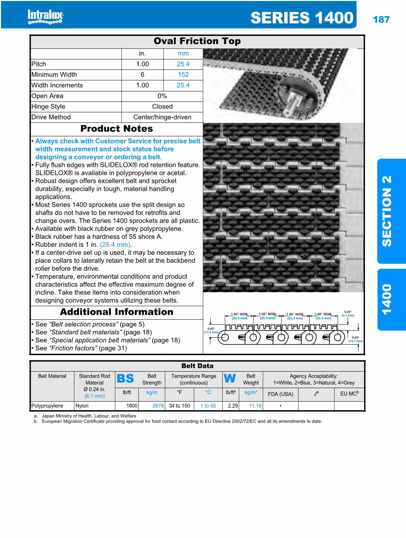
SERIES 1400 187
SE
CT
ION
214
00
Oval Friction Topin. mm
Pitch 1.00 25.4Minimum Width 6 152Width Increments 1.00 25.4Open Area 0%Hinge Style ClosedDrive Method Center/hinge-driven
Product Notes• Always check with Customer Service for precise belt
width measurement and stock status before designing a conveyor or ordering a belt.
• Fully flush edges with SLIDELOX® rod retention feature. SLIDELOX® is available in polypropylene or acetal.
• Robust design offers excellent belt and sprocket durability, especially in tough, material handling applications.
• Most Series 1400 sprockets use the split design so shafts do not have to be removed for retrofits and change overs. The Series 1400 sprockets are all plastic.
• Available with black rubber on grey polypropylene.• Black rubber has a hardness of 55 shore A.• Rubber indent is 1 in. (25.4 mm).• If a center-drive set up is used, it may be necessary to
place collars to laterally retain the belt at the backbend roller before the drive.
• Temperature, environmental conditions and product characteristics affect the effective maximum degree of incline. Take these items into consideration when designing conveyor systems utilizing these belts.
Additional Information• See “Belt selection process” (page 5)• See “Standard belt materials” (page 18)• See “Special application belt materials” (page 18)• See “Friction factors” (page 31)
Belt DataBelt Material Standard Rod
MaterialØ 0.24 in. (6.1 mm)
BS Belt Strength
Temperature Range (continuous) W Belt
WeightAgency Acceptability:
1=White, 2=Blue, 3=Natural, 4=Grey
lb/ft kg/m °F °C lb/ft² kg/m² FDA (USA) Ja EU MCb
Polypropylene Nylon 1800 2678 34 to 150 1 to 66 2.29 11.18 •
a. Japan Ministry of Health, Labour, and Welfareb. European Migration Certificate providing approval for food contact according to EU Directive 2002/72/EC and all its amendments to date.
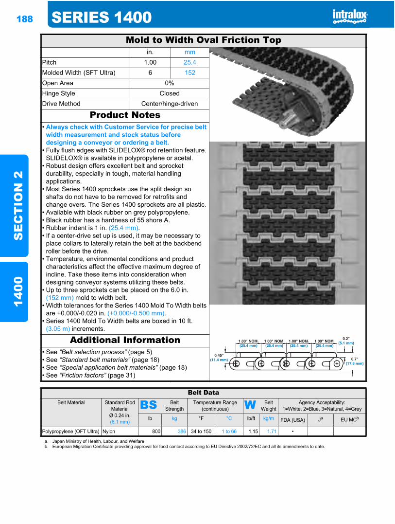
188 SERIES 1400S
EC
TIO
N 2
1400
Mold to Width Oval Friction Topin. mm
Pitch 1.00 25.4Molded Width (SFT Ultra) 6 152Open Area 0%Hinge Style ClosedDrive Method Center/hinge-driven
Product Notes• Always check with Customer Service for precise belt
width measurement and stock status before designing a conveyor or ordering a belt.
• Fully flush edges with SLIDELOX® rod retention feature. SLIDELOX® is available in polypropylene or acetal.
• Robust design offers excellent belt and sprocket durability, especially in tough, material handling applications.
• Most Series 1400 sprockets use the split design so shafts do not have to be removed for retrofits and change overs. The Series 1400 sprockets are all plastic.
• Available with black rubber on grey polypropylene.• Black rubber has a hardness of 55 shore A.• Rubber indent is 1 in. (25.4 mm).• If a center-drive set up is used, it may be necessary to
place collars to laterally retain the belt at the backbend roller before the drive.
• Temperature, environmental conditions and product characteristics affect the effective maximum degree of incline. Take these items into consideration when designing conveyor systems utilizing these belts.
• Up to three sprockets can be placed on the 6.0 in. (152 mm) mold to width belt.
• Width tolerances for the Series 1400 Mold To Width belts are +0.000/-0.020 in. (+0.000/-0.500 mm).
• Series 1400 Mold To Width belts are boxed in 10 ft. (3.05 m) increments.
Additional Information• See “Belt selection process” (page 5)• See “Standard belt materials” (page 18)• See “Special application belt materials” (page 18)• See “Friction factors” (page 31)
Belt DataBelt Material Standard Rod
MaterialØ 0.24 in. (6.1 mm)
BS Belt Strength
Temperature Range (continuous) W Belt
WeightAgency Acceptability:
1=White, 2=Blue, 3=Natural, 4=Grey
lb kg °F °C lb/ft kg/m FDA (USA) Ja EU MCb
Polypropylene (OFT Ultra) Nylon 800 386 34 to 150 1 to 66 1.15 1.71 •
a. Japan Ministry of Health, Labour, and Welfareb. European Migration Certificate providing approval for food contact according to EU Directive 2002/72/EC and all its amendments to date.
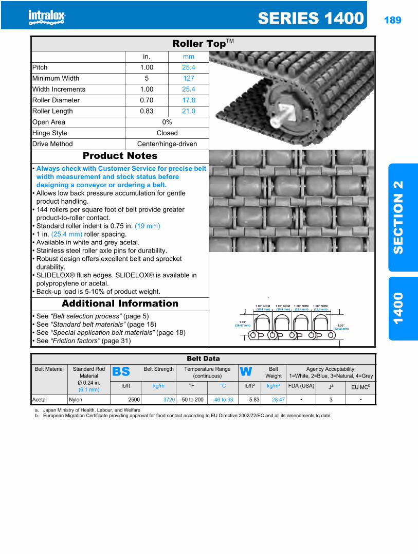
SERIES 1400 189
SE
CT
ION
214
00
Roller TopTM
in. mmPitch 1.00 25.4Minimum Width 5 127Width Increments 1.00 25.4Roller Diameter 0.70 17.8Roller Length 0.83 21.0Open Area 0%Hinge Style ClosedDrive Method Center/hinge-driven
Product Notes• Always check with Customer Service for precise belt
width measurement and stock status before designing a conveyor or ordering a belt.
• Allows low back pressure accumulation for gentle product handling.
• 144 rollers per square foot of belt provide greater product-to-roller contact.
• Standard roller indent is 0.75 in. (19 mm)• 1 in. (25.4 mm) roller spacing.• Available in white and grey acetal.• Stainless steel roller axle pins for durability.• Robust design offers excellent belt and sprocket
durability.• SLIDELOX® flush edges. SLIDELOX® is available in
polypropylene or acetal.• Back-up load is 5-10% of product weight.
Additional Information• See “Belt selection process” (page 5)• See “Standard belt materials” (page 18)• See “Special application belt materials” (page 18)• See “Friction factors” (page 31)
Belt DataBelt Material Standard Rod
MaterialØ 0.24 in. (6.1 mm)
BS Belt Strength Temperature Range (continuous) W Belt
WeightAgency Acceptability:
1=White, 2=Blue, 3=Natural, 4=Grey
lb/ft kg/m °F °C lb/ft² kg/m² FDA (USA) Ja EU MCb
Acetal Nylon 2500 3720 -50 to 200 -46 to 93 5.83 28.47 • 3 •
a. Japan Ministry of Health, Labour, and Welfareb. European Migration Certificate providing approval for food contact according to EU Directive 2002/72/EC and all its amendments to date.
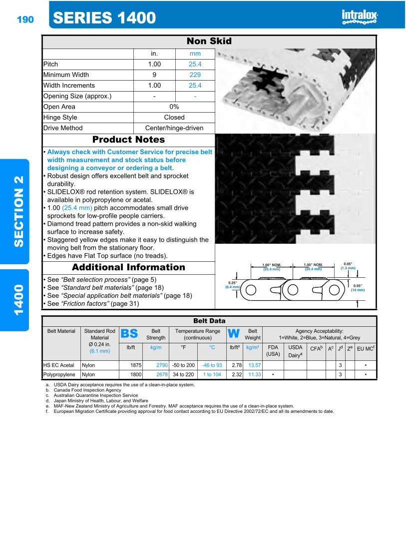
190 SERIES 1400S
EC
TIO
N 2
1400
Non Skidin. mm
Pitch 1.00 25.4Minimum Width 9 229Width Increments 1.00 25.4Opening Size (approx.) - -Open Area 0%Hinge Style ClosedDrive Method Center/hinge-driven
Product Notes• Always check with Customer Service for precise belt
width measurement and stock status before designing a conveyor or ordering a belt.
• Robust design offers excellent belt and sprocket durability.
• SLIDELOX® rod retention system. SLIDELOX® is available in polypropylene or acetal.
• 1.00 (25.4 mm) pitch accommodates small drive sprockets for low-profile people carriers.
• Diamond tread pattern provides a non-skid walking surface to increase safety.
• Staggered yellow edges make it easy to distinguish the moving belt from the stationary floor.
• Edges have Flat Top surface (no treads).
Additional Information• See “Belt selection process” (page 5)• See “Standard belt materials” (page 18)• See “Special application belt materials” (page 18)• See “Friction factors” (page 31)
Belt DataBelt Material Standard Rod
MaterialØ 0.24 in. (6.1 mm)
BS Belt Strength
Temperature Range (continuous) W Belt
WeightAgency Acceptability:
1=White, 2=Blue, 3=Natural, 4=Grey
lb/ft kg/m °F °C lb/ft² kg/m² FDA (USA)
USDADairya
CFAb Ac Jd Ze EU MCf
HS EC Acetal Nylon 1875 2790 -50 to 200 -46 to 93 2.78 13.57 3 •
Polypropylene Nylon 1800 2678 34 to 220 1 to 104 2.32 11.33 • 3 •
a. USDA Dairy acceptance requires the use of a clean-in-place system.b. Canada Food Inspection Agencyc. Australian Quarantine Inspection Serviced. Japan Ministry of Health, Labour, and Welfaree. MAF-New Zealand Ministry of Agriculture and Forestry. MAF acceptance requires the use of a clean-in-place system.f. European Migration Certificate providing approval for food contact according to EU Directive 2002/72/EC and all its amendments to date.
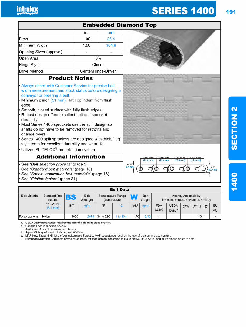
SERIES 1400 191
SE
CT
ION
214
00
Embedded Diamond Topin. mm
Pitch 1.00 25.4MInimum Width 12.0 304.8Opening Sizes (approx.) - -Open Area 0%Hinge Style ClosedDrive Method Center/Hinge-Driven
Product Notes• Always check with Customer Service for precise belt
width measurement and stock status before designing a conveyor or ordering a belt.
• Minimum 2 inch (51 mm) Flat Top indent from flush edge.
• Smooth, closed surface with fully flush edges.• Robust design offers excellent belt and sprocket
durability.• Most Series 1400 sprockets use the split design so
shafts do not have to be removed for retrofits and change overs.
• Series 1400 split sprockets are designed with thick, “lug” style teeth for excellent durability and wear life.
• Utilizes SLIDELOX® rod retention system.
Additional Information• See “Belt selection process” (page 5)• See “Standard belt materials” (page 18)• See “Special application belt materials” (page 18)• See “Friction factors” (page 31)
Belt DataBelt Material Standard Rod
MaterialØ 0.24 in. (6.1 mm)
BS Belt Strength
Temperature Range (continuous) W Belt
WeightAgency Acceptability
1=White, 2=Blue, 3=Natural, 4=Grey
lb/ft kg/m °F °C lb/ft² kg/m² FDA(USA)
USDADairya
CFAb Ac Jd Ze EUMCf
Polypropylene Nylon 1800 2678 34 to 220 1 to 104 1.70 8.30 • 3 •
a. USDA Dairy acceptance requires the use of a clean-in-place system.b. Canada Food Inspection Agencyc. Australian Quarantine Inspection Serviced. Japan Ministry of Health, Labour, and Welfaree. MAF-New Zealand Ministry of Agriculture and Forestry. MAF acceptance requires the use of a clean-in-place system.f. European Migration Certificate providing approval for food contact according to EU Directive 2002/72/EC and all its amendments to date.
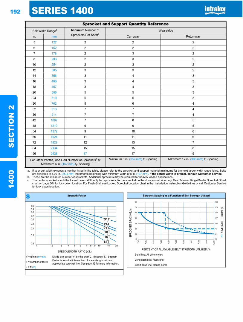
192 SERIES 1400S
EC
TIO
N 2
1400
Sprocket and Support Quantity ReferenceBelt Width Rangea Minimum Number of
Sprockets Per ShaftbWearstrips
in. mm Carryway Returnway
5 127 2 2 2
6 152 2 2 2
7 178 2 3 2
8 203 2 3 2
10 254 2 3 2
12 305 3 3 2
14 356 3 4 3
16 406 3 4 3
18 457 3 4 3
20 508 5 5 3
24 610 5 5 3
30 762 5 6 4
32 813 7 7 4
36 914 7 7 4
42 1067 7 8 5
48 1219 9 9 5
54 1372 9 10 6
60 1524 11 11 6
72 1829 12 13 7
84 2134 15 15 8
96 2438 17 17 9
For Other Widths, Use Odd Number of Sprocketsc at Maximum 6 in. (152 mm) CL Spacing
Maximum 6 in. (152 mm) CL Spacing Maximum 12 in. (305 mm) CL Spacing
a. If your belt width exceeds a number listed in the table, please refer to the sprocket and support material minimums for the next larger width range listed. Beltsare available in 1.00 in. (25.4 mm) increments beginning with minimum width of 5 in. (127 mm). If the actual width is critical, consult Customer Service.
b. These are the minimum number of sprockets. Additional sprockets may be required for heavily loaded applications.c. The center sprocket should be locked down. With only two sprockets, fix the sprocket on the drive journal side only. See Retainer Rings/Center Sprocket Offset
chart on page 304 for lock down location. For Flush Grid, see Locked Sprocket Location chart in the Installation Instruction Guidelines or call Customer Servicefor lock down location.
S Strength Factor
SPEED/LENGTH RATIO (V/L)
V = ft/min (m/min) Divide belt speed “V” by the shaft CL distance “L”. Strength Factor is found at intersection of speed/length ratio and appropriate sprocket line. See page 36 for more information.T = number of teeth
L = ft (m)
1.00.90.8
0.70.6
0.5
0.4
0.3
0.21 2 3 4 5 6 7 8 9 10 15 20
Sprocket Spacing as a Function of Belt Strength Utilized
SPRO
CKET
SPA
CING
, in.
SPROCKET SPACING
, mm
PERCENT OF ALLOWABLE BELT STRENGTH UTILIZED, %
Solid line: All other styles
Long dash line: Flush grid
Short dash line: Round bores
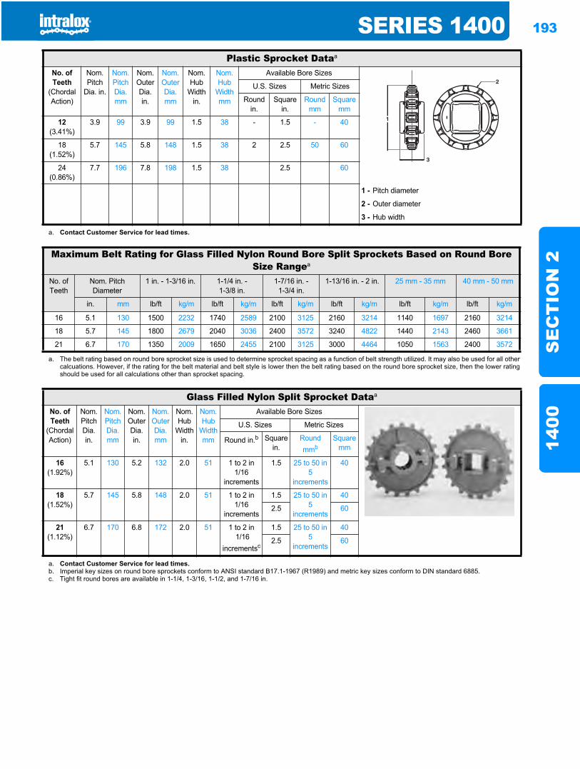
SERIES 1400 193
SE
CT
ION
214
00
Plastic Sprocket Dataa
No. of Teeth
(Chordal Action)
Nom. Pitch
Dia. in.
Nom. Pitch Dia. mm
Nom. OuterDia. in.
Nom. Outer Dia. mm
Nom. Hub
Width in.
Nom. Hub
Width mm
Available Bore Sizes
U.S. Sizes Metric Sizes
Round in.
Square in.
Round mm
Square mm
12(3.41%)
3.9 99 3.9 99 1.5 38 - 1.5 - 40
18(1.52%)
5.7 145 5.8 148 1.5 38 2 2.5 50 60
24(0.86%)
7.7 196 7.8 198 1.5 38 2.5 60
1 - Pitch diameter
2 - Outer diameter
3 - Hub width
a. Contact Customer Service for lead times.
Maximum Belt Rating for Glass Filled Nylon Round Bore Split Sprockets Based on Round Bore Size Rangea
No. ofTeeth
Nom. Pitch Diameter
1 in. - 1-3/16 in. 1-1/4 in. -1-3/8 in.
1-7/16 in. -1-3/4 in.
1-13/16 in. - 2 in. 25 mm - 35 mm 40 mm - 50 mm
in. mm lb/ft kg/m lb/ft kg/m lb/ft kg/m lb/ft kg/m lb/ft kg/m lb/ft kg/m
16 5.1 130 1500 2232 1740 2589 2100 3125 2160 3214 1140 1697 2160 3214
18 5.7 145 1800 2679 2040 3036 2400 3572 3240 4822 1440 2143 2460 3661
21 6.7 170 1350 2009 1650 2455 2100 3125 3000 4464 1050 1563 2400 3572
a. The belt rating based on round bore sprocket size is used to determine sprocket spacing as a function of belt strength utilized. It may also be used for all othercalcuations. However, if the rating for the belt material and belt style is lower then the belt rating based on the round bore sprocket size, then the lower ratingshould be used for all calculations other than sprocket spacing.
Glass Filled Nylon Split Sprocket Dataa
No. of Teeth
(Chordal Action)
Nom. Pitch Dia. in.
Nom. Pitch Dia. mm
Nom. Outer Dia. in.
Nom. Outer Dia.mm
Nom. Hub
Width in.
Nom. Hub
Width mm
Available Bore Sizes
U.S. Sizes Metric Sizes
Round in.b Square in.
Round mmb
Square mm
16(1.92%)
5.1 130 5.2 132 2.0 51 1 to 2 in1/16
increments
1.5 25 to 50 in5
increments
40
18(1.52%)
5.7 145 5.8 148 2.0 51 1 to 2 in1/16
increments
1.5 25 to 50 in5
increments
40
2.5 60
21(1.12%)
6.7 170 6.8 172 2.0 51 1 to 2 in 1/16
incrementsc
1.5 25 to 50 in5
increments
40
2.5 60
a. Contact Customer Service for lead times.b. Imperial key sizes on round bore sprockets conform to ANSI standard B17.1-1967 (R1989) and metric key sizes conform to DIN standard 6885.c. Tight fit round bores are available in 1-1/4, 1-3/16, 1-1/2, and 1-7/16 in.
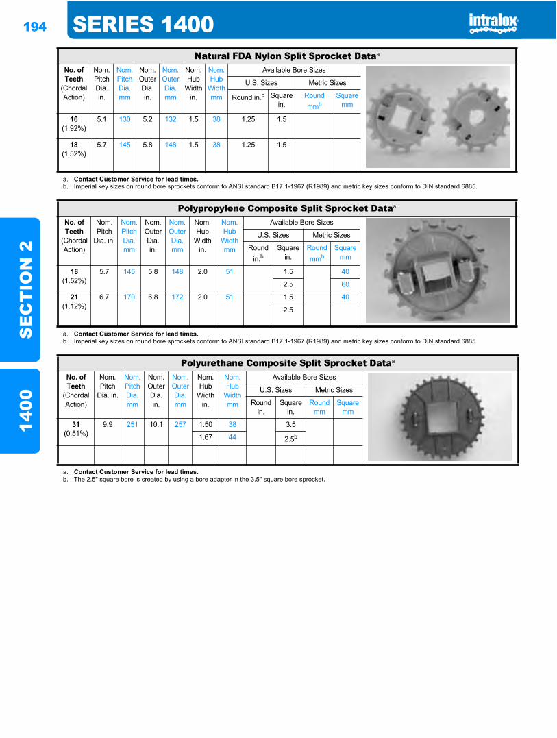
194 SERIES 1400S
EC
TIO
N 2
1400
Natural FDA Nylon Split Sprocket Dataa
No. of Teeth
(Chordal Action)
Nom. Pitch Dia. in.
Nom. Pitch Dia.mm
Nom. Outer Dia.in.
Nom. Outer Dia.mm
Nom. Hub
Width in.
Nom. Hub
Width mm
Available Bore Sizes
U.S. Sizes Metric Sizes
Round in.b Square in.
Round mmb
Square mm
16(1.92%)
5.1 130 5.2 132 1.5 38 1.25 1.5
18(1.52%)
5.7 145 5.8 148 1.5 38 1.25 1.5
a. Contact Customer Service for lead times.b. Imperial key sizes on round bore sprockets conform to ANSI standard B17.1-1967 (R1989) and metric key sizes conform to DIN standard 6885.
Polypropylene Composite Split Sprocket Dataa
No. of Teeth
(Chordal Action)
Nom. Pitch
Dia. in.
Nom. Pitch Dia. mm
Nom. Outer Dia.in.
Nom. Outer Dia.mm
Nom. Hub
Width in.
Nom. Hub
Width mm
Available Bore Sizes
U.S. Sizes Metric Sizes
Round in.b
Square in.
Round mmb
Square mm
18(1.52%)
5.7 145 5.8 148 2.0 51 1.5 40
2.5 60
21(1.12%)
6.7 170 6.8 172 2.0 51 1.5 40
2.5
a. Contact Customer Service for lead times.b. Imperial key sizes on round bore sprockets conform to ANSI standard B17.1-1967 (R1989) and metric key sizes conform to DIN standard 6885.
Polyurethane Composite Split Sprocket Dataa
No. of Teeth
(Chordal Action)
Nom. Pitch
Dia. in.
Nom. Pitch Dia. mm
Nom. Outer Dia.in.
Nom. Outer Dia.mm
Nom. Hub
Width in.
Nom. Hub
Width mm
Available Bore Sizes
U.S. Sizes Metric Sizes
Round in.
Square in.
Round mm
Square mm
31(0.51%)
9.9 251 10.1 257 1.50 38 3.5
1.67 44 2.5b
a. Contact Customer Service for lead times.b. The 2.5" square bore is created by using a bore adapter in the 3.5" square bore sprocket.
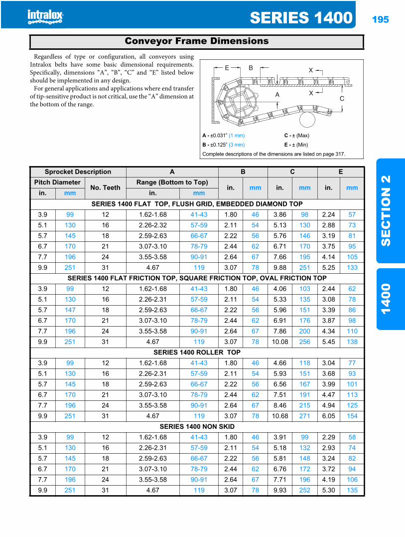
SERIES 1400 195
SE
CT
ION
214
00
Regardless of type or configuration, all conveyors usingIntralox belts have some basic dimensional requirements.Specifically, dimensions “A”, “B”, “C” and “E” listed belowshould be implemented in any design.
For general applications and applications where end transferof tip-sensitive product is not critical, use the “A” dimension atthe bottom of the range.
Conveyor Frame Dimensions
A - ±0.031” (1 mm) C - ± (Max)
B - ±0.125” (3 mm) E - ± (Min)
Complete descriptions of the dimensions are listed on page 317.
Sprocket Description A B C EPitch Diameter
No. TeethRange (Bottom to Top)
in. mm in. mm in. mmin. mm in. mm
SERIES 1400 FLAT TOP, FLUSH GRID, EMBEDDED DIAMOND TOP3.9 99 12 1.62-1.68 41-43 1.80 46 3.86 98 2.24 575.1 130 16 2.26-2.32 57-59 2.11 54 5.13 130 2.88 735.7 145 18 2.59-2.63 66-67 2.22 56 5.76 146 3.19 816.7 170 21 3.07-3.10 78-79 2.44 62 6.71 170 3.75 957.7 196 24 3.55-3.58 90-91 2.64 67 7.66 195 4.14 1059.9 251 31 4.67 119 3.07 78 9.88 251 5.25 133
SERIES 1400 FLAT FRICTION TOP, SQUARE FRICTION TOP, OVAL FRICTION TOP3.9 99 12 1.62-1.68 41-43 1.80 46 4.06 103 2.44 625.1 130 16 2.26-2.31 57-59 2.11 54 5.33 135 3.08 785.7 147 18 2.59-2.63 66-67 2.22 56 5.96 151 3.39 866.7 170 21 3.07-3.10 78-79 2.44 62 6.91 176 3.87 987.7 196 24 3.55-3.58 90-91 2.64 67 7.86 200 4.34 1109.9 251 31 4.67 119 3.07 78 10.08 256 5.45 138
SERIES 1400 ROLLER TOP3.9 99 12 1.62-1.68 41-43 1.80 46 4.66 118 3.04 775.1 130 16 2.26-2.31 57-59 2.11 54 5.93 151 3.68 935.7 145 18 2.59-2.63 66-67 2.22 56 6.56 167 3.99 1016.7 170 21 3.07-3.10 78-79 2.44 62 7.51 191 4.47 1137.7 196 24 3.55-3.58 90-91 2.64 67 8.46 215 4.94 1259.9 251 31 4.67 119 3.07 78 10.68 271 6.05 154
SERIES 1400 NON SKID3.9 99 12 1.62-1.68 41-43 1.80 46 3.91 99 2.29 585.1 130 16 2.26-2.31 57-59 2.11 54 5.18 132 2.93 745.7 145 18 2.59-2.63 66-67 2.22 56 5.81 148 3.24 826.7 170 21 3.07-3.10 78-79 2.44 62 6.76 172 3.72 947.7 196 24 3.55-3.58 90-91 2.64 67 7.71 196 4.19 1069.9 251 31 4.67 119 3.07 78 9.93 252 5.30 135

196 SERIES 1400S
EC
TIO
N 2
1400
Where there is a transfer point from a belt without fingertransfer plates to a dead plate, there should be a gap betweenthe surfaces to allow for the chordal action of the belt. As thebelt engages its sprockets, chordal action causes the modules tomove past a fixed point (the tip of the dead plate) with varyingclearances. The table below shows the minimum amount ofgap which occurs at the “low point” of the modules if the tip ofthe dead plate just comes in contact with the “high point” asthe modules pass.
In some installations it may be desirable to keep the tip of thedead plate in contact with the belt, rather than allow a gap tooccur. This can be done by hinging the mounting bracket forthe dead plate. This allows the dead plate to move as themodules pass, but results in a small oscillating motion whichmay present tippage problems for sensitive containers orproducts.
Dead Plate Gap
1 - Top surface of dead plate 2 - Dead plate gap
Note: The top surface of the dead plate is typically 0.031 in. (0.8 mm)above the belt surface for product transfer onto the belt, and 0.031 in. (0.8 mm) below the belt surface for product transfer off the belt.
21
Sprocket Description GapPitch Diameter
No. Teeth in. mmin. mm3.9 99 12 0.066 1.75.1 130 16 0.050 1.35.7 145 18 0.044 1.16.7 170 21 0.038 1.07.7 196 24 0.033 0.89.9 251 31 0.025 0.6
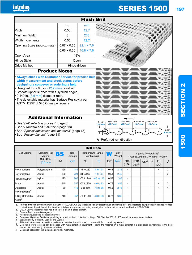
SERIES 1500 197
SE
CT
ION
215
00
Series 15001500
Flush Gridin. mm
Pitch 0.50 12.7Minimum Width 8 203Width Increments 0.50 12.7Opening Sizes (approximate) 0.87 × 0.30 22.1 × 7.6
0.66 × 0.30 16.8 × 7.6Open Area 48%Hinge Style OpenDrive Method Hinge-driven
Product Notes• Always check with Customer Service for precise belt
width measurement and stock status before designing a conveyor or ordering a belt.
• Designed for a 0.5 in. (12.7 mm) nosebar.• Smooth upper surface with fully flush edges.• 0.140 in. (3.6 mm) diameter rods.• The detectable material has Surface Resistivity per
ASTM_D257 of 545 Ohms per square.
Additional Information• See “Belt selection process” (page 5)• See “Standard belt materials” (page 18)• See “Special application belt materials” (page 18)• See “Friction factors” (page 31)
A -Preferred run direction
Belt DataBelt Material Standard Rod
MaterialØ 0.140 in. (3.6 mm)
BS Belt Strength
Temperature Range (continuous) W Belt
WeightAgency Acceptabilitya
1=White, 2=Blue, 3=Natural, 4=Grey
lb/ft kg/m °F °C lb/ft² kg/m² FDA(USA)
USDADairyb
CFAc Ad EUMCe
Jf
Polypropylene Polypropylene 125 186 34 to 220 1 to 104 0.44 2.12 • • 3
Polypropylene Acetal 150 223 34 to 200 1 to 93 0.51 2.40 • • 3
FDA HR Nylong Nylon 175 260 -50 to 240 -46 to 116 0.58 2.83 •
Acetal Acetal 240 357 -50 to 200 -46 to 93 0.73 3.56 • • 3
Detectable Polypropyleneh
Acetal 80 119 0 to 150 -18 to 66 0.56 2.73 • • 4
X-Ray Detectable Acetali
Acetal 240 357 -50 to 200 -46 to 93 0.78 3.66 •
a. Prior to Intralox’s development of the Series 1500, USDA-FSIS Meat and Poultry discontinued publishing a list of acceptable new products designed for foodcontact. As of the printing of this literature, third party approvals are being investigated, but are not yet sanctioned by the USDA-FSIS.
b. USDA Dairy acceptance requires the use of a clean-in-place-system.c. Canada Food Inspection Agencyd. Australian Quarantine Inspection Servicee. European Migration Certificate providing approval for food contact according to EU Directive 2002/72/EC and all its amendments to date.f. Japan Ministry of Health, Labour, and Welfareg. This product may not be used for food contact articles that will come in contact with food containing alcohol.h. Detectable Polypropylene can be sensed with metal detection equipment. Testing the material on a metal detector in a production environment is the best
method for determining detection sensitivity.i. Designed specifically to be detected by x-ray machines.

198 SERIES 1500S
EC
TIO
N 2
1500
Sprocket and Support Quantity ReferenceBelt Width Rangea Minimum Number of Sprockets
Per ShaftbWearstrips
in. mm Carryway Returnway
8 203 3 3 2
10 254 3 3 2
12 305 3 3 2
14 356 3 4 3
16 406 5 4 3
18 457 5 4 3
20 508 5 5 3
22 559 5 5 3
24 610 7 5 3
26 660 7 6 4
28 711 7 6 4
30 762 7 6 4
32 813 9 7 4
34 864 9 7 4
36 914 9 7 4
38 965 9 8 5
40 1016 11 8 5
42 1067 11 8 5
44 1118 11 9 5
46 1168 11 9 5
48 1219 13 9 5
50 1270 13 10 6
52 1321 13 10 6
54 1372 13 10 6
56 1422 15 11 6
58 1473 15 11 6
60 1524 15 11 6
62 1575 15 12 7
64 1626 17 12 7
For Other Widths, Use Odd Number of Sprocketsc at Maximum 6 in. (152 mm) CL Spacing
Maximum 6 in. (152 mm) CL Spacing Maximum 12 in. (305 mm) CL Spacing
a. Belts are available in 0.50 in. (12.7 mm) increments beginning with 8 in. (203 mm). If the actual width is critical, consult Customer Service.b. These are the minimum number of sprockets. Additional sprockets may be required for heavily loaded applications.c. The center sprocket should be locked down. With only two sprockets, fix the sprocket on the drive journal side only. See Locked Sprocket Location chart in the
Installation Instruction Guidelines or call Customer Service for lock down location.
S Strength Factor
SPEED/LENGTH RATIO (V/L)
V = ft/min (m/min) Divide belt speed “V” by the shaft CL distance “L”. Strength Factor is found at intersection of speed/length ratio and appropriate sprocket line. See page 36 for more information.T = number of teeth
L = ft (m)
Sprocket Spacing as a Function of Belt Strength Utilized
SPRO
CKET
SPA
CING
, in.
SPROCKET SPACING
, mm
PERCENT OF ALLOWABLE BELT STRENGTH UTILIZED, %
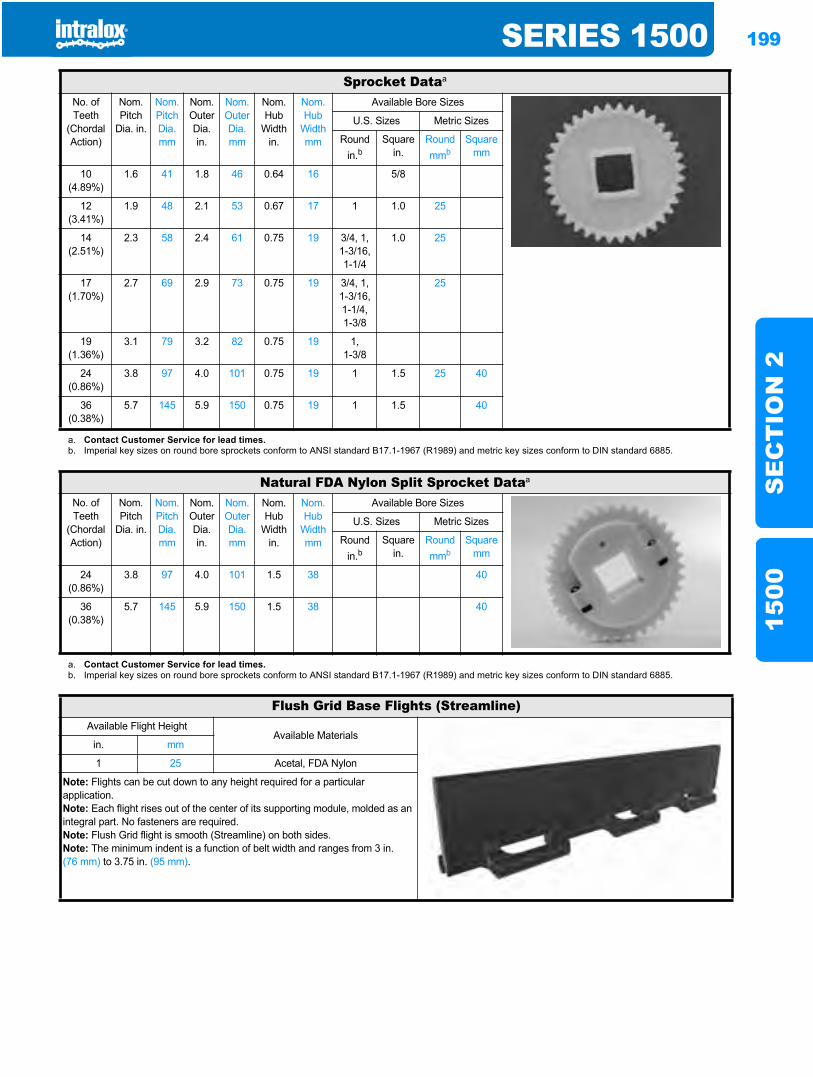
SERIES 1500 199
SE
CT
ION
215
00
Sprocket Dataa
No. of Teeth
(Chordal Action)
Nom. Pitch
Dia. in.
Nom. Pitch Dia. mm
Nom. Outer Dia. in.
Nom. Outer Dia.mm
Nom. Hub
Width in.
Nom. Hub
Width mm
Available Bore Sizes
U.S. Sizes Metric Sizes
Round in.b
Square in.
Round mmb
Square mm
10(4.89%)
1.6 41 1.8 46 0.64 16 5/8
12(3.41%)
1.9 48 2.1 53 0.67 17 1 1.0 25
14(2.51%)
2.3 58 2.4 61 0.75 19 3/4, 1, 1-3/16, 1-1/4
1.0 25
17(1.70%)
2.7 69 2.9 73 0.75 19 3/4, 1,1-3/16,1-1/4,1-3/8
25
19(1.36%)
3.1 79 3.2 82 0.75 19 1,1-3/8
24(0.86%)
3.8 97 4.0 101 0.75 19 1 1.5 25 40
36(0.38%)
5.7 145 5.9 150 0.75 19 1 1.5 40
a. Contact Customer Service for lead times.b. Imperial key sizes on round bore sprockets conform to ANSI standard B17.1-1967 (R1989) and metric key sizes conform to DIN standard 6885.
Natural FDA Nylon Split Sprocket Dataa
No. of Teeth
(Chordal Action)
Nom. Pitch
Dia. in.
Nom. Pitch Dia. mm
Nom. Outer Dia. in.
Nom. Outer Dia.mm
Nom. Hub
Width in.
Nom. Hub
Width mm
Available Bore Sizes
U.S. Sizes Metric Sizes
Round in.b
Square in.
Round mmb
Square mm
24(0.86%)
3.8 97 4.0 101 1.5 38 40
36(0.38%)
5.7 145 5.9 150 1.5 38 40
a. Contact Customer Service for lead times.b. Imperial key sizes on round bore sprockets conform to ANSI standard B17.1-1967 (R1989) and metric key sizes conform to DIN standard 6885.
Flush Grid Base Flights (Streamline)Available Flight Height
Available Materialsin. mm
1 25 Acetal, FDA Nylon
Note: Flights can be cut down to any height required for a particular application.Note: Each flight rises out of the center of its supporting module, molded as an integral part. No fasteners are required.Note: Flush Grid flight is smooth (Streamline) on both sides.Note: The minimum indent is a function of belt width and ranges from 3 in. (76 mm) to 3.75 in. (95 mm).
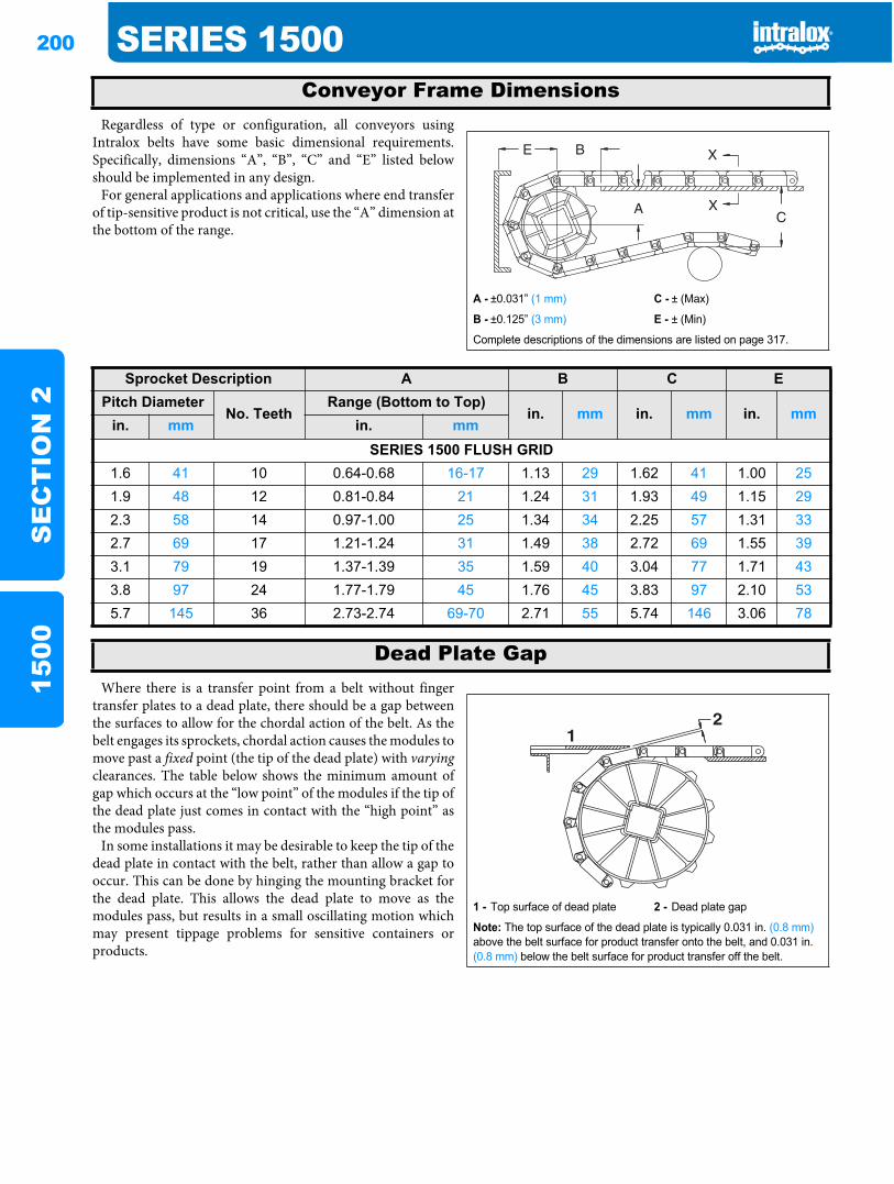
200 SERIES 1500S
EC
TIO
N 2
1500
Regardless of type or configuration, all conveyors usingIntralox belts have some basic dimensional requirements.Specifically, dimensions “A”, “B”, “C” and “E” listed belowshould be implemented in any design.
For general applications and applications where end transferof tip-sensitive product is not critical, use the “A” dimension atthe bottom of the range.
Where there is a transfer point from a belt without fingertransfer plates to a dead plate, there should be a gap betweenthe surfaces to allow for the chordal action of the belt. As thebelt engages its sprockets, chordal action causes the modules tomove past a fixed point (the tip of the dead plate) with varyingclearances. The table below shows the minimum amount ofgap which occurs at the “low point” of the modules if the tip ofthe dead plate just comes in contact with the “high point” asthe modules pass.
In some installations it may be desirable to keep the tip of thedead plate in contact with the belt, rather than allow a gap tooccur. This can be done by hinging the mounting bracket forthe dead plate. This allows the dead plate to move as themodules pass, but results in a small oscillating motion whichmay present tippage problems for sensitive containers orproducts.
Conveyor Frame Dimensions
A - ±0.031” (1 mm) C - ± (Max)
B - ±0.125” (3 mm) E - ± (Min)
Complete descriptions of the dimensions are listed on page 317.
Sprocket Description A B C EPitch Diameter
No. TeethRange (Bottom to Top)
in. mm in. mm in. mmin. mm in. mm
SERIES 1500 FLUSH GRID1.6 41 10 0.64-0.68 16-17 1.13 29 1.62 41 1.00 251.9 48 12 0.81-0.84 21 1.24 31 1.93 49 1.15 292.3 58 14 0.97-1.00 25 1.34 34 2.25 57 1.31 332.7 69 17 1.21-1.24 31 1.49 38 2.72 69 1.55 393.1 79 19 1.37-1.39 35 1.59 40 3.04 77 1.71 433.8 97 24 1.77-1.79 45 1.76 45 3.83 97 2.10 535.7 145 36 2.73-2.74 69-70 2.71 55 5.74 146 3.06 78
Dead Plate Gap
1 - Top surface of dead plate 2 - Dead plate gap
Note: The top surface of the dead plate is typically 0.031 in. (0.8 mm)above the belt surface for product transfer onto the belt, and 0.031 in. (0.8 mm) below the belt surface for product transfer off the belt.
21
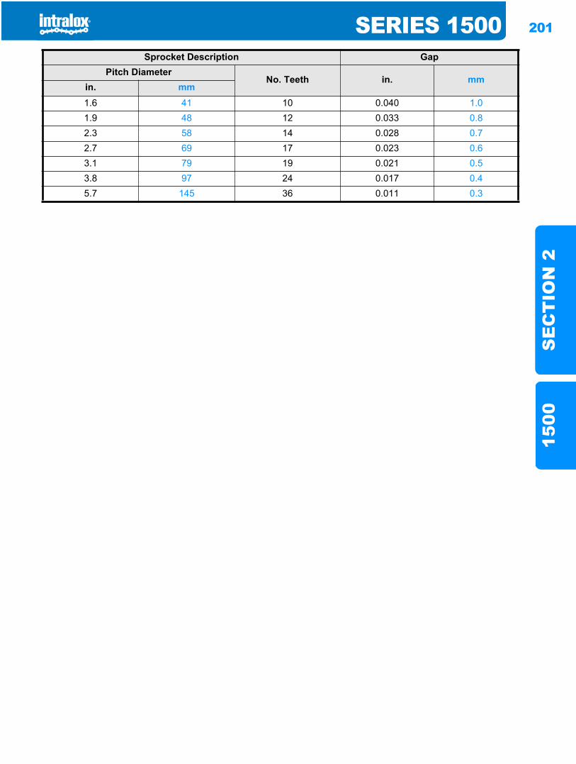
SERIES 1500 201
SE
CT
ION
215
00
Sprocket Description GapPitch Diameter
No. Teeth in. mmin. mm1.6 41 10 0.040 1.01.9 48 12 0.033 0.82.3 58 14 0.028 0.72.7 69 17 0.023 0.63.1 79 19 0.021 0.53.8 97 24 0.017 0.45.7 145 36 0.011 0.3

202 SERIES 1500S
EC
TIO
N 2
1500
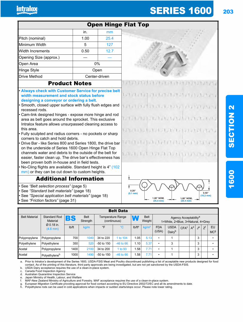
SERIES 1600 203
SE
CT
ION
216
00
Series 16001600
Open Hinge Flat Topin. mm
Pitch (nominal) 1.00 25.4Minimum Width 5 127Width Increments 0.50 12.7Opening Size (approx.) — —Open Area 0%Hinge Style OpenDrive Method Center-driven
Product Notes• Always check with Customer Service for precise belt
width measurement and stock status before designing a conveyor or ordering a belt.
• Smooth, closed upper surface with fully flush edges and recessed rods.
• Cam-link designed hinges - expose more hinge and rod area as belt goes around the sprocket. This exclusive Intralox feature allows unsurpassed cleaning access to this area.
• Fully sculpted and radius corners - no pockets or sharp corners to catch and hold debris.
• Drive Bar - like Series 800 and Series 1800, the drive bar on the underside of Series 1600 Open Hinge Flat Top channels water and debris to the outside of the belt for easier, faster clean up. The drive bar’s effectiveness has been proven both in-house and in field tests.
• No-Cling flights are available. Standard height is 4” (102 mm) or they can be cut down to custom heights.
Additional Information• See “Belt selection process” (page 5)• See “Standard belt materials” (page 18)• See “Special application belt materials” (page 18)• See “Friction factors” (page 31)
Belt DataBelt Material Standard Rod
MaterialØ 0.18 in. (4.6 mm)
BS Belt Strength
Temperature Range (continuous) W Belt
WeightAgency Acceptabilitya
1=White, 2=Blue, 3=Natural, 4=Grey
lb/ft kg/m °F °C lb/ft² kg/m² FDA(USA)
USDADairyb
CFAc Ad Je Zf EUMCg
Polypropylene Polypropylene 700 1040 34 to 220 1 to 104 1.05 5.13 • 1 3 •
Polyethylene Polyethylene 350 520 -50 to 150 -46 to 66 1.10 5.37 • 3 3 •
Acetal Polypropylene 1400 2100 34 to 200 1 to 93 1.58 7.71 • 1 3 •
Acetal Polyethyleneh 1000 1490 -50 to 150 -46 to 66 1.58 7.71 • 1 3 •
a. Prior to Intralox’s development of the Series 1600, USDA-FSIS Meat and Poultry discontinued publishing a list of acceptable new products designed for foodcontact. As of the printing of this literature, third party approvals are being investigated, but are not yet sanctioned by the USDA-FSIS.
b. USDA Dairy acceptance requires the use of a clean-in-place system.c. Canada Food Inspection Agencyd. Australian Quarantine Inspection Servicee. Japan Ministry of Health, Labour, and Welfaref. MAF-New Zealand Ministry of Agriculture and Forestry. MAF acceptance requires the use of a clean-in-place system.g. European Migration Certificate providing approval for food contact according to EU Directive 2002/72/EC and all its amendments to date.h. Polyethylene rods can be used in cold applications when impacts or sudden starts/stops occur. Please note lower rating.
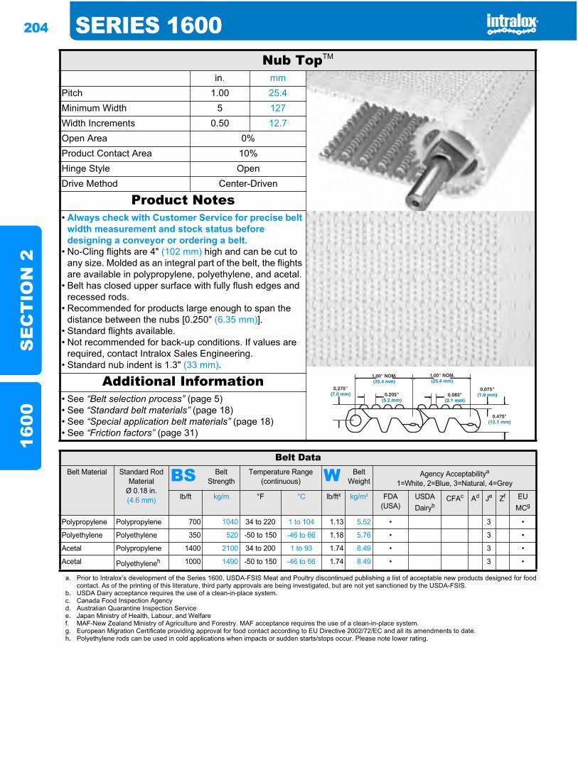
204 SERIES 1600S
EC
TIO
N 2
1600
Nub TopTM
in. mmPitch 1.00 25.4Minimum Width 5 127Width Increments 0.50 12.7Open Area 0%Product Contact Area 10%Hinge Style OpenDrive Method Center-Driven
Product Notes• Always check with Customer Service for precise belt
width measurement and stock status before designing a conveyor or ordering a belt.
• No-Cling flights are 4" (102 mm) high and can be cut to any size. Molded as an integral part of the belt, the flights are available in polypropylene, polyethylene, and acetal.
• Belt has closed upper surface with fully flush edges and recessed rods.
• Recommended for products large enough to span the distance between the nubs [0.250" (6.35 mm)].
• Standard flights available.• Not recommended for back-up conditions. If values are
required, contact Intralox Sales Engineering.• Standard nub indent is 1.3" (33 mm).
Additional Information• See “Belt selection process” (page 5)• See “Standard belt materials” (page 18)• See “Special application belt materials” (page 18)• See “Friction factors” (page 31)
Belt DataBelt Material Standard Rod
MaterialØ 0.18 in. (4.6 mm)
BS Belt Strength
Temperature Range (continuous) W Belt
WeightAgency Acceptabilitya
1=White, 2=Blue, 3=Natural, 4=Grey
lb/ft kg/m °F °C lb/ft² kg/m² FDA(USA)
USDADairyb
CFAc Ad Je Zf EUMCg
Polypropylene Polypropylene 700 1040 34 to 220 1 to 104 1.13 5.52 • 3 •
Polyethylene Polyethylene 350 520 -50 to 150 -46 to 66 1.18 5.76 • 3 •
Acetal Polypropylene 1400 2100 34 to 200 1 to 93 1.74 8.49 • 3 •
Acetal Polyethyleneh 1000 1490 -50 to 150 -46 to 66 1.74 8.49 • 3 •
a. Prior to Intralox’s development of the Series 1600, USDA-FSIS Meat and Poultry discontinued publishing a list of acceptable new products designed for foodcontact. As of the printing of this literature, third party approvals are being investigated, but are not yet sanctioned by the USDA-FSIS.
b. USDA Dairy acceptance requires the use of a clean-in-place system.c. Canada Food Inspection Agencyd. Australian Quarantine Inspection Servicee. Japan Ministry of Health, Labour, and Welfaref. MAF-New Zealand Ministry of Agriculture and Forestry. MAF acceptance requires the use of a clean-in-place system.g. European Migration Certificate providing approval for food contact according to EU Directive 2002/72/EC and all its amendments to date.h. Polyethylene rods can be used in cold applications when impacts or sudden starts/stops occur. Please note lower rating.
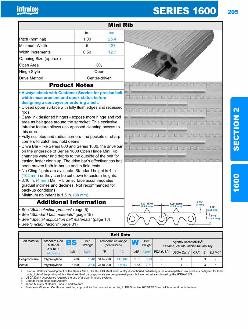
SERIES 1600 205
SE
CT
ION
216
00
Mini Ribin. mm
Pitch (nominal) 1.00 25.4Minimum Width 5 127Width Increments 0.50 12.7Opening Size (approx.) — —Open Area 0%Hinge Style OpenDrive Method Center-driven
Product Notes• Always check with Customer Service for precise belt
width measurement and stock status before designing a conveyor or ordering a belt.
• Closed upper surface with fully flush edges and recessed rods.
• Cam-link designed hinges - expose more hinge and rod area as belt goes around the sprocket. This exclusive Intralox feature allows unsurpassed cleaning access to this area.
• Fully sculpted and radius corners - no pockets or sharp corners to catch and hold debris.
• Drive Bar - like Series 800 and Series 1800, the drive bar on the underside of Series 1600 Open Hinge Mini Rib channels water and debris to the outside of the belt for easier, faster clean up. The drive bar’s effectiveness has been proven both in-house and in field tests.
• No-Cling flights are available. Standard height is 4 in. (102 mm) or they can be cut down to custom heights.
• 0.16 in. (4 mm) Mini Rib on surface accommodates gradual inclines and declines. Not recommended for back-up conditions.
• Minimum rib indent is 1.5 in. (38 mm).
Additional Information• See “Belt selection process” (page 5)• See “Standard belt materials” (page 18)• See “Special application belt materials” (page 18)• See “Friction factors” (page 31)
Belt DataBelt Material Standard Rod
MaterialØ 0.18 in. (4.6 mm)
BS Belt Strength
Temperature Range (continuous) W Belt
WeightAgency Acceptabilitya
1=White, 2=Blue, 3=Natural, 4=Grey
lb/ft kg/m °F °C lb/ft² kg/m² FDA (USA) USDA Dairyb CFAc Jd EU MCe
Polypropylene Polypropylene 700 1040 34 to 220 1 to 104 1.05 5.13 • 1 3 •
Acetal Polypropylene 1400 2100 34 to 200 1 to 93 1.58 7.71 • 1 3 •
a. Prior to Intralox’s development of the Series 1600, USDA-FSIS Meat and Poultry discontinued publishing a list of acceptable new products designed for foodcontact. As of the printing of this literature, third party approvals are being investigated, but are not yet sanctioned by the USDA-FSIS.
b. USDA Dairy acceptance requires the use of a clean-in-place system.c. Canada Food Inspection Agencyd. Japan Ministry of Health, Labour, and Welfaree. European Migration Certificate providing approval for food contact according to EU Directive 2002/72/EC and all its amendments to date.
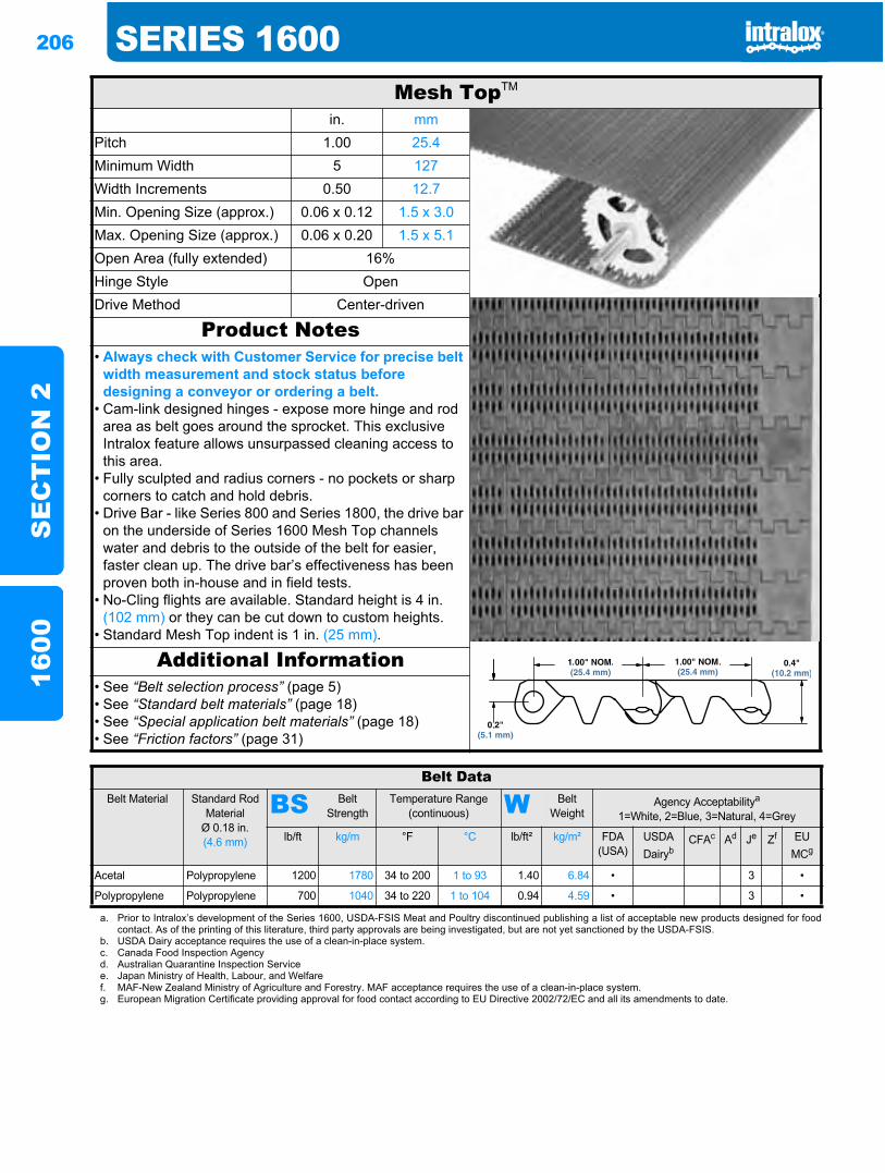
206 SERIES 1600S
EC
TIO
N 2
1600
Mesh TopTM
in. mmPitch 1.00 25.4Minimum Width 5 127Width Increments 0.50 12.7Min. Opening Size (approx.) 0.06 x 0.12 1.5 x 3.0Max. Opening Size (approx.) 0.06 x 0.20 1.5 x 5.1Open Area (fully extended) 16%Hinge Style OpenDrive Method Center-driven
Product Notes• Always check with Customer Service for precise belt
width measurement and stock status before designing a conveyor or ordering a belt.
• Cam-link designed hinges - expose more hinge and rod area as belt goes around the sprocket. This exclusive Intralox feature allows unsurpassed cleaning access to this area.
• Fully sculpted and radius corners - no pockets or sharp corners to catch and hold debris.
• Drive Bar - like Series 800 and Series 1800, the drive bar on the underside of Series 1600 Mesh Top channels water and debris to the outside of the belt for easier, faster clean up. The drive bar’s effectiveness has been proven both in-house and in field tests.
• No-Cling flights are available. Standard height is 4 in. (102 mm) or they can be cut down to custom heights.
• Standard Mesh Top indent is 1 in. (25 mm).
Additional Information• See “Belt selection process” (page 5)• See “Standard belt materials” (page 18)• See “Special application belt materials” (page 18)• See “Friction factors” (page 31)
Belt DataBelt Material Standard Rod
MaterialØ 0.18 in. (4.6 mm)
BS Belt Strength
Temperature Range (continuous) W Belt
WeightAgency Acceptabilitya
1=White, 2=Blue, 3=Natural, 4=Grey
lb/ft kg/m °F °C lb/ft² kg/m² FDA(USA)
USDADairyb
CFAc Ad Je Zf EUMCg
Acetal Polypropylene 1200 1780 34 to 200 1 to 93 1.40 6.84 • 3 •
Polypropylene Polypropylene 700 1040 34 to 220 1 to 104 0.94 4.59 • 3 •
a. Prior to Intralox’s development of the Series 1600, USDA-FSIS Meat and Poultry discontinued publishing a list of acceptable new products designed for foodcontact. As of the printing of this literature, third party approvals are being investigated, but are not yet sanctioned by the USDA-FSIS.
b. USDA Dairy acceptance requires the use of a clean-in-place system.c. Canada Food Inspection Agencyd. Australian Quarantine Inspection Servicee. Japan Ministry of Health, Labour, and Welfaref. MAF-New Zealand Ministry of Agriculture and Forestry. MAF acceptance requires the use of a clean-in-place system.g. European Migration Certificate providing approval for food contact according to EU Directive 2002/72/EC and all its amendments to date.
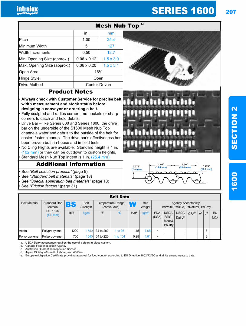
SERIES 1600 207
SE
CT
ION
216
00
Mesh Nub TopTM
in. mmPitch 1.00 25.4Minimum Width 5 127Width Increments 0.50 12.7Min. Opening Size (approx.) 0.06 x 0.12 1.5 x 3.0Max. Opening Size (approx.) 0.06 x 0.20 1.5 x 5.1Open Area 16%Hinge Style OpenDrive Method Center-Driven
Product Notes• Always check with Customer Service for precise belt
width measurement and stock status before designing a conveyor or ordering a belt.
• Fully sculpted and radius corner – no pockets or sharp corners to catch and hold debris.
• Drive Bar – like Series 800 and Series 1800, the drive bar on the underside of the S1600 Mesh Nub Top channels water and debris to the outside of the belt for easier, faster cleanup. The drive bar’s effectiveness has been proven both in-house and in field tests.
• No Cling Flights are available. Standard height is 4 in. (102 mm) or they can be cut down to custom heights.
• Standard Mesh Nub Top indent is 1 in. (25.4 mm).
Additional Information• See “Belt selection process” (page 5)• See “Standard belt materials” (page 18)• See “Special application belt materials” (page 18)• See “Friction factors” (page 31)
Belt DataBelt Material Standard Rod
MaterialØ 0.18 in. (4.6 mm)
BS Belt Strength
Temperature Range (continuous) W Belt
WeightAgency Acceptability:
1=White, 2=Blue, 3=Natural, 4=Grey
lb/ft kg/m °F °C lb/ft² kg/m² FDA(USA)
USDA-FSIS - Meat & Poultry
USDADairya
CFAb Ac Jd EU MCe
Acetal Polypropylene 1200 1780 34 to 200 1 to 93 1.45 7.08 • 3
Polypropylene Polypropylene 700 1040 34 to 220 1 to 104 0.98 4.81 • 3
a. USDA Dairy acceptance requires the use of a clean-in-place-system.b. Canada Food Inspection Agencyc. Australian Quarantine Inspection Serviced. Japan Ministry of Health, Labour, and Welfaree. European Migration Certificate providing approval for food contact according to EU Directive 2002/72/EC and all its amendments to date.
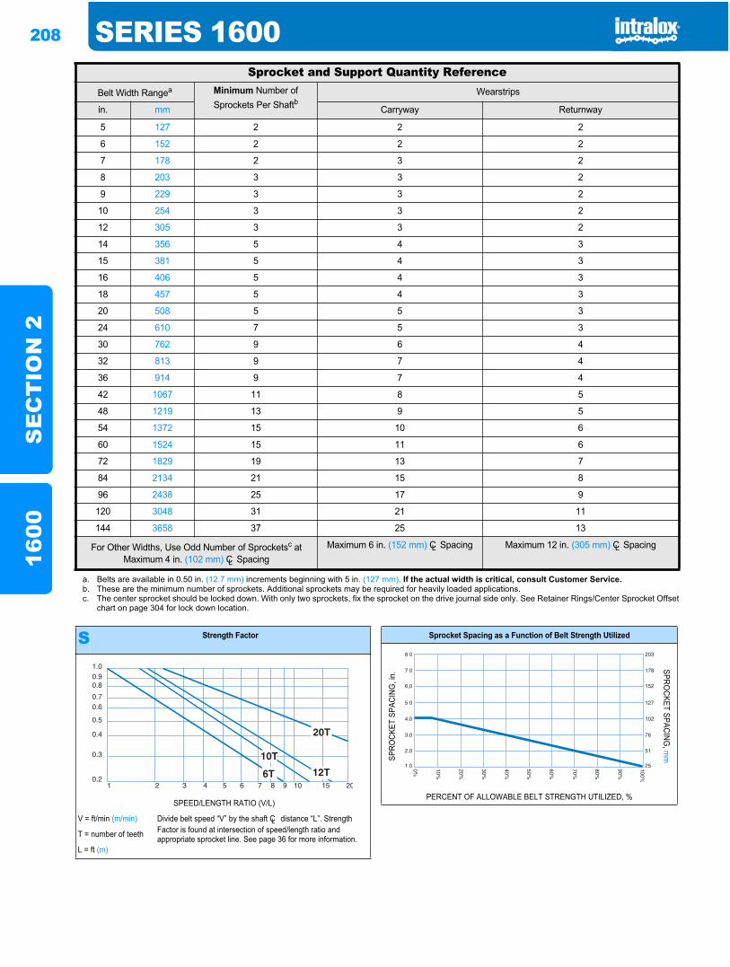
208 SERIES 1600S
EC
TIO
N 2
1600
Sprocket and Support Quantity ReferenceBelt Width Rangea Minimum Number of
Sprockets Per ShaftbWearstrips
in. mm Carryway Returnway
5 127 2 2 2
6 152 2 2 2
7 178 2 3 2
8 203 3 3 2
9 229 3 3 2
10 254 3 3 2
12 305 3 3 2
14 356 5 4 3
15 381 5 4 3
16 406 5 4 3
18 457 5 4 3
20 508 5 5 3
24 610 7 5 3
30 762 9 6 4
32 813 9 7 4
36 914 9 7 4
42 1067 11 8 5
48 1219 13 9 5
54 1372 15 10 6
60 1524 15 11 6
72 1829 19 13 7
84 2134 21 15 8
96 2438 25 17 9
120 3048 31 21 11
144 3658 37 25 13
For Other Widths, Use Odd Number of Sprocketsc at Maximum 4 in. (102 mm) CL Spacing
Maximum 6 in. (152 mm) CL Spacing Maximum 12 in. (305 mm) CL Spacing
a. Belts are available in 0.50 in. (12.7 mm) increments beginning with 5 in. (127 mm). If the actual width is critical, consult Customer Service.b. These are the minimum number of sprockets. Additional sprockets may be required for heavily loaded applications.c. The center sprocket should be locked down. With only two sprockets, fix the sprocket on the drive journal side only. See Retainer Rings/Center Sprocket Offset
chart on page 304 for lock down location.
S Strength Factor
SPEED/LENGTH RATIO (V/L)
V = ft/min (m/min) Divide belt speed “V” by the shaft CL distance “L”. Strength Factor is found at intersection of speed/length ratio and appropriate sprocket line. See page 36 for more information.T = number of teeth
L = ft (m)
1.00.90.8
0.70.6
0.5
0.4
0.3
0.21 2 3 4 5 6 7 8 9 10 15 20
Sprocket Spacing as a Function of Belt Strength Utilized
SPRO
CKET
SPA
CING
, in.
SPROCKET SPACING
, mm
PERCENT OF ALLOWABLE BELT STRENGTH UTILIZED, %
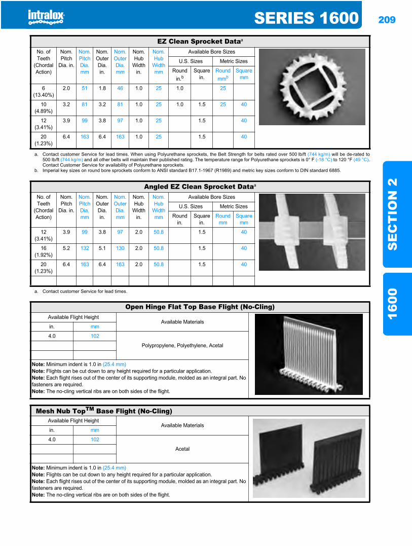
SERIES 1600 209
SE
CT
ION
216
00
EZ Clean Sprocket Dataa
No. of Teeth
(Chordal Action)
Nom. Pitch
Dia. in.
Nom. Pitch Dia. mm
Nom. Outer Dia. in.
Nom. Outer Dia.mm
Nom. Hub
Width in.
Nom. Hub
Width mm
Available Bore Sizes
U.S. Sizes Metric Sizes
Round in.b
Square in.
Round mmb
Square mm
6(13.40%)
2.0 51 1.8 46 1.0 25 1.0 25
10(4.89%)
3.2 81 3.2 81 1.0 25 1.0 1.5 25 40
12(3.41%)
3.9 99 3.8 97 1.0 25 1.5 40
20(1.23%)
6.4 163 6.4 163 1.0 25 1.5 40
a. Contact customer Service for lead times. When using Polyurethane sprockets, the Belt Strength for belts rated over 500 lb/ft (744 kg/m) will be de-rated to500 lb/ft (744 kg/m) and all other belts will maintain their published rating. The temperature range for Polyurethane sprockets is 0° F (-18 °C) to 120 °F (49 °C).Contact Customer Service for availability of Polyurethane sprockets.
b. Imperial key sizes on round bore sprockets conform to ANSI standard B17.1-1967 (R1989) and metric key sizes conform to DIN standard 6885.
Angled EZ Clean Sprocket Dataa
No. of Teeth
(Chordal Action)
Nom. Pitch
Dia. in.
Nom. Pitch Dia. mm
Nom. Outer Dia. in.
Nom. Outer Dia.mm
Nom. Hub
Width in.
Nom. Hub
Width mm
Available Bore Sizes
U.S. Sizes Metric Sizes
Round in.
Square in.
Round mm
Square mm
12(3.41%)
3.9 99 3.8 97 2.0 50.8 1.5 40
16(1.92%)
5.2 132 5.1 130 2.0 50.8 1.5 40
20(1.23%)
6.4 163 6.4 163 2.0 50.8 1.5 40
a. Contact customer Service for lead times.
Open Hinge Flat Top Base Flight (No-Cling)Available Flight Height
Available Materialsin. mm
4.0 102
Polypropylene, Polyethylene, Acetal
Note: Minimum indent is 1.0 in (25.4 mm)Note: Flights can be cut down to any height required for a particular application.Note: Each flight rises out of the center of its supporting module, molded as an integral part. No fasteners are required.Note: The no-cling vertical ribs are on both sides of the flight.
Mesh Nub TopTM Base Flight (No-Cling)Available Flight Height
Available Materialsin. mm
4.0 102
Acetal
Note: Minimum indent is 1.0 in (25.4 mm)Note: Flights can be cut down to any height required for a particular application.Note: Each flight rises out of the center of its supporting module, molded as an integral part. No fasteners are required.Note: The no-cling vertical ribs are on both sides of the flight.
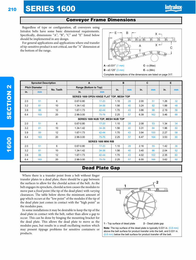
210 SERIES 1600S
EC
TIO
N 2
1600
Regardless of type or configuration, all conveyors usingIntralox belts have some basic dimensional requirements.Specifically, dimensions “A”, “B”, “C” and “E” listed belowshould be implemented in any design.
For general applications and applications where end transferof tip-sensitive product is not critical, use the “A” dimension atthe bottom of the range.
Where there is a transfer point from a belt without fingertransfer plates to a dead plate, there should be a gap betweenthe surfaces to allow for the chordal action of the belt. As thebelt engages its sprockets, chordal action causes the modules tomove past a fixed point (the tip of the dead plate) with varyingclearances. The table below shows the minimum amount ofgap which occurs at the “low point” of the modules if the tip ofthe dead plate just comes in contact with the “high point” asthe modules pass.
In some installations it may be desirable to keep the tip of thedead plate in contact with the belt, rather than allow a gap tooccur. This can be done by hinging the mounting bracket forthe dead plate. This allows the dead plate to move as themodules pass, but results in a small oscillating motion whichmay present tippage problems for sensitive containers orproducts.
Conveyor Frame Dimensions
A - ±0.031” (1 mm) C - ± (Max)
B - ±0.125” (3 mm) E - ± (Min)
Complete descriptions of the dimensions are listed on page 317.
Sprocket Description A B C E
Pitch DiameterNo. Teeth
Range (Bottom to Top)in. mm in. mm in. mm
in. mm in. mm
SERIES 1600 OPEN HINGE FLAT TOP, MESH TOP
2.0 51 6 0.67-0.80 17-20 1.10 28 2.00 51 1.26 32
3.2 81 10 1.34-1.42 34-36 1.56 40 3.24 82 1.88 48
3.9 99 12 1.67-1.73 42-44 1.70 43 3.86 98 2.19 56
6.4 163 20 2.96-3.00 75-76 2.25 57 6.39 162 3.46 88
SERIES 1600 NUB TOP, MESH NUB TOP
2.0 51 6 0.67-0.80 17-20 1.10 28 2.08 53 1.34 34
3.2 81 10 1.34-1.42 34-36 1.56 40 3.31 84 1.96 50
3.9 99 12 1.67-1.73 42-44 1.70 43 3.94 100 2.27 58
6.4 163 20 2.96-3.00 75-76 2.25 57 6.47 164 3.53 90
SERIES 1600 MINI RIB
2.0 51 6 0.67-0.80 17-20 1.10 28 2.16 55 1.42 36
3.2 81 10 1.34-1.42 34-36 1.56 40 3.40 86 2.04 52
3.9 99 12 1.67-1.73 42-44 1.70 43 4.02 102 2.35 60
6.4 163 20 2.96-3.00 75-76 2.25 57 6.55 166 3.62 92
Dead Plate Gap
1 - Top surface of dead plate 2 - Dead plate gap
Note: The top surface of the dead plate is typically 0.031 in. (0.8 mm)above the belt surface for product transfer onto the belt, and 0.031 in. (0.8 mm) below the belt surface for product transfer off the belt.
21
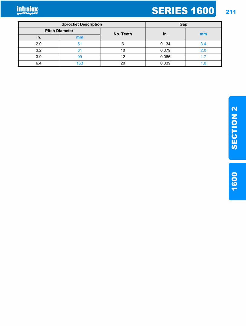
SERIES 1600 211
SE
CT
ION
216
00
Sprocket Description GapPitch Diameter
No. Teeth in. mmin. mm2.0 51 6 0.134 3.43.2 81 10 0.079 2.03.9 99 12 0.066 1.76.4 163 20 0.039 1.0

212 SERIES 1600S
EC
TIO
N 2
1600
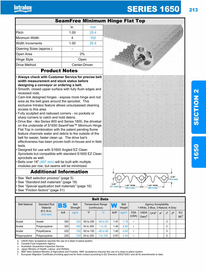
SERIES 1650 213
SE
CT
ION
216
50
Series 16501650
SeamFree Minimum Hinge Flat Topin. mm
Pitch 1.00 25.4Minimum Width 4 102Width Increments 1.00 25.4Opening Sizes (approx.) - -Open Area 0%Hinge Style OpenDrive Method Center-Driven
Product Notes• Always check with Customer Service for precise belt
width measurement and stock status before designing a conveyor or ordering a belt.
• Smooth, closed upper surface with fully flush edges and recessed rods.
• Cam-link designed hinges - expose more hinge and rod area as the belt goes around the sprocket. This exclusive Intralox feature allows unsurpassed cleaning access to this area.
• Fully sculpted and radiused corners - no pockets or sharp corners to catch and hold debris.
• Drive Bar - like Series 800 and Series 1800, the drivebar on the underside of S1650 SeamFree™ Minimum Hinge Flat Top in combination with the patent pending flume feature channels water and debris to the outside of the belt for easier, faster clean up. The drive bar's effectiveness has been proven both in-house and in field tests.
• Designed for use with S1600 Angled EZ Clean Sprockets but compatible with standard S1600 EZ Clean sprockets as well.
• Belts over 18" (457 mm) will be built with multiple modules per row, but seams will be minimized.
Additional Information• See “Belt selection process” (page 5)• See “Standard belt materials” (page 18)• See “Special application belt materials” (page 18)• See “Friction factors” (page 31)
Belt DataBelt Material Standard Rod
MaterialØ 0.18 in. (4.6 mm)
BS Belt Strength
Temperature Range (continuous) W Belt
WeightAgency Acceptability
1-White, 2-Blue, 3-Natural, 4-Grey
lb/ft kg/m °F °C lb/ft² kg/m² FDA (USA)
USDADairya
CFAb Ac Jd Ze EU MCf
Acetal Acetal 350 520 -50 to 200 -46 to 93 1.47 7.18 • 3
Acetal Polypropylene 325 480 34 to 200 1 to 93 1.40 6.84 • 3
Acetal Polyethylene 225 330 -50 to 150 -46 to 66 1.40 6.83 • 3
Polypropylene Polypropylene 225 330 34 to 220 1 to 104 0.91 4.44 • 3
a. USDA Dairy acceptance requires the use of a clean-in-place-system.b. Canada Food Inspection Agencyc. Australian Quarantine Inspection Serviced. Japan Ministry of Health, Labour, and Welfaree. MAF-New Zealand Ministry of Agriculture and Forestry. MAF acceptance requires the use of a clean-in-place system.f. European Migration Certificate providing approval for food contact according to EU Directive 2002/72/EC and all its amendments to date.
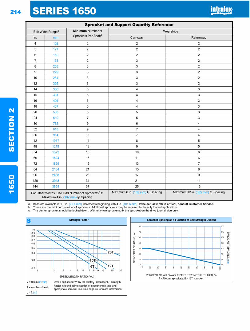
214 SERIES 1650S
EC
TIO
N 2
1650
Sprocket and Support Quantity ReferenceBelt Width Rangea Minimum Number of
Sprockets Per ShaftbWearstrips
in. mm Carryway Returnway
4 102 2 2 2
5 127 2 2 2
6 152 2 2 2
7 178 2 3 2
8 203 3 3 2
9 229 3 3 2
10 254 3 3 2
12 305 3 3 2
14 356 5 4 3
15 381 5 4 3
16 406 5 4 3
18 457 5 4 3
20 508 5 5 3
24 610 7 5 3
30 762 9 6 4
32 813 9 7 4
36 914 9 7 4
42 1067 11 8 5
48 1219 13 9 5
54 1372 15 10 6
60 1524 15 11 6
72 1829 19 13 7
84 2134 21 15 8
96 2438 25 17 9
120 3048 31 21 11
144 3658 37 25 13
For Other Widths, Use Odd Number of Sprocketsc at Maximum 4 in. (102 mm) CL Spacing
Maximum 6 in. (152 mm) CL Spacing Maximum 12 in. (305 mm) CL Spacing
a. Belts are available in 1.0 in. (25.4 mm) increments beginning with 4 in. (101.6 mm). If the actual width is critical, consult Customer Service.b. These are the minimum number of sprockets. Additional sprockets may be required for heavily loaded applications.c. The center sprocket should be locked down. With only two sprockets, fix the sprocket on the drive journal side only.
S Strength Factor
SPEED/LENGTH RATIO (V/L)
V = ft/min (m/min) Divide belt speed “V” by the shaft CL distance “L”. Strength Factor is found at intersection of speed/length ratio and appropriate sprocket line. See page 36 for more information.T = number of teeth
L = ft (m)
1.00.90.8
0.70.6
0.5
0.4
0.3
0.21 2 3 4 5 6 7 8 9 10 15 20
Sprocket Spacing as a Function of Belt Strength Utilized
SPRO
CKET
SPA
CING
, in.
SPROCKET SPACING
, mm
PERCENT OF ALLOWABLE BELT STRENGTH UTILIZED, %A - Allother sprockets. B - 16T sprocket.
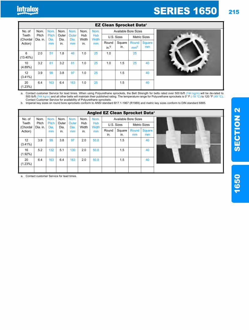
SERIES 1650 215
SE
CT
ION
216
50
EZ Clean Sprocket Dataa
No. of Teeth
(Chordal Action)
Nom. Pitch
Dia. in.
Nom. Pitch Dia. mm
Nom. Outer Dia. in.
Nom. Outer Dia.mm
Nom. Hub
Width in.
Nom. Hub
Width mm
Available Bore Sizes
U.S. Sizes Metric Sizes
Round in.b
Square in.
Round mmb
Square mm
6(13.40%)
2.0 51 1.8 46 1.0 25 1.0 25
10(4.89%)
3.2 81 3.2 81 1.0 25 1.0 1.5 25 40
12(3.41%)
3.9 99 3.8 97 1.0 25 1.5 40
20(1.23%)
6.4 163 6.4 163 1.0 25 1.5 40
a. Contact customer Service for lead times. When using Polyurethane sprockets, the Belt Strength for belts rated over 500 lb/ft (744 kg/m) will be de-rated to500 lb/ft (744 kg/m) and all other belts will maintain their published rating. The temperature range for Polyurethane sprockets is 0° F (-18 °C) to 120 °F (49 °C).Contact Customer Service for availability of Polyurethane sprockets.
b. Imperial key sizes on round bore sprockets conform to ANSI standard B17.1-1967 (R1989) and metric key sizes conform to DIN standard 6885.
Angled EZ Clean Sprocket Dataa
No. of Teeth
(Chordal Action)
Nom. Pitch
Dia. in.
Nom. Pitch Dia. mm
Nom. Outer Dia. in.
Nom. Outer Dia.mm
Nom. Hub
Width in.
Nom. Hub
Width mm
Available Bore Sizes
U.S. Sizes Metric Sizes
Round in.
Square in.
Round mm
Square mm
12(3.41%)
3.9 99 3.8 97 2.0 50.8 1.5 40
16(1.92%)
5.2 132 5.1 130 2.0 50.8 1.5 40
20(1.23%)
6.4 163 6.4 163 2.0 50.8 1.5 40
a. Contact customer Service for lead times.
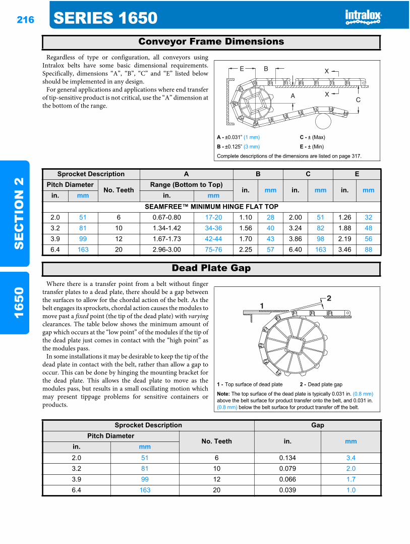
216 SERIES 1650S
EC
TIO
N 2
1650
Regardless of type or configuration, all conveyors usingIntralox belts have some basic dimensional requirements.Specifically, dimensions “A”, “B”, “C” and “E” listed belowshould be implemented in any design.
For general applications and applications where end transferof tip-sensitive product is not critical, use the “A” dimension atthe bottom of the range.
Where there is a transfer point from a belt without fingertransfer plates to a dead plate, there should be a gap betweenthe surfaces to allow for the chordal action of the belt. As thebelt engages its sprockets, chordal action causes the modules tomove past a fixed point (the tip of the dead plate) with varyingclearances. The table below shows the minimum amount ofgap which occurs at the “low point” of the modules if the tip ofthe dead plate just comes in contact with the “high point” asthe modules pass.
In some installations it may be desirable to keep the tip of thedead plate in contact with the belt, rather than allow a gap tooccur. This can be done by hinging the mounting bracket forthe dead plate. This allows the dead plate to move as themodules pass, but results in a small oscillating motion whichmay present tippage problems for sensitive containers orproducts.
Conveyor Frame Dimensions
A - ±0.031” (1 mm) C - ± (Max)
B - ±0.125” (3 mm) E - ± (Min)
Complete descriptions of the dimensions are listed on page 317.
Sprocket Description A B C EPitch Diameter
No. TeethRange (Bottom to Top)
in. mm in. mm in. mmin. mm in. mm
SEAMFREE™ MINIMUM HINGE FLAT TOP2.0 51 6 0.67-0.80 17-20 1.10 28 2.00 51 1.26 323.2 81 10 1.34-1.42 34-36 1.56 40 3.24 82 1.88 483.9 99 12 1.67-1.73 42-44 1.70 43 3.86 98 2.19 566.4 163 20 2.96-3.00 75-76 2.25 57 6.40 163 3.46 88
Dead Plate Gap
1 - Top surface of dead plate 2 - Dead plate gap
Note: The top surface of the dead plate is typically 0.031 in. (0.8 mm)above the belt surface for product transfer onto the belt, and 0.031 in. (0.8 mm) below the belt surface for product transfer off the belt.
21
Sprocket Description GapPitch Diameter
No. Teeth in. mmin. mm2.0 51 6 0.134 3.43.2 81 10 0.079 2.03.9 99 12 0.066 1.76.4 163 20 0.039 1.0
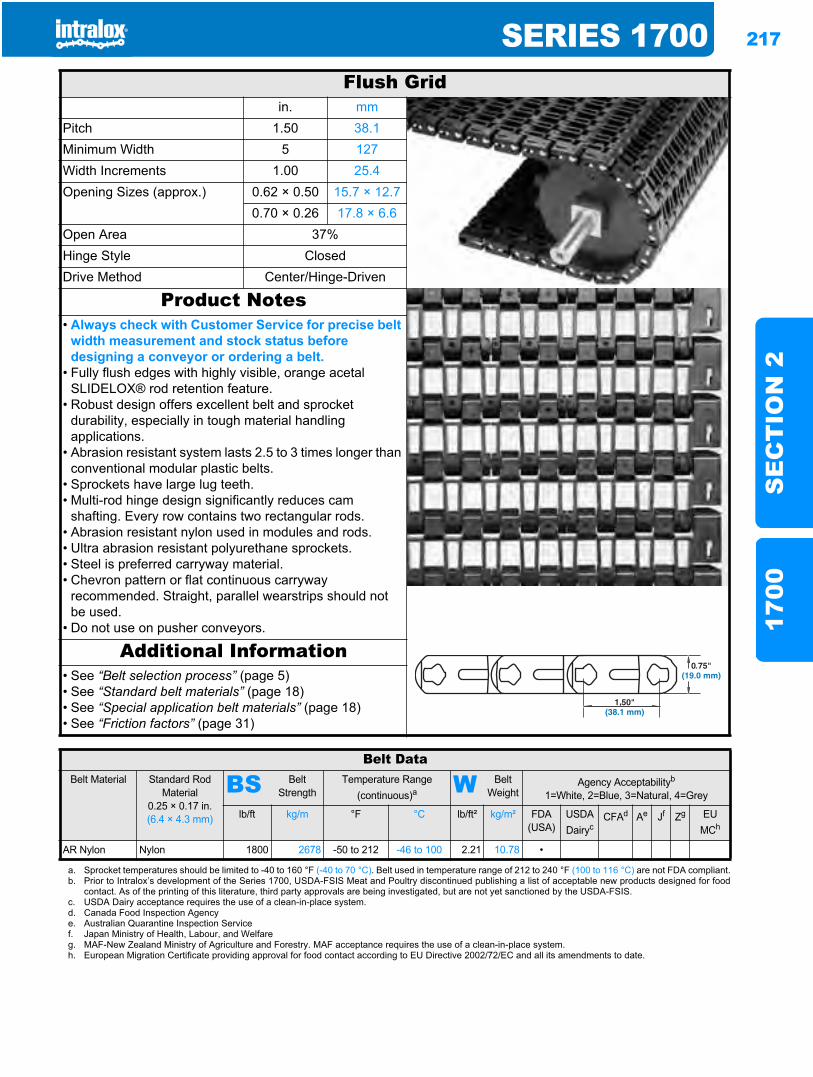
SERIES 1700 217
SE
CT
ION
217
00
Series 17001700
Flush Gridin. mm
Pitch 1.50 38.1Minimum Width 5 127Width Increments 1.00 25.4Opening Sizes (approx.) 0.62 × 0.50 15.7 × 12.7
0.70 × 0.26 17.8 × 6.6Open Area 37%Hinge Style ClosedDrive Method Center/Hinge-Driven
Product Notes• Always check with Customer Service for precise belt
width measurement and stock status before designing a conveyor or ordering a belt.
• Fully flush edges with highly visible, orange acetal SLIDELOX® rod retention feature.
• Robust design offers excellent belt and sprocket durability, especially in tough material handling applications.
• Abrasion resistant system lasts 2.5 to 3 times longer than conventional modular plastic belts.
• Sprockets have large lug teeth.• Multi-rod hinge design significantly reduces cam
shafting. Every row contains two rectangular rods.• Abrasion resistant nylon used in modules and rods.• Ultra abrasion resistant polyurethane sprockets.• Steel is preferred carryway material.• Chevron pattern or flat continuous carryway
recommended. Straight, parallel wearstrips should not be used.
• Do not use on pusher conveyors.
Additional Information• See “Belt selection process” (page 5)• See “Standard belt materials” (page 18)• See “Special application belt materials” (page 18)• See “Friction factors” (page 31)
Belt DataBelt Material Standard Rod
Material0.25 × 0.17 in. (6.4 × 4.3 mm)
BS Belt Strength
Temperature Range (continuous)a W Belt
WeightAgency Acceptabilityb
1=White, 2=Blue, 3=Natural, 4=Grey
lb/ft kg/m °F °C lb/ft² kg/m² FDA(USA)
USDADairyc
CFAd Ae Jf Zg EU MCh
AR Nylon Nylon 1800 2678 -50 to 212 -46 to 100 2.21 10.78 •
a. Sprocket temperatures should be limited to -40 to 160 °F (-40 to 70 °C). Belt used in temperature range of 212 to 240 °F (100 to 116 °C) are not FDA compliant.b. Prior to Intralox’s development of the Series 1700, USDA-FSIS Meat and Poultry discontinued publishing a list of acceptable new products designed for food
contact. As of the printing of this literature, third party approvals are being investigated, but are not yet sanctioned by the USDA-FSIS.c. USDA Dairy acceptance requires the use of a clean-in-place system.d. Canada Food Inspection Agencye. Australian Quarantine Inspection Servicef. Japan Ministry of Health, Labour, and Welfareg. MAF-New Zealand Ministry of Agriculture and Forestry. MAF acceptance requires the use of a clean-in-place system.h. European Migration Certificate providing approval for food contact according to EU Directive 2002/72/EC and all its amendments to date.
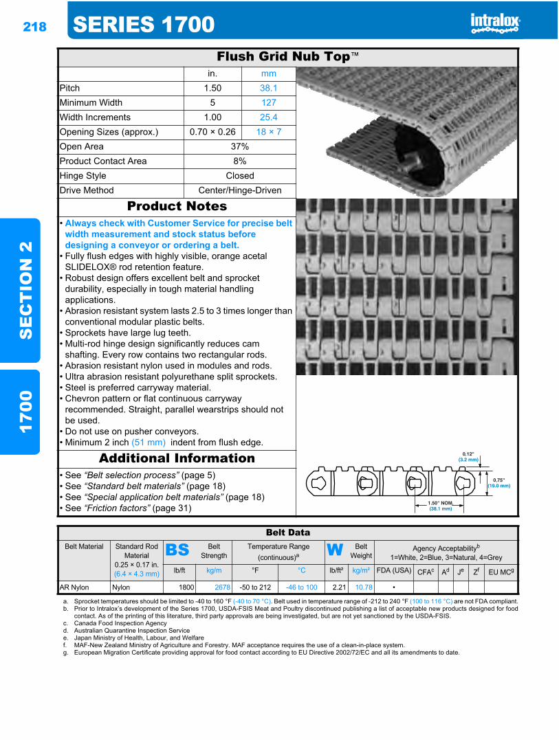
218 SERIES 1700S
EC
TIO
N 2
1700
Flush Grid Nub Top™
in. mmPitch 1.50 38.1Minimum Width 5 127Width Increments 1.00 25.4Opening Sizes (approx.) 0.70 × 0.26 18 × 7Open Area 37%Product Contact Area 8%Hinge Style ClosedDrive Method Center/Hinge-Driven
Product Notes• Always check with Customer Service for precise belt
width measurement and stock status before designing a conveyor or ordering a belt.
• Fully flush edges with highly visible, orange acetal SLIDELOX® rod retention feature.
• Robust design offers excellent belt and sprocket durability, especially in tough material handling applications.
• Abrasion resistant system lasts 2.5 to 3 times longer than conventional modular plastic belts.
• Sprockets have large lug teeth.• Multi-rod hinge design significantly reduces cam
shafting. Every row contains two rectangular rods.• Abrasion resistant nylon used in modules and rods.• Ultra abrasion resistant polyurethane split sprockets.• Steel is preferred carryway material.• Chevron pattern or flat continuous carryway
recommended. Straight, parallel wearstrips should not be used.
• Do not use on pusher conveyors.• Minimum 2 inch (51 mm) indent from flush edge.
Additional Information• See “Belt selection process” (page 5)• See “Standard belt materials” (page 18)• See “Special application belt materials” (page 18)• See “Friction factors” (page 31)
Belt DataBelt Material Standard Rod
Material0.25 × 0.17 in. (6.4 × 4.3 mm)
BS Belt Strength
Temperature Range (continuous)a W Belt
WeightAgency Acceptabilityb
1=White, 2=Blue, 3=Natural, 4=Grey
lb/ft kg/m °F °C lb/ft² kg/m² FDA (USA) CFAc Ad Je Zf EU MCg
AR Nylon Nylon 1800 2678 -50 to 212 -46 to 100 2.21 10.78 •
a. Sprocket temperatures should be limited to -40 to 160 °F (-40 to 70 °C). Belt used in temperature range of -212 to 240 °F (100 to 116 °C) are not FDA compliant.b. Prior to Intralox’s development of the Series 1700, USDA-FSIS Meat and Poultry discontinued publishing a list of acceptable new products designed for food
contact. As of the printing of this literature, third party approvals are being investigated, but are not yet sanctioned by the USDA-FSIS.c. Canada Food Inspection Agencyd. Australian Quarantine Inspection Servicee. Japan Ministry of Health, Labour, and Welfaref. MAF-New Zealand Ministry of Agriculture and Forestry. MAF acceptance requires the use of a clean-in-place system.g. European Migration Certificate providing approval for food contact according to EU Directive 2002/72/EC and all its amendments to date.
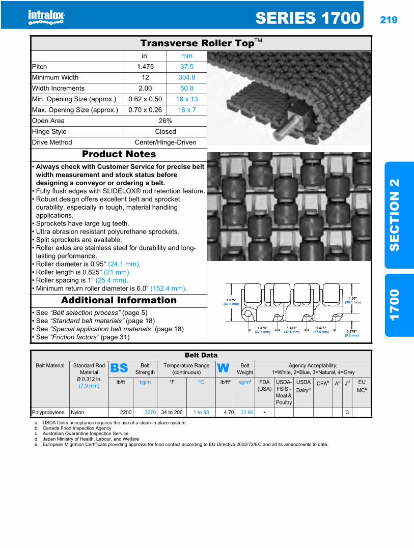
SERIES 1700 219
SE
CT
ION
217
00
Transverse Roller TopTM
in. mmPitch 1.475 37.5Minimum Width 12 304.8Width Increments 2.00 50.8Min. Opening Size (approx.) 0.62 x 0.50 16 x 13Max. Opening Size (approx.) 0.70 x 0.26 18 x 7Open Area 26%Hinge Style ClosedDrive Method Center/Hinge-Driven
Product Notes• Always check with Customer Service for precise belt
width measurement and stock status before designing a conveyor or ordering a belt.
• Fully flush edges with SLIDELOX® rod retention feature.• Robust design offers excellent belt and sprocket
durability, especially in tough, material handling applications.
• Sprockets have large lug teeth.• Ultra abrasion resistant polyurethane sprockets.• Split sprockets are available.• Roller axles are stainless steel for durability and long-
lasting performance.• Roller diameter is 0.95" (24.1 mm).• Roller length is 0.825" (21 mm).• Roller spacing is 1" (25.4 mm).• Minimum return roller diameter is 6.0" (152.4 mm).
Additional Information• See “Belt selection process” (page 5)• See “Standard belt materials” (page 18)• See “Special application belt materials” (page 18)• See “Friction factors” (page 31)
Belt DataBelt Material Standard Rod
MaterialØ 0.312 in. (7.9 mm)
BS Belt Strength
Temperature Range (continuous) W Belt
WeightAgency Acceptability:
1=White, 2=Blue, 3=Natural, 4=Grey
lb/ft kg/m °F °C lb/ft² kg/m² FDA(USA)
USDA-FSIS - Meat & Poultry
USDADairya
CFAb Ac Jd EU MCe
Polypropylene Nylon 2200 3270 34 to 200 1 to 93 4.70 22.96 • 3
a. USDA Dairy acceptance requires the use of a clean-in-place-system.b. Canada Food Inspection Agencyc. Australian Quarantine Inspection Serviced. Japan Ministry of Health, Labour, and Welfaree. European Migration Certificate providing approval for food contact according to EU Directive 2002/72/EC and all its amendments to date.
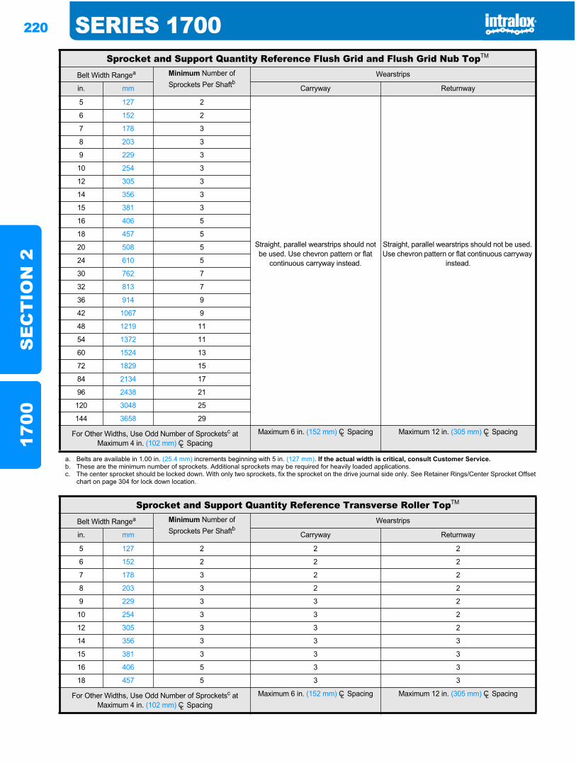
220 SERIES 1700S
EC
TIO
N 2
1700
Sprocket and Support Quantity Reference Flush Grid and Flush Grid Nub TopTM
Belt Width Rangea Minimum Number of Sprockets Per Shaftb
Wearstrips
in. mm Carryway Returnway
5 127 2
Straight, parallel wearstrips should not be used. Use chevron pattern or flat
continuous carryway instead.
Straight, parallel wearstrips should not be used. Use chevron pattern or flat continuous carryway
instead.
6 152 2
7 178 3
8 203 3
9 229 3
10 254 3
12 305 3
14 356 3
15 381 3
16 406 5
18 457 5
20 508 5
24 610 5
30 762 7
32 813 7
36 914 9
42 1067 9
48 1219 11
54 1372 11
60 1524 13
72 1829 15
84 2134 17
96 2438 21
120 3048 25
144 3658 29
For Other Widths, Use Odd Number of Sprocketsc at Maximum 4 in. (102 mm) CL Spacing
Maximum 6 in. (152 mm) CL Spacing Maximum 12 in. (305 mm) CL Spacing
a. Belts are available in 1.00 in. (25.4 mm) increments beginning with 5 in. (127 mm). If the actual width is critical, consult Customer Service.b. These are the minimum number of sprockets. Additional sprockets may be required for heavily loaded applications.c. The center sprocket should be locked down. With only two sprockets, fix the sprocket on the drive journal side only. See Retainer Rings/Center Sprocket Offset
chart on page 304 for lock down location.
Sprocket and Support Quantity Reference Transverse Roller TopTM
Belt Width Rangea Minimum Number of Sprockets Per Shaftb
Wearstrips
in. mm Carryway Returnway
5 127 2 2 2
6 152 2 2 2
7 178 3 2 2
8 203 3 2 2
9 229 3 3 2
10 254 3 3 2
12 305 3 3 2
14 356 3 3 3
15 381 3 3 3
16 406 5 3 3
18 457 5 3 3
For Other Widths, Use Odd Number of Sprocketsc at Maximum 4 in. (102 mm) CL Spacing
Maximum 6 in. (152 mm) CL Spacing Maximum 12 in. (305 mm) CL Spacing
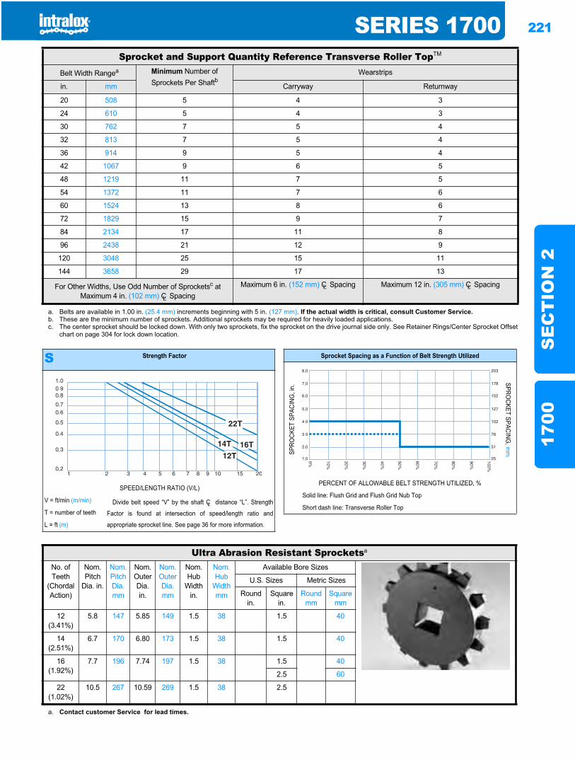
SERIES 1700 221
SE
CT
ION
217
00
20 508 5 4 3
24 610 5 4 3
30 762 7 5 4
32 813 7 5 4
36 914 9 5 4
42 1067 9 6 5
48 1219 11 7 5
54 1372 11 7 6
60 1524 13 8 6
72 1829 15 9 7
84 2134 17 11 8
96 2438 21 12 9
120 3048 25 15 11
144 3658 29 17 13
a. Belts are available in 1.00 in. (25.4 mm) increments beginning with 5 in. (127 mm). If the actual width is critical, consult Customer Service.b. These are the minimum number of sprockets. Additional sprockets may be required for heavily loaded applications.c. The center sprocket should be locked down. With only two sprockets, fix the sprocket on the drive journal side only. See Retainer Rings/Center Sprocket Offset
chart on page 304 for lock down location.
Sprocket and Support Quantity Reference Transverse Roller TopTM
Belt Width Rangea Minimum Number of Sprockets Per Shaftb
Wearstrips
in. mm Carryway Returnway
For Other Widths, Use Odd Number of Sprocketsc at Maximum 4 in. (102 mm) CL Spacing
Maximum 6 in. (152 mm) CL Spacing Maximum 12 in. (305 mm) CL Spacing
S Strength Factor
SPEED/LENGTH RATIO (V/L)
V = ft/min (m/min) Divide belt speed “V” by the shaft CL distance “L”. Strength
Factor is found at intersection of speed/length ratio and
appropriate sprocket line. See page 36 for more information.
T = number of teeth
L = ft (m)
Sprocket Spacing as a Function of Belt Strength Utilized
SPRO
CKET
SPA
CING
, in.
SPROCKET SPACING
, mm
PERCENT OF ALLOWABLE BELT STRENGTH UTILIZED, %
Solid line: Flush Grid and Flush Grid Nub Top
Short dash line: Transverse Roller Top
Ultra Abrasion Resistant Sprocketsa
No. of Teeth
(Chordal Action)
Nom. Pitch
Dia. in.
Nom. Pitch Dia. mm
Nom. Outer Dia. in.
Nom. Outer Dia.mm
Nom. Hub
Width in.
Nom. Hub
Width mm
Available Bore Sizes
U.S. Sizes Metric Sizes
Round in.
Square in.
Round mm
Square mm
12(3.41%)
5.8 147 5.85 149 1.5 38 1.5 40
14(2.51%)
6.7 170 6.80 173 1.5 38 1.5 40
16(1.92%)
7.7 196 7.74 197 1.5 38 1.5 40
2.5 60
22(1.02%)
10.5 267 10.59 269 1.5 38 2.5
a. Contact customer Service for lead times.
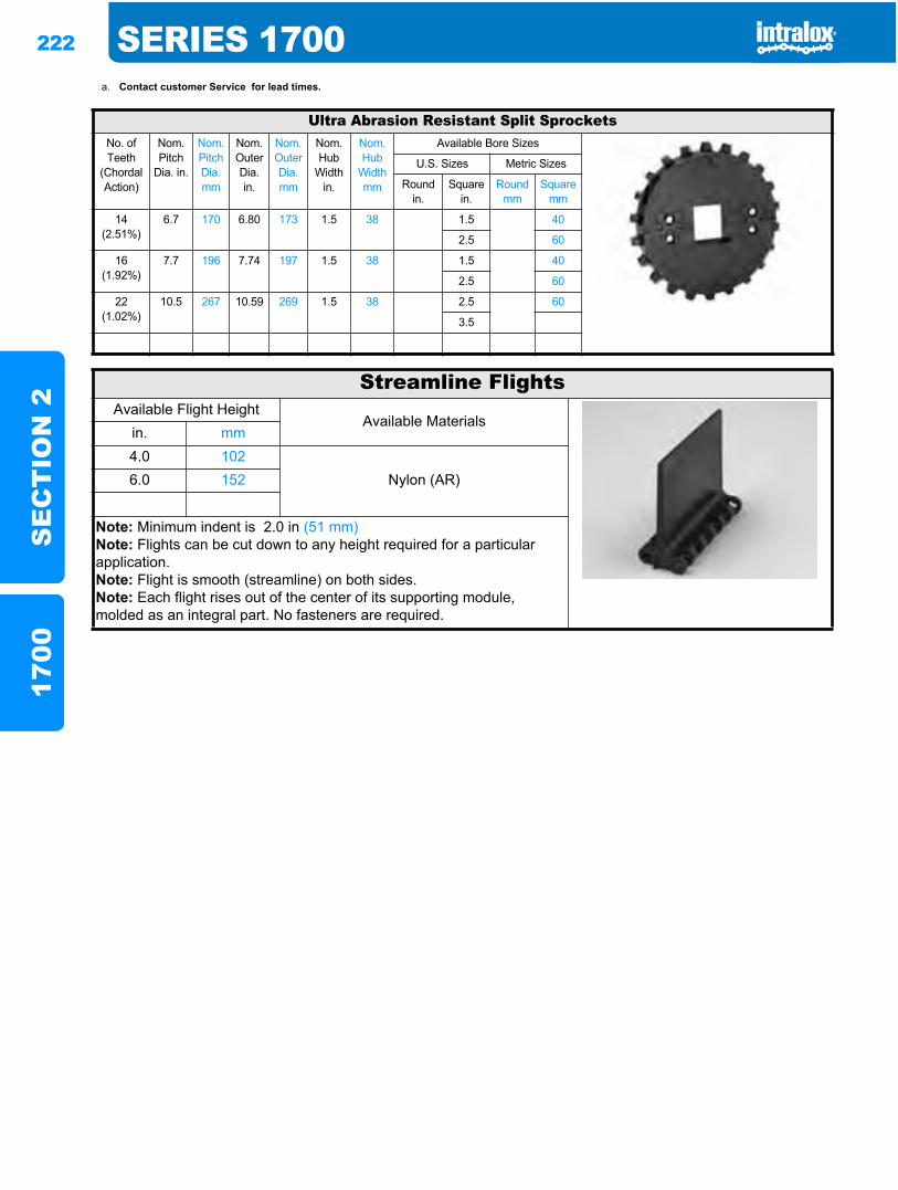
222 SERIES 1700S
EC
TIO
N 2
1700
a. Contact customer Service for lead times.
Ultra Abrasion Resistant Split SprocketsNo. of Teeth
(Chordal Action)
Nom. Pitch
Dia. in.
Nom. Pitch Dia. mm
Nom. Outer Dia. in.
Nom. Outer Dia.mm
Nom. Hub
Width in.
Nom. Hub
Width mm
Available Bore Sizes
U.S. Sizes Metric Sizes
Round in.
Square in.
Round mm
Square mm
14(2.51%)
6.7 170 6.80 173 1.5 38 1.5 40
2.5 60
16(1.92%)
7.7 196 7.74 197 1.5 38 1.5 40
2.5 60
22(1.02%)
10.5 267 10.59 269 1.5 38 2.5 60
3.5
Streamline FlightsAvailable Flight Height
Available Materialsin. mm4.0 102
Nylon (AR)6.0 152
Note: Minimum indent is 2.0 in (51 mm)Note: Flights can be cut down to any height required for a particular application.Note: Flight is smooth (streamline) on both sides.Note: Each flight rises out of the center of its supporting module, molded as an integral part. No fasteners are required.
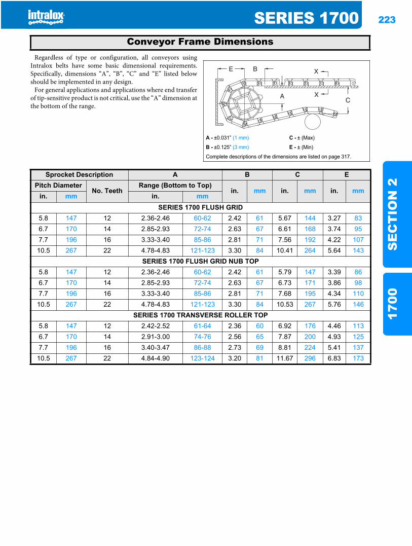
SERIES 1700 223
SE
CT
ION
217
00
Regardless of type or configuration, all conveyors usingIntralox belts have some basic dimensional requirements.Specifically, dimensions “A”, “B”, “C” and “E” listed belowshould be implemented in any design.
For general applications and applications where end transferof tip-sensitive product is not critical, use the “A” dimension atthe bottom of the range.
Conveyor Frame Dimensions
A - ±0.031” (1 mm) C - ± (Max)
B - ±0.125” (3 mm) E - ± (Min)
Complete descriptions of the dimensions are listed on page 317.
Sprocket Description A B C EPitch Diameter
No. TeethRange (Bottom to Top)
in. mm in. mm in. mmin. mm in. mm
SERIES 1700 FLUSH GRID5.8 147 12 2.36-2.46 60-62 2.42 61 5.67 144 3.27 836.7 170 14 2.85-2.93 72-74 2.63 67 6.61 168 3.74 957.7 196 16 3.33-3.40 85-86 2.81 71 7.56 192 4.22 10710.5 267 22 4.78-4.83 121-123 3.30 84 10.41 264 5.64 143
SERIES 1700 FLUSH GRID NUB TOP5.8 147 12 2.36-2.46 60-62 2.42 61 5.79 147 3.39 866.7 170 14 2.85-2.93 72-74 2.63 67 6.73 171 3.86 987.7 196 16 3.33-3.40 85-86 2.81 71 7.68 195 4.34 11010.5 267 22 4.78-4.83 121-123 3.30 84 10.53 267 5.76 146
SERIES 1700 TRANSVERSE ROLLER TOP5.8 147 12 2.42-2.52 61-64 2.36 60 6.92 176 4.46 1136.7 170 14 2.91-3.00 74-76 2.56 65 7.87 200 4.93 1257.7 196 16 3.40-3.47 86-88 2.73 69 8.81 224 5.41 13710.5 267 22 4.84-4.90 123-124 3.20 81 11.67 296 6.83 173
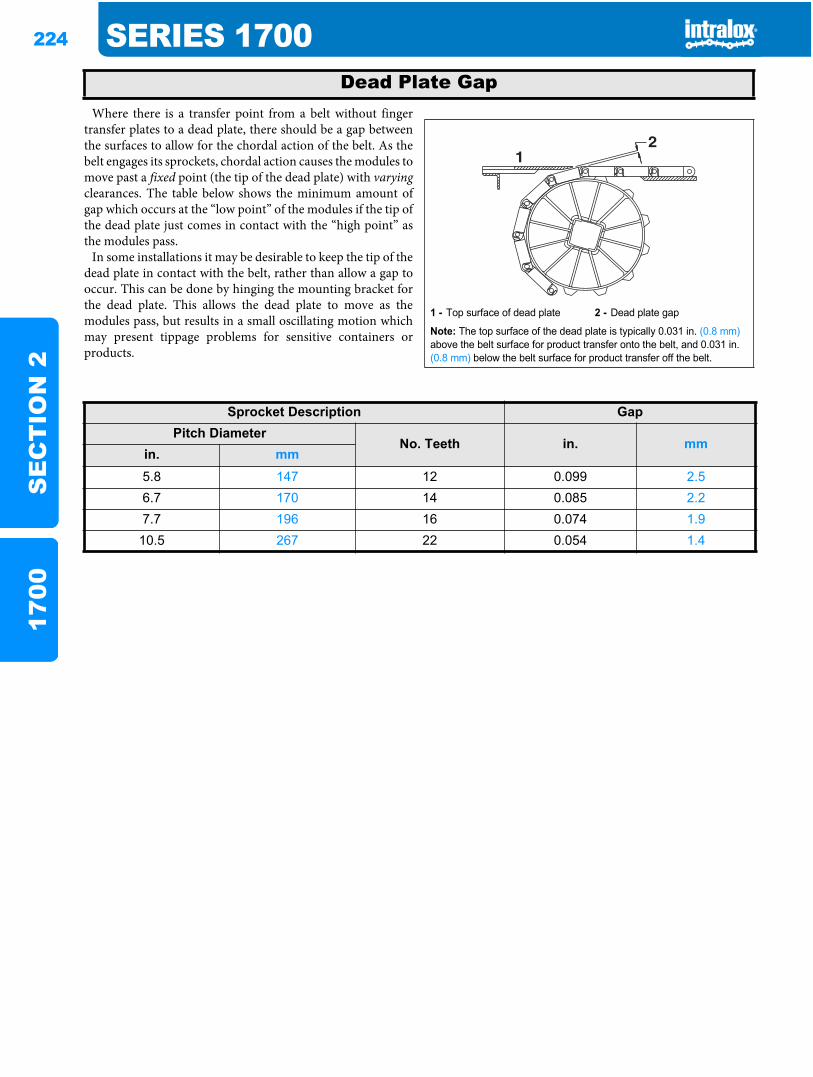
224 SERIES 1700S
EC
TIO
N 2
1700
Where there is a transfer point from a belt without fingertransfer plates to a dead plate, there should be a gap betweenthe surfaces to allow for the chordal action of the belt. As thebelt engages its sprockets, chordal action causes the modules tomove past a fixed point (the tip of the dead plate) with varyingclearances. The table below shows the minimum amount ofgap which occurs at the “low point” of the modules if the tip ofthe dead plate just comes in contact with the “high point” asthe modules pass.
In some installations it may be desirable to keep the tip of thedead plate in contact with the belt, rather than allow a gap tooccur. This can be done by hinging the mounting bracket forthe dead plate. This allows the dead plate to move as themodules pass, but results in a small oscillating motion whichmay present tippage problems for sensitive containers orproducts.
Dead Plate Gap
1 - Top surface of dead plate 2 - Dead plate gap
Note: The top surface of the dead plate is typically 0.031 in. (0.8 mm)above the belt surface for product transfer onto the belt, and 0.031 in. (0.8 mm) below the belt surface for product transfer off the belt.
21
Sprocket Description GapPitch Diameter
No. Teeth in. mmin. mm5.8 147 12 0.099 2.56.7 170 14 0.085 2.27.7 196 16 0.074 1.9
10.5 267 22 0.054 1.4
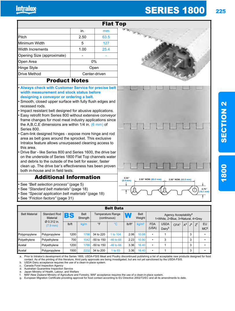
SERIES 1800 225
SE
CT
ION
218
00
Series 18001800
Flat Topin. mm
Pitch 2.50 63.5Minimum Width 5 127Width Increments 1.00 25.4Opening Size (approximate) - -Open Area 0%Hinge Style OpenDrive Method Center-driven
Product Notes• Always check with Customer Service for precise belt
width measurement and stock status before designing a conveyor or ordering a belt.
• Smooth, closed upper surface with fully flush edges and recessed rods.
• Impact resistant belt designed for abusive applications.• Easy retrofit from Series 800 without extensive conveyor
frame changes for most meat industry applications since the A,B,C,E dimensions are within 1/4 in. (6 mm) of Series 800.
• Cam-link designed hinges - expose more hinge and rod area as belt goes around the sprocket. This exclusive Intralox feature allows unsurpassed cleaning access to this area.
• Drive Bar - like Series 800 and Series 1600, the drive bar on the underside of Series 1800 Flat Top channels water and debris to the outside of the belt for easier, faster clean up. The drive bar’s effectiveness has been proven both in-house and in field tests.
Additional Information• See “Belt selection process” (page 5)• See “Standard belt materials” (page 18)• See “Special application belt materials” (page 18)• See “Friction factors” (page 31)
Belt DataBelt Material Standard Rod
MaterialØ 0.312 in. (7.9 mm)
BS Belt Strength
Temperature Range (continuous) W Belt
WeightAgency Acceptabilitya
1=White, 2=Blue, 3=Natural, 4=Grey
lb/ft kg/m °F °C lb/ft² kg/m² FDA (USA)
USDADairyb
CFAc Ad Je Zf EU MCg
Polypropylene Polypropylene 1200 1786 34 to 220 1 to 104 2.06 10.06 • 1 3 •
Polyethylene Polyethylene 700 1042 -50 to 150 -46 to 66 2.23 10.90 • 3 3 •
Acetal Polyethylene 1200 1786 -50 to 150 -46 to 66 3.36 16.40 • 1 3 •
Acetal Polypropylene 1500 2232 34 to 200 1 to 93 3.36 16.40 • 1 3 •
a. Prior to Intralox’s development of the Series 1800, USDA-FSIS Meat and Poultry discontinued publishing a list of acceptable new products designed for foodcontact. As of the printing of this literature, third party approvals are being investigated, but are not yet sanctioned by the USDA-FSIS.
b. USDA Dairy acceptance requires the use of a clean-in-place system.c. Canada Food Inspection Agencyd. Australian Quarantine Inspection Servicee. Japan Ministry of Health, Labour, and Welfaref. MAF-New Zealand Ministry of Agriculture and Forestry. MAF acceptance requires the use of a clean-in-place system.g. European Migration Certificate providing approval for food contact according to EU Directive 2002/72/EC and all its amendments to date.
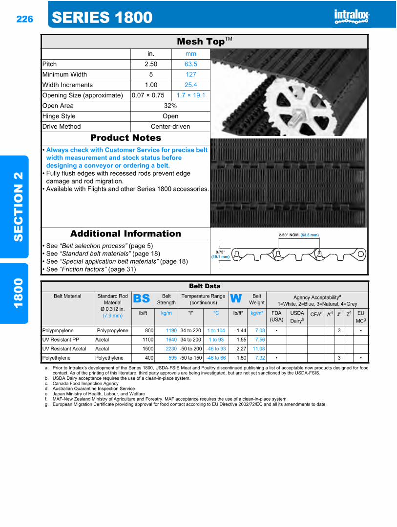
226 SERIES 1800S
EC
TIO
N 2
1800
Mesh TopTM
in. mmPitch 2.50 63.5Minimum Width 5 127Width Increments 1.00 25.4Opening Size (approximate) 0.07 × 0.75 1.7 × 19.1Open Area 32%Hinge Style OpenDrive Method Center-driven
Product Notes• Always check with Customer Service for precise belt
width measurement and stock status before designing a conveyor or ordering a belt.
• Fully flush edges with recessed rods prevent edge damage and rod migration.
• Available with Flights and other Series 1800 accessories.
Additional Information• See “Belt selection process” (page 5)• See “Standard belt materials” (page 18)• See “Special application belt materials” (page 18)• See “Friction factors” (page 31)
Belt DataBelt Material Standard Rod
MaterialØ 0.312 in. (7.9 mm)
BS Belt Strength
Temperature Range (continuous) W Belt
WeightAgency Acceptabilitya
1=White, 2=Blue, 3=Natural, 4=Grey
lb/ft kg/m °F °C lb/ft² kg/m² FDA(USA)
USDADairyb
CFAc Ad Je Zf EUMCg
Polypropylene Polypropylene 800 1190 34 to 220 1 to 104 1.44 7.03 • 3 •
UV Resistant PP Acetal 1100 1640 34 to 200 1 to 93 1.55 7.56
UV Resistant Acetal Acetal 1500 2230 -50 to 200 -46 to 93 2.27 11.08
Polyethylene Polyethylene 400 595 -50 to 150 -46 to 66 1.50 7.32 • 3 •
a. Prior to Intralox’s development of the Series 1800, USDA-FSIS Meat and Poultry discontinued publishing a list of acceptable new products designed for foodcontact. As of the printing of this literature, third party approvals are being investigated, but are not yet sanctioned by the USDA-FSIS.
b. USDA Dairy acceptance requires the use of a clean-in-place system.c. Canada Food Inspection Agencyd. Australian Quarantine Inspection Servicee. Japan Ministry of Health, Labour, and Welfaref. MAF-New Zealand Ministry of Agriculture and Forestry. MAF acceptance requires the use of a clean-in-place system.g. European Migration Certificate providing approval for food contact according to EU Directive 2002/72/EC and all its amendments to date.
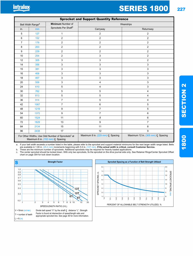
SERIES 1800 227
SE
CT
ION
218
00
Sprocket and Support Quantity ReferenceBelt Width Rangea Minimum Number of
Sprockets Per ShaftbWearstrips
in. mm Carryway Returnway
5 127 1 2 2
6 152 2 2 2
7 178 2 2 2
8 203 2 2 2
9 229 2 2 2
10 254 2 3 2
12 305 3 3 2
14 356 3 3 3
15 381 3 3 3
16 406 3 3 3
18 457 3 3 3
20 508 3 4 3
24 610 5 4 3
30 762 5 5 4
32 813 5 5 4
36 914 7 5 4
42 1067 7 6 5
48 1219 9 7 5
54 1372 9 7 6
60 1524 11 8 6
72 1829 13 9 7
84 2134 15 11 8
96 2438 17 12 9
For Other Widths, Use Odd Number of Sprocketsc at Maximum 6 in. (152 mm) CL Spacing
Maximum 9 in. (229 mm) CL Spacing Maximum 12 in. (305 mm) CL Spacing
a. If your belt width exceeds a number listed in the table, please refer to the sprocket and support material minimums for the next larger width range listed. Beltsare available in 1.00 in. (25.4 mm) increments beginning with 5.0 in. (127 mm). If the actual width is critical, consult Customer Service.
b. These are the minimum number of sprockets. Additional sprockets may be required for heavily loaded applications.c. The center sprocket should be locked down. With only two sprockets, fix the sprocket on the drive journal side only. See Retainer Rings/Center Sprocket Offset
chart on page 304 for lock down location.
S Strength Factor
SPEED/LENGTH RATIO (V/L)
V = ft/min (m/min) Divide belt speed “V” by the shaft CL distance “L”. Strength Factor is found at intersection of speed/length ratio and appropriate sprocket line. See page 36 for more information.T = number of teeth
L = ft (m)
Sprocket Spacing as a Function of Belt Strength Utilized
SPRO
CKET
SPA
CING
, in.
SPROCKET SPACING
, mm
PERCENT OF ALLOWABLE BELT STRENGTH UTILIZED, %
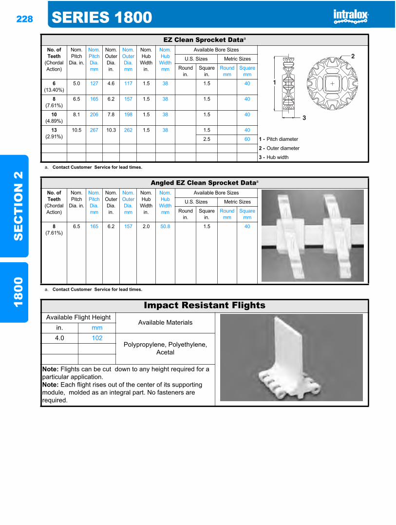
228 SERIES 1800S
EC
TIO
N 2
1800
EZ Clean Sprocket Dataa
No. of Teeth
(Chordal Action)
Nom. Pitch
Dia. in.
Nom. Pitch Dia. mm
Nom. Outer Dia.in.
Nom. Outer Dia.mm
Nom. Hub
Width in.
Nom. Hub
Width mm
Available Bore Sizes
U.S. Sizes Metric Sizes
Round in.
Square in.
Round mm
Square mm
6(13.40%)
5.0 127 4.6 117 1.5 38 1.5 40
8(7.61%)
6.5 165 6.2 157 1.5 38 1.5 40
10(4.89%)
8.1 206 7.8 198 1.5 38 1.5 40
13(2.91%)
10.5 267 10.3 262 1.5 38 1.5 40
2.5 60 1 - Pitch diameter
2 - Outer diameter
3 - Hub width
a. Contact Customer Service for lead times.
Angled EZ Clean Sprocket Dataa
No. of Teeth
(Chordal Action)
Nom. Pitch
Dia. in.
Nom. Pitch Dia. mm
Nom. Outer Dia.in.
Nom. Outer Dia.mm
Nom. Hub
Width in.
Nom. Hub
Width mm
Available Bore Sizes
U.S. Sizes Metric Sizes
Round in.
Square in.
Round mm
Square mm
8(7.61%)
6.5 165 6.2 157 2.0 50.8 1.5 40
a. Contact Customer Service for lead times.
Impact Resistant FlightsAvailable Flight Height
Available Materialsin. mm4.0 102
Polypropylene, Polyethylene, Acetal
Note: Flights can be cut down to any height required for a particular application.Note: Each flight rises out of the center of its supporting module, molded as an integral part. No fasteners are required.
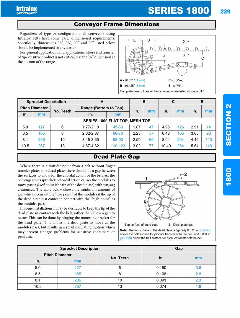
SERIES 1800 229
SE
CT
ION
218
00
Regardless of type or configuration, all conveyors usingIntralox belts have some basic dimensional requirements.Specifically, dimensions “A”, “B”, “C” and “E” listed belowshould be implemented in any design.
For general applications and applications where end transferof tip-sensitive product is not critical, use the “A” dimension atthe bottom of the range.
Where there is a transfer point from a belt without fingertransfer plates to a dead plate, there should be a gap betweenthe surfaces to allow for the chordal action of the belt. As thebelt engages its sprockets, chordal action causes the modules tomove past a fixed point (the tip of the dead plate) with varyingclearances. The table below shows the minimum amount ofgap which occurs at the “low point” of the modules if the tip ofthe dead plate just comes in contact with the “high point” asthe modules pass.
In some installations it may be desirable to keep the tip of thedead plate in contact with the belt, rather than allow a gap tooccur. This can be done by hinging the mounting bracket forthe dead plate. This allows the dead plate to move as themodules pass, but results in a small oscillating motion whichmay present tippage problems for sensitive containers orproducts.
Conveyor Frame Dimensions
A - ±0.031” (1 mm) C - ± (Max)
B - ±0.125” (3 mm) E - ± (Min)
Complete descriptions of the dimensions are listed on page 317.
Sprocket Description A B C EPitch Diameter
No. TeethRange (Bottom to Top)
in. mm in. mm in. mmin. mm in. mm
SERIES 1800 FLAT TOP, MESH TOP5.0 127 6 1.77-2.10 45-53 1.87 47 4.95 126 2.91 746.5 165 8 2.62-2.87 66-73 2.23 57 6.48 165 3.68 938.1 206 10 3.45-3.65 88-93 2.59 66 8.04 204 4.46 11310.5 267 13 4.67-4.82 119-123 3.02 77 10.40 264 5.64 143
Dead Plate Gap
1 - Top surface of dead plate 2 - Dead plate gap
Note: The top surface of the dead plate is typically 0.031 in. (0.8 mm)above the belt surface for product transfer onto the belt, and 0.031 in. (0.8 mm) below the belt surface for product transfer off the belt.
21
Sprocket Description GapPitch Diameter
No. Teeth in. mmin. mm5.0 127 6 0.150 3.86.5 165 8 0.108 2.88.1 206 10 0.091 2.3
10.5 267 13 0.074 1.9

230 SERIES 1800S
EC
TIO
N 2
1800
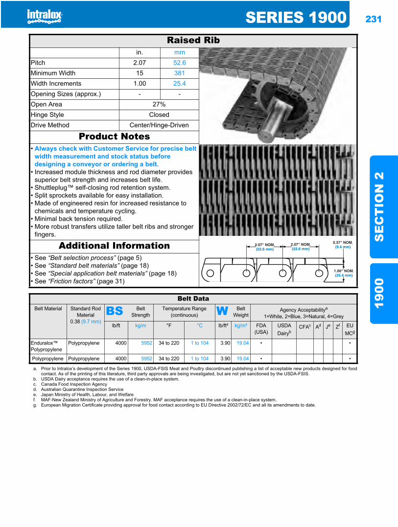
SERIES 1900 231
SE
CT
ION
219
00
Series 19001900
Raised Ribin. mm
Pitch 2.07 52.6Minimum Width 15 381Width Increments 1.00 25.4Opening Sizes (approx.) - -Open Area 27%Hinge Style ClosedDrive Method Center/Hinge-Driven
Product Notes• Always check with Customer Service for precise belt
width measurement and stock status before designing a conveyor or ordering a belt.
• Increased module thickness and rod diameter provides superior belt strength and increases belt life.
• Shuttleplug™ self-closing rod retention system.• Split sprockets available for easy installation.• Made of engineered resin for increased resistance to
chemicals and temperature cycling.• Minimal back tension required.• More robust transfers utilize taller belt ribs and stronger
fingers.
Additional Information• See “Belt selection process” (page 5)• See “Standard belt materials” (page 18)• See “Special application belt materials” (page 18)• See “Friction factors” (page 31)
Belt DataBelt Material Standard Rod
Material0.38 (9.7 mm)
BS Belt Strength
Temperature Range (continuous) W Belt
WeightAgency Acceptabilitya
1=White, 2=Blue, 3=Natural, 4=Grey
lb/ft kg/m °F °C lb/ft² kg/m² FDA(USA)
USDADairyb
CFAc Ad Je Zf EU MCg
Enduralox™ Polypropylene
Polypropylene 4000 5952 34 to 220 1 to 104 3.90 19.04 • •
Polypropylene Polypropylene 4000 5952 34 to 220 1 to 104 3.90 19.04 • •
a. Prior to Intralox’s development of the Series 1900, USDA-FSIS Meat and Poultry discontinued publishing a list of acceptable new products designed for foodcontact. As of the printing of this literature, third party approvals are being investigated, but are not yet sanctioned by the USDA-FSIS.
b. USDA Dairy acceptance requires the use of a clean-in-place system.c. Canada Food Inspection Agencyd. Australian Quarantine Inspection Servicee. Japan Ministry of Health, Labour, and Welfaref. MAF-New Zealand Ministry of Agriculture and Forestry. MAF acceptance requires the use of a clean-in-place system.g. European Migration Certificate providing approval for food contact according to EU Directive 2002/72/EC and all its amendments to date.
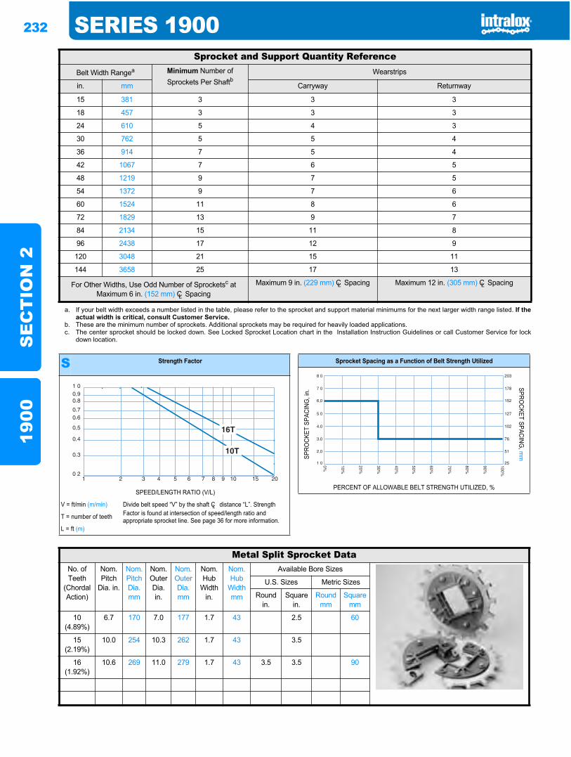
232 SERIES 1900S
EC
TIO
N 2
1900
Sprocket and Support Quantity ReferenceBelt Width Rangea Minimum Number of
Sprockets Per ShaftbWearstrips
in. mm Carryway Returnway
15 381 3 3 3
18 457 3 3 3
24 610 5 4 3
30 762 5 5 4
36 914 7 5 4
42 1067 7 6 5
48 1219 9 7 5
54 1372 9 7 6
60 1524 11 8 6
72 1829 13 9 7
84 2134 15 11 8
96 2438 17 12 9
120 3048 21 15 11
144 3658 25 17 13
For Other Widths, Use Odd Number of Sprocketsc at Maximum 6 in. (152 mm) CL Spacing
Maximum 9 in. (229 mm) CL Spacing Maximum 12 in. (305 mm) CL Spacing
a. If your belt width exceeds a number listed in the table, please refer to the sprocket and support material minimums for the next larger width range listed. If theactual width is critical, consult Customer Service.
b. These are the minimum number of sprockets. Additional sprockets may be required for heavily loaded applications.c. The center sprocket should be locked down. See Locked Sprocket Location chart in the Installation Instruction Guidelines or call Customer Service for lock
down location.
S Strength Factor
SPEED/LENGTH RATIO (V/L)
V = ft/min (m/min) Divide belt speed “V” by the shaft CL distance “L”. Strength Factor is found at intersection of speed/length ratio and appropriate sprocket line. See page 36 for more information.T = number of teeth
L = ft (m)
Sprocket Spacing as a Function of Belt Strength Utilized
SPRO
CKET
SPA
CING
, in.
SPROCKET SPACING
, mm
PERCENT OF ALLOWABLE BELT STRENGTH UTILIZED, %
Metal Split Sprocket DataNo. of Teeth
(Chordal Action)
Nom. Pitch
Dia. in.
Nom. Pitch Dia. mm
Nom. Outer Dia. in.
Nom. Outer Dia.mm
Nom. Hub
Width in.
Nom. Hub
Width mm
Available Bore Sizes
U.S. Sizes Metric Sizes
Round in.
Square in.
Round mm
Square mm
10(4.89%)
6.7 170 7.0 177 1.7 43 2.5 60
15(2.19%)
10.0 254 10.3 262 1.7 43 3.5
16(1.92%)
10.6 269 11.0 279 1.7 43 3.5 3.5 90
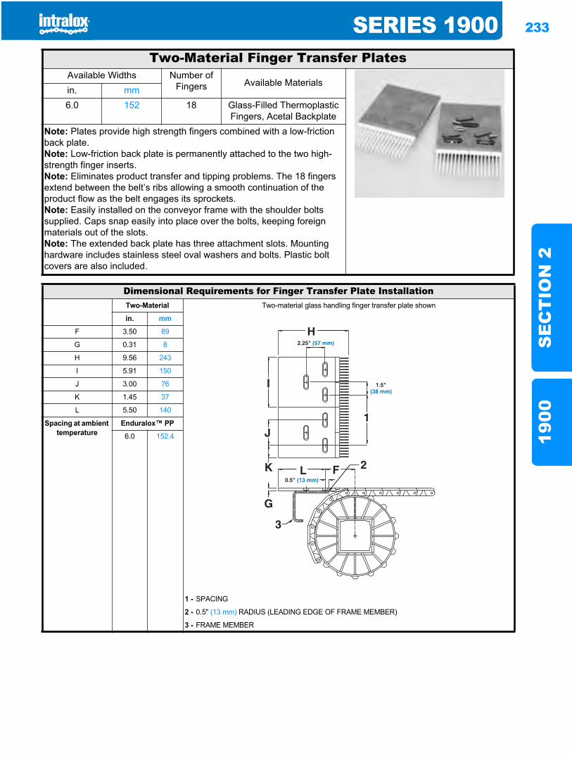
SERIES 1900 233
SE
CT
ION
219
00
Two-Material Finger Transfer PlatesAvailable Widths Number of
Fingers Available Materialsin. mm6.0 152 18 Glass-Filled Thermoplastic
Fingers, Acetal BackplateNote: Plates provide high strength fingers combined with a low-friction back plate.Note: Low-friction back plate is permanently attached to the two high-strength finger inserts.Note: Eliminates product transfer and tipping problems. The 18 fingers extend between the belt’s ribs allowing a smooth continuation of the product flow as the belt engages its sprockets.Note: Easily installed on the conveyor frame with the shoulder bolts supplied. Caps snap easily into place over the bolts, keeping foreign materials out of the slots.Note: The extended back plate has three attachment slots. Mounting hardware includes stainless steel oval washers and bolts. Plastic bolt covers are also included.
Dimensional Requirements for Finger Transfer Plate InstallationTwo-Material Two-material glass handling finger transfer plate shown
in. mm
F 3.50 89
G 0.31 8
H 9.56 243
I 5.91 150
J 3.00 76
K 1.45 37
L 5.50 140
Spacing at ambient temperature
Enduralox™ PP
6.0 152.4
1 - SPACING
2 - 0.5" (13 mm) RADIUS (LEADING EDGE OF FRAME MEMBER)
3 - FRAME MEMBER
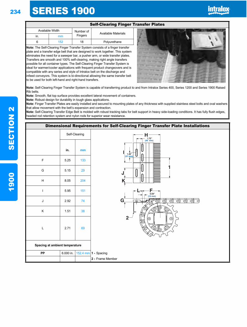
234 SERIES 1900S
EC
TIO
N 2
1900
Self-Clearing Finger Transfer PlatesAvailable Width Number of
Fingers Available Materialsin. mm
6 152 18 Polyurethane
Note: The Self-Clearing Finger Transfer System consists of a finger transfer plate and a transfer edge belt that are designed to work together. This system eliminates the need for a sweeper bar, a pusher arm, or wide transfer plates. Transfers are smooth and 100% self-clearing, making right angle transfers possible for all container types. The Self-Clearing Finger Transfer System is ideal for warmer/cooler applications with frequent product changeovers and is compatible with any series and style of Intralox belt on the discharge and infeed conveyors. This system is bi-directional allowing the same transfer belt to be used for both left-hand and right-hand transfers.
Note: Self-Clearing Finger Transfer System is capable of transferring product to and from Intralox Series 400, Series 1200 and Series 1900 Raised Rib belts.Note: Smooth, flat top surface provides excellent lateral movement of containers.Note: Robust design for durability in tough glass applications.Note: Finger Transfer Plates are easily installed and secured to mounting plates of any thickness with supplied stainless steel bolts and oval washers that allow movement with the belt’s expansion and contraction.Note: Self-Clearing Transfer Edge Belt is molded with robust tracking tabs for belt support in heavy side-loading conditions. It has fully flush edges, headed rod retention system and nylon rods for superior wear resistance.
Dimensional Requirements for Self-Clearing Finger Transfer Plate Installations
Self-Clearing
in. mm
F 5.25 133
G 5.15 29
H 8.05 204
I 5.95 151
J 2.92 74
K 1.51 38
L 2.71 69
Spacing at ambient temperature
PP 6.000 in. 152.4 mm 1 - Spacing
2 - Frame Member
1.75"(45 mm)
0.59"(15 mm)
1.46"(37 mm)
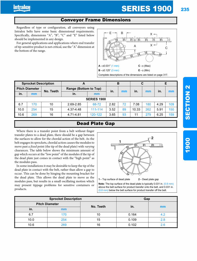
SERIES 1900 235
SE
CT
ION
219
00
Regardless of type or configuration, all conveyors usingIntralox belts have some basic dimensional requirements.Specifically, dimensions “A”, “B”, “C” and “E” listed belowshould be implemented in any design.
For general applications and applications where end transferof tip-sensitive product is not critical, use the “A” dimension atthe bottom of the range.
Where there is a transfer point from a belt without fingertransfer plates to a dead plate, there should be a gap betweenthe surfaces to allow for the chordal action of the belt. As thebelt engages its sprockets, chordal action causes the modules tomove past a fixed point (the tip of the dead plate) with varyingclearances. The table below shows the minimum amount ofgap which occurs at the “low point” of the modules if the tip ofthe dead plate just comes in contact with the “high point” asthe modules pass.
In some installations it may be desirable to keep the tip of thedead plate in contact with the belt, rather than allow a gap tooccur. This can be done by hinging the mounting bracket forthe dead plate. This allows the dead plate to move as themodules pass, but results in a small oscillating motion whichmay present tippage problems for sensitive containers orproducts.
Conveyor Frame Dimensions
A - ±0.031” (1 mm) C - ± (Max)
B - ±0.125” (3 mm) E - ± (Min)
Complete descriptions of the dimensions are listed on page 317.
Sprocket Description A B C EPitch Diameter
No. TeethRange (Bottom to Top)
in. mm in. mm in. mmin. mm in. mm
SERIES 1900 6.7 170 10 2.69-2.85 68-72 2.82 72 7.08 180 4.29 10910.0 254 15 4.37-4.48 111-114 3.52 89 10.33 262 5.91 15010.6 269 16 4.71-4.81 120-122 3.65 93 11 279 6.25 159
Dead Plate Gap
1 - Top surface of dead plate 2 - Dead plate gap
Note: The top surface of the dead plate is typically 0.031 in. (0.8 mm)above the belt surface for product transfer onto the belt, and 0.031 in. (0.8 mm) below the belt surface for product transfer off the belt.
21
Sprocket Description GapPitch Diameter
No. Teeth in. mmin. mm6.7 170 10 0.164 4.2
10.0 254 15 0.109 2.810.6 269 16 0.102 2.6

236 SERIES 1900S
EC
TIO
N 2
1900
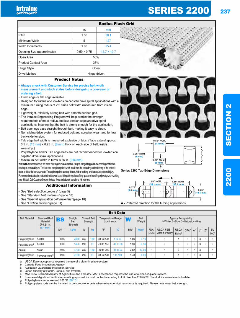
SERIES 2200 237
SE
CT
ION
222
00
Sideflexing belts2200
Radius Flush Gridin. mm
Pitch 1.50 38.1
Minimum Width 5 127
Width Increments 1.00 25.4
Opening Size (approximate) 0.50 × 0.75 12.7 × 19.7
Open Area 50%
Product Contact Area 37%
Hinge Style Open
Drive Method Hinge-driven
Product Notes
Series 2200 Tab Edge Dimensions
• Always check with Customer Service for precise belt width measurement and stock status before designing a conveyor or ordering a belt.
• Flush edge or tab edge available.• Designed for radius and low-tension capstan drive spiral applications with a
minimum turning radius of 2.2 times belt width (measured from inside edge).
• Lightweight, relatively strong belt with smooth surface grid.• The Intralox Engineering Program will help predict the strength
requirements of most radius and low-tension capstan drive spiral applications, insuring that the belt is strong enough for the application.
• Belt openings pass straight through belt, making it easy to clean.• Non sliding drive system for reduced belt and sprocket wear, and for low
back-side tension.• Tab edge belt width is measured exclusive of tabs. (Tabs extend approx.
0.5 in. (13 mm) × 0.25 in. (6 mm) thick on each side of belt, inside wearstrip.)
• Polyethylene and/or Tab edge belts are not recommended for low-tension capstan drive spiral applications.
• Maximum belt width in turns is 36 in. (914 mm)WARNING: Personnel must not place their fingers in or on this belt. Fingers can get trapped in the openings of this belt, resulting in personal injury. This belt also has pinch points which result from the spreading and collapsing of the belt as it flexes to follow the conveyor path. These pinch points can trap fingers, hair or clothing, and can cause personal injury. Personnel should also be instructed not to wear loose fitting clothing, loose fitting gloves or hand/finger jewelry when workingnear this belt. Call Customer Service for tags, flyers and stickers containing this warning.
Additional Information• See “Belt selection process” (page 5)• See “Standard belt materials” (page 18)• See “Special application belt materials” (page 18)• See “Friction factors” (page 31) A - Preferred direction for flat turning applications
Belt DataBelt Material Standard Rod
MaterialØ 0.24 in. (6.1 mm)
BS Straight Belt
Strength
Curved Belt Strength
Temperature Range (continuous) W Belt
WeightAgency Acceptability:
1=White, 2=Blue, 3=Natural, 4=Grey
lb/ft kg/m lb kg °F °C lb/ft² kg/m² FDA (USA)
USDA-FSIS - Meat & Poultry
USDADairya
CFAb Ac Jd Ze EU MCf
Polypropylene Acetal 1600 2380 350 159 34 to 200 1 to 93 1.86 9.10 • • 1 • • 3 • •
Polyethyleneg Acetal 1000 1490 200 91 -50 to 150 -46 to 66 1.96 9.56 • • 3 • • 3 • •
Acetal Nylon 2500 3720 350 159 -50 to 200 -46 to 93 2.82 13.80 • • 3 • • 3 •
Polypropylene Polypropyleneh 1400 2100 200 91 34 to 220 1 to 104 1.78 8.69 • • 1 • • 3 •
a. USDA Dairy acceptance requires the use of a clean-in-place-system.b. Canada Food Inspection Agencyc. Australian Quarantine Inspection Serviced. Japan Ministry of Health, Labour, and Welfaree. MAF-New Zealand Ministry of Agriculture and Forestry. MAF acceptance requires the use of a clean-in-place system.f. European Migration Certificate providing approval for food contact according to EU Directive 2002/72/EC and all its amendments to date.g. Polyethylene cannot exceed 150 °F (66 °C)h. Polypropylene rods can be installed in polypropylene belts when extra chemical resistance is required. Please note lower belt strength.
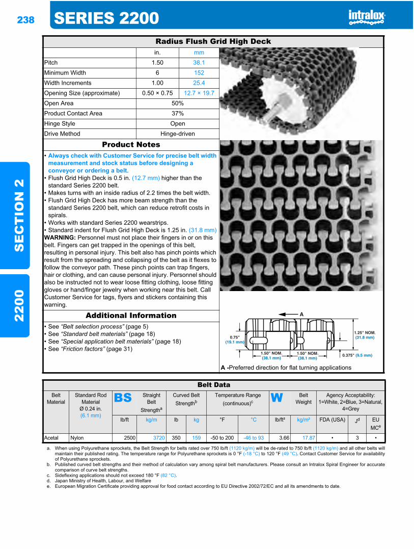
238 SERIES 2200S
EC
TIO
N 2
2200
Radius Flush Grid High Deckin. mm
Pitch 1.50 38.1
Minimum Width 6 152
Width Increments 1.00 25.4
Opening Size (approximate) 0.50 × 0.75 12.7 × 19.7
Open Area 50%
Product Contact Area 37%
Hinge Style Open
Drive Method Hinge-driven
Product Notes• Always check with Customer Service for precise belt width
measurement and stock status before designing a conveyor or ordering a belt.
• Flush Grid High Deck is 0.5 in. (12.7 mm) higher than the standard Series 2200 belt.
• Makes turns with an inside radius of 2.2 times the belt width.• Flush Grid High Deck has more beam strength than the
standard Series 2200 belt, which can reduce retrofit costs in spirals.
• Works with standard Series 2200 wearstrips.• Standard indent for Flush Grid High Deck is 1.25 in. (31.8 mm)WARNING: Personnel must not place their fingers in or on this belt. Fingers can get trapped in the openings of this belt, resulting in personal injury. This belt also has pinch points which result from the spreading and collapsing of the belt as it flexes to follow the conveyor path. These pinch points can trap fingers, hair or clothing, and can cause personal injury. Personnel should also be instructed not to wear loose fitting clothing, loose fitting gloves or hand/finger jewelry when working near this belt. Call Customer Service for tags, flyers and stickers containing this warning.
Additional Information• See “Belt selection process” (page 5)• See “Standard belt materials” (page 18)• See “Special application belt materials” (page 18)• See “Friction factors” (page 31)
A -Preferred direction for flat turning applications
Belt DataBelt
MaterialStandard Rod
MaterialØ 0.24 in. (6.1 mm)
BS Straight Belt
Strengtha
Curved Belt Strengthb
Temperature Range (continuous)c W Belt
WeightAgency Acceptability:
1=White, 2=Blue, 3=Natural, 4=Grey
lb/ft kg/m lb kg °F °C lb/ft² kg/m² FDA (USA) Jd EU MCe
Acetal Nylon 2500 3720 350 159 -50 to 200 -46 to 93 3.66 17.87 • 3 •
a. When using Polyurethane sprockets, the Belt Strength for belts rated over 750 lb/ft (1120 kg/m) will be de-rated to 750 lb/ft (1120 kg/m) and all other belts willmaintain their published rating. The temperature range for Polyurethane sprockets is 0 °F (-18 °C) to 120 °F (49 °C). Contact Customer Service for availabilityof Polyurethane sprockets.
b. Published curved belt strengths and their method of calculation vary among spiral belt manufacturers. Please consult an Intralox Spiral Engineer for accuratecomparison of curve belt strengths.
c. Sideflexing applications should not exceed 180 °F (82 °C).d. Japan Ministry of Health, Labour, and Welfaree. European Migration Certificate providing approval for food contact according to EU Directive 2002/72/EC and all its amendments to date.
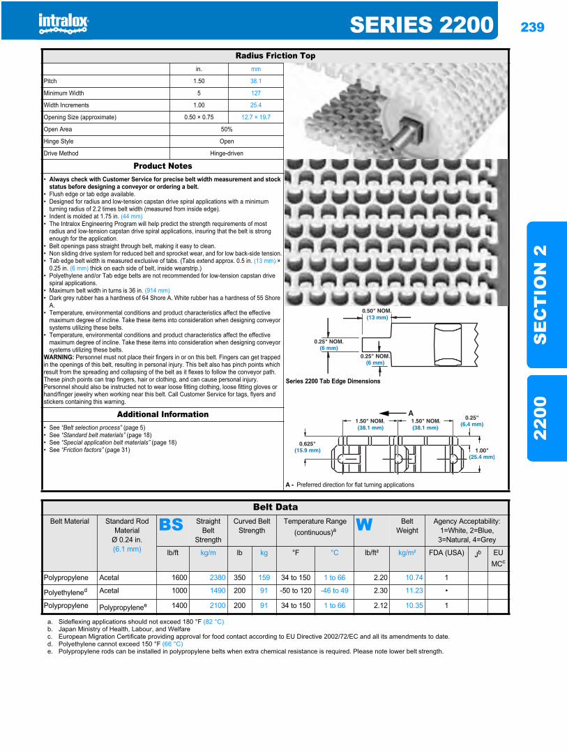
SERIES 2200 239
SE
CT
ION
222
00
Radius Friction Topin. mm
Pitch 1.50 38.1
Minimum Width 5 127
Width Increments 1.00 25.4
Opening Size (approximate) 0.50 × 0.75 12.7 × 19.7
Open Area 50%
Hinge Style Open
Drive Method Hinge-driven
Product Notes
Series 2200 Tab Edge Dimensions
• Always check with Customer Service for precise belt width measurement and stock status before designing a conveyor or ordering a belt.
• Flush edge or tab edge available.• Designed for radius and low-tension capstan drive spiral applications with a minimum
turning radius of 2.2 times belt width (measured from inside edge).• Indent is molded at 1.75 in. (44 mm)• The Intralox Engineering Program will help predict the strength requirements of most
radius and low-tension capstan drive spiral applications, insuring that the belt is strong enough for the application.
• Belt openings pass straight through belt, making it easy to clean.• Non sliding drive system for reduced belt and sprocket wear, and for low back-side tension.• Tab edge belt width is measured exclusive of tabs. (Tabs extend approx. 0.5 in. (13 mm) ×
0.25 in. (6 mm) thick on each side of belt, inside wearstrip.)• Polyethylene and/or Tab edge belts are not recommended for low-tension capstan drive
spiral applications.• Maximum belt width in turns is 36 in. (914 mm)• Dark grey rubber has a hardness of 64 Shore A. White rubber has a hardness of 55 Shore
A.• Temperature, environmental conditions and product characteristics affect the effective
maximum degree of incline. Take these items into consideration when designing conveyor systems utilizing these belts.
• Temperature, environmental conditions and product characteristics affect the effective maximum degree of incline. Take these items into consideration when designing conveyor systems utilizing these belts.
WARNING: Personnel must not place their fingers in or on this belt. Fingers can get trapped in the openings of this belt, resulting in personal injury. This belt also has pinch points which result from the spreading and collapsing of the belt as it flexes to follow the conveyor path. These pinch points can trap fingers, hair or clothing, and can cause personal injury. Personnel should also be instructed not to wear loose fitting clothing, loose fitting gloves or hand/finger jewelry when working near this belt. Call Customer Service for tags, flyers and stickers containing this warning.
Additional Information• See “Belt selection process” (page 5)• See “Standard belt materials” (page 18)• See “Special application belt materials” (page 18)• See “Friction factors” (page 31)
A - Preferred direction for flat turning applications
Belt DataBelt Material Standard Rod
MaterialØ 0.24 in. (6.1 mm)
BS Straight Belt
Strength
Curved Belt Strength
Temperature Range (continuous)a W Belt
WeightAgency Acceptability:
1=White, 2=Blue, 3=Natural, 4=Grey
lb/ft kg/m lb kg °F °C lb/ft² kg/m² FDA (USA) Jb EU MCc
Polypropylene Acetal 1600 2380 350 159 34 to 150 1 to 66 2.20 10.74 1
Polyethylened Acetal 1000 1490 200 91 -50 to 120 -46 to 49 2.30 11.23 •
Polypropylene Polypropylenee 1400 2100 200 91 34 to 150 1 to 66 2.12 10.35 1
a. Sideflexing applications should not exceed 180 °F (82 °C)b. Japan Ministry of Health, Labour, and Welfarec. European Migration Certificate providing approval for food contact according to EU Directive 2002/72/EC and all its amendments to date.d. Polyethylene cannot exceed 150 °F (66 °C)e. Polypropylene rods can be installed in polypropylene belts when extra chemical resistance is required. Please note lower belt strength.
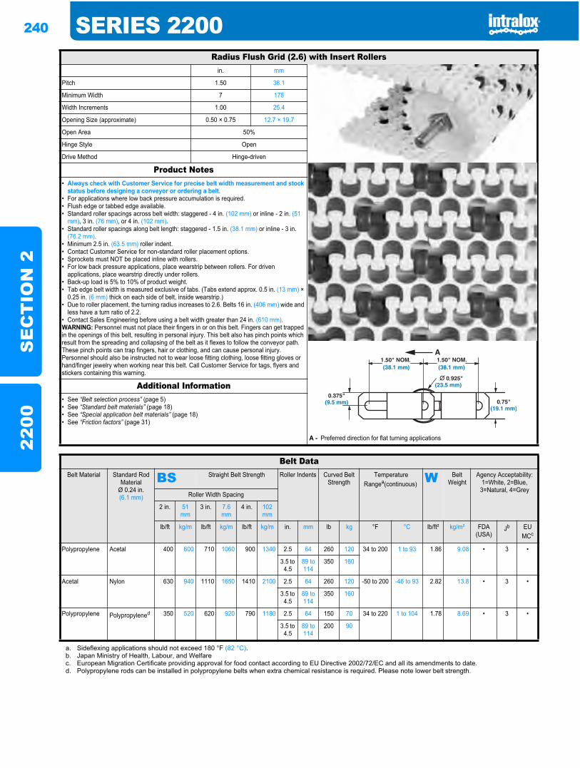
240 SERIES 2200S
EC
TIO
N 2
2200
Radius Flush Grid (2.6) with Insert Rollersin. mm
Pitch 1.50 38.1
Minimum Width 7 178
Width Increments 1.00 25.4
Opening Size (approximate) 0.50 × 0.75 12.7 × 19.7
Open Area 50%
Hinge Style Open
Drive Method Hinge-driven
Product Notes• Always check with Customer Service for precise belt width measurement and stock
status before designing a conveyor or ordering a belt.• For applications where low back pressure accumulation is required.• Flush edge or tabbed edge available.• Standard roller spacings across belt width: staggered - 4 in. (102 mm) or inline - 2 in. (51
mm), 3 in. (76 mm), or 4 in. (102 mm).• Standard roller spacings along belt length: staggered - 1.5 in. (38.1 mm) or inline - 3 in.
(76.2 mm).• Minimum 2.5 in. (63.5 mm) roller indent.• Contact Customer Service for non-standard roller placement options.• Sprockets must NOT be placed inline with rollers.• For low back pressure applications, place wearstrip between rollers. For driven
applications, place wearstrip directly under rollers.• Back-up load is 5% to 10% of product weight.• Tab edge belt width is measured exclusive of tabs. (Tabs extend approx. 0.5 in. (13 mm) ×
0.25 in. (6 mm) thick on each side of belt, inside wearstrip.)• Due to roller placement, the turning radius increases to 2.6. Belts 16 in. (406 mm) wide and
less have a turn ratio of 2.2.• Contact Sales Engineering before using a belt width greater than 24 in. (610 mm).WARNING: Personnel must not place their fingers in or on this belt. Fingers can get trapped in the openings of this belt, resulting in personal injury. This belt also has pinch points which result from the spreading and collapsing of the belt as it flexes to follow the conveyor path. These pinch points can trap fingers, hair or clothing, and can cause personal injury. Personnel should also be instructed not to wear loose fitting clothing, loose fitting gloves or hand/finger jewelry when working near this belt. Call Customer Service for tags, flyers and stickers containing this warning.
Additional Information• See “Belt selection process” (page 5)• See “Standard belt materials” (page 18)• See “Special application belt materials” (page 18)• See “Friction factors” (page 31)
A - Preferred direction for flat turning applications
Belt DataBelt Material Standard Rod
MaterialØ 0.24 in. (6.1 mm)
BS Straight Belt Strength Roller Indents Curved Belt Strength
Temperature Rangea(continuous) W Belt
WeightAgency Acceptability:
1=White, 2=Blue, 3=Natural, 4=Grey
Roller Width Spacing
2 in. 51 mm
3 in. 7.6mm
4 in. 102 mm
lb/ft kg/m lb/ft kg/m lb/ft kg/m in. mm lb kg °F °C lb/ft² kg/m² FDA (USA)
Jb EUMCc
Polypropylene Acetal 400 600 710 1060 900 1340 2.5 64 260 120 34 to 200 1 to 93 1.86 9.08 • 3 •
3.5 to 4.5
89 to 114
350 160
Acetal Nylon 630 940 1110 1650 1410 2100 2.5 64 260 120 -50 to 200 -46 to 93 2.82 13.8 • 3 •
3.5 to 4.5
89 to 114
350 160
Polypropylene Polypropylened 350 520 620 920 790 1180 2.5 64 150 70 34 to 220 1 to 104 1.78 8.69 • 3 •
3.5 to 4.5
89 to 114
200 90
a. Sideflexing applications should not exceed 180 °F (82 °C).b. Japan Ministry of Health, Labour, and Welfarec. European Migration Certificate providing approval for food contact according to EU Directive 2002/72/EC and all its amendments to date.d. Polypropylene rods can be installed in polypropylene belts when extra chemical resistance is required. Please note lower belt strength.
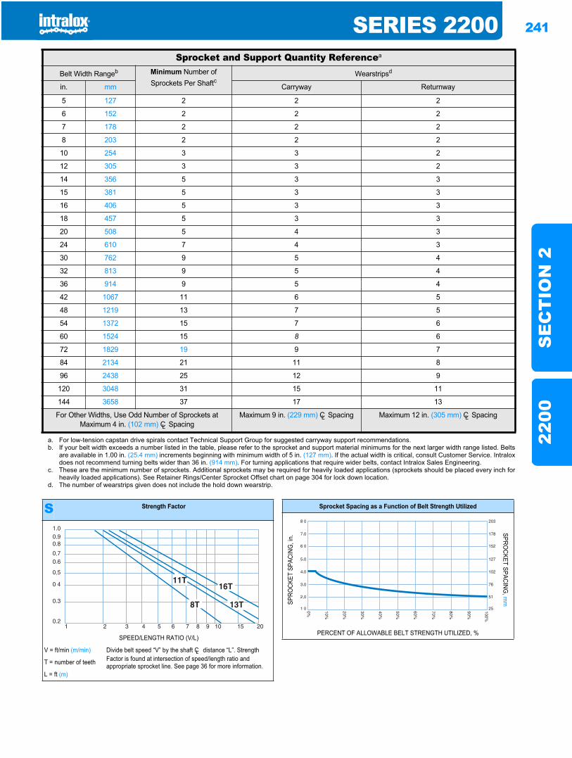
SERIES 2200 241
SE
CT
ION
222
00
Sprocket and Support Quantity Referencea
Belt Width Rangeb Minimum Number of Sprockets Per Shaftc
Wearstripsd
in. mm Carryway Returnway
5 127 2 2 2
6 152 2 2 2
7 178 2 2 2
8 203 2 2 2
10 254 3 3 2
12 305 3 3 2
14 356 5 3 3
15 381 5 3 3
16 406 5 3 3
18 457 5 3 3
20 508 5 4 3
24 610 7 4 3
30 762 9 5 4
32 813 9 5 4
36 914 9 5 4
42 1067 11 6 5
48 1219 13 7 5
54 1372 15 7 6
60 1524 15 8 6
72 1829 19 9 7
84 2134 21 11 8
96 2438 25 12 9
120 3048 31 15 11
144 3658 37 17 13
For Other Widths, Use Odd Number of Sprockets at Maximum 4 in. (102 mm) CL Spacing
Maximum 9 in. (229 mm) CL Spacing Maximum 12 in. (305 mm) CL Spacing
a. For low-tension capstan drive spirals contact Technical Support Group for suggested carryway support recommendations.b. If your belt width exceeds a number listed in the table, please refer to the sprocket and support material minimums for the next larger width range listed. Belts
are available in 1.00 in. (25.4 mm) increments beginning with minimum width of 5 in. (127 mm). If the actual width is critical, consult Customer Service. Intraloxdoes not recommend turning belts wider than 36 in. (914 mm). For turning applications that require wider belts, contact Intralox Sales Engineering.
c. These are the minimum number of sprockets. Additional sprockets may be required for heavily loaded applications (sprockets should be placed every inch forheavily loaded applications). See Retainer Rings/Center Sprocket Offset chart on page 304 for lock down location.
d. The number of wearstrips given does not include the hold down wearstrip.
S Strength Factor
SPEED/LENGTH RATIO (V/L)
V = ft/min (m/min) Divide belt speed “V” by the shaft CL distance “L”. Strength Factor is found at intersection of speed/length ratio and appropriate sprocket line. See page 36 for more information.T = number of teeth
L = ft (m)
Sprocket Spacing as a Function of Belt Strength Utilized
SPRO
CKET
SPA
CING
, in.
SPROCKET SPACING
, mm
PERCENT OF ALLOWABLE BELT STRENGTH UTILIZED, %
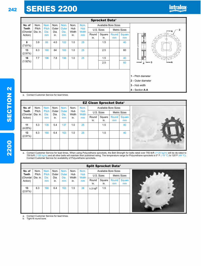
242 SERIES 2200S
EC
TIO
N 2
2200
Sprocket Dataa
No. of Teeth
(Chordal Action)
Nom. Pitch
Dia. in.
Nom. Pitch Dia. mm
Nom. Outer Dia.in.
Nom. Outer Dia.mm
Nom. Hub
Width in.
Nom. Hub
Width mm
Available Bore Sizes
U.S. Sizes Metric Sizes
Round in.
Square in.
Round mm
Square mm
8(7.61%)
3.9 99 4.0 102 1.0 25 1.5 40
13(2.91%)
6.3 160 64 163 1.0 25 2.5 60
16(1.92%)
7.7 196 7.8 198 1.0 25 1.5 40
2.5 60
1 - Pitch diameter
2 - Outer diameter
3 - Hub width
4 - Section A-A
a. Contact Customer Service for lead times.
EZ Clean Sprocket Dataa
No. of Teeth
(Chordal Action)
Nom. Pitch
Dia. in.
Nom. Pitch Dia. mm
Nom. Outer Dia.in.
Nom. Outer Dia.mm
Nom. Hub
Width in.
Nom. Hub
Width mm
Available Bore Sizes
U.S. Sizes Metric Sizes
Round in.
Square in.
Round mm
Square mm
11(4.05%)
5.3 135 5.4 137 1.0 25 1.5 40
13(2.91%)
6.3 160 6.4 163 1.0 25 1.5 40
a. Contact Customer Service for lead times. When using Polyurethane sprockets, the Belt Strength for belts rated over 750 lb/ft (1120 kg/m) will be de-rated to750 lb/ft (1120 kg/m) and all other belts will maintain their published rating. The temperature range for Polyurethane sprockets is 0° F (-18 °C) to 120°F (49 °C).Contact Customer Service for availability of Polyurethane sprockets.
Split Sprocket Dataa
No. of Teeth
(Chordal Action)
Nom. Pitch
Dia. in.
Nom. Pitch Dia. mm
Nom. Outer Dia.in.
Nom. Outer Dia.mm
Nom. Hub
Width in.
Nom. Hub
Width mm
Available Bore Sizes
U.S. Sizes Metric Sizes
Round in.
Square in.
Round mm
Square mm
13(2.91%)
6.3 160 6.4 163 1.5 38 1-7/16b 1.5
a. Contact Customer Service for lead times.b. Tight fit round bore.
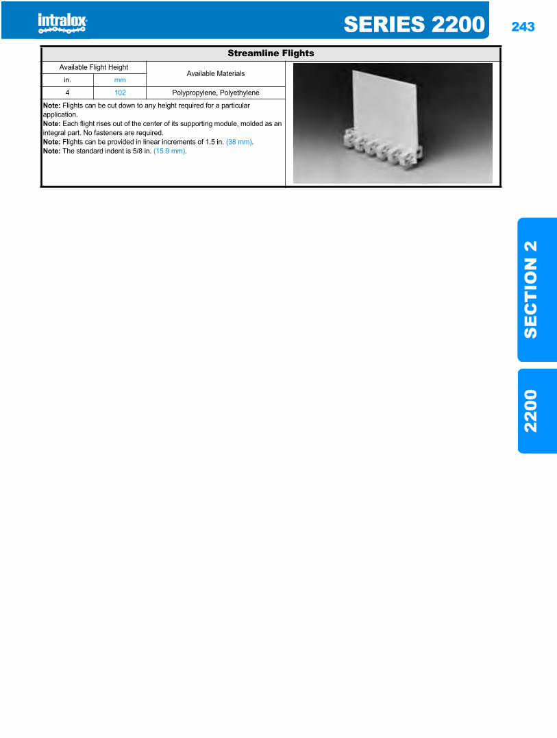
SERIES 2200 243
SE
CT
ION
222
00
Streamline FlightsAvailable Flight Height
Available Materialsin. mm
4 102 Polypropylene, Polyethylene
Note: Flights can be cut down to any height required for a particular application.Note: Each flight rises out of the center of its supporting module, molded as an integral part. No fasteners are required.Note: Flights can be provided in linear increments of 1.5 in. (38 mm).Note: The standard indent is 5/8 in. (15.9 mm).
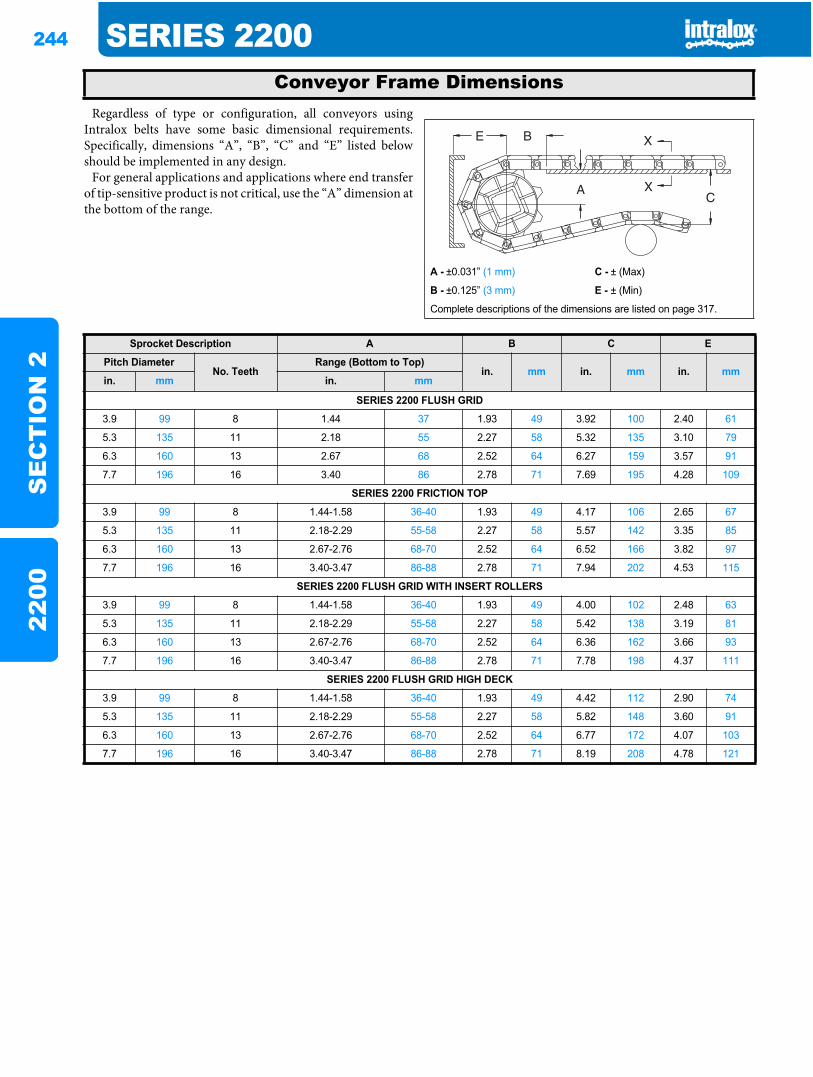
244 SERIES 2200S
EC
TIO
N 2
2200
Regardless of type or configuration, all conveyors usingIntralox belts have some basic dimensional requirements.Specifically, dimensions “A”, “B”, “C” and “E” listed belowshould be implemented in any design.
For general applications and applications where end transferof tip-sensitive product is not critical, use the “A” dimension atthe bottom of the range.
Conveyor Frame Dimensions
A - ±0.031” (1 mm) C - ± (Max)
B - ±0.125” (3 mm) E - ± (Min)
Complete descriptions of the dimensions are listed on page 317.
Sprocket Description A B C E
Pitch DiameterNo. Teeth
Range (Bottom to Top)in. mm in. mm in. mm
in. mm in. mm
SERIES 2200 FLUSH GRID
3.9 99 8 1.44 37 1.93 49 3.92 100 2.40 61
5.3 135 11 2.18 55 2.27 58 5.32 135 3.10 79
6.3 160 13 2.67 68 2.52 64 6.27 159 3.57 91
7.7 196 16 3.40 86 2.78 71 7.69 195 4.28 109
SERIES 2200 FRICTION TOP
3.9 99 8 1.44-1.58 36-40 1.93 49 4.17 106 2.65 67
5.3 135 11 2.18-2.29 55-58 2.27 58 5.57 142 3.35 85
6.3 160 13 2.67-2.76 68-70 2.52 64 6.52 166 3.82 97
7.7 196 16 3.40-3.47 86-88 2.78 71 7.94 202 4.53 115
SERIES 2200 FLUSH GRID WITH INSERT ROLLERS
3.9 99 8 1.44-1.58 36-40 1.93 49 4.00 102 2.48 63
5.3 135 11 2.18-2.29 55-58 2.27 58 5.42 138 3.19 81
6.3 160 13 2.67-2.76 68-70 2.52 64 6.36 162 3.66 93
7.7 196 16 3.40-3.47 86-88 2.78 71 7.78 198 4.37 111
SERIES 2200 FLUSH GRID HIGH DECK
3.9 99 8 1.44-1.58 36-40 1.93 49 4.42 112 2.90 74
5.3 135 11 2.18-2.29 55-58 2.27 58 5.82 148 3.60 91
6.3 160 13 2.67-2.76 68-70 2.52 64 6.77 172 4.07 103
7.7 196 16 3.40-3.47 86-88 2.78 71 8.19 208 4.78 121
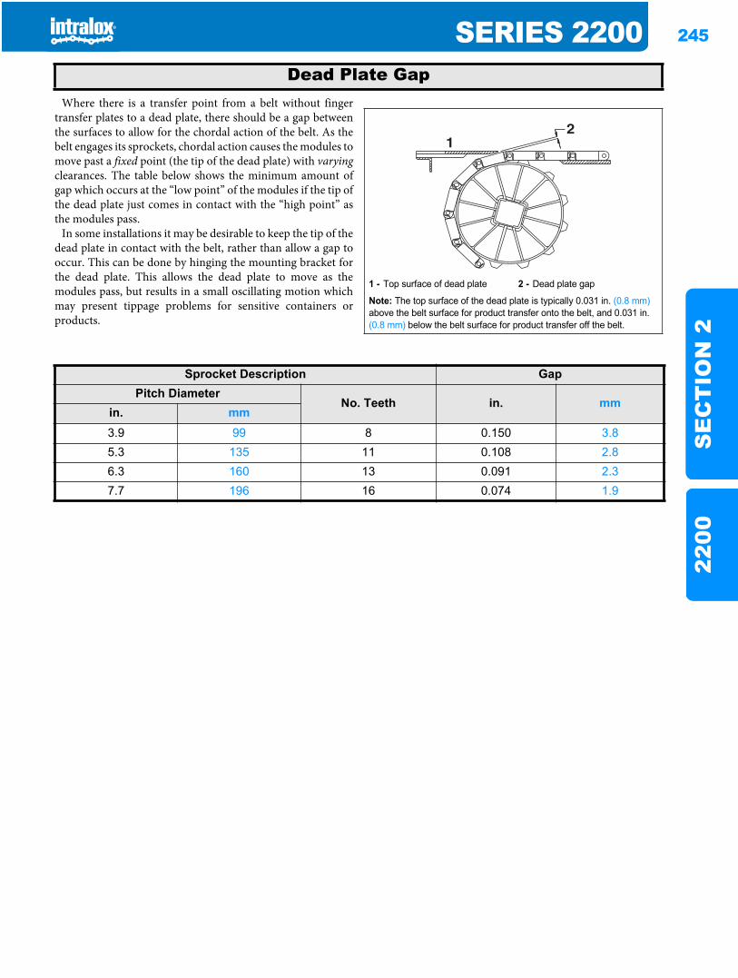
SERIES 2200 245
SE
CT
ION
222
00
Where there is a transfer point from a belt without fingertransfer plates to a dead plate, there should be a gap betweenthe surfaces to allow for the chordal action of the belt. As thebelt engages its sprockets, chordal action causes the modules tomove past a fixed point (the tip of the dead plate) with varyingclearances. The table below shows the minimum amount ofgap which occurs at the “low point” of the modules if the tip ofthe dead plate just comes in contact with the “high point” asthe modules pass.
In some installations it may be desirable to keep the tip of thedead plate in contact with the belt, rather than allow a gap tooccur. This can be done by hinging the mounting bracket forthe dead plate. This allows the dead plate to move as themodules pass, but results in a small oscillating motion whichmay present tippage problems for sensitive containers orproducts.
Dead Plate Gap
1 - Top surface of dead plate 2 - Dead plate gap
Note: The top surface of the dead plate is typically 0.031 in. (0.8 mm)above the belt surface for product transfer onto the belt, and 0.031 in. (0.8 mm) below the belt surface for product transfer off the belt.
21
Sprocket Description GapPitch Diameter
No. Teeth in. mmin. mm3.9 99 8 0.150 3.85.3 135 11 0.108 2.86.3 160 13 0.091 2.37.7 196 16 0.074 1.9
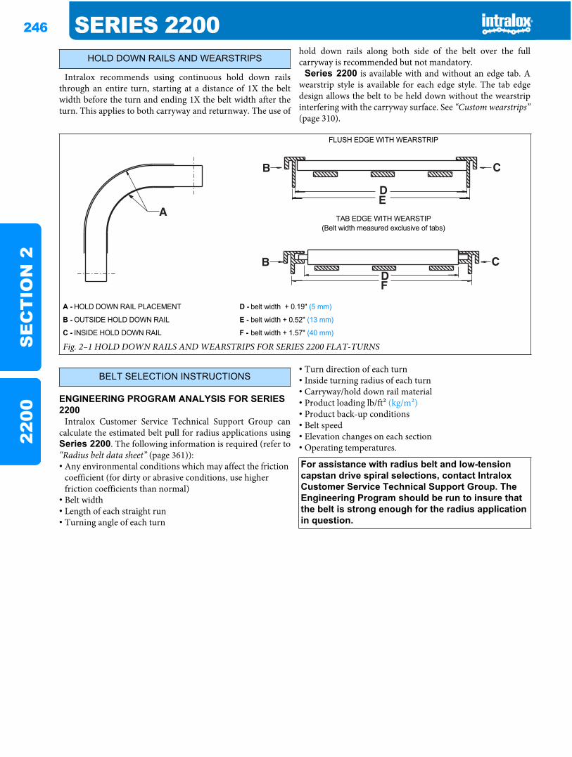
246 SERIES 2200S
EC
TIO
N 2
2200
Intralox recommends using continuous hold down railsthrough an entire turn, starting at a distance of 1X the beltwidth before the turn and ending 1X the belt width after theturn. This applies to both carryway and returnway. The use of
hold down rails along both side of the belt over the fullcarryway is recommended but not mandatory.
Series 2200 is available with and without an edge tab. Awearstrip style is available for each edge style. The tab edgedesign allows the belt to be held down without the wearstripinterfering with the carryway surface. See “Custom wearstrips”(page 310).
ENGINEERING PROGRAM ANALYSIS FOR SERIES 2200
Intralox Customer Service Technical Support Group cancalculate the estimated belt pull for radius applications usingSeries 2200. The following information is required (refer to“Radius belt data sheet” (page 361)):• Any environmental conditions which may affect the friction
coefficient (for dirty or abrasive conditions, use higher friction coefficients than normal)
• Belt width• Length of each straight run• Turning angle of each turn
• Turn direction of each turn• Inside turning radius of each turn• Carryway/hold down rail material• Product loading lb/ft2 (kg/m2)• Product back-up conditions• Belt speed• Elevation changes on each section• Operating temperatures.
HOLD DOWN RAILS AND WEARSTRIPS
FLUSH EDGE WITH WEARSTRIP
TAB EDGE WITH WEARSTIP(Belt width measured exclusive of tabs)
A - HOLD DOWN RAIL PLACEMENT D - belt width + 0.19" (5 mm)
B - OUTSIDE HOLD DOWN RAIL E - belt width + 0.52" (13 mm)
C - INSIDE HOLD DOWN RAIL F - belt width + 1.57" (40 mm)
Fig. 2–1 HOLD DOWN RAILS AND WEARSTRIPS FOR SERIES 2200 FLAT-TURNS
BELT SELECTION INSTRUCTIONS
For assistance with radius belt and low-tension capstan drive spiral selections, contact Intralox Customer Service Technical Support Group. The Engineering Program should be run to insure that the belt is strong enough for the radius application in question.
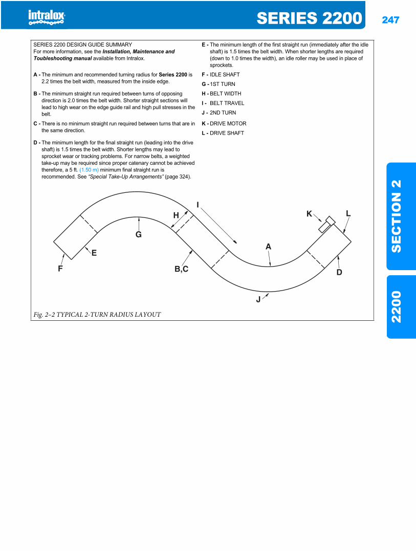
SERIES 2200 247
SE
CT
ION
222
00
SERIES 2200 DESIGN GUIDE SUMMARYFor more information, see the Installation, Maintenance and Toubleshooting manual available from Intralox.
E - The minimum length of the first straight run (immediately after the idle shaft) is 1.5 times the belt width. When shorter lengths are required (down to 1.0 times the width), an idle roller may be used in place of sprockets.
A - The minimum and recommended turning radius for Series 2200 is 2.2 times the belt width, measured from the inside edge.
F - IDLE SHAFT
G - 1ST TURN
B - The minimum straight run required between turns of opposing direction is 2.0 times the belt width. Shorter straight sections will lead to high wear on the edge guide rail and high pull stresses in the belt.
H - BELT WIDTH
I - BELT TRAVEL
J - 2ND TURN
C - There is no minimum straight run required between turns that are in the same direction.
K - DRIVE MOTOR
L - DRIVE SHAFT
D - The minimum length for the final straight run (leading into the drive shaft) is 1.5 times the belt width. Shorter lengths may lead to sprocket wear or tracking problems. For narrow belts, a weighted take-up may be required since proper catenary cannot be achieved therefore, a 5 ft. (1.50 m) minimum final straight run is recommended. See “Special Take-Up Arrangements” (page 324).
Fig. 2–2 TYPICAL 2-TURN RADIUS LAYOUT

248 SERIES 2200S
EC
TIO
N 2
2200
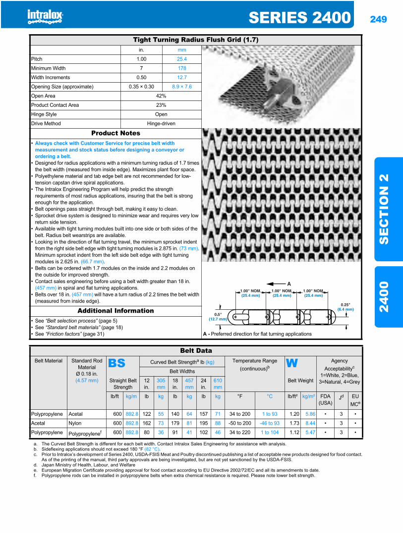
SERIES 2400 249
SE
CT
ION
224
00
Series 24002400
Tight Turning Radius Flush Grid (1.7)in. mm
Pitch 1.00 25.4
Minimum Width 7 178
Width Increments 0.50 12.7
Opening Size (approximate) 0.35 × 0.30 8.9 × 7.6
Open Area 42%
Product Contact Area 23%
Hinge Style Open
Drive Method Hinge-driven
Product Notes• Always check with Customer Service for precise belt width
measurement and stock status before designing a conveyor or ordering a belt.
• Designed for radius applications with a minimum turning radius of 1.7 times the belt width (measured from inside edge). Maximizes plant floor space.
• Polyethylene material and tab edge belt are not recommended for low-tension capstan drive spiral applications.
• The Intralox Engineering Program will help predict the strength requirements of most radius applications, insuring that the belt is strong enough for the application.
• Belt openings pass straight through belt, making it easy to clean.• Sprocket drive system is designed to minimize wear and requires very low
return side tension.• Available with tight turning modules built into one side or both sides of the
belt. Radius belt wearstrips are available.• Looking in the direction of flat turning travel, the minimum sprocket indent
from the right side belt edge with tight turning modules is 2.875 in. (73 mm).Minimum sprocket indent from the left side belt edge with tight turning modules is 2.625 in. (66.7 mm).
• Belts can be ordered with 1.7 modules on the inside and 2.2 modules on the outside for improved strength.
• Contact sales engineering before using a belt width greater than 18 in. (457 mm) in spiral and flat turning applications.
• Belts over 18 in. (457 mm) will have a turn radius of 2.2 times the belt width (measured from inside edge).
Additional Information• See “Belt selection process” (page 5)• See “Standard belt materials” (page 18)• See “Friction factors” (page 31) A - Preferred direction for flat turning applications
Belt DataBelt Material Standard Rod
MaterialØ 0.18 in. (4.57 mm)
BS Curved Belt Strengtha lb (kg) Temperature Range (continuous)b W Agency
Acceptabilityc
1=White, 2=Blue, 3=Natural, 4=Grey
Belt Widths
Straight Belt Strength
12in.
305 mm
18in.
457 mm
24in.
610 mm
Belt Weight
lb/ft kg/m lb kg lb kg lb kg °F °C lb/ft² kg/m² FDA(USA)
Jd EUMCe
Polypropylene Acetal 600 892.8 122 55 140 64 157 71 34 to 200 1 to 93 1.20 5.86 • 3 •
Acetal Nylon 600 892.8 162 73 179 81 195 88 -50 to 200 -46 to 93 1.73 8.44 • 3 •
Polypropylene Polypropylenef 600 892.8 80 36 91 41 102 46 34 to 220 1 to 104 1.12 5.47 • 3 •
a. The Curved Belt Strength is different for each belt width. Contact Intralox Sales Engineering for assistance with analysis.b. Sideflexing applications should not exceed 180 °F (82 °C).c. Prior to Intralox’s development of Series 2400, USDA-FSIS Meat and Poultry discontinued publishing a list of acceptable new products designed for food contact.
As of the printing of the manual, third party approvals are being investigated, but are not yet sanctioned by the USDA-FSIS.d. Japan Ministry of Health, Labour, and Welfaree. European Migration Certificate providing approval for food contact according to EU Directive 2002/72/EC and all its amendments to date.f. Polypropylene rods can be installed in polypropylene belts when extra chemical resistance is required. Please note lower belt strength.
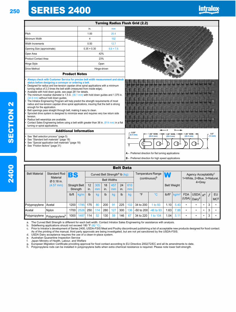
250 SERIES 2400S
EC
TIO
N 2
2400
Turning Radius Flush Grid (2.2)in. mm
Pitch 1.00 25.4
Minimum Width 4 102
Width Increments 0.50 12.7
Opening Size (approximate) 0.35 × 0.30 8.9 × 7.6
Open Area 42%
Product Contact Area 23%
Hinge Style Open
Drive Method Hinge-driven
Product Notes• Always check with Customer Service for precise belt width measurement and stock
status before designing a conveyor or ordering a belt.• Designed for radius and low-tension capstan drive spiral applications with a minimum
turning radius of 2.2 times the belt width (measured from inside edge).• Available with hold down guide, see page 261 for details.• The minimum nosebar diameter is 1.5 in. (38.1 mm) with hold down guides and 1.375 in.
(34.9 mm) without hold down guides.• The Intralox Engineering Program will help predict the strength requirements of most
radius and low-tension capstan drive spiral applications, insuring that the belt is strong enough for the application.
• Belt openings pass straight through belt, making it easy to clean.• Sprocket drive system is designed to minimize wear and requires very low return side
tension.• Radius belt wearstrips are available.• Contact Sales Engineering before using a belt width greater than 36 in. (914 mm) in a flat
turning or spiral applications.
Additional Information• See “Belt selection process” (page 5)• See “Standard belt materials” (page 18)• See “Special application belt materials” (page 18)• See “Friction factors” (page 31)
A - Preferred direction for flat turning applications
B - Preferred direction for high speed applications
Belt DataBelt Material Standard Rod
MaterialØ 0.18 in. (4.57 mm)
BS Curved Belt Strengtha lb (kg) Temperature Range (continuous)b W Agency Acceptabilityc
1=White, 2=Blue, 3=Natural, 4=Grey
Belt Widths
Straight Belt Strength
12in.
305 mm
18 in.
457 mm
24in.
610mm
Belt Weight
lb/ft kg/m lb kg lb kg lb kg °F °C lb/ft² kg/m² FDA(USA)
USDADairyd
Ae Jf EU MCg
Polypropylene Acetal 1200 1785 175 80 200 91 225 102 34 to 200 1 to 93 1.10 5.40 • • • 3 •
Acetal Nylon 1700 2528 250 114 280 127 300 136 -50 to 200 -46 to 93 1.63 7.86 • • • 3 •
Polypropylene Polypropyleneh 1000 1487 114 52 130 59 146 67 34 to 220 1 to 104 1.04 5.11 • • • 3 •
a. The Curved Belt Strength is different for each belt width. Contact Intralox Sales Engineering for assistance with analysis.b. Sideflexing applications should not exceed 180 °F (82 °C).c. Prior to Intralox’s development of Series 2400, USDA-FSIS Meat and Poultry discontinued publishing a list of acceptable new products designed for food contact.
As of the printing of the manual, third party approvals are being investigated, but are not yet sanctioned by the USDA-FSIS.d. USDA Dairy acceptance requires the use of a clean-in-place system.e. Australian Quarantine Inspection Servicef. Japan Ministry of Health, Labour, and Welfareg. European Migration Certificate providing approval for food contact according to EU Directive 2002/72/EC and all its amendments to date.h. Polypropylene rods can be installed in polypropylene belts when extra chemical resistance is required. Please note lower belt strength.
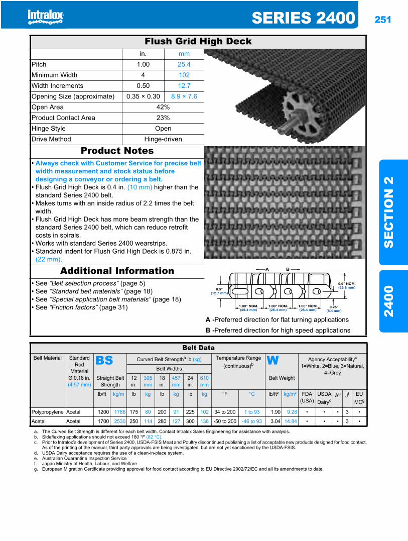
SERIES 2400 251
SE
CT
ION
224
00
Flush Grid High Deckin. mm
Pitch 1.00 25.4Minimum Width 4 102Width Increments 0.50 12.7Opening Size (approximate) 0.35 × 0.30 8.9 × 7.6Open Area 42%Product Contact Area 23%Hinge Style OpenDrive Method Hinge-driven
Product Notes• Always check with Customer Service for precise belt
width measurement and stock status before designing a conveyor or ordering a belt.
• Flush Grid High Deck is 0.4 in. (10 mm) higher than the standard Series 2400 belt.
• Makes turns with an inside radius of 2.2 times the belt width.
• Flush Grid High Deck has more beam strength than the standard Series 2400 belt, which can reduce retrofit costs in spirals.
• Works with standard Series 2400 wearstrips.• Standard indent for Flush Grid High Deck is 0.875 in.
(22 mm).
Additional Information• See “Belt selection process” (page 5)• See “Standard belt materials” (page 18)• See “Special application belt materials” (page 18)• See “Friction factors” (page 31)
A -Preferred direction for flat turning applicationsB -Preferred direction for high speed applications
Belt DataBelt Material Standard
RodMaterial
Ø 0.18 in. (4.57 mm)
BS Curved Belt Strengtha lb (kg) Temperature Range (continuous)b W Agency Acceptabilityc
1=White, 2=Blue, 3=Natural, 4=Grey
Belt Widths
Straight Belt Strength
12 in.
305 mm
18 in.
457mm
24in.
610 mm
Belt Weight
lb/ft kg/m lb kg lb kg lb kg °F °C lb/ft² kg/m² FDA (USA)
USDADairyd
Ae Jf EU MCg
Polypropylene Acetal 1200 1786 175 80 200 91 225 102 34 to 200 1 to 93 1.90 9.28 • • • 3 •
Acetal Acetal 1700 2530 250 114 280 127 300 136 -50 to 200 -46 to 93 3.04 14.84 • • • 3 •
a. The Curved Belt Strength is different for each belt width. Contact Intralox Sales Engineering for assistance with analysis.b. Sideflexing applications should not exceed 180 °F (82 °C).c. Prior to Intralox’s development of Series 2400, USDA-FSIS Meat and Poultry discontinued publishing a list of acceptable new products designed for food contact.
As of the printing of the manual, third party approvals are being investigated, but are not yet sanctioned by the USDA-FSIS.d. USDA Dairy acceptance requires the use of a clean-in-place system.e. Australian Quarantine Inspection Servicef. Japan Ministry of Health, Labour, and Welfareg. European Migration Certificate providing approval for food contact according to EU Directive 2002/72/EC and all its amendments to date.
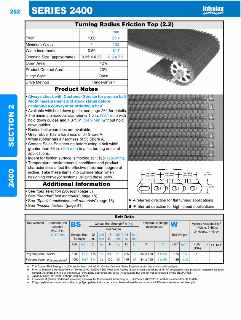
252 SERIES 2400S
EC
TIO
N 2
2400
Turning Radius Friction Top (2.2)in. mm
Pitch 1.00 25.4Minimum Width 4 102Width Increments 0.50 12.7Opening Size (approximate) 0.35 × 0.30 8.9 × 7.6Open Area 42%Product Contact Area 23%Hinge Style OpenDrive Method Hinge-driven
Product Notes• Always check with Customer Service for precise belt
width measurement and stock status before designing a conveyor or ordering a belt.
• Available with hold down guide, see page 261 for details.• The minimum nosebar diameter is 1.5 in. (38.1 mm) with
hold down guides and 1.375 in. (34.9 mm) without hold down guides.
• Radius belt wearstrips are available.• Grey rubber has a hardness of 64 Shore A.• White rubber has a hardness of 55 Shore A.• Contact Sales Engineering before using a belt width
greater than 36 in. (914 mm) in a flat turning or spiral applications.
• Indent for friction surface is molded at 1.125" (28.6mm).• Temperature, environmental conditions and product
characteristics affect the effective maximum degree of incline. Take these items into consideration when designing conveyor systems utilizing these belts.
Additional Information• See “Belt selection process” (page 5)• See “Standard belt materials” (page 18)• See “Special application belt materials” (page 18)• See “Friction factors” (page 31)
A -Preferred direction for flat turning applicationsB -Preferred direction for high speed applications
Belt DataBelt Material Standard Rod
MaterialØ 0.18 in. (4.57 mm)
BS Curved Belt Strengtha lb (kg) Temperature Range (continuous) W Agency Acceptabilityb
1=White, 2=Blue, 3=Natural, 4=Grey
Belt Widths
Straight Belt Strength
12 in.
305 mm
18 in.
457 mm
24 in.
610 mm
Belt Weight
lb/ft kg/m lb kg lb kg lb kg °F °C lb/ft² kg/m² FDA(USA)
Jc EU MCd
Polypropylene Acetal 1200 1785 175 80 200 91 225 102 34 to 150 1 to 66 1.35 6.59 1
Polypropylene Polypropylenee 1000 1487 114 52 130 59 146 67 34 to 150 1 to 66 1.29 6.30 1
a. The Curved Belt Strength is different for each belt width. Contact Intralox Sales Engineering for assistance with analysis.b. Prior to Intralox’s development of Series 2400, USDA-FSIS Meat and Poultry discontinued publishing a list of acceptable new products designed for food
contact. As of the printing of the manual, third party approvals are being investigated, but are not yet sanctioned by the USDA-FSIS.c. Japan Ministry of Health, Labour, and Welfared. European Migration Certificate providing approval for food contact according to EU Directive 2002/72/EC and all its amendments to date.e. Polypropylene rods can be installed in polypropylene belts when extra chemical resistance is required. Please note lower belt strength.
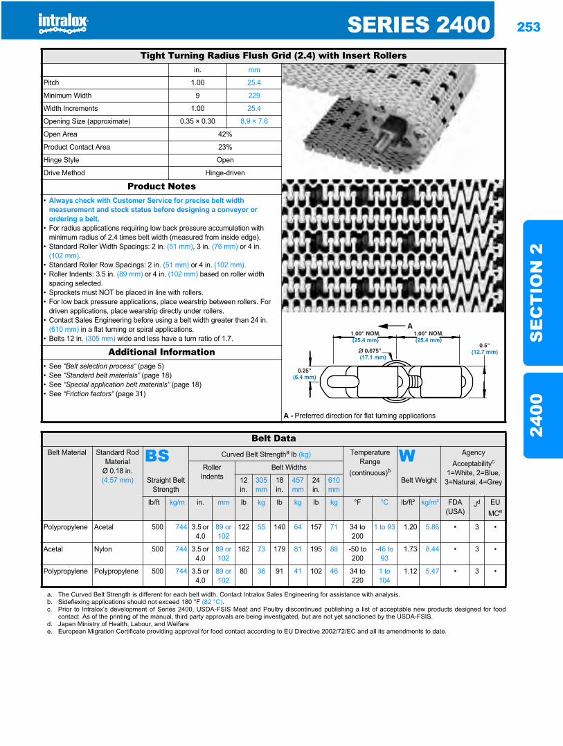
SERIES 2400 253
SE
CT
ION
224
00
Tight Turning Radius Flush Grid (2.4) with Insert Rollersin. mm
Pitch 1.00 25.4
Minimum Width 9 229
Width Increments 1.00 25.4
Opening Size (approximate) 0.35 × 0.30 8.9 × 7.6
Open Area 42%
Product Contact Area 23%
Hinge Style Open
Drive Method Hinge-driven
Product Notes• Always check with Customer Service for precise belt width
measurement and stock status before designing a conveyor or ordering a belt.
• For radius applications requiring low back pressure accumulation with minimum radius of 2.4 times belt width (measured from inside edge).
• Standard Roller Width Spacings: 2 in. (51 mm), 3 in. (76 mm) or 4 in. (102 mm).
• Standard Roller Row Spacings: 2 in. (51 mm) or 4 in. (102 mm).• Roller Indents: 3.5 in. (89 mm) or 4 in. (102 mm) based on roller width
spacing selected.• Sprockets must NOT be placed in line with rollers.• For low back pressure applications, place wearstrip between rollers. For
driven applications, place wearstrip directly under rollers.• Contact Sales Engineering before using a belt width greater than 24 in.
(610 mm) in a flat turning or spiral applications.• Belts 12 in. (305 mm) wide and less have a turn ratio of 1.7.
Additional Information• See “Belt selection process” (page 5)• See “Standard belt materials” (page 18)• See “Special application belt materials” (page 18)• See “Friction factors” (page 31)
A - Preferred direction for flat turning applications
Belt DataBelt Material Standard Rod
MaterialØ 0.18 in. (4.57 mm)
BS Curved Belt Strengtha lb (kg) Temperature Range
(continuous)bW Agency
Acceptabilityc
1=White, 2=Blue, 3=Natural, 4=Grey
Roller Indents
Belt Widths
Straight Belt Strength
12in.
305mm
18in.
457 mm
24 in.
610 mm
Belt Weight
lb/ft kg/m in. mm lb kg lb kg lb kg °F °C lb/ft² kg/m² FDA(USA)
Jd EUMCe
Polypropylene Acetal 500 744 3.5 or 4.0
89 or 102
122 55 140 64 157 71 34 to 200
1 to 93 1.20 5.86 • 3 •
Acetal Nylon 500 744 3.5 or 4.0
89 or 102
162 73 179 81 195 88 -50 to 200
-46 to 93
1.73 8.44 • 3 •
Polypropylene Polypropylene 500 744 3.5 or 4.0
89 or 102
80 36 91 41 102 46 34 to 220
1 to 104
1.12 5.47 • 3 •
a. The Curved Belt Strength is different for each belt width. Contact Intralox Sales Engineering for assistance with analysis.b. Sideflexing applications should not exceed 180 °F (82 °C).c. Prior to Intralox’s development of Series 2400, USDA-FSIS Meat and Poultry discontinued publishing a list of acceptable new products designed for food
contact. As of the printing of the manual, third party approvals are being investigated, but are not yet sanctioned by the USDA-FSIS.d. Japan Ministry of Health, Labour, and Welfaree. European Migration Certificate providing approval for food contact according to EU Directive 2002/72/EC and all its amendments to date.
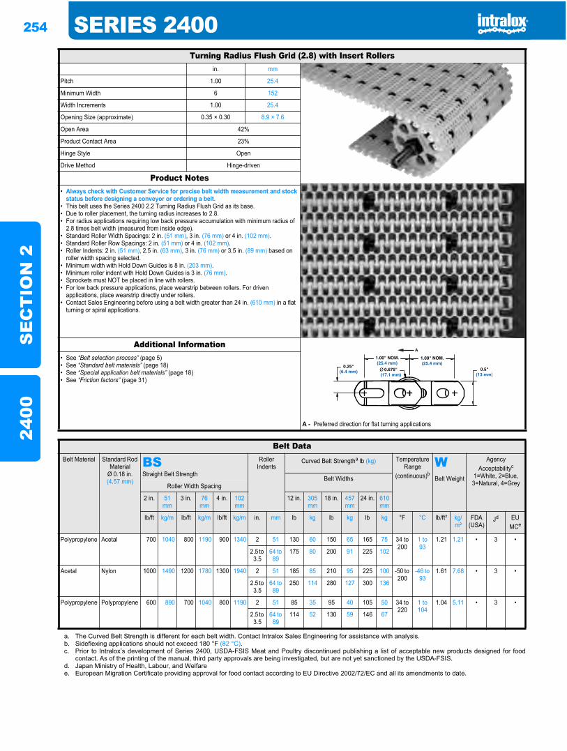
254 SERIES 2400S
EC
TIO
N 2
2400
Turning Radius Flush Grid (2.8) with Insert Rollersin. mm
Pitch 1.00 25.4
Minimum Width 6 152
Width Increments 1.00 25.4
Opening Size (approximate) 0.35 × 0.30 8.9 × 7.6
Open Area 42%
Product Contact Area 23%
Hinge Style Open
Drive Method Hinge-driven
Product Notes• Always check with Customer Service for precise belt width measurement and stock
status before designing a conveyor or ordering a belt.• This belt uses the Series 2400 2.2 Turning Radius Flush Grid as its base. • Due to roller placement, the turning radius increases to 2.8.• For radius applications requiring low back pressure accumulation with minimum radius of
2.8 times belt width (measured from inside edge).• Standard Roller Width Spacings: 2 in. (51 mm), 3 in. (76 mm) or 4 in. (102 mm).• Standard Roller Row Spacings: 2 in. (51 mm) or 4 in. (102 mm).• Roller Indents: 2 in. (51 mm), 2.5 in. (63 mm), 3 in. (76 mm) or 3.5 in. (89 mm) based on
roller width spacing selected.• Minimum width with Hold Down Guides is 8 in. (203 mm).• Minimum roller indent with Hold Down Guides is 3 in. (76 mm).• Sprockets must NOT be placed in line with rollers.• For low back pressure applications, place wearstrip between rollers. For driven
applications, place wearstrip directly under rollers.• Contact Sales Engineering before using a belt width greater than 24 in. (610 mm) in a flat
turning or spiral applications.
Additional Information• See “Belt selection process” (page 5)• See “Standard belt materials” (page 18)• See “Special application belt materials” (page 18)• See “Friction factors” (page 31)
A - Preferred direction for flat turning applications
Belt DataBelt Material Standard Rod
MaterialØ 0.18 in.(4.57 mm)
BSStraight Belt Strength
Roller Indents
Curved Belt Strengtha lb (kg) Temperature Range
(continuous)bW Agency
Acceptabilityc
1=White, 2=Blue, 3=Natural, 4=Grey
Belt Widths Belt WeightRoller Width Spacing
2 in. 51mm
3 in. 76mm
4 in. 102 mm
12 in. 305mm
18 in. 457 mm
24 in. 610 mm
lb/ft kg/m lb/ft kg/m lb/ft kg/m in. mm lb kg lb kg lb kg °F °C lb/ft² kg/m²
FDA (USA)
Jd EUMCe
Polypropylene Acetal 700 1040 800 1190 900 1340 2 51 130 60 150 65 165 75 34 to 200
1 to 93
1.21 1.21 • 3 •
2.5 to 3.5
64 to 89
175 80 200 91 225 102
Acetal Nylon 1000 1490 1200 1780 1300 1940 2 51 185 85 210 95 225 100 -50 to 200
-46 to 93
1.61 7.68 • 3 •
2.5 to 3.5
64 to 89
250 114 280 127 300 136
Polypropylene Polypropylene 600 890 700 1040 800 1190 2 51 85 35 95 40 105 50 34 to 220
1 to 104
1.04 5.11 • 3 •
2.5 to 3.5
64 to 89
114 52 130 59 146 67
a. The Curved Belt Strength is different for each belt width. Contact Intralox Sales Engineering for assistance with analysis.b. Sideflexing applications should not exceed 180 °F (82 °C).c. Prior to Intralox’s development of Series 2400, USDA-FSIS Meat and Poultry discontinued publishing a list of acceptable new products designed for food
contact. As of the printing of the manual, third party approvals are being investigated, but are not yet sanctioned by the USDA-FSIS.d. Japan Ministry of Health, Labour, and Welfaree. European Migration Certificate providing approval for food contact according to EU Directive 2002/72/EC and all its amendments to date.
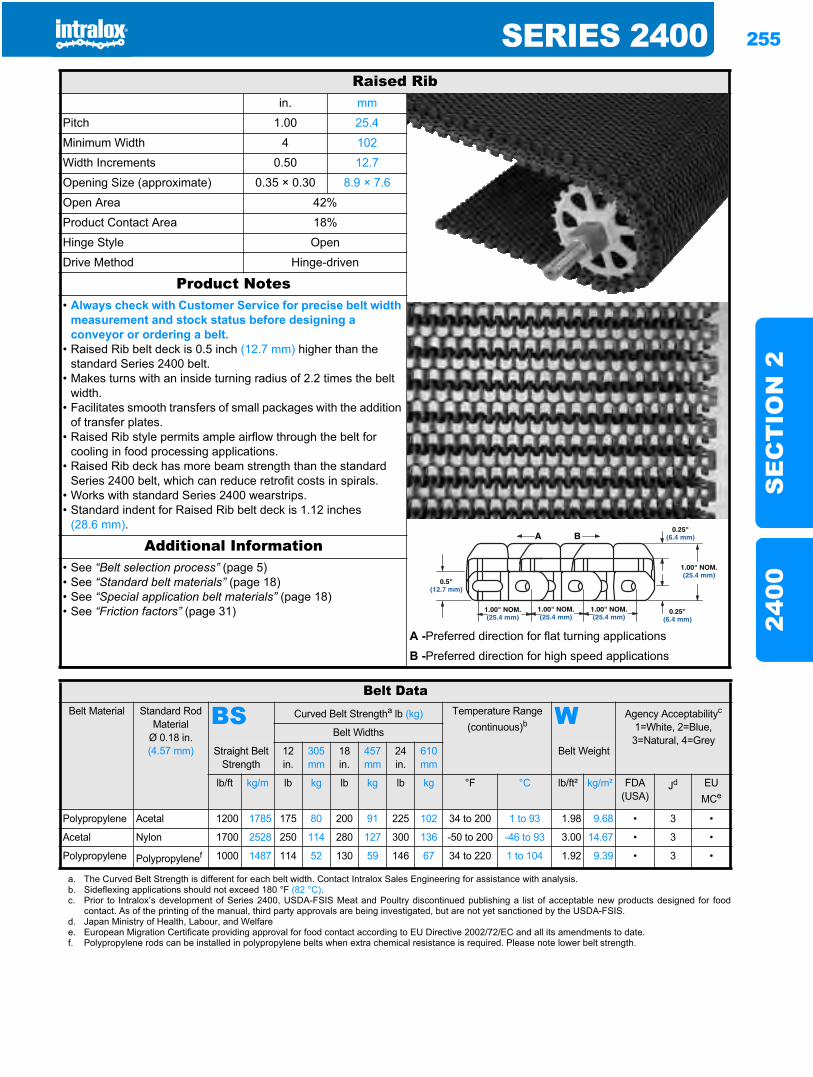
SERIES 2400 255
SE
CT
ION
224
00
Raised Ribin. mm
Pitch 1.00 25.4
Minimum Width 4 102
Width Increments 0.50 12.7
Opening Size (approximate) 0.35 × 0.30 8.9 × 7.6
Open Area 42%
Product Contact Area 18%
Hinge Style Open
Drive Method Hinge-driven
Product Notes• Always check with Customer Service for precise belt width
measurement and stock status before designing a conveyor or ordering a belt.
• Raised Rib belt deck is 0.5 inch (12.7 mm) higher than the standard Series 2400 belt.
• Makes turns with an inside turning radius of 2.2 times the belt width.
• Facilitates smooth transfers of small packages with the addition of transfer plates.
• Raised Rib style permits ample airflow through the belt for cooling in food processing applications.
• Raised Rib deck has more beam strength than the standard Series 2400 belt, which can reduce retrofit costs in spirals.
• Works with standard Series 2400 wearstrips.• Standard indent for Raised Rib belt deck is 1.12 inches
(28.6 mm).
Additional Information• See “Belt selection process” (page 5)• See “Standard belt materials” (page 18)• See “Special application belt materials” (page 18)• See “Friction factors” (page 31)
A -Preferred direction for flat turning applications
B -Preferred direction for high speed applications
Belt DataBelt Material Standard Rod
MaterialØ 0.18 in. (4.57 mm)
BS Curved Belt Strengtha lb (kg) Temperature Range (continuous)b W Agency Acceptabilityc
1=White, 2=Blue, 3=Natural, 4=Grey
Belt Widths
Straight Belt Strength
12 in.
305 mm
18in.
457 mm
24 in.
610 mm
Belt Weight
lb/ft kg/m lb kg lb kg lb kg °F °C lb/ft² kg/m² FDA (USA)
Jd EUMCe
Polypropylene Acetal 1200 1785 175 80 200 91 225 102 34 to 200 1 to 93 1.98 9.68 • 3 •
Acetal Nylon 1700 2528 250 114 280 127 300 136 -50 to 200 -46 to 93 3.00 14.67 • 3 •
Polypropylene Polypropylenef 1000 1487 114 52 130 59 146 67 34 to 220 1 to 104 1.92 9.39 • 3 •
a. The Curved Belt Strength is different for each belt width. Contact Intralox Sales Engineering for assistance with analysis.b. Sideflexing applications should not exceed 180 °F (82 °C).c. Prior to Intralox’s development of Series 2400, USDA-FSIS Meat and Poultry discontinued publishing a list of acceptable new products designed for food
contact. As of the printing of the manual, third party approvals are being investigated, but are not yet sanctioned by the USDA-FSIS.d. Japan Ministry of Health, Labour, and Welfaree. European Migration Certificate providing approval for food contact according to EU Directive 2002/72/EC and all its amendments to date.f. Polypropylene rods can be installed in polypropylene belts when extra chemical resistance is required. Please note lower belt strength.
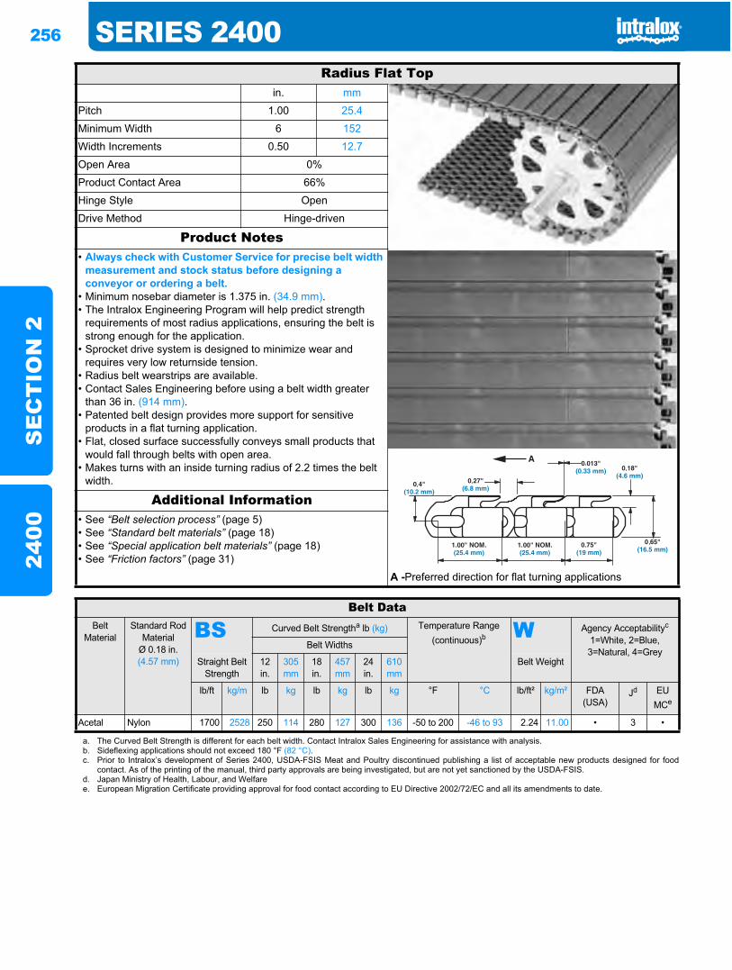
256 SERIES 2400S
EC
TIO
N 2
2400
Radius Flat Topin. mm
Pitch 1.00 25.4
Minimum Width 6 152
Width Increments 0.50 12.7
Open Area 0%
Product Contact Area 66%
Hinge Style Open
Drive Method Hinge-driven
Product Notes• Always check with Customer Service for precise belt width
measurement and stock status before designing a conveyor or ordering a belt.
• Minimum nosebar diameter is 1.375 in. (34.9 mm).• The Intralox Engineering Program will help predict strength
requirements of most radius applications, ensuring the belt is strong enough for the application.
• Sprocket drive system is designed to minimize wear and requires very low returnside tension.
• Radius belt wearstrips are available.• Contact Sales Engineering before using a belt width greater
than 36 in. (914 mm).• Patented belt design provides more support for sensitive
products in a flat turning application.• Flat, closed surface successfully conveys small products that
would fall through belts with open area.• Makes turns with an inside turning radius of 2.2 times the belt
width.
Additional Information• See “Belt selection process” (page 5)• See “Standard belt materials” (page 18)• See “Special application belt materials” (page 18)• See “Friction factors” (page 31)
A -Preferred direction for flat turning applications
Belt DataBelt
MaterialStandard Rod
MaterialØ 0.18 in. (4.57 mm)
BS Curved Belt Strengtha lb (kg) Temperature Range (continuous)b W Agency Acceptabilityc
1=White, 2=Blue, 3=Natural, 4=Grey
Belt Widths
Straight Belt Strength
12 in.
305 mm
18 in.
457 mm
24 in.
610 mm
Belt Weight
lb/ft kg/m lb kg lb kg lb kg °F °C lb/ft² kg/m² FDA(USA)
Jd EUMCe
Acetal Nylon 1700 2528 250 114 280 127 300 136 -50 to 200 -46 to 93 2.24 11.00 • 3 •
a. The Curved Belt Strength is different for each belt width. Contact Intralox Sales Engineering for assistance with analysis.b. Sideflexing applications should not exceed 180 °F (82 °C).c. Prior to Intralox’s development of Series 2400, USDA-FSIS Meat and Poultry discontinued publishing a list of acceptable new products designed for food
contact. As of the printing of the manual, third party approvals are being investigated, but are not yet sanctioned by the USDA-FSIS.d. Japan Ministry of Health, Labour, and Welfaree. European Migration Certificate providing approval for food contact according to EU Directive 2002/72/EC and all its amendments to date.
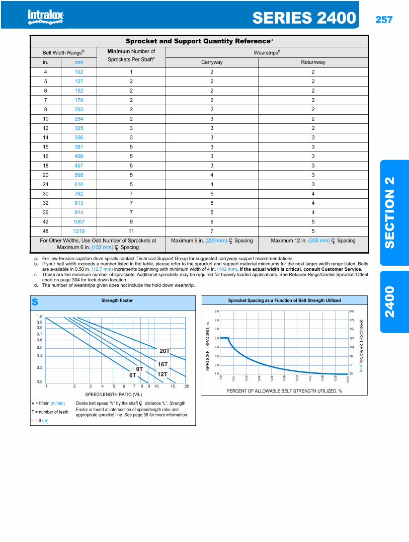
SERIES 2400 257
SE
CT
ION
224
00
Sprocket and Support Quantity Referencea
Belt Width Rangeb Minimum Number of Sprockets Per Shaftc
Wearstripsd
in. mm Carryway Returnway
4 102 1 2 2
5 127 2 2 2
6 152 2 2 2
7 178 2 2 2
8 203 2 2 2
10 254 2 3 2
12 305 3 3 2
14 356 3 3 3
15 381 5 3 3
16 406 5 3 3
18 457 5 3 3
20 508 5 4 3
24 610 5 4 3
30 762 7 5 4
32 813 7 5 4
36 914 7 5 4
42 1067 9 6 5
48 1219 11 7 5
For Other Widths, Use Odd Number of Sprockets at Maximum 6 in. (152 mm) CL Spacing
Maximum 9 in. (229 mm) CL Spacing Maximum 12 in. (305 mm) CL Spacing
a. For low-tension capstan drive spirals contact Technical Support Group for suggested carryway support recommendations.b. If your belt width exceeds a number listed in the table, please refer to the sprocket and support material minimums for the next larger width range listed. Belts
are available in 0.50 in. (12.7 mm) increments beginning with minimum width of 4 in. (102 mm). If the actual width is critical, consult Customer Service.c. These are the minimum number of sprockets. Additional sprockets may be required for heavily loaded applications. See Retainer Rings/Center Sprocket Offset
chart on page 304 for lock down location.d. The number of wearstrips given does not include the hold down wearstrip.
S Strength Factor
SPEED/LENGTH RATIO (V/L)
V = ft/min (m/min) Divide belt speed “V” by the shaft CL distance “L”. Strength Factor is found at intersection of speed/length ratio and appropriate sprocket line. See page 36 for more information.T = number of teeth
L = ft (m)
1.00.90.8
0.70.6
0.5
0.4
0.3
0.21 2 3 4 5 6 7 8 9 10 15 20
Sprocket Spacing as a Function of Belt Strength Utilized
SPRO
CKET
SPA
CING
, in.
SPROCKET SPACING
, mm
PERCENT OF ALLOWABLE BELT STRENGTH UTILIZED, %
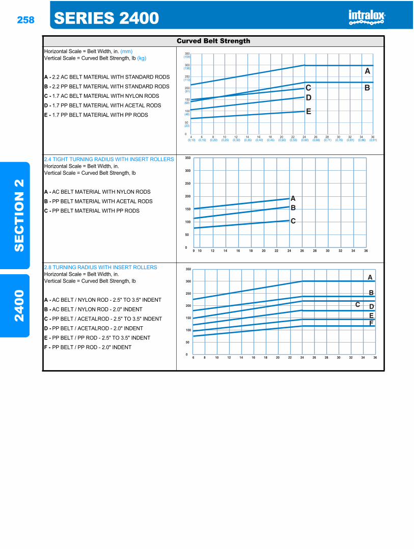
258 SERIES 2400S
EC
TIO
N 2
2400
Curved Belt StrengthHorizontal Scale = Belt Width, in. (mm)Vertical Scale = Curved Belt Strength, lb (kg)
A - 2.2 AC BELT MATERIAL WITH STANDARD RODS
B - 2.2 PP BELT MATERIAL WITH STANDARD RODS
C - 1.7 AC BELT MATERIAL WITH NYLON RODS
D - 1.7 PP BELT MATERIAL WITH ACETAL RODS
E - 1.7 PP BELT MATERIAL WITH PP RODS
2.4 TIGHT TURNING RADIUS WITH INSERT ROLLERSHorizontal Scale = Belt Width, in.Vertical Scale = Curved Belt Strength, lb
A - AC BELT MATERIAL WITH NYLON RODS
B - PP BELT MATERIAL WITH ACETAL RODS
C - PP BELT MATERIAL WITH PP RODS
2.8 TURNING RADIUS WITH INSERT ROLLERSHorizontal Scale = Belt Width, in.Vertical Scale = Curved Belt Strength, lb
A - AC BELT / NYLON ROD - 2.5" TO 3.5" INDENT
B - AC BELT / NYLON ROD - 2.0" INDENT
C - PP BELT / ACETALROD - 2.5" TO 3.5" INDENT
D - PP BELT / ACETALROD - 2.0" INDENT
E - PP BELT / PP ROD - 2.5" TO 3.5" INDENT
F - PP BELT / PP ROD - 2.0" INDENT
4 6 8 10 12 14 16 18 20 22 24 26 28 30 32 34 36(0,10) (0,15) (0,20) (0,25) (0,30) (0,35) (0,40) (0,45) (0,50) (0,55) (0,60) (0,66) (0,71) (0,76) (0,81) (0,86) (0,91)
350
300
250
200
150
100
50
0
(159)
(136)
(113)
(91)
(68)
(46)
(23)
350
300
250
200
150
100
50
09 10 12 14 16 18 20 22 24 26 28 30 32 34 36
350
300
250
200
150
100
50
06 8 10 12 14 16 18 20 22 24 26 28 30 32 34 36
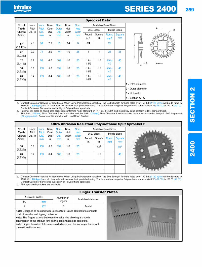
SERIES 2400 259
SE
CT
ION
224
00
Sprocket Dataa
No. of Teeth
(Chordal Action)
Nom. Pitch
Dia. in.
Nom. Pitch Dia. mm
Nom. Outer Dia.in.
Nom. OuterDia. mm
Nom. Hub
Width in.
Nom. Hub
Width mm
Available Bore Sizes
U.S. Sizes Metric Sizes
Round in.b
Square in.
Round mmb
Square mm
6c
(13.40%)2.0 51 2.0 51 .54 14 3/4 20
9c
(6.03%)2.9 74 2.9 74 1.0 25 1 1 25 25
12(3.41%)
3.9 99 4.0 102 1.0 25 1 to1-1/2
1.5 25 to 40
40
16(1.92%)
5.1 130 5.2 132 1.0 25 1 to1-1/2
1.5 25 to 40
40
20(1.23%)
6.4 163 6.4 163 1.0 25 1 to1-1/2
1.5 25 to 40
40
1 - Pitch diameter
2 - Outer diameter
3 - Hub width
4 - Section A - A
a. Contact Customer Service for lead times. When using Polyurethane sprockets, the Belt Strength for belts rated over 750 lb/ft (1120 kg/m) will be de-rated to750 lb/ft (1120 kg/m) and all other belts will maintain their published rating. The temperature range for Polyurethane sprockets is 0 °F (-18 °C) to 120 °F (49 °C).Contact Customer Service for availability of Polyurethane sprockets.
b. Imperial key sizes on round bore sprockets conform to ANSI standard B17.1-1967 (R1989) and metric key sizes conform to DIN standard 6885.c. The 2.0 in. (51 mm) Pitch Diameter 6 tooth sprocket and the 2.9 in. (74 mm) Pitch Diameter 9 tooth sprocket have a recommended belt pull of 60 lb/sprocket
(27 kg/sprocket). Do not use this sprocket with Hold Down Guides.
Ultra Abrasion Resistant Polyurethane Split Sprocketsa
No. of Teeth
(Chordal Action)
Nom. Pitch
Dia. in.
Nom. Pitch Dia. mm
Nom. Outer Dia.in.
Nom. OuterDia. mm
Nom. Hub
Width in.
Nom. Hub
Width mm
Available Bore Sizes
U.S. Sizes Metric Sizes
Round in.
Square in.
Round mm
Square mm
16(1.92%)
5.1 130 5.2 132 1.0 25 1.5b 40b
20(1.23%)
6.4 163 6.4 163 1.0 25 1.5 40
a. Contact Customer Service for lead times. When using Polyurethane sprockets, the Belt Strength for belts rated over 750 lb/ft (1120 kg/m) will be de-rated to750 lb/ft (1120 kg/m) and all other belts will maintain their published rating. The temperature range for Polyurethane sprockets is 0 °F (-18 °C) to 120 °F (49 °C).Contact Customer Service for availability of Polyurethane sprockets.
b. FDA approved sprockets are available.
Finger Transfer PlatesAvailable Widths Number of
Fingers Available Materialsin. mm
4 102 16 Acetal
Note: Designed to be used with Series 2400 Raised Rib belts to eliminate product transfer and tipping problems.Note: The fingers extend between the belt’s ribs allowing a smooth continuation of the product flow as the belt engages its sprockets.Note: Finger Transfer Plates are installed easily on the conveyor frame with conventional fasteners.
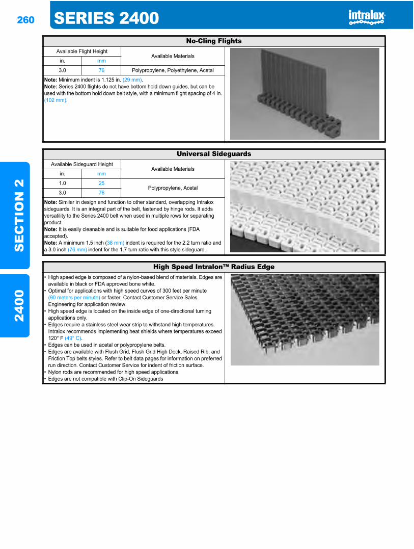
260 SERIES 2400S
EC
TIO
N 2
2400
No-Cling FlightsAvailable Flight Height
Available Materialsin. mm
3.0 76 Polypropylene, Polyethylene, Acetal
Note: Minimum indent is 1.125 in. (29 mm).Note: Series 2400 flights do not have bottom hold down guides, but can be used with the bottom hold down belt style, with a minimum flight spacing of 4 in. (102 mm).
Universal SideguardsAvailable Sideguard Height
Available Materialsin. mm
1.0 25Polypropylene, Acetal
3.0 76
Note: Similar in design and function to other standard, overlapping Intralox sideguards. It is an integral part of the belt, fastened by hinge rods. It adds versatility to the Series 2400 belt when used in multiple rows for separating product. Note: It is easily cleanable and is suitable for food applications (FDA accepted). Note: A minimum 1.5 inch (38 mm) indent is required for the 2.2 turn ratio and a 3.0 inch (76 mm) indent for the 1.7 turn ratio with this style sideguard.
High Speed Intralon™ Radius Edge• High speed edge is composed of a nylon-based blend of materials. Edges are
available in black or FDA approved bone white.• Optimal for applications with high speed curves of 300 feet per minute
(90 meters per minute) or faster. Contact Customer Service Sales Engineering for application review.
• High speed edge is located on the inside edge of one-directional turning applications only.
• Edges require a stainless steel wear strip to withstand high temperatures. Intralox recommends implementing heat shields where temperatures exceed 120° F (49° C).
• Edges can be used in acetal or polypropylene belts.• Edges are available with Flush Grid, Flush Grid High Deck, Raised Rib, and
Friction Top belts styles. Refer to belt data pages for information on preferred run direction. Contact Customer Service for indent of friction surface.
• Nylon rods are recommended for high speed applications.• Edges are not compatible with Clip-On Sideguards
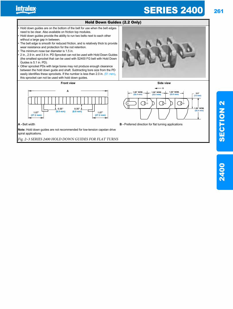
SERIES 2400 261
SE
CT
ION
224
00
Hold Down Guides (2.2 Only)• Hold down guides are on the bottom of the belt for use when the belt edges
need to be clear. Also available on friction top modules.• Hold down guides provide the ability to run two belts next to each other
without a large gap in between.• The belt edge is smooth for reduced friction, and is relatively thick to provide
wear resistance and protection for the rod retention.• The minimum nose bar diameter is 1.5 in.• 2 in., 2.9 in. and 3.9 in. PD Sprocket can not be used with Hold Down Guides
(the smallest sprocket that can be used with S2400 FG belt with Hold Down Guides is 5.1 in. PD).
• Other sprocket PDs with large bores may not produce enough clearance between the hold down guide and shaft. Subtracting bore size from the PD easily identifies these sprockets. If the number is less than 2.0 in. (51 mm),this sprocket can not be used with hold down guides.
Front view Side view
A - Belt width B - Preferred direction for flat turning applications
Note: Hold down guides are not recommended for low-tension capstan drive spiral applications.
Fig. 2–3 SERIES 2400 HOLD DOWN GUIDES FOR FLAT TURNS
A
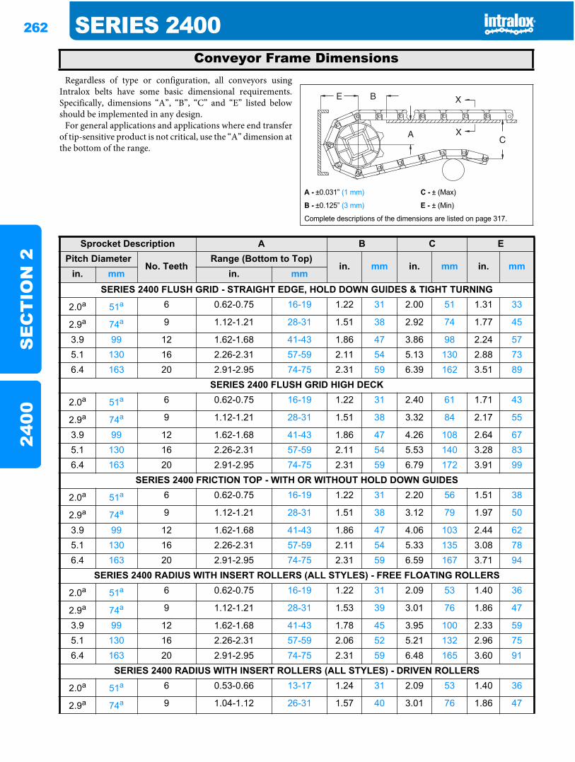
262 SERIES 2400S
EC
TIO
N 2
2400
Regardless of type or configuration, all conveyors usingIntralox belts have some basic dimensional requirements.Specifically, dimensions “A”, “B”, “C” and “E” listed belowshould be implemented in any design.
For general applications and applications where end transferof tip-sensitive product is not critical, use the “A” dimension atthe bottom of the range.
Conveyor Frame Dimensions
A - ±0.031” (1 mm) C - ± (Max)
B - ±0.125” (3 mm) E - ± (Min)
Complete descriptions of the dimensions are listed on page 317.
Sprocket Description A B C EPitch Diameter
No. TeethRange (Bottom to Top)
in. mm in. mm in. mmin. mm in. mm
SERIES 2400 FLUSH GRID - STRAIGHT EDGE, HOLD DOWN GUIDES & TIGHT TURNING
2.0a 51a 6 0.62-0.75 16-19 1.22 31 2.00 51 1.31 33
2.9a 74a 9 1.12-1.21 28-31 1.51 38 2.92 74 1.77 45
3.9 99 12 1.62-1.68 41-43 1.86 47 3.86 98 2.24 575.1 130 16 2.26-2.31 57-59 2.11 54 5.13 130 2.88 736.4 163 20 2.91-2.95 74-75 2.31 59 6.39 162 3.51 89
SERIES 2400 FLUSH GRID HIGH DECK
2.0a 51a 6 0.62-0.75 16-19 1.22 31 2.40 61 1.71 43
2.9a 74a 9 1.12-1.21 28-31 1.51 38 3.32 84 2.17 55
3.9 99 12 1.62-1.68 41-43 1.86 47 4.26 108 2.64 675.1 130 16 2.26-2.31 57-59 2.11 54 5.53 140 3.28 836.4 163 20 2.91-2.95 74-75 2.31 59 6.79 172 3.91 99
SERIES 2400 FRICTION TOP - WITH OR WITHOUT HOLD DOWN GUIDES
2.0a 51a 6 0.62-0.75 16-19 1.22 31 2.20 56 1.51 38
2.9a 74a 9 1.12-1.21 28-31 1.51 38 3.12 79 1.97 50
3.9 99 12 1.62-1.68 41-43 1.86 47 4.06 103 2.44 625.1 130 16 2.26-2.31 57-59 2.11 54 5.33 135 3.08 786.4 163 20 2.91-2.95 74-75 2.31 59 6.59 167 3.71 94
SERIES 2400 RADIUS WITH INSERT ROLLERS (ALL STYLES) - FREE FLOATING ROLLERS
2.0a 51a 6 0.62-0.75 16-19 1.22 31 2.09 53 1.40 36
2.9a 74a 9 1.12-1.21 28-31 1.53 39 3.01 76 1.86 47
3.9 99 12 1.62-1.68 41-43 1.78 45 3.95 100 2.33 595.1 130 16 2.26-2.31 57-59 2.06 52 5.21 132 2.96 756.4 163 20 2.91-2.95 74-75 2.31 59 6.48 165 3.60 91
SERIES 2400 RADIUS WITH INSERT ROLLERS (ALL STYLES) - DRIVEN ROLLERS
2.0a 51a 6 0.53-0.66 13-17 1.24 31 2.09 53 1.40 36
2.9a 74a 9 1.04-1.12 26-31 1.57 40 3.01 76 1.86 47
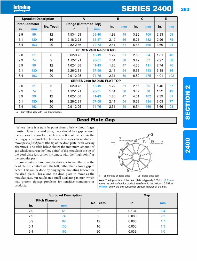
SERIES 2400 263
SE
CT
ION
224
00
Where there is a transfer point from a belt without fingertransfer plates to a dead plate, there should be a gap betweenthe surfaces to allow for the chordal action of the belt. As thebelt engages its sprockets, chordal action causes the modules tomove past a fixed point (the tip of the dead plate) with varyingclearances. The table below shows the minimum amount ofgap which occurs at the “low point” of the modules if the tip ofthe dead plate just comes in contact with the “high point” asthe modules pass.
In some installations it may be desirable to keep the tip of thedead plate in contact with the belt, rather than allow a gap tooccur. This can be done by hinging the mounting bracket forthe dead plate. This allows the dead plate to move as themodules pass, but results in a small oscillating motion whichmay present tippage problems for sensitive containers orproducts.
3.9 99 12 1.53-1.59 39-40 1.92 49 3.95 100 2.33 595.1 130 16 2.18-2.23 55-57 2.19 56 5.21 132 2.96 756.4 163 20 2.82-2.86 72-73 2.41 61 6.48 165 3.60 91
SERIES 2400 RAISED RIB2.0 51 6 0.62-0.75 16-19 1.22 31 2.50 64 1.81 462.9 74 9 1.12-1.21 28-31 1.51 38 3.42 87 2.27 583.9 99 12 1.62-1.68 41-43 1.86 47 4.36 111 2.74 705.1 130 16 2.26-2.31 57-59 2.11 54 5.63 143 3.38 866.4 163 20 2.91-2.95 74-75 2.31 59 6.89 175 4.01 102
SERIES 2400 RADIUS FLAT TOP2.0 51 6 0.62-0.75 16-19 1.22 31 2.15 55 1.46 372.9 74 9 1.12-1.21 28-31 1.51 38 3.07 78 1.92 493.9 99 12 1.62-1.68 41-43 1.86 47 4.01 102 2.39 615.1 130 16 2.26-2.31 57-59 2.11 54 5.28 134 3.03 776.4 163 20 2.91-2.95 74-75 2.31 59 6.54 166 3.66 93
a. Can not be used with Hold Down Guides.
Sprocket Description A B C EPitch Diameter
No. TeethRange (Bottom to Top)
in. mm in. mm in. mmin. mm in. mm
Dead Plate Gap
1 - Top surface of dead plate 2 - Dead plate gap
Note: The top surface of the dead plate is typically 0.031 in. (0.8 mm)above the belt surface for product transfer onto the belt, and 0.031 in. (0.8 mm) below the belt surface for product transfer off the belt.
21
Sprocket Description GapPitch Diameter
No. Teeth in. mmin. mm2.0 51 6 0.134 3.42.9 74 9 0.088 2.23.9 99 12 0.065 1.75.1 130 16 0.050 1.36.4 163 20 0.039 1.0
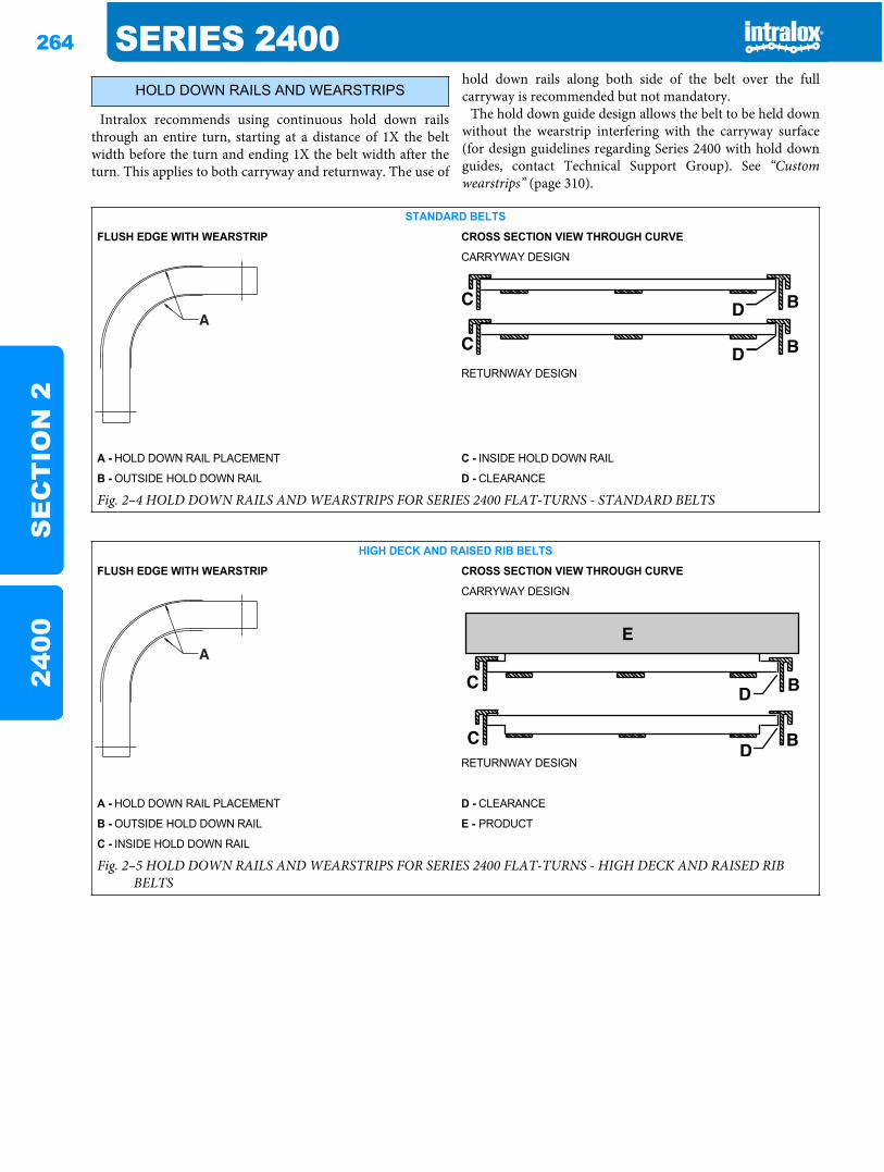
264 SERIES 2400S
EC
TIO
N 2
2400
Intralox recommends using continuous hold down railsthrough an entire turn, starting at a distance of 1X the beltwidth before the turn and ending 1X the belt width after theturn. This applies to both carryway and returnway. The use of
hold down rails along both side of the belt over the fullcarryway is recommended but not mandatory.
The hold down guide design allows the belt to be held downwithout the wearstrip interfering with the carryway surface(for design guidelines regarding Series 2400 with hold downguides, contact Technical Support Group). See “Customwearstrips” (page 310).
HOLD DOWN RAILS AND WEARSTRIPS
STANDARD BELTS
FLUSH EDGE WITH WEARSTRIP CROSS SECTION VIEW THROUGH CURVE
CARRYWAY DESIGN
RETURNWAY DESIGN
A - HOLD DOWN RAIL PLACEMENT C - INSIDE HOLD DOWN RAIL
B - OUTSIDE HOLD DOWN RAIL D - CLEARANCE
Fig. 2–4 HOLD DOWN RAILS AND WEARSTRIPS FOR SERIES 2400 FLAT-TURNS - STANDARD BELTS
HIGH DECK AND RAISED RIB BELTS
FLUSH EDGE WITH WEARSTRIP CROSS SECTION VIEW THROUGH CURVE
CARRYWAY DESIGN
RETURNWAY DESIGN
A - HOLD DOWN RAIL PLACEMENT D - CLEARANCE
B - OUTSIDE HOLD DOWN RAIL E - PRODUCT
C - INSIDE HOLD DOWN RAIL
Fig. 2–5 HOLD DOWN RAILS AND WEARSTRIPS FOR SERIES 2400 FLAT-TURNS - HIGH DECK AND RAISED RIB BELTS
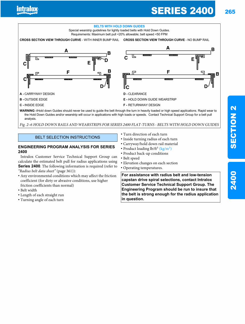
SERIES 2400 265
SE
CT
ION
224
00
ENGINEERING PROGRAM ANALYSIS FOR SERIES 2400
Intralox Customer Service Technical Support Group cancalculate the estimated belt pull for radius applications usingSeries 2400. The following information is required (refer to“Radius belt data sheet” (page 361)):• Any environmental conditions which may affect the friction
coefficient (for dirty or abrasive conditions, use higher friction coefficients than normal)
• Belt width• Length of each straight run• Turning angle of each turn
• Turn direction of each turn• Inside turning radius of each turn• Carryway/hold down rail material• Product loading lb/ft2 (kg/m2)• Product back-up conditions• Belt speed• Elevation changes on each section• Operating temperatures.
BELTS WITH HOLD DOWN GUIDESSpecial wearstrip guidelines for lightly loaded belts with Hold Down Guides.
Requirements: Maximum belt pull <20% allowable; belt speed <50 FPM
CROSS SECTION VIEW THROUGH CURVE - WITH INNER BUMP RAIL CROSS SECTION VIEW THROUGH CURVE - NO BUMP RAIL
A - CARRYWAY DESIGN D - CLEARANCE
B - OUTSIDE EDGE E - HOLD DOWN GUIDE WEARSTRIP
C - INSIDE EDGE F - RETURNWAY DESIGN
WARNING -IHold down Guides should never be used to guide the belt through the turn in heavily loaded or high speed applications. Rapid wear to the Hold Down Guides and/or wearstrip will occur in applications with high loads or speeds. Contact Technical Support Group for a belt pull analysis.
Fig. 2–6 HOLD DOWN RAILS AND WEARSTRIPS FOR SERIES 2400 FLAT-TURNS - BELTS WITH HOLD DOWN GUIDES
BELT SELECTION INSTRUCTIONS
For assistance with radius belt and low-tension capstan drive spiral selections, contact Intralox Customer Service Technical Support Group. The Engineering Program should be run to insure that the belt is strong enough for the radius application in question.
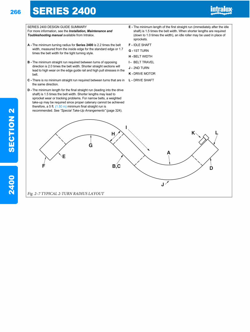
266 SERIES 2400S
EC
TIO
N 2
2400
SERIES 2400 DESIGN GUIDE SUMMARYFor more information, see the Installation, Maintenance and Toubleshooting manual available from Intralox.
E - The minimum length of the first straight run (immediately after the idle shaft) is 1.5 times the belt width. When shorter lengths are required (down to 1.0 times the width), an idle roller may be used in place of sprockets.
A - The minimum turning radius for Series 2400 is 2.2 times the belt width, measured from the inside edge for the standard edge or 1.7 times the belt width for the tight turning style.
F - IDLE SHAFT
G - 1ST TURN
H - BELT WIDTH
B - The minimum straight run required between turns of opposing direction is 2.0 times the belt width. Shorter straight sections will lead to high wear on the edge guide rail and high pull stresses in the belt.
I - BELT TRAVEL
J - 2ND TURN
K - DRIVE MOTOR
C - There is no minimum straight run required between turns that are in the same direction.
L - DRIVE SHAFT
D - The minimum length for the final straight run (leading into the drive shaft) is 1.5 times the belt width. Shorter lengths may lead to sprocket wear or tracking problems. For narrow belts, a weighted take-up may be required since proper catenary cannot be achieved therefore, a 5 ft. (1.50 m) minimum final straight run is recommended. See “Special Take-Up Arrangements” (page 324).
Fig. 2–7 TYPICAL 2-TURN RADIUS LAYOUT
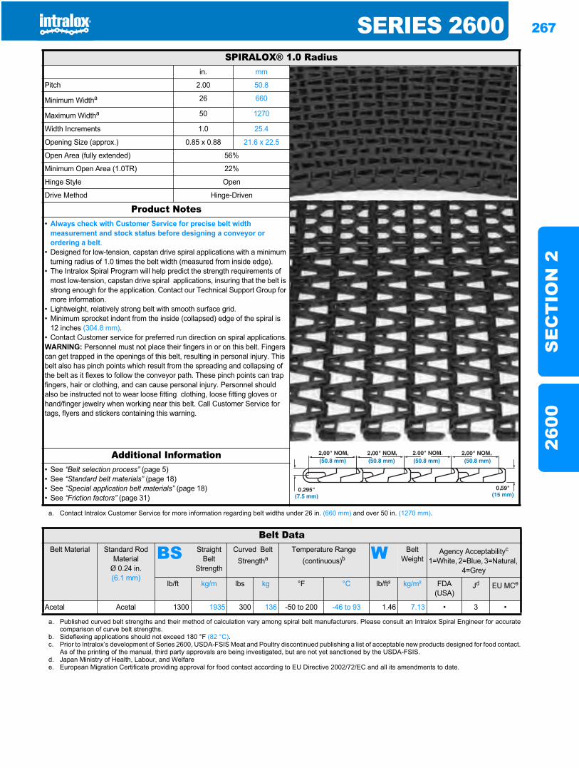
SERIES 2600 267
SE
CT
ION
226
00
Series 26002600
SPIRALOX® 1.0 Radiusin. mm
Pitch 2.00 50.8
Minimum Widtha 26 660
Maximum Widtha 50 1270
Width Increments 1.0 25.4
Opening Size (approx.) 0.85 x 0.88 21.6 x 22.5
Open Area (fully extended) 56%
Minimum Open Area (1.0TR) 22%
Hinge Style Open
Drive Method Hinge-Driven
Product Notes• Always check with Customer Service for precise belt width
measurement and stock status before designing a conveyor or ordering a belt.
• Designed for low-tension, capstan drive spiral applications with a minimum turning radius of 1.0 times the belt width (measured from inside edge).
• The Intralox Spiral Program will help predict the strength requirements of most low-tension, capstan drive spiral applications, insuring that the belt is strong enough for the application. Contact our Technical Support Group for more information.
• Lightweight, relatively strong belt with smooth surface grid.• Minimum sprocket indent from the inside (collapsed) edge of the spiral is
12 inches (304.8 mm).• Contact Customer service for preferred run direction on spiral applications.WARNING: Personnel must not place their fingers in or on this belt. Fingers can get trapped in the openings of this belt, resulting in personal injury. This belt also has pinch points which result from the spreading and collapsing of the belt as it flexes to follow the conveyor path. These pinch points can trap fingers, hair or clothing, and can cause personal injury. Personnel should also be instructed not to wear loose fitting clothing, loose fitting gloves or hand/finger jewelry when working near this belt. Call Customer Service for tags, flyers and stickers containing this warning.
Additional Information• See “Belt selection process” (page 5)• See “Standard belt materials” (page 18)• See “Special application belt materials” (page 18)• See “Friction factors” (page 31)
a. Contact Intralox Customer Service for more information regarding belt widths under 26 in. (660 mm) and over 50 in. (1270 mm).
Belt DataBelt Material Standard Rod
MaterialØ 0.24 in. (6.1 mm)
BS Straight Belt
Strength
Curved Belt Strengtha
Temperature Range (continuous)b W Belt
WeightAgency Acceptabilityc
1=White, 2=Blue, 3=Natural, 4=Grey
lb/ft kg/m lbs kg °F °C lb/ft² kg/m² FDA (USA)
Jd EU MCe
Acetal Acetal 1300 1935 300 136 -50 to 200 -46 to 93 1.46 7.13 • 3 •
a. Published curved belt strengths and their method of calculation vary among spiral belt manufacturers. Please consult an Intralox Spiral Engineer for accuratecomparison of curve belt strengths.
b. Sideflexing applications should not exceed 180 °F (82 °C).c. Prior to Intralox’s development of Series 2600, USDA-FSIS Meat and Poultry discontinued publishing a list of acceptable new products designed for food contact.
As of the printing of the manual, third party approvals are being investigated, but are not yet sanctioned by the USDA-FSIS.d. Japan Ministry of Health, Labour, and Welfaree. European Migration Certificate providing approval for food contact according to EU Directive 2002/72/EC and all its amendments to date.
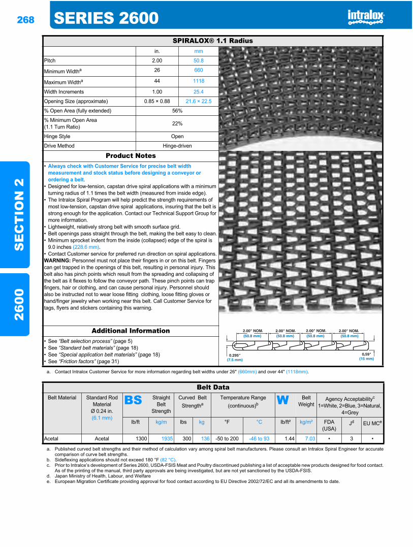
268 SERIES 2600S
EC
TIO
N 2
2600
SPIRALOX® 1.1 Radiusin. mm
Pitch 2.00 50.8
Minimum Widtha 26 660
Maximum Widtha 44 1118
Width Increments 1.00 25.4
Opening Size (approximate) 0.85 × 0.88 21.6 × 22.5
% Open Area (fully extended) 56%
% Minimum Open Area(1.1 Turn Ratio) 22%
Hinge Style Open
Drive Method Hinge-driven
Product Notes• Always check with Customer Service for precise belt width
measurement and stock status before designing a conveyor or ordering a belt.
• Designed for low-tension, capstan drive spiral applications with a minimum turning radius of 1.1 times the belt width (measured from inside edge).
• The Intralox Spiral Program will help predict the strength requirements of most low-tension, capstan drive spiral applications, insuring that the belt is strong enough for the application. Contact our Technical Support Group for more information.
• Lightweight, relatively strong belt with smooth surface grid.• Belt openings pass straight through the belt, making the belt easy to clean.• Minimum sprocket indent from the inside (collapsed) edge of the spiral is
9.0 inches (228.6 mm).• Contact Customer service for preferred run direction on spiral applications.WARNING: Personnel must not place their fingers in or on this belt. Fingers can get trapped in the openings of this belt, resulting in personal injury. This belt also has pinch points which result from the spreading and collapsing of the belt as it flexes to follow the conveyor path. These pinch points can trap fingers, hair or clothing, and can cause personal injury. Personnel should also be instructed not to wear loose fitting clothing, loose fitting gloves or hand/finger jewelry when working near this belt. Call Customer Service for tags, flyers and stickers containing this warning.
Additional Information• See “Belt selection process” (page 5)• See “Standard belt materials” (page 18)• See “Special application belt materials” (page 18)• See “Friction factors” (page 31)
a. Contact Intralox Customer Service for more information regarding belt widths under 26" (660mm) and over 44" (1118mm).
Belt DataBelt Material Standard Rod
MaterialØ 0.24 in. (6.1 mm)
BS Straight Belt
Strength
Curved Belt Strengtha
Temperature Range (continuous)b W Belt
WeightAgency Acceptabilityc
1=White, 2=Blue, 3=Natural, 4=Grey
lb/ft kg/m lbs kg °F °C lb/ft² kg/m² FDA (USA)
Jd EU MCe
Acetal Acetal 1300 1935 300 136 -50 to 200 -46 to 93 1.44 7.03 • 3 •
a. Published curved belt strengths and their method of calculation vary among spiral belt manufacturers. Please consult an Intralox Spiral Engineer for accuratecomparison of curve belt strengths.
b. Sideflexing applications should not exceed 180 °F (82 °C).c. Prior to Intralox’s development of Series 2600, USDA-FSIS Meat and Poultry discontinued publishing a list of acceptable new products designed for food contact.
As of the printing of the manual, third party approvals are being investigated, but are not yet sanctioned by the USDA-FSIS.d. Japan Ministry of Health, Labour, and Welfaree. European Migration Certificate providing approval for food contact according to EU Directive 2002/72/EC and all its amendments to date.
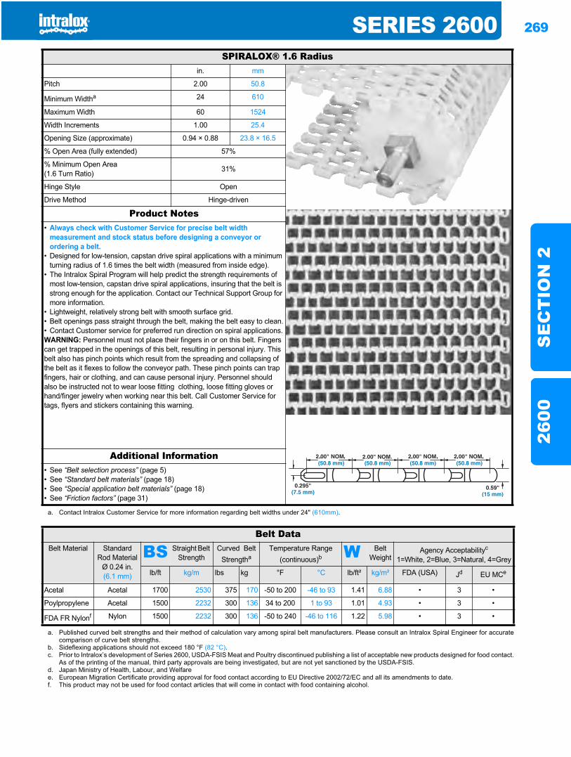
SERIES 2600 269
SE
CT
ION
226
00
SPIRALOX® 1.6 Radiusin. mm
Pitch 2.00 50.8
Minimum Widtha 24 610
Maximum Width 60 1524
Width Increments 1.00 25.4
Opening Size (approximate) 0.94 × 0.88 23.8 × 16.5
% Open Area (fully extended) 57%
% Minimum Open Area(1.6 Turn Ratio) 31%
Hinge Style Open
Drive Method Hinge-driven
Product Notes• Always check with Customer Service for precise belt width
measurement and stock status before designing a conveyor or ordering a belt.
• Designed for low-tension, capstan drive spiral applications with a minimum turning radius of 1.6 times the belt width (measured from inside edge).
• The Intralox Spiral Program will help predict the strength requirements of most low-tension, capstan drive spiral applications, insuring that the belt is strong enough for the application. Contact our Technical Support Group for more information.
• Lightweight, relatively strong belt with smooth surface grid.• Belt openings pass straight through the belt, making the belt easy to clean.• Contact Customer service for preferred run direction on spiral applications.WARNING: Personnel must not place their fingers in or on this belt. Fingers can get trapped in the openings of this belt, resulting in personal injury. This belt also has pinch points which result from the spreading and collapsing of the belt as it flexes to follow the conveyor path. These pinch points can trap fingers, hair or clothing, and can cause personal injury. Personnel should also be instructed not to wear loose fitting clothing, loose fitting gloves or hand/finger jewelry when working near this belt. Call Customer Service for tags, flyers and stickers containing this warning.
Additional Information• See “Belt selection process” (page 5)• See “Standard belt materials” (page 18)• See “Special application belt materials” (page 18)• See “Friction factors” (page 31)
a. Contact Intralox Customer Service for more information regarding belt widths under 24" (610mm).
Belt DataBelt Material Standard
Rod MaterialØ 0.24 in. (6.1 mm)
BS Straight Belt Strength
Curved Belt Strengtha
Temperature Range (continuous)b W Belt
WeightAgency Acceptabilityc
1=White, 2=Blue, 3=Natural, 4=Grey
lb/ft kg/m lbs kg °F °C lb/ft² kg/m² FDA (USA) Jd EU MCe
Acetal Acetal 1700 2530 375 170 -50 to 200 -46 to 93 1.41 6.88 • 3 •
Poylpropylene Acetal 1500 2232 300 136 34 to 200 1 to 93 1.01 4.93 • 3 •
FDA FR Nylonf Nylon 1500 2232 300 136 -50 to 240 -46 to 116 1.22 5.98 • 3 •
a. Published curved belt strengths and their method of calculation vary among spiral belt manufacturers. Please consult an Intralox Spiral Engineer for accuratecomparison of curve belt strengths.
b. Sideflexing applications should not exceed 180 °F (82 °C).c. Prior to Intralox’s development of Series 2600, USDA-FSIS Meat and Poultry discontinued publishing a list of acceptable new products designed for food contact.
As of the printing of the manual, third party approvals are being investigated, but are not yet sanctioned by the USDA-FSIS.d. Japan Ministry of Health, Labour, and Welfaree. European Migration Certificate providing approval for food contact according to EU Directive 2002/72/EC and all its amendments to date.f. This product may not be used for food contact articles that will come in contact with food containing alcohol.
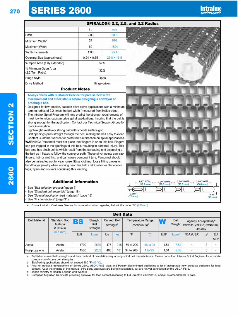
270 SERIES 2600S
EC
TIO
N 2
2600
SPIRALOX® 2.2, 2.5, and 3.2 Radiusin. mm
Pitch 2.00 50.8
Minimum Widtha 24 610
Maximum Width 60 1524
Width Increments 1.00 25.4
Opening Size (approximate) 0.94 × 0.65 23.8 × 16.5
% Open Area (fully extended) 57%
% Minimum Open Area(2.2 Turn Ratio) 32%
Hinge Style Open
Drive Method Hinge-driven
Product Notes• Always check with Customer Service for precise belt width
measurement and stock status before designing a conveyor or ordering a belt.
• Designed for low-tension, capstan drive spiral applications with a minimum turning radius of 2.2 times the belt width (measured from inside edge).
• The Intralox Spiral Program will help predict the strength requirements of most low-tension, capstan drive spiral applications, insuring that the belt is strong enough for the application. Contact our Technical Support Group for more information.
• Lightweight, relatively strong belt with smooth surface grid.• Belt openings pass straight through the belt, making the belt easy to clean.• Contact Customer service for preferred run direction on spiral applications.WARNING: Personnel must not place their fingers in or on this belt. Fingers can get trapped in the openings of this belt, resulting in personal injury. This belt also has pinch points which result from the spreading and collapsing of the belt as it flexes to follow the conveyor path. These pinch points can trap fingers, hair or clothing, and can cause personal injury. Personnel should also be instructed not to wear loose fitting clothing, loose fitting gloves or hand/finger jewelry when working near this belt. Call Customer Service for tags, flyers and stickers containing this warning.
Additional Information• See “Belt selection process” (page 5)• See “Standard belt materials” (page 18)• See “Special application belt materials” (page 18)• See “Friction factors” (page 31)
a. Contact Intralox Customer Service for more information regarding belt widths under 24" (610mm).
Belt DataBelt Material Standard Rod
MaterialØ 0.24 in. (6.1 mm)
BS Straight Belt
Strength
Curved Belt Strengtha
Temperature Range (continuous)b W Belt
WeightAgency Acceptabilityc
1=White, 2=Blue, 3=Natural, 4=Grey
lb/ft kg/m lbs kg °F °C lb/ft² kg/m² FDA (USA) Jd EU MCe
Acetal Acetal 1700 2530 475 215 -50 to 200 -46 to 93 1.54 7.52 • 3 •
Poylpropylene Acetal 1500 2232 400 181 34 to 200 1 to 93 1.04 5.08 • 3 •
a. Published curved belt strengths and their method of calculation vary among spiral belt manufacturers. Please consult an Intralox Spiral Engineer for accuratecomparison of curve belt strengths.
b. Sideflexing applications should not exceed 180 °F (82 °C).c. Prior to Intralox’s development of Series 2600, USDA-FSIS Meat and Poultry discontinued publishing a list of acceptable new products designed for food
contact. As of the printing of the manual, third party approvals are being investigated, but are not yet sanctioned by the USDA-FSIS.d. Japan Ministry of Health, Labour, and Welfaree. European Migration Certificate providing approval for food contact according to EU Directive 2002/72/EC and all its amendments to date.
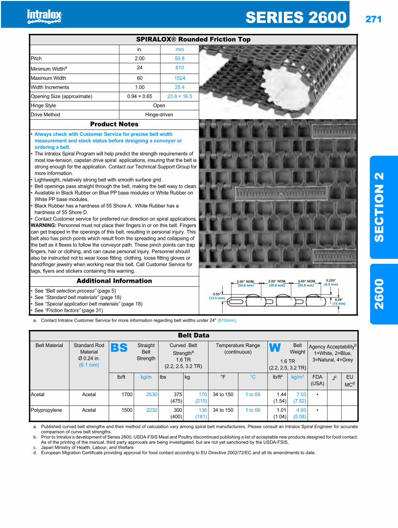
SERIES 2600 271
SE
CT
ION
226
00
SPIRALOX® Rounded Friction Topin. mm
Pitch 2.00 50.8
Minimum Widtha 24 610
Maximum Width 60 1524
Width Increments 1.00 25.4
Opening Size (approximate) 0.94 × 0.65 23.8 × 16.5
Hinge Style Open
Drive Method Hinge-driven
Product Notes• Always check with Customer Service for precise belt width
measurement and stock status before designing a conveyor or ordering a belt.
• The Intralox Spiral Program will help predict the strength requirements of most low-tension, capstan drive spiral applications, insuring that the belt is strong enough for the application. Contact our Technical Support Group for more information.
• Lightweight, relatively strong belt with smooth surface grid.• Belt openings pass straight through the belt, making the belt easy to clean.• Available in Black Rubber on Blue PP base modules or White Rubber on
White PP base modules.• Black Rubber has a hardness of 55 Shore A. White Rubber has a
hardness of 55 Shore D.• Contact Customer service for preferred run direction on spiral applications.WARNING: Personnel must not place their fingers in or on this belt. Fingers can get trapped in the openings of this belt, resulting in personal injury. This belt also has pinch points which result from the spreading and collapsing of the belt as it flexes to follow the conveyor path. These pinch points can trap fingers, hair or clothing, and can cause personal injury. Personnel should also be instructed not to wear loose fitting clothing, loose fitting gloves or hand/finger jewelry when working near this belt. Call Customer Service for tags, flyers and stickers containing this warning.
Additional Information• See “Belt selection process” (page 5)• See “Standard belt materials” (page 18)• See “Special application belt materials” (page 18)• See “Friction factors” (page 31)
a. Contact Intralox Customer Service for more information regarding belt widths under 24" (610mm).
Belt DataBelt Material Standard Rod
MaterialØ 0.24 in. (6.1 mm)
BS Straight Belt
Strength
Curved Belt Strengtha
1.6 TR(2.2, 2.5, 3.2 TR)
Temperature Range (continuous) W Belt
WeightAgency Acceptabilityb
1=White, 2=Blue, 3=Natural, 4=Grey1.6 TR
(2.2, 2.5, 3.2 TR)
lb/ft kg/m lbs kg °F °C lb/ft² kg/m² FDA (USA)
Jc EUMCd
Acetal Acetal 1700 2530 375(475)
170(215)
34 to 150 1 to 66 1.44(1.54)
7.03(7.52)
•
Polypropylene Acetal 1500 2232 300(400)
136(181)
34 to 150 1 to 66 1.01(1.04)
4.93(5.08)
•
a. Published curved belt strengths and their method of calculation vary among spiral belt manufacturers. Please consult an Intralox Spiral Engineer for accuratecomparison of curve belt strengths.
b. Prior to Intralox’s development of Series 2600, USDA-FSIS Meat and Poultry discontinued publishing a list of acceptable new products designed for food contact.As of the printing of the manual, third party approvals are being investigated, but are not yet sanctioned by the USDA-FSIS.
c. Japan Ministry of Health, Labour, and Welfared. European Migration Certificate providing approval for food contact according to EU Directive 2002/72/EC and all its amendments to date.
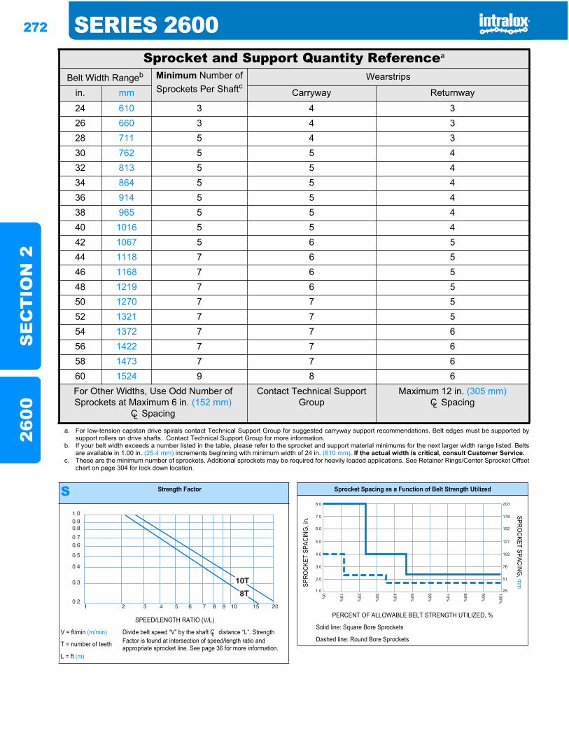
272 SERIES 2600S
EC
TIO
N 2
2600
Sprocket and Support Quantity Referencea
Belt Width Rangeb Minimum Number of Sprockets Per Shaftc
Wearstrips
in. mm Carryway Returnway
24 610 3 4 326 660 3 4 328 711 5 4 330 762 5 5 432 813 5 5 434 864 5 5 436 914 5 5 438 965 5 5 440 1016 5 5 442 1067 5 6 544 1118 7 6 546 1168 7 6 548 1219 7 6 550 1270 7 7 552 1321 7 7 554 1372 7 7 656 1422 7 7 658 1473 7 7 660 1524 9 8 6For Other Widths, Use Odd Number of Sprockets at Maximum 6 in. (152 mm)
CL Spacing
Contact Technical Support Group
Maximum 12 in. (305 mm)CL Spacing
a. For low-tension capstan drive spirals contact Technical Support Group for suggested carryway support recommendations. Belt edges must be supported bysupport rollers on drive shafts. Contact Technical Support Group for more information.
b. If your belt width exceeds a number listed in the table, please refer to the sprocket and support material minimums for the next larger width range listed. Beltsare available in 1.00 in. (25.4 mm) increments beginning with minimum width of 24 in. (610 mm). If the actual width is critical, consult Customer Service.
c. These are the minimum number of sprockets. Additional sprockets may be required for heavily loaded applications. See Retainer Rings/Center Sprocket Offsetchart on page 304 for lock down location.
S Strength Factor
SPEED/LENGTH RATIO (V/L)
V = ft/min (m/min) Divide belt speed “V” by the shaft CL distance “L”. Strength Factor is found at intersection of speed/length ratio and appropriate sprocket line. See page 36 for more information.T = number of teeth
L = ft (m)
Sprocket Spacing as a Function of Belt Strength Utilized
SPRO
CKET
SPA
CING
, in.
SPROCKET SPACING
, mm
PERCENT OF ALLOWABLE BELT STRENGTH UTILIZED, %
Solid line: Square Bore Sprockets
Dashed line: Round Bore Sprockets
100%
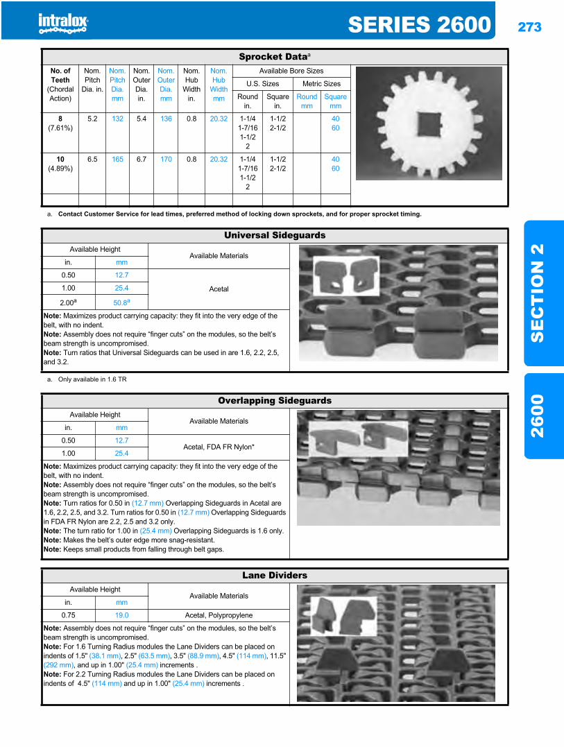
SERIES 2600 273
SE
CT
ION
226
00
Sprocket Dataa
No. of Teeth
(Chordal Action)
Nom. Pitch
Dia. in.
Nom. Pitch Dia. mm
Nom. Outer Dia.in.
Nom. Outer Dia.mm
Nom. Hub
Width in.
Nom. Hub
Width mm
Available Bore Sizes
U.S. Sizes Metric Sizes
Round in.
Square in.
Round mm
Square mm
8(7.61%)
5.2 132 5.4 136 0.8 20.32 1-1/41-7/161-1/2
2
1-1/22-1/2
4060
10(4.89%)
6.5 165 6.7 170 0.8 20.32 1-1/41-7/161-1/2
2
1-1/22-1/2
4060
a. Contact Customer Service for lead times, preferred method of locking down sprockets, and for proper sprocket timing.
Universal SideguardsAvailable Height
Available Materialsin. mm
0.50 12.7
Acetal1.00 25.4
2.00a 50.8a
Note: Maximizes product carrying capacity: they fit into the very edge of the belt, with no indent.Note: Assembly does not require “finger cuts” on the modules, so the belt’s beam strength is uncompromised.Note: Turn ratios that Universal Sideguards can be used in are 1.6, 2.2, 2.5, and 3.2.
a. Only available in 1.6 TR
Overlapping SideguardsAvailable Height
Available Materialsin. mm
0.50 12.7Acetal, FDA FR Nylon*
1.00 25.4
Note: Maximizes product carrying capacity: they fit into the very edge of the belt, with no indent.Note: Assembly does not require “finger cuts” on the modules, so the belt’s beam strength is uncompromised.Note: Turn ratios for 0.50 in (12.7 mm) Overlapping Sideguards in Acetal are 1.6, 2.2, 2.5, and 3.2. Turn ratios for 0.50 in (12.7 mm) Overlapping Sideguards in FDA FR Nylon are 2.2, 2.5 and 3.2 only.Note: The turn ratio for 1.00 in (25.4 mm) Overlapping Sideguards is 1.6 only.Note: Makes the belt’s outer edge more snag-resistant.Note: Keeps small products from falling through belt gaps.
Lane DividersAvailable Height
Available Materialsin. mm
0.75 19.0 Acetal, Polypropylene
Note: Assembly does not require “finger cuts” on the modules, so the belt’s beam strength is uncompromised.Note: For 1.6 Turning Radius modules the Lane Dividers can be placed on indents of 1.5" (38.1 mm), 2.5" (63.5 mm), 3.5" (88.9 mm), 4.5" (114 mm), 11.5" (292 mm), and up in 1.00" (25.4 mm) increments .Note: For 2.2 Turning Radius modules the Lane Dividers can be placed on indents of 4.5" (114 mm) and up in 1.00" (25.4 mm) increments .
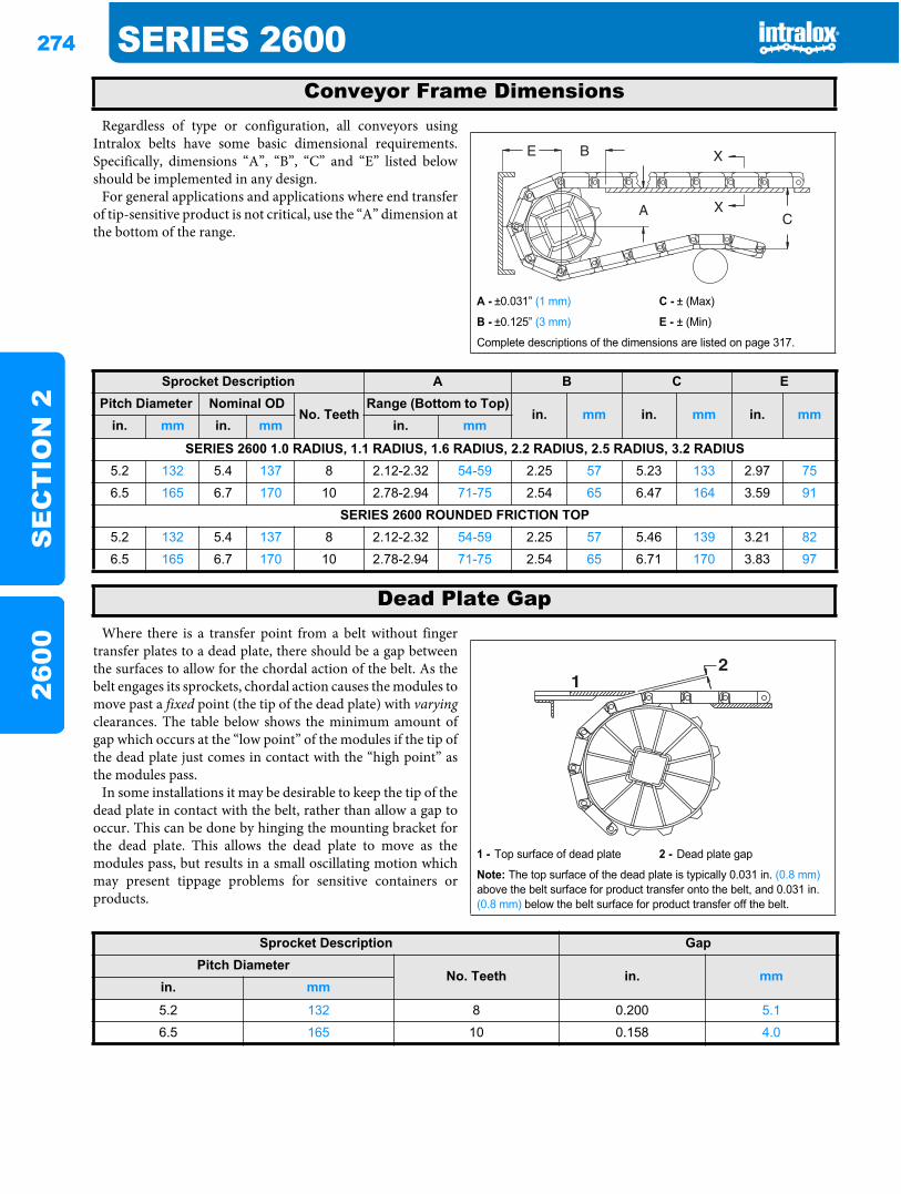
274 SERIES 2600S
EC
TIO
N 2
2600
Regardless of type or configuration, all conveyors usingIntralox belts have some basic dimensional requirements.Specifically, dimensions “A”, “B”, “C” and “E” listed belowshould be implemented in any design.
For general applications and applications where end transferof tip-sensitive product is not critical, use the “A” dimension atthe bottom of the range.
Where there is a transfer point from a belt without fingertransfer plates to a dead plate, there should be a gap betweenthe surfaces to allow for the chordal action of the belt. As thebelt engages its sprockets, chordal action causes the modules tomove past a fixed point (the tip of the dead plate) with varyingclearances. The table below shows the minimum amount ofgap which occurs at the “low point” of the modules if the tip ofthe dead plate just comes in contact with the “high point” asthe modules pass.
In some installations it may be desirable to keep the tip of thedead plate in contact with the belt, rather than allow a gap tooccur. This can be done by hinging the mounting bracket forthe dead plate. This allows the dead plate to move as themodules pass, but results in a small oscillating motion whichmay present tippage problems for sensitive containers orproducts.
Conveyor Frame Dimensions
A - ±0.031” (1 mm) C - ± (Max)
B - ±0.125” (3 mm) E - ± (Min)
Complete descriptions of the dimensions are listed on page 317.
Sprocket Description A B C EPitch Diameter Nominal OD
No. TeethRange (Bottom to Top)
in. mm in. mm in. mmin. mm in. mm in. mm
SERIES 2600 1.0 RADIUS, 1.1 RADIUS, 1.6 RADIUS, 2.2 RADIUS, 2.5 RADIUS, 3.2 RADIUS5.2 132 5.4 137 8 2.12-2.32 54-59 2.25 57 5.23 133 2.97 75
6.5 165 6.7 170 10 2.78-2.94 71-75 2.54 65 6.47 164 3.59 91
SERIES 2600 ROUNDED FRICTION TOP5.2 132 5.4 137 8 2.12-2.32 54-59 2.25 57 5.46 139 3.21 82
6.5 165 6.7 170 10 2.78-2.94 71-75 2.54 65 6.71 170 3.83 97
Dead Plate Gap
1 - Top surface of dead plate 2 - Dead plate gap
Note: The top surface of the dead plate is typically 0.031 in. (0.8 mm)above the belt surface for product transfer onto the belt, and 0.031 in. (0.8 mm) below the belt surface for product transfer off the belt.
21
Sprocket Description GapPitch Diameter
No. Teeth in. mmin. mm
5.2 132 8 0.200 5.1
6.5 165 10 0.158 4.0
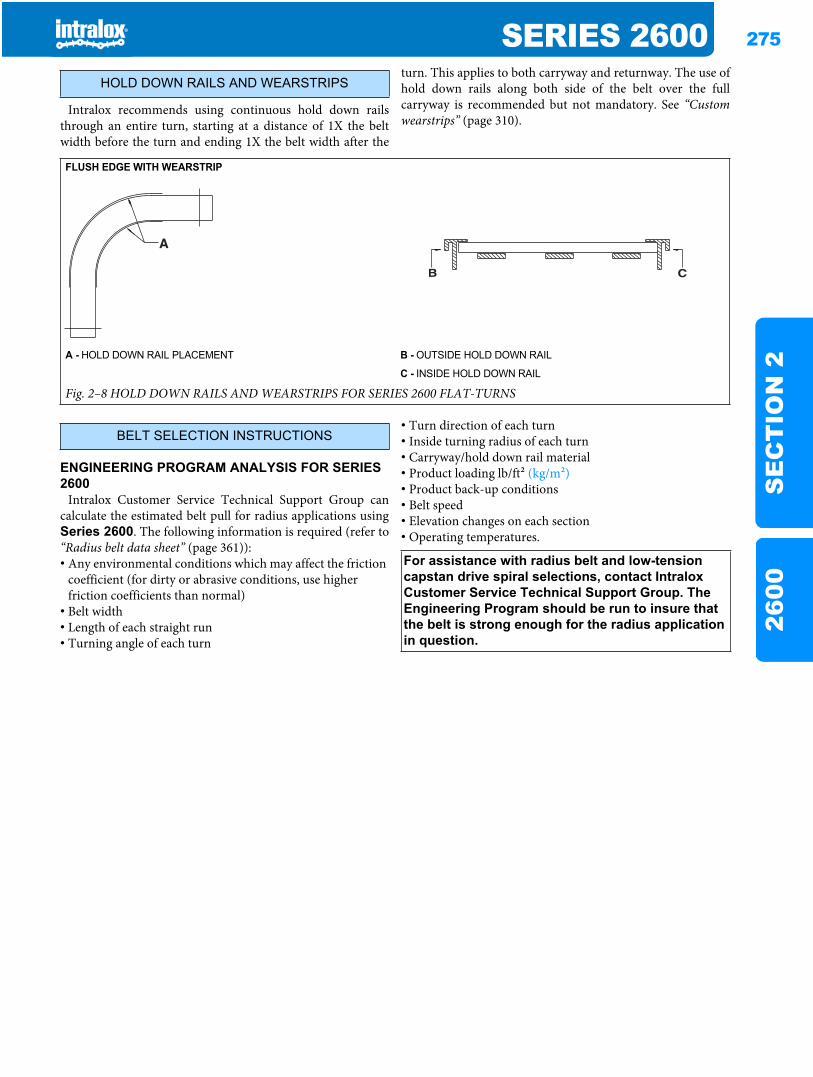
SERIES 2600 275
SE
CT
ION
226
00
Intralox recommends using continuous hold down railsthrough an entire turn, starting at a distance of 1X the beltwidth before the turn and ending 1X the belt width after the
turn. This applies to both carryway and returnway. The use ofhold down rails along both side of the belt over the fullcarryway is recommended but not mandatory. See “Customwearstrips” (page 310).
ENGINEERING PROGRAM ANALYSIS FOR SERIES 2600
Intralox Customer Service Technical Support Group cancalculate the estimated belt pull for radius applications usingSeries 2600. The following information is required (refer to“Radius belt data sheet” (page 361)):• Any environmental conditions which may affect the friction
coefficient (for dirty or abrasive conditions, use higher friction coefficients than normal)
• Belt width• Length of each straight run• Turning angle of each turn
• Turn direction of each turn• Inside turning radius of each turn• Carryway/hold down rail material• Product loading lb/ft2 (kg/m2)• Product back-up conditions• Belt speed• Elevation changes on each section• Operating temperatures.
HOLD DOWN RAILS AND WEARSTRIPS
FLUSH EDGE WITH WEARSTRIP
A - HOLD DOWN RAIL PLACEMENT B - OUTSIDE HOLD DOWN RAIL
C - INSIDE HOLD DOWN RAIL
Fig. 2–8 HOLD DOWN RAILS AND WEARSTRIPS FOR SERIES 2600 FLAT-TURNS
BELT SELECTION INSTRUCTIONS
For assistance with radius belt and low-tension capstan drive spiral selections, contact Intralox Customer Service Technical Support Group. The Engineering Program should be run to insure that the belt is strong enough for the radius application in question.

276 SERIES 2600S
EC
TIO
N 2
2600
SERIES 2600 DESIGN GUIDE SUMMARYFor more information, see the Installation, Maintenance and Toubleshooting manual available from Intralox.
E - The minimum length of the first straight run (immediately after the idle shaft) is 1.5 times the belt width. When shorter lengths are required (down to 1.0 times the width), an idle roller may be used in place of sprockets.
A - The minimum turning radius for Series 2600 is the turning radius times the belt width, measured from the inside edge.
F - IDLE SHAFT
G - 1ST TURN
B - The minimum straight run required between turns of opposing direction is 2.0 times the belt width. Shorter straight sections will lead to high wear on the edge guide rail and high pull stresses in the belt.
H - BELT WIDTH
I - BELT TRAVEL
J - 2ND TURN
C - There is no minimum straight run required between turns that are in the same direction.
K - DRIVE MOTOR
D - The minimum length for the final straight run (leading into the drive shaft) is 1.5 times the belt width. Shorter lengths may lead to sprocket wear or tracking problems. For narrow belts, a weighted take-up may be required since proper catenary cannot be achieved therefore, a 5 ft. (1.50 m) minimum final straight run is recommended. See “Special Take-Up Arrangements” (page 324).
L - DRIVE SHAFT
Fig. 2–9 TYPICAL 2-TURN RADIUS LAYOUT
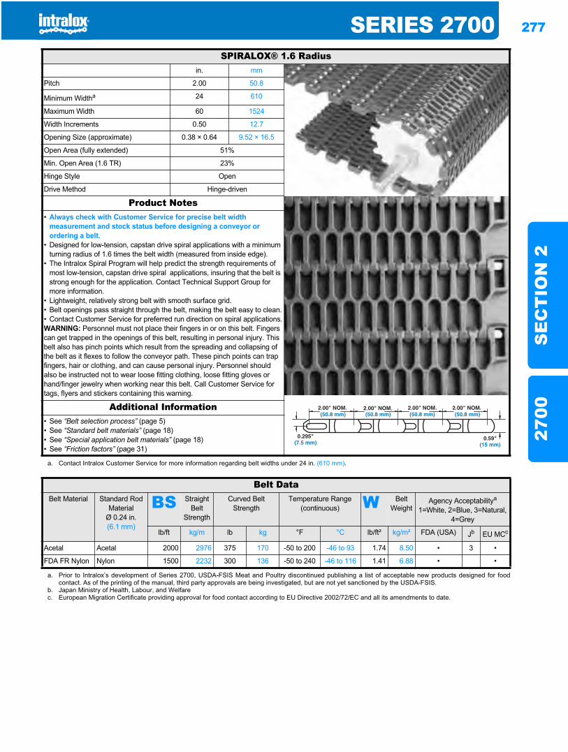
SERIES 2700 277
SE
CT
ION
227
00
Series 27002700
SPIRALOX® 1.6 Radiusin. mm
Pitch 2.00 50.8
Minimum Widtha 24 610
Maximum Width 60 1524
Width Increments 0.50 12.7
Opening Size (approximate) 0.38 × 0.64 9.52 × 16.5
Open Area (fully extended) 51%
Min. Open Area (1.6 TR) 23%
Hinge Style Open
Drive Method Hinge-driven
Product Notes• Always check with Customer Service for precise belt width
measurement and stock status before designing a conveyor or ordering a belt.
• Designed for low-tension, capstan drive spiral applications with a minimum turning radius of 1.6 times the belt width (measured from inside edge).
• The Intralox Spiral Program will help predict the strength requirements of most low-tension, capstan drive spiral applications, insuring that the belt is strong enough for the application. Contact Technical Support Group for more information.
• Lightweight, relatively strong belt with smooth surface grid.• Belt openings pass straight through the belt, making the belt easy to clean.• Contact Customer Service for preferred run direction on spiral applications.WARNING: Personnel must not place their fingers in or on this belt. Fingers can get trapped in the openings of this belt, resulting in personal injury. This belt also has pinch points which result from the spreading and collapsing of the belt as it flexes to follow the conveyor path. These pinch points can trap fingers, hair or clothing, and can cause personal injury. Personnel should also be instructed not to wear loose fitting clothing, loose fitting gloves or hand/finger jewelry when working near this belt. Call Customer Service for tags, flyers and stickers containing this warning.
Additional Information• See “Belt selection process” (page 5)• See “Standard belt materials” (page 18)• See “Special application belt materials” (page 18)• See “Friction factors” (page 31)
a. Contact Intralox Customer Service for more information regarding belt widths under 24 in. (610 mm).
Belt DataBelt Material Standard Rod
MaterialØ 0.24 in. (6.1 mm)
BS Straight Belt
Strength
Curved Belt Strength
Temperature Range (continuous) W Belt
WeightAgency Acceptabilitya
1=White, 2=Blue, 3=Natural, 4=Grey
lb/ft kg/m lb kg °F °C lb/ft² kg/m² FDA (USA) Jb EU MCc
Acetal Acetal 2000 2976 375 170 -50 to 200 -46 to 93 1.74 8.50 • 3 •
FDA FR Nylon Nylon 1500 2232 300 136 -50 to 240 -46 to 116 1.41 6.88 • •
a. Prior to Intralox’s development of Series 2700, USDA-FSIS Meat and Poultry discontinued publishing a list of acceptable new products designed for foodcontact. As of the printing of the manual, third party approvals are being investigated, but are not yet sanctioned by the USDA-FSIS.
b. Japan Ministry of Health, Labour, and Welfarec. European Migration Certificate providing approval for food contact according to EU Directive 2002/72/EC and all its amendments to date.
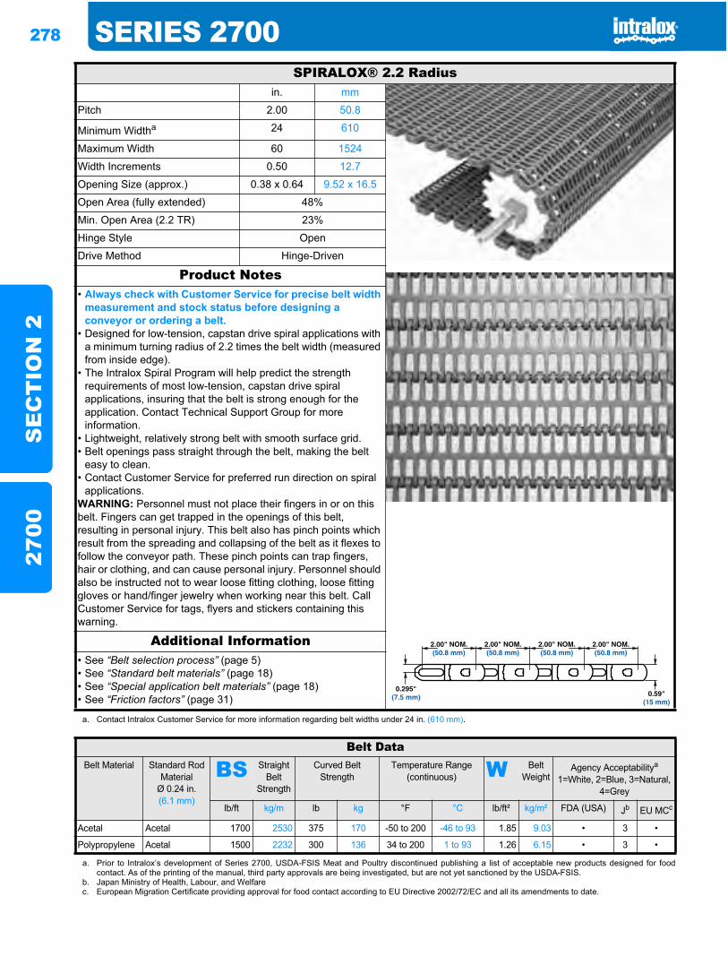
278 SERIES 2700S
EC
TIO
N 2
2700
SPIRALOX® 2.2 Radiusin. mm
Pitch 2.00 50.8
Minimum Widtha 24 610
Maximum Width 60 1524
Width Increments 0.50 12.7
Opening Size (approx.) 0.38 x 0.64 9.52 x 16.5
Open Area (fully extended) 48%
Min. Open Area (2.2 TR) 23%
Hinge Style Open
Drive Method Hinge-Driven
Product Notes• Always check with Customer Service for precise belt width
measurement and stock status before designing a conveyor or ordering a belt.
• Designed for low-tension, capstan drive spiral applications with a minimum turning radius of 2.2 times the belt width (measured from inside edge).
• The Intralox Spiral Program will help predict the strength requirements of most low-tension, capstan drive spiral applications, insuring that the belt is strong enough for the application. Contact Technical Support Group for more information.
• Lightweight, relatively strong belt with smooth surface grid.• Belt openings pass straight through the belt, making the belt
easy to clean.• Contact Customer Service for preferred run direction on spiral
applications.WARNING: Personnel must not place their fingers in or on this belt. Fingers can get trapped in the openings of this belt, resulting in personal injury. This belt also has pinch points which result from the spreading and collapsing of the belt as it flexes to follow the conveyor path. These pinch points can trap fingers, hair or clothing, and can cause personal injury. Personnel should also be instructed not to wear loose fitting clothing, loose fitting gloves or hand/finger jewelry when working near this belt. Call Customer Service for tags, flyers and stickers containing this warning.
Additional Information• See “Belt selection process” (page 5)• See “Standard belt materials” (page 18)• See “Special application belt materials” (page 18)• See “Friction factors” (page 31)
a. Contact Intralox Customer Service for more information regarding belt widths under 24 in. (610 mm).
Belt DataBelt Material Standard Rod
MaterialØ 0.24 in. (6.1 mm)
BS Straight Belt
Strength
Curved Belt Strength
Temperature Range (continuous) W Belt
WeightAgency Acceptabilitya
1=White, 2=Blue, 3=Natural, 4=Grey
lb/ft kg/m lb kg °F °C lb/ft² kg/m² FDA (USA) Jb EU MCc
Acetal Acetal 1700 2530 375 170 -50 to 200 -46 to 93 1.85 9.03 • 3 •
Polypropylene Acetal 1500 2232 300 136 34 to 200 1 to 93 1.26 6.15 • 3 •
a. Prior to Intralox’s development of Series 2700, USDA-FSIS Meat and Poultry discontinued publishing a list of acceptable new products designed for foodcontact. As of the printing of the manual, third party approvals are being investigated, but are not yet sanctioned by the USDA-FSIS.
b. Japan Ministry of Health, Labour, and Welfarec. European Migration Certificate providing approval for food contact according to EU Directive 2002/72/EC and all its amendments to date.
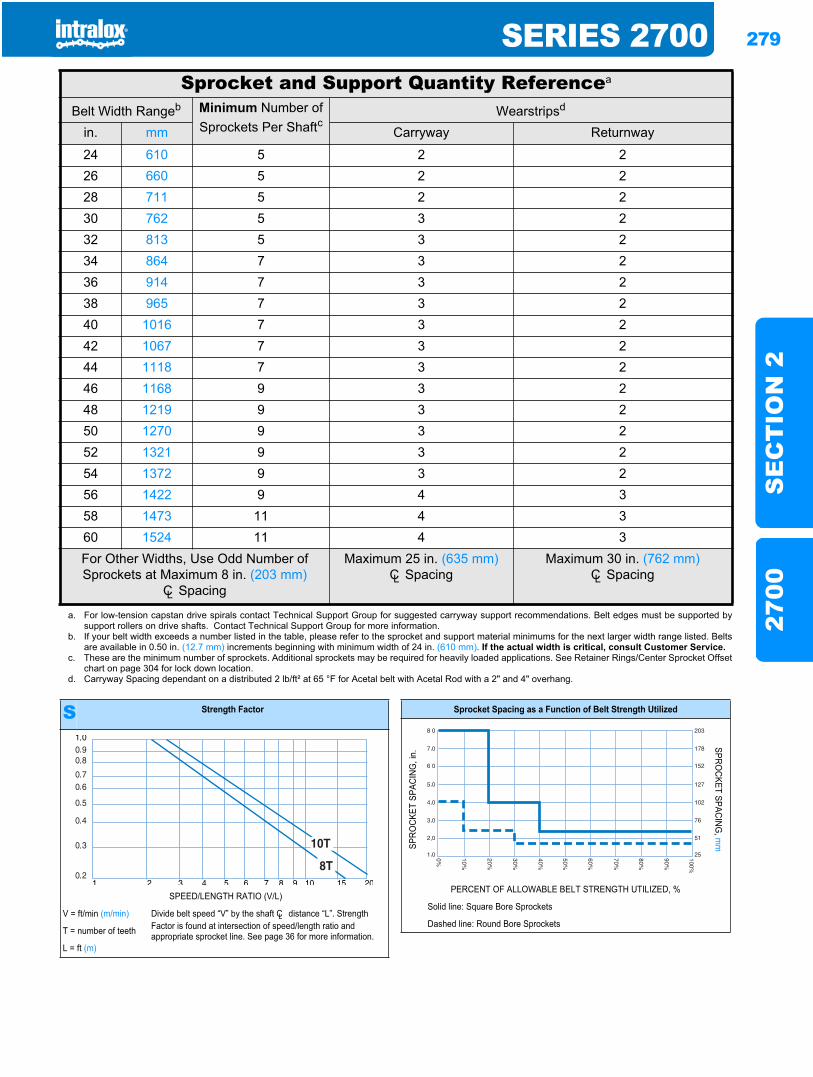
SERIES 2700 279
SE
CT
ION
227
00
Sprocket and Support Quantity Referencea
Belt Width Rangeb Minimum Number of Sprockets Per Shaftc
Wearstripsd
in. mm Carryway Returnway
24 610 5 2 226 660 5 2 228 711 5 2 230 762 5 3 232 813 5 3 234 864 7 3 236 914 7 3 238 965 7 3 240 1016 7 3 242 1067 7 3 244 1118 7 3 246 1168 9 3 248 1219 9 3 250 1270 9 3 252 1321 9 3 254 1372 9 3 256 1422 9 4 358 1473 11 4 360 1524 11 4 3For Other Widths, Use Odd Number of Sprockets at Maximum 8 in. (203 mm)
CL Spacing
Maximum 25 in. (635 mm)CL Spacing
Maximum 30 in. (762 mm)CL Spacing
a. For low-tension capstan drive spirals contact Technical Support Group for suggested carryway support recommendations. Belt edges must be supported bysupport rollers on drive shafts. Contact Technical Support Group for more information.
b. If your belt width exceeds a number listed in the table, please refer to the sprocket and support material minimums for the next larger width range listed. Beltsare available in 0.50 in. (12.7 mm) increments beginning with minimum width of 24 in. (610 mm). If the actual width is critical, consult Customer Service.
c. These are the minimum number of sprockets. Additional sprockets may be required for heavily loaded applications. See Retainer Rings/Center Sprocket Offsetchart on page 304 for lock down location.
d. Carryway Spacing dependant on a distributed 2 lb/ft² at 65 °F for Acetal belt with Acetal Rod with a 2" and 4" overhang.
S Strength Factor
SPEED/LENGTH RATIO (V/L)
V = ft/min (m/min) Divide belt speed “V” by the shaft CL distance “L”. Strength Factor is found at intersection of speed/length ratio and appropriate sprocket line. See page 36 for more information.T = number of teeth
L = ft (m)
Sprocket Spacing as a Function of Belt Strength Utilized
SPRO
CKET
SPA
CING
, in.
SPROCKET SPACING
, mm
PERCENT OF ALLOWABLE BELT STRENGTH UTILIZED, %
Solid line: Square Bore Sprockets
Dashed line: Round Bore Sprockets
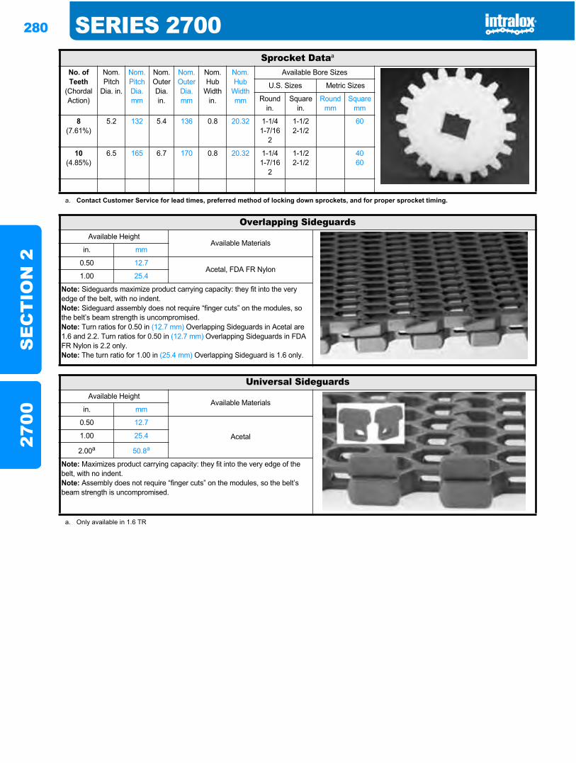
280 SERIES 2700S
EC
TIO
N 2
2700
Sprocket Dataa
No. of Teeth
(Chordal Action)
Nom. Pitch
Dia. in.
Nom. Pitch Dia. mm
Nom. Outer Dia.in.
Nom. Outer Dia.mm
Nom. Hub
Width in.
Nom. Hub
Width mm
Available Bore Sizes
U.S. Sizes Metric Sizes
Round in.
Square in.
Round mm
Square mm
8(7.61%)
5.2 132 5.4 136 0.8 20.32 1-1/41-7/16
2
1-1/22-1/2
60
10(4.85%)
6.5 165 6.7 170 0.8 20.32 1-1/41-7/16
2
1-1/22-1/2
4060
a. Contact Customer Service for lead times, preferred method of locking down sprockets, and for proper sprocket timing.
Overlapping SideguardsAvailable Height
Available Materialsin. mm
0.50 12.7Acetal, FDA FR Nylon
1.00 25.4
Note: Sideguards maximize product carrying capacity: they fit into the very edge of the belt, with no indent.Note: Sideguard assembly does not require “finger cuts” on the modules, so the belt’s beam strength is uncompromised.Note: Turn ratios for 0.50 in (12.7 mm) Overlapping Sideguards in Acetal are 1.6 and 2.2. Turn ratios for 0.50 in (12.7 mm) Overlapping Sideguards in FDA FR Nylon is 2.2 only.Note: The turn ratio for 1.00 in (25.4 mm) Overlapping Sideguard is 1.6 only.
Universal SideguardsAvailable Height
Available Materialsin. mm
0.50 12.7
Acetal1.00 25.4
2.00a 50.8a
Note: Maximizes product carrying capacity: they fit into the very edge of the belt, with no indent.Note: Assembly does not require “finger cuts” on the modules, so the belt’s beam strength is uncompromised.
a. Only available in 1.6 TR
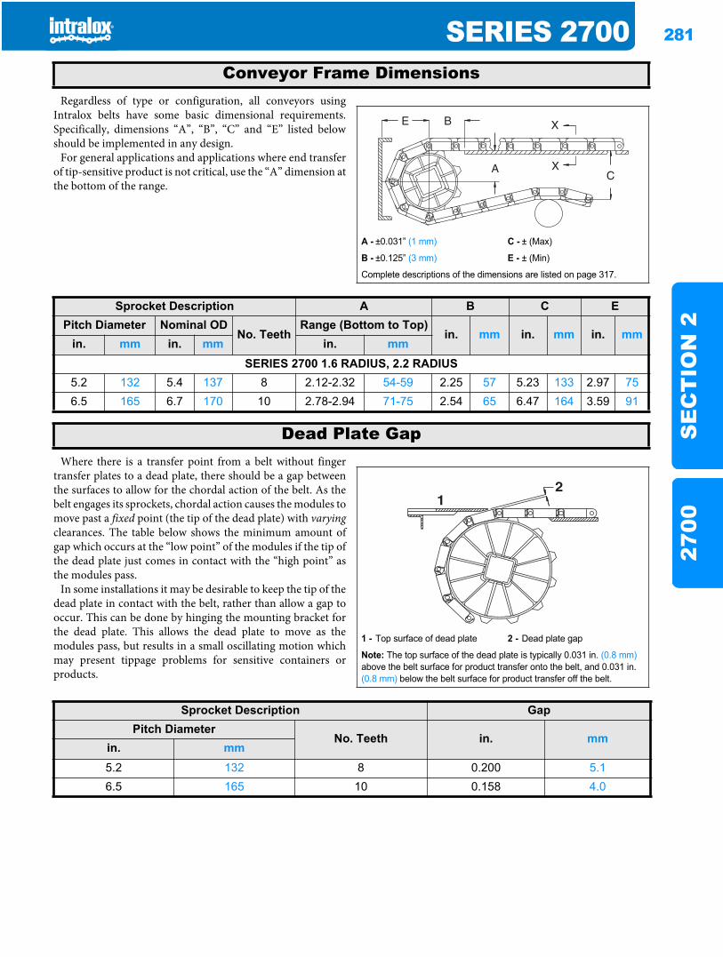
SERIES 2700 281
SE
CT
ION
227
00
Regardless of type or configuration, all conveyors usingIntralox belts have some basic dimensional requirements.Specifically, dimensions “A”, “B”, “C” and “E” listed belowshould be implemented in any design.
For general applications and applications where end transferof tip-sensitive product is not critical, use the “A” dimension atthe bottom of the range.
Where there is a transfer point from a belt without fingertransfer plates to a dead plate, there should be a gap betweenthe surfaces to allow for the chordal action of the belt. As thebelt engages its sprockets, chordal action causes the modules tomove past a fixed point (the tip of the dead plate) with varyingclearances. The table below shows the minimum amount ofgap which occurs at the “low point” of the modules if the tip ofthe dead plate just comes in contact with the “high point” asthe modules pass.
In some installations it may be desirable to keep the tip of thedead plate in contact with the belt, rather than allow a gap tooccur. This can be done by hinging the mounting bracket forthe dead plate. This allows the dead plate to move as themodules pass, but results in a small oscillating motion whichmay present tippage problems for sensitive containers orproducts.
Conveyor Frame Dimensions
A - ±0.031” (1 mm) C - ± (Max)
B - ±0.125” (3 mm) E - ± (Min)
Complete descriptions of the dimensions are listed on page 317.
Sprocket Description A B C EPitch Diameter Nominal OD
No. TeethRange (Bottom to Top)
in. mm in. mm in. mmin. mm in. mm in. mm
SERIES 2700 1.6 RADIUS, 2.2 RADIUS5.2 132 5.4 137 8 2.12-2.32 54-59 2.25 57 5.23 133 2.97 756.5 165 6.7 170 10 2.78-2.94 71-75 2.54 65 6.47 164 3.59 91
Dead Plate Gap
1 - Top surface of dead plate 2 - Dead plate gap
Note: The top surface of the dead plate is typically 0.031 in. (0.8 mm)above the belt surface for product transfer onto the belt, and 0.031 in. (0.8 mm) below the belt surface for product transfer off the belt.
21
Sprocket Description GapPitch Diameter
No. Teeth in. mmin. mm5.2 132 8 0.200 5.16.5 165 10 0.158 4.0
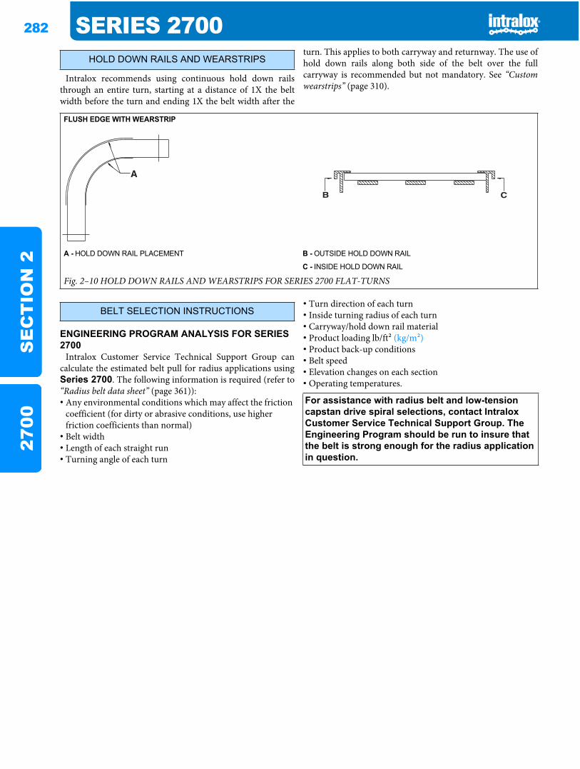
282 SERIES 2700S
EC
TIO
N 2
2700
Intralox recommends using continuous hold down railsthrough an entire turn, starting at a distance of 1X the beltwidth before the turn and ending 1X the belt width after the
turn. This applies to both carryway and returnway. The use ofhold down rails along both side of the belt over the fullcarryway is recommended but not mandatory. See “Customwearstrips” (page 310).
ENGINEERING PROGRAM ANALYSIS FOR SERIES 2700
Intralox Customer Service Technical Support Group cancalculate the estimated belt pull for radius applications usingSeries 2700. The following information is required (refer to“Radius belt data sheet” (page 361)):• Any environmental conditions which may affect the friction
coefficient (for dirty or abrasive conditions, use higher friction coefficients than normal)
• Belt width• Length of each straight run• Turning angle of each turn
• Turn direction of each turn• Inside turning radius of each turn• Carryway/hold down rail material• Product loading lb/ft2 (kg/m2)• Product back-up conditions• Belt speed• Elevation changes on each section• Operating temperatures.
HOLD DOWN RAILS AND WEARSTRIPS
FLUSH EDGE WITH WEARSTRIP
A - HOLD DOWN RAIL PLACEMENT B - OUTSIDE HOLD DOWN RAIL
C - INSIDE HOLD DOWN RAIL
Fig. 2–10 HOLD DOWN RAILS AND WEARSTRIPS FOR SERIES 2700 FLAT-TURNS
BELT SELECTION INSTRUCTIONS
For assistance with radius belt and low-tension capstan drive spiral selections, contact Intralox Customer Service Technical Support Group. The Engineering Program should be run to insure that the belt is strong enough for the radius application in question.
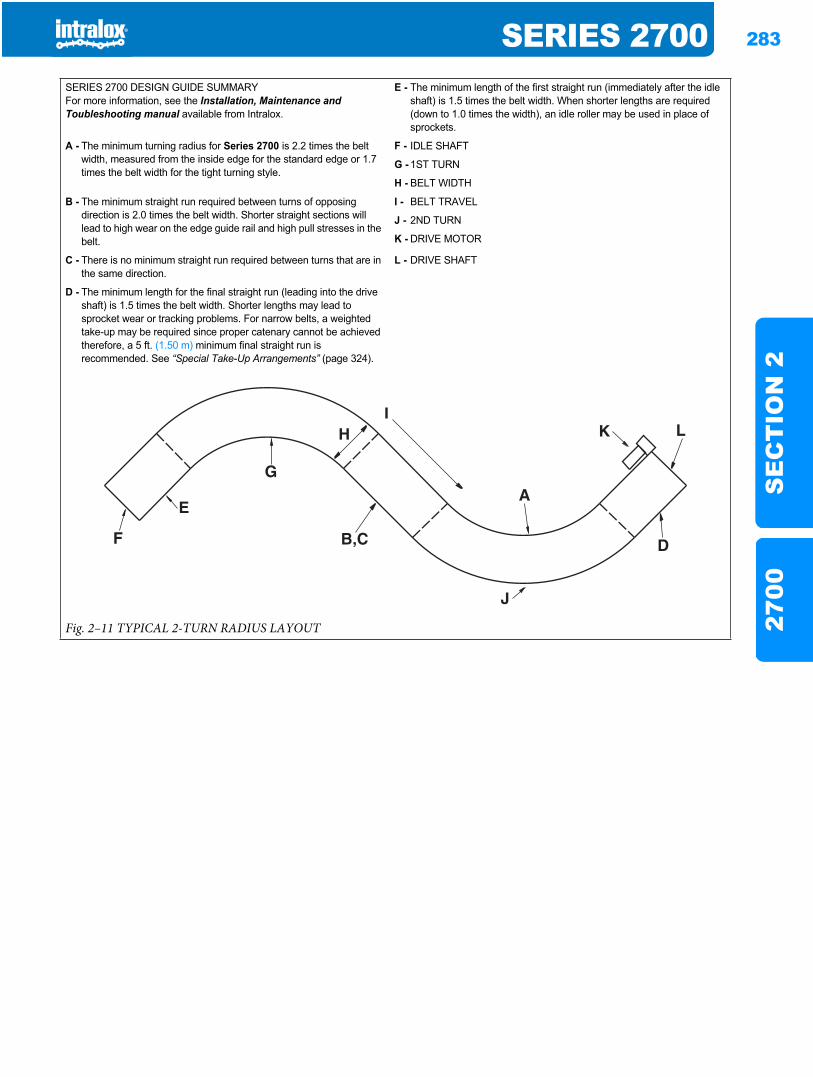
SERIES 2700 283
SE
CT
ION
227
00
SERIES 2700 DESIGN GUIDE SUMMARYFor more information, see the Installation, Maintenance and Toubleshooting manual available from Intralox.
E - The minimum length of the first straight run (immediately after the idle shaft) is 1.5 times the belt width. When shorter lengths are required (down to 1.0 times the width), an idle roller may be used in place of sprockets.
A - The minimum turning radius for Series 2700 is 2.2 times the belt width, measured from the inside edge for the standard edge or 1.7 times the belt width for the tight turning style.
F - IDLE SHAFT
G - 1ST TURN
H - BELT WIDTH
B - The minimum straight run required between turns of opposing direction is 2.0 times the belt width. Shorter straight sections will lead to high wear on the edge guide rail and high pull stresses in the belt.
I - BELT TRAVEL
J - 2ND TURN
K - DRIVE MOTOR
C - There is no minimum straight run required between turns that are in the same direction.
L - DRIVE SHAFT
D - The minimum length for the final straight run (leading into the drive shaft) is 1.5 times the belt width. Shorter lengths may lead to sprocket wear or tracking problems. For narrow belts, a weighted take-up may be required since proper catenary cannot be achieved therefore, a 5 ft. (1.50 m) minimum final straight run is recommended. See “Special Take-Up Arrangements” (page 324).
Fig. 2–11 TYPICAL 2-TURN RADIUS LAYOUT

284 SERIES 2700S
EC
TIO
N 2
2700
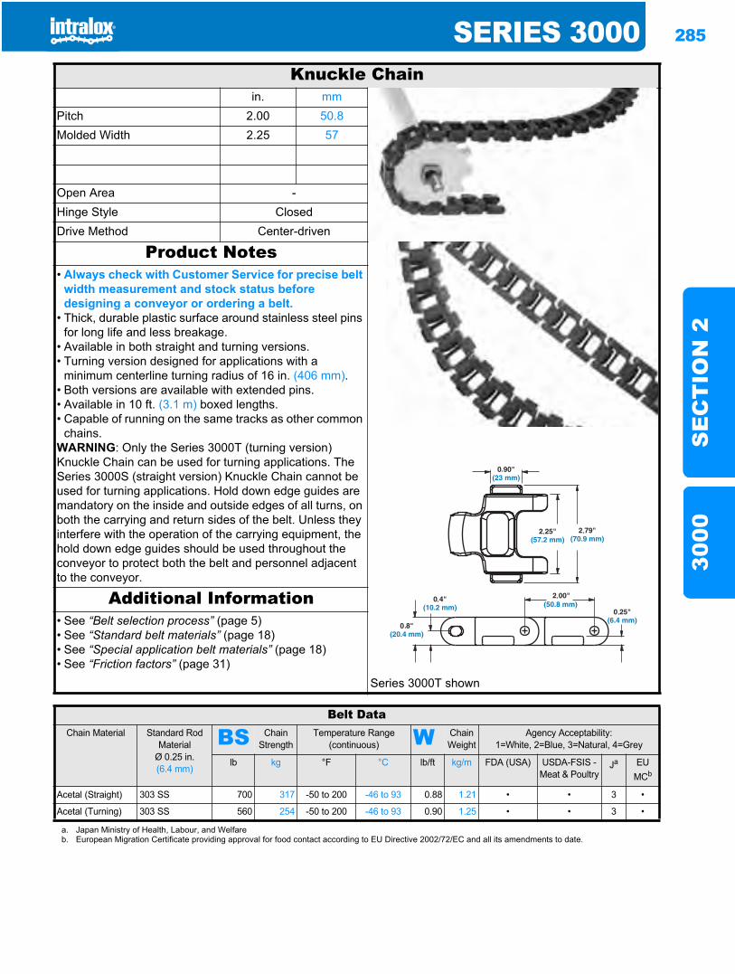
SERIES 3000 285
SE
CT
ION
230
00
Series 30003000
Knuckle Chainin. mm
Pitch 2.00 50.8Molded Width 2.25 57
Open Area -Hinge Style ClosedDrive Method Center-driven
Product Notes• Always check with Customer Service for precise belt
width measurement and stock status before designing a conveyor or ordering a belt.
• Thick, durable plastic surface around stainless steel pins for long life and less breakage.
• Available in both straight and turning versions.• Turning version designed for applications with a
minimum centerline turning radius of 16 in. (406 mm).• Both versions are available with extended pins.• Available in 10 ft. (3.1 m) boxed lengths.• Capable of running on the same tracks as other common
chains.WARNING: Only the Series 3000T (turning version) Knuckle Chain can be used for turning applications. The Series 3000S (straight version) Knuckle Chain cannot be used for turning applications. Hold down edge guides are mandatory on the inside and outside edges of all turns, on both the carrying and return sides of the belt. Unless they interfere with the operation of the carrying equipment, the hold down edge guides should be used throughout the conveyor to protect both the belt and personnel adjacent to the conveyor.
Additional Information• See “Belt selection process” (page 5)• See “Standard belt materials” (page 18)• See “Special application belt materials” (page 18)• See “Friction factors” (page 31)
Series 3000T shown
Belt DataChain Material Standard Rod
MaterialØ 0.25 in. (6.4 mm)
BS Chain Strength
Temperature Range (continuous) W Chain
WeightAgency Acceptability:
1=White, 2=Blue, 3=Natural, 4=Grey
lb kg °F °C lb/ft kg/m FDA (USA) USDA-FSIS - Meat & Poultry
Ja EUMCb
Acetal (Straight) 303 SS 700 317 -50 to 200 -46 to 93 0.88 1.21 • • 3 •
Acetal (Turning) 303 SS 560 254 -50 to 200 -46 to 93 0.90 1.25 • • 3 •
a. Japan Ministry of Health, Labour, and Welfareb. European Migration Certificate providing approval for food contact according to EU Directive 2002/72/EC and all its amendments to date.
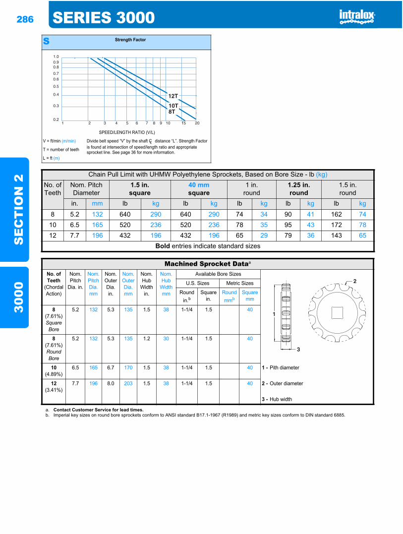
286 SERIES 3000S
EC
TIO
N 2
3000
S Strength Factor
SPEED/LENGTH RATIO (V/L)
V = ft/min (m/min) Divide belt speed “V” by the shaft CL distance “L”. Strength Factor is found at intersection of speed/length ratio and appropriate sprocket line. See page 36 for more information.T = number of teeth
L = ft (m)
1.00.90.8
0.70.6
0.5
0.4
0.3
0.21 2 3 4 5 6 7 8 9 10 15 20
Chain Pull Limit with UHMW Polyethylene Sprockets, Based on Bore Size - lb (kg)No. ofTeeth
Nom. Pitch Diameter
1.5 in.square
40 mmsquare
1 in.round
1.25 in.round
1.5 in.round
in. mm lb kg lb kg lb kg lb kg lb kg
8 5.2 132 640 290 640 290 74 34 90 41 162 7410 6.5 165 520 236 520 236 78 35 95 43 172 7812 7.7 196 432 196 432 196 65 29 79 36 143 65
Bold entries indicate standard sizes
Machined Sprocket Dataa
No. of Teeth
(Chordal Action)
Nom. Pitch
Dia. in.
Nom. Pitch Dia. mm
Nom. Outer Dia.in.
Nom. Outer Dia.mm
Nom. Hub
Width in.
Nom. Hub
Width mm
Available Bore Sizes
U.S. Sizes Metric Sizes
Round in.b
Square in.
Round mmb
Square mm
8(7.61%)Square Bore
5.2 132 5.3 135 1.5 38 1-1/4 1.5 40
8(7.61%)Round Bore
5.2 132 5.3 135 1.2 30 1-1/4 1.5 40
10(4.89%)
6.5 165 6.7 170 1.5 38 1-1/4 1.5 40 1 - Pith diameter
12(3.41%)
7.7 196 8.0 203 1.5 38 1-1/4 1.5 40 2 - Outer diameter
3 - Hub width
a. Contact Customer Service for lead times.b. Imperial key sizes on round bore sprockets conform to ANSI standard B17.1-1967 (R1989) and metric key sizes conform to DIN standard 6885.
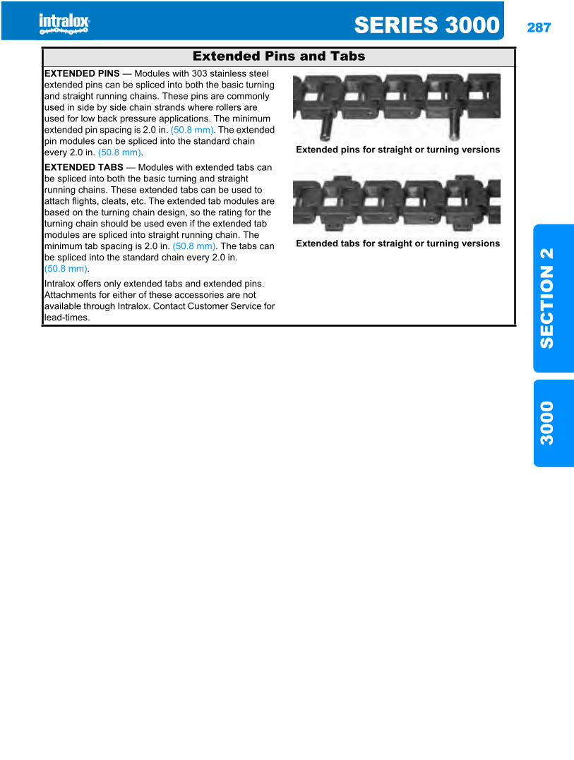
SERIES 3000 287
SE
CT
ION
230
00
Extended Pins and TabsEXTENDED PINS — Modules with 303 stainless steel extended pins can be spliced into both the basic turning and straight running chains. These pins are commonly used in side by side chain strands where rollers are used for low back pressure applications. The minimum extended pin spacing is 2.0 in. (50.8 mm). The extended pin modules can be spliced into the standard chain every 2.0 in. (50.8 mm). Extended pins for straight or turning versions
EXTENDED TABS — Modules with extended tabs can be spliced into both the basic turning and straight running chains. These extended tabs can be used to attach flights, cleats, etc. The extended tab modules are based on the turning chain design, so the rating for the turning chain should be used even if the extended tab modules are spliced into straight running chain. The minimum tab spacing is 2.0 in. (50.8 mm). The tabs can be spliced into the standard chain every 2.0 in. (50.8 mm).
Extended tabs for straight or turning versions
Intralox offers only extended tabs and extended pins. Attachments for either of these accessories are not available through Intralox. Contact Customer Service for lead-times.
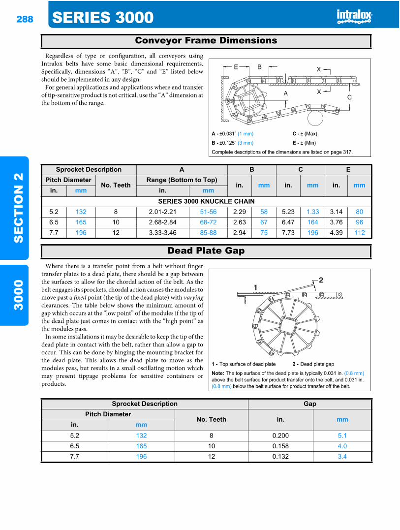
288 SERIES 3000S
EC
TIO
N 2
3000
Regardless of type or configuration, all conveyors usingIntralox belts have some basic dimensional requirements.Specifically, dimensions “A”, “B”, “C” and “E” listed belowshould be implemented in any design.
For general applications and applications where end transferof tip-sensitive product is not critical, use the “A” dimension atthe bottom of the range.
Where there is a transfer point from a belt without fingertransfer plates to a dead plate, there should be a gap betweenthe surfaces to allow for the chordal action of the belt. As thebelt engages its sprockets, chordal action causes the modules tomove past a fixed point (the tip of the dead plate) with varyingclearances. The table below shows the minimum amount ofgap which occurs at the “low point” of the modules if the tip ofthe dead plate just comes in contact with the “high point” asthe modules pass.
In some installations it may be desirable to keep the tip of thedead plate in contact with the belt, rather than allow a gap tooccur. This can be done by hinging the mounting bracket forthe dead plate. This allows the dead plate to move as themodules pass, but results in a small oscillating motion whichmay present tippage problems for sensitive containers orproducts.
Conveyor Frame Dimensions
A - ±0.031” (1 mm) C - ± (Max)
B - ±0.125” (3 mm) E - ± (Min)
Complete descriptions of the dimensions are listed on page 317.
Sprocket Description A B C EPitch Diameter
No. TeethRange (Bottom to Top)
in. mm in. mm in. mmin. mm in. mm
SERIES 3000 KNUCKLE CHAIN5.2 132 8 2.01-2.21 51-56 2.29 58 5.23 1.33 3.14 806.5 165 10 2.68-2.84 68-72 2.63 67 6.47 164 3.76 967.7 196 12 3.33-3.46 85-88 2.94 75 7.73 196 4.39 112
Dead Plate Gap
1 - Top surface of dead plate 2 - Dead plate gap
Note: The top surface of the dead plate is typically 0.031 in. (0.8 mm)above the belt surface for product transfer onto the belt, and 0.031 in. (0.8 mm) below the belt surface for product transfer off the belt.
21
Sprocket Description GapPitch Diameter
No. Teeth in. mmin. mm5.2 132 8 0.200 5.16.5 165 10 0.158 4.07.7 196 12 0.132 3.4
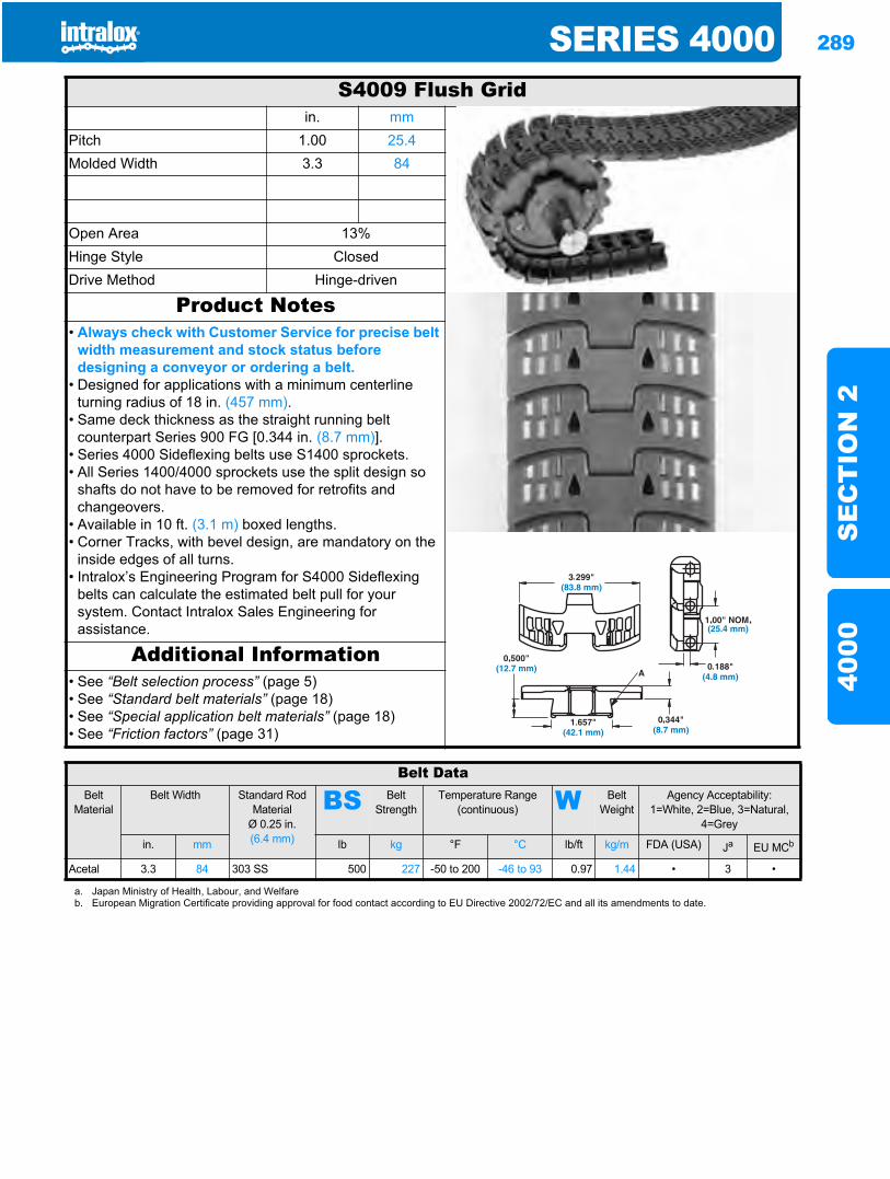
SERIES 4000 289
SE
CT
ION
240
00
Series 40004000
S4009 Flush Gridin. mm
Pitch 1.00 25.4Molded Width 3.3 84
Open Area 13%Hinge Style ClosedDrive Method Hinge-driven
Product Notes• Always check with Customer Service for precise belt
width measurement and stock status before designing a conveyor or ordering a belt.
• Designed for applications with a minimum centerline turning radius of 18 in. (457 mm).
• Same deck thickness as the straight running belt counterpart Series 900 FG [0.344 in. (8.7 mm)].
• Series 4000 Sideflexing belts use S1400 sprockets.• All Series 1400/4000 sprockets use the split design so
shafts do not have to be removed for retrofits and changeovers.
• Available in 10 ft. (3.1 m) boxed lengths.• Corner Tracks, with bevel design, are mandatory on the
inside edges of all turns.• Intralox’s Engineering Program for S4000 Sideflexing
belts can calculate the estimated belt pull for your system. Contact Intralox Sales Engineering for assistance.
Additional Information• See “Belt selection process” (page 5)• See “Standard belt materials” (page 18)• See “Special application belt materials” (page 18)• See “Friction factors” (page 31)
Belt DataBelt
MaterialBelt Width Standard Rod
MaterialØ 0.25 in. (6.4 mm)
BS Belt Strength
Temperature Range (continuous) W Belt
WeightAgency Acceptability:
1=White, 2=Blue, 3=Natural, 4=Grey
in. mm lb kg °F °C lb/ft kg/m FDA (USA) Ja EU MCb
Acetal 3.3 84 303 SS 500 227 -50 to 200 -46 to 93 0.97 1.44 • 3 •
a. Japan Ministry of Health, Labour, and Welfareb. European Migration Certificate providing approval for food contact according to EU Directive 2002/72/EC and all its amendments to date.
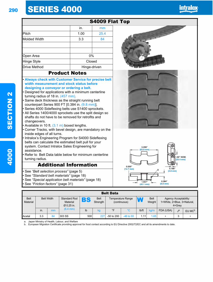
290 SERIES 4000S
EC
TIO
N 2
4000
S4009 Flat Topin. mm
Pitch 1.00 25.4Molded Width 3.3 84
Open Area 0%Hinge Style ClosedDrive Method Hinge-driven
Product Notes• Always check with Customer Service for precise belt
width measurement and stock status before designing a conveyor or ordering a belt.
• Designed for applications with a minimum centerline turning radius of 18 in. (457 mm).
• Same deck thickness as the straight running belt counterpart Series 900 FT [0.384 in. (9.8 mm)].
• Series 4000 Sideflexing belts use S1400 sprockets.• All Series 1400/4000 sprockets use the split design so
shafts do not have to be removed for retrofits and changeovers.
• Available in 10 ft. (3.1 m) boxed lengths.• Corner Tracks, with bevel design, are mandatory on the
inside edges of all turns.• Intralox’s Engineering Program for S4000 Sideflexing
belts can calculate the estimated belt pull for your system. Contact Intralox Sales Engineering for assistance.
• Refer to Belt Data table below for minimum centerline turning radius.
Additional Information• See “Belt selection process” (page 5)• See “Standard belt materials” (page 18)• See “Special application belt materials” (page 18)• See “Friction factors” (page 31)
Belt DataBelt
MaterialBelt Width Standard Rod
MaterialØ 0.25 in. (6.4 mm)
BS Belt Strength
Temperature Range (continuous) W Belt
WeightAgency Acceptability:
1=White, 2=Blue, 3=Natural, 4=Grey
in. mm lb kg °F °C lb/ft kg/m FDA (USA) Ja EU MCb
Acetal 3.3 84 303 SS 500 227 -50 to 200 -46 to 93 1.11 1.65 • 3 •
a. Japan Ministry of Health, Labour, and Welfareb. European Migration Certificate providing approval for food contact according to EU Directive 2002/72/EC and all its amendments to date.
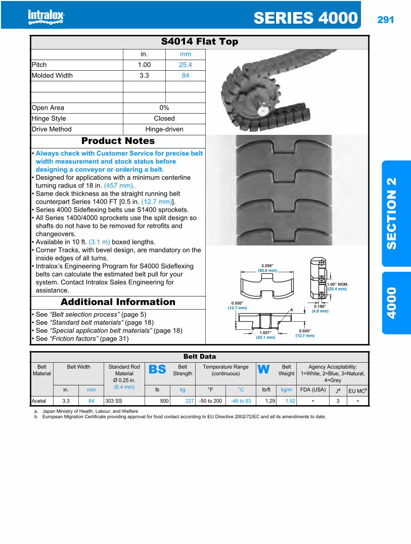
SERIES 4000 291
SE
CT
ION
240
00
S4014 Flat Topin. mm
Pitch 1.00 25.4Molded Width 3.3 84
Open Area 0%Hinge Style ClosedDrive Method Hinge-driven
Product Notes• Always check with Customer Service for precise belt
width measurement and stock status before designing a conveyor or ordering a belt.
• Designed for applications with a minimum centerline turning radius of 18 in. (457 mm).
• Same deck thickness as the straight running belt counterpart Series 1400 FT [0.5 in. (12.7 mm)].
• Series 4000 Sideflexing belts use S1400 sprockets.• All Series 1400/4000 sprockets use the split design so
shafts do not have to be removed for retrofits and changeovers.
• Available in 10 ft. (3.1 m) boxed lengths.• Corner Tracks, with bevel design, are mandatory on the
inside edges of all turns.• Intralox’s Engineering Program for S4000 Sideflexing
belts can calculate the estimated belt pull for your system. Contact Intralox Sales Engineering for assistance.
Additional Information• See “Belt selection process” (page 5)• See “Standard belt materials” (page 18)• See “Special application belt materials” (page 18)• See “Friction factors” (page 31)
Belt DataBelt
MaterialBelt Width Standard Rod
MaterialØ 0.25 in. (6.4 mm)
BS Belt Strength
Temperature Range (continuous) W Belt
WeightAgency Acceptability:
1=White, 2=Blue, 3=Natural, 4=Grey
in. mm lb kg °F °C lb/ft kg/m FDA (USA) Ja EU MCb
Acetal 3.3 84 303 SS 500 227 -50 to 200 -46 to 93 1.29 1.92 • 3 •
a. Japan Ministry of Health, Labour, and Welfareb. European Migration Certificate providing approval for food contact according to EU Directive 2002/72/EC and all its amendments to date.
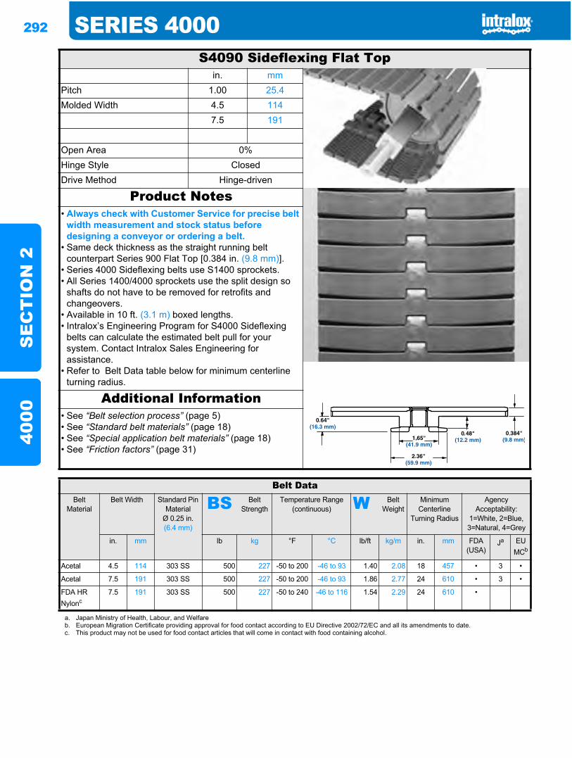
292 SERIES 4000S
EC
TIO
N 2
4000
S4090 Sideflexing Flat Topin. mm
Pitch 1.00 25.4Molded Width 4.5 114
7.5 191
Open Area 0%Hinge Style ClosedDrive Method Hinge-driven
Product Notes• Always check with Customer Service for precise belt
width measurement and stock status before designing a conveyor or ordering a belt.
• Same deck thickness as the straight running belt counterpart Series 900 Flat Top [0.384 in. (9.8 mm)].
• Series 4000 Sideflexing belts use S1400 sprockets.• All Series 1400/4000 sprockets use the split design so
shafts do not have to be removed for retrofits and changeovers.
• Available in 10 ft. (3.1 m) boxed lengths.• Intralox’s Engineering Program for S4000 Sideflexing
belts can calculate the estimated belt pull for your system. Contact Intralox Sales Engineering for assistance.
• Refer to Belt Data table below for minimum centerline turning radius.
Additional Information• See “Belt selection process” (page 5)• See “Standard belt materials” (page 18)• See “Special application belt materials” (page 18)• See “Friction factors” (page 31)
Belt DataBelt
MaterialBelt Width Standard Pin
MaterialØ 0.25 in. (6.4 mm)
BS Belt Strength
Temperature Range (continuous) W Belt
WeightMinimum Centerline
Turning Radius
Agency Acceptability:
1=White, 2=Blue, 3=Natural, 4=Grey
in. mm lb kg °F °C lb/ft kg/m in. mm FDA (USA)
Ja EU MCb
Acetal 4.5 114 303 SS 500 227 -50 to 200 -46 to 93 1.40 2.08 18 457 • 3 •
Acetal 7.5 191 303 SS 500 227 -50 to 200 -46 to 93 1.86 2.77 24 610 • 3 •
FDA HR Nylonc
7.5 191 303 SS 500 227 -50 to 240 -46 to 116 1.54 2.29 24 610 •
a. Japan Ministry of Health, Labour, and Welfareb. European Migration Certificate providing approval for food contact according to EU Directive 2002/72/EC and all its amendments to date.c. This product may not be used for food contact articles that will come in contact with food containing alcohol.
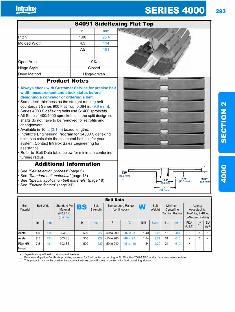
SERIES 4000 293
SE
CT
ION
240
00
S4091 Sideflexing Flat Topin. mm
Pitch 1.00 25.4Molded Width 4.5 114
7.5 191
Open Area 0%Hinge Style ClosedDrive Method Hinge-driven
Product Notes• Always check with Customer Service for precise belt
width measurement and stock status before designing a conveyor or ordering a belt.
• Same deck thickness as the straight running belt counterpart Series 900 Flat Top [0.384 in. (9.8 mm)].
• Series 4000 Sideflexing belts use S1400 sprockets.• All Series 1400/4000 sprockets use the split design so
shafts do not have to be removed for retrofits and changeovers.
• Available in 10 ft. (3.1 m) boxed lengths.• Intralox’s Engineering Program for S4000 Sideflexing
belts can calculate the estimated belt pull for your system. Contact Intralox Sales Engineering for assistance.
• Refer to Belt Data table below for minimum centerline turning radius.
Additional Information• See “Belt selection process” (page 5)• See “Standard belt materials” (page 18)• See “Special application belt materials” (page 18)• See “Friction factors” (page 31)
Belt DataBelt
MaterialBelt Width Standard Pin
MaterialØ 0.25 in. (6.4 mm)
BS Belt Strength
Temperature Range (continuous) W Belt
WeightMinimum Centerline
Turning Radius
Agency Acceptability:
1=White, 2=Blue, 3=Natural, 4=Grey
in. mm lb kg °F °C lb/ft kg/m in. mm FDA(USA)
Ja EU MCb
Acetal 4.5 114 303 SS 500 227 -50 to 200 -46 to 93 1.40 2.08 18 457 • 3 •
Acetal 7.5 191 303 SS 500 227 -50 to 200 -46 to 93 1.84 2.74 24 610 • 3 •
FDA HR Nylonc
7.5 191 303 SS 500 227 -50 to 240 -46 to 116 1.54 2.29 24 610 •
a. Japan Ministry of Health, Labour, and Welfareb. European Migration Certificate providing approval for food contact according to EU Directive 2002/72/EC and all its amendments to date.c. This product may not be used for food contact articles that will come in contact with food containing alcohol.
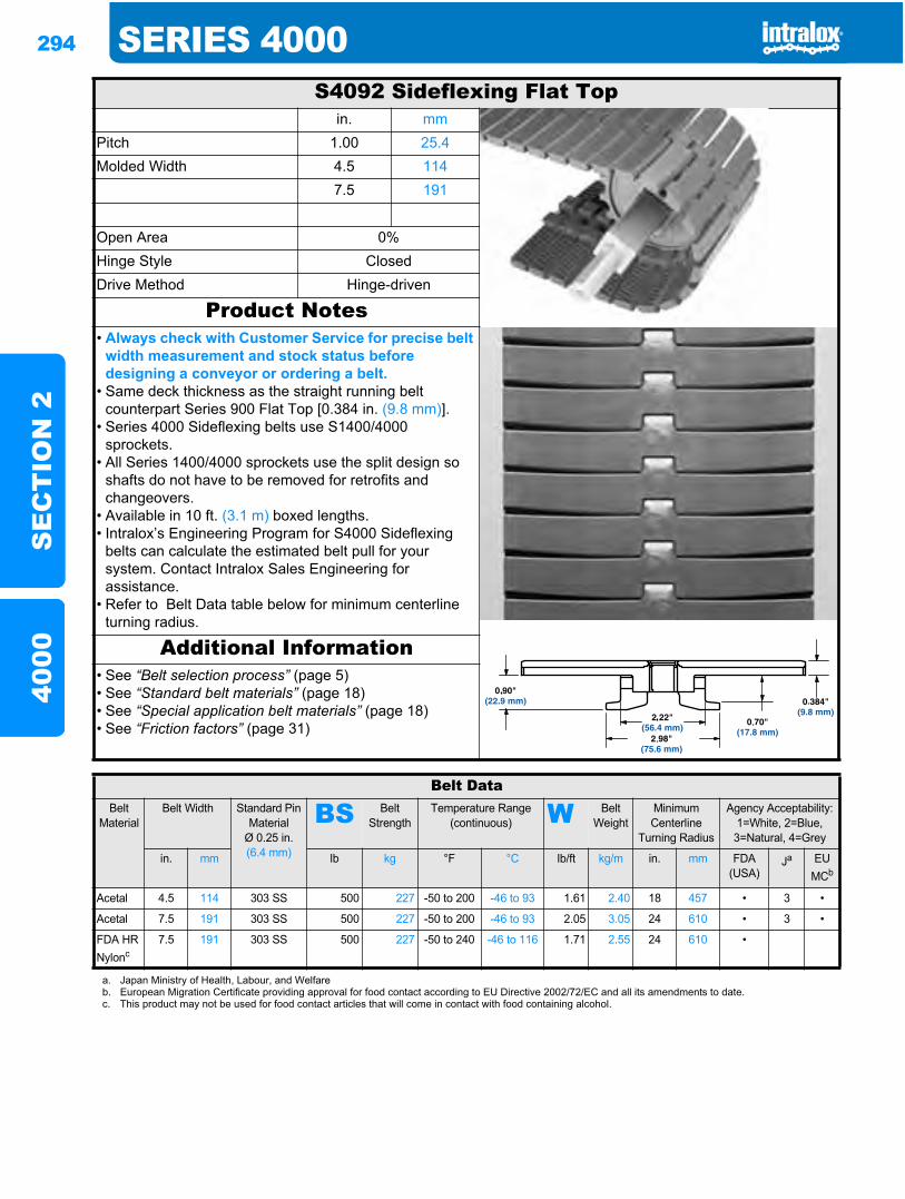
294 SERIES 4000S
EC
TIO
N 2
4000
S4092 Sideflexing Flat Topin. mm
Pitch 1.00 25.4Molded Width 4.5 114
7.5 191
Open Area 0%Hinge Style ClosedDrive Method Hinge-driven
Product Notes• Always check with Customer Service for precise belt
width measurement and stock status before designing a conveyor or ordering a belt.
• Same deck thickness as the straight running belt counterpart Series 900 Flat Top [0.384 in. (9.8 mm)].
• Series 4000 Sideflexing belts use S1400/4000 sprockets.
• All Series 1400/4000 sprockets use the split design so shafts do not have to be removed for retrofits and changeovers.
• Available in 10 ft. (3.1 m) boxed lengths.• Intralox’s Engineering Program for S4000 Sideflexing
belts can calculate the estimated belt pull for your system. Contact Intralox Sales Engineering for assistance.
• Refer to Belt Data table below for minimum centerline turning radius.
Additional Information• See “Belt selection process” (page 5)• See “Standard belt materials” (page 18)• See “Special application belt materials” (page 18)• See “Friction factors” (page 31)
Belt DataBelt
MaterialBelt Width Standard Pin
MaterialØ 0.25 in. (6.4 mm)
BS Belt Strength
Temperature Range (continuous) W Belt
WeightMinimum Centerline
Turning Radius
Agency Acceptability:1=White, 2=Blue, 3=Natural, 4=Grey
in. mm lb kg °F °C lb/ft kg/m in. mm FDA(USA)
Ja EU MCb
Acetal 4.5 114 303 SS 500 227 -50 to 200 -46 to 93 1.61 2.40 18 457 • 3 •
Acetal 7.5 191 303 SS 500 227 -50 to 200 -46 to 93 2.05 3.05 24 610 • 3 •
FDA HR Nylonc
7.5 191 303 SS 500 227 -50 to 240 -46 to 116 1.71 2.55 24 610 •
a. Japan Ministry of Health, Labour, and Welfareb. European Migration Certificate providing approval for food contact according to EU Directive 2002/72/EC and all its amendments to date.c. This product may not be used for food contact articles that will come in contact with food containing alcohol.
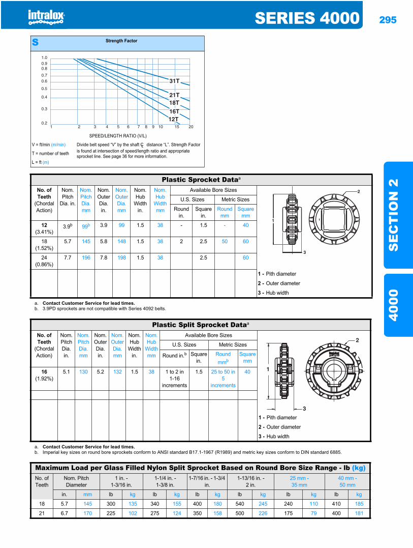
SERIES 4000 295
SE
CT
ION
240
00
S Strength Factor
SPEED/LENGTH RATIO (V/L)
V = ft/min (m/min) Divide belt speed “V” by the shaft CL distance “L”. Strength Factor is found at intersection of speed/length ratio and appropriate sprocket line. See page 36 for more information.T = number of teeth
L = ft (m)
1.00.90.8
0.70.6
0.5
0.4
0.3
0.21 2 3 4 5 6 7 8 9 10 15 20
Plastic Sprocket Dataa
No. of Teeth
(Chordal Action)
Nom. Pitch
Dia. in.
Nom. Pitch Dia. mm
Nom. Outer Dia.in.
Nom. Outer Dia.mm
Nom. Hub
Width in.
Nom. Hub
Width mm
Available Bore Sizes
U.S. Sizes Metric Sizes
Round in.
Square in.
Round mm
Square mm
12(3.41%)
3.9b 99b 3.9 99 1.5 38 - 1.5 - 40
18(1.52%)
5.7 145 5.8 148 1.5 38 2 2.5 50 60
24(0.86%)
7.7 196 7.8 198 1.5 38 2.5 60
1 - Pith diameter
2 - Outer diameter
3 - Hub width
a. Contact Customer Service for lead times.b. 3.9PD sprockets are not compatible with Series 4092 belts.
Plastic Split Sprocket Dataa
No. of Teeth
(Chordal Action)
Nom. Pitch Dia. in.
Nom. Pitch Dia. mm
Nom. OuterDia. in.
Nom. OuterDia. mm
Nom. Hub
Width in.
Nom. Hub
Width mm
Available Bore Sizes
U.S. Sizes Metric Sizes
Round in.b Square in.
Round mmb
Square mm
16(1.92%)
5.1 130 5.2 132 1.5 38 1 to 2 in1-16
increments
1.5 25 to 50 in5
increments
40
1 - Pith diameter
2 - Outer diameter
3 - Hub width
a. Contact Customer Service for lead times.b. Imperial key sizes on round bore sprockets conform to ANSI standard B17.1-1967 (R1989) and metric key sizes conform to DIN standard 6885.
Maximum Load per Glass Filled Nylon Split Sprocket Based on Round Bore Size Range - lb (kg)No. ofTeeth
Nom. Pitch Diameter
1 in. -1-3/16 in.
1-1/4 in. -1-3/8 in.
1-7/16 in. - 1-3/4 in.
1-13/16 in. -2 in.
25 mm -35 mm
40 mm -50 mm
in. mm lb kg lb kg lb kg lb kg lb kg lb kg
18 5.7 145 300 135 340 155 400 180 540 245 240 110 410 185
21 6.7 170 225 102 275 124 350 158 500 226 175 79 400 181
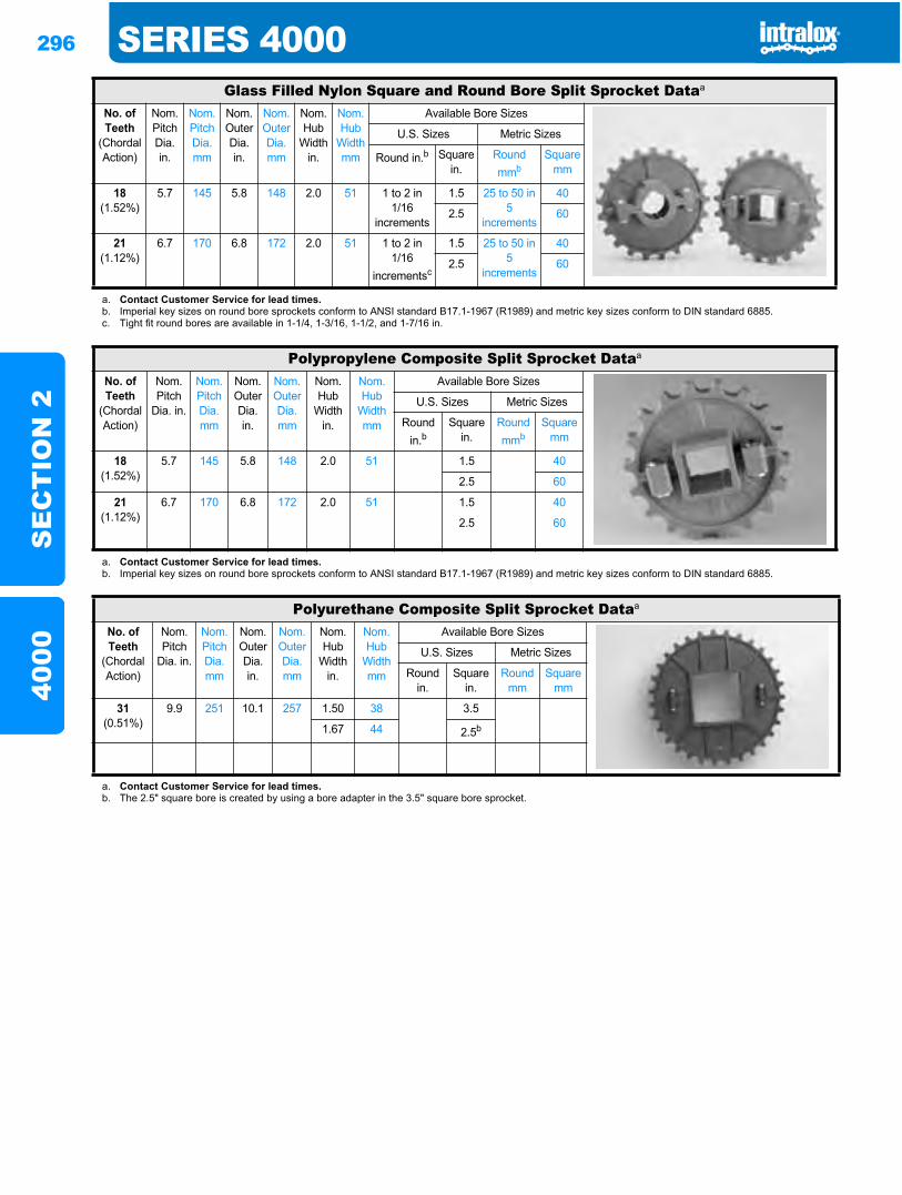
296 SERIES 4000S
EC
TIO
N 2
4000
Glass Filled Nylon Square and Round Bore Split Sprocket Dataa
No. of Teeth
(Chordal Action)
Nom. Pitch Dia.in.
Nom. Pitch Dia.mm
Nom. Outer Dia.in.
Nom. Outer Dia.mm
Nom. Hub
Width in.
Nom. Hub
Width mm
Available Bore Sizes
U.S. Sizes Metric Sizes
Round in.b Square in.
Round mmb
Square mm
18(1.52%)
5.7 145 5.8 148 2.0 51 1 to 2 in1/16
increments
1.5 25 to 50 in 5
increments
40
2.5 60
21(1.12%)
6.7 170 6.8 172 2.0 51 1 to 2 in1/16
incrementsc
1.5 25 to 50 in 5
increments
40
2.5 60
a. Contact Customer Service for lead times.b. Imperial key sizes on round bore sprockets conform to ANSI standard B17.1-1967 (R1989) and metric key sizes conform to DIN standard 6885.c. Tight fit round bores are available in 1-1/4, 1-3/16, 1-1/2, and 1-7/16 in.
Polypropylene Composite Split Sprocket Dataa
No. of Teeth
(Chordal Action)
Nom. Pitch
Dia. in.
Nom. Pitch Dia. mm
Nom. Outer Dia.in.
Nom. Outer Dia.mm
Nom. Hub
Width in.
Nom. Hub
Width mm
Available Bore Sizes
U.S. Sizes Metric Sizes
Round in.b
Square in.
Round mmb
Square mm
18(1.52%)
5.7 145 5.8 148 2.0 51 1.5 40
2.5 60
21(1.12%)
6.7 170 6.8 172 2.0 51 1.5 40
2.5 60
a. Contact Customer Service for lead times.b. Imperial key sizes on round bore sprockets conform to ANSI standard B17.1-1967 (R1989) and metric key sizes conform to DIN standard 6885.
Polyurethane Composite Split Sprocket Dataa
No. of Teeth
(Chordal Action)
Nom. Pitch
Dia. in.
Nom. Pitch Dia. mm
Nom. Outer Dia.in.
Nom. Outer Dia.mm
Nom. Hub
Width in.
Nom. Hub
Width mm
Available Bore Sizes
U.S. Sizes Metric Sizes
Round in.
Square in.
Round mm
Square mm
31(0.51%)
9.9 251 10.1 257 1.50 38 3.5
1.67 44 2.5b
a. Contact Customer Service for lead times.b. The 2.5" square bore is created by using a bore adapter in the 3.5" square bore sprocket.
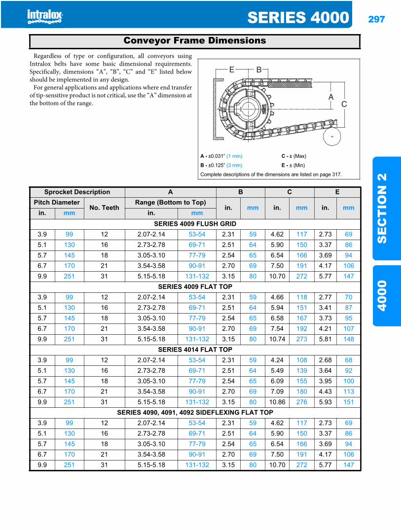
SERIES 4000 297
SE
CT
ION
240
00
Regardless of type or configuration, all conveyors usingIntralox belts have some basic dimensional requirements.Specifically, dimensions “A”, “B”, “C” and “E” listed belowshould be implemented in any design.
For general applications and applications where end transferof tip-sensitive product is not critical, use the “A” dimension atthe bottom of the range.
Conveyor Frame Dimensions
A - ±0.031” (1 mm) C - ± (Max)
B - ±0.125” (3 mm) E - ± (Min)
Complete descriptions of the dimensions are listed on page 317.
Sprocket Description A B C EPitch Diameter
No. TeethRange (Bottom to Top)
in. mm in. mm in. mmin. mm in. mm
SERIES 4009 FLUSH GRID3.9 99 12 2.07-2.14 53-54 2.31 59 4.62 117 2.73 695.1 130 16 2.73-2.78 69-71 2.51 64 5.90 150 3.37 865.7 145 18 3.05-3.10 77-79 2.54 65 6.54 166 3.69 946.7 170 21 3.54-3.58 90-91 2.70 69 7.50 191 4.17 1069.9 251 31 5.15-5.18 131-132 3.15 80 10.70 272 5.77 147
SERIES 4009 FLAT TOP3.9 99 12 2.07-2.14 53-54 2.31 59 4.66 118 2.77 705.1 130 16 2.73-2.78 69-71 2.51 64 5.94 151 3.41 875.7 145 18 3.05-3.10 77-79 2.54 65 6.58 167 3.73 956.7 170 21 3.54-3.58 90-91 2.70 69 7.54 192 4.21 1079.9 251 31 5.15-5.18 131-132 3.15 80 10.74 273 5.81 148
SERIES 4014 FLAT TOP3.9 99 12 2.07-2.14 53-54 2.31 59 4.24 108 2.68 685.1 130 16 2.73-2.78 69-71 2.51 64 5.49 139 3.64 925.7 145 18 3.05-3.10 77-79 2.54 65 6.09 155 3.95 1006.7 170 21 3.54-3.58 90-91 2.70 69 7.09 180 4.43 1139.9 251 31 5.15-5.18 131-132 3.15 80 10.86 276 5.93 151
SERIES 4090, 4091, 4092 SIDEFLEXING FLAT TOP3.9 99 12 2.07-2.14 53-54 2.31 59 4.62 117 2.73 695.1 130 16 2.73-2.78 69-71 2.51 64 5.90 150 3.37 865.7 145 18 3.05-3.10 77-79 2.54 65 6.54 166 3.69 946.7 170 21 3.54-3.58 90-91 2.70 69 7.50 191 4.17 1069.9 251 31 5.15-5.18 131-132 3.15 80 10.70 272 5.77 147
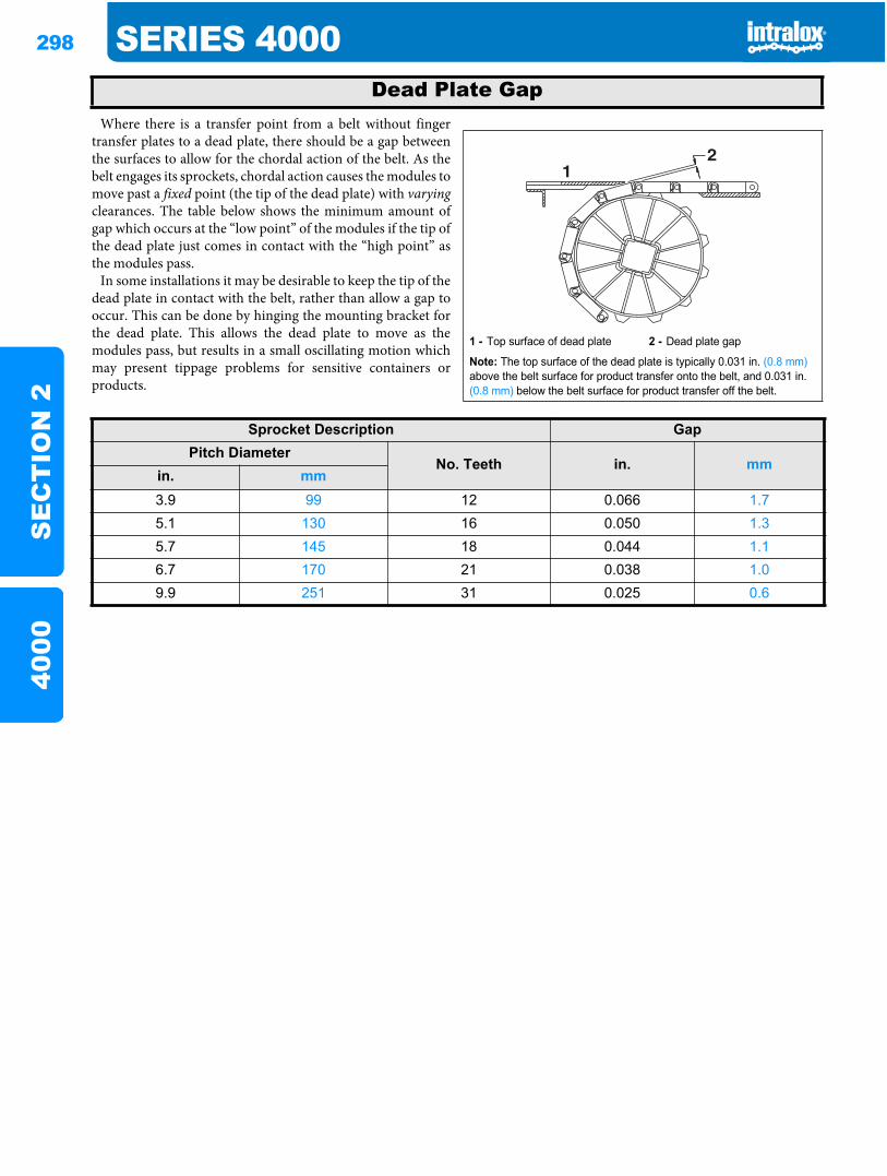
298 SERIES 4000S
EC
TIO
N 2
4000
Where there is a transfer point from a belt without fingertransfer plates to a dead plate, there should be a gap betweenthe surfaces to allow for the chordal action of the belt. As thebelt engages its sprockets, chordal action causes the modules tomove past a fixed point (the tip of the dead plate) with varyingclearances. The table below shows the minimum amount ofgap which occurs at the “low point” of the modules if the tip ofthe dead plate just comes in contact with the “high point” asthe modules pass.
In some installations it may be desirable to keep the tip of thedead plate in contact with the belt, rather than allow a gap tooccur. This can be done by hinging the mounting bracket forthe dead plate. This allows the dead plate to move as themodules pass, but results in a small oscillating motion whichmay present tippage problems for sensitive containers orproducts.
Dead Plate Gap
1 - Top surface of dead plate 2 - Dead plate gap
Note: The top surface of the dead plate is typically 0.031 in. (0.8 mm)above the belt surface for product transfer onto the belt, and 0.031 in. (0.8 mm) below the belt surface for product transfer off the belt.
21
Sprocket Description GapPitch Diameter
No. Teeth in. mmin. mm3.9 99 12 0.066 1.75.1 130 16 0.050 1.35.7 145 18 0.044 1.16.7 170 21 0.038 1.09.9 251 31 0.025 0.6
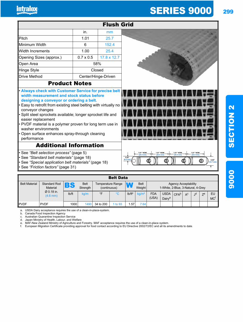
SERIES 9000 299
SE
CT
ION
290
00
Series 90009000
Flush Gridin. mm
Pitch 1.01 25.7Minimum Width 6 152.4Width Increments 1.00 25.4Opening Sizes (approx.) 0.7 x 0.5 17.8 x 12.7Open Area 58%Hinge Style ClosedDrive Method Center/Hinge-Driven
Product Notes• Always check with Customer Service for precise belt
width measurement and stock status before designing a conveyor or ordering a belt.
• Easy to retrofit from existing steel belting with virtually no conveyor changes
• Split steel sprockets available; longer sprocket life and easier replacement
• PVDF material is a polymer proven for long term use in washer environments
• Open surface enhances spray-through cleaning performance
Additional Information• See “Belt selection process” (page 5)• See “Standard belt materials” (page 18)• See “Special application belt materials” (page 18)• See “Friction factors” (page 31)
0.50"(12.7 mm)
0.25"(6.4 mm)
1.01" NOM.(25.4 mm)
1.01" NOM.(25.4 mm)
1.01" NOM.(25.4 mm)
1.01" NOM.(25.4 mm)
Belt DataBelt Material Standard Rod
MaterialØ 0.18 in. (4.6 mm)
BS Belt Strength
Temperature Range (continuous) W Belt
WeightAgency Acceptability
1-White, 2-Blue, 3-Natural, 4-Grey
lb/ft kg/m °F °C lb/ft² kg/m² FDA (USA)
USDADairya
CFAb Ac Jd Ze EU MCf
PVDF PVDF 1000 1490 34 to 200 1 to 93 1.57 7.64
a. USDA Dairy acceptance requires the use of a clean-in-place-system.b. Canada Food Inspection Agencyc. Australian Quarantine Inspection Serviced. Japan Ministry of Health, Labour, and Welfaree. MAF-New Zealand Ministry of Agriculture and Forestry. MAF acceptance requires the use of a clean-in-place system.f. European Migration Certificate providing approval for food contact according to EU Directive 2002/72/EC and all its amendments to date.
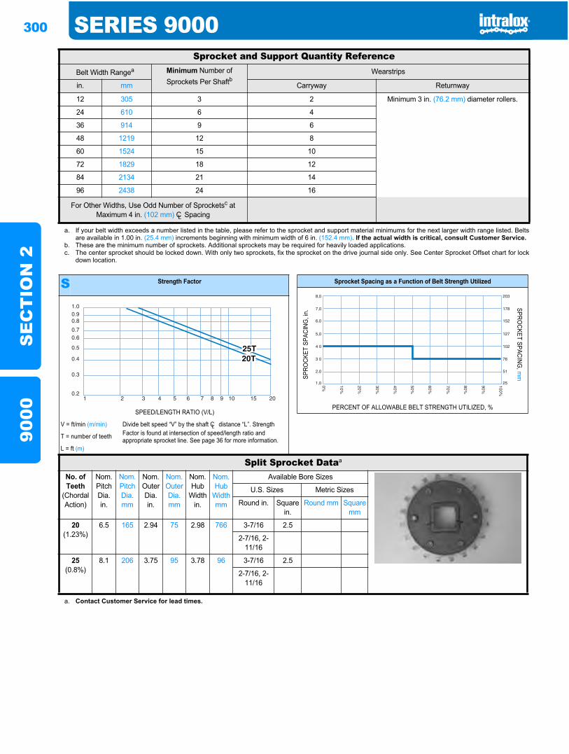
300 SERIES 9000S
EC
TIO
N 2
9000
Sprocket and Support Quantity ReferenceBelt Width Rangea Minimum Number of
Sprockets Per ShaftbWearstrips
in. mm Carryway Returnway
12 305 3 2 Minimum 3 in. (76.2 mm) diameter rollers.
24 610 6 4
36 914 9 6
48 1219 12 8
60 1524 15 10
72 1829 18 12
84 2134 21 14
96 2438 24 16
For Other Widths, Use Odd Number of Sprocketsc at Maximum 4 in. (102 mm) CL Spacing
a. If your belt width exceeds a number listed in the table, please refer to the sprocket and support material minimums for the next larger width range listed. Beltsare available in 1.00 in. (25.4 mm) increments beginning with minimum width of 6 in. (152.4 mm). If the actual width is critical, consult Customer Service.
b. These are the minimum number of sprockets. Additional sprockets may be required for heavily loaded applications.c. The center sprocket should be locked down. With only two sprockets, fix the sprocket on the drive journal side only. See Center Sprocket Offset chart for lock
down location.
S Strength Factor
SPEED/LENGTH RATIO (V/L)
V = ft/min (m/min) Divide belt speed “V” by the shaft CL distance “L”. Strength Factor is found at intersection of speed/length ratio and appropriate sprocket line. See page 36 for more information.T = number of teeth
L = ft (m)
1.00.90.8
0.70.6
0.5
0.4
0.3
0.21 2 3 4 5 6 7 8 9 10 15 20
Sprocket Spacing as a Function of Belt Strength Utilized
SPRO
CKET
SPA
CING
, in.
SPROCKET SPACING
, mm
PERCENT OF ALLOWABLE BELT STRENGTH UTILIZED, %
Split Sprocket Dataa
No. of Teeth
(Chordal Action)
Nom. Pitch Dia. in.
Nom. Pitch Dia.mm
Nom. Outer Dia.in.
Nom. Outer Dia.mm
Nom. Hub
Width in.
Nom. Hub
Width mm
Available Bore Sizes
U.S. Sizes Metric Sizes
Round in. Square in.
Round mm Square mm
20(1.23%)
6.5 165 2.94 75 2.98 766 3-7/16 2.5
2-7/16, 2-11/16
25(0.8%)
8.1 206 3.75 95 3.78 96 3-7/16 2.5
2-7/16, 2-11/16
a. Contact Customer Service for lead times.
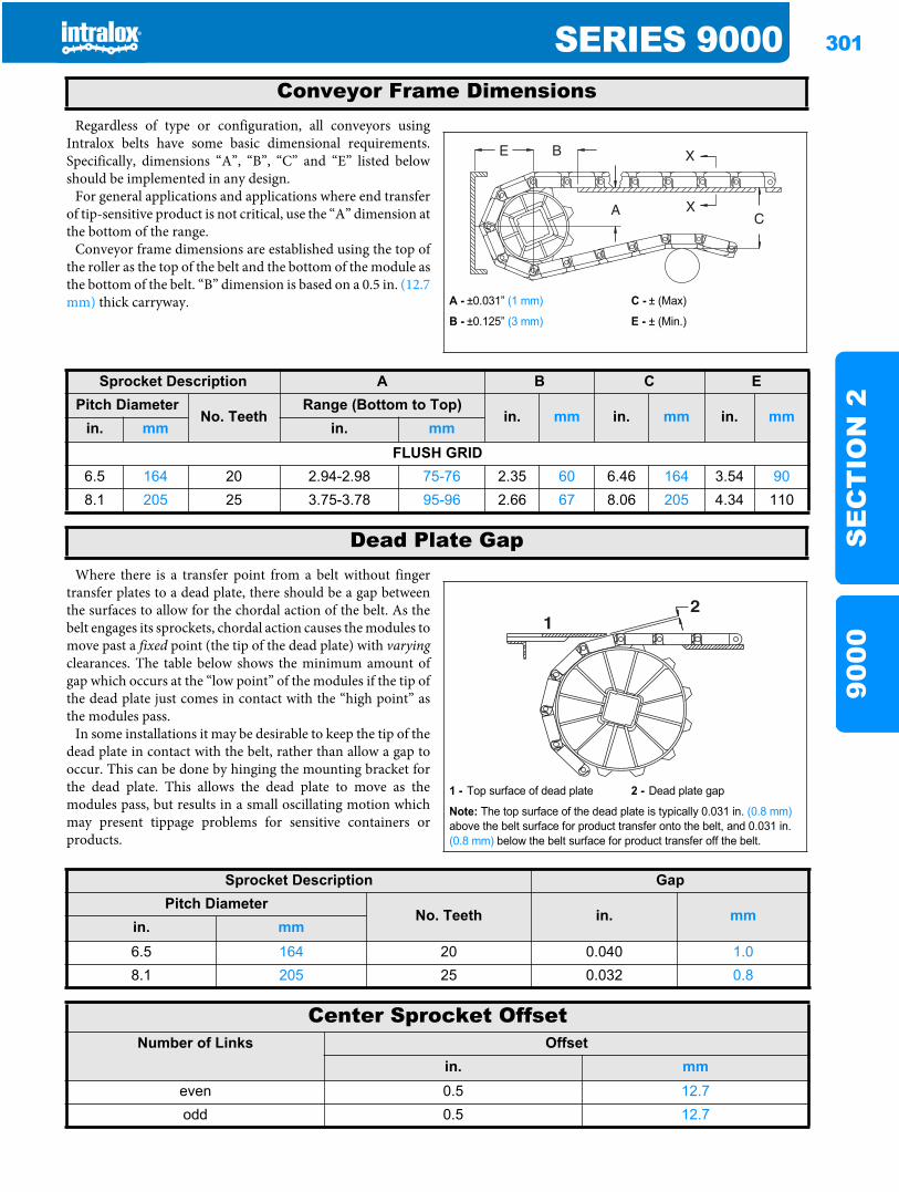
SERIES 9000 301
SE
CT
ION
290
00
Regardless of type or configuration, all conveyors usingIntralox belts have some basic dimensional requirements.Specifically, dimensions “A”, “B”, “C” and “E” listed belowshould be implemented in any design.
For general applications and applications where end transferof tip-sensitive product is not critical, use the “A” dimension atthe bottom of the range.
Conveyor frame dimensions are established using the top ofthe roller as the top of the belt and the bottom of the module asthe bottom of the belt. “B” dimension is based on a 0.5 in. (12.7mm) thick carryway.
Where there is a transfer point from a belt without fingertransfer plates to a dead plate, there should be a gap betweenthe surfaces to allow for the chordal action of the belt. As thebelt engages its sprockets, chordal action causes the modules tomove past a fixed point (the tip of the dead plate) with varyingclearances. The table below shows the minimum amount ofgap which occurs at the “low point” of the modules if the tip ofthe dead plate just comes in contact with the “high point” asthe modules pass.
In some installations it may be desirable to keep the tip of thedead plate in contact with the belt, rather than allow a gap tooccur. This can be done by hinging the mounting bracket forthe dead plate. This allows the dead plate to move as themodules pass, but results in a small oscillating motion whichmay present tippage problems for sensitive containers orproducts.
Conveyor Frame Dimensions
A - ±0.031” (1 mm) C - ± (Max)
B - ±0.125” (3 mm) E - ± (Min.)
Sprocket Description A B C EPitch Diameter
No. TeethRange (Bottom to Top)
in. mm in. mm in. mmin. mm in. mm
FLUSH GRID6.5 164 20 2.94-2.98 75-76 2.35 60 6.46 164 3.54 908.1 205 25 3.75-3.78 95-96 2.66 67 8.06 205 4.34 110
Dead Plate Gap
1 - Top surface of dead plate 2 - Dead plate gap
Note: The top surface of the dead plate is typically 0.031 in. (0.8 mm)above the belt surface for product transfer onto the belt, and 0.031 in. (0.8 mm) below the belt surface for product transfer off the belt.
21
Sprocket Description GapPitch Diameter
No. Teeth in. mmin. mm6.5 164 20 0.040 1.08.1 205 25 0.032 0.8
Center Sprocket OffsetNumber of Links Offset
in. mmeven 0.5 12.7odd 0.5 12.7

302 SERIES 9000S
EC
TIO
N 2
9000
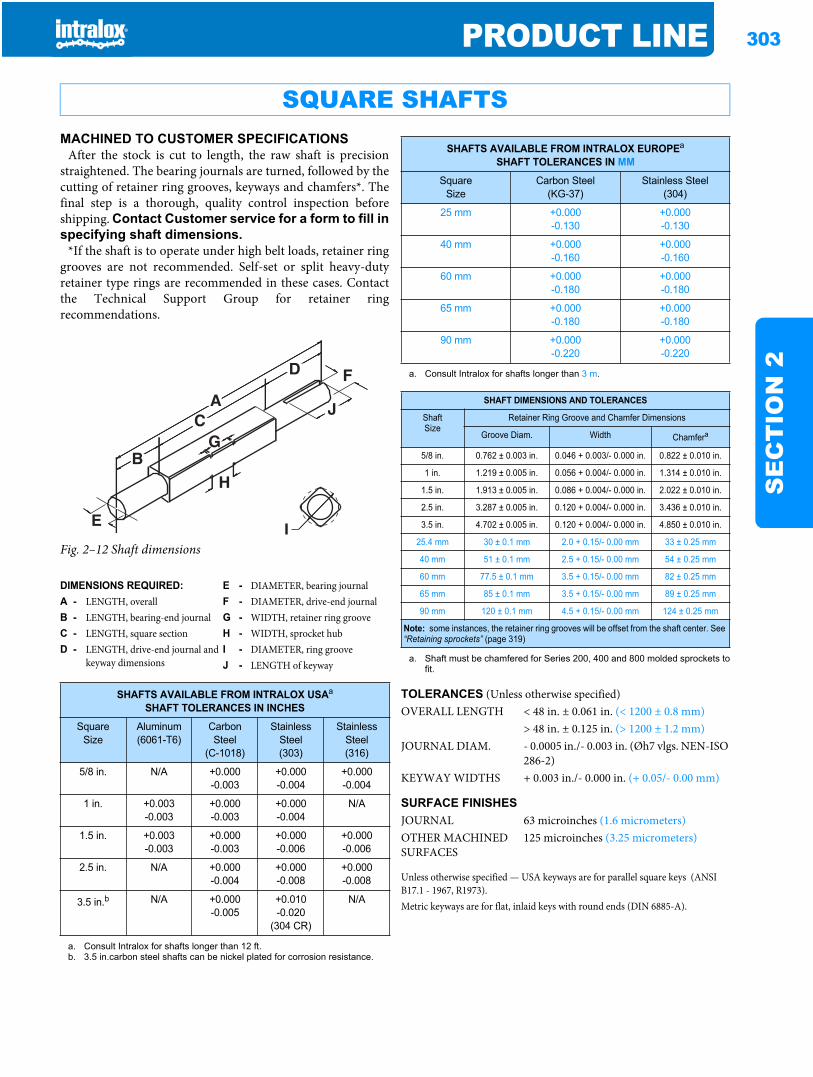
PRODUCT LINE 303
SE
CT
ION
2
Product line
MACHINED TO CUSTOMER SPECIFICATIONSAfter the stock is cut to length, the raw shaft is precision
straightened. The bearing journals are turned, followed by thecutting of retainer ring grooves, keyways and chamfers*. Thefinal step is a thorough, quality control inspection beforeshipping. Contact Customer service for a form to fill inspecifying shaft dimensions.
*If the shaft is to operate under high belt loads, retainer ringgrooves are not recommended. Self-set or split heavy-dutyretainer type rings are recommended in these cases. Contactthe Technical Support Group for retainer ringrecommendations.
Fig. 2–12 Shaft dimensions
SQUARE SHAFTS
DIMENSIONS REQUIRED: E - DIAMETER, bearing journalA - LENGTH, overall F - DIAMETER, drive-end journalB - LENGTH, bearing-end journal G - WIDTH, retainer ring grooveC - LENGTH, square section H - WIDTH, sprocket hubD - LENGTH, drive-end journal and
keyway dimensionsI - DIAMETER, ring grooveJ - LENGTH of keyway
SHAFTS AVAILABLE FROM INTRALOX USAa
SHAFT TOLERANCES IN INCHES
a. Consult Intralox for shafts longer than 12 ft.
SquareSize
Aluminum(6061-T6)
CarbonSteel
(C-1018)
StainlessSteel(303)
StainlessSteel(316)
5/8 in. N/A +0.000-0.003
+0.000-0.004
+0.000-0.004
1 in. +0.003-0.003
+0.000-0.003
+0.000-0.004
N/A
1.5 in. +0.003-0.003
+0.000-0.003
+0.000-0.006
+0.000-0.006
2.5 in. N/A +0.000-0.004
+0.000-0.008
+0.000-0.008
3.5 in.b
b. 3.5 in.carbon steel shafts can be nickel plated for corrosion resistance.
N/A +0.000-0.005
+0.010-0.020
(304 CR)
N/A
SHAFTS AVAILABLE FROM INTRALOX EUROPEa
SHAFT TOLERANCES IN MM
a. Consult Intralox for shafts longer than 3 m.
SquareSize
Carbon Steel(KG-37)
Stainless Steel(304)
25 mm +0.000-0.130
+0.000-0.130
40 mm +0.000-0.160
+0.000-0.160
60 mm +0.000-0.180
+0.000-0.180
65 mm +0.000-0.180
+0.000-0.180
90 mm +0.000-0.220
+0.000-0.220
SHAFT DIMENSIONS AND TOLERANCES
ShaftSize
Retainer Ring Groove and Chamfer Dimensions
Groove Diam. Width Chamfera
a. Shaft must be chamfered for Series 200, 400 and 800 molded sprockets tofit.
5/8 in. 0.762 ± 0.003 in. 0.046 + 0.003/- 0.000 in. 0.822 ± 0.010 in.
1 in. 1.219 ± 0.005 in. 0.056 + 0.004/- 0.000 in. 1.314 ± 0.010 in.
1.5 in. 1.913 ± 0.005 in. 0.086 + 0.004/- 0.000 in. 2.022 ± 0.010 in.
2.5 in. 3.287 ± 0.005 in. 0.120 + 0.004/- 0.000 in. 3.436 ± 0.010 in.
3.5 in. 4.702 ± 0.005 in. 0.120 + 0.004/- 0.000 in. 4.850 ± 0.010 in.
25.4 mm 30 ± 0.1 mm 2.0 + 0.15/- 0.00 mm 33 ± 0.25 mm
40 mm 51 ± 0.1 mm 2.5 + 0.15/- 0.00 mm 54 ± 0.25 mm
60 mm 77.5 ± 0.1 mm 3.5 + 0.15/- 0.00 mm 82 ± 0.25 mm
65 mm 85 ± 0.1 mm 3.5 + 0.15/- 0.00 mm 89 ± 0.25 mm
90 mm 120 ± 0.1 mm 4.5 + 0.15/- 0.00 mm 124 ± 0.25 mm
Note: some instances, the retainer ring grooves will be offset from the shaft center. See “Retaining sprockets” (page 319)
TOLERANCES (Unless otherwise specified)OVERALL LENGTH < 48 in. ± 0.061 in. (< 1200 ± 0.8 mm)
> 48 in. ± 0.125 in. (> 1200 ± 1.2 mm)JOURNAL DIAM. - 0.0005 in./- 0.003 in. (Øh7 vlgs. NEN-ISO
286-2)KEYWAY WIDTHS + 0.003 in./- 0.000 in. (+ 0.05/- 0.00 mm)
SURFACE FINISHESJOURNAL 63 microinches (1.6 micrometers)OTHER MACHINED SURFACES
125 microinches (3.25 micrometers)
Unless otherwise specified — USA keyways are for parallel square keys (ANSI B17.1 - 1967, R1973).Metric keyways are for flat, inlaid keys with round ends (DIN 6885-A).
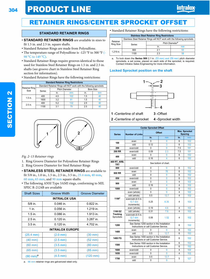
304 PRODUCT LINES
EC
TIO
N 2
• STANDARD RETAINER RINGS are available in sizes to fit 1.5 in. and 2.5 in. square shafts.
• Standard Retainer Rings are made from Polysulfone.• The temperature range of Polysulfone is -125 °F to 300 °F (-
98 °C to 149 °C).• Standard Retainer Rings require grooves identical to those
used for Stainless Steel Retainer Rings on 1.5 in. and 2.5 in. shafts (see groove chart in Stainless Steel Retainer Ring section for information).
• Standard Retainer Rings have the following restrictions:
• STAINLESS STEEL RETAINER RINGS are available to fit 5/8 in., 1.0 in., 1.5 in., 2.5 in., 3.5 in., 25.4 mm, 40 mm, 60 mm, 65 mm, and 90 mm square shafts.
• The following ANSI Type 3AMI rings, conforming to MIL SPEC R-2124B are available
• Standard Retainer Rings have the following restrictions:
Locked Sprocket position on the shaft
RETAINER RINGS/CENTER SPROCKET OFFSETSTANDARD RETAINER RINGS
Standard Retainer Ring Restrictions
Retainer Ring Size
Standard Retainer Rings will NOT work with the following sprockets
SeriesPitch Diameter Bore Size
in. mm in. mm
1.5 in.400 4.0 102 1.5 40
1600 3.2 81 1.5 40
2.5 in.400 5.2 132 2.5 401100 3.1 79 2.5 40
Fig. 2–13 Retainer rings1. Ring Groove Diameter for Polysufone Retainer Rings2. Ring Groove Diameter for Steel Retainer Rings
Shaft Sizes Groove Width Groove Diameter
INTRALOX USA5/8 in. 0.046 in. 0.822 in.
1 in. 0.056 in. 1.219 in.
1.5 in. 0.086 in. 1.913 in.
2.5 in. 0.120 in. 3.287 in.
3.5 in. 0.120 in. 4.702 in.
INTRALOX EUROPE(25.4 mm) (2.0 mm) (30 mm)
(40 mm) (2.5 mm) (52 mm)
(60 mm) (3.5 mm) (80 mm)
(65 mm) (3.5 mm) (85 mm)
(90 mm)a
a. 90 mm retainer rings are galvanized steel only.
(4.5 mm) (120 mm)
Stainless Steel Retainer Ring Restrictions
Retainer Ring Size
Stainless Steel Retainer Rings will NOT work with the following sprockets
Series Pitch Diametera
a. To lock down the Series 900 2.1 in. (53 mm) and (58 mm) pitch diametersprockets, a set screw, placed on each side of the sprocket, is required.Contact Intralox Sales Engineering for more information.
in. mm
1.219 in.900 2.1 531100 2.3 58
1 -Centerline of shaft 3 -Offset2 -Centerline of sprocket 4 -Sprocket width
Center Sprocket Offset
Series Number of LinksOffset Max. Sprocket
Spacingin. mm in. mm
100even 0 0 6 152odd 0.12 3 6 152
200 even/odd 0 0 7.5 191200 RR even/odd 0.09 2.3 7.5 191
400even 0 0 6 152odd 0.16 4 6 152
400 RT, ARB, TRT See bottom of chart.
800 even/odd 0 0 6 152
800 RReven 3 76 6 152odd 0 0 6 152
850 even/odd 0 0 6 152
900even 0 0 4 102odd 0.16 4 4 102
1000 even/odd 0 0 6 152
1100a
even (whole) 0 0 4 102odd (whole) 0.5 12.7 4 102
even/odd (0.5 in. 12.7 mm
increments)0.25 6.35 4 102
1100 EZ TrackingSprockets
even (whole) 0.19 4.8 4 102odd (whole) 0.31 7.9 4 102
even/odd (0.5 in. 12.7 mm
increments)0.06 1.52 4 102
1200 See Series 1200 section in the Installation Instructions or call Customer Service. 6 152
1400even 0 0 6 152odd 0.5 12.7 6 152
1400 FG See Series 1400 section in the Installation Instructions or call Customer Service. 6 152
1500 See Series 1500 section in the Installation Instructions or call Customer Service.
6 1526 152
1600 even/odd 0 0 4 1021650 even/odd 0 0 4 102
1700even 0.5 12.7
5 127odd 0 0
PRODUCT LINE 305
SE
CT
ION
2
•SELF-SET RETAINER RINGS are available to fit 1.0 in., 1.5 in., 2.5 in., 3.5 in., 40 mm, 60 mm, and 65 mm shafts.•Retainer Rings are made from non corrosive 316 stainless steel.•There is no need for machined grooves on the shaft and the shaft does not need to be
removed to install these retainer rings.• Self-Set Retainer Rings are USDA-FSIS accepted.• Self-Set Retainer Rings snap into place on the square shaft
and are fixed in position with a unique set screw that cannot fall out of the retainer ring during operation.
• The shaft must have chamfered edges for the retainer ring to work properly.
• Self-Set Retainer Rings are not recommended in applications where high lateral forces are to be expected.
• Self-Set Retainer Rings have the following restrictions:
• HEAVY DUTY RETAINER RINGS are available to fit 0.75 in., 1.0 in., 20 mm, and 25.4 mm round shafts.
• Heavy Duty Retainer Rings are made of stainless steel.• Heavy Duty Retainer Rings are for use with the Series 1100
1.6 in. (41 mm) and 2.3 in. (58 mm) pitch diameter sprockets.
•These retainer rings do not require a groove for placement, they stay in place using friction (It is very important that grooves are not used on round shafting, as this will cause fatigue and shaft failure).
• SPLIT COLLAR RETAINER RINGS are available to fit 1.5 in., 2.5 in., 40 mm and 60 mm square shafts.
• The retainer rings are made from 304 Stainless Steel.•For use in applications with high lateral loads on the sprockets.•These retainer rings do not require the shaft to be chamfered and the shaft does not have to be removed, providing ease of installation.
• Torque specifications for the retainer rings are as follows:1.5 in. and 40 mm: 90 in-lbs (10.2 N-m)2.5 in. and 60 mm: 190 in-lbs (21.5 N-m)
• Split Collar Retainer Rings have the following restrictions:
1800 even/odd 0 0 6 152
1900 See Series 1900 section in the Installation Instructions or call Customer Service. 3 76
2200cb even 0.25 to the left 6.4 to the left 4 102odd 0.25 to the right 6.4 to the right 4 102
2400cbeven 0.125 to the left 3.2 to the left 6 152
odd 0.125 to the right 3.2 to the right 6 152
2600 even/odd 0 0 8 2032700 even/odd 0 0 8 2039000 even/odd 0.5 12.7 4 102
Number of Rollers per row
400 RT, ARB, TRT
even 0 0 6 152odd 1 25.4 6 152
a. The 8 and 12 tooth steel sprockets can be placed on belt centerline.b. When determining number of links, drop the 0.5 linkc. Assuming belt is running in preferred direction
SELF-SET RETAINER RINGS
Self-Set Retainer Ring Restrictions
Retainer Ring Size
Self-Set Retainer Rings will NOT work with the following sprockets
SeriesPitch Diameter
in. mm
1.0 in.
100 2.0 51
900 2.1 53
1100 2.3 58
40 mm
900 3.1 79
1100 3.1 79
1600 3.2 81
65 mm 400 5.2 132
Center Sprocket Offset
Series Number of LinksOffset Max. Sprocket
Spacingin. mm in. mm
A -Custom set screw, fully inserted, head first, from this side
ROUND SHAFT RETAINER RINGS
SPLIT HEAVY-DUTY RETAINER RINGS
Split Collar Retainer Ring Restrictions
Retainer Ring Size
Split Collar Retainer Rings will NOT work with the following sprockets
SeriesPitch Diameter
in. mm
306 PRODUCT LINES
EC
TIO
N 2
1.5 in. and 40 mm
400 4.0 102
900 3.1 79
900 3.5 89
1000 3.1 79
1100 3.1 79
1100 3.5 89
1600 3.2 81
2.5 in. and 60 mm
400 5.2 132
1100 4.6 117
2600 5.2 132
2700 5.2 132
Split Collar Retainer Ring Restrictions

PRODUCT LINE 307
SE
CT
ION
2
Sprocket inserts are available to adapt 1.5 in. square boresprockets to use 1 in. diameter shafts. They are onlyrecommended for lightly loaded belts or for narrow beltwidths, up to 18 in. (460 mm).
Adapters are made in glass-filled polypropylene for strengthand chemical resistance. However, these adapters are not to beused with split or abrasion resistant sprockets.
Two adapter sizes are available - 2.5 in. (64 mm) and3.5 in.(89 mm) long. Set screws are provided to retain the sprocketson the adapters and to lock the center sprocket to the shaft.The 3.5 in. (89 mm) adapter has a third tapped hole toaccommodate a range of hub widths. Refer to the table at rightto determine which adapter to use with a given sprocket hubwidth.
For certain sprocket hub width/adapter size combinations,more than one sprocket can be placed on each adaptor. See theRound Bore Adapter Selection Table under the sprocket/adapter column for more information.
The 2.5 in. (64 mm) adapter has a torque limit of 875 in-lb(10,000 mm-kg). The 3.5 in. (89 mm) adapter is limited to1200 in-lb (13,800 mm-kg). The operating temperature limitsare between 45 °F (7 °C) and120 °F (50 °C).
Round Bore Adapters are not for use with Split Sprockets orAbrasion Resistant Sprockets.
ROUND BORE ADAPTERS
A - 1/4” - 20 × 5/8” Set Screws (UNC Threads)
B - Keyway - 0.25” × 0.125” (6mm × 3mm)
C - Gap between set screws:
2.5” (64 mm) Adaptor
1.5” (38 mm) Gap
3.5” (89 mm) Adaptor
2.5” (64 mm) Gap
Fig. 2–14 Round bore adapter
Round Bore Adapter Selection Tablea
a. Spacers may be needed to lock down center sprockets on adapters.
Sprocket Hub Widths
Center Locked Sprocket Floating SprocketsAdapter Size Sprockets/
AdapterAdapter Sizes Sprockets/
Adapterin. mm in. mm in. mm0.75 19 2.5 64 2 2.5 64 11.00 25 2.5 64 1 3.5 89 11.25 32 3.5 89 2 3.5 89 11.50 38 2.5 64 1 3.5 89 12.50 64 3.5 89 1 3.5 89 1
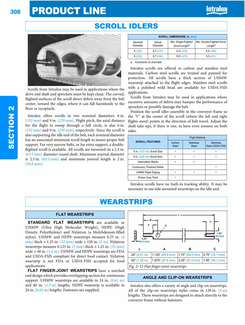
308 PRODUCT LINES
EC
TIO
N 2
Scrolls from Intralox may be used in applications where thedrive end shaft and sprockets must be kept clean. The curved,flighted surfaces of the scroll direct debris away from the beltcenter, toward the edges, where it can fall harmlessly to thefloor or receptacle.
Intralox offers scrolls in two nominal diameters: 6 in.(152 mm) and 9 in. (229 mm). Flight pitch, the axial distancefor the flight to sweep through a full circle, is also 6 in.(152 mm) and 9 in. (229 mm), respectively. Since the scroll isalso supporting the idle end of the belt, each nominal diameterhas an associated minimum scroll length to insure proper beltsupport. For very narrow belts, or for extra support, a double-flighted scroll is available. All scrolls are mounted on a 2.5 in.(63.5 mm) diameter round shaft. Maximum journal diameteris 2.5 in. (63.5 mm) and minimum journal length is 2 in.(50.8 mm).
Intralox scrolls are offered in carbon and stainless steelmaterials. Carbon steel scrolls are treated and painted forprotection. All scrolls have a thick section of UHMWwearstrip attached to the flight edges. Stainless steel scrollswith a polished weld bead are available for USDA-FSISapplications.
Scrolls from Intralox may be used in applications whereexcessive amounts of debris may hamper the performance ofsprockets or possibly damage the belt.
Position the scroll idler assembly in the conveyor frame sothe "V" at the center of the scroll (where the left and rightflights meet) points in the direction of belt travel. Adjust theshaft take-ups, if there is one, to have even tension on bothsides.
Intralox scrolls have no built-in tracking ability. It may benecessary to use side mounted wearstrips on the idle end.
STANDARD FLAT WEARSTRIPS are available inUHMW (Ultra High Molecular Weight), HDPE (HighDensity Polyethylene) and Nylatron (a Molybdenum-fillednylon). UHMW and HDPE wearstrips measure 0.25 in. (6mm) thick × 1.25 in. (32 mm) wide × 120 in. (3 m). Nylatronwearstrips measure 0.125 in. (3 mm) thick × 1.25 in. (32 mm)wide × 48 in. (1.2 m). UHMW and HDPE wearstrips are FDAand USDA-FSIS compliant for direct food contact. Nylatronwearstrip is not FDA or USDA-FSIS accepted for foodapplications.
FLAT FINGER-JOINT WEARSTRIPS have a notchedend design which provides overlapping section for continuoussupport. UHMW wearstrips are available in 24 in. (0.61 m)and 60 in. (1.5 m) lengths. HDPE wearstrip is available in24 in. (0.61 m) lengths. Fasteners are supplied.
Intralox also offers a variety of angle and clip-on wearstrips.All of the clip-on wearstrips styles come in 120 in. (3 m)lengths. These wearstrips are designed to attach directly to theconveyor frame without fasteners.
SCROLL IDLERSSCROLL DIMENSIONS, in. (mm)
Nominal Diameter
ActualDiameter
Min. Single-Flighted Scroll Lengtha
a. Exclusive of Journals.
Min. Double-Flighted Scroll Lengtha
6 (152) 6.7 (170) 12.5 (318) 6.5 (165)
9 (229) 9.7 (246) 18.5 (470) 9.5 (241)
SCROLL FEATURESFlight Material
CarbonSteel
StainlessSteel
StainlessSteel USDA-FSIS
6 in. (152 mm) Scroll Size • • •
9 in. (229 mm) Scroll Size • • •
Intermittent Welds • •
Continuous, Polished Welds •
UHMW Flight Edging • • •
Primer Gray Paint •
WEARSTRIPSFLAT WEARSTRIPS
L A B C
24” (0.61 m) 1.125” (28.6 mm) 1.75” (44.5 mm) 0.75” (19.1 mm)
60” (1.52 m) 1.875” (47.6 mm) 2.25” (57.2 mm) 1.50” (38.1 mm)
Fig. 2–15 Flat finger-joint wearstrips
ANGLE AND CLIP-ON WEARSTRIPS
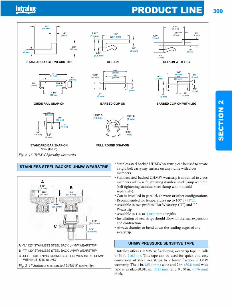
PRODUCT LINE 309
SE
CT
ION
2
• Stainless steel backed UHMW wearstrip can be used to create a rigid belt carryway surface on any frame with cross members.
• Stainless steel backed UHMW wearstrip is mounted to cross members with a self tightening stainless steel clamp with nut (self tightening stainless steel clamp with nut sold separately).
• Can be installed in parallel, chevron or other configurations.• Recommended for temperatures up to 160°F (71°C).• Available in two profiles: Flat Wearstrip ("T") and "L"
Wearstrip• Available in 120 in. (3048 mm) lengths.• Installation of wearstrips should allow for thermal expansion
and contraction.• Always chamfer or bend down the leading edges of any
wearstrip.
Intralox offers UHMW self-adhering wearstrip tape in rollsof 54 ft. (16.5 m). This tape can be used for quick and easyconversion of steel wearstrips to a lower friction UHMWwearstrip. The 1 in. (25.4 mm) wide and 2 in. (50.8 mm) widetape is available0.010 in. (0.25 mm) and 0.030 in. (0.76 mm)thick.
STANDARD ANGLE WEARSTRIP CLIP-ON CLIP-ON WITH LEG
GUIDE RAIL SNAP-ON BARBED CLIP-ON BARBED CLIP-ON WITH LEG
STANDARD BAR SNAP-ON*min. (toe in)
FULL ROUND SNAP-ON
Fig. 2–16 UHMW Specialty wearstrips
STAINLESS STEEL BACKED UHMW WEARSTRIP
A - "L" 120" STAINLESS STEEL BACK UHMW WEARSTRIP
B - "T" 120" STAINLESS STEEL BACK UHMW WEARSTRIP
C - SELF TIGHTENING STAINLESS STEEL WEARSTRIP CLAMP WITH NUT -5/16-18 UNC
Fig. 2–17 Stainless steel backed UHMW wearstrips
UHMW PRESSURE SENSITIVE TAPE
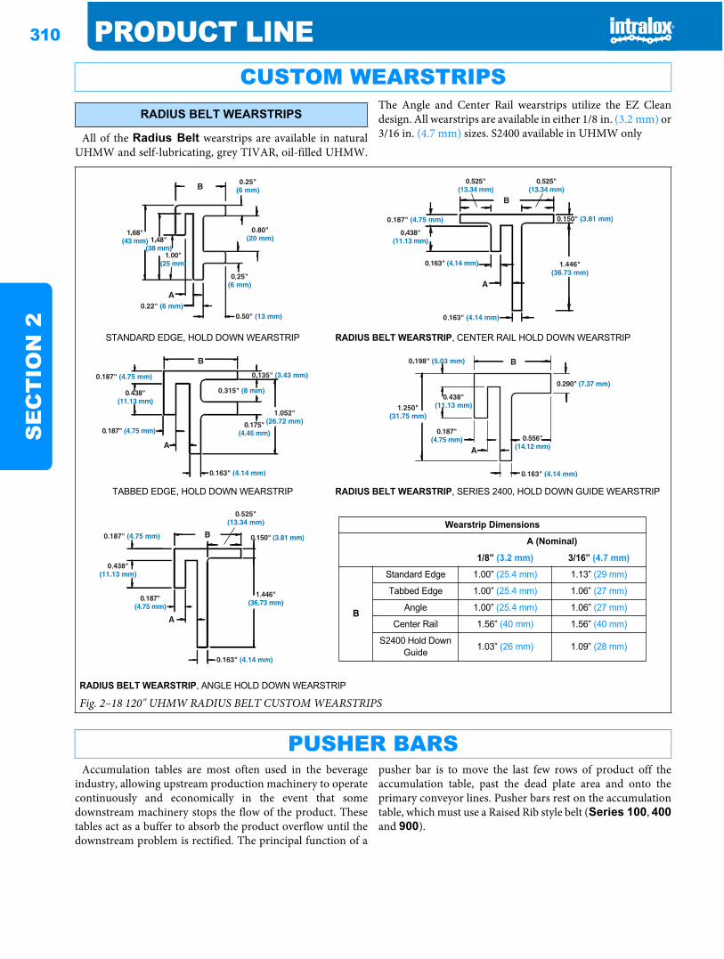
310 PRODUCT LINES
EC
TIO
N 2
All of the Radius Belt wearstrips are available in naturalUHMW and self-lubricating, grey TIVAR, oil-filled UHMW.
The Angle and Center Rail wearstrips utilize the EZ Cleandesign. All wearstrips are available in either 1/8 in. (3.2 mm) or3/16 in. (4.7 mm) sizes. S2400 available in UHMW only
Accumulation tables are most often used in the beverageindustry, allowing upstream production machinery to operatecontinuously and economically in the event that somedownstream machinery stops the flow of the product. Thesetables act as a buffer to absorb the product overflow until thedownstream problem is rectified. The principal function of a
pusher bar is to move the last few rows of product off theaccumulation table, past the dead plate area and onto theprimary conveyor lines. Pusher bars rest on the accumulationtable, which must use a Raised Rib style belt (Series 100, 400and 900).
CUSTOM WEARSTRIPSRADIUS BELT WEARSTRIPS
STANDARD EDGE, HOLD DOWN WEARSTRIP RADIUS BELT WEARSTRIP, CENTER RAIL HOLD DOWN WEARSTRIP
TABBED EDGE, HOLD DOWN WEARSTRIP RADIUS BELT WEARSTRIP, SERIES 2400, HOLD DOWN GUIDE WEARSTRIP
Wearstrip Dimensions
A (Nominal)
1/8” (3.2 mm) 3/16” (4.7 mm)
B
Standard Edge 1.00” (25.4 mm) 1.13” (29 mm)
Tabbed Edge 1.00” (25.4 mm) 1.06” (27 mm)
Angle 1.00” (25.4 mm) 1.06” (27 mm)
Center Rail 1.56” (40 mm) 1.56” (40 mm)
S2400 Hold Down Guide 1.03” (26 mm) 1.09” (28 mm)
RADIUS BELT WEARSTRIP, ANGLE HOLD DOWN WEARSTRIP
Fig. 2–18 120" UHMW RADIUS BELT CUSTOM WEARSTRIPS
PUSHER BARS
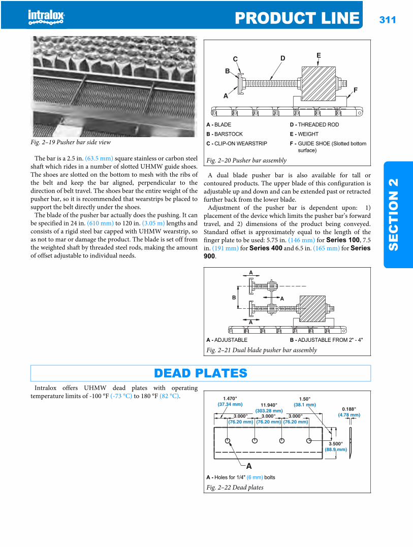
PRODUCT LINE 311
SE
CT
ION
2
Fig. 2–19 Pusher bar side view
The bar is a 2.5 in. (63.5 mm) square stainless or carbon steelshaft which rides in a number of slotted UHMW guide shoes.The shoes are slotted on the bottom to mesh with the ribs ofthe belt and keep the bar aligned, perpendicular to thedirection of belt travel. The shoes bear the entire weight of thepusher bar, so it is recommended that wearstrips be placed tosupport the belt directly under the shoes.
The blade of the pusher bar actually does the pushing. It canbe specified in 24 in. (610 mm) to 120 in. (3.05 m) lengths andconsists of a rigid steel bar capped with UHMW wearstrip, soas not to mar or damage the product. The blade is set off fromthe weighted shaft by threaded steel rods, making the amountof offset adjustable to individual needs.
A dual blade pusher bar is also available for tall orcontoured products. The upper blade of this configuration isadjustable up and down and can be extended past or retractedfurther back from the lower blade.
Adjustment of the pusher bar is dependent upon: 1)placement of the device which limits the pusher bar’s forwardtravel, and 2) dimensions of the product being conveyed.Standard offset is approximately equal to the length of thefinger plate to be used: 5.75 in. (146 mm) for Series 100, 7.5in. (191 mm) for Series 400 and 6.5 in. (165 mm) for Series900.
Intralox offers UHMW dead plates with operatingtemperature limits of -100 °F (-73 °C) to 180 °F (82 °C).
A - BLADE D - THREADED ROD
B - BARSTOCK E - WEIGHT
C - CLIP-ON WEARSTRIP F - GUIDE SHOE (Slotted bottom surface)
Fig. 2–20 Pusher bar assembly
A - ADJUSTABLE B - ADJUSTABLE FROM 2" - 4"
Fig. 2–21 Dual blade pusher bar assembly
DEAD PLATES
A - Holes for 1/4" (6 mm) bolts
Fig. 2–22 Dead plates
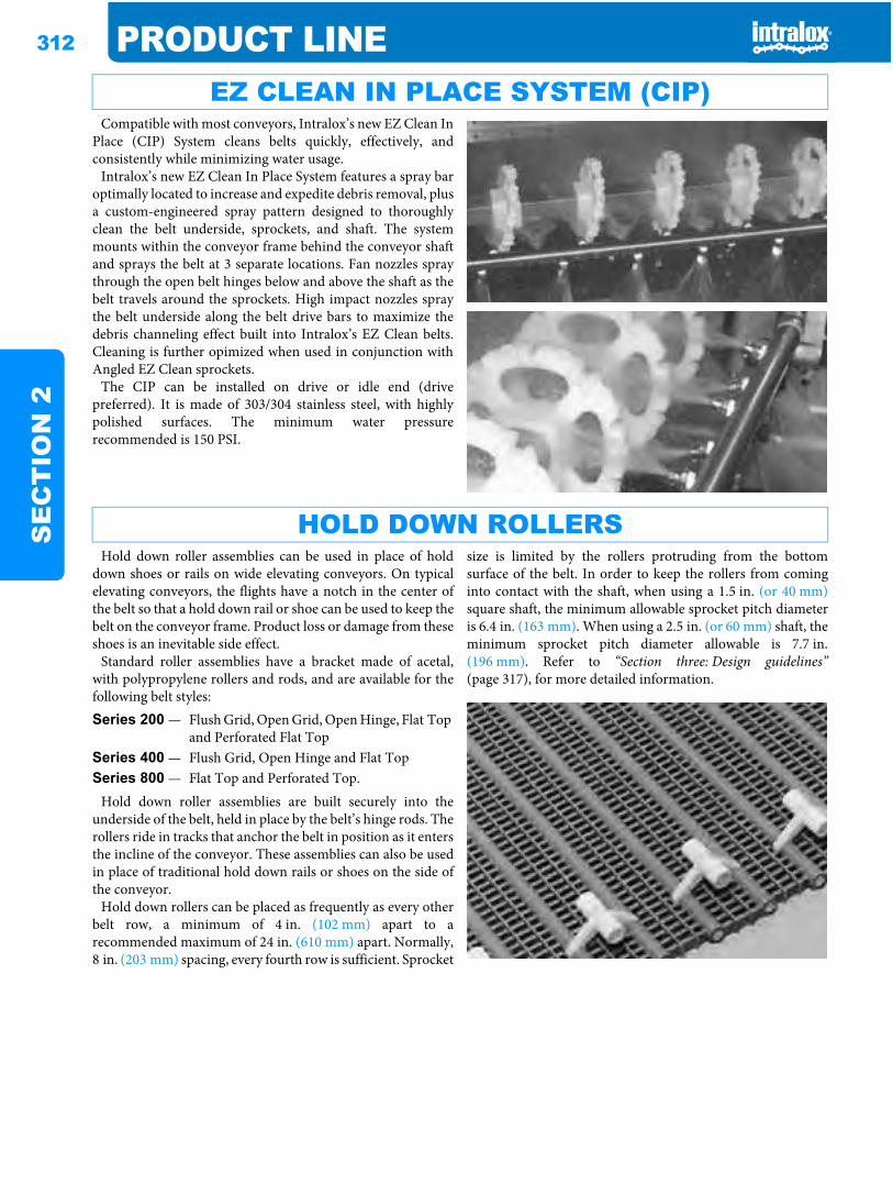
312 PRODUCT LINES
EC
TIO
N 2
Compatible with most conveyors, Intralox’s new EZ Clean InPlace (CIP) System cleans belts quickly, effectively, andconsistently while minimizing water usage.
Intralox’s new EZ Clean In Place System features a spray baroptimally located to increase and expedite debris removal, plusa custom-engineered spray pattern designed to thoroughlyclean the belt underside, sprockets, and shaft. The systemmounts within the conveyor frame behind the conveyor shaftand sprays the belt at 3 separate locations. Fan nozzles spraythrough the open belt hinges below and above the shaft as thebelt travels around the sprockets. High impact nozzles spraythe belt underside along the belt drive bars to maximize thedebris channeling effect built into Intralox’s EZ Clean belts.Cleaning is further opimized when used in conjunction withAngled EZ Clean sprockets.
The CIP can be installed on drive or idle end (drivepreferred). It is made of 303/304 stainless steel, with highlypolished surfaces. The minimum water pressurerecommended is 150 PSI.
Hold down roller assemblies can be used in place of holddown shoes or rails on wide elevating conveyors. On typicalelevating conveyors, the flights have a notch in the center ofthe belt so that a hold down rail or shoe can be used to keep thebelt on the conveyor frame. Product loss or damage from theseshoes is an inevitable side effect.
Standard roller assemblies have a bracket made of acetal,with polypropylene rollers and rods, and are available for thefollowing belt styles:
Hold down roller assemblies are built securely into theunderside of the belt, held in place by the belt’s hinge rods. Therollers ride in tracks that anchor the belt in position as it entersthe incline of the conveyor. These assemblies can also be usedin place of traditional hold down rails or shoes on the side ofthe conveyor.
Hold down rollers can be placed as frequently as every otherbelt row, a minimum of 4 in. (102 mm) apart to arecommended maximum of 24 in. (610 mm) apart. Normally,8 in. (203 mm) spacing, every fourth row is sufficient. Sprocket
size is limited by the rollers protruding from the bottomsurface of the belt. In order to keep the rollers from cominginto contact with the shaft, when using a 1.5 in. (or 40 mm)square shaft, the minimum allowable sprocket pitch diameteris 6.4 in. (163 mm). When using a 2.5 in. (or 60 mm) shaft, theminimum sprocket pitch diameter allowable is 7.7 in.(196 mm). Refer to “Section three: Design guidelines”(page 317), for more detailed information.
EZ CLEAN IN PLACE SYSTEM (CIP)
HOLD DOWN ROLLERS
Series 200 — Flush Grid, Open Grid, Open Hinge, Flat Top and Perforated Flat Top
Series 400 — Flush Grid, Open Hinge and Flat TopSeries 800 — Flat Top and Perforated Top.
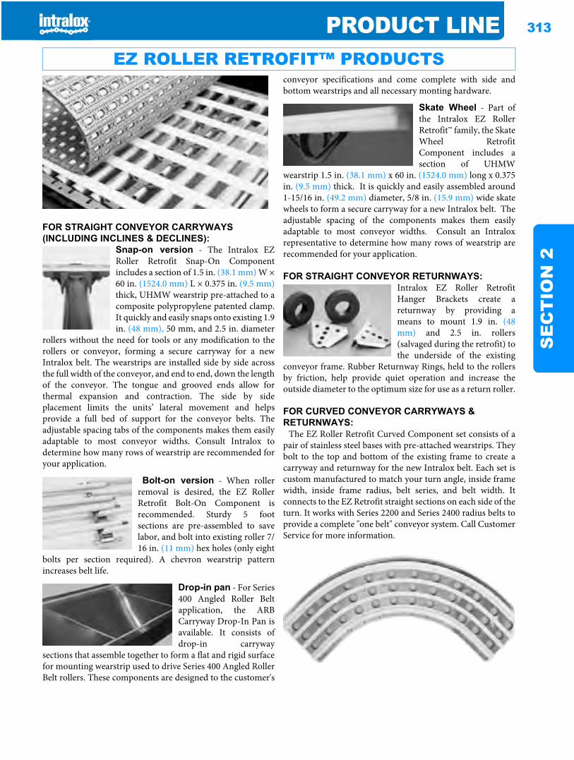
PRODUCT LINE 313
SE
CT
ION
2
FOR STRAIGHT CONVEYOR CARRYWAYS (INCLUDING INCLINES & DECLINES):
Snap-on version - The Intralox EZRoller Retrofit Snap-On Componentincludes a section of 1.5 in. (38.1 mm) W ×60 in. (1524.0 mm) L × 0.375 in. (9.5 mm)thick, UHMW wearstrip pre-attached to acomposite polypropylene patented clamp.It quickly and easily snaps onto existing 1.9in. (48 mm), 50 mm, and 2.5 in. diameter
rollers without the need for tools or any modification to therollers or conveyor, forming a secure carryway for a newIntralox belt. The wearstrips are installed side by side acrossthe full width of the conveyor, and end to end, down the lengthof the conveyor. The tongue and grooved ends allow forthermal expansion and contraction. The side by sideplacement limits the units’ lateral movement and helpsprovide a full bed of support for the conveyor belts. Theadjustable spacing tabs of the components makes them easilyadaptable to most conveyor widths. Consult Intralox todetermine how many rows of wearstrip are recommended foryour application.
Bolt-on version - When rollerremoval is desired, the EZ RollerRetrofit Bolt-On Component isrecommended. Sturdy 5 footsections are pre-assembled to savelabor, and bolt into existing roller 7/16 in. (11 mm) hex holes (only eight
bolts per section required). A chevron wearstrip patternincreases belt life.
Drop-in pan - For Series400 Angled Roller Beltapplication, the ARBCarryway Drop-In Pan isavailable. It consists ofdrop-in carryway
sections that assemble together to form a flat and rigid surfacefor mounting wearstrip used to drive Series 400 Angled RollerBelt rollers. These components are designed to the customer's
conveyor specifications and come complete with side andbottom wearstrips and all necessary monting hardware.
Skate Wheel - Part ofthe Intralox EZ RollerRetrofit™ family, the SkateWheel RetrofitComponent includes asection of UHMW
wearstrip 1.5 in. (38.1 mm) x 60 in. (1524.0 mm) long x 0.375in. (9.5 mm) thick. It is quickly and easily assembled around1-15/16 in. (49.2 mm) diameter, 5/8 in. (15.9 mm) wide skatewheels to form a secure carryway for a new Intralox belt. Theadjustable spacing of the components makes them easilyadaptable to most conveyor widths. Consult an Intraloxrepresentative to determine how many rows of wearstrip arerecommended for your application.
FOR STRAIGHT CONVEYOR RETURNWAYS:Intralox EZ Roller RetrofitHanger Brackets create areturnway by providing ameans to mount 1.9 in. (48mm) and 2.5 in. rollers(salvaged during the retrofit) tothe underside of the existing
conveyor frame. Rubber Returnway Rings, held to the rollersby friction, help provide quiet operation and increase theoutside diameter to the optimum size for use as a return roller.
FOR CURVED CONVEYOR CARRYWAYS & RETURNWAYS:
The EZ Roller Retrofit Curved Component set consists of apair of stainless steel bases with pre-attached wearstrips. Theybolt to the top and bottom of the existing frame to create acarryway and returnway for the new Intralox belt. Each set iscustom manufactured to match your turn angle, inside framewidth, inside frame radius, belt series, and belt width. Itconnects to the EZ Retrofit straight sections on each side of theturn. It works with Series 2200 and Series 2400 radius belts toprovide a complete "one belt" conveyor system. Call CustomerService for more information.
EZ ROLLER RETROFIT™ PRODUCTS
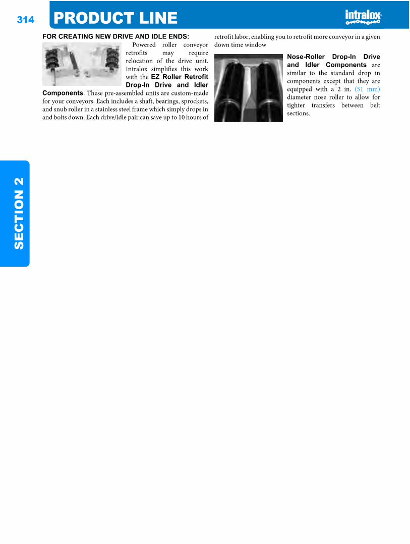
314 PRODUCT LINES
EC
TIO
N 2
FOR CREATING NEW DRIVE AND IDLE ENDS: Powered roller conveyorretrofits may requirerelocation of the drive unit.Intralox simplifies this workwith the EZ Roller RetrofitDrop-In Drive and Idler
Components. These pre-assembled units are custom-madefor your conveyors. Each includes a shaft, bearings, sprockets,and snub roller in a stainless steel frame which simply drops inand bolts down. Each drive/idle pair can save up to 10 hours of
retrofit labor, enabling you to retrofit more conveyor in a givendown time window
Nose-Roller Drop-In Driveand Idler Components aresimilar to the standard drop incomponents except that they areequipped with a 2 in. (51 mm)diameter nose roller to allow fortighter transfers between beltsections.
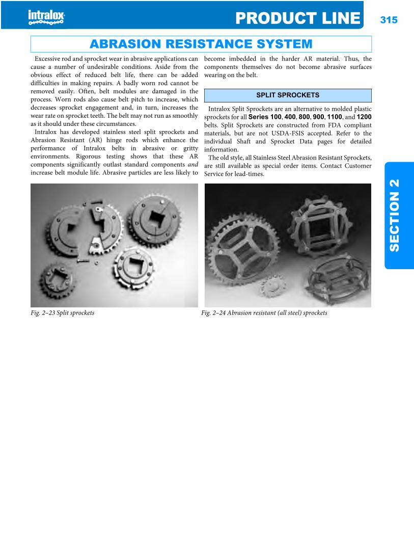
PRODUCT LINE 315
SE
CT
ION
2
Excessive rod and sprocket wear in abrasive applications cancause a number of undesirable conditions. Aside from theobvious effect of reduced belt life, there can be addeddifficulties in making repairs. A badly worn rod cannot beremoved easily. Often, belt modules are damaged in theprocess. Worn rods also cause belt pitch to increase, whichdecreases sprocket engagement and, in turn, increases thewear rate on sprocket teeth. The belt may not run as smoothlyas it should under these circumstances.
Intralox has developed stainless steel split sprockets andAbrasion Resistant (AR) hinge rods which enhance theperformance of Intralox belts in abrasive or grittyenvironments. Rigorous testing shows that these ARcomponents significantly outlast standard components andincrease belt module life. Abrasive particles are less likely to
become imbedded in the harder AR material. Thus, thecomponents themselves do not become abrasive surfaceswearing on the belt.
Intralox Split Sprockets are an alternative to molded plasticsprockets for all Series 100, 400, 800, 900, 1100, and 1200belts. Split Sprockets are constructed from FDA compliantmaterials, but are not USDA-FSIS accepted. Refer to theindividual Shaft and Sprocket Data pages for detailedinformation.
The old style, all Stainless Steel Abrasion Resistant Sprockets,are still available as special order items. Contact CustomerService for lead-times.
ABRASION RESISTANCE SYSTEM
SPLIT SPROCKETS
Fig. 2–23 Split sprockets Fig. 2–24 Abrasion resistant (all steel) sprockets
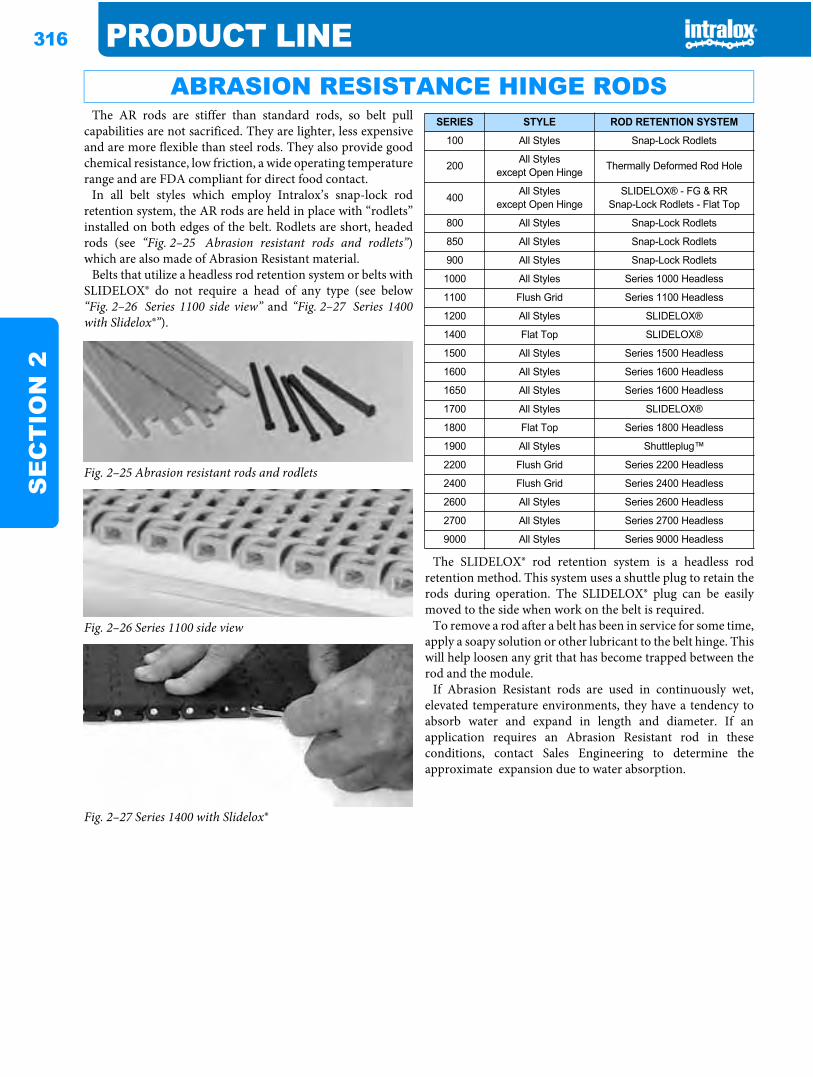
316 PRODUCT LINES
EC
TIO
N 2
The AR rods are stiffer than standard rods, so belt pullcapabilities are not sacrificed. They are lighter, less expensiveand are more flexible than steel rods. They also provide goodchemical resistance, low friction, a wide operating temperaturerange and are FDA compliant for direct food contact.
In all belt styles which employ Intralox’s snap-lock rodretention system, the AR rods are held in place with “rodlets”installed on both edges of the belt. Rodlets are short, headedrods (see “Fig. 2–25 Abrasion resistant rods and rodlets”)which are also made of Abrasion Resistant material.
Belts that utilize a headless rod retention system or belts withSLIDELOX® do not require a head of any type (see below“Fig. 2–26 Series 1100 side view” and “Fig. 2–27 Series 1400with Slidelox®”).
The SLIDELOX® rod retention system is a headless rodretention method. This system uses a shuttle plug to retain therods during operation. The SLIDELOX® plug can be easilymoved to the side when work on the belt is required.
To remove a rod after a belt has been in service for some time,apply a soapy solution or other lubricant to the belt hinge. Thiswill help loosen any grit that has become trapped between therod and the module.
If Abrasion Resistant rods are used in continuously wet,elevated temperature environments, they have a tendency toabsorb water and expand in length and diameter. If anapplication requires an Abrasion Resistant rod in theseconditions, contact Sales Engineering to determine theapproximate expansion due to water absorption.
ABRASION RESISTANCE HINGE RODS
Fig. 2–25 Abrasion resistant rods and rodlets
Fig. 2–26 Series 1100 side view
Fig. 2–27 Series 1400 with Slidelox®
SERIES STYLE ROD RETENTION SYSTEM
100 All Styles Snap-Lock Rodlets
200 All Stylesexcept Open Hinge Thermally Deformed Rod Hole
400 All Stylesexcept Open Hinge
SLIDELOX® - FG & RRSnap-Lock Rodlets - Flat Top
800 All Styles Snap-Lock Rodlets
850 All Styles Snap-Lock Rodlets
900 All Styles Snap-Lock Rodlets
1000 All Styles Series 1000 Headless
1100 Flush Grid Series 1100 Headless
1200 All Styles SLIDELOX®
1400 Flat Top SLIDELOX®
1500 All Styles Series 1500 Headless
1600 All Styles Series 1600 Headless
1650 All Styles Series 1600 Headless
1700 All Styles SLIDELOX®
1800 Flat Top Series 1800 Headless
1900 All Styles Shuttleplug™
2200 Flush Grid Series 2200 Headless
2400 Flush Grid Series 2400 Headless
2600 All Styles Series 2600 Headless
2700 All Styles Series 2700 Headless
9000 All Styles Series 9000 Headless
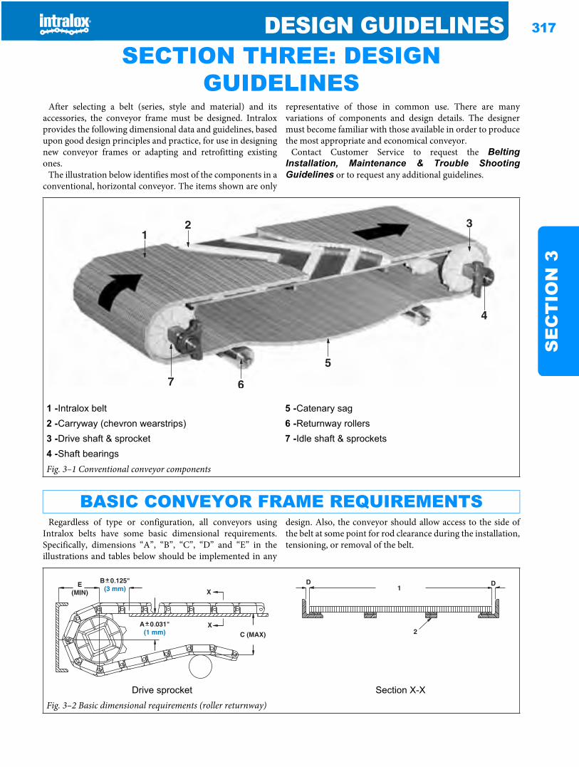
DESIGN GUIDELINES 317
SE
CT
ION
3
Design guidelines SECTION THREE: DESIGN GUIDELINES
After selecting a belt (series, style and material) and itsaccessories, the conveyor frame must be designed. Intraloxprovides the following dimensional data and guidelines, basedupon good design principles and practice, for use in designingnew conveyor frames or adapting and retrofitting existingones.
The illustration below identifies most of the components in aconventional, horizontal conveyor. The items shown are only
representative of those in common use. There are manyvariations of components and design details. The designermust become familiar with those available in order to producethe most appropriate and economical conveyor.
Contact Customer Service to request the BeltingInstallation, Maintenance & Trouble ShootingGuidelines or to request any additional guidelines.
Regardless of type or configuration, all conveyors usingIntralox belts have some basic dimensional requirements.Specifically, dimensions “A”, “B”, “C”, “D” and “E” in theillustrations and tables below should be implemented in any
design. Also, the conveyor should allow access to the side ofthe belt at some point for rod clearance during the installation,tensioning, or removal of the belt.
1 -Intralox belt 5 -Catenary sag2 -Carryway (chevron wearstrips) 6 -Returnway rollers3 -Drive shaft & sprocket 7 -Idle shaft & sprockets4 -Shaft bearingsFig. 3–1 Conventional conveyor components
BASIC CONVEYOR FRAME REQUIREMENTS
1 - Belt width at maximum temperature2 - Intermediate supports3 - Wearstrips
Drive sprocket Section X-XFig. 3–2 Basic dimensional requirements (roller returnway)
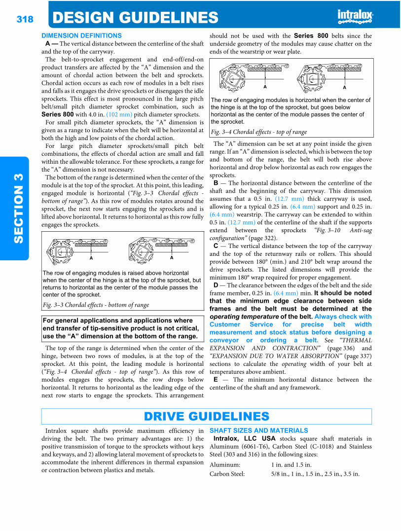
318 DESIGN GUIDELINESS
EC
TIO
N 3
DIMENSION DEFINITIONSA — The vertical distance between the centerline of the shaft
and the top of the carryway.The belt-to-sprocket engagement and end-off/end-on
product transfers are affected by the “A” dimension and theamount of chordal action between the belt and sprockets.Chordal action occurs as each row of modules in a belt risesand falls as it engages the drive sprockets or disengages the idlesprockets. This effect is most pronounced in the large pitchbelt/small pitch diameter sprocket combination, such asSeries 800 with 4.0 in. (102 mm) pitch diameter sprockets.
For small pitch diameter sprockets, the “A” dimension isgiven as a range to indicate when the belt will be horizontal atboth the high and low points of the chordal action.
For large pitch diameter sprockets/small pitch beltcombinations, the effects of chordal action are small and fallwithin the allowable tolerance. For these sprockets, a range forthe “A” dimension is not necessary.
The bottom of the range is determined when the center of themodule is at the top of the sprocket. At this point, this leading,engaged module is horizontal (“Fig. 3–3 Chordal effects -bottom of range”). As this row of modules rotates around thesprocket, the next row starts engaging the sprockets and islifted above horizontal. It returns to horizontal as this row fullyengages the sprockets.
The top of the range is determined when the center of thehinge, between two rows of modules, is at the top of thesprocket. At this point, the leading module is horizontal(“Fig. 3–4 Chordal effects - top of range”). As this row ofmodules engages the sprockets, the row drops belowhorizontal. It returns to horizontal as the leading edge of thenext row starts to engage the sprockets. This arrangement
should not be used with the Series 800 belts since theunderside geometry of the modules may cause chatter on theends of the wearstrip or wear plate.
The “A” dimension can be set at any point inside the givenrange. If an “A” dimension is selected, which is between the topand bottom of the range, the belt will both rise abovehorizontal and drop below horizontal as each row engages thesprockets.
B — The horizontal distance between the centerline of theshaft and the beginning of the carryway. This dimensionassumes that a 0.5 in. (12.7 mm) thick carryway is used,allowing for a typical 0.25 in. (6.4 mm) support and 0.25 in.(6.4 mm) wearstrip. The carryway can be extended to within0.5 in. (12.7 mm) of the centerline of the shaft if the supportsextend between the sprockets “Fig. 3–10 Anti-sagconfiguration” (page 322).
C — The vertical distance between the top of the carrywayand the top of the returnway rails or rollers. This shouldprovide between 180° (min.) and 210° belt wrap around thedrive sprockets. The listed dimensions will provide theminimum 180° wrap required for proper engagement.
D — The clearance between the edges of the belt and the sideframe member, 0.25 in. (6.4 mm) min. It should be notedthat the minimum edge clearance between sideframes and the belt must be determined at theoperating temperature of the belt. Always check withCustomer Service for precise belt widthmeasurement and stock status before designing aconveyor or ordering a belt. See “THERMALEXPANSION AND CONTRACTION” (page 336) and“EXPANSION DUE TO WATER ABSORPTION” (page 337)sections to calculate the operating width of your belt attemperatures above ambient.
E — The minimum horizontal distance between thecenterline of the shaft and any framework.
Intralox square shafts provide maximum efficiency indriving the belt. The two primary advantages are: 1) thepositive transmission of torque to the sprockets without keysand keyways, and 2) allowing lateral movement of sprockets toaccommodate the inherent differences in thermal expansionor contraction between plastics and metals.
SHAFT SIZES AND MATERIALSIntralox, LLC USA stocks square shaft materials in
Aluminum (6061-T6), Carbon Steel (C-1018) and StainlessSteel (303 and 316) in the following sizes:
A - (Bottom of range) A - (Bottom of range)
The row of engaging modules is raised above horizontal when the center of the hinge is at the top of the sprocket, but returns to horizontal as the center of the module passes the center of the sprocket.
Fig. 3–3 Chordal effects - bottom of range
For general applications and applications where end transfer of tip-sensitive product is not critical, use the “A” dimension at the bottom of the range.
A - (Top of range) A - (Top of range)
The row of engaging modules is horizontal when the center of the hinge is at the top of the sprocket, but goes below horizontal as the center of the module passes the center of the sprocket.
Fig. 3–4 Chordal effects - top of range
DRIVE GUIDELINES
Aluminum: 1 in. and 1.5 in. Carbon Steel: 5/8 in., 1 in., 1.5 in., 2.5 in., 3.5 in.
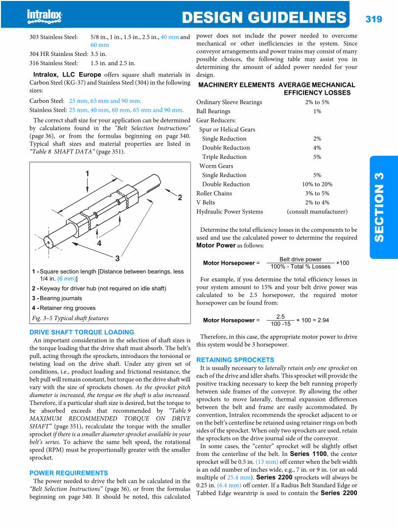
DESIGN GUIDELINES 319
SE
CT
ION
3
Intralox, LLC Europe offers square shaft materials inCarbon Steel (KG-37) and Stainless Steel (304) in the followingsizes:
The correct shaft size for your application can be determinedby calculations found in the “Belt Selection Instructions”(page 36), or from the formulas beginning on page 340.Typical shaft sizes and material properties are listed in“Table 8 SHAFT DATA” (page 351).
DRIVE SHAFT TORQUE LOADINGAn important consideration in the selection of shaft sizes is
the torque loading that the drive shaft must absorb. The belt’spull, acting through the sprockets, introduces the torsional ortwisting load on the drive shaft. Under any given set ofconditions, i.e., product loading and frictional resistance, thebelt pull will remain constant, but torque on the drive shaft willvary with the size of sprockets chosen. As the sprocket pitchdiameter is increased, the torque on the shaft is also increased.Therefore, if a particular shaft size is desired, but the torque tobe absorbed exceeds that recommended by “Table 9MAXIMUM RECOMMENDED TORQUE ON DRIVESHAFT” (page 351), recalculate the torque with the smallersprocket if there is a smaller diameter sprocket available in yourbelt’s series. To achieve the same belt speed, the rotationalspeed (RPM) must be proportionally greater with the smallersprocket.
POWER REQUIREMENTSThe power needed to drive the belt can be calculated in the
“Belt Selection Instructions” (page 36), or from the formulasbeginning on page 340. It should be noted, this calculated
power does not include the power needed to overcomemechanical or other inefficiencies in the system. Sinceconveyor arrangements and power trains may consist of manypossible choices, the following table may assist you indetermining the amount of added power needed for yourdesign.
Determine the total efficiency losses in the components to beused and use the calculated power to determine the requiredMotor Power as follows:
For example, if you determine the total efficiency losses inyour system amount to 15% and your belt drive power wascalculated to be 2.5 horsepower, the required motorhorsepower can be found from:
Therefore, in this case, the appropriate motor power to drivethis system would be 3 horsepower.
RETAINING SPROCKETSIt is usually necessary to laterally retain only one sprocket on
each of the drive and idler shafts. This sprocket will provide thepositive tracking necessary to keep the belt running properlybetween side frames of the conveyor. By allowing the othersprockets to move laterally, thermal expansion differencesbetween the belt and frame are easily accommodated. Byconvention, Intralox recommends the sprocket adjacent to oron the belt’s centerline be retained using retainer rings on bothsides of the sprocket. When only two sprockets are used, retainthe sprockets on the drive journal side of the conveyor.
In some cases, the “center” sprocket will be slightly offsetfrom the centerline of the belt. In Series 1100, the centersprocket will be 0.5 in. (13 mm) off center when the belt widthis an odd number of inches wide, e.g., 7 in. or 9 in. (or an oddmultiple of 25.4 mm). Series 2200 sprockets will always be0.25 in. (6.4 mm) off center. If a Radius Belt Standard Edge orTabbed Edge wearstrip is used to contain the Series 2200
303 Stainless Steel: 5/8 in., 1 in., 1.5 in., 2.5 in., 40 mm and 60 mm
304 HR Stainless Steel: 3.5 in.316 Stainless Steel: 1.5 in. and 2.5 in.
Carbon Steel: 25 mm, 65 mm and 90 mm.Stainless Steel: 25 mm, 40 mm, 60 mm, 65 mm and 90 mm.
1 - Square section length [Distance between bearings, less 1/4 in. (6 mm)]
2 - Keyway for driver hub (not required on idle shaft)
3 - Bearing journals
4 - Retainer ring grooves
Fig. 3–5 Typical shaft features
MACHINERY ELEMENTS AVERAGE MECHANICAL EFFICIENCY LOSSES
Ordinary Sleeve Bearings 2% to 5%Ball Bearings 1%Gear Reducers:
Spur or Helical Gears Single Reduction 2%Double Reduction 4%Triple Reduction 5%
Worm GearsSingle Reduction 5%Double Reduction 10% to 20%
Roller Chains 3% to 5%V Belts 2% to 4%Hydraulic Power Systems (consult manufacturer)
Motor Horsepower = Belt drive power ×100100% - Total % Losses
Motor Horsepower = 2.5 × 100 = 2.94100 -15
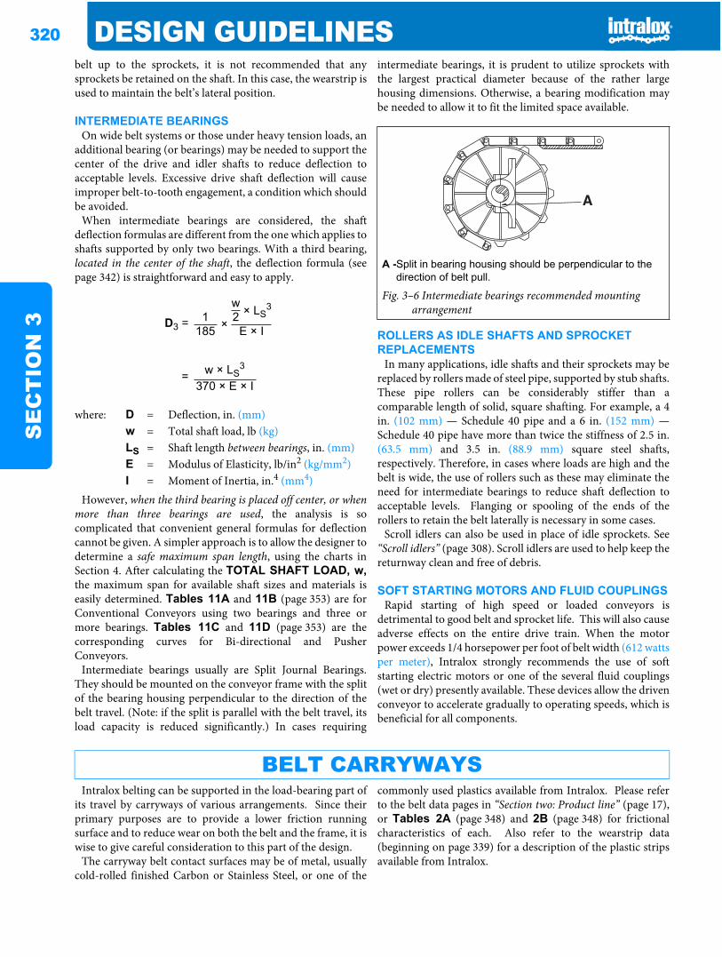
320 DESIGN GUIDELINESS
EC
TIO
N 3
belt up to the sprockets, it is not recommended that anysprockets be retained on the shaft. In this case, the wearstrip isused to maintain the belt’s lateral position.
INTERMEDIATE BEARINGSOn wide belt systems or those under heavy tension loads, an
additional bearing (or bearings) may be needed to support thecenter of the drive and idler shafts to reduce deflection toacceptable levels. Excessive drive shaft deflection will causeimproper belt-to-tooth engagement, a condition which shouldbe avoided.
When intermediate bearings are considered, the shaftdeflection formulas are different from the one which applies toshafts supported by only two bearings. With a third bearing,located in the center of the shaft, the deflection formula (seepage 342) is straightforward and easy to apply.
However, when the third bearing is placed off center, or whenmore than three bearings are used, the analysis is socomplicated that convenient general formulas for deflectioncannot be given. A simpler approach is to allow the designer todetermine a safe maximum span length, using the charts inSection 4. After calculating the TOTAL SHAFT LOAD, w,the maximum span for available shaft sizes and materials iseasily determined. Tables 11A and 11B (page 353) are forConventional Conveyors using two bearings and three ormore bearings. Tables 11C and 11D (page 353) are thecorresponding curves for Bi-directional and PusherConveyors.
Intermediate bearings usually are Split Journal Bearings.They should be mounted on the conveyor frame with the splitof the bearing housing perpendicular to the direction of thebelt travel. (Note: if the split is parallel with the belt travel, itsload capacity is reduced significantly.) In cases requiring
intermediate bearings, it is prudent to utilize sprockets withthe largest practical diameter because of the rather largehousing dimensions. Otherwise, a bearing modification maybe needed to allow it to fit the limited space available.
ROLLERS AS IDLE SHAFTS AND SPROCKET REPLACEMENTS
In many applications, idle shafts and their sprockets may bereplaced by rollers made of steel pipe, supported by stub shafts.These pipe rollers can be considerably stiffer than acomparable length of solid, square shafting. For example, a 4in. (102 mm) — Schedule 40 pipe and a 6 in. (152 mm) —Schedule 40 pipe have more than twice the stiffness of 2.5 in.(63.5 mm) and 3.5 in. (88.9 mm) square steel shafts,respectively. Therefore, in cases where loads are high and thebelt is wide, the use of rollers such as these may eliminate theneed for intermediate bearings to reduce shaft deflection toacceptable levels. Flanging or spooling of the ends of therollers to retain the belt laterally is necessary in some cases.
Scroll idlers can also be used in place of idle sprockets. See“Scroll idlers” (page 308). Scroll idlers are used to help keep thereturnway clean and free of debris.
SOFT STARTING MOTORS AND FLUID COUPLINGSRapid starting of high speed or loaded conveyors is
detrimental to good belt and sprocket life. This will also causeadverse effects on the entire drive train. When the motorpower exceeds 1/4 horsepower per foot of belt width (612 wattsper meter), Intralox strongly recommends the use of softstarting electric motors or one of the several fluid couplings(wet or dry) presently available. These devices allow the drivenconveyor to accelerate gradually to operating speeds, which isbeneficial for all components.
Intralox belting can be supported in the load-bearing part ofits travel by carryways of various arrangements. Since theirprimary purposes are to provide a lower friction runningsurface and to reduce wear on both the belt and the frame, it iswise to give careful consideration to this part of the design.
The carryway belt contact surfaces may be of metal, usuallycold-rolled finished Carbon or Stainless Steel, or one of the
commonly used plastics available from Intralox. Please referto the belt data pages in “Section two: Product line” (page 17),or Tables 2A (page 348) and 2B (page 348) for frictionalcharacteristics of each. Also refer to the wearstrip data(beginning on page 339) for a description of the plastic stripsavailable from Intralox.
w × LS3
D3 = 1 × 2185 E × I
= w × LS3
370 × E × I
where: D = Deflection, in. (mm)w = Total shaft load, lb (kg)LS = Shaft length between bearings, in. (mm)E = Modulus of Elasticity, lb/in2 (kg/mm2)I = Moment of Inertia, in.4 (mm4)
A -Split in bearing housing should be perpendicular to the direction of belt pull.
Fig. 3–6 Intermediate bearings recommended mounting arrangement
BELT CARRYWAYS
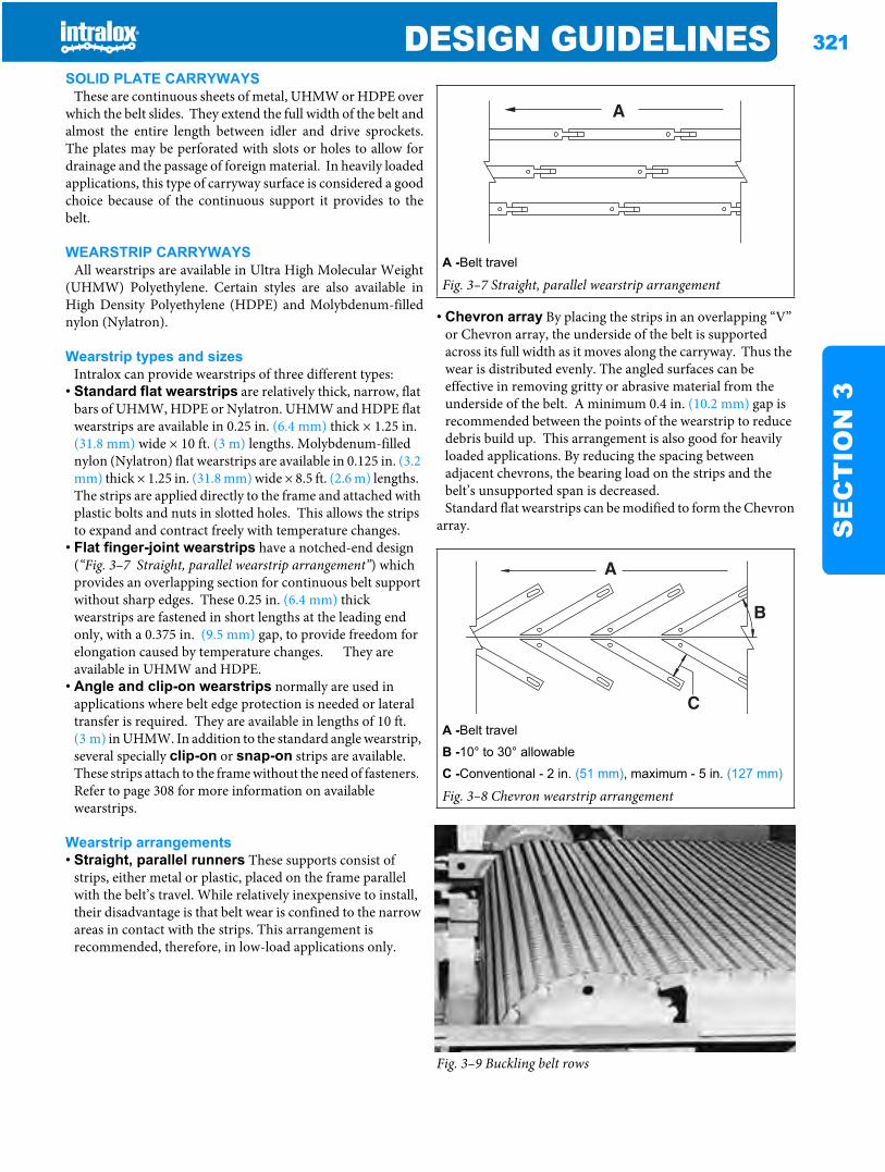
DESIGN GUIDELINES 321
SE
CT
ION
3
SOLID PLATE CARRYWAYSThese are continuous sheets of metal, UHMW or HDPE over
which the belt slides. They extend the full width of the belt andalmost the entire length between idler and drive sprockets.The plates may be perforated with slots or holes to allow fordrainage and the passage of foreign material. In heavily loadedapplications, this type of carryway surface is considered a goodchoice because of the continuous support it provides to thebelt.
WEARSTRIP CARRYWAYSAll wearstrips are available in Ultra High Molecular Weight
(UHMW) Polyethylene. Certain styles are also available inHigh Density Polyethylene (HDPE) and Molybdenum-fillednylon (Nylatron).
Wearstrip types and sizesIntralox can provide wearstrips of three different types:
• Standard flat wearstrips are relatively thick, narrow, flat bars of UHMW, HDPE or Nylatron. UHMW and HDPE flat wearstrips are available in 0.25 in. (6.4 mm) thick × 1.25 in. (31.8 mm) wide × 10 ft. (3 m) lengths. Molybdenum-filled nylon (Nylatron) flat wearstrips are available in 0.125 in. (3.2 mm) thick × 1.25 in. (31.8 mm) wide × 8.5 ft. (2.6 m) lengths. The strips are applied directly to the frame and attached with plastic bolts and nuts in slotted holes. This allows the strips to expand and contract freely with temperature changes.
• Flat finger-joint wearstrips have a notched-end design (“Fig. 3–7 Straight, parallel wearstrip arrangement”) which provides an overlapping section for continuous belt support without sharp edges. These 0.25 in. (6.4 mm) thick wearstrips are fastened in short lengths at the leading end only, with a 0.375 in. (9.5 mm) gap, to provide freedom for elongation caused by temperature changes. They are available in UHMW and HDPE.
• Angle and clip-on wearstrips normally are used in applications where belt edge protection is needed or lateral transfer is required. They are available in lengths of 10 ft. (3 m) in UHMW. In addition to the standard angle wearstrip, several specially clip-on or snap-on strips are available. These strips attach to the frame without the need of fasteners. Refer to page 308 for more information on available wearstrips.
Wearstrip arrangements• Straight, parallel runners These supports consist of
strips, either metal or plastic, placed on the frame parallel with the belt’s travel. While relatively inexpensive to install, their disadvantage is that belt wear is confined to the narrow areas in contact with the strips. This arrangement is recommended, therefore, in low-load applications only.
• Chevron array By placing the strips in an overlapping “V” or Chevron array, the underside of the belt is supported across its full width as it moves along the carryway. Thus the wear is distributed evenly. The angled surfaces can be effective in removing gritty or abrasive material from the underside of the belt. A minimum 0.4 in. (10.2 mm) gap is recommended between the points of the wearstrip to reduce debris build up. This arrangement is also good for heavily loaded applications. By reducing the spacing between adjacent chevrons, the bearing load on the strips and the belt’s unsupported span is decreased.Standard flat wearstrips can be modified to form the Chevron
array.
Fig. 3–9 Buckling belt rows
A -Belt travel
Fig. 3–7 Straight, parallel wearstrip arrangement
A -Belt travel
B -10° to 30° allowable
C -Conventional - 2 in. (51 mm), maximum - 5 in. (127 mm)
Fig. 3–8 Chevron wearstrip arrangement
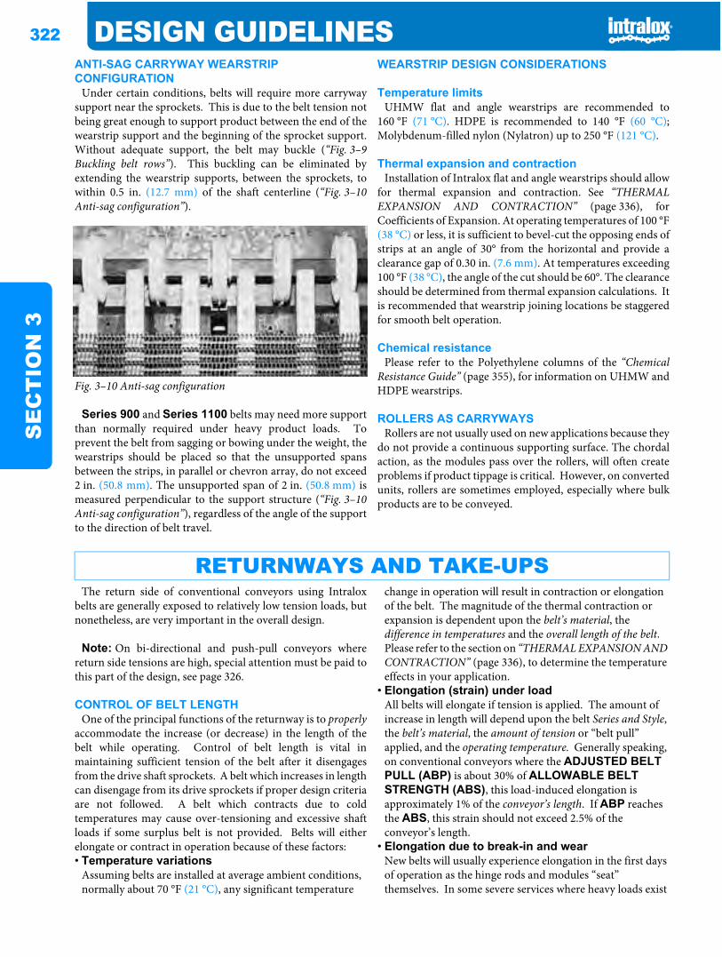
322 DESIGN GUIDELINESS
EC
TIO
N 3
ANTI-SAG CARRYWAY WEARSTRIP CONFIGURATION
Under certain conditions, belts will require more carrywaysupport near the sprockets. This is due to the belt tension notbeing great enough to support product between the end of thewearstrip support and the beginning of the sprocket support.Without adequate support, the belt may buckle (“Fig. 3–9Buckling belt rows”). This buckling can be eliminated byextending the wearstrip supports, between the sprockets, towithin 0.5 in. (12.7 mm) of the shaft centerline (“Fig. 3–10Anti-sag configuration”).
Fig. 3–10 Anti-sag configuration
Series 900 and Series 1100 belts may need more supportthan normally required under heavy product loads. Toprevent the belt from sagging or bowing under the weight, thewearstrips should be placed so that the unsupported spansbetween the strips, in parallel or chevron array, do not exceed2 in. (50.8 mm). The unsupported span of 2 in. (50.8 mm) ismeasured perpendicular to the support structure (“Fig. 3–10Anti-sag configuration”), regardless of the angle of the supportto the direction of belt travel.
WEARSTRIP DESIGN CONSIDERATIONS
Temperature limitsUHMW flat and angle wearstrips are recommended to
160 °F (71 °C). HDPE is recommended to 140 °F (60 °C);Molybdenum-filled nylon (Nylatron) up to 250 °F (121 °C).
Thermal expansion and contractionInstallation of Intralox flat and angle wearstrips should allow
for thermal expansion and contraction. See “THERMALEXPANSION AND CONTRACTION” (page 336), forCoefficients of Expansion. At operating temperatures of 100 °F(38 °C) or less, it is sufficient to bevel-cut the opposing ends ofstrips at an angle of 30° from the horizontal and provide aclearance gap of 0.30 in. (7.6 mm). At temperatures exceeding100 °F (38 °C), the angle of the cut should be 60°. The clearanceshould be determined from thermal expansion calculations. Itis recommended that wearstrip joining locations be staggeredfor smooth belt operation.
Chemical resistancePlease refer to the Polyethylene columns of the “Chemical
Resistance Guide” (page 355), for information on UHMW andHDPE wearstrips.
ROLLERS AS CARRYWAYSRollers are not usually used on new applications because they
do not provide a continuous supporting surface. The chordalaction, as the modules pass over the rollers, will often createproblems if product tippage is critical. However, on convertedunits, rollers are sometimes employed, especially where bulkproducts are to be conveyed.
The return side of conventional conveyors using Intraloxbelts are generally exposed to relatively low tension loads, butnonetheless, are very important in the overall design.
Note: On bi-directional and push-pull conveyors wherereturn side tensions are high, special attention must be paid tothis part of the design, see page 326.
CONTROL OF BELT LENGTHOne of the principal functions of the returnway is to properly
accommodate the increase (or decrease) in the length of thebelt while operating. Control of belt length is vital inmaintaining sufficient tension of the belt after it disengagesfrom the drive shaft sprockets. A belt which increases in lengthcan disengage from its drive sprockets if proper design criteriaare not followed. A belt which contracts due to coldtemperatures may cause over-tensioning and excessive shaftloads if some surplus belt is not provided. Belts will eitherelongate or contract in operation because of these factors:• Temperature variations
Assuming belts are installed at average ambient conditions, normally about 70 °F (21 °C), any significant temperature
change in operation will result in contraction or elongation of the belt. The magnitude of the thermal contraction or expansion is dependent upon the belt’s material, the difference in temperatures and the overall length of the belt. Please refer to the section on “THERMAL EXPANSION AND CONTRACTION” (page 336), to determine the temperature effects in your application.
• Elongation (strain) under loadAll belts will elongate if tension is applied. The amount of increase in length will depend upon the belt Series and Style, the belt’s material, the amount of tension or “belt pull” applied, and the operating temperature. Generally speaking, on conventional conveyors where the ADJUSTED BELT PULL (ABP) is about 30% of ALLOWABLE BELT STRENGTH (ABS), this load-induced elongation is approximately 1% of the conveyor’s length. If ABP reaches the ABS, this strain should not exceed 2.5% of the conveyor’s length.
• Elongation due to break-in and wearNew belts will usually experience elongation in the first days of operation as the hinge rods and modules “seat” themselves. In some severe services where heavy loads exist
RETURNWAYS AND TAKE-UPS
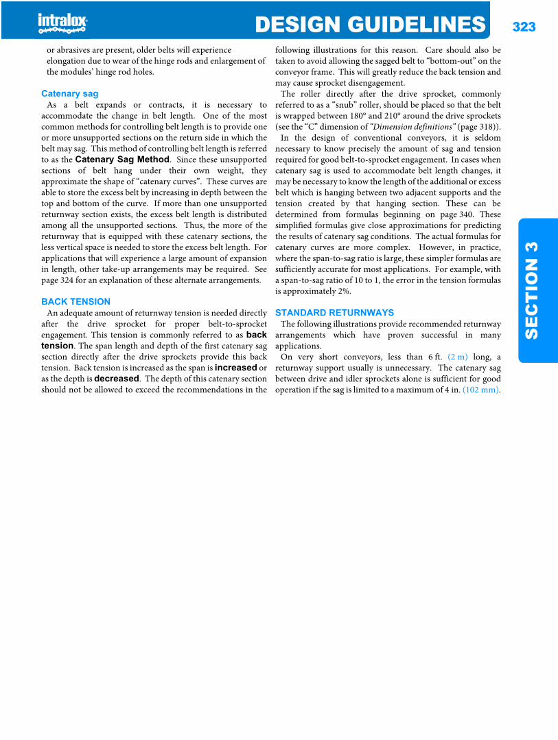
DESIGN GUIDELINES 323
SE
CT
ION
3
or abrasives are present, older belts will experience elongation due to wear of the hinge rods and enlargement of the modules’ hinge rod holes.
Catenary sagAs a belt expands or contracts, it is necessary to
accommodate the change in belt length. One of the mostcommon methods for controlling belt length is to provide oneor more unsupported sections on the return side in which thebelt may sag. This method of controlling belt length is referredto as the Catenary Sag Method. Since these unsupportedsections of belt hang under their own weight, theyapproximate the shape of “catenary curves”. These curves areable to store the excess belt by increasing in depth between thetop and bottom of the curve. If more than one unsupportedreturnway section exists, the excess belt length is distributedamong all the unsupported sections. Thus, the more of thereturnway that is equipped with these catenary sections, theless vertical space is needed to store the excess belt length. Forapplications that will experience a large amount of expansionin length, other take-up arrangements may be required. Seepage 324 for an explanation of these alternate arrangements.
BACK TENSIONAn adequate amount of returnway tension is needed directly
after the drive sprocket for proper belt-to-sprocketengagement. This tension is commonly referred to as backtension. The span length and depth of the first catenary sagsection directly after the drive sprockets provide this backtension. Back tension is increased as the span is increased oras the depth is decreased. The depth of this catenary sectionshould not be allowed to exceed the recommendations in the
following illustrations for this reason. Care should also betaken to avoid allowing the sagged belt to “bottom-out” on theconveyor frame. This will greatly reduce the back tension andmay cause sprocket disengagement.
The roller directly after the drive sprocket, commonlyreferred to as a “snub” roller, should be placed so that the beltis wrapped between 180° and 210° around the drive sprockets(see the “C” dimension of “Dimension definitions” (page 318)).
In the design of conventional conveyors, it is seldomnecessary to know precisely the amount of sag and tensionrequired for good belt-to-sprocket engagement. In cases whencatenary sag is used to accommodate belt length changes, itmay be necessary to know the length of the additional or excessbelt which is hanging between two adjacent supports and thetension created by that hanging section. These can bedetermined from formulas beginning on page 340. Thesesimplified formulas give close approximations for predictingthe results of catenary sag conditions. The actual formulas forcatenary curves are more complex. However, in practice,where the span-to-sag ratio is large, these simpler formulas aresufficiently accurate for most applications. For example, witha span-to-sag ratio of 10 to 1, the error in the tension formulasis approximately 2%.
STANDARD RETURNWAYSThe following illustrations provide recommended returnway
arrangements which have proven successful in manyapplications.
On very short conveyors, less than 6 ft. (2 m) long, areturnway support usually is unnecessary. The catenary sagbetween drive and idler sprockets alone is sufficient for goodoperation if the sag is limited to a maximum of 4 in. (102 mm).
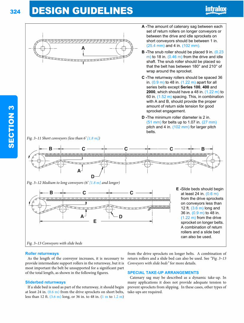
324 DESIGN GUIDELINESS
EC
TIO
N 3
Roller returnwaysAs the length of the conveyor increases, it is necessary to
provide intermediate support rollers in the returnway, but it ismost important the belt be unsupported for a significant partof the total length, as shown in the following figures.
Sliderbed returnwaysIf a slide bed is used as part of the returnway, it should begin
at least 24 in. (0.6 m) from the drive sprockets on short belts,less than 12 ft. (3.6 m) long, or 36 in. to 48 in. (1 m to 1.2 m)
from the drive sprockets on longer belts. A combination ofreturn rollers and a slide bed can also be used. See “Fig. 3–13Conveyors with slide beds” for more details.
SPECIAL TAKE-UP ARRANGEMENTSCatenary sag may be described as a dynamic take-up. In
many applications it does not provide adequate tension toprevent sprockets from slipping. In these cases, other types oftake-ups are required.
A -The amount of catenary sag between each set of return rollers on longer conveyors or between the drive and idle sprockets on short conveyors should be between 1 in. (25.4 mm) and 4 in. (102 mm).
B -The snub roller should be placed 9 in. (0.23 m) to 18 in. (0.46 m) from the drive and idle shaft. The snub roller should be placed so that the belt has between 180° and 210° of wrap around the sprocket.
C -The returnway rollers should be spaced 36 in. (0.9 m) to 48 in. (1.22 m) apart for all series belts except Series 100, 400 and 2000, which should have a 48 in. (1.22 m) to 60 in. (1.52 m) spacing. This, in combination with A and B, should provide the proper amount of return side tension for good sprocket engagement.
D -The minimum roller diameter is 2 in. (51 mm) for belts up to 1.07 in. (27 mm)pitch and 4 in. (102 mm) for larger pitch belts.
Fig. 3–11 Short conveyors (less than 6’ [1.8 m])
Fig. 3–12 Medium to long conveyors (6’ [1.8 m] and longer)E -Slide beds should begin
at least 24 in. (0.6 m)from the drive sprockets on conveyors less than 12 ft. (3.6 m) long and 36 in. (0.9 m) to 48 in. (1.22 m) from the drive sprocket on longer belts. A combination of return rollers and a slide bed can also be used.
Fig. 3–13 Conveyors with slide beds
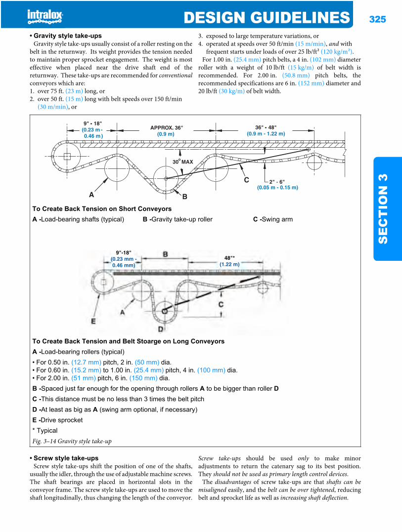
DESIGN GUIDELINES 325
SE
CT
ION
3
• Gravity style take-upsGravity style take-ups usually consist of a roller resting on the
belt in the returnway. Its weight provides the tension neededto maintain proper sprocket engagement. The weight is mosteffective when placed near the drive shaft end of thereturnway. These take-ups are recommended for conventionalconveyors which are:1. over 75 ft. (23 m) long, or2. over 50 ft. (15 m) long with belt speeds over 150 ft/min
(30 m/min), or
3. exposed to large temperature variations, or4. operated at speeds over 50 ft/min (15 m/min), and with
frequent starts under loads of over 25 lb/ft2 (120 kg/m2).For 1.00 in. (25.4 mm) pitch belts, a 4 in. (102 mm) diameter
roller with a weight of 10 lb/ft (15 kg/m) of belt width isrecommended. For 2.00 in. (50.8 mm) pitch belts, therecommended specifications are 6 in. (152 mm) diameter and20 lb/ft (30 kg/m) of belt width.
• Screw style take-upsScrew style take-ups shift the position of one of the shafts,
usually the idler, through the use of adjustable machine screws.The shaft bearings are placed in horizontal slots in theconveyor frame. The screw style take-ups are used to move theshaft longitudinally, thus changing the length of the conveyor.
Screw take-ups should be used only to make minoradjustments to return the catenary sag to its best position.They should not be used as primary length control devices.
The disadvantages of screw take-ups are that shafts can bemisaligned easily, and the belt can be over tightened, reducingbelt and sprocket life as well as increasing shaft deflection.
To Create Back Tension on Short ConveyorsA -Load-bearing shafts (typical) B -Gravity take-up roller C -Swing arm
To Create Back Tension and Belt Stoarge on Long ConveyorsA -Load-bearing rollers (typical)• For 0.50 in. (12.7 mm) pitch, 2 in. (50 mm) dia.• For 0.60 in. (15.2 mm) to 1.00 in. (25.4 mm) pitch, 4 in. (100 mm) dia.• For 2.00 in. (51 mm) pitch, 6 in. (150 mm) dia.B -Spaced just far enough for the opening through rollers A to be bigger than roller DC -This distance must be no less than 3 times the belt pitchD -At least as big as A (swing arm optional, if necessary)E -Drive sprocket* TypicalFig. 3–14 Gravity style take-up
(0.05 m - 0.15 m)
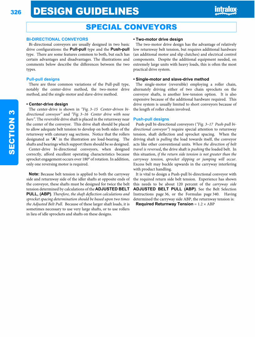
326 DESIGN GUIDELINESS
EC
TIO
N 3
BI-DIRECTIONAL CONVEYORSBi-directional conveyors are usually designed in two basic
drive configurations: the Pull-pull type and the Push-pulltype. There are some features common to both, but each hascertain advantages and disadvantages. The illustrations andcomments below describe the differences between the twotypes.
Pull-pull designsThere are three common variations of the Pull-pull type,
notably the center-drive method, the two-motor drivemethod, and the single-motor and slave-drive method.
• Center-drive designThe center-drive is shown in “Fig. 3–15 Center-driven bi-
directional conveyor” and “Fig. 3–16 Center drive with nosebars”. The reversible drive shaft is placed in the returnway nearthe center of the conveyor. This drive shaft should be placedto allow adequate belt tension to develop on both sides of thereturnway with catenary sag sections. Notice that the rollersdesignated as “A” in the illustration are load-bearing. Theshafts and bearings which support them should be so designed.
Center-drive bi-directional conveyors, when designedcorrectly, afford excellent operating characteristics becausesprocket engagement occurs over 180° of rotation. In addition,only one reversing motor is required.
Note: Because belt tension is applied to both the carrywayside and returnway side of the idler shafts at opposite ends ofthe conveyor, these shafts must be designed for twice the belttension determined by calculations of the ADJUSTED BELTPULL, (ABP). Therefore, the shaft deflection calculations andsprocket spacing determination should be based upon two timesthe Adjusted Belt Pull. Because of these larger shaft loads, it issometimes necessary to use very large shafts, or to use rollersin lieu of idle sprockets and shafts on these designs.
• Two-motor drive designThe two-motor drive design has the advantage of relatively
low returnway belt tension, but requires additional hardware(an additional motor and slip clutches) and electrical controlcomponents. Despite the additional equipment needed, onextremely large units with heavy loads, this is often the mostpractical drive system.
• Single-motor and slave-drive methodThe single-motor (reversible) employing a roller chain,
alternately driving either of two chain sprockets on theconveyor shafts, is another low-tension option. It is alsoexpensive because of the additional hardware required. Thisdrive system is usually limited to short conveyors because ofthe length of roller chain involved.
Push-pull designsPush-pull bi-directional conveyors (“Fig. 3–17 Push-pull bi-
directional conveyor”) require special attention to returnwaytension, shaft deflection and sprocket spacing. When thedriving shaft is pulling the load towards itself, the conveyoracts like other conventional units. When the direction of belttravel is reversed, the drive shaft is pushing the loaded belt. Inthis situation, if the return side tension is not greater than thecarryway tension, sprocket slipping or jumping will occur.Excess belt may buckle upwards in the carryway interferingwith product handling.
It is vital to design a Push-pull bi-directional conveyor withthe required return side belt tension. Experience has shownthis needs to be about 120 percent of the carryway sideADJUSTED BELT PULL (ABP). See the Belt SelectionInstructions page 36, or the Formulas page 340. Havingdetermined the carryway side ABP, the returnway tension is:
Required Returnway Tension = 1.2 × ABP
SPECIAL CONVEYORS
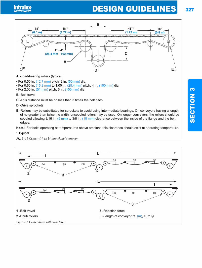
DESIGN GUIDELINES 327
SE
CT
ION
3
A -Load-bearing rollers (typical):• For 0.50 in. (12.7 mm) pitch, 2 in. (50 mm) dia.• For 0.60 in. (15.2 mm) to 1.00 in. (25.4 mm) pitch, 4 in. (100 mm) dia.• For 2.00 in. (51 mm) pitch, 6 in. (150 mm) dia.B -Belt travelC -This distance must be no less than 3 times the belt pitchD -Drive sprocketsE -Rollers may be substituted for sprockets to avoid using intermediate bearings. On conveyors having a length
of no greater than twice the width, unspooled rollers may be used. On longer conveyors, the rollers should be spooled allowing 3/16 in. (5 mm) to 3/8 in. (10 mm) clearance between the inside of the flange and the belt edges.
Note: For belts operating at temperatures above ambient, this clearance should exist at operating temperature.* TypicalFig. 3–15 Center-driven bi-directional conveyor
1 -Belt travel 3 -Reaction force2 -Snub rollers L -Length of conveyor, ft. (m), CL to CLFig. 3–16 Center drive with nose bars
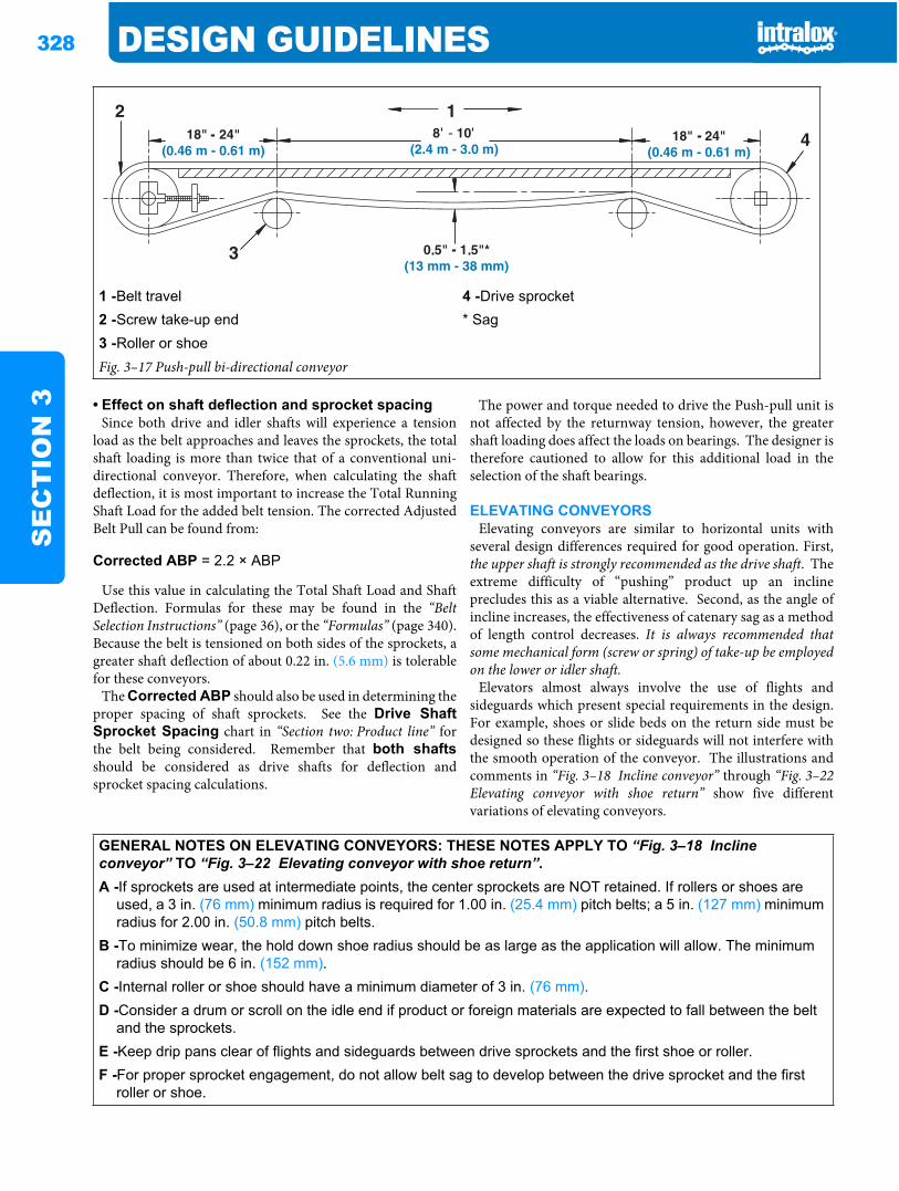
328 DESIGN GUIDELINESS
EC
TIO
N 3 • Effect on shaft deflection and sprocket spacing
Since both drive and idler shafts will experience a tensionload as the belt approaches and leaves the sprockets, the totalshaft loading is more than twice that of a conventional uni-directional conveyor. Therefore, when calculating the shaftdeflection, it is most important to increase the Total RunningShaft Load for the added belt tension. The corrected AdjustedBelt Pull can be found from:
Use this value in calculating the Total Shaft Load and ShaftDeflection. Formulas for these may be found in the “BeltSelection Instructions” (page 36), or the “Formulas” (page 340).Because the belt is tensioned on both sides of the sprockets, agreater shaft deflection of about 0.22 in. (5.6 mm) is tolerablefor these conveyors.
The Corrected ABP should also be used in determining theproper spacing of shaft sprockets. See the Drive ShaftSprocket Spacing chart in “Section two: Product line” forthe belt being considered. Remember that both shaftsshould be considered as drive shafts for deflection andsprocket spacing calculations.
The power and torque needed to drive the Push-pull unit isnot affected by the returnway tension, however, the greatershaft loading does affect the loads on bearings. The designer istherefore cautioned to allow for this additional load in theselection of the shaft bearings.
ELEVATING CONVEYORSElevating conveyors are similar to horizontal units with
several design differences required for good operation. First,the upper shaft is strongly recommended as the drive shaft. Theextreme difficulty of “pushing” product up an inclineprecludes this as a viable alternative. Second, as the angle ofincline increases, the effectiveness of catenary sag as a methodof length control decreases. It is always recommended thatsome mechanical form (screw or spring) of take-up be employedon the lower or idler shaft.
Elevators almost always involve the use of flights andsideguards which present special requirements in the design.For example, shoes or slide beds on the return side must bedesigned so these flights or sideguards will not interfere withthe smooth operation of the conveyor. The illustrations andcomments in “Fig. 3–18 Incline conveyor” through “Fig. 3–22Elevating conveyor with shoe return” show five differentvariations of elevating conveyors.
1 -Belt travel 4 -Drive sprocket2 -Screw take-up end * Sag3 -Roller or shoeFig. 3–17 Push-pull bi-directional conveyor
Corrected ABP = 2.2 × ABP
GENERAL NOTES ON ELEVATING CONVEYORS: THESE NOTES APPLY TO “Fig. 3–18 Incline conveyor” TO “Fig. 3–22 Elevating conveyor with shoe return”.A -If sprockets are used at intermediate points, the center sprockets are NOT retained. If rollers or shoes are
used, a 3 in. (76 mm) minimum radius is required for 1.00 in. (25.4 mm) pitch belts; a 5 in. (127 mm) minimum radius for 2.00 in. (50.8 mm) pitch belts.
B -To minimize wear, the hold down shoe radius should be as large as the application will allow. The minimum radius should be 6 in. (152 mm).
C -Internal roller or shoe should have a minimum diameter of 3 in. (76 mm).D -Consider a drum or scroll on the idle end if product or foreign materials are expected to fall between the belt
and the sprockets.E -Keep drip pans clear of flights and sideguards between drive sprockets and the first shoe or roller.F -For proper sprocket engagement, do not allow belt sag to develop between the drive sprocket and the first
roller or shoe.
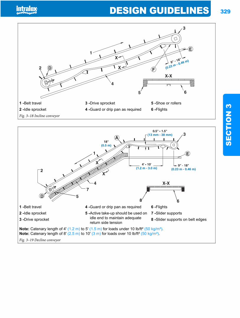
DESIGN GUIDELINES 329
SE
CT
ION
3
1 -Belt travel 3 -Drive sprocket 5 -Shoe or rollers2 -Idle sprocket 4 -Guard or drip pan as required 6 -FlightsFig. 3–18 Incline conveyor
1 -Belt travel 4 -Guard or drip pan as required 6 -Flights2 -Idle sprocket 5 -Active take-up should be used on
idle end to maintain adequate return side tension
7 -Slider supports3 -Drive sprocket 8 -Slider supports on belt edges
Note: Catenary length of 4' (1.2 m) to 5' (1.5 m) for loads under 10 lb/ft² (50 kg/m²).Note: Catenary length of 8' (2.5 m) to 10' (3 m) for loads over 10 lb/ft² (50 kg/m²).Fig. 3–19 Decline conveyor
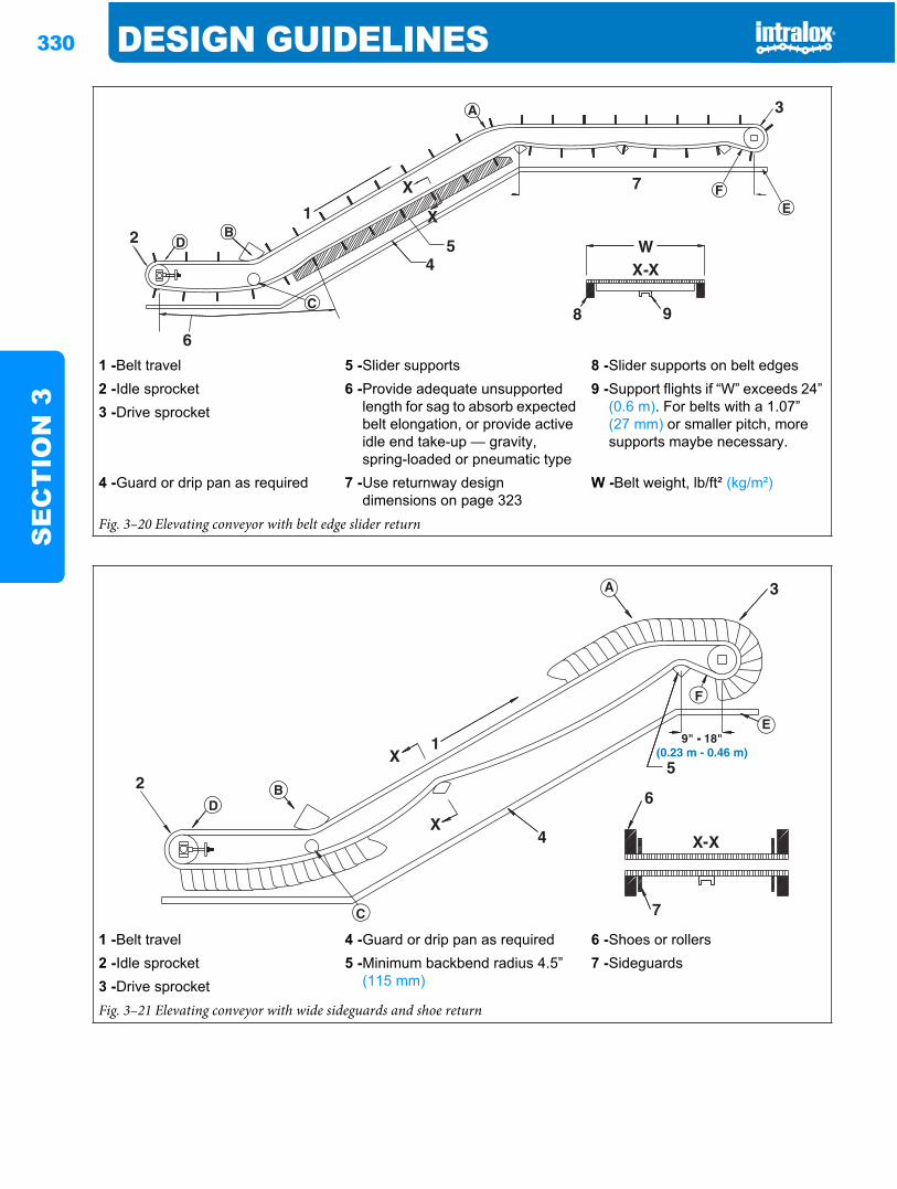
330 DESIGN GUIDELINESS
EC
TIO
N 3
1 -Belt travel 5 -Slider supports 8 -Slider supports on belt edges2 -Idle sprocket 6 -Provide adequate unsupported
length for sag to absorb expected belt elongation, or provide active idle end take-up — gravity, spring-loaded or pneumatic type
9 -Support flights if “W” exceeds 24” (0.6 m). For belts with a 1.07” (27 mm) or smaller pitch, more supports maybe necessary.
3 -Drive sprocket
4 -Guard or drip pan as required 7 -Use returnway design dimensions on page 323
W -Belt weight, lb/ft² (kg/m²)
Fig. 3–20 Elevating conveyor with belt edge slider return
1 -Belt travel 4 -Guard or drip pan as required 6 -Shoes or rollers2 -Idle sprocket 5 -Minimum backbend radius 4.5”
(115 mm)7 -Sideguards
3 -Drive sprocketFig. 3–21 Elevating conveyor with wide sideguards and shoe return
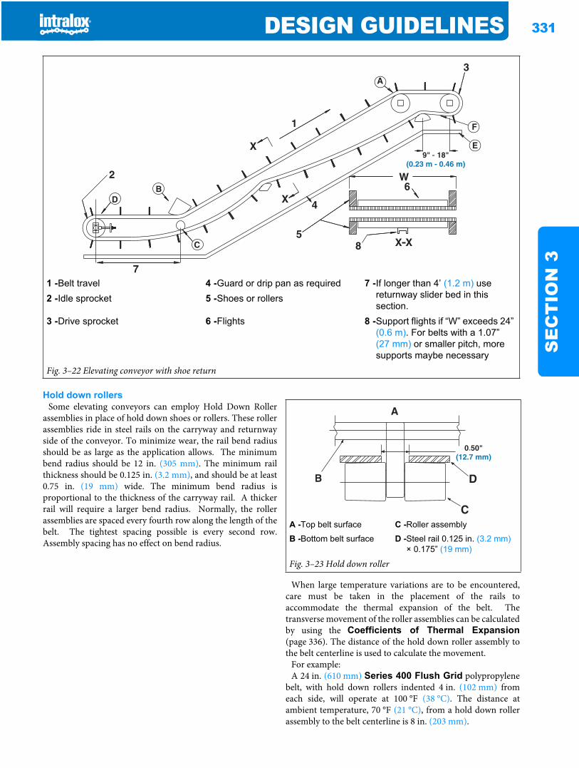
DESIGN GUIDELINES 331
SE
CT
ION
3
Hold down rollersSome elevating conveyors can employ Hold Down Roller
assemblies in place of hold down shoes or rollers. These rollerassemblies ride in steel rails on the carryway and returnwayside of the conveyor. To minimize wear, the rail bend radiusshould be as large as the application allows. The minimumbend radius should be 12 in. (305 mm). The minimum railthickness should be 0.125 in. (3.2 mm), and should be at least0.75 in. (19 mm) wide. The minimum bend radius isproportional to the thickness of the carryway rail. A thickerrail will require a larger bend radius. Normally, the rollerassemblies are spaced every fourth row along the length of thebelt. The tightest spacing possible is every second row.Assembly spacing has no effect on bend radius.
When large temperature variations are to be encountered,care must be taken in the placement of the rails toaccommodate the thermal expansion of the belt. Thetransverse movement of the roller assemblies can be calculatedby using the Coefficients of Thermal Expansion(page 336). The distance of the hold down roller assembly tothe belt centerline is used to calculate the movement.
For example:A 24 in. (610 mm) Series 400 Flush Grid polypropylene
belt, with hold down rollers indented 4 in. (102 mm) fromeach side, will operate at 100 °F (38 °C). The distance atambient temperature, 70 °F (21 °C), from a hold down rollerassembly to the belt centerline is 8 in. (203 mm).
1 -Belt travel 4 -Guard or drip pan as required 7 -If longer than 4’ (1.2 m) use returnway slider bed in this section.
2 -Idle sprocket 5 -Shoes or rollers
3 -Drive sprocket 6 -Flights 8 -Support flights if “W” exceeds 24” (0.6 m). For belts with a 1.07” (27 mm) or smaller pitch, more supports maybe necessary
Fig. 3–22 Elevating conveyor with shoe return
A -Top belt surface C -Roller assembly
B -Bottom belt surface D -Steel rail 0.125 in. (3.2 mm)× 0.175” (19 mm)
Fig. 3–23 Hold down roller
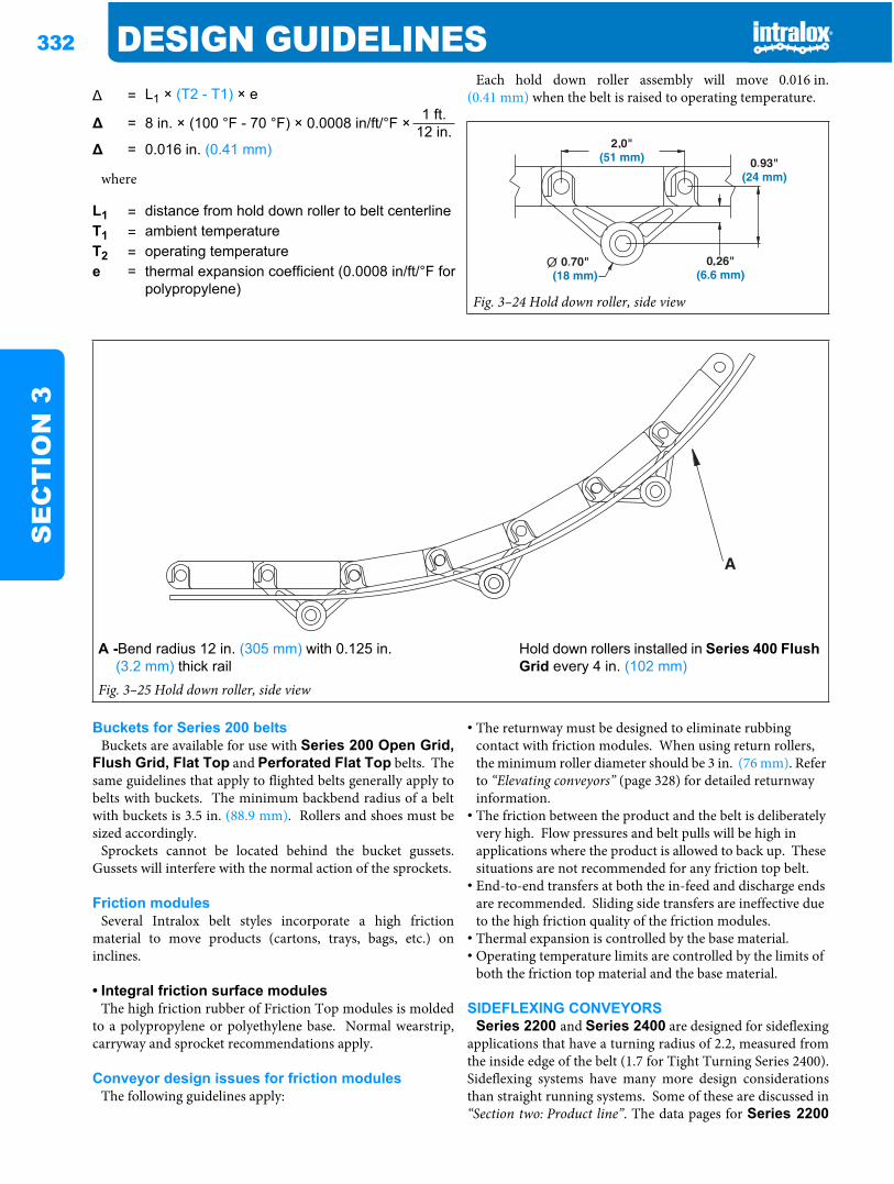
332 DESIGN GUIDELINESS
EC
TIO
N 3
where
Each hold down roller assembly will move 0.016 in.(0.41 mm) when the belt is raised to operating temperature.
Buckets for Series 200 beltsBuckets are available for use with Series 200 Open Grid,
Flush Grid, Flat Top and Perforated Flat Top belts. Thesame guidelines that apply to flighted belts generally apply tobelts with buckets. The minimum backbend radius of a beltwith buckets is 3.5 in. (88.9 mm). Rollers and shoes must besized accordingly.
Sprockets cannot be located behind the bucket gussets.Gussets will interfere with the normal action of the sprockets.
Friction modulesSeveral Intralox belt styles incorporate a high friction
material to move products (cartons, trays, bags, etc.) oninclines.
• Integral friction surface modulesThe high friction rubber of Friction Top modules is molded
to a polypropylene or polyethylene base. Normal wearstrip,carryway and sprocket recommendations apply.
Conveyor design issues for friction modulesThe following guidelines apply:
• The returnway must be designed to eliminate rubbing contact with friction modules. When using return rollers, the minimum roller diameter should be 3 in. (76 mm). Refer to “Elevating conveyors” (page 328) for detailed returnway information.
• The friction between the product and the belt is deliberately very high. Flow pressures and belt pulls will be high in applications where the product is allowed to back up. These situations are not recommended for any friction top belt.
• End-to-end transfers at both the in-feed and discharge ends are recommended. Sliding side transfers are ineffective due to the high friction quality of the friction modules.
• Thermal expansion is controlled by the base material.• Operating temperature limits are controlled by the limits of
both the friction top material and the base material.
SIDEFLEXING CONVEYORSSeries 2200 and Series 2400 are designed for sideflexing
applications that have a turning radius of 2.2, measured fromthe inside edge of the belt (1.7 for Tight Turning Series 2400).Sideflexing systems have many more design considerationsthan straight running systems. Some of these are discussed in“Section two: Product line”. The data pages for Series 2200
= L1 × (T2 - T1) × e
= 8 in. × (100 °F - 70 °F) × 0.0008 in/ft/°F × 1 ft.12 in.
= 0.016 in. (0.41 mm)
L1 = distance from hold down roller to belt centerlineT1 = ambient temperatureT2 = operating temperaturee = thermal expansion coefficient (0.0008 in/ft/°F for
polypropylene)Fig. 3–24 Hold down roller, side view
A -Bend radius 12 in. (305 mm) with 0.125 in. (3.2 mm) thick rail
Hold down rollers installed in Series 400 Flush Grid every 4 in. (102 mm)
Fig. 3–25 Hold down roller, side view
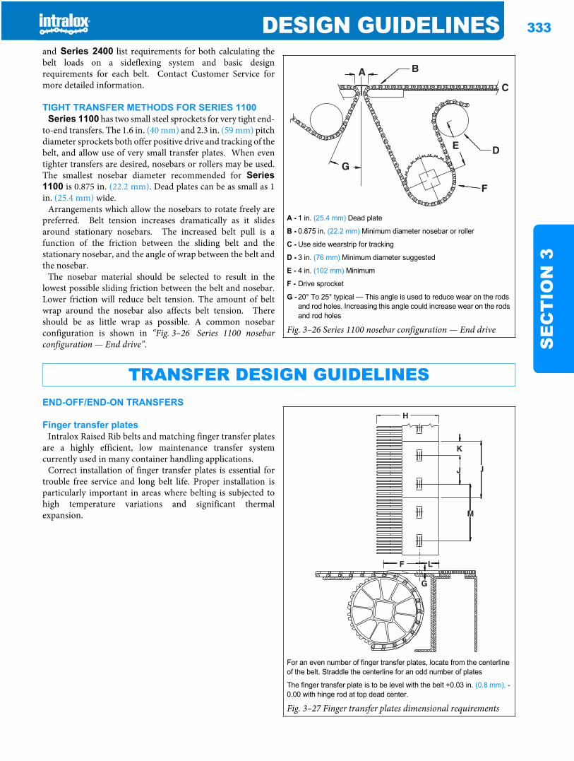
DESIGN GUIDELINES 333
SE
CT
ION
3
and Series 2400 list requirements for both calculating thebelt loads on a sideflexing system and basic designrequirements for each belt. Contact Customer Service formore detailed information.
TIGHT TRANSFER METHODS FOR SERIES 1100Series 1100 has two small steel sprockets for very tight end-
to-end transfers. The 1.6 in. (40 mm) and 2.3 in. (59 mm) pitchdiameter sprockets both offer positive drive and tracking of thebelt, and allow use of very small transfer plates. When eventighter transfers are desired, nosebars or rollers may be used.The smallest nosebar diameter recommended for Series1100 is 0.875 in. (22.2 mm). Dead plates can be as small as 1in. (25.4 mm) wide.
Arrangements which allow the nosebars to rotate freely arepreferred. Belt tension increases dramatically as it slidesaround stationary nosebars. The increased belt pull is afunction of the friction between the sliding belt and thestationary nosebar, and the angle of wrap between the belt andthe nosebar.
The nosebar material should be selected to result in thelowest possible sliding friction between the belt and nosebar.Lower friction will reduce belt tension. The amount of beltwrap around the nosebar also affects belt tension. Thereshould be as little wrap as possible. A common nosebarconfiguration is shown in “Fig. 3–26 Series 1100 nosebarconfiguration — End drive”.
END-OFF/END-ON TRANSFERS
Finger transfer platesIntralox Raised Rib belts and matching finger transfer plates
are a highly efficient, low maintenance transfer systemcurrently used in many container handling applications.
Correct installation of finger transfer plates is essential fortrouble free service and long belt life. Proper installation isparticularly important in areas where belting is subjected tohigh temperature variations and significant thermalexpansion.
A - 1 in. (25.4 mm) Dead plate
B - 0.875 in. (22.2 mm) Minimum diameter nosebar or roller
C - Use side wearstrip for tracking
D - 3 in. (76 mm) Minimum diameter suggested
E - 4 in. (102 mm) Minimum
F - Drive sprocket
G - 20° To 25° typical — This angle is used to reduce wear on the rods and rod holes. Increasing this angle could increase wear on the rods and rod holes
Fig. 3–26 Series 1100 nosebar configuration — End drive
TRANSFER DESIGN GUIDELINES
For an even number of finger transfer plates, locate from the centerline of the belt. Straddle the centerline for an odd number of plates
The finger transfer plate is to be level with the belt +0.03 in. (0.8 mm), -0.00 with hinge rod at top dead center.
Fig. 3–27 Finger transfer plates dimensional requirements
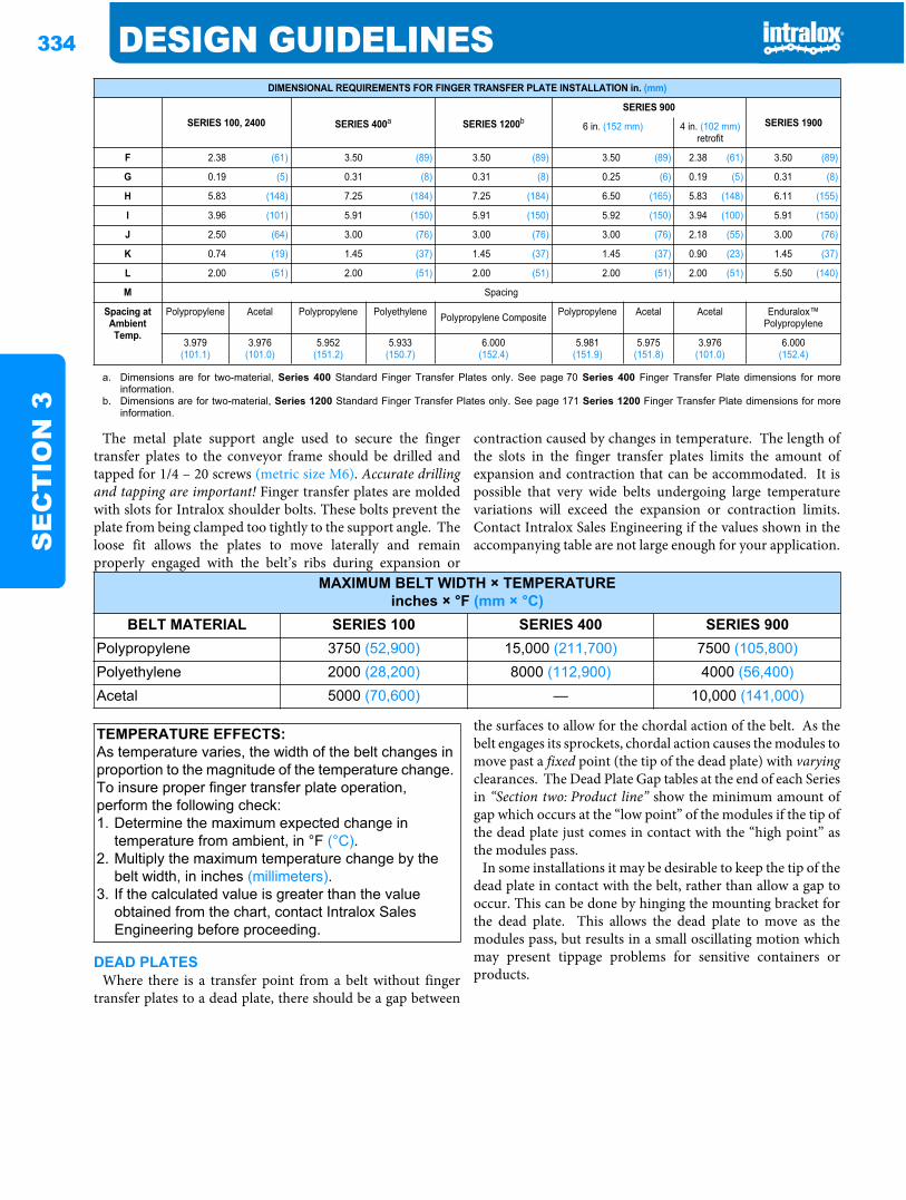
334 DESIGN GUIDELINESS
EC
TIO
N 3
The metal plate support angle used to secure the fingertransfer plates to the conveyor frame should be drilled andtapped for 1/4 – 20 screws (metric size M6). Accurate drillingand tapping are important! Finger transfer plates are moldedwith slots for Intralox shoulder bolts. These bolts prevent theplate from being clamped too tightly to the support angle. Theloose fit allows the plates to move laterally and remainproperly engaged with the belt’s ribs during expansion or
contraction caused by changes in temperature. The length ofthe slots in the finger transfer plates limits the amount ofexpansion and contraction that can be accommodated. It ispossible that very wide belts undergoing large temperaturevariations will exceed the expansion or contraction limits.Contact Intralox Sales Engineering if the values shown in theaccompanying table are not large enough for your application.
DEAD PLATESWhere there is a transfer point from a belt without finger
transfer plates to a dead plate, there should be a gap between
the surfaces to allow for the chordal action of the belt. As thebelt engages its sprockets, chordal action causes the modules tomove past a fixed point (the tip of the dead plate) with varyingclearances. The Dead Plate Gap tables at the end of each Seriesin “Section two: Product line” show the minimum amount ofgap which occurs at the “low point” of the modules if the tip ofthe dead plate just comes in contact with the “high point” asthe modules pass.
In some installations it may be desirable to keep the tip of thedead plate in contact with the belt, rather than allow a gap tooccur. This can be done by hinging the mounting bracket forthe dead plate. This allows the dead plate to move as themodules pass, but results in a small oscillating motion whichmay present tippage problems for sensitive containers orproducts.
DIMENSIONAL REQUIREMENTS FOR FINGER TRANSFER PLATE INSTALLATION in. (mm)
SERIES 100, 2400 SERIES 400a SERIES 1200bSERIES 900
SERIES 19006 in. (152 mm) 4 in. (102 mm) retrofit
F 2.38 (61) 3.50 (89) 3.50 (89) 3.50 (89) 2.38 (61) 3.50 (89)
G 0.19 (5) 0.31 (8) 0.31 (8) 0.25 (6) 0.19 (5) 0.31 (8)
H 5.83 (148) 7.25 (184) 7.25 (184) 6.50 (165) 5.83 (148) 6.11 (155)
I 3.96 (101) 5.91 (150) 5.91 (150) 5.92 (150) 3.94 (100) 5.91 (150)
J 2.50 (64) 3.00 (76) 3.00 (76) 3.00 (76) 2.18 (55) 3.00 (76)
K 0.74 (19) 1.45 (37) 1.45 (37) 1.45 (37) 0.90 (23) 1.45 (37)
L 2.00 (51) 2.00 (51) 2.00 (51) 2.00 (51) 2.00 (51) 5.50 (140)
M Spacing
Spacing at Ambient Temp.
Polypropylene Acetal Polypropylene Polyethylene Polypropylene Composite Polypropylene Acetal Acetal Enduralox™ Polypropylene
3.979(101.1)
3.976(101.0)
5.952(151.2)
5.933(150.7)
6.000(152.4)
5.981(151.9)
5.975(151.8)
3.976(101.0)
6.000(152.4)
a. Dimensions are for two-material, Series 400 Standard Finger Transfer Plates only. See page 70 Series 400 Finger Transfer Plate dimensions for moreinformation.
b. Dimensions are for two-material, Series 1200 Standard Finger Transfer Plates only. See page 171 Series 1200 Finger Transfer Plate dimensions for moreinformation.
MAXIMUM BELT WIDTH × TEMPERATUREinches × °F (mm × °C)
BELT MATERIAL SERIES 100 SERIES 400 SERIES 900Polypropylene 3750 (52,900) 15,000 (211,700) 7500 (105,800)Polyethylene 2000 (28,200) 8000 (112,900) 4000 (56,400)Acetal 5000 (70,600) — 10,000 (141,000)
TEMPERATURE EFFECTS:As temperature varies, the width of the belt changes in proportion to the magnitude of the temperature change. To insure proper finger transfer plate operation, perform the following check:1. Determine the maximum expected change in
temperature from ambient, in °F (°C).2. Multiply the maximum temperature change by the
belt width, in inches (millimeters).3. If the calculated value is greater than the value
obtained from the chart, contact Intralox Sales Engineering before proceeding.
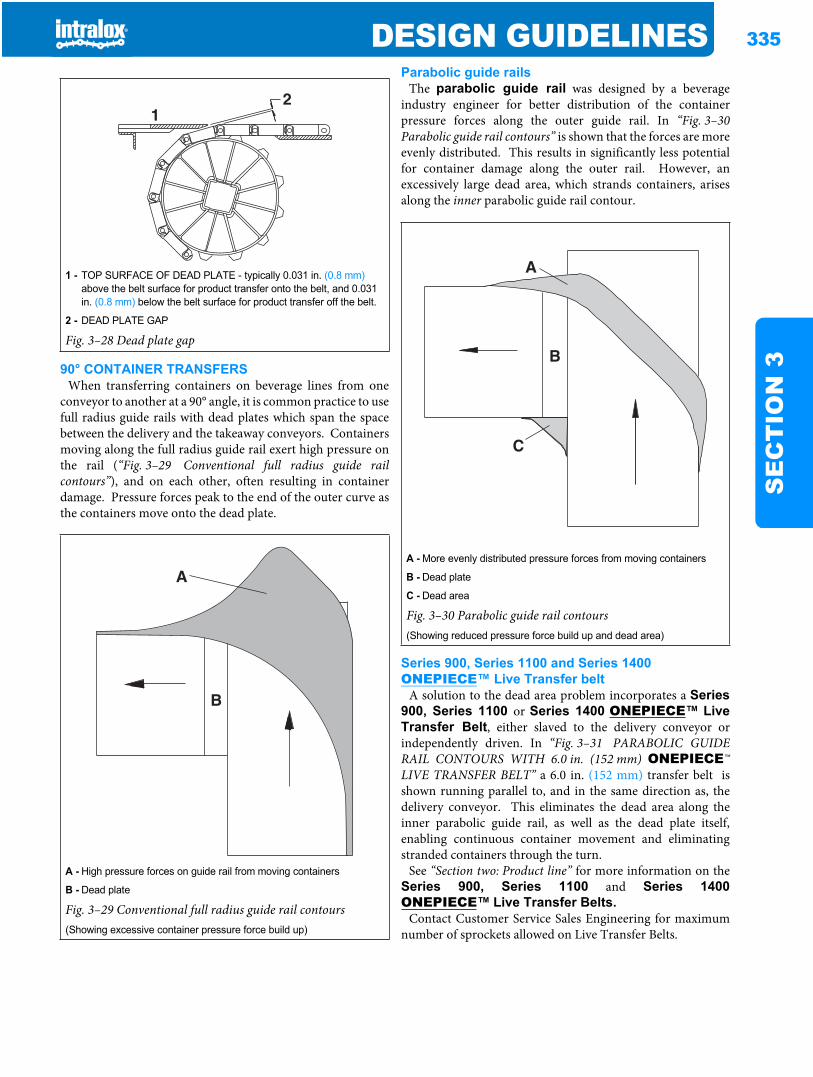
DESIGN GUIDELINES 335
SE
CT
ION
390° CONTAINER TRANSFERSWhen transferring containers on beverage lines from one
conveyor to another at a 90° angle, it is common practice to usefull radius guide rails with dead plates which span the spacebetween the delivery and the takeaway conveyors. Containersmoving along the full radius guide rail exert high pressure onthe rail (“Fig. 3–29 Conventional full radius guide railcontours”), and on each other, often resulting in containerdamage. Pressure forces peak to the end of the outer curve asthe containers move onto the dead plate.
Parabolic guide railsThe parabolic guide rail was designed by a beverage
industry engineer for better distribution of the containerpressure forces along the outer guide rail. In “Fig. 3–30Parabolic guide rail contours” is shown that the forces are moreevenly distributed. This results in significantly less potentialfor container damage along the outer rail. However, anexcessively large dead area, which strands containers, arisesalong the inner parabolic guide rail contour.
Series 900, Series 1100 and Series 1400 ONEPIECE™ Live Transfer belt
A solution to the dead area problem incorporates a Series900, Series 1100 or Series 1400 ONEPIECE™ LiveTransfer Belt, either slaved to the delivery conveyor orindependently driven. In “Fig. 3–31 PARABOLIC GUIDERAIL CONTOURS WITH 6.0 in. (152 mm) ONEPIECE™LIVE TRANSFER BELT” a 6.0 in. (152 mm) transfer belt isshown running parallel to, and in the same direction as, thedelivery conveyor. This eliminates the dead area along theinner parabolic guide rail, as well as the dead plate itself,enabling continuous container movement and eliminatingstranded containers through the turn.
See “Section two: Product line” for more information on theSeries 900, Series 1100 and Series 1400ONEPIECE™ Live Transfer Belts.
Contact Customer Service Sales Engineering for maximumnumber of sprockets allowed on Live Transfer Belts.
1 - TOP SURFACE OF DEAD PLATE - typically 0.031 in. (0.8 mm)above the belt surface for product transfer onto the belt, and 0.031 in. (0.8 mm) below the belt surface for product transfer off the belt.
2 - DEAD PLATE GAP
Fig. 3–28 Dead plate gap
A - High pressure forces on guide rail from moving containers
B - Dead plate
Fig. 3–29 Conventional full radius guide rail contours(Showing excessive container pressure force build up)
21
A - More evenly distributed pressure forces from moving containers
B - Dead plate
C - Dead area
Fig. 3–30 Parabolic guide rail contours(Showing reduced pressure force build up and dead area)
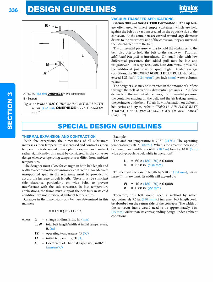
336 DESIGN GUIDELINESS
EC
TIO
N 3
VACUUM TRANSFER APPLICATIONSSeries 900 and Series 1100 Perforated Flat Top belts
are often used to invert empty containers which are heldagainst the belt by a vacuum created on the opposite side of theconveyor. As the containers are carried around large diameterdrums to the returnway side of the conveyor, they are inverted,then discharged from the belt.
The differential pressure acting to hold the containers to thebelt, also acts to hold the belt to the carryway. Thus, anadditional belt pull is introduced. On small belts with lowdifferential pressures, this added pull may be low andinsignificant. On large belts with high differential pressures,the additional pull may be quite high. Under averageconditions, the SPECIFIC ADDED BELT PULL should notexceed 1.25 lb/ft2 (0.24 kg/m2) per inch (mm) water column,vacuum.
The designer also may be interested in the amount of air flowthrough the belt at various differential pressures. Air flowdepends on the amount of open area, the differential pressure,the container spacing on the belt, and the air leakage aroundthe perimeter of the belt. For air flow information on differentbelt series and styles, refer to “Table 11 AIR FLOW RATETHROUGH BELT, PER SQUARE FOOT OF BELT AREA”(page 352) .
THERMAL EXPANSION AND CONTRACTIONWith few exceptions, the dimensions of all substances
increase as their temperature is increased and contract as theirtemperature is decreased. Since plastics expand and contractrather significantly, this must be considered in the conveyordesign whenever operating temperatures differ from ambienttemperature.
The designer must allow for changes in both belt length andwidth to accommodate expansion or contraction. An adequateunsupported span in the returnway must be provided toabsorb the increase in belt length. There must be sufficientside clearance, particularly on wide belts, to preventinterference with the side structure. In low temperatureapplications, the frame must support the belt fully in its coldcondition, yet not interfere at ambient temperatures.
Changes in the dimensions of a belt are determined in thismanner:
Example:The ambient temperature is 70 °F (21 °C). The operating
temperature is 180 °F (82 °C). What is the greatest increase inbelt length and width of a 60 ft. (18.3 m) long by 10 ft. (3 m)wide polypropylene belt while in operation?
This belt will increase in length by 5.28 in. (134 mm), not aninsignificant amount. Its width will expand by:
Therefore, this belt would need a method by whichapproximately 5.5 in. (140 mm) of increased belt length couldbe absorbed on the return side of the conveyor. The width ofthe conveyor frame would need to be approximately 1 in.(25 mm) wider than its corresponding design under ambientconditions.
A - 6.0 in. (152 mm) ONEPIECE™ live transfer belt
B - Support
Fig. 3–31 PARABOLIC GUIDE RAIL CONTOURS WITH 6.0 in. (152 mm) ONEPIECE™ LIVE TRANSFER BELT
SPECIAL DESIGN GUIDELINES
= L1 × (T2 -T1) × e
where: Δ = change in dimension, in. (mm)L, W= total belt length/width at initial temperature,
ft. (m)T2 = operating temperature, °F (°C)T1 = initial temperature, °F (°C)e = Coefficient of Thermal Expansion, in/ft/°F
(mm/m/°C)
L = 60 × (180 - 70) × 0.0008= 5.28 in. (134 mm)
W = 10 × (180 - 70) × 0.0008= 0.88 in. (22 mm)
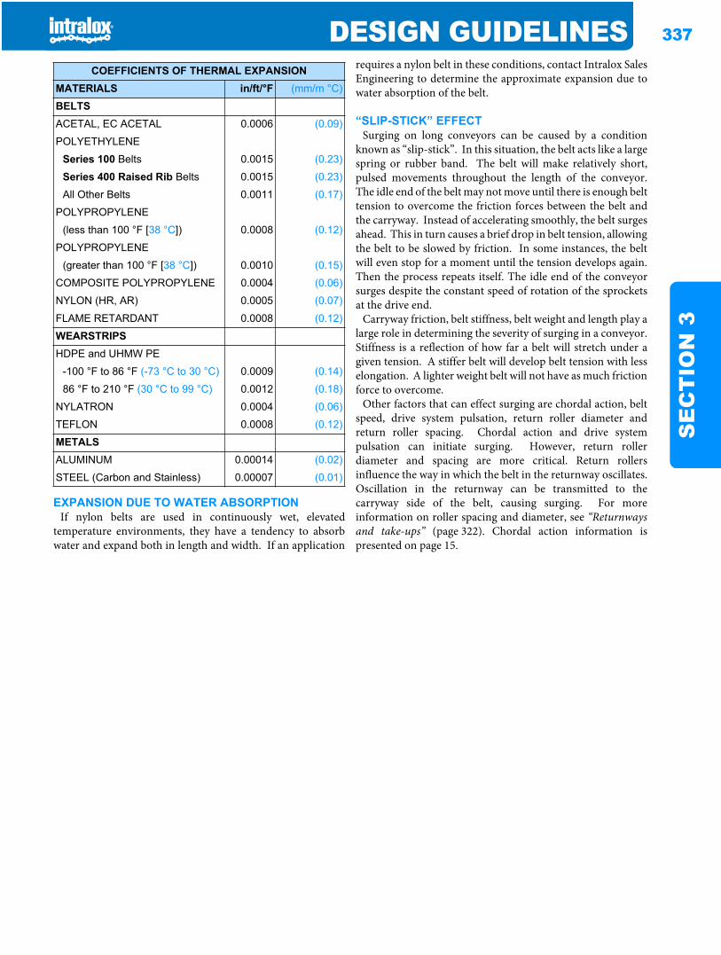
DESIGN GUIDELINES 337
SE
CT
ION
3
EXPANSION DUE TO WATER ABSORPTIONIf nylon belts are used in continuously wet, elevated
temperature environments, they have a tendency to absorbwater and expand both in length and width. If an application
requires a nylon belt in these conditions, contact Intralox SalesEngineering to determine the approximate expansion due towater absorption of the belt.
“SLIP-STICK” EFFECTSurging on long conveyors can be caused by a condition
known as “slip-stick”. In this situation, the belt acts like a largespring or rubber band. The belt will make relatively short,pulsed movements throughout the length of the conveyor.The idle end of the belt may not move until there is enough belttension to overcome the friction forces between the belt andthe carryway. Instead of accelerating smoothly, the belt surgesahead. This in turn causes a brief drop in belt tension, allowingthe belt to be slowed by friction. In some instances, the beltwill even stop for a moment until the tension develops again.Then the process repeats itself. The idle end of the conveyorsurges despite the constant speed of rotation of the sprocketsat the drive end.
Carryway friction, belt stiffness, belt weight and length play alarge role in determining the severity of surging in a conveyor.Stiffness is a reflection of how far a belt will stretch under agiven tension. A stiffer belt will develop belt tension with lesselongation. A lighter weight belt will not have as much frictionforce to overcome.
Other factors that can effect surging are chordal action, beltspeed, drive system pulsation, return roller diameter andreturn roller spacing. Chordal action and drive systempulsation can initiate surging. However, return rollerdiameter and spacing are more critical. Return rollersinfluence the way in which the belt in the returnway oscillates.Oscillation in the returnway can be transmitted to thecarryway side of the belt, causing surging. For moreinformation on roller spacing and diameter, see “Returnwaysand take-ups” (page 322). Chordal action information ispresented on page 15.
COEFFICIENTS OF THERMAL EXPANSIONMATERIALS in/ft/°F (mm/m °C)
BELTSACETAL, EC ACETAL 0.0006 (0.09)
POLYETHYLENE
Series 100 Belts 0.0015 (0.23)
Series 400 Raised Rib Belts 0.0015 (0.23)
All Other Belts 0.0011 (0.17)
POLYPROPYLENE
(less than 100 °F [38 °C]) 0.0008 (0.12)
POLYPROPYLENE
(greater than 100 °F [38 °C]) 0.0010 (0.15)
COMPOSITE POLYPROPYLENE 0.0004 (0.06)
NYLON (HR, AR) 0.0005 (0.07)
FLAME RETARDANT 0.0008 (0.12)
WEARSTRIPSHDPE and UHMW PE
-100 °F to 86 °F (-73 °C to 30 °C) 0.0009 (0.14)
86 °F to 210 °F (30 °C to 99 °C) 0.0012 (0.18)
NYLATRON 0.0004 (0.06)
TEFLON 0.0008 (0.12)
METALSALUMINUM 0.00014 (0.02)
STEEL (Carbon and Stainless) 0.00007 (0.01)

338 DESIGN GUIDELINESS
EC
TIO
N 3
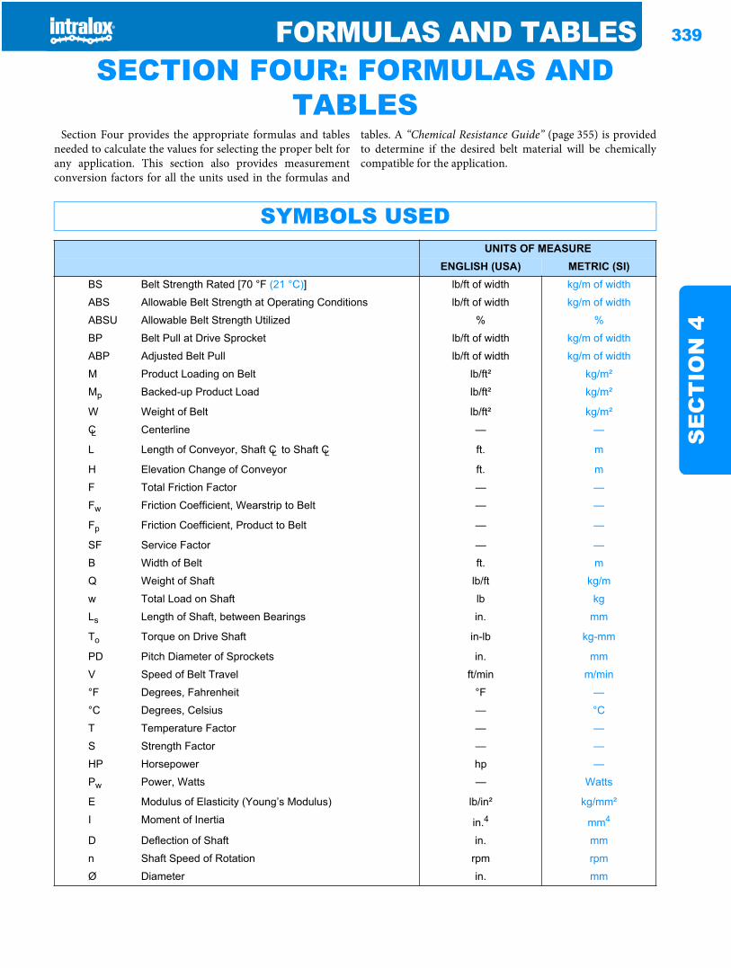
FORMULAS AND TABLES 339
SE
CT
ION
4
Formulas and tables SECTION FOUR: FORMULAS AND TABLES
Section Four provides the appropriate formulas and tablesneeded to calculate the values for selecting the proper belt forany application. This section also provides measurementconversion factors for all the units used in the formulas and
tables. A “Chemical Resistance Guide” (page 355) is providedto determine if the desired belt material will be chemicallycompatible for the application.
SYMBOLS USEDUNITS OF MEASURE
ENGLISH (USA) METRIC (SI)BS Belt Strength Rated [70 °F (21 °C)] lb/ft of width kg/m of width
ABS Allowable Belt Strength at Operating Conditions lb/ft of width kg/m of width
ABSU Allowable Belt Strength Utilized % %
BP Belt Pull at Drive Sprocket lb/ft of width kg/m of width
ABP Adjusted Belt Pull lb/ft of width kg/m of width
M Product Loading on Belt lb/ft² kg/m²
Mp Backed-up Product Load lb/ft² kg/m²
W Weight of Belt lb/ft² kg/m²
CL Centerline — —
L Length of Conveyor, Shaft CL to Shaft CL ft. m
H Elevation Change of Conveyor ft. m
F Total Friction Factor — —
Fw Friction Coefficient, Wearstrip to Belt — —
Fp Friction Coefficient, Product to Belt — —
SF Service Factor — —
B Width of Belt ft. m
Q Weight of Shaft lb/ft kg/m
w Total Load on Shaft lb kg
Ls Length of Shaft, between Bearings in. mm
To Torque on Drive Shaft in-lb kg-mm
PD Pitch Diameter of Sprockets in. mm
V Speed of Belt Travel ft/min m/min
°F Degrees, Fahrenheit °F —
°C Degrees, Celsius — °C
T Temperature Factor — —
S Strength Factor — —
HP Horsepower hp —
Pw Power, Watts — Watts
E Modulus of Elasticity (Young’s Modulus) lb/in² kg/mm²
I Moment of Inertia in.4 mm4
D Deflection of Shaft in. mm
n Shaft Speed of Rotation rpm rpm
Ø Diameter in. mm
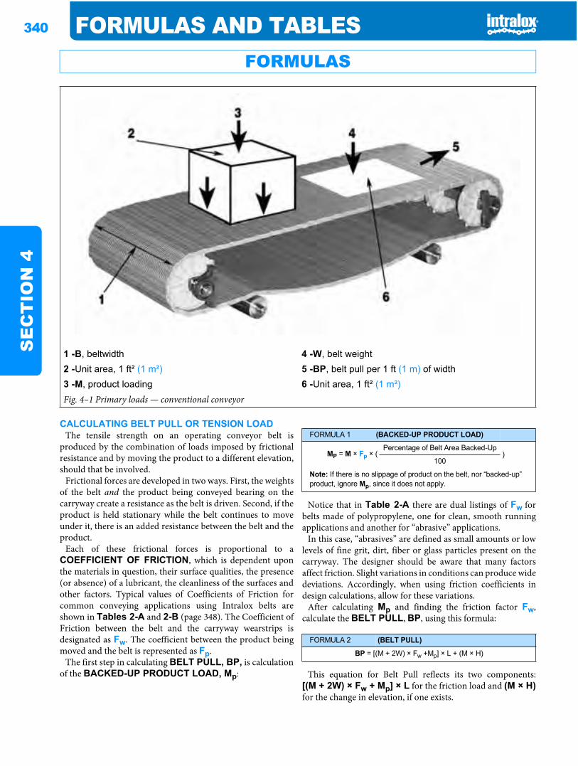
340 FORMULAS AND TABLESS
EC
TIO
N 4
CALCULATING BELT PULL OR TENSION LOADThe tensile strength on an operating conveyor belt is
produced by the combination of loads imposed by frictionalresistance and by moving the product to a different elevation,should that be involved.
Frictional forces are developed in two ways. First, the weightsof the belt and the product being conveyed bearing on thecarryway create a resistance as the belt is driven. Second, if theproduct is held stationary while the belt continues to moveunder it, there is an added resistance between the belt and theproduct.
Each of these frictional forces is proportional to aCOEFFICIENT OF FRICTION, which is dependent uponthe materials in question, their surface qualities, the presence(or absence) of a lubricant, the cleanliness of the surfaces andother factors. Typical values of Coefficients of Friction forcommon conveying applications using Intralox belts areshown in Tables 2-A and 2-B (page 348). The Coefficient ofFriction between the belt and the carryway wearstrips isdesignated as Fw. The coefficient between the product beingmoved and the belt is represented as Fp.
The first step in calculating BELT PULL, BP, is calculationof the BACKED-UP PRODUCT LOAD, Mp:
Notice that in Table 2-A there are dual listings of Fw forbelts made of polypropylene, one for clean, smooth runningapplications and another for “abrasive” applications.
In this case, “abrasives” are defined as small amounts or lowlevels of fine grit, dirt, fiber or glass particles present on thecarryway. The designer should be aware that many factorsaffect friction. Slight variations in conditions can produce widedeviations. Accordingly, when using friction coefficients indesign calculations, allow for these variations.
After calculating Mp and finding the friction factor Fw,calculate the BELT PULL, BP, using this formula:
This equation for Belt Pull reflects its two components:[(M + 2W) × Fw + Mp] × L for the friction load and (M × H)for the change in elevation, if one exists.
FORMULAS
1 -B, beltwidth 4 -W, belt weight2 -Unit area, 1 ft² (1 m²) 5 -BP, belt pull per 1 ft (1 m) of width3 -M, product loading 6 -Unit area, 1 ft² (1 m²)Fig. 4–1 Primary loads — conventional conveyor
FORMULA 1 (BACKED-UP PRODUCT LOAD)
MP = M × Fp × (Percentage of Belt Area Backed-Up
)100
Note: If there is no slippage of product on the belt, nor “backed-up” product, ignore Mp, since it does not apply.
FORMULA 2 (BELT PULL)
BP = [(M + 2W) × Fw +Mp] × L + (M × H)
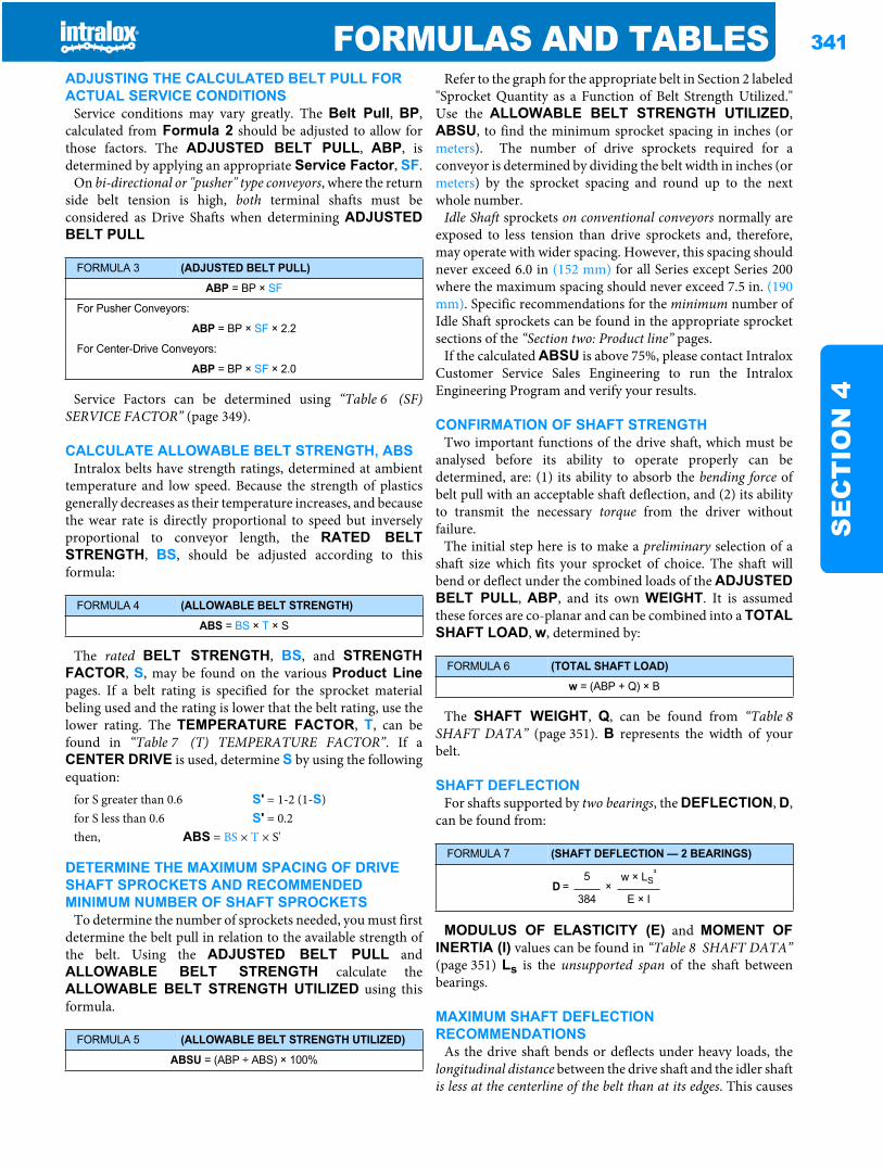
FORMULAS AND TABLES 341
SE
CT
ION
4
ADJUSTING THE CALCULATED BELT PULL FOR ACTUAL SERVICE CONDITIONS
Service conditions may vary greatly. The Belt Pull, BP,calculated from Formula 2 should be adjusted to allow forthose factors. The ADJUSTED BELT PULL, ABP, isdetermined by applying an appropriate Service Factor, SF.
On bi-directional or "pusher" type conveyors, where the returnside belt tension is high, both terminal shafts must beconsidered as Drive Shafts when determining ADJUSTEDBELT PULL
Service Factors can be determined using “Table 6 (SF)SERVICE FACTOR” (page 349).
CALCULATE ALLOWABLE BELT STRENGTH, ABSIntralox belts have strength ratings, determined at ambient
temperature and low speed. Because the strength of plasticsgenerally decreases as their temperature increases, and becausethe wear rate is directly proportional to speed but inverselyproportional to conveyor length, the RATED BELTSTRENGTH, BS, should be adjusted according to thisformula:
The rated BELT STRENGTH, BS, and STRENGTHFACTOR, S, may be found on the various Product Linepages. If a belt rating is specified for the sprocket materialbeling used and the rating is lower that the belt rating, use thelower rating. The TEMPERATURE FACTOR, T, can befound in “Table 7 (T) TEMPERATURE FACTOR”. If aCENTER DRIVE is used, determine S by using the followingequation:
DETERMINE THE MAXIMUM SPACING OF DRIVE SHAFT SPROCKETS AND RECOMMENDED MINIMUM NUMBER OF SHAFT SPROCKETS
To determine the number of sprockets needed, you must firstdetermine the belt pull in relation to the available strength ofthe belt. Using the ADJUSTED BELT PULL andALLOWABLE BELT STRENGTH calculate theALLOWABLE BELT STRENGTH UTILIZED using thisformula.
Refer to the graph for the appropriate belt in Section 2 labeled"Sprocket Quantity as a Function of Belt Strength Utilized."Use the ALLOWABLE BELT STRENGTH UTILIZED,ABSU, to find the minimum sprocket spacing in inches (ormeters). The number of drive sprockets required for aconveyor is determined by dividing the belt width in inches (ormeters) by the sprocket spacing and round up to the nextwhole number.
Idle Shaft sprockets on conventional conveyors normally areexposed to less tension than drive sprockets and, therefore,may operate with wider spacing. However, this spacing shouldnever exceed 6.0 in (152 mm) for all Series except Series 200where the maximum spacing should never exceed 7.5 in. (190mm). Specific recommendations for the minimum number ofIdle Shaft sprockets can be found in the appropriate sprocketsections of the “Section two: Product line” pages.
If the calculated ABSU is above 75%, please contact IntraloxCustomer Service Sales Engineering to run the IntraloxEngineering Program and verify your results.
CONFIRMATION OF SHAFT STRENGTHTwo important functions of the drive shaft, which must be
analysed before its ability to operate properly can bedetermined, are: (1) its ability to absorb the bending force ofbelt pull with an acceptable shaft deflection, and (2) its abilityto transmit the necessary torque from the driver withoutfailure.
The initial step here is to make a preliminary selection of ashaft size which fits your sprocket of choice. The shaft willbend or deflect under the combined loads of the ADJUSTEDBELT PULL, ABP, and its own WEIGHT. It is assumedthese forces are co-planar and can be combined into a TOTALSHAFT LOAD, w, determined by:
The SHAFT WEIGHT, Q, can be found from “Table 8SHAFT DATA” (page 351). B represents the width of yourbelt.
SHAFT DEFLECTIONFor shafts supported by two bearings, the DEFLECTION, D,
can be found from:
MODULUS OF ELASTICITY (E) and MOMENT OFINERTIA (I) values can be found in “Table 8 SHAFT DATA”(page 351) Ls is the unsupported span of the shaft betweenbearings.
MAXIMUM SHAFT DEFLECTION RECOMMENDATIONS
As the drive shaft bends or deflects under heavy loads, thelongitudinal distance between the drive shaft and the idler shaftis less at the centerline of the belt than at its edges. This causes
FORMULA 3 (ADJUSTED BELT PULL)
ABP = BP × SF
For Pusher Conveyors:
ABP = BP × SF × 2.2
For Center-Drive Conveyors:
ABP = BP × SF × 2.0
FORMULA 4 (ALLOWABLE BELT STRENGTH)
ABS = BS × T × S
for S greater than 0.6 S' = 1-2 (1-S)for S less than 0.6 S' = 0.2then, ABS = BS × T × S'
FORMULA 5 (ALLOWABLE BELT STRENGTH UTILIZED)
ABSU = (ABP ÷ ABS) × 100%
FORMULA 6 (TOTAL SHAFT LOAD)
w = (ABP + Q) × B
FORMULA 7 (SHAFT DEFLECTION — 2 BEARINGS)
D = 5
×w × LS
³
384 E × I
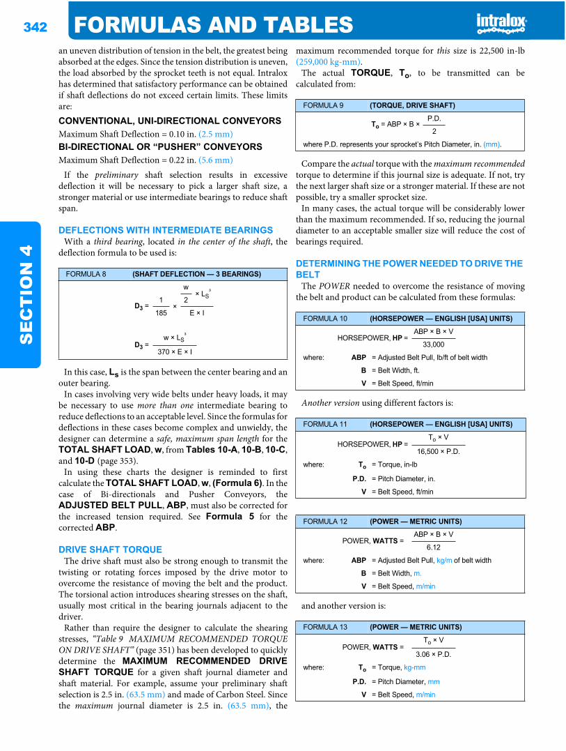
342 FORMULAS AND TABLESS
EC
TIO
N 4
an uneven distribution of tension in the belt, the greatest beingabsorbed at the edges. Since the tension distribution is uneven,the load absorbed by the sprocket teeth is not equal. Intraloxhas determined that satisfactory performance can be obtainedif shaft deflections do not exceed certain limits. These limitsare:
If the preliminary shaft selection results in excessivedeflection it will be necessary to pick a larger shaft size, astronger material or use intermediate bearings to reduce shaftspan.
DEFLECTIONS WITH INTERMEDIATE BEARINGSWith a third bearing, located in the center of the shaft, the
deflection formula to be used is:
In this case, Ls is the span between the center bearing and anouter bearing.
In cases involving very wide belts under heavy loads, it maybe necessary to use more than one intermediate bearing toreduce deflections to an acceptable level. Since the formulas fordeflections in these cases become complex and unwieldy, thedesigner can determine a safe, maximum span length for theTOTAL SHAFT LOAD, w, from Tables 10-A, 10-B, 10-C,and 10-D (page 353).
In using these charts the designer is reminded to firstcalculate the TOTAL SHAFT LOAD, w, (Formula 6). In thecase of Bi-directionals and Pusher Conveyors, theADJUSTED BELT PULL, ABP, must also be corrected forthe increased tension required. See Formula 5 for thecorrected ABP.
DRIVE SHAFT TORQUEThe drive shaft must also be strong enough to transmit the
twisting or rotating forces imposed by the drive motor toovercome the resistance of moving the belt and the product.The torsional action introduces shearing stresses on the shaft,usually most critical in the bearing journals adjacent to thedriver.
Rather than require the designer to calculate the shearingstresses, “Table 9 MAXIMUM RECOMMENDED TORQUEON DRIVE SHAFT” (page 351) has been developed to quicklydetermine the MAXIMUM RECOMMENDED DRIVESHAFT TORQUE for a given shaft journal diameter andshaft material. For example, assume your preliminary shaftselection is 2.5 in. (63.5 mm) and made of Carbon Steel. Sincethe maximum journal diameter is 2.5 in. (63.5 mm), the
maximum recommended torque for this size is 22,500 in-lb(259,000 kg-mm).
The actual TORQUE, To, to be transmitted can becalculated from:
Compare the actual torque with the maximum recommendedtorque to determine if this journal size is adequate. If not, trythe next larger shaft size or a stronger material. If these are notpossible, try a smaller sprocket size.
In many cases, the actual torque will be considerably lowerthan the maximum recommended. If so, reducing the journaldiameter to an acceptable smaller size will reduce the cost ofbearings required.
DETERMINING THE POWER NEEDED TO DRIVE THE BELT
The POWER needed to overcome the resistance of movingthe belt and product can be calculated from these formulas:
Another version using different factors is:
and another version is:
CONVENTIONAL, UNI-DIRECTIONAL CONVEYORSMaximum Shaft Deflection = 0.10 in. (2.5 mm)BI-DIRECTIONAL OR “PUSHER” CONVEYORSMaximum Shaft Deflection = 0.22 in. (5.6 mm)
FORMULA 8 (SHAFT DEFLECTION — 3 BEARINGS)
w × LS
³
D3 = 1
×2
185 E × I
w × LS³
D3 = 370 × E × I
FORMULA 9 (TORQUE, DRIVE SHAFT)
To = ABP × B ×P.D.
2
where P.D. represents your sprocket’s Pitch Diameter, in. (mm).
FORMULA 10 (HORSEPOWER — ENGLISH [USA] UNITS)
HORSEPOWER, HP = ABP × B × V
33,000
where: ABP = Adjusted Belt Pull, lb/ft of belt width
B = Belt Width, ft.
V = Belt Speed, ft/min
FORMULA 11 (HORSEPOWER — ENGLISH [USA] UNITS)
HORSEPOWER, HP = To × V
16,500 × P.D.
where: To = Torque, in-lb
P.D. = Pitch Diameter, in.
V = Belt Speed, ft/min
FORMULA 12 (POWER — METRIC UNITS)
POWER, WATTS = ABP × B × V
6.12
where: ABP = Adjusted Belt Pull, kg/m of belt width
B = Belt Width, m.
V = Belt Speed, m/min
FORMULA 13 (POWER — METRIC UNITS)
POWER, WATTS = To × V
3.06 × P.D.
where: To = Torque, kg-mm
P.D. = Pitch Diameter, mm
V = Belt Speed, m/min
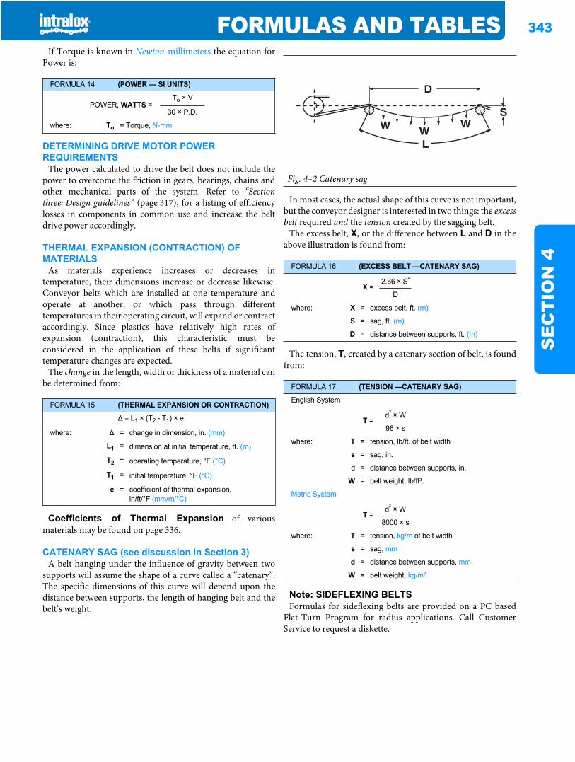
FORMULAS AND TABLES 343
SE
CT
ION
4
If Torque is known in Newton-millimeters the equation forPower is:
DETERMINING DRIVE MOTOR POWER REQUIREMENTS
The power calculated to drive the belt does not include thepower to overcome the friction in gears, bearings, chains andother mechanical parts of the system. Refer to “Sectionthree: Design guidelines” (page 317), for a listing of efficiencylosses in components in common use and increase the beltdrive power accordingly.
THERMAL EXPANSION (CONTRACTION) OF MATERIALS
As materials experience increases or decreases intemperature, their dimensions increase or decrease likewise.Conveyor belts which are installed at one temperature andoperate at another, or which pass through differenttemperatures in their operating circuit, will expand or contractaccordingly. Since plastics have relatively high rates ofexpansion (contraction), this characteristic must beconsidered in the application of these belts if significanttemperature changes are expected.
The change in the length, width or thickness of a material canbe determined from:
Coefficients of Thermal Expansion of variousmaterials may be found on page 336.
CATENARY SAG (see discussion in Section 3)A belt hanging under the influence of gravity between two
supports will assume the shape of a curve called a “catenary”.The specific dimensions of this curve will depend upon thedistance between supports, the length of hanging belt and thebelt’s weight.
In most cases, the actual shape of this curve is not important,but the conveyor designer is interested in two things: the excessbelt required and the tension created by the sagging belt.
The excess belt, X, or the difference between L and D in theabove illustration is found from:
The tension, T, created by a catenary section of belt, is foundfrom:
Note: SIDEFLEXING BELTSFormulas for sideflexing belts are provided on a PC based
Flat-Turn Program for radius applications. Call CustomerService to request a diskette.
FORMULA 14 (POWER — SI UNITS)
POWER, WATTS = To × V
30 × P.D.
where: To = Torque, N-mm
FORMULA 15 (THERMAL EXPANSION OR CONTRACTION)
= L1 × (T2 - T1) × e
where: = change in dimension, in. (mm)
L1 = dimension at initial temperature, ft. (m)
T2 = operating temperature, °F (°C)
T1 = initial temperature, °F (°C)
e = coefficient of thermal expansion,in/ft/°F (mm/m/°C)
Fig. 4–2 Catenary sag
FORMULA 16 (EXCESS BELT —CATENARY SAG)
X = 2.66 × S²
D
where: X = excess belt, ft. (m)
S = sag, ft. (m)
D = distance between supports, ft. (m)
FORMULA 17 (TENSION —CATENARY SAG)
English System
T = d² × W
96 × s
where: T = tension, lb/ft. of belt width
s = sag, in.
d = distance between supports, in.
W = belt weight, lb/ft².
Metric System
T = d² × W
8000 × s
where: T = tension, kg/m of belt width
s = sag, mm
d = distance between supports, mm
W = belt weight, kg/m²
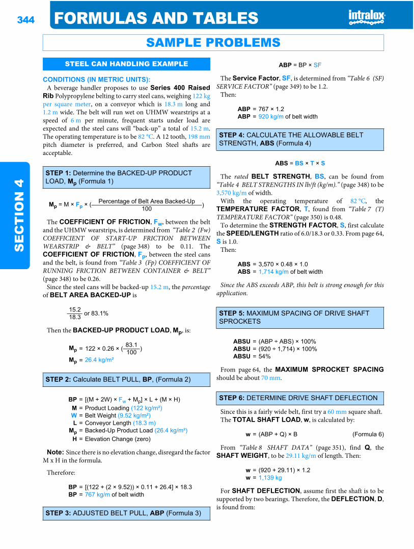
344 FORMULAS AND TABLESS
EC
TIO
N 4
CONDITIONS (IN METRIC UNITS):A beverage handler proposes to use Series 400 Raised
Rib Polypropylene belting to carry steel cans, weighing 122 kgper square meter, on a conveyor which is 18.3 m long and1.2 m wide. The belt will run wet on UHMW wearstrips at aspeed of 6 m per minute, frequent starts under load areexpected and the steel cans will “back-up” a total of 15.2 m.The operating temperature is to be 82 °C. A 12 tooth, 198 mmpitch diameter is preferred, and Carbon Steel shafts areacceptable.
The COEFFICIENT OF FRICTION, Fw, between the beltand the UHMW wearstrips, is determined from “Table 2 (Fw)COEFFICIENT OF START-UP FRICTION BETWEENWEARSTRIP & BELT” (page 348) to be 0.11. TheCOEFFICIENT OF FRICTION, Fp, between the steel cansand the belt, is found from “Table 3 (Fp) COEFFICIENT OFRUNNING FRICTION BETWEEN CONTAINER & BELT”(page 348) to be 0.26.
Since the steel cans will be backed-up 15.2 m, the percentageof BELT AREA BACKED-UP is
Then the BACKED-UP PRODUCT LOAD, Mp, is:
Note: Since there is no elevation change, disregard the factorM x H in the formula.
Therefore:
The Service Factor, SF, is determined from “Table 6 (SF)SERVICE FACTOR” (page 349) to be 1.2.
Then:
The rated BELT STRENGTH, BS, can be found from“Table 4 BELT STRENGTHS IN lb/ft (kg/m).” (page 348) to be3,570 kg/m of width.
With the operating temperature of 82 °C, theTEMPERATURE FACTOR, T, found from “Table 7 (T)TEMPERATURE FACTOR” (page 350) is 0.48.
To determine the STRENGTH FACTOR, S, first calculatethe SPEED/LENGTH ratio of 6.0/18.3 or 0.33. From page 64,S is 1.0.
Then:
Since the ABS exceeds ABP, this belt is strong enough for thisapplication.
From page 64, the MAXIMUM SPROCKET SPACINGshould be about 70 mm.
Since this is a fairly wide belt, first try a 60 mm square shaft.The TOTAL SHAFT LOAD, w, is calculated by:
From “Table 8 SHAFT DATA” (page 351), find Q, theSHAFT WEIGHT, to be 29.11 kg/m of length. Then:
For SHAFT DEFLECTION, assume first the shaft is to besupported by two bearings. Therefore, the DEFLECTION, D,is found from:
SAMPLE PROBLEMSSTEEL CAN HANDLING EXAMPLE
STEP 1: Determine the BACKED-UP PRODUCT LOAD, Mp (Formula 1)
Mp = M × Fp × ( Percentage of Belt Area Backed-Up )100
15.2 or 83.1%18.3
Mp = 122 × 0.26 × ( 83.1 )100Mp = 26.4 kg/m²
STEP 2: Calculate BELT PULL, BP, (Formula 2)
BP = [(M + 2W) × Fw + Mp] × L + (M × H)M = Product Loading (122 kg/m²)W = Belt Weight (9.52 kg/m²)L = Conveyor Length (18.3 m)
Mp = Backed-Up Product Load (26.4 kg/m²)H = Elevation Change (zero)
BP = [(122 + (2 × 9.52)) × 0.11 + 26.4] × 18.3BP = 767 kg/m of belt width
STEP 3: ADJUSTED BELT PULL, ABP (Formula 3)
ABP = BP × SF
ABP = 767 × 1.2ABP = 920 kg/m of belt width
STEP 4: CALCULATE THE ALLOWABLE BELT STRENGTH, ABS (Formula 4)
ABS = BS × T × S
ABS = 3,570 × 0.48 × 1.0ABS = 1,714 kg/m of belt width
STEP 5: MAXIMUM SPACING OF DRIVE SHAFT SPROCKETS
ABSU = (ABP ÷ ABS) × 100%ABSU = (920 ÷ 1,714) × 100%ABSU = 54%
STEP 6: DETERMINE DRIVE SHAFT DEFLECTION
w = (ABP + Q) × B (Formula 6)
w = (920 + 29.11) × 1.2w = 1,139 kg
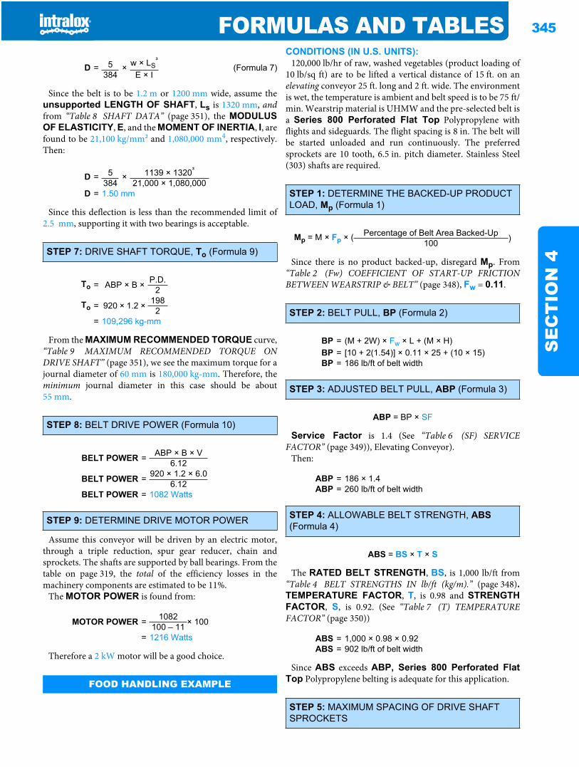
FORMULAS AND TABLES 345
SE
CT
ION
4
Since the belt is to be 1.2 m or 1200 mm wide, assume theunsupported LENGTH OF SHAFT, Ls is 1320 mm, andfrom “Table 8 SHAFT DATA” (page 351), the MODULUSOF ELASTICITY, E, and the MOMENT OF INERTIA, I, arefound to be 21,100 kg/mm2 and 1,080,000 mm4, respectively.Then:
Since this deflection is less than the recommended limit of2.5 mm, supporting it with two bearings is acceptable.
From the MAXIMUM RECOMMENDED TORQUE curve,“Table 9 MAXIMUM RECOMMENDED TORQUE ONDRIVE SHAFT” (page 351), we see the maximum torque for ajournal diameter of 60 mm is 180,000 kg-mm. Therefore, theminimum journal diameter in this case should be about55 mm.
Assume this conveyor will be driven by an electric motor,through a triple reduction, spur gear reducer, chain andsprockets. The shafts are supported by ball bearings. From thetable on page 319, the total of the efficiency losses in themachinery components are estimated to be 11%.
The MOTOR POWER is found from:
Therefore a 2 kW motor will be a good choice.
CONDITIONS (IN U.S. UNITS):120,000 lb/hr of raw, washed vegetables (product loading of
10 lb/sq ft) are to be lifted a vertical distance of 15 ft. on anelevating conveyor 25 ft. long and 2 ft. wide. The environmentis wet, the temperature is ambient and belt speed is to be 75 ft/min. Wearstrip material is UHMW and the pre-selected belt isa Series 800 Perforated Flat Top Polypropylene withflights and sideguards. The flight spacing is 8 in. The belt willbe started unloaded and run continuously. The preferredsprockets are 10 tooth, 6.5 in. pitch diameter. Stainless Steel(303) shafts are required.
Since there is no product backed-up, disregard Mp. From“Table 2 (Fw) COEFFICIENT OF START-UP FRICTIONBETWEEN WEARSTRIP & BELT” (page 348), Fw = 0.11.
Service Factor is 1.4 (See “Table 6 (SF) SERVICEFACTOR” (page 349)), Elevating Conveyor).
Then:
The RATED BELT STRENGTH, BS, is 1,000 lb/ft from“Table 4 BELT STRENGTHS IN lb/ft (kg/m).” (page 348).TEMPERATURE FACTOR, T, is 0.98 and STRENGTHFACTOR, S, is 0.92. (See “Table 7 (T) TEMPERATUREFACTOR” (page 350))
Since ABS exceeds ABP, Series 800 Perforated FlatTop Polypropylene belting is adequate for this application.
D = 5 × w × LS³
(Formula 7)384 E × I
D = 5 × 1139 × 1320³
384 21,000 × 1,080,000D = 1.50 mm
STEP 7: DRIVE SHAFT TORQUE, To (Formula 9)
To = ABP × B × P.D.2
To = 920 × 1.2 × 1982
= 109,296 kg-mm
STEP 8: BELT DRIVE POWER (Formula 10)
BELT POWER = ABP × B × V6.12
BELT POWER = 920 × 1.2 × 6.06.12
BELT POWER = 1082 Watts
STEP 9: DETERMINE DRIVE MOTOR POWER
MOTOR POWER = 1082 × 100100 – 11= 1216 Watts
FOOD HANDLING EXAMPLE
STEP 1: DETERMINE THE BACKED-UP PRODUCT LOAD, Mp (Formula 1)
Mp = M × Fp × ( Percentage of Belt Area Backed-Up )100
STEP 2: BELT PULL, BP (Formula 2)
BP = (M + 2W) × Fw × L + (M × H)BP = [10 + 2(1.54)] × 0.11 × 25 + (10 × 15)BP = 186 lb/ft of belt width
STEP 3: ADJUSTED BELT PULL, ABP (Formula 3)
ABP = BP × SF
ABP = 186 × 1.4ABP = 260 lb/ft of belt width
STEP 4: ALLOWABLE BELT STRENGTH, ABS(Formula 4)
ABS = BS × T × S
ABS = 1,000 × 0.98 × 0.92ABS = 902 lb/ft of belt width
STEP 5: MAXIMUM SPACING OF DRIVE SHAFT SPROCKETS
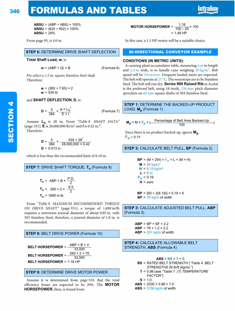
346 FORMULAS AND TABLESS
EC
TIO
N 4
From page 95, is 4.0 in.
Total Shaft Load, w, is:
Pre-select a 1.5 in. square Stainless Steel shaft.Therefore:
and SHAFT DEFLECTION, D, is:
Assume Ls is 28 in. From “Table 8 SHAFT DATA”(page 351), E is 28,000,000 lb/in2 and I is 0.42 in.4.
Therefore:
which is less than the recommended limit of 0.10 in.
From “Table 9 MAXIMUM RECOMMENDED TORQUEON DRIVE SHAFT” (page 351), a torque of 1,690 in/lbrequires a minimum journal diameter of about 0.85 in. with303 Stainless Steel, therefore, a journal diameter of 1.0 in. isrecommended.
Assume it is determined from page 319, that the totalefficiency losses are expected to be 20%. The MOTORHORSEPOWER, then, is found from:
In this case, a 1.5 HP motor will be a suitable choice.
CONDITIONS (IN METRIC UNITS):A canning plant accumulator table, measuring 6 m in length
and 2.4 m wide, is to handle cans weighing 50 kg/m2. Beltspeed will be 3.0 m/min. Frequent loaded starts are expected.The belt will operate at 21 °C. The wearstrips are to be StainlessSteel. The belt will run dry. Series 900 Raised Rib in Acetalis the preferred belt, using 18 tooth, 156 mm pitch diametersprockets on 60 mm square shafts of 304 Stainless Steel.
Since there is no product backed-up, ignore Mp.Fw = 0.19
ABSU = (ABP ÷ ABS) × 100%ABSU = (620 ÷ 902) × 100%ABSU = 29%
STEP 6: DETERMINE DRIVE SHAFT DEFLECTION
w = (ABP + Q) × B (Formula 6)
w = (260 + 7.65) × 2w = 535 lb
D = 5 × w × LS³
(Formula 7)384 E × I
D = 5 × 535 × 28³
384 28,000,000 × 0.42D = 0.013 in.
STEP 7: DRIVE SHAFT TORQUE, To (Formula 9)
To = ABP × B × P.D.2
To = 260 × 2 × 6.52
To = 1690 in-lb
STEP 8: BELT DRIVE POWER (Formula 10)
BELT HORSEPOWER = ABP × B × V33,000
BELT HORSEPOWER = 260 × 2 × 7533,000
BELT HORSEPOWER = 1.18 HP
STEP 9: DETERMINE DRIVE MOTOR POWER
MOTOR HORSEPOWER = 1,18 × 100100 – 20= 1,48 HP
BI-DIRECTIONAL CONVEYOR EXAMPLE
STEP 1: DETERMINE THE BACKED-UP PRODUCT LOAD, Mp (Formula 1)
Mp = M × Fp × ( Percentage of Belt Area Backed-Up )100
STEP 2: CALCULATE BELT PULL, BP (Formula 2)
BP = (M + 2W) × Fw × L + (M × H)M = 50 kg/m²W = 8.19 kg/m²L = 6 m
Fw = 0.19H = zero
BP = [50 + 2(8.19)] × 0.19 × 6BP = 76 kg/m of width
STEP 3: CALCULATE ADJUSTED BELT PULL, ABP(Formula 3)
ABP = BP × SF × 2.2ABP = 76 × 1.2 × 2.2ABP = 201 kg/m of width
STEP 4: CALCULATE ALLOWABLE BELT STRENGTH, ABS (Formula 4)
ABS = BS × T × SBS = RATED BELT STRENGTH (“Table 4 BELT
STRENGTHS IN lb/ft (kg/m).”)T = 0.98 (see “Table 7 (T) TEMPERATURE
FACTOR”)S = 1.0
ABS = 2200 × 0.98 × 1.0ABS = 2156 kg/m of width
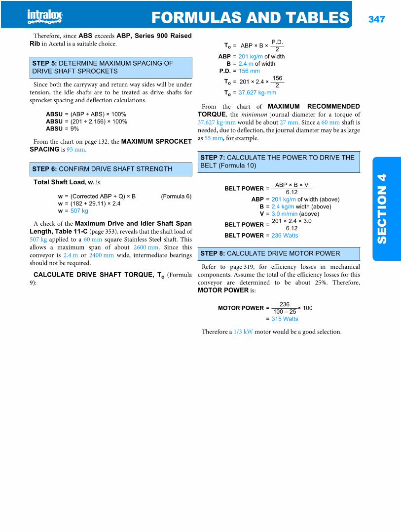
FORMULAS AND TABLES 347
SE
CT
ION
4
Therefore, since ABS exceeds ABP, Series 900 RaisedRib in Acetal is a suitable choice.
Since both the carryway and return way sides will be undertension, the idle shafts are to be treated as drive shafts forsprocket spacing and deflection calculations.
From the chart on page 132, the MAXIMUM SPROCKETSPACING is 95 mm.
Total Shaft Load, w, is:
A check of the Maximum Drive and Idler Shaft SpanLength, Table 11-C (page 353), reveals that the shaft load of507 kg applied to a 60 mm square Stainless Steel shaft. Thisallows a maximum span of about 2600 mm. Since thisconveyor is 2.4 m or 2400 mm wide, intermediate bearingsshould not be required.
CALCULATE DRIVE SHAFT TORQUE, To (Formula9):
From the chart of MAXIMUM RECOMMENDEDTORQUE, the minimum journal diameter for a torque of37,627 kg-mm would be about 27 mm. Since a 60 mm shaft isneeded, due to deflection, the journal diameter may be as largeas 55 mm, for example.
Refer to page 319, for efficiency losses in mechanicalcomponents. Assume the total of the efficiency losses for thisconveyor are determined to be about 25%. Therefore,MOTOR POWER is:
Therefore a 1/3 kW motor would be a good selection.
STEP 5: DETERMINE MAXIMUM SPACING OF DRIVE SHAFT SPROCKETS
ABSU = (ABP ÷ ABS) × 100%ABSU = (201 ÷ 2,156) × 100%ABSU = 9%
STEP 6: CONFIRM DRIVE SHAFT STRENGTH
w = (Corrected ABP + Q) × B (Formula 6)w = (182 + 29.11) × 2.4w = 507 kg
To = ABP × B × P.D.2
ABP = 201 kg/m of widthB = 2.4 m of width
P.D. = 156 mm
To = 201 × 2.4 × 1562
To = 37,627 kg-mm
STEP 7: CALCULATE THE POWER TO DRIVE THE BELT (Formula 10)
BELT POWER = ABP × B × V6.12
ABP = 201 kg/m of width (above)B = 2.4 kg/m width (above)V = 3.0 m/min (above)
BELT POWER = 201 × 2.4 × 3.06.12
BELT POWER = 236 Watts
STEP 8: CALCULATE DRIVE MOTOR POWER
MOTOR POWER = 236 × 100100 – 25= 315 Watts
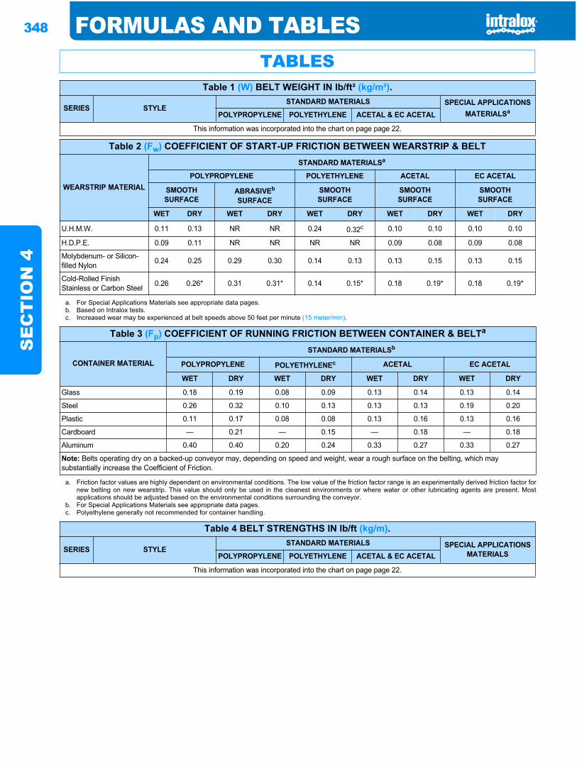
348 FORMULAS AND TABLESS
EC
TIO
N 4
TABLESTable 1 (W) BELT WEIGHT IN lb/ft² (kg/m²).
SERIES STYLESTANDARD MATERIALS SPECIAL APPLICATIONS
MATERIALSaPOLYPROPYLENE POLYETHYLENE ACETAL & EC ACETAL
This information was incorporated into the chart on page page 22.
Table 2 (Fw) COEFFICIENT OF START-UP FRICTION BETWEEN WEARSTRIP & BELT
WEARSTRIP MATERIAL
STANDARD MATERIALSa
POLYPROPYLENE POLYETHYLENE ACETAL EC ACETAL
SMOOTHSURFACE
ABRASIVEb
SURFACESMOOTHSURFACE
SMOOTHSURFACE
SMOOTHSURFACE
WET DRY WET DRY WET DRY WET DRY WET DRY
U.H.M.W. 0.11 0.13 NR NR 0.24 0.32c 0.10 0.10 0.10 0.10
H.D.P.E. 0.09 0.11 NR NR NR NR 0.09 0.08 0.09 0.08
Molybdenum- or Silicon-filled Nylon 0.24 0.25 0.29 0.30 0.14 0.13 0.13 0.15 0.13 0.15
Cold-Rolled Finish Stainless or Carbon Steel 0.26 0.26* 0.31 0.31* 0.14 0.15* 0.18 0.19* 0.18 0.19*
a. For Special Applications Materials see appropriate data pages.b. Based on Intralox tests.c. Increased wear may be experienced at belt speeds above 50 feet per minute (15 meter/min).
Table 3 (Fp) COEFFICIENT OF RUNNING FRICTION BETWEEN CONTAINER & BELTa
CONTAINER MATERIAL
STANDARD MATERIALSb
POLYPROPYLENE POLYETHYLENEc ACETAL EC ACETAL
WET DRY WET DRY WET DRY WET DRY
Glass 0.18 0.19 0.08 0.09 0.13 0.14 0.13 0.14
Steel 0.26 0.32 0.10 0.13 0.13 0.13 0.19 0.20
Plastic 0.11 0.17 0.08 0.08 0.13 0.16 0.13 0.16
Cardboard — 0.21 — 0.15 — 0.18 — 0.18
Aluminum 0.40 0.40 0.20 0.24 0.33 0.27 0.33 0.27
Note: Belts operating dry on a backed-up conveyor may, depending on speed and weight, wear a rough surface on the belting, which may substantially increase the Coefficient of Friction.
a. Friction factor values are highly dependent on environmental conditions. The low value of the friction factor range is an experimentally derived friction factor fornew belting on new wearstrip. This value should only be used in the cleanest environments or where water or other lubricating agents are present. Mostapplications should be adjusted based on the environmental conditions surrounding the conveyor.
b. For Special Applications Materials see appropriate data pages.c. Polyethylene generally not recommended for container handling.
Table 4 BELT STRENGTHS IN lb/ft (kg/m).
SERIES STYLESTANDARD MATERIALS SPECIAL APPLICATIONS
MATERIALSPOLYPROPYLENE POLYETHYLENE ACETAL & EC ACETAL
This information was incorporated into the chart on page page 22.
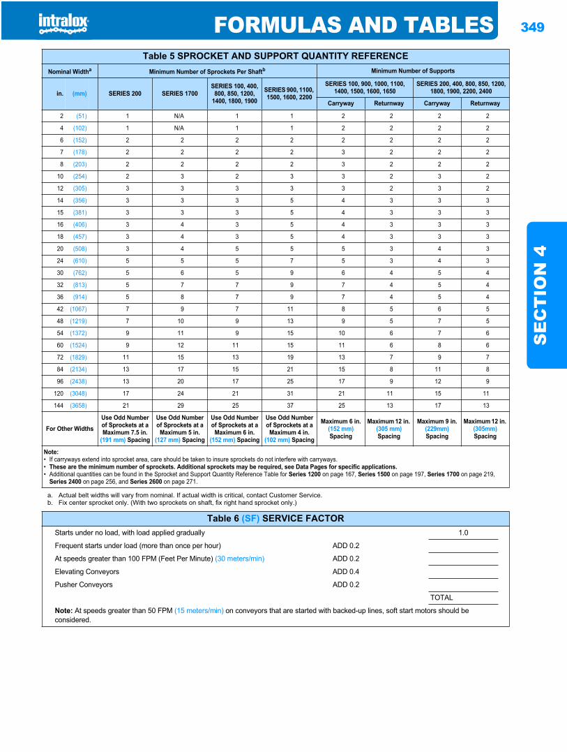
FORMULAS AND TABLES 349
SE
CT
ION
4
Table 5 SPROCKET AND SUPPORT QUANTITY REFERENCENominal Widtha Minimum Number of Sprockets Per Shaftb Minimum Number of Supports
in. (mm) SERIES 200 SERIES 1700SERIES 100, 400,
800, 850, 1200, 1400, 1800, 1900
SERIES 900, 1100, 1500, 1600, 2200
SERIES 100, 900, 1000, 1100, 1400, 1500, 1600, 1650
SERIES 200, 400, 800, 850, 1200, 1800, 1900, 2200, 2400
Carryway Returnway Carryway Returnway
2 (51) 1 N/A 1 1 2 2 2 2
4 (102) 1 N/A 1 1 2 2 2 2
6 (152) 2 2 2 2 2 2 2 2
7 (178) 2 2 2 2 3 2 2 2
8 (203) 2 2 2 2 3 2 2 2
10 (254) 2 3 2 3 3 2 3 2
12 (305) 3 3 3 3 3 2 3 2
14 (356) 3 3 3 5 4 3 3 3
15 (381) 3 3 3 5 4 3 3 3
16 (406) 3 4 3 5 4 3 3 3
18 (457) 3 4 3 5 4 3 3 3
20 (508) 3 4 5 5 5 3 4 3
24 (610) 5 5 5 7 5 3 4 3
30 (762) 5 6 5 9 6 4 5 4
32 (813) 5 7 7 9 7 4 5 4
36 (914) 5 8 7 9 7 4 5 4
42 (1067) 7 9 7 11 8 5 6 5
48 (1219) 7 10 9 13 9 5 7 5
54 (1372) 9 11 9 15 10 6 7 6
60 (1524) 9 12 11 15 11 6 8 6
72 (1829) 11 15 13 19 13 7 9 7
84 (2134) 13 17 15 21 15 8 11 8
96 (2438) 13 20 17 25 17 9 12 9
120 (3048) 17 24 21 31 21 11 15 11
144 (3658) 21 29 25 37 25 13 17 13
For Other WidthsUse Odd Number of Sprockets at a Maximum 7.5 in.
(191 mm) Spacing
Use Odd Number of Sprockets at a
Maximum 5 in. (127 mm) Spacing
Use Odd Number of Sprockets at a
Maximum 6 in. (152 mm) Spacing
Use Odd Number of Sprockets at a
Maximum 4 in. (102 mm) Spacing
Maximum 6 in. (152 mm)Spacing
Maximum 12 in. (305 mm)Spacing
Maximum 9 in. (229mm)Spacing
Maximum 12 in. (305mm)Spacing
Note:• If carryways extend into sprocket area, care should be taken to insure sprockets do not interfere with carryways.• These are the minimum number of sprockets. Additional sprockets may be required, see Data Pages for specific applications.• Additional quantities can be found in the Sprocket and Support Quantity Reference Table for Series 1200 on page 167, Series 1500 on page 197, Series 1700 on page 219,
Series 2400 on page 256, and Series 2600 on page 271.
a. Actual belt widths will vary from nominal. If actual width is critical, contact Customer Service.b. Fix center sprocket only. (With two sprockets on shaft, fix right hand sprocket only.)
Table 6 (SF) SERVICE FACTORStarts under no load, with load applied gradually 1.0
Frequent starts under load (more than once per hour) ADD 0.2
At speeds greater than 100 FPM (Feet Per Minute) (30 meters/min) ADD 0.2
Elevating Conveyors ADD 0.4
Pusher Conveyors ADD 0.2
TOTAL
Note: At speeds greater than 50 FPM (15 meters/min) on conveyors that are started with backed-up lines, soft start motors should be considered.
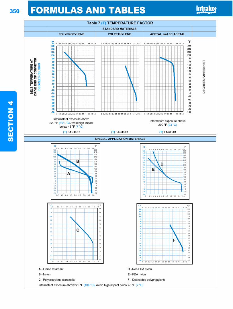
350 FORMULAS AND TABLESS
EC
TIO
N 4
Table 7 (T) TEMPERATURE FACTORSTANDARD MATERIALS
POLYPROPYLENE POLYETHYLENE ACETAL and EC ACETALBE
LT T
EMPE
RATU
RE A
TDR
IVE
END
OF
CONV
EYO
RDE
GRE
ES C
ELSI
US
DEG
REES
FAH
RENH
EIT
Intermittent exposure above220 °F (104 °C) Avoid high impact
below 45 °F (7 °C)
Intermittent exposure above200 °F (93 °C)
(T) FACTOR (T) FACTOR (T) FACTOR
SPECIAL APPLICATION MATERIALS
A - Flame retardant D - Non FDA nylon
B - Nylon E - FDA nylon
C - Polypropylene composite F - Detectable polypropylene
Intermittent exposure above220 °F (104 °C). Avoid high impact below 45 °F (7 °C)
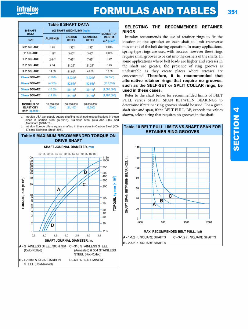
FORMULAS AND TABLES 351
SE
CT
ION
4
SELECTING THE RECOMMENDED RETAINERRINGS
Intralox recommends the use of retainer rings to fix thelocation of one sprocket on each shaft to limit transversemovement of the belt during operation. In many applications,spring-type rings are used with success; however these ringsrequire small grooves to be cut into the corners of the shafts. Insome applications where belt loads are higher and stresses inthe shaft are greater, the presence of ring grooves isundesirable as they create places where stresses areconcentrated. Therefore, it is recommended thatalternative retainer rings that require no grooves,such as the SELF-SET or SPLIT COLLAR rings, beused in these cases.
Refer to the chart below for recommended limits of BELTPULL versus SHAFT SPAN BETWEEN BEARINGS todetermine if retainer ring grooves should be used. For a givenshaft size and span, if the BELT PULL, BP, exceeds the valuesshown, select a ring that requires no grooves in the shaft.
Table 8 SHAFT DATAB-SHAFT
DATA(Q) SHAFT WEIGHT, lb/ft (kg/m) I
MOMENT OFINERTIA
in.4 (mm4)ALUMINUM CARBON
STEELSTAINLESS
STEELSIZE
5/8" SQUARE 0.46 1.33a
a. Intralox USA can supply square shafting machined to specifications in thesesizes in Carbon Steel (C-1018), Stainless Steel (303 and 316), andAluminum (6061-T6).
1.33a 0.013
1" SQUARE 1.17a 3.40a 3.40a 0.083
1.5" SQUARE 2.64a 7.65a 7.65a 0.42
2.5" SQUARE 7.34 21.25a 21.25a 3.25
3.5" SQUARE 14.39 41.60a 41.60 12.50
25 mm SQUARE (1.699) (4.920)b
b. Intralox Europe offers square shafting in these sizes in Carbon Steel (KG-37) and Stainless Steel (304).
(4.920)b (32.550)
40 mm SQUARE (4.335) (12.55)b (12.55)b (213,300)
60 mm SQUARE (10.05) (29.11)b (29.11)b (1,080,000)
65 mm SQUARE (11.79) (34.16)b (34.16)b (1,487,600)
EMODULUS OFELASTICITY
lb/ln² (kg/mm²)
10,000,000(7000)
30,000,000(21,100)
28,000,000(19,700)
Table 9 MAXIMUM RECOMMENDED TORQUE ON DRIVE SHAFT
SHAFT JOURNAL DIAMETER, mm
TORQ
UE, i
n-lb
(× 1
03 )
TORQ
UE, k
g-m
m (×
103 )
SHAFT JOURNAL DIAMETER, in.
A - STAINLESS STEEL 303 & 304 (Cold-Rolled)
C - 316 STAINLESS STEEL (Annealed) & 304 STAINLESS STEEL (Hot-Rolled)
B - C-1018 & KG-37 CARBON STEEL (Cold-Rolled)
D - 6061-T6 ALUMINUM
Table 10 BELT PULL LIMITS VS SHAFT SPAN FOR RETAINER RING GROOVES
SH
AFT
SPAN
BET
WEE
N B
EAR
ING
S, in
.
MAX. RECOMMENDED BELT PULL, lb/ft
A - 1-1/2 in. SQUARE SHAFTS C - 3-1/2 in. SQUARE SHAFTS
B - 2-1/2 in. SQUARE SHAFTS
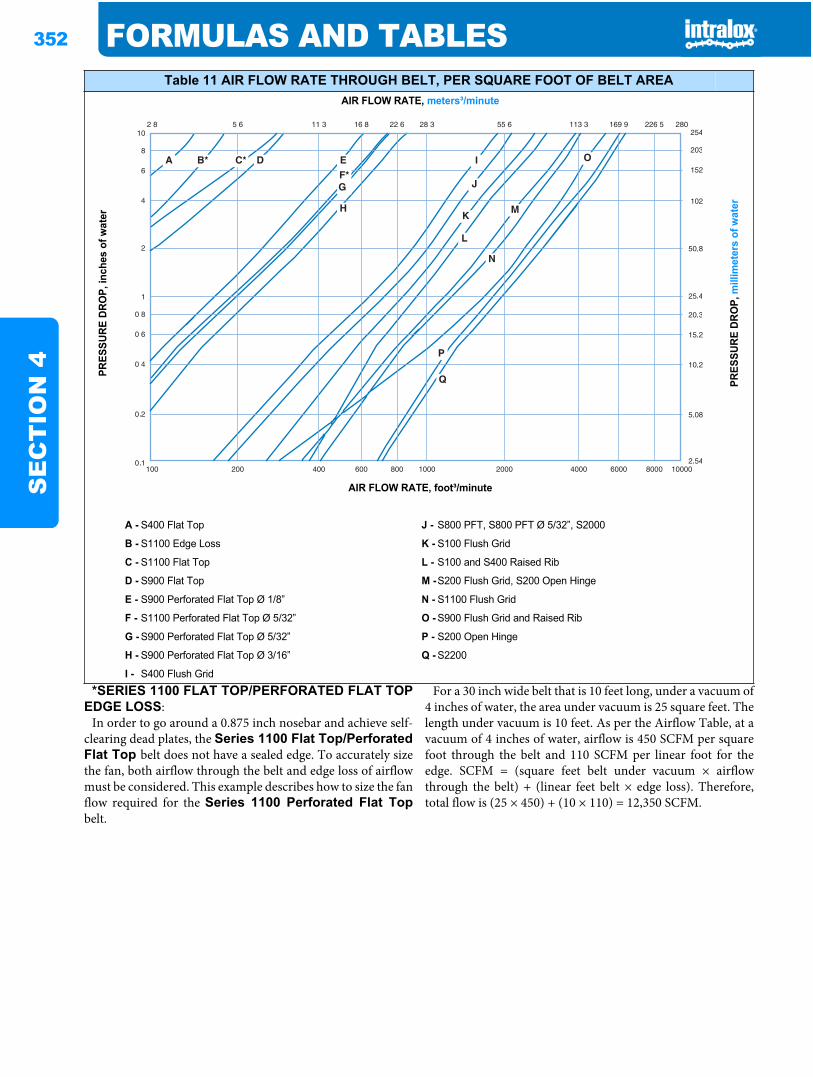
352 FORMULAS AND TABLESS
EC
TIO
N 4
*SERIES 1100 FLAT TOP/PERFORATED FLAT TOPEDGE LOSS:
In order to go around a 0.875 inch nosebar and achieve self-clearing dead plates, the Series 1100 Flat Top/PerforatedFlat Top belt does not have a sealed edge. To accurately sizethe fan, both airflow through the belt and edge loss of airflowmust be considered. This example describes how to size the fanflow required for the Series 1100 Perforated Flat Topbelt.
For a 30 inch wide belt that is 10 feet long, under a vacuum of4 inches of water, the area under vacuum is 25 square feet. Thelength under vacuum is 10 feet. As per the Airflow Table, at avacuum of 4 inches of water, airflow is 450 SCFM per squarefoot through the belt and 110 SCFM per linear foot for theedge. SCFM = (square feet belt under vacuum × airflowthrough the belt) + (linear feet belt × edge loss). Therefore,total flow is (25 × 450) + (10 × 110) = 12,350 SCFM.
Table 11 AIR FLOW RATE THROUGH BELT, PER SQUARE FOOT OF BELT AREAAIR FLOW RATE, meters³/minute
PRES
SURE
DRO
P, in
ches
of w
ater
PRES
SURE
DRO
P, m
illim
eter
s of
wat
er
AIR FLOW RATE, foot³/minute
A - S400 Flat Top J - S800 PFT, S800 PFT Ø 5/32”, S2000
B - S1100 Edge Loss K - S100 Flush Grid
C - S1100 Flat Top L - S100 and S400 Raised Rib
D - S900 Flat Top M -S200 Flush Grid, S200 Open Hinge
E - S900 Perforated Flat Top Ø 1/8” N - S1100 Flush Grid
F - S1100 Perforated Flat Top Ø 5/32” O - S900 Flush Grid and Raised Rib
G - S900 Perforated Flat Top Ø 5/32” P - S200 Open Hinge
H - S900 Perforated Flat Top Ø 3/16” Q - S2200
I - S400 Flush Grid
*
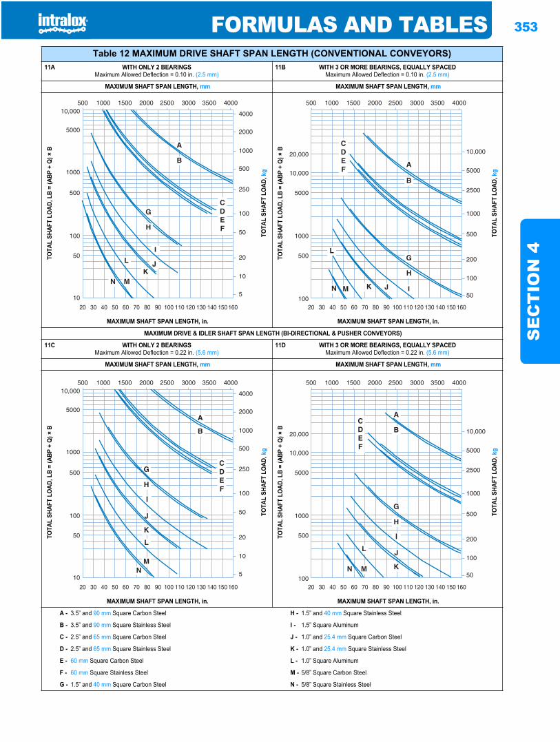
FORMULAS AND TABLES 353
SE
CT
ION
4
Table 12 MAXIMUM DRIVE SHAFT SPAN LENGTH (CONVENTIONAL CONVEYORS)11A WITH ONLY 2 BEARINGS
Maximum Allowed Deflection = 0.10 in. (2.5 mm)11B WITH 3 OR MORE BEARINGS, EQUALLY SPACED
Maximum Allowed Deflection = 0.10 in. (2.5 mm)
MAXIMUM SHAFT SPAN LENGTH, mm MAXIMUM SHAFT SPAN LENGTH, mm
TOTA
L SH
AFT
LOAD
, LB
= (A
BP +
Q) ×
B
TOTA
L SH
AFT
LOAD
, kg
TOTA
L SH
AFT
LOAD
, LB
= (A
BP +
Q) ×
B
TOTA
L SH
AFT
LOAD
, kg
MAXIMUM SHAFT SPAN LENGTH, in. MAXIMUM SHAFT SPAN LENGTH, in.
MAXIMUM DRIVE & IDLER SHAFT SPAN LENGTH (BI-DIRECTIONAL & PUSHER CONVEYORS)
11C WITH ONLY 2 BEARINGSMaximum Allowed Deflection = 0.22 in. (5.6 mm)
11D WITH 3 OR MORE BEARINGS, EQUALLY SPACEDMaximum Allowed Deflection = 0.22 in. (5.6 mm)
MAXIMUM SHAFT SPAN LENGTH, mm MAXIMUM SHAFT SPAN LENGTH, mm
TOTA
L SH
AFT
LOAD
, LB
= (A
BP +
Q) ×
B
TOTA
L SH
AFT
LOAD
, kg
TOTA
L SH
AFT
LOAD
, LB
= (A
BP +
Q) ×
B
TOTA
L SH
AFT
LOAD
, kg
MAXIMUM SHAFT SPAN LENGTH, in. MAXIMUM SHAFT SPAN LENGTH, in.
A - 3.5” and 90 mm Square Carbon Steel H - 1.5” and 40 mm Square Stainless Steel
B - 3.5” and 90 mm Square Stainless Steel I - 1.5” Square Aluminum
C - 2.5” and 65 mm Square Carbon Steel J - 1.0” and 25.4 mm Square Carbon Steel
D - 2.5” and 65 mm Square Stainless Steel K - 1.0” and 25.4 mm Square Stainless Steel
E - 60 mm Square Carbon Steel L - 1.0” Square Aluminum
F - 60 mm Square Stainless Steel M - 5/8” Square Carbon Steel
G - 1.5” and 40 mm Square Carbon Steel N - 5/8” Square Stainless Steel
20 30 40 50 60 70 80 90 100 110 120 130 140 150 160
4000
2000
1000
500
250
100
50
20
10
5
50010,000
5000
1000
500
100
50
10
1000 1500 2000 2500 3000 3500 4000
20,000
10,000
5000
1000
500
10020 30 40 50 60 70 80 90 100 110 120 130 140 150 160
10,000
5000
2500
1000
500
200
100
50
500 1000 1500 2000 2500 3000 3500 4000
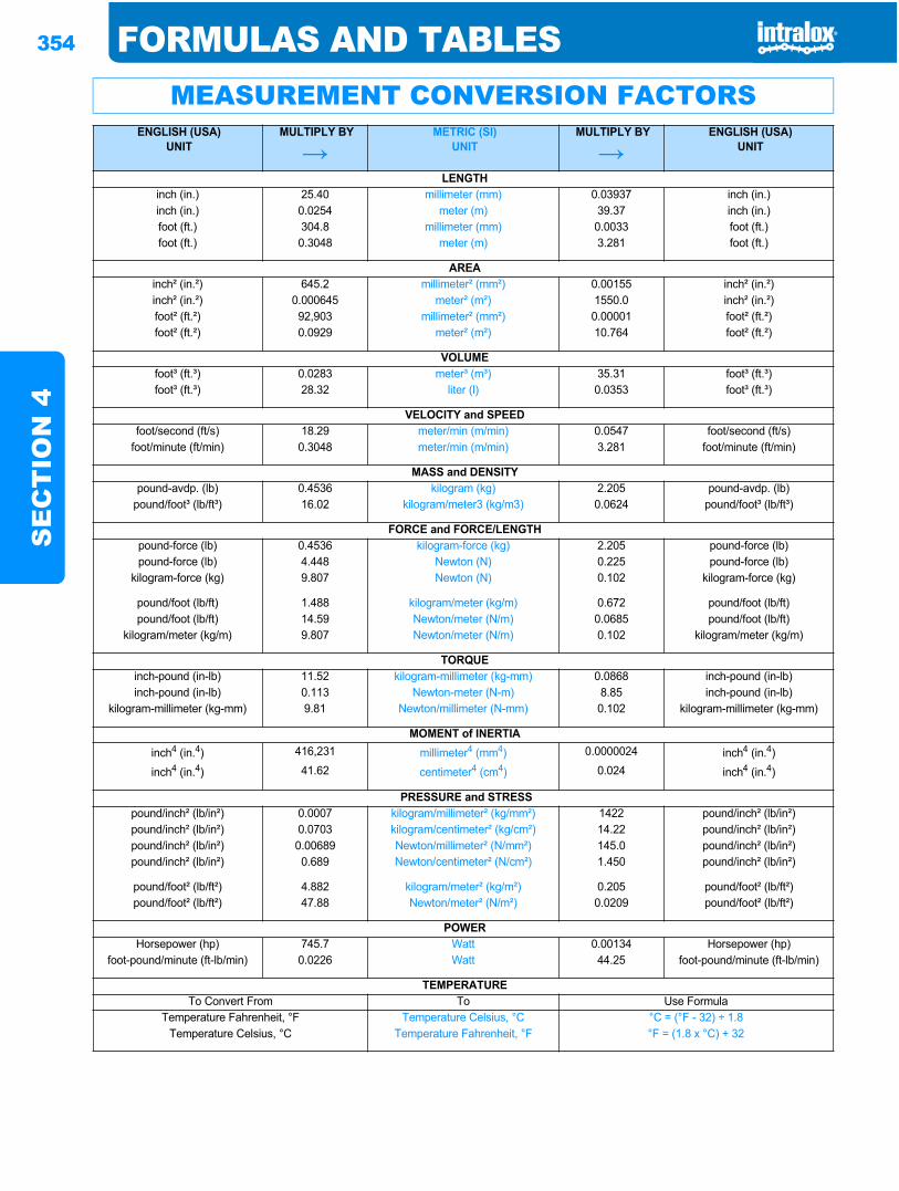
354 FORMULAS AND TABLESS
EC
TIO
N 4
MEASUREMENT CONVERSION FACTORSENGLISH (USA)
UNITMULTIPLY BY METRIC (SI)
UNITMULTIPLY BY ENGLISH (USA)
UNIT
LENGTHinch (in.) 25.40 millimeter (mm) 0.03937 inch (in.)inch (in.) 0.0254 meter (m) 39.37 inch (in.)foot (ft.) 304.8 millimeter (mm) 0.0033 foot (ft.)foot (ft.) 0.3048 meter (m) 3.281 foot (ft.)
AREAinch² (in.²) 645.2 millimeter² (mm²) 0.00155 inch² (in.²)inch² (in.²) 0.000645 meter² (m²) 1550.0 inch² (in.²)foot² (ft.²) 92,903 millimeter² (mm²) 0.00001 foot² (ft.²)foot² (ft.²) 0.0929 meter² (m²) 10.764 foot² (ft.²)
VOLUMEfoot³ (ft.³) 0.0283 meter³ (m³) 35.31 foot³ (ft.³)foot³ (ft.³) 28.32 liter (l) 0.0353 foot³ (ft.³)
VELOCITY and SPEEDfoot/second (ft/s) 18.29 meter/min (m/min) 0.0547 foot/second (ft/s)
foot/minute (ft/min) 0.3048 meter/min (m/min) 3.281 foot/minute (ft/min)
MASS and DENSITYpound-avdp. (lb) 0.4536 kilogram (kg) 2.205 pound-avdp. (lb)
pound/foot³ (lb/ft³) 16.02 kilogram/meter3 (kg/m3) 0.0624 pound/foot³ (lb/ft³)
FORCE and FORCE/LENGTHpound-force (lb) 0.4536 kilogram-force (kg) 2.205 pound-force (lb)pound-force (lb) 4.448 Newton (N) 0.225 pound-force (lb)
kilogram-force (kg) 9.807 Newton (N) 0.102 kilogram-force (kg)
pound/foot (lb/ft) 1.488 kilogram/meter (kg/m) 0.672 pound/foot (lb/ft)pound/foot (lb/ft) 14.59 Newton/meter (N/m) 0.0685 pound/foot (lb/ft)
kilogram/meter (kg/m) 9.807 Newton/meter (N/m) 0.102 kilogram/meter (kg/m)
TORQUEinch-pound (in-lb) 11.52 kilogram-millimeter (kg-mm) 0.0868 inch-pound (in-lb)inch-pound (in-lb) 0.113 Newton-meter (N-m) 8.85 inch-pound (in-lb)
kilogram-millimeter (kg-mm) 9.81 Newton/millimeter (N-mm) 0.102 kilogram-millimeter (kg-mm)
MOMENT of INERTIAinch4 (in.4) 416,231 millimeter4 (mm4) 0.0000024 inch4 (in.4)inch4 (in.4) 41.62 centimeter4 (cm4) 0.024 inch4 (in.4)
PRESSURE and STRESSpound/inch² (lb/in²) 0.0007 kilogram/millimeter² (kg/mm²) 1422 pound/inch² (lb/in²)pound/inch² (lb/in²) 0.0703 kilogram/centimeter² (kg/cm²) 14.22 pound/inch² (lb/in²)pound/inch² (lb/in²) 0.00689 Newton/millimeter² (N/mm²) 145.0 pound/inch² (lb/in²)pound/inch² (lb/in²) 0.689 Newton/centimeter² (N/cm²) 1.450 pound/inch² (lb/in²)
pound/foot² (lb/ft²) 4.882 kilogram/meter² (kg/m²) 0.205 pound/foot² (lb/ft²)pound/foot² (lb/ft²) 47.88 Newton/meter² (N/m²) 0.0209 pound/foot² (lb/ft²)
POWERHorsepower (hp) 745.7 Watt 0.00134 Horsepower (hp)
foot-pound/minute (ft-lb/min) 0.0226 Watt 44.25 foot-pound/minute (ft-lb/min)
TEMPERATURETo Convert From To Use Formula
Temperature Fahrenheit, °F Temperature Celsius, °C °C = (°F - 32) ÷ 1.8Temperature Celsius, °C Temperature Fahrenheit, °F °F = (1.8 x °C) + 32
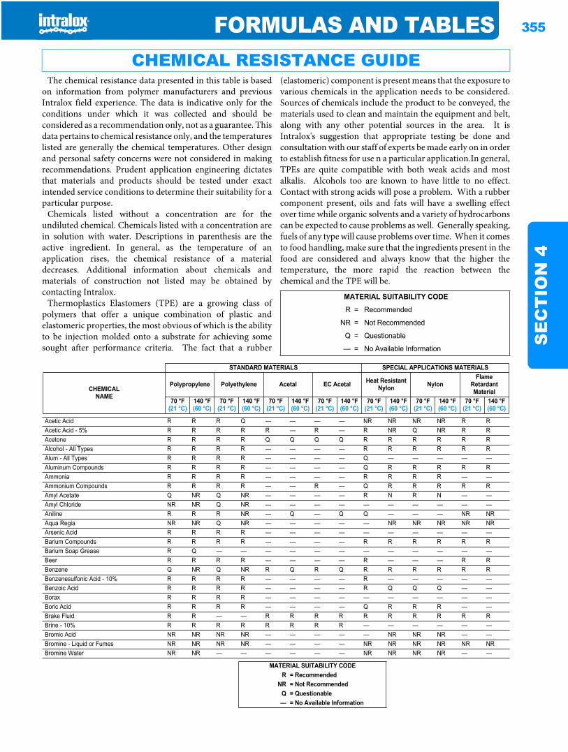
FORMULAS AND TABLES 355
SE
CT
ION
4
The chemical resistance data presented in this table is basedon information from polymer manufacturers and previousIntralox field experience. The data is indicative only for theconditions under which it was collected and should beconsidered as a recommendation only, not as a guarantee. Thisdata pertains to chemical resistance only, and the temperatureslisted are generally the chemical temperatures. Other designand personal safety concerns were not considered in makingrecommendations. Prudent application engineering dictatesthat materials and products should be tested under exactintended service conditions to determine their suitability for aparticular purpose.
Chemicals listed without a concentration are for theundiluted chemical. Chemicals listed with a concentration arein solution with water. Descriptions in parenthesis are theactive ingredient. In general, as the temperature of anapplication rises, the chemical resistance of a materialdecreases. Additional information about chemicals andmaterials of construction not listed may be obtained bycontacting Intralox.
Thermoplastics Elastomers (TPE) are a growing class ofpolymers that offer a unique combination of plastic andelastomeric properties, the most obvious of which is the abilityto be injection molded onto a substrate for achieving somesought after performance criteria. The fact that a rubber
(elastomeric) component is present means that the exposure tovarious chemicals in the application needs to be considered.Sources of chemicals include the product to be conveyed, thematerials used to clean and maintain the equipment and belt,along with any other potential sources in the area. It isIntralox's suggestion that appropriate testing be done andconsultation with our staff of experts be made early on in orderto establish fitness for use n a particular application.In general,TPEs are quite compatible with both weak acids and mostalkalis. Alcohols too are known to have little to no effect.Contact with strong acids will pose a problem. With a rubbercomponent present, oils and fats will have a swelling effectover time while organic solvents and a variety of hydrocarbonscan be expected to cause problems as well. Generally speaking,fuels of any type will cause problems over time. When it comesto food handling, make sure that the ingredients present in thefood are considered and always know that the higher thetemperature, the more rapid the reaction between thechemical and the TPE will be.
CHEMICAL RESISTANCE GUIDE
MATERIAL SUITABILITY CODE
R = Recommended
NR = Not Recommended
Q = Questionable
— = No Available Information
STANDARD MATERIALS SPECIAL APPLICATIONS MATERIALS
CHEMICALNAME
Polypropylene Polyethylene Acetal EC Acetal Heat Resistant Nylon Nylon
Flame Retardant Material
70 °F(21 °C)
140 °F(60 °C)
70 °F(21 °C)
140 °F(60 °C)
70 °F(21 °C)
140 °F(60 °C)
70 °F(21 °C)
140 °F(60 °C)
70 °F(21 °C)
140 °F(60 °C)
70 °F(21 °C)
140 °F(60 °C)
70 °F(21 °C)
140 °F(60 °C)
Acetic Acid R R R Q — — — — NR NR NR NR R RAcetic Acid - 5% R R R R R — R — R NR Q NR R RAcetone R R R R Q Q Q Q R R R R R RAlcohol - All Types R R R R — — — — R R R R R RAlum - All Types R R R R — — — — Q — — — — —Aluminum Compounds R R R R — — — — Q R R R R RAmmonia R R R R — — — — R R R R — —Ammonium Compounds R R R R — — R — Q R R R R RAmyl Acetate Q NR Q NR — — — — R N R N — —Amyl Chloride NR NR Q NR — — — — — — — — — —Aniline R R R NR — Q — Q Q — — — NR NRAqua Regia NR NR Q NR — — — — — NR NR NR NR NRArsenic Acid R R R R — — — — — — — — — —Barium Compounds R R R R — — — — R R R R R RBarium Soap Grease R Q — — — — — — — — — — — —Beer R R R R — — — — R — — — R RBenzene Q NR Q NR R Q R Q R R R R R RBenzenesulfonic Acid - 10% R R R R — — — — R — — — — —Benzoic Acid R R R R — — — — R Q Q Q — —Borax R R R R — — — — — — — — — —Boric Acid R R R R — — — — Q R R R — —Brake Fluid R R — — R R R R R R R R R RBrine - 10% R R R R R R R R — — — — — —Bromic Acid NR NR NR NR — — — — — NR NR NR — —Bromine - Liquid or Fumes NR NR NR NR — — — — NR NR NR NR NR NRBromine Water NR NR — — — — — — NR NR NR NR — —
MATERIAL SUITABILITY CODER = Recommended
NR = Not RecommendedQ = Questionable— = No Available Information
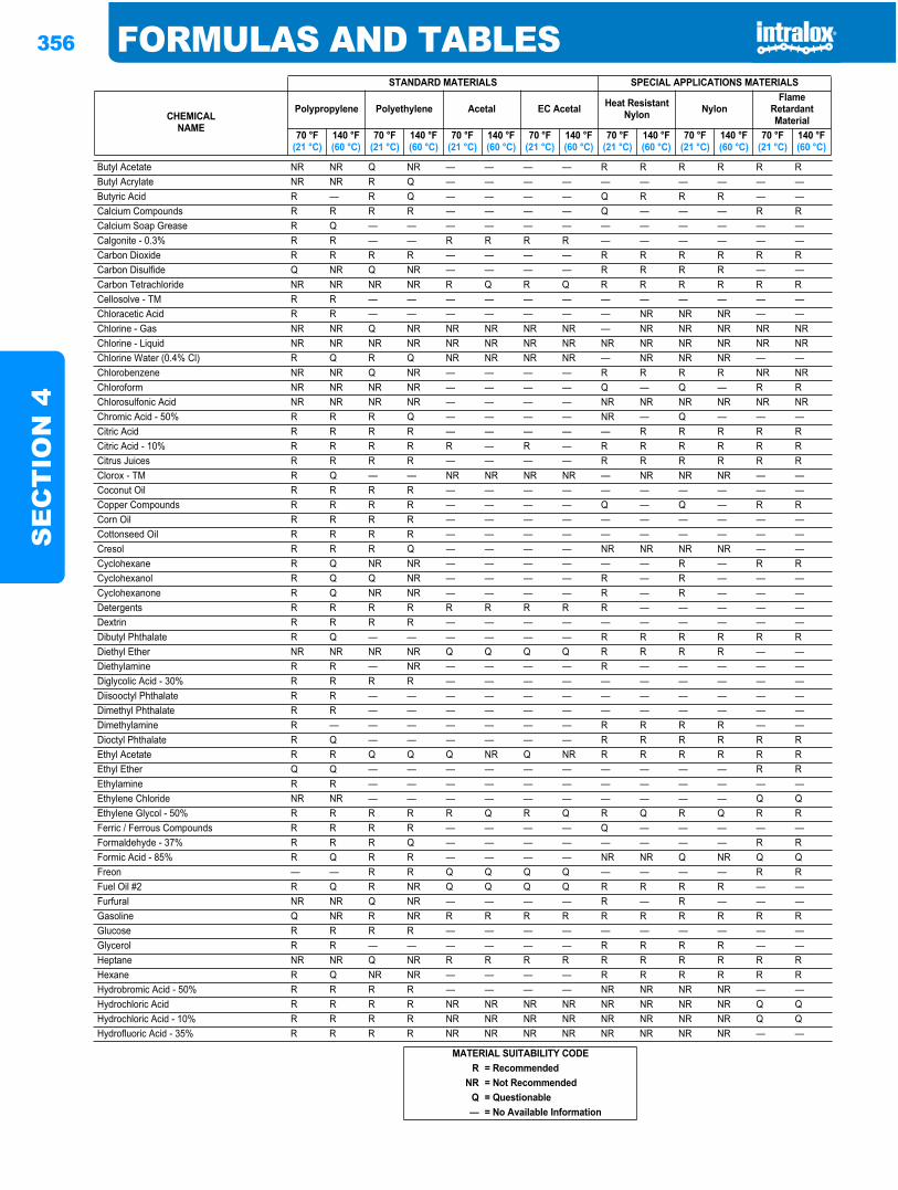
356 FORMULAS AND TABLESS
EC
TIO
N 4
Butyl Acetate NR NR Q NR — — — — R R R R R RButyl Acrylate NR NR R Q — — — — — — — — — —Butyric Acid R — R Q — — — — Q R R R — —Calcium Compounds R R R R — — — — Q — — — R RCalcium Soap Grease R Q — — — — — — — — — — — —Calgonite - 0.3% R R — — R R R R — — — — — —Carbon Dioxide R R R R — — — — R R R R R RCarbon Disulfide Q NR Q NR — — — — R R R R — —Carbon Tetrachloride NR NR NR NR R Q R Q R R R R R RCellosolve - TM R R — — — — — — — — — — — —Chloracetic Acid R R — — — — — — — NR NR NR — —Chlorine - Gas NR NR Q NR NR NR NR NR — NR NR NR NR NRChlorine - Liquid NR NR NR NR NR NR NR NR NR NR NR NR NR NRChlorine Water (0.4% Cl) R Q R Q NR NR NR NR — NR NR NR — —Chlorobenzene NR NR Q NR — — — — R R R R NR NRChloroform NR NR NR NR — — — — Q — Q — R RChlorosulfonic Acid NR NR NR NR — — — — NR NR NR NR NR NRChromic Acid - 50% R R R Q — — — — NR — Q — — —Citric Acid R R R R — — — — — R R R R RCitric Acid - 10% R R R R R — R — R R R R R RCitrus Juices R R R R — — — — R R R R R RClorox - TM R Q — — NR NR NR NR — NR NR NR — —Coconut Oil R R R R — — — — — — — — — —Copper Compounds R R R R — — — — Q — Q — R RCorn Oil R R R R — — — — — — — — — —Cottonseed Oil R R R R — — — — — — — — — —Cresol R R R Q — — — — NR NR NR NR — —Cyclohexane R Q NR NR — — — — — — R — R RCyclohexanol R Q Q NR — — — — R — R — — —Cyclohexanone R Q NR NR — — — — R — R — — —Detergents R R R R R R R R R — — — — —Dextrin R R R R — — — — — — — — — —Dibutyl Phthalate R Q — — — — — — R R R R R RDiethyl Ether NR NR NR NR Q Q Q Q R R R R — —Diethylamine R R — NR — — — — R — — — — —Diglycolic Acid - 30% R R R R — — — — — — — — — —Diisooctyl Phthalate R R — — — — — — — — — — — —Dimethyl Phthalate R R — — — — — — — — — — — —Dimethylamine R — — — — — — — R R R R — —Dioctyl Phthalate R Q — — — — — — R R R R R REthyl Acetate R R Q Q Q NR Q NR R R R R R REthyl Ether Q Q — — — — — — — — — — R REthylamine R R — — — — — — — — — — — —Ethylene Chloride NR NR — — — — — — — — — — Q QEthylene Glycol - 50% R R R R R Q R Q R Q R Q R RFerric / Ferrous Compounds R R R R — — — — Q — — — — —Formaldehyde - 37% R R R Q — — — — — — — — R RFormic Acid - 85% R Q R R — — — — NR NR Q NR Q QFreon — — R R Q Q Q Q — — — — R RFuel Oil #2 R Q R NR Q Q Q Q R R R R — —Furfural NR NR Q NR — — — — R — R — — —Gasoline Q NR R NR R R R R R R R R R RGlucose R R R R — — — — — — — — — —Glycerol R R — — — — — — R R R R — —Heptane NR NR Q NR R R R R R R R R R RHexane R Q NR NR — — — — R R R R R RHydrobromic Acid - 50% R R R R — — — — NR NR NR NR — —Hydrochloric Acid R R R R NR NR NR NR NR NR NR NR Q QHydrochloric Acid - 10% R R R R NR NR NR NR NR NR NR NR Q QHydrofluoric Acid - 35% R R R R NR NR NR NR NR NR NR NR — —
STANDARD MATERIALS SPECIAL APPLICATIONS MATERIALS
CHEMICALNAME
Polypropylene Polyethylene Acetal EC Acetal Heat Resistant Nylon Nylon
Flame Retardant Material
70 °F(21 °C)
140 °F(60 °C)
70 °F(21 °C)
140 °F(60 °C)
70 °F(21 °C)
140 °F(60 °C)
70 °F(21 °C)
140 °F(60 °C)
70 °F(21 °C)
140 °F(60 °C)
70 °F(21 °C)
140 °F(60 °C)
70 °F(21 °C)
140 °F(60 °C)
MATERIAL SUITABILITY CODER = Recommended
NR = Not RecommendedQ = Questionable— = No Available Information
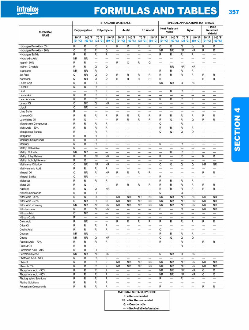
FORMULAS AND TABLES 357
SE
CT
ION
4
Hydrogen Peroxide - 3% R R R R R R R R Q Q Q Q R RHydrogen Peroxide - 90% Q Q R Q — — — — NR NR NR NR R RHydrogen Sulfide R R R R — — — — R R R R — —Hydroiodic Acid NR NR — — — — — — — — — — — —Igepal - 50% R R — — R Q R Q — — — — — —Iodine - Crystals R R Q Q — — — — — NR NR NR — —Isooctane NR NR R — — — — — R R R R — —Jet Fuel Q NR Q Q R R R R R R R R R RKerosene Q NR Q Q R R R R R — — — R RLactic Acid R R R R — — — — NR NR Q NR — —Lanolin R Q R R — — — — — — — — — —Lard — — R R — — — — — R R R — —Lauric Acid R R R R — — — — — — — — — —Lead Acetate R R R R — — — — R R R R — —Lemon Oil Q NR Q NR — — — — — — — — — —Ligroin Q NR — — — — — — — — — — — —Lime Sulfur R — — — — — — — — — — — — —Linseed Oil R R R R R R R R R R R R R RLubricating Oil R Q — — R R R R R Q R Q R RMagnesium Compounds R R R R — — — — Q — R — — —Malic Acid - 50% R R R R — — — — R R R R — —Manganese Sulfate R — R R — — — — Q Q Q Q — —Margarine R R R R — — — — — — — — — —Mercuric Compounds R R R R — — — — — — — — — —Mercury R R R R — — — — R — R — — —Methyl Cellosolve R — — — — — — — — — — — — —Methyl Chloride NR NR — — — — — — — R R R — —Methyl Ethyl Ketone R Q NR NR — — — — R — R — R RMethyl Isobutyl Ketone R Q — — — — — — — — — — — —Methylene Chloride Q NR NR NR — — — — Q Q Q Q NR NRMethylsulfuric Acid R R R R — — — — — — — — — —Mineral Oil Q NR R NR R R R R — — — — R RMineral Spirits Q NR — — — — — — R — — — — —Molasses R R R R — — — — R R R R — —Motor Oil R Q — — R R R R R R R R R RNaphtha R Q Q NR — — — — R R R R R RNickel Compounds R R R R — — — — Q — Q — — —Nitric Acid - 30% R Q R R NR NR NR NR NR NR NR NR NR NRNitric Acid - 50% Q NR R Q NR NR NR NR NR NR NR NR NR NRNitric Acid - Fuming NR NR NR NR NR NR NR NR NR NR NR NR NR NRNitrobenzene R Q NR NR — — — — Q — Q — NR NRNitrous Acid Q NR — — — — — — — — — — — —Nitrous Oxide R — — — — — — — — — — — — —Oleic Acid R NR — — R R R R R R R R R ROlive Oil R R R R — — — — — — — — — —Oxalic Acid R R R R — — — — Q — — — — —Oxygen NR NR — — — — — — R R R R — —Ozone NR NR Q NR — — — — Q Q Q Q — —Palmitic Acid - 70% R R R R — — — — R — R — R RPeanut Oil R R — — — — — — — — R — — —Perchloric Acid - 20% R R R R — — — — — — — — — —Perchlorothylene NR NR NR NR — — — — Q NR Q NR — —Phathalic Acid - 50% R R R R — — — — — — — — — —Phenol R R R R NR NR NR NR NR NR NR NR NR NRPhenol - 5% R R R R NR NR NR NR NR NR NR NR NR NRPhosphoric Acid - 30% R R R R — — — — NR NR NR NR Q QPhosphoric Acid - 85% R R R R — — — — NR NR NR NR Q QPhotographic Solutions R R R R — — — — R — R — — —Plating Solutions R R R R — — — — — — — — — —Potassium Compounds R R R R — — — — R — — — R R
STANDARD MATERIALS SPECIAL APPLICATIONS MATERIALS
CHEMICALNAME
Polypropylene Polyethylene Acetal EC Acetal Heat Resistant Nylon Nylon
Flame Retardant Material
70 °F(21 °C)
140 °F(60 °C)
70 °F(21 °C)
140 °F(60 °C)
70 °F(21 °C)
140 °F(60 °C)
70 °F(21 °C)
140 °F(60 °C)
70 °F(21 °C)
140 °F(60 °C)
70 °F(21 °C)
140 °F(60 °C)
70 °F(21 °C)
140 °F(60 °C)
MATERIAL SUITABILITY CODER = Recommended
NR = Not RecommendedQ = Questionable— = No Available Information
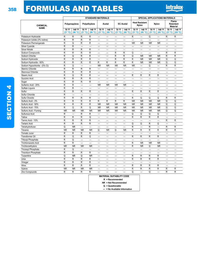
358 FORMULAS AND TABLESS
EC
TIO
N 4
Potassium Hydroxide R R R R — — — — R — Q — R RPotassium Iodide (3% Iodine) R R R R — — — — — — — — — —Potassium Permanganate R Q R R — — — — NR NR NR NR — —Silver Cyanide R R — — — — — — — — — — — —Silver Nitrate R R R R — — — — — — — — — —Sodium Compounds R R R R — — R R Q — — — R RSodium Chlorite R Q R R — — R R Q NR NR NR R RSodium Hydroxide R R R R — — R R R NR NR NR Q QSodium Hydroxide - 60% R R R R R R R R R NR NR NR Q QSodium Hypochlorite - (5% Cl) R Q — — NR NR NR NR NR — Q — R RStannic Chloride R R R R — — — — — — — — — —Stannous Chloride R R R R — — — — — — — — — —Stearic Acid R Q R R — — — — R R R R — —Succinic Acid R R R R — — — — — — — — — —Sugar R R R R — — — — — — — — — —Sulfamic Acid - 20% R R — — NR NR NR NR — — — — — —Sulfate Liquors R R — — — — — — — — — — — —Sulfur R R R R — — — — R R R R — —Sulfur Chloride R — — — — — — — — — — — — —Sulfur Dioxide R R R R — — — — R Q Q Q R RSulfuric Acid - 3% R R R R R R R R NR NR NR NR Q QSulfuric Acid - 50% R R R R NR NR NR NR NR NR NR NR Q QSulfuric Acid - 70% R Q R Q NR NR NR NR NR NR NR NR Q QSulfuric Acid - Fuming NR NR NR NR NR NR NR NR NR NR NR NR Q QSulfurous Acid R — R R — — — — Q Q Q Q — —Tallow R R R Q — — — — R R R R — —Tannic Acid - 10% R R R R — — — — — — — — R RTartaric Acid R R R R — — — — Q Q R Q — —Tetrahydrofuran Q NR — — — — — — R — R — R RToluene NR NR NR NR Q NR Q NR R R R R R RTomato Juice R R R R — — — — — — — — — —Transformer Oil R Q R Q — — — — R R R R — —Tributyl Phosphate R Q — — — — — — — — — — — —Trichloroacetic Acid R R — — — — — — R NR NR NR — —Trichloroethylene NR NR NR NR — — — — R NR Q NR — —Tricresyl Phosphate R Q — — — — — — — — — — — —Trisodium Phosphate R R R R — — — — — — — — — —Turpentine Q NR Q NR — — — — R R R R — —Urea R R R R — — — — R R R R — —Vinegar R R R R — — — — — — — — — —Wine R R R R — — — — R R R R — —Xylene NR NR NR NR — — — — R R R R R RZinc Compounds R R R R — — — — Q — Q — R R
STANDARD MATERIALS SPECIAL APPLICATIONS MATERIALS
CHEMICALNAME
Polypropylene Polyethylene Acetal EC Acetal Heat Resistant Nylon Nylon
Flame Retardant Material
70 °F(21 °C)
140 °F(60 °C)
70 °F(21 °C)
140 °F(60 °C)
70 °F(21 °C)
140 °F(60 °C)
70 °F(21 °C)
140 °F(60 °C)
70 °F(21 °C)
140 °F(60 °C)
70 °F(21 °C)
140 °F(60 °C)
70 °F(21 °C)
140 °F(60 °C)
MATERIAL SUITABILITY CODER = Recommended
NR = Not RecommendedQ = Questionable— = No Available Information
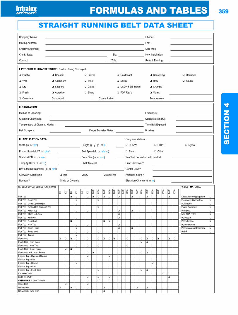
FORMULAS AND TABLES 359
SE
CT
ION
4
Formulas and tables
STRAIGHT RUNNING BELT DATA SHEETCompany Name: Phone:
Mailing Address: Fax:
Shipping Address: Dist. Mgr:
City & State: Zip: New Installation:
Contact: Title: Retrofit Existing:
I. PRODUCT CHARACTERISTICS: Product Being Conveyed
❏ Plastic ❏ Cooked ❏ Frozen ❏ Cardboard ❏ Seasoning ❏ Marinade
❏ Wet ❏ Aluminum ❏ Steel ❏ Sticky ❏ Raw ❏ Sauce
❏ Dry ❏ Slippery ❏ Glass ❏ USDA-FSIS Req’d ❏ Crumbly
❏ Fresh ❏ Abrasive ❏ Sharp ❏ FDA Req’d ❏ Other:
❏ Corrosive: Compound Concentration Temperature
II. SANITATION:
Method of Cleaning: Frequency:
Cleaning Chemicals: Concentration (%):
Temperature of Cleaning Media: Time Belt Exposed:
Belt Scrapers: Finger Transfer Plates: Brushes:
III. APPLICATION DATA: Carryway Material:
Width (in. or mm) Length CL -CL (ft. or m) ❏ UHMW ❏ HDPE ❏ Nylon
Product Load (lb/ft² or kg/m²) Belt Speed (ft. or m/min.) ❏ Steel ❏ Other
Sprocket PD (in. or mm) Bore Size (in. or mm) % of belt backed-up with product
Temp @ Drive (°F or °C) Shaft Material Push Conveyor?
Drive Journal Diameter (in. or mm) Center Drive?
Carryway Conditions: ❏ Wet ❏ Dry ❏ Abrasive Frequent Starts?
Nosebar? Static or Dynamic Elevation Change (ft. or m)
IV. BELT STYLE: SERIES (Check One) V. BELT MATERIAL
100
200
400
800
850
900
1000
1100
1200
1400
1500
1600
1650
1700
1800
1900
2200
2400
2600
2700
3000
4000
9000
Flat Top ❏ ❏ ❏ ❏ ❏ ❏ ❏ ❏ ❏ ❏ ❏ Detectable Polypropylene ❏
Flat Top - Cone Top ❏ ❏ Electrically Conductive ❏
Flat Top - Cone Open Hinge ❏ FDA Nylon ❏
Flat Top - Embedded Diamond Top ❏ Flame Retardant ❏
Flat Top - Mesh Top ❏ ❏ ❏ ❏ Hi-Impact ❏
Flat Top - Mesh Nub Top ❏ Non-FDA Nylon ❏
Flat Top - Mini-Rib ❏ ❏ Polyacetal ❏
Flat Top - Non-Skid ❏ ❏ ❏ Polyethylene ❏
Flat Top - Nub Top ❏ ❏ ❏ Polypropylene ❏
Flat Top - Open Hinge ❏ ❏ ❏ Polypropylene Composite ❏
Flat Top - Perforated ❏ ❏ ❏ PVDF ❏
Flat Top - Tough ❏
Flush Grid ❏ ❏ ❏ ❏ ❏ ❏ ❏ ❏ ❏ ❏ ❏ ❏ ❏ ❏ ❏ ❏
Flush Grid - High Deck ❏ ❏
Flush Grid - Nub Top ❏ ❏ ❏ ❏
Flush Grid - Open Hinge ❏ ❏
Flush Grid with Insert Rollers ❏ ❏ ❏ ❏
Friction Top - Diamond/Square ❏ ❏
Friction Top - Flat ❏ ❏
Friction Top - Round ❏ ❏
Friction Top - Oval ❏
Friction Top - Flush Grid ❏ ❏ ❏
Knuckle Chain ❏
Mold-To-Width ❏ ❏ ❏ ❏
ONEPIECE™ Live Transfer ❏ ❏ ❏
Open Grid ❏ ❏
Raised Rib ❏ ❏ ❏ ❏ ❏ ❏ ❏
Raised Rib - Non-Skid ❏
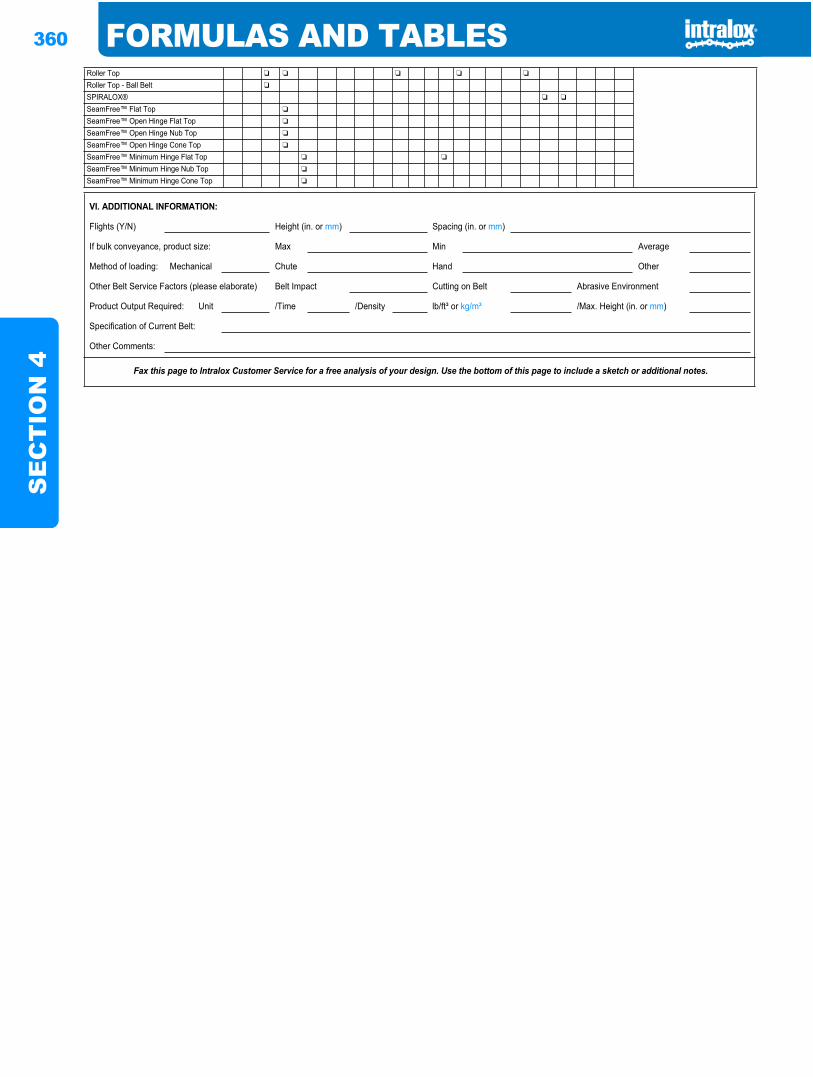
360 FORMULAS AND TABLESS
EC
TIO
N 4
Roller Top ❏ ❏ ❏ ❏ ❏
Roller Top - Ball Belt ❏
SPIRALOX® ❏ ❏
SeamFree™ Flat Top ❏
SeamFree™ Open Hinge Flat Top ❏
SeamFree™ Open Hinge Nub Top ❏
SeamFree™ Open Hinge Cone Top ❏
SeamFree™ Minimum Hinge Flat Top ❏ ❏
SeamFree™ Minimum Hinge Nub Top ❏
SeamFree™ Minimum Hinge Cone Top ❏
VI. ADDITIONAL INFORMATION:
Flights (Y/N) Height (in. or mm) Spacing (in. or mm)
If bulk conveyance, product size: Max Min Average
Method of loading: Mechanical Chute Hand Other
Other Belt Service Factors (please elaborate) Belt Impact Cutting on Belt Abrasive Environment
Product Output Required: Unit /Time /Density lb/ft³ or kg/m³ /Max. Height (in. or mm)
Specification of Current Belt:
Other Comments:
Fax this page to Intralox Customer Service for a free analysis of your design. Use the bottom of this page to include a sketch or additional notes.
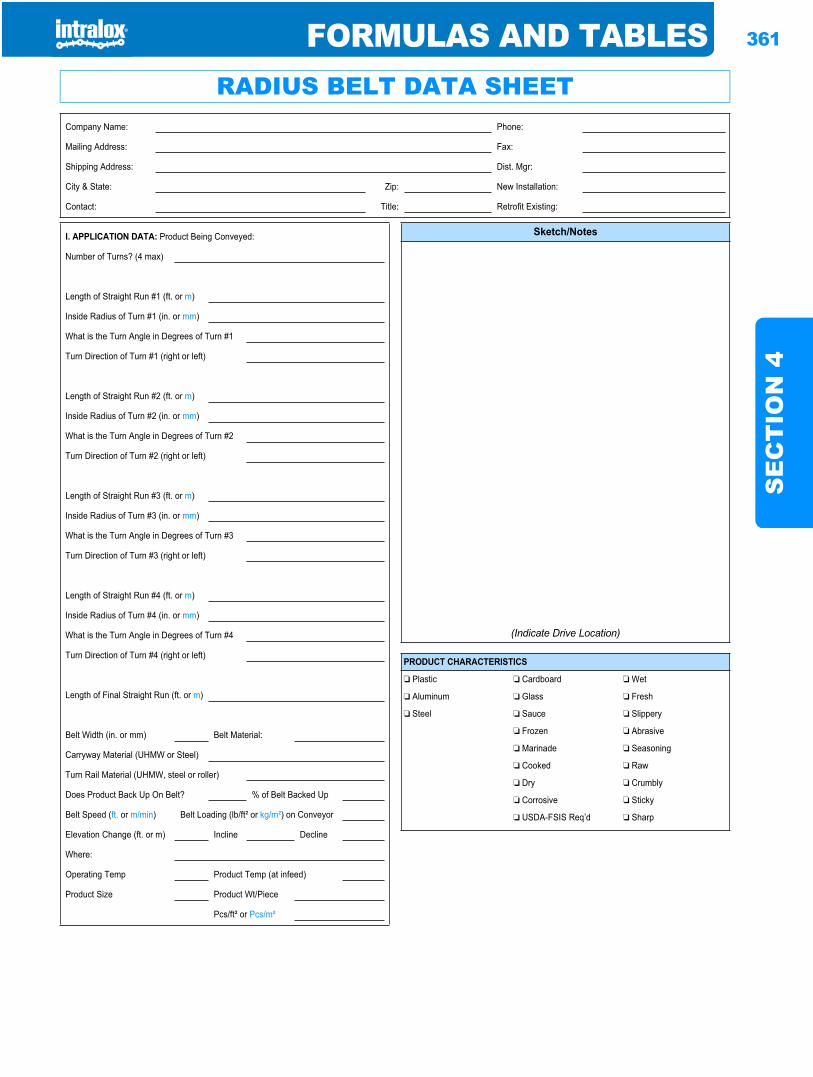
FORMULAS AND TABLES 361
SE
CT
ION
4
Formulas and tables
RADIUS BELT DATA SHEETCompany Name: Phone:
Mailing Address: Fax:
Shipping Address: Dist. Mgr:
City & State: Zip: New Installation:
Contact: Title: Retrofit Existing:
I. APPLICATION DATA: Product Being Conveyed:
Number of Turns? (4 max)
Length of Straight Run #1 (ft. or m)
Inside Radius of Turn #1 (in. or mm)
What is the Turn Angle in Degrees of Turn #1
Turn Direction of Turn #1 (right or left)
Length of Straight Run #2 (ft. or m)
Inside Radius of Turn #2 (in. or mm)
What is the Turn Angle in Degrees of Turn #2
Turn Direction of Turn #2 (right or left)
Length of Straight Run #3 (ft. or m)
Inside Radius of Turn #3 (in. or mm)
What is the Turn Angle in Degrees of Turn #3
Turn Direction of Turn #3 (right or left)
Length of Straight Run #4 (ft. or m)
Inside Radius of Turn #4 (in. or mm)
What is the Turn Angle in Degrees of Turn #4
Turn Direction of Turn #4 (right or left)
Length of Final Straight Run (ft. or m)
Belt Width (in. or mm) Belt Material:
Carryway Material (UHMW or Steel)
Turn Rail Material (UHMW, steel or roller)
Does Product Back Up On Belt? % of Belt Backed Up
Belt Speed (ft. or m/min) Belt Loading (lb/ft² or kg/m²) on Conveyor
Elevation Change (ft. or m) Incline Decline
Where:
Operating Temp Product Temp (at infeed)
Product Size Product Wt/Piece
Pcs/ft² or Pcs/m²
Sketch/Notes
(Indicate Drive Location)
PRODUCT CHARACTERISTICS
❏ Plastic ❏ Cardboard ❏ Wet
❏ Aluminum ❏ Glass ❏ Fresh
❏ Steel ❏ Sauce ❏ Slippery
❏ Frozen ❏ Abrasive
❏ Marinade ❏ Seasoning
❏ Cooked ❏ Raw
❏ Dry ❏ Crumbly
❏ Corrosive ❏ Sticky
❏ USDA-FSIS Req’d ❏ Sharp

362 FORMULAS AND TABLESS
EC
TIO
N 4
II. SANITATION:
Method of Cleaning: Frequency:
Cleaning Chemicals: Concentration (%):
Temperature of Cleaning Media: Time Belt Exposed:
Belt Scrapers: Finger Transfer Plates: Brushes:
Fax this page to Intralox Customer Service for a free analysis of your design using Series 2200 Radius Belt, Series 2400, Series 2600, Series 2700, Series 3000 Turning, and Series 4000 belts.

FORMULAS AND TABLES 363
SE
CT
ION
4
Formulas and tables
SPIRAL BELT DATA SHEETCompany Name: Phone:
Mailing Address: Fax:
Shipping Address: Dist. Mgr:
City & State: Zip: New Installation:
Contact: Title: Retrofit Existing:
I. APPLICATION DATA: Product Being Conveyed:
Purpose of Spiral:
Product:
Spiral Temperature:
Belt Width (in. or mm):
Actual Cage Radius (in. or mm) from Spiral to Inside of Belt Edge:
Tier Spacing (in. or mm):
Number of Tiers:
Additional Belt Length (including all belt not driven by spiral cage, i.e., infeed length, discharge length, and length through the overdrive and take-up systems) (ft. or m):
Belt Speed (ft/min or m/min):
Product Weight (lb/ft² or kg/m² on belt):
PRODUCT CHARACTERISTICS
❏Dry ❏Wet
❏Frozen ❏Fresh
❏Sauce ❏Slippery
❏Breaded ❏Abrasive
❏Battered
❏Marinade ❏Seasoning
❏Cooked ❏Raw
❏Crumbly
❏Corrosive ❏Sticky
❏USDA-FSIS Req’d ❏Sharp
II. SPIRAL DATA:
Spiral System Manufacturer:
Is Spiral Up or Down: Current Belt Employed:
Wearstrip Material: Method of Loading Belt:
Spacing of Carryway Wearstrips:
Number of Wearstrips:
Cage Bar Surface Material (UHMW, Steel, etc.): Cage Bar Width: Spacing:
Clearance Between Wearstrip Surface and the Bottom of the Next Tier Wearstrip Support:
Does Belt Turn Right or Left onto Spiral Cage:
Gravity Take-up Weight: Gravity Take-up Movement/Stroke:
Overdrive Speed Control Type (Mechanical, Electrical):
Overdrive Shaft Size: Journal Diameter:
Idler Roller Diameters: Size:
Overdrive Type (Drives on Top or Bottom of Belt):
Type of Return Rail for Spiral Radius Belt Return (bull wheel, UHMW guide, rollers, etc.):
II. SANITATION:
Method of Cleaning: Frequency:
Cleaning Chemicals: Concentration (%):
Temperature of Cleaning Media: Time Belt Exposed (Temp):
Belt Scrapers: Finger Transfer Plates: Brushes:
Fax this page to Intralox Customer Service for a free analysis of your design.

364 FORMULAS AND TABLESS
EC
TIO
N 4
GLOSSARY 365
GLO
SS
AR
Y
GLOSSARYAACCUMULATION TABLES: Conveyors that absorbtemporary product overflows due to fluctuations indownstream operations. They may be uni-directional or bi-directional.
ACETAL: A thermoplastic that is strong, has a good balanceof mechanical and chemical properties, and has good fatigueendurance and resilience. It has a low coefficient of friction.Temperature range is from-50 °F (-45 °C) to +200 °F (93 °C).Its specific gravity is approximately 1.40.
ADJUSTED BELT PULL: The belt pull adjusted for ServiceFactors.
ALLOWABLE BELT STRENGTH: The rated belt strengthadjusted for Temperature and Strength Factors.
BBELT PITCH: center distance between hinge rods in anassembled belt.
BELT PULL: The tensile load on a belt after the productloading, belt weight, conveyor length, total friction factor andelevation change is applied.
BRICKLAYED: Belt construction where plastic modules arestaggered with those in adjacent rows.
CCATENARY SAG: A belt or chain hanging under theinfluence of gravity between two (2) supports will assume theshape of a curve called a “catenary”.
CENTER-DRIVEN BELTS: Belts driven by the sprocket ata point midway between the hinge rods.
CHEVRON CARRYWAYS: Support rails which are placedin an overlapping “V” pattern. This array supports theconveyor belt across the full width while distributing the wearmore evenly. This pattern is very effective when moderateabrasion is present, providing a self cleaning method.
CHORDAL ACTION: The pivoting action of the belt’smodules about their hinge rods as the modules engage anddisengage the sprocket. This results in a pulsation in the belt’sspeed, and a rise and fall in the belt’s surface.
COEFFICIENTS OF FRICTION: A ratio of frictional forceto contact force, which is determined experimentally.Coefficients of friction are usually stated for both dry andlubricated surfaces, and for start-up and running conditions.
DDEAD PLATE GAP: Gap or clearance between the surfaceof a conveyor belt and any other surface onto which productsor containers being conveyed are to be transferred.
DEFLECTION: Displacement or deformation due toloading.
EELEVATING CONVEYORS: These conveyors have severaltypes of variations and are employed when product elevationis necessary. Elevators almost always employ flights andsideguards, which present special consideration in the design.
EXTRA-WIDE SPROCKETS: Available only in a Series200, hinge-driven, diameter sprocket. Provides an extra-wide(double) driving area.
FF.D.A.: Food and Drug Administration. Federal agencywhich regulates materials that may come in contact with foodproducts.
FINGER TRANSFER PLATES: Comb-like plates that areemployed with Intralox Raised Rib belts to minimize problemswith product transfer and tipping.
FLAT PLATE CARRYWAYS: These are continuoussheets, usually of metal, over which the belt slides.
FLAT TOP STYLE: Modular plastic belt with a smooth,closed surface.
FLIGHTS: A vertical surface across the width of the belt. Anintegral part of the Intralox belt, employed where elevation ofproduct is required (e.g., Incline Conveyors, ElevatorConveyors).
FLUID COUPLINGS: A device which allows the drivenconveyor to accelerate gradually to operating speeds. Fluidcouplings are recommended when frequent starts and stops ofhigh speed or heavily loaded conveyors occur, and they alsoserve as an overload safety.
FLUSH GRID STYLE: Modular plastic belt with a smooth,open grid.
FRICTION: The force which acts between two bodies at theirsurface of contact, so as to resist their sliding on each other (seeCoefficients of Friction).
GGRAVITY TAKE-UP: Usually consists of a roller resting onthe belt in the returnway, its weight providing the tensionneeded to maintain proper sprocket engagement. It is most
366 GLOSSARYG
LOS
SA
RY
effective when placed near the drive shaft end of thereturnway.
HH.D.P.E.: High Density Polyethylene resin used in themanufacture of wearstrip. Employed, where abrasion is not aproblem, to reduce friction between belt and the carrywaysurface.
HINGE RODS: Plastic rods that are used in the assembly ofmodular plastic belts. They also serve as the hinges aroundwhich the belt modules rotate.
HINGE-DRIVEN BELTS: Belts driven at the hinges by thesprocket.
HORSEPOWER:
English (USA) Units — The power delivered by amachine while doing work at the rate of 550 foot pounds persecond (ft-lb/sec), or 33,000 foot pounds per minute (ft-lb/min). The watt and kilowatt are power units used in ratingelectrical equipment. One kilowatt is equal to 1,000 watts. Onehorsepower equals 746 watts or 0.746 kilowatts. One kilowatt(kW) is equal to 1.341 horsepower.
Metric Units — The power delivered by a machine whiledoing work at the rate of 75 kilogram-meters per second (kg-m/sec), or 4500 kilogram-meters per minute (kg-m/min). Onekilowatt (kW) is equal to 1.359 metric horsepower. One metrichorsepower equals 736 watts or 0.736 kilowatts and closelyapproximates one English (USA) Horsepower, 746 watts.
Where calculations in this manual are done in metric units,power calculations are computed in Watts. WhereverHorsepower (HP) is used, it refers to the English (USA) value.
IIDLER ROLLERS: Steel or plastic pipes that are supportedby stub shafts used in place of idle shafts and sprockets. Thesepipe rollers may be considerably stiffer than a length of solidsquare shaft of comparable weight.
INERTIA: The tendency of a body to remain at rest or to stayin motion, unless acted upon by an outside force.
INTERMEDIATE BEARINGS: An additional bearing (orbearings) located near the center of a shaft to reduce shaftdeflection to an acceptable level.
KKNUCKLE CHAIN: : Narrow chain with relatively highstrength that is commonly used in multiple strandapplications. Knuckle Chain typically handles boxes, totes,pans or other large products.
LLOAD-BEARING ROLLERS: Steel or plastic pipessupported by stub shafts which provide stiffness. Employed oncenter-drive Accumulation Conveyors on either side of thedrive shaft.
MMODULAR CONSTRUCTION: Injection-molded plasticmodules assembled into an interlocked unit and joinedtogether by hinge rods.
MODULE PITCH: The distance between the rod holecenterlines on a module.
MODULES: Injection-molded plastic parts used in theassembly of an Intralox belt.
MOLYBDENUM-FILLED NYLON (NYLATRON): A typeof wearstrip plastic.
MOMENT OF INERTIA: A characteristic of the shape of anobject which describes its resistance to bending or twisting.
NNYLATRON: (see Molybdenum-filled Nylon).
OONEPIECE™ LIVE TRANSFER BELT: Modular plasticbelt with an integral transfer edge for smooth, self-clearing,right angle transfers onto takeaway belts.
OPEN AREA: The percentage of area in the plane of theplastic belt that is unobstructed by plastic.
OPEN GRID STYLE: Modular plastic belt with low profile,transverse ribs.
OPEN HINGE STYLE: Modular plastic belt with exposedhinge rods and a flush surface.
OUTSIDE DIAMETER: The distance from the top of asprocket tooth to the top of the opposite tooth, measuredthrough the centerline of the sprocket.
PPARALLEL CARRYWAYS: Belt support rails that may beeither metal or plastic, placed on the conveyor frame parallel tothe belt’s travel.
PERFORATED FLAT TOP STYLE: Modular plastic beltwith a smooth, perforated top.
PITCH: (see Belt Pitch or Module Pitch).
GLOSSARY 367
GLO
SS
AR
Y
PITCH DIAMETER: Diameter of a circle, which passesthrough the centerlines of hinge rods, when the belt is wrappedaround a sprocket.
POLYACETAL: (see Acetal).
POLYETHYLENE: A lightweight thermoplastic, buoyant inwater, with a specific gravity of 0.95. It is characterized bysuperior fatigue resistance, flexibility and high-impactstrength. Exhibits excellent performance at low temperatures,-100 °F (-73 °C). Upper continuous temperature limit is+150 °F (+66 °C).
POLYPROPYLENE: A thermoplastic material thatprovides good chemical resistance characteristics.Polypropylene is buoyant in water, with a specific gravity ofapproximately 0.90. It is suitable for continuous service intemperatures from +34 °F (+1 °C) to +220 °F (+104 °C).
PULL-PULL BI-DIRECTIONAL CONVEYORS: Thereare three common variations of the Pull-pull type of reversing(bi-directional) conveyors: the center-Drive method, the Two-Motor drive method, and the Single-Motor/Slave-Drivemethod.
PUSHER BAR: A device used on bi-directionalaccumulation tables (i.e., in the bottling and canningindustries) which allows the table to be filled to its capacity andassists in an orderly and complete discharge from the tableback onto the conveying line.
PUSH-PULL BI-DIRECTIONAL CONVEYORS: A conveyor employing one motor that will be reversing (bi-
directional). In one direction the belt is being pulled and in thereversing direction the belt is being pushed.
RRAISED RIB STYLE: Modular plastic belt with a highprofile, longitudinally ribbed surface.
RETAINER RINGS: A shaft and sprocket accessory whichrestricts the lateral movement of the sprocket with respect tothe shaft.
RETURNWAYS: The path the belt follows toward the idlershaft and sprockets.
RODS: (see Hinge Rods).
ROLLER CARRYWAYS: Carryway surface that does notprovide a continuous running surface. The chordal action, asthe modules pass over the rollers, may cause problems ifproduct tippage is critical.
SSCREW TAKE-UP: These types of take-ups shift theposition of one of the shafts, usually the idler, through the useof adjustable machine screws.
SCROLL: Device used in place of the idle shaft and sprocketsto prevent debris from accumulating on the inside of theconveyor belt. Scrolls are fabricated by welding steel left handpitch and right hand pitch helical ribs to a common roundshaft.
SERVICE FACTORS: Driven machines and power sourcesmay be classified by severity factors, which reflect the type ofservice placed upon the power transmission components.High service factors are assigned to more severe applications,thereby providing sufficient component strength to render anacceptable life expectancy for that component. Additionalservice factors may be required for continuous serviceapplications requiring braking (e.g., starts/stops) or reversingaction (e.g., bidirectional accumulation tables). Service factorshelp to insure optimal service life of the components.
SIDEGUARDS: Intralox belt accessory which forms avertical wall near the belt edge and is an integral part of thebelt.
SINGLE-MOTOR/SLAVE-DRIVE: Employing one motor(reversible) using a roller chain, alternately driving either oftwo chain sprockets on the conveyor shaft. This drive system isusually limited to short conveyors because of the length ofroller chain involved.
SOFT START MOTORS: When rapid starts and stops ofhigh speed and loaded conveyors occur, these devices arerecommended. They allow the driven conveyor to accelerategradually to operating speeds, which is beneficial for allconveyor components.
SPECIFIC GRAVITY: A dimensionless ratio of the densityof a substance to the density of water.
STATIC ELECTRICITY: An electrical charge build-up on asurface as a result of rolling or sliding contact with anothersurface.
TTAKE-UP UNITS: (see Gravity or Screw Take-Up).
THERMAL EXPANSION/CONTRACTION: With fewexceptions, the dimensions of all substances increase as theirtemperature is increased and contract as their
temperature is decreased. Plastics expand and contract rathersignificantly.
TORQUE: The capability or tendency of a force forproducing torsion or rotation about an axis. For example, thetwisting action on a turning shaft.
TWO-MOTOR DRIVE DESIGN: In this design, the belt isalternately pulled in either direction (e.g., bi-directionalaccumulation tables). Returnway belt tension is relatively low,requires rather expensive additional hardware (e.g., anadditional motor), slip clutches and electrical controlcomponents.

368 GLOSSARYG
LOS
SA
RY
UU.H.M.W.: Ultra High Molecular Weight, polyethylene resinused in the manufacture of wear-strip. It has very good wearcharacteristics, impact resistance and has an excellentcombination of physical and mechanical.
U.S.D.A.-F.S.I.S.: United States Department of Agriculture.Federal agency which regulates equipment that may beemployed in Meat, Dairy and Poultry facilities.
WWEARSTRIP: Plastic strips that are added to a conveyorframe to increase the useful life of the frame and the conveyorbelting. Also helpful in reducing sliding friction forces.
INDEX 369
IND
EX
INDEX
AAbrasion Resistance System . . . . . . . . . . . . . . . . . . . . . . . . .316Abrasion Resistant (AR) Nylon . . . . . . . . . . . . . . . . . . . . . . . .18Accumulation Tables . . . . . . . . . . . . . . . . . . . . . . . . . . . . . . .365Acetal . . . . . . . . . . . . . . . . . . . . . . . . . . . . . . . . . . . . . . 18, 32, 365
Electrically Conductive (EC) . . . . . . . . . . . . . . . . . . . . . .19Adjusted Belt Pull . . . . . . . . . . . . . . . . . . . . . . . . . . . . . . . . . .365Allowable Belt Strength . . . . . . . . . . . . . . . . . . . . . . . . . 36, 365Ambient Conditions . . . . . . . . . . . . . . . . . . . . . . . . . . . . . . . .322Analysis for sideflexing belts . . . . . . . . . . . . . . . . . . . . . . . . . .15Analysis for straight running belts . . . . . . . . . . . . . . . . . . . . .15Angle and clip-on wearstrips . . . . . . . . . . . . . . . . . . . . . . . . .321Anti-Sag Carryway Wearstrip Configuration . . . . . . . . . . .322
BBack Tension . . . . . . . . . . . . . . . . . . . . . . . . . . . . . . . . . . . . . .323Basic Conveyor Frame Requirements . . . . . . . . . . . . . . . . .317Bearing Journals (see Shaft) . . . . . . . . . . . . . . . . . . . . . . . . . .303Belt
Carryways . . . . . . . . . . . . . . . . . . . . . . . . . . . . . . . . . . . . .320Construction . . . . . . . . . . . . . . . . . . . . . . . . . . . . . . . . . . . .4Selection . . . . . . . . . . . . . . . . . . . . . . . . . . . . . . . . . . . . . . .36Style
Flat Top . . . . . . . . . . . . . . . . . . . . . . . . . . . . . . . . . . . . .7Flush Grid . . . . . . . . . . . . . . . . . . . . . . . . . . . . . . . . . . .6Friction Top . . . . . . . . . . . . . . . . . . . . . . . . . . . . . . . . .9Knuckle Chain . . . . . . . . . . . . . . . . . . . . . . . . . . . . . .14Mould To Width . . . . . . . . . . . . . . . . . . . . . . . . . . . .13Open Grid . . . . . . . . . . . . . . . . . . . . . . . . . . . . . . . . . .11Perforated Flat Top . . . . . . . . . . . . . . . . . . . . . . . . . . .8Raised Rib . . . . . . . . . . . . . . . . . . . . . . . . . . . . . . . . . . .8Roller Top . . . . . . . . . . . . . . . . . . . . . . . . . . . . . . . . . .11Textured Flat Top . . . . . . . . . . . . . . . . . . . . . . . . . . .10
Weight . . . . . . . . . . . . . . . . . . . . . . . . . . . . . . . . . . . . . . . .311Belt Accessories . . . . . . . . . . . . . . . . . . . . . . . . . . . . . . . . . . . . .17Belt Carryways . . . . . . . . . . . . . . . . . . . . . . . . . . . . . . . . . . . . .320Belt Data . . . . . . . . . . . . . . . . . . . . . . . . . . . . . . . . . . . . . . . . . . .17Belt Material Properties . . . . . . . . . . . . . . . . . . . . . . . . . . . . . .21Belt Pitch . . . . . . . . . . . . . . . . . . . . . . . . . . . . . . . . . . . . . . . . . .365Belt Pull . . . . . . . . . . . . . . . . . . . . . . . . . . . . . . . . . . . . . . . . . . .365Belt Selection Instructions . . . . . . . . . . . . . . . . . . . . . . . . . . . .36Belt Selection Process . . . . . . . . . . . . . . . . . . . . . . . . . . . . . . . . .5Belt Style And Material Availability . . . . . . . . . . . . . . . . . . . .22Belt Surface Wear . . . . . . . . . . . . . . . . . . . . . . . . . . . . . . . . . . .15Bi-Directional Conveyors . . . . . . . . . . . . . . . . . . . . . . . . . . .326Bricklayed . . . . . . . . . . . . . . . . . . . . . . . . . . . . . . . . . . . . . . . . .365
CCarryway (see Wearstrip)
Anti-Sag Carryway Wearstrip Configurations . . . . . .322Solid Plate . . . . . . . . . . . . . . . . . . . . . . . . . . . . . . . . . . . . .321Wearstrip . . . . . . . . . . . . . . . . . . . . . . . . 310, 311, 321, 322
Catenary . . . . . . . . . . . . . . . . . . . . . . . . . . . . . . . . . . . . . . . . . .329Catenary Sag . . . . . . . . . . . . . . . . . . . . . . . . . . . . . . . . . . 323, 365Center-driven Belts . . . . . . . . . . . . . . . . . . . . . . . . . . . . . . . . .365Chemical Resistance . . . . . . . . . . . . . . . . . . . . . . . . . . . . . . . .322
Chevron Array . . . . . . . . . . . . . . . . . . . . . . . . . . . . . . . . . . . . 321Chevron Carryways . . . . . . . . . . . . . . . . . . . . . . . . . . . . . . . . 365Chordal Action . . . . . . . . . . . . . . . . . . . . . . . . . . . . . . . . . 15, 365Coefficient of Friction . . . . . . . . . . . . . . . . . . . . . . . . . . . . . . 36590° Container Transfers . . . . . . . . . . . . . . . . . . . . . . . . . . . . . 335Control of Belt Length . . . . . . . . . . . . . . . . . . . . . . . . . . . . . . 322Conveyor design issues for friction modules . . . . . . . . . . . 332Conveyors, Special . . . . . . . . . . . . . . . . . . . . . . . . . . . . . . . . . . 32
Bi-directional . . . . . . . . . . . . . . . . . . . . . . . . . . . . . . . . . . 326Pull-Pull, Center-Drive . . . . . . . . . . . . . . . . . . . . . 326Pull-Pull, Single-Motor and Slave-Drive . . . . . . . 326Pull-Pull, Two-Motor Drive . . . . . . . . . . . . . . . . . 326
Elevating . . . . . . . . . . . . . . . . . . . . . . . . . . . . . . . . . . . . . . 328Custom Wearstrips . . . . . . . . . . . . . . . . . . . . . . . . . . . . . . . . 310
DDead Plate Gap . . . . . . . . . . . . . . . . . . . . . . . . . . . . . . . . . . . . 365Dead Plates . . . . . . . . . . . . . . . . . . . . . . . . . . . . . . .311, 312, 334Deflection . . . . . . . . . . . . . . . . . . . . . . . . . . . . . . . . . . . . . . . . 365Design Requirements . . . . . . . . . . . . . . . . . . . . . . . . . . . . . . . . . 5Detectable Polypropylene . . . . . . . . . . . . . . . . . . . . . . . . . . . . 18Diamond Friction Top . . . . . . . . . . . . . . . . . . . . . . . . . . . . . . 126Diamond Friction Top Ultra . . . . . . . . . . . . . . . . . . . . . . . . 126Dimension Definitions . . . . . . . . . . . . . . . . . . . . . . . . . . . . . 318Drive Guidelines . . . . . . . . . . . . . . . . . . . . . . . . . . . . . . . . . . . 318Drive Method . . . . . . . . . . . . . . . . . . . . . . . . . . . . . . . . . . . . . 4, 5Drive Shaft (see Shaft)
Span . . . . . . . . . . . . . . . . . . . . . . . . . . . . . . . . . . . . . . . . . . 37Torque Loading . . . . . . . . . . . . . . . . . . . . . . . . . . . . . . . 319
Dynamic Effects Of High Speed Operation . . . . . . . . . . . . . 15
EElectrically Conductive (EC) Acetal . . . . . . . . . . . . . . . . . . . 19Elevating Conveyors . . . . . . . . . . . . . . . . . . . . . . . . . . . . . . . 365Elongation (strain) under load . . . . . . . . . . . . . . . . . . . . . . . 322Elongation due to break-in and wear . . . . . . . . . . . . . . . . . 322End-off/End-on Transfers . . . . . . . . . . . . . . . . . . . . . . . . . . . 333Enduralox Polypropylene . . . . . . . . . . . . . . . . . . . . . . . . . . . . 19Expansion Due to Water Absorption . . . . . . . . . . . . . 316, 337Extended Pins . . . . . . . . . . . . . . . . . . . . . . . . . . . . . . . . . . . . . 287Extended Tabs . . . . . . . . . . . . . . . . . . . . . . . . . . . . . . . . . . . . . 287Extra-wide Sprockets . . . . . . . . . . . . . . . . . . . . . . . . . . . . . . . 365EZ Clean In Place System . . . . . . . . . . . . . . . . . . . . . . . . . . . 312EZ Clean Sprocket . . . . . . . . . . . . . . . . . . . . . . . . . . . . . . . . . 310
FFDA . . . . . . . . . . . . . . . . . . . . . . . . . . . . . . . . . . . . . . . . . . . . . 365Finger Transfer Plates . . . . . . . . . . . . . . . . . . . . . . . . . . . . . . 365Flame Retardant Thermoplastic Polyester (FR-TPES) . . . . 19Flat Finger-Joint Wearstrips . . . . . . . . . . . . . . . . . . . . . 308, 321Flat Friction Top . . . . . . . . . . . . . . . . . . . . . . . . . . . . . . . . . . . 129Flat Friction Top Ultra . . . . . . . . . . . . . . . . . . . . . . . . . . . . . 129Flat Plate Carryways . . . . . . . . . . . . . . . . . . . . . . . . . . . . . . . . 365Flat Top Style . . . . . . . . . . . . . . . . . . . . . . . . . . . . . . . . . . . . . 365Flat Top Surface . . . . . . . . . . . . . . . . . . . . . . . . . . . . . . . . . . . . . 7Flat Wearstrips . . . . . . . . . . . . . . . . . . . . . . . . . . . . . . . . . . . . 308
370 INDEXIN
DE
XFlight Material . . . . . . . . . . . . . . . . . . . . . . . . . . . . . . . . . . . . 308Flights . . . . . . . . . . . . . . . . . . . . . . . . . . . . . . . . . . . . . . . . . . . 365Fluid Couplings . . . . . . . . . . . . . . . . . . . . . . . . . . . . . . . . . . . 365Flush Grid . . . . . . . . . . . . . . . . . . . . . . . . . . . . . . . . . . . . . . . . . . .6Flush Grid Style . . . . . . . . . . . . . . . . . . . . . . . . . . . . . . . . . . . 365Friction . . . . . . . . . . . . . . . . . . . . . . . . . . . . . . . . . . . . . . . . . . 365Friction Factors . . . . . . . . . . . . . . . . . . . . . . . . . . . . . . . . . 21, 31Friction Modules . . . . . . . . . . . . . . . . . . . . . . . . . . . . . . . . . . 332Friction Surface . . . . . . . . . . . . . . . . . . . . . . . . . . . . . . . . . . . . . .9
GGeneral Application Sprocket Material . . . . . . . . . . . . . . . . .32General Purpose Materials . . . . . . . . . . . . . . . . . . . . . . . . . . . .33Glass Filled Nylon . . . . . . . . . . . . . . . . . . . . . . . . . . . . . . . . . . .32Glass Filled Nylon Split . . . . . . . . . . . . . . . . . . . . . . . . . . . . . .32Gravity Take-Up . . . . . . . . . . . . . . . . . . . . . . . . . . . . . . . . . . 365Gravity Take-up . . . . . . . . . . . . . . . . . . . . . . . . . . . . . . . . . . . 325
HHDPE . . . . . . . . . . . . . . . . . . . . . . . . . . . . . . . . . . . . . . . . . . . 366Heat Resistant (HR) Nylon . . . . . . . . . . . . . . . . . . . . . . . . . . .19High Speed Intralon . . . . . . . . . . . . . . . . . . . . . . . . . . . . . . . . .19High Strength Polyurethane Composite . . . . . . . . . . . . . . . .32Hinge Rods . . . . . . . . . . . . . . . . . . . . . . . . . . . . . . . . . . . . . . . 366Hinge-Driven Belts . . . . . . . . . . . . . . . . . . . . . . . . . . . . . . . . 366Horsepower . . . . . . . . . . . . . . . . . . . . . . . . . . . . . . . . . . . . . . 366
IIdler Rollers . . . . . . . . . . . . . . . . . . . . . . . . . . . . . . . . . . . . . . 366Inertia . . . . . . . . . . . . . . . . . . . . . . . . . . . . . . . . . . . . . . . . . . . 366Intermediate Bearings . . . . . . . . . . . . . . . . . . . . . . . . . . 320, 366
JJournal Bearing, Split . . . . . . . . . . . . . . . . . . . . . . . . . . . . . . 315
KKeyway . . . . . . . . . . . . . . . . . . . . . . . . . . . . . . . . . . . . . . . . . . 303Knuckle Chain . . . . . . . . . . . . . . . . . . . . . . . . . . . . . . . . . . . . 366
LLoad-Bearing Rollers . . . . . . . . . . . . . . . . . . . . . . . . . . . . . . 366
MMaterials
Electrically Conductive (EC) . . . . . . . . . . . . . . . . . . . . . .19Flame Retardant . . . . . . . . . . . . . . . . . . . . . . . . . . . . . . . . .19Nylon
Heat Resistant (HR) . . . . . . . . . . . . . . . . . . . . . 18, 19Polyethylene . . . . . . . . . . . . . . . . . . . . . . . . . . . . . . . . . . . .18Polypropylene . . . . . . . . . . . . . . . . . . . . . . . . . . . . . . 18, 32Polysulfone . . . . . . . . . . . . . . . . . . . . . . . . . . . . . . . . . . . 304Stainless Steel . . . . . . . . . . . . . . . . . . . . . . . . . . . . . . . . . . .33UHMW . . . . . . . . . . . . . . . . . . . . . . . . . . . . . . . . . . . . . . 310
Modular Construction . . . . . . . . . . . . . . . . . . . . . . . . . . . . . . 366Module Pitch . . . . . . . . . . . . . . . . . . . . . . . . . . . . . . . . . . . . . . 366Modules . . . . . . . . . . . . . . . . . . . . . . . . . . . . . . . . . . . . . . . . . . 366Mold To Width . . . . . . . . . . . . . . . . . . . . . . . . . . . . . . . . . . . . . 13Molybdenum-filled Nylon (Nylatron) . . . . . . . . . . . . . . . . 366Moment of Inertia . . . . . . . . . . . . . . . . . . . . . . . . . . . . . . 37, 366
NNylatron . . . . . . . . . . . . . . . . . . . . . . . . . . . . . . . . . . . . . . . . . . 366Nylon . . . . . . . . . . . . . . . . . . . . . . . . . . . . . . . . . . . . . . . . . . . . . 19
Heat Resistant (HR) . . . . . . . . . . . . . . . . . . . . . . . . . . 18, 19
OOnepiece™ Live Transfer . . . . . . . . . . . . . . . . . . . . . . . . . . . . 366Open Area . . . . . . . . . . . . . . . . . . . . . . . . . . . . . . . . . . . . . . . . 366Open Grid . . . . . . . . . . . . . . . . . . . . . . . . . . . . . . . . . . . . . 11, 366Open Hinge . . . . . . . . . . . . . . . . . . . . . . . . . . . . . . . . . . . . . . . 366Outside Diameter . . . . . . . . . . . . . . . . . . . . . . . . . . . . . . . . . . 366
PParallel Carryways . . . . . . . . . . . . . . . . . . . . . . . . . . . . . . . . . 366Perforated Flat Top Style . . . . . . . . . . . . . . . . . . . . . . . . . . . . 366Pitch . . . . . . . . . . . . . . . . . . . . . . . . . . . . . . . . . . . . . . . . . . . 5, 366Pitch Diameter . . . . . . . . . . . . . . . . . . . . . . . . . . . . . . . . . . . . 367Polyacetal . . . . . . . . . . . . . . . . . . . . . . . . . . . . . . . . . . . . . . . . . 367Polyethylene . . . . . . . . . . . . . . . . . . . . . . . . . . . . . . . .18, 32, 367Polypropylene . . . . . . . . . . . . . . . . . . . . . . . . . . . . . . .18, 32, 367Polypropylene Composite . . . . . . . . . . . . . . . . . . . . . . . . . 20, 32Polysulfone . . . . . . . . . . . . . . . . . . . . . . . . . . . . . . . . . . . . . . . 304Polyurethane . . . . . . . . . . . . . . . . . . . . . . . . . . . . . . . . . . . . . . . 32Polyurethane Composite . . . . . . . . . . . . . . . . . . . . . . . . . . . . . 32Power Requirements . . . . . . . . . . . . . . . . . . . . . . . . . . . . . . . 319Product Line . . . . . . . . . . . . . . . . . . . . . . . . . . . . . . . . . . . . . . . 17Product Transfer
90° Container Transfers . . . . . . . . . . . . . . . . . . . . . . . . . 335Onepiece™ Live Transfer . . . . . . . . . . . . . . . . . . . . . . . . 335
Pull-Pull Bi-directional Conveyors . . . . . . . . . . . . . . .326, 367Pusher Bar . . . . . . . . . . . . . . . . . . . . . . . . . . . . . . . . . . . . . . . . 367Pusher Bars . . . . . . . . . . . . . . . . . . . . . . . . . . . . . . . . . . . . . . . 310Push-Pull Bi-directional Conveyors . . . . . . . . . . . . . . . . . . 367Push-pull Bi-directional Conveyors . . . . . . . . . . . . . . . . . . 326PVDF . . . . . . . . . . . . . . . . . . . . . . . . . . . . . . . . . . . . . . . . . . . . . 20
RRaised Rib Style . . . . . . . . . . . . . . . . . . . . . . . . . . . . . . . . . . . . 367Raised Rib Surface . . . . . . . . . . . . . . . . . . . . . . . . . . . . . . . . . . . 8Requirements
Basic Conveyor Frame . . . . . . . . . . . . . . . . . . . . . . . . . . 317Retainer Rings . . . . . . . . . . . . . . . . . . . . . . . . . . . . .304, 305, 367
Self-Set . . . . . . . . . . . . . . . . . . . . . . . . . . . . . . . . . . . . . . . 305Steel . . . . . . . . . . . . . . . . . . . . . . . . . . . . . . . . . . . . . . . . . . 311
Retaining Sprockets . . . . . . . . . . . . . . . . . . . . . . . . . . . . . . . . 319Returnway
Required Tension . . . . . . . . . . . . . . . . . . . . . . . . . . . . . . 323Returnways . . . . . . . . . . . . . . . . . . . . . . . . . . . . . . . . . . . . . . . 367Returnways and Take-Ups . . . . . . . . . . . . . . . . . . . . . . . . . . 322
INDEX 371
IND
EX
Rods . . . . . . . . . . . . . . . . . . . . . . . . . . . . . . . . . . . . . . . . . . . . . .367Roller Carryways . . . . . . . . . . . . . . . . . . . . . . . . . . . . . . . . . . .367Roller returnways . . . . . . . . . . . . . . . . . . . . . . . . . . . . . . . . . .324Roller Top . . . . . . . . . . . . . . . . . . . . . . . . . . . . . . . . . . . . . . . . . .11Rollers
Hold Down . . . . . . . . . . . . . . . . . . . . . . . . . . . . . . . 310, 331Rollers as Carryways . . . . . . . . . . . . . . . . . . . . . . . . . . . . . . . .322Rollers as Idle Shafts and Sprocket Replacements . . . . . . .320
SScrew Take-up . . . . . . . . . . . . . . . . . . . . . . . . . . . . . . . . 325, 367Scroll . . . . . . . . . . . . . . . . . . . . . . . . . . . . . . . . . . . . . . . . . . . . .367SeamFree . . . . . . . . . . . . . . . . . . . . . . . . . . . . . . . . . . . . . . . . . .12Series 100 . . . . . . . . . . . . . . . . . . . . . . . . . . . . . . . . . . . . . . . . . .39Series 200 . . . . . . . . . . . . . . . . . . . . . . . . . . . . . . . . . . . . . . . . . .45Series 400 . . . . . . . . . . . . . . . . . . . . . . . . . . . . . . . . . . . . . . . . . .53Series 800 . . . . . . . . . . . . . . . . . . . . . . . . . . . . . . . . . . . . . . . . . .77Series 850 . . . . . . . . . . . . . . . . . . . . . . . . . . . . . . . . . . . . . . . . .107Series 900 . . . . . . . . . . . . . . . . . . . . . . . . . . . . . . . . . . . . . . . . .115Series 1000 . . . . . . . . . . . . . . . . . . . . . . . . . . . . . . . . . . . . . . . .141Series 1100 . . . . . . . . . . . . . . . . . . . . . . . . . . . . . . . . . . . . . . . .147Series 1200 . . . . . . . . . . . . . . . . . . . . . . . . . . . . . . . . . . . . . . . .163Series 1400 . . . . . . . . . . . . . . . . . . . . . . . . . . . . . . . . . . . . . . . .177Series 1500 . . . . . . . . . . . . . . . . . . . . . . . . . . . . . . . . . . . . . . . .197Series 1600 . . . . . . . . . . . . . . . . . . . . . . . . . . . . . . . . . . . . . . . .203Series 1650 . . . . . . . . . . . . . . . . . . . . . . . . . . . . . . . . . . . . . . . .213Series 1700 . . . . . . . . . . . . . . . . . . . . . . . . . . . . . . . . . . . . . . . .217Series 1800 . . . . . . . . . . . . . . . . . . . . . . . . . . . . . . . . . . . . . . . .225Series 1900 . . . . . . . . . . . . . . . . . . . . . . . . . . . . . . . . . . . . . . . .231Series 2200 . . . . . . . . . . . . . . . . . . . . . . . . . . . . . . . . . . . . . . . .237Series 2400 . . . . . . . . . . . . . . . . . . . . . . . . . . . . . . . . . . . . . . . .249Series 2600 . . . . . . . . . . . . . . . . . . . . . . . . . . . . . . . . . . . . . . . .267Series 2700 . . . . . . . . . . . . . . . . . . . . . . . . . . . . . . . . . . . . . . . .277Series 3000 . . . . . . . . . . . . . . . . . . . . . . . . . . . . . . . . . . . . . . . .285Series 4000 . . . . . . . . . . . . . . . . . . . . . . . . . . . . . . . . . . . . . . . .289Series 9000 . . . . . . . . . . . . . . . . . . . . . . . . . . . . . . . . . . . . . . . .299Service Factor . . . . . . . . . . . . . . . . . . . . . . . . . . . . . . . . . . 36, 367Shaft
Dimensions and Tolerances . . . . . . . . . . . . . . . . . . . . . .303Maximum Allowable Torque . . . . . . . . . . . . . . . . . . . . .16Sizes and Materials . . . . . . . . . . . . . . . . . . . . . . . . . . . . .318Tolerances . . . . . . . . . . . . . . . . . . . . . . . . . . . . . . . . . . . . .303
Shaft Strength . . . . . . . . . . . . . . . . . . . . . . . . . . . . . . . . . . . . . . .16Sideflexing Conveyors . . . . . . . . . . . . . . . . . . . . . . . . . . . . . .332Sideguards . . . . . . . . . . . . . . . . . . . . . . . . . . . . . . . . . . . . . . . .367Single-motor/slave-drive . . . . . . . . . . . . . . . . . . . . . . . . . . . .367Sliderbed returnways . . . . . . . . . . . . . . . . . . . . . . . . . . . . . . .324“Slip-Stick” Effect . . . . . . . . . . . . . . . . . . . . . . . . . . . . . . . . . .337Soft Start Motors . . . . . . . . . . . . . . . . . . . . . . . . . . . . . . . . . . .367Soft Starting Motors and Fluid Couplings . . . . . . . . . . . . . .320Solid Plate Carryways . . . . . . . . . . . . . . . . . . . . . . . . . . . . . . .321Special Application Belt Materials . . . . . . . . . . . . . . . . . . . . .18Special Application Materials . . . . . . . . . . . . . . . . . . . . . . . . .33Special Application Sprocket Material . . . . . . . . . . . . . . . . . .32Specific Added Belt Pull . . . . . . . . . . . . . . . . . . . . . . . . . . . . .336Specific Gravity . . . . . . . . . . . . . . . . . . . . . . . . . . . . . . . . 21, 367Split Sprockets . . . . . . . . . . . . . . . . . . . . . . . . . . . . . . . . . . . . .315Sprocket . . . . . . . . . . . . . . . . . . . . . . . . . . . . . . . . . . . . . . . . . .315
EZ Clean . . . . . . . . . . . . . . . . . . . . . . . . . . . . . . . . . . . . . .310
Float . . . . . . . . . . . . . . . . . . . . . . . . . . . . . . . . . . . . . . . . . . . 4Retaining . . . . . . . . . . . . . . . . . . . . . . . . . . . . . . . . . . . . . 319
Sprocket Material Availability . . . . . . . . . . . . . . . . . . . . . . . . 33Square Shaft (see also Shaft) . . . . . . . . . . . . . . . . . . . . . . . . . 303Stainless Steel . . . . . . . . . . . . . . . . . . . . . . . . . . . . . . . . . . . . . . 33Stainless Steel Backed UHMW Wearstrip . . . . . . . . . . . . . 309Stainless Steel Retaining Rings . . . . . . . . . . . . . . . . . . . . . . . 304Standard Belt Materials . . . . . . . . . . . . . . . . . . . . . . . . . . . . . . 18Standard Flat Wearstrips . . . . . . . . . . . . . . . . . . . . . . . . 308, 321Standard Retainer Rings . . . . . . . . . . . . . . . . . . . . . . . . . . . . 304Standard Returnways . . . . . . . . . . . . . . . . . . . . . . . . . . . . . . . 323Static Electricity . . . . . . . . . . . . . . . . . . . . . . . . . . . . . . . . 16, 367Steel, Stainless . . . . . . . . . . . . . . . . . . . . . . . . . . . . . . . . . . . . . . 33Straight, parallel runners . . . . . . . . . . . . . . . . . . . . . . . . . . . . 321Surface Finishes . . . . . . . . . . . . . . . . . . . . . . . . . . . . . . . . . . . 303
TTake-Up
Gravity Style . . . . . . . . . . . . . . . . . . . . . . . . . . . . . . . . . . 325Screw Style . . . . . . . . . . . . . . . . . . . . . . . . . . . . . . . . . . . . 325
Take-Up Units . . . . . . . . . . . . . . . . . . . . . . . . . . . . . . . . . . . . 367Temperature . . . . . . . . . . . . . . . . . . . . . . . . . . . . . . . . . . . . . . . 21
Effects . . . . . . . . . . . . . . . . . . . . . . . . . . . . . . . . . . . . . . . . 334Factor . . . . . . . . . . . . . . . . . . . . . . . . . . . . . . . . . . . . . . . . . 21Limits . . . . . . . . . . . . . . . . . . . . . . . . . . . . . . . . . . . . . . . . 322Variations . . . . . . . . . . . . . . . . . . . . . . . . . . . . . . . . . . . . 322
Textured Flat Top . . . . . . . . . . . . . . . . . . . . . . . . . . . . . . . . . . . 10Thermal Expansion and Contraction . . . . . . . . .322, 336, 367Thermoplastic . . . . . . . . . . . . . . . . . . . . . . . . . . . . . . . . . . . . . . 19Tolerances . . . . . . . . . . . . . . . . . . . . . . . . . . . . . . . . . . . . . . . . 303Torque . . . . . . . . . . . . . . . . . . . . . . . . . . . . . . . . . . . . . . . . 37, 367Transfer Design Guidelines . . . . . . . . . . . . . . . . . . . . . . . . . 333Two-Motor Drive Design . . . . . . . . . . . . . . . . . . . . . . . . . . . 367
UUHMW . . . . . . . . . . . . . . . . . . . . . . . . . . . . . . . . . . . . . . . . . . 368UHMW Pressure Sensitive Tape . . . . . . . . . . . . . . . . . . . . . 309Ultra Abrasion Resistant Polyurethane . . . . . . . . . . . . . . . . . 33USDA-FSIS . . . . . . . . . . . . . . . . . . . . . . . . . . . . . . . . . . . . . . . 368
VVacuum Transfer Applications . . . . . . . . . . . . . . . . . . . . . . 336
WWearstrips . . . . . . . . . . . . . . . . . . . . . . . . . . . . . . . . .16, 308, 368
Angle . . . . . . . . . . . . . . . . . . . . . . . . . . . . . . . . . . . . . . . . 321Carryways . . . . . . . . . . . . . . . . . . . . . . . . . . . . . . . . . . . . 321Chevron Array . . . . . . . . . . . . . . . . . . . . . . . . . . . . . . . . 321Clip-On . . . . . . . . . . . . . . . . . . . . . . . . . . . . . . . . . . . . . . 321Design Considerations . . . . . . . . . . . . . . . . . . . . . . . . . . 322Flat Finger-Joint . . . . . . . . . . . . . . . . . . . . . . . . . . . 308, 321Installation . . . . . . . . . . . . . . . . . . . . . . . . . . . . . . . . . . . . 322Parallel Runners . . . . . . . . . . . . . . . . . . . . . . . . . . . . . . . 321Snap-On . . . . . . . . . . . . . . . . . . . . . . . . . . . . . . . . . . . . . . 321Standard Flat . . . . . . . . . . . . . . . . . . . . . . . . . . . . . . . . . . 321Types and Sizes . . . . . . . . . . . . . . . . . . . . . . . . . . . . . . . . 321

372 INDEXIN
DE
XX
X-Ray Detectable Acetal . . . . . . . . . . . . . . . . . . . . . . . . . . . . . .20