Embed Size (px)
Citation preview

1
0
Version 1.3
CONVEYOR BELT SCALE MANUAL

2

3
Table of Contents
Introduction 5
Read this First 6
Unpacking The Scale 8
Mechanical Installation 9
Electrical Connections 13
User Interface Navigation 18
Setup Wizard (Do this first) 19
Scale Setup 20
Calibration 24
Test Weight Calibration 25
Material Test Calibration 26
Digital Calibration 27
Belt Length Calibration 28
Zero Calibration - Initial 28
Zero Calibration - Routine 29
Device Setup 30
Printer 30
Scoreboard Display 31
USB 31
IO Board 34

4
Controls 36
Plant Connect 39
Diagnostics 40
Setup Information 41
Sensors 41
IO Board 43
Voltages 43
Communication 44
Calibration 44
Administration 46
Settings 46
Select Run Mode 49
Security 51
Update Firmware 52
Calibration 53
Ethernet 54
Troubleshooting 55
Maintenance 57
General Specifications 60
Drawings 61

5
Introduction
Belt-way Scales Inc. is pleased to announce the release of the newly
designed Belt-Way Conveyor Belt Scale. Our state of the art integrator sets
the industry standard for high technology and user friendly operation.
All design changes were created in response to feedback from our
distribution partners and customers. We are pleased to share this new
product with you and are confident you enjoy the same reliable performance
that you are used to with Belt-Way Scale ’s products.
We are also confident that you will enjoy the added features that are now
standard as well as the “Setup Wizard” which is an intuiative, easy to follow
step by step program that will walk you through the setup and calibration
procedure.
Please review this list of added features:
• State of the art large Color Graphic Display
With multi-Language support.
• Easy to follow Scale Setup Wizard
• Choose from 3 available modes of menu driven calibration
o Test Weight calibration o Automatic digital calibration o Material test calibration
• Built-in USB for easy upload and download
o Log calibration and production data o Easy software upgrade o Screenshots on demand
• Standard on-board Ethernet Port
o Modbus TCP o Wireless Communication o Plant Connect Website for online
productions reports • Expanded I/O communication capabilities
o 4 digital inputs o 3 digital outputs o 3 relay outputs
• 2 Independent RS-232 Serial outputs o Simultaneously connect printer and scoreboard display.
• Improved Automated Control Capabilities
o Batching / Load-Out o Flow rate (TPH) control
• Consistent feed o Material load (lb/ft) control
• Increases scale accuracy
o Continuous Proportional Blending • Multiple additives to 1 main material
• Self diagnostics
o Independently view signal status for up to 8 load cells o Digital Speed Sensor frequency o Current Angle Sensor readings o Scale configuration setup parameters o I/O settings o Calibration parameters and values
• Error Reporting • Password protection capabilities • New Zero Rate Limit Feature • Internal Power Supply
Feel free to contact us regarding the following new products:
Low Profile Angle Sensor.
Self-Storing Test Weight System
Plant Connect - Scale Production Reporting
Load Out Control System
New Remote Display

6
Read this First Customers who are familiar with our legacy integrator should read this section first. There have been several changes to the terminoligy and functionality in the new integrator. 1. Color Display / Graphical User Interface - The Belt-Way integrator now icon and menu driven. On screen instructions make screen navigation simple. The large color display is easy to read. Runtime values can be viewed from a long distance even in direct sunlight. 2. Smaller Keypad - The complicated keypad has been replaced a simpler version. There are three shortcut keys to quickly activate frequently used functions such as Zero Calibration, Print Ticket, and Clear Weight. All other functions can be accesed through the main menu. 3. No Switches - There are no manual switches. (SW1, SW2, Gain) All scale setting adjustments are made through the user interface software. 4. Load % - There is no load % shown on the home screen. 5. Terminology - The Span number is now the Trim Factor. Set Zero is now Zero Calibration. Idler Span is now Idler Distance. The zero number is now shown in pounds or kilograms. The belt length is measured in distance units instead of pulses. 6. Weight and Rate units - It is now possible to automatically convert between Standard and Metric units without recalibration. Pounds, Tons, Long Tons, Kilograms, and Metric Tonnes are available. 7. Scale Setup Parameters - The capacity of the load cells must be entered into the integrator during the setup process. The conveyor angle should be entered if an automatic angle compensator is not used. 8. Internal Power Supply - The new power supply module must be purchased separately from the integrator. It mounts inside the integrator box. It accepts 90 - 240 VAC and produces 24 VDC. The integrator may be powered from an external 12-24 VDC source. It requires approximately 55 watts of power to operate. 9. 8 Load Cell Inputs - We can now accept 8 load cells. The load cells are no longer summed together in the integrator. Each load cell is processed independently, which allows calculation of individual mV readings. This should make troubleshooting very easy. 10. New Digital Junction Box - The new integrator can be used with our new digital junction box. The junction box converts component signals (load cells, speed sensor, angle sensor, etc) to a digital signal and transfers it to the integrator. We feel it will be beneficial to limit the length of load cell and speed sensor cables when possible. 11. Ethernet Port with POE- The new integrator has Ethernet built in so a converter is
not required. The Power Over Ethernet allows for easy wireless transmitter installation
with no need for an external power supply.
7
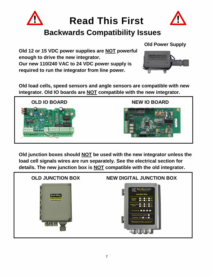
Read This First Backwards Compatibility Issues
Old Power Supply
Old 12 or 15 VDC power supplies are NOT powerful
enough to drive the new integrator.
Our new 110/240 VAC to 24 VDC power supply is
required to run the integrator from line power.
Old load cells, speed sensors and angle sensors are compatible with new
integrator. Old IO boards are NOT compatible with the new integrator.
OLD IO BOARD NEW IO BOARD
Old junction boxes should NOT be used with the new integrator unless the
load cell signals wires are run separately. See the electrical section for
details. The new junction box is NOT compatible with the old integrator.
OLD JUNCTION BOX NEW DIGITAL JUNCTION BOX

8
Unpacking The Scale
Each Belt-Way Scale is comprised of a minimum of three cartons:
One 26 in. x 10 in. x 8 in. carton contains the integrator, speed sensor,
speed sensor hardware kit, and angle sensor (if purchased with the scale).
Another 26 in x 10 in x 8 carton contains the load cell assemblies and load cell
hardware kit. Dual, triple, or quad idler scales will have multiple cartons of
load cell assemblies. Please record the load cell model number shown on
the box or on the load cell assembly. It must be entered into the integrator
during the init ial scale setup.
A third carton contains the galvanized mounting pipe. 48 in. long pipe is the
standard length, but 60 in. or 72in may be provided upon request. Dual, triple,
or quad idler scales will have multiple cartons of mounting pipe. Other cartons
will contain various accessories. Open packages carefully as they may contain
packing lists or other documentation.

9
Mechanical Installation Installation Procedure For Standard CEMA Idlers
1. Scale Placement For accessibility and belt tension reasons, we suggest mounting the scale on the lower third of the conveyor. Two idlers before and after the scale are considered to be the weighbridge. These five idlers must be in good mechanical condition, be the same trough angle, and have identical diameter rollers. It is best to mount the weighbridge idlers an equal distance apart. Skirting should not make contact with the belt in the weighing area. Material must not impact the belt near the weighbridge. Avoid using idlers close to the head or tail pulley.
2. Attach Load Cell Assemblies Remove the mounting foot from the scale idler to give clearance above the conveyor frame. 3/8" is usually enough but the area must be kept free of matierial. If the foot is not removed, the other weighbridge idlers must be shimmed to produce enough clearance. Bolt the load cell assemblies to the idler as shown using the "V-Block". The load cell cable should point downhill. Leave plenty of clearance between the load cell assembly and conveyor frame. Do not overtighten the V-Block bolts As this will twist the load cells and give false readings! They should only be tightened enough to compress the lock washer.
NOTE:Special care must be taken on stainless steel load cell assemlbies. Do not use a full thread bolt, or over tighten the existing bolt. The cable passes directly below the bolt and can be damaged. 3. Install Scale Support Pipes As Shown:(Note direction of retaining
straps) *Uphill end of the load cell assembly* The Mounting pipe must touch the front retaining strap on the high end of load cell assembly.
*Downhill end of load cell assembly* Center pipe in oval hole on low end of load cell assembly
4. Drill U-Bolt Holes
10
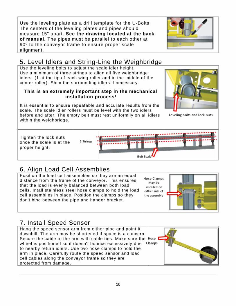
Use the leveling plate as a drill template for the U-Bolts. The centers of the leveling plates and pipes should measure 15" apart. See the drawing located at the back of manual. The pipes must be parallel to each other at
90⁰ to the conveyor frame to ensure proper scale
alignment.
5. Level Idlers and String-Line the Weighbridge
Use the leveling bolts to adjust the scale idler height. Use a minimum of three strings to align all f ive weighbridge idlers. (1 at the tip of each wing roller and in the middle of the center roller). Shim the surrounding idlers if necessary.
This is an extremely important step in the mechanical installation process!
It is essential to ensure repeatable and accurate results from the scale. The scale idler rollers must be level with the two idlers before and after. The empty belt must rest uniformily on all idlers within the weighbridge.
Tighten the lock nuts once the scale is at the
proper height.
6. Align Load Cell Assemblies Position the load cell assemblies so they are an equal distance from the frame of the conveyor. This ensures that the load is evenly balanced between both load cells. Intall stainless steel hose clamps to hold the load cell assemblies in place. Position the clamps so they don't bind between the pipe and hanger bracket.
7. Install Speed Sensor Hang the speed sensor arm from either pipe and point it downhill. The arm may be shortened if space is a concern. Secure the cable to the arm with cable ties. Make sure the wheel is positioned so it doesn't bounce excessively due to nearby return idlers. Use two hose clamps to hold the arm in place. Carefully route the speed sensor and load cell cables along the conveyor frame so they are protected from damage.

11
Mechanical Installation Channel Inset Idler (Primarily used for Portable Machines)
Many producers require a weighing solution for their portable crushers, screen plants, etc. Installing a scale on this type of equipment is possible but can be more challenging than a standard conveyor. There are to many types of portable machines to cover in t his document. This section is meant to offer broad exposure to portable equipment and not be a step by step guide. Scale accuracy and repeatability may vary greatly due factors beyond our control. We strongly suggest that you consult a Belt -Way dealer before attempting the following installation procedures.
1. Scale Placement
The same rules apply when choosing a location to install a scale on a portable machine. However, the belts are usually shorter so it may not be possible to have a 5 idler weighbridge. A three idler weighbridge may be used when necessary. The scale should not be placed near the head pulley, near a fold in the conveyor or directly under a magnet.
2. Modification of Channel Inset Idlers
Portable equipment typically employ channel inset idlers. They mount flush to the inside of the conveyor frame. These idlers may require significant modification to attach the load cell assemblies. The idler must be removed from the frame and trimmed so it no longer touches the frame at the original mounting point. A small piece of angle can be welded to the top of the idler channel to allow use of the standard V-block bracket.
We offer an alternative "Z bracket" to make the idler to load cell assembly mounting easier.
12
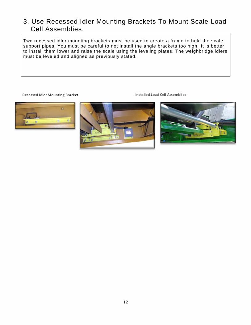
3. Use Recessed Idler Mounting Brackets To Mount Scale Load Cell Assemblies.
Two recessed idler mounting brackets must be used to create a frame to hold the scale support pipes. You must be careful to not install the angle brackets too high. It is better to install them lower and raise the scale using the leveling plates. The weighbridge idlers must be leveled and aligned as previously stated.
13
Electrical Connections
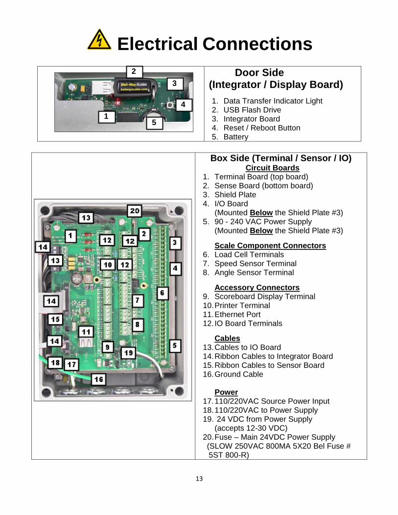
Door Side (Integrator / Display Board)
1. Data Transfer Indicator Light 2. USB Flash Drive 3. Integrator Board 4. Reset / Reboot Button 5. Battery
Box Side (Terminal / Sensor / IO) Circuit Boards 1. Terminal Board (top board) 2. Sense Board (bottom board) 3. Shield Plate 4. I/O Board (Mounted Below the Shield Plate #3) 5. 90 - 240 VAC Power Supply (Mounted Below the Shield Plate #3)
Scale Component Connectors 6. Load Cell Terminals 7. Speed Sensor Terminal 8. Angle Sensor Terminal
Accessory Connectors 9. Scoreboard Display Terminal 10. Printer Terminal 11. Ethernet Port 12. IO Board Terminals
Cables 13. Cables to IO Board 14. Ribbon Cables to Integrator Board 15. Ribbon Cables to Sensor Board 16. Ground Cable Power 17. 110/220VAC Source Power Input 18. 110/220VAC to Power Supply 19. 24 VDC from Power Supply
(accepts 12-30 VDC) 20. Fuse – Main 24VDC Power Supply (SLOW 250VAC 800MA 5X20 Bel Fuse # 5ST 800-R)
2
1
3
4
5

14
WARNING! There is high voltage inside the scale integrator box so please make sure the supply power to the scale
integrator has been unplugged or disconnected at the circuit breaker to reduce the possibility of
electrocution and injury.
Make sure you LOCK OUT, TAG OUT and TRY OUT the electrical system before continuing with any
maintenance or service. Please follow all Federal, State and Company Safety procedures and policies
when working with this product.
Cable Basics: All components wiring must be connected as shown below.
Installing the load cell shield wire this way will ground it to the integrator and reduce
any noise inside the scale. When installing 3 or more load cells you will need to strip
the wiring back to get additional length and keep the shield wire out of the Integrator.
1. The complete cable needs to be fed through the
grommet hole.
2. The shield then needs to be wrapped backwards over
the grommet and fed through the cord grip nut.
3. Insert the cable through the hole in the integrator
enclosure so that the cord grip presses the shield
against the housing as the nut is tightened.
1. Load Cell
Connect the wires for each load cell to a LC terminal as shown below. You can independently
connect up to 8 load cells to the sensor board. You must to start at LC1 (bottom) and work your
way upwards as the scale will only monitor the terminals based on the number of load cells
selected during the setup process.
If multiple load cells are summed in a junction box prior to connection to the
integrator, you MUST jumper +SIG of LC1 to +SIG of LC2 and -SIG of LC1 to -SIG of
LC2! Additionally jumper LC1 to LC3 and LC4 if 4 load cells are used.
USE CORRECT WIRING FOR YOUR LOAD CELLS!
All Aluminum & 350 KG Stainless
50, 100, 150 KG Stainless
500 & 1000 KG Stainless
BLACK = -SUP BLACK = -SUP BLACK = -SUP
RED = +SUP GREEN = +SUP GREEN = +SUP
WHITE = -SIG WHITE = -SIG RED = -SIG
GREEN = +SIG RED = +SIG WHITE = +SIG
SHIELD = Cord Grip SHIELD = Cord Grip SHIELD = Cord Grip

15
2. Speed Sensor
For standard return belt speed sensor and shaft mounted speed sensor
There are some empty slots on the terminal strip. These slots are for future product
upgrades and should be left empty when installing the speed sensor.
3. Angle Sensor
Please connect the wires for the angle sensor to the ANGLE terminal as shown:
4. 110/220VAC Supply Power
The 110/220 VAC power supply is an optional component of the integrator! It can be installed prior to
shipment from the factory (Part # BWPS) or shipped as a field installable kit. (Part # BWPSKIT).
WARNING - HIGH VOLTAGE!! Make sure you follow best safety practices!
Double check to be sure there is no power on the wires while making the connections!
Use a small screw driver to
remove the connector as shown.
Other methods may result in
damage to the connector or
circuit board!
LINE NEUTRAL EARTH GROUND

16
5. 12-30VDC Supply Power on Terminal Board
The standard Scale is DC powered only!
You may power the integrator from another 12-30 VDC source when 110/220
VAC is not available. Approximately 55 watts of power are required to run the
integrator. We recommend a DC spike filter (Part # PRD0085) when alternative
sources of DC power must be used
6. Power Supply Field Installation Kit
The field installation kit is shipped pre-wired complete with push on terminals for the terminal
board. Follow the following steps to add the AC power supply to a DC powered Integrator.
WARNING!!
HIGH VOLTAGE
Make sure you follow best safety practices and that there is no power on the wires while
making the connections when adding the Field Installation kit or you can be electrocuted
or damage to the scale integrator could occur.
1. 12-30VDC - OUT This DC Voltage is being sent from the power supply to the Terminal board for scale integrator power. It plugs into connector on terminal board as shown in #4 above.
2. 110-220 VAC - IN This AC Voltage is being received from the supply power terminal on the terminal board, converted to DC power, and sent to the terminal as described above in 1.
3. The input Voltage comes from the source and the power supply converts the 110/220 VAC to DC
power for scale integrator use. Plugs into connector on terminal board as shown in #5 above.

17
7. I/O Board
A relay MAY NOT be used as a pulsed outputs (Remote Totalizer).
Please use an external solid state Relay for this purpose.
(Belt-Way Part # REL0015)
All analog, digital Inputs & outputs are isolated for external Sources.
There is No channel to channel isolation.

18
User Interface Navigation Home Press the Home key to display the currently selected Run Screen.
Main Menu Press the Main Menu key to display the Main Menu.
Back Press the Back key to return to the previous screen.
Zero Calibration Press the Zero Cal key to start a zero calibration
Print Ticket Press the Print Ticket key to print a ticket
Clear Weight Press the Clear Weight key twice to clear the accumulated weight total to zero
Navigation Arrows All arrows are used to navigate menus, and virtual keypads.
The Left & Right Arrows toggle the focus between a virtual keypad and the option list.
The up and down arrows scroll through option lists.
Some arrows are also used for special functions as described on those function screens.
The Enter key is used to Accept, Verify, Acknowledge, Continue, and Select options.
Entering Alphanumeric values on Virtual Keypads Press ENTER on the manual keypad after highlighting each character. When you
have completed your entries select ENTER on the virtual keypad to save.

19
Setup Wizard The Setup Wizard is an intuitive tool designed to assist you in setting up the scale for the first time
in an easy to follow sequence.
We strongly recommend completing the Setup Wizard for each newly installed scale!
If you EXIT the Setup Wizard before it is completed you would need to start at the beginning of the Setup Wizard upon re-entering the Wizard. Your previous entries and selections will be saved from your previous session.
You can also make parameter selections / entries and conduct calibrations by accessing
the Scale setup and Calibration menus directly.
Several measurements are required to complete the wizard. It is best to record the following before starting the wizard:
1. Number of Weigh Idlers 2. Conveyor Angle (NO Angle Sensor installed)
3. Idler spacing (center to center distance) 4. Load Cell Capacity / Model
The Setup Wizard will assist to setup of the following parameters and calibrations:
1) Select Run Mode 2) Select Number of Weigh Idlers 3) Select Load Cell Size 4) Select Distance Units 5) Select Weight Units 6) Select Decimal Places 7) Select Rate Time Units 8) Select Angle Sensor ON/OFF
9) Enter Angle 10) Enter Idler Spacing 11) Speed Wheel Diameter 12) Speed Wheel Pulses / Revolution 13) Select I/O Board Installed/ Not Installed 14) Belt Length Entry or Calibration 15) Zero Calibration Static or Dynamic
Span Calibration - Option of Manual, Test Weight & Material Test
Navigation Tip
Press the MENU key.
Navigate to the SETUP WIZARD icon and press ENTER key
FOLLOW THE STEP BY STEP SCREEN INSTRUCTIONS
Press the BACK key go back to the previous screen

20
Scale Setup The Scale Setup menu is available to manage various parameters as well as to directly edit or view
the current selection. You can configure the scale manually in this menu instead of following the
Setup Wizard. You will need to complete all the calibrations after doing any setup or some changes
in this menu.
The Scale Setup menu will run you through the setup of the following scale functions:
1. Run Mode
The Run Mode selection determines what the scale screen will look like and how it will
function.
There are five different run modes to choose from.
Weight / Rate
This mode displays the accumulated weight as the primary unit. This screen also
displays:
The Scale Setup menu will allow you to setup and view the following scale parameters:
1) Run Mode 2) Number of Weigh Idlers 3) Load Cell Size 4) Distance Units 5) Weight Units 6) Rate Time Units 7) Conveyor Angle 8) Idler Distance 9) Speed Sensor 10) Decimal Places 11) I/O Option Board
Navigation Tip
Press the MENU key.
Navigate to the SCALE SETUP icon and press the ENTER key
FOLLOW THE STEP BY STEP SCREEN INSTRUCTIONS
Press the BACK key go back to the previous screen

21
CURRENT RATE (tons per hour)
CURRENT SPEED
Load Out
The Load Out mode displays the Target weight of the current load or Batch.
This screen also displays:
CUTOFF WEIGHT
CURRENT WEIGHT
CURRENT RATE
Blending
The Blending mode displays:
SET RATE
CURRENT RATE
SETPOINT %
ACCUMULATED WEIGHT
Load Control
The load control mode displays the current scale load as a weight / distance unit.
The unit shown depends on the units selected during unit setup section.
Lbs/ft
Kg/m
Etc.
Rate Control
The rate control mode displays the current material flow across the scale as a
weight / time unit. The unit shown depends on the units selected during unit setup
section.
Lbs/min
Tons/hr
Tonnes/hr
etc.
2. Number of Weigh Idlers
This is where you would select how many idlers you are weighing with load cell
assemblies. Choices are:
1, 2, 3 or 4 idlers.
3. Load Cell Size
This is where you would select the load cell capacity of the load cell assemblies used for
this scale. Choices are:
45 kg (Aluminum)
50 kg (Stainless)
100 kg (Aluminum or Stainless)

22
150 kg (Stainless)
200 kg (Aluminum)
350 kg (Stainless)
500 kg (Aluminum or Stainless)
1000 kg (Aluminum or Stainless)
1000 lbs (Catenary Idler Scale)
Custom (See Note)
All load Cell mV/V specifications are pre-programmed in the software.
For Custom you need to know the Load Cell Capacity and mV/V
4. Weight Units
Select the distance units you would like to display on the screen during operation.
Depending Distance unit selection, the choices are:
I. English
Pounds
Tons
Long Tons II. Metric
Tonne (Metric Tons)
kg
5. Distance Units
Select the distance units you would like to display on the screen during operation. The
units displayed are related to the distance units previously selected. EXAMPLE: If you
select English Units the choices shown will be as listed under English units.
Choices are:
III. English Units
Feet
Inches
Tons
Long Tons IV. Metric Units
Meters
Centimeters
Tonnes (Metric Tons)
Kilograms
6. Rate Time Units
Select the time based units you would like to display when in run mode.
Choices are:
Minute (min)
Hour (Hr)

23
7. Conveyor Angle
You need to select whether you have an angle installed.
Installed: The scale will automatically look at the signals for the angle sensor and use
these signals for weight calculation.
Not Installed: You need to enter the angle of the conveyor as this effects the weight
calculation.
If you do not have an “Angle Finder”, you can download a free Inclinometer
application on your smart phone to help find the angle in degrees.
8. Idler Distance
You need to enter the exact distance between the conveyor idlers and the scale idlers so
that the scale can accurately measure the weight on the belt. The measurement units
required for entry are dependent on the distance units selected in #5:
English: Inches (in)
Metric: Meters (m)
9. Speed Sensor
The speed sensor default shown is for the “Return Belt Speed Sensor” however you are
able to use Belt-Way Scales shaft mount encoder or a third party encoder for speed
measurement. In order to get an accurate speed you would need change the following
values:
A. Wheel diameter:
If you are using the Belt-Way Scales shaft mount encoder you will need to
measure the pulley diameter that the encoder is mounted to. This measurement
needs to be in Inches or Centimeters.
B. Pulses Per revolution:
If you are using a third party encoder you need to enter the pulses/revolution for
that encoder so that the scale can read and display the speed correctly.
C. User Belt Speed
If the scales displayed belt speed is not correct and does not match the reading
from your tachometer. You can adjust the scales displayed reading to match. You
must know the pulses per revolution of the encoder being used and the correct
belt speed which you can enter here and the scale will adjust the pulley diameter
so the displayed belt speed will match the actual speed.

24
Calibration The calibration menu is available to go to a specific type of calibration you would like to
perform. Each calibration can be performed independently for a specific purpose. For more
information on each calibration please continue reading.
A report of all calibration activity is stored on the USB drive.
See Device Setup / USB for more details.
SELECTION OPTIONS DURING AND AFTER THE CALIBRATIONS PROCEDURES
Press the Up Arrow to go to the PREVIOUS screen
Press the Left Arrow to CANCEL
Press Right Arrow to CHANGE THE VALUE
Press the ENTER key to ACCEPT / ACKNOWLEDGE.
The different types of calibration that can be performed from this menu are:
1) Test Weight Calibration 2) Material Test Calibration 3) Digital Calibration 4) Belt Length Calibration 5) Zero Calibration (Initial)
6) Zero Calibration (Routine) Started by pressing the Zero Key On the keypad in Run Mode.

25
Test Weight Calibration
The Test Weight Calibration requires static test weights and a test bar to hang the test weights. Other methods may be used as long as the weights hang freely from the scale idler or load cell assemblies. Suggested test weight amounts are as follows:
Model 45 or Model 50
Model 100 or Model 150
Model 200 Model 350 Model 500 Model 1000
25-50 lbs. 50-100 lbs. 75-125 lbs. 125-200 lbs. 200+ lbs. 250+ lbs.
There are two styles of test weights that could be used for calibration:
1. Self-Storing Test Weight System – This test weight storing system can be added to any
existing scale or purchased with new scales. The total weight recorded and marked on the
sticker at the scale
2. Old Style Test Weights – Test weights and Test Weight Bar must be weighed and entered
as a combined total weight.
STOP the belt and please make sure you follow all safety procedures when placing test
weights in position on the scale for the test weight
The unit of weight entered is in Pounds (lbs.) or Kilograms (kg’s) depending on the units selected
during the scale setup.
The Trim Factor of a properly calibrated scale should be close to 1. (.95, 1.1, etc) If your result is not close to 1 recheck all settings and perform the calibration again!
------------------------------------------------------------------------------------------------------------
Navigation Tip
Press the MENU key.
Navigate to the CALIBRATION icon and press ENTER key
Navigate to the TEST WEIGHT menu. Then press ENTER key.

26
Material Test Calibration
The Material Test Calibration is one method that can be used to calibrate the scale and is based on the
weight measured by the Belt scale and a Certified scale (typically a truck scale).
These two weights are entered into the scale and after acknowledging the entries, the scale will adjust
the TRIM factor so that the belt scale will read very close to the certified scale.
The CERTIFIED scale units entered is selectable and does not need to be the same
as the belt scale units because the scale will convert and adjust the scale as needed
based on the units selected for the certified. The CERTIFIED scale unit choices are:
Tons (Equal to 2000lbs)
Long Ton (Equal to 2240lbs)
Pounds (lbs.)
Metric Tons (Tonne)
Kilograms (KG)
Recommended steps to follow:
1. Weigh the truck EMPTY to get a good tare weight.
2. Make sure the scale ZERO Calibration is good. Zero Calibrate the scale if needed.
3. Clear the TOTAL weight on the belt scale.
4. Run the material to start test
5. Complete 3 tests. We recommend a minimum of 15 tons per test if possible
6. Compare the results to prove the scale is repeatable BEFORE adjusting the scale calibration.
7. If all tests are reasonably consistent, take an average of the belt scale and truck scale tests, or
simply add the tests up and enter the total weight for the belt scale and truck scale, instead of a
single load. Either of these methods will result in a more accurate calibration.
The Trim Factor of a properly calibrated scale should be close to 1. (.95, 1.1, etc.) If your result is not close to 1 recheck all settings and perform the calibration again!
------------------------------------------------------------------------------------------------------------
Navigation Tip
Press the MENU key.
Navigate to the CALIBRATION icon and press ENTER key
Navigate to the MATERIAL TEST menu. Then press ENTER key.

27
Digital Calibration
The Digital Calibration is a quick electronic calibration which restores the Trim Factor back to the
default of 1.
-------------------------------------------------------------------------------------------------------------
Belt Length Calibration
The Belt Length Calibration calculates the length of the belt. This must be performed before other
Zero Calibration methods will work properly.
You have various options when doing this calibration:
1. Length and Zero
This calibration measures the length of the belt while also conducting an Initial Zero calibration
while the belt is running and empty. When this calibration is completed the scale will know how
long the belt is in Meters (m) or Feet (Ft) depending on the units selected during setup. The
scale will also be zero calibrated.
Navigation Tip
Press the MENU key.
Navigate to the CALIBRATION icon and press the ENTER key
Navigate to the DIGITAL CALIBRATION. Then press the ENTER key.
Navigation Tip
Press the MENU key.
Navigate to the CALIBRATION icon and press the ENTER key
Navigate to the BELT LENGTH CALIBRATION. Then press the ENTER key.

28
The belt must be RUNNING and EMPTY to perform this calibration.
2. Auto Belt length
This calibration is performed while the belt is running empty and only measures the length of the
belt.
You need to do the following steps to complete this calibration:
1. Mark the belt
2. Mark a point on the conveyor
3. Start the conveyor
4. Follow the prompts on the display. To START measuring the length press the ENTER key
when the belt mark passes the conveyor frame mark. To END the measurement press the
ENTER key when the belt mark passes the conveyor mark after 1 revolution.
3. Manual Belt length
If you have the exact length of the belt then you would enter this length here to avoid doing
option 1 or 2. The acceptable units would be the same as selected during scale setup.
Feet (Ft) or
Meters (m)
Zero Calibration (from the Calibration Menu)
The Zero Calibration must be performed when the scale is first installed or if a significant change has
occurred to the scale or conveyor. This does not measure the belt length. This calibration is done so
that the scale knows the weight of the empty conveyor belting while it is running. The scale would then
store this value and subtract it during normal operations so that you see just the material weight on the
belt.
Navigation Tip
Press the MENU key.
Navigate to the CALIBRATION icon and press the ENTER key
Navigate to the ZERO CALIBRATION. Then press the ENTER key.
OPTIONS AVAILABLE BEFORE ACCEPTING THE CALIBRATION PROCEDURE
Press the Up Arrow to REJECT and REPEAT the calibration

29
There are 2 options when doing the Initial Zero Calibration.
1. Dynamic – This calibration is done when the belt is Running Empty
The Dynamic Initial Calibration is also accessible through the Setup Wizard or it can
be done simultaneously when doing Length and Zero Calibration during the Belt
Length Calibration.
You will also notice that this calibration requires the conveyor to complete 3 revolutions
of the belt.
2. Static – This option is used when you are unable to start the belt and need to complete a
quick zero Calibration.
The belt must be STOPPED and EMPTY when doing this calibration.
------------------------------------------------------------------------------------------------------------
Zero Calibration – (from the Keypad)
This is the primary method for performing a ZERO CALIBRATION. We recommend repeating this
process daily or as frequently as required by your application. Run the belt EMPTY and press the
ZERO CALIBRATION button on the keypad. You can cancel the calibration at any time by pressing the
BACK or HOME buttons. Follow the on screen instructions to save the new zero number.
Some factors that the Routine or Daily zero calibration will help compensate for are:
Material build up on the scale
Material build up on the belt
Ambient Temperature changes
Belt temperature changes
Added belt splices and vulcanizing
Misalignment of the belt (belt tracking)
The zero calibration will overcome some of these issues but is not a replacement for routine
maintenance.
Press the Left Arrow to REJECT and CANCEL
Press Right Arrow to ACCEPT and REPEAT
Press the ENTER key to ACCEPT / ACKNOWLEDGE.

30
Device Setup
The device setup menu is used to activate all peripheral devices.
Printer
Tickets On / Off - Enable ticket printing.
Printer Type: Setup parameters for your printer.
Default settings:
Belt-Way printer
RS232 port
Baud rate - 9600
Data Bits - 8
Stop Bits - 1
Flow Control – None
The Custom option allows 3rd party printers to be used.
RS232 port parameters must be set to match the printer you are going to use.
Available Selections:
Baud Rate: 9600, 19200, 57600 or 115200
Data Bits: 7 or 8
Stop Bit: 1 or 2
Flow Control: None, Hardware Xon – Xoff
Setup Ticket:
Enter the following:
Company Name
Address
Phone Number.
Press the PRINT key to print the ticket.
----------------------------------------------------------------------------------------------------------
1. Printer 2. Scoreboard Display 3. USB 4. I/O Board 5. Controls 6. Plant Connect

31
Scoreboard Display
Displayed Data - Choose the data you want to view on the display Weight: Shows only accumulated weight
Rate: Shows only tons per hour.
Alternate: Shows both weight and rate.
Time Delay - Defines how many seconds each value is displayed.
SB Display Type - Setup parameters for your display.
Default settings:
Belt-Way Display
RS232 port
Baud rate - 9600
Data Bits - 8
Stop Bits - 1
Flow Control – None
The Custom option allows 3rd party printers to be used.
RS232 port parameters must be set to match the display you are going to use.
Available Selections:
Baud Rate: 9600, 19200, 57600 or 115200
Data Bits: 7 or 8
Stop Bit: 1 or 2
----------------------------------------------------------------------------------------------------------
USB Enable data logging to the USB flash drive. Files are saved in “.txt” format.
Calibration Report:
Saves the following data to calib_report.txt when a calibration event occurs.
Data Type REP
Report Type Cal Report
Date 2013/1/6
Time 3:41:1
Scale name BELTWAY
Plant name BELTWAY USA
Product name ROCKS
Previous nos of pulses 9
Previous time duration 51.501999
New nos of pulses 24
New time duration 49.249001

32
Prev set zero value 169.154160
New set zero value 329.742950
Set Zero Accumulated Weight 329.742950
Accumulated weight unit Tons
Set Zero Angle 12.000000
Accumulated weight 0.4
Accumulated weight unit Tons
Certified weight 11.000000
Certified weight unit Tons
Previous Calibration factor 10.000000
Calibration factor 0.083333
Idler_spacing1 48.000027
Idler_spacing2 48.000027
Idler_spacing3 48.000027
Calibration type 4
Calibration Log:
Saves the following record to calib_log.txt when a calibration event occurs.
Type ID #
Date Time Total Weight
Certified Weight
Old Trim Factor
New Trim Factor
CAL XX YYYY/MM/DD HH:MM:SS XXXX.X X.X XXXX.X Tons, Etc.
Zero Log:
Saves the following record to calib_log.txt when a zero calibration event occurs.
Type ID #
Date Time Previous Zero Value
New Zero Value
Total Weight
Unit Angle
ZER XX YYYY/MM/DD HH:MM:SS XXX.XXX XXX.XXX XXXX.X Tons, lbs, Etc. XX.X
Runtime Report:
Saves the following record to daily_report.txt once per day. Data Type REP
Report Type Daily Report
Date 2013/1/7
Time 0:0:0
Scale name BELTWAY
Plant name BELTWAY USA
Product name ROCKS
Start Time 0:0:0
Start Load Time 0:0:0
End Load Time 23:22:0
End Time 23:22:0
Run Time 688
Down Time 0
Total Time 688
Number of starts/stops 0
Average Rate 0.27
Rate Unit Hour
Total Weight 186.13
Weight Unit Tons
33
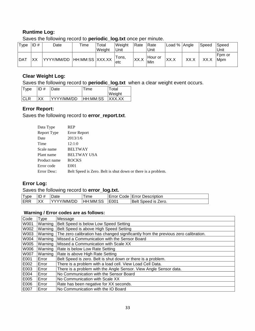
Runtime Log:
Saves the following record to periodic_log.txt once per minute.
Type ID # Date Time Total Weight
Weight Unit
Rate Rate Unit
Load % Angle Speed Speed Unit
DAT XX YYYY/MM/DD HH:MM:SS XXX.XX Tons, etc
XX.X Hour or Min
XX.X XX.X XX.X Fpm or Mpm
Clear Weight Log:
Saves the following record to periodic_log.txt when a clear weight event occurs.
Type ID # Date Time Total Weight
CLR XX YYYY/MM/DD HH:MM:SS XXX.XX
Error Report:
Saves the following record to error_report.txt.
Data Type REP
Report Type Error Report
Date 2013/1/6
Time 12:1:0
Scale name BELTWAY
Plant name BELTWAY USA
Product name ROCKS
Error code E001
Error Desc: Belt Speed is Zero. Belt is shut down or there is a problem.
Error Log:
Saves the following record to error_log.txt.
Type ID # Date Time Error Code Error Description
ERR XX YYYY/MM/DD HH:MM:SS E001 Belt Speed is Zero.
Warning / Error codes are as follows:
Code Type Message
W001 Warning Belt Speed is below Low Speed Setting
W002 Warning Belt Speed is above High Speed Setting
W003 Warning The zero calibration has changed significantly from the previous zero calibration.
W004 Warning Missed a Communication with the Sensor Board
W005 Warning Missed a Communication with Scale XX
W006 Warning Rate is below Low Rate Setting
W007 Warning Rate is above High Rate Setting
E001 Error Belt Speed is zero. Belt is shut down or there is a problem.
E002 Error There is a problem with a load cell. View Load Cell Data.
E003 Error There is a problem with the Angle Sensor. View Angle Sensor data.
E004 Error No Communication with the Sensor Board
E005 Error No Communication with Scale XX
E006 Error Rate has been negative for XX seconds.
E007 Error No Communication with the IO Board

34
I/O Board
Assign Inputs
Assign any one of the listed input functions to any of the 4 digital inputs. The digital inputs are optically
isolated and accept 5-30 VDC.
Input options are listed below:
1. Print Ticket - Prints a ticket if a printer is connected to the integrator.
2. Print then Clear - Prints a ticket first and then resets the Accumulated Weight to zero.
3. Enter Load - Used with legacy remote start stop stations.
4. PID Rate = Zero - Momentarily stops PID loop from calculating.
5. Zero Calibration - Initiates the dynamic Zero Calibration.
6. Error Acknowledge - Acknowledge and clear an error condition.
Assign Outputs
Assign any one of the listed output functions to any of the 3 digital outputs. The digital outputs are
optically isolated with a maximum of 30 VDC, 100 mA sinking.
A solid state relay may be required to connect the output to a 110 / 220 VAC PLC input
card.
Output Options are listed below:
1. Pulsed Output - Generates a pulse for each accumulated weight unit.
Pressing Enter will take you to the next setup screen where you must program the Weight per Pulse and Pulse on Time values.
Weight per Pulse This can be set to .1, 1.0, 10 or 100 of the selected Weight Units.
For example, if the Weight unit is Tons and the Weight per Pulse is set to .1, a pulse will occur each time 0.1 Tons is accumulated. Please note that small pulse values (.1 or 1.0) will not work with small Weight units (Lbs or Kgs) as an excessive number of pulses will be created!

35
Pulse on Time controls how long the pulse remains on. The value is in milliseconds. This must be programmed properly so the control system can count each pulse.
2. Quadrature Wave - Allows a pulsed output to count positive or negative weight. This
requires
a second output to be programmed as the Pulsed Output channel.
3. Error Alarm - The alarm output will turn on when an error condition occurs.
Pressing the ENTER key will allow you to choose the error you wish to monitor with the
output.
1. Load Cell - Activates when any load cell malfunctions.
2. Angle Sensor - Activates when the angle sensor malfunctions.
3. Communications - Activates when there is any communication error.
4. Negative Rate - Activates when the rate drops below the Negative Rate Limit.
The Negative Rate Limit is programmed in the Admin / Settings menu.
5. Any Error - Activates when any of the previously mentioned errors occur.
6. Min/Max Speed - Activates when the speed is above or below the programmed.
Pressing Enter takes you to the setup screen where you must program the Min or Speed
Setpoints
Min Speed Output (Turns on when speed is below setpoint) or
Max Speed Output (turns on when speed is above setpoint).
7. Min/Max Rate - Activates when the rate is above or below the programmed.
Pressing Enter takes you to the setup screen where you must program the Min or Max Rate
Setpoint
Min Rate Output (Turns on when rate is below setpoint) or
Max Rate Output (turns on when rate is above setpoint).
8. Batching / Loadout - Activates when a batch is complete.
9. Zero Calibration - Activates when a Zero Calibration is in progress. Be sure to
assign
an input to initiate the Zero Calibration.
Assign Relays
Any one of the previously listed output functions can be assigned to any of the 3 relay outputs.
All digital output options EXCEPT pulsed outputs are available as relay outputs.
The relays can accept a direct connection to a 100 / 240 VAC input.

36
Analog Outputs
Selection choices are 4-20 mA or 0-20 mA output. This output is used by a PLC system to monitor
scale flow rate (tons per hour etc.) or to automatically control a material feed device in blending, rate
control or load control applications if configured to do so.
1. Analog 1 Function –
Output Default - Unassigned
Selection choices available are:
0-20 mA
0 mA is the mA output when the scale rate is 0 (Tph, Kg’s / Hr)
20 mA is the maximum output when the scale rate exceeds the Max Rate value.
4-20 mA
4 mA is the mA output when the scale rate is 0 (Tph, Kg’s / Hr)
20 mA is the maximum output when the scale rate exceeds the Max Rate value.
2. Analog 1 Setpoint
Default - 100%
The setpoint determines what portion of the 4-20 mA output is sent to the PLC or feed
device. 100% sends the entire value,
50% sends half the value,
10% sends one tenth of the value, etc.
The value should remain at 100% when the output is simply monitored by a control
system. It should be programmed to the required value when the scale is used for
blending.
3. Analog 1 Max Rate - The Max Rate establishes the 20 mA level for the analog output.
The default is 500.
The Max Rate MUST equal the PLC 20 mA value to make the scale and PLC rate readings match.
----------------------------------------------------------------------------------------------------------
Controls
PID Control
These settings are used to control feed devices. A PID control loop allows a scale to speed up or slow
down a feed device in order to keep with a programmed flow rate crossing the scale.

37
The PID control section is a generic setup for the other specific functions (Rate Control, Blending, etc).
PID Channel
Default – 1
Selection options are: 1 or 2
This is the analog output that will control the feed device.
PID Action
Default - Reverse Action
Selection options are:
1. Reverse Action
This method causes the feed device to speed up when the actual flow rate
drops below the programmed flow rate, thus increasing the flow rate.
2. Forward Action
This method causes the feed device to slow down when the actual rate is
below the programmed rate. It can be used to control a conveyor belt to keep
a consistent level of material on the belt.
PID Setpoint
The PID Setpoint is the programmed flow rate that the scale attempts to maintain
when running a PID control loop.
Default - Local Setpoint
Selection options are:
1. Local Setpoint
The Local setpoint must be manually entered into the integrator.
2. Remote Setpoint
Remote setpoint requires a separate scale to automatically update the
setpoint value in a Master - Slave configuration. See blending section for more
details.
P, I, D Terms
The default PID terms will work for most applications. However, they may be adjusted
to fine tune feeder performance. Be careful when changing the values as they may
result in abnormal feeder behavior. Contact Belt-Way with questions about PID
control setup.
38
Load Out
This setting stops a feed device after a predetermined weight has crossed the scale and is primarily
used to automate truck and rail car loading.
8 Preset Load Weights can be programmed accommodate different size vehicles.
Each load weight can also be accompanied by a Cutoff value. The Cutoff value must
match the amount of material that is left on the conveyor after a load is complete. The
Cutoff will usually be the same for each load weight, but different values can be used if
multiple feeders are utilized in the loading process. The Cutoff must be calculated by trial
and error testing. The final Target Weight equals the Preset Load weight minus the set
Cutoff value.
Blending
Blending automatically controls one or multiple feed devices to create an accurately blended mixture of
materials. A Master - Slave configuration is utilized to have one scale send its rate to the other
networked scales.
Examples of blending include:
Mixing cement and water in a batching plant
Adding RAP to an asphalt mixture
Mixing several sizes of sand into a final product
Settings for the blending functions are:
Number of Slaves
This must be set in the Master scale only. It determines how many scales are on the
network.
Ingredient %
This is the percentage (%) of the master scale that a slave scale needs to add to the
final mixture.
Feed Delay
The Feed Delay is programmed in Seconds (s). It delays the feeder from starting if it
is a long distance from the scale.
Preload Delay
The Preload Delay is programmed in Seconds (s). It delays the Slave scale from
responding to the master scale's rate. The feeder will run a lower "bias" rate until the
delay timer expires.
Feeder Capacity - Expected capacity of the feed device.

39
Rate Control
Rate Control allows the scale to automatically adjust a VFD (variable frequency drive) for a feeder to
keep a consistent flow rate on the scale at all times. It is also possible to control vibratory feeders,
Augers, conveyors and other material feed systems.
Rate Control settings are as follows:
Target Rate
This is the RATE the scale is attempting to maintain.
Preload Delay
This will Delay the PID loop calculations if the scale is a long distance away from the
feed device. It is measured in Seconds (s).
Load Control
Load control allows the scale to automatically adjust the conveyor belt speed via a
variable frequency drive to keep a consistent belt load on the scale at all times (lbs / ft
or kgs / M.)
This method can dramatically reduce the scale's expected margin of error.
Target Load
The scale will attempt to keep the same or consistent amount of material on the belt at
all times. It must be in lbs / ft or kgs / M.
Min. Belt Speed
This is the minimum expected belt speed of the conveyor.
Preload Distance
This is the distance from the feed device to the scale.
Empty Belt Speed
This is the expected belt speed of the conveyor when it is running empty.
----------------------------------------------------------------------------------------------------------
Plant Connect
Plant Connect is an Internet based reporting system that allows you to easily access and
monitor production from a PC, smart phone or Tablet. Contact Belt-Way Scales for more
information.

40
Diagnostics The Diagnostic menu is used to visually display the status of current connections, scale settings
and live data that is sent to and received by the sensors and devices.
Current Settings is the way the scale is currently setup or calibrated
Current live data is a measured reading typically relating to the supply or signal voltage or
frequency to and from the scale components and secondary devices.
Please note you can only view these values and not edit them.
You can view the status of the settings and live data for the following menus:
You can view the status of the settings and live data for the following menus:
1) Setup Information 2) Sensors 3) I/O 4) Voltages 5) Communications 6) Calibration
Navigation Tip
Press the MENU key.
Navigate to the REPORTS AND DIAGNOSTICS icon and press ENTER key
Navigate to the DIAGNOSTICS icon and press ENTER key
Navigate to the SETUP INFO icon. Then press ENTER key.

41
Setup Information
The setup section displays the information entered when setting up the scale. This information is
related to the load cell selection, conveyor angle, and idler spacing as well how many weigh idlers are
used.
----------------------------------------------------------------------------------------------------------
Sensors The Sensors menu will enable you to view the current signals from the scale component
sensors at that point in time.
1. Load Cell 1-8
The scale will accommodate up to 8 load cell connections which means the integrator would
accommodate up to a quad idler scale (4 Idlers). Unless a junction box with custom
connections is used each load cell signal will be independent making trouble shooting quick
and easy.
Units displayed are Milli. Volts (mV)
The sensor signals available for viewing in this section are:
1. Load Cell (mV) 2. Speed Sensor (Hz) 3. Angle sensor (Degrees)
Navigation Tip
Press the MENU key.
Navigate to the REPORTS AND DIAGNOSTICS icon and press ENTER key
Navigate to the DIAGNOSTICS icon and press ENTER key
Navigate to the SENSORS icon. Then press ENTER key.

42
2. Speed Sensor
The scale speed sensor will send back a signal measured as frequency (Hz). Because the
speed sensor generates the frequency, the belt needs to run in order to show a signal coming
back. If the signal shows 0Hz while the belt is running there is an issue with the speed sensor,
wiring or integrator. Please refer to the trouble shooting section for more details on diagnosing
the problem.
3. Angle sensor
The angle sensor sends back a signal that is converted and displayed in degrees. This
refers to conveyor angle related to the horizontal position and is installed on the conveyor
frame. The sensor is suited for mobile or portable applications for conveyors that change
vertical angle, traverse and mobile conveyors that get moved often. The angle sensor
sends a signal back to the integrator which then displays the angle in degrees for the
conveyor. This angle is used in the weight calculation to compensate.
------------------------------------------------------------------------------------------------------------
I/O
Selecting the I/O menu allows you to view the current status of the input and output functions for the scale. These selections can only viewed and cannot be changed or edited while in this menu.
IO options include the following:
1. Digital Inputs 2. Digital Outputs 3. Relay Outputs 4. Analog Outputs 5. PID Control
Navigation Tip
Press the MENU key.
Navigate to the REPORTS AND DIAGNOSTICS icon and press ENTER key
Navigate to the DIAGNOSTICS icon and press ENTER key
Navigate to the I/O icon. Then press ENTER key.

43
Digital Inputs
You are able to view the status of the 4 Digital Inputs and what they are assigned to.
The default is Unassigned / OFF
Digital Outputs
You are able to view the status of the 3 Digital Outputs and what they are assigned to.
The default is Unassigned / OFF
Relay Outputs
You are able to view the status of the 3 Relay Outputs and what they are assigned to.
The default is Unassigned / OFF
Analog Outputs
You are able to view the selected status of the 2 Analog Outputs.
The default is Output 4-20mA / ON
PID Control
You are able to view the status of the various PID loop settings.
Defaults are as Follows:
PID Channel – 1
PID Action – Reverse Action
PID Setpoint – Local Setpoint
PID Set Rate – OFF
Proportional Term – 1
Derivative Term – 1
Consult Device Setup for instructions to configure these items options.
Voltages
The Voltages menu simply displays the excitation (Supply) voltage for the load cells and the
speed sensor.
Navigation Tip
Press the MENU key.
Navigate to the REPORTS AND DIAGNOSTICS icon and press ENTER key
Navigate to the DIAGNOSTICS icon and press ENTER key

44
Communication
The Communication menu will show the current setting status of all communications ports.
Calibration
Navigate to the VOLTAGES icon. Then press ENTER key.
Selecting Communication will allow you to view the current settings for the following:
1. RS-485 Port 1 and 2 2. RS-232 Port 1 and 2
3. Ethernet 4. SPI
Navigation Tip
Press the MENU key.
Navigate to the REPORTS AND DIAGNOSTICS icon and press ENTER key
Navigate to the DIAGNOSTICS icon and press ENTER key
Navigate to the COMMUNICATION icon. Then press ENTER key.
Calibration will allow you to view the current values stored for the following calibrations:
1. Trim Factor 2. Zero Number 3. Belt Length

45
1) Trim Factor
The Trim Factor is a factor used in the weight calculation and has no unit value.
2) Zero Value
This is the weight of the empty belt measured in the selected units during setup.
Measured in Pounds (lbs.) or Kilograms (kgs)
3) Belt Length
This is the measured length of the belt as measured during the length calibration. This
is shown in meters (m) or feet (Ft.).
Navigation Tip
Press the MENU key.
Navigate to the REPORTS AND DIAGNOSTICS icon and press ENTER key
Navigate to the DIAGNOSTICS icon and press ENTER key
Navigate to the CALIBRATION icon. Then press ENTER key.

46
Administration The administration menu is available to manage various parameters as well as to provide
additional protection for the scale settings and functions by means of an administrator’s
password. This is commonly used at locations where settings could be changed by accident
by non-trained personnel affecting scale performance and accuracy as well as causing data or
connectivity issues.
The administration section will run you through the setup of the following scale functions:
Settings
The administration section will run you through the setup of the following scale functions:
1. Settings 2. Selection Run Mode 3. Security 4. Update Firmware 5. Calibration 6. Ethernet
The settings menu will allow you to access the following parameters for setup:
1. Scale Name 2. Plant Name 3. Product Name 4. Current Date 5. Current Time
6. Auto Zero 7. Zero Rate Limit 8. Negative Rate Error 9. Backup / Restore
Navigation Tip
Press the MENU key.
Navigate to the ADMINISTRATION icon and press ENTER key
Navigate to the SETTINGS menu. Then press ENTER key.

47
1. Scale Name
This is where you would assign a name to the scale which usually is the conveyor
number. The purpose of the Scale Name is to be able to identify the different scales in an
application that has multiple scales. The scale name will be sent with data to approved
secondary devices connected to the scale. Ethernet, Plant Connect and printer devices
are the most commonly used.
2. Plant Name
This is where you would assign a location name to the scale which would usually be the
Plant name. The purpose of the Plant Name is to be able to identify where this scale is
located if you have multiple locations transmitting data to a central point. The scale name
will be sent with data to approved secondary devices connected to the scale. Ethernet,
Plant Connect and printer devices are the most commonly used.
3. Product Name
This is where you would assign a product name to this specific conveyor at this location.
This product name can be changed at any time if you run different products on the same
conveyor. The product name will be useful when separating the different products in the
plant and for inventory purposes. The product name will also be sent with data to
approved secondary devices connected to the scale. Ethernet, Plant Connect and printer
devices are the most commonly used.
4. Current Date
Set the current local date where the scale is located. You can configure the following:
Format the Date (mm/dd/yyyy or dd/mm/yyyy)
Enter the Date (default is mm/dd/yyyy)
Day of the Week (Monday-Sunday)
When editing the date the default format is mm/dd/yyyy. This can be altered afterwards in
the format section.
5. Current Time
Set the current local time based on the scale located. You can configure the following:
Format the Time (12hr or 24hr)
Enter the Time (12hr or 24Hr)
Select AM or PM (AM or PM)
6. Auto Zero
The Auto Zero function automatically adjusts the zero calibration value of the scale. It is
designed to compensate for small changes in the dead load due to material accumulation,
belt tension, or weather conditions. The Auto Zero tolerance can be adjusted from 0 to 1
%. It should be turned off when the belt load is extremely low.

48
7. Zero Rate Limit
The Zero Rate Limit is a function which will prevent weight accumulation on the scale total
if the rate of an empty belt is below a set rate limit. This function is useful if you have a
conveyor that shakes or vibrates excessively due to mechanical issues causing an
unstable rate on the scale. The load sensed and rate displayed by the scale would
possibly fluctuate positive and negative due to the mechanical issues of the conveyor.
You would then set the zero rate limit to the rate that the scale is showing when running
with an empty belt. This positive rate displayed with a belt running empty would be
ignored and not accumulated or add to the total.
8. Negative Rate Error
The negative rate error is a way of logging messages when the rate being displayed
exceeds the programmed negative rate value for a programmed period of time. This error
can also be programmed to an alarm output on the I/O Board.
9. Backup / Restore
a. Backup
The Backup function will “backup” the following files so they can be restored at
a later time.
Settings Parameters
Totals
Calibration
b. Copy Settings
“Copy Settings” is a quick way to clone the scale so that the same settings can
be used to setup a new integrator quickly with the same settings and
calibration as it was before. This can also be used to setup multiple scales with
the same settings and save setup time.
“Copy Settings” will save the following files:
Settings Parameters
Totals
Please make sure you have a flash drive installed into the USB’s top port on the
inside of the door before starting this procedure.
In order to be able to restore settings from this file to a second integrator, both
integrators need to be running on the same firmware version.
------------------------------------------------------------------------------------------------------------
49
Select Run Mode
Select Run Mode settings allow you to determine the mode in which you wish to use the scale.
6. Weight / Rate
This mode is most commonly used as a typical belt scale setting. This mode accumulates
the total material conveyed across the scale and displays this total accumulation on the
run screen. The screen will also display the production rate and conveyor belt speed.
TOTAL WEIGHT ACCUMULATION
RATE
BELT SPEED
.The units displayed are defined in the wizard or scale setup menus
7. Load Out
The Load Out mode is used for loading out preset loads onto trucks and railcars etc. You
have the ability to setup a total of 8 preset target weights and cutoff’s.
You can setup the following for each:
TARGET WEIGHT
You can choose from the following options for run mode selection:
1. Weight / Rate 2. Load Out 3. Blending
4. Load Control 5. Rate Control
Navigation Tip
Press the MENU key.
Navigate to the ADMINISTRATION icon and press ENTER key
Navigate to the SELECT RUN MODE menu. Then press ENTER key.
50
CUTOFF
The units displayed are defined in the wizard or scale setup menus
Target weight is the desired Target net weight of the material you would like to load onto
the truck.
Cutoff is the amount of material between the feeder and the scale. This feature controls
when the scale sends the signal to the close the feeder so that the truck does not get
overloaded or under loaded.
8. Blending
Blending mode enables you to automate the feeding of materials by connecting multiple
scales together and controlling how much ingredient material to feed with the conveyor
with the Slave scale. This ingredient material will be a percentage (%) of the amount of
material fed on the conveyor with the Master scale.
If the rate of the main conveyor (Master) changes then ingredient conveyor (Slave) will
send control signals to the control device connected to it to adjust accordingly. Typically
the slave scale will send a signal to the VFD or Feeder to increase or decrease the speed
to maintain the same percentage of material in relation to the master.
9. Load Control
Load Control is used to adjust belt speed to regulate and maintain a consistent load on
the belt. This will increase the accuracy of the scale because the TARGET LOAD amount
that you want on the belt will be monitored and adjusted via the belt speed thereby
keeping the material heap on the belt consistent.
10. Rate Control
Rate Control controls the feeder feeding the belt to maintain a consistent rate of material.
By controlling the feeder you are able to control and maintain a TARGET RATE of
material on the belt.
Load Control and Rate Control can be used to achieve the same thing, which is to
control and maintain a consistent amount material on the belt.
The difference is the control mechanism chosen to do the controlling.
------------------------------------------------------------------------------------------

51
Security
Selecting the Security menu allows you to lock out unauthorized access to certain settings
and functions. You can also setup an Administrator password which needs to be entered
before these functions can be unlocked and performed.
ADMIN
This turns on the need for an Admin Password when unlocking features for use.
Please note that even though the features are tagged and listed as locked they
will not be locked unless ADMIN is locked.
PASSWORD
Use the Password section to define a new ADMIN password to be used to unlock
the and Lock the various sections of setup and calibration listed above
------------------------------------------------------------------------------------------------------------
You can Lock, Unlock the use of functions and setup a password for the following:
1. Setup Wizard – Lock / Unlock feature use. 2. Calibration – Lock / Unlock feature use. 3. Zero Calibration – Lock / Unlock feature use. 4. Setup Devices – Lock / Unlock feature use. 5. Admin – Lock / Unlock feature use. Lock turns the Admin Code ON. 6. Clear Weight – Lock / Unlock feature use. 7. Passwords – Define a new unique Admin Password.
Navigation Tip
Press the MENU key.
Navigate to the ADMINISTRATION icon and press ENTER key
Navigate to the SECURITY menu. Then press ENTER key.

52
Update Firmware
The Update Firmware menu walks you through 2 items:
1. Identifying the current firmware installed on the integrator
2. Procedure of installing new firmware onto the integrator.
During a firmware update the existing scale settings and parameters will be
automatically saved and restored after the firmware update is complete so you
will not have to setup and calibrate the scale again.
The firmware is may not be backward compatible depending on the changes
made from one version to the next.
Please contact Beltway Scales to confirm backward compatibility.
------------------------------------------------------------------------------------------------------------
Calibration
Selecting Calibration will allow you to view or edit the current values stored for the following
calibrations
Navigation Tip
Press the MENU key.
Navigate to the ADMINISTRATION icon and press ENTER key
Navigate to the UPDATE FIRMWARE menu. Then press ENTER key.
1. Trim Factor 2. Zero Number 3. Belt Length

53
1. Trim Factor
The trim factor affects the live load reading of the scale. It is a factor that is used in the
calculation when calculating the weight displayed on the scale.
Increasing Trim Factor – Increases weight accumulation with no increase in actual
material flow.
Decreasing Trim Factor – Decreases weight accumulation with no Decrease in actual
material flow.
2. Zero Number
The zero Number represents the dead load measured by the scale including the empty
belt weight. The Zero Number should be set so that there is no weight accumulation or
weight subtraction from the scale when the belt is running empty without material. This
number is weight and is represented in the units when the scale was setup, either in
Pounds (lbs.) or Kilograms (Kg’s)
3. Belt Length
The Belt Length represents the length of the conveyor and is used for the zero and span
calibration processes. The belt length establishes the length of the belt for one revolution;
therefore the scale knows how long the calibration procedures need to take for single and
multiple revolutions. It is recommended that this measurement be logged via a Belt
Length calibration. If you know the exact belt length then this value can be entered here.
This number is length based and is represented in the units from when the scale was
setup, either in Feet (ft.) or Meters (m).
Adjustment of the Trim Factor, Zero Number and Belt Length can have negative
effects on scale and operation performance especially when an I/O board is used
or when other scales are connected to the integrator that is being adjusted.
------------------------------------------------------------------------------------------------------------
Navigation Tip
Press the MENU key.
Navigate to the ADMINISTRATION icon and press the ENTER key
Navigate to the CALBRATION menu. Then press the ENTER key.

54
Ethernet
The Ethernet menu is where you will setup the scale for network connectivity with other Ethernet
devices. The settings available for configuration are as follows:
1. DHCP Client
The available options are:
Enable DHCP – The server will assign an IP address to the scale. This IP address could
change periodically as it is assigned by the DHCP server. The scale MUST be connected
directly to a DHCP router for this setting to function properly.
Disable DHCP – You would assign a static IP address to the scale. This IP address would be
the same and will not change unless manually edited here.
2. IP Address
This is where you would enter the IP Address for the scale. If you selected “Disable DHCP”
above in (1) then this would be your static IP address that would be used.
3. Subnet Mask
This is where you would enter the Subnet Mask for the local network that the scale is
connected to. If you selected “Disable DHCP” above in (1) then this Subnet Mask would be
used for the local network.
4. Gateway
This is where you would enter your Gateway IP Address for the local network that the scale is
connected to. If you selected “Disable DHCP” above in (1) then this Gateway IP Address
would be used for the local network.
The settings available for configuration are as follows:
1. DHCP Client 2. IP Address 3. Subnet Mask 4. Gateway
Navigation Tip
Press the MENU key.
Navigate to the ADMINISTRATION icon and press the ENTER key
Navigate to the ETHERNET menu. Then press the ENTER key.

55
Troubleshooting There are various reasons a scale will not function properly. All scale components (speed
sensor, load cells, and angle sensor) must be in working order. The first step to diagnose a scale
issue is check the status of the sensors to make sure they sending correct signals to the integrator.
Perform these steps with the belt stopped and empty
1. - Check Voltages under the Reports & Diag menu.
2. - Check Sensor readings under the Reports & Diag menu.
Navigation Tip
Press the MENU key.
Navigate to the REPORTS AND DIAGNOSTICS icon and press ENTER key
Navigate to the DIAGNOSTICS icon and press ENTER key
Navigate to the VOLTAGES icon. Then press ENTER key.
The Load cell supply voltage should be close to 9 volts. The +5V should be close to 5 volts. Contact Belt-Way for technical assistance if either value is incorrect.
Navigate to the REPORTS AND DIAGNOSTICS icon and press ENTER key
Navigate to the DIAGNOSTICS icon and press ENTER key
Navigate to the SENSORS icon. Then press ENTER key.
Each connected load cell should show a small number (between 2 and 5). If any load cell varies greatly from others or shows 0, there may be a problem. Proceed to the manual check steps. Scroll to the bottom of the screen to see speed sensor and angle sensor information.

56
3. - Manually Check Supply Voltage, Millivolt, and Ohm Values
1. Supply/Excitation Voltage Check Leave the load cells plugged in with the integrator powered on . Measure the Voltage between the RED and BLACK load cell wires The reading should be approximately 9 VDC
2. Milli-Volt Check
Set your meter dial & leads to measure Millivolts mV. Measure between the White (-) and Green (+). The Positive lead MUST touch the White wire and Negative lead MUST
touch the Green wire. The reading should be a small positive number. Between 1 and 7 mV is common. A negative or zero reading shows the load cell is not function properly. Inspect the mechanical installation of the load cell assembly to ensure there is no material
build-up or binding around the load cell. Have a second person pull down on the load cells to see if the mV reading increases. If no mechanical problems are found the load cell may need to be replaced.
3. Ohms Check
Unplug the load cell connector from the terminal strip. Set your meter dial & leads to measure OHMS (Ώ) . Measure between BLACK(-) & RED (+).
The reading should be approximately 420 Ohms. Measure between White(-) & Green(+).
The reading should be approximately 350 Ohms. If these measurements are good the load cells pass the resistance test. This means that there is no problem with the cable or internal load cell circuit.
For Further assistance please call the office 815 625-5573
57
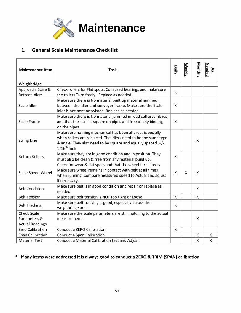
Maintenance
1. General Scale Maintenance Check list
Maintenance Item Task D
aily
Weekly
Mo
nth
ly
As
Need
ed
Weighbridge
Approach, Scale & Retreat Idlers
Check rollers for Flat spots, Collapsed bearings and make sure the rollers Turn freely. Replace as needed
X
Scale Idler Make sure there is No material built up material jammed between the Idler and conveyor frame. Make sure the Scale idler is not bent or twisted. Replace as needed
X
Scale Frame Make sure there is No material jammed in load cell assemblies and that the scale is square on pipes and free of any binding on the pipes.
X
String Line
Make sure nothing mechanical has been altered. Especially when rollers are replaced. The idlers need to be the same type & angle. They also need to be square and equally spaced. +/- 1/16th Inch
X
Return Rollers Make sure they are in good condition and in position. They must also be clean & free from any material build up.
X
Scale Speed Wheel
Check for wear & flat spots and that the wheel turns freely. Make sure wheel remains in contact with belt at all times when running, Compare measured speed to Actual and adjust if necessary.
X X X
Belt Condition Make sure belt is in good condition and repair or replace as needed.
X
Belt Tension Make sure belt tension is NOT too tight or Loose. X X
Belt Tracking Make sure belt tracking is good, especially across the weighbridge area.
X
Check Scale Parameters & Actual Readings
Make sure the scale parameters are still matching to the actual measurements. X
Zero Calibration Conduct a ZERO Calibration X
Span Calibration Conduct a Span Calibration X X
Material Test Conduct a Material Calibration test and Adjust. X X
* If any items were addressed it is always good to conduct a ZERO & TRIM (SPAN) calibration

58
2. Routine Calibration and Verification Procudures
Routine calibrations consist of conducting:
ZERO Calibration 2-3 times / day or when needed based on stability of empty belt
weight over time
Span Calibration with test weights (when needed)
Material tests (when needed)
3. Physical & Mathematical Verification using Tests Weights
A. Pre checks / measurements
Measure ACTUAL belt speed. (be very accurate) meters/minute ____ m/min (ft/m)
Measure ACTUAL Weigh Span (be very accurate) meters or feet ______m or Ft
Measure ACTUAL Test weight on a LAB scale (be very accurate)kg or pounds ____Kg or Lbs.
How to Calculate Actual Belt Speed without a Tachometer Using a Stop Watch
A. Mark the belt at 1 point
B. On the conveyor mark 2 reference points A & B (20 meters apart) 20 meters
C. Start and run the belt empty
D. Time in seconds how long it takes the mark from point A to B. D = _____seconds
E. Time in seconds how long it takes the mark on the belt to do 1 rev. E = ______seconds
F. Used if you cannot see the belt from where the integrator is mounted for “set Zero”
Calculate belt speed by using the following formula
Belt Speed (m/min) = 20 meters . Time from A to B in seconds X 60 Seconds
B. Verify the scale Span & Test weight setting reads the same as Actual Measured in #1
Make sure the weigh span matches ACTUAL measured span.
Make sure the Test weight matches ACTUAL measured Test Weight.
Correct if needed.
Press weight rate.
C. Verify the scale belt speed reads the same as Actual Measured belt speed in #1
Make sure Belt speed is the same as Measured belt speed in #1
If belt speed is not the same then the pulley diameter may be manually adjusted to make
the speed match.
D. Calculate the TPH using ACTUAL MEASUREMENTS from conveyor
This formula is the same for Feet (ft). Replace Meters with Ft. measurement.

59
USE MEASURED VALUES FROM STEP #1
USE the following formula to calculate what rate you should be running after calibration.
Example:
Test weight = 100kg Scale
Belt speed = 91 m/m
Idler spacing is 1.2m 0.8m total weigh span = 2m
Therefore Weigh span = 2m
100 (kg) / 1 (m) X 60 minutes X 91 (m/min) / 1000 = 546 MTPH CALCULATED Rate
E. Perform a ZERO Calibration
Make sure the belt is EMPTY and has NO Test weights or bar on the scale.
Conduct a ZERO calibration per the service manual.
F. Perform a Calibration with Test Weights
Install weights with bar on scale and run belt empty with no material.
Conduct a Test Weight calibration per the service manual.
G. Compare TPH after check span to #4 CALCULATED RATE TPH.
If the rate on the scale matches the CALCULATED RATE then your scale should be close. This is a
mathematical verification and should get the scale calibration +/- 2%. A material test with a certified
scale is the best method of scale verification.
If it does not match then a span number adjustment is necessary (see below). This is common as this will
compensate in conveyor issues, slippage and conveyor angle.
Test Weight in (kilograms)
(½ X Weigh Span) in (meters) X 60 Belt Speed (meters per Minute)
1000
Test Weight in (pounds)
(½ X Weigh Span) in (feett) X 60 Belt Speed (feet per minute)
2000
METRIC
ENGLISH

60
General Specifications
Electrical:
Input Power to Belt-Way Integrator: 12-30 VDC - 24 VDC 2.25A nominal.
AC Power option: 90-265 VAC 50/60 Hz.
Use of the factory supplied power supply is recommended.
Conformance to local electrical codes is recommended.
AC control power over current protection with isolated circuit, and disconnect point such as
a breaker or switch box, is recommended.
Environmental:
Temperature: Normal operating range -15 to +60 degrees C. Please consult the factory if the
unit will be operated outside the stated range. Wide temperature range components may be
required. Humidity: The unit is suitable for outdoor use. Altitude: The unit is suitable for use to elevation of 2000m.
Maintenence and Replacement Parts:
The integrator may be cleaned using a mild cleaner and soft rag. The load cell assemblies, speed sensor, and angle may be wached with low pressure water
and mild soap. The scale components should be periodically inspected for damage. All cables should be inspected for pinches or breaks Load cells should be visually checked for material build -up. The speed sensor wheel shoud be checked for wear. Replacement parts are available from local dealers or the factory. Replacement fuses may be purchased locally or from the factory The following fuses are required for operation:
Integrator board: 1.25 A, 125 V Fast, SMD
Sensor board: 800 mA, 250 VAC Slo Blo 5x20mm
I/O board: 200 mA, 125V, Fast, SMD
SMPS board (power supply): 3A, 250 VAC, Ultra Fast, 5x20mm
Terminal Board: 7A, 125VAC, 125VDC, Fast, SMD
Terminal Board: 1.25 A, 125V, Fast, SMD

61
Product Warranty Belt-Way Scales, Inc. ("Belt-Way"), warrants its products only on the terms contained herein.
No one has the right or authority to assume or create any obligation or responsibility,
express or implied, on behalf of or in the name of Belt-Way Scales, Inc., or to bind Belt-Way
Scales, Inc., in any manner whatsoever.
Products manufactured by Belt-Way are warranted to be free of manufacturing defects for a
one year period after the original date of purchase. Belt-Way's liability here under is
conditioned on dealer, or in the event of a direct sale to a first-end user (then on first-end user)
giving notice in writing to Belt-Way of any alleged defect. Such notice must be given immediately
upon the discovery of such alleged defect.
If, within the warranty period, any machinery or parts shall be proved to the satisfaction of Belt-
Way to be defective, the defective item shall be replaced or, at Belt-Way's option, repaired at
Belt-Way's factory.
The right to have defective machinery or parts, repaired or replaced as set forth above, shall
constitute the dealer or first-end user's sole and exclusive remedy. No warranty shall apply to
machinery, parts or accessories which have been furnished, repaired or altered by others so
as (in the opinion of Belt-Way) to have affected the same adversely. Belt-Way cannot and does
not warrant or represent that machinery or parts furnished by it will handle specific materials or
will produce specific results from such materials.
This warranty does not include damage to the product resulting from accident, misuse, improper
installation or operation. If a component should become defective within the warranty period, we
will repair or replace it free of charge at our option. Defective components must be returned freight
prepaid to Belt-Way or to an authorized Belt-Way service center.
Complete products included with our system that are not manufactured by Belt-Way such as
printers, remote displays, etc. are warranted to the extent that they are warranted to us.
The customer's sole remedy shall be such repair or replacement as is expressly provided above, and
we shall in no event be liable for any incidental or consequential damages arising out of the use or
inability to use this product for any purpose whatsoever.
Some states do not allow the exclusion or limitation of incidental or consequential damages, so the
above limitation or exclusion may not apply to you.
This warranty gives you specific legal rights. You may also have other rights which vary from state to
state. For products purchased outside the United States, see your distributor for warranty.
62
Limitations and Disclaimer
BELT-WAY SCALES, INC. MAKES NO REPRESENTATION OR WARRANTY OF ANY OTHER KIND, EXPRESS OR
IMPLIED, WITH RESPECT TO THE PRODUCTS, WHETHER AS TO MERCHANTABILITY, FITNESS FOR A
PARTICULAR PURPOSE OR ANY OTHER MATTER, ANY SUCH WARRANTIES BEING HEREBY EXPRESSLY
EXCLUDED. BELT-WAY SCALES, INC. DOES NOT AUTHORIZE ANYONE TO MAKE ANY OTHER WARRANTY
EXCEPT AS STATED HEREIN.
Exclusion of Consequential Damages
BELT-WAY SCALES, INC. SHALL IN NO EVENT BE RESPONSIBLE FOR SPECIAL, INCIDENTAL OR CONSEQUENTIAL
DAMAGES CAUSED BY ANY PRODUCT SOLD HEREUNDER, WHETHER ON THEORIES OF BREACH OF EXPRESS
OR IMPLIED WARRANTIES UNDER THE UNIFORM COMMERCIAL CODE, STRICT LIABILITY, NEGLIGENCE OR ANY
OTHER LEGAL THEORY REGARDLESS OF WHETHER THE LOSS RESULTED FROM ANY GENERAL OR
PARTICULAR REQUIREMENT OR NEED WHICH BELT-WAY SCALES, INC. KNEW ABOUT OR HAD REASON TO KNOW
ABOUT AT THE TIME OF THE SALE OF SUCH PRODUCTS.
BELT-WAY is a registered trademark of Belt-Way Scales, Inc.
FLO-WAY is a registered trademark of Belt-Way Scales, Inc.
Covered by U.S. PATENT 5,696,354