Embed Size (px)
Citation preview

1
CONVERSION KIT040-00006-01

2
BEFORE YOU BEGIN:
DRIFT CONVERSION KIT TO BE INSTALLED BY QUALIFIED SERVICE PERSONAL ONLY.
BEFORE STARTING, UNPLUG THE AC LINE CORD TO REMOVE ALL POWER.
A SAFE, DRY AND LIGHTED WORK SPACE WILL BE REQUIRED.
DO NOT DISABLE, REMOVE OR MODIFY ANY SAFETY FUNCTIONS OR DEVICES IN THE CABINET OR THE DRIFT CONVERSION KIT.
THE CABINET AND THE NEW DRIFT CONVERSION KIT CONTAIN SENSITIVE ELECTRONIC DEVICES. PROPER ESD PRACTICES NEED TO BE FOLLOWED.
THE COMPUTER DEFAULT POWER SETTING IS 110VAC.
CRUSIN USA, CRUSIN WORLD, CRUSIN EXOTICA, AND OFFROAD CHALLENGE IS COPYRIGHT MIDWAY GAMES, LLC.CALIFORNIA SPEED IS COPYRIGHT ATARI GAMES.DRIFT FAST AND FURIOUS IS COPYRIGHT RAW THRILLS, INC.FAST AND FURIOUS IS COPYRIGHT UNIVERSIAL, LLC.

3
RECOMMENDED TOOLS LIST:
CORDLESS DRILL1/2” DRILLBIT1/4” HEX-HEAD NUT DRIVERPHILIPS SCREWDRIVERFLATBLADE SCREWDRIVER
OPTIONAL:JIGSAW OR KEY-HOLE SAWDIGITAL VOLT METER(DVM)

4EXISTING GAME ELECTRONICS ASSEMBLY IS TO BE REMOVED.(ASSEMBLY PICTURED MAY BE DIFFERENT)

5
UNPLUG ALL THE CABINET CABLES
IN THE GAME. THIS IS THE POINT
OF WHERE THE MAIN HARNESS
CONNECTS TO THE CABINET
CABLES WITH A Z-HEADER. LEAVE
THE Z-HEADER CONNECTED TO
THE CABINET CABLE.
UNPLUG THE FOLLOWING CABLES:
DASH SWITCHESDASH LAMPSSHIFTERKEYPADSTEERING MECHSPEAKERSVIDEOPEDAL MECHANISMSTEERING TRANSFORMERCOIN BOXTEST SWITCH ASSEMBLYSEAT AUDIO

6
ONCE ALL THE CABINET CABLES
ARE DISCONNECTED FROM THE
MAIN ELECTRONICS ASSEMBLY,
REMOVE THE TWO(2) SCREWS
HOLDING THE MAIN ASSEMBLY
IN THE CABINET. CAREFULLY
REMOVE THE ASSEMBLY FROM
THE CABINET.
PICTURE SHOWS THE GAME CABINET WITH THE
ELECTRONIC ASSEMBLY REMOVED.

7
MOUNTED ON THE BOTTOM OF THE GAME IS A POWER SUPPLY THAT WILL NO
LONGER BE USED. UNPLUG THE AC LINE CORD FROM THE POWER SUPPLY
AND FREE IT FROM ANY CABLE CLAMPS. THIS AC POWER CORD WILL BE USED
TO POWER YOUR NEW DELL COMPUTER. IF YOU ARE CONVERTING A CRUSIN'
USA YOU WILL NOT HAVE THIS, FOR THE POWER SUPPLY IS MOUNTED TO THE
ELECTRONIC ASSEMBLY. A CABLE IS PROVIDED THAT WILL BE USED TO
POWER THE DELL COMPUTER.

8
BEFORE INSTALLING THE NEW
ELECTRONIC ASSEMBLY YOU MAY
HAVE TO RE-LOCATE SOME
CABLE CLAMPS AND CABINET
CABLES.

9
PROPER CLEARANCE FOR THE NEW ELECTRONIC ASSEMBLY IS REQUIRED. THE
POWER SUPPLY ASSEMBLY MOUNTED ON THE BOTTOM OF THE CABINET MAY
NEED TO BE MOVED OVER TO THE LEFT. FOUR (4) SCREWS ATTACH THE
ASSEMBLY TO THE BOTTOM OF THE CABINET. DO NOT REMOVE THE POWER
SUPPLY ASSEMBLY IF IT IS USED FOR AC POWER DISTRIBUTION.

10
MOUNT THE NEW ELECTRONIC ASSEMBLY. ONE CAN USE THE TOP METAL BEND AS A GRIP/HANDLE. DO NOT HOLD ANY PORTION OF THE CIRCUIT BOARDS. LOCATE THE TOP OF THE METAL PLATE JUST BELOW THE T-NUTS OF THE CABINET. MAKE SURE THAT THE METAL PLATE LIES FLAT TO THE CABINET. SECURE THE ASSEMBLY WITH THE PROVIDED SCREWS. THERE IS SIX(6) HOLES IN THE PLATE FOR THE SCREWS.

11
SET DIP SWITCH BANK 2 THAT IS PRESENT ON THE I/O
BOARD TO MATCH THE GAME CABINET. SOMETIMES
ONE NEEDS TO USE MANUAL MODE IN ORDER TO
ACCOMADATE NON-STANDARD OPTIONS THAT MAY BE
PRESENT IN YOUR GAME CABINET.
DIP S2 - LOCATED ON THE I/O BOARD
8765 4321
--------------
0000 0000 CRUSIN USA
0000 0001 CRUSIN WORLD
0000 0100 OFFROAD CHALLENGE
0000 0110 CALIFORNIA SPEED
1X00 1XXX CRUSIN EXOTICA
1XXX XXXX MANUAL MODE
11XX XXXX SWITCH POLARITY REV.
1X00 XXXX EGA MONITOR
1X01 XXXX EGA2 MONITOR
1X10 XXXX VGA MONITOR
1X11 XXXX CGA MONITOR
1XXX 0XXX NO KEYPAD
1XXX 1XXX KEYPAD
X : DON'T CARE
EGA2 : MAY OFFER BETTER FONT
RESOLUTION, DEPENDING ON THE
MONITOR.

12
BEGIN TO CONNECT THE NEW JAMMA CABLE TO THE CABINET CABLES. LABELS
ON THE NEW JAMMA CABLE WILL HELP WITH THIS PROCESS. SOME CONNECTIONS
HAVE TWO POSSIBLE CONNECTORS. CHOOSE THE ONE THAT FITS YOUR
APPLICATION. LEAVE THE PC CONNECTORS UN-CONNECTED AT THIS TIME.

13
THERE IS A SHORT ADAPTER CABLE THAT IS PRESENT ON THE LAMP AND
SWITCH PORTION OF THE HARNESS. THIS ADAPTER IS FOR CRUSIN EXOTICA
ONLY. OTHERWISE THE ADAPTER CAN BE REMOVED. IF A KEYPAD IS
PRESENT, CONNECT THE NEW JAMMA HARNESS KEYPAD CONNECTOR
DIRECTLY TO THE KEYPAD.
EXOTICA LAMP/SWITCH ADAPTER KEYPAD

14
THE BOTTOM PC SHELF CAN BE INSTALLED. THIS PIECE WILL SIT ON THE WOOD CLEATS THAT THE OLD ELECTRONIC GAME ASSEMBLY SAT ON. METAL BRACKETS ARE PRE-INSTALLED ON THE WOOD PLATE. PLACE THE WOOD PIECE IN THE CABINET AND SECURE THE METAL BRACKETS TO THE CABINET.

15
IN SOME CASES THE BRACKET WILL GET ATTACHED TO THE SIDE OF THE CABINET...
OTHER TIMES IT IS ATTACHED TO A WOOD CLEAT. THE METAL BRACKET HAS SIX(6) HOLES FOR INCREASED MOUNTING FLEXIBILITY.

16
PLACE THE DELL PC ON THE BOTTOM SHELF. THE COMPUTER SHOULD BE
PLACED IN THE CLEATS ON THE LOWER WOOD MOUNTING PLATE. NOTICE THE
POSITION OF THE DELL LOGO ON THE SIDE OF THE COMPUTER. ENSURE THAT
THE COMPUTER IS SITTING LEVEL.

17
INTO THE USB PORTS, CONNECT THE USB FLASH-DRIVE
AND THE USB SECURITY DONGLE.

18
CONNECT THE CABLES TO THE PC. VERIFY THE INPUT VOLTAGE SETTING
SWITCH OF THE PC. THE DEFAULT IS 110VAC.

19
PLACE THE TOP PC SHELF ATOP THE COMPUTER AND SECURE THE METAL
BRACKETS TO THE CABINET. THE WOOD CLEATS OF THE TOP PC SHELF
SHOULD BE IN A DOWN POSITION SO AS THEY HOLD THE COMPUTER
SECURELY IN PLACE.

20
USING THE FAN TEMPLATE, CUT A HOLE IN THE BACK DOOR OF THE CABINET.
THE FAN ASSEMBLY IS MOUNTED TO THE DOOR FROM THE OUTSIDE. FOLLOW
THE DIRECTIONS ON THE TEMPLATE TO PROPERLY LOCATE WHERE THE HOLE
SHOULD BE CUT. FOR LONG, RELIABLE OPERATION OF THE GAME IT IS
IMPORTANT THAT THE FAN IS INSTALLED.
OUTSIDE VIEW
INSIDE VIEW

21
THE CONNECTOR FOR THE
FAN PLUGS INTO THE 5-PIN
CONNECTOR THAT IS
PRESENT ON THE FUSE
BOARD. VERIFY THAT IT IS
CONNECTED.

22
DON'T FORGET THE ARTWORK!

23
ONCE THE KIT IS INSTALLED, CONNECT THE EXTERNAL AC LINE CORD TO THE
CABINET AND TURN-ON THE POWER. AT THIS TIME THE GAME WILL GO THROUGH IT'S
FIRST-BOOT PROCESS. THIS MAY HAVE ALREADY OCCURED AT THE FACTORY. THE
FIRST-BOOT TAKES ABOUT 20 MINUTES. BECAUSE OF THE DEFAULT VIDEO MODE OF
COMPUTER YOU WILL NOT BE ABLE TO READ THE INFORMATION ON THE SCREEN.
ONCE THE GAME APPLICATION STARTS, THE VIDEO MODE WILL BE ADJUSTED.
REMEMBER THE VIDEO MODE IS DETERMINED ACCORDING TO THE DIP 2 SWITCH
CONFIGURATION. DIP 2 SWITCH IS LOCATED ON THE I/O BOARD.
WARNING: ONCE A FLASH DRIVE HAS BEEN BOOTED ON A COMPUTER, THE FLASH DRIVE CANNOT BE MOVED TO ANOTHER MACHINE. THE GAME WILL NOT FUNCTION PROPERLY. IF YOU NEED TO MOVE THE DRIVE OR FEEL THAT THE DRIVE IS CORRUPT, ONE CAN REFORMAT THE FLASH DRIVE BY USING THE RESTORE CD THAT IS PROVIDED.

24
IT IS RECOMMENDED THAT ONCE THE GAME IS RUNNING ONE SHOULD ENTER
THE TEST MENU AND VERIFY THE GAME IS FUNCTIONAL. THIS WOULD INCLUDE
TESTING THE SWITCHES, LAMPS, KEYPAD, SHIFTER, AND THE AUDIO.
CALIBRATION OF THE GAME IS ALSO RECOMMENDED AT THIS TIME.
WARNING: CHECK AND MAKE SURE THAT THE FAN MOUNTED ON THE BACKDOOR IS WORKING.
ATTENTION!: THE DRIFT KIT HAS TWO(2) FUSES PRESENT ON THE FUSE/WATCHDOG BOARD. THERE IS ALSO A FUSE ON THE STEERING MOTOR CONTROLLER. FOR CONTINUED PROTECTION REPLACE A FUSE WITH A IDENTICAL UL RATED FUSE.

25
BIOS SETTINGS FOR THE PC ARE SET AT THE FACTORY.-System +Boot Sequence 1. CD/DVD/CD-RW Drive 2. USB-ZIP 3. USB-Device 4. Hard Drive 5. USB-FDD 6. USB-CDROM 7. Non-Integrated NIC 8. Diskette Drive + HDD Boot Sequence [don't care] -Drives +Diskette Drive: USB +Drive 0: SATA-0: ON +Drive 1: SATA-1: ON +SMART Reporting: OFF -Onboard Devices +Integrated NIC : ON +Integrated Audio : ON +USB Controller : ON +Rear Triple USB : ON +Real Dual USB : ON +Front USB : ON +LPT Port Mode : EPP +LPT Port Address : 378h +Serial Port #1 : COM1
-Video +Primary Video : Onboard/Card +Video Memory Size : 16MB -Performance +HDD Acoustic Mode : Bypass
-Security +Admin Password: None +System Password : None +Drive 0 Password : None +Drive 1 Password : None +Password Changes : Unlocked +Chassis Intrusion : OFF +TPM Security: OFF +No Execute: OFF -Power Management +AC Recovery: ON +Auto Power On: OFF +Low Power Mode: OFF +Remote Wake Up: OFF +Cool and Quiet: OFF +Suspend mode: S3
-Maintenance +ASF Mode: OFF +Fast Boot: On
-POST Behavior +Numlock Key: On +Post Hotkeys : Setup & Boot Menu +Keyboard Errors: Do Not Report

26
Game Fails To Power-upThe game will be in this failure mode when either the main AC power has failed, been disconnected, or the computer has failed to turn-on. The computer provides +5VDC and +12VDC for the system. Turning on of the computer is controlled by the FUSE/WD board, p/n 500-00016-01.
1.Verify the cabinet main power switch is on.2.Verify the AC line cord is plugged into a functional AC outlet.3.Verify the AC outlet is the correct voltage for the game.4.Verify the computer is set to the correct voltage. There is a voltage switch on the PC that needs to be set correctly. If this switch is set
incorrectly and the game has been powered, damage to the computer may have occurred.5.Verify the main AC power fuse for the cabinet. If a fused failed, examine the game for a fault condition and repair the condition before replacing
the fuse. For continued protection, replace the fuse with identical UL rated fuse. 6.Verify the fuses on the FUSE / WD board, p/n 500-00016-01. These fuses protect the +5VDC and +12VDC power rails. If a fused failed,
examine for a fault condition and repair the condition before replacing the fuse. For continued protection, replace the fuse with identical UL rated fuse.
7.Look for cable connectors that are loose or not connected.
“NO VIDEO” Message On The Video MonitorThis message is present when the video monitor is powered but the video monitor has no valid video signal.
1.Verify the PC is functioning.2. Look for cable connectors that are loose or not connected. Check that the VGA cable is connected into the VGA connector labled '1' at the PC.
No Video On The Video MonitorThis failure is when either the game is not powered, the monitor is not powered, the monitor is not correctly adjusted or the video monitor has failed.
1.Verify the game has powered-up. 2.Verify the cable connectors, paying close attention to the power and video signal cables of the video monitor.3.Verify the video monitor has AC power.4.Verify the contrast and brightness settings of the monitor. Make sure they are not set too low.
WARNING. Remove all power and disconnect AC line cord before servicing! Service performed by qualified service technician only. With power on do not connect or disconnect cables or connectors, damage will occur. Hazardous voltages are present even with the game off and unplugged from AC voltage. Use extreme caution.
Troubleshooting:

27
Game Has No SoundIf the game is running and there is no sound.
1.Verify that the audio levels are set to acceptable levels. This can be done through the Diagnostic Menu System.2.Verify the cable connections. Ensure that the audio cable from the computer is connected to the I/O board.3.Verify the speaker cable is connected.4.Verify the fuses on the FUSE / WD board, p/n 500-00016-01. These fuses protect the +5v and +12v. If a fused failed, examine for a fault
condition and repair the condition before replacing the fuse. Replace fuse with identical UL rated fuse.5.Verify the I/O board has power.
Monitor Displays 'CONNECT I/O'If the computer is unable to communicate with the I/O board, the 'Connect I/O' message will be displayed in the video display.
1.Verify that the I/O board has power. Check the fuses on the FUSE / WD board, p/n 500-00016-01.2.Verify the cable connections. Verify the USB cable that connects the I/O board to the computer is securely attached.3.Power-cycle the game.
Monitor Displays 'INSERT DONGLE'This message indicates that the computer is unable to communicate with the security dongle that is located on the back of the computer.
1.Verify that the security dongle is attached to a USB port of the computer.
Game Play is Slow, Freezes, or ResetsNumerous items can cause game play to exhibit freezing or slow play. Typical failure modes include excessive heat, corrupt drive, or failing hardware.
1.Verify that the security dongle is attached to a USB port of the computer.2.Verify cable connections. Verify the USB cable that connects the I/O board to the computer is securely attached.3.Verify that the game is not running excessively hot. Verify that the cooling fan on the back door is running and not obstructed. The back of the
cabinet must be at least one foot away from a wall. 4.Verify that the computer is not running excessively hot. Verify that the computers cooling fans are running.5.Verify the drive. This can be done via the Operators Menu. The drive can be re-imaged, by inserting the CD that was included.6.Verify that the games +5VDC +12VDC power rails are within +/- 5% tolerance.
Distorted Video On The Video MonitorVideo resolution of the computer is not compatible with the monitor.
1. Adjust the video output signal of the computer by setting DIP SWITCH2, located on the I/O board.
28
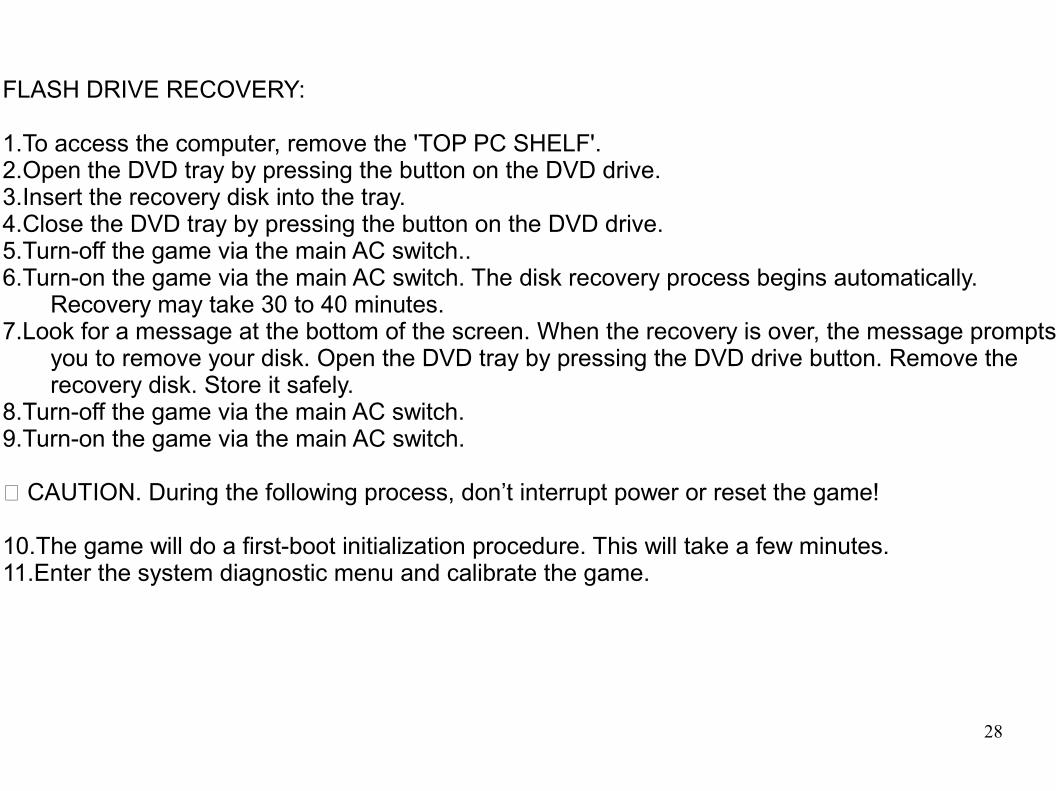
FLASH DRIVE RECOVERY:
1.To access the computer, remove the 'TOP PC SHELF'.2.Open the DVD tray by pressing the button on the DVD drive.3.Insert the recovery disk into the tray. 4.Close the DVD tray by pressing the button on the DVD drive.5.Turn-off the game via the main AC switch..6.Turn-on the game via the main AC switch. The disk recovery process begins automatically.
Recovery may take 30 to 40 minutes.7.Look for a message at the bottom of the screen. When the recovery is over, the message prompts
you to remove your disk. Open the DVD tray by pressing the DVD drive button. Remove the recovery disk. Store it safely.
8.Turn-off the game via the main AC switch.9.Turn-on the game via the main AC switch.
CAUTION. During the following process, don’t interrupt power or reset the game! 10.The game will do a first-boot initialization procedure. This will take a few minutes.11.Enter the system diagnostic menu and calibrate the game.

29
FUNCTION WIRE COLOR PIN PIN WIRE COLOR FUNCTIONGROUND BLK 1 A BLK GROUND
2 B5 VOLTS RED 3 C
4 D5 E
12 VOLTS ORANGE 6 F7 H
COIN METER BROWN YELLOW 8 J9 K
SPEAKER (+) RED GREY 10 L BROWN GRAY SPEAKER (-)SPEAKER (+) RED WHITE 11 M BROWN WHITE SPEAKER (-)RGB RED YELLOW RED 12 N YELLOW GREEN RGB GREENRGB BLUE YELLOW BLUE 13 P YELLOW WHITE RGB SYNCHRGB GROUND YELLOW BLACK 14 R WHITE GRAY SERVICETEST BLACK BLUE 15 SCOIN 1 BLACK BROWN 16 T BLACK RED COIN 2START WHITE 17 U VIEW1 WHITE BLACK 18 V GREEN BLACK 2nd GEARVIEW2 WHITE BROWN 19 W GREEN BROWN 3rd GEARVIEW3 WHITE RED 20 X GREEN RED 4th GEARTUNES WHITE ORANGE 21 Y GREEN ORANGE 5th GEARKEYPAD COL 0 BLUE YELLOW 22 ZKEYPAD COL 1 BLUE GREEN 23 a
JAMMA I/O BOARD CONNECTION CHART
COMPONENT SIDE SOLDER SIDE

30
I/O BOARD CONNECTORS
P1 - I/O BOARD P3 - I/O BOARD
FUNCTION WIRE COLOR PIN FUNCTION WIRE COLOR PIN1 GROUND BLACK 1
KEY 2 2KEYPAD ROW 0 BLUE BLACK 3 3KEYPAD ROW 1 BLUE BROWN 4 4KEYPAD ROW 2 BLUE ORG 5 KEY 5KEYPAD ROW 3 BLUE RED 6 6
DBV SIGNAL WHITE BLACK 7VOLUME DOWN ORANGE RED 8VOLUEM UP ORANGE GREEN 9
1011
P6- I/O BOARD P7- I/0 BOARDFUNCTION WIRE COLOR PIN FUNCTION WIRE COLOR PIN
1 5 VOLTS RED WHITE 1VIEW3 LAMP VIOLET BLACK 2 5 VOLTS RED BLACK 2VIEW2 LAMP VIOLET BROWN 3 KEY 3KEY 4 STEERING POT. WHTE 4VIEW1 LAMP VIOLET RED 5 5START LAMP VIOLET ORANGE 6 BRAKE BROWN 6

31
SUBWOOFER AMP/WHEEL DRIVER BOARD CONNECTION CHART
MOTOR OUT POWER INFUNCTION WIRE COLOR PIN FUNCTION WIRE COLOR PINMOTOR(+) VOLTAGE RED WHITE 1 12 VOLTS ORANGE 1MOTOR(-) VOLTAGE BLACK WHITE 2 GROUND BLACK 2
3
WOOFER OUT 18VAC INPUTFUNCTION WIRE COLOR PIN FUNCTION WIRE COLOR PINSUBWOOFER(+) RED YELLOW 1 18 VOLTS AC BLUE BLACK 1SUBWOOFER(-) BROWN YELLOW 2 18 VOLTS AC BLUE 2
USB WATCHDOG/FUSE PCB CONNECTION CHART
P2 P3FUNCTION WIRE COLOR PIN FUNCTION WIRE COLOR PIN5 VOLT INPUT RED WHITE 1 1
2 23 DIGITAL GROUND GREY 3
12VOLT INPUT ORANGE WHITE 4 POWER ON GREEN 45 5 VOLT STDBY SWITCHED VIOLET ORANGE 56 5 VOLT STDBY VIOLET GREEN 6
GROUND BLACK 7GROUND BLACK 8
P6 P9FUNCTION WIRE COLOR PIN FUNCTION WIRE COLOR PIN12 VOLTS FUSED ORANGE 1 5 VOLTS FUSED RED 112 VOLTS FUSED ORANGE 2 5 VOLTS FUSED RED 212 VOLTS FUSED ORANGE 3 5 VOLTS FUSED RED 3GROUND BLACK 4 5 VOLTS FUSED RED 4

32