Embed Size (px)
Citation preview
313
FIBERSENSORS
LASERSENSORS
PHOTOELECTRICSENSORS
MICROPHOTOELECTRIC
SENSORS
AREASENSORS
SAFETY LIGHT CURTAINS /
SAFETY COMPONENTSPRESSURE /
FLOWSENSORS
INDUCTIVEPROXIMITY
SENSORS
PARTICULARUSE SENSORS
SENSOROPTIONS
SIMPLEWIRE-SAVING
UNITS
WIRE-SAVING SYSTEMS
MEASUREMENTSENSORS
STATIC CONTROL DEVICES
LASERMARKERS
PLC
HUMAN MACHINE INTERFACES
ENERGY MANAGEMENT
SOLUTIONS
FA COMPONENTS
MACHINE VISION SYSTEMS
UV CURING SYSTEMS
Selection Guide
Amplifier Built-in
Power Supply Built-in
Amplifier-separated
EX-Z
CX-400
CY-100
EX-10
EX-20
EX-30
EX-40
CX-440
EQ-30
EQ-500
MQ-W
RX-LS200
RX
RT-610
Related Information
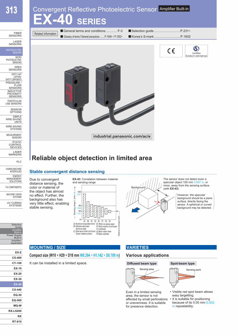
EX-40 SERIES
Reliable object detection in limited area
Stable convergent distance sensingDue to convergent distance sensing, the color or material of the object has almost no effect. Further, the background also has very little effect, enabling stable sensing.
0
501.969
1003.937
301.181
Aluminum-evaporated mirrorStainless steel plateAluminum plateGlass epoxy printed circuit board(Green masked surface)
Sen
sing
rang
e L
(mm
in)
White non-glossy paperWhite ceramic circuit boardCardboardBlack rubber sheetBlack substrate Di
stanc
e to c
onve
rgen
t poin
t
AA
B
B
C
C
DD
E
E
F
F
G
G
H
H
EX-43: Correlation between materialand sensing range
Background
The sensor does not detect even a specular object 100 mm 3.937 in, or more, away from the sensing surface. (with EX-43)
However, the specular background should be a plane surface, directly facing the sensor. A spherical or curved background may be detected.
Compact size (W10 × H29 × D18 mm W0.394 × H1.142 × D0.709 in) It can be installed in a limited space.
MOUNTING / SIZE
Various applications
Even in a limited sensing area, the sensor is not affected by small perforations or unevenness. It is suitable for presence detection.
VARIETIES
Diffused beam typeSensing area
Spot-beam type
Sensing point
• Visible red spot beam allows easy targetting.
• It is suitable for positioning because of its 0.05 mm 0.002 in repeatability.
Convergent Reflective Photoelectric Sensor Amplifier Built-in
General terms and conditions ............. F-3 Selection guide ............................. P.231~
Glossary of terms / General precautions .....P.1549~ / P.1552~ Korea’s S-mark ............................. P.1602
Certified(Excluding 5 m cable length type)
industrial.panasonic.com/ac/e
Convergent Reflective Photoelectric Sensor EX-40 SERIES 314
FIBERSENSORS
LASERSENSORS
PHOTO-ELECTRICSENSORSMICROPHOTO-ELECTRICSENSORS
AREASENSORS
SAFETY LIGHT CURTAINS /SAFETY COMPONENTSPRESSURE / FLOWSENSORS
INDUCTIVEPROXIMITYSENSORS
PARTICULARUSE SENSORS
SENSOROPTIONS
SIMPLEWIRE-SAVINGUNITS
WIRE-SAVING SYSTEMS
MEASURE-MENTSENSORS
STATIC CONTROL DEVICES
LASERMARKERS
PLC
HUMAN MACHINE INTERFACES
ENERGY MANAGEMENT SOLUTIONS
FA COMPONENTS
MACHINE VISION SYSTEMS
UV CURING SYSTEMS
Selection GuideAmplifier Built-inPower Supply Built-inAmplifier-separated
EX-Z
CX-400
CY-100
EX-10
EX-20
EX-30
EX-40
CX-440
EQ-30
EQ-500
MQ-W
RX-LS200
RX
RT-610
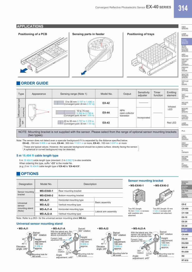
ORDER GUIDE
Type Appearance Sensing range (Note 1) Model No. Output Sensitivityadjuster
Timer function
Emitting element
Diffu
sed
beam
type 5 to 38 mm 0.197 to 1.496 in
(Convergent point: 20 mm 0.787 in) EX-42
NPNopen-collector transistor
–
–
Infrared LED
Long se
nsing ra
nge
10 to 70 mm0.394 to 2.756 in
(Convergent point: 40 mm 1.575 in)EX-44
Incorporated
Spot-
beam
typ
e 20 to 35 mm 0.787 to 1.378 in(Convergent point: 30 mm 1.181 in) EX-43 Red LED
APPLICATIONS
Positioning of a PCB Sensing parts in feeder Positioning of trays
Note: The sensor does not detect even a specular background if it is separated by the distance specified below.EX-42...150 mm 5.906 in or more, EX-44...300 mm 11.811 in or more, EX-43...100 mm 3.937 in or more
NOTE: Mounting bracket is not supplied with the sensor. Please select from the range of optional sensor mounting brackets (two types).
5 m 16.404 ft cable length type5 m 16.404 ft cable length type (standard: 2 m 6.562 ft) is also available.When ordering this type, suffix “-C5” to the model No.(e.g.) 5 m 16.404 ft cable length type of EX-42 is “EX-42-C5”.
OPTIONS
Designation Model No. Description
Sensor mountingbracket
MS-EX40-1 Rear mounting bracket
MS-EX40-2 Bottom mounting bracket
Universal sensor mounting stand (Note)
MS-AJ1 Horizontal mounting typeBasic assembly
MS-AJ2 Vertical mounting type
MS-AJ1-A Horizontal mounting typeLateral arm assembly
MS-AJ2-A Vertical mounting type
Sensor mounting bracket• MS-EX40-1
Two M3 (length 16 mm 0.630 in) screws with washers are attached.
• MS-EX40-2
Two M3 (length 16 mm 0.630 in) screws with washers are attached.
Note: Refer to p.953~ for the universal sensor mounting stand MS-AJ.
Universal sensor mounting stand• MS-AJ1
45°
45°Elevationangle: ±45°
Heightadjustment:150 mm5.906 inapprox.
Swivel:360° rotation
Mounting hole forM6 screw
• MS-AJ1-A
45° 45° Angle adjustment: ±45°
Mounting hole for M6 screw
Height adjustment: 150 mm 5.906 in approx.
360° rotation
Swivel: 360° rotation With the lateral arm, the
sensor can sense from above a production line. Forward / back adjustment:130 mm 5.118 in
• MS-AJ2
45°
45°Elevationangle: ±45°
Mounting hole forM6 screw
Heightadjustment:150 mm5.906 inapprox.
Swivel:360° rotation
• MS-AJ2-A
360° rotation
45° 45°
adjustment: ±45°
Swivel: 360° rotation
Mounting hole for M6 screw
Height adjustment: 150 mm 5.906 in approx.
Angle
With the lateral arm, the sensor can sense from above a production line. Forward / back adjustment:130 mm 5.118 in
These are typical values. However, the specular background should be a plane surface, directly facing the sensor.A spherical or curved background may be detected.
315 Convergent Reflective Photoelectric Sensor EX-40 SERIES
FIBERSENSORS
LASERSENSORS
PHOTO-ELECTRICSENSORS
MICROPHOTO-
ELECTRICSENSORS
AREASENSORS
SAFETY LIGHT CURTAINS /
SAFETY COMPONENTSPRESSURE /
FLOWSENSORS
INDUCTIVEPROXIMITY
SENSORS
PARTICULARUSE
SENSORS
SENSOROPTIONS
SIMPLEWIRE-SAVING
UNITS
WIRE-SAVING SYSTEMS
MEASURE-MENT
SENSORS
STATIC CONTROL DEVICES
LASERMARKERS
PLC
HUMAN MACHINE
INTERFACES
ENERGY MANAGEMENT
SOLUTIONS
FA COMPONENTS
MACHINE VISION
SYSTEMS
UV CURING
SYSTEMS
Selection Guide
Amplifier Built-in
Power Supply Built-in
Amplifier-separated
EX-Z
CX-400
CY-100
EX-10
EX-20
EX-30
EX-40
CX-440
EQ-30
EQ-500
MQ-W
RX-LS200
RX
RT-610
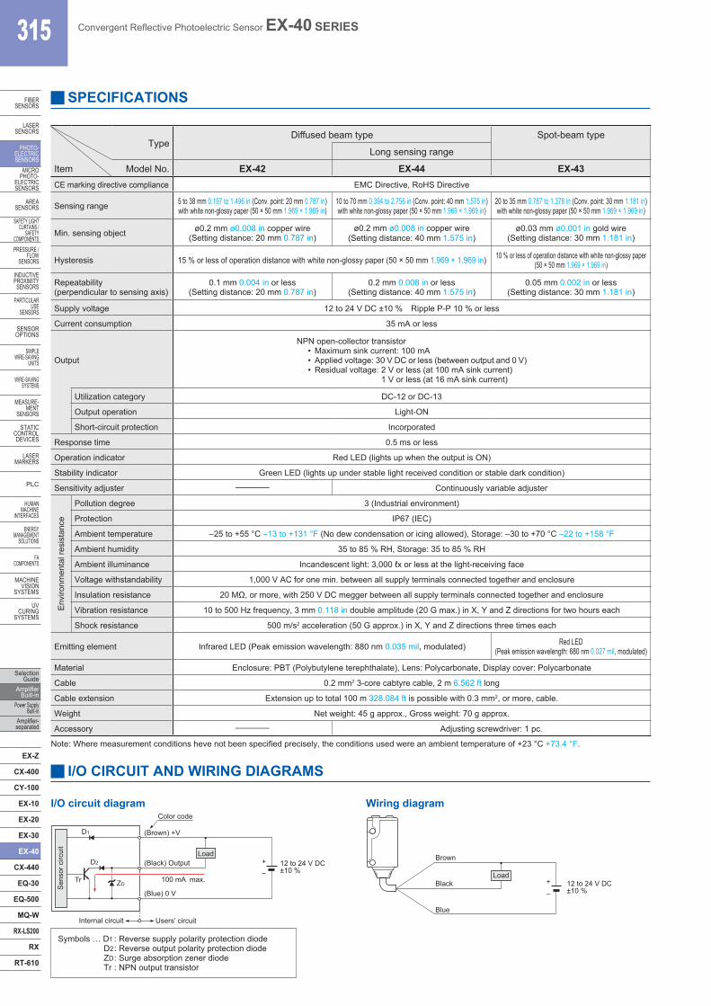
TypeDiffused beam type Spot-beam type
Long sensing range
Item Model No. EX-42 EX-44 EX-43CE marking directive compliance EMC Directive, RoHS Directive
Sensing range 5 to 38 mm 0.197 to 1.496 in (Conv. point: 20 mm 0.787 in) with white non-glossy paper (50 × 50 mm 1.969 × 1.969 in)
10 to 70 mm 0.394 to 2.756 in (Conv. point: 40 mm 1.575 in) with white non-glossy paper (50 × 50 mm 1.969 × 1.969 in)
20 to 35 mm 0.787 to 1.378 in (Conv. point: 30 mm 1.181 in) with white non-glossy paper (50 × 50 mm 1.969 × 1.969 in)
Min. sensing object ø0.2 mm ø0.008 in copper wire(Setting distance: 20 mm 0.787 in)
ø0.2 mm ø0.008 in copper wire(Setting distance: 40 mm 1.575 in)
ø0.03 mm ø0.001 in gold wire (Setting distance: 30 mm 1.181 in)
Hysteresis 15 % or less of operation distance with white non-glossy paper (50 × 50 mm 1.969 × 1.969 in) 10 % or less of operation distance with white non-glossy paper (50 × 50 mm 1.969 × 1.969 in)
Repeatability(perpendicular to sensing axis)
0.1 mm 0.004 in or less(Setting distance: 20 mm 0.787 in)
0.2 mm 0.008 in or less(Setting distance: 40 mm 1.575 in)
0.05 mm 0.002 in or less (Setting distance: 30 mm 1.181 in)
Supply voltage 12 to 24 V DC ±10 % Ripple P-P 10 % or less
Current consumption 35 mA or less
Output
NPN open-collector transistor• Maximum sink current: 100 mA• Applied voltage: 30 V DC or less (between output and 0 V)• Residual voltage: 2 V or less (at 100 mA sink current)
1 V or less (at 16 mA sink current)
Utilization category DC-12 or DC-13
Output operation Light-ON
Short-circuit protection Incorporated
Response time 0.5 ms or less
Operation indicator Red LED (lights up when the output is ON)
Stability indicator Green LED (lights up under stable light received condition or stable dark condition)
Sensitivity adjuster – Continuously variable adjuster
Envi
ronm
enta
l res
ista
nce
Pollution degree 3 (Industrial environment)
Protection IP67 (IEC)
Ambient temperature –25 to +55 °C –13 to +131 °F (No dew condensation or icing allowed), Storage: –30 to +70 °C –22 to +158 °F
Ambient humidity 35 to 85 % RH, Storage: 35 to 85 % RH
Ambient illuminance Incandescent light: 3,000 ℓx or less at the light-receiving face
Voltage withstandability 1,000 V AC for one min. between all supply terminals connected together and enclosure
Insulation resistance 20 MΩ, or more, with 250 V DC megger between all supply terminals connected together and enclosure
Vibration resistance 10 to 500 Hz frequency, 3 mm 0.118 in double amplitude (20 G max.) in X, Y and Z directions for two hours each
Shock resistance 500 m/s2 acceleration (50 G approx.) in X, Y and Z directions three times each
Emitting element Infrared LED (Peak emission wavelength: 880 nm 0.035 mil, modulated) Red LED (Peak emission wavelength: 680 nm 0.027 mil, modulated)
Material Enclosure: PBT (Polybutylene terephthalate), Lens: Polycarbonate, Display cover: Polycarbonate
Cable 0.2 mm2 3-core cabtyre cable, 2 m 6.562 ft long
Cable extension Extension up to total 100 m 328.084 ft is possible with 0.3 mm2, or more, cable.
Weight Net weight: 45 g approx., Gross weight: 70 g approx.
Accessory – Adjusting screwdriver: 1 pc.
SPECIFICATIONS
Note: Where measurement conditions heve not been specified precisely, the conditions used were an ambient temperature of +23 °C +73.4 °F.
I/O CIRCUIT AND WIRING DIAGRAMS
I/O circuit diagram Wiring diagram
Symbols … D1 : Reverse supply polarity protection diodeD2 : Reverse output polarity protection diodeZD : Surge absorption zener diodeTr : NPN output transistor
Sens
or c
ircui
t
Tr
(Brown) +V
(Black) Output
(Blue) 0 V
100 mA max.
Internal circuit Users’ circuit
Load 12 to 24 V DC±10 %–
+
Color code
ZD
D1
D2
12 to 24 V DC±10 %–
+ Load
Black
Brown
Blue
Convergent Reflective Photoelectric Sensor EX-40 SERIES 316
FIBERSENSORS
LASERSENSORS
PHOTO-ELECTRICSENSORSMICROPHOTO-ELECTRICSENSORS
AREASENSORS
SAFETY LIGHT CURTAINS /SAFETY COMPONENTSPRESSURE / FLOWSENSORS
INDUCTIVEPROXIMITYSENSORS
PARTICULARUSE SENSORS
SENSOROPTIONS
SIMPLEWIRE-SAVINGUNITS
WIRE-SAVING SYSTEMS
MEASURE-MENTSENSORS
STATIC CONTROL DEVICES
LASERMARKERS
PLC
HUMAN MACHINE INTERFACES
ENERGY MANAGEMENT SOLUTIONS
FA COMPONENTS
MACHINE VISION SYSTEMS
UV CURING SYSTEMS
Selection GuideAmplifier Built-inPower Supply Built-inAmplifier-separated
EX-Z
CX-400
CY-100
EX-10
EX-20
EX-30
EX-40
CX-440
EQ-30
EQ-500
MQ-W
RX-LS200
RX
RT-610
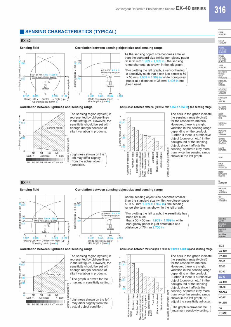
SENSING CHARACTERISTICS (TYPICAL)
EX-42
Sensing field Correlation between sensing object size and sensing range
As the sensing object size becomes smaller than the standard size (white non-glossy paper 50 × 50 mm 1.969 × 1.969 in), the sensing range shortens, as shown in the left graph.
Set
ting
dist
ance
L (m
m in
)
Dista
nce t
o con
verg
ent p
oint
(Down) Left
50 × 50 mm 1.969 × 1.969 inWhite non-glossy paper
401.575
40.157
40.157
20.079
20.079
00
200.787
L
Sensor
ℓ
Right (Up)Operating point ℓ (mm in)
Center
Sen
sing
rang
e L
(mm
in)
a × a mm a × a inWhite non-glossy paper
L
Sensor
401.575
200.787
401.575
602.362
803.150
200.787
0
White non-glossy paperside length a (mm in)
Correlation between lightness and sensing range Correlation between material (50 × 50 mm 1.969 × 1.969 in) and sensing range
The sensing region (typical) is represented by oblique lines in the left figure. However, the sensitivity should be set with enough margin because of slight variation in products.
The bars in the graph indicate the sensing range (typical) for the respective material. However, there is a slight variation in the sensing range depending on the product. Further, if there is a reflective object (conveyor, etc.) in the background of the sensing object, since it affects the sensing, separate it by more than twice the sensing range shown in the left graph.
Sen
sing
rang
e L
(mm
in) 40
1.575
200.787
0
Sensing region
Dista
nce
to co
nver
gent
poin
t
Dark
N1 N2 N3 N4 N5 N6 N7 N8 N9
N2 N4 N6 N8Lightness Light
Sen
sing
rang
e L
(mm
in) 100
3.937
501.969
0
200.787
Dis
tanc
e to
con
verg
ent p
oint
Bla
ck s
ubst
rate
Bla
ck ru
bber
she
et
Car
dboa
rd
Whi
te c
eram
ic c
ircui
tbo
ard
Whi
te n
on-g
loss
y pa
per
Sta
inle
ss s
teel
pla
te
Alu
min
um p
late
Alu
min
um-e
vapo
rate
dm
irror
Glas
s epo
xy pr
inted
circu
it boa
rd(G
reen
mas
ked
surfa
ce)
EX-44
Sensing field Correlation between sensing object size and sensing range
As the sensing object size becomes smaller than the standard size (white non-glossy paper 50 × 50 mm 1.969 × 1.969 in), the sensing range shortens, as shown in the left graph.
Set
ting
dist
ance
L (m
m in
) 1003.937
501.969
401.575
04
0.1574
0.1572
0.0792
0.0790
(Down) Left Center Right (Up)Operating point ℓ (mm in)
50 × 50 mm 1.969 × 1.969 inWhite non-glossy paper
L
Sensor
ℓ
Dista
nce t
o con
verg
ent p
oint
Sen
sing
rang
e L
(mm
in) 100
3.937
501.969
0
L
Sensor
a × a mm a × a inWhite non-glossy paper
401.575
602.362
803.150
200.787White non-glossy paperside length a (mm in)
Correlation between lightness and sensing range Correlation between material (50 × 50 mm 1.969 × 1.969 in) and sensing range
The graph is drawn for the maximum sensitivity setting.
The sensing region (typical) is represented by oblique lines in the left figure. However, the sensitivity should be set with enough margin because of slight variation in products.
The bars in the graph indicate the sensing range (typical) for the respective material. However, there is a slight variation in the sensing range depending on the product. Further, if there is a reflective object (conveyor, etc.) in the background of the sensing object, since it affects the sensing, separate it by more than twice the sensing range shown in the left graph, or adjust the sensitivity adjuster.
Sen
sing
rang
e L
(mm
in) 100
3.937
501.969
401.575
00
Dista
nce
to co
nver
gent
poin
t
Sensing region
Dark Lightness Light
N1 N2 N3 N4 N5 N6 N7 N8 N9
N2 N4 N6 N8
Sen
sing
rang
e L
(mm
in)
1003.937
2007.874
401.575
0
Dis
tanc
e to
con
verg
ent p
oint
Bla
ck s
ubst
rate
Bla
ck ru
bber
she
et
Car
dboa
rd
Whi
te c
eram
ic c
ircui
tbo
ard
Whi
te n
on-g
loss
y pa
per
Sta
inle
ss s
teel
pla
te
Alu
min
um p
late
Alu
min
um-e
vapo
rate
dm
irror
Glas
s epo
xy pr
inted
circu
it boa
rd(G
reen
mas
ked
surfa
ce)
Lightness shown on the left may differ slightly from the actual object condition.
For plotting the left graph, a sensor having a sensitivity such that it can just detect a 50 × 50 mm 1.969 × 1.969 in white non-glossy paper at a distance of 38 mm 1.496 in has been used.
The graph is drawn for the maximum sensitivity setting.
Lightness shown on the left may differ slightly from the actual object condition.
For plotting the left graph, the sensitivity has been set such that a 50 × 50 mm 1.969 × 1.969 in white non-glossy paper is just detectable at a distance of 70 mm 2.756 in.
317 Convergent Reflective Photoelectric Sensor EX-40 SERIES
FIBERSENSORS
LASERSENSORS
PHOTO-ELECTRICSENSORS
MICROPHOTO-
ELECTRICSENSORS
AREASENSORS
SAFETY LIGHT CURTAINS /
SAFETY COMPONENTSPRESSURE /
FLOWSENSORS
INDUCTIVEPROXIMITY
SENSORS
PARTICULARUSE
SENSORS
SENSOROPTIONS
SIMPLEWIRE-SAVING
UNITS
WIRE-SAVING SYSTEMS
MEASURE-MENT
SENSORS
STATIC CONTROL DEVICES
LASERMARKERS
PLC
HUMAN MACHINE
INTERFACES
ENERGY MANAGEMENT
SOLUTIONS
FA COMPONENTS
MACHINE VISION
SYSTEMS
UV CURING
SYSTEMS
Selection Guide
Amplifier Built-in
Power Supply Built-in
Amplifier-separated
EX-Z
CX-400
CY-100
EX-10
EX-20
EX-30
EX-40
CX-440
EQ-30
EQ-500
MQ-W
RX-LS200
RX
RT-610
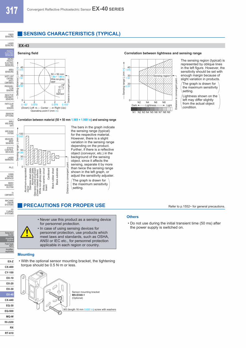
SENSING CHARACTERISTICS (TYPICAL)
EX-43
Sensing field Correlation between lightness and sensing range
The sensing region (typical) is represented by oblique lines in the left figure. However, the sensitivity should be set with enough margin because of slight variation in products.
Set
ting
dist
ance
L (m
m in
) 401.575
0
200.787
301.181
40.157
40.157
20.079
20.079
0
(Down) Left Right (Up)Operating point ℓ (mm in)
Center
Sensor
Lℓ
Dista
nce t
o con
verg
ent p
oint
50 × 50 mm1.969 × 1.969 inWhite non-glossypaper
Correlation between material (50 × 50 mm 1.969 × 1.969 in) and sensing rangeS
ensi
ng ra
nge
L (m
m in
)
Sensing region
0N2 N4 N6 N8
Dark
N1 N2 N3 N4 N5 N6 N7 N8 N9
Lightness Light
301.181
200.787
401.575
Dis
tanc
e to
con
verg
ent p
oint
The bars in the graph indicate the sensing range (typical) for the respective material. However, there is a slight variation in the sensing range depending on the product. Further, if there is a reflective object (conveyor, etc.) in the background of the sensing object, since it affects the sensing, separate it by more than twice the sensing range shown in the left graph, or adjust the sensitivity adjuster.
Sen
sing
rang
e L
(mm
in) 100
3.937
301.181
501.969
0
Dis
tanc
e to
con
verg
ent p
oint
Bla
ck s
ubst
rate
Bla
ck ru
bber
she
et
Car
dboa
rd
Whi
te c
eram
ic c
ircui
tbo
ard
Whi
te n
on-g
loss
y pa
per
Sta
inle
ss s
teel
pla
teA
lum
inum
pla
te
Alu
min
um-e
vapo
rate
dm
irror
Glas
s epo
xy pr
inted
circu
it boa
rd(G
reen
mas
ked
surfa
ce)
PRECAUTIONS FOR PROPER USE Refer to p.1552~ for general precautions.
Mounting• With the optional sensor mounting bracket, the tightening
torque should be 0.5 N·m or less.
M3 (length 16 mm 0.630 in) screw with washers
Sensor mounting bracketMS-EX40-1(Optional)
Others• Do not use during the initial transient time (50 ms) after
the power supply is switched on.
• Never use this product as a sensing device for personnel protection.
• In case of using sensing devices for personnel protection, use products which meet laws and standards, such as OSHA, ANSI or IEC etc., for personnel protection applicable in each region or country.
The graph is drawn for the maximum sensitivity setting.
Lightness shown on the left may differ slightly from the actual object condition.
The graph is drawn for the maximum sensitivity setting.
Convergent Reflective Photoelectric Sensor EX-40 SERIES 318
FIBERSENSORS
LASERSENSORS
PHOTO-ELECTRICSENSORSMICROPHOTO-ELECTRICSENSORS
AREASENSORS
SAFETY LIGHT CURTAINS /SAFETY COMPONENTSPRESSURE / FLOWSENSORS
INDUCTIVEPROXIMITYSENSORS
PARTICULARUSE SENSORS
SENSOROPTIONS
SIMPLEWIRE-SAVINGUNITS
WIRE-SAVING SYSTEMS
MEASURE-MENTSENSORS
STATIC CONTROL DEVICES
LASERMARKERS
PLC
HUMAN MACHINE INTERFACES
ENERGY MANAGEMENT SOLUTIONS
FA COMPONENTS
MACHINE VISION SYSTEMS
UV CURING SYSTEMS
Selection GuideAmplifier Built-inPower Supply Built-inAmplifier-separated
EX-Z
CX-400
CY-100
EX-10
EX-20
EX-30
EX-40
CX-440
EQ-30
EQ-500
MQ-W
RX-LS200
RX
RT-610
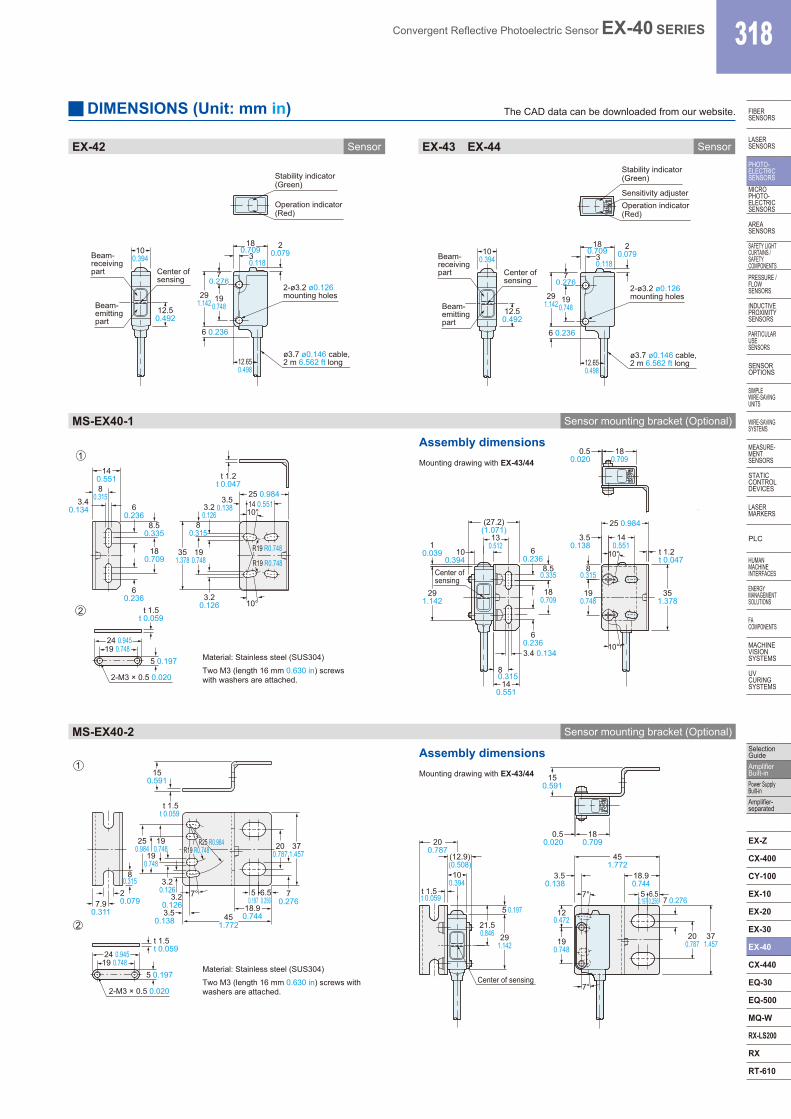
EX-42 EX-43 EX-44Sensor Sensor
DIMENSIONS (Unit: mm in) The CAD data can be downloaded from our website.
100.394
12.50.492
291.142
180.709
30.118
70.276
190.748
6 0.236
ø3.7 ø0.146 cable,2 m 6.562 ft long
20.079
2-ø3.2 ø0.126 mounting holes
Stability indicator(Green)
Operation indicator(Red)
Beam-receivingpart Center of
sensing
Beam-emittingpart
12.650.498
12.650.498
100.394
12.50.492
291.142
180.709
30.118
70.276
190.748
6 0.236
ø3.7 ø0.146 cable,2 m 6.562 ft long
20.079
2-ø3.2 ø0.126 mounting holes
Beam-receivingpart Center of
sensing
Beam-emittingpart
Stability indicator(Green)
Operation indicator(Red)
Sensitivity adjuster
MS-EX40-1 Sensor mounting bracket (Optional)
Material: Stainless steel (SUS304)Two M3 (length 16 mm 0.630 in) screws with washers are attached.
Assembly dimensions
14 0.551
3.4 0.134 3.2
0.126
35 1.378
19 0.748
3.2 0.126
8 0.315
3.5 0.138 6
0.236 8.5
0.335
18 0.709
6 0.236
t 1.5 t 0.059
t 1.2 t 0.047
10°
10°
25 0.984 14 0.551
R19 R0.748
R19 R0.748
5 0.197
2-M3 × 0.5 0.020
24 0.945 19 0.748
8 0.315
1
2
10.039
291.142
Center ofsensing
100.394
(27.2)(1.071)
130.512
140.551
3.4 0.134
8 0.315
8.50.335
0.50.020
180.709
3.50.138
140.551
10° t 1.2t 0.047
80.315
10°
60.236
60.236
180.709
25 0.984
351.378
190.748
Mounting drawing with EX-43/44
MS-EX40-2 Sensor mounting bracket (Optional)
Assembly dimensions
Material: Stainless steel (SUS304)Two M3 (length 16 mm 0.630 in) screws with washers are attached.
451.772
150.591
250.984
80.315
7° 7.9
0.311
t 1.5t 0.059
20.079
190.748
190.748
3.20.126
3.20.1263.5
0.138
t 1.5t 0.059
R25 R0.984R19 R0.748
18.90.744
50.197
6.50.256
70.276
371.457
200.787
24 0.94519 0.748
5 0.197
2-M3 × 0.5 0.020
1
2
200.787
t 1.5t 0.059
291.142
100.394
Center of sensing
5 0.197
0.50.020
180.709
451.772
3.50.138
18.90.744
50.197
6.50.256
7°7 0.276
150.591
200.787
371.457
(12.9)(0.508)
21.50.846
190.748
7°
120.472
Mounting drawing with EX-43/44