Embed Size (px)
Citation preview
CT
Thoiawccitpttwagc
RTRfmtnptoea
*
†W
A
0d
onventional Radiography of the Shoulderimothy G. Sanders, Col, USAF, MC,* and Sean L. Jersey, Lt, USAF, MSC†
vs
ATubaontcvsatahwrtepgevcfdso
GTv3bpotpjt
he shoulder girdle is a complex anatomic structure de-signed to maximize three-dimensional motion of the
and and opposing thumb, and although the shoulder isften thought of as synonymous with the glenohumeral joint,t is actually composed of four separate joints (glenohumeral,cromioclavicular, sternoclavicular, and scapulothoracic), asell as numerous muscles and ligaments that act synergisti-
ally to optimize motion of the upper extremity. Advances inross-sectional imaging over the past decade have revolution-zed imaging of the shoulder girdle, especially with regard tohe soft-tissue structures. As a result, conventional radiogra-hy is often overlooked and underutilized as a diagnosticool. This article will focus on conventional radiography ofhe glenohumeral joint and the acromioclavicular joint. Itill begin with a review of the basic radiographic techniques
nd anatomy followed by a discussion of conventional radio-raphic findings that can be seen in common disorders in-luding trauma, impingement syndrome, and arthritis.
adiographicechnique and Anatomy
adiographs are often the first imaging examination per-ormed on an individual with a suspected shoulder abnor-
ality, and the complex anatomy of the shoulder has lead tohe development of numerous radiographic views and tech-iques, each designed to optimize the evaluation of specificarts of the shoulder girdle. Knowledge of the standard viewshat are available as well as the advantages and disadvantagesf each projection will aid in optimizing the radiographicvaluation based on the clinical presentation and suspectedbnormality. Below is a description of the most common
Department of Radiology, Uniform Services University of the Health Sci-ences, Bethesda, MD.
Uniform Services University of the Health Sciences, Bethesda, MD.ork performed at Uniform Services University of the Health Sciences. The
opinions and assertions contained herein are those of the authors andshould not be construed as official or as representing the opinions of theDepartment of the Air Force or the Department of Defense.
ddress reprint requests to Timothy G. Sanders, Col, USAF, MC, Depart-ment of Radiology, Uniform Services University of the Health Sciences,4301 Jones Bridge Road, Bldg. C, Rm. 1071, Bethesda, MD 20814-4799.
dE-mail: [email protected]
037-198X/05/$-see front matter © 2005 Elsevier Inc. All rights reserved.oi:10.1053/j.ro.2005.01.012
iews of the shoulder, although numerous variations exist foreveral of the views.1
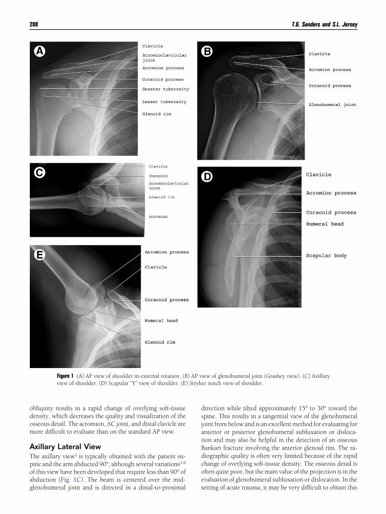
nteroposterior (AP) Shoulder Viewhe AP projection1 is usually obtained with the patient in thepright or supine position and with the coronal plane of theody parallel to the cassette (Fig. 1A). The beam is directed intrue AP direction relative to the body. This results in slightverlap of the glenoid rim and the humeral head as the gle-ohumeral joint is tilted anteriorly approximately 40°. Addi-ionally, the lateral border of the scapula and the medialortex of the proximal humerus form a gentle, smooth con-ex arch, known as scapulohumeral or Moloney’s arch. Thetandard AP view of the shoulder can be performed with therm in neutral position, internal rotation, or external rota-ion. On internal rotation, the humeral head has the appear-nce of an ice-cream cone. On external rotation, the humeralead has the appearance of an Indian axe. When comparedith other views of the shoulder, this position allows for
elatively uniform distribution of soft-tissue density acrosshe anatomy, thus providing excellent osseous detail of thentire shoulder girdle. As a result, one or more of the AProjections are almost always included in the standard radio-raphic examination of the shoulder. These views allow forxcellent visualization of the glenohumeral joint, acromiocla-icular (AC) joint, and the adjacent osseous structures in-luding the distal clavicle and scapula and thus are very help-ul in the setting of acute trauma to evaluate for fracture orislocation and can also demonstrate abnormalities in theetting of chronic shoulder pain, including calcific tendonitisr bursitis, and AC joint arthritis.
lenohumeral “True” AP (Grashey) Viewhe “true” or Grashey AP view differs from the standard APiew in that the patient is rotated posteriorly approximately5° to 45° so that the plane of the scapula rather than theody parallels the cassette (Fig. 1B). The beam is still directederpendicular to the cassette and this eliminates the overlapf the glenoid rim and the humeral head, providing a tangen-ial view of the glenohumeral joint.1 The advantage of thisrojection is that it allows for evaluation of the glenohumeral
oint space, demonstrates subtle superior or inferior migra-ion of the humeral head often seen with instability, and
etects joint space narrowing seen in arthritis. However, the207
odom
ATpoag
dsjatBdcoe
) Stryk
208 T.G. Sanders and S.L. Jersey
bliquity results in a rapid change of overlying soft-tissueensity, which decreases the quality and visualization of thesseous detail. The acromion, AC joint, and distal clavicle areore difficult to evaluate than on the standard AP view.
xillary Lateral Viewhe axillary view2 is typically obtained with the patient su-ine and the arm abducted 90°, although several variations3-8
f this view have been developed that require less than 90° ofbduction (Fig. 1C). The beam is centered over the mid-
Figure 1 (A) AP view of shoulder in external rotation. (Bview of shoulder. (D) Scapular “Y” view of shoulder. (E
lenohumeral joint and is directed in a distal-to-proximal s
irection while tilted approximately 15° to 30° toward thepine. This results in a tangential view of the glenohumeraloint from below and is an excellent method for evaluating fornterior or posterior glenohumeral subluxation or disloca-ion and may also be helpful in the detection of an osseousankart fracture involving the anterior glenoid rim. The ra-iographic quality is often very limited because of the rapidhange of overlying soft-tissue density. The osseous detail isften quite poor, but the main value of the projection is in thevaluation of glenohumeral subluxation or dislocation. In the
iew of glenohumeral joint (Grashey view). (C) Axillaryer notch view of shoulder.
) AP v
etting of acute trauma, it may be very difficult to obtain this
pthocoinpbtrpca
STpts“ccipoluavt
STtobmoetft
APTstpadstdt
ot
r
TTtifbafggrra
AAdppheultpIesotacc
Td
Conventional radiography of the shoulder 209
rojection, as the patient may be unable to adequately abducthe arm. Numerous variations of the standard axillary viewave been developed, some to minimize required abductionf the arm in the setting of acute trauma, others to emphasizeertain anatomic features. The West Point View is one examplef a variation of the lateral axillary view that was developed tomprove detection of a Bankart fracture of the anterior gle-oid rim.9 It is obtained by placing the patient in the proneosition with the arm abducted 90° from the long axis of theody with the elbow and forearm hanging off the side of theable. The beam is directed 15° to 25° in an inferior-to-supe-ior direction and tilted 25° toward the spine. Although thisrojection improves detection of an osseous Bankart lesion, itan be difficult if not impossible to obtain in the setting ofcute trauma.
capular “Y” Viewhe scapular Y view10 is obtained with the patient upright orrone with the anterior aspect of the affected side rotated 30°o 45° toward the cassette (Fig. 1D). The scapular body iseen in tangent and the glenoid fossa is seen en face as aY”-shaped intersection of the scapular body, acromion pro-ess, and coracoid process. The humeral head should beentered over the glenoid fossa. This view can be very helpfuln the setting of acute trauma to evaluate for anterior orosterior dislocation as the patient can be imaged with littler no movement of the arm and the projection obtains aateral projection of the glenohumeral joint. This view is alsoseful for delineating fractures of the coracoid process, scapula,cromion process, and proximal humeral shaft. The scapular Yiew is also used to evaluate the contour of the undersurface ofhe acromion process when “typing” the acromion.
tryker Notch Viewhe Stryker notch view11 can be obtained with the patient in
he supine or upright position. The arm is extended verticallyverhead; elbow is flexed, and the hand is supported on theack of the head (Fig. 1E). The beam is directed toward theid axilla and is tilted 10° cephalic. This view nicely dem-
nstrates the posterolateral aspect of the humeral head and isxcellent for depicting a Hill–Sachs deformity or flattening ofhe posterolateral humeral head. Evaluation of glenoid rimractures or subtle glenohumeral subluxation is limited onhis view.
cromioclavicular Articulations AP and PArojectionshe AC joints are best evaluated in the erect position (eitheritting or standing) with the back of the patient flat againsthe cassette.1 The arms should hang freely at the sides and theatient may hold sandbags of equal weight in each hand. Theddition of weights will accentuate AC joint separation byemonstrating elevation of the distal clavicle on the injuredide. The beam is directed toward the midline of the body athe level of the AC joints. This projection can be used toemonstrate AC joint pathology including fracture, separa-
ion, and arthritis. Comparison of the contralateral side can tften aid in the detection of subtle abnormalities involvinghe AC joint.
Table 1 is a checklist of the important landmarks in theadiographic evaluation of the shoulder.
raumarauma is a common indication for obtaining radiographs of
he shoulder and indeed radiography is often the first imag-ng study to be performed in the setting of shoulder painollowing trauma. The specific injury is usually dependent onoth the age of the patient as well as the mechanism of injury,nd the most common injuries include AC joint separation,racture of the clavicle, scapula, or proximal humerus, andlenohumeral dislocation. Selection of the proper radio-raphic views as well as a working knowledge of the normaladiographic anatomy and an understanding of the commonadiographic signs of injury will ensure the most accuratessessment with conventional radiographs.
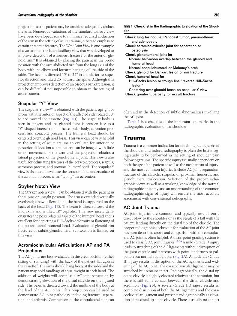
C Joint TraumaC joint injuries are common and typically result from airect blow to the shoulder or as the result of a fall with theatient landing directly on the distal tip of the clavicle. Theroper radiographic technique for evaluation of the AC jointas been described above and comparison with the contralat-ral AC joint is often helpful. A three-point grading system issed to classify AC joint injuries.12-14 A mild (Grade I) injury
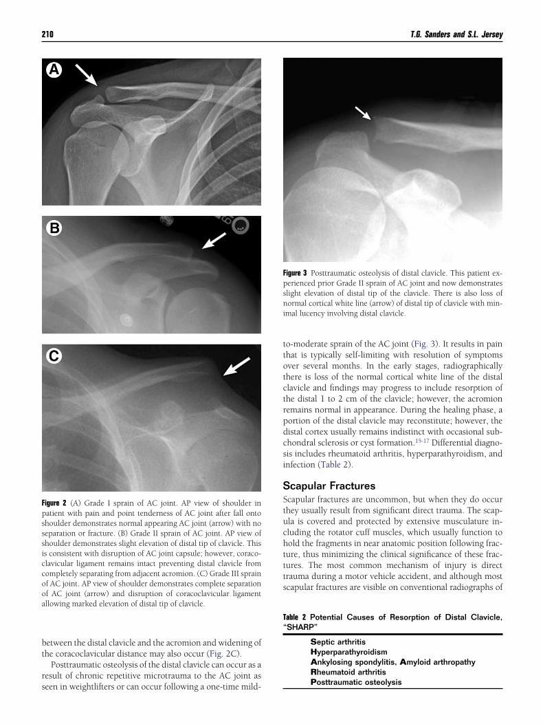
eads to stretching of the AC ligaments without disruption ofhe joint capsule and presents with point tenderness to pal-ation but normal radiographs (Fig. 2A). A moderate (GradeI) injury results in disruption of the AC ligaments and wid-ning of the AC joint. The coracoclavicular ligament may betretched but remains intact. Radiographically, the distal tipf the clavicle is slightly elevated relative to the acromion, buthere is still some contact between the distal clavicle andcromion (Fig. 2B). A severe (Grade III) injury results inomplete disruption of both the AC ligaments and the cora-oclavicular ligament and presents radiographically as eleva-
able 1 Checklist in the Radiographic Evaluation of the Shoul-er
Check lung for nodule, Pancoast tumor, pneumothoraxand adenopathy
Check acromioclavicular joint for separation orosteolysis
Check glenohumeral joint forNormal half-moon overlap between the glenoid and
humeral headNormal scapulohumeral or Moloney’s arch
Check glenoid for Bankart lesion or rim fractureCheck humeral head for
Hill–Sachs lesion or trough line “reverse Hill–Sachslesion”
Centering over glenoid fossa on scapular Y-viewCheck greater tuberosity for occult fracture
ion of the distal tip of the clavicle. There is usually no contact
bt
rs
ttotctrpdcsi
SStuchttts
Fpsssiccooa
Fpsni
T“
210 T.G. Sanders and S.L. Jersey
etween the distal clavicle and the acromion and widening ofhe coracoclavicular distance may also occur (Fig. 2C).
Posttraumatic osteolysis of the distal clavicle can occur as aesult of chronic repetitive microtrauma to the AC joint as
igure 2 (A) Grade I sprain of AC joint. AP view of shoulder inatient with pain and point tenderness of AC joint after fall ontohoulder demonstrates normal appearing AC joint (arrow) with noeparation or fracture. (B) Grade II sprain of AC joint. AP view ofhoulder demonstrates slight elevation of distal tip of clavicle. Thiss consistent with disruption of AC joint capsule; however, coraco-lavicular ligament remains intact preventing distal clavicle fromompletely separating from adjacent acromion. (C) Grade III sprainf AC joint. AP view of shoulder demonstrates complete separationf AC joint (arrow) and disruption of coracoclavicular ligamentllowing marked elevation of distal tip of clavicle.
een in weightlifters or can occur following a one-time mild-
o-moderate sprain of the AC joint (Fig. 3). It results in painhat is typically self-limiting with resolution of symptomsver several months. In the early stages, radiographicallyhere is loss of the normal cortical white line of the distallavicle and findings may progress to include resorption ofhe distal 1 to 2 cm of the clavicle; however, the acromionemains normal in appearance. During the healing phase, aortion of the distal clavicle may reconstitute; however, theistal cortex usually remains indistinct with occasional sub-hondral sclerosis or cyst formation.15-17 Differential diagno-is includes rheumatoid arthritis, hyperparathyroidism, andnfection (Table 2).
capular Fracturescapular fractures are uncommon, but when they do occurhey usually result from significant direct trauma. The scap-la is covered and protected by extensive musculature in-luding the rotator cuff muscles, which usually function toold the fragments in near anatomic position following frac-ure, thus minimizing the clinical significance of these frac-ures. The most common mechanism of injury is directrauma during a motor vehicle accident, and although mostcapular fractures are visible on conventional radiographs of
igure 3 Posttraumatic osteolysis of distal clavicle. This patient ex-erienced prior Grade II sprain of AC joint and now demonstrateslight elevation of distal tip of the clavicle. There is also loss oformal cortical white line (arrow) of distal tip of clavicle with min-
mal lucency involving distal clavicle.
able 2 Potential Causes of Resorption of Distal Clavicle,SHARP”
Septic arthritisHyperparathyroidismAnkylosing spondylitis, Amyloid arthropathyRheumatoid arthritis
Posttraumatic osteolysis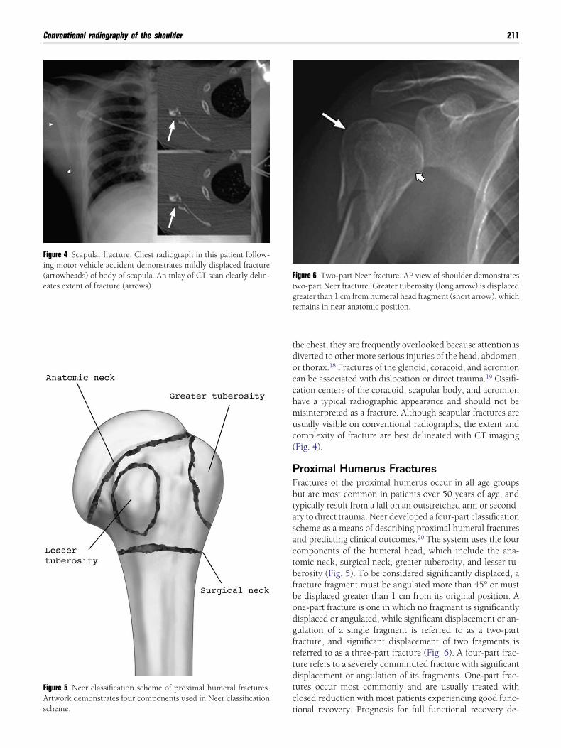
tdocchmuc(
PFbtasactbfbodgfrtdtct
Fi(eates extent of fracture (arrows).
FAscheme.
Ftgr
Conventional radiography of the shoulder 211
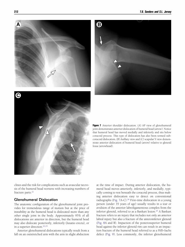
he chest, they are frequently overlooked because attention isiverted to other more serious injuries of the head, abdomen,r thorax.18 Fractures of the glenoid, coracoid, and acromionan be associated with dislocation or direct trauma.19 Ossifi-ation centers of the coracoid, scapular body, and acromionave a typical radiographic appearance and should not beisinterpreted as a fracture. Although scapular fractures aresually visible on conventional radiographs, the extent andomplexity of fracture are best delineated with CT imagingFig. 4).
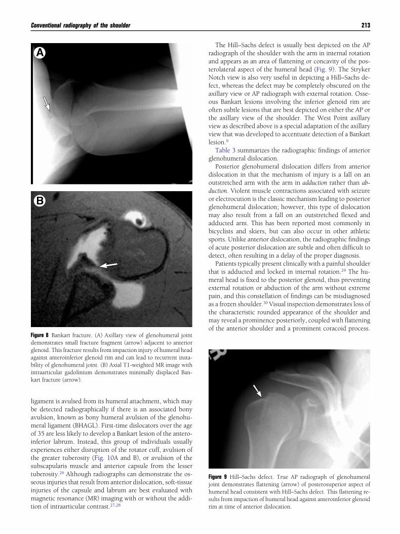
roximal Humerus Fracturesractures of the proximal humerus occur in all age groupsut are most common in patients over 50 years of age, andypically result from a fall on an outstretched arm or second-ry to direct trauma. Neer developed a four-part classificationcheme as a means of describing proximal humeral fracturesnd predicting clinical outcomes.20 The system uses the fouromponents of the humeral head, which include the ana-omic neck, surgical neck, greater tuberosity, and lesser tu-erosity (Fig. 5). To be considered significantly displaced, aracture fragment must be angulated more than 45° or muste displaced greater than 1 cm from its original position. Ane-part fracture is one in which no fragment is significantlyisplaced or angulated, while significant displacement or an-ulation of a single fragment is referred to as a two-partracture, and significant displacement of two fragments iseferred to as a three-part fracture (Fig. 6). A four-part frac-ure refers to a severely comminuted fracture with significantisplacement or angulation of its fragments. One-part frac-ures occur most commonly and are usually treated withlosed reduction with most patients experiencing good func-
igure 6 Two-part Neer fracture. AP view of shoulder demonstrateswo-part Neer fracture. Greater tuberosity (long arrow) is displacedreater than 1 cm from humeral head fragment (short arrow), whichemains in near anatomic position.
igure 4 Scapular fracture. Chest radiograph in this patient follow-ng motor vehicle accident demonstrates mildly displaced fracturearrowheads) of body of scapula. An inlay of CT scan clearly delin-
igure 5 Neer classification scheme of proximal humeral fractures.rtwork demonstrates four components used in Neer classification
ional recovery. Prognosis for full functional recovery de-
csf
GTviodmi
f
amcirpaifl(ht
212 T.G. Sanders and S.L. Jersey
lines and the risk for complications such as avascular necro-is of the humeral head worsens with increasing numbers ofracture parts.21
lenohumeral Dislocationhe anatomic configuration of the glenohumeral joint pro-ides for tremendous range of motion but at the price ofnstability as the humeral head is dislocated more than anyther single joint in the body. Approximately 95% of allislocations are anterior in direction, but the humeral headay also dislocate posteriorly, inferiorly (luxatio erecta), or
n a superior direction.22,23
Anterior glenohumeral dislocations typically result from a
all on an outstretched arm with the arm in slight abduction dt the time of impact. During anterior dislocation, the hu-eral head moves anteriorly, inferiorly, and medially, typi-
ally coming to rest beneath the coracoid process, thus mak-ng anterior dislocation easy to detect on conventionaladiographs (Fig. 7A-C).24 First-time dislocation in a youngerson (under 35 years of age) usually results in a tear orvulsion of the anterior labroligamentous complex from thenferior glenoid, referred to as a Bankart lesion.25 A Bankartracture refers to an injury that includes not only an anteriorabral injury but also a fracture of the anteroinferior glenoidFig. 8A and B). Impaction of the posterosuperior humeralead against the inferior glenoid rim can result in an impac-ion fracture of the humeral head referred to as a Hill–Sachs
re 7 Anterior shoulder dislocation. (A) AP view of glenohumeralt demonstrates anterior dislocation of humeral head (arrow). Noticehumeral head has moved medially and inferiorly and sits belowcoid process. This type of dislocation has also been termed sub-coid dislocation. (B) Axillary view and (C) scapular Y view demon-
te anterior dislocation of humeral head (arrow) relative to glenoida (arrowhead).
Figujointhatcoracorastrafoss
efect (Fig. 9). Less commonly, the inferior glenohumeral
lbamoietstsimt
ratNfaootvvl
g
dodogmabsod
tmepatmo
Fdgabik
Fjhs
Conventional radiography of the shoulder 213
igament is avulsed from its humeral attachment, which maye detected radiographically if there is an associated bonyvulsion, known as bony humeral avulsion of the glenohu-eral ligament (BHAGL). First-time dislocators over the age
f 35 are less likely to develop a Bankart lesion of the antero-nferior labrum. Instead, this group of individuals usuallyxperiences either disruption of the rotator cuff, avulsion ofhe greater tuberosity (Fig. 10A and B), or avulsion of theubscapularis muscle and anterior capsule from the lesseruberosity.26 Although radiographs can demonstrate the os-eous injuries that result from anterior dislocation, soft-tissuenjuries of the capsule and labrum are best evaluated with
agnetic resonance (MR) imaging with or without the addi-
igure 8 Bankart fracture. (A) Axillary view of glenohumeral jointemonstrates small fracture fragment (arrow) adjacent to anteriorlenoid. This fracture results from impaction injury of humeral headgainst anteroinferior glenoid rim and can lead to recurrent insta-ility of glenohumeral joint. (B) Axial T1-weighted MR image with
ntraarticular gadolinium demonstrates minimally displaced Ban-art fracture (arrow).
ion of intraarticular contrast.27,28 r
The Hill–Sachs defect is usually best depicted on the APadiograph of the shoulder with the arm in internal rotationnd appears as an area of flattening or concavity of the pos-erolateral aspect of the humeral head (Fig. 9). The Strykerotch view is also very useful in depicting a Hill–Sachs de-
ect, whereas the defect may be completely obscured on thexillary view or AP radiograph with external rotation. Osse-us Bankart lesions involving the inferior glenoid rim areften subtle lesions that are best depicted on either the AP orhe axillary view of the shoulder. The West Point axillaryiew as described above is a special adaptation of the axillaryiew that was developed to accentuate detection of a Bankartesion.9
Table 3 summarizes the radiographic findings of anteriorlenohumeral dislocation.
Posterior glenohumeral dislocation differs from anteriorislocation in that the mechanism of injury is a fall on anutstretched arm with the arm in adduction rather than ab-uction. Violent muscle contractions associated with seizurer electrocution is the classic mechanism leading to posteriorlenohumeral dislocation; however, this type of dislocationay also result from a fall on an outstretched flexed and
dducted arm. This has been reported most commonly inicyclists and skiers, but can also occur in other athleticports. Unlike anterior dislocation, the radiographic findingsf acute posterior dislocation are subtle and often difficult toetect, often resulting in a delay of the proper diagnosis.Patients typically present clinically with a painful shoulder
hat is adducted and locked in internal rotation.29 The hu-eral head is fixed to the posterior glenoid, thus preventing
xternal rotation or abduction of the arm without extremeain, and this constellation of findings can be misdiagnoseds a frozen shoulder.30 Visual inspection demonstrates loss ofhe characteristic rounded appearance of the shoulder anday reveal a prominence posteriorly, coupled with flattening
f the anterior shoulder and a prominent coracoid process.
igure 9 Hill–Sachs defect. True AP radiograph of glenohumeraloint demonstrates flattening (arrow) of posterosuperior aspect ofumeral head consistent with Hill–Sachs defect. This flattening re-ults from impaction of humeral head against anteroinferior glenoid
im at time of anterior dislocation.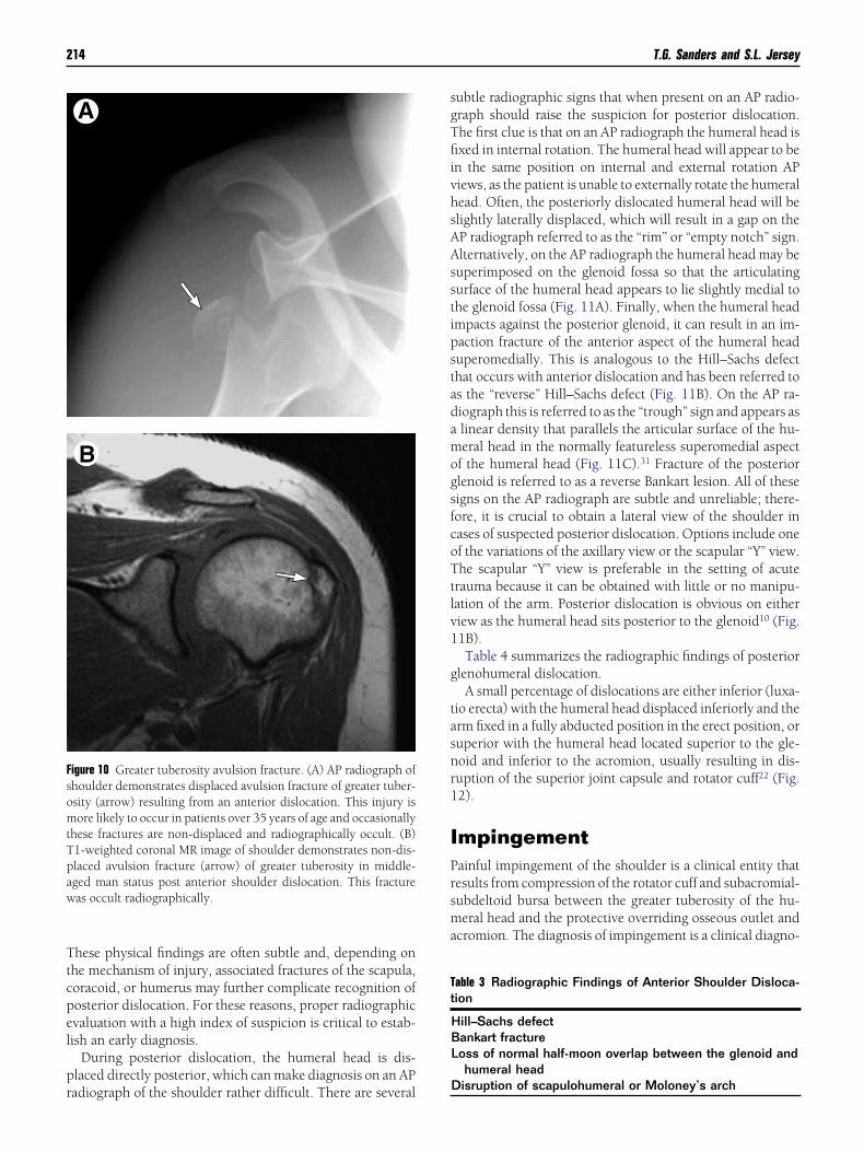
Ttcpel
pr
sgTfiivhsAAsstipstadamogsfcoTtlv1
g
tasnr1
IPrsma
FsomtTpaw
Tt
214 T.G. Sanders and S.L. Jersey
hese physical findings are often subtle and, depending onhe mechanism of injury, associated fractures of the scapula,oracoid, or humerus may further complicate recognition ofosterior dislocation. For these reasons, proper radiographicvaluation with a high index of suspicion is critical to estab-ish an early diagnosis.
During posterior dislocation, the humeral head is dis-laced directly posterior, which can make diagnosis on an AP
igure 10 Greater tuberosity avulsion fracture. (A) AP radiograph ofhoulder demonstrates displaced avulsion fracture of greater tuber-sity (arrow) resulting from an anterior dislocation. This injury isore likely to occur in patients over 35 years of age and occasionally
hese fractures are non-displaced and radiographically occult. (B)1-weighted coronal MR image of shoulder demonstrates non-dis-laced avulsion fracture (arrow) of greater tuberosity in middle-ged man status post anterior shoulder dislocation. This fractureas occult radiographically.
adiograph of the shoulder rather difficult. There are several
ubtle radiographic signs that when present on an AP radio-raph should raise the suspicion for posterior dislocation.he first clue is that on an AP radiograph the humeral head isxed in internal rotation. The humeral head will appear to be
n the same position on internal and external rotation APiews, as the patient is unable to externally rotate the humeralead. Often, the posteriorly dislocated humeral head will belightly laterally displaced, which will result in a gap on theP radiograph referred to as the “rim” or “empty notch” sign.lternatively, on the AP radiograph the humeral head may beuperimposed on the glenoid fossa so that the articulatingurface of the humeral head appears to lie slightly medial tohe glenoid fossa (Fig. 11A). Finally, when the humeral headmpacts against the posterior glenoid, it can result in an im-action fracture of the anterior aspect of the humeral headuperomedially. This is analogous to the Hill–Sachs defecthat occurs with anterior dislocation and has been referred tos the “reverse” Hill–Sachs defect (Fig. 11B). On the AP ra-iograph this is referred to as the “trough” sign and appears aslinear density that parallels the articular surface of the hu-eral head in the normally featureless superomedial aspect
f the humeral head (Fig. 11C).31 Fracture of the posteriorlenoid is referred to as a reverse Bankart lesion. All of theseigns on the AP radiograph are subtle and unreliable; there-ore, it is crucial to obtain a lateral view of the shoulder inases of suspected posterior dislocation. Options include onef the variations of the axillary view or the scapular “Y” view.he scapular “Y” view is preferable in the setting of acute
rauma because it can be obtained with little or no manipu-ation of the arm. Posterior dislocation is obvious on eitheriew as the humeral head sits posterior to the glenoid10 (Fig.1B).Table 4 summarizes the radiographic findings of posterior
lenohumeral dislocation.A small percentage of dislocations are either inferior (luxa-
io erecta) with the humeral head displaced inferiorly and therm fixed in a fully abducted position in the erect position, oruperior with the humeral head located superior to the gle-oid and inferior to the acromion, usually resulting in dis-uption of the superior joint capsule and rotator cuff22 (Fig.2).
mpingementainful impingement of the shoulder is a clinical entity thatesults from compression of the rotator cuff and subacromial-ubdeltoid bursa between the greater tuberosity of the hu-eral head and the protective overriding osseous outlet and
cromion. The diagnosis of impingement is a clinical diagno-
able 3 Radiographic Findings of Anterior Shoulder Disloca-ion
Hill–Sachs defectBankart fractureLoss of normal half-moon overlap between the glenoid and
humeral head
Disruption of scapulohumeral or Moloney’s arch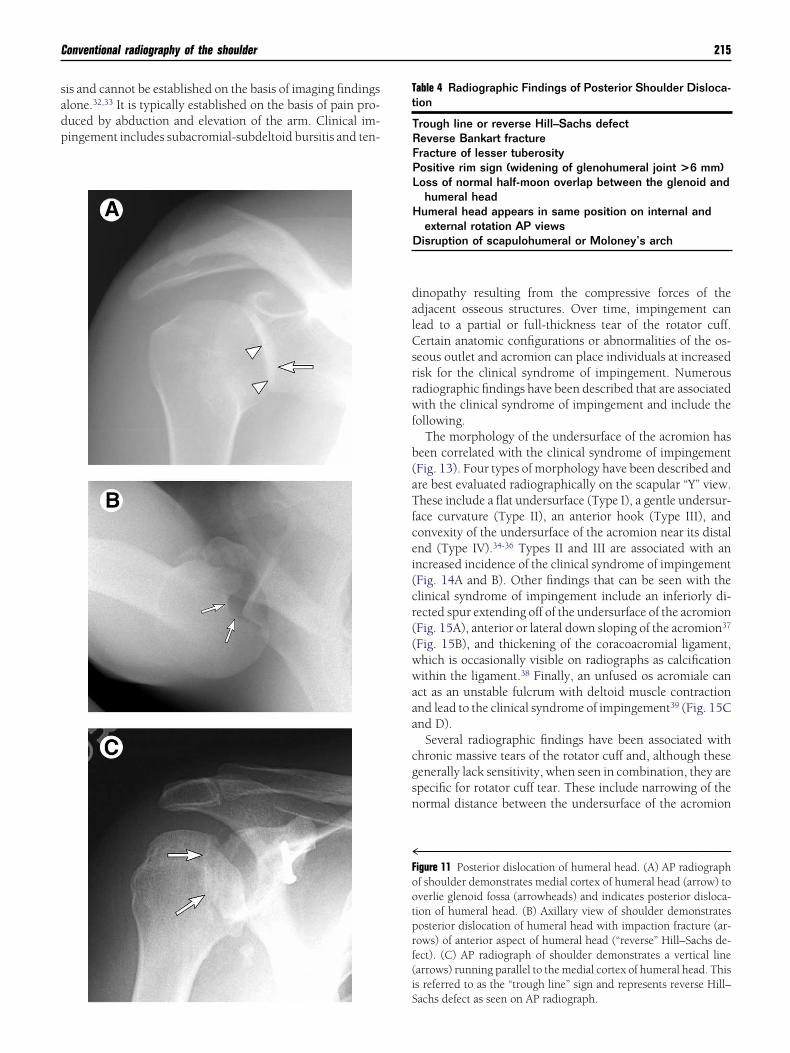
sadp
dalCsrrwf
b(aTfcei(cr((wwaaa
cgsn
4Footprf(i
Tt
Conventional radiography of the shoulder 215
is and cannot be established on the basis of imaging findingslone.32,33 It is typically established on the basis of pain pro-uced by abduction and elevation of the arm. Clinical im-ingement includes subacromial-subdeltoid bursitis and ten-
S
inopathy resulting from the compressive forces of thedjacent osseous structures. Over time, impingement canead to a partial or full-thickness tear of the rotator cuff.ertain anatomic configurations or abnormalities of the os-
eous outlet and acromion can place individuals at increasedisk for the clinical syndrome of impingement. Numerousadiographic findings have been described that are associatedith the clinical syndrome of impingement and include the
ollowing.The morphology of the undersurface of the acromion has
een correlated with the clinical syndrome of impingementFig. 13). Four types of morphology have been described andre best evaluated radiographically on the scapular “Y” view.hese include a flat undersurface (Type I), a gentle undersur-
ace curvature (Type II), an anterior hook (Type III), andonvexity of the undersurface of the acromion near its distalnd (Type IV).34-36 Types II and III are associated with anncreased incidence of the clinical syndrome of impingementFig. 14A and B). Other findings that can be seen with thelinical syndrome of impingement include an inferiorly di-ected spur extending off of the undersurface of the acromionFig. 15A), anterior or lateral down sloping of the acromion37
Fig. 15B), and thickening of the coracoacromial ligament,hich is occasionally visible on radiographs as calcificationithin the ligament.38 Finally, an unfused os acromiale can
ct as an unstable fulcrum with deltoid muscle contractionnd lead to the clinical syndrome of impingement39 (Fig. 15Cnd D).
Several radiographic findings have been associated withhronic massive tears of the rotator cuff and, although theseenerally lack sensitivity, when seen in combination, they arepecific for rotator cuff tear. These include narrowing of theormal distance between the undersurface of the acromion
™™™™™™™™™™™™™™™™™™™™™™™™™™™™™™™™™™™igure 11 Posterior dislocation of humeral head. (A) AP radiographf shoulder demonstrates medial cortex of humeral head (arrow) toverlie glenoid fossa (arrowheads) and indicates posterior disloca-ion of humeral head. (B) Axillary view of shoulder demonstratesosterior dislocation of humeral head with impaction fracture (ar-ows) of anterior aspect of humeral head (“reverse” Hill–Sachs de-ect). (C) AP radiograph of shoulder demonstrates a vertical linearrows) running parallel to the medial cortex of humeral head. Thiss referred to as the “trough line” sign and represents reverse Hill–
able 4 Radiographic Findings of Posterior Shoulder Disloca-ion
Trough line or reverse Hill–Sachs defectReverse Bankart fractureFracture of lesser tuberosityPositive rim sign (widening of glenohumeral joint >6 mm)Loss of normal half-moon overlap between the glenoid and
humeral headHumeral head appears in same position on internal and
external rotation AP viewsDisruption of scapulohumeral or Moloney’s arch
achs defect as seen on AP radiograph.
a7mofittccs
r
AAt
rpdt
RSiGiecpt
F
Fuac
Fhg
216 T.G. Sanders and S.L. Jersey
nd the superior margin of the humeral head40 (less than 6 tomm is generally considered abnormal), reversal of the nor-al convexity of the undersurface of the acromion, formation
f subcortical cysts on the undersurface of the acromion, andnally, cystic change in the region of the greater tuberosity ofhe humeral head. Radiographic findings of superior migra-ion of the humeral head combined with subcortical cystichange of the greater tuberosity allows for the diagnosis ofhronic massive rotator cuff tear with the greatest degree ofpecificity (Fig. 16).41,42
Table 5 summarizes the radiographic findings of chronicotator cuff tear.
rthritisrthritis is a common clinical entity that often involves either
he glenohumeral joint or the AC joint. Conventional radiog-
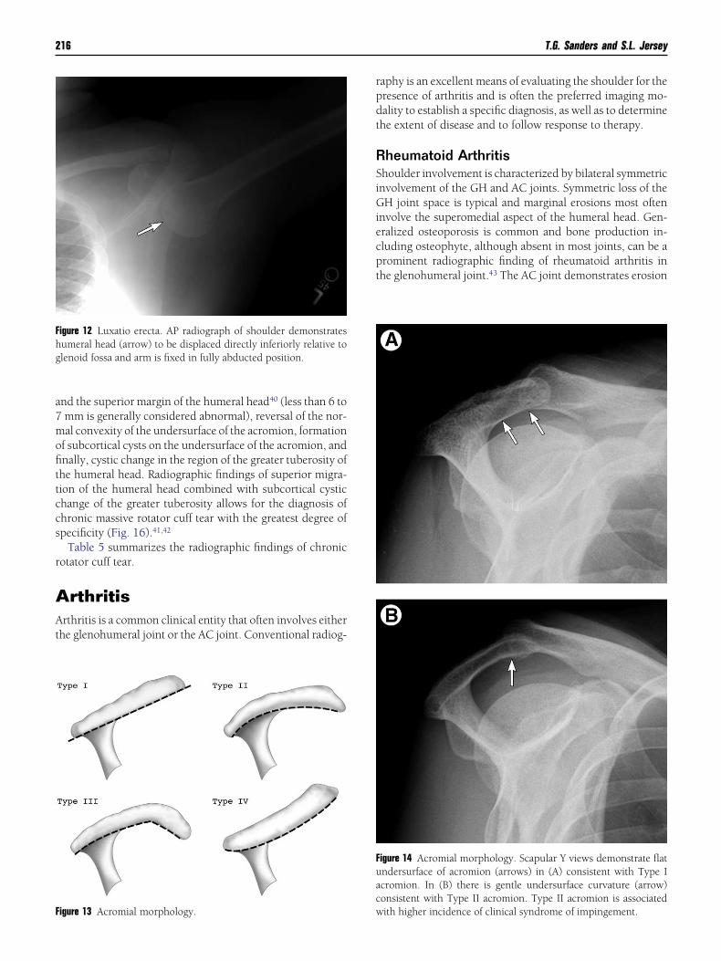
igure 12 Luxatio erecta. AP radiograph of shoulder demonstratesumeral head (arrow) to be displaced directly inferiorly relative tolenoid fossa and arm is fixed in fully abducted position.
igure 13 Acromial morphology. w
aphy is an excellent means of evaluating the shoulder for theresence of arthritis and is often the preferred imaging mo-ality to establish a specific diagnosis, as well as to determinehe extent of disease and to follow response to therapy.
heumatoid Arthritishoulder involvement is characterized by bilateral symmetricnvolvement of the GH and AC joints. Symmetric loss of theH joint space is typical and marginal erosions most often
nvolve the superomedial aspect of the humeral head. Gen-ralized osteoporosis is common and bone production in-luding osteophyte, although absent in most joints, can be arominent radiographic finding of rheumatoid arthritis inhe glenohumeral joint.43 The AC joint demonstrates erosion
igure 14 Acromial morphology. Scapular Y views demonstrate flatndersurface of acromion (arrows) in (A) consistent with Type Icromion. In (B) there is gentle undersurface curvature (arrow)onsistent with Type II acromion. Type II acromion is associated
ith higher incidence of clinical syndrome of impingement.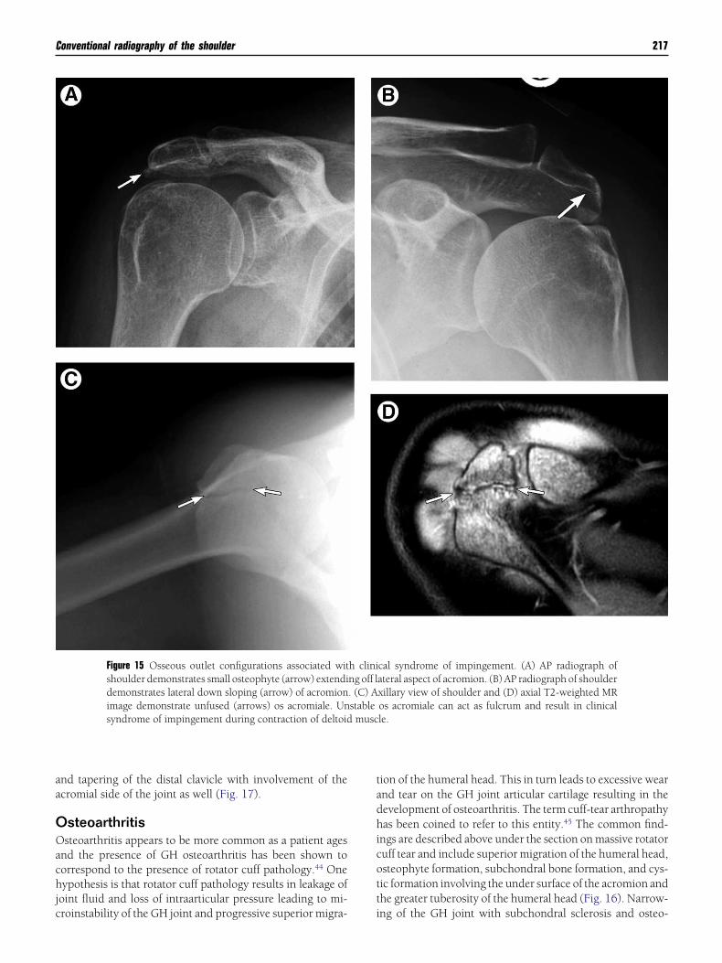
aa
OOachjc
tadhicott
Conventional radiography of the shoulder 217
nd tapering of the distal clavicle with involvement of thecromial side of the joint as well (Fig. 17).
steoarthritissteoarthritis appears to be more common as a patient ages
nd the presence of GH osteoarthritis has been shown toorrespond to the presence of rotator cuff pathology.44 Oneypothesis is that rotator cuff pathology results in leakage of
oint fluid and loss of intraarticular pressure leading to mi-
Figure 15 Osseous outlet configurations associated witshoulder demonstrates small osteophyte (arrow) extendidemonstrates lateral down sloping (arrow) of acromionimage demonstrate unfused (arrows) os acromiale. Unsyndrome of impingement during contraction of deltoid
roinstability of the GH joint and progressive superior migra- i
ion of the humeral head. This in turn leads to excessive wearnd tear on the GH joint articular cartilage resulting in theevelopment of osteoarthritis. The term cuff-tear arthropathyas been coined to refer to this entity.45 The common find-
ngs are described above under the section on massive rotatoruff tear and include superior migration of the humeral head,steophyte formation, subchondral bone formation, and cys-ic formation involving the under surface of the acromion andhe greater tuberosity of the humeral head (Fig. 16). Narrow-
cal syndrome of impingement. (A) AP radiograph ofateral aspect of acromion. (B) AP radiograph of shoulderxillary view of shoulder and (D) axial T2-weighted MRos acromiale can act as fulcrum and result in clinicalle.
h clining off l. (C) Astablemusc
ng of the GH joint with subchondral sclerosis and osteo-
pmi
CDTjtschGtsm
HAdp
FsmpaD
Ftw(sr
T
Fg
218 T.G. Sanders and S.L. Jersey
hyte formation is also common.46 These changes also com-only involve the AC joint following trauma and typically
nvolve both sides of the joint.
alcium Pyrophosphate Crystal Depositionisease
his crystalline deposition disease can involve either the ACoint or the GH joint and is one of the predisposing factorshat can lead to the development of osteoarthritis of thehoulder.47,48 Early in the disease the presence of chondro-alcinosis can be observed in either the fibrocartilage or theyaline cartilage of the joint (Fig. 18). Late in the disease theH joint will demonstrate the typical appearance of osteoar-
hritis, including joint space narrowing, subchondral sclero-is, and osteophyte formation, and the crystalline depositionay not be obvious radiographically.49
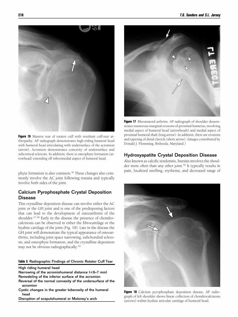
igure 16 Massive tear of rotator cuff with resultant cuff-tear ar-hropathy. AP radiograph demonstrates high-riding humeral headith humeral head articulating with undersurface of the acromion
arrow). Acromion demonstrates concavity of undersurface andubcortical sclerosis. In addition, there is osteophyte formation (ar-owhead) extending off inferomedial aspect of humeral head.
able 5 Radiographic Findings of Chronic Rotator Cuff Tear
High riding humeral headNarrowing of the acromiohumeral distance (<6–7 mm)Remodeling of the inferior surface of the acromionReversal of the normal convexity of the undersurface of the
acromionCystic changes in the greater tuberosity of the humeral
head
Disruption of scapulohumeral or Moloney’s arch(
ydroxyapatite Crystal Deposition Diseaselso known as calcific tendonitis, bursitis involves the shoul-er more often than any other joint.50 It typically results inain, localized swelling, erythema, and decreased range of
igure 17 Rheumatoid arthritis. AP radiograph of shoulder demon-trates numerous marginal erosions of proximal humerus, involvingedial aspect of humeral head (arrowheads) and medial aspect ofroximal humeral shaft (long arrow). In addition, there are erosionsnd tapering of distal clavicle (short arrow). (Images contributed byonald J. Flemming, Bethesda, Maryland.)
igure 18 Calcium pyrophosphate deposition disease. AP radio-raph of left shoulder shows linear collection of chondrocalcinosis
arrows) within hyaline articular cartilage of humeral head.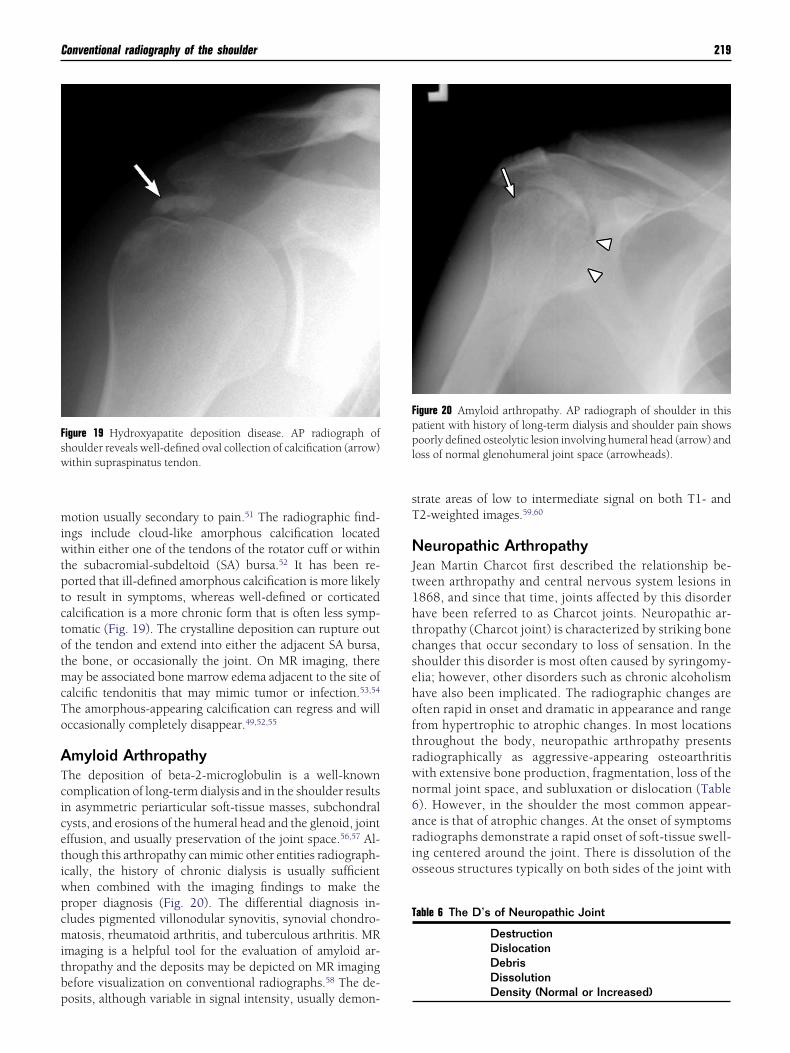
miwtptctotmcTo
ATcicetiwpcmitbp
sT
NJt1htcsehoftrwn6ario
Fsw
Fppl
T
Conventional radiography of the shoulder 219
otion usually secondary to pain.51 The radiographic find-ngs include cloud-like amorphous calcification locatedithin either one of the tendons of the rotator cuff or within
he subacromial-subdeltoid (SA) bursa.52 It has been re-orted that ill-defined amorphous calcification is more likelyo result in symptoms, whereas well-defined or corticatedalcification is a more chronic form that is often less symp-omatic (Fig. 19). The crystalline deposition can rupture outf the tendon and extend into either the adjacent SA bursa,he bone, or occasionally the joint. On MR imaging, thereay be associated bone marrow edema adjacent to the site of
alcific tendonitis that may mimic tumor or infection.53,54
he amorphous-appearing calcification can regress and willccasionally completely disappear.49,52,55
myloid Arthropathyhe deposition of beta-2-microglobulin is a well-knownomplication of long-term dialysis and in the shoulder resultsn asymmetric periarticular soft-tissue masses, subchondralysts, and erosions of the humeral head and the glenoid, jointffusion, and usually preservation of the joint space.56,57 Al-hough this arthropathy can mimic other entities radiograph-cally, the history of chronic dialysis is usually sufficienthen combined with the imaging findings to make theroper diagnosis (Fig. 20). The differential diagnosis in-ludes pigmented villonodular synovitis, synovial chondro-atosis, rheumatoid arthritis, and tuberculous arthritis. MR
maging is a helpful tool for the evaluation of amyloid ar-hropathy and the deposits may be depicted on MR imagingefore visualization on conventional radiographs.58 The de-
igure 19 Hydroxyapatite deposition disease. AP radiograph ofhoulder reveals well-defined oval collection of calcification (arrow)ithin supraspinatus tendon.
osits, although variable in signal intensity, usually demon-
trate areas of low to intermediate signal on both T1- and2-weighted images.59,60
europathic Arthropathyean Martin Charcot first described the relationship be-ween arthropathy and central nervous system lesions in868, and since that time, joints affected by this disorderave been referred to as Charcot joints. Neuropathic ar-hropathy (Charcot joint) is characterized by striking bonehanges that occur secondary to loss of sensation. In thehoulder this disorder is most often caused by syringomy-lia; however, other disorders such as chronic alcoholismave also been implicated. The radiographic changes areften rapid in onset and dramatic in appearance and rangerom hypertrophic to atrophic changes. In most locationshroughout the body, neuropathic arthropathy presentsadiographically as aggressive-appearing osteoarthritisith extensive bone production, fragmentation, loss of theormal joint space, and subluxation or dislocation (Table). However, in the shoulder the most common appear-nce is that of atrophic changes. At the onset of symptomsadiographs demonstrate a rapid onset of soft-tissue swell-ng centered around the joint. There is dissolution of thesseous structures typically on both sides of the joint with
igure 20 Amyloid arthropathy. AP radiograph of shoulder in thisatient with history of long-term dialysis and shoulder pain showsoorly defined osteolytic lesion involving humeral head (arrow) and
oss of normal glenohumeral joint space (arrowheads).
able 6 The D’s of Neuropathic Joint
DestructionDislocationDebrisDissolution
Density (Normal or Increased)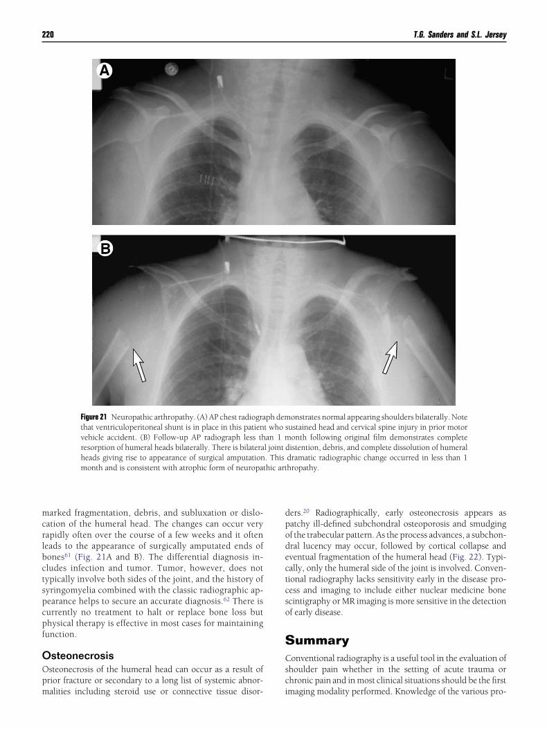
mcrlbctspcpf
OOpm
dpodectcso
SCsc
220 T.G. Sanders and S.L. Jersey
arked fragmentation, debris, and subluxation or dislo-ation of the humeral head. The changes can occur veryapidly often over the course of a few weeks and it ofteneads to the appearance of surgically amputated ends ofones61 (Fig. 21A and B). The differential diagnosis in-ludes infection and tumor. Tumor, however, does notypically involve both sides of the joint, and the history ofyringomyelia combined with the classic radiographic ap-earance helps to secure an accurate diagnosis.62 There isurrently no treatment to halt or replace bone loss buthysical therapy is effective in most cases for maintainingunction.
steonecrosissteonecrosis of the humeral head can occur as a result ofrior fracture or secondary to a long list of systemic abnor-
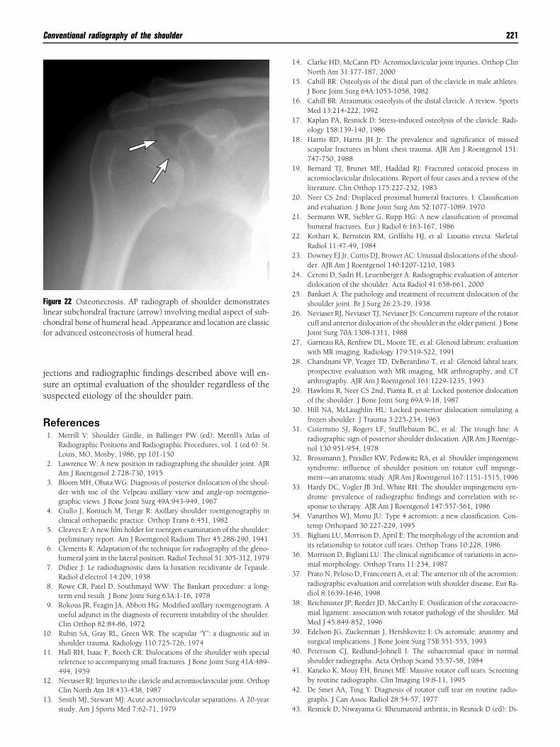
Figure 21 Neuropathic arthropathy. (A) AP chest radiograthat ventriculoperitoneal shunt is in place in this patienvehicle accident. (B) Follow-up AP radiograph less thresorption of humeral heads bilaterally. There is bilateraheads giving rise to appearance of surgical amputationmonth and is consistent with atrophic form of neuropat
alities including steroid use or connective tissue disor- i
ers.20 Radiographically, early osteonecrosis appears asatchy ill-defined subchondral osteoporosis and smudgingf the trabecular pattern. As the process advances, a subchon-ral lucency may occur, followed by cortical collapse andventual fragmentation of the humeral head (Fig. 22). Typi-ally, only the humeral side of the joint is involved. Conven-ional radiography lacks sensitivity early in the disease pro-ess and imaging to include either nuclear medicine bonecintigraphy or MR imaging is more sensitive in the detectionf early disease.
ummaryonventional radiography is a useful tool in the evaluation of
houlder pain whether in the setting of acute trauma orhronic pain and in most clinical situations should be the first
onstrates normal appearing shoulders bilaterally. Noteustained head and cervical spine injury in prior motoronth following original film demonstrates completeistention, debris, and complete dissolution of humeral
dramatic radiographic change occurred in less than 1hropathy.
ph demt who san 1 ml joint d. Thishic art
maging modality performed. Knowledge of the various pro-
jss
R
1
1
1
1
1
1
1
1
1
1
2
2
2
2
2
2
2
2
2
2
3
3
3
3
3
3
3
3
3
3
4
4
4
Flcf
Conventional radiography of the shoulder 221
ections and radiographic findings described above will en-ure an optimal evaluation of the shoulder regardless of theuspected etiology of the shoulder pain.
eferences1. Merrill V: Shoulder Girdle, in Ballinger PW (ed): Merrill’s Atlas of
Radiographic Positions and Radiographic Procedures, vol. 1 (ed 6). St.Louis, MO, Mosby, 1986, pp 101-150
2. Lawrence W: A new position in radiographing the shoulder joint. AJRAm J Roentgenol 2:728-730, 1915
3. Bloom MH, Obata WG: Diagnosis of posterior dislocation of the shoul-der with use of the Velpeau axillary view and angle-up roentgeno-graphic views. J Bone Joint Surg 49A:943-949, 1967
4. Ciullo J, Koniuch M, Tietge R: Axillary shoulder roentgenography inclinical orthopaedic practice. Orthop Trans 6:451, 1982
5. Cleaves E: A new film holder for roentgen examination of the shoulder:preliminary report. Am J Roentgenol Radium Ther 45:288-290, 1941
6. Clements R: Adaptation of the technique for radiography of the gleno-humeral joint in the lateral position. Radiol Technol 51:305-312, 1979
7. Didiee J: Le radiodiagnostic dans la luxation recidivante de l’epaule.Radiol d’electrol 14:209, 1938
8. Rowe CR, Patel D, Southmayd WW: The Bankart procedure: a long-term end result. J Bone Joint Surg 63A:1-16, 1978
9. Rokous JR, Feagin JA, Abbott HG: Modified axillary roentgenogram. Auseful adjunct in the diagnosis of recurrent instability of the shoulder.Clin Orthop 82:84-86, 1972
0. Rubin SA, Gray RL, Green WR: The scapular “Y”: a diagnostic aid inshoulder trauma. Radiology 110:725-726, 1974
1. Hall RH, Isaac F, Booth CR: Dislocations of the shoulder with specialreference to accompanying small fractures. J Bone Joint Surg 41A:489-494, 1959
2. Neviaser RJ: Injuries to the clavicle and acromioclavicular joint. OrthopClin North Am 18:433-438, 1987
3. Smith MJ, Stewart MJ: Acute acromioclavicular separations. A 20-year
igure 22 Osteonecrosis. AP radiograph of shoulder demonstratesinear subchondral fracture (arrow) involving medial aspect of sub-hondral bone of humeral head. Appearance and location are classicor advanced osteonecrosis of humeral head.
study. Am J Sports Med 7:62-71, 1979 4
4. Clarke HD, McCann PD: Acromioclavicular joint injuries. Orthop ClinNorth Am 31:177-187, 2000
5. Cahill BR: Osteolysis of the distal part of the clavicle in male athletes.J Bone Joint Surg 64A:1053-1058, 1982
6. Cahill BR: Atraumatic osteolysis of the distal clavicle. A review. SportsMed 13:214-222, 1992
7. Kaplan PA, Resnick D: Stress-induced osteolysis of the clavicle. Radi-ology 158:139-140, 1986
8. Harris RD, Harris JH Jr: The prevalence and significance of missedscapular fractures in blunt chest trauma. AJR Am J Roentgenol 151:747-750, 1988
9. Bernard TJ, Brunet ME, Haddad RJ: Fractured coracoid process inacromioclavicular dislocations. Report of four cases and a review of theliterature. Clin Orthop 175:227-232, 1983
0. Neer CS 2nd: Displaced proximal humeral fractures. I. Classificationand evaluation. J Bone Joint Surg Am 52:1077-1089, 1970
1. Seemann WR, Siebler G, Rupp HG: A new classification of proximalhumeral fractures. Eur J Radiol 6:163-167, 1986
2. Kothari K, Bernstein RM, Griffiths HJ, et al: Luxatio erecta. SkeletalRadiol 11:47-49, 1984
3. Downey EJ Jr, Curtis DJ, Brower AC: Unusual dislocations of the shoul-der. AJR Am J Roentgenol 140:1207-1210, 1983
4. Ceroni D, Sadri H, Leuenberger A: Radiographic evaluation of anteriordislocation of the shoulder. Acta Radiol 41:658-661, 2000
5. Bankart A: The pathology and treatment of recurrent dislocation of theshoulder joint. Br J Surg 26:23-29, 1938
6. Neviaser RJ, Neviaser TJ, Neviaser JS: Concurrent rupture of the rotatorcuff and anterior dislocation of the shoulder in the older patient. J BoneJoint Surg 70A:1308-1311, 1988
7. Garneau RA, Renfrew DL, Moore TE, et al: Glenoid labrum: evaluationwith MR imaging. Radiology 179:519-522, 1991
8. Chandnani VP, Yeager TD, DeBerardino T, et al: Glenoid labral tears:prospective evaluation with MR imaging, MR arthrography, and CTarthrography. AJR Am J Roentgenol 161:1229-1235, 1993
9. Hawkins R, Neer CS 2nd, Pianta R, et al: Locked posterior dislocationof the shoulder. J Bone Joint Surg 69A:9-18, 1987
0. Hill NA, McLaughlin HL: Locked posterior dislocation simulating afrozen shoulder. J Trauma 3:225-234, 1963
1. Cisternino SJ, Rogers LF, Stufflebaum BC, et al: The trough line: Aradiographic sign of posterior shoulder dislocation. AJR Am J Roentge-nol 130:951-954, 1978
2. Brossmann J, Preidler KW, Pedowitz RA, et al: Shoulder impingementsyndrome: influence of shoulder position on rotator cuff impinge-ment—an anatomic study. AJR Am J Roentgenol 167:1151-1515, 1996
3. Hardy DC, Vogler JB 3rd, White RH: The shoulder impingement syn-drome: prevalence of radiographic findings and correlation with re-sponse to therapy. AJR Am J Roentgenol 147:557-561, 1986
4. Vanarthos WJ, Monu JU: Type 4 acromion: a new classification. Con-temp Orthopaed 30:227-229, 1995
5. Bigliani LU, Morrison D, April E: The morphology of the acromion andits relationship to rotator cuff tears. Orthop Trans 10:228, 1986
6. Morrison D, Bigliani LU: The clinical significance of variations in acro-mial morphology. Orthop Trans 11:234, 1987
7. Prato N, Peloso D, Franconeri A, et al: The anterior tilt of the acromion:radiographic evaluation and correlation with shoulder disease. Eur Ra-diol 8:1639-1646, 1998
8. Reichmister JP, Reeder JD, McCarthy E: Ossification of the coracoacro-mial ligament: association with rotator pathology of the shoulder. MdMed J 45:849-852, 1996
9. Edelson JG, Zuckerman J, Hershkovitz I: Os acromiale: anatomy andsurgical implications. J Bone Joint Surg 75B:551-555, 1993
0. Petersson CJ, Redlund-Johnell I: The subacromial space in normalshoulder radiographs. Acta Orthop Scand 55:57-58, 1984
1. Kaneko K, Mouy EH, Brunet ME: Massive rotator cuff tears. Screeningby routine radiographs. Clin Imaging 19:8-11, 1995
2. De Smet AA, Ting Y: Diagnosis of rotator cuff tear on routine radio-graphs. J Can Assoc Radiol 28:54-57, 1977
3. Resnick D, Niwayama G: Rheumatoid arthritis, in Resnick D (ed): Di-
4
4
4
4
4
4
5
5
5
5
5
5
5
5
5
5
6
6
6
222 T.G. Sanders and S.L. Jersey
agnosis of Bone and Joint Disorders, vol 2 (ed 3). Philadelphia, PA,Saunders, 1995, pp 866-970
4. Petersson CJ: Degeneration of the gleno-humeral joint. An anatomicalstudy. Acta Orthop Scand 54:277-283, 1983
5. Neer CS 2nd, Craig EV, Fukuda H: Cuff-tear arthropathy. J Bone JointSurg Am 65:1232-1244, 1983
6. Gupta KB, Duryea J, Weissman BN: Radiographic evaluation of osteo-arthritis. Radiol Clin North Am 42:11-41, 2004
7. Huang GS, Bachmann D, Taylor JA, et al: Calcium pyrophosphatedihydrate crystal deposition disease and pseudogout of the acromiocla-vicular joint: radiographic and pathologic features. J Rheumatol 20:2077-2082, 1993
8. Cooper AM, Hayward C, Williams BD: Calcium pyrophospate deposi-tion disease—involvement of the acromioclavicular joint with pseudo-cyst formation. Br J Rheumatol 32:248-250, 1993
9. Steinbach L: Calcium pyrophosphate dihydrate and calcium hydroxy-apatite crystal deposition diseases: imaging perspectives. Radiol ClinNorth Am 42:185-205, 2004
0. Garcia GM, McCord GC, Kumar R: Hydroxyapatite crystal depositiondisease. Semin Musculoskelet Radiol 7:187-193, 2003
1. Dieppe PA, Crocker P, Huskisson EC, et al: Apatite deposition disease.A new arthropathy. Lancet 1:226-269, 1976
2. Bonavita JA, Dalinka MK, Schumacher HR Jr: Hydroxyapatite deposi-
tion disease. Radiology 134:621-625, 19803. Yang I, Hayes CW, Biermann JS: Calcific tendinitis of the gluteus me-dius tendon with bone marrow edema mimicking metastatic disease.Skeletal Radiol 31:359-361, 2002
4. Bui-Mansfield LT, Moak M: MR appearance of bone marrow edemaassociated with hydroxyapatite deposition disease. J Comput AssistTomogr 29:103-107, 2005
5. Hayes CW, Conway WF: Calcium hydroxyapatite deposition disease.Radiographics 10:1031-1048, 1990
6. Sheldon PJ, Forrester DM: Imaging of amyloid arthropathy. SeminMusculoskelet Radiol 7:195-202, 2003
7. Tagliabue JR, Stull MA, Lack EE, et al: Case report 610. Skeletal Radiol19:448-452, 1990
8. Karakida O, Aoki J, Kanno Y, et al: Hemodialysis-related arthropathy: aprospective MR study with SE and GRE sequences. Acta Radiol 38:158-164, 1997
9. Escobedo EM, Hunter JC, Zink-Brody GC, et al: Magnetic resonanceimaging of dialysis-related amyloidosis of the shoulder and hip. Skele-tal Radiol 25:41-48, 1996
0. Sheldon PJ, Forrester DM: Imaging of amyloid arthropathy. SeminMusculoskelet Radiol 7:195-203, 2003
1. Hatzis N, Kaar TK, Wirth MA, et al: Neuropathic arthropathy of theshoulder. J Bone Joint Surg 80A:1314-1319, 1998
2. Jones EA, Manaster BJ, May DA, et al: Neuropathic osteoarthropathy:Diagnostic dilemmas and differential diagnosis. Radiographics 20:
S279-293, 2000