Embed Size (px)
Citation preview
Office : F-126, Katwaria Sarai, New Delhi-110016 (Phone : 011-41013406, 7838813406, 9711853908)
Website : www.iesmaster.org E-mail: [email protected]
Conventional Question Practice ProgramDate: 19th May, 2016
1. (c)
2. (a)
3. (b)
4. (c)
5. (a)
6. (c)
7. (d)
8. (d)
9. (c)
10. (a)
11. (d)
12. (c)
13. (c)
14. (a)
15. (b)
16. (c)
17. (a)
18. (d)
19. (c)
20. (a)
21. (d)
22. (b)
23. (b)
24. (c)
25. (b)
26. (b)
27. (b)
28. (d)
29. (b)
30. (b)
31. (a)
32. (b)
33. (c)
34. (d)
35. (c)
36. (a)
37. (b)
38. (a)
39. (a)
40. (c)
41. (c)
42. (a)
43. (a)
44. (b)
45. (b)
46. (a)
47. (b)
48. (a)
49. (b)
50. (c)
51. (a)
52. (b)
53. (d)
54. (a)
55. (b)
56. (b)
57. (a)
58. (a)
59. (c)
60. (d)
61. (b)
62. (c)
63. (c)
64. (d)
65. (d)
66. (d)
67. (b)
68. (d)
69. (a)
70. (d)
71. (c)
72. (b)
73. (c)
74. (d)
75. (c)
76. (a)
77. (a)
78. (a)
79. (c)
80. (a)
81. (c)
82. (d)
83. (a)
84. (b)
85. (c)
86. (d)
87. (c)
88. (c)
89. (c)
90. (b)
91. (a)
92. (a)
93. (b)
94. (c)
95. (a)
96. (c)
97. (d)
98. (b)
99. (a)
100. (c)
101. (d)
102. (c)
103. (b)
104. (a)
105. (b)
106. (d)
107. (c)
108. (d)
109. (c)
110. (d)
111. (d)
112. (b)
113. (d)
114. (d)
115. (a)
116. (c)
117. (d)
118. (c)
119. (d)
120. (a)
ANSWERS
IES M
ASTER
(2) ME (Full Length Paper-I), Objective Solutions, 19th May 2016
Sol–1: (c)Change in potential energy
= change in internal energymgh = m cV T
T =V
ghc
= 9.81 40.98
= 40 KNote: In this case the potential energyof molecules converts to kinetic energywhich is finally reflects as temperaturerise.
Sol–2: (a)Characteristic gas constant,
R = Universal gas constant R=Molecular mass M
= 8.314M
For Hydrogen gas (H2)
2HR = 8.3142
= 4.157 kJ/kg-KFor nitrogen (N2)
N2 = 8.31428
= 0.297 kJ/kg-KFor air
Rair = 8.31429
= 0.2867 kJ/kg-KFor carbon dioxide (CO2)
RCo2 = 8.31444
= 0.189 kJ/kg-KSol–3: (b)
We know that for any process-T.dS = dU+p.dV
For isothermal process,
dU = 0T.dS = 0 + p.dV
dS = P dVT
dS = dVRV
Integrating it,(S2 – S1) = R ln(V2/V1)
Cp – Cv = R (S2 – S1) = (Cp – Cv) ln (V2/V1)Hence this expression is true for iso-thermal process
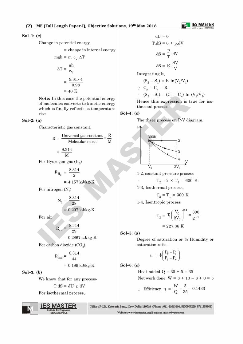
Sol–4: (c)The three process on P-V diagram.
300K1 2
3
4
2V0V0
V
P
1-2, constant pressure process T2 = 2 × T1 = 600 K1-3, Isothermal process,
T2 = T1 = 300 K1-4, Isentropic process
T2 =0.4
01 0.4
0
V 300T =2V 2
= 227.36 KSol–5: (a)
Degree of saturation or % Humidity orsaturation ratio.
= b s
b v
P PP P
Sol–6: (c)
Heat added Q = 30 + 5 = 35Net work done W = 3 + 10 – 8 + 0 = 5
Efficiency = 5 0.1433= =35WQ
IES M
ASTER
(3) Test-27 (Full Length Paper-I), Objective Solutions, 19th May 2016
Sol–7: (d)
For A–B, V T
P = constantFor B–C, V = constantFor C–A, T = constant
PV = constantSol–8: (d)
Since the chamber is rigid, so volume isconstant,
hence work done W = 0
The chamber is insulated,
So, Q = 0
From first law of thermodynamics,
Q = dU + W
dU = 0Sol–9: (c)
The amount of entropy generated
Sgen =
1 2
1 2
T TQ
T T
= 1600 ×
800 400800 400 = 2 kJ/k
Sol–10: (a)Earlier, temperature T1 = 27°C = 300 KPressure p1 = 2 barVolume V1 = 30 litresAssuming the volume to remain constantat temperature T2 = – 3°C = 270 K
Hence, 1
1
pT = 2
2
pT
2
300 = 2p270
p2 = 1.8 barSol–11: (d)
1. Surging is cyclic fluctuations of pres-sure and flow rate. This happenswhen the compressor is operatingaway from designed point.
2. When flow rate is low the axial flowvelocity reduces which increases
blade inlet angle. Under this condi-tion the air flow is not able to followblade contour and flow separates outfrom blade called stalling. So it is alocal phenomenon.
Sol–12: (c)The general expression for equivalentemissivity in enclosure and equivalentsystem.
e =1
1 2 2
1A1 1 1A
A. Infinite parallel planes i.e. A1 = A2
e =
1 2
11 1 1
B. Body 1 completely enclosed in body 2but 1 is very small i.e. A1 << A2
e = 1
1 2
1 =1 10 1
C. Two small Gray body exchanging ra-diation is given separately as,
e = 1 2
D. Two concentric cylinders of largelength,
e =1
1 2 2
1A1 1 1A
Sol–13: (c)
P
STT
= CP
andv
STT
= CV
Cp – CV = RSol–14: (a)
Assumption of Carnot cycle(i) The walls of piston and cylinder are
considered as perfect insulators ofheat.
(ii) The cylinder head is so arranged thatit can be a perfect heat conductor or
IES M
ASTER
(4) ME (Full Length Paper-I), Objective Solutions, 19th May 2016
perfect heat insulator.(iii) The transfer of heat does not affect
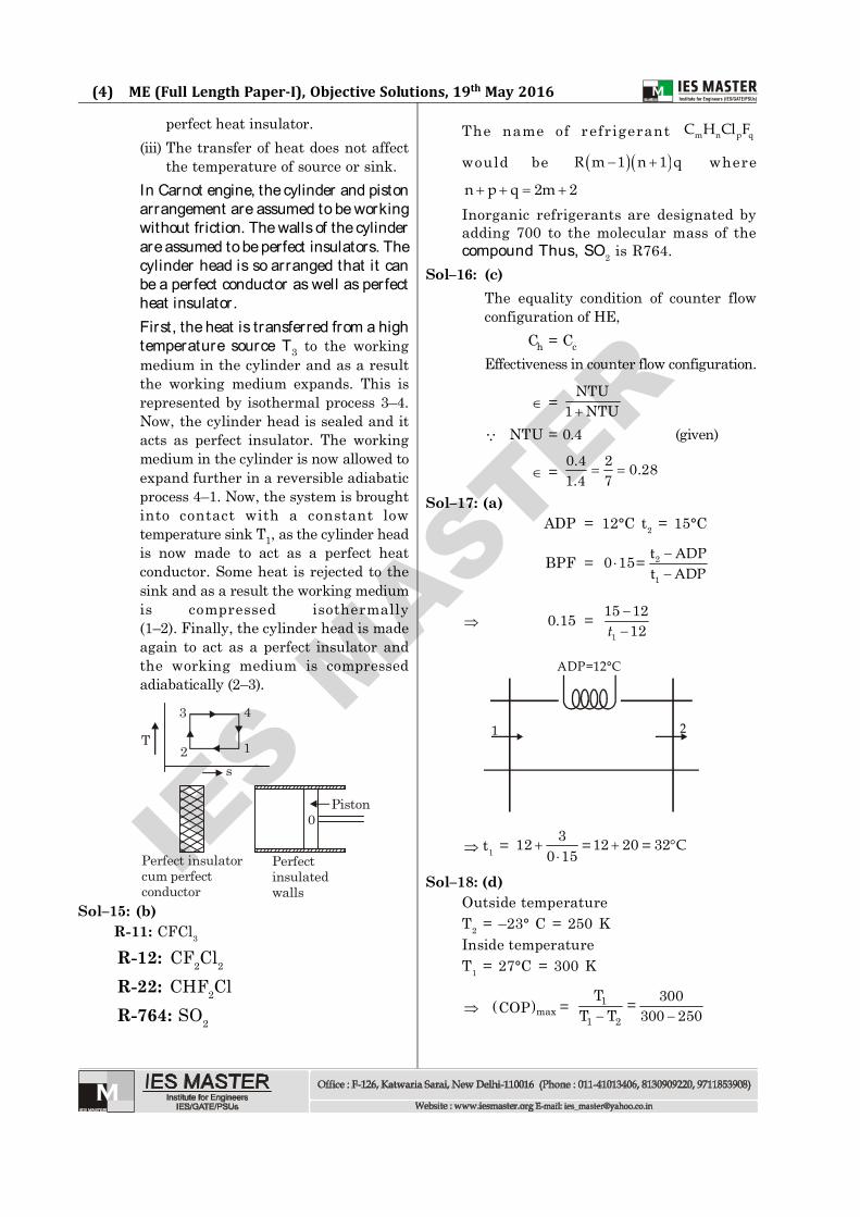
the temperature of source or sink.In Carnot engine, the cylinder and pistonarrangement are assumed to be workingwithout friction. The walls of the cylinderare assumed to be perfect insulators. Thecylinder head is so arranged that it canbe a perfect conductor as well as perfectheat insulator.First, the heat is transferred from a hightemperature source T3 to the workingmedium in the cylinder and as a resultthe working medium expands. This isrepresented by isothermal process 3–4.Now, the cylinder head is sealed and itacts as perfect insulator. The workingmedium in the cylinder is now allowed toexpand further in a reversible adiabaticprocess 4–1. Now, the system is broughtinto contact with a constant lowtemperature sink T1, as the cylinder headis now made to act as a perfect heatconductor. Some heat is rejected to thesink and as a result the working mediumis compressed isothermally(1–2). Finally, the cylinder head is madeagain to act as a perfect insulator andthe working medium is compressedadiabatically (2–3).
T
s
3 4
2 1
Perfect insulatorcum perfectconductor
Piston0
Perfectinsulatedwalls
Sol–15: (b)R-11: CFCl3
R-12: CF2Cl2
R-22: CHF2ClR-764: SO2
The name of refrigerant m n p qC H Cl F
would be 1 1R m n q where
2 2n p q m
Inorganic refrigerants are designated byadding 700 to the molecular mass of thecompound Thus, SO2 is R764.
Sol–16: (c)The equality condition of counter flowconfiguration of HE,
Ch = Cc
Effectiveness in counter flow configuration.
=NTU
1 NTU
NTU = 0.4 (given)
=0.4 2 0.281.4 7
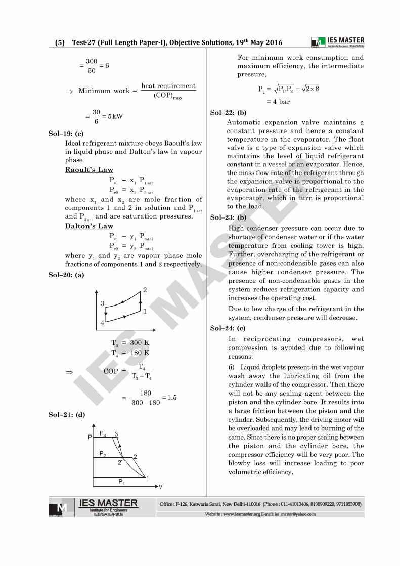
Sol–17: (a)ADP = 12°C t2 = 15°C
BPF = 2
10 15=
t ADPt ADP
0.15 =1
15 1212t
ADP=12°C
1 2
t1 = 312 12 20 32= =0 15
C
Sol–18: (d)Outside temperature T2 = –23° C = 250 KInside temperatureT1 = 27°C = 300 K
maxCOP = 1
1 2
T 300=T T 300 250
IES M
ASTER
(5) Test-27 (Full Length Paper-I), Objective Solutions, 19th May 2016
300 6= =50
Minimum work = max
heat requirement(COP)
= 30 5kW=6
Sol–19: (c)Ideal refrigerant mixture obeys Raoult’s lawin liquid phase and Dalton’s law in vapourphaseRaoult’s Law
Pv1 = x1 P1 sat
Pv2 = x2 P2 sat
where x1 and x2 are mole fraction ofcomponents 1 and 2 in solution and P1 satand P2 sat and are saturation pressures.Dalton’s Law
Pv1 = y1 Ptotal
Pv2 = y2 Ptotal
where y1 and y2 are vapour phase molefractions of components 1 and 2 respectively.
Sol–20: (a)
4
2
31
T3 = 300 KT4 = 180 K
COP = 4
3 4
TT T
= 180 1.5=300 180
Sol–21: (d)
P P3 3
P2 2
P11
V
2
For minimum work consumption andmaximum efficiency, the intermediatepressure,
P2 = 1 2P .P 2 8
= 4 barSol–22: (b)
Automatic expansion valve maintains aconstant pressure and hence a constanttemperature in the evaporator. The floatvalve is a type of expansion valve whichmaintains the level of liquid refrigerantconstant in a vessel or an evaporator. Hence,the mass flow rate of the refrigerant throughthe expansion valve is proportional to theevaporation rate of the refrigerant in theevaporator, which in turn is proportionalto the load.
Sol–23: (b)High condenser pressure can occur due toshortage of condenser water or if the watertemperature from cooling tower is high.Further, overcharging of the refrigerant orpresence of non-condensible gases can alsocause higher condenser pressure. Thepresence of non-condensable gases in thesystem reduces refrigeration capacity andincreases the operating cost.Due to low charge of the refrigerant in thesystem, condenser pressure will decrease.
Sol–24: (c)In reciprocating compressors, wetcompression is avoided due to followingreasons:(i) Liquid droplets present in the wet vapourwash away the lubricating oil from thecylinder walls of the compressor. Then therewill not be any sealing agent between thepiston and the cylinder bore. It results intoa large friction between the piston and thecylinder. Subsequently, the driving motor willbe overloaded and may lead to burning of thesame. Since there is no proper sealing betweenthe piston and the cylinder bore, thecompressor efficiency will be very poor. Theblowby loss will increase loading to poorvolumetric efficiency.
IES M
ASTER
(6) ME (Full Length Paper-I), Objective Solutions, 19th May 2016
(ii) Liquid droplets in the refrigerant wouldenter the compressor and damage thevalves and other moving parts.Dry compression is preferred over wetcompression since it gives highvolumetric efficiency and the mechanicalefficiency of the compressor is increasedwith less chance of damage to it.
Sol–25: (b)Dew point temperature is the saturationtemperature corresponding to the partialpressure of water vapour in air, which inturn depends on the mass fraction of thewater vapour in air. In the closed chamber,there is no addition or removal of moisturewhile heating, hence dew point will notchange. Further it is clear that dew pointtemperature is an indication of the moisturecontent of air.In spray humidification process, the enthalpyof air will increase.
1
2p2dt
p2dt
2wt
1wt
As relative humidity decreases from 1 to point2 in the psychrometric chart,
1 p1w dt t < 2 p2w dt t
Sol–26: (b)COP of hermetically sealed compressorbased system is lower than that of the opencompressor based systems since a part ofthe refrigeration effect is lost in cooling themotor and the compressor. Thus, hermeticcompressors are used where efficiency isnot as important as customer convenience.
Sol–27: (b)Refrigerating effect
= h1 – h4
= 1800–75=105 KJ/Kg1 ton of refrigeration = 210 kJ/min m × RE = 210
m = 210 kJ/min 2 kg/min=105 kJ/kg
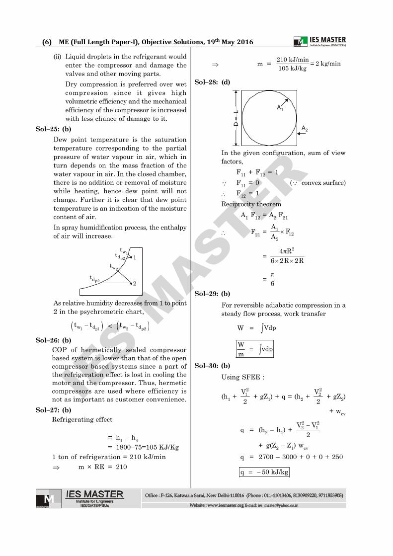
Sol–28: (d)
A1
A2
D =
L
In the given configuration, sum of viewfactors,
F11 + F12 = 1 F11 = 0 ( convex surface) F12 = 1Reciprocity theorem
A1 F12 = A2 F21
F21 = 112
2
A FA
=24 R
6 2R 2R
= 6
Sol–29: (b)For reversible adiabatic compression in asteady flow process, work transfer
W = Vdp
W vdpm
Sol–30: (b)Using SFEE :
(h1 + 21V2
+ gZ1) + q = (h2 + 22V
2 + gZ2)
+ wcv
q = (h2 – h1) + 2 22 1V V
2
+ g(Z2 – Z1) wcv
q = 2700 – 3000 + 0 + 0 + 250
q 50 kJ/kg
IES M
ASTER
(7) Test-27 (Full Length Paper-I), Objective Solutions, 19th May 2016
–ve sign shows heat transfer from tur-bine casing to surrounding.
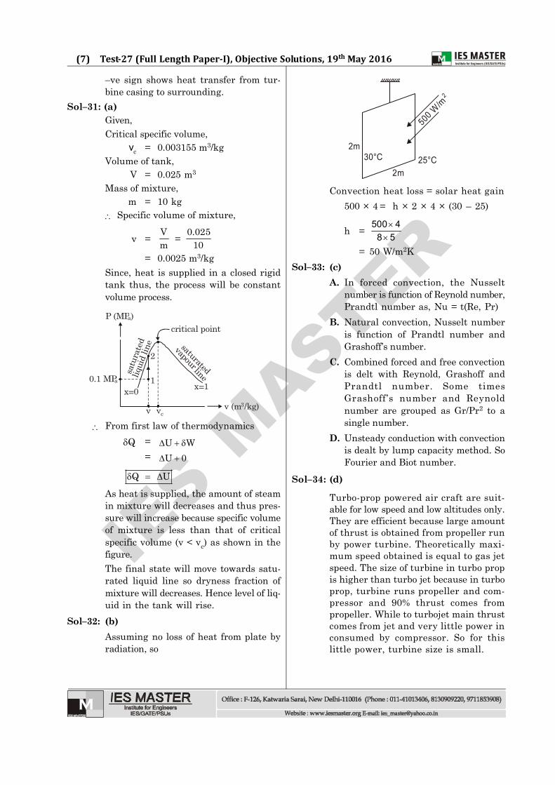
Sol–31: (a)Given,Critical specific volume,
vc = 0.003155 m3/kgVolume of tank,
V = 0.025 m3
Mass of mixture,m = 10 kg
Specific volume of mixture,
v = Vm = 0.025
10= 0.0025 m3/kg
Since, heat is supplied in a closed rigidtank thus, the process will be constantvolume process.
saturated
vapour linesatu
rate
d liq
uid
line
x=0 x=1
v vc
critical point
1
2
0.1 MPa
v (m /kg)3
P (MPa)
From first law of thermodynamicsQ = U W
= U 0
Q U
As heat is supplied, the amount of steamin mixture will decreases and thus pres-sure will increase because specific volumeof mixture is less than that of criticalspecific volume (v < vc) as shown in thefigure.The final state will move towards satu-rated liquid line so dryness fraction ofmixture will decreases. Hence level of liq-uid in the tank will rise.
Sol–32: (b)Assuming no loss of heat from plate byradiation, so
500 W
/m2
30°C
2m25°C
2m
Convection heat loss = solar heat gain500 × 4 = h × 2 × 4 × (30 – 25)
h = 500 48 5
= 50 W/m2KSol–33: (c)
A. In forced convection, the Nusseltnumber is function of Reynold number,Prandtl number as, Nu = t(Re, Pr)
B. Natural convection, Nusselt numberis function of Prandtl number andGrashoff’s number.
C. Combined forced and free convectionis delt with Reynold, Grashoff andPrandtl number. Some timesGrashoff’s number and Reynoldnumber are grouped as Gr/Pr2 to asingle number.
D. Unsteady conduction with convectionis dealt by lump capacity method. SoFourier and Biot number.
Sol–34: (d)
Turbo-prop powered air craft are suit-able for low speed and low altitudes only.They are efficient because large amountof thrust is obtained from propeller runby power turbine. Theoretically maxi-mum speed obtained is equal to gas jetspeed. The size of turbine in turbo propis higher than turbo jet because in turboprop, turbine runs propeller and com-pressor and 90% thrust comes frompropeller. While to turbojet main thrustcomes from jet and very little power inconsumed by compressor. So for thislittle power, turbine size is small.
IES M
ASTER
(8) ME (Full Length Paper-I), Objective Solutions, 19th May 2016
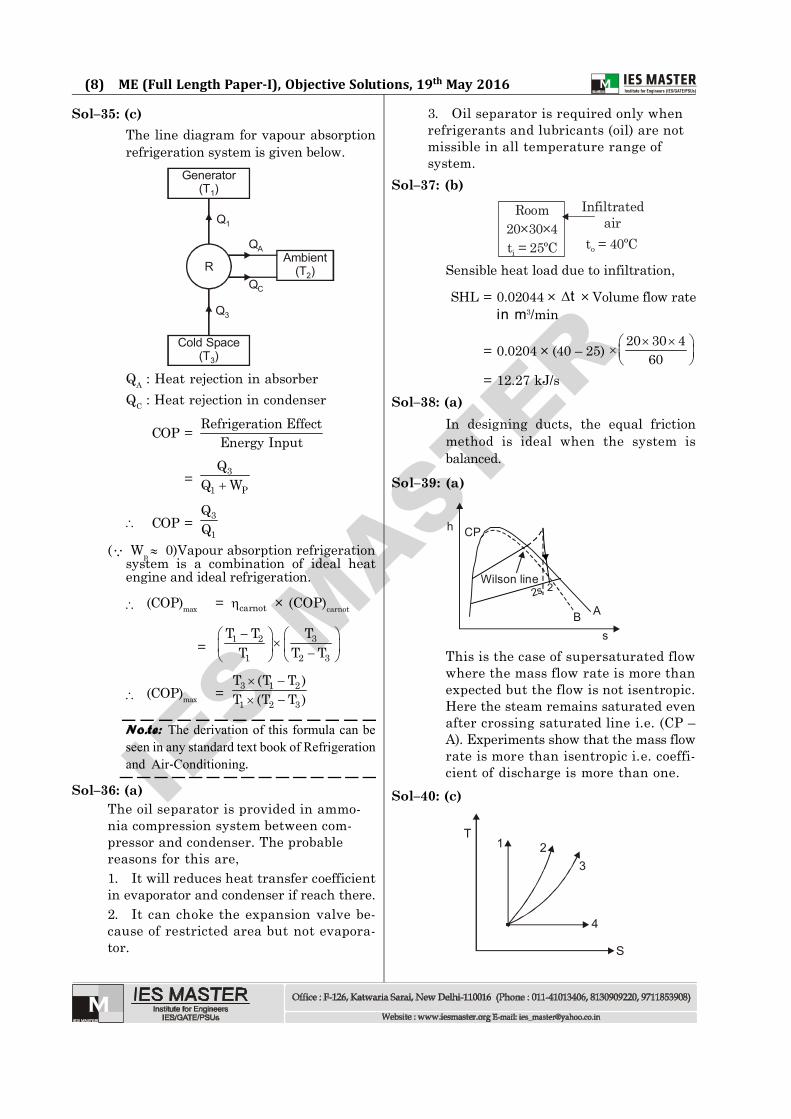
Sol–35: (c)The line diagram for vapour absorptionrefrigeration system is given below.
Q1
Q3
Generator(T )1
R
Cold Space(T )3
Ambient(T )2
QA
QC
QA : Heat rejection in absorberQC : Heat rejection in condenser
COP = Refrigeration EffectEnergy Input
= 3
1 P
QQ W
COP = 3
1
( Wp 0)Vapour absorption refrigerationsystem is a combination of ideal heatengine and ideal refrigeration.
(COP)max = carnot × (COP)carnot
= 31 2
1 2 3
TT TT T T
(COP)max = 3 1 2
1 2 3
T (T T )T (T T )
No.te: The derivation of this formula can be
seen in any standard text book of Refrigeration
and Air-Conditioning.
Sol–36: (a)The oil separator is provided in ammo-nia compression system between com-pressor and condenser. The probablereasons for this are,1. It will reduces heat transfer coefficientin evaporator and condenser if reach there.2. It can choke the expansion valve be-cause of restricted area but not evapora-tor.
3. Oil separator is required only whenrefrigerants and lubricants (oil) are notmissible in all temperature range ofsystem.
Sol–37: (b)
Room20×30×4t = 25ºCi
Infiltratedair
t = 40ºCo
Sensible heat load due to infiltration,
SHL = 0.02044 × t × Volume flow ratein m3/min
= 0.0204 × (40 – 25) 20 30 4
60
= 12.27 kJ/s
Sol–38: (a)In designing ducts, the equal frictionmethod is ideal when the system isbalanced.
Sol–39: (a)
h
A
CP
Bs
Wilson line22s
This is the case of supersaturated flowwhere the mass flow rate is more thanexpected but the flow is not isentropic.Here the steam remains saturated evenafter crossing saturated line i.e. (CP –A). Experiments show that the mass flowrate is more than isentropic i.e. coeffi-cient of discharge is more than one.
Sol–40: (c)
T1
4
S
23
IES M
ASTER
(9) Test-27 (Full Length Paper-I), Objective Solutions, 19th May 2016
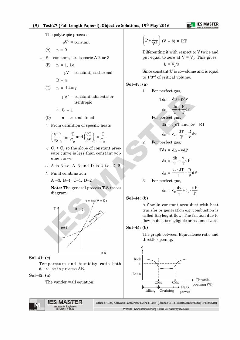
The polytropic process–
pVn = constant
(A) n = 0
P = constant, i.e. Isobaric A-2 or 3(B) n = 1, i.e.
pV = constant, isothermal
B – 4
(C) n = 1.4 .=
pV = constant adiabatic orisentropic
C – 1
(D) n = undefined From definition of specific heats
v
TS
= pp p
T T Tand =C S C
Cp > Cv so the slope of constant pres-sure curve is less than constant vol-ume curve.
A is 3 i.e. A–3 and D is 2 i.e. D–2 Final combination
A –3, B–4, C–1, D–2Note: The general process T-S tracesdiagram
T
n=1
s
n=0 (
P=C)n =
n V C=( )=
Sol–41: (c)Temperature and humidity ratio bothdecrease in process AB.
Sol–42: (a)The vander wall equation,
2aP
V
(V – b) = RT
Differenting it with respect to V twice andput equal to zero at V = Vc. This gives
b = Vc/3Since constant ‘b’ is co-volume and is equalto 1/3rd of critical volume.
Sol–43: (a)1. For perfect gas,
Tds = du pdv
ds = du P dvT T
For perfect gas,dh = cpdT and =pv RT
ds = vdT Rc dvT v
2. For perfect gas,
Tds = dh vdP
ds = dh v dPT T
ds = pc dT R dPT P
3. For perfect gas,
ds = p vdv dPc cv P
Sol–44: (b)A flow in constant area duct with heattransfer or generation e.g. combustion iscalled Rayleight flow. The friction due toflow in duct is negligible or assumed zero.
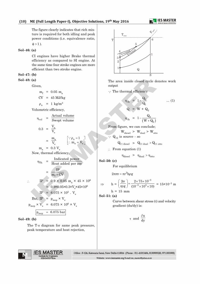
Sol–45: (b)The graph between Equivalence ratio andthrottle opening.
20% 80% Throttleopening (%)
CruisingIdlingPeakpower
Rich
Lean
1
IES M
ASTER
(10) ME (Full Length Paper-I), Objective Solutions, 19th May 2016
The figure clearly indicates that rich mix-ture is required for both idling and peakpower conditions (i.e. equivalence ratio,
1 ).Sol–46: (a)
CI engines have higher Brake thermalefficiency as compared to SI engine. Atthe same time four stroke engines are moreefficient than two stroke engine.
Sol–47: (b)Sol–48: (a)
Given,mf = 0.05 ma
CV = 45 MJ/kg
a = 1 kg/m3
Volumetric efficiency,
vol =Actual volumeSwept volume
0.3 = a
s
VV
= a
s
mV
aa a
1m V
ma = 0.3 VsNow, thermal efficiency,
Th = Indicated powerHeat added per sec
=f
IPm CV
IP = 0.9 × 0.05 ma × 45 × 106
= 0.9×0.05×0.3×Vs×45×106
IP = 6.075 × 10⁵ . Vs
But, IP = pmep × Vs
pmep × Vs = 6.075 × 10⁶ × Vs
mepp 6.075 bar
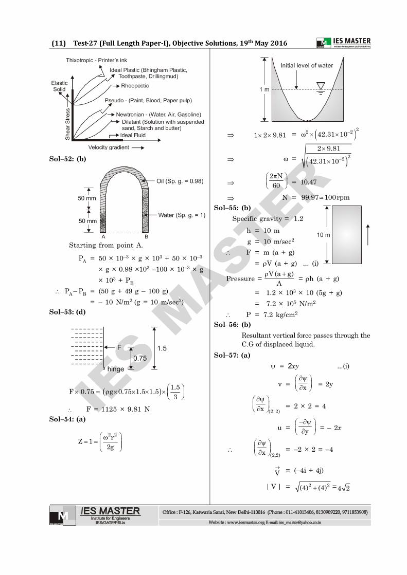
Sol–49: (b)
The T-s diagram for same peak pressure,peak temperature and heat rejection,
Tmax
1
23
4
56
1
Q
S
T
P max
V=constV=const
The area inside closed cycle denotes workoutput The thermal efficiency
th = 2
1
Q1Q
... (1)
Q1 = W + Q2
th =
2
2
Q1W Q
From figure, we can conclude;Wdiesel > Wdual > Wotto
Q12 is source - so
11 dieselQ > 11 dual 11 ottoQ Q
From equation (1)diesel > dual otto
Sol–50: (c)For equilibrium
22 r r h g
h = 3
3 32 2 75 10r g (10 10 10)
= 15×10–3 m
h = 15 mmSol–51: (a)
Curve between shear stress () and velocitygradient (du/dy) is:
and u
dy
IES M
ASTER
(11) Test-27 (Full Length Paper-I), Objective Solutions, 19th May 2016
Shea
r Stre
ss
Velocity gradient
Thixotropic - Printer’s ink
Ideal Plastic (Bhingham Plastic,Toothpaste, Drillingmud)
Rheopectic
Pseudo - (Paint, Blood, Paper pulp)
Newtronian - (Water, Air, Gasoline)Dilatant (Solution with suspendedsand, Starch and butter)
Ideal Fluid
ElasticSolid
Sol–52: (b)
Oil (Sp. g. = 0.98)
Water (Sp. g. = 1)
A B
50 mm
50 mm
Starting from point A.
PA = 50 × 10–3 × g × 103 + 50 × 10–3
× g × 0.98 ×10³ –100 × 10–3 × g× 103 + PB
PA – PB = (50 g + 49 g – 100 g)= – 10 N/m2 (g = 10 m/sec2)
Sol–53: (d)
F
hinge0.75
1.5
1.5F 0.75 g 0.75 1.5 1.53
F = 1125 × 9.81 NSol–54: (a)
2 2rZ 12g
Initial level of water
1 m
1 2 9.81 = 22 242.31 10
= 22
2 9.81
42.31 10
2 N60
= 10.47
N = 99.97 100rpmSol–55: (b)
Specific gravity = 1.2
10 m h = 10 mg = 10 m/sec2
F = m (a + g)= V (a + g) ... (i)
Pressure = V(a g)A
= h (a + g)
= 1.2 × 103 × 10 (5g + g)= 7.2 × 10⁵ N/m2
P = 7.2 kg/cm2
Sol–56: (b)Resultant vertical force passes through theC.G of displaced liquid.
Sol–57: (a) = 2xy ...(i)
v = x
= 2y
(2, 2)x
= 2 × 2 = 4
u =–
y
= – 2x
(2,2)x
= –2 × 2 = –4
V = (–4i + 4j)
| V | = 2 2(4) (4) =4 2
IES M
ASTER
(12) ME (Full Length Paper-I), Objective Solutions, 19th May 2016
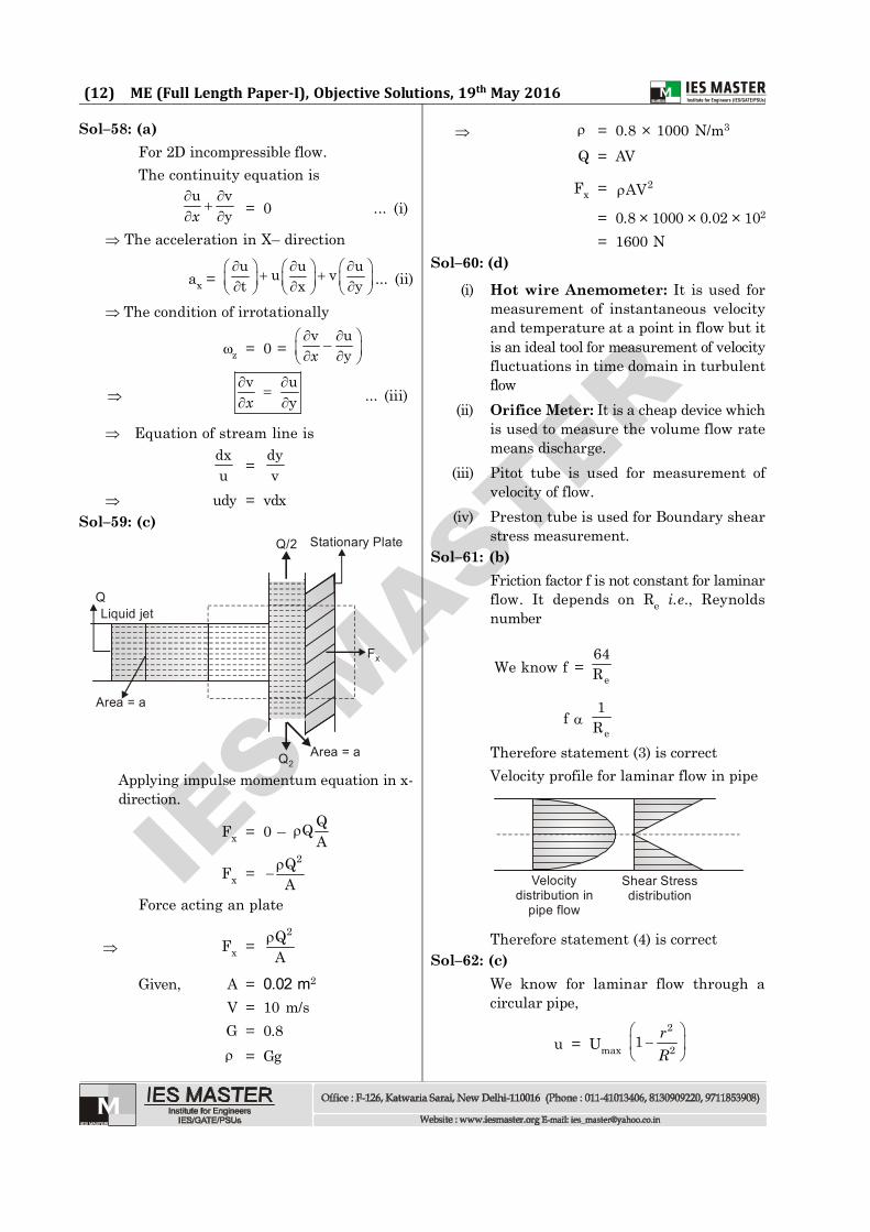
Sol–58: (a)For 2D incompressible flow.The continuity equation is
u vy
x = 0 ... (i)
The acceleration in X– direction
ax = u u uu vt x y
... (ii)
The condition of irrotationally
z = 0 = v u–
y
x
v u
y
x ... (iii)
Equation of stream line isdxu = dy
v udy = vdx
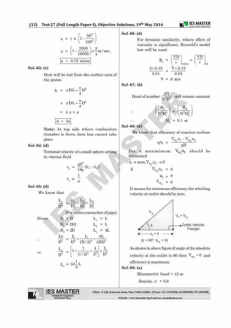
Sol–59: (c)
Fx
Area = aQ2
Area = a
QLiquid jet
Q/2 Stationary Plate
Applying impulse momentum equation in x-direction.
Fx = 0 – QQA
Fx =2Q
A
Force acting an plate
Fx =2Q
A
Given, A = 0.02 m2
V = 10 m/sG = 0.8 = Gg
= 0.8 × 1000 N/m3
Q = AV
Fx = 2AV
= 0.8 × 1000 × 0.02 × 102
= 1600 NSol–60: (d)
(i) Hot wire Anemometer: It is used formeasurement of instantaneous velocityand temperature at a point in flow but itis an ideal tool for measurement of velocityfluctuations in time domain in turbulentflow
(ii) Orifice Meter: It is a cheap device whichis used to measure the volume flow ratemeans discharge.
(iii) Pitot tube is used for measurement ofvelocity of flow.
(iv) Preston tube is used for Boundary shearstress measurement.
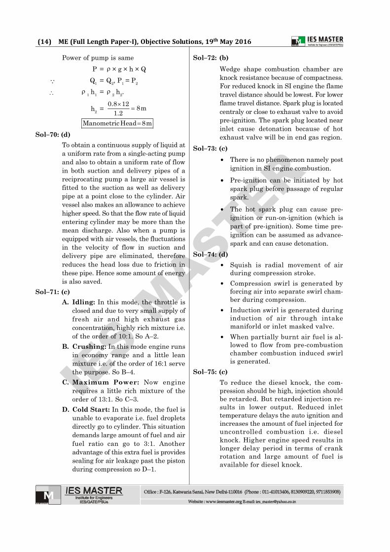
Sol–61: (b)Friction factor f is not constant for laminarflow. It depends on Re i.e., Reynoldsnumber
We know f =e
64R
f e
1R
Therefore statement (3) is correctVelocity profile for laminar flow in pipe
Velocitydistribution in
pipe flow
Shear Stressdistribution
Therefore statement (4) is correctSol–62: (c)
We know for laminar flow through acircular pipe,
u = Umax 2
21 rR
IES M
ASTER
(13) Test-27 (Full Length Paper-I), Objective Solutions, 19th May 2016
u = 1 × 2
2501
100
u =25001
10000
= 3 m / sec.4
u 0.75 m/sec
Sol–63: (c)Heat will be lost from the surface area ofthe piston
A = 2DL D4
= 2DL D4
= 4 +
A 5
Note: At top side where combustionchmaber is there, heat loss cannot takeplace.
Sol–64: (d)Terminal velocity of a small sphere settingin viscous fluid
vt =2
s ugd ( )18
vt 1
Sol–65: (d)We know that
e5
LD = 31 2
5 5 51 2 3
LL LD D D
[For series connection of pipe] Given, D1 = D L1 = L
D2 = D/2 L2 = LD3 = 2D L3 = 4L
5LeD = 5 5 5
L L 4LD (D / 2) (2D)
e5
LD = 5 5 5
1 4 L1(1 / 2) 2 D
Le = 133 L8
Sol–66: (d)For dynamic similarity, where effect ofviscosity is significant, Reynold’s modellaw will be used.
Re =water
VD
= oil
VD
2 0.150.01 = V 0.15
0.03
V = 6 m/sSol–67: (b)
Head of number 2 2gH
N D will remain constant
1
2 21
HN D
= 22 2
2
HN D
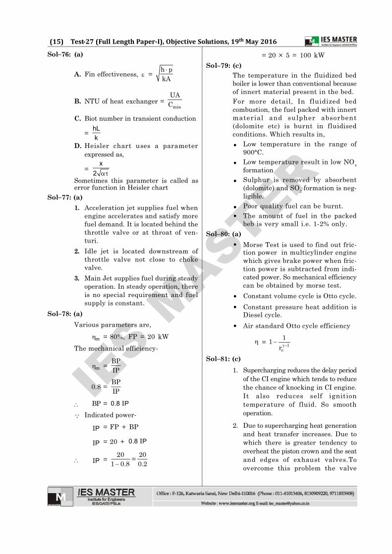
H2 = 8.1 mSol–68: (d)
We know that efficiency of reaction turbine
% = 1 2w 1 w 2V u V ugH
For maximimum. 2w 2V u should beminimized
2w 2max,V u 0
if 2w 2V u = 0u2 0
2wV = 0It means for miximum efficiency the whirlingvelocity at outlet should be zero.
Vr2 V = V 2 f2
Outlet VelocityTriangle
u = 42
( = 90º, V = 0) w2
As shown in above figure if angle of the absolute
velocity at the outlet is 90 then 2wV 0 andefficiency is maximum.
Sol–69: (a)Manometric head = 12 m
Density, = 0.8
IES M
ASTER
(14) ME (Full Length Paper-I), Objective Solutions, 19th May 2016
Power of pump is sameP = × g × h × Q
Q1 = Q2, P1 = P2
1 h1 =
2 h2.
h2 = 0.8 12 8m1.2
ManometricHead 8m
Sol–70: (d)To obtain a continuous supply of liquid ata uniform rate from a single-acting pumpand also to obtain a uniform rate of flowin both suction and delivery pipes of areciprocating pump a large air vessel isfitted to the suction as well as deliverypipe at a point close to the cylinder. Airvessel also makes an allowance to achievehigher speed. So that the flow rate of liquidentering cylinder may be more than themean discharge. Also when a pump isequipped with air vessels, the fluctuationsin the velocity of flow in suction anddelivery pipe are eliminated, thereforereduces the head loss due to friction inthese pipe. Hence some amount of energyis also saved.
Sol–71: (c)A. Idling: In this mode, the throttle is
closed and due to very small supply offresh air and high exhaust gasconcentration, highly rich mixture i.e.of the order of 10:1. So A–2.
B. Crushing: In this mode engine runsin economy range and a little leanmixture i.e. of the order of 16:1 servethe purpose. So B–4.
C. Maximum Power: Now enginerequires a little rich mixture of theorder of 13:1. So C–3.
D. Cold Start: In this mode, the fuel isunable to evaporate i.e. fuel dropletsdirectly go to cylinder. This situationdemands large amount of fuel and airfuel ratio can go to 3:1. Anotheradvantage of this extra fuel is providessealing for air leakage past the pistonduring compression so D–1.
Sol–72: (b)Wedge shape combustion chamber areknock resistance because of compactness.For reduced knock in SI engine the flametravel distance should be lowest. For lowerflame travel distance. Spark plug is locatedcentraly or close to exhaust valve to avoidpre-ignition. The spark plug located nearinlet cause detonation because of hotexhaust valve will be in end gas region.
Sol–73: (c) There is no phenomenon namely post
ignition in SI engine combustion. Pre-ignition can be initiated by hot
spark plug before passage of regularspark.
The hot spark plug can cause pre-ignition or run-on-ignition (which ispart of pre-ignition). Some time pre-ignition can be assumed as advance-spark and can cause detonation.
Sol–74: (d) Squish is radial movement of air
during compression stroke. Compression swirl is generated by
forcing air into separate swirl cham-ber during compression.
Induction swirl is generated duringinduction of air through intakemaniforld or inlet masked valve.
When partially burnt air fuel is al-lowed to flow from pre-combustionchamber combustion induced swirlis generated.
Sol–75: (c)To reduce the diesel knock, the com-pression should be high, injection shouldbe retarded. But retarded injection re-sults in lower output. Reduced inlettemperature delays the auto ignition andincreases the amount of fuel injected foruncontrolled combustion i.e. dieselknock. Higher engine speed results inlonger delay period in terms of crankrotation and large amount of fuel isavailable for diesel knock.
IES M
ASTER
(15) Test-27 (Full Length Paper-I), Objective Solutions, 19th May 2016
Sol–76: (a)
A. Fin effectiveness, = h pkA
B. NTU of heat exchanger = min
UAC
C. Biot number in transient conduction
= hLk
D. Heisler chart uses a parameterexpressed as,
= x
2 Sometimes this parameter is called aserror function in Heisler chart
Sol–77: (a)1. Acceleration jet supplies fuel when
engine accelerates and satisfy morefuel demand. It is located behind thethrottle valve or at throat of ven-turi.
2. Idle jet is located downstream ofthrottle valve not close to chokevalve.
3. Main Jet supplies fuel during steadyoperation. In steady operation, thereis no special requirement and fuelsupply is constant.
Sol–78: (a)Various parameters are,
m = 80%, FP = 20 kWThe mechanical efficiency-
m = BPIP
0.8 = BPIP
BP = 0.8 PI
Indicated power-
PI = FP + BP
PI = 20 + 0.8 PI
PI =20 20=
1 0.8 0.2
= 20 × 5 = 100 kWSol–79: (c)
The temperature in the fluidized bedboiler is lower than conventional becauseof innert material present in the bed.For more detail, In fluidized bedcombustion, the fuel packed with innertmaterial and su lpher absorbent(dolomite etc) is burnt in fluidisedconditions. Which results in, Low temperature in the range of
900°C. Low temperature result in low NOx
formation Sulphur is removed by absorbent
(dolomite) and SO2 formation is neg-ligible.
Poor quality fuel can be burnt. The amount of fuel in the packed
beb is very small i.e. 1-2% only.Sol–80: (a)
Morse Test is used to find out fric-tion power in multicylinder enginewhich gives brake power when fric-tion power is subtracted from indi-cated power. So mechanical efficiencycan be obtained by morse test.
Constant volume cycle is Otto cycle. Constant pressure heat addition is
Diesel cycle. Air standard Otto cycle efficiency
= 1c
11r
Sol–81: (c)1. Supercharging reduces the delay period
of the CI engine which tends to reducethe chance of knocking in CI engine.It also reduces self ignitiontemperature of fluid. So smoothoperation.
2. Due to supercharging heat generationand heat transfer increases. Due towhich there is greater tendency tooverheat the piston crown and the seatand edges of exhaust valves.Toovercome this problem the valve
IES M
ASTER
(16) ME (Full Length Paper-I), Objective Solutions, 19th May 2016
overlap is greater.
3. Supercharging for CI engine is reachedby thermal and mechanical loadingdue to above reason.
Sol–82: (d)Any method which reduces peak tem-perature during combustion will reduceoxides of nitrogen in exhaust.1. Decrease in compression ratio re-
duces peak temperature so NOxemission.
2. Exhaust gas recirculation also re-duces peak temperature by absorb-ing some heat during combustion.
3. 5% lean mixture increases NOx byhaving peak temperature and suffi-cient amount of oxygen.
4. Oxidation catalysts controls HC andCO.
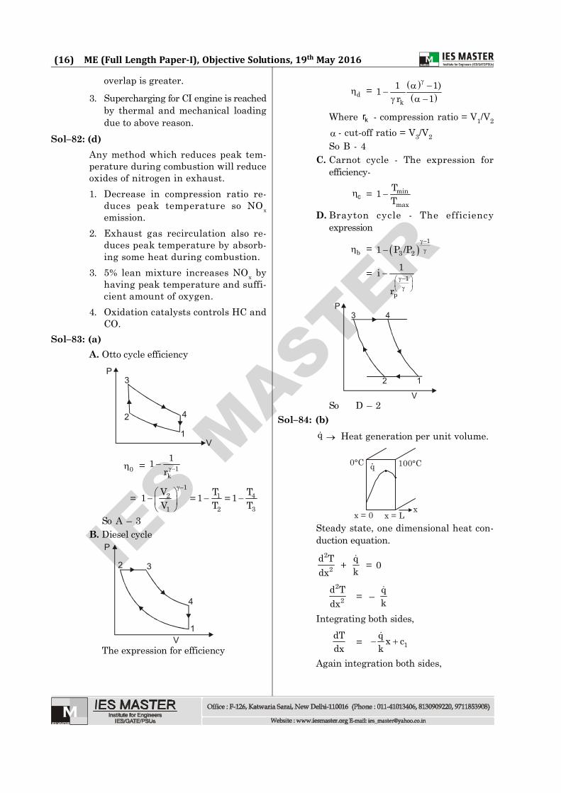
Sol–83: (a)A. Otto cycle efficiency
3P
2
1
4
V
0 = 1k
11r
= 1
2 1 4
1 2 3
V T T1 1 1= =V T T
So A – 3B. Diesel cycle
P
V
32
4
1
The expression for efficiency
d = k
1 1)1r 1
Where kr - compression ratio = V1/V2
- cut-off ratio = V3/V2So B - 4
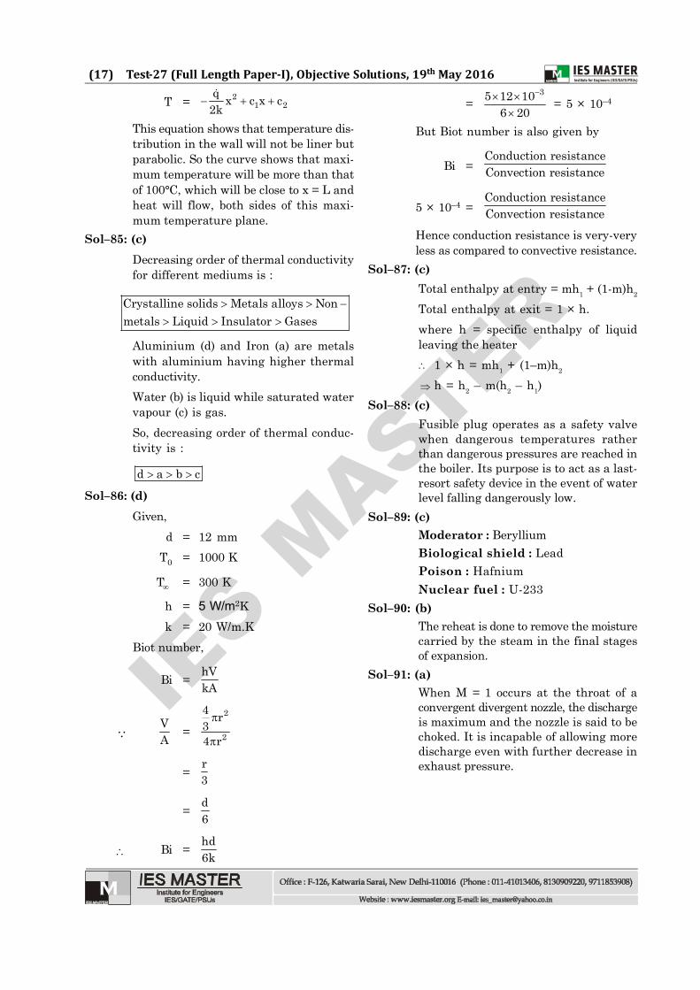
C. Carnot cycle - The expression forefficiency-
c = min
max
T1T
D. Brayton cycle - The efficiencyexpression
b = 1
3 21 P /P
= 1
p
1i
r
P3 4
2 1
VSo D – 2
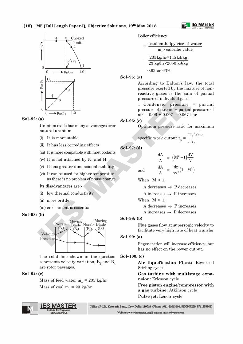
Sol–84: (b)q Heat generation per unit volume.
q 100°C0°C
xx = 0 x = LSteady state, one dimensional heat con-duction equation.
2
2d Tdx
+ qk
= 0
2
2d Tdx
= – qk
Integrating both sides,dTdx = 1
q x ck
Again integration both sides,
IES M
ASTER
(17) Test-27 (Full Length Paper-I), Objective Solutions, 19th May 2016
T = 21 2
q x c x c2k
This equation shows that temperature dis-tribution in the wall will not be liner butparabolic. So the curve shows that maxi-mum temperature will be more than thatof 100°C, which will be close to x = L andheat will flow, both sides of this maxi-mum temperature plane.
Sol–85: (c)Decreasing order of thermal conductivityfor different mediums is :
Crystalline solids Metals alloys Nonmetals Liquid Insulator Gases
Aluminium (d) and Iron (a) are metalswith aluminium having higher thermalconductivity.Water (b) is liquid while saturated watervapour (c) is gas.So, decreasing order of thermal conduc-tivity is :
d a b c
Sol–86: (d)Given,
d = 12 mmT0 = 1000 K
T = 300 K
h = 5 W/m2Kk = 20 W/m.K
Biot number,
Bi = hVkA
VA =
2
2
4 r34 r
= r3
= d6
Bi = hd6k
=35 12 10
6 20
= 5 × 10⁻⁴
But Biot number is also given by
Bi =Conduction resistanceConvection resistance
5 × 10–4 =Conduction resistanceConvection resistance
Hence conduction resistance is very-veryless as compared to convective resistance.
Sol–87: (c)Total enthalpy at entry = mh1 + (1-m)h2
Total enthalpy at exit = 1 × h.where h = specific enthalpy of liquidleaving the heater 1 × h = mh1 + (1–m)h2
h = h2 – m(h2 – h1)Sol–88: (c)
Fusible plug operates as a safety valvewhen dangerous temperatures ratherthan dangerous pressures are reached inthe boiler. Its purpose is to act as a last-resort safety device in the event of waterlevel falling dangerously low.
Sol–89: (c)Moderator : BerylliumBiological shield : LeadPoison : HafniumNuclear fuel : U-233
Sol–90: (b)The reheat is done to remove the moisturecarried by the steam in the final stagesof expansion.
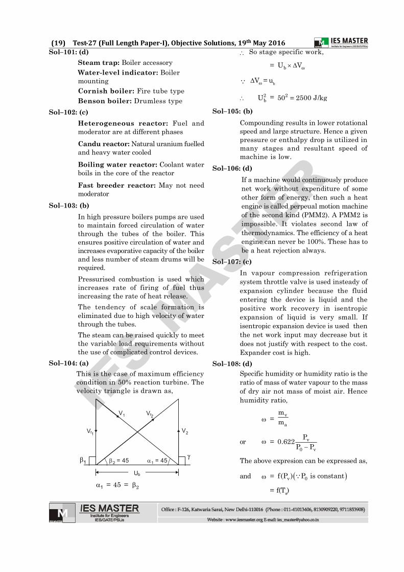
Sol–91: (a)When M = 1 occurs at the throat of aconvergent divergent nozzle, the dischargeis maximum and the nozzle is said to bechoked. It is incapable of allowing moredischarge even with further decrease inexhaust pressure.
IES M
ASTER
(18) ME (Full Length Paper-I), Objective Solutions, 19th May 2016
4 3 Chokedlimit2
100 1.0
ω/A
pB /p0
p*/p0
p E /p
0
pB /p0 1.000
34
2
1.0 1
Sol–92: (a)Uranium oxide has many advantages overnatural uranium(i) It is more stable(ii) It has less corroding effects(iii) It is more compatible with most coolants(iv) It is not attached by N2 and H2
(v) It has greater dimensional stability(vi) It can be used for higher temperature
as these is no problem of phase changeIts disadvantages are:-(i) low thermal conductivity(ii) more brittle(iii) enrichment is essential
Sol–93: (b)
VelocityPressure
Nozzle(B )1
MovingBlade(B )2
Nozzle(B )3
MovingBlade(B )4
The solid line shown in the questionrepresents velocity variation, B2 and B4are rotor passages.
Sol–94: (c)Mass of feed water mw = 205 kg/hrMass of coal mc = 23 kg/hr
Boiler efficiency
= c
total enthalpy rise of waterm calorific value
= 205kg/hr×145kJ/kg23 kg/hr×2050 kJ/kg
= 0.63 or 63%Sol–95: (a)
According to Dalton’s law, the totalpressure exerted by the mixture of non-reactive gases is the sum of partialpressure of individual gases. Condenser pressure = partialpressure of stream + partial pressure ofair = 0.06 + 0.007 = 0.067 bar
Sol–96: (c)Optimum pressure ratio for maximum
specific work output rp = 2 13
1
TT
Sol–97: (d)dAA = 2 dVM 1
V
and dAA = 2
2dp 1 Mv
When M < 1,A decreases P decreasesA increases P increases
When M > 1,A decreases P increasesA increases P decreases
Sol–98: (b)Flue gases flow at supersonic velocity tofacilitate very high rate of heat transfer
Sol–99: (a)Regeneration will increase efficiency, buthas no effect on the power output.
Sol–100: (c)Air liquefication Plant: ReversedStirling cycleGas turbine with multistage expa-nsion: Ericsson cycleFree piston engine/compressor witha gas turbine: Atkinson cyclePulse jet: Lenoir cycle
IES M
ASTER
(19) Test-27 (Full Length Paper-I), Objective Solutions, 19th May 2016Sol–101: (d)
Steam trap: Boiler accessoryWater-level indicator: BoilermountingCornish boiler: Fire tube typeBenson boiler: Drumless type
Sol–102: (c)Heterogeneous reactor: Fuel andmoderator are at different phasesCandu reactor: Natural uranium fuelledand heavy water cooledBoiling water reactor: Coolant waterboils in the core of the reactorFast breeder reactor: May not needmoderator
Sol–103: (b)In high pressure boilers pumps are usedto maintain forced circulation of waterthrough the tubes of the boiler. Thisensures positive circulation of water andincreases evaporative capacity of the boilerand less number of steam drums will berequired.Pressurised combustion is used whichincreases rate of firing of fuel thusincreasing the rate of heat release.The tendency of scale formation iseliminated due to high velocity of waterthrough the tubes.The steam can be raised quickly to meetthe variable load requirements withoutthe use of complicated control devices.
Sol–104: (a)This is the case of maximum efficiencycondition in 50% reaction turbine. Thevelocity triangle is drawn as,
2 = 45 1 = 45
Ub
V2
V1 Vr2
Vr1
1
1 = 45 = 2
So stage specific work,
= bU V
V = ub
2bU = 250 2500 J/kg=
Sol–105: (b)Compounding results in lower rotationalspeed and large structure. Hence a givenpressure or enthalpy drop is utilized inmany stages and resultant speed ofmachine is low.
Sol–106: (d)If a machine would continuously producenet work without expenditure of someother form of energy, then such a heatengine is called perpeual motion machineof the second kind (PMM2). A PMM2 isimpossible. It violates second law ofthermodynamics. The efficiency of a heatengine can never be 100%. These has tobe a heat rejection always.
Sol–107: (c)In vapour compression refrigerationsystem throttle valve is used insteady ofexpansion cylinder because the fluidentering the device is liquid and thepositive work recovery in isentropicexpansion of liquid is very small. Ifisentropic expansion device is used thenthe net work input may decrease but itdoes not justify with respect to the cost.Expander cost is high.
Sol–108: (d)Specific humidity or humidity ratio is theratio of mass of water vapour to the massof dry air not mass of moist air. Hencehumidity ratio,
= v
a
mm
or = v
0 v
P0.622P P
The above expresion can be expressed as,
and = v 0f(P ) P is constant
= f(Ts)
IES M
ASTER
(20) ME (Full Length Paper-I), Objective Solutions, 19th May 2016
So statement (II) is correct and (I) iswrong.
Sol–109: (c)Effective temperature or an index ofcomfort is a function of DBT, velocity andhumidity.
Sol–110: (d)In dropwise condensation, most of coolingsurface in exposed to heated fluid. Due tothis exposed surface, heat transfercoefficient is more in dropwisecondensation than filmwise. In film wisecondensation whole solid cooling surfaceis covered by condensate and heat transfercoefficient reduces.
Sol–111: (d)The mixture of solid, liquid and vapour ispure substance. So number of componentin mixture,
C = 1Number of phases i.e. solid, liquid andvapour, 3=From Gibb’s phase rule, degree of free-dom,
DoF = C 2
= 1 – 3 + 2 = 0So independent intrinsic property is zeroand the co-existance of all three phaseis at a particular point called ‘Triplepoint’
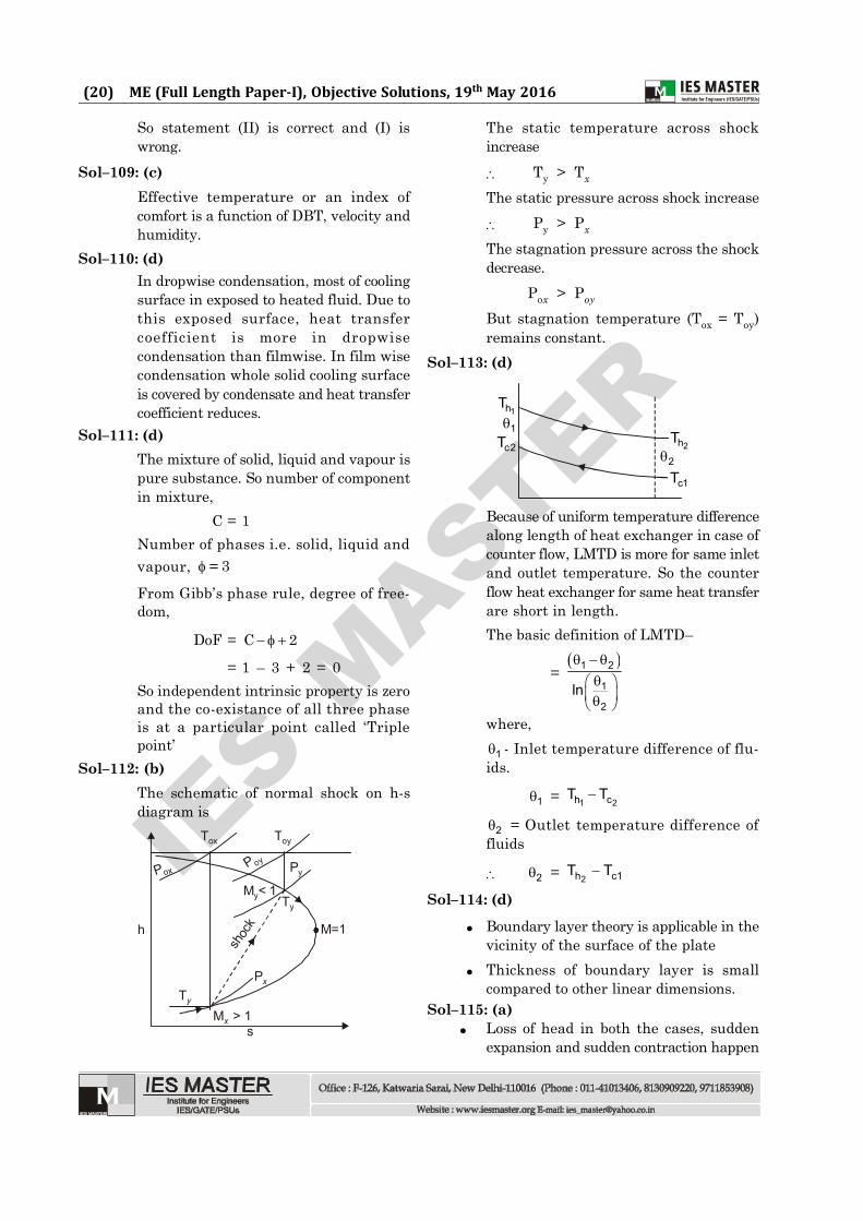
Sol–112: (b)The schematic of normal shock on h-sdiagram is
h
Pox
Tox Toy
Py
Ty
P oy
M < 1y
M=1
shoc
k
Px
Ty
sM > 1x
The static temperature across shockincrease
Ty > Tx
The static pressure across shock increase Py > Px
The stagnation pressure across the shockdecrease.
Pox > Poy
But stagnation temperature (Tox = Toy)remains constant.
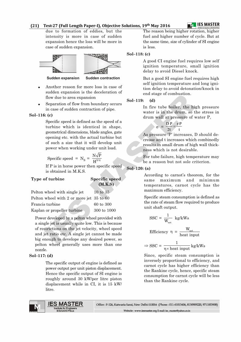
Sol–113: (d)
1hT
c2T1
c1T2
2hT
Because of uniform temperature differencealong length of heat exchanger in case ofcounter flow, LMTD is more for same inletand outlet temperature. So the counterflow heat exchanger for same heat transferare short in length.The basic definition of LMTD–
= 1 2
1
2ln
where,
1 - Inlet temperature difference of flu-ids.
1 = 1 2h cT T
2 = Outlet temperature difference offluids
2 = 2h c1T T
Sol–114: (d)
Boundary layer theory is applicable in thevicinity of the surface of the plate
Thickness of boundary layer is smallcompared to other linear dimensions.
Sol–115: (a) Loss of head in both the cases, sudden
expansion and sudden contraction happen
IES M
ASTER
(21) Test-27 (Full Length Paper-I), Objective Solutions, 19th May 2016due to formation of eddies, but theintensity is more in case of suddenexpansion hence the loss will be more incase of sudden expansion.
Sudden expansion Sudden contraction
Another reason for more loss in case ofsudden expansion is the deceleration offlow due to area expansion
Separation of flow from boundary occursin case of sudden contraction of pipe.
Sol–116: (c)Specific speed is defined as the speed of aturbine which is identical in shape,geometrical dimensions, blade angles, gateopening etc. with the actual turbine butof such a size that it will develop unitpower when working under unit load.
Specific speed = NS = 5/4N PH
If P is in horse power then specific speedis obtained in M.K.S.
Type of turbine Specific speed (M.K.S)
Pelton wheel with single jet 10 to 35Pelton wheel with 2 or more jet 35 to 60Francis turbine 60 to 300Kaplan or propeller turbine 300 to 1000
Power developed by a pelton wheel provided witha single jet is usually quite low. This is becauseof restrictions on the jet velocity, wheel speedand jet ratio etc. A single jet cannot be madebig enough to develope any desired power, sopelton wheel generally uses more than onenozzle.
Sol–117: (d)The specific output of engine is defined aspower output per unit piston displacement.Hence the specific output of SI engine isroughly around 30 kW/per litre pistondisplacement while in CI, it is 15 kW/litre.
The reason being higher rotation, higherfuel and higher number of cycle. But atthe same time, size of cylinder of SI engineis less.
Sol–118: (c)A good CI engine fuel requires low selfignition temperature, small ignitiondelay to avoid Diesel knock.But a good SI engine fuel requires highself ignition temperature and long igni-tion delay to avoid detonation/knock inend stage of combustion.
Sol–119: (d)In fire tube boiler, the high pressurewater is in the drum, so the stress indrum wall at pressure of water P,
=D P r P2t t
As pressure ‘P’ increases, D should de-crease and t increases which combinedlyresults in small drum of high wall thick-ness which is not desirable.For tube failure, high temperature maybe a reason but not sole criterion.
Sol–120: (a)According to carnot’s theorem, for thesame maximum and minimumtemperatures, carnot cycle has themaximum efficiency.Specific steam consumption is defined asthe rate of steam flow required to produceunit shaft output.
SSC = net
1W kg/kWs
Efficiency = netWheat input
SSC = 1
heat inputkg/kWs
Since, specific steam consumption isinversely proportional to efficiency, andcarnot cycle has higher efficiency thanthe Rankine cycle, hence, specific steamconsumption for carnot cycle will be lessthan the Rankine cycle.