Embed Size (px)
Citation preview
Conventional plasma spraying
Prof. P. Fauchais, SPCTS, UMR 6638, Univ. of Limoges
Thermal
Spray
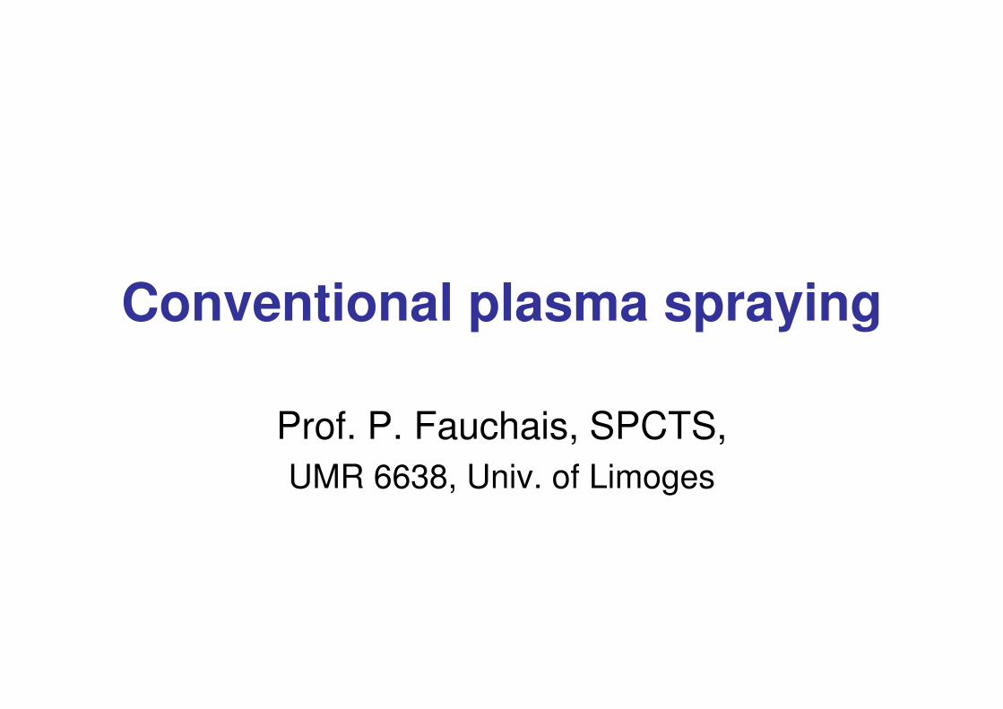
Combustion
Wi P d
Plasma
Ai Ch b
Electric
Wire-Arc
Ai Ch b
Classification of Thermal Spray Technologies
Wire Powder
Flame
D-Gun
HVOF
Air Chamber
Shroud
Vacuum
Inert
Underwater
Air Chamber
Shroud
Vacuum
Inert
APS
VPS
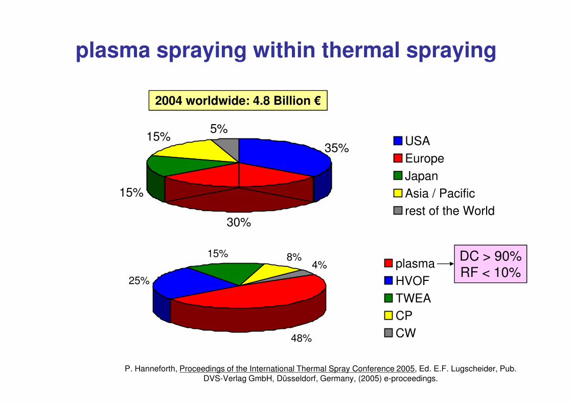
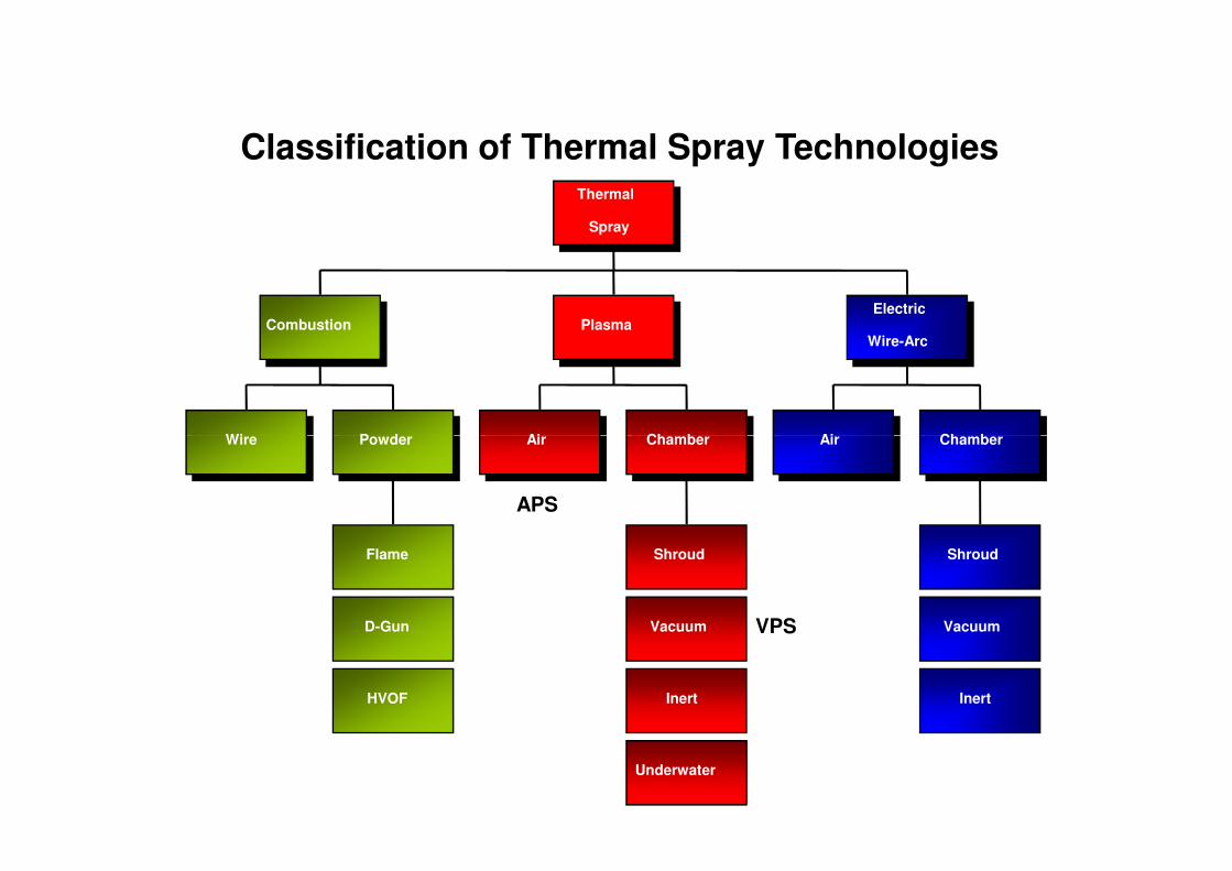
plasma spraying within thermal spraying
35%
5%
15%
15% USAEuropeJapanAsia / Pacific
2004 worldwide: 4.8 Billion €
30%rest of the World
48%
25%
15% 8%4% plasma
HVOFTWEACPCW
DC > 90%RF < 10%
P. Hanneforth, Proceedings of the International Thermal Spray Conference 2005, Ed. E.F. Lugscheider, Pub. DVS-Verlag GmbH, Düsseldorf, Germany, (2005) e-proceedings.
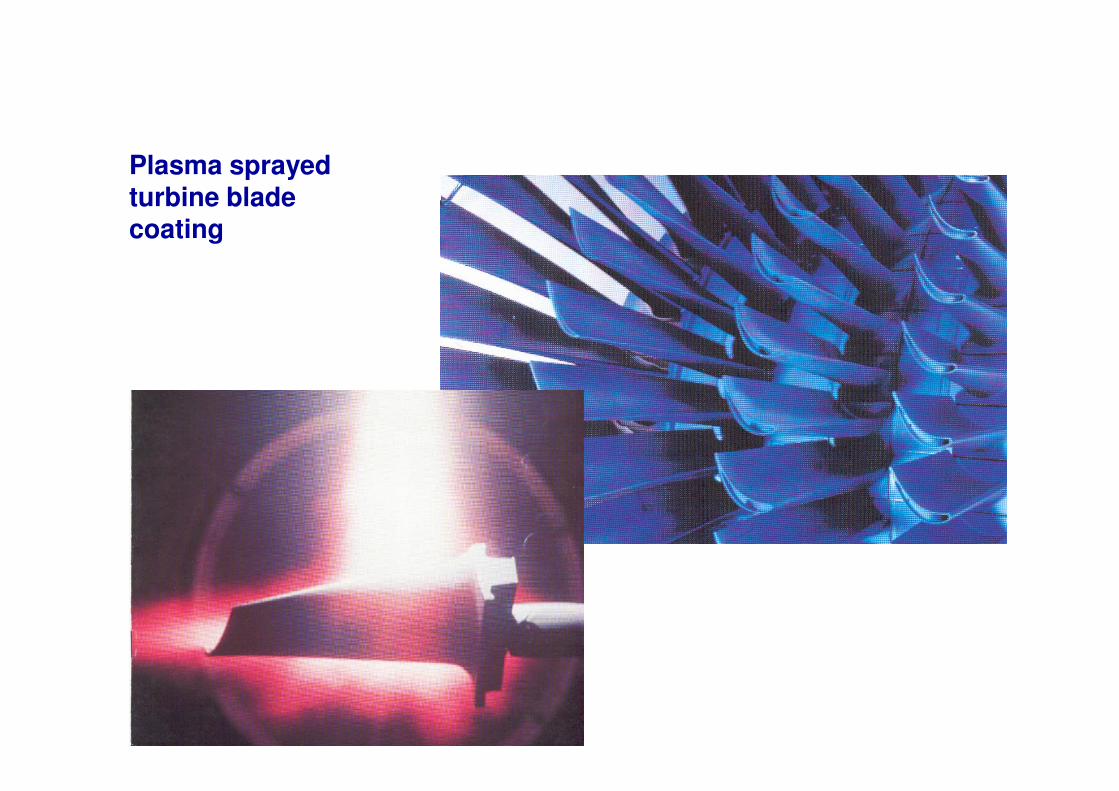
Plasma sprayed turbine blade coating
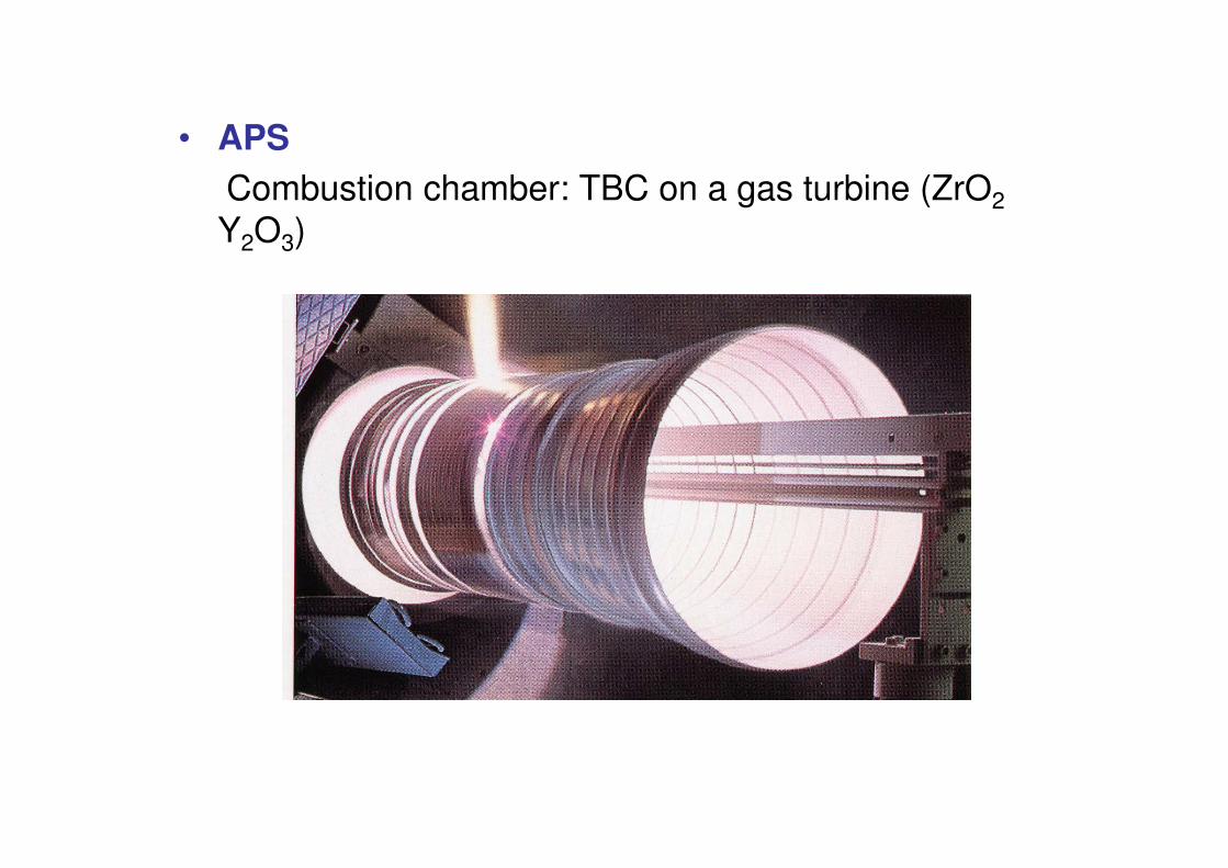
• APSCombustion chamber: TBC on a gas turbine (ZrO2Y2O3)
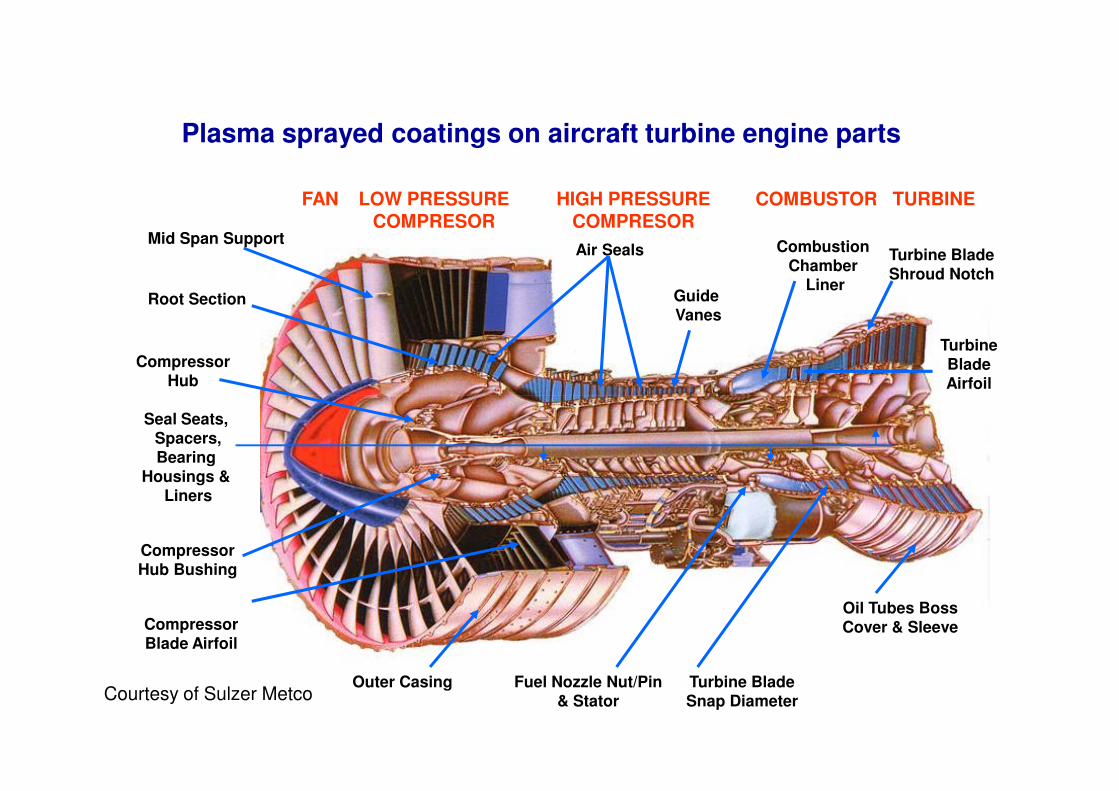
Plasma sprayed coatings on aircraft turbine engine parts
Mid Span Support
Root Section
CompressorHub
Air Seals
Guide Vanes
CombustionChamber
Liner
Turbine BladeShroud Notch
Turbine BladeAirfoil
FAN LOW PRESSURECOMPRESOR
HIGH PRESSURECOMPRESOR
COMBUSTOR TURBINE
CompressorHub Bushing
CompressorBlade Airfoil
Oil Tubes BossCover & Sleeve
Fuel Nozzle Nut/Pin& Stator
Seal Seats, Spacers,Bearing
Housings & Liners
Outer Casing Turbine BladeSnap DiameterCourtesy of Sulzer Metco
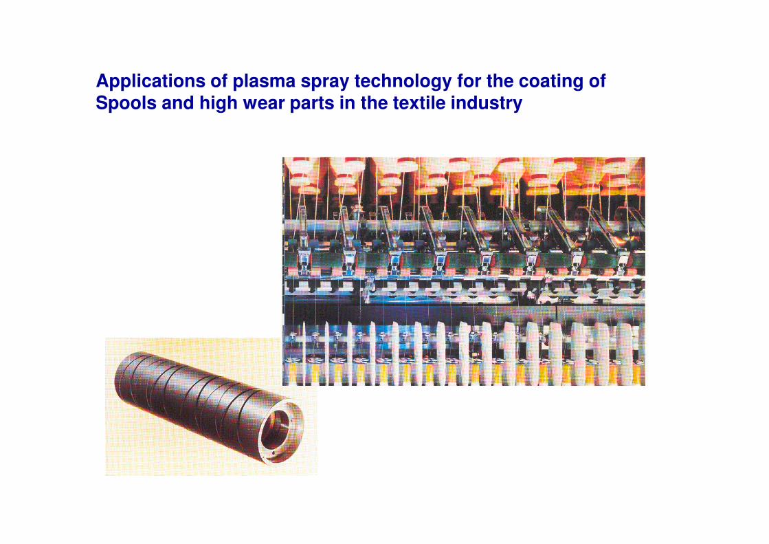
Applications of plasma spray technology for the coating of Spools and high wear parts in the textile industry
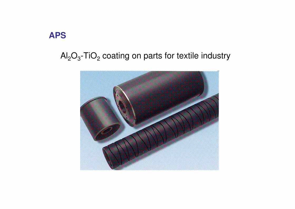
APS
Al2O3-TiO2 coating on parts for textile industry
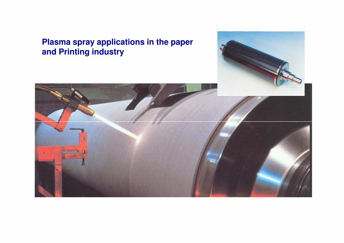
Plasma spray applications in the paper and Printing industry
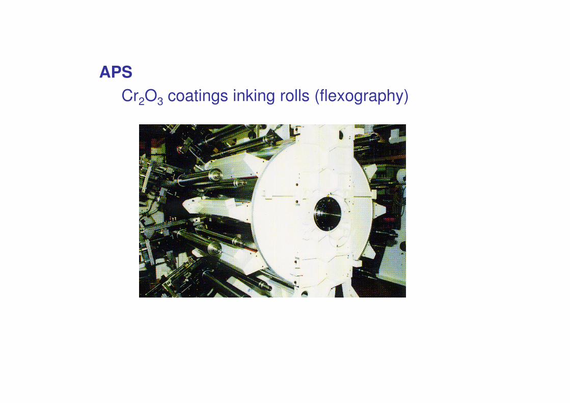
APSCr2O3 coatings inking rolls (flexography)
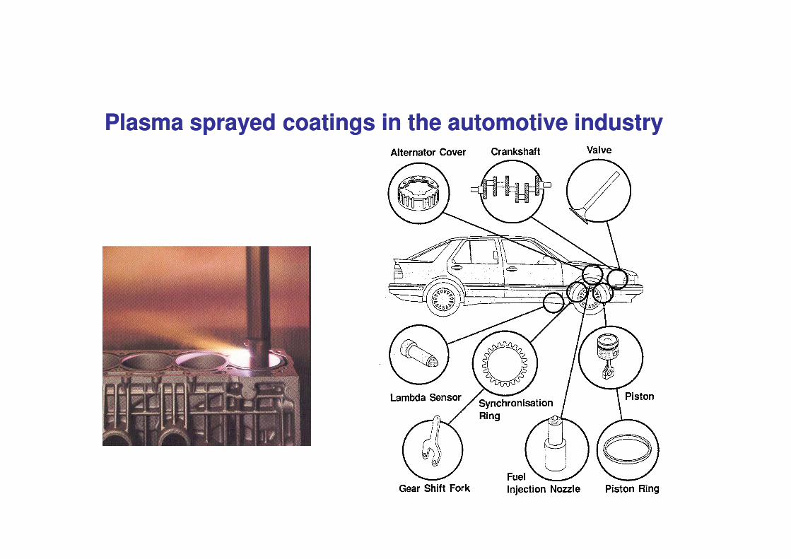
Plasma sprayed coatings in the automotive industryPlasma sprayed coatings in the automotive industry
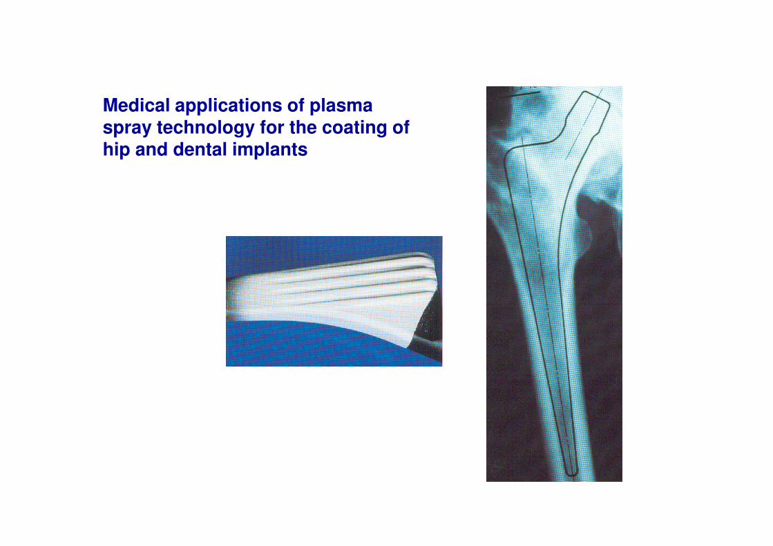
Medical applications of plasma spray technology for the coating of hip and dental implants
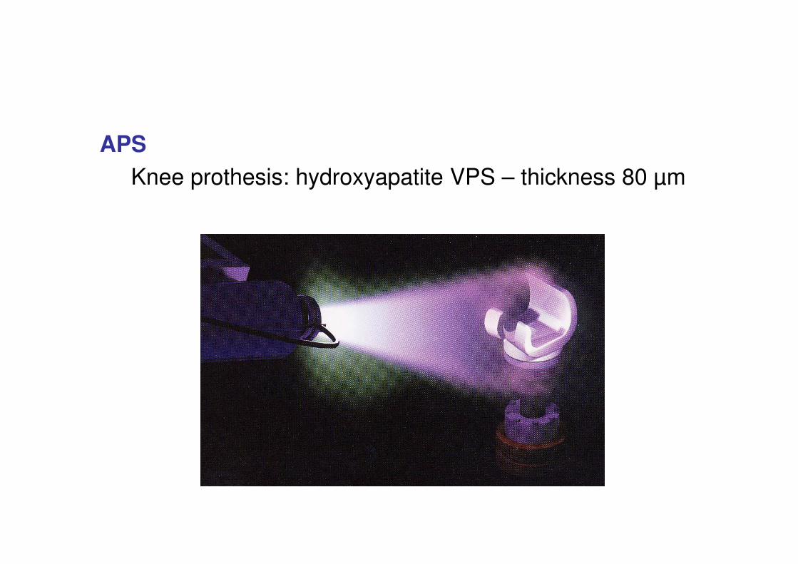
APSKnee prothesis: hydroxyapatite VPS – thickness 80 μm
Coating main functions :
1.Wear2.Corrosion – oxidation3.Thermal protection4.Strength (free standing spray, Formed
component)5.Other function
Plasma jets
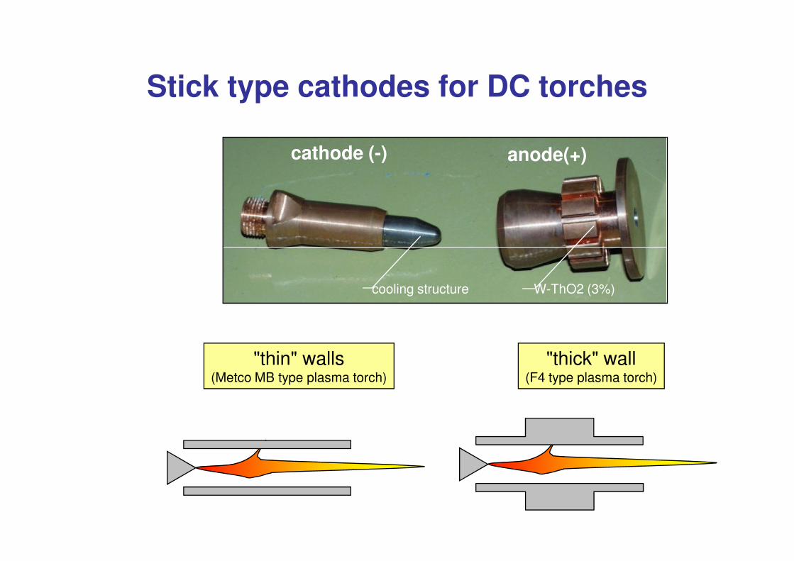
Stick type cathodes for DC torches
anode(+)cathode (-)
"thin" walls(Metco MB type plasma torch)
"thick" wall(F4 type plasma torch)
cooling structure W-ThO2 (3%)
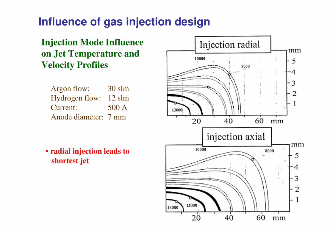
Injection Mode Influence on Jet Temperature andVelocity Profiles
Argon flow: 30 slmHydrogen flow: 12 slmCurrent: 500 AAnode diameter: 7 mm
Influence of gas injection design
• radial injection leads toshortest jet
Anode diameter: 7 mm
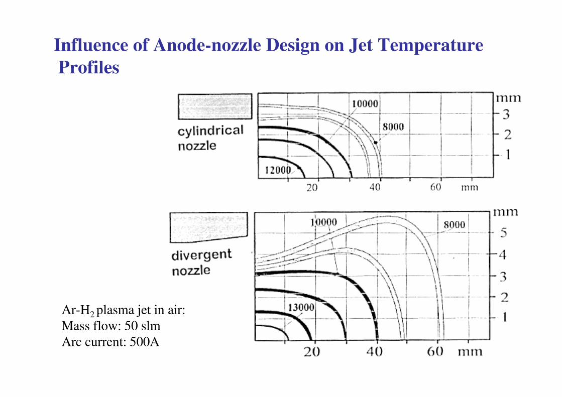
Influence of Anode-nozzle Design on Jet TemperatureProfiles
Ar-H2 plasma jet in air: Mass flow: 50 slmArc current: 500A
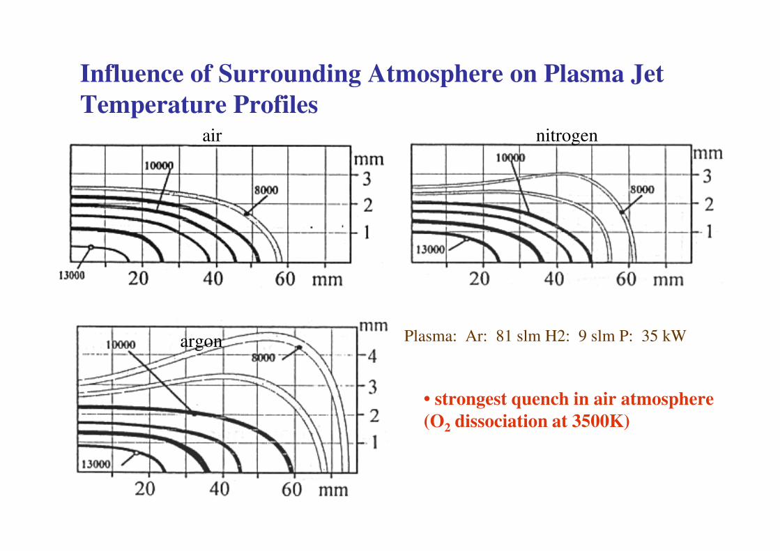
Influence of Surrounding Atmosphere on Plasma Jet Temperature Profiles
nitrogenair
Plasma: Ar: 81 slm H2: 9 slm P: 35 kWargon
• strongest quench in air atmosphere(O2 dissociation at 3500K)
Anode Attachment Instabilities
QuickTime™ et undécompresseur
Ar-H2: ΔV/Vm = 1→ΔP/Pm =1 from 20 to 40kW at about 5000Hz!
Ar He: ΔV/Vdécompresseur sont requis pour visionner cette image. Ar-He: ΔV/Vm =
O.41→ ΔP/Pm =0.4 from 19.6 to 30kW at about 5000Hz!
Arc modelling: 3D+time dependent
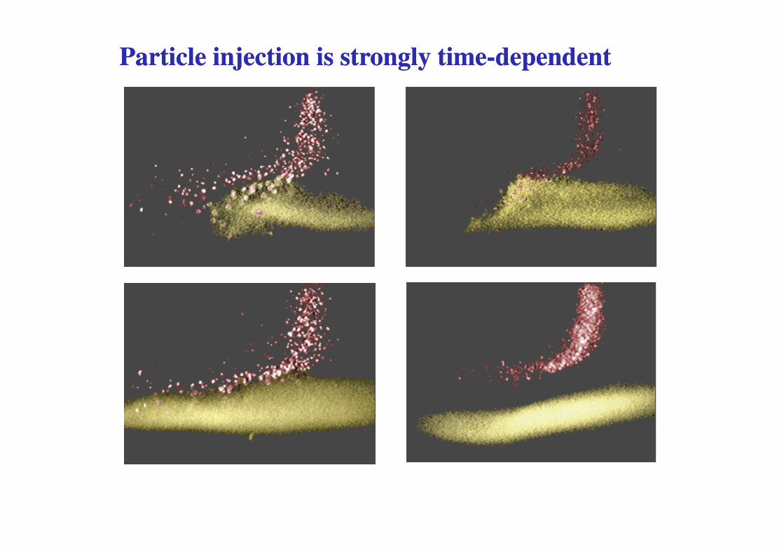
Particle injection is strongly timeParticle injection is strongly time--dependentdependent
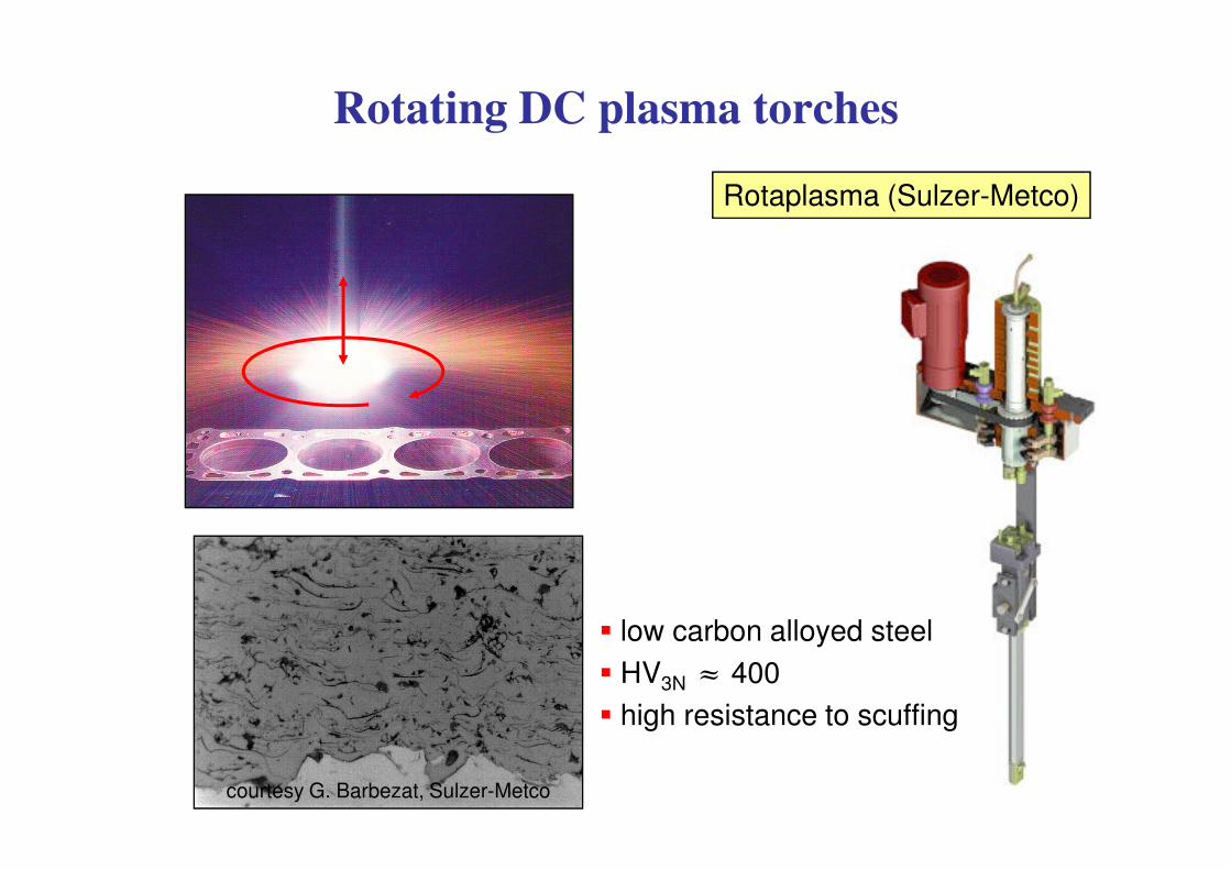
Rotating DC plasma torches
Rotaplasma (Sulzer-Metco)
� low carbon alloyed steel� HV3N � 400� high resistance to scuffing
courtesy G. Barbezat, Sulzer-Metco
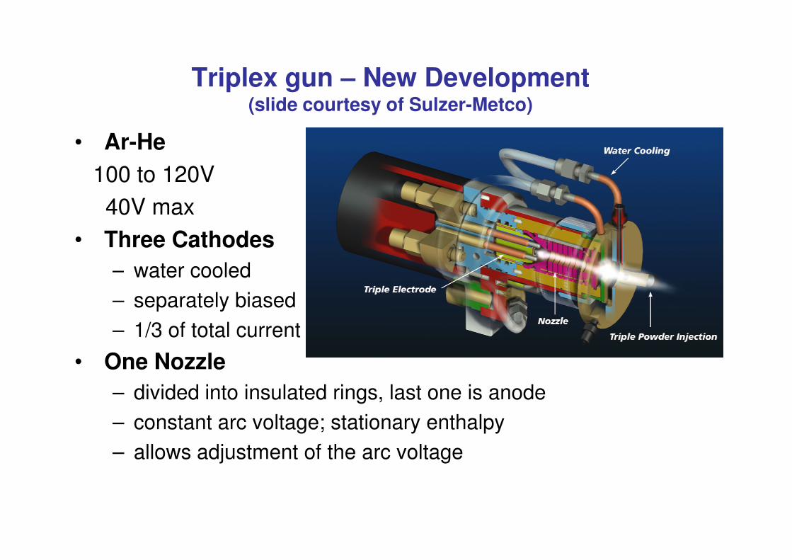
Triplex gun – New Development (slide courtesy of Sulzer-Metco)
• Ar-He100 to 120V40V max
• Three Cathodes– water cooled– separately biased– 1/3 of total current
• One Nozzle– divided into insulated rings, last one is anode– constant arc voltage; stationary enthalpy– allows adjustment of the arc voltage
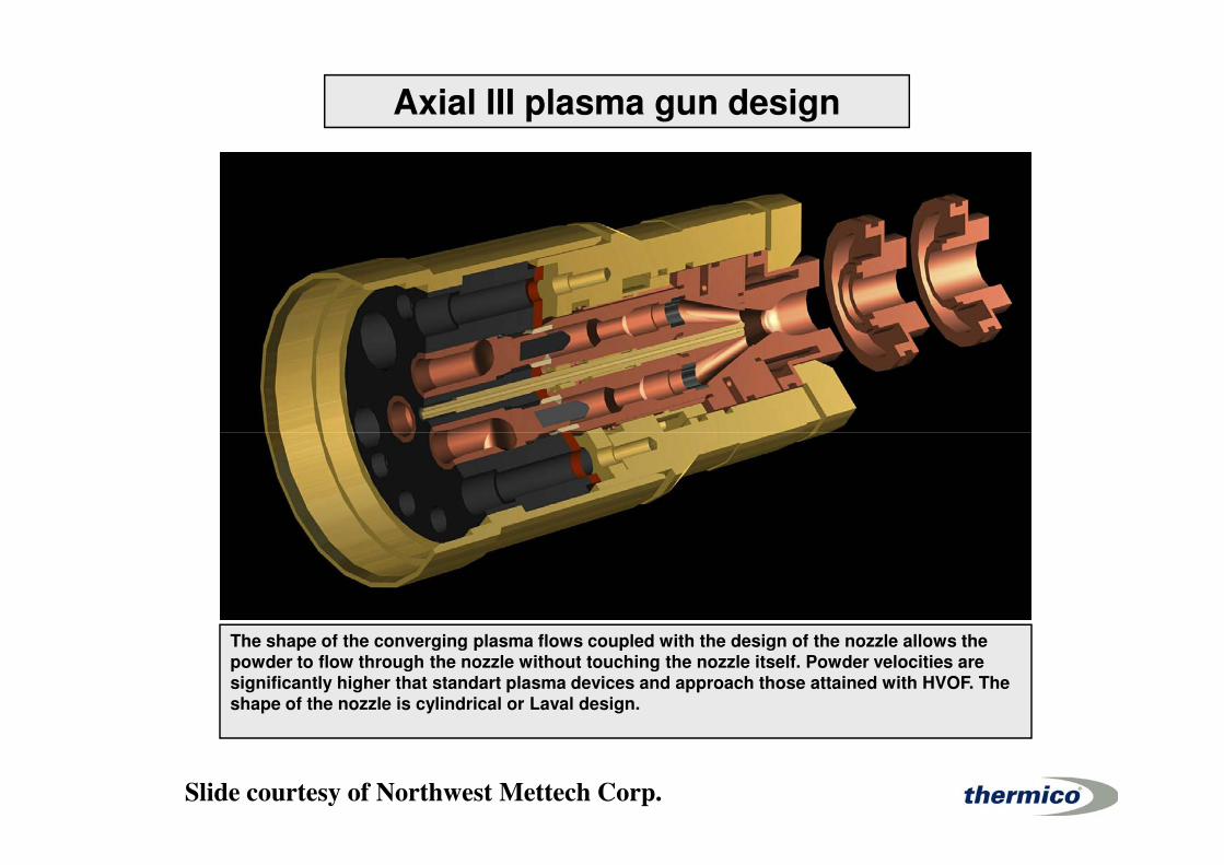
Axial III plasma gun design
The shape of the converging plasma flows coupled with the design of the nozzle allows the powder to flow through the nozzle without touching the nozzle itself. Powder velocities are significantly higher that standart plasma devices and approach those attained with HVOF. Theshape of the nozzle is cylindrical or Laval design.
Slide courtesy of Northwest Mettech Corp.
Plasma-particles transfers
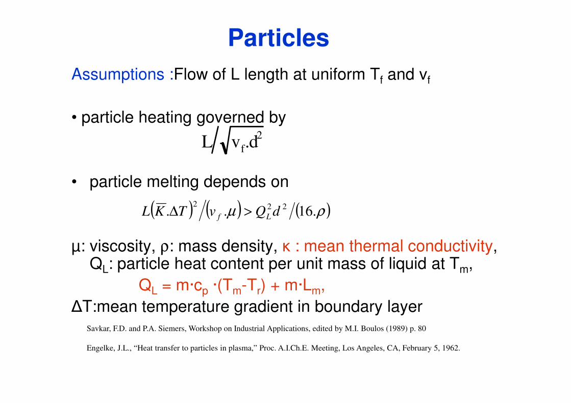
Assumptions :Flow of L length at uniform Tf and vf
• particle heating governed by
• particle melting depends on
L vf.d2
( ) ( )2
Particles
μ: viscosity, ρ: mass density, � : mean thermal conductivity, QL: particle heat content per unit mass of liquid at Tm,
QL = m·cp ·(Tm-Tr) + m·Lm, �T:mean temperature gradient in boundary layer
Savkar, F.D. and P.A. Siemers, Workshop on Industrial Applications, edited by M.I. Boulos (1989) p. 80
Engelke, J.L., “Heat transfer to particles in plasma,” Proc. A.I.Ch.E. Meeting, Los Angeles, CA, February 5, 1962.
( ) ( ) ( )ρμ .16.. 222dQvTKL Lf >Δ
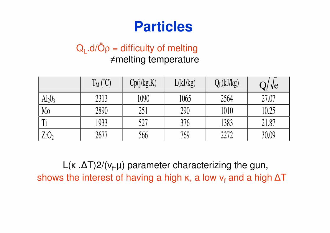
QL.d/Öρ = difficulty of melting�melting temperature
TM (˚C) Cp(j/kg.K) L(kJ/kg) QL(kJ/kg) QL e
Al203 2313 1090 1065 2564 27.07 Mo 2890 251 290 1010 10.25
Particles
Ti 1933 527 376 1383 21.87 ZrO2 2677 566 769 2272 30.09
L(� .�T)2/(vf.μ) parameter characterizing the gun,shows the interest of having a high �, a low vf and a high �T
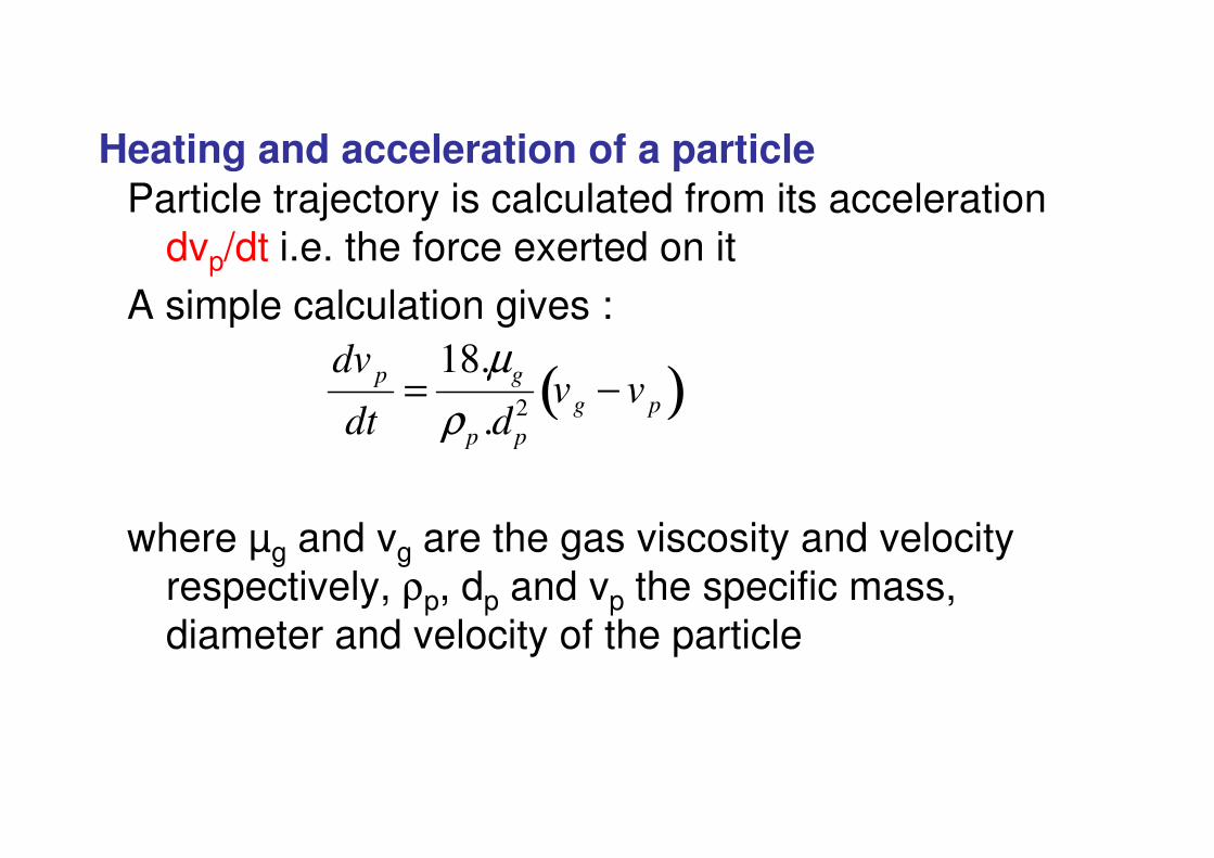
Particle trajectory is calculated from its acceleration dvp/dt i.e. the force exerted on it
A simple calculation gives :
Heating and acceleration of a particle
dvp
dt=
18.μg
ρ d2 vg − vp( )
where μg and vg are the gas viscosity and velocity respectively, ρp, dp and vp the specific mass, diameter and velocity of the particle
dt ρp .dp
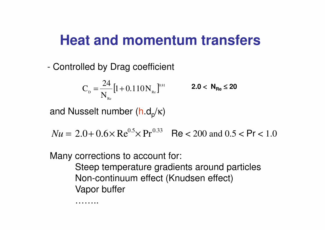
Heat and momentum transfers
- Controlled by Drag coefficient
and Nusselt number (h.dp/κ)
[ ] 81.0
Re
Re
DN110.01
N
24C += 2.0 <<<< NRe ≤≤≤≤ 20
( p )
Re < 200 and 0.5 < Pr < 1.0
Many corrections to account for:Steep temperature gradients around particlesNon-continuum effect (Knudsen effect)Vapor buffer……..
Nu = 2.0+ 0.6× Re0.5× Pr0.33
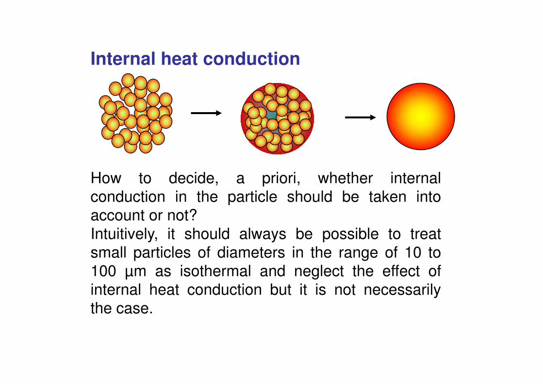
Internal heat conduction
How to decide, a priori, whether internald ti i th ti l h ld b t k i tconduction in the particle should be taken into
account or not?Intuitively, it should always be possible to treatsmall particles of diameters in the range of 10 to100 μm as isothermal and neglect the effect ofinternal heat conduction but it is not necessarilythe case.
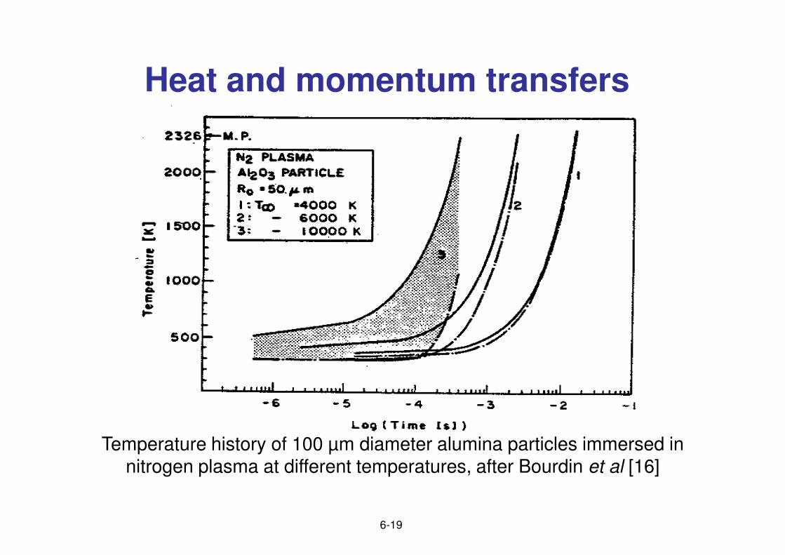
Heat and momentum transfers
Temperature history of 100 μm diameter alumina particles immersed in nitrogen plasma at different temperatures, after Bourdin et al [16]
6-19
Heat and momentum transfers
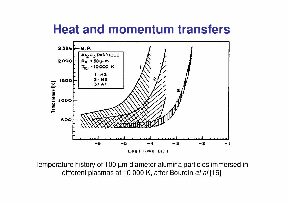
Temperature history of 100 μm diameter alumina particles immersed in different plasmas at 10 000 K, after Bourdin et al [16]
Heat and momentum transfers
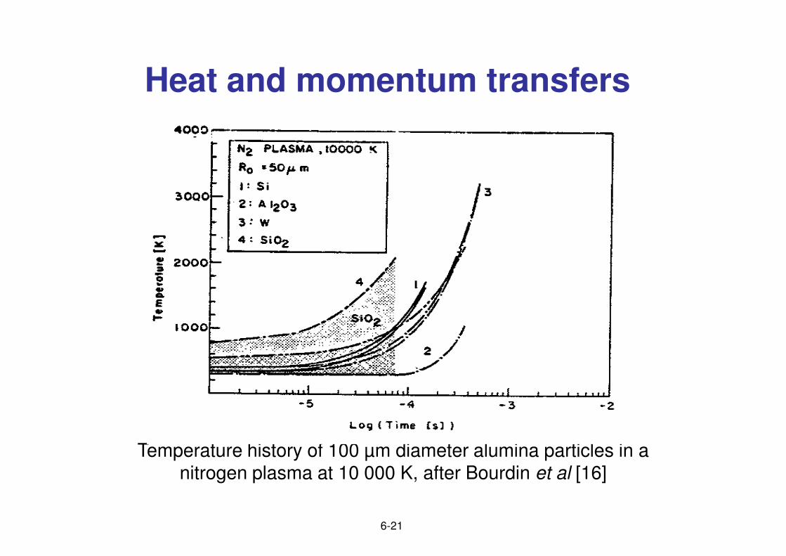
Temperature history of 100 μm diameter alumina particles in a nitrogen plasma at 10 000 K, after Bourdin et al [16]
6-21
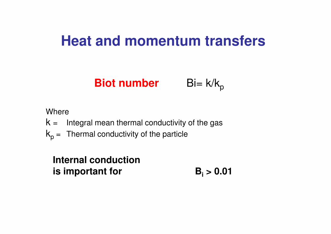
Biot number Bi= k/kp
Where
Heat and momentum transfers
k = Integral mean thermal conductivity of the gaskp = Thermal conductivity of the particle
Internal conductionis important for Bi > 0.01
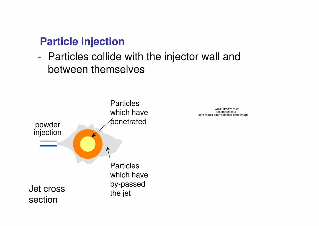
- Particles collide with the injector wall and between themselves
Particle injection
QuickTime™ et undécompresseur
Particles which have p
sont requis pour visionner cette image.
Particles which have by-passed the jet
which have penetratedpowder
injection
Jet cross section
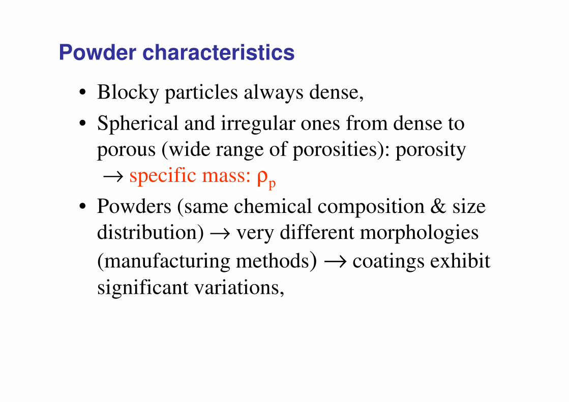
• Blocky particles always dense,
• Spherical and irregular ones from dense to porous (wide range of porosities): porosity → specific mass: ρp
P d ( h i l iti & i
Powder characteristics
• Powders (same chemical composition & size distribution) → very different morphologies (manufacturing methods) → coatings exhibit significant variations,
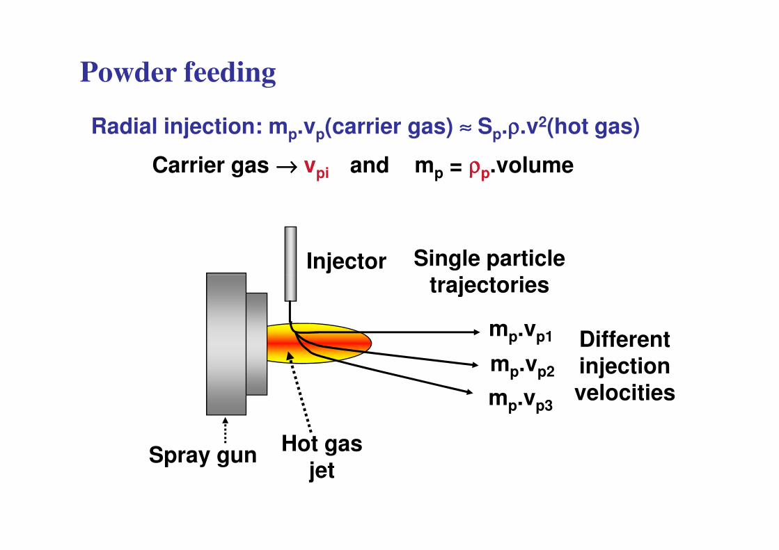
Powder feeding
Radial injection: mp.vp(carrier gas) ≈≈≈≈ Sp.ρρρρ.v2(hot gas)
Injector Single particle
Carrier gas →→→→ vpi and mp = ρρρρp.volume
mp.vp1
mp.vp2
mp.vp3
Hot gasjet
Spray gun
trajectories
Differentinjectionvelocities
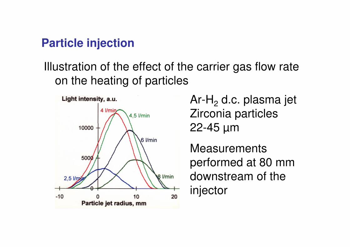
Illustration of the effect of the carrier gas flow rate on the heating of particles
Ar-H2 d.c. plasma jet Zirconia particles 22 45
Particle injection
22-45 μm
Measurements performed at 80 mm downstream of the injector
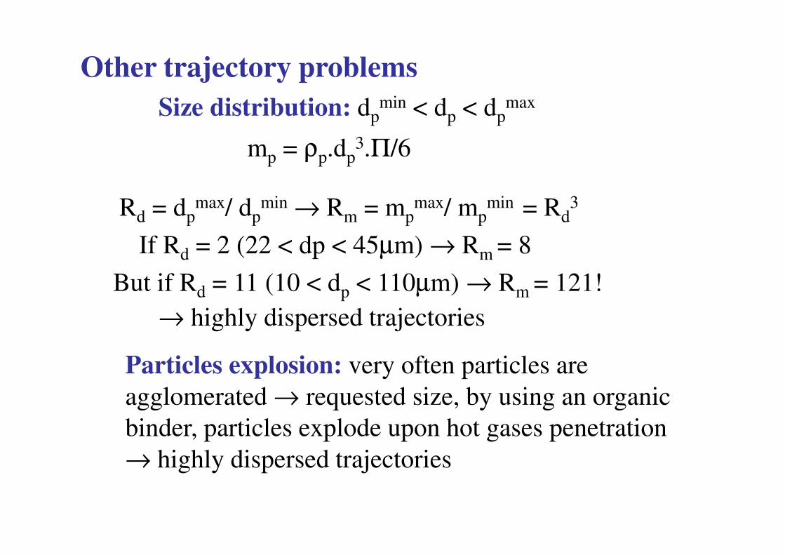
Other trajectory problemsSize distribution: dp
min < dp < dpmax
mp = ρp.dp3.Π/6
Rd = dpmax/ dp
min → Rm = mpmax/ mp
min = Rd3
If Rd = 2 (22 < dp < 45μm) → Rm = 8
B t if R 11 (10 < d < 110 ) → R 121!But if Rd = 11 (10 < dp < 110μm) → Rm = 121!→ highly dispersed trajectories
Particles explosion: very often particles are agglomerated → requested size, by using an organic binder, particles explode upon hot gases penetration → highly dispersed trajectories
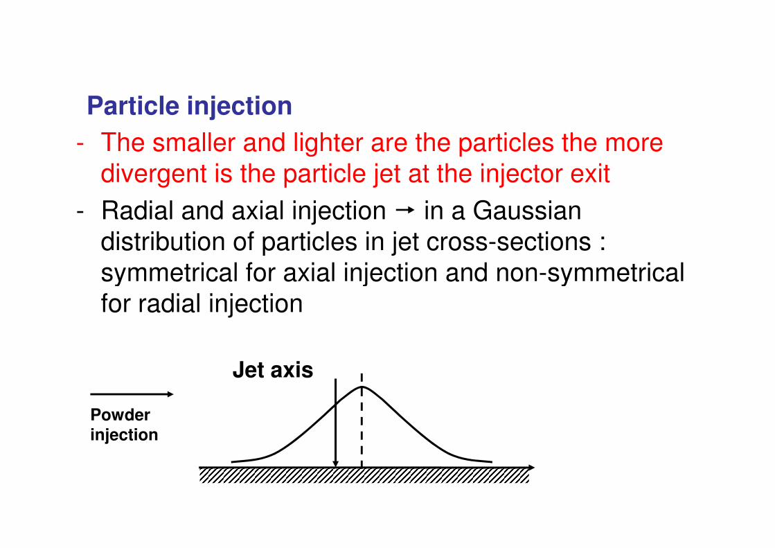
- The smaller and lighter are the particles the more divergent is the particle jet at the injector exit
- Radial and axial injection � in a Gaussian distribution of particles in jet cross-sections : symmetrical for axial injection and non-symmetrical
Particle injection
symmetrical for axial injection and non-symmetrical for radial injection
Jet axis
Powderinjection
In-flight reactions (oxidation) with hot gases
• Reaction controlled by diffusion: rather slow process
Particles in-flight in hot gases react with them, especiallywhen spraying in air (with its entrainment). Two types of reaction occurs:
QuickTime™ et undécompresseur
sont requis pour visionner cette image.
QuickTime™ et undécompresseur
sont requis pour visionner cette image.
Iron particle in Ar-H2 DC plasma jet
30μm 80μm
• Reaction controlled by convection, occurs if:νg/νp > 50 & Rep > 20
In-flight reactions (oxidation) with hot gases
QuickTime™ et undécompresseur
sont requis pour visionner cette image.
QuickTime™ et undécompresseur
sont requis pour visionner cette image.
Oxidation by diffusion 3wt%, by convection 13wt%!
Hillvortex
- Controlled atmosphere spraying offers the possibility of improving coating quality and bond strength
- Advantages:* l i f b h b d
CONTROL OF THE ATMOSPHERE
* temperature regulation of both substrate and coating (up to 1000�C if the treated material can sustain it) �better adhesion (diffusion promoted �better densification) * absence of oxides* improvement in hardness, thickness capability and deposition efficiency (fatter and longer jets when no air is present, especially for plasma jets)
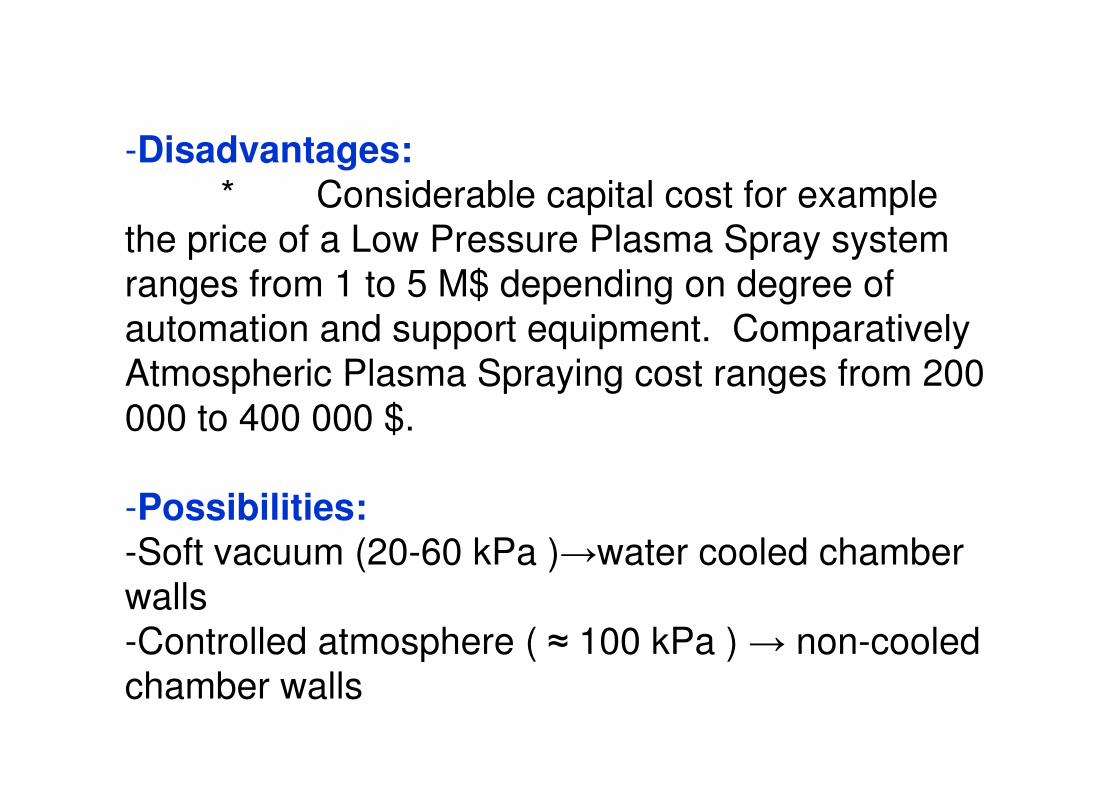
-Disadvantages:* Considerable capital cost for example
the price of a Low Pressure Plasma Spray system ranges from 1 to 5 M$ depending on degree of automation and support equipment. Comparatively Atmospheric Plasma Spraying cost ranges from 200 000 to 400 000 $.
-Possibilities:-Soft vacuum (20-60 kPa )�water cooled chamber walls-Controlled atmosphere ( � 100 kPa ) � non-cooled chamber walls
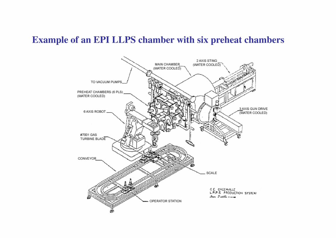
Example of an EPI LLPS chamber with six preheat chambers
Particles flattening and solidification
����������� �
�
�������������������
�
�� ���
��������������
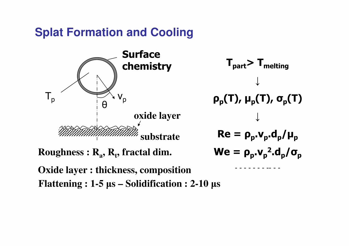
oxide layer
Splat Formation and Cooling
���������� �!��"��������#� �!��
$ $ $ $ $ $ $ $$ $ $
substrate
Roughness : Ra, Rt, fractal dim.
Oxide layer : thickness, compositionFlattening : 1-5 �s – Solidification : 2-10 �s
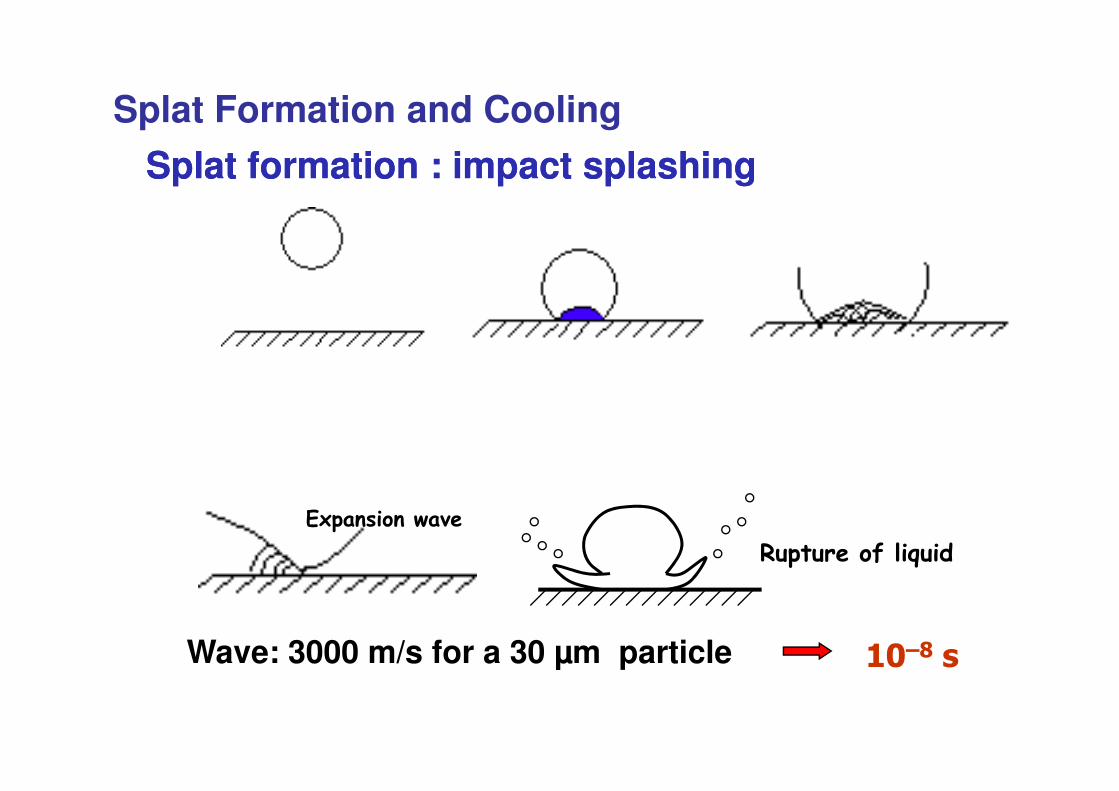
Splat formation : impact splashingSplat formation : impact splashing
Splat Formation and Cooling
����������� ������ �������
Wave: 3000 m/s for a 30 μm particle %&'( �
)�*���������������������*
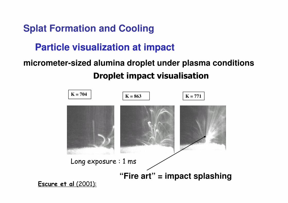
K = 863K = 704 K = 771
Particle visualization at impactParticle visualization at impact
micrometer-sized alumina droplet under plasma conditions
Splat Formation and Cooling
����� ��� �������
���������������
“Fire art” = impact splashing
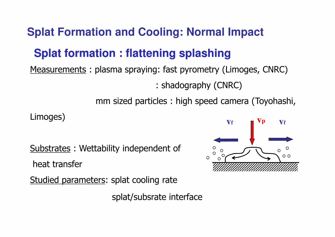
Splat formation : flattening splashingSplat formation : flattening splashing+��������� ,�� �����������,��������������-�������./�.�
,�������������./�.�
���0�������� ���,�����������������������������
-������ v
Splat Formation and Cooling: Normal Impact
-������
��1������ ,������1� ������������������
�����������
���������������,��� ������ �������
�� �����1�������������
vp vfvf
Tsub : R T
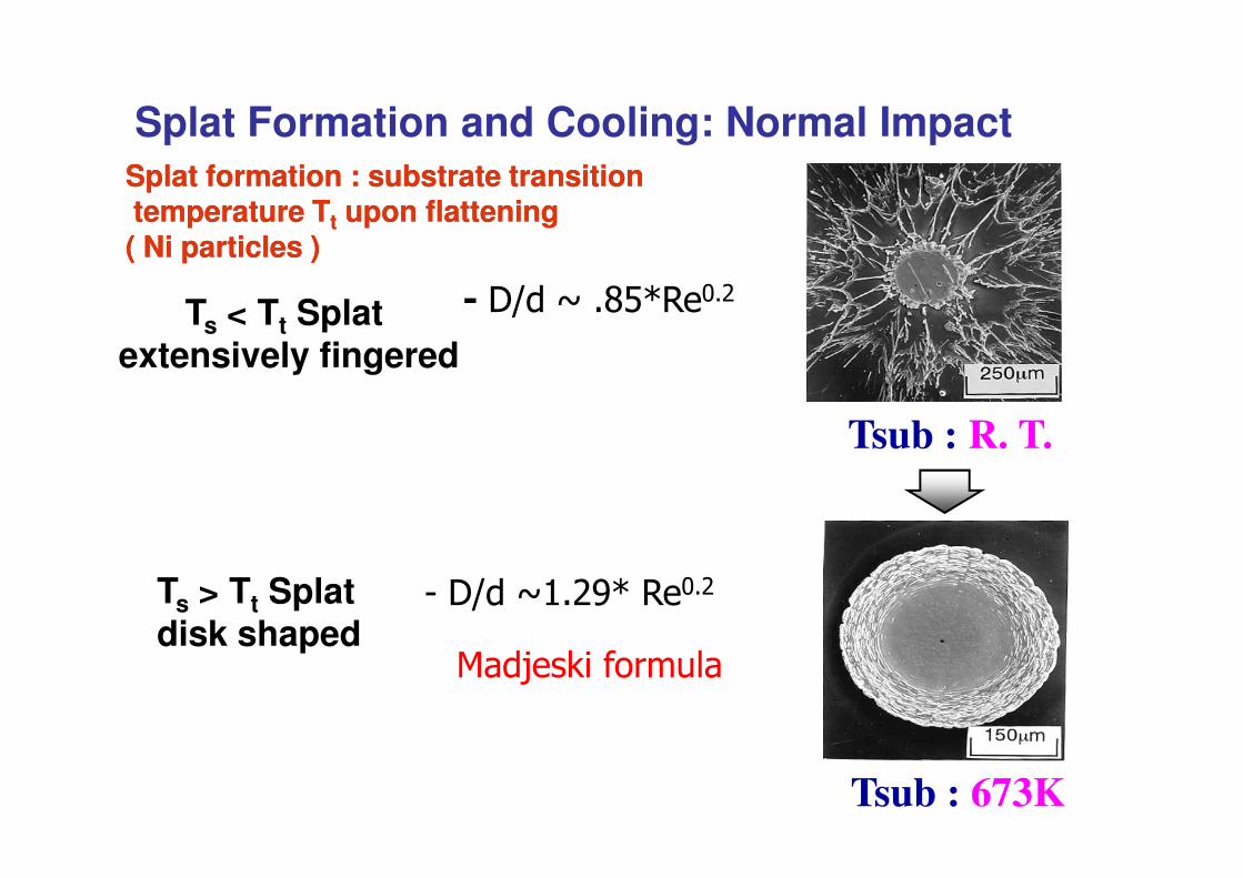
� ����2�� 34��!�"
Splat formation : substrate transitionSplat formation : substrate transitiontemperature Ttemperature Ttt upon flattening upon flattening ( Ni particles )( Ni particles )
Ts < Tt Splat extensively fingered
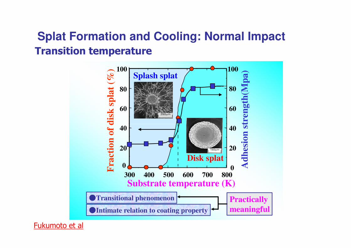
Splat Formation and Cooling: Normal Impact
Tsub : R. T.
Tsub : 673K
$ ����2#�"54���!�"
+��6��7����� �
Ts > Tt Splat disk shaped
60
80
100Splash splat
disk
spl
at (
%)
tren
gth(
Mpa
)
60
80
100
��� ����* ��������Splat Formation and Cooling: Normal Impact
0
20
40
300 400 500 600 700 800Substrate temperature (K)
Disk splat
Fra
ctio
n of
d
����Transitional phenomenon Practicallymeaningful
Adh
esio
n st
����Intimate relation to coating property
0
20
40
8�7���������
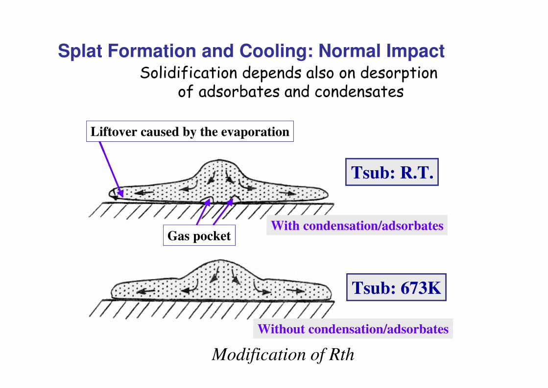
Liftover caused by the evaporation
Tsub: R.T.
Liftover caused by the evaporation
Tsub: R.T.
Liftover caused by the evaporation
Tsub: R.T.
���� ����������������������������� ����!������������������
Splat Formation and Cooling: Normal Impact
With condensation/adsorbatesGas pocket
Without condensation/adsorbates
Tsub: 673K
With condensation/adsorbatesGas pocket
With condensation/adsorbatesGas pocket
Without condensation/adsorbates
Tsub: 673K
Without condensation/adsorbates
Tsub: 673K
Modification of Rth
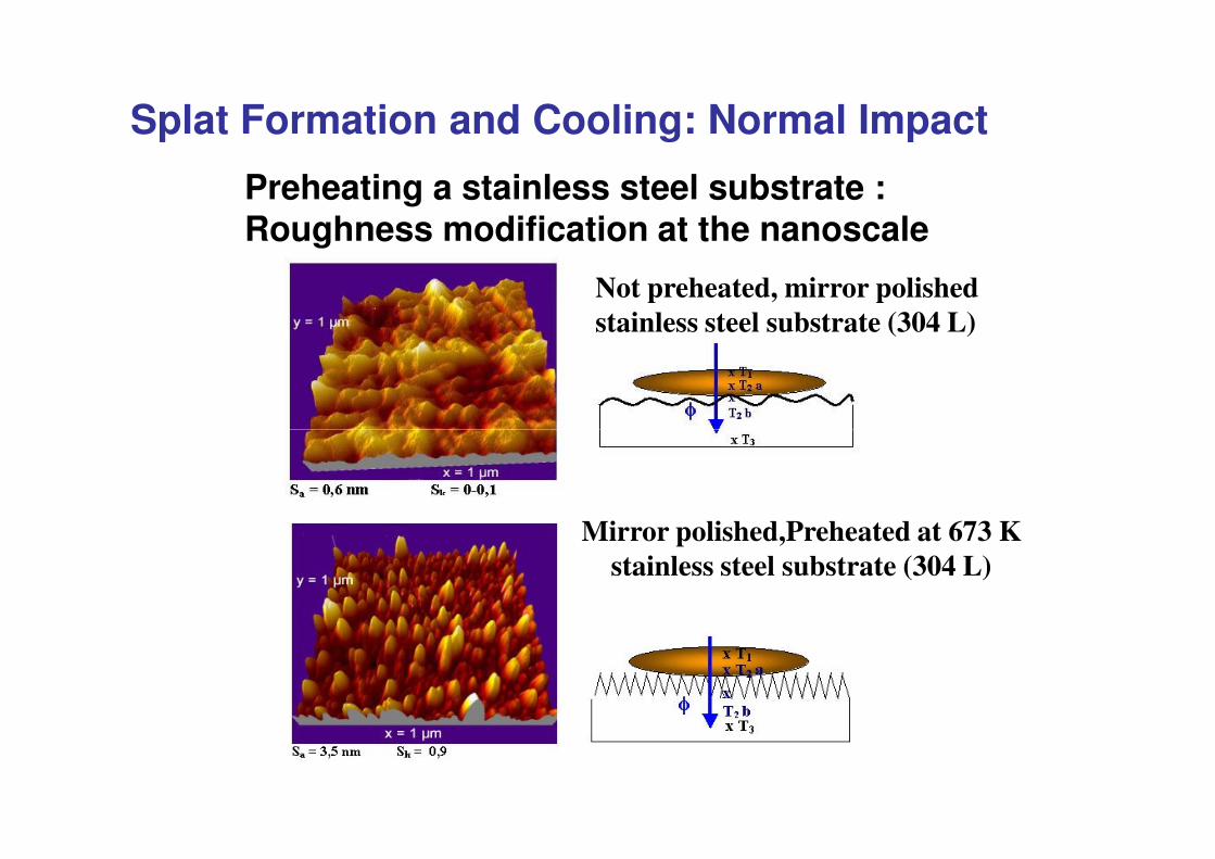
Preheating a stainless steel substrate : Roughness modification at the nanoscale
Not preheated, mirror polishedstainless steel substrate (304 L)
Splat Formation and Cooling: Normal Impact
Mirror polished,Preheated at 673 K stainless steel substrate (304 L)
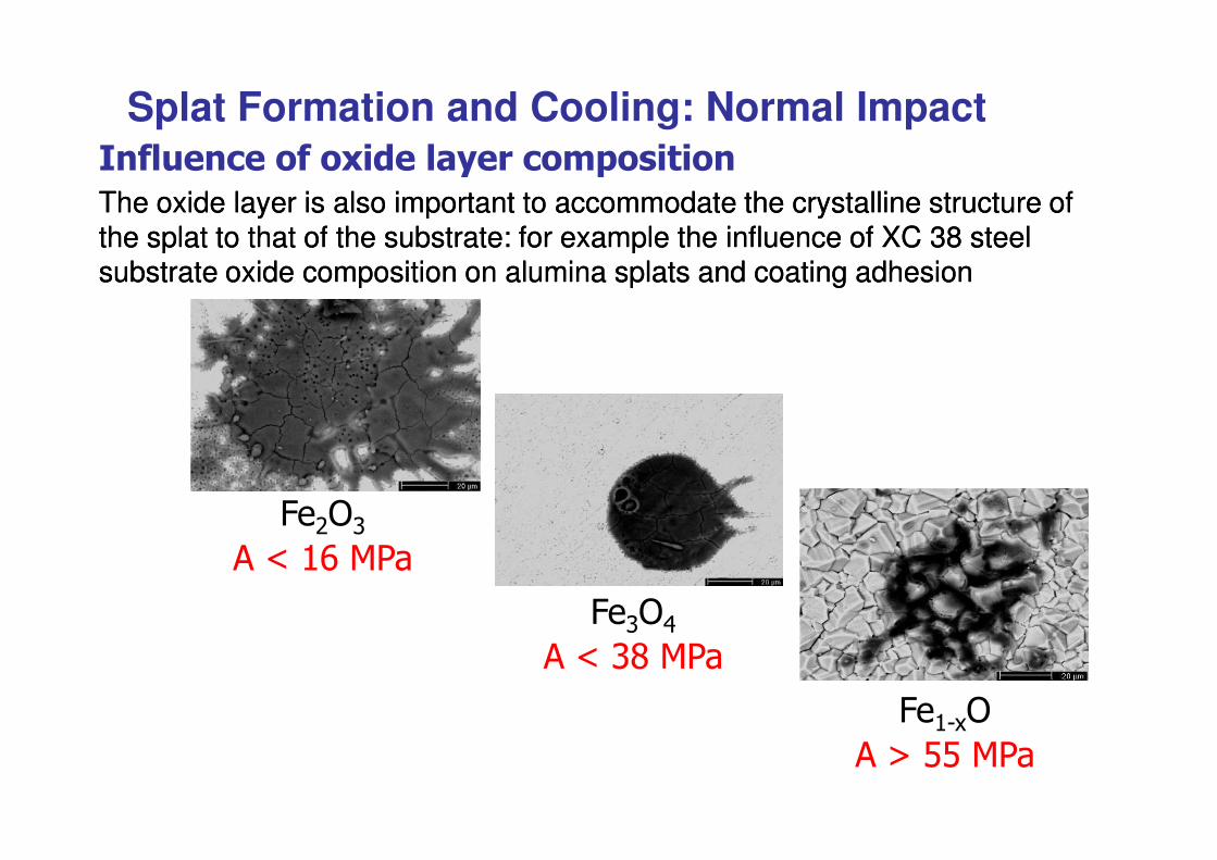
The oxide layer is also important to accommodate the crystalline structure of The oxide layer is also important to accommodate the crystalline structure of the splat to that of the substrate: for example the influence of XC 38 steel the splat to that of the substrate: for example the influence of XC 38 steel substrate oxide composition on alumina splats and coating adhesionsubstrate oxide composition on alumina splats and coating adhesion
9 ��� ��*��*:� �������*�*����* Splat Formation and Cooling: Normal Impact
8�";<�=�>�#?�+@�
8�<;A�=�>�< �+@�
8�#$$;=�%�33�+@�
40
50
60
70
B:����*��*:� ���*
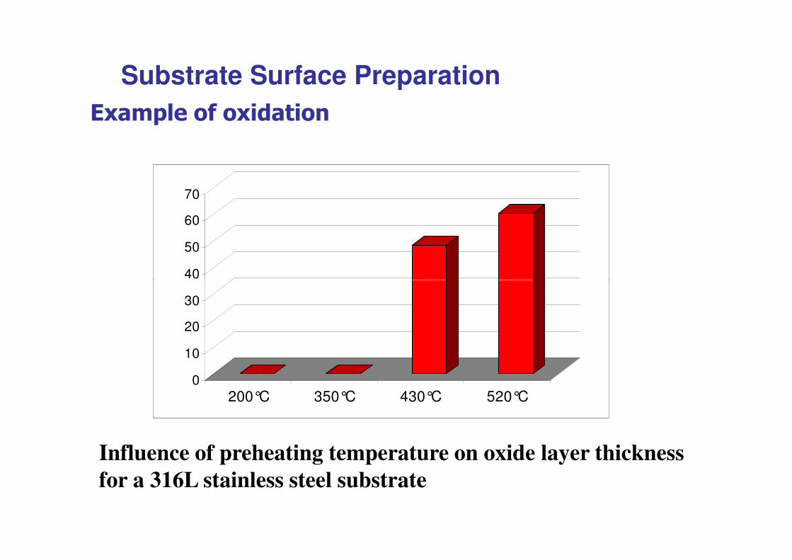
Substrate Surface Preparation
0
10
20
30
200°C 350°C 430°C 520°C
Influence of preheating temperature on oxide layer thickness for a 316L stainless steel substrate
Coating formation
Substrate Surface Preparation
• &�� � ��������'����� ���C�����*��� � ���C����#&&�–(&&�)*��C����+���
• B��� ���* �*���������� �� ������'����� ��• , ������* �*�������-���.�������*������������.� * * � � � * �
� �*��� �����**���� ���* �'����� ������ ���*�-� ���B� ������/�&�#�D������**�������*�� �0���� ���* ������������������ ��* �
�����1�σσσσ�!�ρρρρ����#�,���� ������*���� ����∼∼∼∼ ��
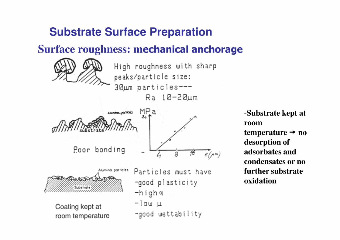
Surface roughness: m��� ������ ��*���
-Substrate kept at
Substrate Surface Preparation
room temperature ���� no desorption of adsorbates and condensates or no further substrate oxidation
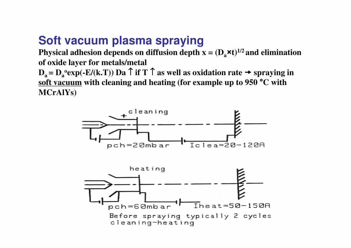
Soft vacuum plasma sprayingPhysical adhesion depends on diffusion depth x = (Da����t)1/2 and elimination of oxide layer for metals/metal Da = Da
oexp(-E/(k.T)) Da ↑↑↑↑ if T ↑↑↑↑ as well as oxidation rate ���� spraying in soft vacuum with cleaning and heating (for example up to 950 ����C with MCrAlYs)
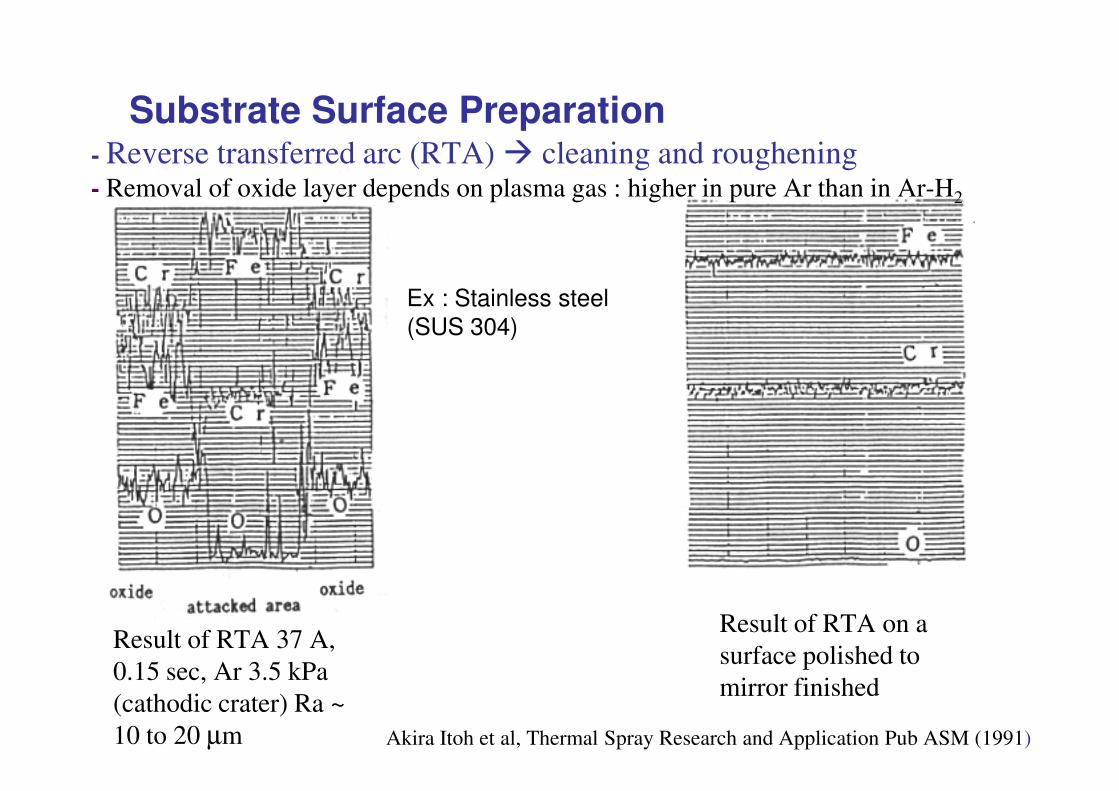
- Reverse transferred arc (RTA) � cleaning and roughening- Removal of oxide layer depends on plasma gas : higher in pure Ar than in Ar-H2
Substrate Surface Preparation
Ex : Stainless steel (SUS 304)
Result of RTA 37 A, 0.15 sec, Ar 3.5 kPa (cathodic crater) Ra ~ 10 to 20 μm
Result of RTA on a surface polished to mirror finished
Akira Itoh et al, Thermal Spray Research and Application Pub ASM (1991)
.���������������,������������������.���������������,������������������
8 ��������>�3�� !� >�� �����������>�#!�� "������������������
#!$#!! �
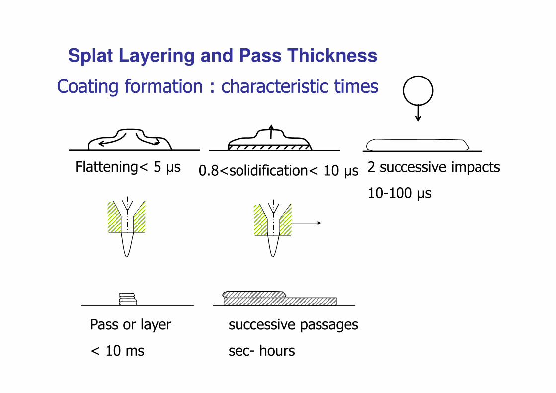
Splat Layering and Pass Thickness
#! #!!��
@������ ���
>�#!��
�������������������
���$ ����
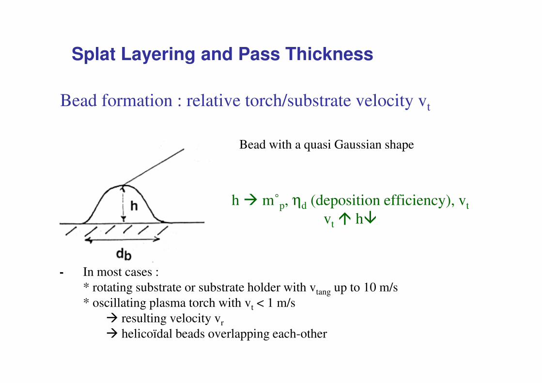
Bead formation : relative torch/substrate velocity vt
Bead with a quasi Gaussian shape
Splat Layering and Pass Thickness
h � m˚p, ηd (deposition efficiency), vt
vt � h�
- In most cases :* rotating substrate or substrate holder with vtang up to 10 m/s* oscillating plasma torch with vt < 1 m/s
� resulting velocity vr
� helicoïdal beads overlapping each-other
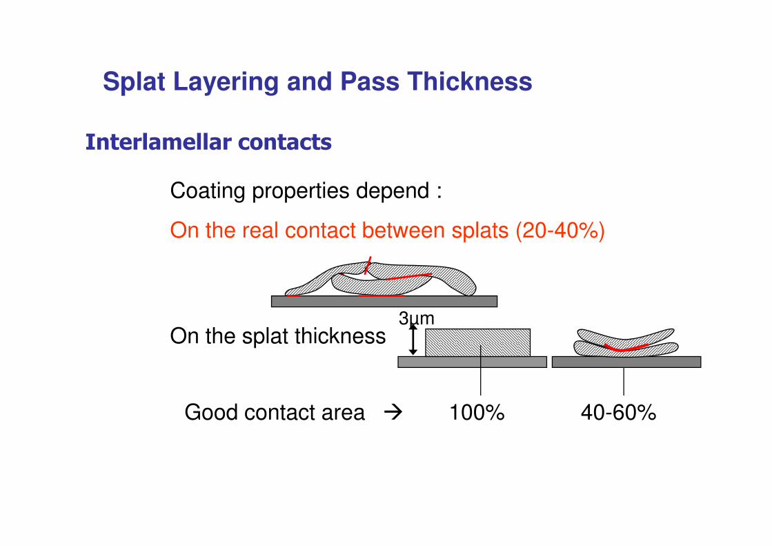
Coating properties depend :
On the real contact between splats (20-40%)
9 ����������* �����
Splat Layering and Pass Thickness
On the splat thickness
Good contact area � 100% 40-60%
3μm
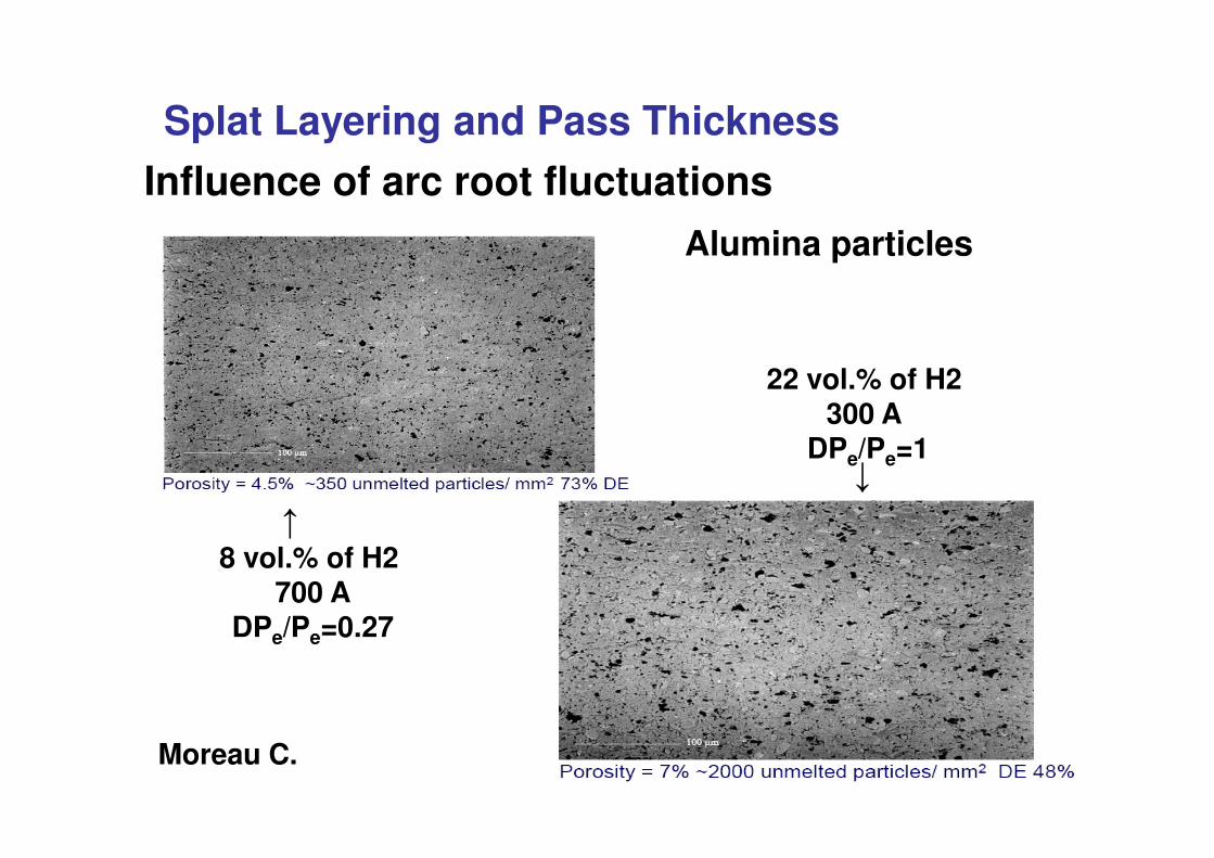
22 vol.% of H2300 A
Alumina particles
Splat Layering and Pass Thickness
Influence of arc root fluctuations
Moreau C.
8 vol.% of H2 700 A
DPe/Pe=0.27
DPe/Pe=1
�
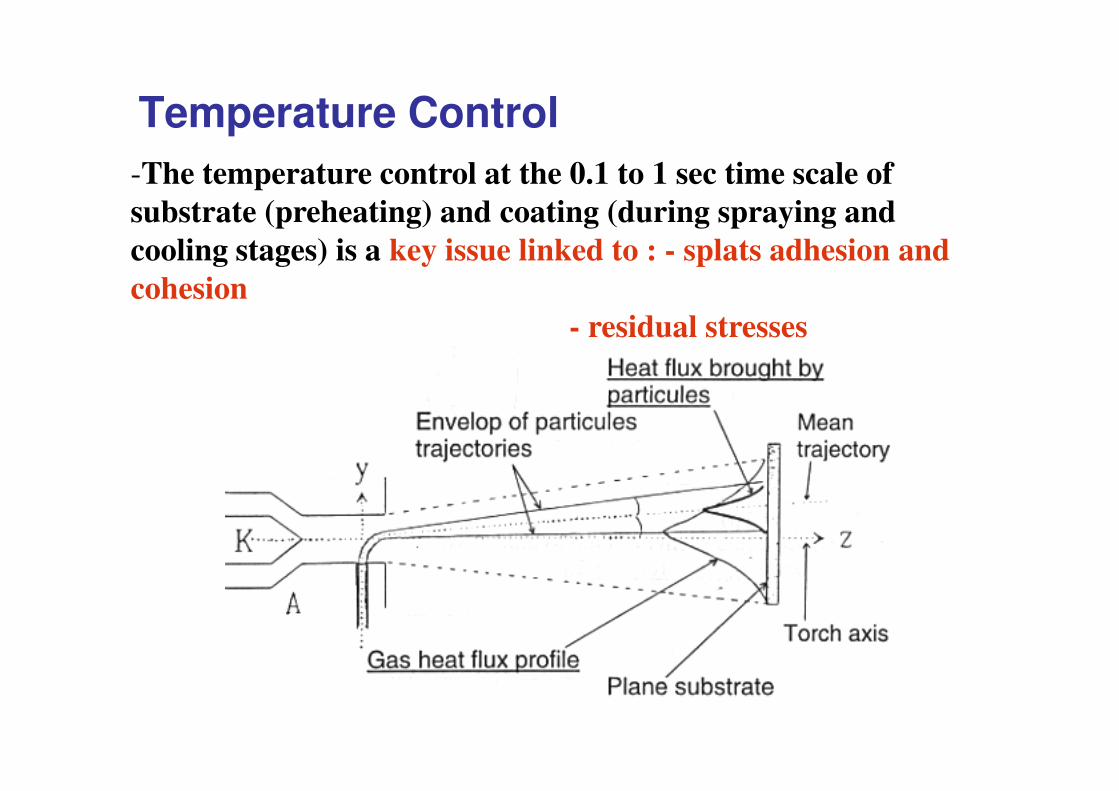
Temperature Control-The temperature control at the 0.1 to 1 sec time scale of substrate (preheating) and coating (during spraying and cooling stages) is a key issue linked to : - splats adhesion and cohesion
- residual stresses
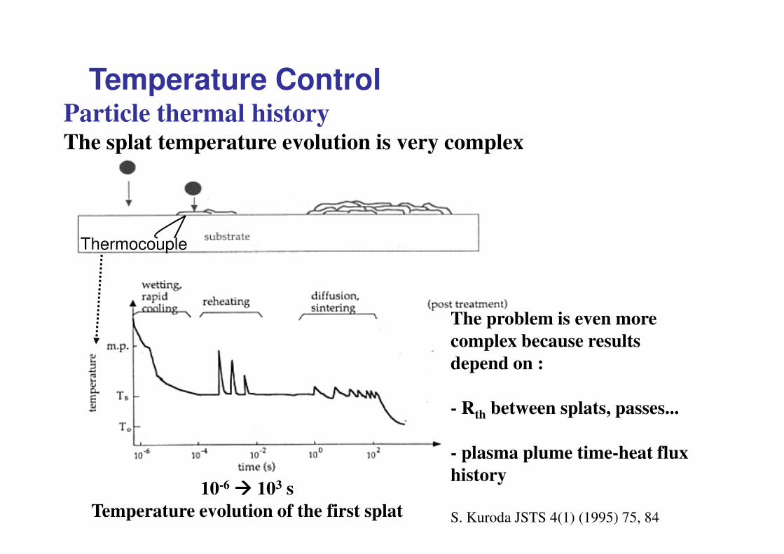
Particle thermal historyThe splat temperature evolution is very complex
Temperature Control
Thermocouple
The problem is even more complex because results depend on :
- Rth between splats, passes...
- plasma plume time-heat flux history
S. Kuroda JSTS 4(1) (1995) 75, 84
10-6 ���� 103 sTemperature evolution of the first splat
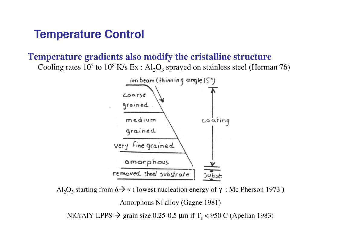
Temperature gradients also modify the cristalline structureCooling rates 105 to 108 K/s Ex : Al2O3 sprayed on stainless steel (Herman 76)
Temperature Control
Al2O3 starting from �� � ( lowest nucleation energy of γ : Mc Pherson 1973 )
Amorphous Ni alloy (Gagne 1981)
NiCrAlY LPPS � grain size 0.25-0.5 μm if Ts < 950 C (Apelian 1983)
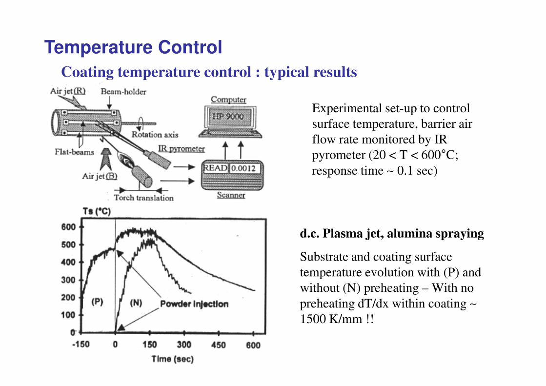
Experimental set-up to control surface temperature, barrier air flow rate monitored by IR pyrometer (20 < T < 600�C; response time ∼ 0.1 sec)
Coating temperature control : typical results
Temperature Control
d.c. Plasma jet, alumina spraying
Substrate and coating surface temperature evolution with (P) and without (N) preheating – With no preheating dT/dx within coating ∼1500 K/mm !!

Conclusions
Plasma spraying is based on many different fields:
• plasma physics, fluid mechanics and thermal science,
(3D and transient phenomena),
• plasma chemistry,
i l i
Conclusions
• materials science,
• solid mechanics (residual stresses),
• powders science,
• sophisticated measuring devices: emission spectroscopy,
fast pyrometers, fast cameras, …(phenomena in the μs
and μm range)
• Difficulty: coating properties depend on times ranging from 10ns to few hours or even days!
In spite of all these difficulties since more than one decade great strides have been made in coatingsscience.
Conclusions
Sensors able to work in harsh conditions of spray booths have been developed improving coatings reliability and consistency
Sales increase regularly by about 10%/year