Embed Size (px)
Citation preview

CHINA FOUNDRY Vol.7 No.1
52
Convection effect on dendritic growth using phase-field method
Male, born in 1974, Ph.D, associate professor. He graduated from Hunan University in 1998, and obtained his master degree in 2002. He gained his doctor degree from Lanzhou University of Technology in 2006. Currently, his more than 30 papers has been published in journals such as Acta Physica Sinica, Trans. Nonferrous Met. Soc. China, Materials Transactions, Rare Metal Materials and Engineering, etc. His research interest mainly focuses on numerical simulation of solidification structure using phase-field theory.
E-mail: [email protected].
Received: 2009-04-19; Accepted: 2009-10-20
*Zhu Changsheng
*Zhu Changsheng1,2, Wang Zhiping1, Gui Jin1 and Xiao Rongzhen1
(1. State Key Laboratory of Advanced Non-ferrous Metal Materials in Gansu, Lanzhou University of Technology, Lanzhou 730050,
China; 2. CAD Center, Lanzhou University of Technology, Lanzhou 730050, China)
Abstract: Phase-field model was employed to quantitatively study the effect of convection on pattern selection and growth rate of 2D and 3D dendrite tip, as well as the effect of the different convection velocity on the dendritic growth. The calculated results show that crystal is asymmetric in the priority direction of growth under flow. The dentritic growth is promoted in the upstream region and suppressed in the downstream region. Convection can cause deviation in the dendrite growth direction and the preferred direction of the columnar crystals. It has been found that both primary dendrite stem and secondary dendrite arm deflect significantly towards upstream direction, secondary dendrite arm in upstream direction is more developed than the primary dendrite in downstream direction.
Key words: phase-field model; convection; microsegregation; numerical simulationCLC number: TP391.9 Document code: A Article ID: 1672-6421(2010)01-052-05
In fact, crystal growth is a macroscopic transportation process of heat, mass and momentum. Such transportation
process plays a limited role in controlling crystal growth rate and affecting the stability of growth interface [1]. In contrast to the momentum convection, convection of liquid metal caused by either temperature difference or concentration difference has a significant impact on structure and composition of segregation during solidification [2].
Dendrite structure can be significantly affected by the existence of convection[3]. A strong convection (e.g. turbulence) erodes dendrite arm and promotes the equiaxed grain structure. It is well known that alloy with high solute concentration could form more equiaxed crystal under flow, either mechanically or electro-magnetically. A weak convection could alter primary dendrite arm spacing and the growth direction of secondary dendrite arm. More specifically, secondary dendrites are more developed in the upstream region of convection while its growth is restrained in a downstream side of the primary dendrites.
It has been over two decades that phase-field model was developed and applied to simulating solidification microstructure. Like any theoretical model with strong application background, phase-field model has developed from pure substances to binary alloy systems, from dendrite-free structure to directionally solidified microstructure, etc. and achieved prominent advancement. Though it was initially ignored (mainly due to the complex mathematical definition), flow field was more recently incorporated into phase-field model to simulate the impact of melt convection on resultant microstructure [1, 2, 5, 7-13].
This paper focuses on simulating the effect of convection on final microstructure pattern and a quantifying advancing speed of 2D and 3D dendrite tip. A phase-field model with embedded flow field module was employed to attain the law of dendrite growth under various convection conditions.
1 Numerical method
1.1 Simulation modelKarma and Rappel[4] developed a phase-field model coupling with thermal noise. Although some previous phase-field simulations have obtained dendritic side-branches that are similar with experimental observations [6-8], those side-branches were generated by either numerical noise or randomly driving the tip. In Karma and Rapple’s model, thermal noise was introduced in a thermodynamically consistent manner using the Langevid formalism, and the nonconserved noise and conserved noise was added to the phase equation and the energy conservation equation, respectively, as shown in eqs. (1) and (2):

Research & DevelopmentFebruary 2010
53
Whereφ is a continuous order parameter,φ∈[-1,1] and φ= -1 for the liquid; 1 for the solid; 0 for the interface. The dimensionless temperature u is defined as u =(T-TM)/(L/
Cp), where TM, L and Cp are the melting temperature, latent and specific heat at constant pressure, respectively. D is the thermal diffusivity, λ is coupling constant, τ is the interface energy anisotropy, and W is the interface kinetics anisotropy,
both of them are functions of interfacial normal: n .
Where 4 is anisotropy coefficient, is motion time of atomic at the interface, θ
and q are the thermal noise vectors, which
also follow Gaussian distribution, as shown in eqs. (5) and (6).
Where kB is the Boltzmann constant, is the delta function,
t and t' are the growing time of dendrite, r and r ′ are the position vectors. Using w0 as a length scale and 0 as a time scale, all
dimensional variables can be converted into their dimensionless forms as, r /w0→ r, t /τ →t, Dτ 0 /w0
2→D, τ θ →θ , qτ 0 / w0→ q ,
the dimensionless variations in thermal noise vector are then given by:
Where is Kronecker delta, Fu is the magnitude of the thermal noise defined as:
Where d0 is the capillary length and Fexcp is experimental value of the magnitude for thermal noise. The conservation equations for mass and momentum take the following form[1]:
Where P is the pressure, V is the velocity vector,ρ is density
and µ is kinetic viscosity of the melt. The term dM 1 is a dissipative interfacial force per unit volume and is modeled as:
0τ
δ
τ
mnδ
2
0
0
2
0
0
2
0
2
2
2
0
2
2
=
==
wdF
wd
dLCTk
wLCTk
F excp
pMBpMB
u
Where the constant h is found to be 2.757 by an asymptotic analysis of plane flow on the diffuse interface.
1.2 Initial condition and boundary conditionFor an initial nucleus of the radius r0,
Where x and y are the coordinate axis, and Vx, Vy is component convection velocity along x and y axis respectively. The initial interface is defined as the round area (r0=10) at the center of the square and standing for the initial nucleus. Supercooled melt enters the area from the top boundary with a uniform velocity U, and exits at the bottom boundary. The initial condition of simulation area is shown as Fig.1.
(1)
(2)
(3)
(5)
(7)
(4)
(6)
(8)
(9)
(10)
(12)
(13)
Fig.1: The initial condition of simulation area
The Zero-Neumann boundary conditions forφ , m and P
are applied to the boundaries of the computational area [6]. The phase field eq. (1) is solved using Euler algorithm, and ADI algorithm is applied for the heat eq. (2), while the mass and momentum equations are solved numerically using the standard SIMPLE method[1]. The space step is selected as Δx, Δx≤δ 0, the time step Δt , Δt≤Δx0
2/4 is specified in such a
way that for keeping stable under time-step iterations. During the computation, the number of grid nodes is determined by dendrite size and increases with the dendritic size.
The phase-field computational parameters used in calculation are listed in Table 1.
2 Numerical results and discussion
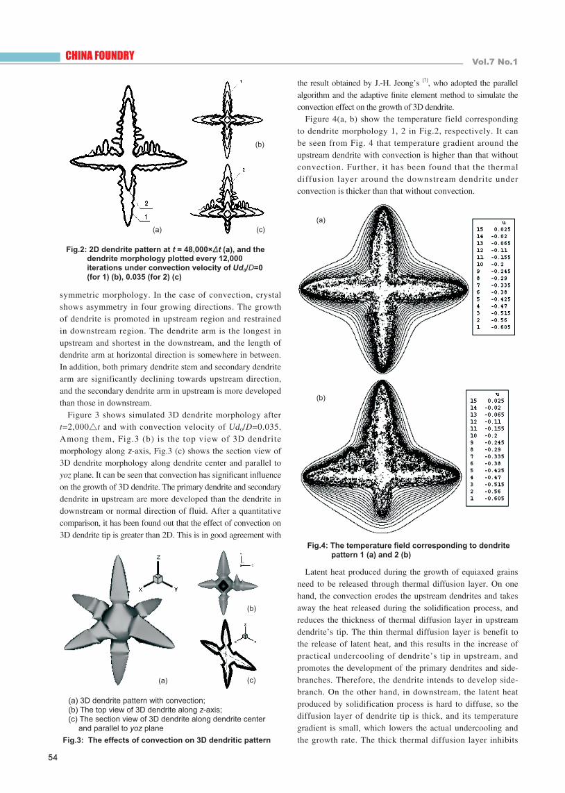
2.1 The effect of convection on dendrite morphology and its temperature fieldFigure 2 (a) shows the dendrite morphology after t = 48,000Δt under the convection velocity Ud0/D = 0 (for 1), 0.035 (for 2). Figures 2(b), (c) show the dendrite morphology while the reiterations is 12,000 and the convection velocity is Ud0/D=0, 0.035 respectively. It can be seen that in the case of no convection (Ud0/D=0), the crystal grows symmetrically in four preferentially growing directions, the distribution of diffusion layer near each dendrite tip is the same, and the dendrite shows
Table 1: Phase-field and computational parameters
Para. 4ε Δ d0/w0 D τ 0 λ Δx=Δy Δt
Value 0.05 -0.55 0.277 1 1 6.4 0.4 0.016
),(])()()([ 2
,
trnWnWx
myxm
θφ
φ +∂∂
∂∇∂+ ∑
=
),(212 trq
tuD
tu
⋅∇−∂∂
+∇=∂∂ φ
( ) ])()(
3141[31)( 4
44
4
4
40 φφφ
εεε
∇
∂+∂−
+−= yxWnW
])()(
3141[)( 4
44
4
40
φφφ
ε
ε
ετ∇
∂+∂−
+= yxn τ
)'()(2),(),(2
2
ttrrLTC
Dktrqtrq mn
mp
Bnm −′−=′ δδδ
)'()(2),(),( ttrrFtrtr mn −′−=′ δδδθ θ u
)'()(2),(),( ttrrFtrtr mn −′−=′ δδδθ
uθ
τ
U
φ( )
VW
hM d
2
2
1
12 φµφ −−= ( )
])([)1)](1([)( 222 φφφφφτ ∇∇+−−−=∂ nWn t
uλ
)'()(2),(),(2
2
ttrrLTC
Dktrqtrq mn
p
Bnm −′−=′ δδδ M
01 =−⋅∇ V
( )
(11)
PVVVt
∇−−=∇⋅−+−∂∂ φ
ρφφ 1111
dMV 11 +−∇∇+
φµ
[ ][ ]
( ) ( ) ( )
( )
>+===∆−=−=≤+=====
2
0
22
2
0
22
00100011
ryxPUVVuryxPVVu
yx
yx
φφ
CHINA FOUNDRY Vol.7 No.1
54
symmetric morphology. In the case of convection, crystal shows asymmetry in four growing directions. The growth of dendrite is promoted in upstream region and restrained in downstream region. The dendrite arm is the longest in upstream and shortest in the downstream, and the length of dendrite arm at horizontal direction is somewhere in between. In addition, both primary dendrite stem and secondary dendrite arm are significantly declining towards upstream direction, and the secondary dendrite arm in upstream is more developed than those in downstream.
Figure 3 shows simulated 3D dendrite morphology after t=2,000△t and with convection velocity of Ud0/D=0.035. Among them, Fig.3 (b) is the top view of 3D dendrite morphology along z-axis, Fig.3 (c) shows the section view of 3D dendrite morphology along dendrite center and parallel to yoz plane. It can be seen that convection has significant influence on the growth of 3D dendrite. The primary dendrite and secondary dendrite in upstream are more developed than the dendrite in downstream or normal direction of fluid. After a quantitative comparison, it has been found out that the effect of convection on 3D dendrite tip is greater than 2D. This is in good agreement with
Fig.2: 2D dendrite pattern at t = 48,000×Δt (a), and the dendrite morphology plotted every 12,000 iterations under convection velocity of Ud0/D=0 (for 1) (b), 0.035 (for 2) (c)
Fig.3: The effects of convection on 3D dendritic pattern
(a)
(b)
(c)
the result obtained by J.-H. Jeong’s [7], who adopted the parallel algorithm and the adaptive finite element method to simulate the convection effect on the growth of 3D dendrite.
Figure 4(a, b) show the temperature field corresponding to dendrite morphology 1, 2 in Fig.2, respectively. It can be seen from Fig. 4 that temperature gradient around the upstream dendrite with convection is higher than that without convection. Further, it has been found that the thermal diffusion layer around the downstream dendrite under convection is thicker than that without convection.
Fig.4: The temperature field corresponding to dendrite pattern 1 (a) and 2 (b)
Latent heat produced during the growth of equiaxed grains need to be released through thermal diffusion layer. On one hand, the convection erodes the upstream dendrites and takes away the heat released during the solidification process, and reduces the thickness of thermal diffusion layer in upstream dendrite’s tip. The thin thermal diffusion layer is benefit to the release of latent heat, and this results in the increase of practical undercooling of dendrite’s tip in upstream, and promotes the development of the primary dendrites and side-branches. Therefore, the dendrite intends to develop side-branch. On the other hand, in downstream, the latent heat produced by solidification process is hard to diffuse, so the diffusion layer of dendrite tip is thick, and its temperature gradient is small, which lowers the actual undercooling and the growth rate. The thick thermal diffusion layer inhibits
(a)
(b)
(c)
(a)
(b)
(a) 3D dendrite pattern with convection; (b) The top view of 3D dendrite along z-axis; (c) The section view of 3D dendrite along dendrite center
and parallel to yoz plane

Research & DevelopmentFebruary 2010
55
the release of latent heat, therefore constrains the interface disturbance and suppresses the growth of the primary dendrites and side branches. In the mean time, with the increase of forced flow (i.e. the enhanced convection) the erosion of upstream dendrites and the diffusion of heat are promoted, which results in the reduced temperature at the dendrite tip in upstream and faster growth rate of upstream dendrites.
2.2 Effect of convection velocity on the growth of dendriteConvection affects the growth rate of upstream, normal and downstream dendrites. Figure 5 shows the dendrite morpho logy a f t e r t =36 ,000Δt , and the f low ra t e s corresponding to dendrite morphology 1-4 in Fig.5 are Ud0/D=0, 0.027, 0.035, 0.070, respectively. As discussed previously, compared with the dendrite morphology without convection (dendrite 1 in Fig.5), the dendrite grown under convection shows asymmetric morphology, which becomes more obvious with the increase of flow rate. This is because that with increase of the flow rate, the growth rate of upstream dendrites increases, and the primary dendrite and secondary dendrite are further developed. In contrast, with the increase of flow rate, the growth rate of downstream dendrites reduces, and the primary dendrite and secondary dendrite became under-developed - especially the secondary dendrite in opposite to the convection direction. Moreover, convection also influences the growth of dendrite perpendicular to the flow direction. That is with the increase of flow rate, the horizontal dendrite tip deviates towards the flow direction.
convection on the growth of the dendrite tip quantitatively, the growth rates and radius of the upstream dendrite tip, the normal dendrite tip and the downstream dendrite tip were calculated under the condition of a constant flow rate of Ud0/D=0.027. The results are compared with those without convection, as shown in Figs. 6 and 7. Under traditional solidification process, the undercooling at dendrite tip front is big in the initial stage of solidification, so as to promote the nucleation and growth. Because the initial nucleus in this study is optional and the growth of grain does not reach stability in the primary stage of dendrite growth, the growth rate is uncertain and the tip radius is also unstable. With the growth of dendrite, latent heat released from the solidification process rapidly reduces the undercooling at the dendrite tip front, then the undercooling at each dendrite tip becomes stable and the tip radius also reaches a steady status.
Fig.5: The dendritic pattern under different flow rate
Convection also affects the arm spacing of both primary dendrite and secondary dendrite. The secondary dendrites are more developed in the upstream side of the dendrites. On the contrary, the growth of secondary dendrites is restrained in the downstream side of the primary dendrites. Similarly, convection can also cause deviation in the dendrite growth direction and the preferred direction of the columnar crystals. Both primary dendrite stem and secondary dendrite arm significantly deflect towards upstream direction, and the secondary dendrite arm in upstream is even more developed than the primary dendrite in downstream.
2.3 Effect of convection on the dendrite tip’s growth rate and the radiusDuring the growth of dendrites, the growth rate of the dendrite tip changes with time. In order to analyze the effect of
Fig.6: The growth rate of dendrite tip with/without convection
Fig.7: The dendrite tip’s radius changing with growing time
After stable grain growth and before it approaches the mesh boundary, the grain growth rate has the trend of slightly increase due to the facts of given boundary conditions and that the undercooling of boundary is lower than that at center. Therefore, no further grain growth rate data is calculated after the dendrite growth reaches a steady state to save computing time.
3 Conclusions(1) The phase-field model coupling flow field was studied,
and the effect of forced convection on morphology variation and growth rate of 2D dendrite tip were quantitatively

CHINA FOUNDRY Vol.7 No.1
56
simulated. It has been found out that dendrite growth is consistent with crystallization theory, which confirms the validity of utilizing phase-field model for stimulating the growth of 3D dendrite. Further, the simulation data about the effect of convection on dendrite tip morphology and size is in good agreement with related literatures.
(2) Convection can affect the growth direction of primary dendrite arm and secondary dendrite arm. In addition, the secondary dendrites in the upstream side of the dendrites are more developed. On the contrary, the growth of secondary dendrites in the downstream side of the primary dendrites is suppressed. It is also found that convection can cause deviation in the dendrite growth direction and the preferred direction of the columnar crystals.
(3) In the future work, the phase-field model need to be optimized and implemented with some factors, such as large Reynolds number, flow of melt, heterogeneous nucleation and multiphase intergrowth etc. In addition, similar experimental work needs to be designed and compared with simulation data using phase field model.
References [1] Tong X, Beckermann C, Karma A. Velocity and shape selection
of dendritic crystals in a forced flow. Physical Rev. E, 2000, 61(1): 49-52.
[2] Joeng J–H, Goldenfeld N, Dantzig J A. Phase field model for three-dimensional dendritic growth with fluid flow. Phys. Rev. E, 2001,64 (041602): 1-14.
[3] Zhu Changsheng, Wang Zhiping, Liu Baicheng, et al. Effects
of phase-field parameters of side branching using phase field simulation. Chinese Journal of Mechanical Engineering, 2005, 41: 30-34. (in Chinese)
[4] Karma A, Rappel W J. Phase-f ield model of dendrit ic sidebranching with thermal noise. Physical Rev. E, 1999, 60 (4): 3614-3625.
[5] Tong X, Beckermann C, Karma A, Li Q. Phase-filed simulations of dendritic crystal growth in forced flow. Phys. Rev. E, 2001, 63(061601): 1-16.
[6] Zhu Changsheng, Wang Zhiping, Jing Tao. Phase-field simulation of dendritic sidebranching induced by thermal noise. Trans. Nonferrous Met. Soc. China, 2004, 12(6): 1106-1110. (in Chinese)
[7] Jeong J H, Dantzig J A, Goldenfeld N. Dendritic growth with fluid flow in pure materials. Metall. Mater. Trans. A, 2003 (34): 459-466.
[8] Tönhardt R, Amberg G. Phase-field simulation of dendritic growth in a shear flow. J. Cryst. Growth, 1998, 194 (1): 406-425.
[9] Anderson D M, McFadden G B, Wheeler A A. A phase-field model of solidification with convection. Physica D, 2000, 135(1-2):175-194.
[10] Beckermann C, Diepers H J. Modeling melt convection in phase-f ield simulations of sol idif ication. Journal of Computational Physics, 1999,154(2): 468-496.
[11] Diepers H J, Beckermann C, Steinbach I. Simulation of convection and ripening in a binary alloy mush using the phase-field method. Acta Mater., 1999, 47(13): 3663-3678.
[12] Lu Yili. Phase-field modeling of three-dimensional dendritic solidification coupled with fluid flow [Dissertation]. Iowa USA: The University of Iowa, 2002.
[13] Li Q, Beckermann C. Modeling of free dendritic growth Succionitrile-acetone alloys with thermosolutal melt convection. J. Cryst. Growth, 2002, 236: 482-498.
This project was supported by National Natural Science Foundation of China under contract No.10964004, Research Fund for the Doctoral Program of Higher Education of China under contract No.20070231001, Natural Science Foundation of Gansu province under contract No. 096RJZA104, and Doctoral Fund of Lanzhou University of Technology under contract No.SB14200801.


![L 18 Thermodynamics [3] Review Review Heat transfer processes Heat transfer processes –convection –conduction –radiation Greenhouse effect Greenhouse effect](https://img.pdfslide.us/doc/110x75/56649f0c5503460f94c1fbfb/l-18-thermodynamics-3-review-review-heat-transfer-processes-heat-transfer.jpg)


![COMBINED NATURAL CONVECTION AND RADIATION WITH … · the effect of natural convection with radiation. Tan and Howell [4] used the product-integral method and finite difference method](https://img.pdfslide.us/doc/110x75/5e88155ab45a93369773bd11/combined-natural-convection-and-radiation-with-the-effect-of-natural-convection.jpg)