Embed Size (px)
Citation preview

Product Data Document1660DS-7e / D301292X012March 2012 - Page 1
Website: www.EmersonProcess.com/Remote
Remote Automation Solutions
ControlWave® XFCGas Flow Computer
ControlWave XFC comes in a very compact, explosion-proof package. Smart DP/P sen-
sor assembly is shown in this photo.
Now available with Integral
P/T or DP/P/T MeasurementControlWave® XFC, from Emerson Process Man-agement is a cost effective, competitive solution when requirements call for a chart replacement or fl ow computer in a compact, explosion-proof pack-age.
Additionally, ControlWave XFC provides extended capabilities, such as a second meter run or plunger lift control, while maintaining the convenience and simplicity of an integrated, explosion-proof installa-tion.
ControlWave XFC Overview
Hardware/Packaging FeaturesSmart, gauge pressure or DP/P sensor • assembly can be removed and replaced, independently of the "top end" assembly.
Precision RTD interface provides very accurate • process temperature measurement.
Wide, 6.0 to 30.0 Vdc operating input voltage • range works with a broad range of power sources.
Very low power consumption minimizes costs of • solar/battery power systems.
Three serial communication ports are standard.•
Optional I/O includes 2 DI, 2 High-speed • Counter inputs and 4 DO as well as an additional 3 AI and 1 AO.
Integral 2-line LCD operates in a continuous • cycle mode.
Operating temperature range is -40 to 176ºF • (-40 to 80ºC).
Class I, Division 1 (explosion-proof) and • Division 2 NI approved.
Readily integrates with Emerson’s 2808 and • 3808 MVT low power transmitters for explosion-proof installations.
Firmware/Software FeaturesControlWave XFC is pre-programmed to meet • API 21.1 requirements for a two-run metering station with networking via BSAP or Modbus.
PC web style menu pages are pre-confi gured • for all user operations.
Using our ControlWave Designer, IEC 61131-3 • programming environment, any user or third party can modify the standard application or create a completely customized program—and full support from Emerson is available, every step of the way.
Additional, standard application programs will • be introduced on a continual basis.
Product Data Document1660DS-7e / D301292X012March 2012 - Page 2 ControlWave® XFC
Remote Automation SolutionsWebsite: www.EmersonProcess.com/Remote
Application Areas
ControlWave XFC is appropriate to all applications for flow computers, including those that require process control or extension to two meter runs, for example:
Production wells•
Injection wells•
Production optimization applications•
Off-shore platforms•
Separation plants•
Compressor stations•
Storage facilities•
Transmission metering stations•
Distribution/LDC metering/gate stations•
Using the gauge pressure sensor, ControlWave XFC provides accurate, P/T measurement for linear meters, including positive displacement, turbine and ultrasonic technologies. The multivariable, DP/P sensor applies best to orifice metering, where accurate, three-variable (DP/P/T) measurement is required.
Package Description
ControlWave XFC is ordered using a model number specification. The complete model number speci-fication is included toward the end of this product data.
Standard equipment includes an explosion-proof housing, two-board electronics assembly with 3 se-rial ports RTD interface, 2-line LCD, and the stan-dard API 21.1 EFM application program. Emerson’s smart sensor assembly, which provides measure-ment of gauge pressure or differential pressure plus static pressure, is also standard equipment.
The model number additionally allows a user to specify the following:
Sensor upper range limits•
Wetted parts material, stainless steel or • Hastelloy C
Optional manifold adapters•
Optional mounting bracket•
Standard application program•
I/O configuration choices are no I/O; 2 DI, 2 • HSC, 4 DO; and 2 DI, 2 HSC, 4 DO plus 3 AI and 1 AO.
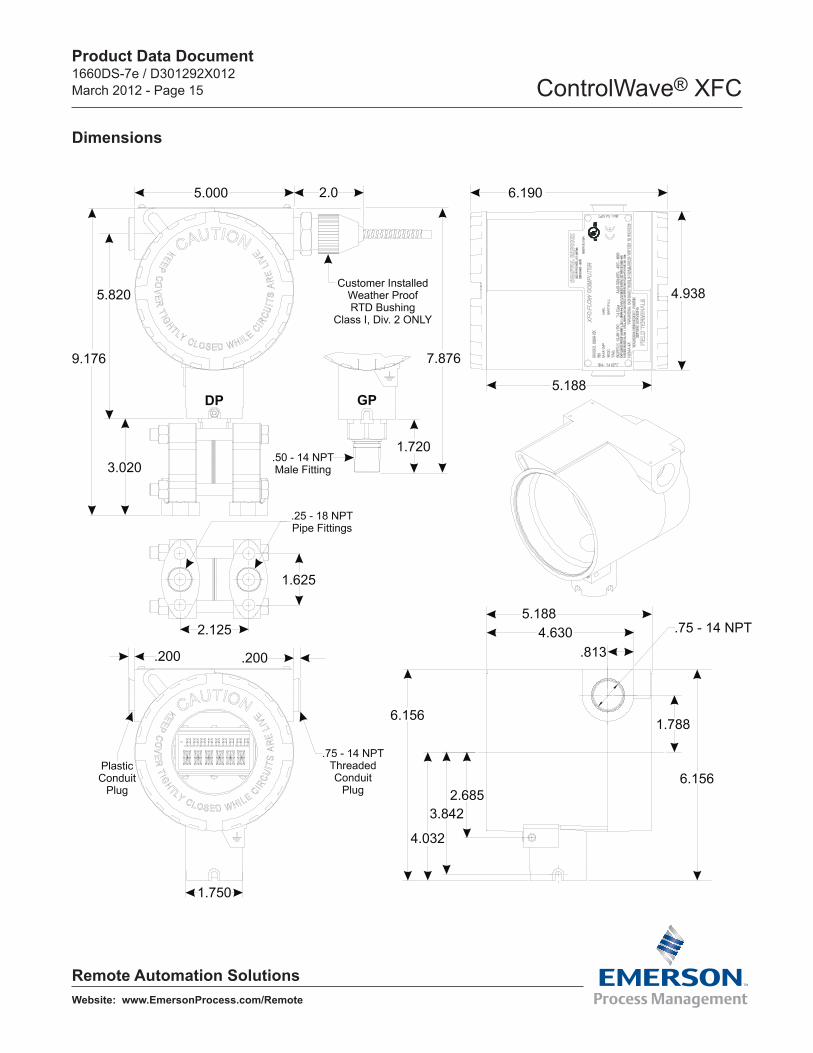
Specifications – PackageDimensions: Please see the diagram on page • 14
Clearance: Please allow at least 2.5” space on • either side for cabling.
Dimensions: MVT Wet End: 3” H x 3¾” W x 2½” • D
Weight: 12 lbs.•
Mounting: Pipe-mounting or direct-mounting is • recommended; a 2” pipe-mount kit is optional.
Housing: Low copper aluminum with ployester • paint
Specifications – Operating EnvironmentWide operating power input voltage range of • 6.0 to 30.0 Vdc. Shutdown sequence occurs at 5.46 Vdc nominal.
Power input surge suppression: 30V transorb • to ground meets ANSI/IEEE C37.90-1978.
Fuse: 0.375 A slow blow.•
Operating Temperature Range: -40 to 176ºF • (-40 to 80ºC).
Operating Humidity Range: 10 to 95% RH non-• condensing.
Vibration Rating: Maintains proper operation • while subjected to a 2.0g acceleration over 10-150 Hz and 1.0g acceleration over 150-2000 Hz.
RFI Immunity: In conformity with IEC 61000-4-3 • Level 2 80 MHz to 1000 MHz.

Product Data Document1660DS-7e / D301292X012March 2012 - Page 3 ControlWave® XFC
Remote Automation SolutionsWebsite: www.EmersonProcess.com/Remote
ESD: Field connected circuits meet the • requirements of IEC 61000-4-2 for ESD withstand capability up to 4KV.
Nema Rating: Nema 4, 4x and 7.•
Hazardous Area ApprovalsExplosion-proof for operation in Class I, Division • 1 Hazardous Areas: UL/CUL Approved.
Non-incendive for Class I, Division 2 Hazardous • areas: UL/CUL Approved.
Selection Item Descriptions and Specifications
Emerson’s Sensor Assembly
The sensor assembly is Selection “ABC” in the model specification, e.g. “022” for the 100 psi gauge pressure sensor or "142" for a 300" DP/2000 psig static pressure multivariable sensor assembly.
Using the integral sensor assembly is the easiest implementation for a single meter run; however, the standard application program also allows use of external transmitters.
Multiple-run systems can use the integral sensor assembly for the first run and an external, smart multivariable transmitter, such as the 3808 MVT from Emerson(which includes the exact same sen-sor assembly), for additional meter runs.
If the sensor assembly requires a repair, the user
can change it out and continue operating with the "top end" electronics, including flow information, alarms and historical archives, all intact.
Emerson recommends that users practice “depot level” service, in other words, that the sensor as-sembly be removed and replaced at the user’s shop rather than out at the site.
Each sensor assembly has a nine-digit part number, which can be used to specify a replacement part (please refer to the last page of this product data).
Physical Specifications – MVT AssemblyFlange Material: Hastelloy C or 316 Stainless • Steel
Flange Bolt Material: Hastelloy C or 316 • Stainless Steel
Diaphragm Material: Hastelloy C or 316 • Stainless Steel
Fill Medium: DC 200 Silicone•
Flange Process Connections: ¼” NPT•
Connects to the main electronics via a • dedicated SPI bus cable.
Note: Wetted parts materials, Hastelloy C or Stain-less Steel, are specified in Selection “D.”
Accuracy and Performance Specifications – Gauge Pressure or Differential Pressure/ Static Pressure
Combined effects of nonlinearity, • nonrepeatability and hysteresis at reference pressure and over the operating temperature range (0.035% for 1000 psi SP range): GP, DP and SP linear mode: ±0.075% of Calibrated Span or 0.015% of URL, whichever is greater.
Temperature effect on Static and Differential • pressure: ±0.21%URL (0.17% for 1000 psi SP range) maximum combined shift of zero and span with an ambient temperature change of 60ºC (108ºF)
Static Pressure Effects On Differential Pressure: • DP/P Multivariable Sensor Assembly

Product Data Document1660DS-7e / D301292X012March 2012 - Page 4 ControlWave® XFC
Remote Automation SolutionsWebsite: www.EmersonProcess.com/Remote
Zero error: ±0.1% URL, for a change in static pressure of 1000 psi; Span error: ±0.1% reading, for a change in static pressure of 1000 psi
Long Term Stability at Constant Conditions: • ±0.1% URL/Year typical
Mounting position effect: ±2 in H2O maximum, • which can be calibrated out.
Ripple and noise: Per ISA 50.1 Section 4.6•
Sensor Assembly Wetted Parts Material
Selection “D” allows the user to choose the material used in the flange bolts, flanges and diaphragm in the sensor assembly. Materials are 316 stainless steel and Hastelloy C.
Processor/Main Electronics
The electronics assembly consists of two circuit boards with the CPU, LCD display, communication, dc/dc power system controller functions and the I/O functions all installed within the explosion-proof housing.
CPU/System Controller specifications are listed here. For information and specifications on the I/O, please refer to the description for Selection “K,” “I/O CONFIGURATION,” on page 6.
Specifications for CPU/System Controller
32-bit ARM9TDMI RISC Core Processor • running at 14 MHz
Serial Real Time Clock Accurate to 5 seconds/• month at 25 ºC
512 KB Flash Boot/Downloader•
2 MB SRAM•
8 MB Simultaneous Read/write Flash•
Backup Battery for Real Time Clock and SRAM: • 300 mA-Hour Lithium Coin Cell, 4000 Hour
Backup Time
3 Serial Communication Ports (see below for • further information)
6.0 to 30.0 Vdc Power Supply with Power Fail • Sequencer
Two-line LCD with nine, seven-segment • numeric characters plus polarity on line 1 and six, fourteen-segment alphanumeric characters on line 2.
Information on the Serial Ports
COM1:RS 232•
Three wire interface•
300 to 115.2K baud rates•
Physical Interface is on the main termination • assembly.
COM2:RS 232 •
300 to 115.2K baud rates•
Physical Interface is on the main termination • assembly.
Supports RTS, CTS, DTR, and DCD modem • control signals
RS 232 transceivers are enabled by the port’s • DTR.
DCD remains active in power-down mode.•
COM3:RS 485, 2-wire•
300 to 115.2K baud rates•
Physical Interface is on the main termination • assembly.
Product Data Document1660DS-7e / D301292X012March 2012 - Page 5 ControlWave® XFC
Remote Automation SolutionsWebsite: www.EmersonProcess.com/Remote
ControlWave XFCStandard Application Program
Selection “EF” allocates two digits with the expecta-tion that we will offer a number of standard appli-cations in the future. Currently, the two-run M&R program is the only one available.
ControlWave XFC is shipped with the program (.MWT fi le) loaded in Flash and the Flash Confi gu-ration Program (FCP) also loaded.
For users who expect to use their own program, ControlWave XFC can also be ordered without an application program.
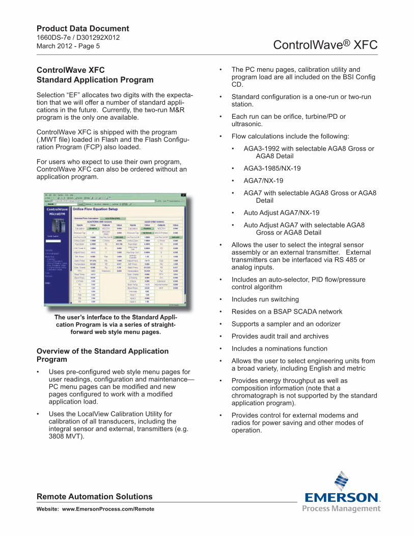
The user’s interface to the Standard Appli-cation Program is via a series of straight-
forward web style menu pages.
The user’s interface to the Standard Appli-
Overview of the Standard ApplicationProgram
Uses pre-confi gured web style menu pages for • user readings, confi guration and maintenance—PC menu pages can be modifi ed and new pages confi gured to work with a modifi ed application load.
Uses the LocalView Calibration Utility for • calibration of all transducers, including the integral sensor and external, transmitters (e.g. 3808 MVT).
The PC menu pages, calibration utility and • program load are all included on the BSI Confi g CD.
Standard confi guration is a one-run or two-run • station.
Each run can be orifi ce, turbine/PD or • ultrasonic.
Flow calculations include the following:•
AGA3-1992 with selectable AGA8 Gross or • AGA8 Detail
AGA3-1985/NX-19•
AGA7/NX-19•
AGA7 with selectable AGA8 Gross or AGA8 • Detail
Auto Adjust AGA7/NX-19•
Auto Adjust AGA7 with selectable AGA8 • Gross or AGA8 Detail
Allows the user to select the integral sensor • assembly or an external transmitter. External transmitters can be interfaced via RS 485 or analog inputs.
Includes an auto-selector, PID fl ow/pressure • control algorithm
Includes run switching•
Resides on a BSAP SCADA network•
Supports a sampler and an odorizer•
Provides audit trail and archives•
Includes a nominations function•
Allows the user to select engineering units from • a broad variety, including English and metric
Provides energy throughput as well as • composition information (note that a chromatograph is not supported by the standard application program).
Provides control for external modems and • radios for power saving and other modes of operation.
Product Data Document1660DS-7e / D301292X012March 2012 - Page 6 ControlWave® XFC
Remote Automation SolutionsWebsite: www.EmersonProcess.com/Remote
Communication Port Configuration for the Standard Application Program
COM1 – Local RS 232 port for configuration via a PC. Flash configuration is BSAP Slave, 115.2K baud rate.
COM2 – RS 232 Network port with Flash configu-ration of BSAP Slave, 9600 baud. The standard application program is compatible with an external communication device via RS 232.
COM3 – RS 485 port with Flash configuration of BSAP Master at 9600 baud. The standard appli-cation program assumes that a 3808 MVT smart multivariable transmitter is to be interfaced to this port.
Hazardous Area Certification
Class I, Division 1 certification via the explosion proof packaging and Class I, Division 2 certification via non-incendive electronics are specified in selec-tion “G.”
Manifold Adapters
Optional manifold adapters, which come in a set of two, one for each flange for the DP/P sensor as-sembly, are available in stainless steel and specified in selection “H.”
Mounting Bracket
An optional mounting bracket, which affixes to the neck of the housing and allows installation on a wall or 2” pipe, can be specified in selection “J.”
I/O Configuration
In selection “K,” the user can choose a configuration without I/O, one with 2 DI, 2 HSC and 4 DO, and one with 2 DI, 4 DO, 2 HSC plus 3 AI and 1 AO.
It is recommended that users select an I/O configu-
ration if use of any I/O is anticipated in the future because addition of the points requires a change-out of the I/O card—due to hazardous area certifi-cation requirements, that can be done only at the factory.
ControlWave XFC I/O Specifications
Discrete InputsNumber of points: 2•
Input configuration: Internally sourced dry • contact
Input filtering: 15 milliseconds•
Input current: 60 uA nominal.•
“0” state voltage: Below 1.5V•
“1” state voltage: Above 1.5V •
Maximum Scan Rate: once per second•
Electrical isolation: None•
Surge Suppression: 30V transorb between • signal and ground meets ANSI/IEEE C37.90-1978
Terminations: Pluggable Terminal block • accommodates up to 14 gauge wire size
Discrete OutputsNumber of points: 4•
Configuration: Open Drain MOSFET, externally • sourced
Maximum load current: 400 mA at 30 Vdc•
Maximum Update Rate: once per second•
Electrical isolation: None•
Surge Suppression: 30V transorb between • signal and ground meets ANSI/IEEE C37.90-1978
Terminations: Pluggable Terminal block • accommodates up to 14 gauge wire size
Product Data Document1660DS-7e / D301292X012March 2012 - Page 7 ControlWave® XFC
Remote Automation SolutionsWebsite: www.EmersonProcess.com/Remote
High Speed Counter InputsNumber of points: 2•
Input Range: Internally source dry contact input•
Frequency range: 0 – 10,000 Hz •
Input filtering: 20 microseconds•
One shot pulse conditioned signal to MSP • counter
Signal Conditioning: Debounce circuit for • contact closures and bandwidth limiting for counter input
Input current: 200uA•
“0” state voltage: Above 1.5V•
“1” state voltage: Below 1.5V •
Electrical isolation: None•
Surge Suppression: 30V transorb between • signal and ground meets ANSI/IEEE C37.90-1978
Terminations: Pluggable Terminal block • accommodates up to 14 gauge wire size
Analog InputsPoint Count: 3 Inputs, Single ended•
Range: 1-5 Vdc, externally powered•
Input Impedance: 1 M ohm•
Filter: single pole•
Accuracy +/- .1% of full scale at 25ºC; +/- .2% • of full scale from -20 to 70ºC; +/- .3% of full scale from -40 to 80ºC
Maximum Scan Rate: once per second•
Surge Suppression: 9V transorb between • signal and ground meets ANSI/IEEE C37.90-1978
Terminations: Pluggable Terminal block • accommodates up to 16 gauge wire size
Analog OutputPoint Count: One analog output •
Range: 4-20mA Sink•
Maximum drive for 4-20 mA output: 450 Ohms•
Resolution: 16-bits•
Accuracy: +/- 0.1% of full scale at 25ºC; +/- • 0.2% of full scale from -20 to 70ºC, +/- 0.3% of full scale; -40 to 80ºC
Maximum Update Rate: once per second•
Surge Suppression: 9V transorb between • signal and ground meets ANSI/IEEE C37.90-1978
Terminations: Pluggable Terminal block • accommodates up to 16 gauge wire size
RTD Interface Information
A three-wire platinum RTD per DIN 43760 is sup-ported. The temperature, T, in degrees Celsius is calculated using the Resistance vs. Temperature Tables according to the DIN EN 60751 standard for Class A & B RTDs. The DIN EN 60751 equation is:
R(t) = R0 * (1 + At +Bt2) Where:
A = 3.9083 * 10-3 oC-1 B = -5.775 * 10-7 oC-2 R0 = 100ohms
In addition, the user may enter the R0, A, and B coefficients of a custom calibrated RTD, another platinum standard or a different material (Nickel, Balco or Copper).
During the RTD calibration, the user will be able to set the coefficients, restore the factory default for these coefficients, and calibrate the internal Refer-ence resistor.
RTD Input Specifications
These specifications are for the interface only, not including the RTD probe or wiring (please note that
Product Data Document1660DS-7e / D301292X012March 2012 - Page 8 ControlWave® XFC
Remote Automation SolutionsWebsite: www.EmersonProcess.com/Remote
RTD probe interchangeability can add ±0.7°C of uncertainty to the measurement).
RTD Conversion Accuracy: ± 0.1°C, or ± 0.1% • of reading, whichever is greater
Ambient temperature effect on RTD • measurement: ±0.01°C / ºC max
Long Term Stability at Constant Conditions: • ±0.25ºC / month max
Accessories
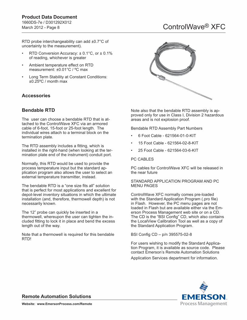
Bendable RTD
The user can choose a bendable RTD that is at-tached to the ControlWave XFC via an armored cable of 6-foot, 15-foot or 25-foot length. The individual wires attach to a terminal block on the termination plate.
The RTD assembly includes a fitting, which is installed in the right-hand (when looking at the ter-mination plate end of the instrument) conduit port.
Normally, this RTD would be used to provide the process temperature input but the standard ap-plication program also allows the user to select an external temperature transmitter, instead.
The bendable RTD is a “one size fits all” solution that is perfect for most applications and excellent for depot-level inventory situations in which the ultimate installation (and, therefore, thermowell depth) is not necessarily known.
The 12” probe can quickly be inserted in a thermowell, whereupon the user can tighten the in-cluded fitting to lock it in place and bend the excess length out of the way.
Note that a thermowell is required for this bendable RTD!
Note also that the bendable RTD assembly is ap-proved only for use in Class I, Division 2 hazardous areas and is not explosion proof.
Bendable RTD Assembly Part Numbers
6 Foot Cable - 621564-01-0-KIT•
15 Foot Cable - 621564-02-8-KIT•
25 Foot Cable - 621564-03-6-KIT•
PC CABLES
PC cables for ControlWave XFC will be released in the near future
STANDARD APPLICATION PROGRAM AND PC MENU PAGES
ControlWave XFC normally comes pre-loaded with the Standard Application Program (.pro file) in Flash. However, the PC menu pages are not loaded in Flash but are available either via the Em-erson Process Management web site or on a CD. The CD is the “BSI Config” CD, which also contains the LocalView Calibration Tool as well as a copy of the Standard Application Program.
BSI Config CD – p/n 395575-02-8
For users wishing to modify the Standard Applica-tion Program, it is available as source code. Please contact Emerson’s Remote Automation Solutions Application Services department for information.

Product Data Document1660DS-7e / D301292X012March 2012 - Page 9 ControlWave® XFC
Remote Automation SolutionsWebsite: www.EmersonProcess.com/Remote
Product Family Compatibility
ControlWave XFC is compatible with Emerson’s ControlWave family. It is fully software-compat-ible with ControlWave GFC, ControlWave EFM, ControlWave Micro and the ControlWave Process Automation Controller (PAC). The ControlWave PAC provides the highest I/O capacity and supports up to three Ethernet ports as well as redundancy.
This family compatibility is a major benefit to users whose operations include a number of larger instal-lations in addition to those that require flow comput-ers. ControlWave family products are capable of all measurement & control functions at sites such as major, custody-transfer metering stations, compres-sor stations, off-shore platforms, processing plants and storage facilities.
Users will not only appreciate the similarity in much of the hardware but will also find the documenta-tion, networking and software compatibilities to be important to their asset management.
Open Standards For Programming, Network Configuration and Communication
Only ControlWave brings the perfect combination of industry standards to minimize learning, engineering and implementation costs.
By adhering to such industry standards as Ethernet, TCP/IP, Microsoft Windows®, COM/DCOM, FTP, OLE and ActiveX, ControlWave is able to achieve the highest degree of openness in control system architecture and bring the optimal process efficiency and productivity needed to ensure a successful system implementation.
ControlWave Designer with ACCOL III
To minimize your engineering and development time, we have adopted the international standard for controller programming, IEC 61131-3. ControlWave Designer is a fully IEC 61131-3-compliant program-ming environment for the ControlWave family of products. ControlWave Designer includes all five IEC 61131-3 process languages for batch, continu-ous and discrete control: Function Block Diagram, Structured Text Sequential Function Chart, Ladder Logic Diagram and Instruction List.
ControlWave Designer includes an extensive library of more than 200 basic IEC 61131-3 functions and function blocks common to many IEC 61131-3 based products. These include:
Flip-flops, Counters & Timers•
Ladder diagram functions – coils and contacts, • etc.
Numerical, Arithmetic & Boolean functions • – Sine, Cosine, Add, Sub, Square Root, And, Or, etc.
Selection & Comparison – Min, Max, Greater • than, Equal, Less than, etc.
Type conversions – Integer to Real, Boolean to • Word, etc.
ControlWave XFC is compatible with ControlWave PAC/RTU products, above, as well as the other
members of the ControlWave flow computer family.
Product Data Document1660DS-7e / D301292X012March 2012 - Page 10 ControlWave® XFC
Remote Automation SolutionsWebsite: www.EmersonProcess.com/Remote
ACCOL III
In addition to the basic functions and function blocks, ControlWave Designer brings the benefit of many years experience in measurement and SCADA to the ACCOL III function block library. AC-COL III includes over sixty function blocks that are valuable for use in oil & gas and process measure-ment & control applications. Further, ACCOL III is designed to take full advantage of the significant features offered by ControlWave.
Briefly, this library includes function blocks for:
AGA gas flow and API liquids calculations•
Audit, Archive, File Handling•
Average, Compare, Totalize•
Scheduling & Sequencing•
PID & Lead/Lag•
In addition, ControlWave ensures data integrity, in the event of a communication interruption, by stor-ing critical time-stamped alarm and historical data in the controller memory. This data is then securely retrieved when communication is restored.
Product Data Document1660DS-7e / D301292X012March 2012 - Page 11 ControlWave® XFC
Remote Automation SolutionsWebsite: www.EmersonProcess.com/Remote
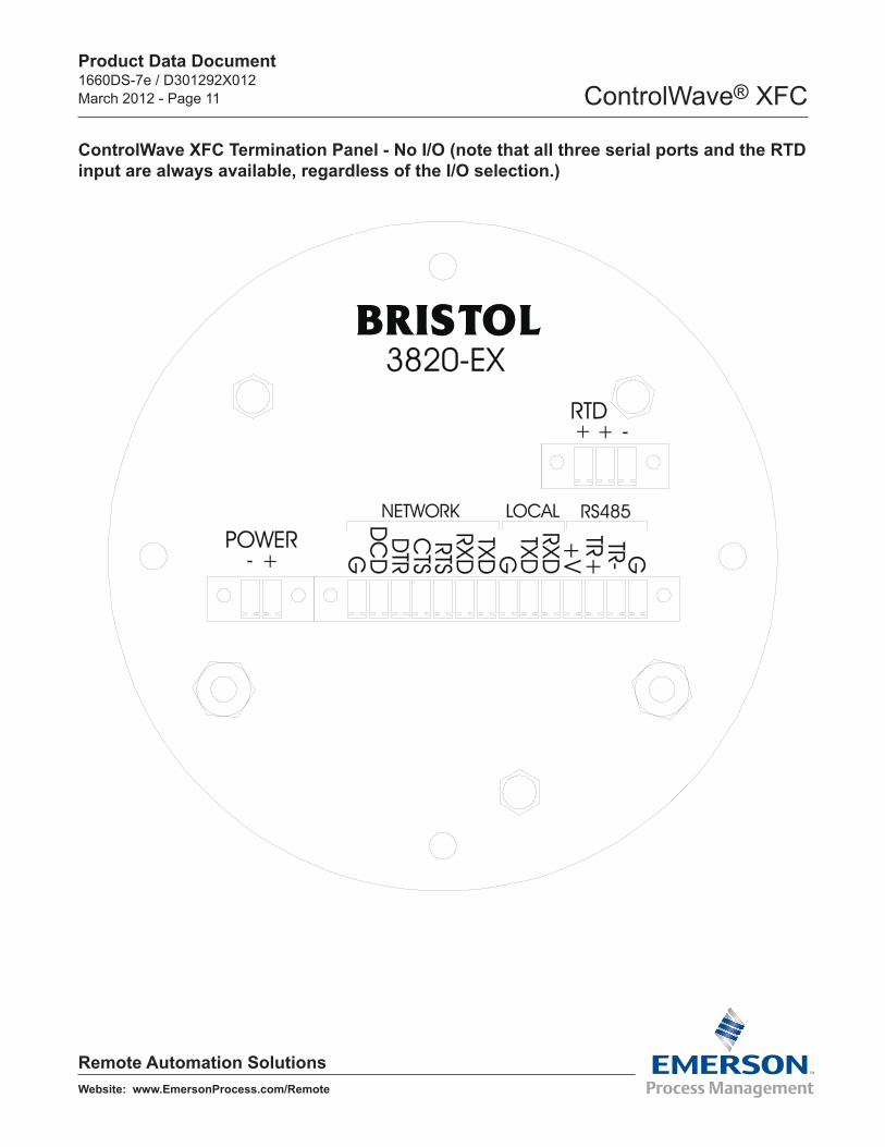
ControlWave XFC Termination Panel - No I/O (note that all three serial ports and the RTD input are always available, regardless of the I/O selection.)
Product Data Document1660DS-7e / D301292X012March 2012 - Page 12 ControlWave® XFC
Remote Automation SolutionsWebsite: www.EmersonProcess.com/Remote
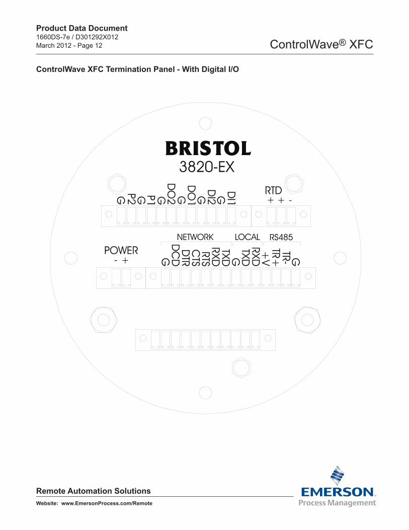
ControlWave XFC Termination Panel - With Digital I/O
Product Data Document1660DS-7e / D301292X012March 2012 - Page 13 ControlWave® XFC
Remote Automation SolutionsWebsite: www.EmersonProcess.com/Remote
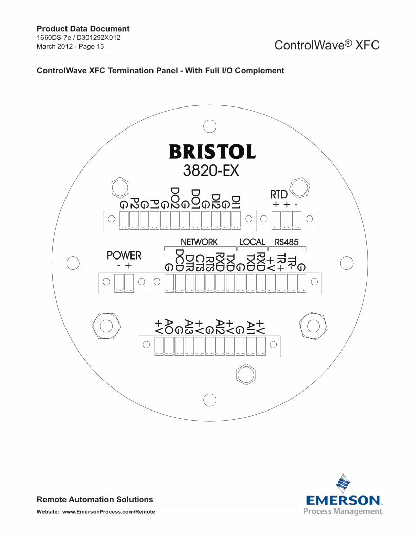
ControlWave XFC Termination Panel - With Full I/O Complement
Product Data Document1660DS-7e / D301292X012March 2012 - Page 14 ControlWave® XFC
Remote Automation SolutionsWebsite: www.EmersonProcess.com/Remote
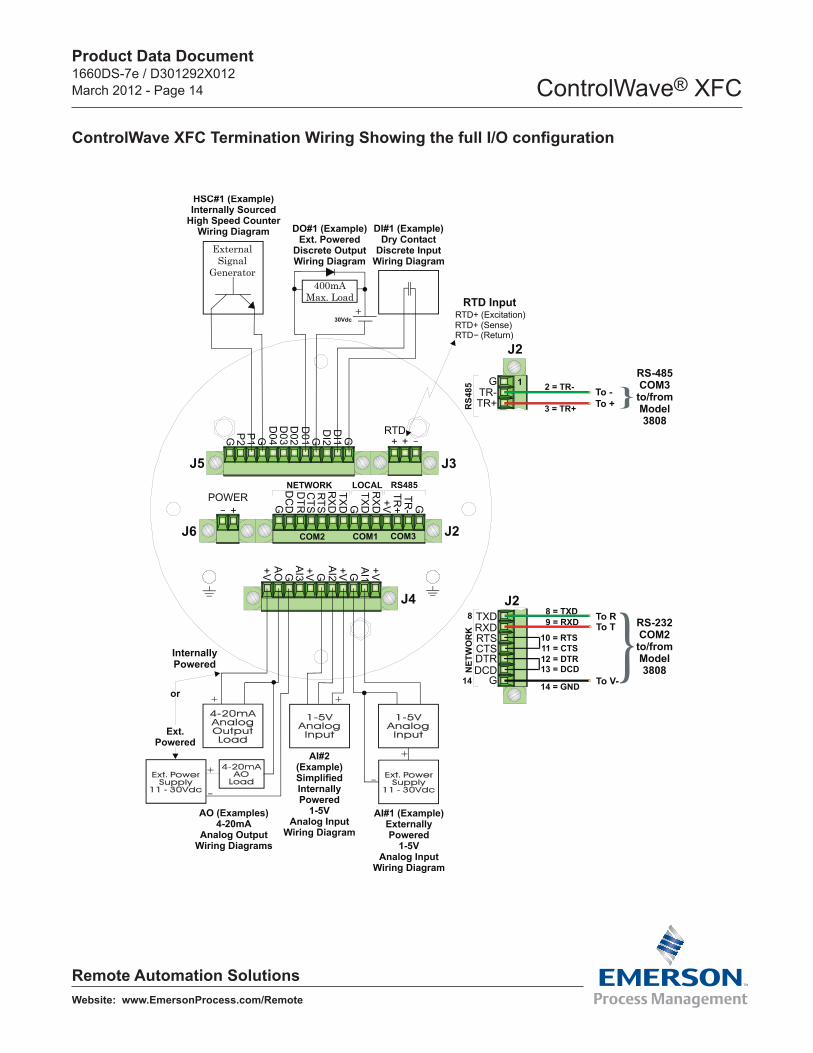
ControlWave XFC Termination Wiring Showing the full I/O configuration
Product Data Document1660DS-7e / D301292X012March 2012 - Page 15 ControlWave® XFC
Remote Automation SolutionsWebsite: www.EmersonProcess.com/Remote
Dimensions
Product Data Document1660DS-7e / D301292X012March 2012 - Page 16 ControlWave® XFC
Remote Automation SolutionsWebsite: www.EmersonProcess.com/Remote
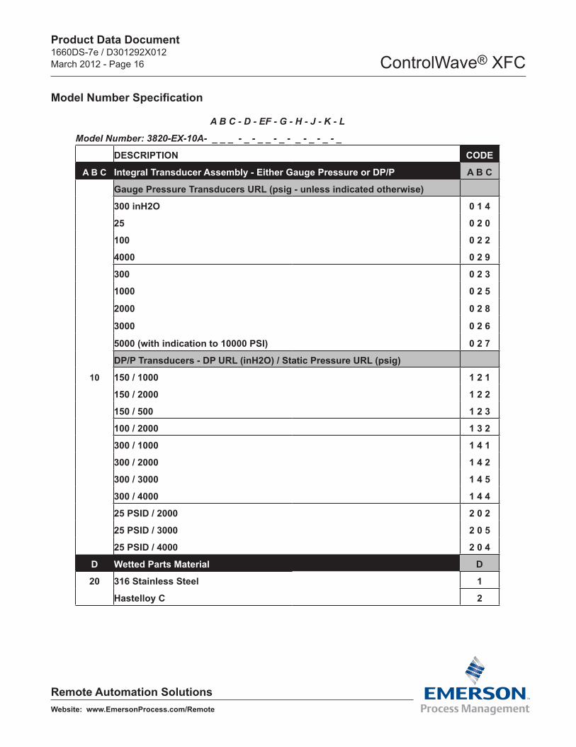
A B C - D - EF - G - H - J - K - L
Model Number: 3820-EX-10A- _ _ _ - _ - _ _ - _ - _ - _ - _ - _
DESCRIPTION CODE
A B C Integral Transducer Assembly - Either Gauge Pressure or DP/P A B C
Gauge Pressure Transducers URL (psig - unless indicated otherwise)
300 inH2O 0 1 4
25 0 2 0
100 0 2 2
4000 0 2 9
300 0 2 3
1000 0 2 5
2000 0 2 8
3000 0 2 6
5000 (with indication to 10000 PSI) 0 2 7
DP/P Transducers - DP URL (inH2O) / Static Pressure URL (psig)
10 150 / 1000 1 2 1
150 / 2000 1 2 2
150 / 500 1 2 3
100 / 2000 1 3 2
300 / 1000 1 4 1
300 / 2000 1 4 2
300 / 3000 1 4 5
300 / 4000 1 4 4
25 PSID / 2000 2 0 2
25 PSID / 3000 2 0 5
25 PSID / 4000 2 0 4
D Wetted Parts Material D
20 316 Stainless Steel 1
Hastelloy C 2
Model Number Specification
Product Data Document1660DS-7e / D301292X012March 2012 - Page 17 ControlWave® XFC
Remote Automation SolutionsWebsite: www.EmersonProcess.com/Remote
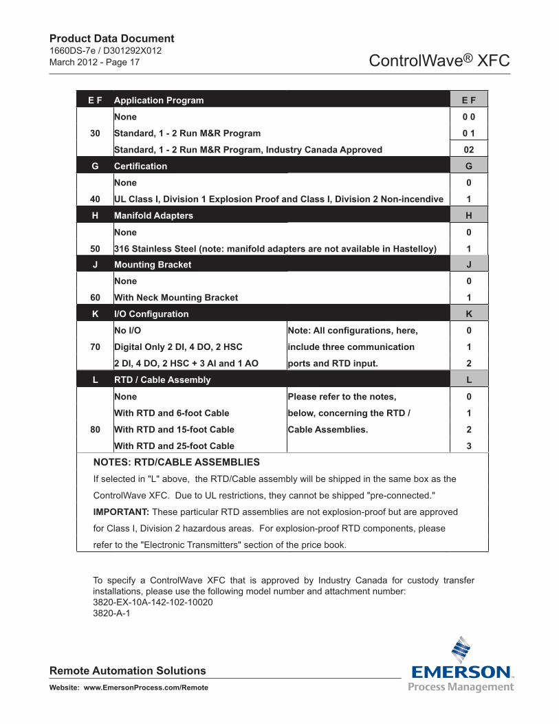
E F Application Program E F
None 0 0
30 Standard, 1 - 2 Run M&R Program 0 1
Standard, 1 - 2 Run M&R Program, Industry Canada Approved 02
G Certification G
None 0
40 UL Class I, Division 1 Explosion Proof and Class I, Division 2 Non-incendive 1
H Manifold Adapters H
None 0
50 316 Stainless Steel (note: manifold adapters are not available in Hastelloy) 1J Mounting Bracket J
None 0
60 With Neck Mounting Bracket 1
K I/O Configuration K
No I/O Note: All configurations, here, 0
70 Digital Only 2 DI, 4 DO, 2 HSC include three communication 1
2 DI, 4 DO, 2 HSC + 3 AI and 1 AO ports and RTD input. 2
L RTD / Cable Assembly L
None Please refer to the notes, 0
With RTD and 6-foot Cable below, concerning the RTD / 1
80 With RTD and 15-foot Cable Cable Assemblies. 2
With RTD and 25-foot Cable 3
NOTES: RTD/CABLE ASSEMBLIESIf selected in "L" above, the RTD/Cable assembly will be shipped in the same box as the
ControlWave XFC. Due to UL restrictions, they cannot be shipped "pre-connected."
IMPORTANT: These particular RTD assemblies are not explosion-proof but are approved
for Class I, Division 2 hazardous areas. For explosion-proof RTD components, please
refer to the "Electronic Transmitters" section of the price book.
To specify a ControlWave XFC that is approved by Industry Canada for custody transfer installations, please use the following model number and attachment number:3820-EX-10A-142-102-100203820-A-1
Product Data Document1660DS-7e / D301292X012March 2012 - Page 18 ControlWave® XFC
Remote Automation SolutionsWebsite: www.EmersonProcess.com/Remote
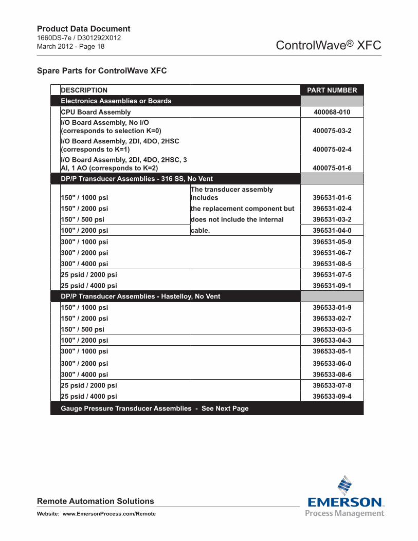
DESCRIPTION PART NUMBERElectronics Assemblies or BoardsCPU Board Assembly 400068-010I/O Board Assembly, No I/O (corresponds to selection K=0) 400075-03-2I/O Board Assembly, 2DI, 4DO, 2HSC (corresponds to K=1) 400075-02-4I/O Board Assembly, 2DI, 4DO, 2HSC, 3 AI, 1 AO (corresponds to K=2) 400075-01-6DP/P Transducer Assemblies - 316 SS, No Vent
150" / 1000 psiThe transducer assembly includes 396531-01-6
150" / 2000 psi the replacement component but 396531-02-4150" / 500 psi does not include the internal 396531-03-2100" / 2000 psi cable. 396531-04-0300" / 1000 psi 396531-05-9300" / 2000 psi 396531-06-7300" / 4000 psi 396531-08-525 psid / 2000 psi 396531-07-525 psid / 4000 psi 396531-09-1DP/P Transducer Assemblies - Hastelloy, No Vent150" / 1000 psi 396533-01-9150" / 2000 psi 396533-02-7150" / 500 psi 396533-03-5100" / 2000 psi 396533-04-3300" / 1000 psi 396533-05-1
300" / 2000 psi 396533-06-0300" / 4000 psi 396533-08-625 psid / 2000 psi 396533-07-825 psid / 4000 psi 396533-09-4
Gauge Pressure Transducer Assemblies - See Next Page
Spare Parts for ControlWave XFC
Product Data Document1660DS-7e / D301292X012March 2012 - Page 19 ControlWave® XFC
Remote Automation Solutions
Headquarters: Emerson Process Management Remote Automation Solutions 6005 Rogerdale Road Houston, TX 77072 U.S.A. T +1 281 879 2699 | F +1 281 988 4445 www.EmersonProcess.com/Remote
Europe: Emerson Process Management Remote Automation Solutions Emerson House Kirkhill Drive Kirkhill Industrial Estate Aberdeen UK AB21 OEU T +44 1224 215700 | F +44 1224 215799 www.EmersonProcess.com/Remote
North American/Latin America: Emerson Process Management Remote Automation Solutions 6005 Rogerdale Road Houston TX USA 77072 T +1 281 879 2699 | F +1 281 988 4445 www.EmersonProcess.com/Remote
Middle East/Africa: Emerson Process Management Remote Automation Solutions Emerson FZE P.O. Box 17033 Jebel Ali Free Zone – South 2 Dubai U.A.E. T +971 4 8118100 | F +971 4 8865465 www.EmersonProcess.com/Remote
Asia-Pacific: Emerson Process Management Remote Automation Solutions 1 Pandan Crescent Singapore 128461 T +65 6777 8211| F +65 6777 0947 www.EmersonProcess.com/Remote
© 2007-2012 Remote Automation Solutions, a business unit of Emerson Process Management. All rights reserved.
Remote Automation Solutions, a business unit of Emerson Process Management, shall not be liable for technical or editorial errors in this manual or omissions from this manual. REMOTE AUTOMATION SOLUTIONS MAKES NO WARRANTIES, EXPRESSED OR IMPLIED, INCLUDING THE IMPLIED WARRANTIES OF MERCHANTABILITY AND FITNESS FOR A PARTICULAR PURPOSE WITH RESPECT TO THIS MANUAL AND, IN NO EVENT SHALL REMOTE AUTOMATION SOLUTIONS BE LIABLE FOR ANY INCIDENTAL, PUNITIVE, SPECIAL OR CONSEQUENTIAL DAMAGES INCLUD-ING, BUT NOT LIMITED TO, LOSS OF PRODUCTION, LOSS OF PROFITS, LOSS OF REVENUE OR USE AND COSTS INCURRED INCLUDING WITHOUT LIMITATION FOR CAPITAL, FUEL AND POWER, AND CLAIMS OF THIRD PARTIES.
Bristol, Inc., Bristol Canada, BBI SA de CV and Emerson Process Management Ltd, Remote Automa-tion Solutions (UK), are wholly owned subsidiaries of Emerson Electric Co. doing business as Remote Automation Solutions, a business unit of Emerson Process Management. FloBoss, ROCLINK, Bristol, Bristol Babcock, ControlWave, TeleFlow, Helicoid, OpenEnterprise, and METCO are trademarks of Remote Automation Solutions. AMS, PlantWeb and the PlantWeb logo are marks of Emerson Electric Co. The Emerson logo is a trademark and service mark of the Emerson Electric Co. All other marks are property of their respective owners.
The contents of this publication are presented for informational purposes only. While every effort has been made to ensure informational accuracy, they are not to be construed as warranties or guaran-tees, express or implied, regarding the products or services described herein or their use or applicabil-ity. Remote Automation Solutions reserves the right to modify or improve the designs or specifications of such products at any time without notice. All sales are governed by Remote Automation Solutions’ terms and conditions which are available upon request. Remote Automation Solutions does not as-sume responsibility for the selection, use or maintenance of any product. Responsibility for proper selection, use and maintenance of any Remote Automation Solutions product remains solely with the purchaser and end-user.
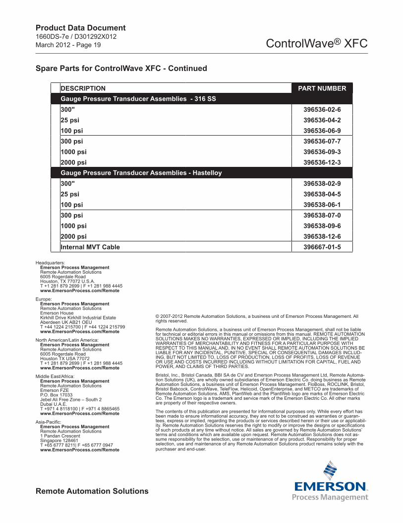
DESCRIPTION PART NUMBERGauge Pressure Transducer Assemblies - 316 SS300" 396536-02-625 psi 396536-04-2100 psi 396536-06-9300 psi 396536-07-71000 psi 396536-09-32000 psi 396536-12-3Gauge Pressure Transducer Assemblies - Hastelloy300" 396538-02-925 psi 396538-04-5100 psi 396538-06-1300 psi 396538-07-01000 psi 396538-09-62000 psi 396538-12-6Internal MVT Cable 396667-01-5
Spare Parts for ControlWave XFC - Continued