Embed Size (px)
Citation preview

ControlSpace® SERIAL CONTROL PROTOCOL v5.2
31/01/18

ControlSpace® SERIAL CONTROL PROTOCOL
PRO.BOSE.COM 2 OF 68
Table of Contents 1 About 2 Connection 3 Command Format 4 System Commands
4.1 Set/Get Parameter Set (SS, GS) 4.2 Set/Get Group Master Level (SG, GG) 4.3 Set Group Volume Increment/Decrement (SH) 4.4 Set/Get Group Master Mute (SN/GN) 4.5 Set/Get Room Combine (SRC/GRC) 4.6 Set/Get Parameter Set Lists (SA/GA)
5 Device Commands 5.1 Set/Get Input/Output Volume (SV, GV) 5.2 Set Volume Increment/Decrement (SI) 5.3 Set/Get Mute (SM, GM) 5.4 Get Signal Level (GL) 5.5 Set/Get IP Address (IP) 5.6 Network Parameters (NP) 5.7 Reset/Reboot Device (RESET) 5.8 Set/Get Standby Status (SY,GY) [PowerMatch Only] 5.9 Get Configuration (GC) [PowerMatch Only]
5.10 Set/Get Fault Status (SF, GF) [PowerMatch Only] 5.11 Clear Fault/Alarms (CF) [PowerMatch Only] 5.12 Set/Get Alarm Reporting/Status (SR, GR) [PowerMatch Only] 5.13 Get/Clear Alarm History/Log (GH, CH) [PowerMatch Only]
6 Module Commands Set/Get Module Parameter (SA,GA)/Invoke Module Action (MA)
6.1 ESP Module Indices 6.1.1 INPUT Module 6.1.2 OUTPUT Module 6.1.3 ESPLink Module 6.1.4 AMPLink Module 6.1.5 DANTE I/O Modules 6.1.6 COBRANET I/O Modules 6.1.7 SURROUND INPUT Module 6.1.8 PSTN INPUT Module 6.1.9 PSTN OUTPUT Module 6.1.10 VoIP INPUT Module 6.1.11 VoIP OUTPUT Module 6.1.12 USB INPUT Module 6.1.13 USB OUTPUT Module 6.1.14 ACOUSTIC ECHO CANCELLER Module 6.1.15 AGC Module (Enhanced) 6.1.16 AGC Module (Legacy) 6.1.17 ARRAY EQ Module 6.1.18 AUTOMATIC MIC MIXER-GAIN SHARING Module 6.1.19 AUTOMATIC MIC MIXER-GATED Module (Legacy) 6.1.20 AUTOMATIC MIC MIXER-GATED Module (Enhanced) 6.1.21 COMPRESSOR/LIMITER Module 6.1.22 CONFERENCE ROOM ROUTER Module 6.1.23 CROSSOVER Module 6.1.24 DELAY Module 6.1.25 DUCKER Module 6.1.26 GAIN Module 6.1.27 GATE Module 6.1.28 GPO Module 6.1.29 1/3 OCTAVE GRAPHIC EQ Module 6.1.30 LOGIC INPUT Module 6.1.31 LOGIC OUTPUT Module 6.1.32 LOGIC PROCESSING Module
6.1.32.1. TOGGLE/FF Gate 6.1.32.2. PULSE Gate 6.1.32.3. DEBOUNCE Gate
6.1.33 MATRIX MIXER Module 6.1.34 PARAMETRIC EQ Module

ControlSpace® SERIAL CONTROL PROTOCOL
PRO.BOSE.COM 3 OF 68
6.1.35 PEAK/RMS LIMITER Module 6.1.36 ROUTER Module 6.1.37 SIGNAL GENERATOR Modules 6.1.38 SOURCE SELECTOR Module 6.1.39 SPEAKER PARAMETRIC EQ Module 6.1.40 STANDARD MIXER Module 6.1.41 TONE CONTROL EQ Module
6.2 PowerMatch Module Indices 6.2.1 INPUT Module 6.2.2 SIGNAL GENERATOR Module 6.2.3 INPUT PARAMETRIC EQ Module 6.2.4 ARRAY EQ Module 6.2.5 MATRIX MIXER Module 6.2.6 BAND PASS Module 6.2.7 SPEAKER PARAMETRIC EQ Module 6.2.8 LIMITER Module 6.2.9 DELAY Module 6.2.10 AMP OUTPUT Module
7 Endpoint Commands
7.1 Identify/Find Unit (ID/FU) 7.2 Input Gain (IG) 7.3 Input Source (IS) 7.4 Phantom Power (PP) 7.5 Output Gain (OG) 7.6 Read Signal Level (RSL) 7.7 Read/Write Logic Output (RLO/WLO) 7.8 Read Logic Input (RLI) 7.9 Set Logic Event (EVNT)
7.10 Set Event Notification IP Address (SASIP) 7.11 Load/Save Preset (LOAD/SAVE) 7.12 Query Audio Settings (QUERY) 7.13 Restore Factory Defaults (DEFAULTS) 7.14 Query Firmware Version (VERSION)
Appendix A: PSTN Country Codes
1 About This ControlSpace® Serial Control Protocol document covers the following products:
ControlSpace EX-1280C conference processor ControlSpace ESP-880, ESP-1240, ESP-4120, ESP-1600 processors ControlSpace ESP-00 Series II, ESP-00, ESP-88 processors PowerMatch PM8500N, PM8250N, PM4500N, PM4250N amplifiers ControlSpace WP,EP and EX Dante™ Endpoint audio interfaces
This protocol provides a communication mechanism for Bose ControlSpace and PowerMatch products to interface with third-party control systems such as; AMX, Crestron, Extron, or any other controller capable of following this protocol. The purpose of this document is to provide programmers and integrators the necessary details on the available commands, their behaviour and syntax. Note: Whenever this document references the ESP-00 it applies equally to the current ESP-00 II, and to the legacy ESP-00 and ESP-88 processors.

ControlSpace® SERIAL CONTROL PROTOCOL
PRO.BOSE.COM 4 OF 68
2 Connection Using the RS-232 Serial Port (ESP and EX only)
When using RS-232, a 3-wire connection is sufficient to communicate with the ESP or EX (use of the CTS/RTS pins on the ESP is optional). ESP Processors use a 9-way D connector configured as DTE, so a crossover (or null-modem) cable will be required to connect directly to a PC, whereas the EX-1280C uses a miniature Phoenix connector and can be wired as required. The default communication settings are shown below. If required these settings can be changed via ControlSpace Designer™ software.
Using Serial-over-Ethernet (ESP,EX and PowerMatch) ESP, EX and (networked) PowerMatch products can be controlled via serial commands sent over Ethernet using a TCP/IP connection. Communication is via the same physical Ethernet connection used for the ControlSpace Designer software but a dedicated port number (10055) is provided for third-party control allowing them to operate simultaneously. Note: The third-party control connection will be closed when going on-line with ControlSpace Designer software to allow the new design to be loaded. The control connection can be re-established once on-line. Most control systems can do this automatically. ESP, EX and (networked) PowerMatch products can support up to eight simultaneous serial-over-Ethernet connections (in addition to the physical RS232 serial port on ESP/EX). These connections are shared with any instances of ControlSpace Remote which use the same communication method. Once eight connections have been established, additional requests will be refused until one of the existing connections has been closed. Serial output and asynchronous feedback is sent to all active connections (including the physical RS232 port on ESP/EX) and Serial input will monitor all active connections for the specified strings. In contrast, responses to query commands are returned only to the connection that initiated the query. The ESP-00 and PowerMatch products use a fixed port number of ‘10055’ for third-party control connections. 1U ESPs (880/1240/4120/1600) and EX devices also use the same port by default, but allow the port to be changed or disabled via the device properties in the ControlSpace Designer software if required. It’s important to note that ESP, EX and PowerMatch products only act as Server for serial-over-Ethernet connections, the connection must be initiated by the Client device. Using Serial-over-Ethernet (WP, EP and EX Endpoints) Endpoints can also be controlled via serial commands sent over Ethernet, but these use UDP packets and a fixed port number of “49494”. Where endpoints are paired with EX processors, any settings sent to the endpoint directly can be overridden by those programmed in the processor. When paired, changes should only be made via ControlSpace Designer software while online with the EX processor.
ESP-00 ESP-880/1240/4120/1600/EX-1280C
Baud 38,400 115,200 Data bits 8 8 Parity None None Stop bits 1 1
RS-232 Panel Connector Pinout (DTE)

ControlSpace® SERIAL CONTROL PROTOCOL
PRO.BOSE.COM 5 OF 68
For reference, a list of the ports used by ControlSpace devices is provided below:
ESP, EX and PM Serial-over-Ethernet 10055
ControlSpace Designer software 10001,10002
Scan/Discovery 9010
Firmware updates 9008, 9009
Inter-device communication 2005, 2006, 2007
Endpoint UDP Control 49494
Using ‘Hyperterminal’ configured for TCP/IP (as shown below) is a convenient way to test these commands.
Note: HyperTerminal is no longer bundled with newer versions of Microsoft Windows® operating systems. Freeware or open-source solutions such as ClearTerminal, RealTerm or PuTTy are available online and can be used to test commands as well.

ControlSpace® SERIAL CONTROL PROTOCOL
PRO.BOSE.COM 6 OF 68
3 Command Format All commands and responses are sent using ASCII characters, terminated with a <CR> (carriage return, ASCII 0x0D). There is no time limit between characters of a command so it is possible to enter commands using a “dumb terminal”. The available commands are divided into the following categories per their scope.
System Commands (Parameter Sets, Groups ..) Device Commands (Inputs, Outputs, Set IP address, Get alarm status ..) Module Commands (Signal processing parameters ..) Endpoint Commands (Input gain, Phantom power, Logic I/O ..)
System and Device Commands Numerical values for System and Device Commands are entered using hexadecimal ASCII. For example, 16 (decimal) is entered as 10 (hex) and 34 (decimal) is entered as 22 (hex).
> Command should be capital letters > A space after the command is optional (SS 10 or SS10 are both acceptable) > A comma "," is used as the separator > Hexadecimal values do not require a suffix ("A3h" not allowed – should be "A3") > Hexadecimal values can be sent in upper or lower case (SS A or SS a are both acceptable, but responses are
always in lower case) > All commands are terminated with a <CR> (Carriage Return – ASCII 0x0D) > No acknowledgement is sent. Following a ‘Set’ command with a ‘Get’ is a convenient method for confirming the
command was successful. Module Commands: Numerical values for Module Commands are entered as simple ASCII text. For example, -28dB is entered simply as “-28”
> Command should be capital letters > A space after the command is optional (SA “xx” or SA“xx” are both acceptable) > Module name must be unique and should always be enclosed in quotes (“Name”) > Command may have 1 ,2 or 3 Indices separated by “>” (ASCII 0x3E) > Set commands and Get responses always end with “=” (ASCII 0x3D) followed by the parameter value > Numerical values are entered as simple ASCII text without the units (e.g. -28dB is simply entered as “-28”) > Multiple commands sent on a single line are separated by a semi-colon (ASCII 0x3B) > All commands are terminated with a <CR> (Carriage Return – ASCII 0x0D) > Devices respond with ‘ACK’ (ASCII 0x06) if successful or ‘NAK nn’ if unsuccessful where nn is a 2-digit error code.
Endpoint Commands: Numerical values for Module Commands are entered as basic ASCII text. For example, -15dB would be entered as “-15.0”
> Commands should be capital letters > Command may have 1 or 2 parameters separated by <SPACE> (ASCII 0x20) > Numerical values are entered as simple ASCII text without the units (e.g. -15dB is simply entered as “-15.0”) > All commands are terminated with a <CR> (Carriage Return – ASCII 0x0D)

ControlSpace® SERIAL CONTROL PROTOCOL
PRO.BOSE.COM 7 OF 68
> Devices respond with “ACK” and an echo of received command if successful or “NACK” if unsuccessful. Note that these are text strings and not the ASCII <ACK> and <NAK> characters used in the Module Commands.
4 System Commands System commands are used to invoke changes across multiple devices simultaneously and use constructs programmed via ControlSpace Designer software (such as Parameter Sets and Groups). Commands issued to the designated ‘RTC/Main’ device will be echoed to all other devices on the network (assuming they are correctly connected to the same network). Otherwise, commands should be issued to one of the devices involved in the construct being controlled (e.g. if a Group spans two ESPs, then the Group command should only be issued to one of those two devices, not to others). System commands use hexadecimal notation for numerical values and only ‘Get’ commands generate a response. Following a ‘Set’ command with a ‘Get’ is a useful way to confirm command success.
4.1 Set/Get Parameter Set (SS, GS) 4.2 Set/Get Group Volume Master Level (SG, GG) 4.3 Set Group Volume Increment/Decrement (SH) 4.4 Set/Get Group Volume Master Mute (SN, GN) 4.5 Set/Get Room Combine (SRC, GRC) 4.6 Set/Get Parameter Set Lists (GA, SA)
4.1 Set/Get Parameter Set (SS, GS)
To recall or invoke Parameter Set n: SS n <CR> where n is the Parameter Set number, 1 - FFh (1-255 decimal)
To query for the last invoked Parameter Set: GS<CR>
Response: S n<CR> where n = 0 – FF (n = 0 if no Parameter Set recalled, e.g. after power-up)
EXAMPLES: SS b<CR> Recall Parameter Set 11 (hex = b) GS<CR> Query for last invoked Parameter Set S 5<CR> Response indicating Parameter Set 5 was invoked last
ControlSpace® SERIAL CONTROL PROTOCOL
PRO.BOSE.COM 8 OF 68
4.2 Set/Get Group Master Level (SG, GG) Groups of ESP inputs, outputs or gain blocks have a range of -60dB to +12dB, whereas PowerMatch Amplifier outputs do not have gain and therefore have a maximum level of 0dB (78h). To set the master level of Group n to level l :
SG n,l <CR> where n is the Group number, 1 – 40h (1-64 decimal) l is the level, 0h(-60dB) to 90h(+12dB) in 0.5dB steps (0-144 dec)
or PM, 0h(-60dB) to 78h(0dB) in 0.5dB steps (0-120 dec)
To query the level of Group n GG n <CR> where n is the Group number, 1 – 40h (1-64 decimal)
Response: GG n,l where n,l are the same as above.
EXAMPLES: SG 2,78<CR> Set level for Group 2 to 0dB GG 2<CR> Query the level for Group 2 GG 2,80<CR> Response indicating Group 2 is set to 1dB
4.3 Set Group Level Increment/Decrement (SH)
To increment (or decrement) the master level of Group n by x number of 0.5dB steps: SH n,d,x<CR> where n is the Group number, 1 – 40h (1-64 decimal)
d is the direction, 1=up or 0=down x is the number of 0.5dB steps in hexadecimal (e.g. 5dB = A)
EXAMPLES:
SH 2,1,6<CR> Increase the level of Group 2 by 3dB SH 7,0,3<CR> Decrease the level of Group 7 by 1.5dB
4.4 Set/Get Group Master Mute (SN, GN)
To set or change the Mute state for Group n: SN n,m<CR> where n is the Group number, 1 – 40h (1-64 decimal)
m is the state, M = Mute, U = Un-mute, T = Toggle mute state
To query the Mute state of Group n: GN n <CR> where n is the Group number, 1 – 40h (1-64 decimal)
Response: GN n,m where n,m are the same as above.
EXAMPLES: SN 4,M<CR> Engage Mute for Group 4

ControlSpace® SERIAL CONTROL PROTOCOL
PRO.BOSE.COM 9 OF 68
GN 4<CR> Query the Mute status for Group 4 GN 4,M<CR> Response indicating Group 4 is Muted
4.5 Set/Get Room Combine (SRC, GRC) [EX Only]
Room Combine Groups allow several rooms to be organized and managed together using Conference Room Router modules. Once the Conference Room Router module for each of the rooms has been added to a Room Combine Group it becomes possible to join or split rooms in different combinations, routing the audio between them and linking their master volume controls together. This is typically used for adaptable conference rooms where dividing partitions can be added to split rooms, or removed to combine several smaller rooms into one large room. These commands are used to join or split pairs of rooms within a given Room Combine Group, much like the physical partitions. Rooms can be referenced by their number or name. Both of which are defined in the Room Combine Group configuration panel. To join two rooms together using room numbers:
SRC n,a,b,s <CR> where n is the Room Combine Group number, 1-6 a,b are the room numbers, 1-6 s is the state, J = Join and S = Split
To join two rooms together using room names: SRC "N","A","B",s <CR> where N is the Room Combine Group name
A,B are the room names s is the state, J = Join and S = Split
To query whether two rooms are joined using room numbers: GRC n,a,b <CR> where n is the Room Combine Group number, 1-6
a,b are the room numbers, 1-6 Response: GRC n,a,b,s <CR> where n is the Room Combine Group number, 1-6
a,b are the room numbers, 1-6 s is the state, J = Join and S = Split
To query whether two rooms are joined using room names: GRC n,"A","B" <CR> where n is the Room Combine Group number, 1-6
A,B are the room names Response: GRC n,”A”,”B”,s <CR> where n is the Room Combine Group number, 1-6
A,B are the room names s is the state, J = Join and S = Split
To query which rooms are currently joined: GRC n <CR> where n is the Room Combine Group number (or name) Response: GRC n,[a,b][c,d,f] <CR> where n is the Room Combine Group number
a-f are the room numbers and the brackets “[]” indicate which rooms are joined
EXAMPLES: SRC 2,"Victory","Trafalgar",J<CR> Join rooms named “Victory” and “Trafalgar” from RC Group 2 SRC 1,2,4,S<CR> Split rooms 2 and 4 in Room Combine Group 1 GRC "Ground Floor"<CR> Query for currently joined rooms in the “Ground Floor” RC Group

ControlSpace® SERIAL CONTROL PROTOCOL
PRO.BOSE.COM 10 OF 68
GRC "Ground Floor",[2,4,5][1,3]<CR> Response indicating rooms 2,4 and 5 are joined, and rooms 1 and 3 are joined
4.6 Set/Get Parameter Set Lists (SA, GA) Parameter Set Lists are logical groupings of Parameter Sets. These commands are used to query for or change the currently selected Parameter Set in a Parameter Set List. To query for the current selection of a Parameter Set List:
GA "A">1 <CR> where A is the Parameter Set List’s name or GA "A">2 <CR> where A is the Parameter Set List’s name Response: GA “A”>1=n <CR> where A is the Parameter Set List’s name where n is the index of the current selection or GA “A”>2=n <CR> where A is the Parameter Set List’s name where n is the index of the current selection or <NAK>01 A not recognized as valid Parameter Set List name or <NAK>02 number after ‘>’ not 1 or 2
To change the current selection of a Parameter Set List:
SA "A">1=n <CR> where A is the Parameter Set List’s name n is index of the Parameter Set in the list to select
or SA "A">2=n <CR> where A is the Parameter Set List’s name
n is index of the Parameter Set in the list to select Response: <ACK> Selection set to nearest possible selection
(1 if n = 0, max selection if n greater than max selection, otherwise n)
or <NAK>01 A not recognized as valid Parameter Set List name or <NAK>02 number between ‘>’ and ‘=’ not 1 or 2 or <NAK>03 n set to a negative value
5 Device Commands Device commands should be issued directly to the relevant ControlSpace device and will invoke changes locally within that device. Device commands use hexadecimal notation for numerical values and generally only ‘Get’ commands generate a response. Following a ‘Set’ command with a ‘Get’ is a useful way to confirm successful execution.
ControlSpace® SERIAL CONTROL PROTOCOL
PRO.BOSE.COM 11 OF 68
5.1 Set/Get Input/Output Volume (SV, GV) 5.2 Set Volume Increment/Decrement (SI) 5.3 Set/Get Input/Output Mute (SM, GM) 5.4 Get Signal Level (GL) 5.5 Set/Get IP Address (IP) 5.6 Network Parameters (NP) 5.7 Reset/Reboot Device (RESET) 5.8 Set/Get Standby Status (SY, GY) [PowerMatch Only] 5.9 Get Configuration (GC) [PowerMatch Only]
5.10 Set/Get Fault Status (SF, GF) [PowerMatch Only] 5.11 Clear Fault/Alarms (CF) [PowerMatch Only] 5.12 Set/Get Alarm Reporting/Status (SR, GR) [PowerMatch Only] 5.13 Get/Clear Alarm History/Log (GH, CH) [PowerMatch Only]
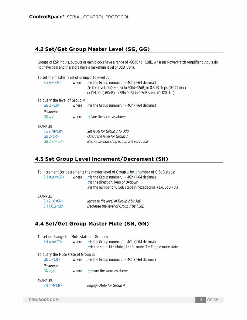
The Volume (SV, GV, SI) and Mute (SM, GM) commands allow control of input/output levels and mutes directly, referenced by a slot and channel number per the physical architecture of the device, rather than by Module name. Whilst these commands are still currently supported it is recommended that Module commands (SA, GA) be used to control the input and output modules for new projects.
The ESP-00 has 8 audio card slots and each card can support up to 8 channels, although many cards only have 4 channels and do not use channels 5-8. These commands are not supported on Surround decoder, Dante and CobraNet cards.
ESP-880/1240/4120/1600, EX and PowerMatch devices have a fixed architecture but still allow channels to be referenced using the following pseudo ‘slot’ numbers:
Table 1 Note: For 8ch PowerMatch devices the Get Signal Level (GL) command only uses Slot 1 (for Inputs) and Slot 2 (for Outputs) for all 8 channels.
5.1 Set/Get Input/Output Volume (SV, GV)
Input and output volume levels are referenced by slot and channel numbers per the physical architecture of the device (refer to Table 1 at the start of this section). PowerMatch devices only support volume control of the outputs, not the inputs. Note: Set Volume commands will be ignored if the channel is muted.
Slot ESP-00 ESP-880 ESP-1240 ESP-4120 ESP-1600 EX-1280C PM8xxxN PM4xxxN 1
Flex
ible
In 1-4 In 1-4 In 1-4 In 1-4 Out 1-4 In A-D In A-D 2 Out 1-4 Out 1-4 Out 1-4 In 5-8 Out 5-8 Out 1-4 Out 1-4 3 In 5-8 In 5-8 Out 5-8 In 9-12 In 1-4 In E-H 4 Out 5-8 In 9-12 Out 9-12 In 13-16 In 5-8 Out 5-8 5 ESPLink ESPLink ESPLink ESPLink In 9-12 6 AmpLink 7 Dante 8 AEC 9 VoIP 10 USB 11 PSTN

ControlSpace® SERIAL CONTROL PROTOCOL
PRO.BOSE.COM 12 OF 68
To set the input/output volume of slot s, channel c, to level l :
SV s,c,l<CR> where s is the slot number (refer to Table 1 at the start of this section) c is the channel number, 1 – 8 (for ESP), 1 - 4 (for PM) l is the level, 0h(-60dB) to 90h(+12dB) in 0.5dB steps (0-144 dec) or PM 0h(-60dB) to 78h(0dB) in 0.5dB steps (0-120 dec)
To query the input/output level of slot s, channel c: GV s,c<CR> where s is the slot number, (refer to Table 1 at the start of this section)
c is the channel number, 1 – 8 (for ESP), 1 - 4 (for PM) Response: GV s,c,l where s,c,l are the same as above.
EXAMPLES: SV 1,3,50<CR> Set volume for slot 1, channel 3 to -20dB GV 2,1<CR> Query the volume level for slot 2, channel 1 GV 2,1,78<CR> Response indicating the level for slot 2 channel 1 is set to 0dB
5.2 Set Volume Increment/Decrement (SI)
Input and output volume levels are referenced by slot and channel numbers per the physical architecture of the device (refer to Table 1 at the start of this section). PowerMatch devices only support volume control of the outputs, not the inputs. Note: Set Volume Increment/Decrement commands will be ignored if the channel is muted. To increment (or decrement) the level of slot s, channel c:
SI s,c,d,x<CR> where s is the slot number, (refer to Table 1 at the start of this section) c is the channel number, 1 – 8 (for ESP), 1 - 4 (for PM) d is the direction, 1=up or 0=down x is the number of 0.5dB steps in hexadecimal (e.g. 5dB = A)
EXAMPLES:
SI 2,3,1,6<CR> Increase the level of slot 2, channel 3 by 3dB SI 4,1,0,3<CR> Decrease the level of slot 4, channel 1 by 1.5dB
5.3 Set/Get Input/Output Mute (SM, GM)
Input and output volume levels are referenced by slot and channel numbers per the physical architecture of the device (refer to Table 1 at the start of this section). PowerMatch devices only support volume control of the outputs, not the inputs. To set or change the Mute status for slot s, channel c:

ControlSpace® SERIAL CONTROL PROTOCOL
PRO.BOSE.COM 13 OF 68
SM s,c,m<CR> where s is the slot number (refer to Table 1 at the start of this section) c is the channel number, 1 – 8 (for ESP), 1 – 4 (for PM) m is the state, M = Mute, U = Un-mute, T = Toggle mute state
To query the Mute status for slot s, channel c: GM s,c<CR> where s is the slot number (refer to Table 1 at the start of this section)
c is the channel number, 1 – 8 (for ESP), 1 – 4 (for PM) Response: GM s,c,m where s,c,m are the same as above.
EXAMPLES: SM 2,1,M<CR> Engage Mute for slot 2, channel 1 GM 3,2<CR> Query the Mute status for slot 3, channel 2 GM 3,2,U<CR> Response indicating slot 3, channel 2 is un-muted
5.4 Get Signal Level (GL)
This command can be used to query the current signal levels for inputs or outputs on an ESP or PowerMatch device. The levels returned for inputs and ESP outputs are dBFS in hexadecimal format. To convert to dBu, first convert to decimal and then add 24dB for ESP-00 and 25dB for ESP-880/1240/ 4120/1600. For PM outputs the levels returned are dBV max in hexadecimal format. For a mono channel, Vmax (0dB/78h/120d) = 71V, and for a bridged/quad channel Vmax (0dB/78h/120d) = 141V. To query the current signal level for channels in slot s:
GL s<CR> where s is the slot number (refer to Table 1 at the start of this section) Response: GL s [1,2,3,4,5,6,7,8] s is the slot number (refer to Table 1 at the start of this section)
1-8 are the dBFS levels for each channel (ESP/PM input) or dBVmax for each channel (PM output) 0h(-60dB) to 78h(0dB) in 0.5dB steps (0-120 decimal) Note: 4 channel cards will only return 4 values.
EXAMPLES: GL 1<CR> Query signal levels for slot 1 GL 1 [78,1,40,64]<CR> Response indicating levels are 0,-59.5,-28,-10dBFS GL 2<CR> Query signal levels for PowerMatch output levels GL 2 [0,0,0,0,0,0,64,64]<CR> Response indicating ch7& 8 are at -10dBVmax
5.5 Set/Get IP Address (IP) The Set and Get IP address commands provide an alternative method for querying and changing the IP address of ControlSpace Devices when the Hardware Manager in ControlSpace Designer software is unavailable. This can be particularly useful when the network settings for an ESP (which does not have a front panel display) are unknown, but you do have access to the RS232 serial port.

ControlSpace® SERIAL CONTROL PROTOCOL
PRO.BOSE.COM 14 OF 68
To query the current IP address for the device: IP<CR> Response: IP xxx.xxx.xxx.xxx <CR>
To set or change the IP address for the device: IP xxx.xxx.xxx.xxx<CR>
EXAMPLES: IP<CR> Query the current IP address for the device IP 192.168.0.160<CR> Response indicating an IP address of 192.168.0.160 is set IP 192.168.1.160<CR> Command changing the IP address to 192.168.1.160 (after boot)
Note: When using the IP command to change IP address, the changes do not take effect until after the device has been re-booted.
5.7 Network Parameters (NP) The Network Parameter command allows additional network settings such as; Subnet Mask, Default Gateway and DHCP mode to be set or queried. There is also a command to return all network settings (including the IP address) to their factory default settings. This can be particularly useful when the network settings for an ESP (which does not have a front panel display) are unknown, but you do have access to the RS232 serial port. To query a specific network setting for the device:
NP p<CR> where p is the network parameter to query, T = Type (DHCP or Static, not available for ESP-00), M = Subnet Mask, G = Default Gateway
Response: NP p,v <CR> where p is the network parameter queried
v is the value, D = DHCP or S = Static IP for Type <or> xxx.xxx.xxx.xxx address for Subnet Mask and Default Gateway
To set a specific network setting for the device: NP p,v<CR> where p is the network parameter to set, T= Type (DHCP or Static),
M = Subnet Mask, G = Default Gateway v is the value, D = DHCP or S = Static IP for Type <or> xxx.xxx.xxx.xxx address for Subnet Mask and Default Gateway
To reset all network parameters for the device to factory defaults:
NP F<CR>
Note: Any changes to network parameters do not take effect until after the device has been re-booted, or restarted using the ‘RESET<CR>’ command.
EXAMPLES:
NP M<CR> Query the current Subnet Mask for the device NP M,255.255.255.0<CR> Response indicating a Subnet Mask of 255.255.255.0 NP M,255.255.255.128<CR> Command to change Mask to 255.255.255.128 (after reboot) NP G,192.168.0.2<CR> Command to change Gateway to 192.168.0.2 (after reboot) NP T<CR> Query the current networking mode for the device NP T,D<CR> Response indicating device is currently set to DHCP

ControlSpace® SERIAL CONTROL PROTOCOL
PRO.BOSE.COM 15 OF 68
NP T,S<CR> Command for device to change to static IP addresses NP F<CR> Command to reset network settings to factory defaults
Factory default network settings
Device Type IP Address Subnet Mask Default Gateway Type ESP-00/88 192.168.0.160 255.255.255.0 192.168.0.1 N/A ESP-880/4120/1240/1600 192.168.0.160 255.255.255.0 192.168.0.1 DHCP EX-1280C 192.168.0.160 255.255.255.0 192.168.0.1 DHCP PM8500N/PM8250N 192.168.0.80 255.255.255.0 192.168.0.1 DHCP PM4500N/PM4250N 192.168.0.40 255.255.255.0 192.168.0.1 DHCP
Note: For the EX processor, resetting all network parameters to their defaults applies to the control connection only. The VoIP settings remain unaffected.
5.8 Reset/Reboot Device (RESET)
The Reset command instructs a device to restart (the equivalent of power-cycling or rebooting). This can be useful when making IP address or Network Parameter changes remotely since the changes only take effect after the device has been rebooted. When connected via RS232, an ESP will send a “Ready” string once the boot process is completed, whereas serial-over-Ethernet connections will need to be re-established once sufficient time has elapsed. The time it takes for a device to boot varies depending on the device type and the installed cards.
To reset/reboot a device:
RESET<CR> Note: Just like when the device is rebooted manually, all the current settings in the device will be lost and the device will revert to its power-on (flashed) settings.
EXAMPLE:
RESET<CR> Request the device to restart/reboot.
5.9 Set/Get Standby Status (SY, GY) [PowerMatch Only] The Set and Get Standby Status commands allow the power state of an individual PowerMatch amplifier to be controlled remotely. Since entering or exiting standby is not immediate, adequate time should be allowed for the process to complete.

ControlSpace® SERIAL CONTROL PROTOCOL
PRO.BOSE.COM 16 OF 68
Alternatively, the power state can also be controlled via Parameter Set using the device’s ‘Standby’ property. This option allows multiple PowerMatch devices to be controlled together.
Note: This command is not supported on ESP devices To set or change the standby state for a PowerMatch amplifier:
SY s <CR> where s is the state, S = Standby, N = Normal To query the current standby state for the device:
GY<CR> Response: GY s <CR> where s is the state, S = Standby, N = Normal
EXAMPLES: SY S<CR> Put the PowerMatch device into standby mode GY<CR> Query the current standby state GY N<CR> Response indicating PowerMatch device is in Normal state (On)
5.10 Get Configuration (GC) [PowerMatch Only] The Get Configuration (GC) command returns the current output configuration of a PowerMatch amplifier. Knowledge of the output configuration can be useful when using the module (SA/GA) commands to change parameters. To query the current output configuration
GC<CR> Response: GC 1,2,3,4,5,6,7,8<CR> where 1-8 is the configured state for each channel of the Amplifier (1-4 for
PM4250N/PM4500N): IN= Independent (Mono), BL = Bridged (LoZ), B7 = Bridged (70v), B1 = Bridged (100v), PA = Parallel, QL = Quad (LoZ), Q7 = Quad (70v), Q1 = Quad (100v)
EXAMPLES: GC <CR> Query the current output configuration GC IN,IN,BL,BL,Q7,Q7,Q7,Q7<CR> Response indicating channels 1&2 are Independent, 3&4 are Bridged (Lo-Z) and
5-8 are in Quad (70v) mode.
5.11 Set/Get Fault Status (SF, GF) [PowerMatch Only] The Get Fault Status (GF) command queries the current state of the Fault Output on a PowerMatch amplifier. The Set Fault status (SF) command enables or disables unsolicited transmission of changes to the Fault Output state. The format of the unsolicited message is the same as the response to the Get Fault status (GF) command.

ControlSpace® SERIAL CONTROL PROTOCOL
PRO.BOSE.COM 17 OF 68
Note: The Set Fault status (SF) preference is not retained on power down and will default to ‘Off’ each time the amplifier is powered up. To set (enable or disable) unsolicited notification of Fault Output state changes:
SF n<CR> where n is the notification state, O = On, F = Off To query the current Fault status:
GF <CR> Response: GF f <CR> where f is the current Fault status, F= Fault, C = No Fault
EXAMPLES: SF O<CR> Enable unsolicited output of Fault Output state changes GF<CR> Query the current status of the Fault Output GF F<CR> Response indicating that the PowerMatch device is currently in a fault state.
5.12 Clear Fault/Alarms (CF) [PowerMatch Only] The Clear Fault/Alarms (CF) command clears any currently active alarm conditions, and resets the Fault Output on a PowerMatch device. Note that if any alarm or fault conditions are still present after the reset, the alarm status and Fault output will be automatically set again. To clear currently active alarm conditions/Fault output:
CF<CR> Response: <ACK><CR>
EXAMPLES:
CF<CR> Command to clear active alarms/reset fault state <ACK><CR> Response indicating action was successful
5.13 Set/Get Alarm Reporting/Status (SR, GR) [PowerMatch Only] The Get Alarm Reporting (GR) command queries the current alarm/fault status for a channel of a PowerMatch amplifier, whilst the Set Alarm Reporting (SR) command enables or disables unsolicited transmission of alarm and fault events when they occur. The format of the unsolicited message is the same as the response to the Get Alarm Status (GR) command.

ControlSpace® SERIAL CONTROL PROTOCOL
PRO.BOSE.COM 18 OF 68
Note: The Set Alarm Reporting (SR) preference is not retained on power down and will default to ‘Off’ each time the amplifier is powered up. To set (enable or disable) unsolicited notification of alarm/fault notifications:
SR n<CR> where n is the notification state, O = On, F = Off
Unsolicited notification format: GR c,s,t,x<CR> where c is the channel number, 1 – 8
(or 0 for non-channel specific alarms such as Digital Audio Loss or AC Mains Loss) s is the severity; W=Warning, F=Fault, S= System
t is the alarm type; N=No Alarm, O=Open, S=Short, A=ACLoss, D=Digital Audio Loss, I=I-Share Jumper Missing, L=Limiting, C=Clip (Input), P=Protection, Z = Other x is the condition; S=Set, C=Clear (not used for all alarms/faults)
To query the current alarm status for a single channel:
GR c<CR> where c is the channel number, 1 – 8 (1 – 4 for PM4500N/PM4250N) Response: GR c,s,t,<CR> where c is the channel number, 1 – 8 s is the severity; W= Warning, F=Fault, S= System, N=No Alarm
t is the alarm type; N=None, O=Open, S=Short, I=I-Share Jumper Missing, Z = Other
Note: If multiple alarms/faults exist for the same channel, the one with the highest severity will be returned. The transient nature of alarms such as limiting or clipping means they cannot be queried manually. To receive such alarms, turn on automatic notification. Only the first instance of limiting or clipping for a given channel is reported, so for continued monitoring alarms should be cleared after each notification.
EXAMPLES:
SR O<CR> Enable unsolicited notification of Alarm/Fault conditions GR 5,F,I,S<CR> Unsolicited notification that the I share jumper is missing for channels 5 & 6 GR 6,F,I,S<CR> GR 4<CR> Query the current alarm/fault status for channel 4 GR 4,F,S<CR> Response indicating that ch4 has a ‘SHORT’ fault condition
5.14 Get/Clear Alarm History/Log (GH, CH) [PowerMatch Only]
The Get Alarm History (GH) command requests a dump of the internal alarm history/log to the serial output, whilst the Clear Alarm History (CH) command causes the internal alarm log to be cleared.

ControlSpace® SERIAL CONTROL PROTOCOL
PRO.BOSE.COM 19 OF 68
Note: The alarm log is returned in a similar format to the front panel display or the alarm panel in ControlSpace Designer software. Actual time/date values will only be returned if there has been no loss in power since last connected to ControlSpace Designer software. Otherwise, relative values since last power-up will be returned. To query/request the alarm log:
GH<CR> Response: GH [Time, Date, Description<CR> Time, Date, Description<CR> …… Time, Date, Description]<CR
To clear the internal alarm history/log CH<CR> Response: <ACK><CR>
EXAMPLES: CH<CR> Request Alarm log be cleared <ACK><CR> Response indicating command was successful
6 Module Commands Module commands allow control of parameters for a specific signal processing module on a specific device.
Set/Get Module Parameter (SA, GA), Invoke Module Action (MA)
ControlSpace® SERIAL CONTROL PROTOCOL
PRO.BOSE.COM 20 OF 68
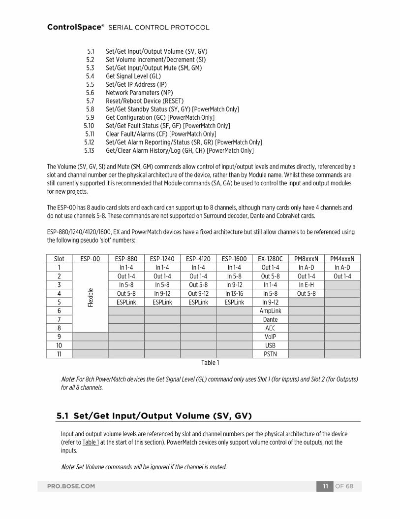
The Set and Get Module Parameter commands provide access to virtually any parameter from any signal processing module of any ControlSpace device. Devices and Modules are referenced by their label assigned via ControlSpace Designer software. Unlike the ESP and EX devices where most signal processing module labels are user-definable, only the Input and Amp Output modules can be renamed on PowerMatch devices. Note: Module labels must be unique. If two modules within the same device have the same name. then the SA, GA and MA commands will not work correctly. For example; if an Output module and a PEQ module are both named “Left” neither module will respond correctly. In combination with the module label, the parameter to change or query is identified using 1, 2 or (for a few modules only) 3 indices. These indices are unique to each type of module and are detailed at the end of this section. Automatic notification (#Module Name) In additional to querying the parameters for each module, it is also possible to receive automatic notifications when a module’s parameters change by prefixing the module name with “#” in ControlSpace Designer software. For example, by renaming module “Hall” to “#Hall”, a GA (Get Module Parameter) response will be issued over the serial connection when any of the parameters for that module are changed by other devices in the system, such as CC-16 or CC-64 user interfaces. Note: A response will not be sent if the change is made via serial command. To set or change a module parameter (SA):
SA "Module Name">Index 1>Index 2=Value<CR>
where "Module Name" is a unique Label set using Designer software > ‘greater than’ (ASCII 0x3E) is the separator between indices Index 1 Index 1 is the primary index (all modules) Index 2 Index 2 is a secondary index (some modules) = ‘equals’ (ASCII 0x3D) indicates Value follows Value Value of parameter referenced by Module/Indices
Response: <ACK> if command is successful (ASCII 0x06)
or <NAK> nn if command is received but unsuccessful (ASCII 0x15),
where nn is a 2-digit error code, detailed in the following table:
To query a module
parameter (GA): GA "Module Name">Index 1>Index 2<CR>
where "Module Name" is a unique Label set using Designer software
> ‘greater than’ (ASCII 0x3E) is the separator between indices
Code Error 01 Invalid Module Name (no match found for module name – or duplicate name) 02 Illegal Index (index value or quantity incorrect for specified module) 03 Value is out-of-range (value is not permitted for the specified parameter) 99 Unknown error

ControlSpace® SERIAL CONTROL PROTOCOL
PRO.BOSE.COM 21 OF 68
Index 1 Index 1 is the primary index (all modules) Index 2 Index 2 is a secondary index (some modules)
Response: GA "Module Name">Index 1>Index 2>=Value<CR>
For ESP processors, it is possible to send a Module command to a different device than the one on which the module resides, provided the ESPs are correctly networked together. This facility is not available for PowerMatch amplifiers so commands should be sent to each device individually.
To set or change a module parameter on a different Device (SA):
SA @ "Device Name" "Module Name">Index 1>Index 2=Value<CR>
where @ ‘at’ (ASCII 0x40) identifies that the command is for a different device "Device Name" is the unique device label from ControlSpace Designer
Response: <ACK> if command is successful (ASCII 0x06) or <NAK> nn if command is received but unsuccessful (ASCII 0x15),
where nn is a 2-digit error code – same as above To query a module parameter on a different Device (GA):
GA @ "Device Name" "Module Name">Index 1>Index 2 <CR>
where @ ‘at’ (ASCII 0x40) identifies that the command is for a different device "Device Name" is the unique device label from ControlSpace Designer
Response: GA "Module Name">Index 1>Index 2>=Value<CR>
There are a few modules (e.g. PSTN Input or VoIP Input) that, in additional to having parameters that can be adjusted, also have actions that can be invoked (e.g. Make Call) using the Module Action (MA) command.
To invoke an action for a module (MA): (Only supported on a limited number of modules)
MA "Module Name">Index 1=Parameter<CR>
where "Module Name" is the unique module name from Designer software > ‘greater than’ (ASCII 0x3E) is the separator between indices Index 1 Index 1 is the primary index = ‘equals’ (ASCII 0x3D) indicates Parameter follows Parameter Parameter required by Module Action
Response: <ACK> if command is successful (ASCII 0x06) or <NAK> nn if command is received but unsuccessful (ASCII 0x15),
where nn is a 2-digit error code – same as above
6.1 ESP/EX Module Indices

ControlSpace® SERIAL CONTROL PROTOCOL
PRO.BOSE.COM 22 OF 68
6.1.1 INPUT Module
For EX processors, inputs are displayed as a composite module with a user-specified number of channels, but are still addressed individually via serial command using the ‘channel’ label (e.g. “Input 1”). Depending on the card type or processor, the Input module has up to 5 parameters which can be controlled, selected using the appropriate value for Index 1.
EXAMPLES: SA"Input 1">3=-21<CR> Set the level for Input module “Input 1” to -21dB SA"Input 1">4=O<CR> Set the mute for Input module “Input 1” to On GA"Input 2">5<CR> Query whether phantom power is active for Input module “Input 2” GA"Input 2">5=F<CR> Response indicating phantom power for “Input 2” is currently Off
6.1.2 OUTPUT Module
For EX processors, outputs are displayed as a composite module with a user-specified number of channels, but are still addressed individually via serial command using the ‘channel’ label (e.g. “Output 2”). The Output module has 3 parameters which can be controlled, selected using the appropriate value for Index 1.
EXAMPLES: SA"Output 1">1=-3.5<CR> Set the level for Output module “Output 1” to -3.5dB SA"Output L">2=F<CR> Set the mute for Output module “Output L” to Off GA"Main L">1<CR> Query the current level for Output module “Main L” GA"Main L">1=-6<CR> Response indicating “Main L” is currently set to -6dB
Parameter Format Mic/Line II, 1U ESP or EX Legacy Mic/Line or 4x4
Inde
x 1
1 Type M,L Unused M=Mic, L=Line
2 Gain NN 0,14,24,32,44,54,64 0,14,24,42,48,54,64
3 Level (-)NN.N -60.5 to +12.0dB, 0.5dB step 4 Mute O,F,T O=On, F=Off, T=Toggle 5 Phantom O,F,T O=On, F=Off, T=Toggle
Parameter Format Value Range
Inde
x 1 1 Level (-)NN.N -60.5 to +12.0dB, 0.5dB step
2 Mute O,F,T O=On, F=Off, T=Toggle 3 Polarity O,F,T O=On, F=Off, T=Toggle

ControlSpace® SERIAL CONTROL PROTOCOL
PRO.BOSE.COM 23 OF 68
6.1.3 ESPLink Module [ESP Only]
ESPLink outputs are presented as a single composite module, but are controlled as individual channels, addressed using a combination of the module and channel name: “[ModuleName]-[ChannelName]”. By default, this would be “ESPLink 1-Ch 1” to “ESPLink 1-Ch 8” respectively, but both labels can be changed in ControlSpace Designer software.
There are 3 parameters which can be controlled for each output, selected using the appropriate value for Index 1.
EXAMPLES: SA"ESPLink 1-Ch 1">1=-3.5<CR> Set the level for channel 1 of ESPLink 1 to -3.5dB SA"ESPLink 1-Ch 5">2=F<CR> Set the mute for channel 5 of ESPLink 1 to Off GA"ESPLink 1-Ch 3">1<CR> Query the current level for channel 3 of ESPLink 1 GA"ESPLink 1-Ch 3">1=-6<CR> Response indicating channel 3 is set to -6dB
6.1.4 AMPLink Module [EX Only]
For EX processors, AMPLink outputs are displayed as a composite module with a user-specified number of channels, but are controlled as individual outputs. By default, the channels are labelled “Ch 1” to “Ch 8” and are addressed as “AMPLink-Ch 1” to “AMPLink-Ch 8” respectively, but channel labels can be changed in ControlSpace Designer software. The “AMPLink-” prefix is fixed irrespective of the displayed module names.
There are 3 parameters which can be set for each output, selected by using the appropriate value for Index 1.
EXAMPLES: SA"AMPLink-Ch 2">1=-4.5<CR> Set the level for channel 2 of AMPLink to -4.5dB SA"AMPLink-Ch 5">2=O<CR> Set the mute for channel 5 of AMPLink to ON GA"AMPLink-Ch 7">1<CR> Query the current level for channel 7 of AMPLink GA"AMPLink-Ch 7">1=-9<CR> Response indicating channel 3 is currently set to -9dB 6.1.5 DANTE I/O Modules
Direct control of Dante Input and Output modules via serial command is not currently supported. Instead, parameters can be changed indirectly using Parameter Sets.
Parameter Format Value Range
Inde
x 1 1 Level (-)NN.N -60.5 to +12.0dB, 0.5dB step
2 Mute O,F,T O=On, F=Off, T=Toggle 3 Polarity O,F,T O=On, F=Off, T=Toggle
Parameter Format Value Range
Inde
x 1 1 Level (-)NN.N -60.5 to +12.0dB, 0.5dB step
2 Mute O,F,T O=On, F=Off, T=Toggle 3 Polarity O,F,T O=On, F=Off, T=Toggle
ControlSpace® SERIAL CONTROL PROTOCOL
PRO.BOSE.COM 24 OF 68
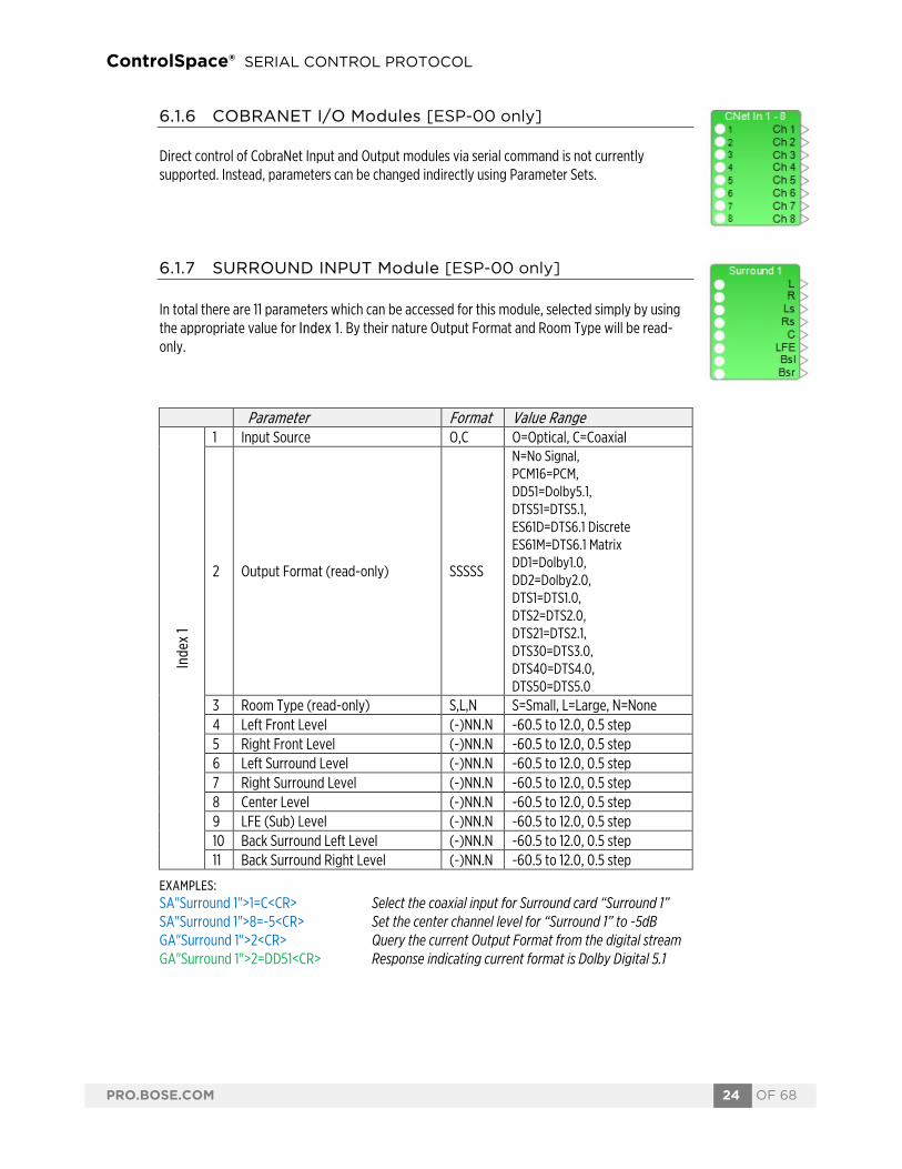
6.1.6 COBRANET I/O Modules [ESP-00 only]
Direct control of CobraNet Input and Output modules via serial command is not currently supported. Instead, parameters can be changed indirectly using Parameter Sets.
6.1.7 SURROUND INPUT Module [ESP-00 only]
In total there are 11 parameters which can be accessed for this module, selected simply by using the appropriate value for Index 1. By their nature Output Format and Room Type will be read-only.
EXAMPLES: SA"Surround 1">1=C<CR> Select the coaxial input for Surround card “Surround 1” SA"Surround 1">8=-5<CR> Set the center channel level for “Surround 1” to -5dB GA"Surround 1">2<CR> Query the current Output Format from the digital stream GA"Surround 1">2=DD51<CR> Response indicating current format is Dolby Digital 5.1
Parameter Format Value Range
Inde
x 1
1 Input Source O,C O=Optical, C=Coaxial
2 Output Format (read-only) SSSSS
N=No Signal, PCM16=PCM, DD51=Dolby5.1, DTS51=DTS5.1, ES61D=DTS6.1 Discrete ES61M=DTS6.1 Matrix DD1=Dolby1.0, DD2=Dolby2.0, DTS1=DTS1.0, DTS2=DTS2.0, DTS21=DTS2.1, DTS30=DTS3.0, DTS40=DTS4.0, DTS50=DTS5.0
3 Room Type (read-only) S,L,N S=Small, L=Large, N=None 4 Left Front Level (-)NN.N -60.5 to 12.0, 0.5 step 5 Right Front Level (-)NN.N -60.5 to 12.0, 0.5 step 6 Left Surround Level (-)NN.N -60.5 to 12.0, 0.5 step 7 Right Surround Level (-)NN.N -60.5 to 12.0, 0.5 step 8 Center Level (-)NN.N -60.5 to 12.0, 0.5 step 9 LFE (Sub) Level (-)NN.N -60.5 to 12.0, 0.5 step 10 Back Surround Left Level (-)NN.N -60.5 to 12.0, 0.5 step 11 Back Surround Right Level (-)NN.N -60.5 to 12.0, 0.5 step
ControlSpace® SERIAL CONTROL PROTOCOL
PRO.BOSE.COM 25 OF 68
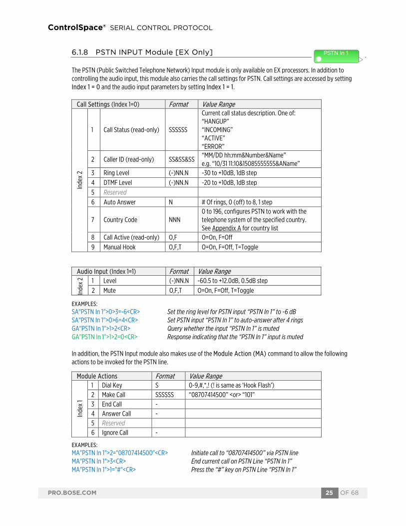
6.1.8 PSTN INPUT Module [EX Only]
The PSTN (Public Switched Telephone Network) Input module is only available on EX processors. In addition to controlling the audio input, this module also carries the call settings for PSTN. Call settings are accessed by setting Index 1 = 0 and the audio input parameters by setting Index 1 = 1.
EXAMPLES: SA"PSTN In 1">0>3=-6<CR> Set the ring level for PSTN input “PSTN In 1” to -6 dB SA"PSTN In 1">0>6=4<CR> Set PSTN input “PSTN In 1” to auto-answer after 4 rings GA"PSTN In 1">1>2<CR> Query whether the input “PSTN In 1” is muted GA"PSTN In 1">1>2=O<CR> Response indicating that the “PSTN In 1” input is muted
In addition, the PSTN Input module also makes use of the Module Action (MA) command to allow the following actions to be invoked for the PSTN line.
EXAMPLES: MA"PSTN In 1">2="08707414500"<CR> Initiate call to “08707414500” via PSTN line MA"PSTN In 1">3<CR> End current call on PSTN Line “PSTN In 1” MA"PSTN In 1">1="#"<CR> Press the “#” key on PSTN Line “PSTN In 1”
Call Settings (Index 1=0) Format Value Range
Inde
x 2
1 Call Status (read-only) SSSSSS
Current call status description. One of: “HANGUP” “INCOMING” “ACTIVE” “ERROR”
2 Caller ID (read-only) SS&SS&SS “MM/DD hh:mm&Number&Name” e.g. “10/31 11:10&15085555555&AName”
3 Ring Level (-)NN.N -30 to +10dB, 1dB step 4 DTMF Level (-)NN.N -20 to +10dB, 1dB step 5 Reserved Voice Tx/Rx Level 6 Auto Answer N # Of rings, 0 (off) to 8, 1 step
7 Country Code NNN 0 to 196, configures PSTN to work with the telephone system of the specified country. See Appendix A for country list
8 Call Active (read-only) O,F O=On, F=Off 9 Manual Hook O,F,T O=On, F=Off, T=Toggle
Audio Input (Index 1=1) Format Value Range
Inde
x 2 1 Level (-)NN.N -60.5 to +12.0dB, 0.5dB step
2 Mute O,F,T O=On, F=Off, T=Toggle
Module Actions Format Value Range
Inde
x 1
1 Dial Key S 0-9,#,*,! (! is same as ‘Hook Flash’) 2 Make Call SSSSSS “08707414500” <or> “101” 3 End Call - 4 Answer Call - 5 Reserved 6 Ignore Call -

ControlSpace® SERIAL CONTROL PROTOCOL
PRO.BOSE.COM 26 OF 68
6.1.9 PSTN OUTPUT Module [EX Only]
The PSTN (Public Switched Telephone Network) Output module is only available on EX processors. There are 2 parameters which can be controlled, selected using the appropriate value for Index 1.
EXAMPLES: SA"PSTN Out 1">1=-8.0<CR> Set the level for “PSTN Out 1” to -8.0dB GA"PSTN Out 1">2<CR> Query the state of the mute for PSTN Output “PSTN Out 1” GA"PSTN Out 1">2=F<CR> Response indicating that “PSTN Out 1” is currently unmuted
6.1.10 VoIP INPUT Module [EX Only]
The VoIP (Voice over IP) Input module is only available on EX processors. In addition to controlling the audio input, this module also carries the call settings for the VoIP Line. Call settings are accessed using Index 1 = 0, and the audio input parameters using Index 1 = 1. Note: VoIP network and registration settings are configured via a web page interface, accessible via ControlSpace Designer software or directly by entering the VoIP IP address in a browser.
Parameter Format Value Range
Inde
x 1 1 Level (-)NN.N -60.5 to +12.0dB, 0.5dB step
2 Mute O,F,T O=On, F=Off, T=Toggle
Call Settings (Index 1=0) Format Value Range
Inde
x 2
0 Account Status (read-only)
SSSSSS
Current account status description. One of: “NOT_CONFIGURED” “CONFIGURED” “P2P_REGISTERED” “PROXY_REGISTERING” “PROXY_REGISTERED” “PROXY_TIMEOUT”
1 Call Status (read-only)
SSSSSS
Current call status description. One of: “INCOMING” “DIALING” “RINGBACK” “ACTIVE” “HANGUP” “HOLD_STATE_PEER”
2 Caller ID (read-only) SS<SS@SS> “ Name <sip:User@Domain/Host>” e.g. “ ConfRm12 <sip:[email protected]>"
3 Reserved Ring Level 4 Reserved DTMF Level 5 Reserved Voice Tx/Rx Level 6 Call Active (read-only) O,F O=On, F=Off 7 Auto Answer N # Of rings, 0 (off) to 8, 1 step
Audio Input (Index 1=1) Format Value Range
Inde
x 2 1 Level (-)NN.N -60.5 to +12.0dB, 0.5dB step
2 Mute O,F,T O=On, F=Off, T=Toggle

ControlSpace® SERIAL CONTROL PROTOCOL
PRO.BOSE.COM 27 OF 68
EXAMPLES: SA"VoIP In 1">1>1=-6<CR> Set the level for “VoIP In 1” to -6 dB SA"VoIP In 1">0>7=5<CR> Set VoIP input “VoIP In 1” to auto-answer after 5 rings GA"VoIP In 1">0>1<CR> Query the current call status for “VoIP In 1” GA"VoIP In 1">0>1="ACTIVE"<CR> Response indicating “VoIP In 1” has an active call
In addition, the VoIP Input module also makes use of the Module Action (MA) command to allow the following actions to be invoked for the VoIP line.
EXAMPLES MA"VoIP In 1">2="08707414500"<CR> Initiate call to “08707414500” via “VoIP In 1” MA"VoIP In 1">5<CR> Answer the incoming call on VoIP Line “VoIP In 1” MA"VoIP In 1">1="0"<CR> Press the “0” key on VoIP Line “VoIP In 1”
6.1.11 VoIP OUTPUT Module [EX Only]
The VoIP Output module is only available on EX processors. There are 2 parameters which can be controlled, selected using the appropriate value for Index 1.
EXAMPLES: SA"VoIP Out 1">1=-12<CR> Set the level for “VoIP Out 1” to -12dB GA"Line 1">2<CR> Query the state of the mute for VoIP output “Line 1” GA"VoIP Out 1">2=O<CR> Response indicating that “Line 1” is currently muted
6.1.12 USB INPUT Module [EX Only]
The USB Input module is currently only supported on EX processors. The two channels of the USB Input are controlled individually, with the value for Index 1 selecting the channel and Index 2 selecting between the two parameters.
EXAMPLES: SA"USB In 1">1>1=-21<CR> Set the level of the left channel of USB Input “USB In 1” to -21dB GA"USB In 1">2>2<CR> Query whether the right channel of USB Input “USB In 1” is muted GA"USB In 1">2>2=F<CR> Response indicating the right channel of “USB In 1” is currently unmuted
Module Actions Format Value Range
Inde
x 1
1 Dial Key S 0-9,#,* 2 Make Call SSSSSSS “08707414500” <or> “101” <or> “sip:[email protected]” 3 End Call - 4 Answer Call - 5 Transfer Call SSSSSSS “08707414500” <or> “101” <or> “sip:[email protected]”
Parameter Format Value Range
Inde
x 1 1 Level (-)NN.N -60.5 to +12.0dB, 0.5dB step
2 Mute O,F,T O=On, F=Off, T=Toggle
Parameter Format Value Range
Inde
x 2 1 Level (-)NN.N -60.5 to +12.0dB, 0.5dB step
2 Mute O,F,T O=On, F=Off, T=Toggle

ControlSpace® SERIAL CONTROL PROTOCOL
PRO.BOSE.COM 28 OF 68
6.1.13 USB OUTPUT Module [EX Only]
The USB Output module is currently only supported on EX processors. The two channels of the USB Output are controlled individually, with the value for Index 1 selecting the channel and Index 2 selecting between the two parameters.
EXAMPLES: SA"USB Out 1">2>1=-16.5<CR> Set the level of the right channel of USB Output “USB Out 1” to -16.5dB GA"USB Out 1">1>2<CR> Query whether the left channel of USB Output “USB Out 1” is muted GA"USB Out 1">1>2=F<CR> Response indicating the left channel of “USB Out 1” is currently unmuted
6.1.14 ACOUSTIC ECHO CANCELLER Module [EX Only] The Acoustic Echo Canceller module on EX processors has a total of 12 channels that can be sub-divided into 4 modules, each with a dedicated reference input in ControlSpace Designer software, but remains a single module of 12 channels via serial command, addressed as “AEC”. Index 1 is used to select the input (1-12) and Index 2 is used to select the parameter to adjust per the table below.
EXAMPLES: SA"AEC">6>5=O<CR> Mute input 6 of the “AEC” module SA"AEC">4>7=2<CR> Set the NLP Control for input 4 to Medium GA"AEC">8>9<CR> Query the current NR level for input 8 GA"AEC">16>2=9<CR> Response indicating the NR level for input 8 is 9dB
Parameter Format Value Range
Inde
x 2 1 Level (-)NN.N -60.5 to +12.0dB, 0.5dB step
2 Mute O,F,T O=On, F=Off, T=Toggle
Input Parameters (Index 1 = 1-12) Format Value Range
Inde
x 2
1 Reserved Return Level
2 Reserved Return Mute 3 Reserved Send level
4 Reserved Send Mute 5 Internal Mute O,F,T O=On, F=Off, T=Toggle 6 AEC Enable O,F,T O=On, F=Off, T=Toggle 7 NLP Control N 1 = Light, 2 = Medium, 3 = Strong 8 CN Enable (global) O,F,T O=On, F=Off, T=Toggle 9 NR Level NN 0 to 32dB, 1 step 10 Reference (read-only) N 1 to 4

ControlSpace® SERIAL CONTROL PROTOCOL
PRO.BOSE.COM 29 OF 68
6.1.15 AGC Module (Enhanced) [EX only]
The Enhanced AGC module has a maximum of 32 inputs and is only available on EX processors. It has 10 parameters that can be controlled for each input, plus one global parameter. The Input (or Overall Module) is selected by Index 1 and the parameter to be controlled by Index 2 per the tables below:
Index 1: Selects desired Input (1-32) or 0 for Output/Module
EXAMPLES: SA"AGC 1">0>1=20.0<CR> Set the Max Gain that can be applied across all channels of “AGC 1” to 20dB SA"AGC 1">2>2=-6.0<CR> Set the Target Level – Minimum for channel 2 of “AGC 1” to -6.0 dB GA"Mic AGC">6>10<CR> Query the current state of the Bypass for channel 10 of “Mic AGC” GA"Mic AGC">6>10=F<CR> Response indicating Bypass for channel 10 of “Mic AGC” is OFF
Output/Module (Index 1 = 0) Format Value Range
Ix 2
1 Max Total Gain NN.N 0 to 60.0 dB, 1 Step
Input Parameters (Index 1 = 1-32) Format Value Range
Inde
x 2
1 Activity Threshold (-)NN.N -70.0 to 0 dB, 1 Step
2 Target Level - Minimum (-)NN.N -40.0 to 24 dB, 1 Step
3 Target Level - Maximum (-)NN.N -40.0 to 24 dB, 1 Step
4 Cut Rate NNNN.N 0.0 to 9000 dB/s, 0.1 Step
5 Cut Range NN.N 0 to 30 dB, 1 Step
6 Cut Hold NN.N 0 to 60 s, 1 Step
7 Boost Rate NNNN.N 0.0 to 9000 dB/s, 0.1 Step
8 Boost Range NN.N 0 to 30 dB, 1 Step
9 Boost Hold NN.N 0 to 60 s, 1 Step
10 Bypass O,F,T O=On, F=Off, T=Toggle
11 Reserved
12 Reserved
13 Reserved
14 Reserved
15 Reserved

ControlSpace® SERIAL CONTROL PROTOCOL
PRO.BOSE.COM 30 OF 68
6.1.16 AGC Module (Legacy)
This module has 3 parameters selected using the appropriate value for Index 1. Note: The mono AGC module does not have Detector selection and hence Index 1=1 would not be used.
EXAMPLES: SA"AGC 1">1=M<CR> Set the detector of stereo AGC module “AGC 1” to Mix SA"AGC 1">2=-20<CR> Set the threshold for AGC module “AGC 1” to -20dBFS GA"BGM">6<CR> Query the current state of the bypass for “BGM” GA"BGM">6=F<CR> Response indicating bypass for module “BGM” is Off
6.1.17 ARRAY EQ Module
For this module, Index 1 should always be set to 1. There are 7 parameters which can be controlled on the Array EQ module, selected using the appropriate value for Index 2. By the nature of the module you would not use the Array parameters (7 & 8) and the Advanced parameters (1, 2 & 3) at the same time.
EXAMPLES: SA"Array EQ 1">1>7=6<CR> Set the qty of RoomMatch™ modules for “Array EQ 1”to 6 SA"Main L">1>8=80<CR> Set the Vertical coverage angle for “Main L” to 80 deg GA"Array EQ">1>5<CR> Query the current state of Bypass for “Array EQ” GA"Array EQ">1>5=O<CR> Response indicating Bypass for “Array EQ” is currently On
Parameter Format Value Range
Inde
x 1
1 Detector (stereo) L,R,M L=Left, R=Right, M=Mix
2 Threshold (-)NN.N 0 to -40 dBFS 0.5 Step
3 Reserved
4 Reserved
5 Reserved
6 Bypass O,F,T O=On, F=Off, T=Toggle
Index 1 = 1 Parameter Format Value Range
Inde
x 2
1 Center Freq NNN 220 to 700Hz
2 Tilt NN.N 0.0 to 10.0. 0.1 step
3 Gain (-)NN.N -12.0dB to 2.0dB, 0.1dB step
4 Reserved (Type = AS) 5 Bypass O,F,T O=On, F=Off, T=Toggle
6 Advanced O,F,T O=On, F=Off, T=Toggle
7 # Modules N 2 to 8, 1 step
8 Vertical Angle NN 20-100, 5 step

ControlSpace® SERIAL CONTROL PROTOCOL
PRO.BOSE.COM 31 OF 68
6.1.18 AMM – GAIN SHARING Module [EX/1U ESP Only] The Gain Sharing AMM (Automatic Mic Mixer) module can be configured with 4-32 inputs. Index 1 is used to select the input (1-32) and Index 2 is used to select the parameter to adjust per the table below. In addition, there are some output and overall module parameters that may be adjusted by setting Index 1 = 0.
Index 1: Selects desired Input (1-32) or 0 for Output/Module
EXAMPLES: SA"AMM 1">0>2=T<CR> Toggle the state of the output mute for module “AMM 1” SA"AMM 1">0>3=1.00<CR> Set the Slope parameter for “AMM 1” to 1.00 SA"AMM 1">6>1=-10<CR> Set the Gain for input 6 of “AMM 1” to -10dB SA"AMM 1">4>3=2<CR> Set the Priority for input 4 of “AMM 1” to 2 (2nd highest) SA"AMM 1">24>4=O<CR> Set the Bypass for input 24 of “AMM 1” to On GA"AMM 1">16>2<CR> Query the current state of Mute for input 16 of “AMM 1” GA"AMM 1">16>2=O<CR> Response indicating input 16 of “AMM 1” is Muted
Output/Module (Index 1 = 0) Format Value Range
Inde
x 2
1 Gain (-)NN.N -60.5 to 12.0 dB, 0.5 step
2 Mute O,F,T O=On, F=Off, T=Toggle
3 Slope N.NN 0.01 to 2.00, 0.01 step
4 Attack NN.N 0.5 to 100.0 ms, 0.5 step
5 Hold NNNN.N 0 to 1000.0 ms, 1 step
6 Decay NNNNN.N 5 to 50000.0 ms, 5 step
7 Input RMS Avg. NNN.N 1 to 500.0 ms, 1 step
8 Output RMS Avg. NNN.N 1 to 500.0 ms, 1 step
9 Bypass All O,F,T O=On, F=Off, T=Toggle
Input (Index 1 = 1-32) Format Value Range
Inde
x 2
1 Gain (-)NN.N -60.5 to 12.0 dB, 0.5 step
2 Mute O,F,T O=On, F=Off, T=Toggle 3 Priority N 1,2,3,4,5 (1=Highest)
4 Bypass O,F,T O=On, F=Off, T=Toggle 5 Mute Group NN 0=None, 1 to # channels -1

ControlSpace® SERIAL CONTROL PROTOCOL
PRO.BOSE.COM 32 OF 68
6.1.19 AMM - GATED Module (Legacy) [ESP Only] The legacy Gated Automatic Mic Mixer (AutoMix) module is available with 4, 6 or 8 inputs. Index 1 is used to select the input (1-8) and Index 2 is used to select the parameter to adjust per the table below. In addition there are some output parameters that may be adjusted by setting Index 1 = 0. Some parameters are only relevant for particular detection modes (such as Push-to-talk) and would otherwise be unused. Index 1: Selects desired Input (1-8) or 0 for Output
EXAMPLES: SA"AMM 1">0>3=T<CR> Toggle the state of the output mute for module “AMM 1” SA"AMM 1">6>4=-40<CR> Set the Threshold for input 6 of “AMM 1” to -40dB SA"AMM 1">4>3=2<CR> Set the Detection mode for input 4 of “AMM 1” to Last On GA"AMM 1">3>1<CR> Query the current state of Priority for input 3 of “AMM 1” GA"AMM 1">3>1=O<CR> Response indicating input 3 of “AMM 1” is set to Priority
Output/Module (Index 1 = 0) Format Value Range
Inde
x 2
1 Gain (-)NN.N -60.5 to 0.0 dB, 0.5 step
2 NOM O,F,T O=On, F=Off, T=Toggle
3 Mute O,F,T O=On, F=Off, T=Toggle
4 NOM Limit N 1 to # Channels (4,6,8)
Input Parameters (Index 1 = 1-8) Format Value Range
Inde
x 2
1 Priority O, F, T O=On, F=Off, T=Toggle
2 Gain (-)NN.N -60.5 to 0.0 dB, 0.5 step
3 Detection N 1=Threshold, 2=LastOn, 3=PushToTalk, 4=Bypass
4 Threshold (-)NN.N -80.0 to 0.0 dB, 0.5 step 5 Gate Depth (-)NN.N -70.0 to 0.0 dB, 0.5 step 6 Hold NNNNN 1 to 50000 ms, 1 step 7 Ducking Depth (-)NN.N -60.0 to 0.0 dB, 0.5 step 8 Decay NNNNN 5 to 50000 ms, 1 step 9 Reserved 10 High Pass NNNN 20 to 1000 Hz 11 Low Pass NNNNN 1000 to 20000 Hz 12 RMS Avg. NNN 1 to 500 ms, 1 step 13 Reserved 14 Attack NN.N 0.5 to 100.0ms, 0.5 step 15 Push to Talk O, F, T O=On, F=Off, T=Toggle 16 Mute O, F, T O=On, F=Off, T=Toggle
ControlSpace® SERIAL CONTROL PROTOCOL
PRO.BOSE.COM 33 OF 68
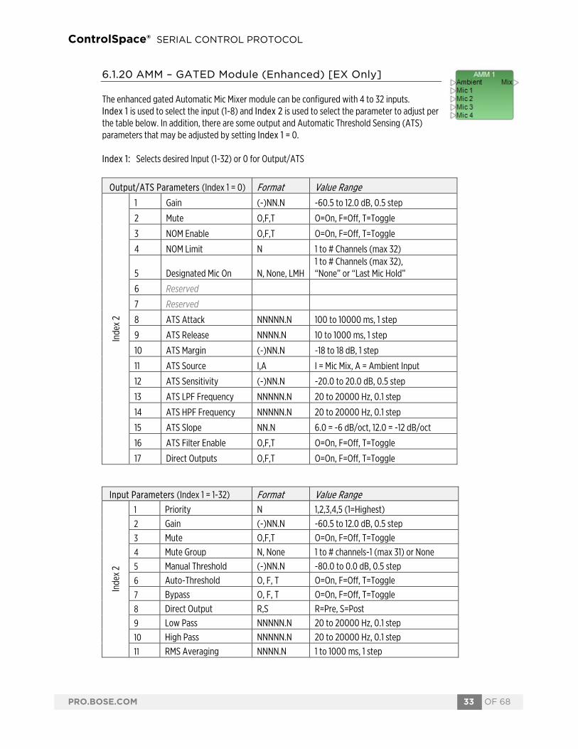
6.1.20 AMM – GATED Module (Enhanced) [EX Only]
The enhanced gated Automatic Mic Mixer module can be configured with 4 to 32 inputs. Index 1 is used to select the input (1-8) and Index 2 is used to select the parameter to adjust per the table below. In addition, there are some output and Automatic Threshold Sensing (ATS) parameters that may be adjusted by setting Index 1 = 0. Index 1: Selects desired Input (1-32) or 0 for Output/ATS
Output/ATS Parameters (Index 1 = 0) Format Value Range
Inde
x 2
1 Gain (-)NN.N -60.5 to 12.0 dB, 0.5 step
2 Mute O,F,T O=On, F=Off, T=Toggle
3 NOM Enable O,F,T O=On, F=Off, T=Toggle
4 NOM Limit N 1 to # Channels (max 32)
5 Designated Mic On N, None, LMH 1 to # Channels (max 32), “None” or “Last Mic Hold”
6 Reserved
7 Reserved
8 ATS Attack NNNNN.N 100 to 10000 ms, 1 step
9 ATS Release NNNN.N 10 to 1000 ms, 1 step
10 ATS Margin (-)NN.N -18 to 18 dB, 1 step
11 ATS Source I,A I = Mic Mix, A = Ambient Input
12 ATS Sensitivity (-)NN.N -20.0 to 20.0 dB, 0.5 step
13 ATS LPF Frequency NNNNN.N 20 to 20000 Hz, 0.1 step
14 ATS HPF Frequency NNNNN.N 20 to 20000 Hz, 0.1 step
15 ATS Slope NN.N 6.0 = -6 dB/oct, 12.0 = -12 dB/oct
16 ATS Filter Enable O,F,T O=On, F=Off, T=Toggle
17 Direct Outputs O,F,T O=On, F=Off, T=Toggle
Input Parameters (Index 1 = 1-32) Format Value Range
Inde
x 2
1 Priority N 1,2,3,4,5 (1=Highest) 2 Gain (-)NN.N -60.5 to 12.0 dB, 0.5 step 3 Mute O,F,T O=On, F=Off, T=Toggle 4 Mute Group N, None 1 to # channels-1 (max 31) or None 5 Manual Threshold (-)NN.N -80.0 to 0.0 dB, 0.5 step 6 Auto-Threshold O, F, T O=On, F=Off, T=Toggle 7 Bypass O, F, T O=On, F=Off, T=Toggle 8 Direct Output R,S R=Pre, S=Post 9 Low Pass NNNNN.N 20 to 20000 Hz, 0.1 step 10 High Pass NNNNN.N 20 to 20000 Hz, 0.1 step 11 RMS Averaging NNNN.N 1 to 1000 ms, 1 step

ControlSpace® SERIAL CONTROL PROTOCOL
PRO.BOSE.COM 34 OF 68
EXAMPLES: SA"AMM 1">0>2=T<CR> Toggle the state of the output mute for module “AMM 1” SA"AMM 1">6>7=-40<CR> Set the Manual Threshold for input 6 of “AMM 1” to -40dB SA"AMM 1">4>2=P<CR> Set the Control mode for input 4 of “AMM 1” to PTT GA"AMM 1">3>1<CR> Query the current state of Priority for input 3 of “AMM 1” GA"AMM 1">3>1=2<CR> Response indicating input 3 of “AMM 1” is set to Priority level 2
6.1.21 COMPRESSOR/LIMITER Module
This module has 6 parameters that can be controlled, selected using the appropriate value for Index 1. For a mono Compressor module set the Detection Input to ‘L’ (Left) to use the Signal input or ‘S’ to use the Sidechain input, ‘R’ and ‘M’ are unused.
EXAMPLES: SA"CompLim 1">1=M<CR> Set the detection input for module “CompLim 1” to Mix SA"CompLim 1">2=-20<CR> Set the threshold for module “CompLim 1” to -20dBFS GA"Main Out">6<CR> Query the current state of the bypass for “Main Out” GA"Main Out">6=F<CR> Response indicating bypass for “Main Out” is currently Off
Input Parameters (Index 1 = 1-32) Format Value Range
Inde
x 2
12 Ducker Depth (-)NN.N -60.0 to 0.0 dB, 0.5 step 13 Gate Depth (-)NN.N -70.0 to 0.0 dB, 0.5 step 14 Gate Attack NNN.N 0.5 to 500 ms, 0.5 step 15 Gate Hold NNNNN.N 1 to 50000 ms, 1 step 16 Gate Decay NNNNN.N 1 to 50000 ms, 1 step 17 NOM Gain O, F, T O=On, F=Off, T=Toggle
Parameter Format Value Range
Inde
x 1
1 Detect Input L,R,M,S L=Left, R=Right, M=Mix, S=Sidechain
2 Threshold (-)NN.N 0 to -40 dBFS, 0.5 step
3 Ratio NN.N 1 to 20, 0.1 step
4 Attack NNN.N 0.5 to 100 ms, 0.5 step
5 Release NNNN.N 1 to 1000 ms, 0.5 step
6 Bypass O,F,T O=On, F=Off, T=Toggle

ControlSpace® SERIAL CONTROL PROTOCOL
PRO.BOSE.COM 35 OF 68
6.1.22 CONFERENCE ROOM ROUTER Module [EX] The Conference Room Router module is only available on EX processors. The number of Far End Inputs, Pre-AEC Mic Inputs, Aux and Overhead Outputs are user-definable in ControlSpace Designer software and can be queried as part of the Configuration parameters. This module has many controllable Parameters, organized into groups, selected by Index 1. With Index 1 = 0 the configuration of the module can be determined to allow the appropriate controls to be configured on the external control panel.
With Index 1 = 1 the room/output controls can be accessed including the master volume control and the master mic mix and non-mic mix levels.
Configuration Parameters (Index 1 = 0) Format Value Range
Inde
x 2
1 #Far End Inputs (Read-only)
N 0 to 8
2 #Pre-AEC Mic Inputs (Read-only
NN 0 to 32
3 #Overhead Outputs (Read-only)
NN 0 to 16
4 Room Combine Member (Read-only)
O,F O=On, F=Off
5 RC Room Number (Read-only)
N 0 (not in RC Group) 1 to 6
6 RC Room Name (Read-only)
SSSSS e.g. “CRR 1” <or> “Room 1”
7
Room Combine State (Read-only)
SSSSS “{1|2}” = 1-2 Split, “{1+2}” = 1-2 Joined e.g. “{1|2}{2+3}” = Room 1 solo, Rooms 2 & 3 combined
8 Stereo > Mono Attenuation (Read-only)
-N.N -3.0,-4.0,-5.0 or -6.0 dB
9 Matrix Mode (Read-only)
N,A N=Normal, A=Advanced
Room/Output Parameters (Index 1 = 1) Format Value Range
Inde
x 2
1 Master Volume (-)NN.N -60.5 to 12.0 dB, 0.5 step
2 Master Mute O,F,T O=On, F=Off, T=Toggle
3 Mic Mix Level (-)NN.N -60.5 to 12.0 dB, 0.5 step
4 Mic Mix Mute O,F,T O=On, F=Off, T=Toggle
5 Non-Mic Mix Level (-)NN.N -60.5 to 12.0 dB, 0.5 step
6 Non-Mic Mix Mute O,F,T O=On, F=Off, T=Toggle
7 Pre-AEC Mic Mix Level (-)NN.N -60.5 to 12.0 dB, 0.5 step
8 Pre-AEC Mic Mix Mute O,F,T O=On, F=Off, T=Toggle
9 RC Group Number N 1 to 6

ControlSpace® SERIAL CONTROL PROTOCOL
PRO.BOSE.COM 36 OF 68
With Index 1 = 2 the Program level/mute and up-to 8 Far End input levels/mutes can be controlled.
With Index 1 = 3-6 the Normal or Advanced Matrix can be controlled, with Index 1 = 3/5 controlling whether the cross-point is On/Off and Index 1 = 4/6 controlling the level at the cross-point per the table below:
The cross-point to control is selected with Index 2 in the format (input,output). Since the inputs and outputs of the matrix change with the configuration, the easiest way to identify which cross-point to control is to view the matrix in ControlSpace Designer software. Note that some changes to the matrix will be overriden by other changes (e.g. changing the Stereo > Mono attenuation). EXAMPLES: SA"CRR 1">1>2=T<CR> Toggle the state of the master mute for module “CRR 1” SA"CRR 1">2>1=-40.0<CR> Set the Program level for “CRR 1” to -40.0 dB SA"CRR 1">1>7=All<CR> Route the Mic Mix for “CRR 1” to program output SA"Room 2">2>12=O<CR> Mute Far End input 4 of CRR called “Room 2” SA"CRR 3">3>(1,1)=O<CR> Turn on the Input 1 to Output 1 cross-point of the Normal Matrix for “CRR 3” GA"CRR 1">1>1<CR> Query the Master Volume level of “CRR 1” GA"CRR 1">1>1=-3.0<CR> Response indicating Master Volume level is set to -3.0dB
Program/Far End Inputs (Index 1 = 2) Format Value Range
Inde
x 2
1 Program Level (-)NN.N -60.5 to 12.0 dB, 0.5 step
2 Program Mute O,F,T O=On, F=Off, T=Toggle
3 Far End 1 Level (-)NN.N -60.5 to 12.0 dB, 0.5 step
4 Far End 1 Mute O,F,T O=On, F=Off, T=Toggle
5 Far End 2 Level (-)NN.N -60.5 to 12.0 dB, 0.5 step
6 Far End 2 Mute O,F,T O=On, F=Off, T=Toggle
7 Far End 3 Level (-)NN.N -60.5 to 12.0 dB, 0.5 step
8 Far End 3 Mute O,F,T O=On, F=Off, T=Toggle
9 Far End 4 Level (-)NN.N -60.5 to 12.0 dB, 0.5 step
10 Far End 4 Mute O,F,T O=On, F=Off, T=Toggle
11 Far End 5 Level (-)NN.N -60.5 to 12.0 dB, 0.5 step
12 Far End 5 Mute O,F,T O=On, F=Off, T=Toggle
13 Far End 6 Level (-)NN.N -60.5 to 12.0 dB, 0.5 step
14 Far End 6 Mute O,F,T O=On, F=Off, T=Toggle
15 Far End 7 Level (-)NN.N -60.5 to 12.0 dB, 0.5 step
16 Far End 7 Mute O,F,T O=On, F=Off, T=Toggle
17 Far End 8 Level (-)NN.N -60.5 to 12.0 dB, 0.5 step
18 Far End 8 Mute O,F,T O=On, F=Off, T=Toggle
Matrices (Index 1 = 3-6) Parameter Format Value Range
Inde
x 1
3 Normal Matrix
Cross-point On/Off O,F,T O=On, F=Off, T=Toggle
4 Cross-point Level (-)NN.N -60.5 to 0.0 dB, 0.5 step
5 Advanced Matrix
Cross-point On/Off O,F,T O=On, F=Off, T=Toggle
6 Cross-point Level (-)NN.N -60.5 to 0.0 dB, 0.5 step

ControlSpace® SERIAL CONTROL PROTOCOL
PRO.BOSE.COM 37 OF 68
6.1.23 CROSSOVER Module
Available parameters for the Crossover vary per section (Low, Mid and High) and depending on the type of Crossover there can be 2, 3 or 4 sections.
Index 1 is used to select the Crossover section to control per the Crossover type per the table below.
Index 2 is then used to select the parameter to change, dependant on the Crossover section selected by Index 1 per the tables below.
EXAMPLES: SA"X-Over">1>2=80<CR> Set the freq. for the Low section of “X-Over” to 80Hz SA"X-Over">1>1=But24<CR> Set the Low section of “X-Over” to Butterworth 24dB/oct GA"X-Over 2">4>5<CR> Query mute status of the High section of 4way “X-Over 2” GA"X-Over 2">4>5=F<CR> Response indicating High section of “X-Over 2” is unmuted
2 Way 3 Way 4 Way
Inde
x 1
1 LOW LOW LOW 2 HIGH MID LO MID 3 - HIGH HIMID 4 - - HIGH
LOW Parameter Format Value Range
Inde
x 2
1 Type SSSSS e.g. But12 2 Frequency NNNNN 20Hz to 20000Hz 3 Reserved
4 Polarity O,F,T O=On, F=Off, T=Toggle 5 Mute O,F,T O=On, F=Off, T=Toggle
Filter type descriptors Type Slope Value Butterworth 6dB/oct But6 12dB/oct But12 18dB/oct But18 24dB/oct But24 36dB/oct But36 48dB/oct But48 Bessel 12dB/oct Bes12 18dB/oct Bes18 24dB/oct Bes24 36dB/oct Bes36 48dB/oct Bes48 Linkwitz-Reily 12dB/oct Lin12 24dB/oct Lin24 36dB/oct Lin36 48dB/oct Lin48
MID Parameter Format Value Range
Inde
x 2
1 Type (HPF) SSSSS e.g. But12 2 Frequency NNNNN 20Hz to 20000Hz 3 Type (LPF) SSSSS e.g. But12 4 Frequency NNNNN 20Hz to 20000Hz 5 Reserved
6 Polarity O,F,T O=On, F=Off, T=Toggle 7 Mute O,F,T O=On, F=Off, T=Toggle
HIGH Parameter Format Value Range
Inde
x 2
1 Type SSSSS e.g. But12 2 Frequency NNNNN 20Hz to 20000Hz 3 Reserved
4 Polarity O,F,T O=On, F=Off, T=Toggle 5 Mute O,F,T O=On, F=Off, T=Toggle

ControlSpace® SERIAL CONTROL PROTOCOL
PRO.BOSE.COM 38 OF 68
6.1.24 DELAY Module
Delay modules are available with 1, 2, 4 or 8 output taps. The delay time for each tap can be adjusted individually or bypassed. The maximum module delay is 3 seconds for the ESP-00 and 1 second for 1U ESP and EX processors. Index 1 is used to select the desired tap and Index 2 is used to select the parameter to adjust per the table below. Index 1: Selects the desired Delay output tap (1-8)
EXAMPLES: SA"Delay 1">4>1=2592<CR> Set the delay time for tap 4 of module “Delay 1” to 54msec (54msec = 0.054sec, 0.054x48000 = 2592 samples) SA"Out Delay">2>2=F<CR> Set bypass for tap 2 of Delay module “Out Delay” to Off GA"Delay 2">1>1<CR> Query the current delay time for tap 1 of “Delay 2” GA"Delay 2">1>1=9600<CR> Response with delay time for tap 1 of “Delay 2” is 200ms
6.1.25 DUCKER Module
There are 6 parameters that can be controlled for this module, selected using the appropriate value for Index 1. Index 1=1 is reserved and should not be used. Ducker will be active if either the Sidechain is above Threshold OR the Engage Ducker logic input is On.
EXAMPLES: SA"Ducker 1">2=-5<CR> Set the threshold for module “Ducker 1” to -5dBFS SA"Ducker 1">3=-60<CR> Set the range (attenuation) for “Ducker 1” to -60dBFS GA"Page Over">7<CR> Query the current state of the bypass for “Page Over” GA"Page Over">7=O<CR> Response indicating bypass for “Page Over” is On
Parameter Format ESP-00 1U ESP/EX
Inde
x 2 1 Delay time NNNNNN 0 to 144000 samples (3s) 0 to 48000 samples (1s)
2 Bypass O,F,T O=On, F=Off, T=Toggle
Parameter Format Value Range
Inde
x 1
1 Reserved
2 Threshold (-)NN.N 0 to -40 dBFS 0.5 Step
3 Range (-)NN.N 0 to -70dBFS, 0.5 step
4 Attack NNN.N 0.5 to 100ms, 0.5 step
5 Hold NNNN 0 to1000ms, 1 step
6 Decay NNNNN 5 to 50000ms, 1 step
7 Bypass O,F,T O=On, F=Off, T=Toggle
8 Engage Ducker (Logic) O,F,T O=On, F=Off, T=Toggle

ControlSpace® SERIAL CONTROL PROTOCOL
PRO.BOSE.COM 39 OF 68
6.1.26 GAIN Module
Gain modules have a single Level and Mute parameter irrespective of the number of channels. These are selected using Index 1 per the table below.
EXAMPLES: SA"Main Volume">2=F<CR> Set mute state of Gain module “Main Volume” to un-muted GA"Gain 4">1<CR> Query the current level of Gain module “Gain 4” GA"Gain 4">1=3<CR> Response indicating level of “Gain 4” is currently 3dB
6.1.27 GATE Module
There are 7 parameters which can be set for this module, selected by using the appropriate value for Index 1. For a mono Gate module set the Detector to ‘L’ (Left) to use the Signal input or ‘S’ to use the Sidechain input, ‘R’ and ‘M’ are unused.
EXAMPLES: SA"Gate 1">6=2000<CR> Set the Decay time for module “Gate 1” to 2000ms SA"Gate 1">7=T<CR> Toggle the state of the Bypass for module “Gate 1” GA"Gate1">7<CR> Query the current state of the Bypass for “Gate 1” GA"Gate 1">7=F<CR> Response indicating Bypass for module “Gate 1” is Off
6.1.28 GPO Module
Depending on the device the GPO module may have 5 or 8 GPO pins. The pin to control is selected using Index 1. The ESP-00 can have two cards, presented as separate modules, addressed by the module name.
Index 1: Output pin: 1-8 Value: State: O = On, F = Off, T = Toggle EXAMPLES: SA"GP Out”>2=O<CR> Turn on GPO pin 2 on a fixed I/O device SA"GP Out 2”>3=T<CR> Toggle GPO pin 3 on the second card of an ESP-00 with 2 GPIO cards GA"GP Out 1">4<CR> Query the state of GPO pin 4 GA"GP Out 1">4=F<CR> Response indicating GPO pin 4 is Off
Parameter Format Value Range
Inde
x 1
1 Level (-)NN.N -60.5.0dB to +12.0dB, 0.5dB step 2 Mute O,F,T O=On, F=Off, T=Toggle
Parameter Format Value Range
Inde
x 1
1 Detector L,R,M,S L=Left, R=Right, M=Mix, S=Sidechain
2 Threshold (-)NN.N 0 to -40 dBFS 0.5 Step
3 Range (-)NN.N 0 to -70dBFS, 0.5 step
4 Attack NNN.N 0.5 to 100ms, 0.5 step
5 Hold NNNN 0 to 1000ms, 1 step
6 Decay NNNNN 5 to 50000ms, 1 step
7 Bypass O,F,T O=On, F=Off, T=Toggle

ControlSpace® SERIAL CONTROL PROTOCOL
PRO.BOSE.COM 40 OF 68
6.1.29 1/3 OCTAVE GRAPHIC EQ Module Each of the 31 bands can be adjusted individually, selected using the appropriate value for Index 1. In addition, there is also a “Bypass all” function selected by setting Index 1 to 32.
EXAMPLES: SA"GEQ 1">18=-3.5<CR> Reduce the 1kHz band of GEQ module “GEQ 1” by 3.5dB SA"GEQ 1">24=5<CR> Increase the 4kHz band of GEQ module “GEQ 1” by 5dB GA"GEQ Bar">11<CR> Query the current level for the 200Hz band of “GEQ Bar” GA"GEQ Bar">11=-6<CR> Response indicating the 200Hz band is currently at -6dB
Frequency Format Value Range
Inde
x 1
1 20Hz (-)NN.N -15.0dB to +15.0dB, 0.1dB step 2 25Hz (-)NN.N -15.0dB to +15.0dB, 0.1dB step 3 31.5Hz (-)NN.N -15.0dB to +15.0dB, 0.1dB step 4 40Hz (-)NN.N -15.0dB to +15.0dB, 0.1dB step 5 50Hz (-)NN.N -15.0dB to +15.0dB, 0.1dB step 6 63Hz (-)NN.N -15.0dB to +15.0dB, 0.1dB step 7 80Hz (-)NN.N -15.0dB to +15.0dB, 0.1dB step 8 100Hz (-)NN.N -15.0dB to +15.0dB, 0.1dB step 9 125Hz (-)NN.N -15.0dB to +15.0dB, 0.1dB step 10 160Hz (-)NN.N -15.0dB to +15.0dB, 0.1dB step 11 200Hz (-)NN.N -15.0dB to +15.0dB, 0.1dB step 12 250Hz (-)NN.N -15.0dB to +15.0dB, 0.1dB step 13 315Hz (-)NN.N -15.0dB to +15.0dB, 0.1dB step 14 400Hz (-)NN.N -15.0dB to +15.0dB, 0.1dB step 15 500Hz (-)NN.N -15.0dB to +15.0dB, 0.1dB step 16 630Hz (-)NN.N -15.0dB to +15.0dB, 0.1dB step 17 800Hz (-)NN.N -15.0dB to +15.0dB, 0.1dB step 18 1kHz (-)NN.N -15.0dB to +15.0dB, 0.1dB step 19 1.25kHz (-)NN.N -15.0dB to +15.0dB, 0.1dB step 20 1.6kHz (-)NN.N -15.0dB to +15.0dB, 0.1dB step 21 2kHz (-)NN.N -15.0dB to +15.0dB, 0.1dB step 22 2.5kHz (-)NN.N -15.0dB to +15.0dB, 0.1dB step 23 3.15kHz (-)NN.N -15.0dB to +15.0dB, 0.1dB step 24 4kHz (-)NN.N -15.0dB to +15.0dB, 0.1dB step 25 5kHz (-)NN.N -15.0dB to +15.0dB, 0.1dB step 26 6.3kHz (-)NN.N -15.0dB to +15.0dB, 0.1dB step 27 8kHz (-)NN.N -15.0dB to +15.0dB, 0.1dB step 28 10kHz (-)NN.N -15.0dB to +15.0dB, 0.1dB step 29 12.5kHz (-)NN.N -15.0dB to +15.0dB, 0.1dB step 30 16kHz (-)NN.N -15.0dB to +15.0dB, 0.1dB step 31 20kHz (-)NN.N -15.0dB to +15.0dB, 0.1dB step 32 Bypass All O,F,T O=On, F=Off, T=Toggle 33 Reserved (Mute)

ControlSpace® SERIAL CONTROL PROTOCOL
PRO.BOSE.COM 41 OF 68
6.1.30 LOGIC INPUT Module [EX Only]
The Logic Input module has a user-definable number of inputs (max. 16) and is used to drive down-stream logic programmed in the design. The pin to control is selected using the appropriate value for Index 1. Currently the only parameter is the State, set by Index 2 = 1.
Index 1: Input pin: 1-16 Index 2: 1 = State: Value: O = On, F = Off, T = Toggle, P = Pulse (momentary action) EXAMPLES: SA"Logic Input 1">10>1=O<CR> Set input 10 for module “Logic Input 1” to On SA"Logic Input 1">6>1=P<CR> Perform a momentary push of input 6 (automatically resets to Off) GA"System Mode">2>1<CR> Query the state of input 2 on module “System Mode” GA"System Mode">2>1=O<CR> Response indicating input 2 of module “System Mode” is On
6.1.31 LOGIC OUTPUT Module [EX Only]
The Logic Output module has a user-definable number of outputs (max. 16) and is used to convey logic states from the system to the outside world to indicate system mode or status etc. Typically, this module would be queried rather than set, but both are permitted. The pin to control is selected using the appropriate value for Index 1. Currently the only parameter is the State, set by Index 2 = 1.
Index 1: Output pin: 1-16 Index 2: 1 = State: Value: O = On, F = Off, T = Toggle EXAMPLES: SA"Logic Output 2">2>1=O<CR> Set output 2 on module “Logic Output 2” to On SA"Logic Output 2">3>1=T<CR> Toggle the state of output 3 on module “Logic Output 2” GA"Status">4>1<CR> Query the state of output 4 on module “Status” GA"Status">4>1=F<CR> Response indicating output 4 on module “Status” is Off
6.1.32 LOGIC PROCESSING Module [EX Only]
The Logic Block can be configured with a user-definable number of inputs and outputs (max. 16) and is unusual in that in that it is a container for logic gates, adding an additional layer. Controllable Gates within the Logic Block are addressed as though they are additional parameters of the parent Logic Block. Parameters indicated as read-only should not be set, otherwise unexpected side-effects will occur. Index 1 selects between the inputs (Index 1 = 1), outputs (Index 1 = 2) and any other controllable gate inside the block (Index 1 =3 or above).
Inputs and Outputs are always allocated indices 1 and 2 respectively, then any other controllable gates are allocated the next available index (ID) as they are added to the block.
Parameter Notes
Inde
x 1 1 Inputs (read-only) Query state of input (O=On, F=Off)
2 Outputs (read-only) Query state of output (O=On, F=Off)
3+ Controllable Gates/Logic Gates within the Logic Block are enumerated in the order in which they were added.

ControlSpace® SERIAL CONTROL PROTOCOL
PRO.BOSE.COM 42 OF 68
Index 2: Selects the desired input, output or channel of the controllable gate inside the Logic Block. Index 3: Selects the desired parameter, for each type of gate, per the tables below.
6.1.32.1 TOGGLE/FF Gate
The Toggle/FF Gate has a single controllable parameter per channel, the Toggle State, and an overall Set and Reset accessible when Index 2 (channel) = 0.
EXAMPLES: SA"Logic Block 1">3>0>1=P<CR> Set all outputs of Toggle/FF gate (ID:3) inside “Logic Block 1” to On SA"Mic Logic">6>2>1=O<CR> Force On ch2 of Toggle/FF gate (ID:6) inside “Mic Logic” block GA"Logic Block 1">4>3>1 <CR> Query the current state of ch3 of Toggle/FF gate (ID:4) GA"Logic Block 1">4>3>1 =F<CR> Response indicating ch3 of Toggle/FF gate (ID:4) is Off
6.1.32.2 PULSE Gate
The Pulse Gate has 4 controllable parameters per channel, selected using the appropriate value for Index 3.
EXAMPLES: SA"Main Logic">5>1>2=400<CR> Set Off time for ch1 of Pulse gate (ID:5) inside “Main Logic” to 400mS SA"Logic Block 1">5>4>3=O<CR> Set ch4 of Pulse gate (ID:5) inside “Logic Block 1” to give a single pulse GA"Logic Block 1">3>2>4 <CR> Query whether ch2 of Pulse gate (ID:3) is currently forced ON GA"Logic Block 1">3>2>4 =O<CR> Response indicating ch2 of Pulse gate (ID:3) is forced ON
6.1.32.3 DEBOUNCE Gate
The Debounce Gate has 2 controllable parameters per channel, selected using Index 3.
Master Flip Flop (Index 2 = 0) Format Value Range
Inde
x 3 1 Set All Outputs ON O,F,T,P O=On, F=Off, T=Toggle, P=Pulse
2 Reset All Outputs OFF O,F,T,P O=On, F=Off, T=Toggle, P=Pulse
Channel Toggle (Index 2 = 1-16) Format Value Range
Ix 3
1 Toggle State O,F,T O=On, F=Off, T=Toggle
Parameter Format Value Range
Inde
x 3
1 On Time NNNN 100 to 6000 ms, Step 100
2 Off Time NNNN 100 to 6000 ms, Step 100
3 Single Pulse O,F,T O=On, F=Off, T=Toggle
4 Force ON O,F,T O=On, F=Off, T=Toggle
5 Output State (read-only) O,F O=On, F=Off
Parameter Format Value Range
Inde
x 3 1 On Delay NNNN 100 to 6000 ms, Step 100
2 Off Delay NNNN 100 to 6000 ms, Step 100
3 Output State (read-only) O,F O=On, F=Off

ControlSpace® SERIAL CONTROL PROTOCOL
PRO.BOSE.COM 43 OF 68
EXAMPLES: SA"Rm Combine">4>2>1=800<CR> Set On Delay for ch2 of Debounce (ID:4) in “Rm Combine” to 800mS SA"Logic Block 2">6>3>2=200<CR> Set Off Delay for ch3 of Debounce (ID:6) in “Logic Block 2” to 200mS GA"Logic Block 1">6>4>3<CR> Query current output state for ch4 of Debounce (ID:6) GA"Logic Block 1">6>4>3=F<CR> Response indicating ch4 output of Debounce (ID:6) is currently OFF
6.1.33 MATRIX MIXER Module
The Matrix Mixer module supports a user-definable number of inputs and outputs (max. 32) and allows cross-points to be turned on/off or the level at the cross-point to be adjusted. Index 1 is used to select whether the cross-point state (on/off) or level will be adjusted per the table below.
Index 2 is then used to select which cross-point is to be controlled; stepping through the available outputs for input 1, then through the available outputs for input 2, and so on. Index 2 will be the same irrespective of whether the state (on/off) or level is being controlled, but Index 1 and the Value will change. In the following tables: M = # of inputs and N = # of outputs in the module.
EXAMPLES: SA"Matrix 1">1>2=O<CR> Set cross-point 2 (input 1, output2) for “Matrix 1” to On SA"Mix">2>8=-20<CR> Set level for cross-point 8 (in2,out4 for 4x4) “Mix” to -20dB GA"My Matrix">1>16<CR> Query the current state for cross-point 16 (in4,out4 for 4x4) GA"My Matrix">1=16=F<CR> Response indicating cross-point 16 is currently Off
Parameter Notes
Inde
x 1 1 On/Off Set Cross-point On/Off
2 Level Set Level
Cross-point On/Off (Index 1 = 1) Format Value Range
Inde
x 2
1 Cross-point(1,1) O,F,T O=On, F=Off, T=Toggle
2 Cross-point(1,2) O,F,T O=On, F=Off, T=Toggle
Index 2 = (Input # -1) x Size of Matrix + Output #:
MxN Cross-point(M,N) O,F,T O=On, F=Off, T=Toggle
Cross-point Level (Index 1 = 2) Format Value Range
Inde
x 2
1 Cross-point(1,1) (-)NN.N -60.5 to 0.0dB, 0.5 step
2 Cross-point(1,2) (-)NN.N -60.5 to 0.0dB, 0.5 step
Index 2 = (Input # -1) x Size of Matrix + Output #:
MxN Cross-point(M,N) (-)NN.N -60.5 to 0.0dB, 0.5 step

ControlSpace® SERIAL CONTROL PROTOCOL
PRO.BOSE.COM 44 OF 68
6.1.34 PARAMETRIC EQ Module
Parametric EQ modules are available with 3, 5, 7 or 9 fixed bands, or a user-defined number of bands (max 16). The same parameters are adjustable for each band. Index 1 is used to select which band to adjust (1-16) and Index 2 is used to select the parameter to adjust per the table below. Index 1: Selects desired Parametric EQ band 1-16
The parameters in use for each band will be dependent on the Type of filter selected per the table below.
EXAMPLES: SA"PEQ 1">1>1=2000<CR> Set the frequency for band 1 of module “PEQ 1” to 2kHz SA"Room EQ">2>5=LC<CR> Use a ‘Low Cut” (High Pass) filter for band 2 of “Room EQ” GA"House L">5>3<CR> Query the gain for band 5 of PEQ module “House L” GA"House L">5>3=-2<CR> Response indicating band 5 of “House L” is at -2dB
Parameter Format Value Range
Inde
x 2
1 Frequency NNNNN 20 to 20000Hz
2 Q NN.N 0.10 to 10.0, 0.1 step
3 Gain (-)NN.N -20.0dB to +20.0dB, 0.1dB step
4 Slope (-)NN.N 0,-6,-12dB/oct 5 Type SS B, HS, LS, HC, LC, N (see below)
6 Bypass O,F,T O=On, F=Off, T=Toggle
Type String Freq. Q Gain Slope Bypass Band B o o o o High Shelf HS o o o Low Shelf LS o o o High Cut (Low Pass) HC o o o Low Cut (High pass) LC o o o Notch N o o o o

ControlSpace® SERIAL CONTROL PROTOCOL
PRO.BOSE.COM 45 OF 68
6.1.35 PEAK/RMS LIMITER Module
This module has 6 parameters that can be controlled, selected using the appropriate value for Index 1. For a mono Peak/RMS Limiter module, set the Detection Input to ‘L’ (Left) to use the Signal input or ‘S’ to use the Sidechain input, ‘R’ and ‘M’ are unused. Parameters indicated as ‘Reserved’ should not be used.
EXAMPLES: SA"PkRMSLim 1">1=R<CR> Set the Detect Input for stereo “PkRMSLim 1” to R(ight) SA"Limiter 1">7=-20<CR> Set the RMS limiter threshold for “Limiter 1” to -20dBFS GA"Array L">2<CR> Query the Peak limiter threshold for “Array L” GA"Array L">2=-6<CR> Response indicating the Peak limiter threshold is -6dBFS
6.1.36 ROUTER Module
The Router module is available with a user-definable number of inputs and outputs, but the command format remains the same. Index 1 is used to select the output channel and the Value indicates the desired input to be routed to that output.
Index 1: Output number: 1-32 Value: Input number: 0-32 where 0 = Off (no input routed) EXAMPLES: SA"Router 1">1=5<CR> Set output 1 of Router module “Router 1” to input 5 SA"Router 2">3=0<CR> Set output 3 of Router module “Router 2” to Off (no input) GA"Select">4<CR> Query which input is routed to output 4 of “Select” GA"Select">4=2<CR> Response indicating output 4 of “Select” is set to input 2
Parameter Format Value Range
Inde
x 1
1 Detect Input L,R,M,S L=Left, R=Right, M=Mix, S=Sidechain
2 PK Threshold (-)NN.N 0 to -40 dBFS 0.5 Step
3 Reserved (Ratio)
4 Reserved (Peak Attack)
5 Reserved (Peak Release)
6 Bypass O,F,T O=On, F=Off, T=Toggle
7 RMS Threshold (-)NN.N 0 to -40 dBFS 0.5 Step
8 RMS Attack NNNNN 500 to 10,000ms, 100 step
9 RMS Release NNNNN 500 to 10,000ms, 100 step
10 Reserved (Soft Clip Enable)

ControlSpace® SERIAL CONTROL PROTOCOL
PRO.BOSE.COM 46 OF 68
6.1.37 SIGNAL GENERATOR Modules
The available parameters for Signal Generator modules vary according to the type (Sine, Noise and Sweep), but the same command format is used. Index 1 is used to select the type of Signal Generator module being controlled per the table below.
When a Noise module is used it is possible to switch between White or Pink noise by setting Index 1 to values 2 or 3 respectively, without additional indices (e.g. SA ”Noise 1”>1=3 to set Pink Noise)
Index 2 is then used to select the parameter to change dependent on the Generator type selected by Index 1 per the tables below.
EXAMPLES: SA"Sine 1">1>1=500<CR> Set the frequency for Sine Generator “Sine 1” to 500Hz SA"Noise 1">1=2<CR> Set Noise Generator “Noise 1” to White noise SA"Noise 1">2>2=O Set the Mute state of White noise gen “Noise 1” to Muted GA"Sweep 1">4>2<CR> Query whether module “Sweep 1” is set to Slow or Fast GA"Sweep 1">4>2=F<CR> Response indicating “Sweep 1” is currently set to Fast
Signal
Inde
x 1
1 Sine Wave 2 White Noise 3 Pink Noise 4 Sweep
Sine Wave (Index 1 = 1) Format Value Range
Inde
x 2 1 Frequency NNNNN 20 to 20000Hz
2 Gain (-)NN.N -60.5 to +12.0dB, 0.5 step
3 Mute O,F,T O=On, F=Off, T=Toggle
White Noise (Index 1 = 2) Format Value Range
Inde
x 2 1 Gain (-)NN.N -60.5 to +12.0dB, 0.5 step
2 Mute O,F,T O=On, F=Off, T=Toggle
Pink Noise (Index 1 = 3) Format Value Range
Inde
x 2 1 Gain (-)NN.N -60.5 to +12.0dB, 0.5 step
2 Mute O,F,T O=On, F=Off, T=Toggle
Sweep (Index 1 = 4) Format Value Range
Inde
x 2
1 Gain (-)NN.N -60.5 to +12.0dB, 0.5 step
2 Slow/Fast S,F S=Slow,F=Fast
3 Repeat O,F O=On (repeat), F=Off (no repeat)
4 Start/Stop O,F O=On (start), F=Off (stop)

ControlSpace® SERIAL CONTROL PROTOCOL
PRO.BOSE.COM 47 OF 68
6.1.38 SOURCE SELECTOR Module
The Source Selector module is available in both mono and stereo versions, each with a user-definable number of inputs (Max. 16), but the command format is the same. Index 1 is always 1 and the Value is used to select the input.
Index 1: Channel (always =1) Value: Input number: 1-16 EXAMPLES: SA"Selector 1">1=5<CR> Set Source Selector module “Selector 1” to input 5 GA"Bar">1<CR> Query which input is currently selected for module “Bar” GA"Bar">1=2<CR> Response indicating input 2 is currently selected
6.1.39 SPEAKER PARAMETRIC EQ Module
The Speaker Parametric EQ module has 9 bands of parametric EQ, a band-pass filter and alignment delay. The same parameters are adjustable for each parametric EQ band. Index 1 is used to select the EQ band to adjust (1-9) or 0 to select the Band Pass, Alignment Delay and EQ Gain parameters. Index 2 is then used to select the desired parameter to adjust per the tables below. Index 1: Selects the desired EQ Band (1-9) or 0 for Band Pass/Delay/EQ Gain
Band Pass/Align Delay/ EQ Gain (Index 1 = 0) Format Value Range
Inde
x 2
1 Reserved (Preset Name)
2 Reserved (IsBosePreset)
3 Gain (-)NN.N -15.0B to +15.0dB, 0.5dB step
4 Align Delay NNN 0 to 480 samples
5 Type (High) *1 e.g. But12
6 Frequency NNNNN 20 to 20000Hz
7 Type (Low) *1 e.g. But12
8 Frequency NNNNN 20 to 20000Hz
9 Lo Bypass O,F,T O=On, F=Off, T=Toggle
10 Hi Bypass O,F,T O=On, F=Off, T=Toggle
11 Polarity O,F,T O=On, F=Off, T=Toggle
Filter type descriptors Type Slope Value Butterworth 6dB/oct But6 12dB/oct But12 18dB/oct But18 24dB/oct But24 36dB/oct But36 48dB/oct But48 Bessel 12dB/oct Bes12 18dB/oct Bes18 24dB/oct Bes24 36dB/oct Bes36 48dB/oct Bes48 Linkwitz-Reily 12dB/oct Lin12 24dB/oct Lin24 36dB/oct Lin36 48dB/oct Lin48

ControlSpace® SERIAL CONTROL PROTOCOL
PRO.BOSE.COM 48 OF 68
The parameters in use for each band will be dependent on the Type of filter selected per the table below.
EXAMPLES: SA"SPEQ 1">0>5=Bes36<CR> Set the HP Filter type for “SPEQ 1” to Bessel 36dB/oct SA"Array L">2>1=200<CR> Set the frequency for PEQ band 2 of “Array L” to 200Hz GA"Array L">0>3<CR> Query the EQ gain SPEQ module “Array L” GA"Array L">0>3=2<CR> Response indicating the EQ gain is currently at +2dB
6.1.40 STANDARD MIXER Module
The Standard Mixer module is available with a user-defined number of inputs and outputs (max. 32), and allows control of input level/mute, output level/mute and cross-point routing. Cross-point routing can be set using two different methods; the first routes all the outputs for a given input with a single command, the second allows an individual cross-point (input,output) to be controlled directly. Index 1 is used to select whether an input, output or a cross-point (and the cross-point method) is being controlled per the table below.
PEQ Band (Index 1 = 1-9) Format Value Range
Inde
x 2
1 Frequency NNNNN 20 to 20000Hz
2 Q NN.N 0.10 to 10.0, 0.1 step
3 Gain (-)NN.N -20.0dB to +20.0dB, 0.1dB step
4 Reserved (Slope) 5 Type XX B, HS, LS, N (see below)
6 Bypass O,F,T O=On, F=Off, T=Toggle
Type String Freq. Q Gain Bypass Band B o o o o High Shelf HS o o o Low Shelf LS o o o Notch N o o o o
Parameters Notes
Inde
x 1
1 Input Set Input Parameters 2 Output Set Output Parameters 3 Cross-point A Route Input to Multiple Outputs 4 Cross-point B Set Cross-point On/Off Directly

ControlSpace® SERIAL CONTROL PROTOCOL
PRO.BOSE.COM 49 OF 68
Index 2 is then used to select the parameter to set or query dependent on whether an input, output or cross-point was selected by the first index. In the following tables M = # of inputs and N = # of outputs in the module.
Cross-point Routing A – Routing an input to multiple outputs with a single command (Index 1=3)
The desired output routing for an input is sent as an array of eight Hex values, where each Hex value represents the routing for 4 channels converted from Binary. This allows the routing for 32 outputs to be set in a single command. Even when the Standard Mixer module used has less than 32 outputs all 8 Hex values should be sent. Example: To route input 1 to outputs: 1,6,9,12,15,18,21,22,23,24,27,28,29 & 31 the array of Hex values would be ‘84924F3A’ as illustrated:
Cross-point Routing B – Controlling a cross-point (input,output) directly (Index 1=4) Index 2: (input,output) Value: O=On,F=Off,T=Toggle
EXAMPLES: SA"StdMixer 1">1>1=-3<CR> Set the level for input 1 of module “StdMixer 1” to -3dB SA"My Mixer">2>16=O<CR> Set mute state for output 8 of module “My Mixer” to On SA"Mix">3>2=C0000000<CR> Route input 2 to outputs 1 & 2 on “Mix” using cross-point 1 SA"Theatre">4>(4,5)=O<CR> Route input 4 to output 5 on “Theatre” using cross-point 2 GA"Mix">3>4<CR> Query the routing for input 4 of “Mix” using cross-point 1 GA"Mix">3>4=03000000<CR> Response indicating input 4 is routed to outputs 7&8 GA"Theatre">4>(6,8)<CR> Query whether input 6 is routed to output 8 on “Theatre” GA"Theatre">4>(6,8)=F<CR> Response indicating input 6 is not routed to output 8
Input Parameters (Index 1 = 1) Format Value Range
Inde
x 2
1 Input 1 Level (-)NN.N -60.5 to +12.0dB, 0.5 step
2 Input 1 Mute O,F,T O=On, F=Off, T=Toggle
Mx2-1 Input M Level (-)NN.N -60.5 to +12.0dB, 0.5 step
Mx2 Input M Mute O,F,T O=On, F=Off, T=Toggle
Output Parameters (Index 1 = 2) Format Value Range
Inde
x 2
1 Output 1 Level (-)NN.N -60.5 to +12.0dB, 0.5 step 2 Output 1 Mute O,F,T O=On, F=Off, T=Toggle Nx2-1 Output N Level (-)NN.N -60.5 to +12.0dB, 0.5 step Nx2 Output N Mute O,F,T O=On, F=Off, T=Toggle
Cross-point Routing A (Index 1 = 3) Format Value Range
Inde
x 2 1 Input 1 Routing XXXXXXXX Hex representation of routing
2 Input 1 Routing XXXXXXXX Hex representation of routing M Input M Routing XXXXXXXX Hex representation of routing
Output Channels 1 2 3 4 5 6 7 8 9 10 11 12 13 14 15 16 17 18 19 20 21 22 23 24 25 26 27 28 29 30 31 32
Input 1 O - - - - O - - O - - O - - O - - O - - O O O O - - O O O - O - Hex Value 8 4 9 2 4 F 3 A

ControlSpace® SERIAL CONTROL PROTOCOL
PRO.BOSE.COM 50 OF 68
6.1.41 TONE CONTROL EQ Module
The Tone EQ module has a gain and bypass control for each of the 3 bands, selected using the appropriate value for Index 1 per the following table.
EXAMPLES: SA"ToneEQ L">1=-4<CR> Set the Low band of Tone EQ module “ToneEQ L” to -4dB SA"Hall EQ">6=O<CR> Bypass the High band of Tone EQ module “Hall EQ” GA"ToneEQ 1">3<CR> Query the current level for the Mid band of “ToneEQ 1” GA"ToneEQ 1">3=-3<CR> Response indicating the Mid band is currently at -3dB
Parameter Format Value Range
Inde
x 1
1 Low Gain (-)NN.N -15.0dB to +15.0dB, 0.1dB step
2 Low Bypass O,F,T O=On, F=Off, T=Toggle
3 Mid Gain (-)NN.N -15.0dB to +15.0dB, 0.1dB step
4 Mid Bypass O,F,T O=On, F=Off, T=Toggle 5 High Gain (-)NN.N -15.0dB to +15.0dB, 0.1dB step
6 High Bypass O,F,T O=On, F=Off, T=Toggle

ControlSpace® SERIAL CONTROL PROTOCOL
PRO.BOSE.COM 51 OF 68
6.2 PowerMatch® Module Indices
6.2.1 INPUT Module
There are 3 parameters which can be set for this module selected by using the appropriate value for Index 1.
Note: Digital Sensitivity is global and set via the properties for the PowerMatch device.
EXAMPLES: SA"In A">1=4<CR> Set the Input Sensitivity for “In A” to 4dBu SA"Desk L">3=O<CR> Select Digital input source for input “Desk L” GA"In D">2<CR> Query the current Mute state for “In D” GA"In D">2=F<CR> Response indicating that “In D” is currently un-muted
6.2.2 SIGNAL GENERATOR Module
Index 1 should always be set to 5 to access this module. There are 8 parameters that can be controlled for this module, selected using the appropriate value for Index 2.
Note: The routing for the Signal Generator is set via the Matrix Mixer module, where it appears as input 9. Index 1: PowerMatch Signal Generator (always=5)
EXAMPLES: SA"SigGen 1">5>4=1<CR> Set the Signal Generator “SigGen 1” to output Pink Noise SA"SigGen 1">5>1=-10<CR> Set the level for Signal Generator “SigGen 1” to -10dB GA"SigGen 1">5>3<CR> Query the current Mute state for module “SigGen 1” GA"SigGen 1">5>3=O<CR> Response indicating that “SigGen 1” is currently muted
Parameter Format Value Range
Inde
x 1 1 Analog Sensitivity NN.N 0, 4, 12, 24 dBu
2 Mute O,F,T O=On, F=Off, T=Toggle
3 Source O,F,T O=Digital, F=Analog, T=Toggle
(Index 1 = 5) Parameter Format Value Range
Inde
x 2
1 Level (-)NN.N -60.5 to 12.0dB, 0.5 step
2 Repeat O, F O=On (Repeat), F=Off
3 Mute O,F,T O=On, F=Off, T=Toggle
4 Type N 1 to 4
5 Tone Freq NNNNN 20 to 20000Hz
6 Start Freq NNNNN 20 to 20000Hz
7 End Freq NNNNN 20 to 20000Hz
8 Duration N 1 to 5s, step 1
Sig Gen Type
1 Pink Noise
2 White Noise
3 Tone
4 Sweep

ControlSpace® SERIAL CONTROL PROTOCOL
PRO.BOSE.COM 52 OF 68
6.2.3 INPUT PARAMETRIC EQ Module
The Input Parametric EQ modules have 5 bands. The same parameters are adjustable for each band. Index 1 is used to select the band to adjust (1-5) and Index 2 is used to select the parameter to adjust per the table below. Index 1: Selects desired Parametric EQ band 1-5
The parameters in use for each band will be dependent on the Type of filter selected per the table below.
Note: Labels for PowerMatch Signal Processing modules (other than Input and Amp Output) are fixed and cannot be changed in the same way as ESP modules. Module labels are “PEQ-5band A” through to “PEQ-5band H” per the channel.
EXAMPLES: SA"PEQ-5band A">1>1=2000<CR> Set the frequency for band 1 of channel A to 2kHz SA"PEQ-5band D">4>5=HS<CR> Use a ‘High Shelf” filter for band 4 of channel D GA"PEQ-5band F">3>6<CR> Query the Bypass state for band 3 of channel F” GA"PEQ-5band F">3>6=F<CR> Response indicating Bypass for band 3 is Off
Parameter Format Value Range
Inde
x 2
1 Frequency NNNNN 20 to 20000Hz
2 Q NN.N 0.10 to 10.0, 0.1 step
3 Gain (-)NN.N -20.0dB to +20.0dB, 0.1dB step
4 Slope -NN 0,-6,-12dB/oct 5 Type XX B, HS, LS, HC, LC, N (see below)
6 Bypass O,F,T O=On, F=Off, T=Toggle
Type String Freq. Q Gain Slope Bypass Band B o o o o High Shelf HS o o o Low Shelf LS o o o High Cut (Low Pass) HC o o o Low Cut (High pass) LC o o o Notch N o o o o

ControlSpace® SERIAL CONTROL PROTOCOL
PRO.BOSE.COM 53 OF 68
6.2.4 ARRAY EQ Module
Due to the internal architecture of the PowerMatch, the Array EQ module is actually addressed as band 6 of the Input Parametric EQ module, hence Index 1 = 6. Index 2 is then used to select the parameter to adjust per the table below. Parameters that are indicated as ‘Reserved’ should not be used.
Index 1: Selects Array EQ band of Input Parametric module (always=6)
Note: Labels for PowerMatch Signal Processing modules (other than Input and Amp Output) are fixed and cannot be changed in the same way as ESP modules. Module labels are “PEQ-5band A” through to “PEQ-5band H” per the channel. EXAMPLES: SA"PEQ-5band A">6>4=4.080<CR> Set the Array settings for channel A, Array EQ module to 4x modules &
80 deg vertical coverage SA"PEQ-5band C">6>3=-6<CR> Set the Gain for channel C Array EQ to -6dB GA"PEQ-5band E">6>6<CR> Query the Bypass state for Array EQ on channel E GA"PEQ-5band E">6>6=O<CR> Response indicating Bypass for channel E is On
(Index 1 = 6) Parameter Format Value Range
Inde
x 2
1 Center Freq NNN 220 to 700Hz
2 Tilt NN.N 0.0 to 10.0. 0.1 step
3 Gain (-)NN.N -12.0dB to +2.0dB, 0.1dB step
4 Array M.VVV M=2 to 8, VVV=20 to 100, 5 step
5 Reserved (Type=AS)
6 Bypass O,F,T O=On, F=Off, T=Toggle
7 Advanced O,F,T O=On, F=Off, T=Toggle
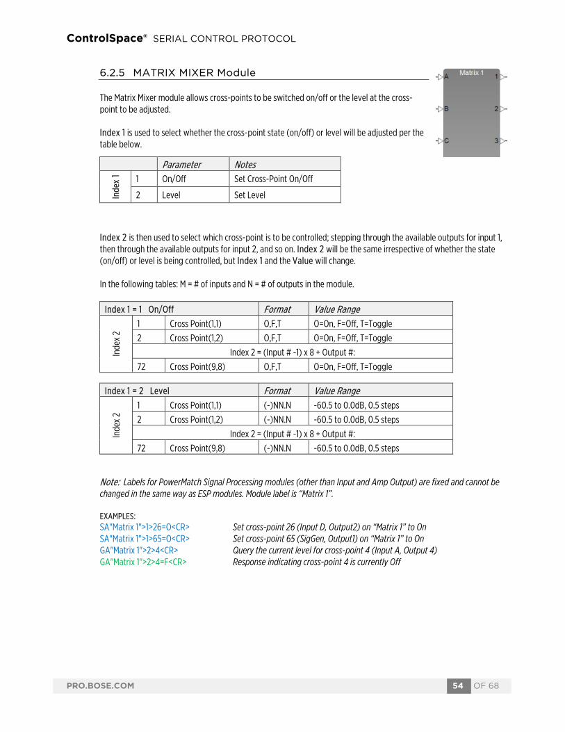
ControlSpace® SERIAL CONTROL PROTOCOL
PRO.BOSE.COM 54 OF 68
6.2.5 MATRIX MIXER Module
The Matrix Mixer module allows cross-points to be switched on/off or the level at the cross-point to be adjusted. Index 1 is used to select whether the cross-point state (on/off) or level will be adjusted per the table below.
Index 2 is then used to select which cross-point is to be controlled; stepping through the available outputs for input 1, then through the available outputs for input 2, and so on. Index 2 will be the same irrespective of whether the state (on/off) or level is being controlled, but Index 1 and the Value will change. In the following tables: M = # of inputs and N = # of outputs in the module.
Note: Labels for PowerMatch Signal Processing modules (other than Input and Amp Output) are fixed and cannot be changed in the same way as ESP modules. Module label is “Matrix 1”. EXAMPLES: SA"Matrix 1">1>26=O<CR> Set cross-point 26 (Input D, Output2) on “Matrix 1” to On SA"Matrix 1">1>65=O<CR> Set cross-point 65 (SigGen, Output1) on “Matrix 1” to On GA"Matrix 1">2>4<CR> Query the current level for cross-point 4 (Input A, Output 4) GA"Matrix 1">2>4=F<CR> Response indicating cross-point 4 is currently Off
Parameter Notes
Inde
x 1 1 On/Off Set Cross-Point On/Off
2 Level Set Level
Index 1 = 1 On/Off Format Value Range
Inde
x 2
1 Cross Point(1,1) O,F,T O=On, F=Off, T=Toggle
2 Cross Point(1,2) O,F,T O=On, F=Off, T=Toggle
Index 2 = (Input # -1) x 8 + Output #:
72 Cross Point(9,8) O,F,T O=On, F=Off, T=Toggle
Index 1 = 2 Level Format Value Range
Inde
x 2
1 Cross Point(1,1) (-)NN.N -60.5 to 0.0dB, 0.5 steps
2 Cross Point(1,2) (-)NN.N -60.5 to 0.0dB, 0.5 steps
Index 2 = (Input # -1) x 8 + Output #:
72 Cross Point(9,8) (-)NN.N -60.5 to 0.0dB, 0.5 steps

ControlSpace® SERIAL CONTROL PROTOCOL
PRO.BOSE.COM 55 OF 68
6.2.6 BAND PASS Module
Index 1 should always be set to 1 to access this module. The 6 parameters that can be set for this module are then selected by using the appropriate value for Index 2. Parameters that are indicated as ‘Reserved’ should not be used. Index 1: Selects module (always=1)
Note: Labels for PowerMatch Signal Processing modules (other than Input and Amp Output) are fixed and cannot be changed in the same way as ESP modules. Module labels are “Band Pass 1” through to “Band Pass 8” per the channel.
EXAMPLES: SA"Band Pass 1">1>3=But24<CR> Set LP filter for channel 1 to Butterworth 24db/oct SA"Band Pass 5">1>2=80<CR> Set frequency for channel 5 high-pass to 80Hz GA"Band Pass 7">1>9<CR> Query the Bypass state for LPF on channel 7 GA"Band Pass 7">1>9=F<CR> Response channel 7 LPF Bypass is currently Off
Filter type descriptors Type Slope Value Butterworth 6dB/oct But6 12dB/oct But12 18dB/oct But18 24dB/oct But24 36dB/oct But36 48dB/oct But48 Bessel 12dB/oct Bes12 18dB/oct Bes18 24dB/oct Bes24 36dB/oct Bes36 48dB/oct Bes48 Linkwitz-Reily 12dB/oct Lin12 24dB/oct Lin24 36dB/oct Lin36 48dB/oct Lin48
Parameter Format Value Range
Inde
x 2
1 Type(HPF) SSSSS e.g. But12
2 Frequency NNNNN 20 to 20000Hz
3 Type(LPF) SSSSS e.g. But12
4 Frequency NNNNN 20 to 20000Hz
5 Reserved (Gain=0.0)
6 Reserved (Polarity = O)
7 Reserved (Mute = O)
8 HP Bypass O,F,T O=On, F=Off, T=Toggle
9 LP Bypass O,F,T O=On, F=Off, T=Toggle

ControlSpace® SERIAL CONTROL PROTOCOL
PRO.BOSE.COM 56 OF 68
6.2.7 SPEAKER PARAMETRIC EQ Module
The Speaker Parametric EQ module has; 9 bands of parametric EQ, a band-pass filter and alignment delay, but on the PowerMatch the Band Pass section is addressed as a separate module (see above). Index 1 is used to select the EQ band to adjust (1-9) or setting Index 1 to 0 selects the EQ Gain/Polarity parameters. Index 2 is then used to select the desired parameter to adjust per the tables below. Index 1: Selects the desired EQ Band (1-9) or 0 for EQ Gain/Polarity
The parameters in use for each band will be dependent on the Type of filter selected per the table below.
Note: Labels for PowerMatch Signal Processing modules (other than Input and Amp Output) are fixed and cannot be changed in the same way as ESP modules. Module labels are “SpeakerPEQ 1” through to “SpeakerPEQ 8” per the channel. EXAMPLES: SA"SpeakerPEQ 1">6>5=LS<CR> Set type for PEQ band 6 of Channel 1 to Low-Shelf SA"SpeakerPEQ 4">2>1=200<CR> Set the freq. for PEQ band 2 of Channel 4 to 200Hz GA"SpeakerPEQ 6">0>3<CR> Query the EQ gain for Channel 6 SPEQ module GA"SpeakerPEQ 6">0>3=2<CR> Response indicating the EQ gain is currently +2dB
Gain/Polarity (Index 1= 0) Format Value Range
Inde
x 2
1 Reserved (Preset Name)
2 Reserved (IsBosePreset)
3 Gain (-)NN.N -15.0B to +15.0dB, 0.5dB step
4 Polarity O,F,T O=On, F=Off, T=Toggle
PEQ Band (Index 1 = 1-9) Format Value Range
Inde
x 2
1 Frequency NNNNN 200 to 20000Hz
2 Q NN.N 0.10 to 10.0, 0.1 step
3 Gain (-)NN.N -20.0dB to +20.0dB, 0.1dB step
4 Reserved (Slope) 5 Type XX B, HS, LS, N (see below)
6 Bypass O,F,T O=On, F=Off, T=Toggle
Type String Freq. Q Gain Bypass Band B o o o o High Shelf HS o o o Low Shelf LS o o o Notch N o o o o

ControlSpace® SERIAL CONTROL PROTOCOL
PRO.BOSE.COM 57 OF 68
6.2.8 LIMITER Module
Index 1 should always be set to 0 to access this module. There are 5 parameters that can be controlled for this module, selected using the appropriate value for Index 2. Parameters indicated as ‘Reserved’ should not be used. Index 1: Selects module (always=0)
Note: Labels for PowerMatch Signal Processing modules (other than Input and Amp Output) are fixed and cannot be changed in the same way as ESP modules. Module labels are “Limiter 1” through to “Limiter 8” per the channel. EXAMPLES: SA"Limiter 3">0>1=50<CR> Set the Peak limiter threshold for channel 3 to 50V SA"Limiter 1">0>2=25<CR> Set the RMS limiter threshold for channel 1 to 25V GA"Limiter 5">0>5<CR> Query whether channel 5 is part of a limiter Link Group GA"Limiter 5">0>5=2<CR> Response indicating channel 5 is a member of Link Group 2
(Index 1 = 0) Parameter Format Value Range
Inde
x 2
1 Peak Threshold NNN.N 0.5 to 71.0 V (or 142.0 for bridged), 0.5 Step
2 RMS Threshold NNN.N 0.5 to 71.0 V (or 142.0 for bridged), 0.5 Step
3 RMS Attack NNNNNN 500 to 10,000ms, 100 step
4 RMS Release NNNNNN 500 to 10,000ms, 100 step
5 Link Group N 0 (no link group), 1 to 4
6 Reserved (Level)
7 Reserved (Polarity)
8 Reserved (Mute)
9 Reserved (Peak Attack)
10 Reserved (Peak Release)
11 Reserved (Soft Clip Enable)
12 Reserved (Block Enable)

ControlSpace® SERIAL CONTROL PROTOCOL
PRO.BOSE.COM 58 OF 68
6.2.9 DELAY Module
The Delay module on PowerMatch amplifiers has a single tap, hence Index 1 is always 1. Index 2 is then used to select the parameter to adjust per the table below. Index 1: Selects Delay tap (always=1)
Note: Labels for PowerMatch Signal Processing modules (other than Input and Amp Output) are fixed and cannot be changed in the same way as ESP modules. Module labels are “Delay 1” through to “Delay 8” per the channel. EXAMPLES: SA"Delay 1">1>1=2592<CR> Set the delay time for channel 1 to 54msec (54msec = 0.054sec, 0.054x48000 = 2592 samples) SA"Delay 6">1>2=F<CR> Set Delay bypass for channel 6 to Off GA"Delay 2">1>1<CR> Query the current delay time channel 2 GA"Delay 2">1>1=9600<CR> Response with delay time for channel 2 is 200ms (9600 samples, 9600/48000 = 0.2sec = 200msec)
6.2.10 AMP OUTPUT Module
There are 3 parameters that can be controlled for this module, selected using the appropriate value for Index 1.
EXAMPLES: SA"Out Main">1=-3.5<CR> Set the level for Output module “Out Main” to -3.5dB SA"Output L">2=T<CR> Toggle the mute state for Amp Output “Output L” GA"Out 1">1<CR> Query the current level for channel 1 Amp Output GA"Out 1">1=-6<CR> Response indicating channel 1 is currently set to -6dB
Parameter Format Value Range
Inde
x 2 1 Delay time NNNNN 0 to 144000 samples (3s)
2 Bypass O,F,T O=On, F=Off, T=Toggle
3 Align Delay NNN 0 to 480 samples
Parameter Format Value Range
Inde
x 1 1 Level (-)NN.N -60.5 to 0.0dB, 0.5dB step
2 Mute O,F,T O=On, F=Off, T=Toggle
3 Polarity O,F,T O=On, F=Off, T=Toggle

ControlSpace® SERIAL CONTROL PROTOCOL
PRO.BOSE.COM 59 OF 68
7 Endpoint Commands
Endpoint commands are used to control or query state of remote interfaces such as under-table boxes or endpoints. System commands use hexadecimal notation for numerical values and only ‘Get’ commands generate a response. Following a ‘Set’ command with a ‘Get’ is a useful way to confirm command success.
7.1 Identify/Find Unit (ID/FU) 7.2 Input Gain (IG) 7.3 Input Source (IS) 7.4 Phantom Power (PP) 7.5 Output Gain (OG) 7.6 Read Signal Level (RSL) 7.7 Read/Write Logic Output (RLO/WLO) 7.8 Read Logic Input (RLI) 7.9 Set Logic Event (EVNT) 7.10 Set Event Notification IP Address (SASIP) 7.11 Load/Save Preset (LOAD/SAVE) 7.12 Query Audio Settings (QUERY) 7.13 Restore Factory Defaults (DEFAULTS) 7.14 Query Firmware Version (VERSION)
7.1 ID/FU Identify Device/Find Unit These commands are used to locate a device by flashing its power LED on and off. The Find Unit command will flash the LEDs for 5 seconds and then cease, whereas the Identify Device command allows the indication to persist until a second command is sent to turn it off, or the device is reset or power cycled.
To activate the Find Unit feature:
FU<CR> Response: ACK FU<CR>
To activate or de-activate the Identify function: ID s<CR> where s is the state, 1 = On, 0 = Off Response: ACK ID s<CR>
EXAMPLES: ID 1<CR> Command turning on the Identify function ACK ID 1<CR> Response indicating Identify function is on FU<CR> Command activating Find Unit function

ControlSpace® SERIAL CONTROL PROTOCOL
PRO.BOSE.COM 60 OF 68
7.2 Input Gain (IG) [EX-4ML, EX-8ML, EP40, EP22, WP22B/BU] This command allows the pre-amplifier gain for a specific input to be adjusted. The available gain options vary per model:
Model Gain Values EX-4ML/EX-8ML/EP40 0.0, 15.0, 30.0, 45.0 EP22/WP22B/WP22BU 0.0, 25.0, 40.0
To set or change the Input Gain for channel c:
IG c g<CR> where c is the channel number g is the gain (see above)
Response: ACK IG c g<CR> where c,g are the same as above.
To query the Input Gain for channel c: (EX-4ML/EX-8ML Only) IG c Q<CR> where c is the channel number
(or 0 to receive the current values for all channels) Response: ACK IG c g<CR> where c,g are the same as above.
EXAMPLES: IG 2 15.0<CR> Set Input Gain for channel 2 to +15.0 dB ACK IG 2 15.0<CR> Response confirming Input Gain for channel 2 was changed to +15.0 dB IG 6 Q<CR> Query the Input Gain for channel 6 ACK IG 6 30.0<CR> Response indicating Input Gain for channel 6 is currently +30.0 dB
7.3 Input Source (IS) [WP22BU] This command selects the input source for channel 2 of the WP22BU wall plate only. To set or change the Input Source for channel c:
IS c s<CR> where c is the channel number (Channel 2 for WP22BU) S is the source A, B or A+B
Response: ACK IS c s<CR> where c,s are the same as above.
EXAMPLES:
IS 2 B<CR> Set Input Source for channel 2 to “B” ACK IS 2 B<CR> Response confirming Input Source for channel 2 was changed to B
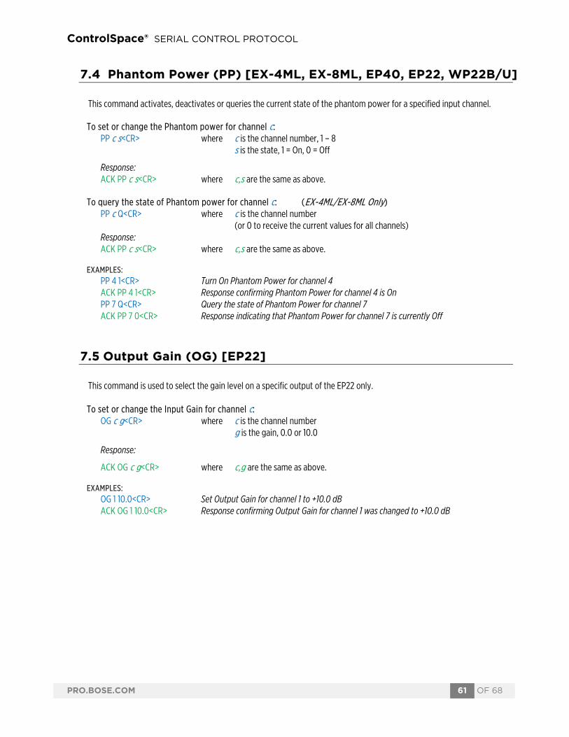
ControlSpace® SERIAL CONTROL PROTOCOL
PRO.BOSE.COM 61 OF 68
7.4 Phantom Power (PP) [EX-4ML, EX-8ML, EP40, EP22, WP22B/U] This command activates, deactivates or queries the current state of the phantom power for a specified input channel. To set or change the Phantom power for channel c:
PP c s<CR> where c is the channel number, 1 – 8 s is the state, 1 = On, 0 = Off
Response: ACK PP c s<CR> where c,s are the same as above.
To query the state of Phantom power for channel c: (EX-4ML/EX-8ML Only) PP c Q<CR> where c is the channel number
(or 0 to receive the current values for all channels) Response: ACK PP c s<CR> where c,s are the same as above.
EXAMPLES: PP 4 1<CR> Turn On Phantom Power for channel 4 ACK PP 4 1<CR> Response confirming Phantom Power for channel 4 is On PP 7 Q<CR> Query the state of Phantom Power for channel 7 ACK PP 7 0<CR> Response indicating that Phantom Power for channel 7 is currently Off
7.5 Output Gain (OG) [EP22] This command is used to select the gain level on a specific output of the EP22 only. To set or change the Input Gain for channel c:
OG c g<CR> where c is the channel number g is the gain, 0.0 or 10.0
Response:
ACK OG c g<CR> where c,g are the same as above.
EXAMPLES: OG 1 10.0<CR> Set Output Gain for channel 1 to +10.0 dB ACK OG 1 10.0<CR> Response confirming Output Gain for channel 1 was changed to +10.0 dB

ControlSpace® SERIAL CONTROL PROTOCOL
PRO.BOSE.COM 62 OF 68
7.6 Read Signal Level (RSL) [EX-4ML, EX-8ML] This command queries the current signal levels for each of the available channels on the EX-4ML and EX-8ML devices only. The EX-8ML will return 8 values and the EX-4ML will return 4 values. To query the current signal levels:
RSL<CR> Response: ACK RSL 1 2 3 4 5 6 7 8<CR> where 1-8 are the current signal levels for each channel,
Possible values are -99, -40, -9, -3 dB EXAMPLES:
RSL<CR> Command requesting current signal levels ACK RSL -99 -3 -9 -40<CR> Response indicating ch1 is off, ch2 is >= -3dB, ch3 is >= -9dB and < -3dB and ch4
is >= -40dB and < -9dB
7.7 Read/Write Logic Output (RLO/WLO) [EX-4ML, EX-8ML] These commands allow each of the logic outputs of the EX-4ML or EX-8ML devices to be set or queried. The EX-4ML has 8 logic outputs (2 per channel) and the EX-8ML has 16 logic outputs.
To set or change the state of logic output p:
WLO p s<CR> where p is the logic output, 1 – 16 (for EX-8ML), 1 – 8 (for EX-4ML) s is the state, 1 = On, 0 = Off
Response: ACK WLO p s<CR> where p,s are the same as above.
To query the state of logic output p: RLO p<CR> where p is the logic output, 1 – 16 (for EX-8ML), 1 – 8 (for EX-4ML) (or 0 to receive the current setting for all outputs) Response: ACK RLO p s<CR> where p is the logic output, 1 – 16 (for EX-8ML), 1 – 8 (for EX-4ML) s is the state, 1 = On, 0 = Off
EXAMPLES: WLO 4 0<CR> Turn off logic output 4 ACK WLO 4 0<CR> Response confirming logic output 4 is Off RLO 2<CR> Query the state of logic output 2 ACK WLO 2 1<CR> Response indicating logic output pin 2 is On RL0 0<CR> Query the state of all logic outputs ACK RLO 0 0<CR> Response acknowledging the query first, followed by: ACK RLI 1 0<CR> Response confirming logic output 1 is Off ACK RLI 2 0<CR> Response confirming logic output 2 is Off ACK RLI 3 0<CR> Response confirming logic output 3 is Off … (response for each channel) ACK RLI 8 1<CR> Response confirming logic output 8 is On

ControlSpace® SERIAL CONTROL PROTOCOL
PRO.BOSE.COM 63 OF 68
7.8 Read Logic Input (RLI) [EX-4ML, EX-8ML] This command allows each of the logic inputs of the EX-4ML and EX-8ML to be queried. The EX-4ML has 4 logic inputs (one per channel) and the EX-8ML has 8 logic inputs. Note: This is the de-bounced value, not an instantaneous reading of the pin. To query the state of a logic input p:
RLI p<CR> where p is the logic input, 1 – 8 (for EX-8ML), 1 – 4 (for EX-4ML) (or 0 to receive the current state of all inputs) Response: ACK RLI p s<CR> where p is the logic input, 1 – 8 (for EX-8ML), 1 – 4 (for EX-4ML)
s is the state, On = 1, Off = 0
EXAMPLES:
RLI 7<CR> Query the state of the logic input 7 ACK RLI 7 1<CR> Response confirming logic input 7 is On RLI 0<CR> Query the state of all logic inputs ACK RLI 0 0<CR> Response acknowledging the query first, followed by: ACK RLI 1 0<CR> Response confirming logic input 1 is Off ACK RLI 2 1<CR> Response confirming logic input 2 is On ACK RLI 3 0<CR> Response confirming logic input 3 is Off ACK RLI 4 1<CR> Response confirming logic input 1 is On
7.9 Set Logic Event (EVNT) [EX-4ML, EX-8ML] This command configures the EX-4ML or EX-8ML to automatically send an event notification when the state of one of its logic inputs changes. Events can be set to occur on rising edge (RISE), falling edge (FALL), BOTH or OFF. The event notification will be sent as a UDP packet to the IP address/port specified by the SASIP command. This can remove the need to constantly poll for the state of logic inputs. This mechanism is used when EX endpoints are paired with EX processors and making changes to these settings could cause unexpected side-effects in that scenario. To set or change event notification for logic input p:
EVNT p e<CR> where p is the logic input, 1 – 8 (for EX-8ML), 1 – 4 (for EX-4ML) e is the event type, RISE, FALL, BOTH or OFF Response: ACK EVNT p e<CR> where p,e are the same as above.
EXAMPLES: EVNT 9 BOTH<CR> Turn on event notification for logic input 9, for both rising and falling edge ACK EVNT 9 BOTH<CR> Response confirming event notification for logic input 9 EVNT 5 FALL<CR> Turn on event notification when logic input 5 turns Off ACK EVNT 5 FALL<CR> Response confirming event notification for logic input 5
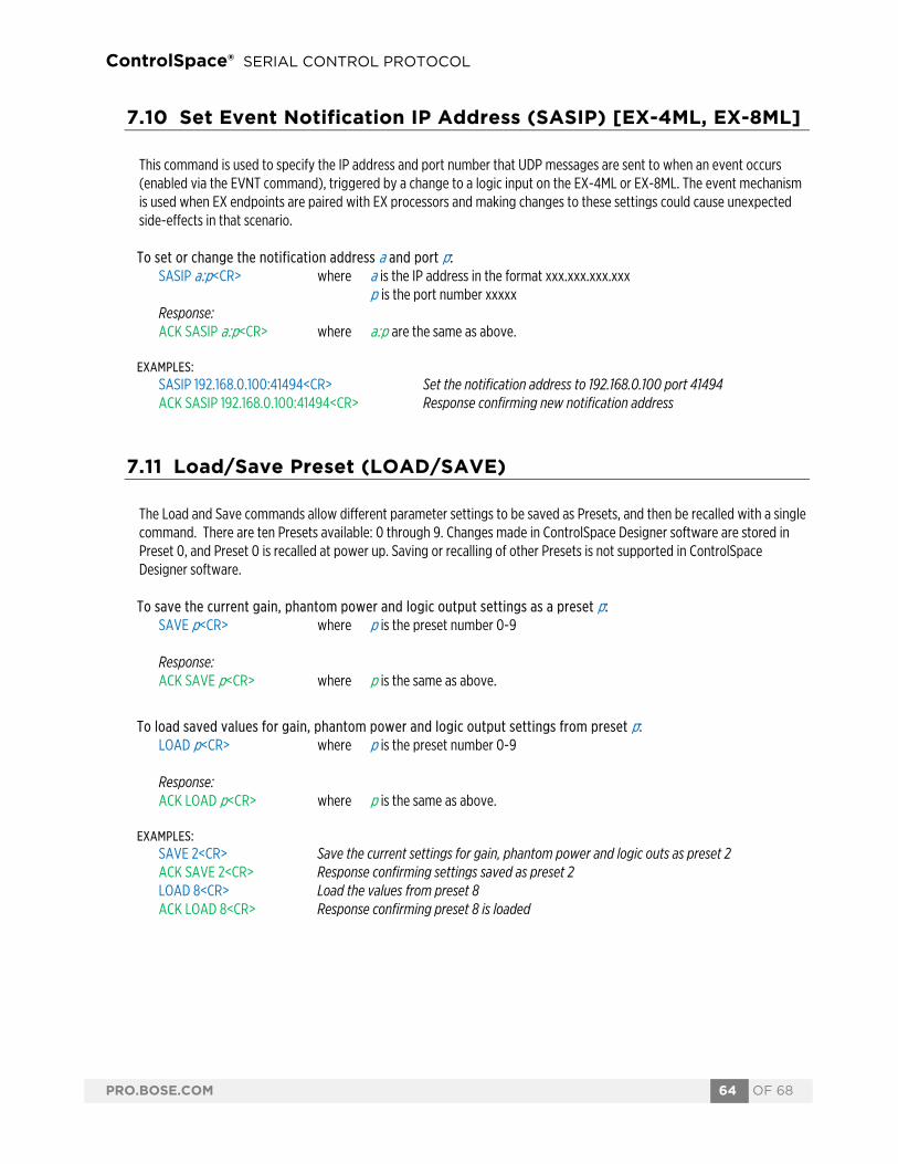
ControlSpace® SERIAL CONTROL PROTOCOL
PRO.BOSE.COM 64 OF 68
7.10 Set Event Notification IP Address (SASIP) [EX-4ML, EX-8ML] This command is used to specify the IP address and port number that UDP messages are sent to when an event occurs (enabled via the EVNT command), triggered by a change to a logic input on the EX-4ML or EX-8ML. The event mechanism is used when EX endpoints are paired with EX processors and making changes to these settings could cause unexpected side-effects in that scenario.
To set or change the notification address a and port p:
SASIP a:p<CR> where a is the IP address in the format xxx.xxx.xxx.xxx p is the port number xxxxx Response: ACK SASIP a:p<CR> where a:p are the same as above.
EXAMPLES:
SASIP 192.168.0.100:41494<CR> Set the notification address to 192.168.0.100 port 41494 ACK SASIP 192.168.0.100:41494<CR> Response confirming new notification address
7.11 Load/Save Preset (LOAD/SAVE) The Load and Save commands allow different parameter settings to be saved as Presets, and then be recalled with a single command. There are ten Presets available: 0 through 9. Changes made in ControlSpace Designer software are stored in Preset 0, and Preset 0 is recalled at power up. Saving or recalling of other Presets is not supported in ControlSpace Designer software.
To save the current gain, phantom power and logic output settings as a preset p:
SAVE p<CR> where p is the preset number 0-9 Response: ACK SAVE p<CR> where p is the same as above.
To load saved values for gain, phantom power and logic output settings from preset p: LOAD p<CR> where p is the preset number 0-9 Response: ACK LOAD p<CR> where p is the same as above.
EXAMPLES: SAVE 2<CR> Save the current settings for gain, phantom power and logic outs as preset 2 ACK SAVE 2<CR> Response confirming settings saved as preset 2 LOAD 8<CR> Load the values from preset 8 ACK LOAD 8<CR> Response confirming preset 8 is loaded

ControlSpace® SERIAL CONTROL PROTOCOL
PRO.BOSE.COM 65 OF 68
7.12 Query Audio Settings (QUERY) The Query command allows remote systems to get a snapshot of the current state of the device with a single command. When a Query command is sent, the response includes the state of all the audio parameters for the device. The response will be different for each model per the controls available, and each setting is separated with a space. To query the current settings for all audio parameters:
QUERY<CR> Response: ACK QUERY IG1=0.0 IG2=0.0 IG3=0.0 IG4=0.0 IG5=0.0 IG6=0.0 IG7=0.0 IG8=0.0 PP1=OFF PP2=OFF PP3=OFF PP4=OFF PP5=OFF PP6=OFF PP7=OFF PP8=OFF ID=OFF <CR>
7.13 Restore Factory Defaults (DEFAULTS) The Defaults command forces the device to return to factory settings. Where applicable, Input and Output gains are set to 0.0, Phantom power is turned Off for all channels and Logic outputs are Off for all channels. These settings are also stored to Preset 0 for use at power-up. Settings in other Presets remain unaffected. To reset the endpoint settings back to their defaults:
DEFAULTS<CR> Response: ACK DEFAULTS<CR>
7.14 Query Firmware Version (VERSION) This command queries the current firmware version loaded on endpoint devices only. To query the firmware version for the device:
VERSION<CR> Response: ACK VERSION x.x<CR>
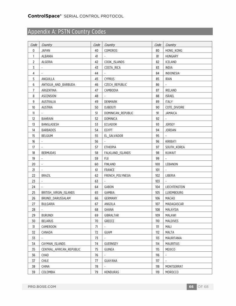
ControlSpace® SERIAL CONTROL PROTOCOL
PRO.BOSE.COM 66 OF 68
Appendix A: PSTN Country Codes
Code Country Code Country Code Country
0 JAPAN 40 COMOROS 80 HONG_KONG
1 ALBANIA 41 -CONGO_REPUBLIC 81 HUNGARY
2 ALGERIA 42 COOK_ISLANDS 82 ICELAND
3 -AMERICAN_SAMOA 43 COSTA_RICA 83 INDIA
4 -GERMANY 44 -CUBA 84 INDONESIA
5 ANGUILLA 45 CYPRUS 85 IRAN
6 ANTIGUA_AND_BARBUDA 46 CZECH_REPUBLIC 86 -IRAQ
7 ARGENTINA 47 CAMBODIA 87 IRELAND
8 ASCENSION 48 -NORTH_KOREA 88 ISRAEL
9 AUSTRALIA 49 DENMARK 89 ITALY
10 AUSTRIA 50 DJIBOUTI 90 COTE_DIVOIRE
11 -BAHAMAS 51 DOMINICAN_REPUBLIC 91 JAMAICA
12 BAHRAIN 52 DOMINICA 92 -AFGHANISTAN
13 BANGLADESH 53 ECUADOR 93 JERSEY
14 BARBADOS 54 EGYPT 94 JORDAN
15 BELGIUM 55 EL_SALVADOR 95 -KENYA
16 -BELIZE 56 -EQUATORIAL_GUINEA 96 KIRIBATI
17 -BENIN 57 ETHIOPIA 97 SOUTH_KOREA
18 BERMUDAS 58 FALKLAND_ISLANDS 98 KUWAIT
19 -BHUTAN 59 FIJI 99 -LAO
20 -BOLIVIA 60 FINLAND 100 LEBANON
21 -BOTSWANA 61 FRANCE 101 -LESOTHO
22 BRAZIL 62 FRENCH_POLYNESIA 102 LIBERIA
23 -BRITISH_ANTARCTIC_TERRITORY 63 -AVAILABLE 103 -LIBYA
24 -BRITISH_INDIAN_OCEAN_TERITORY 64 GABON 104 LIECHTENSTEIN
25 BRITISH_VIRGIN_ISLANDS 65 GAMBIA 105 LUXEMBOURG
26 BRUNEI_DARUSSALAM 66 GERMANY 106 MACAO
27 BULGARIA 67 ANGOLA 107 MADAGASCAR
28 -MYANMAR 68 GHANA 108 MALAYSIA
29 BURUNDI 69 GIBRALTAR 109 MALAWI
30 BELARUS 70 GREECE 110 MALDIVES
31 CAMEROON 71 -GRENADA 111 MALI
32 CANADA 72 GUAM 112 MALTA
33 -CAPE_VERDE 73 -GUATEMALA 113 MAURITANIA
34 CAYMAN_ISLANDS 74 GUERNSEY 114 MAURITIUS
35 CENTRAL_AFRICAN_REPUBLIC 75 GUINEA 115 MEXICO
36 CHAD 76 -GUINEA_BISSAU 116 -MONACO
37 CHILE 77 GUAYANA 117 -MONGOLIA
38 CHINA 78 -HAITI 118 MONTSERRAT
39 COLOMBIA 79 HONDURAS 119 MOROCCO

ControlSpace® SERIAL CONTROL PROTOCOL
PRO.BOSE.COM 67 OF 68
Code Country Code Country Code Country
120 MOZAMBIQUE 160 SPAIN 200 -AVAILABLE
121 -NAURU 161 SRI_LANKA -
122 -NEPAL 162 -SUDAN -
123 NETHERLANDS 163 SURINAME 240 CROATIA
124 -NETHERLANDS_ANTILLES 164 SWAZILAND 241 KAZAKHSTAN
125 NEW_CALEDONIA 165 SWEDEN 242 -AVAILABLE
126 NEW_ZEALAND 166 SWITZERLAND 243 -AVAILABLE
127 -NICARAGUA 167 SYRIA 244 -AVAILABLE
128 NIGER 168 -TANZANIA 245 -AVAILABLE
129 NIGERIA 169 THAILAND 246 -AVAILABLE
130 NORWAY 170 -TOGO 247 -AVAILABLE
131 OMAN 171 -TONGA 248 LATVIA
132 PAKISTAN 172 TRINIDAD_AND_TOBAGO 249 ESTONIA
133 PANAMA 173 TUNISIA 250 US_VIRGIN_ISLANDS
134 PAPUA_NEW_GUINEA 174 TURKEY 251 -AVAILABLE
135 PARAGUAY 175 TURKS_AND_CAICOS_ISLANDS 252 -AVAILABLE
136 PERU 176 TUVALU 253 UNIVERSAL
137 PHILIPPINES 177 UGANDA 254 TAIWAN
138 POLAND 178 UKRAINE
139 PORTUGAL 179 UNITED_ARAB_EMIRATES
140 PUERTO_RICO 180 UNITED_KINGDOM
141 QATAR 181 UNITED_STATES
142 ROMANIA 182 BURKINA_FASO
143 RWANDA 183 URUGUAY
144 SAINT_KITTS_AND_NEVIS 184 RUSSIA
145 -SAINT_CROIX 185 VANUATU
146 SAINT_HELENA_AND_ASCENSION 186 -VATICAN_CITY_STATE
147 SAINT_LUCIA 187 VENEZUELA
148 -SAN_MARINO 188 VIETNAM
149 SAINT_THOMAS 189 -WALLIS_AND_FUTUNA
150 SAO_TOME_AND_PRINCIPE 190 -SAMOA
151 SAINT_VICENT_AND_THE_GRENADINES 191 YEMEN
152 SAUDI_ARABIA 192 -YEMEN
153 SENEGAL 193 SERBIA
154 SEYCHELLES 194 -CONGO_DEMOCRATIC_REPUBLIC
155 SIERRA_LEONE 195 ZAMBIA
156 SINGAPORE 196 -ZIMBABWE
157 SOLOMON_ISLANDS 197 SLOVAKIA
158 -SOMALIA 198 SLOVENIA
159 SOUTH_AFRICA 199 LITHUANIA

ControlSpace® SERIAL CONTROL PROTOCOL
PRO.BOSE.COM 68 OF 68
CobraNet is a registered trademark of Cirrus Logic, Inc. Windows is a registered trademark of Microsoft, Inc.
Dante is a registered trademark of Audinate, Inc. All other trademarks are the property of their respective owners.

![ControlSpace Serial Control Protocol v5 · 2020-03-24 · 6.1 ESP/EXModuleIndices 22 6.1.1 INPUTModule 22 6.1.2 OUTPUTModule 22 6.1.3 ESPLinkModule[ESPOnly] 23 6.1.4 AMPLinkModule](https://img.pdfslide.us/doc/110x75/5f8add49fecfff5d5a5db228/controlspace-serial-control-protocol-v5-2020-03-24-61-espexmoduleindices-22.jpg)


![ControlSpace Serial Control Protocol v5 · 6.1 ESP/EXModuleIndices 22 6.1.1 INPUTModule 22 6.1.2 OUTPUTModule 23 6.1.3 ESPLinkModule[ESPOnly] 23 6.1.4 AMPLinkModule 24](https://img.pdfslide.us/doc/110x75/5f07e9167e708231d41f5f20/controlspace-serial-control-protocol-v5-61-espexmoduleindices-22-611-inputmodule.jpg)