Embed Size (px)
Citation preview

48/50HJ004---014, 50HJQ004---012, 48/50HE003---00650HEQ003---006, 48/50TM004---014RTU---MP (Multi---Protocol) 2.x ControllerBACnet, Modbus, Johnson N2, and LonWorks
Controls, Start---Up, Operation andTroubleshooting Instructions
TABLE OF CONTENTSSAFETY CONSIDERATIONS 2. . . . . . . . . . . . . . . . . . . . . . . . .
GENERAL 2. . . . . . . . . . . . . . . . . . . . . . . . . . . . . . . . . . . . . . . . .
ACCESSORY/SENSOR INSTALLATION 2. . . . . . . . . . . . . . . .
Field--Supplied Hardware 2. . . . . . . . . . . . . . . . . . . . . . . . . . . .
User Interface 2. . . . . . . . . . . . . . . . . . . . . . . . . . . . . . . . . . . . . .
Install Sensors 5. . . . . . . . . . . . . . . . . . . . . . . . . . . . . . . . . . . . .
Space Temperature (SPT) Sensor Installation 5. . . . . . . . . . . .
Indoor Air Quality CO2 Sensor Installation (IAQ) 7. . . . . . . .
Outdoor Air Quality CO2 Sensor Installation (OAQ) 7. . . . . .
Outdoor Air Temperature Sensor 10. . . . . . . . . . . . . . . . . . . .
Space Relative Humidity Sensor (SPRH) 12. . . . . . . . . . . . . .
Outdoor Air Relative Humidity Sensor (OARH) 12. . . . . . . .
Connect Discrete Inputs 13. . . . . . . . . . . . . . . . . . . . . . . . . . . . .
Humidistat 13. . . . . . . . . . . . . . . . . . . . . . . . . . . . . . . . . . . . .
Fire Shutdown 13. . . . . . . . . . . . . . . . . . . . . . . . . . . . . . . . . .
Filter Status 13. . . . . . . . . . . . . . . . . . . . . . . . . . . . . . . . . . . . .
Fan Status 13. . . . . . . . . . . . . . . . . . . . . . . . . . . . . . . . . . . . . .
Remote Occupancy 13. . . . . . . . . . . . . . . . . . . . . . . . . . . . . . .
Enthalpy Switch/Receiver 13. . . . . . . . . . . . . . . . . . . . . . . . . .
Outdoor Enthalpy Control 14. . . . . . . . . . . . . . . . . . . . . . . . .
Differential Enthalpy Control 14. . . . . . . . . . . . . . . . . . . . . . .
Enthalpy Switch/Receiver Jumper Settings 15. . . . . . . . . . . . .
Enthalpy Sensor Jumper Settings 15. . . . . . . . . . . . . . . . . . . .
Communication Wiring--Protocols 15. . . . . . . . . . . . . . . . . . . . .
General 15. . . . . . . . . . . . . . . . . . . . . . . . . . . . . . . . . . . . . . . .
BACnet MS/TP 15. . . . . . . . . . . . . . . . . . . . . . . . . . . . . . . . .
Modbus 16. . . . . . . . . . . . . . . . . . . . . . . . . . . . . . . . . . . . . . .
Johnson N2 16. . . . . . . . . . . . . . . . . . . . . . . . . . . . . . . . . . . . .
LonWorks 16. . . . . . . . . . . . . . . . . . . . . . . . . . . . . . . . . . . . . .
Local Access 16. . . . . . . . . . . . . . . . . . . . . . . . . . . . . . . . . . . .
START--UP 17. . . . . . . . . . . . . . . . . . . . . . . . . . . . . . . . . . . . . . . .
Field Service Test 17. . . . . . . . . . . . . . . . . . . . . . . . . . . . . . . . . .
Configuration 17. . . . . . . . . . . . . . . . . . . . . . . . . . . . . . . . . . . .
Unit 17. . . . . . . . . . . . . . . . . . . . . . . . . . . . . . . . . . . . . . . . . .
Cooling 17. . . . . . . . . . . . . . . . . . . . . . . . . . . . . . . . . . . . . . . .
Heating 18. . . . . . . . . . . . . . . . . . . . . . . . . . . . . . . . . . . . . . . .
Inputs 18. . . . . . . . . . . . . . . . . . . . . . . . . . . . . . . . . . . . . . . . .
Economizer 19. . . . . . . . . . . . . . . . . . . . . . . . . . . . . . . . . . . .
IAQ 19. . . . . . . . . . . . . . . . . . . . . . . . . . . . . . . . . . . . . . . . . .
Clock Set 19. . . . . . . . . . . . . . . . . . . . . . . . . . . . . . . . . . . . . .
UserPW 19. . . . . . . . . . . . . . . . . . . . . . . . . . . . . . . . . . . . . . .
Sequence of Operation 19. . . . . . . . . . . . . . . . . . . . . . . . . . . . . .
Scheduling 19. . . . . . . . . . . . . . . . . . . . . . . . . . . . . . . . . . . . .
Indoor Fan 20. . . . . . . . . . . . . . . . . . . . . . . . . . . . . . . . . . . . .
Cooling 20. . . . . . . . . . . . . . . . . . . . . . . . . . . . . . . . . . . . . . . .
Economizer 20. . . . . . . . . . . . . . . . . . . . . . . . . . . . . . . . . . . .
Power Exhaust 21. . . . . . . . . . . . . . . . . . . . . . . . . . . . . . . . . .
Heating 21. . . . . . . . . . . . . . . . . . . . . . . . . . . . . . . . . . . . . . . .
Indoor Air Quality 21. . . . . . . . . . . . . . . . . . . . . . . . . . . . . . .
Dehumidification 21. . . . . . . . . . . . . . . . . . . . . . . . . . . . . . . .
Demand Limit 22. . . . . . . . . . . . . . . . . . . . . . . . . . . . . . . . . .
TROUBLESHOOTING 22. . . . . . . . . . . . . . . . . . . . . . . . . . . . . .
General 22. . . . . . . . . . . . . . . . . . . . . . . . . . . . . . . . . . . . . . . . .
Communication LEDs 22. . . . . . . . . . . . . . . . . . . . . . . . . . . . . .
Alarms 24. . . . . . . . . . . . . . . . . . . . . . . . . . . . . . . . . . . . . . . . . .
Third Party Networking 24. . . . . . . . . . . . . . . . . . . . . . . . . . . . .
APPENDIX A: DISPLAY TABLES 26--32. . . . . . . . . . . . . . . . .

2
SAFETY CONSIDERATIONSInstallation and servicing of air-conditioning equipment can behazardous due to system pressure and electrical components. Onlytrained and qualified service personnel should install, repair, orservice air-conditioning equipment.
Untrained personnel can perform the basic maintenance functionsof cleaning coils and filters and replacing filters. All otheroperations should be performed by trained service personnel.When working on air-conditioning equipment, observe precautionsin the literature, tags and labels attached to the unit, and othersafety precautions that may apply.
Follow all safety codes. Wear safety glasses and work gloves.
Recognize safety information. This is the safety--alert symbol .When you see this symbol on the unit and in instructions ormanuals, be alert to the potential for personal injury.
Understand the signal words DANGER, WARNING, andCAUTION. These words are used with the safety--alert symbol.DANGER identifies the most serious hazards which will result insevere personal injury or death. WARNING signifies a hazardwhich could result in personal injury or death. CAUTION is usedto identify unsafe practices which may result in minor personalinjury or product and property damage. NOTE is used to highlightsuggestions which will result in enhanced installation, reliability, oroperation.
ELECTRICAL SHOCK HAZARD
Failure to follow this warning could cause personalinjury, death and/or equipment damage.
Disconnect all power to the unit before performingmaintenance or service. Unit may automatically start ifpower is not disconnected.
! WARNING
GENERALThe RTU--MP controller is an integrated component of the Carrierrooftop unit. Its internal application programming providesoptimum performance and energy efficiency. RTU--MP enablesthe unit to run in 100% stand--alone control mode or it cancommunicate to the Building Automation System (BAS).On--board DIP switches allow you to select your protocol (andbaud rate) of choice among the four most popular protocols in usetoday: BACnet, Modbus, Johnson N2 and LonWorks. (See Fig.19.)
Carrier’s diagnostic display tools such as BACview6 Handheld orVirtual BACview can be used with the RTU--MP controller.Access is available via a 5--pin J12 access port.
ACCESSORY/SENSOR INSTALLATIONField accessories for the RTU--MP include a room sensor,communication wiring, humidistat or relative humidity sensor andindoor and outdoor air quality. All field control wiring thatconnects to the RTU--MP must be routed through the raceway builtinto the corner post as shown in Fig. 2. The raceway provides theUL required clearance between high--and low--voltage wiring.Pass the control wires through the hole provided in the corner post,then feed the wires thorough the raceway to the RTU--MP.Connect the wires to the removable Phoenix connectors and thenreconnect the connectors to the board.
NOTE: For rooftop unit installation, refer to base unit installationinstructions.
ELECTRICAL SHOCK HAZARD
Failure to follow this warning could cause personalinjury, death and/or equipment damage.
Disconnect electrical power and use lock--out tagsbefore wiring the RTU--MP controller.
! WARNING
Field--Supplied HardwareThe RTU--MP controller is configurable with the followingfield-supplied sensors:
NOTE: Supply air temperature sensor (33ZCSENSAT) isfactory--installed.S space temperature sensor 33ZCT55SPT, 33ZCT56SPT, or
33ZCT59SPT
S indoor air quality sensor (33ZCSENCO2, 33ZCT55CO2,
33ZCT56CO2, ) required only for demand control ventilation.
A dedicated 24-vac transformer is required.
S outdoor air quality sensor (33ZCTSENCO2) required only for
demand control ventilation
S CO2 aspirator box (C33ZCCASPCO2) required for CO2 return
duct/outside air applications
S outdoor air temperature sensor (33ZCSENOAT)
(factory supplied with Economizer)
S outdoor air enthalpy switch (33CSENTHSW)
S return air enthalpy sensor (33CSENTSEN)
S space relative humidity sensor (33ZCSENSRH--01)
S outdoor relative humidity (332CSENORH--01)
S humidistat (TSTATCCPLH01--B)
S filter status switch (33CSFS----01)
S fan status switch (33CSAS----01 or field supplied rated at 24
VAC dry contact CRSTATUS001A00)
User InterfaceS BACview6 Handheld
S Virtual BACview
For specific details about sensors, refer to the literature suppliedwith the sensor.

3
C07467
Fig. 1 -- RTU--MP Control Module
RTU--MP
4
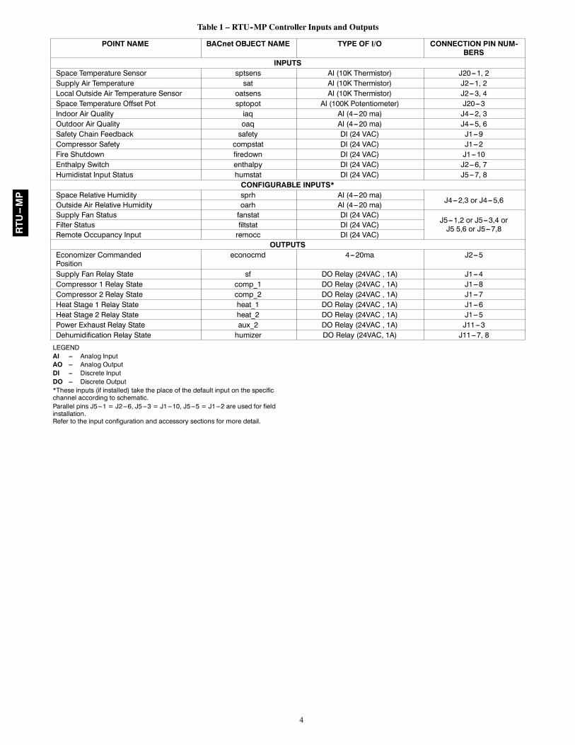
Table 1 – RTU--MP Controller Inputs and Outputs
POINT NAME BACnet OBJECT NAME TYPE OF I/O CONNECTION PIN NUM-BERS
INPUTSSpace Temperature Sensor sptsens AI (10K Thermistor) J20---1, 2Supply Air Temperature sat AI (10K Thermistor) J2---1, 2Local Outside Air Temperature Sensor oatsens AI (10K Thermistor) J2---3, 4Space Temperature Offset Pot sptopot AI (100K Potentiometer) J20---3Indoor Air Quality iaq AI (4---20 ma) J4---2, 3Outdoor Air Quality oaq AI (4---20 ma) J4---5, 6Safety Chain Feedback safety DI (24 VAC) J1---9Compressor Safety compstat DI (24 VAC) J1---2Fire Shutdown firedown DI (24 VAC) J1---10Enthalpy Switch enthalpy DI (24 VAC) J2---6, 7Humidistat Input Status humstat DI (24 VAC) J5---7, 8
CONFIGURABLE INPUTS*Space Relative Humidity sprh AI (4---20 ma)
J4---2,3 or J4---5,6Outside Air Relative Humidity oarh AI (4---20 ma)Supply Fan Status fanstat DI (24 VAC)
J5---1,2 or J5---3,4 orJ5 5,6 or J5---7,8Filter Status filtstat DI (24 VAC)
Remote Occupancy Input remocc DI (24 VAC)OUTPUTS
Economizer CommandedPosition
econocmd 4---20ma J2---5
Supply Fan Relay State sf DO Relay (24VAC , 1A) J1---4Compressor 1 Relay State comp_1 DO Relay (24VAC , 1A) J1---8Compressor 2 Relay State comp_2 DO Relay (24VAC , 1A) J1---7Heat Stage 1 Relay State heat_1 DO Relay (24VAC , 1A) J1---6Heat Stage 2 Relay State heat_2 DO Relay (24VAC , 1A) J1---5Power Exhaust Relay State aux_2 DO Relay (24VAC , 1A) J11---3Dehumidification Relay State humizer DO Relay (24VAC, 1A) J11---7, 8
LEGENDAI --- Analog InputAO --- Analog OutputDI --- Discrete InputDO --- Discrete Output*These inputs (if installed) take the place of the default input on the specificchannel according to schematic.Parallel pins J5---1 = J2---6, J5---3 = J1---10, J5---5 = J1---2 are used for fieldinstallation.Refer to the input configuration and accessory sections for more detail.
RTU--MP

5
Field connection terminals are removablefor easy wiring
Low voltagefield wiringconduit
Low voltage divider
Fieldwiring
Temporarycomputerconnection
C07164
Fig. 2 -- Field Control Wiring
Install SensorsThe RTU--MP controller requires the installation of a spacetemperature sensor and the operation of a supply air sensor (factoryinstalled). An outdoor air sensor is required for economizeroperation. Two analog sensors can be installed and configured,which can consist of an indoor air quality, outdoor air quality,space relative humidity, or outdoor relative humidity sensor. SeeFig. 1, Table 1, and Fig. 7 for wiring and pin reference. Refer tothe instructions supplied with individual sensors for additionalinformation.
NOTE: All sensors are field--installed accessories except wherenoted.
Space Temperature (SPT) Sensor InstallationThere are three types of SPT sensors available from Carrier: the33ZCT55SPT space temperature sensor with timed overridebutton, the 33ZCT56SPT space temperature sensor with timedoverride button and set point adjustment, and the 33ZCT59SPTspace temperature sensor with LCD screen, override button, and setpoint adjustment.
The space temperature sensors are used to measure the buildinginterior temperature. Sensors should be located on an interiorbuilding wall. The sensor wall plate accommodates the NEMA(National Electrical Manufacturers Association) standard 2 x 4junction box. The sensor can be mounted directly on the wallsurface if acceptable by local codes.
Do not mount the sensor in drafty locations such as near airconditioning or heating ducts, over heat sources such as baseboardheaters, radiators, or directly above wall-mounted lightingdimmers. Do not mount the sensor near a window which may beopened, near a wall corner, or a door. Do not mount the sensor indirect sunlight. Sensors mounted in these areas will haveinaccurate and erratic sensor readings.
The sensor should be mounted approximately 5 ft from the floor,in an area representing the average temperature in the space. Allowat least 4 ft between the sensor and any corner and mount thesensor at least 2 ft from an open doorway. The SPT sensor wiresare to be connected to terminals in the unit main control board.
RTU--MP

6
2 3 4 5 61
SW1
SEN
BRN (GND)BLU (SPT)
SENSOR WIRING
C07130
Fig. 3 -- Space Temperature SensorTypical Wiring (33ZCT55SPT)
2 3 4 5 61
SW1
SEN SET
Cool Warm
BRN (GND)BLU (SPT)
SENSOR WIRING
JUMPERTERMINALSAS SHOWN
BLK(T56)
C07131
Fig. 4 -- Space Temperature SensorTypical Wiring (33ZCT56SPT)
OR SET SEN
OPB COM- PWR+
BLU (SPT)
BLK (STO)
24 VAC
SENSORWIRING
POWERWIRING
BRN (COM)
NOTE: Must use a separate isolated transformer.
C07132
Fig. 5 -- Space Temperature SensorTypical Wiring (33ZCT59SPT)
Install the sensor as follows:
1. Locate the two Allen type screws at the bottom of the sen-sor.
2. Turn the two screws clockwise to release the cover from thesensor wall mounting plate.
3. Lift the cover from the bottom and then release it from thetop fasteners.
4. Feed the wires from the electrical box through the openingin the center of the sensor mounting plate.
5. Using two no. 6-32 x 1 mounting screws (provided with thesensor), secure the sensor to the electrical box.
NOTE: Sensor may also be mounted directly on the wall using 2plastic anchors and 2 sheet metal screws (field-supplied).
6. Use 20 gauge wire to connect the sensor to the controller.The wire is suitable for distances of up to 500 ft. Use athree-conductor shielded cable for the sensor and set pointadjustment connections. If the set point adjustment (slide-bar) is not required, then an unshielded, 18 or 20 gauge,two-conductor, twisted pair cable may be used.
7. Replace the cover by inserting the cover at the top of themounting plate first, then swing the cover down over thelower portion. Rotate the two Allen head screws counter-clockwise until the cover is secured to the mounting plateand locked in position.
NOTE: See Table 2 for thermistor resistance vs temperaturevalues.
RTU--MP

7
Table 2 – Thermistor Resistance vs Temperature Valuesfor Space Temperature Sensor, Supply Air
Temperature Sensor, and OutdoorAir Temperature Sensor
TEMP(C)
TEMP(F)
RESISTANCE(Ohms)
–40 –40 335,651–35 –31 242,195–30 –22 176,683–25 –13 130,243–20 –4 96,974–15 5 72,895–10 14 55,298–5 23 42,3150 32 32,6515 41 25,39510 50 19,90315 59 15,71420 68 12,49425 77 10,00030 86 8,05635 95 6,53040 104 5,32545 113 4,36750 122 3,60155 131 2,98560 140 2,48765 149 2,08270 158 1,752
Wiring the Space Temperature Sensor
To wire the sensor, perform the following (See Fig. 3, 4 and 5.):
1. Identify which cable is for the sensor wiring.
2. Strip back the jacket from the cables for at least 3 inches.Strip 1/4-in. of insulation from each conductor. Cut theshield and drain wire from the sensor end of the cable.
3. Connect the sensor cable as follows:
a. Connect one wire from the cable to (BLU) wire onJ20--1 analog connector on the controller. Connect theother end of the wire to the left terminal on the SENterminal block of the sensor.
b. Connect another wire from the cable to (BRN) J20--2analog connector on the controller. Connect the otherend of the wire to the remaining open terminal on theSEN terminal block. On the 33ZCT59SPT sensor, con-nect this cable to the 24-v COM terminal. A separate24-vac transformer is required for this sensor. (See Fig.5.)
c. On 33ZCT56SPT and 33ZCT59SPT sensors, connectthe remaining wire to the (BLK) SPTO on J20--3 con-nector on the controller. Connect the other end of thewire to the SET terminal on the sensor.
d. In the control box, install a no. 10 ring type crimp lugon the shield drain wire. Install this lug under themounting screw of the RTU--MP controller.
e. On 33ZCT56SPT sensors, install a jumper between thetwo center terminals (right SEN and left SET). (See Fig.4.)
NOTE: See Fig. 6 for space temperature sensor averaging.T55/56 Override button will no longer function when sensors areaveraged. Only Sensor 1 T56 STO input can be used.
Do not mount the sensor in direct sunlight. Inaccurate readingsmay result. Do not mount the sensor near the exhaust fromair-handling units or compressors, near leakage drafts of indoor air,or near shrubbery or trees, or under direct water runoff.
Indoor Air Quality CO2 Sensor Installation (IAQ)The indoor air quality sensor accessory monitors carbon dioxideCO2 levels. This information is used to monitor IAQ levels. Threetypes of sensors are provided. The wall sensor can be used tomonitor the conditioned air space. Sensors use infrared technologyto measure the levels of CO2 present in the air. The wall sensor isavailable with or without an LCD readout to display the CO2 levelin ppm.
The CO2 sensors are all factory set for a range of 0 to 2000 ppmand a linear mA output of 4 to 20. Refer to the instructionssupplied with the CO2 sensor for electrical requirements andterminal locations.
To accurately monitor the quality of the air in the conditioned airspace, locate the sensor near a return air grille (if present) so itsenses the concentration of CO2 leaving the space. The sensorshould be mounted in a location to avoid direct breath contact.
Do not mount the IAQ sensor in drafty areas such as near supplyducts, open windows, fans, or over heat sources. Allow at least 3 ftbetween the sensor and any corner. Avoid mounting the sensorwhere it is influenced by the supply air; the sensor gives inaccuratereadings if the supply air is blown directly onto the sensor or if thesupply air does not have a chance to mix with the room air before itis drawn into the return airstream.
Wiring the Indoor Air Quality Sensor
To wire the sensors after they are mounted in the conditioned airspace or outdoor location, see the instructions shipped with thesensors. For each sensor, use two 2-conductor 18 AWG (AmericanWire Gauge) twisted-pair cables (unshielded) to connect theseparate isolated 24 vac power source to the sensor and to connectthe sensor to the control board terminals. To connect the sensor tothe control, identify the positive (4 to 20 mA) and ground (SIGCOM) terminals on the sensor. Connect the 4-20 mA terminal toterminal IAQ (J4--2) and connect the SIG COM terminal toterminal GND (J4--3).
Combination Temperature and CO2 Sensor
If using a combination temperature and CO2 sensor(33ZCT55CO2 or 33ZCT56CO2), refer to the installationinstructions provided with the sensor. See Fig. 2 and 7 for wiring.
Outdoor Air Quality CO2 Sensor Installation (OAQ)The Outdoor Air CO2 sensor is designed to monitor carbondioxide (CO2) levels in the air and interface with the ventilationdamper in an HVAC system. The OAQ sensor is packaged with anoutdoor cover. (See Fig. 8 and 9.)
The outdoor air CO2 sensor must be placed in an area that isrepresentative of the outdoor air not affected by building exhaustair or vehicle exhaust.
RTU--MP

8
J201
2
RED
BLK
RED RED
BLK BLK
BLK
RED
BLK
RED
SENSOR 1 SENSOR 2 SENSOR 3 SENSOR 4
J20RED
BLK
RED
BLK
SENSOR 2SENSOR 1
RED
RED
BLK
SENSOR 3
SENSOR 4
BLK
BLK
RE
D
RED RED
BLK BLK
SENSOR 8 SENSOR 9
SENSOR 5
RED
BLK
SENSOR 6
SENSOR 7
BLK
RE
D
SPACE TEMPERATURE AVERAGING — 4 SENSOR APPLICATION
SPACE TEMPERATURE AVERAGING — 9 SENSOR APPLICATION
LEGEND
Factory Wiring
Field Wiring
1
2
C07133
Fig. 6 -- Space Temperature Averaging
RTU--MP

9
Eco
no
miz
er P
lug
Co
nn
ecti
on
LEGEND
------------FieldSuppliedWiring
_______FactoryWiring
FieldSuppliedDevice
C07147
C07148
ForSingleCom
pressorUnits(Non--H
eatPum
pType)
50H
J542
479
Rev.
4
C07171
ForAllOtherUnits
Fig.7
--RTU--M
PControllerWiring
RTU--MP

10
8 7 6 5 4 3 2 12 1
H G 24 VACOR
24 VDC
NC ALARMRELAYCONTACTS
COMNO }
0-10VDCSIG COM (J4-6)4-20mA (J4-5)
+
+-
+ -
C07134
Fig. 8 -- Indoor/Outdoor Air Quality (CO2) Sensor33ZCSENC02) -- Typical Wiring Diagram
COVER REMOVED SIDE VIEW
C07135
Fig. 9 -- Outdoor Air Quality Sensor Cover
Wiring the Outdoor Air CO2 Sensor
Power requirements are 18 to 36 VAC RMS 50/60 Hz; 18 to 42vdc polarity protected/dependent; and 70 mA average, 100 mApeak at 24 vdc. All system wiring must be in compliance with allapplicable local and national codes. A dedicated power supply isrequired for this sensor. A two-wire cable is required to wire thededicated power supply for the sensor. The two wires should beconnected to the power supply and terminals 1 and 2. To connectthe sensor to the control, identify the positive (4 to 20 mA) andground (SIG COM) terminals on the sensor. Connect the 4 to 20mA terminal OAQ terminal J4-5. Connect the SIG COM terminalto terminal GND (BRN) terminal J4--6. (See Fig. 7.)
Outdoor Air Temperature Sensor (Fig. 10--13)The OAT sensor is factory installed for units with an economizer.
The OAT sensor must be located properly. For outdoor locationsuse sensor 33ZCSENOAT. For duct mounting in the fresh airintake, use sensor 33ZCSENPAT. The sensor must be installedimmediately upstream from outdoor air damper where it willaccurately sense the temperature of the outdoor air entering themixing box. (See Fig. 10 and 11.) For applications withouteconomizer, the sensor may be located in the outdoor air--duct nearthe outdoor air intake (Fig. 10) or on the exterior of the building(Fig. 10). The thermistor has a range of –40_ to 245_F and aresistance of 10,000 ohms at 77_F.
If the sensor is to be mounted in the outdoor air duct, use the33ZCSENPAT sensor which has a 2 x 4-in. by 11/2-in. deepelectrical box. Remove the cover and enter the knockout from therear of the box. Install the sensor through the opening so that thesensor leads are inside the electrical box. Secure the sensor to theelectrical box using a field-supplied 1/2-in. conduit nut. Drill a1/2-in. hole in the outdoor air duct about a foot upstream of the
outdoor air damper. Apply a 1/4-in. bead of silicone type sealeraround the opening and install the sensor through the hole. Securethe electrical box to the duct using 2 field-supplied, No. 10 sheetmetal screws. (See Fig. 13.)
C07136
Fig. 10 -- Outdoor Air Temperature SensorInstallation -- Located on Building Wall
(P/N 33ZCSENOAT)
RETURNAIR
OAT
OUTDOORAIR
ROOF TOPUNIT
C07137
Fig. 11 -- OAT Sensor Installation in OutsideAir Duct (P/N 33ZCSENPAT)
RTU--MP

11
SINGLE-GANGALUMINUMBELL BOX
0.5000 IN.(12.7 mm) NPTTHREADEDCONDUITOPENINGS TYP.
GROUNDSCREW
4.9200 IN.(125.0 mm)
4.5625 IN.(115.9 mm)
2.8125 IN.(71.4 mm)
FOAM COVERGASKET
ALUMINUMCOVER
2.0000 IN.(50.8 mm)
C07138
Fig. 12 -- Outdoor Air Temperature Sensor (P/N 33ZCSENOAT)
LEGENDOA — Outdoor AirOAT — Outdoor Air Temperature
33ZCSENPAT SENSOR DUCT MOUNTED
C07139
Fig. 13 -- Outdoor Air Temperature Sensor Installation -- Located in Outdoor Air Duct (P/N 33ZCSENPAT)
RTU--MP

12
Space Relative Humidity Sensor (SPRH)The accessory space humidity sensor is installed on an interior wallto measure the relative humidity of the air within the occupiedspace.
The use of a standard 2 x 4--in. electrical box to accommodate thewiring is recommended for installation. The sensor can be mounteddirectly on the wall, if acceptable by local codes.
EQUIPMENT DAMAGE HAZARD
Failure to follow this caution may result in equipmentdamage.
Do NOT clean or touch the sensing element with chemicalsolvents as they can permanently damage the sensor.
DO NOT mount the sensor in drafty areas such as nearheating or air--conditioning ducts, open windows, fans, orover heat sources such as baseboard heaters, radiators, orwall--mounted light dimmers. Sensors mounted in thoseareas will produce inaccurate readings.
CAUTION!
If the sensor is installed directly on a wall surface, install thehumidity sensor using 2 screws and 2 hollow wall anchors(field--supplied). Do not over tighten screws. (See Fig. 14.)
The sensor must be mounted vertically on the wall. The Carrierlogo should be oriented correctly when the sensor is properlymounted.
Avoid corner locations. Allow at least 4 ft between the sensor andany corner. Airflow near corners tends to be reduced, resulting inerratic sensor readings. The sensor should be vertically mountedapproximately 5 ft up from the floor, beside the space temperaturesensor.
For wiring distances up to 500 feet, use a 3--conductor, 18 or 20AWG cable. A shielded cable can be used, although the shield isnot required. The shield must be removed from the sensor end ofthe cable if this cable is used.
The power for the sensor is provided by the RTU--MP control onterminal J4--4 Input 1 is used or J4--1 if Input 2 is used. To wire thesensor perform the following:
1. At the sensor, remove 4--in. of jacket from the cable. Strip1/4--in. of insulation from each conductor. Route the cablethrough the wire clearance opening in the center of thesensor. (See Fig. 14.)
2. Connect a field--supplied BLACK wire to the sensor screwterminal marked Vin.
3. Connect a field--supplied RED wire into the sensor screwterminal marked Io.
4. At the RTU--MP controller, route the cable away from highvoltage wiring and disconnect the power to preventaccidental shorting or grounding of wires when connectingthe sensor. Remove the J4 Molex female plug.
5. Connect the field--supplied RED wire from the sensor toJ4--5 if Input 1 is used or J4--2 if Input 2 is used.
6. Connect the field--supplied BLACK wire from the sensor toJ4--4 if Input 1 will be used of J4--1 if Input 2 will be used.
SW2
123456
ON
Io Vin Gnd Vo
MOUNTINGHOLES
WIRINGOPENING
a33-9141
Vin - J4 -1 or J4 -4 24VdcIo - J4 -2 or J4 -5 4 -20mA output
C07201
Fig. 14 -- Humidity Sensor Installation
Outdoor Air Relative Humidity Sensor (OARH)The outdoor air relative humidity sensor accessory monitorsmoisture levels in the atmosphere. This information is used todetermine whether the economizer (if installed) will open duringthe free cooling mode.
The RH transmitter should be mounted so that the unit is under aneave and protected from the elements and direct sunlight.
Install the sensor as follows:
1. Using two #8 x 3/4” self--tapping TEK mounting screwsincluded with the sensor, secure the sensor.
2. Remove the cover and install conduit connectors, watertightfittings, and or 1/2” vent plug.Note that the inner ring will knockout first and then theouter ring should be tapped in (1) or (2) locations with ascrewdriver before it can be peeled out. The cover will beconnected to the housing by the sensor leads.
3. Use two--conductor, 16--22 AWG twisted pair or shieldedcable to connect the sensor to the controller. All wiringshould be done in accordance with all Local and NationalElectrical Code guidelines.
NOTE: When using a shielded cable, be sure to connect only (1)end of the shield to ground at the controller. Connecting both endsof the Shield to Ground may cause a Ground Loop.
4. Place the cover onto the unit and gently turn until it is tight.Be careful not to apply too much pressure when tightening.
Wiring the Outdoor Air Relative Humidity Sensor
To wire the sensor, perform the following (See Fig. 15.):
1. Identify which cable is for the sensor wiring.
2. Strip back the jacket from the cable for at least 3 inches.Strip 1/4--in. of insulation from each conductor. Cut theshield and drain wire (if located) from the sensor end of thecable.
RTU--MP

13
Relative Humidity Sensor(Polarized Male Connector)
J4-1 or J4-4 + 24 VDC Supply Voltage
J4-2 or J4-5 (-) 4 to 20 mA Current Loop Outputto RTU-MP
4-20 VAC GND 0-5V mA or or VDC 0-10V
SPAN
ZERO
C07210
Fig. 15 -- Wiring Outdoor Air Relative Humidity Sensor
3. Connect the sensor cable as follows:
a. Connect one wire from the cable for the 24DC source toJ4--4 on Input 1 or J4--1 if Input 2 will be used.Connect the other end of the wire to VAC terminal onthe sensor.
b. Connect the other wire from the cable for the 4--20mAsignal to J4--5 on Input 1 or J4--2 if Input 2 will beused. Connect the other end of the wire to 4--20mAterminal on the sensor.
4. In the Control box, install a no. 10 ring type crimp lug onthe shield drain wire. Install this lug under the mountingscrew of the RTU--MP controller.
Connect Discrete InputsField installing a humidistat, smoke detector, filter and/or fan statusswitch, remote occupancy switch, and enthalpy to the RTU--MPcontroller is explained below. For other details, refer to Fig. 1 and7 for wiring and the configuration section for configuration.
HumidistatThe humidistat input is only provided on J5--7 as input 9. (SeeFig. 1.) The Humidistat Switch configuration,MENU→Config→Inputs→input 9, identifies it and the normallyopen or normally closed status of this input at high humidity.
J5--8 = 24 VAC source for dry contactJ5--7 = Signal input
Fire ShutdownThe fire shutdown input is provided for unit shutdown in responseto a fire alarm or smoke detector. The Fire Shutdown Switchconfiguration, MENU→Config→Inputs→input 5, identifies thenormally closed status of this input when there is no fire alarm.For 48/50 units without factory installed smoke detectors, a jumperis installed between TB4--5 and TB4--7. (See Fig. 7.)
When field installing smoke detectors:
TB4--5 = 24 VAC source for dry contactTB4--6 = Signal input
NOTE: The jumper must then be reinstalled across TB4--6 andTB4--7.
Filter StatusThe filter status accessory is a field--installed accessory. Thisaccessory detects plugged filters. When installing this accessory,the unit must be configured for filter status by settingMENU→Config→Inputs→input 3, 5, 8, or 9 to Filter Status andnormally open (N/O) or normally closed (N/C). Input 8 or 9 isrecommended for easy of installation. Refer to Fig. 1 and 7 forwire terminations at J5.
Fan StatusThe fan status accessory is a field--installed accessory. Thisaccessory detects when the indoor fan is blowing air. Wheninstalling this accessory, the unit must be configured for fan statusby setting MENU→Config→Inputs→input 3, 5, 8, or 9 to FanStatus and normally open (N/O) or normally closed (N/C). Input 8or 9 is recommended for easy of installation. Refer to Fig. 1 and 7for wire terminations at J5.
Remote OccupancyThe remote occupancy accessory is a field--installed accessory.This accessory overrides the unoccupied mode and puts the unit inoccupied mode. When installing this accessory, the unit must beconfigured for remote occupancy by settingMENU→Config→Inputs→input 3, 5, 8, or 9 to RemoteOccupancy and normally open (N/O) or normally closed (N/C).Also set MENU→Schedules→occupancy source to DI on/off.Input 8 or 9 is recommended for easy of installation. Refer to Fig.1 and 7 for wire terminations at J5.
Enthalpy Switch/ReceiverThe accessory enthalpy switch/receiver (33CSENTHSW) sensestemperature and humidity of the air surrounding the device andcalculates the enthalpy when used without an enthalpy sensor. Therelay is energized when enthalpy is high and de--energized whenenthalpy is low (based on ASHRAE 90.1 criteria). If an accessoryenthalpy sensor (33CSENTSEN) is attached to the return air sensorinput, then differential enthalpy is calculated. The relay isenergized when the enthalpy detected by the return air enthalpysensor is less than the enthalpy at the enthalpy switch/receiver. Therelay is de--energized when the enthalpy detected by the return airenthalpy sensor is greater than the enthalpy at the enthalpyswitch/receiver (differential enthalpy control). (See Fig. 16 and 17.)
RTU--MP

14
C07140
Fig. 16 -- Enthalpy Switch/Receiver Dimensions(33CSENTHSW)
C07141
Fig. 17 -- Enthalpy Sensor Dimensions(33CSENTSEN)
Outdoor Enthalpy ControlOutdoor enthalpy control requires only an enthalpy switch/receiver(33CSENTHSW). The enthalpy switch/receiver is mounted in theoutdoor air inlet and calculates outdoor air enthalpy. The enthalpyswitch/receiver energizes the relay output when the outdoorenthalpy is above 28 BTU/lb OR dry bulb temperature is above75_F and is de--energized when the outdoor enthalpy is below 27BTU/lb AND dry bulb temperature is below 74.5_F. The relayoutput is wired to the unit economizer which will open or closedepending on the output of the switch.
NOTE: The enthalpy calculation is done using an average altitudeof 1000 ft above sea level.
Mounting
Mount the enthalpy switch/receiver in a location where the outdoorair can be sampled (such as the outdoor air intake). The enthalpyswitch/receiver is not a NEMA 4 (National ElectricalManufacturers Association) enclosure and should be mounted in alocation that is not exposed to outdoor elements such as rain orsnow. Use two field-supplied no. 8 x 3/4-in. TEK screws. Insert thescrews through the holes in the sides of the enthalpyswitch/receiver.
Wiring
Carrier recommends the use of 18 to 22 AWG (American WireGauge) twisted pair or shielded cable for all wiring. Allconnections must be made with 1/4-in. female spade connectors.
A 24-vac source is required to power the enthalpy switch/receiver;as shown in Fig. 18, the RTU--MP board provides 24 vac on one ofthe two grey wires. Connect the GND and 24-vac terminals on theenthalpy switch/receiver to the unit ground--brown wires on thetransformer. On some applications, the power from the economizerharness can be used to power the enthalpy switch/receiver. Topower the enthalpy switch/receiver from the economizer harness,connect power of the enthalpy switch/receiver to the red and brownwires (1 and 4) on the economizer harness.
For connection to rooftop units with RTU--MP control, connect theLOW Enthalpy terminal on the enthalpy switch/receiver to the greywire connected to J2--6.
To determine that the correct grey wire was used, measure thevoltage on the wire with power applied to the unit. If 24--vac is notsensed, the correct wire is connected. The grey wire with 24--vacmeasured with power on to the unit is used for a dry contact typeswitch.
Differential Enthalpy Control (Fig. 18)Differential enthalpy control requires both an enthalpyswitch/receiver (33CSENTHSW) and an enthalpy sensor(33CSENTSEN). The enthalpy switch/receiver is mounted in theoutdoor air inlet and calculates outdoor air enthalpy. The enthalpysensor is mounted in the return airstream and calculates theenthalpy of the indoor air.
The enthalpy switch/receiver energizes the HI Enthalpy relayoutput when the outdoor enthalpy is greater than the indoorenthalpy. The LOW Enthalpy terminal is energized when theoutdoor enthalpy is lower than the indoor enthalpy. The relayoutput is wired to the unit economizer which will open or closedepending on the output of the switch.
NOTE: The enthalpy calculation is done using an average altitudeof 1000 ft above sea level.
Mounting
Mount the enthalpy switch/receiver in a location where the outdoorair can be sampled (such as the outdoor air intake). The enthalpyswitch/receiver is not a NEMA 4 enclosure and should be mountedin a location that is not exposed to outdoor elements such as rain,snow, or direct sunlight. Use two field-supplied no. 8 x 3/4-in. TEKscrews. Insert the screws through the holes in the sides of theenthalpy switch/receiver.
Mount the enthalpy sensor in a location where the indoor air can besampled (such as the return air duct). The enthalpy sensor is not aNEMA 4 enclosure and should be mounted in a location that is notexposed to outdoor elements such as rain or snow. Use twofield-supplied no. 8 x 3/4-in. TEK screws. Insert the screws throughthe holes in the sides of the enthalpy sensor.
Wiring
Carrier recommends the use of 18 to 22 AWG twisted pair orshielded cable for all wiring. All connections must be made with1/4-in. female spade connectors.
RTU--MP

15
24 VAC OUTPUT FROM N/C CONTACT WHEN THEOUTDOOR ENTHALPY IS LESS THAN THEINDOOR ENTHALPY (ENABLE ECONOMIZER)
24 VAC OUTPUT FROM N/O CONTACT WHEN THEINDOOR ENTHALPY IS GREATER THAN THEOUTDOOR ENTHALPY (ENABLE ENERGYSRECYCLER)
24 VACSECONDARY
HI LOW GND 24VACENTHALPY
4-20mAIN
24-36VDCOUT
JUMPER SETTINGS FOR 33CSENTHSW
M1
M2
M3
0%
50%
100%
OF
F
33CSENTHSW
JUMPER SETTINGS FOR 33CSENTSEN
M1
M2
M3
0%
50%
100%
OF
F
33CSENTSEN
24-36VDCIN
GRY
120 VACLINE VOLTAGE
4-20mA
OUT
LEGENDN/C - Normally ClosedN/O - Normally Open
C07142
Fig. 18 -- Differential Enthalpy Control Wiring
The RTU--MP board provides 24-vac to power the enthalpyswitch/receiver. Connect the GND and 24-vac terminals on theenthalpy switch/receiver to the terminals on the transformer. Onsome applications, the power from the economizer harness can beused to power the enthalpy switch/receiver. To power the enthalpyswitch/receiver from the economizer harness, connect power of theenthalpy switch/receiver to the red and brown wires (1 and 4) onthe economizer harness.
Connect the LOW Enthalpy terminal on the enthalpyswitch/receiver to the grey wire connected to J2--6.
Connect the 4-20 mA In terminal on the enthalpy switch/receiver to the 4-20 mA Out terminal on the return air enthalpysensor. Connect the 24-36 VDC Out terminal on the enthalpyswitch/receiver to the 24-36 VDC In terminal on the return airenthalpy sensor. (See Fig. 18.)
Enthalpy Switch/Receiver Jumper SettingsThere are two jumpers. One jumper determines the mode of theenthalpy switch/receiver. The other jumper is not used. To accessthe jumpers, remove the 4 screws holding the cover on theenthalpy switch/receiver and then remove the cover. The factorysettings for the jumpers are M1 and OFF.
The mode jumper should be set to M2 for differential enthalpycontrol. The factory test jumper should remain on OFF or theenthalpy switch/receiver will not calculate enthalpy.
Enthalpy Sensor Jumper SettingsThere are two jumpers. One jumper determines the mode of theenthalpy sensor. The other jumper is not used. To access thejumpers, remove the 4 screws holding the cover on the enthalpysensor and then remove the cover. The factory settings for thejumpers are M3 and OFF.
The mode jumper should be set to M3 for 4 to 20 mA output. Thefactory test jumper should remain on OFF or the enthalpy sensorwill not calculate enthalpy.
Communication Wiring--ProtocolsGeneralProtocols are the communication languages spoken by controldevices. The main purpose of a protocol is to communicateinformation in the most efficient method possible. Differentprotocols exist to provide different kinds of information fordifferent applications. In the BAS application, many differentprotocols are used, depending on manufacturer. Protocols do notchange the function of a controller; just make the front end userdifferent.
The RTU--MP can be set to communicate on four differentprotocols: BACnet, Modbus, N2, and LonWorks. Switch 3 (SW3)on the board is used to set protocol and baud rate. Switches 1 and2 (SW1 and SW2) are used to set the board’s network address. SeeFig 19 for the switch setting per protocol. The 3rd partyconnection to the RTU--MP is through plug J19. Refer to theRTU--MP 3rd Party Integration Guide for more detailedinformation on protocols, 3rd party wiring, and networking.
NOTE: Power must be cycled after changing the SW1--3 switchsettings.
BACnet MS/TPBACnet Master Slave/Token Passing (MS/TP) is used forcommunicating BACnet over a sub--network of BACnet--onlycontrollers. This is the default Carrier communications protocol.Each RTU--MP module acts as an MS/TP Master. The speed of anMS/TP network can range from 9600 to 76.8K baud. PhysicalAddresses can be set from 01 to 99.
RTU--MP

16
SW3 Protocol Selection
PROTOCOL DS8 DS7 DS6 DS5 DS4 DS3 DS2 DS1BACnet MS/TP(Master) Unused OFF OFF OFF ON OFF Select Baud Select Baud
Modbus(Slave) Unused OFF OFF ON ON OFF Select Baud Select Baud
N2(Slave) Unused OFF OFF OFF ON ON OFF OFF
LonWorks Unused ON ON OFF ON OFF OFF OFF
NOTE:DS = Dip SwitchBACnet MS/TP SW3 example shown
Baud Rate Selections
Baud Rate DS2 DS19600 OFF OFF
19,200 ON OFF
38,400 OFF ON
76,800 ON ON
C07166
Fig. 19 -- RTU--MP SW3 Dip Switch Settings
ModbusThe RTU--MP module can speak the Modicon Modbus RTUProtocol as described in the Modicon Modbus Protocol ReferenceGuide, PI----MBUS----300 Rev. J. The speed of a Modbus networkcan range from 9600 to 76.8K baud. Physical Addresses can be setfrom 01 to 99.
Johnson N2N2 is not a standard protocol, but one that was created by JohnsonControls, Inc. that has been made open and available to the public.The speed of N2 network is limited to only 9600 baud. PhysicalAddresses can be set from 01 to 99.
LonWorksLonWorks is an open protocol that requires the use of Echelon’sNeuron microprocessor to encode and decode the LonWorkspackets. In order to reduce the cost of adding that hardware onevery module, a separate LonWorks Option Card (LON--OC) wasdesigned to connect to the RTU--MP.
This accessory card is needed for LonWorks and has to be orderedand connected using the ribbon cable to plug J15. The RTU--MP’sbaud rate must be set to 38.4k to communicate with the LON--OC.The address switches (SW1 & SW2) are not used with LonWorks.
Local AccessBACview6 Handheld
The BACview6 is a keypad/display interface used to connect to theRTU--MP to access the control information, read sensor values, andtest the RTU (See Fig. 20). This is an accessory interface that doesnot come with the MP controller and can only be used at the unit.You connect the BACview6 to the RTU--MP’s J12 local accessport. There are 2 password protected levels in the display (Userand Admin). The user password is defaulted to 0000 but can bechanged. The Admin password is 1111 and cannot be changed.There is a 10 minute auto logout if a screen is left idle. SeeAppendix A for navigation and screen content.
Virtual BACview
Virtual BACview is a freeware computer program that functions asthe BACview6 Handheld. The USB Link interface (USB--L) isrequired to connect a computer to the RTU--MP board. The linkcable connects a USB port to the J12 local access port. Thisprogram functions and operates identical to the handheld.
C07170
Fig. 20 -- BACview6 Handheld Connections
RTU--MP
17
START-UPRefer to the base unit installation instructions for start--upprocedure and checklist. Field Service Test, explained below, willassist in proper start--up. Configuratin of unit parameters,scheduling options, and operation are also discussed in this section.
Field Service TestThe Field Service Test function can be used to verify properoperation of compressors, heating stages, indoor fan, powerexhaust fans, economizer, and dehumidification. Use of FieldService Test is recommended at initial system start up and duringtroubleshooting. See Appendix A for Field Service Test Modetable.
Field Service Test mode has the following changes from normaloperation:S Outdoor air temperature limits for cooling circuits, economizer,
and heating are ignored.
S Normal compressor time guards and other staging delays are
ignored.
S The status of Alarms (except Fire and Safety chain) is ignored
but all alerts and alarms are still broadcasted on the network.
Field Service Test can be turned ON/OFF at the unit display orfrom the network. Once turned ON, other entries may be madewith the display or through the network. To turn Field Service Teston, change the value of Test Mode to ON, to turn Field ServiceTest off, change the value of Test Mode to OFF.
NOTE: Service Test mode is password protected when accessingfrom the display. Depending on the unit model, factory--installedoptions, and field--installed accessories, some of the Field ServiceTest functions may not apply.
The independent outputs (IndpOutputs) submenu is used to changeoutput status for the supply fan, economizer, and Power Exhaust.These independent outputs can operate simultaneously with otherField Service Test modes. All outputs return to normal operationwhen Field Service Test is turned off.
The Cooling submenu is used to change output status for theindividual compressors and the dehumidification relay.Compressor starts are not staggered. The fans and heating servicetest outputs are reset to OFF for the cooling service test. Indoorfans and outdoor fans are controlled normally to maintain properunit operation. All normal cooling alarms and alerts are functional.
NOTE: Circuit A is always operated with Circuit B due tooutdoor fan control on Circuit A. Always test Circuit A first, andleave it on to test other Circuits.
For units with the factory Humidi--MiZert option, thedehumidification relay is used to change the output status tooperate the circuits in different Humidi--MiZer modes. With onlythe dehumidification relay on, all circuits will run indehumidification mode. With the dehumidification relay on andthe cooling test (compressor test relays) on, individual circuits willrun in cooling dehumidification mode. The fans and heatingservice test outputs are reset to OFF for the Humdi--MiZer servicetest. Indoor and outdoor fans are controlled normally to maintainproper unit operation. All normal cooling/dehum alarms and alertsare functional.
The Heating submenu is used to change output status for theindividual heat stages, gas or electric. The fans and cooling servicetest outputs are reset to OFF for the heating service test. All normalheating alarms and alerts are functional.
NOTE: Service Test Mode does not timeout. Be sure to turn offtest mode or cycle power to the RTU to return to normal operation.
ConfigurationThe RTU--MP controller configuration points affect the unitoperation and/or control. Review and understand the meaning andpurpose of each configuration point before changing it from thefactory default value. The submenus containing configurationpoints are as follows: Unit, Cooling, Heating, Inputs, Economizer,IAQ, Clock--Set, and User Password (USERPW). Eachconfiguration point is described below under its accordingsubmenu. See the Appendix for display tables.
UnitStart Delay
This refers to the time delay the unit will wait after power upbefore it pursues any specific operation.
Factory Default = 5 secRange = 0--600 sec
Filter Service Hours
This refers to the timer set for the Dirty Filter Alarm. After thenumber of runtime hours set on this point is exceeded thecorresponding alarm will be generated, and must be manuallycleared on the alarm reset screen after the maintenance has beencompleted. The timer will then begin counting its runtime againfor the next maintenance interval.
Factory Default = 600 hr
NOTE: Setting this configuration timer to 0, disables the alarm.
Supply Fan Service Hours
This refers to the timer set for the Supply Fan Runtime Alarm.After the number of runtime hours set on this point is exceeded thecorresponding alarm will be generated, and must be manuallycleared on the alarm reset screen after the maintenance has beencompleted. The timer will then begin counting its runtime againfor the next maintenance interval.
Factory Default = 0 hr
NOTE: Setting this configuration timer to 0, disables the alarm.
Compressor1 Service Hours
This refers to the timer set for the Compressor 1 Runtime Alarm.After the number of runtime hours set on this point is exceeded thecorresponding alarm will be generated, and must be manuallycleared on the alarm reset screen after the maintenance has beencompleted. The timer will then begin counting its runtime againfor the next maintenance interval.
Factory Default = 0 hr
NOTE: Setting this configuration timer to 0, disables the alarm.
Compressor2 Service Hours
This refers to the timer set for the Compressor 2 Runtime Alarm.After the number of hours set on this point is exceeded thecorresponding alarm will be generated, and must be manuallycleared on the alarm rest screen after the maintenance has beencompleted. The timer will then begin counting its runtime againfor the next maintenance interval.
Factory Default = 0 hr
NOTE: Setting this configuration timer to 0, disables the alarm.
CoolingNumber of Compressor Stages
This refers to the number of mechanical cooling stages available ona specific unit. Set this point to “One Stage” if there is onecompressor in the specific unit, set to “Two Stage” if there are twocompressors in the unit, and set to “None” if economizer coolingONLY is desired.
Factory Default = One Stage for 1 compressor unitsTwo Stage for 2 compressor units
RTU--MP
18
Cooling/Econ SAT Low Setpt
The supply air temperature must remain above this value to allowcooling with the economizer and/or compressors. There is 5_Fplus and minus deadband to this point. If the SAT falls below thisvalue during cooling, all compressors will be staged off. Theeconomizer will start to ramp down to minimum position when theSAT = this configuration +5_F.
Factory Default = 50_FRange = 45--75_F
Cooling Lockout Temp
This defines the minimum outdoor air temperature that coolingmode can be enabled and run. If the OAT falls below this thresholdduring cooling, then compressor cooling will not be allowed.
Factory Default = 45_FRange = 0--65_F
HeatingHeat Pump RTU
This configuration is only for rooftop heat pumps. It does NOTcontrol a reversing valve directly. Its purpose is to add additionaldelay between heating stages to properly control a rooftop heatpump heating operation. See the Heating Sequence of Operationfor more details.
Factory Default = NO for non--heat pump unitsYES for heat pump units
Heating SAT High Setpt
The supply air temperature must remain below this value to allowheating. There is 5_F plus and minus deadband to this point. Ifthe SAT rises above this value during heating the heat stages willbegin to decrease until the SAT has dropped below this value.
Factory Default = 120_FRange = 95--150_F
Heating Lockout Temp
This defines the maximum outdoor air temperature that heatingmode can be enabled and run. If the OAT rises above this thresholdduring heating, then heating will not be allowed.
Factory Default = 65_FRange = 49--95_F
InputsNOTE: For installation of inputs and field installed accessories,refer to the appropriate sections.
Input 3
This input is a discrete input and can be configured to be one offive different inputs: No Function, Compressor Safety, Fan Status,Filter Status, or Remote Occupancy. This input can also beconfigured to be either Normally Open (N/O) or Normally Closed(N/C). Input 3 is factory wired to pin J1--2. Field accessories getwired to its parallel pin J5--5. Do not connect inputs to bothlocations, one function per input.
Factory Default = Compressor Safety and N/O
NOTE: Compressor Safety input comes from the CLO board.J1--2 is always factory wired to TB1--8 (X) terminal on the unit. Ifthe unit has a CLO board, do not configure input 3 for anythingbut Compressor Safety.
Input 5
This input is a discrete input and can be configured to be one offive different inputs: No Function, Fire Shutdown, Fan Status,Filter Status, or Remote Occupancy. This input can also beconfigured to be either Normally Open (N/O) or Normally Closed(N/C). Input 5 is factory wired to pin J1--10. Field accessories getwired to its parallel pin J5--3. Do not connect inputs to bothlocations, one function per input.
Factory Default = Fire Shutdown and N/C
NOTE: Fire Shutdown input comes from TB4--7. J1--10 isalways factory wired to TB4--7. Only change input 5s function ifabsolutely needed.
Input 8
This input is a discrete input and can be configured to be one offive different inputs: No Function, Enthalpy Switch, Fan Status,Filter Status, or Remote Occupancy. This input can also beconfigured to be either Normally Open (N/O) or Normally Closed(N/C). Input 8 is factory wired to pin J2--6. Field accessories getwired to its parallel pin J5--1. Do not connect inputs to bothlocations, one function per input.
Factory Default = No Function and N/O
Input 9
This input is a discrete input and can be configured to be one offive different inputs: No Function, Humidistat, Fan Status, FilterStatus, or Remote Occupancy. This input can also be configured tobe either Normally Open (N/O) or Normally Closed (N/C). Input 9is factory and field wired to pin J5--7. Do not connect inputs toboth locations, one function per input.
Factory Default = Humidistat and N/O
Space Sensor Type
This tells the controller what type of space sensor is installed to runthe unit. The three types that can be used are the T55 space sensor,the T56 space sensor, or the RS space sensor.
Factory Default = T55 Type
Input 1 Function
This input is an analog input and can be configured to be one offive different inputs: No Sensor, IAQ Sensor, OAQ Sensor, SpaceRH Sensor, or Outdoor RH Sensor. Input 1 is wired to pin J4--5.
Factory Default = No Sensor
Input 2 Function
This input is an analog input and can be configured to be one offive different inputs: No Sensor, IAQ Sensor, OAQ Sensor, SpaceRH Sensor, or Outdoor RH Sensor. Input 2 is wired to pin J4--2.
Factory Default = No Sensor
Setpoint Slider Range
This sets the slider range of the space sensor (with this built infunction). The slider is used to offset the current control setpoint.
Factory Default = 5 n_F
Range = 0--15 n_F
T55/56 Override Duration
This sets the occupancy override duration when the override buttonis pushed on the space sensor.
Factory Default = 1 hrRange = 0--24 hr
RTU--MP

19
IAQ Low Reference @ 4mA
This is used when an IAQ sensor is installed on Input 1 or 2. Thisvalue is displayed and used when 4mA is seen at the input.
Factory Default = 0 PPMRange = 0--400 PPM
IAQ High Reference @ 20mA
This is used when an IAQ sensor is installed on Input 1 or 2. Thisvalue is displayed and used when 20mA is seen at the input.
Factory Default = 2000 PPMRange = 0--5000 PPM
NOTE: IAQ low Reference @ 4mA and IAQ High Reference @20mA are used to set the linear curve of mA vs. PPM.
OAQ Low Reference @ 4mA
This is used when an OAQ sensor is installed on Input 1 or 2. Thisvalue is displayed and used when 4mA is seen at the input.
Factory Default = 0 PPMRange = 0--400 PPM
OAQ High Reference @ 20mA
This is used when an OAQ sensor is installed on Input 1 or 2. Thisvalue is displayed and used when 20mA is seen at the input.
Factory Default = 2000 PPMRange = 0--5000 PPM
NOTE: OAQ low Reference @ 4mA and OAQ High Reference@ 20mA are used to set the linear curve of mA vs. PPM.
EconomizerEconomizer Exists
This point tells the controller if there is an economizer installed onthe unit.
Factory Default = NO if no economizerYES if there is an economizer installed
Economizer Minimum Position
This defines the lowest economizer position when the indoor fan isrunning and the building is occupied.
Factory Default = 20%Range = 0--100 %
Economizer High OAT Lockout
If the outdoor air temperature rises above this value, economizercooling will be disabled and dampers will return and stay atminimum position.
Factory Default = 75_FRange = 55--80_F
Power Exhaust Setpt
When the economizer damper position opens above this point thepower exhaust operation will begin. When the damper positionfalls 10% below the setpoint, the power exhaust will shutdown.
Factory Default = 50%Range = 20--90 %
NOTE: This point is only used when Continuous Occ Exhaust =NO
Continuous Occ Exhaust
This point tells the controller when to run the power exhaust ifequipped on the unit. If set to YES, the power exhaust will be onall the time when in occupied mode and will be off when inunoccupied mode. If set to NO the power exhaust will becontrolled by the Power Exhaust Setpoint.
Factory Default = NO
IAQMax Differential CO2 Setpt
If the difference between indoor an outdoor air quality becomesgreater then this value the damper position will stay at the IAQGreatest Min Dmpr Pos. configuration point.
Factory Default = 650 PPMRange = 300--950 PPM
IAQ Greatest Min Dmpr Pos.
This is the greatest minimum position the economizer will open towhile trying to control the indoor air quality, CO2 differential.
Factory Default = 50% openRange = 10--60% open
ClocksetThis submenu screen allows you to set the date and time manually.The Daylight Savings Time (DST) can also be changed here. Thedate and time is automatically set whenever software isdownloaded. The clock is a 24 hour clock and not am/pm. Thetime should be verified (and maybe changed) according to unitlocation and time zone.
Factory Default = Eastern Standard Time
USERPWThis submenu screen allows you to change the user password to afour number password of choice. The User password changescreen is only accessible with the Administrator Password (1111).The ADMIN password will always override the user password.
Factory Default = 0000Range = 0000--9999
Sequence of OperationThe RTU--MP will control the compressor, economizer and heatingoutputs based on its own space temperature input and setpoints.An optional CO2 IAQ sensor mounted in the space can influencethe economizer minimum position. The RTU--MP has its ownhardware clock that is set automatically when the software isinstalled on the board. The RTU--MP’s default is to control tooccupied setpoints all the time, until a type of occupancy control isset. Occupancy types are described in the scheduling section. Thefollowing sections describe the operation for the functions of theRTU--MP. All point objects that are referred to in this sequencewill be in reference to the objects as viewed in BACview6
Handheld.
SchedulingScheduling is used to start heating or cooling (become occupied)based upon a day of week and a time period and control to theoccupied heating or cooling setpoints. Scheduling functions arelocated under occupancy determination and the schedule menuaccessed by the Menu softkey (see Appendix -- for menu structure).Your local time and date should be set for these functions tooperate properly. Five scheduling functions are available bychanging the Occupancy Source to one of the following selections:
Always Occupied (Default Occupancy)
The unit will run continuously. RTU--MP ships from the factorywith this setting.
Local Schedule
The unit will operate according to the schedule configured andstored in the unit. The local schedule is made up of three hierarchylevels that consist of two Override schedules, twelve Holiday andfour Daily schedules, and are only accessible by the BACviewscreen (handheld or virtual).
RTU--MP
20
The Daily schedule is the lowest schedule in the hierarchy and isoverridden by both the Holiday and Override schedule. It consistsof a start time, a stop time (both in 24 hour mode) and the sevendays of the week, starting with Monday and ending in Sunday. Toselect a daily schedule scroll to the Schedules menu off of theMenu selection. Enter the User password and change theOccupancy Source to Local Schedule. Scroll down and over to theDaily menu and press enter. Choose one of the four Dailyschedules by pressing the Next softkey and change the Use? pointfrom NO to YES by selecting the point and pressing the INCR orDECR softkey. Press the OK softkey and scroll to the start andstop times. Edit these times following the same steps as the Use?point. Finally scroll down to the Days: section and highlight thedays required for the Daily schedule by INCR or DECR softkeysand press OK softkey.
The Holiday schedule is created to override the Daily schedule andidentify a specific day and month of the year to start and stop theunit and change control to the unoccupied heating and coolingsetpoints. Follow the same steps to turn on one of the twelveHoliday schedules and start and stop times. Next, select one out ofthe twelve months and one out of the thirty--one days of thatmonth. The RTU--MP will now ignore the Daily schedule for thespecific day and time you selected and follow the HolidaySchedule for this period.
The Override schedules primary purpose is to provide a temporarychange in the occupied heating and cooling setpoints and force theunit to control to the unoccupied heating and cooling setpoints.This would occur on a set day in a particular month and last duringthe start and stop time configured. The Override schedule isenabled by following the same steps to create the Holidayschedule.
NOTE: Push button override is only available when running alocal or BACnet Schedule.
BACnet Schedule
For use with a Building Automation System that supports nativeBACnet scheduling is scheduling the unit. With the OccupancySource set to BACnet schedule the BAS will control the unitthrough network communication and it’s own scheduling function.
BAS On/Off
The Building Automation System is scheduling the unit via anOn/Off command to the BAS ON/OFF software point. TheBuilding Automation System can be speaking BACnet, Modbus,or N2 and is writing to the BAS On/Off point in the open protocolpoint map.
NOTE: If the BAS supports NATIVE BACnet scheduling, thenset the Occupancy Source to BACnet schedule. If the BAS isBACnet but does NOT support NATIVE BACnet scheduling, thenset the Occupancy Source to BAS On/Off.
DI On/Off
A hard--wired input on the RTU--MP will command the unit tostart/stop. Inputs 3, 5, 8, and 9 on plug J5 can be hard--wired tocommand the unit to start/stop.
NOTE: Scheduling can either be controlled via the unit or theBAS, but NOT both.
Indoor FanThe indoor fan will be turned on whenever any one of thefollowing conditions is true:S It is in the occupied mode. This will be determined by its own
internal occupancy schedule.
S Whenever there is a demand for cooling or heating in the
unoccupied mode.
S Whenever the remote occupancy switch is closed during DI
On/Off schedule type or if occupancy is forced occupied by the
BAS during BAS On/Off schedule type.
When transitioning from unoccupied to occupied, there will be aconfigured time delay of 5 to 600 seconds before starting the fan.The fan will continue to run as long as compressors, heating stages,or the dehumidification relays are on when transitioning fromoccupied to unoccupied with the exception of Shutdown mode. IfFire Shutdown, safety chain, SAT alarm or SPT alarm are active;the fan will be shutdown immediately regardless of the occupancystate or demand.
The RTU--MP has an optional Supply Fan Status input to provideproof of airflow. If this is enabled, the point will look for a contactclosure whenever the Supply Fan Relay is on. If it is not enabledthen it will always be the same state as the Supply Fan Relay. Thecooling, economizer, heating, dehumidification, CO2 and powerexhaust routines will use this input point for fan status.
CoolingThe compressor outputs are controlled by the Cooling Control PIDLoop and Cooling Stages Capacity algorithm. They will be used tocalculate the desired number of stages needed to satisfy the spaceby comparing the Space Temperature (SPT) to the Occupied CoolSetpoint plus the T56 slider offset when occupied and theUnoccupied Cool Setpoint (UCSP) plus the T56 slider offset, ifunoccupied. The economizer, if available, will be used for coolingin addition to the compressors. The following conditions must betrue in order for this algorithm to run:S Indoor Fan has been ON for at least 30 seconds.
S Heat mode is not active and the time guard between modes
equals zero.
S If occupied and the SPT>(occupied cool setpoint plus the T56slider offset).
S Space Temperature reading is available.
S If it is unoccupied and the SPT > (unoccupied cool setpoint plus
the T56 slider offset). The indoor fan will be turned on by the
staging algorithm.
S If economizer is available and active and economizer open >
85% and SAT > (SAT low limit + 5_F) and SPT > effective set
point + 0.5_F.
OREconomizer is available, but not active
OREconomizer is not available
S OAT > DX Lockout temperature.
If all of the above conditions are met, the compressors will beenergized as required, otherwise they will be de--energized.
There is a fixed 3--minute minimum on time and a 5--minute offtime for each compressor output and a 3--minute minimum timedelay between staging up or down.
Any time the compressors are running the RTU--MP will stagedown the compressors if the SAT becomes less than the coolinglow supply air setpoint.
After a compressor is staged off, it may be started again after anormal time--guard period and the supply air temperature hasincreased above the low supply air setpoint.
EconomizerThe Economizer dampers are used to provide free cooling andIndoor Air Quality, if optional CO2 sensor is installed, when theoutside conditions are suitable.
RTU--MP

21
The following conditions must be true for economizer operation:S Indoor Fan has been on for at least 30 seconds.
S Enthalpy is Low if the Enthalpy input is enabled.
S SAT reading is available.
S OAT reading is available.
S SPT reading is available.
S OAT <= High OAT economizer lockout configuration (default =
75).
S OAT <= SPT
If any of the mentioned conditions are not true, the economizer willbe set to its configured minimum position. The minimum damperposition can be overridden by the IAQ routine described later inthis section.
If the above conditions are true, the Economizer Control MasterLoop will calculate a damper position value based on the followingcalculation:Damper Position = minimum position + PID (SPT -- econsetpoint). Econ setpoint is half way between the effective cool andheat setpoints. If the SAT drops below the cooling low supply airsetpoint (+ 5_F), the economizer will ramp down to minimumposition.
Power ExhaustIf RTU--MP is also controlling an exhaust fan, it can be enabledbased on damper position or by occupancy. If configured forcontinuous occupied operation, it will be energized whenever thecontroller is in the occupied mode and disabled when in theunoccupied mode. If configured for damper position control, itwill be energized whenever the economizer exceeds the powerexhaust setpoint and disabled when the economizer drops belowthe setpoint by a fixed hysteresis of 10%.
HeatingThe compressor outputs are controlled by the Heating Control PIDLoop and Heating Stages Capacity algorithm. They will be used tocalculate the desired number of stages needed to satisfy the spaceby comparing the SPT to the Occupied Heat Setpoint the T56slider offset when occupied and the Unoccupied Heat Setpoint plusthe T56 slider offset if unoccupied. The following conditions mustbe true in order for this algorithm to run:S Indoor Fan has been ON for at least 30 seconds.
S Cool mode is not active and the time guard between modes
equals zero.
S If occupied and SPT<(occupied heat setpoint plus T56 slideroffset)
S SPT reading is available
S If it is unoccupied and the SPT < (unoccupied heat setpoint plus
T56 slider offset). The indoor fan will be turned on by the
staging algorithm.
S OAT< High OAT lockout temperature.
If all of the above conditions are met, the heating outputs will beenergized as required, otherwise they will be de--energized. If theSAT begins to exceed the high supply air setpoint, a rampingfunction will cause the Heat Stages Capacity algorithm to decreasethe number of stages until the SAT has dropped below the setpoint.
There is a fixed one minute minimum on time and a one minute offtime for each heat output. Heat staging has a 2 minute stage up and30 second stage down delay.
Heat pump operation (if the Heat Pump RTU configuration is set toYES) is the same as above except for what is explained below.There is a fixed 3 minute on and 5 minute off time for the first heatstage output, and a one minute on and one minute off time for thesecond heat stage output. There is a 10 minute minimum stage updelay if the heat demand is <= 3_F, and a 2 minute minimum stageup delay if heat demand is > 3_F. The stage down delay is still 30seconds. If the Compressor Safety Alarm is active, the second heatstage will come on with the first stage with no delay.
Indoor Air QualityIf the optional indoor air quality sensor is installed, the RTU--MPwill maintain indoor air quality within the space at the userconfigured differential set point. The set point is the differencebetween the indoor air quality and an optional outdoor air qualitysensor. If the outdoor air quality is not present then a fixed valueof 400ppm is used. The following conditions must be true in orderfor this algorithm to run:S The mode is occupied.
S Indoor Fan has been ON for at least 30 seconds.
S Indoor Air Quality sensor has a valid reading
As air quality within the space changes, the minimum position ofthe economizer damper will be changed thus allowing more or lessoutdoor air into the space depending on the relationship of theindoor air quality to the differential setpoint. If all the aboveconditions are true, the IAQ algorithm will run and calculates anIAQ minimum position value using a PID loop. The IAQminimum damper position is then compared against the userconfigured economizer minimum position and the greatest valuebecomes the final minimum damper position of the economizeroutput.
If the calculated IAQ minimum position is greater than the IAQmaximum damper position configuration then it will be clamped tothe configured value.
DehumidificationThe RTU--MP will provide occupied and unoccupieddehumidification only on units that are equipped with theHumidi--MiZert option from the factory. This function requires aspace relative humidity sensor or a humidistat for control. Thespace relative humidity senor can be installed and configured asone of the two analog input channels (inputs 1 or 2 on J4), or ahumidistat can be installed and configured as switch input 9 on J5.When using a relative humidity sensor to control dehumidification,occupied or unoccupied dehumidification setpoints are useaccordingly. When using a humidistat, setpoints are not used andthe dehumidification call comes when the humidistat indicates highhumidity.
When the indoor relative humidity becomes greater then thedehumidification setpoint (or switches from low to high), adehumidification demand will acknowledged. Compressor state ismonitored and time guards are honored. If a compressor was justturned off prior to the dehum call the dehumidification output willbe delayed the 5 minute minimum off time of the compressor.When ok to dehumidify, the dehumidification output (J11--7, 8)will be energized. This will bring on the supply fan, allcompressors, and the dehumidification relay placing the unit inreheat dehumidification mode. If dehumidification is called forduring cooling or cooling is called for during dehumidification, theunit will run in cooling dehumidification mode. Individual unitcircuits can be in different dehumidification modes based on thedemand. Refer to the base units operation for additionalinformation.
NOTE: There is a fixed 5% hysteresis that the indoor relativehumidity must drop below the active setpoint to end thedehumidification mode and de--energize the dehumidificationoutput. The output will also de--energize if the fan relay isde--energized.
RTU--MP

22
Demand LimitIf the RTU--MP receives a level 1 (one degree offset), 2 (twodegree offset), or a 3 (4 degree offset) to the BACnet demand limitvariable, the controller will expand the heating and coolingsetpoints by the configured demand limit setpoint value and remainin effect until the BACnet demand limit variable receives a 0 value.
TROUBLESHOOTINGGeneralThe RTU--MP controller acts as an intelligent imbedded thermostatto the rooftop unit, but can be monitored and controlled from a 3rdparty network. This causes the system as a whole to be troubleshotfrom three points of view. The three parts to the system are therooftop unit, the MP controller, and the 3rd party networkconnected. Determining which part needs to be troubleshot is thefirst step.
The MP controller can be used to troubleshoot the rooftop unitand/or itself with service test, communicating LED’s, and built inalarms; which is discussed in this literature. Disconnecting theRTU--MP from the 3rd party network may also helptroubleshooting the controller and rooftop unit. Third PartyNetwork troubleshooting may also be required.
There is an on--board battery that is used for RAM and clockback--up. It is a 3--volt lithium battery (CR2032). The average lifeis 7 years with a minimum of 10,000 hours of back--up. When theRTU--MP board is powered up, the battery is not being used. Ifpower is lost, the battery backs up the application code, settingsand configurations, and time clock. Battery replacement should bedone with the board powered up.
Communication LED’sThe LED’s indicate if the controller is speaking to the devices onthe network. The LED’s should reflect communication trafficbased on the baud rate set. The higher the baud rate the more solidthe LED’s will appear.
Table 3 – LED’sThe LED’s on the RTU--MP show the status of certain functions
If this LED is on... Status is...Power The RTU MP has powerRx The RTU MP is receiving data from the network segmentTx The RTU MP is transmitting data over the network segmentDO# The digital output is active
The Run and Error LED’s indicate control module and network status
If Run LED shows... And Error LED shows... Status is...
2 flashes per second Off Normal2 flashes per second 2 flashes, alternating with Run LED Five minute auto---restart delay after system error2 flashes per second 3 flashes, then off Control module has just been formatted2 flashes per second 4 flashes, then pause Two or more devices on this network have the same
ARC156 network address
2 flashes per second On Exec halted after frequent system errors or control pro-grams halted
5 flashes per second On Exec start ---up aborted, Boot is running5 flashes per second Off Firmware transfer in progress, Boot is running7 flashes per second 7 flashes per second, alternating with Run LED Ten second recovery period after brownout14 flashes per second 14 flashes per second, alternating with Run LED BrownoutOn On Failure. Try the following solutions:
S Turn the RTU---MP off, then on.S Format the RTU---MP.S Download memory to the RTU---MP.S Replace the RTU---MP.
RTU--MP

23
Table 4 – Troubleshooting Alarms
POINT NAMEBACnetOBJECTNAME
ACTION TAKEN BYCONTROL
RESETMETHOD PROBABLE CAUSE
Safety Chain Alarm safety_chain Alarm GeneratedImmediate Shutdown Automatic Over load Indoor Fan or Electric Heater overheat.
Fire Shutdown Alarm fire_alarm Alarm GeneratedImmediate Shutdown Automatic Smoke detected by smoke detector or configuration
incorrect
Space Temp Sensor Failure spt_alarm Alarm GeneratedImmediate Shutdown Automatic Faulty, shorted, or open thermistor caused by wiring
error or loose connection.
SAT Sensor Alarm sat_alarm Alarm GeneratedImmediate Shutdown Automatic Faulty, shorted, or open thermistor caused by wiring
error or loose connection.
High Space Temp Alarm spt_hi Alarm Generated Automatic The space temperature has risen above the coolsetpoint by more than the desired amount.
Low Space Temp Alarm spt_lo Alarm Generated Automatic The space temperature has dropped below the heatsetpoint by more than the desired amount.
High Supply Air Temp sat_hi Alarm Generated Automatic SAT is greater then 160 degrees for more than 5minutes.
Low Supply Air Temp sat_lo Alarm Generated Automatic The supply air temperature is below 35_F for more than5 minutes.
Supply Fan Failed to Start sf_failAlarm GeneratedImmediately disableOperation
Automatic Tripped Circuit Breaker, Broken belt, Bad indoor fanmotor, Configuration incorrect, Bad fan status switch.
Supply Fan in Hand sf_handAlarm GeneratedRamp downOperations
Automatic Bad Fan Status Switch, Configuration incorrect.
Compressor Safety Alarm dx_compstat Alarm Generated Automatic Compressor would not start.
Setpoint Slider Alarm slide_alarm Alarm GeneratedOffset set to zero Automatic STO sensor is open or shorted for more then 5
seconds.
Dirty Filter Alarm filter Alarm Generated
Automatic/re-set timer whenconfiguredwith or withoutswitch
Dirty Filter, supply fan run time exceeded, filter switchconfiguration wrong.
Switch Configuration Alarm sw_cfg_alarmAlarm GeneratedDisable misconfiguredswitch functions
Configurecorrectly
More than one binary input is configured for the samepurpose. More then one discrete input is configured toprovide the same function.
Misconfigured Analog Input an_cfg_alarmAlarm GeneratedDisable 4 selectableanalog inputs
Configurecorrectly
More then one analog input is configured to provide thesame function.
OAT Sensor Alarm oat_alarm
Alarm GeneratedEconomizer and Lowambient DX coolinglockout disabled.
Automatic Faulty, shorted, or open thermistor caused by wiringerror or loose connection.
Space RH Sensor Alarm sprh_alarmAlarm GeneratedDehumidificationdisabled
Automatic Sensor reading is out of range. Bad sensor, bad wiring,or sensor configured incorrectly.
Outdoor RH Sensor Alarm oarh_alarm Alarm Generated Automatic Sensor reading is out of range. Bad sensor, bad wiring,or sensor configured incorrectly.
High Space Humidity sprh_hi Alarm Generated Automatic IRH is greater then 70% for more then 10 minutes.Low Space Humidity sprh_lo Alarm Generated Automatic IRH is less then 35% for more then 10 minutes.
IAQ Sensor Alarm iaq_alarm
Alarm GeneratedDisables IAQ OperationEconomizer moves tominimum position
Automatic Sensor reading is out of range. Bad sensor, bad wiring,or sensor configured incorrectly.
OAQ Sensor Alarm oaq_alarm Alarm GeneratedSet OAQ to 400 Automatic Sensor reading is out of range. Bad sensor, bad wiring,
or sensor configured incorrectly.High Carbon Dioxide Level co2_hi Alarm Generated Automatic CO2 reading is above 1200ppm.Supply Fan Runtime Alarm sf_rntm Alarm Generated clear the timer Supply fan run time exceeded user defined limit.Compressor 1 RuntimeAlarm dx1_rntm Alarm Generated clear the timer Compressor run time limit is exceeded.
Compressor 2 RuntimeAlarm dx2_rntm Alarm Generated clear the timer Compressor run time limit is exceeded.
RTU--MP

24
AlarmsAlarms can be checked through the network and/or the localaccess. All the alarms are listed in Table 4 with name, object name,action taken by control, reset method, and probable cause. Thereare help screens for each alarm on the local access display andlisted in Appendix A: Help Screens. Some alarms are explained indetail below.
Safety Chain AlarmThis alarm occurs immediately if the supply--fan internal overloadtrips or if an electric--heat limit switch trips. The Unit Status willbe Shutdown and the System Mode will be Disable. When thishappens TB--1 (R terminal) will not have 24 VAC, but theRTU--MP board will still be powered. (See Fig. 21.) All unitoperations stop immediately and will not restart until the alarmautomatically clears. There are no configurations for this alarm; itis all based on internal wiring. This alarm will never occur if FireShutdown Alarm is active.
Fire Shutdown AlarmThis alarm occurs immediately when the smoke detector sensessmoke. The Unit Status will be Shutdown and the System Modewill be Disable. When this happens TB4--7 will not have 24 VAC,but the RTU--MP board will still be powered. (See Fig. 21.) Allunit operations stop immediately and will not restart until the alarmautomatically clears. If there is not a smoke detector installed orthe smoke detector did not trip, check input configurations.
NOTE: The default function for input 5 is normally closed FireShutdown, if no detector is installed the jumper must be in place.
Space Temp Sensor FailureThis alarm occurs if the space sensor wired to the RTU--MP isdisconnected or shorted for more then 10 seconds. When thisoccurs the Unit Status will be Shutdown and the System Mode willbe Run. Sensor, sensor connections, wiring, board connection, andconfigurations should be checked for faults or errors. Alarm willreset automatically when cause is fixed.
SAT Sensor AlarmThis alarm occurs immediately when the supply air temperaturesensor wired to the RTU--MP is disconnected or shorted. Whenthis occurs the Unit Status will be Shutdown and the System Modewill be Run. Sensor, sensor connections, wiring, board connection,and configurations should be checked for faults or errors. Alarmwill reset automatically when cause is fixed.
Switch Configuration AlarmThis occurs if more than one binary input (inputs 3, 5, 8, and 9) isconfigured for the same function. When this happens the twoinputs (or more) configured wrong will be disabled as an inputs.This alarm will automatically be cleared when configuration iscorrected.
An example of this would be: Input 3 = Compressor Safety, input5 = Fan Status, input 8 = Fan Status, and input 9 = Humidistat; thealarm would be active, unit would run, compressor safety andhumidistat would function normally, and Fan Status (inputs 5 & 8)will be interpreted as “No Function.”
Misconfigured Analog InputThis occurs if more than one analog input (inputs 1 & 2) isconfigured for the same sensor. When this happens the two inputswill be disabled as inputs. This alarm will automatically be clearedwhen configuration is corrected.
An example of this would be: Input 1 = IAQ Sensor, input 2 =IAQ Sensor; the alarm would be active, unit would run, but theIAQ Sensor (inputs 1 & 2) will be interpreted as “No Function.”
Third Party NetworkingThird party communication and networking troubleshootingshould be done by or with assistance from the front end 3rd partytechnician. A Module Status Report (Modstat) can be run from theBACview6 or Virtual BACview (see Table 5 to perform). This listsinformation about the board status and networking state. For basictroubleshooting, see Table 6. Refer to the RTU--MP 3rd PartyIntegration Guide for additional information.
C07468
Fig. 21 -- TB4 Troubleshooting and Wiring
RTU--MP

25
Table 5 – Manufacture DateWhen troubleshooting, you may need to know a control module’s manufacture date
Obtain the manufacturedate from a...
Notes
Module status report (modstat) To obtain a modstat with BACview6:
1. Press Function (FN) key and hold.2. Then press period (.)3. Release both buttons.4. Scroll down to find “Base Board hardware.” Underneath it will be the manufacture date.
Sticker on the back of the main controlmodule board”Serial No: RMPYMxxxxN”(Bar Coded & Typed Number)
The serial numbers are unique and contain embedded information:“RMP” --- These first three digits are unique to RTU---MP and are used as an identifier.“YM” --- These two digits identify the last digit of the year and month (in hex, A=10/Oct) of
manufacture. ”74” would represent a date of manufacture of ”April 2007”.“ xxxx” --- These four digits represent the sequential number of units produced for a given
product for the mentioned manufacturing time period.“N” --- This final digit represents the decade and toggles between ”N” and ”M” every ten years.
Table 6 – Basic Protocol Troubleshooting
Problem Possible cause Corrective actionNo communication with 3rdparty vendor
Incorrect settings on SW1, SW2 and SW3 Verify and correct switch settings. Cyclepower to RTU---MP after changing switchsettings.
RS485 Port has no voltage output Verify RTU---MP has correct power supply(check with RTU---MP disconnected from RS485 commu-nication bus)
Possible bad driver on board.
Bacnet @ 9600/19.2K --- .01 to .045vdc Check RS485 bus for external beforereconnecting to the bus
Bacnet @ 38.4K --- .06 to .09vdc Voltage, shorts or groundingBacnet @ 76.8K --- .1vdc Before reconnecting to the bus
Modbus @ 9600 --- 76.8K --- .124vdcN2 @ 9600 --- .124vdc
Verify devices are daisy chained and repeaters and biasterminators are correctly installed
Check 3rd party vendor RS485 commu-nication wiring guidelines and trouble-shooting procedures
RTU--MP
26
APPENDIX A — LOCAL ACCESS DISPLAY TABLES
Screen Navigation
STANDBY (FN + 4)
HOME (FN + 5)
Menu (FN + 1)
Run Status(FN + 2) Setpoints Test Mode
(FN + 9) Inputs Outputs Alarms Schedules Config(FN + 3) Network
Occupancy
(FN + 6)IndpOutputs
Alarm Status
(FN + 0)Daily Unit BACnet
Login I/O Points
(FN + 7)Cooling Alarm Holiday Cooling
Set Points
(FN + 8)Heating Resets Override Heating
Run Hours Inputs
Economizer
IAQ
CLOCKSET
DST
USERPW
Modstat screen only reached by (FN + .)
Main Screens
Screen Point Name BACnet Object ValuesSTANDBY Unit Status unit_stat_1 OFF
Fan OnlyFree CoolingCoolingHeatingDehumidificationService TestShutdown
Occupancy Status occ_status Unoccupied / OccupiedDate & Timever version 00.00
HOME Unit Status unit_stat_1 OFFFan OnlyFree CoolingCoolingHeatingDehumidificationService TestShutdown
Occupancy Status occ_status Unoccupied / OccupiedDate & Timever version 00.00
Login Admin or UserPassword **** user: 0000 Admin:1111
RTU--MP

27
APPENDIX A — LOCAL ACCESS DISPLAY TABLES (CONT)
Menu -- Run Status
Screen Point Name BACnet Object Range UnitsRun Status Unit Run Status unit_stat OFF
Fan OnlyFree CoolingCoolingHeatingDehumidificationService TestShutdown
System Mode sysmode DisableTestRUN
occ_status Unoccupied / OccupiedCooling Stages Active coolstgs 0---2Heating Stages Active heatstgs 0---2RTU---MP Software Version version xx.xx
Occupancy Occupancy DeterminationOccupancy Source: occ_source Always Occupied
Local ScheduleBACnet ScheduleBAS On/OffDI On/Off
Occupancy Status occ_status Unoccupied / OccupiedLocal Schedule Status kp_sched_stat Unoccupied / OccupiedBACnet Schedule Status bacnet_schedule Unoccupied / OccupiedSensor Override Time overtime 0---1440 minBAS ON/OFF Status: bas_on_off Unoccupied / OccupiedDI ON/Off Status: remocc Unoccupied / Occupied
I/O Points I/O PointsAnalog InputsSpace Temperature Sensor sptsens xxx.x dFSupply Air Temperature sat xxx.x dFLocal Outside Air Temp Sensor oatsens xxx.x dFOutdoor Air Relative Humidity oarh xxx %RHOutdoor Air Quality oaq xxx PPMSpace Relative Humidity sprh xxx %RHIndoor Air Quality iaq xxx PPMBinary InputsSafety Chain Feedback safety Off / Run EnabledCompressor Safety Status compstat Normal / TroubleFire Shutdown firedown Run Enabled / ShutdownEnthalpy Switch enthalpy High / LowHumidistat Input Status humstat Low / HighFilter Status filtstat Clean / DirtySupply Fan Status fanstat Off / RunningRemote Occupancy Input remocc Off / OnNetwork InputsOutside Air Temp (BACnet) oat xxx.x dFEnthalpy (BACnet) enthalpy_net High / LowBinary OutputsSupply Fan Relay State sf Off / OnCompressor 1 Relay State comp_1 Off / OnCompressor 2 Relay State comp_2 Off / OnHeat 1 Relay State heat_1 Off / OnHeat 2 Relay State heat_2 Off / OnDehumidification Relay State humizer Off / OnPower Exhaust Relay State aux_2 Off / OnAnalog OutputEconomizer Commanded Pos. econocmd xxx %open
Set Points Unit SetpointsEffective Cool Setpoint effective_cool_sp xxx dFEffective Heat Setpoint effective_heat_sp xx dFSlider Setpoint Adjustment sp_adj xx dFSetpoint Slider Range spo_range xx ^dFOccupied Cooling Setpoint occ_cool_sp xx dFOccupied Heating Setpoint occ_heat_sp xx dFOccupied Dehum Setpoint occ_dehum_setpt xx %RHUnoccupied Cooling Setpoint unocc_cool_sp xxx dFUnoccupied Heating Setpoint unocc_heat_sp xx dFUnoccupied Dehum Setpoint unocc_dehum_setpt xx %RHMax Differential CO2 Setpt co2_stpt xxx PPMPower Exhaust Setpt pesetpt xxx %
Run Hours Run HoursSupply Fan Runtime sf_runtime xxxxxx hrCompressor 1 Runtime c1_runtime xxxxxx hrCompressor 2 Runtime c2_runtime xxxxxx hrFilter Runtime flts_runtime xxxxxx hr
RTU--MP

28
APPENDIX A — LOCAL ACCESS DISPLAY TABLES (CONT)
Menu -- Set Points
Screen Contents BACnet Object DefaultValue
Units Range Editable
Setpoints User/BAS SetpointsOccupied Cooling Setpoint occ_cool_sp 74 dF 55---80 YOccupied Heating Setpoint occ_heat_sp 68 dF 55---80 YSetpoint Slider Range spo_range 5 ^dF 0---15 YOccupied Dehum Setpoint occ_dehum_setpt 60 %RH 30---90 YUnoccupied Cooling Setpoint unocc_cool_sp 85 dF 75---130 YUnoccupied Heating Setpoint unocc_heat_sp 60 dF 40---80 YUnoccupied Dehum Setpoint unocc_dehum_setpt 95 %RH 0---100 YMax Differential CO2 Setpt co2_stpt 650 PPM 300---950 YPower Exhaust Setpt pesetpt 50 % 10---100 Y
Menu -- Test Mode
Screen Contents BACnet Object Range Units EditableTest Mode Field Service Test
Current State svc_test Off / On YIndpOutputs Independent Outputs
Test Mode svc_test Off / On YSupply Fan test_sf Off / On YEconomizer Damper Position test_eco 0---100 % YPower Exhaust test_x2 Off / On Y
Cooling Test CoolingTest Mode svc_test Off / On YCompressor 1 test_c1 Off / On YCompressor 2 test_c2 Off / On YDehumidification Mode test_hmz Off / On Y
Heating Test HeatingTest Mode svc_test Off / On YHeat 1 test_h1 Off / On YHeat 2 test_h2 Off / On Y
Menu -- Inputs
Screen Contents BACnet Object Range Units EditableInputs Input Points
Analog InputsSpace Temperature Sensor sptsens xxx.x dF NSupply Air Temperature sat xxx.x dF NLocal Outside Air Temp Sensor oatsens xxx.x dF NOutdoor Air Relative Humidity oarh xxx %RH NOutdoor Air Quality oaq xxx PPM NSpace Relative Humidity sprh xxx %RH NIndoor Air Quality iaq xxx PPM NBinary InputsSafety Chain Feedback safety Off / Run Enabled NCompressor Safety Status compstat Normal / Trouble NFire Shutdown firedown Run Enabled / Shutdown NEnthalpy Switch enthalpy High / Low NHumidistat Input Status humstat Low / High NFilter Status filtstat Clean / Dirty NSupply Fan Status fanstat Off / Running NRemote Occupancy Input remocc Off / On NNetwork InputsOutside Air Temp (BACnet) oat xxx.x dF NEnthalpy (BACnet) enthalpy_net High / Low N
Menu -- Outputs
Screen Contents BACnet Object Range Units EditableOutputs Output Points
Binary OutputsSupply Fan Relay State sf Off / On NCompressor 1 Relay State comp_1 Off / On NCompressor 2 Relay State comp_2 Off / On NHeat 1 Relay State heat_1 Off / On NHeat 2 Relay State heat_2 Off / On NDehumidification Relay State humizer Off / On NPower Exhaust Relay State aux_2 Off / On NAnalog OutputEconomizer Commanded Pos. econocmd %open N
RTU--MP

29
APPENDIX A — LOCAL ACCESS DISPLAY TABLES (CONT)
Menu -- Alarms
Screen Contents BACnet Object Range EditableAlarms
Alarm Status Active AlarmsSafety Chain Alarm safety_chain OFF / ACTIVE NFire Shutdown Alarm fire_alarm OFF / ACTIVE NSpace Temp Sensor Failure spt_alarm OFF / ACTIVE NSAT Sensor Alarm sat_alarm OFF / ACTIVE NHigh Space Temp Alarm spt_hi OFF / ACTIVE NLow Space Temp Alarm spt_lo OFF / ACTIVE NHigh Supply Air Temp sat_hi OFF / ACTIVE NLow Supply Air Temp sat_lo OFF / ACTIVE NSupply Fan Failed to Start sf_fail OFF / ACTIVE NSupply Fan in Hand sf_hand OFF / ACTIVE NCompressor Safety Alarm dx_compstat OFF / ACTIVE NSetpoint Slider Alarm slide_alarm OFF / ACTIVE NDirty Filter Alarm filter CLEAN / DIRTY NSwitch Configuration Alarm sw_cfg_alarm OFF / ACTIVE NMisconfigured Analog Input an_cfg_alarm OFF / ACTIVE NOAT Sensor Alarm oat_alarm OFF / ACTIVE NSpace RH Sensor Alarm sprh_alarm OFF / ACTIVE NOutside RH Sensor Alarm oarh_alarm OFF / ACTIVE NHigh Space Humidity sprh_hi OFF / ACTIVE NLow Space Humidity sprh_lo OFF / ACTIVE NIAQ Sensor Alarm iaq_alarm OFF / ACTIVE NOAQ Sensor Alarm oaq_alarm OFF / ACTIVE NHigh Carbon Dioxide Level co2_hi OFF / ACTIVE NSupply Fan Runtime Expired sf_rntm OFF / ACTIVE NCompressor 1 Runtime Alarm dx1_rntm OFF / ACTIVE NCompressor 2 Runtime Alarm dx2_rntm OFF / ACTIVE N
Alarm History Module Event History (100 most recent)Active Alarms BufferActive Faults BufferReturned---To---Normal (RTN) BufferManually Cleared (CLR) Buffer
Timed---Alarms Manual Resets Timed---Alarm ResetsDirty Filter Alarm flts_rt_clear RUN / CLEAR YSupply Fan Runtime Expired sf_rt_clear RUN / CLEAR YCompressor 1 Runtime Alarm c1_rt_clear RUN / CLEAR YCompressor 2 Runtime Alarm c2_rt_clear RUN / CLEAR Y
RTU--MP
30
APPENDIX A — LOCAL ACCESS DISPLAY TABLES (CONT)
Menu -- Schedules
Screen Contents BACnet Object Units Range EditableSchedules Occupancy Config.
Status occ_status Unoccupied / OccupiedDay and TimeOccupancy Source: occ_source Always Occupied
Local ScheduleBACnet ScheduleBAS On/OffDI On/Off
Y
T55/56 Override Duration ovr_dur hr 0---24 YDaily Daily Sch X (24hr)
Use? use_norX No / Yes YStat: schX_stat Off / On YStart Time norm_bhX 0---23 Y
norm_bmX 0---59 YStop Time norm_ehX 0---23 Y
norm_emX 0---59 YDays mon_normX MON or --- Y
tue_normX TUE or --- Ywed_normX WED or --- Ythurs_normX THU or --- Yfri_normX FRI or --- Ysat_normX SAT or --- Ysun_normX SUN or --- Y
Holiday Holiday Sch X (24hr)Use? use_holX No / Yes YStat: holX_stat Off / On YStart Time hol_bhX 0---23 Y
hol_bmX 0---59 YStop Time hol_ehX 0---23 Y
hol_emX 0---59 YMonth hol_monX 0---12 YDay hol_dayX 0---31 Y
Override Override Sch X (24hr)Use? use_ovrX No / Yes YStat: ovrX_stat Off / On YStart Time ovr_bhX 0---23 Y
ovr_bmX 0---59 YStop Time ovr_ehX 0---23 Y
ovr_emX 0---59 YMonth ovr_monX 0---12 YDay ovr_dayX 0---31 Y
NOTE: The “X” above represents the number of a specific schedule. Thereare 4 Daily Schedules, 12 Holiday Schedules and 2 Override Schedules
RTU--MP

31
APPENDIX A — LOCAL ACCESS DISPLAY TABLES (CONT)
Menu -- Configuration
Screen Contents BACnetObject Default Value Units Range Editable
ConfigUnit Unit Configuration
Start Delay startdelay 5 sec 0---600 YFilter Service Hours flts_service 600 hr xxxx; 0 = Disable Alarm YSupply Fan Service Hours sf_service 0 hr xxxx; 0 = Disable Alarm YCompressor1 Service Hours c1_service 0 hr xxxxx; 0 = Disable Alarm YCompressor2 Service Hours c2_service 0 hr xxxxx; 0 = Disable Alarm Y
Cooling Cooling ConfigurationNumber of Compressor stages nu_cl_stgs One Stage* One Stage
Two StageNone
Y
Cooling/Econ SAT Low Setpt sat_low 50 dF 45---75 YCooling Lockout Temp oatlcool 45 dF 0---65 Y
Heating Heating ConfigurationHeatPump RTU? heatpump No* No / Yes YHeating SAT High Setpt sat_high 120 dF 95---150 YHeating Lockout Temp oatlheat 65 dF 45---95 Y
Inputs Input ConfigurationBinary InputsInput 3 inp_03_func Compressor
SafetyNo FunctionCompressor SafetyFan StatusFilter StatusRemote Occupancy
Y
inp_03_sw N/O N/O / N/C YInput 5 inp_05_func Fire Shut-
downNo FunctionFire ShutdownFan StatusFilter StatusRemote Occupancy
Y
inp_05_sw N/C N/O / N/C YInput 8 inp_08_func No Function No Function
Enthalpy SwitchFan StatusFilter StatusRemote Occupancy
Y
inp_08_sw N/O N/O / N/C YInput 9 inp_09_func Humidistat No Function
HumidistatFan StatusFilter StatusRemote Occupancy
Y
inp_09_sw N/O N/O / N/C YAnalog InputsSpace Sensor Type spt_type T55 Type T55 Type
T56 TypeRS Type
Y
Input 1 Function inp_01_func No Sensor No SensorIAQ SensorOAQ SensorSpace RH SensorOutdoor RH Sensor
Y
Input 2 Function inp_02_func No Sensor No SensorIAQ SensorOAQ SensorSpace RH SensorOutdoor RH Sensor
Y
Setpoint Slider Range spo_range 5 ^dF 0---15T55/56 Override Duration ovr_dur 1 hr 0---24 YIAQ Low Reference @ 4mA iaq_4ma 0 PPM 0---400 YIAQ High Reference @ 20mA iaq_20ma 2000 PPM 0---5000 YOAQ Low Reference @ 4mA oaq_4ma 0 PPM 0---400 YOAQ High Reference @ 20mA oaq_20ma 2000 PPM 0---5000 Y
Economizer Economizer ConfigurationEconomizer Exists econ_exist No* No / Yes YEconomizer Minimum Position economin 20 % 0---100 YEconomizer High OAT Lockout oatlecon 75 dF 55---80 YPower Exhaust Setpt pesetpt 50 % 20---90 YContinuous Occ Exhaust occ_exh No No / Yes Y
IAQ Indoor Air Quality ConfigurationMax Differential CO2 Setpt co2_stpt 650 PPM 300---950 YIAQ Greatest Min Dmpr Pos iaq_max_dpr 50 %open 10---60 Y
CLOCKSET Set Current Time/Date (24 hr clock)Time (hh:mm:ss): YDate (dd---mmm---yy): Y
DSTDST Start Time: Y
Amount: YEntry # YBeg (mm---dd--- yy) YEnd (mm---dd--- yy) Y
USERPW View/Set UserPassword: 0000 0000---9999 Y
* These defaults change based on unit and FIOPs. The shown defaults are single compressor non---heat pump units without economizers.
RTU--MP

32
APPENDIX A — LOCAL ACCESS DISPLAY TABLES (CONT)
Menu -- Network
Screen Contents BACnet Object Range EditableNetwork Network Info
Max Masters this_device/64 1---127 YMax Info Frames this_device/63 1---999 Y
BACnet BACnet Device Instance:Base BACnet Device ID:Autogenerate Device ID?
Menu -- Help Screens
TYPE Screen ContentsConfigura-tion
Start Delay Defines number of seconds after power up the unit must wait before normal operation.
Cooling/Econ SAT Low Setpt Defines the minimum SAT allowed during cooling and economizer mode.Cooling Lockout Temp Defines the minimum OA temp allowed during cooling mode.Heating SAT High Setpt Defines the maximum SAT allowed during heating mode.Heating Lockout Temp. Defines the maximum OA temp allowed during heating mode.Economizer Minimum Position Defines the minimum damper position of the economizer during occupied periods.Economizer High OAT Lockout Defines the maximum OA temp which will allow the unit to run in economizer mode.Power Exhaust Setpt Defines the economizer damper position that enables power exhaust operation.Continuous Occ Exhaust Defines continuous power exhaust operation during occupied periods.Max Differential CO2 Level Defines the maximum difference between the indoor and outdoor air quality to main-
tain healthy indoor air.IAQ Greatest Min Dmpr Pos. Defines the minimum OA damper position for maintaining indoor air quality.
Alarms Safety Chain Alarm When a supply fan overload or electric heat limit opens, the 24 VAC at TB---1(R) will belost.
Fire Shutdown Alarm The smoke detector has opened and the 24VAC at TB4---7 is lost.Space Temp Sensor Failure The sensor is missing or shorted.SAT Sensor Alarm The sensor is missing or shorted.High Space Temp Alarm The space temperature has risen above the cooling setpoint by more than the desired
amount.Low Space Temp Alarm The space temperature has dropped below the heating setpoint by more than the
desired amount.High Supply Air Temp The supply air temperature sensor is reading above 160F.Low Supply Air Temp The supply air temperature sensor is reading below 35F.Supply Fan Failed to Start The control logic is commanding the supply fan ON, but senses the fan is OFF.Supply Fan in Hand The control logic is commanding the supply fan to be OFF, but senses the fan ON.Compressor Safety Alarm A compressor lockout board has locked out it’s compressor.Setpoint Slider Alarm The setpoint slider voltage is out of range.Dirty Filter Alarm The Filter runtime has exceeded the configurable alarm timer limit, or the filter status
switch has tripped or configuration is wrong.Switch Configuration Alarm More than one binary input is configured for the same function.Misconfigured Analog Input More than one analog input is configured for the same function.OAT Sensor Alarm The outdoor air temperature sensor is missing or shorted. The OAT sensor is required
if Economizer Exists configuration point is set to Yes.Space RH Sensor Alarm The sensor is missing or shorted.Outdoor RH Sensor Alarm The sensor is missing or shorted.High Space Humidity The space relative humidity sensor is reading above 70%RH.Low Space Humidity The space relative humidity sensor is reading below 30%RH.IAQ Sensor Alarm The sensor is missing or shorted.OAQ Sensor Alarm The sensor is missing or shorted.High Carbon Dioxide Level The Carbon dioxide level in the space has exceeded the configured limit. CO2 read-
ing is above 1200ppmSupply Fan Runtime Alarm The Supply fan runtime has exceeded the configurable alarm timer limit.Compressor 1 Runtime Alarm A compressor runtime has exceeded the configurable alarm timer limit.Compressor 2 Runtime Alarm A compressor runtime has exceeded the configurable alarm timer limit.
Network Info To access the module status report press the ”FN” and ”.” buttons simultaneously.
Copyright 2007 Carrier Corp. D 7310 W. Morris St. D Indianapolis, IN 46231 Printed in U.S.A. Edition Date: 12/07
Manufacturer reserves the right to change, at any time, specifications and designs without notice and without obligations.
Catalog No:48---50H---T---2T
Replaces: 48---50H---T---1T
RTU--MP