Embed Size (px)
Citation preview
Manufacturer reserves the right to discontinue, or change at any time, specifications or designs without notice and without incurring obligations.Catalog No. 04-53500096-01 Printed in U.S.A. Form 50XJ-1T Pg 1 10-12 Replaces: New
Controls, Operation and Troubleshooting
CONTENTSPage
SAFETY CONSIDERATIONS . . . . . . . . . . . . . . . . . . . . . . 1GENERAL . . . . . . . . . . . . . . . . . . . . . . . . . . . . . . . . . . . . . . . . 1 MAJOR SYSTEM COMPONENTS . . . . . . . . . . . . . . . 1-6Controller Processor 6126 (PCB1). . . . . . . . . . . . . . . . 1I/O Flex Module 8160 (PCB2) . . . . . . . . . . . . . . . . . . . . . 2Local Interface Display . . . . . . . . . . . . . . . . . . . . . . . . . . . 2Control Module Communication. . . . . . . . . . . . . . . . . . 2PCB Addresses . . . . . . . . . . . . . . . . . . . . . . . . . . . . . . . . . . 2Optional and Field-Installed
Accessory Sensors/Devices . . . . . . . . . . . . . . . . . . . 2Wiring Control Devices. . . . . . . . . . . . . . . . . . . . . . . . . . . 5CONTROL AND DISPLAY. . . . . . . . . . . . . . . . . . . . . . 7-17Controller . . . . . . . . . . . . . . . . . . . . . . . . . . . . . . . . . . . . . . . . 7BACview Interface Device . . . . . . . . . . . . . . . . . . . . . . . . 9Log On to BACview Display . . . . . . . . . . . . . . . . . . . . . . 9Log Out of BACview Display . . . . . . . . . . . . . . . . . . . . . 9Change Default User Password . . . . . . . . . . . . . . . . . . 9Automatic Self-Test . . . . . . . . . . . . . . . . . . . . . . . . . . . . . . 9Set the Clock . . . . . . . . . . . . . . . . . . . . . . . . . . . . . . . . . . . . 11Configure Schedules . . . . . . . . . . . . . . . . . . . . . . . . . . . . 11Adjust Set Points. . . . . . . . . . . . . . . . . . . . . . . . . . . . . . . . 12Configure Basic Unit . . . . . . . . . . . . . . . . . . . . . . . . . . . . 13Unit Configuration . . . . . . . . . . . . . . . . . . . . . . . . . . . . . . 13Unit Status . . . . . . . . . . . . . . . . . . . . . . . . . . . . . . . . . . . . . . 13Display/Set Runtime Alarms. . . . . . . . . . . . . . . . . . . . . 13Display Alarms and Alarm History . . . . . . . . . . . . . . 13Set Controller Address . . . . . . . . . . . . . . . . . . . . . . . . . . 1450XJ Variable Frequency Drive (VFD) Control and Start-Up . . . . . . . . . . . . . . . . . . . . . . . . . . . . . . . . . . 14VFD Control and Display . . . . . . . . . . . . . . . . . . . . . . . . 15VFD Modes. . . . . . . . . . . . . . . . . . . . . . . . . . . . . . . . . . . . . . 15OPERATION . . . . . . . . . . . . . . . . . . . . . . . . . . . . . . . . . . 17-20Occupancy Determination. . . . . . . . . . . . . . . . . . . . . . . 17Fan Control . . . . . . . . . . . . . . . . . . . . . . . . . . . . . . . . . . . . . 17Sequence of Operation. . . . . . . . . . . . . . . . . . . . . . . . . . 17Diagnostic Features . . . . . . . . . . . . . . . . . . . . . . . . . . . . . 19TROUBLESHOOTING. . . . . . . . . . . . . . . . . . . . . . . . . 20-27Standard Diagnostic Features,
Alarms and Alarm Lamps . . . . . . . . . . . . . . . . . . . . . 2050XJ Wiring Diagrams. . . . . . . . . . . . . . . . . . . . . . . . . . . 22
SAFETY CONSIDERATIONSInstalling, starting up, and servicing this equipment can be
hazardous due to system pressures, electrical components, andequipment location. Only trained, qualified installers andservice mechanics should install, start up, and service thisequipment.
When working on this equipment, observe precautions inthe literature, on tags, stickers, and labels attached to the equip-ment, and any other safety precautions that apply. Follow all
safety codes. Wear safety glasses and work gloves. Use care inhandling, rigging, and setting this equipment, and in handlingall electrical components.
GENERALThis publication contains Controls, Operation and Trouble-
shooting information for the 50XJ units. The Omnizone™packaged units are self-contained, water-cooled indoor unitsfor use in VAV (variable air volume) applications. Units areequipped with Carrier multi-protocol controls. Refer to the unitInstallation Instructions for unit layout.
MAJOR SYSTEM COMPONENTS
Controller Processor 6126 (PCB1) — The cen-tral processing unit for the Omnizone system control is the UCMulti-Protocol XP. The controller provides general purposeHVAC (Heating, Ventilation and Air Conditioning) control andmonitoring capability in a stand-alone or network environmentusing closed-loop, direct digital controls. The controller hasbeen pre-programmed to work in either stand-alone orBACnet*, MODBUS†, or Johnson N2 network system instal-lations. The controller will also operate on a LonWorks** net-work with an accessory LON-OC board installed.
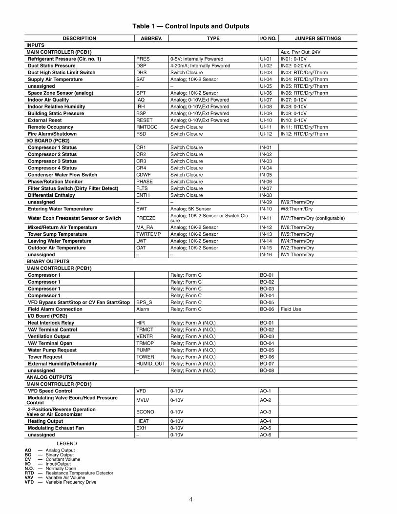
The controller is designed to provide heating and coolingcontrol, loop control, scheduling, and custom programming.The main processor provides 24 field points (12 universal in-puts, 6 relay outputs, and 6 analog outputs). Additional pointsare provided by the I/O (input/output) modules. Table 1 liststhe control inputs and outputs for all modules.
Specifications for the Multi-Protocol Controller may befound in the Open System literature.
WARNING
Electrical shock can cause personal injury and death.Shut off all power to this equipment during installationand service. There may be more than one disconnectswitch. Tag all disconnect locations to alert others not torestore power until work is completed.
CAUTION
This unit uses a microprocessor-based electronic controlsystem. Do not use jumpers or other tools to short outcomponents, or to bypass or otherwise depart from rec-ommended procedures. Any short-to-ground of the con-trol board or accompanying wiring may destroy theelectronic modules or electrical components.
OMNIZONE™50XJ050-104
Water-Cooled Indoor Self-Contained Systemswith Multi-Protocol Controller 6126
* Sponsored by ASHRAE (American Society of Heating, Refrigerat-ing and Air Conditioning Engineers).
† Registered trademark of Schneider Electric.** Registered trademark of Echelon Corporation. Requires additional
hardware card.
2
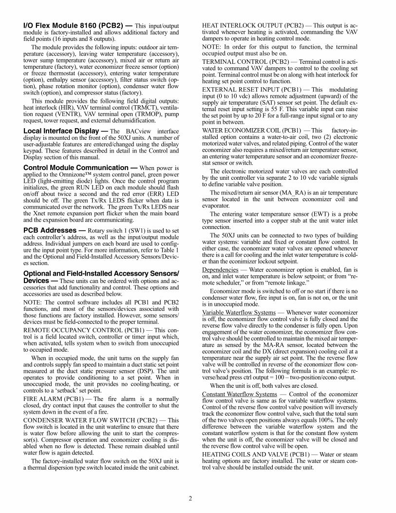
I/O Flex Module 8160 (PCB2) — This input/outputmodule is factory-installed and allows additional factory andfield points (16 inputs and 8 outputs).
The module provides the following inputs: outdoor air tem-perature (accessory), leaving water temperature (accessory),tower sump temperature (accessory), mixed air or return airtemperature (factory), water economizer freeze sensor (option)or freeze thermostat (accessory), entering water temperature(option), enthalpy sensor (accessory), filter status switch (op-tion), phase rotation monitor (option), condenser water flowswitch (option), and compressor status (factory).
This module provides the following field digital outputs:heat interlock (HIR), VAV terminal control (TRMCT), ventila-tion request (VENTR), VAV terminal open (TRMOP), pumprequest, tower request, and external dehumidification.
Local Interface Display — The BACview interfacedisplay is mounted on the front of the 50XJ units. A number ofuser-adjustable features are entered/changed using the displaykeypad. These features described in detail in the Control andDisplay section of this manual.
Control Module Communication — When power isapplied to the Omnizone™ system control panel, green powerLED (light-emitting diode) lights. Once the control programinitializes, the green RUN LED on each module should flashon/off about twice a second and the red error (ERR) LEDshould be off. The green Tx/Rx LEDS flicker when data iscommunicated over the network. The green Tx/Rx LEDS nearthe Xnet remote expansion port flicker when the main boardand the expansion board are communicating.
PCB Addresses — Rotary switch 1 (SW1) is used to seteach controller’s address, as well as the input/output moduleaddress. Individual jumpers on each board are used to config-ure the input point type. For more information, refer to Table 1and the Optional and Field-Installed Accessory Sensors/Devic-es section.
Optional and Field-Installed Accessory Sensors/Devices — These units can be ordered with options and ac-cessories that add functionality and control. These options andaccessories are used as described below.NOTE: The control software includes all PCB1 and PCB2functions, and most of the sensors/devices associated withthose functions are factory installed. However, some sensors/devices must be field-connected to the proper terminal.REMOTE OCCUPANCY CONTROL (PCB1) — This con-trol is a field located switch, controller or timer input which,when activated, tells system when to switch from unoccupiedto occupied mode.
When in occupied mode, the unit turns on the supply fanand controls supply fan speed to maintain a duct static set pointmeasured at the duct static pressure sensor (DSP). The unitoperates to provide conditioning to a set point. When inunoccupied mode, the unit provides no cooling/heating, orcontrols to a ‘setback’ set point. FIRE ALARM (PCB1) — The fire alarm is a normallyclosed, dry contact input that causes the controller to shut thesystem down in the event of a fire.CONDENSER WATER FLOW SWITCH (PCB2) — Thisflow switch is located in the unit waterline to ensure that thereis water flow before allowing the unit to start the compres-sor(s). Compressor operation and economizer cooling is dis-abled when no flow is detected. These remain disabled untilwater flow is again detected.
The factory-installed water flow switch on the 50XJ unit isa thermal dispersion type switch located inside the unit cabinet.
HEAT INTERLOCK OUTPUT (PCB2) — This output is ac-tivated whenever heating is activated, commanding the VAVdampers to operate in heating control mode.NOTE: In order for this output to function, the terminaloccupied output must also be on. TERMINAL CONTROL (PCB2) — Terminal control is acti-vated to command VAV dampers to control to the cooling setpoint. Terminal control must be on along with heat interlock forheating set point control to function.EXTERNAL RESET INPUT (PCB1) — This modulatinginput (0 to 10 vdc) allows remote adjustment (upward) of thesupply air temperature (SAT) sensor set point. The default ex-ternal reset input setting is 55 F. This variable input can raisethe set point by up to 20 F for a full-range input signal or to anypoint in between.WATER ECONOMIZER COIL (PCB1) — This factory-in-stalled option contains a water-to-air coil, two (2) electronicmotorized water valves, and related piping. Control of the watereconomizer also requires a mixed/return air temperature sensor,an entering water temperature sensor and an economizer freeze-stat sensor or switch.
The electronic motorized water valves are each controlledby the unit controller via separate 2 to 10 vdc variable signalsto define variable valve position.
The mixed/return air sensor (MA_RA) is an air temperaturesensor located in the unit between economizer coil andevaporator.
The entering water temperature sensor (EWT) is a probetype sensor inserted into a copper stub at the unit water inletconnection.
The 50XJ units can be connected to two types of buildingwater systems: variable and fixed or constant flow control. Ineither case, the economizer water valves are opened wheneverthere is a call for cooling and the inlet water temperature is cold-er than the econimizer lockout setpoint.Dependencies — Water economizer option is enabled, fan ison, and inlet water temperature is below setpoint; or from “re-mote scheduler,” or from “remote linkage.”
Economizer mode is switched to off or no start if there is nocondenser water flow, fire input is on, fan is not on, or the unitis in unoccupied mode.Variable Waterflow Systems — Whenever water economizeris off, the economizer flow control valve is fully closed and thereverse flow valve directly to the condenser is fully open. Uponengagement of the water economizer, the economizer flow con-trol valve should be controlled to maintain the mixed air temper-ature as sensed by the MA-RA sensor, located between theeconomizer coil and the DX (direct expansion) cooling coil at atemperature near the supply air set point. The the reverse flowvalve will be controlled in reverse of the economizer flow con-trol valve’s position. The following formula is an example: re-verse/head press ctrl output = 100 – two-position/econo output.
When the unit is off, both valves are closed.Constant Waterflow Systems — Control of the economizerflow control valve is same as for variable waterflow systems.Control of the reverse flow control valve position will inverselytrack the economizer flow control valve, such that the total sumof the two valves open positions always equals 100%. The onlydifference between the variable waterflow system and theconstant waterflow system is that for the constant flow systemwhen the unit is off, the economizer valve will be closed andthe reverse flow control valve will be open.HEATING COILS AND VALVE (PCB1) — Water or steamheating options are factory installed. The water or steam con-trol valve should be installed outside the unit.
3
HEATING - ELECTRIC HEAT (PCB1) — The controllerprovides a 0 to 10 vdc signal to control remote electric heat. Afield-installed step sequencer can be used to convert this signalin to 2, 4 or more heating stages.A single controller output is used to drive either a hydronicheating coil or the electric heat, so without field modifications,these are mutually exclusive options.HEAD PRESSURE CONTROL (PCB1) — Head pressurecontrol is required for unit installations that will experience en-tering condenser water temperatures of 55 F or lower.NOTE: Head pressure control is not needed or used inconjunction with a water economizer. A refrigerant pressuretransducer monitors head pressure on compressor circuit 1,allowing the unit main controller to regulate water flow ratein main water line entering the unit (flow to all condensers).(Water header design to the condensers will be optimizedsuch as to provide relative flow rates to each condenserbased on its compressor capacity, enabling successfulwaterflow control at the main entering pipe.) There are twopossible water valve configurations, as outlined below.
Pressure transducer input is factory installed in thedischarge line of compressor circuit 1. It is provided 5 vdc bythe unit main controller and returns a signal 1 to 5 vdc linearly.The sensor’s range is 0 to 550 psig.
Water Valve(s) Control
Variable Building Waterflow Systems — Variable waterflowconfigurations use only one water valve in the main watersupply pipe. The factory-installed valve is a normally openmotorized variable control type. The valve is controlled by a2 to 10 vdc signal from the main unit controller using thereverse/head pressure control output, which modulates tomaintain the head pressure set point.Constant Building Waterflow Systems — Constant waterflowconfigurations use two (2) water valves, only one of which is inthe main water supply pipe. The second valve is located in abypass pipe to the main outlet water pipe branched off of thesupply pipe immediately ahead of the first valve. This valve issame type, but normally closed and is controlled in unison withthe first valve, but opposite position, such that the total openingof the 2 valves always equals 100%.VFD BYPASS (PCB1) — The variable frequency drive(VFD) bypass option provides backup for the VFD in VAVunits. The bypass includes a control switch to select across-the-line operation or operation through the VFD. When the bypassis switched to across-the-line operation, the fan will not startuntil the user indicates that the VFD access doors are secure viathe BACview keypad. The controller provides an output to sig-nal the remote VAV dampers to open fully before the fan isstarted at full speed. A duct high static (DHS) switch shutsdown the fan if the duct static exceeds the switch setting.VENTILATION OUTPUT (PCB2) — The ventilation outputis a controller output signal (available for field connection) to afield-supplied ventilation damper(s). This signal is activatedwhenever the unit is in the occupied mode.SPACE TEMPERATURE SENSOR (PCB2) — A field-sup-plied Carrier space temperature sensor is required to maintainspace temperature in sensor mode.SUPPLY AIR RESET — Supply air temperature set pointmay be reset using one of several sensors. In the case of multi-ple sensors and configurations, the precedence of sensor use isfrom the top of the list to the bottom:• EWT (PCB2) — EWT sensor installed, entering water
temperature reset configuration on• SPT (PCB1) — Space reset configuration on• MA_RA (PCB2) — Configured for return air sensing
EXHAUST FAN CONTROL OUTPUT (PCB1) — This out-put is activated whenever the unit is in the occupied mode. Thisis a 0 to10 vdc output that controls based on the building pres-sure input set point.CONDENSER WATER PUMP REQUEST (PCB2) — Thisrelay output (provided for field connection) is used to start/stopthe remote condenser water pump. This output is engagedwhen the unit is in cooling mode and the supply fan is operat-ing. This output is also engaged if the economizer freeze pro-tection is activated.WATER TOWER REQUEST (PCB2) — This relay output(provided for field connection) is used to start/stop a remotewater cooling tower. This output is engaged when the unit is incooling mode and the supply fan is operating.PHASE LOSS/REVERSAL PROTECTION SWITCH(PCB2) — A phase loss/reversal switch may be installed todetect over/under voltage conditions and phase loss or reversal.This is a factory-installed option. This switch monitors the unitpower supply leads to detect phase loss or reversal. If theswitch detects improper phasing, an input is sent to the unitcontroller, which shuts the unit down. When the switch opens,the controller outputs are forced off, the alarm output willclose, the red alarm lamp will be lit on the BACview display,and a system alarm will be generated. Unit reset is automaticwhen the voltage and power phases have been restored.FREEZE THERMOSTAT (FREEZ) (PCB2) — The economiz-er freezestat, used in conjunction with an optional water econo-mizer coil or heating coil, is a factory-installed averaging airtemperature sensor positioned in the unit inlet airstream. Thismay be either a thermistor sensor (automatic reset) or a switchwith capillary tube (manual reset). The unit activates freezeprotection when the sensed air temperature falls below 37 F. Infreeze conditions, the supply fan will be stopped, all compres-sors will stop, the economizer valve will open to 100%, thepump request output will remain on, and the alarm lamp willlight. This will maintain condenser water flow through the coilto prevent freezing the coil while stopping all other operationsthat could have contributed or will be affected by the freezecondition. Unit reset is automatic when the contacts on thefreeze protection switch close again OR when the thermistorsensed air temperature exceeds 42 F.TOWER SUMP TEMPERATURE SENSOR (PCB2) —This field sensor is used for monitoring (only) the tower sumptemperature.LEAVING WATER TEMPERATURE SENSOR(PCB2) — This sensor is used only for monitoring the leavingwater temperature.BUILDING STATIC PRESSURE SENSOR (PCB1) —This sensor is used to control the speed of the building exhaustfan to maintain the building static pressure.BUILDING EXHAUST FAN SPEED CONTROL(PCB1) — This output controls building exhaust fan speed.INDOOR AIR QUALITY (CO2) SENSOR (PCB1) — Thissensor monitors CO2 levels and is used to provide demand ven-tilation override with an air economizer.OUTDOOR AIR TEMPERATURE SENSOR (PCB2) —This sensor is used to monitor outdoor air temperature. Whenan air economizer is installed, this is used for changeover andlockout.INDOOR RELATIVE HUMIDITY SENSOR (PCB1) —This sensor monitors the indoor relative humidity and controlsthe humidity control relay.HUMIDITY CONTROL RELAY (PCB2, DEHUMID-IFY) — This relay controls a humidifier or dehumidificationdevice.
4
Table 1 — Control Inputs and Outputs
LEGEND
DESCRIPTION ABBREV. TYPE I/O NO. JUMPER SETTINGSINPUTSMAIN CONTROLLER (PCB1) Aux. Pwr Out: 24V Refrigerant Pressure (Cir. no. 1) PRES 0-5V; Internally Powered UI-01 IN01: 0-10V Duct Static Pressure DSP 4-20mA; Internally Powered UI-02 IN02: 0-20mA Duct High Static Limit Switch DHS Switch Closure UI-03 IN03: RTD/Dry/Therm Supply Air Temperature SAT Analog; 10K-2 Sensor UI-04 IN04: RTD/Dry/Therm unassigned – – UI-05 IN05: RTD/Dry/Therm Space Zone Sensor (analog) SPT Analog; 10K-2 Sensor UI-06 IN06: RTD/Dry/Therm Indoor Air Quality IAQ Analog; 0-10V,Ext Powered UI-07 IN07: 0-10V Indoor Relative Humidity IRH Analog; 0-10V,Ext Powered UI-08 IN08: 0-10V Building Static Pressure BSP Analog; 0-10V,Ext Powered UI-09 IN09: 0-10V External Reset RESET Analog; 0-10V,Ext Powered UI-10 IN10: 0-10V Remote Occupancy RMTOCC Switch Closure UI-11 IN11: RTD/Dry/Therm Fire Alarm/Shutdown FSD Switch Closure UI-12 IN12: RTD/Dry/ThermI/O BOARD (PCB2) Compressor 1 Status CR1 Switch Closure IN-01 Compressor 2 Status CR2 Switch Closure IN-02 Compressor 3 Status CR3 Switch Closure IN-03 Compressor 4 Status CR4 Switch Closure IN-04 Condenser Water Flow Switch CDWF Switch Closure IN-05 Phase/Rotation Monitor PHASE Switch Closure IN-06 Filter Status Switch (Dirty Filter Detect) FLTS Switch Closure IN-07 Differential Enthalpy ENTH Switch Closure IN-08 unassigned – – IN-09 IW9:Therm/Dry Entering Water Temperature EWT Analog; 5K Sensor IN-10 W8:Therm/Dry
Water Econ Freezestat Sensor or Switch FREEZE Analog; 10K-2 Sensor or Switch Clo-sure IN-11 IW7:Therm/Dry (configurable)
Mixed/Return Air Temperature MA_RA Analog; 10K-2 Sensor IN-12 IW6:Therm/Dry Tower Sump Temperature TWRTEMP Analog; 10K-2 Sensor IN-13 IW5:Therm/Dry Leaving Water Temperature LWT Analog; 10K-2 Sensor IN-14 IW4:Therm/Dry Outdoor Air Temperature OAT Analog; 10K-2 Sensor IN-15 IW2:Therm/Dry unassigned – – IN-16 IW1:Therm/DryBINARY OUTPUTSMAIN CONTROLLER (PCB1) Compressor 1 Relay; Form C BO-01 Compressor 1 Relay; Form C BO-02 Compressor 1 Relay; Form C BO-03 Compressor 1 Relay; Form C BO-04 VFD Bypass Start/Stop or CV Fan Start/Stop BPS_S Relay; Form C BO-05 Field Alarm Connection Alarm Relay; Form C BO-06 Field Use I/O Board (PCB2) Heat Interlock Relay HIR Relay; Form A (N.O.) BO-01 VAV Terminal Control TRMCT Relay; Form A (N.O.) BO-02 Ventilation Output VENTR Relay; Form A (N.O.) BO-03 VAV Terminal Open TRMOP Relay; Form A (N.O.) BO-04 Water Pump Request PUMP Relay; Form A (N.O.) BO-05 Tower Request TOWER Relay; Form A (N.O.) BO-06 External Humidify/Dehumidify HUMID_OUT Relay; Form A (N.O.) BO-07 unassigned – Relay; Form A (N.O.) BO-08ANALOG OUTPUTSMAIN CONTROLLER (PCB1) VFD Speed Control VFD 0-10V AO-1 Modulating Valve Econ./Head Pressure Control MVLV 0-10V AO-2
2-Position/Reverse OperationValve or Air Economizer ECONO 0-10V AO-3
Heating Output HEAT 0-10V AO-4 Modulating Exhaust Fan EXH 0-10V AO-5 unassigned – 0-10V AO-6
AO — Analog OutputBO — Binary OutputCV — Constant VolumeI/O — Input/OutputN.O. — Normally OpenRTD — Resistance Temperature DetectorVAV — Variable Air VolumeVFD — Variable Frequency Drive
5
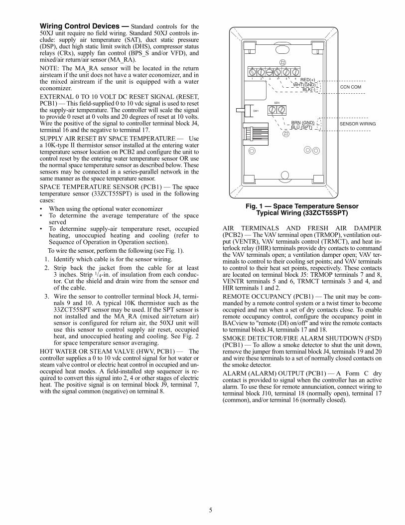
Wiring Control Devices — Standard controls for the50XJ unit require no field wiring. Standard 50XJ controls in-clude: supply air temperature (SAT), duct static pressure(DSP), duct high static limit switch (DHS), compressor statusrelays (CRx), supply fan control (BPS_S and/or VFD), andmixed/air return/air sensor (MA_RA). NOTE: The MA_RA sensor will be located in the returnairsteam if the unit does not have a water economizer, and inthe mixed airstream if the unit is equipped with a watereconomizer.EXTERNAL 0 TO 10 VOLT DC RESET SIGNAL (RESET,PCB1) — This field-supplied 0 to 10 vdc signal is used to resetthe supply-air temperature. The controller will scale the signalto provide 0 reset at 0 volts and 20 degrees of reset at 10 volts.Wire the positive of the signal to controller terminal block J4,terminal 16 and the negative to terminal 17.SUPPLY AIR RESET BY SPACE TEMPERATURE — Usea 10K-type II thermistor sensor installed at the entering watertemperature sensor location on PCB2 and configure the unit tocontrol reset by the entering water temperature sensor OR usethe normal space temperature sensor as described below. Thesesensors may be connected in a series-parallel network in thesame manner as the space temperature sensor.SPACE TEMPERATURE SENSOR (PCB1) — The spacetemperature sensor (33ZCT55SPT) is used in the followingcases:• When using the optional water economizer• To determine the average temperature of the space
served• To determine supply-air temperature reset, occupied
heating, unoccupied heating and cooling (refer toSequence of Operation in Operation section).To wire the sensor, perform the following (see Fig. 1).
1. Identify which cable is for the sensor wiring.2. Strip back the jacket from the cable for at least
3 inches. Strip 1/4-in. of insulation from each conduc-tor. Cut the shield and drain wire from the sensor endof the cable.
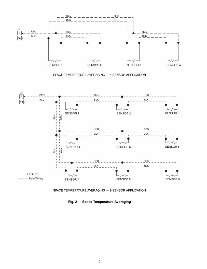
3. Wire the sensor to controller terminal block J4, termi-nals 9 and 10. A typical 10K thermistor such as the33ZCT55SPT sensor may be used. If the SPT sensor isnot installed and the MA_RA (mixed air/return air)sensor is configured for return air, the 50XJ unit willuse this sensor to control supply air reset, occupiedheat, and unoccupied heating and cooling. See Fig. 2for space temperature sensor averaging.
HOT WATER OR STEAM VALVE (HWV, PCB1) — Thecontroller supplies a 0 to 10 vdc control signal for hot water orsteam valve control or electric heat control in occupied and un-occupied heat modes. A field-installed step sequencer is re-quired to convert this signal into 2, 4 or other stages of electricheat. The positive signal is on terminal block J9, terminal 7,with the signal common (negative) on terminal 8.
AIR TERMINALS AND FRESH AIR DAMPER(PCB2) — The VAV terminal open (TRMOP), ventilation out-put (VENTR), VAV terminals control (TRMCT), and heat in-terlock relay (HIR) terminals provide dry contacts to commandthe VAV terminals open; a ventilation damper open; VAV ter-minals to control to their cooling set points; and VAV terminalsto control to their heat set points, respectively. These contactsare located on terminal block J5: TRMOP terminals 7 and 8,VENTR terminals 5 and 6, TRMCT terminals 3 and 4, andHIR terminals 1 and 2.REMOTE OCCUPANCY (PCB1) — The unit may be com-manded by a remote control system or a twist timer to becomeoccupied and run when a set of dry contacts close. To enableremote occupancy control, configure the occupancy point inBACview to "remote (DI) on/off" and wire the remote contactsto terminal block J4, terminals 17 and 18.SMOKE DETECTOR/FIRE ALARM SHUTDOWN (FSD)(PCB1) — To allow a smoke detector to shut the unit down,remove the jumper from terminal block J4, terminals 19 and 20and wire these terminals to a set of normally closed contacts onthe smoke detector.ALARM (ALARM) OUTPUT (PCB1) — A Form C drycontact is provided to signal when the controller has an activealarm. To use these for remote annunciation, connect wiring toterminal block J10, terminal 18 (normally open), terminal 17(common), and/or terminal 16 (normally closed).
2 3 4 5 61
SW1
SEN
BRN (GND)BLU (SPT)
RED(+)WHT(GND)
BLK(-) CCN COM
SENSOR WIRING
Fig. 1 — Space Temperature SensorTypical Wiring (33ZCT55SPT)
a33-675ef
6
J4
9
10
RED
BLK
RED RED
BLK BLK
BLK
RED
BLK
RED
SENSOR 1 SENSOR 2 SENSOR 3 SENSOR 4
J4
9
10
RED
BLK
RED
BLK
SENSOR 2SENSOR 1
RED
RED
BLK
SENSOR 3
SENSOR 4
BLK
BLK
RE
D
RED RED
BLK BLK
SENSOR 8 SENSOR 9
SENSOR 5
RED
BLK
SENSOR 6
SENSOR 7
BLK
RE
D
SPACE TEMPERATURE AVERAGING — 4 SENSOR APPLICATION
SPACE TEMPERATURE AVERAGING — 9 SENSOR APPLICATION
Fig. 2 — Space Temperature Averaging
LEGEND
Field Wiring
a50-8742
a50-8743
7
CONTROL AND DISPLAY
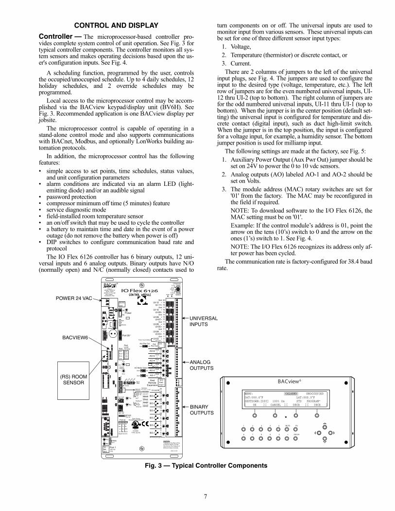
Controller — The microprocessor-based controller pro-vides complete system control of unit operation. See Fig. 3 fortypical controller components. The controller monitors all sys-tem sensors and makes operating decisions based upon the us-er's configuration inputs. See Fig. 4.
A scheduling function, programmed by the user, controlsthe occupied/unoccupied schedule. Up to 4 daily schedules, 12holiday schedules, and 2 override schedules may beprogrammed.
Local access to the microprocessor control may be accom-plished via the BACview keypad/display unit (BV6H). SeeFig. 3. Recommended application is one BACview display perjobsite.
The microprocessor control is capable of operating in astand-alone control mode and also supports communicationswith BACnet, Modbus, and optionally LonWorks building au-tomation protocols.
In addition, the microprocessor control has the followingfeatures:• simple access to set points, time schedules, status values,
and unit configuration parameters• alarm conditions are indicated via an alarm LED (light-
emitting diode) and/or an audible signal• password protection• compressor minimum off time (5 minutes) feature• service diagnostic mode• field-installed room temperature sensor• an on/off switch that may be used to cycle the controller• a battery to maintain time and date in the event of a power
outage (do not remove the battery when power is off)• DIP switches to configure communication baud rate and
protocolThe IO Flex 6126 controller has 6 binary outputs, 12 uni-
versal inputs and 6 analog outputs. Binary outputs have N/O(normally open) and N/C (normally closed) contacts used to
turn components on or off. The universal inputs are used tomonitor input from various sensors. These universal inputs canbe set for one of three different sensor input types:
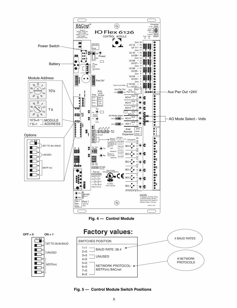
1. Voltage,2. Temperature (thermistor) or discrete contact, or3. Current. There are 2 columns of jumpers to the left of the universal
input plugs, see Fig. 4. The jumpers are used to configure theinput to the desired type (voltage, temperature, etc.). The leftrow of jumpers are for the even numbered universal inputs, UI-12 thru UI-2 (top to bottom). The right column of jumpers arefor the odd numbered universal inputs, UI-11 thru UI-1 (top tobottom). When the jumper is in the center position (default set-ting) the universal input is configured for temperature and dis-crete contact (digital input), such as duct high-limit switch.When the jumper is in the top position, the input is configuredfor a voltage input, for example, a humidity sensor. The bottomjumper position is used for milliamp input.
The following settings are made at the factory, see Fig. 5:1. Auxiliary Power Output (Aux Pwr Out) jumper should be
set on 24V to power the 0 to 10 vdc sensors.2. Analog outputs (AO) labeled AO-1 and AO-2 should be
set on Volts.3. The module address (MAC) rotary switches are set for
'01' from the factory. The MAC may be reconfigured inthe field if required. NOTE: To download software to the I/O Flex 6126, theMAC setting must be on '01'. Example: If the control module’s address is 01, point thearrow on the tens (10’s) switch to 0 and the arrow on theones (1’s) switch to 1. See Fig. 4.NOTE: The I/O Flex 6126 recognizes its address only af-ter power has been cycled.
The communication rate is factory-configured for 38.4 baudrate.
Aux +
GndAux Pwr Out+5V+24V
21
+43
56789
1011121314151617181920
UI-01+
Gnd+
Gnd+
+
Gnd+
+
Gnd+
+
Gnd+
+
Gnd+
UI-02
UI-03UI-04
UI-05UI-06
UI-07UI-08
UI-09UI-10
UI-11UI-12
AO-2
AO-3
AO-4
AO-1Gnd
+
+
3
12
7+Gnd
Gnd+
6
45
Gnd 89+
GndAO-5 10
GndAO-6 1211+
GndXnet -Xnet +
XnetRemote
Expansion
2BO-11
9BO-3
BO-245
3
BO-4
678
BO-5
BO-6
121110
1314
1615
1817
I/O Flex 6126
Pwr Out
AO Mode Select10V20mA
20mA 10V
BACnet® Universal
Mode
RTD
0-10V
0-20mA
PowerOff
24VAC
Gnd
Batt
CR2032
- +
Port 2b*
Gnd
Rnet +
Rnet -
+12V
Rnet
+12V
Rnet
Rnet-
GndRnet+
Sense
LocalAccess
Run
Error
Rx
Tx
Module10's
9600
76.8k
19.2k
38.4k
Baud
Full HalfDuplex
BT485
BT485
Net + Port 1
GndNet -
Tx
RxCAUTION:To Reduce The Risk of Fire
Interconnect the Outputs ofDifferent Class 2 Circuits.
or Electric Shock, Do Not
BO Rating 5A @ 250VAC
Class 224VAC, 50-60 Hz
20VA, 0.83A
Use CopperConductors Only
232EIA- EIA-485
Port 1
Port 2a
ThermDry
Unused5678
NetworkSwitches(0 = off, 1 = on)
MSTP (m)MSTP (s)PTP
SLTA*PlugIn*Ethernet
8 7 6 5Protocol
0 0 0 00 0 0 10 0 1 0
0 0 1 1
0 1 0 01 1 0 11 1 1 01 1 1 1
BA
Cne
t
N2
Modbus
LON
®
®
®
®
Port 2a2w 4w
Tx+
n/c
n/c
Net+
Rx+
Rx-
Tx-Net-
232Tx
DTR
DCD
Rx
Signal Ground
Address1's
On
Pulse Count Ability
Input
Select
Rate
Format
Made in USAARC156 Only
26VDC, 0.17A, 4W
Management Equipment
TYPE: 002108
Open Energy
R
88FOE143900
1920
Unused
Even Odd
POWER 24 VAC
BACVIEW6
(RS) ROOMSENSOR
UNIVERSALINPUTS
ANALOGOUTPUTS
BINARYOUTPUTS
MENU: <ALARM> UNOCCUPIEDOAT:000.0 ° .000:TAL F 0 °FSHUTDOWN:[Off] 100% OA STD PROGRAM”[ OK ][ CANCEL ][ DECR ][ INCR ]
1 2 3 4 5 MUTE FN
6 7 8 9 0 • ENTER
BACview6
Fig. 3 — Typical Controller Components
a62-608
8
Aux +
GndAux Pwr Out+5V+24V
21
+43
56789
1011121314151617181920
UI-01+
Gnd+
Gnd+
+
Gnd+
+
Gnd+
+
Gnd+
+
Gnd+
UI-02
UI-03UI-04
UI-05UI-06
UI-07UI-08
UI-09UI-10
UI-11UI-12
AO-2
AO-3
AO-4
AO-1Gnd
+
+
3
12
7+Gnd
Gnd+
6
45
Gnd 89+
GndAO-5 10
GndAO-6 1211+
GndXnet -Xnet +
XnetRemote
Expansion
2BO-11
9BO-3
BO-245
3
BO-4
678
BO-5
BO-6
121110
1314
1615
1817
I/O Flex 6126
Pwr Out
AO Mode Select10V20mA
20mA 10V
BACnet® Universal
Mode
RTD
0-10V
0-20mA
PowerOff
24VAC
Gnd
Batt
CR2032
- +
Port 2b*
Gnd
Rnet +
Rnet -
+12V
Rnet
+12V
Rnet
Rnet-
GndRnet+
Sense
LocalAccess
Run
Error
Rx
Tx
Module10's
9600
76.8k
19.2k
38.4k
Baud
Full HalfDuplex
BT485
BT485
Net + Port 1
GndNet -
Tx
RxCAUTION:To Reduce The Risk of Fire
Interconnect the Outputs ofDifferent Class 2 Circuits.
or Electric Shock, Do Not
BO Rating 5A @ 250VAC
Class 224VAC, 50-60 Hz
20VA, 0.83A
Use CopperConductors Only
232EIA- EIA-485
Port 1
Port 2a
ThermDry
Unused5678
NetworkSwitches(0 = off, 1 = on)
MSTP (m)MSTP (s)PTP
SLTA*PlugIn*Ethernet
8 7 6 5Protocol
0 0 0 00 0 0 10 0 1 0
0 0 1 1
0 1 0 01 1 0 11 1 1 01 1 1 1
BA
Cne
t
N2
Modbus
LON
®
®
®
®
Port 2a2w 4w
Tx+
n/c
n/c
Net+
Rx+
Rx-
Tx-Net-
232Tx
DTR
DCD
Rx
Signal Ground
Address1's
On
Pulse Count Ability
Input
Select
Rate
Format
Made in USAARC156 Only
26VDC, 0.17A, 4W
Management Equipment
TYPE: 002108
Open Energy
R
88FOE143900
1920
Unused
Even Odd
Aux Pwr Out +24V
AO Mode Select - Volts
Power Switch
Battery
10's
1's
1
3
452
78
9
6
0
1
3
45
2
78
9
6
0
ON 1
2 3
4 5
6 7
8
SET TO 38.4 BAUD
UNUSED
MSTP (m)
Module Address
Options
10’S=01’S=1
MODULEADDRESS
a62-606
Fig. 4 — Control Module
Factory values:SWITCHES POSITION
1=12=03=04=05=06=07=08=0
BAUD RATE: 38.4
UNUSED
NETWORK PROTOCOL:MSTP(m) BACnet
OFF = 0 ON = 1
SET TO 38.4k BAUD
UNUSED
MSTP(m)
ON 1
2 3
4 5
6 7
8
4 BAUD RATES
8 NETWORK PROTOCOLS
a62-576
Fig. 5 — Control Module Switch Positions
9
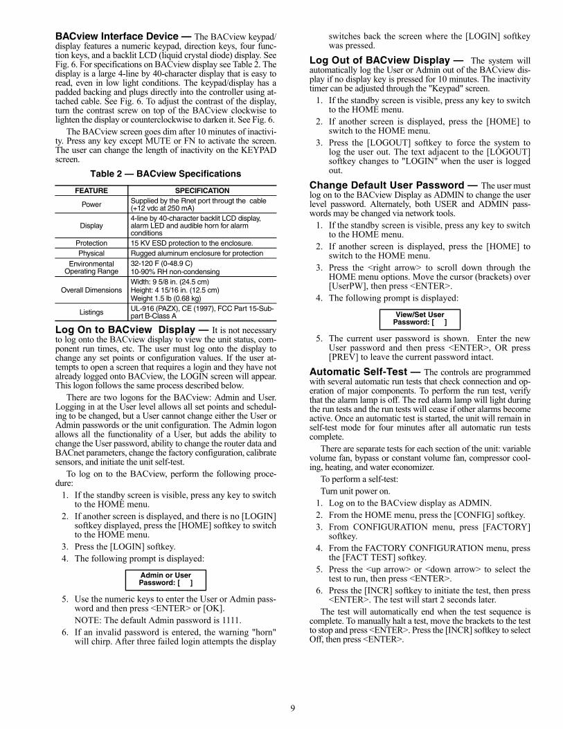
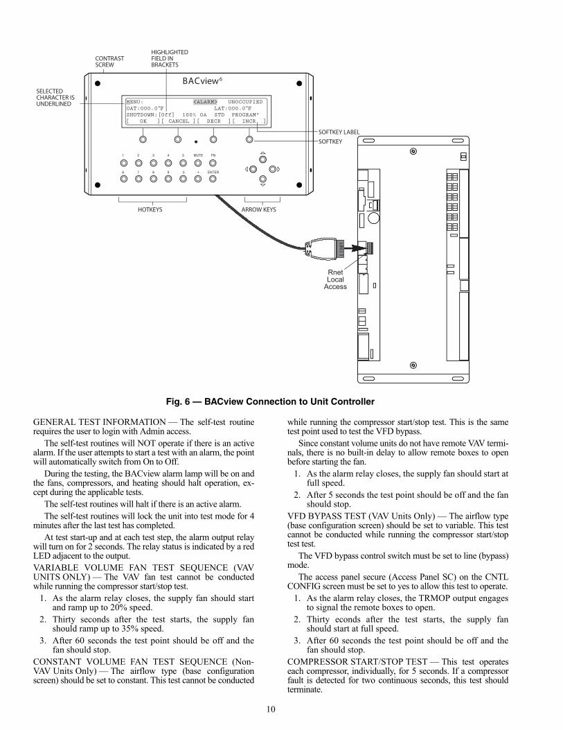
BACview Interface Device — The BACview keypad/display features a numeric keypad, direction keys, four func-tion keys, and a backlit LCD (liquid crystal diode) display. SeeFig. 6. For specifications on BACview display see Table 2. Thedisplay is a large 4-line by 40-character display that is easy toread, even in low light conditions. The keypad/display has apadded backing and plugs directly into the controller using at-tached cable. See Fig. 6. To adjust the contrast of the display,turn the contrast screw on top of the BACview clockwise tolighten the display or counterclockwise to darken it. See Fig. 6.
The BACview screen goes dim after 10 minutes of inactivi-ty. Press any key except MUTE or FN to activate the screen.The user can change the length of inactivity on the KEYPADscreen.
Table 2 — BACview Specifications
Log On to BACview Display — It is not necessaryto log onto the BACview display to view the unit status, com-ponent run times, etc. The user must log onto the display tochange any set points or configuration values. If the user at-tempts to open a screen that requires a login and they have notalready logged onto BACview, the LOGIN screen will appear.This logon follows the same process described below.
There are two logons for the BACview: Admin and User.Logging in at the User level allows all set points and schedul-ing to be changed, but a User cannot change either the User orAdmin passwords or the unit configuration. The Admin logonallows all the functionality of a User, but adds the ability tochange the User password, ability to change the router data andBACnet parameters, change the factory configuration, calibratesensors, and initiate the unit self-test.
To log on to the BACview, perform the following proce-dure:
1. If the standby screen is visible, press any key to switchto the HOME menu.
2. If another screen is displayed, and there is no [LOGIN]softkey displayed, press the [HOME] softkey to switchto the HOME menu.
3. Press the [LOGIN] softkey.4. The following prompt is displayed:
5. Use the numeric keys to enter the User or Admin pass-word and then press <ENTER> or [OK].NOTE: The default Admin password is 1111.
6. If an invalid password is entered, the warning "horn"will chirp. After three failed login attempts the display
switches back the screen where the [LOGIN] softkeywas pressed.
Log Out of BACview Display — The system willautomatically log the User or Admin out of the BACview dis-play if no display key is pressed for 10 minutes. The inactivitytimer can be adjusted through the "Keypad" screen.
1. If the standby screen is visible, press any key to switchto the HOME menu.
2. If another screen is displayed, press the [HOME] toswitch to the HOME menu.
3. Press the [LOGOUT] softkey to force the system tolog the user out. The text adjacent to the [LOGOUT]softkey changes to "LOGIN" when the user is loggedout.
Change Default User Password — The user mustlog on to the BACview Display as ADMIN to change the userlevel password. Alternately, both USER and ADMIN pass-words may be changed via network tools.
1. If the standby screen is visible, press any key to switchto the HOME menu.
2. If another screen is displayed, press the [HOME] toswitch to the HOME menu.
3. Press the <right arrow> to scroll down through theHOME menu options. Move the cursor (brackets) over[UserPW], then press <ENTER>.
4. The following prompt is displayed:
5. The current user password is shown. Enter the newUser password and then press <ENTER>, OR press[PREV] to leave the current password intact.
Automatic Self-Test — The controls are programmedwith several automatic run tests that check connection and op-eration of major components. To perform the run test, verifythat the alarm lamp is off. The red alarm lamp will light duringthe run tests and the run tests will cease if other alarms becomeactive. Once an automatic test is started, the unit will remain inself-test mode for four minutes after all automatic run testscomplete.
There are separate tests for each section of the unit: variablevolume fan, bypass or constant volume fan, compressor cool-ing, heating, and water economizer.
To perform a self-test:Turn unit power on.
1. Log on to the BACview display as ADMIN.2. From the HOME menu, press the [CONFIG] softkey.3. From CONFIGURATION menu, press [FACTORY]
softkey.4. From the FACTORY CONFIGURATION menu, press
the [FACT TEST] softkey.5. Press the <up arrow> or <down arrow> to select the
test to run, then press <ENTER>.6. Press the [INCR] softkey to initiate the test, then press
<ENTER>. The test will start 2 seconds later.The test will automatically end when the test sequence is
complete. To manually halt a test, move the brackets to the testto stop and press <ENTER>. Press the [INCR] softkey to selectOff, then press <ENTER>.
FEATURE SPECIFICATION
Power Supplied by the Rnet port througt the cable (+12 vdc at 250 mA)
Display4-line by 40-character backlit LCD display, alarm LED and audible horn for alarm conditions
Protection 15 KV ESD protection to the enclosure.Physical Rugged aluminum enclosure for protection
Environmental Operating Range
32-120 F (0-48.9 C)10-90% RH non-condensing
Overall DimensionsWidth: 9 5/8 in. (24.5 cm)Height: 4 15/16 in. (12.5 cm)Weight 1.5 lb (0.68 kg)
Listings UL-916 (PAZX), CE (1997), FCC Part 15-Sub-part B-Class A
Admin or UserPassword: [ ]
View/Set UserPassword: [ ]
10
GENERAL TEST INFORMATION — The self-test routinerequires the user to login with Admin access.
The self-test routines will NOT operate if there is an activealarm. If the user attempts to start a test with an alarm, the pointwill automatically switch from On to Off.
During the testing, the BACview alarm lamp will be on andthe fans, compressors, and heating should halt operation, ex-cept during the applicable tests.
The self-test routines will halt if there is an active alarm.The self-test routines will lock the unit into test mode for 4
minutes after the last test has completed.At test start-up and at each test step, the alarm output relay
will turn on for 2 seconds. The relay status is indicated by a redLED adjacent to the output.VARIABLE VOLUME FAN TEST SEQUENCE (VAVUNITS ONLY) — The VAV fan test cannot be conductedwhile running the compressor start/stop test.
1. As the alarm relay closes, the supply fan should startand ramp up to 20% speed.
2. Thirty seconds after the test starts, the supply fanshould ramp up to 35% speed.
3. After 60 seconds the test point should be off and thefan should stop.
CONSTANT VOLUME FAN TEST SEQUENCE (Non-VAV Units Only) — The airflow type (base configurationscreen) should be set to constant. This test cannot be conducted
while running the compressor start/stop test. This is the sametest point used to test the VFD bypass.
Since constant volume units do not have remote VAV termi-nals, there is no built-in delay to allow remote boxes to openbefore starting the fan.
1. As the alarm relay closes, the supply fan should start atfull speed.
2. After 5 seconds the test point should be off and the fanshould stop.
VFD BYPASS TEST (VAV Units Only) — The airflow type(base configuration screen) should be set to variable. This testcannot be conducted while running the compressor start/stoptest test.
The VFD bypass control switch must be set to line (bypass)mode.
The access panel secure (Access Panel SC) on the CNTLCONFIG screen must be set to yes to allow this test to operate.
1. As the alarm relay closes, the TRMOP output engagesto signal the remote boxes to open.
2. Thirty econds after the test starts, the supply fanshould start at full speed.
3. After 60 seconds the test point should be off and thefan should stop.
COMPRESSOR START/STOP TEST — This test operateseach compressor, individually, for 5 seconds. If a compressorfault is detected for two continuous seconds, this test shouldterminate.
RnetLocal
Access
MENU: <ALARM> UNOCCUPIEDOAT:000.0 °F LAT:000.0 °FSHUTDOWN:[Off] 100% OA STD PROGRAM”[ OK ][ CANCEL ][ DECR ][ INCR ]
BACview6
CONTRASTSCREW
HOTKEYS ARROW KEYS
SELECTEDCHARACTER ISUNDERLINED
SOFTKEY LABELSOFTKEY
HIGHLIGHTEDFIELD INBRACKETS
1 2 3 4 5 MUTE FN
6 7 8 9 0 • ENTER
Fig. 6 — BACview Connection to Unit Controller
a62-573
11
This test will operate the number of compressors indicatedon the "# of Comps" section of the BASE CONFIG screen.
1. As the alarm relay closes, Compressor 1 starts andoperates for 5 seconds.
2. One second after compressor 1 stops, compressor 2starts and operates for 5 seconds.
3. One second after compressor 2 stops, compressor 3 (ifconfigured) starts and operates for 5 seconds.
4. One second after compressor 3 stops, compressor 4 (ifconfigured) starts and operates for 5 seconds.
5. After the last configured compressor stops, the testpoint returns to off.
HEATING — This test operates the analog output used to con-trol a field-installed heating valve. The timing is set to allowthe use of a DC voltmeter to check the controller output.
This test will NOT test electric heat. If the heat type indicat-ed on the "Heat Config" section of the BASE CONFIG screenis set to "electric" this test will not run.
1. As the alarm relay closes, the heating output will be0 vdc.
2. Ten seconds later the heating output moves to 5 vdc.3. Ten seconds later the heating output moves to 10 vdc.4. Ten seconds later the test point returns to Off and the
heat output returns to normal control.WATER ECONOMIZER (H2O ECON) — This test checksoperation of the modulating valve (MVLV) and economizervalve (ECONO).
1. As the alarm relay closes, the output to both valves is0 vdc. Both valves should close.
2. Two minutes later, economizer valve opens (10 vdc)and modulating valve remains closed (0 vdc).
3. Two minutes later, economizer valve closes (0 vdc)and modulating valve opens (10 vdc)
4. Two minutes later the test point returns to off and thevalves return to normal control.
Set the Clock — The user must be logged on as either aUser or Admin to set the clock. To set the clock, perform thefollowing procedure:
1. From the HOME menu, press the arrow keys until thecursor brackets are around ClockSet, then press<ENTER>.
2. Use the arrow keys to scroll around the screen andselect the data fields to change.
3. To change a field, move the cursor (brackets) to thedesired field then press enter.
4. If the wrong field is entered or you do not want tochange a value, press [CANCEL] to leave the currentsetting intact.
5. To setup Daylight Savings time and Standard time,move the cursor (brackets) over DST and then press<ENTER>. You can then scroll through and set thetime of day to start daylight savings mode (default is02:00), the amount of time to offset (default is 60 min-utes), beginning (B) and ending (D) dates.
Configure Schedules — Local schedules are onemethod of starting and stopping the unit at specified intervals.There are four normal schedules that provide day to day opera-tion. There are twelve holiday schedules that are used to over-ride the normal schedule and set the unit to unoccupied mode.There are two override schedules that are used to override thenormal and holiday schedules to force the unit into occupiedmode.
The user must be logged on as User or Admin to configurethe schedules using following procedure.NORMAL (LOCAL) SCHEDULES
1. From the HOME menu, select the the [CONFIG] soft-key to enter the CONFIGURATION menu.
2. Use the arrow keys to select OCCUPANCY, then press<ENTER>.
3. Press the [LOCAL] softkey to adjust the normal sched-ules.
4. Use arrow keys to scroll around the screen and selectthe data field to change. These buttons scroll throughthe data fields, as well as up and down the screen.
5. To change a field, move the cursor brackets to thedesired field then press <ENTER>.
6. If the wrong field is entered or you do not want tochange a value, press [CANCEL] to leave the currentsetting intact.
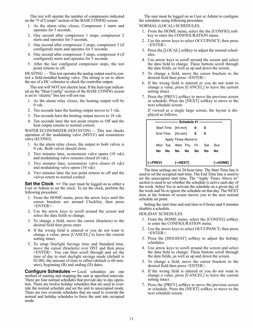
7. Press the [PREV] softkey to move the previous screenor schedule. Press the [NEXT] softkey to move to thenext schedule screen.If viewed as a single large screen, the layout is dis-played as follows:
The time settings are in 24-hour time. The Start Time line isused to set the occupied start time. The End Time line is used toset the unoccupied start time. The “Apply Times Above to”section is used to set whether the schedule is active each day ofthe week. Select Yes to activate the schedule on a given day ofthe week and No to ignore the schedule on that day. The NEXTitem at the bottom of screen moves you to the next normalschedule set point.
Setting the start time and end time to 0 hours and 0 minutesdisables a schedule.HOLIDAY SCHEDULES
1. From the HOME menu, select the [CONFIG] softkeyto enter the CONFIGURATION menu.
2. Use the arrow keys to select OCCUPANCY, then press<ENTER>.
3. Press the [HOLIDAY] softkey to adjust the holidayschedules.
4. Use arrow keys to scroll around the screen and selectthe data field to change. These buttons scroll throughthe data fields, as well as up and down the screen.
5. To change a field, move the cursor brackets to thedesired field then press <ENTER>.
6. If the wrong field is entered or you do not want tochange a value, press [CANCEL] to leave the currentsetting intact.
7. Press the [PREV] softkey to move the previous screenor schedule. Press the [NEXT] softkey to move to thenext schedule screen.
--------------------- Schedule #1 ---------------------
Start Time [hh:mm] 0: 0
End Time [hh:mm] 0: 0
Apply Times Above to
Mon Tue Wed Thu Fri Sat Sun
No No No No No No No
[->PREV] [->NEXT] [->HOME]
12
If viewed as a single large screen, the layout is as follows:
The Month and Day entries select the month (1 to 12) andday (1 to 31) of the holiday. The time settings are in 24-hourtime, with Start Time used to set the time of day to start of theholiday. The End Time line is used to set the end of the holiday.The NEXT item at the bottom of screen moves you to the nextholiday schedule setpoint.
Setting the month or day or start time and end time to 0 dis-ables the holiday schedule.
The holiday schedule cancels any normal schedule set forthe holiday date and time. If a normal schedule is set from 0700to 1800 hours and a holiday schedule is set for the same dayfrom 0800 to 1700, the unit will be unoccupied from midnightto 0700. The unit will change to occupied mode at 0700 until0800. At 0800 the holiday schedule forces the unit tounoccupied mode until 1700. At 1700, control returns to thenormal schedule and the unit goes occupied from 1700 to1800. At 1800, the unit returns to unoccupied mode per thenormal schedule.OVERRIDE SCHEDULES
1. From the HOME menu, select the [CONFIG] softkeyto enter the CONFIGURATION menu.
2. Use the arrow keys to select OCCUPANCY, then press<ENTER>.
3. Press the [OVERRIDE] softkey to adjust the overrideschedules.
4. Use arrow keys to scroll around the screen and selectthe data field to change. These buttons scroll throughthe data fields, as well as up and down the screen.
5. To change a field, move the cursor brackets to thedesired field then press <ENTER>.
6. If the wrong field is entered or you do not want tochange a value, press [CANCEL] to leave the currentsetting intact.
7. Press the [PREV] softkey to move the previous screenor schedule. Press the [NEXT] softkey to move to thenext schedule screen.
If viewed as a single large screen, the layout is as follows:
The Month and Day entries select the month (1 to 12) andday (1 to 31) of the override. The time settings are in 24-hourtime, with Start Time used to set the time of day to start of the
override. The End Time line is used to set the end of the over-ride. The NEXT item at the bottom of screen moves you to thenext override schedule set point.
Setting the month or day or start time and end time to 0 dis-ables the override schedule.
The override schedule has the highest priority of any sched-ule. When an override schedule is active, it overrides any nor-mal or holiday schedule and forces the unit to occupied mode.In the example listed under the holiday schedule, assume anoverride schedule is set for 1300 to 1400 of that day. The unitoperation remains the same, except the unit will switch to oc-cupied mode from 1300 to 1400.
Adjust Set Points — The user must be logged on asUser or Admin to configure set points.
1. From the HOME menu, select the [CONFIG] softkeyto enter the CONFIGURATION menu.
2. Use the arrow keys to select SETPOINT, then press<ENTER>.
3. Use arrow keys to scroll around the screen and selectthe data field to change. These buttons scroll throughthe data fields, as well as up and down the screen.
4. To change a field, move the cursor brackets to thedesired field then press <ENTER>.
5. If the wrong field is entered or you do not want tochange a value, press [CANCEL] to leave the currentsetting intact.
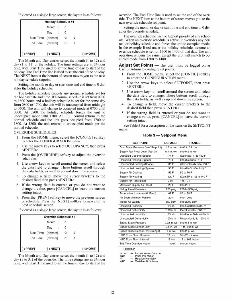
See Table 3 for a description of the items on the SETPOINTmenu.
Table 3 — Setpoint Menu
LEGEND
--------------------- Holiday Schedule #1 ---------------------
Month : 0
Day : 0
Start Time [hh:mm] 0: 0
End Time [hh:mm] 0: 0
[->PREV] [->NEXT] [->HOME]
--------------------- Override Schedule #1 ---------------------
Month : 0
Day : 0
Start Time [hh:mm] 0: 0
End Time [hh:mm] 0: 0
[->PREV] [->NEXT] [->HOME]
SET POINT DEFAULT RANGEDuct Static Pressure (VAV Setpoint) 1.5 in. wc 0.05 to 3 in. wc
Supply Fan Proof Level (Fan On) 0.4 in. wc 0 to 0.5 in. wc
Occupied Cooling (Space) 74 F (OccHeat+1) to 100 F
Occupied Heating (Space) 70 F 0 to (OccCool -1) F
Unoccupied Cooling (Space) 85 F (UnOccHeat+1) to 100 F
Unoccupied Heating (Space) 55 F 0 to (UnOccCool -1) F
Supply Air Cooling 55 F 50 to 70 F
Supply Air Heating 120 F (CoolSP + 10) to 140 F
Supply Air Reset Ratio 3.0 F 1 to 10 F
Maximum Supply Air Reset 20 F 0 to 20 F
Refrig. Head Pressure 225 psig 200 to 300 psig
Economizer Lockout (Air Econ) 68 F 50 to 85 F
Air Econ Minimum Position 20% 0 to 100%
Indoor Air Quality 850 ppm 0 to 2000 ppm
Occupied Humidify 0% rh 0 to OccDehumid% rh
Occupied Dehumidify 100% rh OccHumid to 100% rh
Unoccupied Humidify 0% rh 0 to UnoccDehumid% rh
Unoccupied Dehumidify 100% rh UnoccHumid to 100% rh
Space Static Pressure 0.02 in. wc 0 to 0.3 in. wc
Space Static Sensor-Low -0.5 in. wc -1 to -0.2 in. wc
Space Static Sensor-RNG (range) 1 in. wc 0 to 2 in. wc
H2O Econ Flush Duration 12 min 3 to 20 minutes
H2O Econ Flush Interval 12 hrs 12 to 168 hours
T55 Time Override Hours 1 hour 0 to 24 hours
in. wc — Inches Water Columnppm — Parts Per Millionrh — Relative HumidityVAV — Variable Air Volume
13
Configure Basic Unit — The user must be logged onas Admin to adjust these control configurations.
1. From the HOME menu, select the press the [CONFIG]softkey to enter the CONFIGURATION menu.
2. From the CONFIGURATION menu, press the [FAC-TORY] softkey to enter the FACTORY CONFIGU-RATION menu.
3. Use arrow keys to scroll around the screen and selectthe data field to change. These buttons scroll throughthe data fields, as well as up and down the screen.
4. To change a field, move the cursor brackets to thedesired field then press <ENTER>.
5. If the wrong field is entered or you do not want tochange a value, press [CANCEL] to leave the currentsetting intact.
See Table 4 for a description of the items on the FACTORYCONFIGURATION menu.
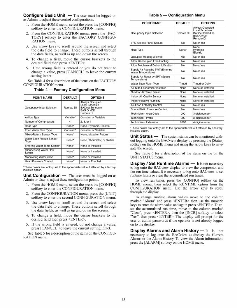
Table 4 — Factory Configuration Menu
*These points are factory set to the appropriate value if affected by a factory-installed option.
Unit Configuration — The user must be logged on asAdmin or User to adjust these configuration points.
1. From the HOME menu, select the press the [CONFIG]softkey to enter the CONFIGURATION menu.
2. From the CONFIGURATION menu, press the [UNIT]softkey to enter the second CONFIGURATION menu.
3. Use arrow keys to scroll around the screen and selectthe data field to change. These buttons scroll throughthe data fields, as well as up and down the screen.
4. To change a field, move the cursor brackets to thedesired field then press <ENTER>.
5. If the wrong field is entered, do not change a value,press [CANCEL] to leave the current setting intact.
See Table 5 for a description of the items on the CONFIGU-RATION menu.
Table 5 — Configuration Menu
*These points are factory set to the appropriate value if affected by a factory-installed option.
Unit Status — The system status can be monitored with-out logging onto the BACview display by pressing the [Status]softkey on the HOME menu and using the arrow keys to navi-gate the screen.
See Table 6 for a description of the items on the on theUNIT STATUS menu.
Display / Set Runtime Alarms — It is not necessaryto log onto the BACview display to view the compressor andfan run time values. It is necessary to log onto BACview to setruntime limits or clear the accumulated run times.
To view run times, press the [CONFIG] softkey on theHOME menu, then select the RUNTIME option from theCONFIGURATION menu. Use the arrow keys to scrollthrough the display.
To change runtime alarm values move to the columnmarked "Alarm" and press <ENTER> then use the numerickeys to enter the alarm value and again press <ENTER>. To re-set the accumulated run time, move to the column marked"Clear", press <ENTER>, then the [INCR] softkey to select"Yes", then press <ENTER>. The display will prompt for theuser or admin passwords if the operator is not already loggedon to the display.
Display Alarms and Alarm History — It is notnecessary to log onto the BACview to display the CurrentAlarms or the Alarm History. To view the Alarm information,press the [ALARM] softkey on the HOME menu.
POINT NAME DEFAULT OPTIONS
Occupancy Input Selection Remote DI
Always OccupiedLocal ScheduleBACnet ScheduleBAS On/OffRemote DI
Airflow Type Variable* Constant or Variable
Number of Compressors 4* 2, 3, or 4
Heat Type None* None, Hydronic, Electric
Econ Water Flow Type Constant* Constant or Variable
Mixed/Return Sensor Type None* None, Mixed or Return
Water Econ Freeze Sensor Type None* None, Thermistor, or Switch
Entering Water Temp Sensor None* None or Installed
(Condenser) Water Flow Switch None* None or Installed
Modulating Water Valve None* None or Installed
Head Pressure Control None* None or Enabled
POINT NAME DEFAULT OPTIONS
Occupancy Input Selection Remote DI
Always OccupiedLocal ScheduleBACnet ScheduleBAS On/OffRemote DI
VFD Access Panel Secure No No or Yes
Heat Type None*NoneHydronicElectric
Occupied Heating Allowed Yes No or Yes
Allow Unoccupied Free Cooling No No or Yes
Allow Mechanical Dehumidification No No or Yes
Supply Air Reset by EWT (Entering Water Temperature) No No or Yes
Supply Air Reset by SPT (Space Temperature) No No or Yes
Water Econ Flush Type Timed Timed or Daily
Air-Side Economizer Installed None None or Installed
Outdoor Air Temp Sensor None None or Installed
Indoor Air Quality Sensor None None or Installed
Indoor Relative Humidity None None or Installed
Air-Econ Enthalpy Control No No or Yes
Space Static Pressure Control No No or Yes
Technician - Area Code 000 3-digit number
Technician - Prefix 000 3-digit number
Technician - Extension 0000 4-digit number
14
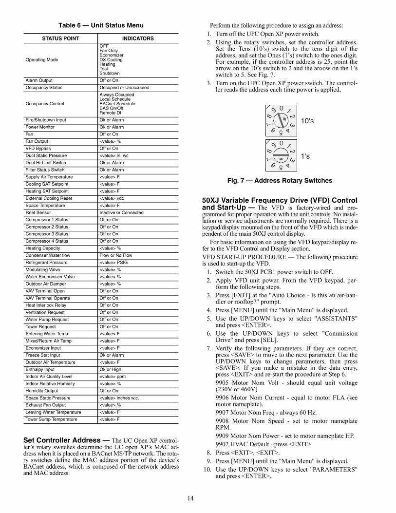
Table 6 — Unit Status Menu
Set Controller Address — The UC Open XP control-ler’s rotary switches determine the UC open XP’s MAC ad-dress when it is placed on a BACnet MS/TP network. The rota-ry switches define the MAC address portion of the device’sBACnet address, which is composed of the network addressand MAC address.
Perform the following procedure to assign an address:1. Turn off the UPC Open XP power switch.2. Using the rotary switches, set the controller address.
Set the Tens (10’s) switch to the tens digit of theaddress, and set the Ones (1’s) switch to the ones digit.For example, if the controller address is 25, point thearrow on the 10’s switch to 2 and the aroow on the 1’sswitch to 5. See Fig. 7.
3. Turn on the UPC Open XP power switch. The control-ler reads the address each time power is applied.
50XJ Variable Frequency Drive (VFD) Controland Start-Up — The VFD is factory-wired and pro-grammed for proper operation with the unit controls. No instal-lation or service adjustments are normally required. There is akeypad/display mounted on the front of the VFD which is inde-pendent of the main 50XJ control display.
For basic information on using the VFD keypad/display re-fer to the VFD Control and Display section.VFD START-UP PROCEDURE — The following procedureis used to start-up the VFD.
1. Switch the 50XJ PCB1 power switch to OFF.2. Apply VFD unit power. From the VFD keypad, per-
form the following steps.3. Press [EXIT] at the "Auto Choice - Is this an air-han-
dler or rooftop?" prompt.4. Press [MENU] until the "Main Menu" is displayed.5. Use the UP/DOWN keys to select "ASSISTANTS"
and press <ENTER>.6. Use the UP/DOWN keys to select "Commission
Drive" and press [SEL].7. Verify the following parameters. If they are correct,
press <SAVE> to move to the next parameter. Use theUP/DOWN keys to change parameters, then press<SAVE>. If you make a mistake in the data entry,press <EXIT> and re-start the procedure at Step 6.9905 Motor Nom Volt - should equal unit voltage(230V or 460V)9906 Motor Nom Current - equal to motor FLA (seemotor nameplate).9907 Motor Nom Freq - always 60 Hz.9908 Motor Nom Speed - set to motor nameplateRPM.9909 Motor Nom Power - set to motor nameplate HP.9902 HVAC Default - press <EXIT>
8. Press <EXIT>, <EXIT>.9. Press [MENU] until the "Main Menu" is displayed.
10. Use the UP/DOWN keys to select "PARAMETERS"and press <ENTER>.
STATUS POINT INDICATORS
Operating Mode
OFFFan OnlyEconomizerDX CoolingHeatingTestShutdown
Alarm Output Off or On
Occupancy Status Occupied or Unoccupied
Occupancy Control
Always OccupiedLocal ScheduleBACnet ScheduleBAS On/OffRemote DI
Fire/Shutdown Input Ok or Alarm
Power Monitor Ok or Alarm
Fan Off or On
Fan Output <value> %
VFD Bypass Off or On
Duct Static Pressure <value> in. wc
Duct Hi-Limit Switch Ok or Alarm
Filter Status Switch Ok or Alarm
Supply Air Temperature <value> F
Cooling SAT Setpoint <value> F
Heating SAT Setpoint <value> F
External Cooling Reset <value> vdc
Space Temperature <value> F
Rnet Sensor Inactive or Connected
Compressor 1 Status Off or On
Compressor 2 Status Off or On
Compressor 3 Status Off or On
Compressor 4 Status Off or On
Heating Capacity <value> %
Condenser Water flow Flow or No Flow
Refrigerant Pressure <value> PSIG
Modulating Valve <value> %
Water Economizer Valve <value> %
Outdoor Air Damper <value> %
VAV Terminal Open Off or On
VAV Terminal Operate Off or On
Heat Interlock Relay Off or On
Ventilation Request Off or On
Water Pump Request Off or On
Tower Request Off or On
Entering Water Temp <value> F
Mixed/Return Air Temp <value> F
Economizer Input <value> F
Freeze Stat Input Ok or Alarm
Outdoor Air Temperature <value> F
Enthalpy Input Ok or High
Indoor Air Quality Level <value> ppm
Indoor Relative Humidity <value> %
Humidity Output Off or On
Space Static Pressure <value> inches w.c.
Exhaust Fan Output <value> %
Leaving Water Temperature <value> F
Tower Sump Temperature <value> F
10's
1's
1
3
45
2
78
9
6
0
13
45
2
78
9
6
0
Fig. 7 — Address Rotary Switches
a48-8578
15
11. Use the UP/DOWN keys to select "20 Limits" andpress [SEL].
12. Use the UP/DOWN keys to select "2003 Max Current"and press [EDIT].
13. Set equal to the motor nameplate FLA * Service Fac-tor; press [SAVE]. If not possible, set the drive to themotor FLA. If that is not possible, STOP immediatelyand call engineering support.
14. Press [EXIT] repeatedly until the drive returns to"PARAMETER" screen.
15. Use the UP/DOWN keys to select "26 Motor Control"and press [SEL].
16. Use the UP/DOWN keys to select "2606 SwitchingFreq" and press [EDIT].
17. Use the UP/DOWN keys to select "8 kHz" and press[SAVE].
18. Press [EXIT] repeatedly until the drive returns to"PARAMETER" screen.
19. Use the UP/DOWN keys to select "16 System Con-trols" and press [SEL].
20. Use the UP/DOWN keys to select "1601 - RunEnable" and press [EDIT].
21. Use the UP/DOWN keys to select "NOT SEL" andpress [SAVE].
22. Use UP/DOWN keys to select "1608 - Start Enable 1"and press [EDIT].
23. Use UP/DOWN keys to select "NOT SEL" and press[SAVE].
24. Press [EXIT] repeatedly until the drive returns to themonitor screen and displays Hz, Amps, etc.
25. Switch 50XJ PCB1 power switch to ON.
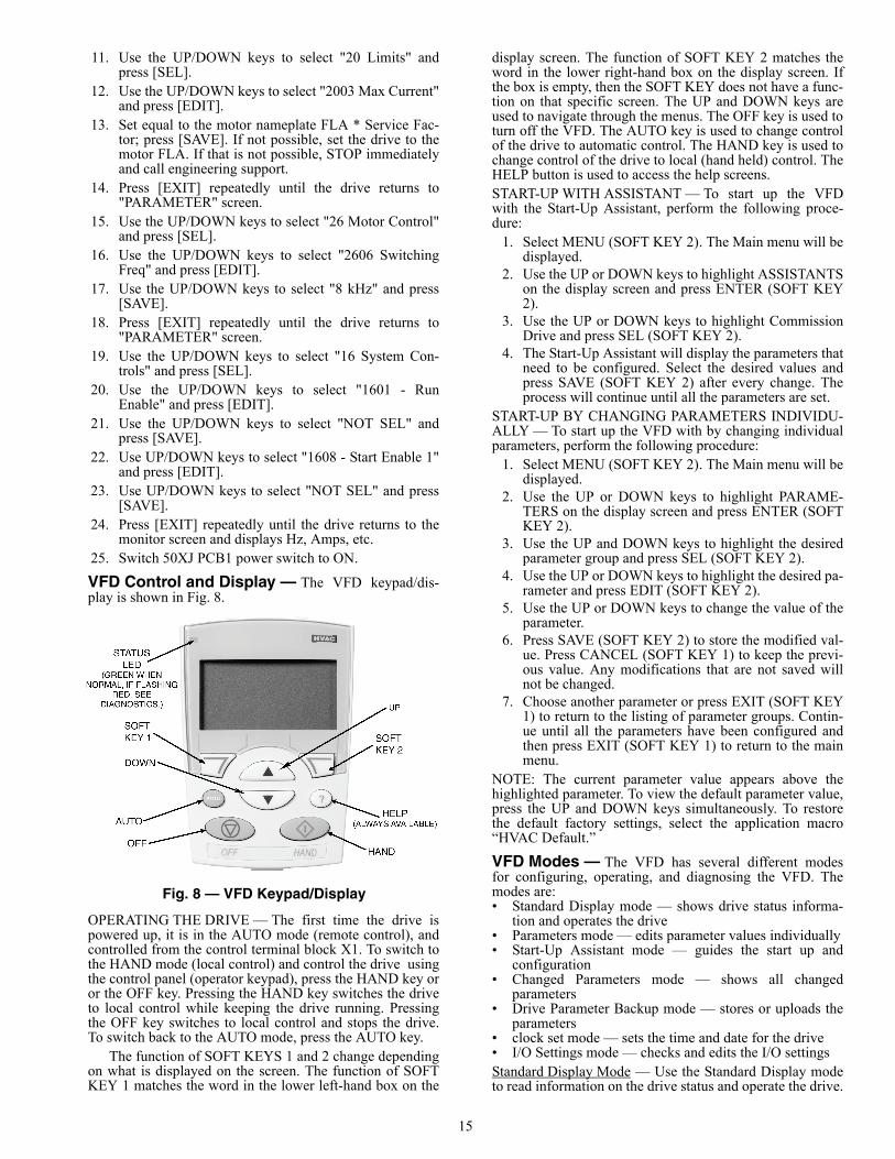
VFD Control and Display — The VFD keypad/dis-play is shown in Fig. 8.
OPERATING THE DRIVE — The first time the drive ispowered up, it is in the AUTO mode (remote control), andcontrolled from the control terminal block X1. To switch tothe HAND mode (local control) and control the drive usingthe control panel (operator keypad), press the HAND key oror the OFF key. Pressing the HAND key switches the driveto local control while keeping the drive running. Pressingthe OFF key switches to local control and stops the drive.To switch back to the AUTO mode, press the AUTO key.
The function of SOFT KEYS 1 and 2 change dependingon what is displayed on the screen. The function of SOFTKEY 1 matches the word in the lower left-hand box on the
display screen. The function of SOFT KEY 2 matches theword in the lower right-hand box on the display screen. Ifthe box is empty, then the SOFT KEY does not have a func-tion on that specific screen. The UP and DOWN keys areused to navigate through the menus. The OFF key is used toturn off the VFD. The AUTO key is used to change controlof the drive to automatic control. The HAND key is used tochange control of the drive to local (hand held) control. TheHELP button is used to access the help screens.START-UP WITH ASSISTANT — To start up the VFDwith the Start-Up Assistant, perform the following proce-dure:
1. Select MENU (SOFT KEY 2). The Main menu will bedisplayed.
2. Use the UP or DOWN keys to highlight ASSISTANTSon the display screen and press ENTER (SOFT KEY2).
3. Use the UP or DOWN keys to highlight CommissionDrive and press SEL (SOFT KEY 2).
4. The Start-Up Assistant will display the parameters thatneed to be configured. Select the desired values andpress SAVE (SOFT KEY 2) after every change. Theprocess will continue until all the parameters are set.
START-UP BY CHANGING PARAMETERS INDIVIDU-ALLY — To start up the VFD with by changing individualparameters, perform the following procedure:
1. Select MENU (SOFT KEY 2). The Main menu will bedisplayed.
2. Use the UP or DOWN keys to highlight PARAME-TERS on the display screen and press ENTER (SOFTKEY 2).
3. Use the UP and DOWN keys to highlight the desiredparameter group and press SEL (SOFT KEY 2).
4. Use the UP or DOWN keys to highlight the desired pa-rameter and press EDIT (SOFT KEY 2).
5. Use the UP or DOWN keys to change the value of theparameter.
6. Press SAVE (SOFT KEY 2) to store the modified val-ue. Press CANCEL (SOFT KEY 1) to keep the previ-ous value. Any modifications that are not saved willnot be changed.
7. Choose another parameter or press EXIT (SOFT KEY1) to return to the listing of parameter groups. Contin-ue until all the parameters have been configured andthen press EXIT (SOFT KEY 1) to return to the mainmenu.
NOTE: The current parameter value appears above thehighlighted parameter. To view the default parameter value,press the UP and DOWN keys simultaneously. To restorethe default factory settings, select the application macro“HVAC Default.”
VFD Modes — The VFD has several different modesfor configuring, operating, and diagnosing the VFD. Themodes are:• Standard Display mode — shows drive status informa-
tion and operates the drive• Parameters mode — edits parameter values individually• Start-Up Assistant mode — guides the start up and
configuration• Changed Parameters mode — shows all changed
parameters• Drive Parameter Backup mode — stores or uploads the
parameters• clock set mode — sets the time and date for the drive• I/O Settings mode — checks and edits the I/O settingsStandard Display Mode — Use the Standard Display modeto read information on the drive status and operate the drive.
Fig. 8 — VFD Keypad/Display
a39-2918
16
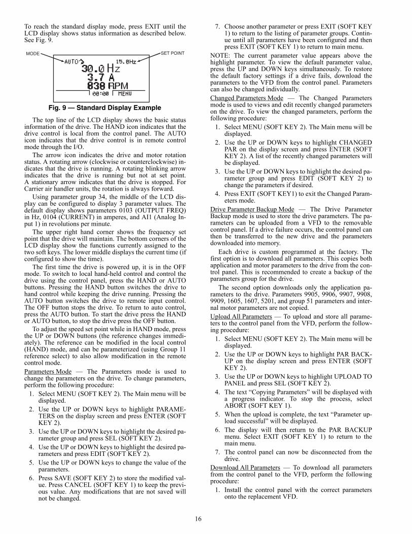
To reach the standard display mode, press EXIT until theLCD display shows status information as described below.See Fig. 9.
The top line of the LCD display shows the basic statusinformation of the drive. The HAND icon indicates that thedrive control is local from the control panel. The AUTOicon indicates that the drive control is in remote controlmode through the I/O.
The arrow icon indicates the drive and motor rotationstatus. A rotating arrow (clockwise or counterclockwise) in-dicates that the drive is running. A rotating blinking arrowindicates that the drive is running but not at set point.A stationary arrow indicates that the drive is stopped. ForCarrier air handler units, the rotation is always forward.
Using parameter group 34, the middle of the LCD dis-play can be configured to display 3 parameter values. Thedefault display shows parameters 0103 (OUTPUT FREQ)in Hz, 0104 (CURRENT) in amperes, and AI1 (Analog In-put 1) in revolutions per minute.
The upper right hand corner shows the frequency setpoint that the drive will maintain. The bottom corners of theLCD display show the functions currently assigned to thetwo soft keys. The lower middle displays the current time (ifconfigured to show the time).
The first time the drive is powered up, it is in the OFFmode. To switch to local hand-held control and control thedrive using the control panel, press the HAND or AUTObuttons. Pressing the HAND button switches the drive tohand control while keeping the drive running. Pressing theAUTO button switches the drive to remote input control.The OFF button stops the drive. To return to auto control,press the AUTO button. To start the drive press the HANDor AUTO button, to stop the drive press the OFF button.
To adjust the speed set point while in HAND mode, pressthe UP or DOWN buttons (the reference changes immedi-ately). The reference can be modified in the local control(HAND) mode, and can be parameterized (using Group 11reference select) to also allow modification in the remotecontrol mode.Parameters Mode — The Parameters mode is used tochange the parameters on the drive. To change parameters,perform the following procedure:
1. Select MENU (SOFT KEY 2). The Main menu will bedisplayed.
2. Use the UP or DOWN keys to highlight PARAME-TERS on the display screen and press ENTER (SOFTKEY 2).
3. Use the UP or DOWN keys to highlight the desired pa-rameter group and press SEL (SOFT KEY 2).
4. Use the UP or DOWN keys to highlight the desired pa-rameters and press EDIT (SOFT KEY 2).
5. Use the UP or DOWN keys to change the value of theparameters.
6. Press SAVE (SOFT KEY 2) to store the modified val-ue. Press CANCEL (SOFT KEY 1) to keep the previ-ous value. Any modifications that are not saved willnot be changed.
7. Choose another parameter or press EXIT (SOFT KEY1) to return to the listing of parameter groups. Contin-ue until all parameters have been configured and thenpress EXIT (SOFT KEY 1) to return to main menu.
NOTE: The current parameter value appears above thehighlight parameter. To view the default parameter value,press the UP and DOWN keys simultaneously. To restorethe default factory settings if a drive fails, download theparameters to the VFD from the control panel. Parameterscan also be changed individually.Changed Parameters Mode — The Changed Parametersmode is used to views and edit recently changed parameterson the drive. To view the changed parameters, perform thefollowing procedure:
1. Select MENU (SOFT KEY 2). The Main menu will bedisplayed.
2. Use the UP or DOWN keys to highlight CHANGEDPAR on the display screen and press ENTER (SOFTKEY 2). A list of the recently changed parameters willbe displayed.
3. Use the UP or DOWN keys to highlight the desired pa-rameter group and press EDIT (SOFT KEY 2) tochange the parameters if desired.
4. Press EXIT (SOFT KEY1) to exit the Changed Param-eters mode.
Drive Parameter Backup Mode — The Drive ParameterBackup mode is used to store the drive parameters. The pa-rameters can be uploaded from a VFD to the removablecontrol panel. If a drive failure occurs, the control panel canthen be transferred to the new drive and the parametersdownloaded into memory.
Each drive is custom programmed at the factory. Thefirst option is to download all parameters. This copies bothapplication and motor parameters to the drive from the con-trol panel. This is recommended to create a backup of theparameters group for the drive.
The second option downloads only the application pa-rameters to the drive. Parameters 9905, 9906, 9907, 9908,9909, 1605, 1607, 5201, and group 51 parameters and inter-nal motor parameters are not copied.Upload All Parameters — To upload and store all parame-ters to the control panel from the VFD, perform the follow-ing procedure:
1. Select MENU (SOFT KEY 2). The Main menu will bedisplayed.
2. Use the UP or DOWN keys to highlight PAR BACK-UP on the display screen and press ENTER (SOFTKEY 2).
3. Use the UP or DOWN keys to highlight UPLOAD TOPANEL and press SEL (SOFT KEY 2).
4. The text “Copying Parameters” will be displayed witha progress indicator. To stop the process, selectABORT (SOFT KEY 1).
5. When the upload is complete, the text “Parameter up-load successful” will be displayed.
6. The display will then return to the PAR BACKUPmenu. Select EXIT (SOFT KEY 1) to return to themain menu.
7. The control panel can now be disconnected from thedrive.
Download All Parameters — To download all parametersfrom the control panel to the VFD, perform the followingprocedure:
1. Install the control panel with the correct parametersonto the replacement VFD.
MODE SET POINT
Fig. 9 — Standard Display Example
a39-2919
17
2. Select MENU (SOFT KEY 2). The Main menu will bedisplayed.
3. Use the UP or DOWN keys to highlight PAR BACK-UP on the display screen and press ENTER (SOFTKEY 2).
4. Use the UP or DOWN keys to highlight DOWNLOADTO DRIVE ALL and press SEL (SOFT KEY 2).
5. The text “Restoring Parameters” will be displayedwith a progress indicator. To stop the precess, selectABORT (SOFT KEY 1).
6. When the download is complete, the text “Parameterdownload successful” will be displayed.
7. The display will then return to the PAR BACKUPmenu. Select EXIT (SOFT KEY 1) to return to themain menu.
8. The control panel can now be disconnected from thedrive.
Clock Set Mode — The Clock Set mode is used for settingthe date and time for the internal clock of the VFD. In orderto use the timer functions of the VFD control, the internalclock must be set. The date is used to determine weekdaysand is visible in the fault logs.
To set the clock, perform the following procedure:1. Select MENU (SOFT KEY 2). The Main menu will be
displayed.2. Use the UP or DOWN keys to highlight CLOCK SET
on the display screen and press ENTER (SOFT KEY2). The clock set parameter list will be displayed.
3. Use the UP or DOWN keys to highlight CLOCK VIS-IBILITY and press SEL (SOFT KEY 2). This parame-ter is used to display or hide the clock on the screen.Use the UP or DOWN keys to change parameter set-ting. Press OK (SOFT KEY 2) to save the configura-tion and return to the Clock Set menu.
4. Use the UP or DOWN keys to highlight SET TIMEand press SEL (SOFT KEY 2). Use the UP or DOWNkeys to change the hours and minutes. Press OK(SOFT KEY 2) to save the configuration and return tothe Clock Set menu.
5. Use the UP or DOWN keys to highlight TIME FOR-MAT and press SEL (SOFT KEY 2). Use the UP andDOWN keys to change the parameter setting. PressOK (SOFT KEY 2) to save the configuration and re-turn to the Clock Set menu.
6. Use the UP or DOWN keys to highlight SET DATEand press SEL (SOFT KEY 2). Use the UP or DOWNkeys to change the day, month, and year. Press OK(SOFT KEY 2) to save the configuration and return tothe Clock Set menu.
7. Use the UP or DOWN keys to highlight DATE FOR-MAT and press SEL (SOFT KEY 2). Use the UP orDOWN keys to change the parameter setting. PressOK (SOFT KEY 2) to save the configuration and re-turn to the Clock Set menu.
8. Press EXIT (SOFT KEY 1) twice to return to the mainmenu.
I/O Settings Mode — The I/O Settings mode is used forviewing and editing the I/O settings.
To configure the I/O settings, perform the followingprocedure:
1. Select MENU (SOFT KEY 2). The Main menu will bedisplayed.
2. Use the UP or DOWN keys to highlight I/O SET-TINGS on the display screen and press ENTER (SOFTKEY 2). The I/O Settings parameter list will be dis-played.
3. Use the UP or DOWN keys to highlight the desired I/O setting and press SEL (SOFT KEY 2).
4. Use the UP or DOWN keys to select the parameter toview. Press OK (SOFT KEY 2).
5. Use the UP or DOWN keys to change the parametersetting. Press SAVE (SOFT KEY 2) to save the config-uration. Press CANCEL (SOFT KEY 1) to keep theprevious value. Any modifications that are not savedwill not be changed.
6. Press EXIT (SOFT KEY 1) twice to return to the mainmenu.
OPERATION
Occupancy Determination — The Omnizone™controller allows several methods of occupancy determination,based upon the setting of the occupancy configuration. Localoccupancy is determined by either a local schedule (LocalSched) contained in the controller, the use of the ROCC dis-crete input point (Remote DI) or by setting the unit configura-tion to always occupied (Always Occ).
When the Omnizone unit is connected to a network, occu-pancy can be controlled the occupancy configuration. To oper-ate to a BACnet schedule, set the configuration to "BACnetSched." To use a remote On/Off signal from a building automa-tion system, set the configuration to "BAS On/Off."
Fan Control — All variable air volume (VAV) units have avariable frequency drive (VFD) to provide variable fan motorspeed and thus variable airflow. Fan control turns the fan onand off based on unit operating mode, and controls fan speed tomaintain a particular duct static pressure at a duct static pres-sure (DSP) sensor. The objective is to maintain a reasonablyconstant supply-air exit velocity at VAV system outlet grilles,regardless of damper opening positions. The duct static pres-sure sensor is field-installed about 2/3 of the way toward the"far end" of the ductwork. A high duct static (DHS) switch pro-vides protection by shutting the fan down if the duct static pres-sure exceeds a maximum setting.
For the 50XJ unit, a VFD interface display is mounted inthe front of the unit. A number of user-adjustable features canbe entered/changed using the keypad on the display. These fea-tures are described in detail in the Variable Frequency DriveControl section.
Sequence of Operation — The following controlsequence of operation for the 50XJ unit describes the varioussequences that occur depending upon the way an operation istriggered and which software control points are involved.SUPPLY FAN — The supply fan is enabled whenever the unitenters occupied mode. The fan is also enabled in the unoccu-pied mode with a cooling or heating demand. Fan operationwill be prevented if there is an active duct high static pressurealarm, the optional phase rotation monitor indicates a problem,the duct static pressure sensor has failed or has an alarm, orthere is a fire/smoke shutdown alarm.
When there are no alarms preventing fan operation and thefan is enabled, the (remote terminal control) TRMCT shouldturn on. 30 seconds later the output to the VFD will increase.The VFD output level is determined by a PID calculation,based on the duct static pressure (DSP) input and the supplystatic pressure setpoint. Once the supply fan is running and thestatic pressure increases above the Supply fan status setpointthe supply fan status point (SFS) will indicate ON.
18
The space temperature sensor point (sptsens) indicates thecurrent value of the sensor used to determine cooling/heatingdemand. The sensor selection is based on the sensors installedand the configuration of these sensors in the custom configura-tion. The following sensors, when valid, are used for the spacetemperature sensor with the highest precedence at the top of thelist:• Space temperature sensor (SPT)• Return air temperature sensor (MA_RA) - only used if
the unit is NOT configured for reset by EWT.• Entering water temperature (EWT) - only if the unit is
configured for reset by EWT.• Default with no sensors is the occupied cooling setpoint
of 10 F (prevents unoccupied operation).If the space has unoccupied demand, the supply fan is en-
abled. If conditions allow, the fan will start as described above.If the fan is running due to unoccupied heating or cooling de-mand, the controlling temperature input must rise or drop towithin half way between the occupied and unoccupied set-points in order for the fan to turn back off.
Once the unoccupied conditions are satisfied, there is afixed 5-minute delay for normal fan shutdown. During the 5-minute delay, the cooling and heating routines become dis-abled. This delay allows a compressor that may have just start-ed to run for its 5-minute minimum on-time with the supply fanon. For example, if the staging routine had just started com-pressor no. 3 at the time the call was satisfied, the cooling rou-tine would become disabled and compressor no. 1 and 2 wouldshut off right away. Compressor no. 3 would continue to runfor its minimum on time of 5 minutes. The fan continues run-ning until all compressors meet the minimum on time and runwith a load, preventing them from shutting down due to asafety.Supply Fan operation with Optional Bypass — If the option-al VFD bypass is installed and the bypass switch has beenturned to bypass (line), and the VFD compartment access panelis in place, the software point VFD Access Panel Secure hasbeen set to YES, there are no faults to prevent fan operationand there is a call for fan operation, then the bypass start stoppoint BPS_S will be engaged to start the fan. The terminalopen point TRMOP will go on with the TRMCT point 30 sec-onds before the fan starts.COMPRESSOR COOLING — If the fan is on and there is nodemand for heat, internal software point (COOLOK) willswitch to on. The unit MODE will not change to "Cooling" unitthere is an active call for compressor operation.
If the unit is configured for variable flow the reverse/headpressure control valve will open (otherwise it will already beopen), and if there is condenser water flow (or no flow switchinstalled), then mechanical cooling will be enabled.
Units are equipped with 2, 3, or 4 compressors piped in sep-arate refrigerant circuits, and staged on/off in a fixed sequentialmanner (compressor no. 1 through compressor no. 4). Thecompressor control routine uses a PID calculation to determinethe percentage of cooling required, from 1 to 100%. Demandfor the PID calculation is determined from the supply air tem-perature and the supply air set point.
Compressor cooling will be disabled for any of the follow-ing reasons:• There is no water flow (CDWF is off, with switch
installed).• Economizer freezestat (FREEZ) has been in alarm for
more than 15 minutes.• MODE changes to heat.• OK-FAN turns off during normal shut down.
During normal compressor operation the minimum on timeis 5 minutes and the minimum off time is 5 minutes.
ECONOMIZER COOLING — The unit diverts condenserinlet water flow through an optional economizer coil to precoolevaporator entering airflow. This occurs when there is demandfor the cooling, and the temperature at an entering water tem-perature (EWT) thermistor is colder than the economizer startset point. Water flow is controlled via two electronic waterflow valves. This option also incorporates an economizerfreeze sensor or switch (economizer temperature/freeze stat),located at the inlet of the economizer coil.
Economizer water flow is in series with the condensersallowing compressor operation while the economizer isoperating.
The equipment mode will change to "Free Cooling" if thereis no call for compressor operation, the fan is on, and there isno demand for heat. If the unit is configured for variable flowthe reverse head pressure control valve will open (otherwise itwill already be open), and if there is condenser water flow, theneconomizer cooling is enabled.
If the entering-water temperature is below the economizerset point then the Mod. Econ Enabled point (ECONOK) willchange to enable and the economizer valve will modulate opento lower the economizer control temperature to the supply airset point temperature. The economizer modulation is con-trolled by a PID loop and the reverse/head pressure controlvalve will modulate in reverse of the Economizer valve usingthe formula MVLV = 100 - ECONO.COOLING RESET — The controller can reset the supply airset point using these two methods:• An external 0 to 10 volt input RESET• The value of the space control point
The external 0 to 10 volt input reset is configured to producea 0 to 20 degree supply air reset over the 2 to 10 volt range. Ifmore than 1.8 volts is sensed on the input, this method of resettakes priority over other methods.NOTE: The reset from all methods may be limited from 0 to20 F by the Maximum Reset Setpoint.
The return air sensor, space temperature sensor, or enteringwater temperature input will be used as the space control point.If this control input goes below the Occupied Cooling setpoint,then for each degree that the point is below the set point valuethe supply air set point will be reset by the value configured inthe RESET RATIO set point.HEATING — The controller is configured to control either ahot water/steam valve or electric heat through a modulating0 to 10 vdc output. A field-supplied and installed step sequenc-er can convert the modulating signal into two, four, or morediscrete stages of control for non-SCR electric heat control.
For either method of heat to function, a space control pointmust be configured in the custom configuration. This controlpoint comes from a return air sensor or space sensor, or the en-tering water temperature sensor.
Whenever the space control point is below the occupied orunoccupied heat set point the mode will change to heat and ifunoccupied the fan will be started. The heat control routineuses a PID to control the heating output to maintain the supplyair set point.
When unoccupied heat is enabled the fan will be stoppedand the heat turned off when the space control temperature ismore than halfway above the difference between the occupiedheat set point and the unoccupied heat setpoint. For example, ifthe occupied heat set point is 70 and the unoccupied heat setpoint is 60 the unit will come on for unoccupied heating below60 F and turn off again above 65 F.HEAD PRESSURE CONTROL (HPC) — In installationswhere entering water temperature can fall below 55 F, where awater economizer (described above) is not installed, the HPCprovides an electronic water flow control valves to vary flow tothe condensers. Controlling the water flow maintains
19
compressor discharge pressure above a minimum value, ensur-ing sufficient refrigerant flow out of the condenser andthroughout the refrigerant circuit. Refrigerant pressure is mea-sured at compressor circuit no. 1 by a discharge pressure sensor(PRES).
The 50XJ units not equipped with a water economizer canbe ordered with the reverse/head pressure control valve factoryinstalled and a pressure transducer located in the discharge lineof compressor no. 1.
When the unit is operating, cooling is enabled, a compressoris engaged, and the entering water temperature falls below60 F, head pressure control will be enabled. The head pressurecontrol valve will modulate to keep the head pressure at the Re-frigerant Head Pressure set point. The default set point is225 PSI and may be set from 200 to 300 PSI. The minimumoutput value for the head pressure control algorithm is 40% inorder to maintain a minimum flow through the condensers. Thevalve will modulate between 40 and 100%.VENTILATION REQUEST — The ventilation request out-put will close a set of relay contacts to activate a ventilationdamper whenever the supply fan and supply fan status are bothtrue and the unit status is occupied or override.VAV TERMINAL OPERATION OUTPUT — The VAVterminal control output (TRMCT) closes a set of relay contactsto indicate to non-Carrier air terminals that the fan is on and op-eration has been verified. This signals the terminals to open andstart controlling to the desired CFM and temperature set points.VAV TERMINAL OPEN OUTPUT — The VAV terminalopen output (TRMOP) closes a set of relay contacts to com-mand the air terminals to open to maximum CFM at timeswhen the fan is operating on the VFD bypass. This contact willclose 30 seconds before the supply starts in bypass mode.PUMP OUTPUT — The pump output closes a set of relaycontacts to indicate that the 50XJ unit is in operation and mayrequire condenser water flow through the unit. This contact isclosed when the unit is not in heating mode and the supply fanis operating. This contact is also close if the economizer freezecontrols (described above) detects unacceptable conditionswith the unit configured without an air economizer or headpressure control.TOWER OUTPUT — The tower output closes a set of relaycontacts to start/stop tower controls. This contact closes whenthe unit is not in heating mode and the supply fan is operating.BUILDING PRESSURE CONTROL — The building pres-sure control output provides an analog 0 to 10 vdc signal tocontrol return fan or exhaust fan speed. Fan speed is modulatedto maintain the building static pressure set point.
The control parameters for the building pressure set pointand building pressure are read and controlled in voltage but areconverted to inches of water for ease of setting and display. Therange and low start values of the sensor selected should be con-figured in the setpoint screen, after the use of space static pres-sure sensor has been enabled on the configuration screen.
Diagnostic Features — The controller and BACviewdisplay provide a number of features to help protect the unitand allow problem diagnosis.CRITICAL FAULT — The controller provides an output (forfield connection) to signal an external building systems moni-tor or control that the unit has a critical alarm that may be im-pacting unit operation. The alarm lamp on the BACview dis-play provides visual indication of this condition.
The BACview display allows the user to monitor alarmsand determine sensor input values.FIRE INPUT (FSD) — This is a normally closed input con-nected to the controller. When this input is opened, all controloutputs are immediately turned off, including the fan.
DUCT HIGH STATIC INPUT (DHS) — This differential airpressure switch provides backup protection for the ductwork. Itis factory installed in the unit and wired to the unit controller.This switch has a manually adjustable set point with a range of1 to 5 in. wc. Upon switch closure, the controller immediatelyturns all outputs off, including fan, and then indicates an alarmboth by turning on its alarm output, the BACview alarm lampand via communications (if used).DIRTY FILTERS SWITCH (FLTS) — This is a factory-in-stalled option on the 50XJ unit. This input is used to connect apressure switch that measures the air pressure difference acrossthe filters. When the delta increases beyond the preset setting, adirty filter alarm is activated, indicating that the filters needcleaning or replacement.
The switch is normally open, with manually adjustable set-ting at the switch between 0.5 and 1.5 in. wc. Upon closure,controller holds the alarm for 1 minute to assure that the condi-tion is stable and then it activates the alarm. Beyond the alarm,the dirty filter condition does not affect controller operation, sothe unit should operate normally.COMPRESSOR OVERLOAD (COL)/SAFETIES — Eachcompressor is provided with either an internal line-break over-current protector or an external overload protection module.Each compressor control circuit also contains a compressor lock-out board (CLO), high-pressure switch (HPS), low-pressureswitch (LPS), and evaporator freeze switch (FRZ). Except forthe internal line-break protection, these devices are wired in se-ries to the contactor for each compressor. A pilot relay is wired inparallel with the compressor contactor to determine when thecompressor contactor is energized/de-energized.
The compressor lockout board (CLO) is located in the unitcontrol box, wired in the control line for the compressor contac-tor, and incorporates a current loop which monitors one leg of thecompressor power leads. This board is powered along with therelated compressor contactor.
Whenever the compressor current falls below a threshold lev-el (i.e., compressor not operating) on an energized circuit, thelockout board activates an on-board relay which opens power tothe compressor contactor and pilot relay. The pilot relay contactssignal the controller with the compressor status. If any of thesafety devices described above opens, the compressor shutdownsequence is started. In the event this occurs, the controller shouldturn off this compressor, and start the next compressor in se-quence. After a 5-minute period, the controller should restart thiscompressor, and turn the other one off, as cooling demand re-quires. If the “problem” compressor then operates for 10 minutesof run time normally, the unit reverts to normal operation andcompressor sequencing. If not, and the same error occurs again,this compressor should be shut down and replaced with the nextcompressor, as before, and held off for 10 minutes. It should thenbe restarted and the other compressor shut down, as before. If itdoes not run successfully for 10 minutes of normal run timeagain, it is shut down and replaced a third time. This time it isheld off for 15 minutes. If the "problem" compressor does notoperate successfully for the 10 minutes of normal run time thisthird time, this compressor ONLY is shut down and locked outfor servicing. A compressor lockout alarm is generated and theBACview alarm lamp is turned on.HIGH-PRESSURE SWITCH (HPS) — This switch is locatedin the discharge refrigerant line of each compressor, and is setto open at pressures above 360 psig (R-22) and 570 psig(R-410A). It is wired in the 24-vac control power line of thecompressor contactor (in series with the LPS and FRZ) anddisables compressor operation when it opens.LOW-PRESSURE SWITCH (LPS) — The low-pressureswitch (LPS) is located in the suction refrigerant line of eachcompressor, and is set to open at pressures below 27 psig. TheLPS is wired in the 24-vac control power line of the
20
compressor contactor (in series with the HPS and FRZ) anddisables compressor operation when it opens.EVAPORATOR FREEZE SWITCH (FRZ) — The evaporatorfreeze switch (FRZ) is a thermal disk type switch, mounted ona return bend of the evaporator, refrigerant circuit for whichcorresponds to each respective compressor, and is set to open attemperatures below 28 F. The FRZ is wired in the 24-vac con-trol power line of the compressor contactor (in series with theLPS and HPS) and disables compressor operation when itopens.COMPRESSOR EXTERNAL OVERLOAD PROTEC-TION MODULE — This board is provided with each com-pressor that does not include internal line-break overload pro-tection. When installed, this board is in the compressor termi-nal box. This board activates at an over temperature setting,and locks out operation of the compressor for 30 minutes; thereis no method to over-ride or reset this timer. Due to this timingfunction, please note that the compressor will not attempt to re-start until the third attempt described above.COMPRESSOR INTERNAL LINE-BREAK OVERLOADPROTECTION MODULE — Some compressors are builtwith internal line-break protection. When the winding tempera-ture exceeds the protector setting, the protector opens two ofthe three power lines within the compressor. This protectorkeeps the compressor locked out until the winding temperaturefalls below the protectors reset temperature. There is no meth-od to override or reset this protector, except by lowering thewinding temperature. Under some circumstances, the compres-sor may not attempt to restart until the third attempt describedabove.ALARMS — There are four methods to annunciate alarms:BACview alarm lamp, BACview alarm display, network com-munications, or the discreet alarm output dry contacts. Alarmsare covered in detail in the Troubleshooting section.
TROUBLESHOOTING
Standard Diagnostic Features, Alarms andAlarm Lamps — Unit reset of alarm failure operation isautomatic when fault is cleared, except as noted. SUPPLY AIR TEMPERATURE ALARM — If supply airtemperature input falls outside the range of 25 to 150 F, thealarm output will close and the red alarm lamp will be lit. Analarm with an ID of "sat_alarm" will be generated, but the unitwill operate normally.SUPPLY AIR TEMPERATURE SENSOR FAILURE — Ifthe supply air temperature sensor fails the system will display asupply air temperature of 0.00 F, the compressor outputs willbe disabled, the alarm output will close and the red alarm lampwill be lit. An alarm with an ID of "sat_sen_alarm" will begenerated.DUCT STATIC PRESSURE ALARM — If the duct staticpressure input falls outside the range of 0.06 to 5.45 in. wc, thealarm output will close and the red alarm lamp will be lit. Analarm with an ID of "dsp_alarm" will be generated, but the unitwill operate normally.DUCT STATIC PRESSURE SENSOR FAILURE — If theduct static pressure sensor fails, the system will display 0.00 in.wc, the controller outputs will be forced off, the alarm outputwill close and the red alarm lamp will be lit. An alarm with anID of "dsp_sens_alarm" will be generated.DUCT HIGH STATIC INPUT (DHS) — This factory-installed air switch provides over pressurization protection forthe ductwork. The switch is a normally open switch, with ad-justable manual setting (range is 1 to 5 in. wc with a default of3.0 in. wc). Upon switch closure, the controller outputs will beforced off, the alarm output will close and the red alarm lampwill be lit. An alarm with an ID of "dhs_alarm" will begenerated.
FIRE/SHUTDOWN INPUT (FSD) — This is a normallyclosed input, which when opened, all control outputs are im-mediately turned off, including the fan, the alarm output willclose and the red alarm lamp will be lit. An alarm with an ID of"fire_alarm" will be generated.CONDENSER WATER FLOW (CDWF) — This is an op-tional switch that can be used with the Omnizone™ controller.A thermal dispersion flow switch detects water flowing pastthe sensor element and closes normally open contacts that ener-gize a relay with normally open contacts to the unit controller.A configuration set point is used to indicate if this switch is in-stalled and disable alarms from the flow switch. When the flowswitch is installed, the controller will check for water flowwhen flow is requested for unit operation and if flow is not de-tected, compressor operation will be disabled. The controllerwill also test or to see if there is water flow when the unit is notoperating. If there is no flow when the unit is operating or ifthere is flow when the unit is not operating, the alarm outputwill close and the red alarm lamp will be lit. An alarm with anID of "cdwf_alrm" will be generated.DIRTY FILTERS SWITCH INPUT (DFS) — This optionalair pressure switch may be factory-installed in the 50XJ unit todetect the pressure differential pressure across the return air fil-ters. This switch is normally open, with manually adjustablesetting at the switch between 0.5 and 1.5 in. wc. Upon closure,controller should wait to assure closure for minimum 1 minute,and then the alarm output will close and the red alarm lampwill be lit. An alarm with an ID of "flts_alarm" will be generat-ed. However, all other unit operation should remain normal.PHASE LOSS/REVERSAL INPUT (PRM) — A powermonitor may be installed in the unit to detect over-voltage, un-der-voltage conditions, phase loss and/or phase reversal. Uponswitch closure a pilot relay is engaged and the input to the con-troller is closed. In adverse power conditions, all controller out-puts will be forced off, the alarm output will close and the redalarm lamp will be lit. An alarm with an ID of "prm_alarm"will be generated.ECONOMIZER COIL FREEZE PROTECTION — This in-put can be either a dry contact input or an averaging thermistorsensor. This protection is installed in the 50XJ unit when theeconomizer coil is provided. In the event the freeze protectionswitch contacts open or the sensed economizer temperaturefalls below 37 F, or the sensed economizer temperature sensorfails, the ventilation request output will be closed, the pumpoutput will be closed, the compressor outputs will be opened,the alarm output will close, the water economizer valve willopen to 100%, and the red alarm lamp will be lit. This willmaintain condenser water flow through the coil to preventfreezing the coil while stopping all other operations that couldhave contributed or will be affected by the freeze condition. Analarm with an ID of "eco_freeze" will be generated.
If the freeze condition is maintained for 15 minutes, the sup-ply fan will be stopped. The optional factory-installed switch isa manually reset device. The optional factory-installed thermis-tor will automatically reset when the return air temperature ex-ceeds 42 F.COMPRESSOR STATUS — Compressor status is deter-mined from the compressor relay (CRx) inputs to the control-ler. If a compressor input is off for several seconds while thatcompressor is commanded on, the compressor output will beshut down. After five minutes, the controller will attempt to re-start the compressor, provided there is a call for cooling. If thecompressor fails again, the controller will shut down the com-pressor and attempt to restart it 10 minutes later. If the com-pressor fails again, the controller will shut down the compres-sor and attempt to restart it 15 minutes later, assuming there isstill a call for cooling. On a third failed attempt to run the com-pressor, the compressor will be locked out pending a power re-set or the end of the cooling cycle (no cooling demand).
21
When a compressor is locked out or the controller detectscompressor operation with no call for that compressor, thealarm output will close and the red alarm lamp will be lit. Analarm with an ID of "dx#_alarm" will be generated, where "#"designates which compressor (numbers 1 through 4) is lockedout. This alarm is only maintained while the controller is call-ing for a compressor and compressor operation is not detectedor while compressor operation is detected and the controller isnot calling for operation.
An alarm with ID of "dx#_lockout" is generated when it be-comes locked out after three run attempts.SUPPLY FAN STATUS — Supply fan status is determinedby duct static pressure sensor. If the fan is operating and a fanspeed signal is sent to the VFD, the duct static pressure mustbecome greater than the supply fan proof level (minsps_sp) forthe supply fan status software point to turn on. When the ductstatic pressure becomes lower than the supply fan status low setpoint, the supply fan status will indicate OFF.SUPPLY FAN FAILURE (OFF) — If the supply fan status isoff for 4 minutes while the fan output is on, the alarm outputwill close and the red alarm lamp will light. An alarm with anID of "sf_fail" is generated. This alarm does not directly affectunit operation; however, the cooling, heating and other outputsrequire the fan status to be on before they can be engaged.SUPPLY FAN FAILURE (ON) — If the supply fan status ison for 4 minutes while the fan output is off, the alarm outputwill close and the red alarm lamp will be lit. An alarm with anID of "sfs_alarm" will be generated. This error does not affectunit operation.REFRIGERANT PRESSURE TRANSDUCER (PRES) — If the optional head pressure control option is enabled and thepressure transducer input exceeds 420 psig or falls below-6.7 psig, head pressure control will be disabled, the alarm out-put will close and the red alarm lamp will be lit. An alarm withan ID of "ref_pres_alarm" will be generated.INDOOR AIR QUALITY SENSOR ALARM (IAQ) — Ifan indoor air quality sensor is field-installed and configured,the controller will consider the IAQ input invalid if the levelfalls below 0 ppm or exceeds 2000 ppm, then the alarm outputwill close and the red alarm lamp will be lit. An alarm with anID of "iaq_sns_alarm" will be generated and the control pointwill show 0 ppm. This error disables demand ventilation, buthas no other effect on unit operation.INDOOR RELATIVE HUMIDITY SENSOR ALARM(IRH) — If an indoor relative humidity sensor is field-installedand configured, the controller will consider the IRH input in-valid if the level falls below 0 or exceeds 100 %, then the alarmoutput will close and the red alarm lamp will be lit. An alarmwith an ID of "irh_sns_alarm" will be generated and the controlpoint will show 0% rh. This error disables humidity control,but has no other effect on unit operation.SPACE STATIC PRESSURE ALARM (BLDG PRES-SURE) — If a building pressure sensor is field-installed andconfigured, the controller will consider the pressure input in-valid if the level falls below the configured low range set pointor exceeds the low range set point plus the sensor range. In thiscase the alarm output will close and the red alarm lamp will belit. An alarm with an ID of "spstatic" will be generated and thecontrol point will show 0 in. wc. This error disables space(building) static pressure control, but has no other effect on unitoperation.SPACE TEMPERATURE SENSOR FAILURE (SPT) — Ifa space temperature sensor (SPT) is field-installed and config-ured, the controller will consider the SPT input invalid if the in-put temperature falls below 2 F or exceeds 180 F for a continu-ous 10 seconds, then the alarm output will close and the redalarm lamp will be lit. An alarm with an ID of "spt_alarm" willbe generated. This error disables tenant (unoccupied) override
by the SPT sensor and prevents use of this sensor value in thecooling/heating mode determination and the supply air resetcalculation.ENTERING WATER TEMPERATURE ALARM(EWT) — If an entering water temperature sensor is installedor the unit is configured for supply air temperature reset by theentering water temperature input, an alarm with an ID of"ewt_alarm" will be generated if the temperature input exceeds115 F or falls below 35 F. The alarm output will close and thered alarm lamp will be lit; however, this alarm does not affectunit operation.ENTERING WATER TEMPERATURE SENSOR FAIL-URE (EWT) — If an entering water temperature sensor is in-stalled or the unit is configured for supply air temperature resetby the entering water temperature input, an alarm with an ID of"ewt_sen_alarm" will be generated if the temperature input ex-ceeds 200 F or falls below -45 F. The alarm output will closeand the red alarm lamp will light. The EWT output will show0° F and this sensor should not be used in the cooling/heatingmode determination or the supply air reset calculation (if en-abled). This alarm will also disable water economizer opera-tion and head pressure control.MIXED OR RETURN AIR TEMPERATURE ALARM(MA_RA) — If a mixed or return air temperature sensor is in-stalled, an alarm with an ID of "mara_alarm" will be generatedif the temperature input exceeds 120 F or falls below 35 F. Thealarm output will close and the red alarm lamp will light; how-ever, this alarm does not affect unit operation.MIXED OR RETURN AIR TEMPERATURE SENSORFAILURE (MA_RA) — If a mixed or return air temperaturesensor is installed, an alarm with an ID of "mara_sen_alarm"will be generated if the temperature input exceeds 200 F orfalls below -45 F. The alarm output will close, the red alarmlamp will light, and the unit will output a value of 0° F for thispoint. This invalid input is not used the supply air reset calcula-tion, cooling/heating mode determination, or for control of anair economizer.OUTDOOR AIR TEMPERATURE ALARM (OAT) — Ifan outdoor air temperature sensor is installed and configured,an alarm with an ID of "oat_alarm" will be generated if thetemperature input exceeds 120 F or falls below 35 F. The alarmoutput will close and the red alarm lamp will light; however,this alarm does not affect unit operation.OUTDOOR AIR TEMPERATURE SENSOR FAILURE(OAT) — If an outdoor air temperature sensor is installed andconfigured, an alarm with an ID of "oat_alarm" will be gener-ated if the temperature input exceeds 200 F or falls below-45 F. The alarm output will close and the red alarm lamp willlight. The outside air temperature output will show 0° F and theprogram will use a value of (Economizer Setpoint + 2 F) forthe outside air temperature in the optional airside economizerroutine.COMPRESSOR RUNTIME ALARM — There is a set pointto define a maximum compressor runtime in hours for eachcompressor. If a non-zero value is entered, the unit will gener-ate an alarm with an ID of "dx#_rntm" when the compressorruntime exceeds the set point. "#" designates the compressornumber. This alarm will cause the red alarm lamp to be lit, butsince it is only a status alarm, unit operation is not affected andthis does not close the alarm output.SUPPLY FAN RUNTIME ALARM — There is a set pointto define a maximum supply fan run time. If a non-zero valueis entered, the unit will generate an alarm with an ID of"sf_rntm" when the runtime exceeds the set point. This alarmwill cause the red alarm lamp to be lit, but since it is only a sta-tus alarm, unit operation is not affected and this does not closethe alarm output.

22
SELF-TEST ALARM — When the user starts a self-test se-quence, an alarm with an ID of "selftest_alarm" will be gener-ated and the red alarm lamp will light. This alarm is maintainedfor 4 minutes after the last self-test sequence has run. Thisalarm stops normal unit operation, but the unit returns to nor-mal operation when the alarm is cleared. The alarm output is
closed to designate each step of multi-step self-test routines(see the Automatic Self-Test section for details).
50XJ Wiring Diagrams — The typical wiring diagramsfor the 50XJ units are shown in Fig. 10 and 11.
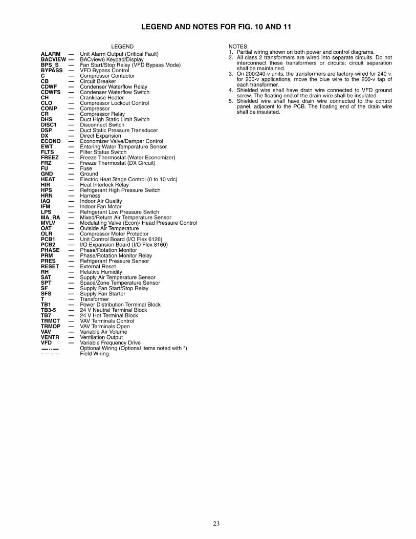
23
LEGEND AND NOTES FOR FIG. 10 AND 11
LEGEND NOTES:1. Partial wiring shown on both power and control diagrams.2. All class 2 transformers are wired into separate circuits. Do not
interconnect these transformers or circuits; circuit separationshall be maintained.
3. On 200/240-v units, the transformers are factory-wired for 240 v.for 200-v applications, move the blue wire to the 200-v tap ofeach transformer.
4. Shielded wire shall have drain wire connected to VFD groundscrew. The floating end of the drain wire shall be insulated.
5. Shielded wire shall have drain wire connected to the controlpanel, adjacent to the PCB. The floating end of the drain wireshall be insulated.
ALARM — Unit Alarm Output (Critical Fault)BACVIEW — BACview6 Keypad/DisplayBPS_S — Fan Start/Stop Relay (VFD Bypass Mode)BYPASS — VFD Bypass ControlC — Compressor ContactorCB — Circuit BreakerCDWF — Condenser Waterflow RelayCDWFS — Condenser Waterflow SwitchCH — Crankcase HeaterCLO — Compressor Lockout ControlCOMP — CompressorCR — Compressor RelayDHS — Duct High Static Limit SwitchDISC1 — Disconnect SwitchDSP — Duct Static Pressure TransducerDX — Direct ExpansionECONO — Economizer Valve/Damper ControlEWT — Entering Water Temperature SensorFLTS — Filter Status SwitchFREEZ — Freeze Thermostat (Water Economizer)FRZ — Freeze Thermostat (DX Circuit)FU — FuseGND — GroundHEAT — Electric Heat Stage Control (0 to 10 vdc)HIR — Heat Interlock RelayHPS — Refrigerant High Pressure SwitchHRN — HarnessIAQ — Indoor Air QualityIFM — Indoor Fan MotorLPS — Refrigerant Low Pressure SwitchMA_RA — Mixed/Return Air Temperature SensorMVLV — Modulating Valve (Econ)/ Head Pressure ControlOAT — Outside Air TemperatureOLR — Compressor Motor ProtectorPCB1 — Unit Control Board (I/O Flex 6126)PCB2 — I/O Expansion Board (I/O Flex 8160)PHASE — Phase/Rotation MonitorPRM — Phase/Rotation Monitor RelayPRES — Refrigerant Pressure SensorRESET — External ResetRH — Relative HumiditySAT — Supply Air Temperature SensorSPT — Space/Zone Temperature SensorSF — Supply Fan Start/Stop RelaySFS — Supply Fan StarterT — TransformerTB1 — Power Distribution Terminal BlockTB3-5 — 24 V Neutral Terminal BlockTB7 — 24 V Hot Terminal BlockTRMCT — VAV Terminals ControlTRMOP — VAV Terminals OpenVAV — Variable Air VolumeVENTR — Ventilation OutputVFD — Variable Frequency Drive
Optional Wiring (Optional items noted with *)Field Wiring
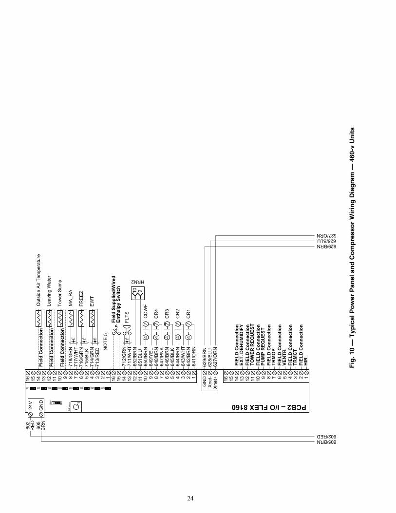
24
123456789101112131415161234567891011121314151612345678910111213141516
Xne
t+X
net-
GN
D
ON 1OFF
Add
ress
W1 W2 W4 W5 W6 W7 W8 W9
PCB2 – I/O FLEX 8160
24V
GN
D
717/
WH
T71
8/G
RN
MA
_RA
649/
YE
L65
0/B
RN
CD
WF
715/
BLK
716/
GR
NFR
EE
Z
EWT
713/
RE
D71
4/G
RN
FIEL
D C
onne
ctio
nPU
MP
REQ
UES
T
FIEL
D C
onne
ctio
nTO
WER
REQ
UES
T
FIEL
D C
onne
ctio
nEX
T. D
EHU
MID
IFY
Tow
er S
ump
Leav
ing
Wat
er
627/
OR
N62
8/BL
U62
9/BR
N
FIEL
D C
onne
ctio
nTR
MO
PFI
ELD
Con
nect
ion
VEN
TRFI
ELD
Con
nect
ion
TRM
CT
FIEL
D C
onne
ctio
nH
IR
Out
side
Air
Tem
pera
ture
HRN2
711/
WH
TFL
TS71
2/G
RNN
OTE
5
652/
BR
N65
1BLU
Fiel
d C
onne
ctio
n
Fiel
d C
onne
ctio
n
Fiel
d C
onne
ctio
n
642/
BR
N
647/
PN
K
641/
OR
N
648/
BR
N
910
CR
1
Fiel
d Su
pplie
d/W
ired
Enth
alpy
Sw
itch
47
47
CR
4
47
646/
BR
N64
5/B
LKC
R3
47
644/
BR
N64
3/W
HT
CR
24
7
627/ORN628/BLU629/BRN
605/BRN602/RED
602
RE
D60
5B
RN
Fig
. 10
— T
ypic
al P
ow
er P
anel
an
d C
om
pre
sso
r W
irin
g D
iag
ram
— 4
60-v
Un
its
a50-8752
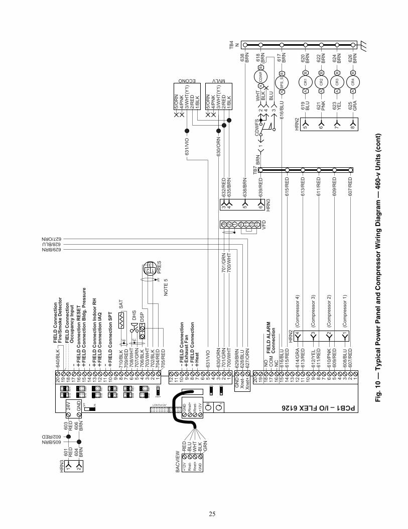
25
3 2 1 1110 1312 VFD
1234567891011121234567891011121314151617181920 1234567891011121314151617181920
Xne
t+Xn
et-
GN
D
10V10V+5V
+24V
IN01
IN02
IN03
IN04
IN05
IN06
IN07
IN08
IN09
IN10
IN11
IN12
24V
GN
DO
FF
ON 0 1
+12V
Rne
t-R
net+
GN
DLON Port 2b* PCB1–I/OFLEX6126
-+
TB7
HR
N2
TB4
N
700/
WH
T70
1/G
RN
610/
PN
K
612/
YEL
614/
GR
A
708/
WH
T70
7/G
RN
DH
S
706/
BLK
NO
TE5
616/
BLU
608/
BLU
635/
BRN
632/
RED
631/
VIO
630/
OR
N
MVLVECONO
234 1
700/
WH
T70
1/G
RN
630/
OR
N
631/
VIO
HR
N3
43
- +FIEL
DC
onne
ctio
nEx
haus
tFan
DS
P
640/
BLK
AB
BPS_
S61
7BR
N
- + ++
6563
8/BR
N63
8B
RN
627/
OR
N62
8/BL
U62
9/BR
N
603
RE
D60
6B
RN
639/
RED
607/
RE
D
609/
RE
D
611/
RE
D
613/
RE
DFIEL
DA
LAR
MC
onne
ctio
nN
C
NO
CO
M
615/
RE
D
FIEL
DC
onne
ctio
nFi
re/S
mok
eD
etec
tor
+ - +FIEL
DC
onne
ctio
nH
eat
+
13
2
PR
ES
703/
WH
T70
2/BL
K70
4/R
ED
705/
RE
D
- FIEL
DC
onne
ctio
nSP
T
FIEL
DC
onne
ctio
nIA
QFI
ELD
Con
nect
ion
Indo
orR
H
FIEL
DC
onne
ctio
nR
ESET
FIEL
DC
onne
ctio
nB
ldg.
Pres
sure
(Com
pres
sor1
)
(Com
pres
sor2
)
(Com
pres
sor3
)
(Com
pres
sor4
)
CD
WF S
618
BRN
BLU
BLK
WH
TBR
N2 4 3
1
607/
RED
609/
RED
611/
RED
613/
RED
615/
RED
616/
BLU
619
BLU
HR
N2
AB
CR
15
620
BR
N
621
PN
KA
BC
R2
662
2B
RN
623
YEL
AB
CR
37
624
BR
N
625
GR
AA
BC
R4
862
6B
RN
709/
RED
710/
BLK
SAT
-
AB
CD
WF
FIEL
DC
onne
ctio
nO
ccup
ancy
Inpu
t
HR
N3
601
RE
D60
4B
RN
21
627/ORN628/BLU629/BRN
605/BRN602/RED
GN
DR
net+
Rne
t-+1
2V
BAC
VIEW
RE
DB
LUW
HT
BLK
GR
N
1/B
LK2/
RE
D3/
WH
T(Y
1)4/
PN
K5/
OR
N
1/B
LK2/
RE
D3/
WH
T(Y
1)4/
PN
K5/
OR
N
Fig
. 10
— T
ypic
al P
ow
er P
anel
an
d C
om
pre
sso
r W
irin
g D
iag
ram
— 4
60-v
Un
its
(co
nt)
a50-8753
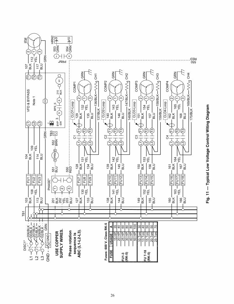
26
L2 L3L1T1 T3T2
VFD
& B
YPA
SS
Not
e 1
GN
DJ1
01
BYP -SW
39
6
BP
S_S
215
BLK
M1
01
CLO
3-Lo
op
CLO
2-Lo
op
321
IFM
107
BLK 117
BLU
112
YEL
DIS
C1*
USE
CO
PPER
SU
PPLY
WIR
ES.
104
BLK 114
BLU
109
YEL
2 1 3
FU1
FU2
FU3
Phas
e ro
tatio
n se
quen
ce is
A
BC
(L1-
L2-L
3).
GR
NG
RN
CO
MP
1
CO
MP
2
129
BLK 135
BLU
132
YEL
128
BLK 134
BLU
131
YEL
127
BLK 133
BLU
130
YEL
140
BLK 146
BLU
143
YEL
139
BLK 145
BLU
142
YEL
138
BLK 144
BLU
141
YEL
C1
C2
136/
BLK
137/
BLK
CH
1
147/
BLK
148/
BLK
CH
2
2 1 3
FU7
FU8
FU9
2 1 3
L1T1
L2T2
L3T3
L1T1
L2T2
L3T3
FU10
FU11
FU12
CO
MP
315
1B
LK 157
BLU
154
YEL
150
BLK 156
BLU
153
YEL
149
BLK 155
BLU
152
YEL
C3
158/
BLK
159/
BLK
CH
3
2 1 3
L2T2
L3T3
FU13
FU14
FU15
CO
MP
416
2B
LK 168
BLU
165
YEL
161
BLK 167
BLU
164
YEL
160
BLK 166
BLU
163
YEL
C4
169/
BLK
170/
BLK
CH
4
L2T2
L3T3
FU16
FU17
FU18
GR
N
GR
N
GR
N
GR
N
PH
AS
E*
203
BLU20
1BL
K20
2YE
L
GN
D
L2 L3L1 GN
D
TB1
100/
BLK
101/
BLK
102/
BLK G
RN
206/
BLK
207/
BLK
208/
BLK
Fus
es: 6
00 V
, Cla
ss R
K-5
FUSE
U
SAG
E A
15 H
P 35
20
HP
40
25 H
P 60
30
HP
80
40 H
P 80
FU1-
3 (R
K-5
)
50 H
P 10
0 10
Ton
30
13
Ton
40
15
Ton
50
20
Ton
50
FU 7
-18
(RK
-5)
25 T
on
70
HR
N2
L1T1
L1T1
AB
PR
M
47
PRM*
TB3
CLO
1-Lo
op
CLO
4-Lo
op
103
BLK
108
YEL
113
BLU
2 1 3
9 10
551
BLU 550
RE
D
552
BRN
554
OR
N
553
OR
N
550RED
Fig
. 11
— T
ypic
al L
ow
Vo
ltag
e C
on
tro
l Wit
ing
Dia
gra
m
a50-8754
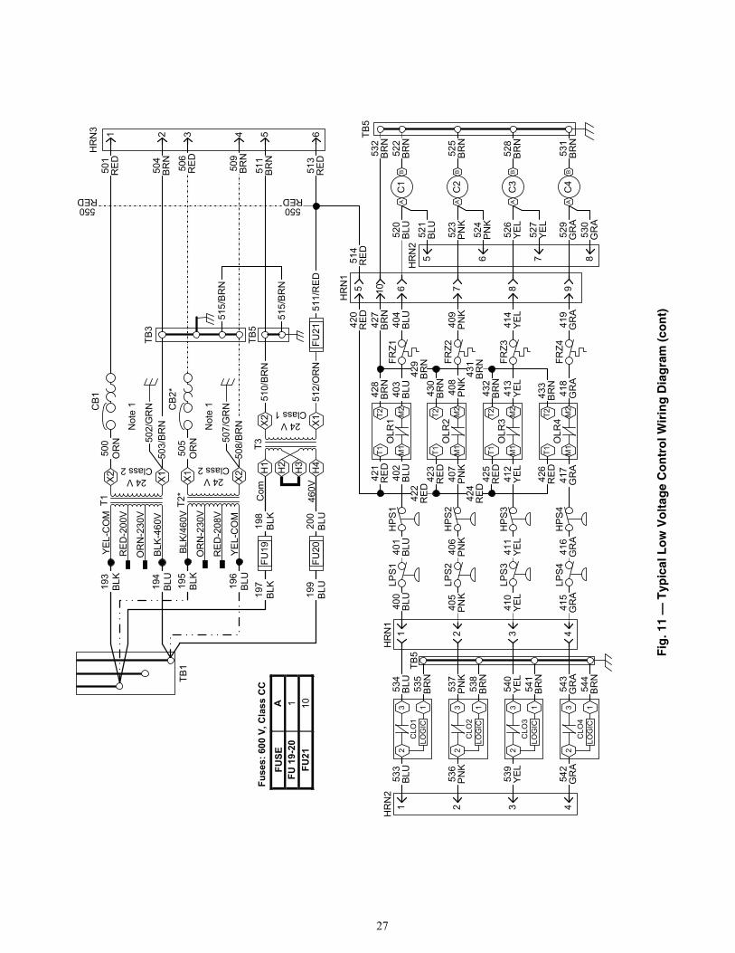
27
OLR
4M
2M
1
T1T2
OLR
3M
2M
1
T1T2
OLR
1M
2M
1
T1T2
OLR
2M
2M
1
T1T2
3
LOG
IC1
2C
LO4
3
LOG
IC1
2C
LO3
3
LOG
IC1
2C
LO2
3
LOG
IC1
2C
LO1
198
BLK 200
BLU
197
BLK 199
BLU
T2* 460V
Com
195
BLK 196
BLU
FU19
FU20
24 VClass 2
YEL-
CO
M
RE
D-2
08V
OR
N-2
30V
BLK
/460
VX1 X2
T3
CB
2*
43
507/
GR
N50
8/B
RN
551
0/B
RN
6FU
2151
2/O
RN
TB3
511/
RE
D
550RED
505
OR
N
HR
N1
HR
N1
415
GR
A54
3G
RA
HP
S4
FRZ4
419
GR
A41
8G
RA
417
GR
A41
6G
RA
LPS
4
410
YEL
540
YEL
HP
S3
FRZ3
414
YEL
413
YEL
412
YEL
411
YEL
LPS
3
405
PN
K53
7P
NK
HP
S2
FRZ2
409
PN
K40
8PN
K40
7P
NK
406
PN
KLP
S2
400
BLU
534
BLU
HP
S1
FRZ1
404
BLU
403
BLU
402
BLU
401
BLU
LPS
1
TB5
531
BRN
528
BRN
525
BRN
522
BRN
532
BRN
427
BRN
433
BR
N
432
BRN
430
BRN
428
BRN
429
BR
N
431
BR
N
426
RED42
5R
ED423
RED42
1R
ED
420
RED
424
RE
D
AB
C1
511
BRN
506
RE
D
509
BR
N
513
RED
AB
C4
AB
C3
AB
C2
544
BRN
541
BRN
538
BRN
535
BRN
6 7 8 9105
520
BLU
514
RED
523
PN
K
526
YEL
529
GR
A
1 2
422
RE
D
3 4
TB5
HR
N2
1 2 3 4
533
BLU 53
6P
NK
539
YEL
542
GR
A
HR
N2
521
BLU 52
4P
NK
527
YEL
530
GR
A
5 876
Not
e 1
T119
3BL
K
194
BLU
24 VClass 2
BLK
-460
V
OR
N-2
30V
RE
D-2
00V
YE
L-C
OM
X2 X1
CB
1H
RN
3 1 250
2/G
RN
503/
BR
N
500
OR
N50
1R
ED 504
BRN
Not
e 1
Fuse
s: 6
00 V
, Cla
ss C
C
FUSE
AFU
19-
20
1FU
2110
TB5
515/
BR
N
515/
BR
N
TB1
550RED
H1
X2 X1
H2
H3
H4
24 VClass 1
Fig
. 11
— T
ypic
al L
ow
Vo
ltag
e C
on
tro
l Wir
ing
Dia
gra
m (
con
t)
a50-8755

Manufacturer reserves the right to discontinue, or change at any time, specifications or designs without notice and without incurring obligations.Catalog No. 04-53500096-01 Printed in U.S.A. Form 50XJ-1T Pg 28 10-12 Replaces: New
2012 Carrier Corporation